Embed Size (px)
Citation preview

Design and performance improvement of the LED Array
De Silva G H C N
EN13540036
1

Key points should be achieved.
1) Total number of LEDs,
500 LUX Level
15 ft. X 15 ft. area.
3m ( 9ft 10.11024in) above from the surface.
2) Equal circuit of modeled LED.
3) Thermal management strategy.
4) Demonstrate the Product.
2

Calculate the Lumen Value of a LED.
Reference:[1] Specification for White LED – NSPW 500DS, NICHIA Corparation.
[1]
[1]
3

Cont.…
[1]
Reference:[1] Specification for White LED – NSPW 500DS, NICHIA Corparation.
4

Cont.…
Surface Area = 15 ft. X 15 ft. = 20.9032 Square meter
-90° to +90° Wide angle
Single LED
3m(9ft 10.11024in)
5

Cont.…
• we use equation 6 to find relevant Lux Value,
IV = EV. D2
27 = EV * 32
EV = 27/9 = 3Lux
• Then we use equation 4 to find the Lumen value,
ɸv = Ev * A
ɸv = 3 * 20.9032 = 62.7026 Lumen
[1]
References:[1] 2016.[Online],Available:http://www.compuphase.com/electronics/candela_lumen.htm .[Accessed: 10, May, 2016]
6

Calculate the Total Number of LEDs Then we use below equation and its derivations to calculate total number of bulbs,
• I = Ll C
u L
LF / A
l
Where
• I = illumination (lux, lumen/m2
) (Consider the illumination of a 15ft * 15 ft
room in a house)
• Ll = luminance of lamp (lumen) ( Ll = luminance per bulb x Number of bulbs )
• Cu = coefficient of utilization
• LLF
= light loss factor
• Al = area per lamp (m
2
)
• = Ll = luminance per bulb x Number of bulbs
References:[1] 2016. [Online], Available: http://personal.cityu.edu.hk/~bsapplec/lumen.htm [Accessed: 20, April, 2016][2] 2016. [Online], Available: http://studentnotes.co.uk/2360/lumen_method.php [Accessed: 20 April, 2016]
[1] , [2]
7

Calculate the Total Number of LEDs continue…
• Cu = 0.64, LLF = 0.8, I = 500Lux, A = 20.9032, l per bulb = 62.7026Lumen
Vf
8

Model the LED.
• There are 03 main methods of LED modeling.
1)An equal resistance model
2)A linear Model
3)Linear electro thermal model
References:
[1] Bender V. C, Marchsan B.T, Solid-State Lighting, IEEE Electronics Magazine, 9th Volume, June, 2015.
[1]
[1]
[1]
9

Model the LED by Using Linear Model Method
≈
10

Modeled LED Array Each resistor should be0.56 Ω * 13 = 7.28 Ω
11

Power Calculations of the Array.
Each resistor should be0.56 Ω * 13 = 7.28 Ω
• each 7.28 ohm resistor dissipates 2.912 mW ( p= I*I *R)
• together, all resistors dissipate 72.8 mW ( = p *25)
• together, the diodes dissipate 19955 mW ( =325 * V* I)
• total power dissipated by the array is 20027.8 mW
• the array draws current of 500 mA from the source
12

Thermal Management (Seebeck Methode) [1/3]
What is seebeck method?
• The Seebeck effect is a phenomenon in which a temperature difference between two dissimilar electrical conductors or semiconductors produces a voltage difference between the two substances.
• When one of the two conductors or semiconductors is become heated, heated electrons flow toward the cooler one. If the pair is connected through an electrical circuit, direct current (DC) flows through that circuit.
• Seebeck Element can be used to convert heat into electric power.
References:
[1] Neva Agarwala, Thermoelectric Measurements of Silicon Nanowire Arrays for the Seebeck Effect, 2nd International Conference on Advances in Electrical Engineering (ICAEE 2013), Dhaka, Bangladesh, 19-21 December, 2013
13

Thermal Management Cont.… [2/3]
• http://www.mhtl.uwaterloo.ca/Professional_Animation_Seebeck_File_HTML.html
14
References:[1] 2016.[Online],Available :http://www.mpoweruk.com/thermoelectricity.htm.[Accessed: 21,september,2016]
[1]

Thermal Management Cont.… [3/3]
15

Design the Physical structure of the LED Product.
16
Front lookBack side look side look
Top look

Circuit Diagram
17

18
Seebeck Element Connection

Necessary items (1/3)
Item name Quantity
NSPW500DS LEDs 325
Dot board 01
Heat sink 02
5.1Ω resistors (1W) 13
2.2Ω resistors (1W) 13
Peltier 15
Indicator lamp (Red, Orange, Green) 03
Selector switch 01
ON/OFF switch 0119

Necessary items Cont. (2/3)
20
Cooling fan Large (12V) 02
Cooling fan small (12V) 01
Reflector sticker (ORACAL 352) 1ft x 4ft
230 AC/ 40V DC power supply 01
DC base 01
Aluminum bar 4ft x 0.5ft
Cladding boards (white) 1.75ft x 0.5ft
Black sticker 1m x 0.5m
Glass (5mm) 1.25ft x 0.5ft
3 core wire cord with 0.75A fuse protector 01
Glue sticks 03
Super glue 01
Heat Sleeves (Heat Shrinkage) 15

Necessary items Cont.(3/3)
21
Flexible wire (TT wire) 2 x 0.50 mm2 1.5m (Approximately)
Heat Transferable Gum (Heat sick Compounder) 01
SKC ROCK, Super solder wire 0.5mm, 60/40, 500g Roll 01
Steel Epoxy glue 01

Purchase and order the items.
22

Construct the Product.
1. Construct the LED Array
2. Make the thermal management system.
3. Make the LED casing.
4. Fit the all items to the casing.
23

Construct the LED Array (1/3)
Step 01
Collect the all necessary items. Ex: LEDs 325, Dot Board, Resistors ….etc.
Step 02
Check the each LED bulb one by one.
Step 03
Clean the edges of each LED by using a paper cutter. Because Oxide can be attached on the edge.
24
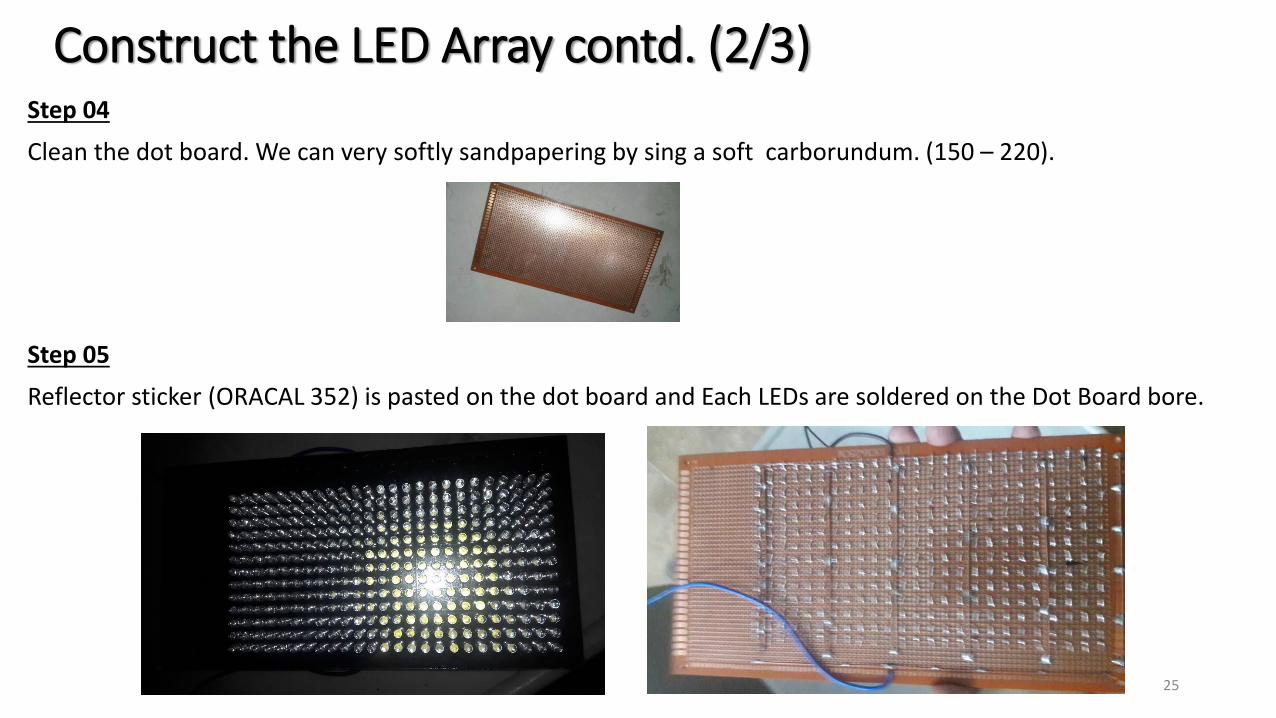
Construct the LED Array contd. (2/3)Step 04
Clean the dot board. We can very softly sandpapering by sing a soft carborundum. (150 – 220).
Step 05
Reflector sticker (ORACAL 352) is pasted on the dot board and Each LEDs are soldered on the Dot Board bore.
25
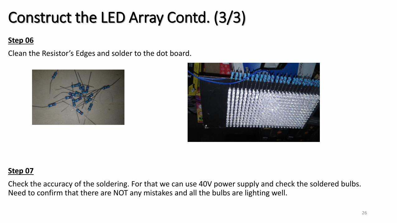
Step 06
Clean the Resistor’s Edges and solder to the dot board.
Step 07
Check the accuracy of the soldering. For that we can use 40V power supply and check the soldered bulbs. Need to confirm that there are NOT any mistakes and all the bulbs are lighting well.
26
Construct the LED Array Contd. (3/3)

Make the thermal management system. (1/2)
Step 01
Clean the surfaces of the two heat sinks (For removing the Oxide film) by using a sandpaper (100) and Affix the two heat sinks by using Steel Epoxy glue.
Step 02
Find the hot surfaces of the 15 peltiers. For that, we can use 12V DC power supply and connect + and –edges with peltier’s one. By touching the two surfaces, we can sense the hot surface of the peltiers. Do this checking to all 15 pelties and find the hot surface

Make the thermal management system Contd. (2/2)
Step 03
Paste the 15 peltiers on the two heat sinks surfaces by using heat transferable glue. Connect the peltiers as series and connect wires edges by using heat shrinkage joints.

Make the LED casing.Step 01
Make the LED product’s casing by using Aluminum, cladding board and 5mm glass.
Step 02
Paste the Reflector sticker in to the inside the Casing.
Step 03
Drill the holes to fit the indicator lights to the casing.

Fit the all items to the casing. (1/3)Step 01
Cooling fans and DC base are connected on the backside cladding board of the LED casing.
Step 02
Connect the wires to the ON/OFF switch & Indicator lights and connect them to front side cladding board of the casing.

Fit the all items to the casing Contd. (2/3)Step 03
Fixation the LED array to the casing.
Step 04
Set the peltires and the heat sink (Thermal management system) to the LED array in the casing.

Fit the all items to the casing Contd. (3/3)Step 05
Paste the 230V AC / 40V DC power supply to the LED casing by using glue stick and connect the wires.
Step 06
Connect the all wires inside the casing and check the accuracy of the system. Finally plug socket to the 230V AC plug Point and switch ON. Test the system.

Project costItem Quantity Unit price (Rs) Price (Rs)
TEC1-12706 Peltier 15 425 6375
5mm white LED cool White 4.5 325 1462.5
Heat sink mediam 2 600 1200
12V cooling fan small 1 100 100
dot board large 1 175 175
indicator bulb 3 30 90
ON/OFF switch 1 35 35
selector switch 1 80 80
nob 1 10 10
12V cooling fan large 2 140 280
LED product full casing 1 1350 1350
40V power AC/DC power supply 1 1200 1200
heat transferable glue 1 600 600
steel epoxy 1 190 190
Heat sleeves 15 10 150
Flexible wire 1 125 125
3 core cable with fuse 1 450 450
glue stick 3 30 90
super glue 1 40 40
ORACAL 352 1 435 435
Resistors (1W) 50 13 650
DC base 1 25 25
Black sticker 1 450 450
Super solder wire 0.5mm 1 200 200
TOTAL (Rs) 15762.5

Future work
Product development
i. Weight reduction.
ii. Improve the wiring order
iii. Design a voltage step up module for thermal management system
iv. Improve the viewing angle of the bulb.
v. Setting an attractive price
vi. Achieving the industrial standard. (Bench- mark)
vii. Improving the attractively of the product.
viii. Introducing the new varieties for the product.

Future work
• Found Our Own LED production Company.we planned a conceptual company for LED production. This conceptual company invents and makes all kind of LED products to the global and local market with the competitive price and quality.
Vision of Our companyThe global leading partner for sustainable and environmental friendly lighting solutions.
Mission of Our companyDesigns and supplies sustainable lighting solutions for all customers, enabling them to reduce costs, energy consumption and environmental impact.
Aim of Our companyColor the whole world.

LOGO of Our Company.
Future work

Future work

Thank you !