Embed Size (px)
Citation preview

33
Size and shapeFacilities exist to galvanize components of virtually any sizeand shape. When an article is too big for single immersion inthe largest bath available it may be possible to galvanize it bydouble-end dipping, depending on the handling facilities andlayout of the galvanizing plant. Large cylindrical objects canoften be galvanized by progressive dipping.
The chart below shows the dimensions of work that couldtheoretically be galvanized by double-end dipping in (forexample) a bath 8m long x 2m deep, assuming that the width of the work also suits the bath.
Schematic indication of double-end dipping capacity of a galvanizing bath 8 metres long x 2 metres deep
The chart shows that a bath nominally 8m long x 2m deepcould process work 7.75m x 3.5m, or long components of up to about 14m. Note that the chart is purely indicative and similar charts can be prepared for baths of differentdimensions. The maximum sizes which a particular galvanizercan process should always be checked at the design stage.
Bath lengths of 12.5 metres are available.
Modular designLarge structures are also galvanized by designing in modulesfor later assembly by bolting or welding. Modular designtechniques often produce economies in manufacture andassembly through simplified handling and transport.
Weld areas in structures assembled by welding aftergalvanizing must be repaired to give corrosion protectionequivalent to the galvanized coating as described on page 45.
The size and shape of large or unusual structures shouldalways be checked with the galvanizer early in the designprocess.
Materials suitable for galvanizingAll ferrous materials can be galvanized. Mild and low alloysteels and iron and steel castings are all regularly andsuccessfully galvanized. Steel fabrications which incorporatestainless steel parts and fittings are also readily galvanized.
Soft-soldered assemblies cannot be galvanized. Brazedassemblies may be galvanized, but the galvanizer should beconsulted at the design stage.
Castings. The galvanizing of sound stress-free castings withgood surface finish will produce high quality galvanizedcoatings. The following rules should be applied in the designand preparation of castings for galvanizing:
1 Design for uniform section thicknesses wherever possible. 2 Use large radii at junctions with webs, fillets and raised
features such as cast-in part and pattern numbers. 3 Avoid deep recesses and sharp corners.4 Large grey iron castings should be normalised by the
fabricator.5 Castings should be abrasive blast cleaned by the
fabricator to remove foundry sand and surface carbon.Alternatively castings may be cleaned electrolytically usingthe Kolene process.
Design, specification, inspectionofgalvanizedproducts
Consistently good galvanized steel products will be produced when the essential requirements listed areincorporated at the design and fabrication stages of production. Design features should be discussed with thegalvanizer. Close liaison between design engineer, materials engineer, specifier, fabricator and galvanizer willensure high quality galvanized products, minimum cost and faster delivery.
1 2 3 4 5 6 7 8 9 10 11 12 13 14 15
0.5
1.0
1.5
2.0
2.5
3.0
3.5
4.0
Maximum size of workfor single dip - 1.75 X 7.75 m
Maximumsize ofworkwhichcan becoatedby double-enddippingfor excessdepth:3.5m x7.75m
Maximum size of work which can be coated by double end dipping for excess length – up to 14.3 m
7.75m14.3m
3.5m
Double-end dipping for excess depth Double-end dipping for excess length Progressive dipping

34
35
Combinations of ferrous materials and surfaces. Theremay be appreciable variation in the pickling times of variousferrous metals and differing surface conditions. Fabricatedassemblies containing a mixture of materials and surfacessuch as a combination of castings with other steels, or newor machined steel surfaces with rusted or scaled steelsurfaces, must be abrasive blast cleaned to minimisedifferences in pickling time.
Omission of abrasive blast cleaning will result in combinedunder- and over-pickling of the different surfaces, producingpoor quality galvanized coatings of unsatisfactoryappearance.
Heavy mill scale on rolled steel surfaces should be removedby abrasive blast cleaning before galvanizing.
Thicker than normal galvanized coatings are produced whenabrasive blast cleaned surfaces are galvanized as discussedon page 13.
Steel pipe for fabrication of galvanized assemblies should bespecified by the fabricator when ordering from the merchantas ‘Not oiled or painted’. Manufacturers produce steel pipewith clear varnish or black bituminous coatings which are bydesign extremely resistant to chemical removal andnecessitate expensive manual stripping before pickling toensure satisfactory galvanizing.
Heavy gauge seamless pipe must also be clearly specified inthe unoiled, unpainted condition when ordering.
Weld areas. Due to the silicon content of some weldingrods, weld areas may produce localised grey coatings whengalvanized. The galvanized coating is likely to be slightlythicker in these areas and will have no detrimental effect oncoating life.
As discussed on pages 13 and 42, the development of greycoatings due to silicon steels is entirely related to steelcomposition and cannot be controlled by the galvanizer. Evenwhen these weld areas are ground flush prior to galvanizing,heavier grey coatings may still result.
Welding slags. Arc welding slags are chemically inert in acidcleaning solutions and must be mechanically removed beforearticles are delivered to the galvanizer The fabricator shouldremove these by chipping, wire brushing, flame cleaning,grinding or abrasive blast cleaning.
Welding electrode manufacturers supply general purposeelectrodes coated with fluxes which produce virtually self-detaching slags and their use is recommended.
Good joint design with adequate access facilitates thewelding process to produce sound continuous welds,avoiding locked-in slag, and easing slag removal.
Design and fabrication ofcomponents for galvanizingSafety
Vessels or hollow structures which incorporate enclosedsections must have provision for adequate venting duringgalvanizing. At galvanizing temperatures any moisture presentin closed sections is rapidly converted to superheated steam,generating explosive forces unless adequately vented to theatmosphere. For the safety of galvanizing personnel,equipment, and the work being galvanized it is essential thatventing is provided.
Correct venting also ensures that the entire internal surface ofwork is properly galvanized and fully protected.
Closed vessels which are not to be galvanized inside, suchas certain types of heat exchanger, must be provided with
snorkel-type vent pipes long enough to project above thelevel of pickling, fluxing and galvanizing baths when the workis fully immersed. The exact venting requirement should bediscussed with the galvanizer.
Venting, filling and drainingThe following specific recommendations should be followed:
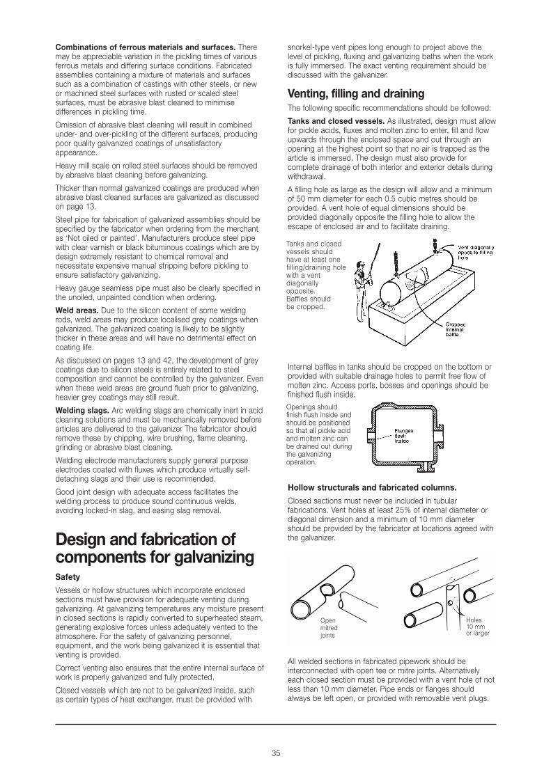
Tanks and closed vessels. As illustrated, design must allowfor pickle acids, fluxes and molten zinc to enter, fill and flowupwards through the enclosed space and out through anopening at the highest point so that no air is trapped as thearticle is immersed. The design must also provide forcomplete drainage of both interior and exterior details duringwithdrawal.
A filling hole as large as the design will allow and a minimumof 50 mm diameter for each 0.5 cubic metres should beprovided. A vent hole of equal dimensions should beprovided diagonally opposite the filling hole to allow theescape of enclosed air and to facilitate draining.
Internal baffles in tanks should be cropped on the bottom orprovided with suitable drainage holes to permit free flow ofmolten zinc. Access ports, bosses and openings should befinished flush inside.
Hollow structurals and fabricated columns.
Closed sections must never be included in tubularfabrications. Vent holes at least 25% of internal diameter ordiagonal dimension and a minimum of 10 mm diametershould be provided by the fabricator at locations agreed withthe galvanizer.
All welded sections in fabricated pipework should beinterconnected with open tee or mitre joints. Alternativelyeach closed section must be provided with a vent hole of notless than 10 mm diameter. Pipe ends or flanges shouldalways be left open, or provided with removable vent plugs.
Openmitredjoints
Holes10 mm or larger
Openings shouldfinish flush inside andshould be positionedso that all pickle acidand molten zinc canbe drained out duringthe galvanizingoperation.
Tanks and closedvessels shouldhave at least onefilling/draining holewith a ventdiagonallyopposite.Baffles shouldbe cropped.
36

37
Closing of unwanted vent holes. Small vent holes whichare necessary for galvanizing but not wanted in the finishedjob may be closed by hammering in lead plugs aftergalvanizing and filing off flush with surrounding surfaces, or by the use of threaded plugs. Threads may need re-tapping after galvanizing.
Welded strengthening gussets on fabricated columns andstrengthening gussets in members fabricated from channelsections should have corners cropped to allow free flow ofzinc during galvanizing as illustrated.
Overlapping surfaces. Narrow gaps between plates andin particular, overlapping surfaces and back-to-backangles and channels should be avoided. As discussed onpage 35 under ‘Safety’, any pickle acid or rinse watertrapped in narrow gaps between members is rapidlyconverted to superheated steam at galvanizingtemperatures, with the possibility of an explosion.
Where small overlapping areas are unavoidable, edgesshould be sealed after consultation with the galvanizer, by acontinuous pore-free weld to prevent penetration of pickleacid. For the safety of galvanizing personnel the sealed areamust be provided with a vent hole for every 100 cm2 ofsealed area according to the following table:
Steel plate thickness Vent hole size
Up to 6 mm At least 6 mm diameterOver 6 mm Hole diameter to match or
exceed plate thickness
Back-to-back channels should be avoided. C below ispotentially dangerous because of the risk of explosion.
Dimensional stabilityIn certain cases, fabricated assemblies may be liable to lossof shape at galvanizing temperatures due to the release ofstresses induced during manufacture of the steel and insubsequent fabricating operations. These stresses may becompounded by bad design incorporating unequalthicknesses or non-symmetrical sections. Observance of thefollowing recommendations will improve dimensional stability:1 Avoid designs which require double-end dipping to fit into
the galvanizing bath. It is preferable to build assembliesand sub-assemblies in suitable modules so that they canbe immersed quickly and fully in a single dip.
2 Use symmetrical sections in preference to angles orchannels.
3 Use sections of near equal thickness at joints. 4 Bend members to the largest acceptable radii. 5 Accurately preform parts to avoid force or restraint during
joining.6 Continuously weld joints if possible using balanced
welding techniques to reduce uneven thermal stresses.Balanced, staggered welding is permissible. For staggeredwelding of material of 3 mm and lighter, weld centresshould be closer than 100 mm.
7 Design castings to conform to the rules listed on page 33.Large grey iron castings should always be normalised bythe fabricator and then abrasive blast cleaned prior togalvanizing.
ASTM A384-59 ‘Recommended practice for safeguardingagainst warpage and distortion during galvanizing of steelassemblies’ gives further information. Advice on design tominimise distortion is available from the galvanizer.
Use of symmetrical sections minimises distortion during galvanizing.Avoid combinations of thick and thin materials.
Clearance for moving partsMoving parts such as drop handles, hinges, shackles andshafts must incorporate minimum radial clearances asdetailed below:
Shaft or spindle size Minimum radial clearance
Up to 10 mm diameter 1.0 mm10 to 30 mm diameter 2.0 mmOver 30 mm diameter 2.5 mm
Galvanized threads
When assemblies to be galvanized incorporate threadedcomponents, the tolerance normally allowed on internalthreads must be increased to provide for the thickness of thegalvanized coating on external threads. Standard practice isto tap nuts oversize after galvanizing, according to figures inthe table on page 48.
For economy, nuts are sometimes galvanized as blanks andthreads are tapped after galvanizing. Uncoated internalthreads are acceptable since the zinc coating on the externalthread provides full corrosion protection.Bolted assemblies should be presented for galvanizing in the disassembled condition. Nuts and bolts or studs forgalvanizing should also be supplied disassembled. When internal pre-tapped threads included in componentsare required not to be galvanized they may be pluggedtemporarily by means of bolts or studs screwed fully in, after discussion with the galvanizer.For safety reasons, high strength bolts must not be welded to galvanized structures for use as high strengthstuds. Galvanized bolts and the bolting of galvanizedstructures are discussed in detail commencing on page 47.
To prevent the possiblityof an explosion duringgalvanizing, a vent holemust be provided forevery 100 cm2 of sealedarea, as specified in thetable above.
Nuts for galvanized studsmust be tapped oversize.The galvanized coating onthe stud providescorrosion protection forthe internal tread.

38

39
Handling parts for galvanizingParts may require suspension holes if there is no convenientpoint to attach a jig or hook. No special requirements apply if the work can be handled by chains, baskets, tongs orracks. Your galvanizer will advise of necessary provision tosuit the handling equipment available.
Large pipe sections, open top tanks and similar structuresmay require cross stays to maintain the shape of the articleduring handling and galvanizing.
Marking for identificationFor temporary identification, water soluble paints or markingsare recommended. Oil-based paints should not be used asthey must be removed manually before galvanizing.
For permanent identification, intended to remain legible aftergalvanizing, the fabricator should provide heavily punched orembossed figures either on the work or on steel (not aluminium) tags wired to the work.
Design for maximum corrosionprotectionGalvanized coatings provide outstanding corrosion protectionfor steel. Treatment of design details in accordance with goodcorrosion design practice as discussed below will furtherincrease the life of galvanized steel fabrications.
Many of the design requirements for good galvanizingdetailed earlier, such as the provision of flush-finished internalflanges in tanks and vessels will also ensure good drainage inservice and optimum corrosion resistance.
Fabricated assemblies should be designed to eliminateundrained areas which will collect water and sediment inservice, producing localised corrosion pockets. The followingrules should be followed:
1 Use butt welds in preference to lap welds. 2 Where lap welds are used face joints downwards to avoid
collection of moisture and sediment. 3 Avoid use of horizontal boxed sections, ledges, seams
and flat undrained areas.4 Use rounded internal corners rather than squared corners
in vessels and containers to avoid build up of sediment. 5 Design to eliminate crevices and unnecessary openings. 6 Avoid contact of galvanized surfaces with brass or copper
as discussed under ‘Galvanic corrosion’, page 22.7 Provide ventilation where possible in condensation areas. 8 Under conditions of extreme humidity use an inhibitive
jointing compound such as Dulux Foster C1 Mastic orequivalent between contacting galvanized surfaces suchas roof overlaps.
9 Provide maintenance access where anticipated service lifeof certain components is less than that of the completestructure.
Galvanizing design aidsAs an aid to designers and specifiers, GalvanizersAssociation of Australia publishes and distributes free ofcharge the colour wall chart ‘Design for Galvanizing’.
GAA also provides the video ‘Hot dip galvanizing, Part 1:Insuring steel’s future’, and ‘Part 2: Design and fabrication for galvanizing’.
Contact GAA, Level 5, 124 Exhibition Street, Melbourne, Victoria 3000.
Metallurgical aspects of designThe galvanizing process has no effect on the mechanicalproperties of the structural steels commonly galvanized. Insusceptible steels the galvanizing process may accelerate theonset of strain ageing which, with ageing, would occurnaturally due to earlier cold working operations.
Strain ageing can be avoided by the use of non-susceptiblesteels, or when susceptible steels must be used, by adoptingthe procedures specified in relevant standards, as dicussedin more detail on pages 15 and 17.
Minimum edge distances for holes in structuralmembers
In bolted connections minimum edge distances from thecentre of any bolt to the edge of a plate or the flange of arolled section should be used as specified in the table below,taken from the Australian Standard 4100 ‘Steel structures’.
Sheared or hand Rolled plate, Rolled edge of aflame-cut edge, machine flame-cut, rolled flat bar
sawn or planed edge or section,flat bar or section,
1.75df 1.50df 1.25dfNote. Edge distance may also be affected by clause 9.3.2.4, AS 4100
Inspection of work beforedespatch to the galvanizerFabricated assemblies, castings and other components forgalvanizing should be inspected before despatch to thegalvanizer to ensure that the following points conform todesign requirements detailed earlier. This may avoid costlyrectification and delays at the galvanizing plant.Size and shape. Check that work is suitably sized anddimensioned for the handling and galvanizing facilities of theselected galvanizer. It may be too late to make changes tothe design, but it is costly to despatch work which thegalvanizer cannot process.Structural steel. Check that bending, punching andshearing have been carried out in conformity with therecommendations on page 17.
Satisfactory galvanizing
Observance of the points listed below and described in moredetail on previous pages will ensure optimum galvanizedproduct quality and minimise extra costs or delays:
1 Check that closed vessels and hollow structures arevented for safety and satisfactory galvanizing.
2 Check that welding slags have been removed.3 Check that assemblies comprising castings and steels of
widely differing surface conditions have been abrasiveblast cleaned to minimise differences in galvanized finish.
4 Check that castings are abrasive blast cleaned beforedespatch unless otherwise arranged. Check that largegrey iron castings have been normalised.
5 Check that appropriate temporary or permanent markingsare provided.

40
This specification has been prepared by the galvanizing industry through its technical working group, in consultation with industry and a number of consulting engineering groups. It is intended to be used in conjunction with Australian/New Zealand Standard 4680 and is designed for simple insertion into specifiers’ overall materials specifications.
NOTE
1 Prior to commencement of design it is recommended that the designer/fabricator refer to Australian/New Zealand Standard4680 Appendix C ‘Recommended procedures for design and preparation of materials prior to galvanizing’, and to the chapteron Design in the manual ‘Hot Dip Galvanizing’, produced by Galvanizers Association of Australia.
2 The designer is referred to the recommendations contained in Appendix D of AS/NZS 4680 to minimise distortion and reducethe likelihood of embrittlement occurring.
3 High strength low alloy steels, particularly those containing silicon can, when galvanized, produce brittle coatings which arethicker and different in colour to normal coatings. The high silicon content in weld deposits made by automatic weldingprocesses may result in thicker coatings being formed on these areas. These coating characteristics are usually beyond thecontrol of the galvanizer.
4 If the galvanized coating is to be subsequently painted or if an architectural finish or any other special treatment is required,these requirements should be brought to the attention of the galvanizer at the time of enquiry and order.
SCOPE
This specification covers the galvanized coating applied to general steel articles, structural sections, angles, channels, beams,columns, fabricated steel assemblies, threaded fasteners and other steel components.
This specification does not apply to the galvanized coating on semi-finished products such as wire, tube or sheet galvanized inspecialised or automatic plants.
RELEVANT STANDARDS
AS 1214-1983 Hot dip galvanized coatings on threaded fasteners.
AS 1627-1989 Part 1 Cleaning using liquid solvents and alkaline solutions.
AS 1627-1989 Part 4 Abrasive blast cleaning.
AS 1627-1975 Part 5 Pickling steel surfaces (in part).
AS/NZS 4680-1999 Hot-dip galvanized (zinc) coatings on fabricated ferrous articles.
GENERAL
The galvanized coating on all steel articles on the following drawings and material lists shall conform to the requirements ofAS/NZS 4680-1999 and as specified herein.
Drawings: _______________________________________________________________________________________________________________________
Items: ___________________________________________________________________________________________________________________________
FABRICATION
Care shall be taken to avoid fabrication techniques which could cause distortion or embrittlement of the steel.
All welding slag and burrs shall be removed prior to delivery to the galvanizer
Holes and/or lifting lugs to facilitate handling, venting and draining during the galvanizing process shall be provided at positions asagreed between the designer and the galvanizer.
Unsuitable marking paints shall be avoided and consultation by the fabricator with the galvanizer about removal of grease, oil,paint and other deleterious materials shall be undertaken prior to fabrication.
SURFACE PREPARATION
Surface contaminants and coatings, which cannot be removed by the normal chemical-cleaning process in the galvanizingoperation shall be removed by abrasive blast cleaning or some other suitable method.
Steelwork shall be precleaned in accordance with the requirements of AS 1627 Part 1 followed by acid pickling, in accordancewith the requirements of AS 1627 Part 5. Abrasive blast cleaning to Class 2 finish in accordance with the requirements of AS1627 Part 4 may be used.
GALVANIZING
All articles to be galvanized shall be handled in such a manner as to avoid any mechanical damage and to minimise distortion.(See Note 2 above)
Design features that may lead to difficulties during galvanizing should be pointed out prior to galvanizing.
Galvanizing parameters such as galvanizing temperature, time of immersion, and withdrawal speed shall be employed to suit therequirements of the article.
The composition of the zinc in the galvanizing bath shall not be less than 98.0% zinc.
Standard specification for hot dip galvanized coatings

41
COATING REQUIREMENTS
1 ThicknessThe thickness of the galvanized coating shall conform with Table 1 in AS/NZS 4680:Table 1. Requirements for coating thickness and mass for articles that are not centrifuged
Steel Thickness mm Local coating thickness minimum µm Average coating thickness minimum µm Average coating mass minimum g/m2
F1.5 35 45 320
>1.5 F3 45 55 390
>3 F6 55 70 500
>6 70 85 600
Note: 1 g/m2 coating mass = 0.14 µm coating thickness.The thickness of the galvanized coatings on threaded fasteners shall conform with Table 2 in AS 1214:Table 2. Requirements for coating thickness and mass for articles that are centrifuged
Thickness of articles (all components Local coating thickness Average coating thickness Average coating mass including castings) mm minimum µm minimum µm minimum g/m2
<8 25 35 250
G8 40 55 390
Notes: 1. For requirements for threaded fasteners refer to AS 1214. 2. 1 g/m2 coating mass = 0.14 µm coating thickness.The thickness of the galvanized coating shall first be tested by the purchaser/designer at the galvanizer’s works, using anapproved magnetic measuring device. In the event of any dispute, an independent test shall be carried out in accordance withAS/NZS 4680, Appendix G.2 Surface Finish
The galvanized coating shall be continuous, adherent, as smooth and evenly distributed as possible, and free from any defectthat is detrimental to the stated end use of the coated article. On silicon killed steels, the coating may be dull grey, providedthe coating is sound and continuous. (See Note 3)The integrity of the coating shall be determined by visual inspection and coating thickness measurements.Where slip factors are required to enable high strength friction grip bolting, where shown, these shall be obtained aftergalvanizing by suitable mechanical treatment of the faying surfaces.Where a paint finish is to be applied to the galvanized coating, all spikes shall be removed and all edges shall be free fromlumps and runs. (See Note 4 at left).
3 AdhesionThe galvanized coating shall be sufficiently adherent to withstand normal handling during transport and erection.
INSPECTIONInspection shall be carried out at the galvanizer’s works by a designated party, or at some other place as agreed betweenfabricator and galvanizer.
CERTIFICATEWhen requested by the purchaser/designer, a certificate shall be provided stating that the galvanizing complies with therequirements of AS/NZS 4680.
TRANSPORT AND STORAGEGalvanized components shall, wherever possible, be transported and stored under dry, well-ventilated conditions to prevent theformation of wet storage staining following the recommendations contained in AS/NZS 4680 Appendix F.A chromate passivation treatment after galvanizing may be used to minimise the wet storage staining which may occur on articlesunable to be stored in dry, well-ventilated conditions.Any wet storage staining shall be removed by the galvanizer if formed prior to leaving the galvanizer’s plant, unless late pick-up oracceptance of delivery has necessitated the material being stored in unfavourable conditions. Provided the coating thicknesscomplies with the requirements of AS/NZS 4680, no further remedial action is required to the stained areas.
WELDINGWhere galvanized steel is to be welded, adequate ventilation shall be provided. If adequate ventilation is not available,supplementary air circulation shall be provided. In confined spaces a respirator shall be used.Grinding of edges prior to welding may be permitted to reduce zinc oxide fumes formed during welding and eliminate weldporosity which can sometimes occur.All uncoated weld areas shall be reinstated – see Coating Reinstatement.
COATING REINSTATEMENTAreas of significant surface that are uncoated shall, by agreement between the purchaser and the galvanizer, be reinstated byfollowing the recommendations contained in AS/NZS 4680, Appendix E, or by other methods nominated by the galvanizer andapproved by the contractor. Similar repair methods shall be used for areas damaged by welding or flame cutting, or duringhandling, transport and erection.
The size of the area able to be repaired shall be relevant to the size of the object and the conditions of service but shall normallybe in accordance with the provisions of AS/NZS 4680, Appendix E.
SWEEP (BRUSH) BLAST CLEANING OF GALVANIZED STEEL PRIOR TO PAINTINGRefer AS/NZS 4680 Appendix I
GENERAL INFORMATION ON FACTORS THAT AFFECT THE CORROSION OF GALVANIZED STEELRefer AS/NZS 4680 Appendix H

42
Standards for galvanizedproductsGalvanized products should be specified in accordance withthe appropriate national standards, which have been drawnup to provide minimum standards to ensure optimumperformance of galvanized products and to give guidance inselection, application, and design.
AS2312 ‘Guide to the protection of iron and steel againstexterior atmospheric corrosion’ is a particularly valuablereference in the selection of the most practical, economiccoating in particular applications.
Relevant Australian standardsAS1214-1983 Hot dip galvanized coatings on threaded
fasteners.AS/NZS 4680 Hot-dip galvanized (zinc) coatings on fabricated-1999 ferrous articles.AS 2312-1994 Guide to the protection of iron and steel against
exterior atmospheric corrosion.
New Zealand standardsAS/NZS 4680 Hot dip galvanized (zinc) coatings on fabricated --1999 ferrous articles.Works Consultancy Services CD 306
Specification for hot dip galvanizing on structuralsteel work.
Works Consultancy Services CD 307Specification for protection of structural steel work.
British standardsBS/EN/ISO Hot-dipped galvanized coatings on fabricated1461:1999 iron and steel articles - Specifications and
Test methods.
American (ASTM) standardsA 90 Methods of test for weight of coating on zinc-
coated (galvanized) iron and steel articles.A 123 Zinc (hot galvanized) coatings on products
fabricated from rolled, pressed, and forged steel,steel shapes, plates, bars, and strip.
A 143 Recommended practice for safeguarding againstembrittlement of hot-dip galvanized structuralsteel products and procedure for detectingembrittlement.
A 153 Zinc coating (hot-dip) on iron and steel hardware.A 384 Practice for safeguarding against warpage and
distortion during hot-dip galvanizing of steelassemblies.
A 385 Standard practice for providing high quality zinccoatings (Hot dip).
A 767 Standard specification for zinc coated(galvanized) steel bars for concretereinforcement.
Inspection of galvanizedproductsVisual inspection is the simplest and most important meansof assessing the quality of galvanized coatings. A usefulcharacteristic of the galvanizing process is that if the coatingis continuous and has a satisfactory appearance it will besound and adherent, with a zinc coating mass of at least 600g/m2 on fabricated articles over 6 mm thick, as discussed inmore detail on page 13.
AppearanceA galvanized coating is normally smooth, continuous and freefrom gross surface imperfections and inclusions. While theheavy zinc coating on general galvanized articles should be
smooth and continuous it cannot be compared for surfacesmoothness to continuously galvanized sheet steel or wiresince these are produced by processes which permit closecontrol of coating thickness and appearance.
Differences in the lustre and colour of galvanized coatings donot significantly affect corrosion resistance and the presenceor absence of spangle has no effect on coating performance.As discussed under ‘Dull grey coating’ below, uniform orpatchy matt grey galvanized coatings give equal or better lifethan normal bright or spangled coatings.
It is recommended that inspection of galvanized work shouldbe carried out by a designated party at the galvanizer’s worksin accordance with the following guidelines, and tested whennecessary as detailed under ‘Non-destructive testing forcoating thickness’, page 45.
Variations in appearance and their relationship tocoating quality
Variations in appearance of galvanized coatings listed belowand their influence on coating quality are discussed onfollowing pages.
Dull grey coating General comment: Acceptable.
A dull grey appearance is caused by growth of the zinc-ironalloy layers through to the surface of the galvanized coating.Grey coatings may appear as localized dull patches orlacework patterns on an otherwise normal galvanized coatingor may extend over the entire surface.
Dull grey coatings usually occur on steels with relatively highsilicon content which are highly reactive to molten zinc asdiscussed under ‘Composition of steel’ page 15.
Welds made with steel filler rods containing silicon may alsoproduce localised grey areas in an otherwise normalgalvanized coating, as discussed on page 35.
Dull grey coatings are often thicker than the normal bright orspangled coatings and therefore give longer life. It is rarelypossible for the galvanizer to minimise or control thedevelopment of dull grey coatings which is dependentbasically on steel composition.
BlistersGeneral comment: Small intact blisters acceptable.
Extremely rare. Small blisters in galvanized coatings are dueto hydrogen absorbed by the steel during pickling beingexpelled as a result of the heat of the galvanizing process.Their occurrence is due to the nature of the steel and isoutside the control of the galvanizer. Blisters do not reducethe corrosion resistance of the coating.

43
Rust stainsGeneral comment: Acceptable when present as a surface stain.
Rust staining on the surface of galvanized coatings is usuallydue to contact with or drainage from other corroded steelsurfaces. Steel filings or saw-chips produced during erectionand fabrication operations should be removed fromgalvanized surfaces to prevent possible localised ruststaining. Rust staining may also be caused by the weeping ofpickling acid from seams and joints causing damage to thegalvanized coating, and in such cases requires a modificationin design as discussed under ‘Overlapping surfaces’ on page 37.
A thin brown surface staining sometimes occurs in servicewhen the galvanized coating comprises entirely zinc-ironalloys as discussed under ‘Dull grey coating’ page 42.Staining arises from corrosion of the iron content of the zinc-iron alloy coating and is therefore outside the control of thegalvanizer. It has no effect on the corrosion resistance of thecoating. Long term exposure testing has shown that thecorrosion resistance of zinc-iron alloys is similar to that ofnormal galvanized coatings.
General roughness and thick coatings on welds.General comment: Acceptable, unless otherwise agreed.
Rough galvanized coatings usually result from uneven growthof zinc-iron alloys because of the composition or surfacecondition of the steel. Where welding electrodes containingsilicon have been used, the galvanized coating on the weldarea may be thicker than normal and may also be brittle.Rough coatings of this type are usually thicker than normaland therefore provide longer protective life.
General roughness may also be caused by over-pickling,prolonged immersion in the galvanizing bath, or excessivebath temperature, factors which are frequently dictated bythe nature of the work and may be beyond the control of thegalvanizer.
In architectural applications where a rough finish isaesthetically or functionally unacceptable, the steelcomposition and surface preparation should be closelyspecified and the galvanizer consulted at an early stage. It is rarely possible for the galvanizer to effect any laterimprovement.
Lumpiness and runsGeneral comment: Acceptable unless otherwise specified.
Australian/New Zealand Standard 4680 ‘Hot dip galvanized(zinc) coatings on fabricated ferrous articles’ demands that agalvanized coating shall be ‘smooth’ but points out thatsmoothness is a relative term and that coatings on fabricatedarticles should not be judged by the same standards asthose applied to continuously galvanized products such assheet steel and wire, since these are produced by processeswhich permit a high degree of control over coating thicknessand appearance. Lumps and runs arising from unevendrainage are not detrimental to coating life.
When zinc drainage spikes are present on galvanized articlesand their size and position is such that there is a danger theymay be knocked off in service removing the coating down tothe alloy layers, they should be filed off by the galvanizer and,where necessary, the coating should be repaired asdescribed on page 45.
For architectural applications the galvanizer can sometimesachieve a smoother finish than the normal commercialcoating, depending on the shape and nature of the product.The steel should be carefully specified and the galvanizerconsulted at the design stage and advised when the order isplaced. Extra cost may be involved.
PimplesGeneral comment: May be grounds for rejection dependingon size and extent.
Pimples are caused by inclusions of dross in the coating.Dross, which comprises zinc-iron alloy particles, has a similar
44
corrosion rate to the galvanized coating and its presence asfinely dispersed pimples is not objectionable. Gross drossinclusions may be grounds for rejection as they tend toembrittle the coating.
Bare spots General comment: Acceptable if small in area and suitablyrepaired, depending on the nature of the product.
Small localised flaws up to about 3 mm wide in a galvanizedcoating are usually self-healing because of the cathodicprotection provided by the surrounding coating as discussedunder Cathodic Protection on pages 9, 10 and 11. They havelittle effect on the life of the coating.
Australian/New Zealand Standard 4680 Appendix E‘Renovation of damaged or uncoated areas’ specifies that “... the sum total of the damaged or uncoated areas shall notexceed 0.5% of the total surface area or 250cm2, whicheveris the lesser, and no individual damaged or uncoated areasgreater than 40cm2. However, as an exception, uncoatedareas greater than 40cm2, which have been caused byunavoidable air locks during the galvanizing operation, shall be repaired.” Repair methods which accord withAS/NZS 4680 Appendix E are detailed on page 45.
Bare spots may be caused by under-preparation by thegalvanizer and by a number of factors outside his control,and for which he cannot be responsible, including thepresence of residual welding slags, rolling defects such aslaps, folds and laminations in the steel, and non-metallicimpurities rolled into the steel surface.
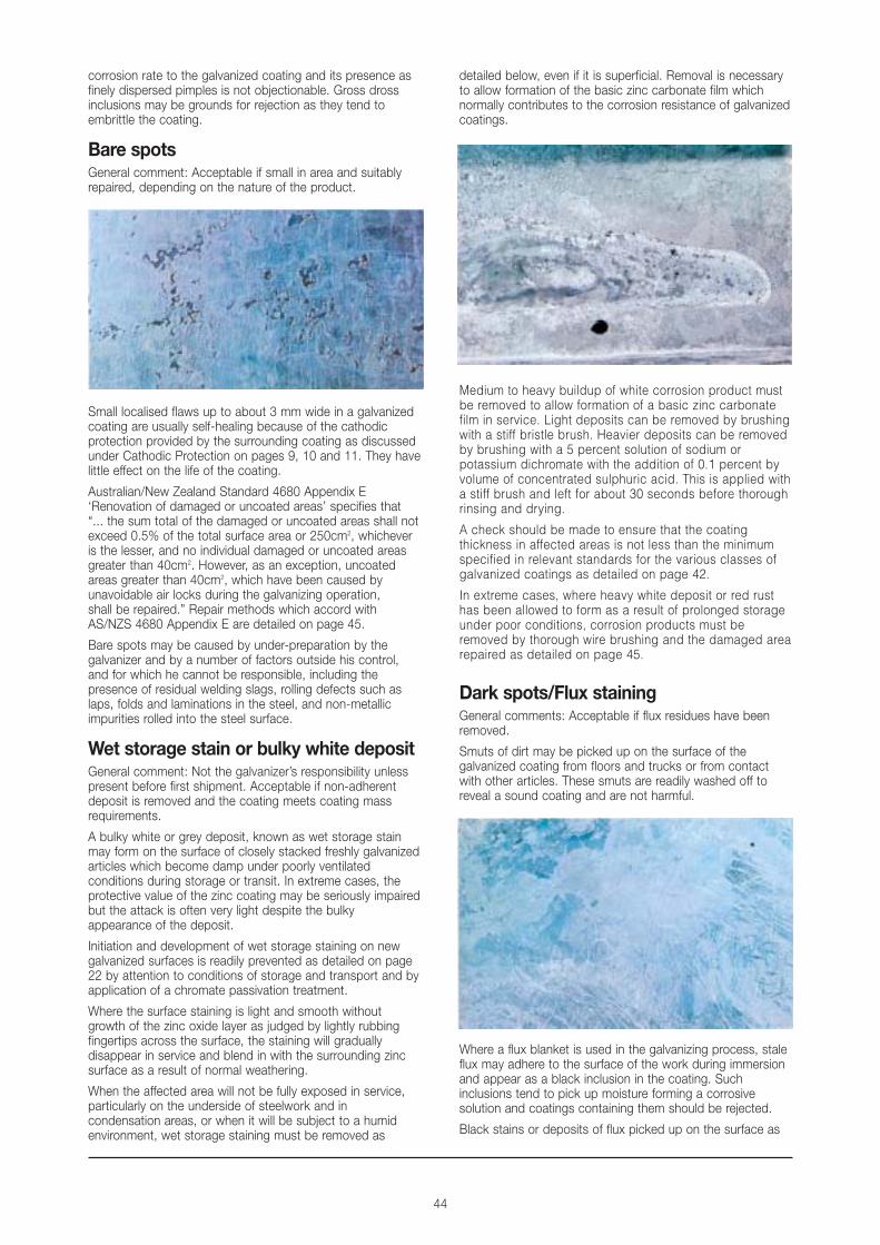
Wet storage stain or bulky white depositGeneral comment: Not the galvanizer’s responsibility unlesspresent before first shipment. Acceptable if non-adherentdeposit is removed and the coating meets coating massrequirements.
A bulky white or grey deposit, known as wet storage stainmay form on the surface of closely stacked freshly galvanizedarticles which become damp under poorly ventilatedconditions during storage or transit. In extreme cases, theprotective value of the zinc coating may be seriously impairedbut the attack is often very light despite the bulkyappearance of the deposit.
Initiation and development of wet storage staining on newgalvanized surfaces is readily prevented as detailed on page22 by attention to conditions of storage and transport and byapplication of a chromate passivation treatment.
Where the surface staining is light and smooth withoutgrowth of the zinc oxide layer as judged by lightly rubbingfingertips across the surface, the staining will graduallydisappear in service and blend in with the surrounding zincsurface as a result of normal weathering.
When the affected area will not be fully exposed in service,particularly on the underside of steelwork and incondensation areas, or when it will be subject to a humidenvironment, wet storage staining must be removed as
detailed below, even if it is superficial. Removal is necessaryto allow formation of the basic zinc carbonate film whichnormally contributes to the corrosion resistance of galvanizedcoatings.
Medium to heavy buildup of white corrosion product mustbe removed to allow formation of a basic zinc carbonatefilm in service. Light deposits can be removed by brushingwith a stiff bristle brush. Heavier deposits can be removedby brushing with a 5 percent solution of sodium orpotassium dichromate with the addition of 0.1 percent byvolume of concentrated sulphuric acid. This is applied witha stiff brush and left for about 30 seconds before thoroughrinsing and drying.
A check should be made to ensure that the coatingthickness in affected areas is not less than the minimumspecified in relevant standards for the various classes ofgalvanized coatings as detailed on page 42.
In extreme cases, where heavy white deposit or red rusthas been allowed to form as a result of prolonged storageunder poor conditions, corrosion products must beremoved by thorough wire brushing and the damaged arearepaired as detailed on page 45.
Dark spots/Flux stainingGeneral comments: Acceptable if flux residues have beenremoved.
Smuts of dirt may be picked up on the surface of thegalvanized coating from floors and trucks or from contactwith other articles. These smuts are readily washed off toreveal a sound coating and are not harmful.
Where a flux blanket is used in the galvanizing process, staleflux may adhere to the surface of the work during immersionand appear as a black inclusion in the coating. Suchinclusions tend to pick up moisture forming a corrosivesolution and coatings containing them should be rejected.
Black stains or deposits of flux picked up on the surface as

45
the object is withdrawn from galvanizing the bath do notwarrant rejection provided the underlying coating is soundand the deposit is removed.
Non-destructive testing for coating thicknessMagnetic gauges provide simple non-destructive testingmethods for coating thickness which are reliable and moreconvenient than the physical tests given under the variousnational standards listed on page 42.
Most gauges described are compact and can be used veryquickly. They give coating thickness readings over very smallareas and several readings should be taken and averaged.Uniformity as well as actual thickness can thus be easilychecked.
These magnetic gauges give reliable thickness readingsalthough some require frequent recalibration against non-magnetic coatings of known thickness and the makers’instructions are followed precisely. Accurate readings cannotbe obtained near edges of work and obvious peaks orirregularities in the coating should be avoided. Surfacecurvature, surface area and steel thickness all affect readingsin a predictable manner and allowances must be made.
Guidance on the use of these instruments is given in ASTME376-68T ‘Measuring coating thickness by magnetic field oreddy current (electromagnetic) test methods’.
Calibration curves for corrected readings and additionalinformation on these important non-destructive testingmethods are available free of charge from GalvanizersAssociation of Australia, 124 Exhibition Street, MelbourneVictoria 3000.
Minitector Model 156, Mitutoyo Neo-derm, andMinitest 500
The Minitector, Neo-derm and Minitest are small portablebattery powered units which operate by measuring thechanges in magnetic flux which occur when a magnet isseparated from contact with a ferrous metal.
Positector 2000
The Positector 2000 is an easy-to-use digital readout single-point coating measurement instrument which works on amagnetic field simulation principle. It needs no calibration andgives accurate results unaffected by shock, vibration, ortemperature.
Elcometer thickness gauge 101
This Elcometer contains a horseshoe magnet with its twopoles exposed and works on a magnetic induction principle.When the instrument is placed with both poles touching thesurface to be tested, changes of magnetic field broughtabout by variations in coating thickness move the bar magnetand the pointer. A mean thickness reading is given over thetwo points of contact.
The Inspector magnetic balance
The magnetic balance is based on the calibration of magneticattraction to the steel beneath a coating. The same principleis used by pull-off type gauges, but the magnetic balancegives a stable reading and incorporates a counterbalancedmagnet, allowing use in any position.
Pull-off type gauges
Simple pull-off magnetic thickness testing gauges such asthe Tinsley Pencil Gauge and the Elcometer Pull-off GaugeModel 157 are convenient and inexpensive, but requiregreater operator skill and in general do not provide theaccuracy of the gauges described above.
Reconditioning damagedsurfaces in galvanized steelWhen severe damage to the galvanized coating has occurredduring welding or as the result of rough handling in transportor erection, protection must be restored.
Small areas of the basis steel exposed through mechanicaldamage to galvanized coatings are protected from corrosioncathodically by the surrounding coating and may not needrepair, depending on the nature of the product and theenvironment to which it is exposed. Small exposed areasnormally have little effect on the life of the coating asdiscussed under ‘Bare spots,’ page 44 and ‘Cathodicprotection,’ page 11.
Repair methods
The coating repair methods detailed below are in accordancewith Australian/New Zealand Standard 4680 Appendix E‘Renovation of damaged or uncoated areas’.
Zinc rich paints. The application of an organic zinc richpaint is the most rapid and convenient method of repair. Thepaint should conform to AS/NZS 3750.9:1994 ‘Zinc richorganic priming paint’ applied in two coats by brush toprovide a total film thickness of 100 µm and for optimumperformance should contain not less than 92% zinc in thedried paint film.
Where colour matching is required aluminium paint may beapplied over the hardened zinc rich paint.
Zinc metal spraying. In certain circumstances, by prioragreement, zinc metal spraying may be used as a method ofcoating repair. The damaged area must be grit blasted toClass 3 followed by zinc metal spraying to a coatingthickness equivalent to that of the undamaged coating, andseal coated using an aluminium vinyl paint.