Embed Size (px)
Citation preview

Design Report Small Surface Large Combatant
(SSC) VT Total Ship Systems Engineering
SSC Large Variant Ocean Engineering Design Project
AOE 4065/4066 AOE 5314/5904
Fall 2009 – Spring 2010 Virginia Tech Team 5
Phillip Brock ___________________________________________ 276670
James Crabtree ___________________________________________ 24372
John Galterio ___________________________________________ 17788
Corey Kerns – Team Leader ___________________________________________ 17147
Chris Michie ___________________________________________ 18931
Kevin Poole ___________________________________________ 19588
Suzanna Ratcliffe ___________________________________________ 28248

SSC Large Variant Design – VT Team 5 Page 2
Executive Summary
MMR2 MMR1
Helo Hangar
Intake/ exhaust
AMRAMR
VLSIntake/ exhaust
Boat Ramp
57mm MK3
57mm Magazine
6122028364258668294106 This report describes the Concept Exploration and
Development of a Small Surface Combatant (SSC) for the United States Navy. This concept design was completed in a two-semester ship design course at Virginia Tech.
The SSC requirement is based on the Initial Capabilities Document (ICD). The ICD is available at Appendix A.
Concept Exploration trade-off studies and design space
exploration are accomplished using a Multi-Objective Genetic Optimization (MOGO) after significant technology research and definition. Objective attributes for this optimization are cost, risk (technology, cost, schedule and performance) and military effectiveness. The product of this optimization is a series of cost-risk-effectiveness frontiers which are used to select alternative designs and define Operational Requirements (ORD1) based on the customer’s preference for cost, risk and effectiveness.
The SSC design here-in is on the high end of the displacement
range outlined in the ICD. This Large SSC design allows for a much more robust AAW and ASW capabilities that can significantly contribute to Carrier Strike Group defense. The trade-off for these increased capabilities is a lower sustained speed (though still within the ICD range) and increased cost, both listed in the table to the right. The SSC is more comparable to the FFG in terms of operational capability and size but with more advanced systems, increased stability, less manning, better fuel consumption at endurance speed and has the ability to conduct independent operations as outlined in the ICD. A more complete comparison between the SSC and FFG is included.
Concept Development included hull form development and analysis for intact and damage stability, structural finite element analysis, propulsion and power system development and arrangement, general arrangements, machinery arrangements, combat system definition and arrangement, seakeeping analysis, cost and producibility analysis and risk analysis. The final concept design satisfies critical operational requirements in the ORD within cost and risk constraints.
Ship Characteristic Value LWL 121.5 m Beam 15.9 m Draft 5.3 m D10 11 m Lightship weight 4190 MT Full load weight 5040 MT Sustained Speed 30.1 knots Endurance Speed 20 knots Endurance Range 3589 nm
Propulsion and Power
CODAG Plant 2 LM2500’s & 2 CAT 3618
4 CAT 3516 SSDG’s 2 CPP’s
BHP 52,500 kW Personnel 65 OMOE (Effectiveness) 0.72 OMOR (Risk) 0.26
Ship Acquisition Cost $846 Million Lead
$665 Million Follow
Life-Cycle Cost $93 B Undiscounted $14.8 B Discounted
Combat Systems
32 Cell MK 41 VLS 57 mm Bofors Gun
AN/SPY – 1E Sband Radars MK XII AIMS IFF AN/SQS 56 Sonar
2 SH-60 Helos and Hangar 1 7m RHIB w/ Boat Bay
Mission Module 1.5 X LCS

SSC Large Variant Design – VT Team 5 Page 3
Table of Contents
EXECUTIVE SUMMARY.........................................................................................................................................................................................2
TABLE OF CONTENTS............................................................................................................................................................................................3
1 INTRODUCTION, DESIGN PROCESS AND PLAN................................................................................................................................5
1.1 INTRODUCTION.............................................................................................................................................5 1.2 DESIGN PHILOSOPHY, PROCESS, AND PLAN..................................................................................................5 1.3 WORK BREAKDOWN.....................................................................................................................................5 1.4 RESOURCES ..................................................................................................................................................5
2 MISSION DEFINITION ................................................................................................................................................................................6
2.1 CONCEPT OF OPERATIONS ............................................................................................................................6 2.2 PROJECTED OPERATIONAL ENVIRONMENT (POE) AND THREAT ..................................................................6 2.3 SPECIFIC OPERATIONS AND MISSIONS..........................................................................................................7 2.4 MISSION SCENARIOS ....................................................................................................................................7 2.5 REQUIRED OPERATIONAL CAPABILITIES ......................................................................................................8
3 CONCEPT EXPLORATION ......................................................................................................................................................................11
3.1 TRADE-OFF STUDIES, TECHNOLOGIES, CONCEPTS AND DESIGN VARIABLES .............................................11 3.1.1 Hull Form Alternatives .................................................................................................................11 3.1.2 Propulsion and Electrical Machinery Alternatives.......................................................................14 3.1.3 Automation and Manning Parameters ..........................................................................................20 3.1.4 Combat System Alternatives..........................................................................................................21 3.1.5 Modularity Alternatives ................................................................................................................28
3.2 DESIGN SPACE............................................................................................................................................35 3.3 SHIP SYNTHESIS MODEL.............................................................................................................................37 3.4 OBJECTIVE ATTRIBUTES.............................................................................................................................38
3.4.1 Overall Measure of Effectiveness (OMOE) ..................................................................................38 3.4.2 Overall Measure of Risk (OMOR) ................................................................................................45 3.4.3 Cost ...............................................................................................................................................46
3.5 MULTI-OBJECTIVE OPTIMIZATION .............................................................................................................47 3.6 OPTIMIZATION RESULTS AND INITIAL BASELINE DESIGN (VARIANT 137)..................................................47 3.7 IMPROVED BASELINE DESIGN – SINGLE OBJECTIVE OPTIMIZATION...........................................................49 3.8 ASSET FEASIBILITY STUDY.......................................................................................................................52
4 CONCEPT DEVELOPMENT (FEASIBILITY STUDY) ........................................................................................................................53
4.1 HULL FORM AND DECK HOUSE ..................................................................................................................53 4.1.1 Hullform........................................................................................................................................53 4.1.2 Deck House ...................................................................................................................................56
4.2 PRELIMINARY ARRANGEMENT (CARTOON)................................................................................................57 4.3 DESIGN FOR PRODUCTION ..........................................................................................................................59 4.4 SUBDIVISION ..............................................................................................................................................67
4.4.1 Hullform in HECSALV..................................................................................................................67 4.4.2 Transverse Subdivision, Floodable Length and Preliminary Tankage .........................................69 4.4.3 Loading Conditions and Preliminary Stability Analysis ...............................................................71
4.5 STRUCTURAL DESIGN AND ANALYSIS ........................................................................................................84 4.5.1 Geometry, Components and Materials..........................................................................................84 4.5.2 Loads.............................................................................................................................................91 4.5.3 Adequacy.......................................................................................................................................94 4.5.4 Revisions and Final Structural Design .........................................................................................99
4.6 POWER AND PROPULSION ...........................................................................................................................99 4.6.1 Resistance ...................................................................................................................................101 4.6.2 Propulsion Analysis – Endurance Range and Sustained Speed ..................................................103 4.6.3 Electric Load Analysis (ELA)......................................................................................................111
4.7 MECHANICAL AND ELECTRICAL SYSTEMS AND MACHINERY ARRANGEMENTS .......................................112
SSC Large Variant Design – VT Team 5 Page 4
4.7.1 Ship Service Power and Electrical Distribution .........................................................................115 4.7.2 Main and Auxiliary Machinery Spaces and Machinery Arrangement ........................................116
4.8 MANNING .................................................................................................................................................116 4.9 SPACE AND GENERAL ARRANGEMENTS ...................................................................................................118
4.9.1 Internal Arrangements ................................................................................................................119 4.9.2 Living Arrangements...................................................................................................................124 4.9.3 External Arrangements ...............................................................................................................127 4.9.4 Area and Volume.........................................................................................................................128
4.10 WEIGHTS, LOADING AND STABILITY ........................................................................................................128 4.10.1 Lightship Weights........................................................................................................................128 4.10.2 Loads and Loading Conditions ...................................................................................................128 4.10.3 Final Hydrostatics and Intact Stability .......................................................................................129 4.10.4 Damage Stability.........................................................................................................................132
4.11 SEAKEEPING, MANEUVERING AND CONTROL ...........................................................................................133 4.12 COST AND RISK ANALYSIS .......................................................................................................................133
5 CONCLUSIONS AND FUTURE WORK................................................................................................................................................138
5.1 ASSESSMENT ............................................................................................................................................138 5.2 FUTURE WORK .........................................................................................................................................139 5.3 CONCLUSIONS ..........................................................................................................................................140
THE FINALIZED SSC LARGE DESIGN MEETS ALL OF THE MAJOR KPP’S CONTAINED IN TABLE 46, AND WOULD PROVE TO BE A EFFECTIVE FROM A COST AND OPERATIONAL PERSPECTIVE. THIS DESIGN IS BASED ON THE PROVEN FFG 7 CLASS PARENT HULL FORM, AND THE VARIOUS SYSTEMS INSTALLED ON THE SHIP PROVIDE A LOW RISK SOLUTION TO THE US NAVY. THE MECHANICAL CODAG PLANT IS A PROVEN DESIGN THAT HAS BEEN USED IN THE PAST ON FUTURE SURFACE COMBATANTS. IT ENABLES THE VESSEL TO OPERATE IN THE ENDURANCE SPEED REGIME WITH ONLY THE EFFICIENT PROPULSION DIESEL GENERATORS ONLINE, BUT HAS THE ABILITY TO ACHIEVE RELATIVELY HIGH SUSTAINED SPEEDS WITH THE DIESELS AND GAS TURBINES ONLINE. .............................140
THE VESSEL ALSO INCLUDES MANY FEATURES THAT WILL HELP IMPROVE PRODUCIBILITY AND KEEP INITIAL ACQUISITION COSTS DOWN. THIS WILL ALLOW THE SHIP TO BE PURCHASED IN SUFFICIENT NUMBERS TO MEET THE DEMANDS OF THE FLEET.......................................................................................................................................................................140
THROUGH THE USE OF THE SOPHISTOCATED COMBAT SYSTEMS INSTALLED ON THE SHIP IN CONJUNCTION WITH THE ABILITY TO CARRY DEPLOYABLE MISSION MODULES WILL ENABLE THE SSC LARGE TO MEET THE COMPLEX OPERATIONAL MISSION REQUIREMENTS OUTLINED IN THE ICD. REFERENCES ....................................................................140
REFERENCES ........................................................................................................................................................................................................141
APPENDIX A – INITIAL CAPABILITIES DOCUMENT (ICD) ....................................................................................................................142
APPENDIX B– ACQUISITION DECISION MEMORANDUM (ADM).........................................................................................................145
APPENDIX C– CAPABILITIES DEVELOPMENT DOCUMENT (CDD) ....................................................................................................146
APPENDIX D – MACHINERY EQUIPMENT LIST (MEL) ...........................................................................................................................152
APPENDIX E - WEIGHTS AND CENTERS......................................................................................................................................................156
APPENDIX F – SSCS SPACE SUMMARY ........................................................................................................................................................159
APPENDIX G – POWER AND PROPULSION ANALYSIS ............................................................................................................................164

SSC Large Variant Design – VT Team 5 Page 5
1 Introduction, Design Process and Plan
1.1 Introduction
This report describes the concept exploration and development of a Small Surface Combatant (SSC) for the United States Navy. The SSC requirement is based on the SSC Initial Capabilities Document (ICD), and Virginia Tech SSC Acquisition Decision Memorandum (ADM), Appendix A and Appendix B. This concept design was completed in a two-semester ship design course at Virginia Tech. SSC must perform Anti-surface and subsurface warfare, Homeland Defense, ISR, Maritime Interdiction, anti-terrorism protection, provide support for special forces operations, logistics, mine warfare, and anti-air warface in Carrier Strike Groups (CSGs), Expeditionary Strike Groups (ESGs), Surface Action Groups (SAGs), and Independent Ops (IOs) It must be between 2000 and 8000 MT in displacement and must be cost effective, meaning it must cost less than $300M with an absolute ceiling of $400M. This ship will be placed to perform the missions listed above in open-ocean and littoral waters with high target densities. Therefore, SSC will function in wave heights up to SS7 and survive in SS9.
1.2 Design Philosophy, Process, and Plan
Our design project consists of two main parts: Concept and Requirements Exploration (C&RE) and Required Operational Capabilities (ROCs), or what missions the boat will be carrying out over its lifetime. C&RE provides a consistent format and methodology for making affordable multi-objective acquisition decisions and trade-offs in a non-dominated design space. It also provides practical and quantitative methods for measuring mission effectiveness and risk, as well as methods to search the design space for optimal concepts. C&RE starts with an ICD/ADM which is used to develop detailed CONOPS and Concept Development. ROCs are evaluated to create Measures of Performance (MOP) which are used to evaluate the overall effectiveness of the designs that they create. Using these MOPs, the design team identifies Design Variables (DVs), or the basic characteristics that the ship will need to accomplish all missions requirements set forth by the Navy. A Non-Dominated, design space is then created. This space (graph) allows the design team to pick the most suitable design based on the cost and the Overall Measure of Effectiveness (based on risk and the ROCs). Once the design is picked, the design team can put the details, such as mechanical systems, combat systems, electrical systems and drives, manning, and modularity.
1.3 Work Breakdown
SSC Team 6 consists of six students from Virginia Tech. Each student is assigned areas of work according to his or her interests and special skills as listed in Table 1.
Table 1 - Work Breakdown Name Specialization
Chaz Henderson Mission and Mission Effectiveness Corey Kerns Hull, Mechanical, and Electrical, Risk Ryan Kneifel Combat Systems, Manning, Cost Kevin Poole Modularity John Galterio Space and Weight Corey Kerns Synthesis Model and Optimization
1.4 Resources
Computational and modeling tools used in this project are listed in Error! Reference source not found..
Table 2 - Tools Analysis Software Package
Arrangement Drawings Rhino
SSC Large Variant Design – VT Team 5 Page 6
Hull form Development Rhino/ASSET Hydrostatics HECSALV Resistance/Power NavCAD Ship Motions SWAN, SMP Ship Synthesis Model Model Center/ASSET Structure Model MAESTRO
2 Mission Definition
The SCC requirement is based on the SSC Mission Need Statement (MNS), and Virginia Tech SSC Acquisition Decision Memorandum (ADM), Appendix A and Appendix B with elaboration and clarification obtained by discussion and correspondence with the customer, and reference to pertinent documents and web sites referenced in the following sections.
2.1 Concept of Operations
The SSC class will be able to operate as a scalable modular family of SSC ships with capabilities sufficient to satisfy the full range of specified SSC capability requirements using interchangeable, networked mission modules, and with the option of more capable AAW sensors and weapons could also be modular, but would be added in construction as a SSC variant or in a major availability using a hull plug, modular deckhouse, or modular mast(s). There variants would be able to contribute significant area AAW support for ESGs or as part of CSGs.
SSC will also be used in support of CSG/ESGs. Two to three SSC ships could be assigned to each strike group with MSCs and a carrier or amphibious ship. Their mission configuration would complement the other strike group combatants. Larger SSCs may be able to contribute to CSG and ESG area AAW defense. Tailored mission configurations could include defense against mine threats, littoral ASW threats, and small boat threats using distributed off-board systems. High speed and agility could provide tactical advantage.
SSC Surface Action Groups (SAGs) will also be utilized. They will operate as a force of networked, dispersed SSCs, providing collective flexibility, versatility and mutual support. SSC and MSC SAGs could provide defense against mine threats, littoral ASW threats, and small boat threats ahead of larger CSGs/ESGs including first-response capability to anti-access crises. High speed and agility should provide a significant tactical advantage.
During SSC Independent Operations, SSC would perform inherent (mobility) mission tasking in known threat environments including defense against mine threats, littoral ASW threats, and small boat threats. Rapid response to contingency mission tasking could provide OTH Targeting, reach-back for mission planning, insertion/extraction of USMC, Army, SOF personnel, and movement of cargo/personnel. SSC could provide ISR ahead of CSG/ESG operations and maritime interdiction/interception operations, overseas or in support of homeland defense, possibly as USCG assets.
Ship deployments could be extended with rotating crews alternately returning to CONUS. Interchangeable, networked mission modules could be changed in 2-3 days, in theater, to support force needs and changing threats. Some SSCs could be configured with more capable AAW sensors and weapons that could also be modular, but require extended availability for upgrade or change-out. Hull plugs, modular deckhouse and modular mast options should be considered for these SSC variants. They would be able to contribute significant area AAW support for ESGs or as part of CSGs.
2.2 Projected Operational Environment (POE) and Threat
SSC will be used for world-wide operation in cluttered, littoral environments or constrained bodies of water with smaller scales relative to open ocean warfare. These environments create an increased difficulty of detecting and successfully prosecuting targets. It will also be used in open ocean environments as part of CSGs and ESGs, so it must be able to withstand Sea States 1 to 9. The threats that SSC will face are asymmetric, overlapping, and commercially available. They include threats from nations with a major military capability, or the demonstrated interest in acquiring such a capability. Major military capabilities include land, surface, and air launched cruise missiles, diesel submarines, land-attack cruise missiles, and theatre ballistic missiles. It will also face threats from smaller nations who support, promote, and perpetrate activities that cause regional instabilities detrimental to international security and/or have the potential development of nuclear weapons. These threats could be seen in small diesel/electric submarines, land-based air assets, chemical/biological/ radiological weapons, fixed and mobile SAM sites, swarming small boats, and sophisticated sea mines.

SSC Large Variant Design – VT Team 5 Page 7
2.3 Specific Operations and Missions
The SSC will be capable of performing Underway Replenishment operations, cooperatively detect, engage, and destroy enemy aircraft with nearby AEGIS units, conduct precision missile strikes, engage and kill enemy patrol craft and small boats, perform ISR of the enemy from littoral waters, map and neutralize enemy minefields, avoid or eliminate enemy submarines using LAMPs/Sonar, conduct shore bombardment in support of amphibious assaults with ground troops, destroy incoming enemy cruise missiles, and map enemy coastlines if needed
2.4 Mission Scenarios
Mission scenarios for the primary SSC missions are provided in Table 3 through Table 6. These missions include the support of SAGs, ESGs, and CSGs as well as Independent Operations (IO).
Table 3 – SAG Mission Scenario
Day Mission Scenario for Surface Action Group (SAG) 1-8 Transit from Home Port to forward base. 9-12 Refuel and replenish 13-20 Transit from Forward base to area of hostility 21 Avoid/Eliminate enemy submarine 22-26 Cooperatively, with Aegis unit, detect, engage and destroy enemy aircraft 26-27 Execute pre-programmed precision missile strike on inland airfield 28 Conduct precision missile strike on enemy Naval facility 29 Engage and kill enemy patrol crafts with .50-cal machine gun and harpoon missile 30-36 Receive new targeting information and conduct missile strike on update targets 37 Cooperatively, with Aegis unit, detect, engage, and destroy incoming enemy cruise missile on ARG unit 38 Detach from SAG 39-54 Perform ISR of enemy from Littoral Waters (at least 25nm from ESG). 55 Return to SAG 56-60 Receive new targeting information and conduct missile strike on update targets 58-60 Conduct precision strikes in support of ground troops
Table 4 - ESG Mission Scenario for SSC in MCM Configuration
Day Mission Scenario for Expeditionary Strike Group (ESG) - MCM Configuration 1-8 Transit from Home Port to forward base. 9-12 Refuel and replenish 13-20 Transit from Forward base to area of hostility 21 Avoid/Eliminate enemy submarine 22-26 Map and neutralize enemy minefield to allow access to amphibious landing point 26-27 Execute pre-programmed precision missile strike on inland target 28 Conduct shore bombardment in support of amphibious landing 29 Engage and kill enemy patrol crafts with .50-cal machine gun and harpoon missile 30-36 Receive new targeting information and conduct missile strike on update targets 37 Cooperatively, with Aegis unit, detect, engage, and destroy incoming enemy cruise missile on ESG unit 38 Detach from ESG 38-48 Perform ISR of enemy from littoral waters (at least 25nm from ESG) 43-48 Search for enemy mines. Neutralize them if found. 49 Return to ESG 49-56 Map and neutralize enemy minefield to allow access to second amphibious landing point 56-60 Receive new targeting information and conduct missile strike on update targets 58-60 Conduct precision strikes in support of ground troops
Table 5 - CSG Mission Scenario for SSC in AAW Configuration
Day Mission Scenario for Carrier Strike Group (CSG) - AAW Configuration

SSC Large Variant Design – VT Team 5 Page 8
1-8 Transit from Home Port to forward base. 9-12 Refuel and replenish 13-20 Transit from Forward base to area of hostility 21 Search/Eliminate enemy submarine with LAMPs and Sonar 22-26 Cooperatively, with Aegis unit, detect, engage and destroy enemy aircraft 26-27 Execute pre-programmed precision TLAM missile strike on inland airfield 28 Conduct precision missile strike on enemy Naval facility 29 Perform ISR in order to facilitate the launching of aircraft from carrier 30-36 Receive new targeting information and conduct missile strike on update targets 37 Cooperatively, with Aegis unit, detect, engage, and destroy incoming enemy cruise missile on SAG unit 38 Detach from CSG 39-54 Perform ISR of enemy airfield from Littoral Waters (at least 25nm from SAG). 55 Return to CSG 56-60 Receive new targeting information and conduct missile strike on update targets 58-60 Conduct precision strikes in support of ground troops
Table 6 - IO Mission Scenario for SSC in MCM Configuration
Day Mission Scenario for SSC Independent Operations - MCM Configuration 1-8 Transit from Home Port to forward base. 9-12 Refuel and replenish 13-20 Transit from Forward base to area of hostility 21 Search/Eliminate enemy submarine with LAMPs and Sonar 22-26 Map and neutralize enemy minefield. Conduct ISR 26-27 Execute pre-programmed precision TLAM missile strike on inland airfield 28 Conduct precision missile strike on enemy Naval facility 29 Perform ISR in order to facilitate the launching of aircraft from carrier 30-36 Receive new targeting information and conduct missile strike on update targets 37-44 Map enemy coastline. Neutralize any enemy mines that are found. 45-54 Perform ISR of enemy airfield and naval facility 56-60 Receive new targeting information and conduct missile strike on update targets 58-60 Conduct precision strikes in support of ground troops
2.5 Required Operational Capabilities
In order to support the missions and mission scenarios described in Section 2.4, the capabilities listed in Error! Reference source not found. are required. Each of these can be related to functional capabilities required in the ship design, and, if within the scope of the Concept Exploration design space, the ship’s ability to perform these functional capabilities is measured by explicit Measures of Performance (MOPs).
Table 7 - List of Required Operational Capabilities (ROCs)
ROCs Description
AAW 1 Provide anti-air defense AAW 1.1 Provide area anti-air defense AAW 1.2 Support area anti-air defense AAW 1.3 Provide unit anti-air self defense AAW 2 Provide anti-air defense in cooperation with other forces AAW 5 Provide passive and soft kill anti-air defense AAW 6 Detect, identify and track air targets AAW 9 Engage airborne threats using surface-to-air armament
AMW 6 Conduct day and night helicopter, Short/Vertical Take-off and Landing and airborne autonomous

SSC Large Variant Design – VT Team 5 Page 9
ROCs Description vehicle (AAV) operations
AMW 6.3 Conduct all-weather helo ops
AMW 6.4 Serve as a helo hangar
AMW 6.5 Serve as a helo haven
AMW 6.6 Conduct helo air refueling
AMW 12 Provide air control and coordination of air operations
AMW 14 Support/conduct Naval Surface Fire Support (NSFS) against designated targets in support of an amphibious operation
AMW 15 Provide air operations to support amphibious operations
ASU 1 Engage surface threats with anti-surface armaments
ASU 1.1 Engage surface ships at long range
ASU 1.2 Engage surface ships at medium range
ASU 1.3 Engage surface ships at close range (gun)
ASU 1.4 Engage surface ships with large caliber gunfire
ASU 1.5 Engage surface ships with medium caliber gunfire
ASU 1.6 Engage surface ships with minor caliber gunfire
ASU 1.9 Engage surface ships with small arms gunfire
ASU 2 Engage surface ships in cooperation with other forces
ASU 4 Detect and track a surface target
ASU 4.1 Detect and track a surface target with radar
ASU 6 Disengage, evade and avoid surface attack
ASW 1 Engage submarines
ASW 1.1 Engage submarines at long range
ASW 1.2 Engage submarines at medium range
ASW 1.3 Engage submarines at close range
ASW 4 Conduct airborne ASW/recon
ASW 5 Support airborne ASW/recon
ASW 7 Attack submarines with antisubmarine armament
ASW 7.6 Engage submarines with torpedoes
ASW 8 Disengage, evade, avoid and deceive submarines
CCC 1 Provide command and control facilities CCC 1.6 Provide a Helicopter Direction Center (HDC) CCC 2 Provide own unit Command and Control CCC 3 Maintain data link capability CCC 4 Provide communications for own unit CCC 6 Relay communications CCC 9 Perform cooperative engagement CCC 21 Provide support services to other units

SSC Large Variant Design – VT Team 5 Page 10
ROCs Description FSO 3 Conduct towing/search/salvage rescue operations FSO 5 Conduct SAR operations FSO 6 Provide explosive ordnance disposal services FSO 7 Conduct port control functions FSO 8 Provide routine health care FSO 9 Provide first aid assistance FSO 10 Provide triage of casualties/patients FSO 11 Provide medical/surgical treatment for casualties/patients FSO 12 Provide medical, surgical, post-operative and nursing care for casualties/ patients FSO 13 Provide medical regulation, transport/evacuation and receipt of casualties and patients FSO 14 Provide routine and emergency dental care FSO 16 Support/conduct intelligence collection INT 1 Provide intelligence INT 2 Conduct surveillance and reconnaissance INT 3 Process surveillance and reconnaissance information INT 8 Disseminate surveillance and reconnaissance information INT 9 Provide intelligence support for non-combatant evacuation operation (NEO) INT 15 Transfer/receive cargo and personnel LOG 2 Provide airlift of cargo and personnel LOG 6 Conduct mine neutralization/destruction MIW 3 Conduct mine avoidance MIW 4 Conduct magnetic silencing (degaussing, deperming) MIW 6 Maintain magnetic signature limits MIW 6.7 Steam to design capacity in most fuel efficient manner MOB 1 Support/provide aircraft for all-weather operations MOB 2 Prevent and control damage MOB 3 Counter and control NBC contaminants and agents MOB 3.2 Maneuver in formation
MOB 5 Perform seamanship, airmanship and navigation tasks (navigate, anchor, mooring, scuttle, life boat/raft capacity, tow/be-towed)
MOB 7 Replenish at sea MOB 10 Maintain health and well being of crew
MOB 12 Operate and sustain self as a forward deployed unit for an extended period of time during peace and war without shore-based support
MOB 13 Operate in day and night environments MOB 16 Operate in heavy weather MOB 17 Operate in full compliance of existing US and international pollution control laws and regulations MOB 18 Provide upkeep and maintenance of own unit NCO 3 Conduct maritime law enforcement operations NCO 19 Conduct sensor and ECM operations SEW 2 Conduct sensor and ECCM operations SEW 3 Conduct coordinated SEW operations with other units SEW 5 Support/conduct multiple cruise missile strikes

SSC Large Variant Design – VT Team 5 Page 11
3 Concept Exploration
Chapter 3 describes Concept Exploration. Trade-off studies, design space exploration and optimization are accomplished using a Multi-Objective Genetic Optimization (MOGO).
3.1 Trade-Off Studies, Technologies, Concepts and Design Variables
Available technologies and concepts necessary to provide required functional capabilities are identified and defined in terms of performance, cost, risk and ship impact (weight, area, volume, power). Trade-off studies are performed using technology and concept design parameters to select trade-off options in a multi-objective genetic optimization (MOGO) for the total ship design. Technology and concept trade spaces and parameters are described in the following sections.
3.1.1 Hull Form Alternatives
3.1.1.1 Hull Form Technology Selection Process
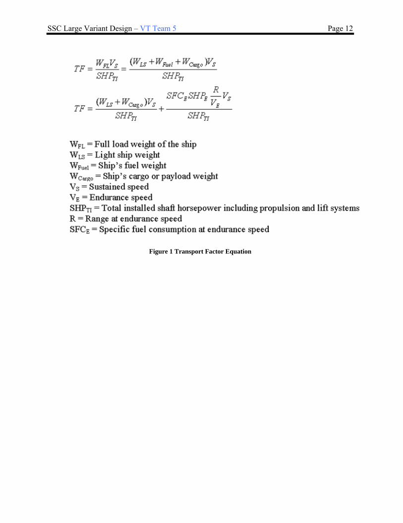
The Transport Factor methodology is used to identify alternative hull-form type(s). Important parameters used to calculate transport factor are payload or cargo weight, required sustained speed, endurance speed and range. Design lanes are used to specify hull-form design parameter ranges for the design space. Hull Form performance metrics are considered during the selection process. These metrics include but are not limited too available deck area, radar cross-section, cost, structural efficiency and seakeeping characteristics. Hull form modeling alternatives have also been considered. Transport Factor equations and examples are shown in Figure 1-Figure 3.
SSC Large Variant Design – VT Team 5 Page 12
Figure 1 Transport Factor Equation

SSC Large Variant Design – VT Team 5 Page 13
Figure 2 Transport Factor Example for Hull Type
3.1.1.2 Transport Factor Estimate for SSC
Transport Factor for the SSC was calculated by using the range of characteristic possibilities stated in the ICD. These ranges include a scalable modular ship from 2000-5000MT, sustained speed 30-45kts, SHP 40-70MW and an endurance range of 4000-5000nm. The resulting transport factor for the SSC ranged from 5 to 25 averaging 13.5. This Transport Factor suggests planing, semi-planing, or displacement hulls which include possibilities for monohull or multi-hull vessels. The large range for transport factor required separate analyses for a 30-35 knot ship and a 40-45 knot ship. Our team was assigned the 30-35 knot large end of the design space with displacement extended above the original range to 4000-8000MT.
Ship or Concept # Type Speed TF Power Range Payload Displacement
(knots) (SHP) (n.mi) (LT) (LT)
Destriero 19 SP 50 7.32 51675 2000 260 1100
Fastship-Atlantic TG-770 (design) 20 SP (Design) 42 18.33 480000 4800 13600 30480
SOCV (Fastship-Atlantic daughter hull design)
21 SP (Design) 36.5 30.95 320000 4000 10000 39475
Aker Finnyards HSS 1500 22 Disp 40 13.02 95000 500 1300 4500
Aker Finnyards Swath 2000 (design) 23 Disp (Design) 40 13.2 125000 1000 2000 6000
INCAT 130m (design) 24 Disp (Design) 63 18.35 118008 4300 2000 5000
Sumitomo Monohull (design) 25 Disp (Design) 50 30.18 266300 5000 1000 23400
SS United States - As Built 26 Disp 37.25 48.49 240000 10000 5750 45450
SS United States 1997 (design) 27 Disp (Design) 39.5 48.85 240000 10000 5750 43178
1500' Slender Monohull (design) 28 Disp (Design) 50 43.86 525000 10000 20000 67000
DDG51 29 Disp 32 18.72 100000 4500 800 8500
FFG7 30 Disp 28 21.68 40000 6000 350 4500
Figure 3 - Transport Factor for a Selection of Hulls

SSC Large Variant Design – VT Team 5 Page 14
3.1.1.3 Important Hullform Characteristics
There are other important hullform characteristics besides transport factor that were used to decide the final hullform. These include a hull with sufficient weight and space margin to have interchangeable modules, enough deck space for a Helo Deck area and hangar for 1-2 SH-60 and/or 1-2 VTUAV’s and the ability to have stern or side launch and recovery for surface and underwater vehicles. The hullform also requires good seakeeping abilities which could include flare or hybrid hullform designs. Another consideration is the producibility of the hullform to fulfill a possible fleet of 50 SSC vessels.
Specific requirements include a moderate speed hullform for the sustained speed of 30-35 knots with a transport factor range of 13-25 which suggests a displacement monohull. Also considered is ample large object space for equipment such as VLS which also would typically require a monohull. The final requirement in large deck space to support helo or UAV operations and space for launch and recovery of other waterborne vehicles which could suggest either a multihull or monohull form. It was decided that a displacement monohull design best meets all of these requirements. 4000-8000 is a frigate sized ship.
3.1.1.3.1 Design Lanes (30-35kt SSC)
Typical frigate hullform design lanes are listed in Table 8. We will extend the displacement range to 8000MT
and investigate the design space for 4000-8000MT listed in Table 9.
Table 8 - Frigate Design Lanes
Design Lane Range displacement 2000-5000 MT TF 12 – 25.2 L/B 7.6 – 8.5 B/T 3.2 – 3.4 Cp .54-.6 Cx .75-.84
Table 9 - Hullform Design Space Summary (30-35kt SSC)
Design Lane Range Hullform Type Monohull Displacement 4000-8000MT L 100-140 m B/ T 2.9-3.2 L/B 7-10 L/D 11-14 Cp .57-.63 Cx .76-.85
We will generate our baseline hullforms spanning this design space using ASSET DDG-51 parent boundary
curves. Hull volume, weight and performance RSMs will also be generated using ASSET.
3.1.2 Propulsion and Electrical Machinery Alternatives
We began the process of creating propulsion and electrical machinery alternatives by developing machinery general requirements and guidelines based on the IDC and ADM. We selected viable machinery alternatives based on these guidelines and developed an alternative machinery selection hierarchy. Data was gathered and developed for viable machinery alternatives by using manufacturer data, modeling each machinery alternative in an ASSET baseline design and collecting all data in a propulsion alternative data base (Excel file). This file was used to update our ship synthesis propulsion module. A machinery system trade off was performed as part of total ship synthesis and optimization.

SSC Large Variant Design – VT Team 5 Page 15
3.1.2.1 Machinery Requirements
Based on the ADM and Program Manager guidance, pertinent propulsion plant design requirements are summarized as follows:
General Requirements – The design required a range of 4000-5000 nautical miles at an endurance speed of 20 knots. .Navy qualified and grade A shock certified gas turbines were considered in the alternatives as a design variable. We also considered low IR signature and possible CODAG (see Figure 4-Figure 5) options for endurance. Design for continuous operation using distillate fuel in accordance with ASTM D975, Grade 2-D; ISO 8217, F-DMA, DFM (NATO Code F-76 and JP-5 (NATO Code F-44).
Figure 4 - CODAG sample arrangement for 2 Diesels and 1 Gas turbine connected to two shafts
Figure 5 - CODAG sample arrangement for 1 Gas Turbine and 1 Diesel per shaft
Sustained Speed and Propulsion Power – The alternatives span a 40-70MW SHP power range. We considered only designs that met a minimum sustained speed of 30 knots in the full load condition, calm water, and clean hull using no more than 80% of the installed engine rating (MCR) of main propulsion engines or motors. The goal speed for the SSC is 35 knots.
Ship Control and Machinery Plant Automation – Control automation requirements include an integrated bridge

SSC Large Variant Design – VT Team 5 Page 16
system that encompasses integrated navigation, radio communications, interior communications, and ship maneuvering equipment and systems. This integrated bridge system must comply with the ABS Guide for One Man Bridge Operated (OMBO) Ships. Machinery plant automation must comply with ABS ACCU requirements for periodically unattended machinery spaces. Other automation requirements include continuously monitored auxiliary systems, electric plant and damage control systems monitored from the SCC, MCC and Chief Engineer’s office and control systems from the MCC and local controllers.
Propulsion Engine and Ship Service Generator Certification – Because of the criticality of propulsion and ship service power to many aspects of the ship’s mission and survivability, this equipment may be grade A shock certified and Navy qualified by IOC.
3.1.2.2 Machinery Plant Alternatives
High speed requires high power density so we considered gas turbine engines and epicyclic (planetary) reduction gears with the possibility of CODAG for endurance. The power requirement was satisfied with 2 main engines with a power range of 20000-36000 kW each. Propulsion efficiency at 30-35 knots for displacement/semi-displacement hulls suggests standard CPP and shafting. We considered mechanical drive and IPS along with the possible combination of the two systems. With gas turbine mains we considered Diesel Gen Sets to meet the 4000-6000nm endurance range requirements.
IPS machinery plants with DC Bus, zonal distribution and permanent magnet motors were also alternatives. The IPS alternatives provide arrangement and operational flexibility, future power growth, improved fuel efficiency and survivability with moderate weight and volume penalties.
Data for Trade-Off studies was collected by creating alternative propulsion plants in a baseline ship using ASSET. Machinery plant alternatives are listed in Figure 6 with specific data in Table 10 and Table 11 with individual components displayed in Figure 7-Figure 13.
SSC Propulsion Options
Mechanical Drive
1 shaft, 2xLM2500+ w/LTDR gear, 2MW SPU
1 shaft: 2xMT30, w/LTDR gear, 2MW SPU
1 shaft: 2xLM2500+ & 1xCAT 3616, w/LTDR gear (CODAG), 2MW SPU
2 shafts: 2xLM2500+ w/ epicyclic gears
2 shafts: 2xMT30 w/ epicyclic gears
2 shafts: 2xLM2500+ & 2xCAT 3616 w/LTDR gears (CODAG)
SSDG options
3xCAT3512B SSDGs
4xCAT3512B SSDGs
3xCAT3516B SSDGs
4xCAT3516B SSDGs
Full IPS
2 shafts: PMMs, 4160 VAC, DC ZEDS, 2xLM2500+ PGMs
2 shafts: PMMs, 4160 VAC, DC ZEDS, 2xMT30 PGMs
2 shafts: PMMs, 4160 VAC, DC ZEDS, 3xLM2500+ PGMs
2 shafts: PMMs, 4160 VAC, DC ZEDS, 3xMT30 PGMs
SPGM options
2xCAT3512B (AC Sync) SPGMs
2xCAT3516B (AC Sync) SPGMs
2xPEM 2 MW Fuell Cells SPGMs
2xPEM 3 MW Fuell Cells SPGMs
Figure 6 - Machinery Plant Alternatives

SSC Large Variant Design – VT Team 5 Page 17
Table 10 - Propulsion Plant Data
Table 11 - Electrical Plant Data
Figure 7 - LM2500+

SSC Large Variant Design – VT Team 5 Page 18
Figure 8 - MT30
Figure 9 - CAT 3616B
Figure 10 - CAT 3612B

SSC Large Variant Design – VT Team 5 Page 19
Figure 11 - CAT 3516/3512B Gen Sets
Figure 12 - Integrated Power System

SSC Large Variant Design – VT Team 5 Page 20
Figure 13 - Zonal Survivability
3.1.3 Automation and Manning Parameters
Manning is the greatest cost over a ships lifetime. The cost of manning is sixty percent of the Navy’s budget. The largest expense incurred over a ship’s lifetime is the crew. One of the issues with manning is that the manpower on a vessel can be put in harms way. Damage control and firefighting are managed by manpower with a high risk to the personnel. Job enrichment, computer literacy, and response time are all human factors that can cause the death of personnel. Another problem is the background of each sailor. Each background comes with different cultures and traditions that must be addressed in tight living spaces. The manning triad that includes watch standing, maintenance, and damage control requires a significant amount of manning. Recent developments in technology has allowed for a reduction in manpower over most areas of a ship. That said it is important in early design phases to try and reduce the number of personnel on a ship. The use of computers or machinery in place of personnel is automation. Automation can be applied to many areas of a ship. Firefighting can be replaced by automated robot arms for fire suppression. These arms can sense heat or smoke and if used with an automated sprinkler system they can keep personnel away from harm. The response time can be reduced by using an automated system. Without the need for extra personnel during a fire manning is reduced. Other technologies are available to help reduce manning. Watch standing technology can assist an individual with automated route planning, electronic charting, navigation, collision avoidance and electronic log keeping. Video conferencing allows for the knowledge of expert personnel without having them onboard. Computer systems can be learned on shore rather than having to have hands on experience. These tutorials can be replayed if one forgets exactly how to perform a task. Using these computer systems helps make a ship paperless. It keeps administration personnel on shore while allowing them to perform their duties electronically.

SSC Large Variant Design – VT Team 5 Page 21
Figure 1 – Level of Automation vs. Acquisition Cost
A manning Response Surface Model (RSM) allows for the calculation of required manning. ISMAT (Integrated Simulation Manning Analysis Tool) is used to develop scenarios to test ability of the crew. It dynamically allocates each task to a crew member. A size and make up of crew is optimized for four different goals: cost, crew size, different jobs, and workload. The total crew size is calculated using the formula below:
2
22
33
2
**210.***485.
***413.**684.**341.
***294.*52.8*147.**08.2
*85.59*29.11*09.6*06.8249.374
LWLCompCCCLWLCompCCCMAINTCCC
LevAutoPSYSLWLCompPSYSMAINTASuwLevAuto
PSYSASuWLevAutoPSYSLWLCompPSYS
LevAutoLWLCompMAINTLevAutoNT
Figure 14 - “Standard” Manning Calculation
In concept exploration it is difficult to deal with automation manning reductions explicitly, so a ship manning and automation factor is used. This factor represents reductions from “standard” manning levels resulting from automation. The manning factor, CAUTO, varies from 0.5 to 1.0. It is used in the regression based manning equations shown in
Figure 15. A manning factor of 1.0 corresponds to a “standard” fully-manned ship. A ship manning factor of 0.5 results in a 50% reduction in manning and implies a large increase in automation. The manning factor is also applied using simple expressions based on expert opinion for automation cost, automation risk, damage control performance and repair capability performance. Manning calculations are shown in
Figure 15. A more detailed manning analysis is performed in concept development.
Figure 15 - “Standard” Manning Calculation
3.1.4 Combat System Alternatives
Combat systems are grouped in sections. These sections include but are not limited to: Anti-Air Warfare (AAW), Anti-Submarine Warfare (ASW), Anti-Surface Warfare (ASUW), and Light Airborne Multi-Purpose System (LAMPS).

SSC Large Variant Design – VT Team 5 Page 22
3.1.4.1 AAW
1. Warfighting System 2. Options
Option 1) AN/SPY-1E MFR – Multi Mode Radar , ICMS, AIMS IFF,AIEWS, Combat DF, 2xMK137 LCHR SRBOC/NULKA
Option 2) SEAPAR MFR, ICMS, AIMS IFF, AIEWS, Combat DF, 2xMK137 LCHR SRBOC/NULKA
3. AAW system alternatives
Option 3) EADS TRS-3D C-band radar, AIMS IFF, 2xSRBOC, 2xSKWS decoy launcher, WBR 2000 ESM, COMBATSS-21, COMBAT DF
AN/SPY-1E is a multi-function phased array radar capable of search, automatic detection, transition to track, tracking of air and surface targets, and missile engagement support.
The SEAPAR is a medium to long-range, 3D multi-beam, volume search radar (VSR) which is suitable for both air surveillance, helicopter guidance, and target designation in the littoral environments. It is designed to be used with the Evolved Sea Sparrow Missiles (ESSM). It is roughly 75% smaller and lighter than Active Phased Array Radars. VSR is an S-band frequency, 3-D tracking, and long range volume search radar. It can be used for enhanced ballistic missile defense (BMD).
EADS TRS 3-D is a multimode, C-band, ship mounted, air and sea surveillance and target acquisition radar. It automatically detects and tracks both surface and airborne fast moving targets serving as stand-alone radar and can be netter with other sensors. It can also detect guided missiles, high speed patrol boats and unmanned aerial vehicles in extreme weather conditions.
Combat-SS21 is a network-enabled interoperability, with an open architectural design, and innovative
capabilities proven on modern platforms. Its capabilities include anti-submarine warfare, surface warfare, anti-air warfare, mine warfare, special operations, intelligence, homeland defense, surveillance and reconnaissance.
3.1.4.2 ASUW
1. Warfighting Systems
2. Options

SSC Large Variant Design – VT Team 5 Page 23
Option 1) MK45 5”/62 gun, AN/SPS-73, IRST, 7m RHIB, 1x30mm CIGS, MK86 GFCS, Small Arms Locker, 2x50cal Machine Guns
Option 2) 57mm MK3 naval gun, AN/SPS-73, IRST, 7m RHIB, DORNA EOD EO/IR, Small Arms Locker, 2x50cal Machine Guns
3. ASUW system alternatives
Option 3) 57mm MK3 naval gun, AN/SPS-73, FLIR, 7m RHIB, SEASTAR SAFIRE III E/O IR,Small Arms Locker, 2x50cal Machine Guns
AN/SPS-73 is a short-range, 2-D, surface-search/navigation radar system. At short ranges it can detect low-flying air units and provide surveillance of surface units. It provides contact range and bearing information while enabling quick and accurate determination of ownship position relative to nearby vessels and navigational hazards.
The MK 45 5IN/62 gun has a range of over 60 nautical miles with Extended Range Guided Munitions
(ERGM). The gun mount is a basic Mk 45 gun mount with a 62-caliber barrel, strengthened trunnion supports, lengthened recoil stroke, an ERGM initialization interface, round identification capability, and an enhanced control system.
The MK3 Naval 57 mm Gun (Bofors) is capable of firing 2.4 kilogram shells at a rate of 220 rounds per minute at a range of more than 17 kilometres.
The Gun Fire Control System (GFCS) is used to engage surface, air, and shore targets. It can maintain a track
file on up to four Surface Direct Fire (SDF) or Anti-air (AA) targets assigned by Command and Decision (C&D), and a maximum of 10 NSFS targets entered at the Gun Console (GC).
Infrared Search and Track (IRST) is a integrated sensor designed to detect and report low flying ASCMs by their heat plumes. It works by scanning the horizon +/- a few degrees but can be manually changed to search higher. It provides accurate bearing, elevation angle, and relative thermal intensity readings.
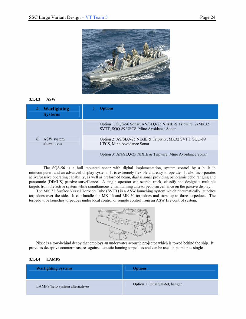
The RHIB or Rigid Hull Inflatable Boats are 7 meters longs, weigh 4400 lbs, have a beam of 9 feet 6 inches and a draft of 13 inches. Using a Cummins 6-cycle, 234 horsepower engine, it can carry up to 18 people.
SSC Large Variant Design – VT Team 5 Page 24
3.1.4.3 ASW
4. Warfighting Systems
5. Options
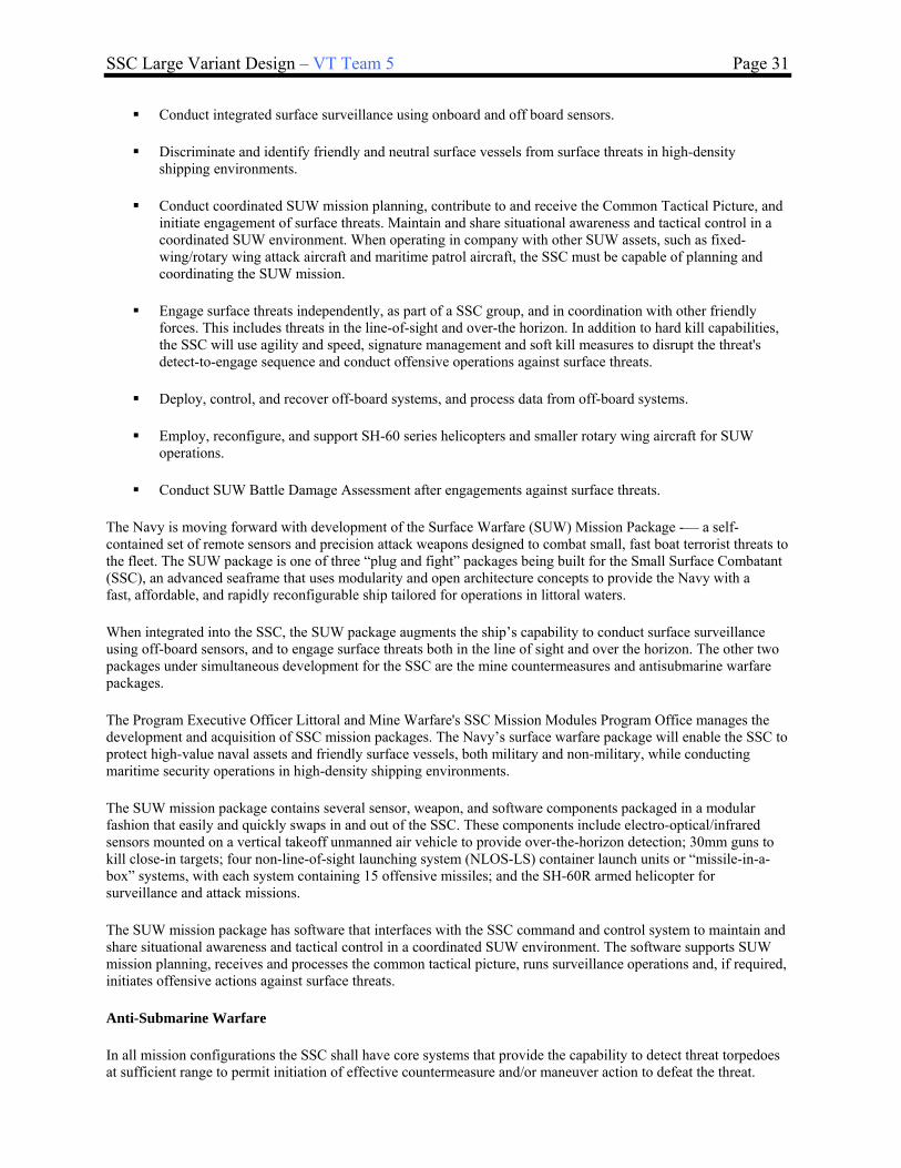
Option 1) SQS-56 Sonar, AN/SLQ-25 NIXIE & Tripwire, 2xMK32 SVTT, SQQ-89 UFCS, Mine Avoidance Sonar
Option 2) AS/SLQ-25 NIXIE & Tripwire, MK32 SVTT, SQQ-89 UFCS, Mine Avoidance Sonar
6. ASW system alternatives
Option 3) AN/SLQ-25 NIXIE & Tripwire, Mine Avoidance Sonar
The SQS-56 is a hull mounted sonar with digital implementation, system control by a built in minicomputer, and an advanced display system. It is extremely flexible and easy to operate. It also incorporates active/passive operating capability, as well as preformed beam, digital sonar providing panoramic echo ranging and panoramic (DIMUS) passive surveillance. A single operator can search, track, classify and designate multiple targets from the active system while simultaneously maintaining anti-torpedo surveillance on the passive display. The MK 32 Surface Vessel Torpedo Tube (SVTT) is a ASW launching system which pneumatically launches torpedoes over the side. It can handle the MK-46 and MK-50 torpedoes and stow up to three torpedoes. The torpedo tube launches torpedoes under local control or remote control from an ASW fire control system.
Nixie is a tow-behind decoy that employs an underwater acoustic projector which is towed behind the ship. It provides deceptive countermeasures against acoustic homing torpedoes and can be used in pairs or as singles.
3.1.4.4 LAMPS
Warfighting Systems Options
LAMPS/helo system alternatives Option 1) Dual SH-60, hangar

SSC Large Variant Design – VT Team 5 Page 25
Option 2) 1 x SH-60, hangar
Option 3) Flight Deck
A SH-60 Seahawk is capable of ASW, search and rescue, ASUW, special operations, cargo lift, and deploying
sonobuoys. It extends the ships radar capabilities. The Seahawk carries either Mk46 or Mk50 torpedoes, two 7.62mm machine guns, and AGM-119 penguin missiles.
Having a flight deck also allows for Vertical Takeoff Unmanned Aircraft Vehicle (VTUAV). It provides an
extension of the ships sensors and is suited for high risk missions. It is small in size and stored easily onboard.
3.1.4.5 GMLS
Warfighting Systems Options
Option 1) 32xMK41 VLS
Option 2) 16xMK48VLS Guided Missile Launcher
Option 3) RAM/SEARAM 11 cell GMLS
The MK 41 VLS is a fixed vertical, multi-canister storage, firing system. It allows fast reaction to multiple threats with concentrated and continuous firepower. Each MK 41 VLS launcher has 16 cells that can be loaded with Tomahawk and Standard Missiles and vertically launched ASROC torpedos. The SEARAM is an evolved close-in weapons system. It is designed to effectively engage future high-performance supersonic threats in the littoral environments. It has an 11 cell launcher and combines Rolling Airframe Missile (RAM) maneuverability, accuracy and extended range with the Phalanx search and track radar and IR systems and quick response capability.

SSC Large Variant Design – VT Team 5 Page 26
3.1.4.6 Combat Systems Payload Summary
In order to trade-off combat system alternatives with other alternatives in the total ship design, combat system characteristics listed in Table 12 are included in the ship synthesis model data base.
Table 12 - Combat System Ship Synthesis Characteristics ROCs Description
AAW 1 Provide anti-air defense AAW 1.1 Provide area anti-air defense AAW 1.2 Support area anti-air defense AAW 1.3 Provide unit anti-air self defense AAW 2 Provide anti-air defense in cooperation with other forces AAW 5 Provide passive and soft kill anti-air defense AAW 6 Detect, identify and track air targets AAW 9 Engage airborne threats using surface-to-air armament
AMW 6 Conduct day and night helicopter, Short/Vertical Take-off and Landing and airborne autonomous vehicle (AAV) operations
AMW 6.3 Conduct all-weather helo ops
AMW 6.4 Serve as a helo hangar
AMW 6.5 Serve as a helo haven
AMW 6.6 Conduct helo air refueling
AMW 12 Provide air control and coordination of air operations
AMW 14 Support/conduct Naval Surface Fire Support (NSFS) against designated targets in support of an amphibious operation
AMW 15 Provide air operations to support amphibious operations
ASU 1 Engage surface threats with anti-surface armaments
ASU 1.1 Engage surface ships at long range
ASU 1.2 Engage surface ships at medium range
ASU 1.3 Engage surface ships at close range (gun)
ASU 1.4 Engage surface ships with large caliber gunfire
ASU 1.5 Engage surface ships with medium caliber gunfire
ASU 1.6 Engage surface ships with minor caliber gunfire
ASU 1.9 Engage surface ships with small arms gunfire
ASU 2 Engage surface ships in cooperation with other forces
ASU 4 Detect and track a surface target
ASU 4.1 Detect and track a surface target with radar
ASU 6 Disengage, evade and avoid surface attack
ASW 1 Engage submarines
ASW 1.1 Engage submarines at long range
ASW 1.2 Engage submarines at medium range
ASW 1.3 Engage submarines at close range
ASW 4 Conduct airborne ASW/recon

SSC Large Variant Design – VT Team 5 Page 27
ROCs Description
ASW 5 Support airborne ASW/recon
ASW 7 Attack submarines with antisubmarine armament
ASW 7.6 Engage submarines with torpedoes
ASW 8 Disengage, evade, avoid and deceive submarines
CCC 1 Provide command and control facilities CCC 1.6 Provide a Helicopter Direction Center (HDC)
CCC 2 Coordinate and control the operations of the task organization or functional force to carry out assigned missions
CCC 3 Provide own unit Command and Control CCC 4 Maintain data link capability CCC 6 Provide communications for own unit CCC 9 Relay communications CCC 21 Perform cooperative engagement FSO 3 Provide support services to other units FSO 5 Conduct towing/search/salvage rescue operations FSO 6 Conduct SAR operations FSO 7 Provide explosive ordnance disposal services FSO 8 Conduct port control functions FSO 9 Provide routine health care FSO 10 Provide first aid assistance FSO 11 Provide triage of casualties/patients FSO 12 Provide medical/surgical treatment for casualties/patients FSO 13 Provide medical, surgical, post-operative and nursing care for casualties/ patients FSO 14 Provide medical regulation, transport/evacuation and receipt of casualties and patients FSO 16 Provide routine and emergency dental care INT 1 Support/conduct intelligence collection INT 2 Provide intelligence INT 3 Conduct surveillance and reconnaissance INT 8 Process surveillance and reconnaissance information INT 9 Disseminate surveillance and reconnaissance information INT 15 Provide intelligence support for non-combatant evacuation operation (NEO) LOG 2 Transfer/receive cargo and personnel LOG 6 Provide airlift of cargo and personnel MIW 3 Conduct mine neutralization/destruction MIW 4 Conduct mine avoidance MIW 6 Conduct magnetic silencing (degaussing, deperming) MIW 6.7 Maintain magnetic signature limits MOB 1 Steam to design capacity in most fuel efficient manner MOB 2 Support/provide aircraft for all-weather operations MOB 3 Prevent and control damage MOB 3.2 Counter and control NBC contaminants and agents MOB 5 Maneuver in formation
MOB 7 Perform seamanship, airmanship and navigation tasks (navigate, anchor, mooring, scuttle, life boat/raft capacity, tow/be-towed)
MOB 10 Replenish at sea MOB 12 Maintain health and well being of crew
MOB 13 Operate and sustain self as a forward deployed unit for an extended period of time during peace and war without shore-based support

SSC Large Variant Design – VT Team 5 Page 28
ROCs Description MOB 16 Operate in day and night environments MOB 17 Operate in heavy weather MOB 18 Operate in full compliance of existing US and international pollution control laws and regulations NCO 3 Provide upkeep and maintenance of own unit NCO 19 Conduct maritime law enforcement operations SEW 2 Conduct sensor and ECM operations SEW 3 Conduct sensor and ECCM operations SEW 5 Conduct coordinated SEW operations with other units STW 3 Support/conduct multiple cruise missile strikes
3.1.5 Modularity Alternatives
In order to explain how modularity is going to be implemented into the ship it is necessary to define modularity and other module type terms that will be used. Module: A module is a structurally independent building block of a larger system with well-defined interfaces. A module is connected to the rest of the system in a manner that allows independent development of the module as long as the interconnections at the interfaces meet the established standards. Modularity: A design approach in which a system component acts as an independently operable unit, subject to periodic change. The system is designed with standardized interfaces, dimensions, and performance parameters for easy assembly and repair or flexible arrangement and use. The concepts of Open Systems and the Modular Open Systems Approach (MOSA) are closely related to modularity. These terms are defined below: Open System – A system that employs modular design and uses consensus-based standards for key interfaces. The system is partitioned into functional elements such that the elements within them represent the technical and functional building blocks of the system. Modular components may be replaced by other modules of similar function and capacity without requiring significant changes to the system. Modular Open Systems Approach (MOSA) – Integrated business and technical strategy that employs a modular design and, where appropriate, defines key interfaces using widely supported, consensus-based standards that are published and maintained by a recognized industry standards organization. There are 3 components that should be considered for designing the modularity options of the vessel. This includes the modules, the interfaces and the platforms the modules will be placed into. The modules themselves can be broken down into a number of different sizes. During the construction stages of the ship modularity can have an impact on how and when certain areas are built. The vessels hull can be broken down into different segments. The traverse structural barriers ranging from the bow of the ship to the stern would be an appropriate place to segment the hull for different packages to be placed in. Also major sub-assemblies with-in these segments can be implemented to speed up the construction process. Foreign ship building yards have now become assembly sites for modules that are built by other companies. A module’s building-block design allows it to be used almost anywhere on the ship. Weapons can be prepackaged into different containers. Radar arrays and masts for radar components can be switched depending on the type of target and proximity of the target to the ship. Habitual places for the crew can have different configurations based on the amount of manning and systems have will have to utilize. Modularity can also be adapted and configured from other ships. The capabilities of the ship can be enhanced through exchange of a module. Most modules that will be used for the vessel are standardized for all ships in the fleet. These pre-built containers can contain anything from off board vehicles to stations containing components for C4I. As long as the interface between the module and the platform is common amongst the modules they can be changed out. It also allows modernization and conversion at the component level. Changing the modules of the system would need to be done because of advancing technology, changes in the threat the vessel faces on its missions and finally modules allows this to easily be done without any major structural changes.
The Small Surface Combatant will take advantage of the newest generation hull form and will have modularity and scalability built in. It focuses on mission capabilities, affordability, and life cycle costs. The SSC is an entirely new breed of U.S. Navy warship. A fast, agile, and networked surface combatant, SSC's modular, focused-mission design will provide Combatant Commanders the required warfighting capabilities and operational flexibility to ensure maritime dominance and access for the joint force. SSC will operate with focused-mission packages that deploy manned and unmanned vehicles to execute missions as assigned by Combatant Commanders. SSC will also perform Special Operations Forces (SOF) support, high-speed transit, Maritime Interdiction Operations (MIO), Intelligence, Surveillance and Reconnaissance (ISR), and Anti-Terrorism/Force Protection

SSC Large Variant Design – VT Team 5 Page 29
(AT/FP). While complementing capabilities of the Navy's larger multi-mission surface combatants, SSC will also be networked to share tactical information with other Navy aircraft, ships, submarines, and joint units.
SSC will transform naval operations in the littorals: The littoral battle space requires focused capabilities in greater numbers to assure access against asymmetrical threats. The SSC is envisioned to be a networked, agile, stealthy surface combatant capable of defeating anti-access and asymmetric threats in the littorals. This relatively small, high-speed combatant will complement the U.S. Navy's Aegis Fleet, DD(X) and CG(X) by operating in environments where it is less desirable to employ larger, multi-mission ships. It will have the capability to deploy independently to overseas littoral regions, remain on station for extended periods of time either with a battle group or through a forward-basing arrangement and will be capable of underway replenishment. It will operate with Carrier Strike Groups, Surface Action Groups, in groups of other similar ships, or independently for diplomatic and presence missions. Additionally, it will have the capability to operate cooperatively with the U.S. Coast Guard and Allies.
SSC will be a Modular Ship. The platform will support mine warfare, anti-submarine warfare and anti-surface boat modules. The SSC concept is presently being defined and is envisioned to be an advanced hullform employing open systems architecture modules to undertake a number of missions and to reconfigure in response to changes in mission, threat, and technology. Primary missions are those that ensure and enhance friendly force access to littoral areas. Access-focused missions include the following primary missions:
Anti-surface warfare (ASuW) against hostile small boats
Mine Counter Measures (MCM)
Littoral Anti-Submarine Warfare (ASW), and may include the following secondary missions
Intelligence, Surveillance and Reconnaissance (ISR)
Homeland Defense / Maritime Intercept
Special Operation Forces support
Logistic support for movement of personnel and supplies.
The mission packages are not included in the basic SSC ship cost, but are paid for separately. The ships were projected in early 2007 to cost between $300 million and $400 million. One of the primary, focused missions of the Small Surface Combatant (SSC) will be littoral ASW. The SSC will be capable of carrying unmanned air, surface and undersea vehicles and other sensors that complement the substantial ASW capabilities planned for DD(X) and the follow on Advanced Cruiser (CG(X)). Revolutionary advances in propulsion, materials, and hull forms are being incorporated into transformational design concepts for the SSC.
SSC is significantly different from other classes of warships in a number of ways. The two most noteworthy are an aggressive spiral development acquisition process that begins deploying and employing SSC while still working out major operational and ship design details, and the design of mission modules that allows each SSC to have the flexibility and adaptability to quickly reconfigure from one warfare specialty to another.
The SSC seaframe without any mission module is a warship with warfare capabilities. It has sensors and weapons, is capable of safe navigation, receives and contributes to the Common Tactical Picture (CTP) and performs limited operational tasking consistent with its capabilities. When a mission module with support personnel is embarked, the now mission focused SSC presents considerably more capabilities than the seaframe, to include defensive capabilities.
The modular Mission Packages are a central feature of the SSC design and will provide the main war fighting capability and functionality for specific mission areas. A Mission Package may consist of a combination of modules, manned and unmanned off-board vehicles, deployable sensors, and mission manning detachments. The modules will be integrated in the ships' module stations or zones. The ship's module stations will have defined volumes, structures, and support service connections. The SSC design must meet the critical performance parameter requirements for mission reconfigurability. The ship's open system architecture will affordably

SSC Large Variant Design – VT Team 5 Page 30
maximize lifecycle flexibility for use of future systems upgrades and required mission systems change-out. This will facilitate the separate production and platform integration of modular mission systems. The major elements of the open systems architecture, module stations, functional element zones, standard interfaces, links, controls etc., will be designed to accommodate future Mission Packages, future ship flights, and technology refresh. Mission packages, to the greatest extent possible, should integrate into the Seaframe's core command and control architecture to minimize the use of unique equipment.
In all mission configurations the SSC shall have core systems that provide the capability to conduct precise navigation to avoid previously identified minefields, and enable the employment of off-board or onboard sensors to perform mine avoidance along the SSC's intended track. When equipped with the appropriate Mission Package, the SSC will conduct mine warfare missions along its intended track and in operational areas as assigned with on-board and off-board systems from deep water through the beach. Mission requirements may dictate employing different package configurations on multiple SSC’s.
Mine & Inshore Warfare [MIW]
The SSC will make use of MIW environmental models and databases. The Mission Package will enable SSC to:
Detect classify and identify surface, moored and bottom mines to permit maneuver or use of selected sea areas.
Coordinate/support mission planning and execution with Joint and Combined assets in the absence of dedicated MIW command and control platforms. MIW mission planning will include the use of organic and remotely operated sensors. The SSC will exchange MIW tactical information including Mine Danger Areas (MDA), mine locations, mine types, environmental data, bottom maps, off-board system locations, planned search areas and confidence factors.
Conduct mine reconnaissance.
Perform bottom mapping.
Perform minefield break through/punch through operations using off-board systems.
Perform minesweeping using off-board mission system.
Conduct precise location and reporting of a full range of MCM contact data. For example: identified mines and non-mine bottom objects.
Perform mine neutralization.
Employ, reconfigure, and support SH-60S for MIW operations.
Embark an EOD detachment.
Deploy, control, and recover off-board systems, and process data from off-board systems.
Surface Warfare
In all mission configurations the SSC shall have core systems that provide the capability to conduct multi-sensor search, detection, classification, localization and tracking of surface contacts in its assigned area of responsibility. The SSC will also have the core capability to protect itself against small boat attacks, including the use of speed and maneuverability, and have the core capability to conduct warning and disabling fire. When equipped with the appropriate Mission Package, the SSC will have the capability to engage surface threats, particularly small fast boats, to minimize threats to friendly units. The Mission Package will enable SSC to:
SSC Large Variant Design – VT Team 5 Page 31
Conduct integrated surface surveillance using onboard and off board sensors.
Discriminate and identify friendly and neutral surface vessels from surface threats in high-density shipping environments.
Conduct coordinated SUW mission planning, contribute to and receive the Common Tactical Picture, and initiate engagement of surface threats. Maintain and share situational awareness and tactical control in a coordinated SUW environment. When operating in company with other SUW assets, such as fixed-wing/rotary wing attack aircraft and maritime patrol aircraft, the SSC must be capable of planning and coordinating the SUW mission.
Engage surface threats independently, as part of a SSC group, and in coordination with other friendly forces. This includes threats in the line-of-sight and over-the horizon. In addition to hard kill capabilities, the SSC will use agility and speed, signature management and soft kill measures to disrupt the threat's detect-to-engage sequence and conduct offensive operations against surface threats.
Deploy, control, and recover off-board systems, and process data from off-board systems.
Employ, reconfigure, and support SH-60 series helicopters and smaller rotary wing aircraft for SUW operations.
Conduct SUW Battle Damage Assessment after engagements against surface threats.
The Navy is moving forward with development of the Surface Warfare (SUW) Mission Package -— a self-contained set of remote sensors and precision attack weapons designed to combat small, fast boat terrorist threats to the fleet. The SUW package is one of three “plug and fight” packages being built for the Small Surface Combatant (SSC), an advanced seaframe that uses modularity and open architecture concepts to provide the Navy with a fast, affordable, and rapidly reconfigurable ship tailored for operations in littoral waters.
When integrated into the SSC, the SUW package augments the ship’s capability to conduct surface surveillance using off-board sensors, and to engage surface threats both in the line of sight and over the horizon. The other two packages under simultaneous development for the SSC are the mine countermeasures and antisubmarine warfare packages.
The Program Executive Officer Littoral and Mine Warfare's SSC Mission Modules Program Office manages the development and acquisition of SSC mission packages. The Navy’s surface warfare package will enable the SSC to protect high-value naval assets and friendly surface vessels, both military and non-military, while conducting maritime security operations in high-density shipping environments.
The SUW mission package contains several sensor, weapon, and software components packaged in a modular fashion that easily and quickly swaps in and out of the SSC. These components include electro-optical/infrared sensors mounted on a vertical takeoff unmanned air vehicle to provide over-the-horizon detection; 30mm guns to kill close-in targets; four non-line-of-sight launching system (NLOS-LS) container launch units or “missile-in-a-box” systems, with each system containing 15 offensive missiles; and the SH-60R armed helicopter for surveillance and attack missions.
The SUW mission package has software that interfaces with the SSC command and control system to maintain and share situational awareness and tactical control in a coordinated SUW environment. The software supports SUW mission planning, receives and processes the common tactical picture, runs surveillance operations and, if required, initiates offensive actions against surface threats.
Anti-Submarine Warfare
In all mission configurations the SSC shall have core systems that provide the capability to detect threat torpedoes at sufficient range to permit initiation of effective countermeasure and/or maneuver action to defeat the threat.

SSC Large Variant Design – VT Team 5 Page 32
When equipped with the appropriate ASW Mission Package, the SSC will conduct multi-sensor ASW detection, classification, localization, tracking and engagement of submarines throughout the water column in the littoral operating environment. The SSC will have the capability to embark ASW/multi-mission helicopters and unmanned vehicles, and will utilize Undersea Surveillance Systems, environmental models and databases. The Mission Package will enable SSC to:
Conduct offensive ASW operations. The SSC must achieve a mission abort or sink a threat submarine, if the submarine target of interest is transiting through a designated key choke point or operating (e.g., patrolling) in a designated search/surveillance area.
Conduct defensive ASW operations. The SSC must defeat threat submarine attacks against units operating in company with CSGs, ESGs, or SSC squadrons. The SSC must achieve a mission abort or sink a threat submarine that poses a threat to any friendly units.
Conduct coordinated ASW, contribute to the Common Undersea Picture, maintain and share situational awareness and tactical control in a coordinated ASW environment.
Maintain the surface picture while conducting ASW in a high-density shipping environment.
Detect, classify, localize, track and attack diesel submarines operating on batteries in a shallow water environment to include submarines resting on the sea floor.
Perform acoustic range prediction and ASW search planning.
Conduct integrated undersea surveillance employing on-board and off-board systems.
Achieve a mission kill of ASW threats through engagement with hard kill weapons from on-board and off-board systems.
Employ signature management and soft kill systems to counter and disrupt the threat's detect-to-engage sequence in the littoral environment.
Deploy, control, recover, and conduct day and night operations with towed and offboard systems, and process data from off-board systems.
Employ, reconfigure, and support SH-60R in ASW operations.
Conduct ASW Battle Damage Assessment after engagements against undersea threats.
Special Operations Forces
The SSC will have an array of inherent capabilities including Joint Littoral Mobility, Intelligence, Surveillance and Reconnaissance, Special Operations Forces support, Maritime Interdiction Operations, Homeland Defense, and Anti-Terrorism/Force Protection.
The SSC' speed, agility, and shallow draft will give it the inherent capability to provide rapid movement of small groups of personnel and material. When equipped with the appropriate Mission Package, the SSC will provide transport and limited lift capability to move personnel, supplies and equipment within the littoral operating environment. The Mission Package will enable SSC to:
Provide facilities for secure stowage of transported materials and equipment.
Provide habitability support for transported personnel.

SSC Large Variant Design – VT Team 5 Page 33
Replenishment and refueling at sea of SH-60 sized non-organic helicopters and SOF craft/boats.
Intelligence, Surveillance and Reconnaissance
In all mission configurations the SSC shall have core systems that provide that level of persistent ISR consistent with the use of installed apertures, automated data collection, storage and processing: emphasizing SSC as an information node for through-put. ISR coverage will include surface, overland and electronic domains, When equipped with the appropriate Mission Package, the SSC will provide enhanced collection and onboard processing capabilities using onboard systems and off-board vehicles and sensors and in some cases embarked detachments that include the capability to conduct Information Operations (TO), Electronic Warfare (EW), Military Deception (MILDEC), Operational Security (OPSEC), Computer Network Defense/Attack (CND/CNA), and Psychological Operations (PSYOP). The SSC will have the command and control architecture and systems to conduct ISR planning and coordination, make near-real-time input to enhance decision making, and facilitate order generation, weapons direction and ship system monitoring and control. The Mission Package will enable SSC to:
Use organic and non-organic resources to conduct surveillance and reconnaissance operations with onboard and off board equipment.
Use organic and non-organic resources to collect, process and disseminate strategic, operational and tactical information.
Use ISR planning, coordination and execution tools.
Naval Special Warfare
The SSC will have the inherent core capability to provide rapid movement of small groups of SOF personnel and material due to the SSC' speed, agility, and shallow draft. When equipped with the appropriate Mission Package, the SSC will have the following SOF capabilities:
Support Naval Special Warfare (NSW) Task Unit and surface/subsurface combatant craft and mobility platforms, or their JSOF equivalent including weapons and equipment stowage, berthing, C4ISR connectivity and space within the hull for mission planning and rehearsal.
Launch, recover, and conduct organic maintenance on multiple embarked and organic craft specified in section 3.1.
Support Marine Expeditionary Unit (Special Operations Capable) [MEU(SOC)] and JSOF hostage rescue operations, aircraft operations for helicopters such as the SH-60S.
Support maritime Special Operations with the capability to refuel MK V Special Operations Craft (SOC) and follow-on (Special Operations Forces) Medium Range Insertion Craft (MRTC).
Support SOF in Noncombatant Evacuation Operations (NEO).
Provide compressed air (diver quality) for the SEAL Delivery Vehicle (SDV).
Embark a Fly Away Recompression Chamber (FARC).
Support and conduct Combat Search and Rescue (CSAR) operations.
Support a Tactical Sensitive Compartmented Information Facility (TSCIF).
Maritime Intercept Operations

SSC Large Variant Design – VT Team 5 Page 34
The SSC will have the inherent core capability to support MIO due to the SSC' speed, agility, and shallow draft, and have the core capability to conduct warning and disabling fire, When equipped with the proper Mission Package, the SSC will have the capability to:
Perform maritime interception and interdiction operations.
Provide staging areas for MIO teams.
Provide a secure holding area for detainees.
Employ, reconfigure, and support SH-60 and smaller rotary wing aircraft for MIO.
Homeland Defense (HLD)
The SSC will have the inherent core capability to support the HLD by providing rapid movement of small groups of personnel and material due to the SSC' speed, agility, and shallow draft. When equipped with the proper Mission Package, the SSC will perform operations to support national and coalition policy. In support of national security and HLD objectives, the ship will be capable of supporting and conducting missions in coordination with the U.S. Coast Guard (USCG). The Mission Package will enable SSC to:
Perform maritime interception, interdiction and law enforcement operations.
Provide staging areas for boarding teams.
Conduct maritime Law Enforcement Operations (LEO) including counter-narcotic operations with embarked law enforcement detachment.
Provide emergency, humanitarian, and disaster assistance.
Support JSOF hostage rescue operations.
Conduct marine environmental protection.
Perform naval diplomatic presence operations.
Employ, reconfigure, and support SH-60 and smaller rotary wing aircraft for HLD, and AT/FP operations.
Antiterrorism/Force Protection (AT/FP)
The SSC will have the inherent core capability to conduct AT/FP through its speed, agility, and shallow draft. When equipped with the proper Mission Package will:
Perform maritime interception, interdiction and law enforcement operations.
Provide staging areas for boarding teams.
Conduct maritime Law Enforcement Operations (LEO) including counter-narcotic operations with embarked law enforcement detachment.
Provide AT/FP to U.S. and friendly forces against attack in port, at anchorage, and during period of restricted maneuvering. Defensive capability will incorporate both passive design and active weapon measures, including non-lethal mechanisms, that can deter, delay, and defend against attack by terrorist and unconventional threats,

SSC Large Variant Design – VT Team 5 Page 35
Employ, reconfigure, and support SH-60 and smaller rotary wing aircraft for HLD, and AT/FP operations.
3.2 Design Space
The Design Variables (DVs) are variables that are changed from design to design in order to find the optimal design for the necessary capabilities for a given mission or mission package. They include the general characteristics of the ship, propulsion systems, manning and sustainability considerations, as well as the necessary war-fighting packages. They are used to develop the Measures of Performance (MOPs) and the Values of Performance (VOPs).
Table 13 - Design Variables (DVs)

SSC Large Variant Design – VT Team 5 Page 36
DV # DV Name Description Design Space
1 LWL Length Waterline 100-140m
2 LtoB Length to Beam ratio 7-10
3 LtoD Length to Depth ratio 11 - 14
4 BtoT Beam to Draft ratio 2.9-3.2
5 Cp Prismatic Coeficient .57-.63
6 Cx Max Section Coef .76-.85
7 Crd Raised Deck Coef .6-.8
8 VD Deckhouse volume 5000-10000m3
9 Cdmat Deckhouse Material 1 = Steel, 2 = Aluminum, 3 = Advanced Composite
Option 1 – mechanical drive, 1 shaft: 2xLM2500+ w/LTDR gear, 2MW SPU (Secondary Propulsion Unit)
Option 2 – mechanical drive, 1 shaft: 2xMT30 w/LTDR gear, 2MW SPU
Option 3 – mechanical drive, 1 shaft: 2xLM2500+ and 1xCAT 3616 w/LTDR gear (CODAG), 2MW SPU
Option 4 – mechanical drive, 2 shafts: 2xLM2500+ w/epicyclic gears
Option 5 – mechanical drive, 2 shafts: 2xMT 30 w/epicyclic gears
Option 6 – mechanical drive, 2 shafts: 2xLM2500+ and 2xCAT 3616 w/LTDR gears (CODAG)
Option 7 – IPS, 2 shafts, 2xPMMs, 4160 VAC, DC ZEDS, 1xLM2500+, 2xCAT 3616 PGMs (Power Generation Modules)
Option 8 – IPS, 2 shafts, 2xPMMs, 4160 VAC, DC ZEDS, 1xMT30, 2xCAT 3616 PGMs
Option 9 – IPS, 2 shafts, 2xPMMs, 4160 VAC, DC ZEDS, 3xLM2500+ PGMs
Option 10 – IPS, 2 shafts, 2xPMMs, 4160 VAC, DC ZEDS, 3xMT30 PGMs
Option 1 - 3xCAT3512B SSDGs (PSYStype=mech drive) or 2xCAT3512B SPGMs (PSYStype=IPS)
Option 2 - 4xCAT3512B SSDGs (PSYStype=mech drive) or 2xCAT3516B SPGMs (PSYStype=IPS)
Option 3 - 3xCAT3516B SSDGs (PSYStype=mech drive) or 2x2MW PEM Fuel Cell SPGMs (PSYStype=IPS)
Option 4 - 4xCAT3516B SSDGs (PSYStype=mech drive) or 2x3MW PEM Fuel Cell SPGMs (PSYStype=IPS)
12 Ts Stores and Provisions 30-60 days
13 CPSCollective Protection System
0 = none, 1 = partial, 2 = full
14 Ndegaus Degaussing system 0 = none, 1 = degaussing system
15 CmanManning reduction and automation factor
0.5 – 0.1
Option 1) AN/SPY-1E MFR - MULTI MODE RADAR, ICMS, AIMS IFF,AIEWS, COMBAT DF, 2xMK137 LCHR SRBOC/NULKA
Option 2) SEAPAR MFR, ICMS, AIMS IFF, AIEWS, COMBAT DF, 2xMK137 LCHR SRBOC/NULKA
Option 3) EADS TRS-3D C-band radar, AIMS IFF, 2xSRBOC, 2xSKWS decoy launcher, WBR 2000 ESM, COMBATSS-21, COMBAT DF
Option 1) MK45 5”/62 gun, AN/SPS-73, IRST, 7m RHIB, 1x30mm CIGS, MK86 GFCS, Small Arms Locker, 2x50cal Machine GunsOption 2) 57mm MK3 naval gun, AN/SPS-73, IRST, 7m RHIB, DORNA EOD EO/IR, Small Arms Locker, 2x50cal Machine GunsOption 3) 57mm MK3 naval gun, AN/SPS-73, FLIR, 7m RHIB, SEASTAR SAFIRE III E/O IR,Small Arms Locker, 2x50cal Machine Guns
Option 1) SQS-56 Sonar, AN/SLQ-25 NIXIE & Tripwire, 2xMK32 SVT T, SQQ-89 UFCS, Mine Avoidance Sonar
Option 2) AS/SLQ-25 NIXIE & T ripwire, MK32 SVT T, SQQ-89 UFCS, Mine Avoidance Sonar
Option 3) AN/SLQ-25 NIXIE & Tripwire, Mine Avoidance Sonar
Option 1) Comm Suite Level A, CTSCE, Cooperative Engagement
Option 2) Comm Suite Level B, CTSCE, Cooperative Engagement
Option 1) 2x Embarked LAMPS w/Hangar
Option 2) 1x Embarked LAMPS w/Hangar
Option 3) LAMPS haven (flight deck)
Option 1) 32xMK41 VLS
Option 2) 16xMK48VLS
Option 3) RAM/SEARAM 11 cell GMLS
Option 1) 1.5xLCS
Option 2) 1xLCS
Option 3) 0.5xLCS
21 GMLS
LAMPS system alternatives
C4ISR system alternatives
Guided Missile Launcher Alternat ives
LAMPS
CCC19
20
11 SSDG/SPGMShip Service Diesel Generator or Secondary Power Generation Module
PSYSPropulsion system alternative
AAW
10
ASW/MCM system alternative
16
17
18
AAW/SEW system Alternative
ASUW system alternativeASUW
ASW
22 MISMODMission Modular Space
and Weight
Option 1) C4I Raft System
Option 2) C4I Track System
Option 3) Conventional Install
Option 1) Mechanical Room Deck Racks
Option 2) HM&E Palletized
Option 3) HM&E Component Modules
Option 4) Conventional Install
Option 1) Habitat Track System
Option 2) Modular Habitat Spaces
Option 3) Conventional Install
Option 1) Maximum Margin and Interface Connectivity
Option 2) Minimum Margin and Interface Connection
Option 3) Same/Similar Weapon-Only Modularity
Option 4) Conventional Install
Option 1) Modular Sensors
Option 2) Modular Mast
Option 3) Conventional Install
23 C4IMODComputer and
Informations Systems Compartment Modularity
24 HMEMODHull and Mechanical Spaces Modularity
25 HABMODHabitat/Living Quarters
Modularity
26 WEAPMOD Weapons Modularity
27 SENSMODSensor Systems
Modularity
SSC Large Variant Design – VT Team 5 Page 37
3.3 Ship Synthesis Model
The primary functions of a synthesis model are to ensure balance and feasibility while providing a means for engineering analysis of the design. By ensuring balance, or a balanced design, we mean to ensure that basic principles are met, such as; displacement equals weight, the design has sufficient space, sufficient volume and has adequate stability. For feasibility we mean to ensure that the cost and risk associated with the design are acceptable. The ability to conduct an engineering analysis on a design is what gives us the ability to determine the cost, risk, stability, volume, etc. and hence the balance and feasibility of the design.
The ship synthesis model for the SSC large is shown in Figure 16. The model in includes both fortran modules and response surface models linked together in the Model Center environment. Response Surface Model (RSM) are parametric (regression) models to inexpensively ``mimic'' the more complex workings of a simulation or experimental data. The RSM’s in this model were developed by running ASSET with Model Center. The RSM’s are then linked to specific modules and take the place of more complex calculations that would normally take place in that module.
The Input module is the first module and it does not conduct calculations but acts as a single point of input for data to the rest of the module. This data can be entered by hand or can take new data from a Multi-Objective Genetic Optimizer, which is linked at the end of the model, to rerun an optimized design.
The Combat Systems and Propulsion modules use data tables developed in ASSET using a baseline design and varying combat system components or machinery components respectively. These modules pull specific systems into the synthesis module where they can be analyzed for balance and feasibility within an optimized ship design.
The Hull module conducts simple naval architecture calculations that are provided to other modules. These calculations include surface area, full load displacement and block coefficient. Linked to the Hull module are RSM’s for hull volume and bare hull structural weight.
The Space Available module calculates the volume of the hull, total ship volume, height and volume of the machinery box, depth at station 10, and the average depth for the ship.
The Electric module calculates power requirements for the ship with the exception of the combat systems power requirements. This module also conducts the ship manning calculation. This module is preceded by RSM’s for effective horsepower, kilowatts, and propulsive coefficient. These RSM’s take the place of what would be a Resistance module.
The Weight module requires the most inputs and provides the most outputs. Some of the inputs this module requires are the payload weights and vertical centers of gravity for the combat systems. Among the outputs are KG, KB, VCG, and GM which are all critical to establishing the design ship’s initial stability. It also calculates the weights of the single digit weight groups and the loads, such as; fuel, water, etc. The Weight module is linked to RSM’s for W320, W330, W4NP, W5, W6 and RSM’s for weights for internal communications (1150), human support (2000), ship support (3000) and auxiliaries (4300).
The Tankage module takes the weight of the fuel from the Weight module and calculates the total tank volume, fuel volume, endurance range, gallons of fuel burned a year, and the average brake horsepower.
The Space Required module compares deck house area available versus area required along with total area available versus area required.
The Feasibility module brings together balance related parameters from previous modules that include space, weight, and performance threshold requirements. The modules outputs are error fractions. These fractions need to be greater than or equal to zero for the ship to be feasible/balanced.
The OMOE and Risk modules calculate the overall measure of effectiveness and risk respectively. The final module before the optimizer is the Cost module. This module calculates the cost of the ship, total life cycle costs, cost of manning and the cost of follow on ships

SSC Large Variant Design – VT Team 5 Page 38
Figure 16 - Ship Synthesis Model in Model Center (MC)
3.4 Objective Attributes
3.4.1 Overall Measure of Effectiveness (OMOE)
The Overall Measure of Effectiveness (OMOE) is a single overall figure of merit index (0-1.0) describing ship effectiveness for specified missions. In order to calculate the OMOE, we take our Measures of Performance (MOPs), which are ship or system performance metrics in required capabilities that are independent of the mission (speed, range, number of missiles), and our Values of Performance (VOP), which are figure of merit indices (0-1.0) specifying the value of a specific MOP to a specific mission area for a specific mission type, and insert these values into the following equation:
Ideally, war-gaming simulations would be used to predict measures of effectiveness for the matrix of ship performance inputs (DOE) in a series of probabilistic scenarios. A regression analysis (RSM) would then be applied to the results in order to define the mathematical relationship between the input ship MOPs and output effectiveness. However, due to constraints, we used expert opinion to integrate these diverse inputs and assess the value or utility of ship MOPs for a given mission, force, and threat. These values are detailed in Tables 5 and 6.
Table 14 - ROC/MOP/DV Summary
ROC Description MOP Related
DV Goal Threshold
MOB 1
Steam to design capacity in most fuel efficient manner MOP 15 - Es LtoB LtoB=10 LtoB=7
MOP 15 - Es LtoD LtoD=17.8 LtoD=10.75 MOP 15 - Es BtoT BtoT=3.2 BtoT=2.8 MOP 15 - Es PSYS PSYS=1 PSYS=6
iii
iii MOPVOPwMOPVOPgOMOE

SSC Large Variant Design – VT Team 5 Page 39
MOB 2
Support/provide aircraft for all-weather operations
MOP 8 - Magnetic LAMPS LAMPS=1 LAMPS=3
MOB 3
Prevent and control damage
MOP 11 - Seakeeping and Stability LtoB LtoB=7 LtoB=10
MOP 11 - Seakeeping and Stability LtoD LtoD=10.75 LtoD=17.8
MOP 11 - Seakeeping and Stability BtoT BtoT=2.8 BtoT=3.2
MOP 10 - RCS VD VD=200,000ft3 VD=140,000ft3 MOP 12 - VUL Cdmat Cdmat=1 Cdmat=2 or 3 MOP 7 - IR PSYS PSYS=1 PSYS=6 MOP 12 - VUL Ndegaus Ndegaus=1 Ndegaus=0 MOP 12 - VUL Cman Cman=0.1 Cman=0.5
MOB 3.2
Counter and control NBC contaminants and agents MOP 9 - NBC CPS Ncps=2 Ncps=0
MOB 5
Maneuver in formation
Required in All Designs
MOB 7
Perform seamanship, airmanship and navigation tasks (navigate, anchor, mooring, scuttle, life boat/raft capacity, tow/be-towed)
Required in All Designs
MOB 12
Maintain health and well being of crew
Required in All Designs
MOB 13 MOP 15 - Es LtoB LtoB=10 LtoB=7 MOP 15 - Es LtoD LtoD=17.8 LtoD=10.75 MOP 15 - Es BtoT BtoT=3.2 BtoT=2.8 MOP 15 - Es PSYS PSYS=1 PSYS=6
Operate and sustain self as a forward deployed unit for an extended period of time during peace and war without shore-based support MOP 14 - Ts Ts Ts=21 days Ts=14 days
MOB 16
Operate in day and night environments
Required in All Designs
MOB 17
Operate in heavy weather
MOP 11 - Seakeeping and Stability LtoB LtoB=7 LtoB=10
MOP 11 - Seakeeping and Stability LtoD LtoD=10.75 LtoD=17.8

SSC Large Variant Design – VT Team 5 Page 40
MOP 11 - Seakeeping and Stability BtoT BtoT=2.8 BtoT=3.2
MOB 18
Operate in full compliance of existing US and international pollution control laws and regulations
Required in All Designs
AAW 1.3
Provide unit anti-air self defense MOP 1 - AAW AAW/SEW AAW/SEW=1 AAW/SEW=4
AAW 2
Provide anti-air defense in cooperation with other forces MOP 1 - AAW AAW/SEW AAW/SEW=1 AAW/SEW=4
MOP 1 - AAW C4ISR C4I=1 C4I=2
AAW 5
Provide passive and soft kill anti-air defense MOP 1 - AAW AAW/SEW AAW/SEW=1 AAW/SEW=4
AAW 6
Detect, identify and track air targets MOP 1 - AAW AAW/SEW AAW/SEW=1 AAW/SEW=4
AAW 9
Engage airborne threats using surface-to-air armament MOP 1 - AAW AAW/SEW AAW/SEW=1 AAW/SEW=4
ASU 1
Engage surface threats with anti-surface armaments MOP 2 - ASUW ASUW ASUW=1 ASUW=3
MOP 2 - ASUW LAMPS LAMPS=1 LAMPS=3
ASU 1.3
Engage surface ships at close range (gun) MOP 2 - ASUW ASUW ASUW=1 ASUW=3
ASU 1.5
Engage surface ships with medium caliber gunfire MOP 2 - ASUW ASUW ASUW=1 ASUW=3
ASU 1.6
Engage surface ships with minor caliber gunfire MOP 2 - ASUW ASUW ASUW=1 ASUW=3
ASU 1.9
Engage surface ships with small arms gunfire MOP 2 - ASUW ASUW ASUW=1 ASUW=3
ASU 2
Engage surface ships in cooperation with other forces MOP 2 - ASUW ASUW ASUW=1 ASUW=3
MOP 4 - C4ISR C4ISR C4ISR=1 C4ISR=2
ASU 4.1
Detect and track a surface target with radar MOP 2 - ASUW ASUW ASUW=1 ASUW=3

SSC Large Variant Design – VT Team 5 Page 41
MOP 2 - ASUW LAMPS LAMPS=1 LAMPS=3
ASU 6
Disengage, evade and avoid surface attack MOP 2 - ASUW ASUW ASUW=1 ASUW=3
ASW 1.3
Engage submarines at close range MOP 3 - ASW LAMPS LAMPS=1 LAMPS=3
ASW 4
Conduct airborne ASW/recon MOP 3 - ASW LAMPS LAMPS=1 LAMPS=3
MOP 3 - ASW ASW/MCM ASW/MCM=1 ASW/MCM=4 MOP 3 - ASW C4ISR C4ISR=1 C4ISR=2
ASW 5
Support airborne ASW/recon MOP 3 - ASW LAMPS LAMPS=1 LAMPS=3
MOP 3 - ASW C4ISR C4ISR=1 C4ISR=2
ASW 8
Disengage, evade, avoid and deceive submarines MOP 13 - Vs LtoB LtoB=10 LtoB=7
MOP 13 - Vs LtoD LtoD=17.8 LtoD=10.75 MOP 13 - Vs BtoT BtoT=3.2 BtoT=2.8 MOP 13 - Vs PSYS PSYS=1 PSYS=6 MOP 3 - ASW ASW/MCM ASW/MCM=1 ASW/MCM=4 MIW 4
Conduct mine avoidance MOP 3 - ASW ASW/MCM ASW/MCM=1 ASW/MCM=4
MIW 6.7
Maintain magnetic signature limits MOP 12 - VUL Cdmat Cdmat=2 or 3 Cdmat=1
MOP 12 - VUL Ndegaus Ndegaus=1 Ndegaus=0
CCC 1
Provide command and control facilities MOP 4 - C4ISR C4ISR C4ISR=1 C4ISR=2
CCC 3
Provide own unit Command and Control MOP 4 - C4ISR C4ISR C4ISR=1 C4ISR=2
CCC 4
Maintain data link capability MOP 4 - C4ISR C4ISR C4ISR=1 C4ISR=2
CCC 6
Provide communications for own unit MOP 4 - C4ISR C4ISR C4ISR=1 C4ISR=2
CCC 9
Relay communications MOP 4 - C4ISR C4ISR C4ISR=1 C4ISR=2
CCC 21
Perform cooperative engagement MOP 4 - C4ISR C4ISR C4ISR=1 C4ISR=2
SEW 2
Conduct sensor and ECM operations MOP 1 - AAW AAW/SEW AAW/SEW=1 AAW/SEW=4
SEW 3
Conduct sensor and ECCM operations MOP 1 - AAW AAW/SEW AAW/SEW=1 AAW/SEW=4
FSO 6
Conduct SAR operations
MOP 5 - FSO/NCO LAMPS LAMPS=1 LAMPS=3
FSO 8
Conduct port control functions
MOP 5 - FSO/NCO C4ISR C4ISR=1 C4ISR=2

SSC Large Variant Design – VT Team 5 Page 42
MOP 13 - Vs LtoB LtoB=10 LtoB=7 MOP 13 - Vs LtoD LtoD=17.8 LtoD=10.75 MOP 13 - Vs BtoT BtoT=3.2 BtoT=2.8 MOP 13 - Vs PSYS PSYS=1 PSYS=6 MOP 2 - ASUW ASUW ASUW=1 ASUW=3
MOP 5 - FSO/NCO LAMPS LAMPS=1 LAMPS=1
INT 1
Support/conduct intelligence collection MOP 6 - MCM LAMPS LAMPS=1 LAMPS=3
MOP 6 - MCM C4ISR C4ISR=1 C4ISR=2 INT 2
Provide intelligence MOP 6 - MCM LAMPS LAMPS=1 LAMPS=3
MOP 6 - MCM C4ISR C4ISR=1 C4ISR=2
INT 3
Conduct surveillance and reconnaissance MOP 6 - MCM LAMPS LAMPS=1 LAMPS=3
MOP 6 - MCM C4ISR C4ISR=1 C4ISR=2
LOG 1
Conduct underway replenishment
Required in All Designs
LOG 2
Transfer/receive cargo and personnel (CONREP)
Required in All Designs
LOG 6
Provide airlift of cargo and personnel (VERTREP)
MOP 8 - Magnetic LAMPS LAMPS=1 LAMPS=3
NCO 3
Provide upkeep and maintenance of own unit
Required in All Designs
NCO 19
Conduct maritime law enforcement operations MOP 2 - ASUW ASUW ASUW=1 ASUW=3
MOP 13 - Vs LtoB LtoB=10 LtoB=7 MOP 13 - Vs LtoD LtoD=17.8 LtoD=10.75 MOP 13 - Vs BtoT BtoT=3.2 BtoT=2.8 MOP 13 - Vs PSYS PSYS=1 PSYS=6
Table 15 - MOP Table MOP# MOP Goal Threshold Related DV
AAW/SEW=1 AAW/SEW=3 AAW/SEW option 1 AAW C4I=1 C4I=2 C4I option
ASUW=1 ASUW=1 ASUW option Mod SUW=1 Mod SUW=5 Mod SUW option LAMPS=1 LAMPS=2 LAMPS option
2 ASUW/NSFS
C4I=1 C4I=2 C4I option
ASW/MCM=1 ASW/MCM=2 ASW/MCM option 3 ASW/MCM Mod MIW/MCM=1 Mod
MIW/MCM=6 Mod MIW/MCM option

SSC Large Variant Design – VT Team 5 Page 43
Mod ASW=1 Mod ASW=4 Mod ASW option LAMPS=1 LAMPS=2 LAMPS option C4I=1 C4I=2 C4I option
4 C4ISR C4I=1 C4I=2 C4I option
5 MISMOD LAMPS=1 LAMPS=2 LAMPS option
LAMPS=1 LAMPS=2 LAMPS option 6 MCM C4I=1 C4I=2 C4I option
7 IR SPGM=1 SPGM=0 SPGM Option
8 Magnetic Ndegaus=1 Ndegaus = 0 Degaussing Option
9 NBC Ncps=2 Ncps=0 CPS option
10 RCS VD=4000 VD=8000 Deckhouse volume, m3
11 Seakeeping and Stability LtoB=8 LtoB=6.5 LtoB LtoD=12 LtoD=8.5 LtoD BtoD=3.4 BtoD=3 BtoD
12 VUL (Vulnerability) Cdmat=1 Cdmat=3 Ship material
13 Vs (Sprint Speed) 50 40 knots
14 Ts (Provisions) 28 14 days
15 Es (Endurance range at 18 kt) 6000 3000 nm 16 Draft 3 5 m 17 Acoustic signature PSYS=3,4 PSYS=1,2,5,6 PSYS Option
OMOE Hierarchy
OMOE
AAW
Damage
Detection
Vs
Es
Survivability
Mobility
Weapons ASUW
ASW
195 DP210 DP225 DP
+5 m2
‐5 m2
baseline
35
30
4500
3500
AN/SPY‐1E MFR ‐MULTI MODE RADAR, ICMS, AIMS IFF,AIEWS, COMBAT DF, 2xMK137 LCHR SRBOC/NULKA
SEAPAR MFR, ICMS, AIMS IFF, AIEWS, COMBAT DF, 2xMK137 LCHR SRBOC/NULKA
EADS TRS‐3D C‐band radar, AIMS IFF, 2xSRBOC, 2xSKWS decoy launcher, WBR 2000 ESM, COMBATSS‐21, COMBAT DF
SQS‐56 Sonar, AN/SLQ‐25 NIXIE & Tripwire, 2xMK32 SVTT, SQQ‐89 UFCS, Mine Avoidance Sonar
AS/SLQ‐25 NIXIE & Tripwire, MK32 SVTT, SQQ‐89 UFCS, Mine Avoidance Sonar
AN/SLQ‐25 NIXIE & Tripwire, Mine Avoidance Sonar

SSC Large Variant Design – VT Team 5 Page 44
Figure 17 - OMOE Hierarchy
iii
iii MOPVOPwMOPVOPgOMOE
Figure 18 - AHP Pairwise Comparison
Figure 19 – Bar Chart Showing MOP Weights
0
0.1
0.2
0.3
0.4
0.5
0.6
0.7
0.8
0.9
1
40 41 42 43 44 45 46 47 48 49 50
VS (knots)
VOP13(VS)
Figure 20 - Value of Performance Function for Sprint (Sustained) Speed

SSC Large Variant Design – VT Team 5 Page 45
3.4.2 Overall Measure of Risk (OMOR)
The purpose of OMOR is to calculate a quantitative overall measure of risk (OMOR) for a specific design based on the selection of technologies defined in the design variable table. The three types of risk we measured were performance, cost and consequence. We identified risk events associated with specific design variables, required capabilities, schedule and cost. A Pi and Ci were estimated for each risk event using
Table 17 and
Table 18 to define the metric for each variable. Pi is the probability of occurrence of a major impact on performance, cost or schedule. Ci is the consequence of occurrence of a major impact on performance, cost or schedule. The product of Pi and Ci is the calculated risk for that specific event. After the risk is calculated for each event it is recorded in a risk register shown in Table 16. The calculated risk associated with each type of risk is summed and multiplied by a weight given to the risk of performance, cost and schedule all designated by W in the OMOR equation below. We used pair-wise comparison to calculate OMOR hierarchy weights.
kkk
kschedjjj
jtiii
ii
iperf CPwWCPwWCP
w
wWOMOR
cos
Table 16 - Risk Register
SW BS Risk TypeRelated
DV #DV
OptionsDV Description Risk Event Ei Event # Pi Ci Ri
1 Performance DV6 2,3 Hull Material implementation problems 1 0.5 0.7 0.35
1 Cost DV6 2,3 Hull MaterialLack of industrial base for working with non-steel materials
2 0.3 0.3 0.09
2 Performance DV7 7,8,9,10Integrated power system
Development and use of new IPS system
3 0.4 0.4 0.16
2 Cost DV7 7,8,9,10Integrated power system
Development and use of new IPS system will incur cost
4 0.3 0.6 0.18
2 Schedule DV7 7,8,9,10Integrated power system
Development and use of new IPS system will be behind schedule
5 0.3 0.3 0.09
4 Performance DV12 0.5-1.0Manning & automation factor
Development and integration of automation systems
6 0.3 0.7 0.21
4 Cost DV12 0.5-1.0Manning & automation factor
Development and integration of automation systems will have cost overruns
7 0.4 0.4 0.16
4 Schedule DV12 0.5-1.0Manning & automation factor
Development and acquisition cost overruns will be behind schedule
8 0.4 0.4 0.16
4 Performance DV13 1 SPY-1E MFRDoes not meet performance TLRs
9 0.4 0.5 0.2
4 Schedule DV13 1 SPY-1E MFRSchedule delays impact program
10 0.3 0.35 0.105
4 Cost DV13 1 SPY-1E MFRDevelopment and acquisition cost overruns
11 0.3 0.65 0.195
4 Performance DV13 2 SEAPAR MFRDoes not meet performance TLRs
12 0.4 0.5 0.2
4 Schedule DV13 2 SEAPAR MFRSchedule delays impact program
13 0.3 0.35 0.105
4 Cost DV13 2 SEAPAR MFRDevelopment and acquisition cost overruns
14 0.3 0.65 0.195
4 Performance DV13 3 EADS TRS-3D C-band radar
Does not meet performance TLRs
15 0.4 0.5 0.2
4 Schedule DV13 3 EADS TRS-3D C-band radar
Schedule delays impact program
16 0.3 0.35 0.105
4 Cost DV13 3 EADS TRS-3D C-band radar
Development and acquisition cost overruns
17 0.3 0.65 0.195

SSC Large Variant Design – VT Team 5 Page 46
Table 17 - Event Probability Estimate Probability What is the Likelihood the Risk Event Will Occur?
0.1 Remote 0.3 Unlikely 0.5 Likely 0.7 Highly likely 0.9 Near Certain
Table 18 - Event Consequence Estimate Given the Risk is Realized, What Is the Magnitude of the Impact? Consequence
Level Performance Schedule Cost 0.1 Minimal or no impact Minimal or no impact Minimal or no impact
0.3 Acceptable with some reduction in margin
Additional resources required; able to meet need dates
<5%
0.5 Acceptable with significant reduction in margin
Minor slip in key milestones; not able to meet need date
5-7%
0.7 Acceptable; no remaining margin
Major slip in key milestone or critical path impacted
7-10%
0.9 Unacceptable Can’t achieve key team or
major program milestone >10%
3.4.3 Cost
There are many things to consider in the cost of a ship. The life cycle cost of a ship is significantly different from the acquisition cost because it also includes the ownership of the ship over its useful life span. The life cycle cost of the ship includes but is not limited to development, acquisition, operations, support, logistics, and disposal costs. A parametric method is used in calculating cost. It is a statistical method using “like” elements to relate weight and other parameters to cost. In a cost model the following inputs are used: power and propulsion system, deck house material, speed and endurance range, fuel volume, SWBS weight groups 100-700, number of personnel, profit margin, inflation rate, number of ships to be built, and base year for cost calculations. Using the inflation factor the cost for each SWBS group 100-700 is calculated. The weight of each group is multiplied by complexity factors. This total is then multiplied by margin weight and added to SWBS 800,900 costs to end up with a lead ship basic construction cost. Adding change order costs, government costs, and delivery costs produces a final acquisition cost for the lead ship. The quality of the cost estimate is important but usually a class D estimate of within 20% is adequate. Building more ships is cost effective because the lead ship is more expensive due to design costs. It also requires more effort from the shipyard because each time they build a new ship they “learn” how to put it together. When building multiple ships the shipyard will learn to build each ship more efficiently. A learning factor helps estimate the cost of the follow ships. Cost of Lead ship

SSC Large Variant Design – VT Team 5 Page 47
Figure 21 - Naval Ship Acquisition Cost Components
Learning Factor
Figure 22 - Naval Ship Acquisition Cost Components
3.5 Multi-Objective Optimization
3.6 Optimization Results and Initial Baseline Design (Variant 137)
The non-dominated frontier presented in Figure 10 show the relationship between cost, effectiveness, and risk. Figures 10 and 11 show that the most effective designs are some of the cheapest; however, those designs are high risk. For the purposes of this design, high risk designs are more likely to be looked at. It is interesting to note that as cost increases, the overall effectiveness and risk decreases. The designs that will be used in this report will be those that fall in the range of high risk, high effectiveness, and low cost.

SSC Large Variant Design – VT Team 5 Page 48
Figure 23 – 3D Non-Dominated Frontier
Figure 24 – 2D Non-Dominated Frontier
SSC Large Variant Design – VT Team 5 Page 49
3.7 Improved Baseline Design – Single Objective Optimization
Design 137 was chosen to be further optimized using Model Center’s gradient optimizer tool. This tool allows the fine tuning of continuous design variables in order to maximize or minimize a certain characteristic, usually cost, or OMOE. In our single objective optimization, cost was chosen two be minimized, while putting constraints on other variables in order to keep them within required values. This optimization allows the best design from the 3 dimensional design spaced to be further optimized for cost. The design variable output results from Design 137 were only allowed to be varied in a very small range about their value from Design 137.
The results of the single objective optimization are shown in Table 16 and compared to the Design 137 values.

SSC Large Variant Design – VT Team 5 Page 50
Table 19 - Design Variables Summary Design
Variable Description Trade-off Range Initial Baseline
(Variant 137) Improved Baseline
LWL Length Waterline 115 -130 128.5 121.8 L to B Length to Beam ratio 7.5 – 8.1 8.4 8 L to D Length to Depth ratio 13 – 13.5 13.26 13.02 B to T Beam to Draft ratio 2.9 – 3 2.93 3 Cp Prismatic Coefficient .6 - .63 .61 .621 Cx Midship section Coefficient .79 - .85 .79 .831 Crd .7 - .8 .73 .8 VD Volume Displacement 5000 – 7500 5561 5522 Cman Manning Factor .5 - .7 .5088 .7
Table 20 – Improved Baseline Weights and Vertical Center of Gravity Summary Group Weight VCG
SWBS 100 1484.64 5.94 SWBS 200 748.59 3.24 SWBS 300 311.79 7.31 SWBS 400 149.28 7.90 SWBS 500 768.97 7.51 SWBS 600 395.12 3.89 SWBS 700 107.87 6.07 Lightship 4362.88 5.71 Lightship w/Margin 4680 6.19 Full Load w/Margin 5204.45 5.76
Table 21 – Improved Baseline Area Summary Area Required Available
Total-Arrangeable 4727 4699 Deck House 2301 3088
Table 22 – Improved Baseline Electric Power Summary
Group Description Power SWBS 200 Propulsion SWBS 300 Electric Plant, Lighting SWBS 430, 475 Miscellaneous SWBS 521 Firemain SWBS 540 Fuel Handling SWBS 530, 550 Miscellaneous Auxiliary SWBS 561 Steering SWBS 600 Services CPS CPS KWNP Non-Payload Functional Load KWMFLM Max. Functional Load w/Margins KW24 24 Hour Electrical Load

SSC Large Variant Design – VT Team 5 Page 51
Table 20 – Improved Baseline / ASSET Design Principal Characteristics Characteristic SSSM ASSET FFG
Displ, Full Load 5204 5481 4453
L 121.8 121.8 124.4
B 15.1 15.1 13.7
T 5.03 5.3 5.1
D10 9.35 9.3 9.1
KG 5.2 5.8 5.7
KB 2.95 3.19 3.16
Vol Total 17535 20139 15028
Vol Deckhs 5521 8536 4350
Prop 2 2 1
Total Power Reqd 55000 NA NA
Total Power Inst 70199 70199 36064
SS Generators 4 x CAT3516B 4 x CAT3516B 4xDD 16v149TI
SS Power Total 10000 10000 4000
Sustained Speed 31.7 30.1 27.5
Endurance Speed 20 20 20
Range at Endr 4621 3560 3469.2
Provisions 70 70 NA
Fuel Capacity 497.8 497.8 557
Officers 19 19 13
Enlisted 46 46 180
Total Crew (Berthing Allowance) 65 (90) 65 (90) 193
Lead ship acquisition cost $912.60 NA NA
Follow ship acq cost $658.55 NA NA
Follow ship total owner cost $1.31 NA NA
Sustained Speed (knts) 31.7 30.1 27.5
Endurance Range (nm) 4621 3560 3469
Total Required Area 4727 3835 2801
Total Available Area 4699 2194 2332
Available Hull Volume 12899 11602 10678
Maximum Functional Load with Margins 3567 4313.3 3385
Average 24 Hour Electric Load 1629 1893 1373
Full Load Displacement 5204 5481 4453
Usable Fuel Weight 498 498 557
KG 5.19 5.8 5.7
GM 0.133 0.085 0.071
SWBS 100 1484.64 1695 1551.9
SWBS 200 748.59 840.8 307.2
SWBS 300 311.79 366.8 245.1
SWBS 400 149.28 168 143.5
SWBS 500 768.97 607.3 523.4
SWBS 600 395.12 376 349.1
SWBS 700 107.87 111.9 99
Wm24 396.62 428.3 389.5
Lightship 4362.88 4594.2 3608.7
SWBS F10 8.88 9.1 21.8
SWBS F31 11.66 16.5 28.7
SWBS F32 3.71 3.2 14.9
SWBS F41 497.78 524 586.3
SWBS F46 17.88 29.2 14.5
SWBS F52 9.9 12.4 32.3
Variable Payload 287.89 NA 402.9
Full Load 5204.45 5481.1 4453.9
Power System2x LM2500-21
CODAG 2xLM2500+ 2xCAT3616
CODAG 2xLM2500+ 2xCAT3616

SSC Large Variant Design – VT Team 5 Page 52
3.8 ASSET Feasibility Study
The improved baseline is the model that will be developed into a full ship design in the Concept Development stage. The improved baseline design variable values were entered into ASSET for the purposes of a feasibility study of the Synthesis Model (SSSM) method. The improved baseline and the ASSET model using the improved baseline variables are listed in Table 20.
The SSSM and ASSET models compare favorably in most categories. There are some discrepancies in the individual SWBS weight groups and a large difference in the endurance range. While these differences require some investigation, the relatively close results of the two models should validate the method of the MOGO optimization of ship design during the concept exploration stage. The ASSET model based on the improved baseline will be used during several design steps during Concept Development. Specifically it will be used to assist with preliminary arrangements and weight calculations. Below in Figure 25 is the ASSET machinery arrangements output that will be used to assist in machinery placement during concept development.
In Table 20 the improved baseline and the improved ASSET model are compared to the Navy’s legacy FFG7. This comparison is made due to the relative size and capabilities the improved baseline resulted in. Designing the SSC to the lower sustained speed of between 30 – 35 knots has resulted in a larger vessel with more area defense capabilities than if the SSC were designed to the higher speed threshold. Because the improved baseline in significant missile, radar, and sonar technologies, the SSC will be able to contribute to area AAW and ASW defense of a CSG/ESG. These capabilities along with its size and speed would mean the SSC would be able to fill the role of the FFG in the CSG/ESG while still being able to meet the littoral defense requirements of the SSC.
1.0 0.9 0.8 0.7 0.6 0.5 0.4 0.3 0.2 0.1 0.0
AP FP
0 10 20 30 MSCALE
ASSET/MONOSC V5.3.0 - MACHINERY MODULE - 1/26/2010 22:36. 0DATABANK-TEAM5ASSET2009RSMBASELINES.BNK SHIP-SSCLG
GRAPHIC DISPLAY NO. 1 - SHIP MACHINERY LAYOUT
Figure 25 - ASSET Improved Baseline Machinery Arrangements

SSC Large Variant Design – VT Team 5 Page 53
4 Concept Development (Feasibility Study)
Concept Development of SSC large follows the design spiral in sequence after Concept Exploration. In Concept Development the general concepts for the hull, systems and arrangements are developed. These general concepts are refined into specific systems and subsystems that meet the ORD requirements. Design risk is reduced by this analysis and parametrics used in Concept Exploration are validated.
4.1 Hull Form and Deck House
4.1.1 Hullform
Hullform development was the first phase of the concept development process. A 3D model of the hullform and deckhouse were created in Rhino based on the principal characteristics of the improved baseline. An iges file from the ASSET improved baseline hull was imported into Rhino where curves were lofted, and faired hull surfaces were created. At this stage, an AN/SQS-56 sonar dome was added to the hullform.
During the hullform development phase, emphasis was placed on minimizing drag, providing good maneuvering and seakeeping characteristics, and maximizing developable surfaces to reduce acquisition costs. The faired hull lines and a table of principal particulars is presented in Figure 26.
Error! Objects cannot be created from editing field codes.
Figure 26: SSC Large Lines Drawing
Once the hullform had been finalized in Rhino, preliminary hydrostatics were created using ORCA 3D. The intact heeling arm curve for the vessel at varying drafts is presented in Figure 27. Curves of form for vessel are presented in Figure 27 through Figure 32.
Figure 27: Intact Righting Arm Curves

SSC Large Variant Design – VT Team 5 Page 54
Figure 28: Buoyancy Centers
Figure 29: Wetted Area and Waterplane Area

SSC Large Variant Design – VT Team 5 Page 55
Figure 30: Displacement, TPC Immersion, and Moment to Trim Curves
Figure 31: Hullform Coefficients

SSC Large Variant Design – VT Team 5 Page 56
Figure 32: Sectional Area Curves
4.1.2 Deck House
The deckhouse was shaped and positioned in Rhino to support mission systems, provide an efficient means for routing the intakes and exhausts, and to provide volume and surface area to support weapons sensors, the AN/SPY 1E X Band arrays, and the other combat system antennas. The position of the deckhouse was also modified from the improved ASSET baseline in order to align the deckhouse transverse subdivision with the hull transverse subdivision. The Rhino 3D model of the hull and deckhouse are shown in Figure 33
Figure 33: Refined Hullform and Deckhouse

SSC Large Variant Design – VT Team 5 Page 57
4.2 Preliminary Arrangement (Cartoon)
The cartoon of the large SSC is created as part of concept development in order to ensure that the vessel has the required area and volume, and to ensure that all large objects fit into the hull. The preliminary arrangement defines the primary hull and deckhouse subdivision by placing decks and bulkheads in order to locate tanks, large machinery spaces, and other large object spaces. In establishing a preliminary general arrangement, static and damaged stability, trim, machinery arrangements and propulsion train alignment, signatures, large object arrangement, engine intakes and uptake routing, structural efficiency, survivability, producibility, and mission requirements must be considered. Preliminary arrangements will guide more detailed general arrangements later on in concept development. The preliminary arrangement was created by using the hull and deckhouse profile and deck plan views from the Rhino model and the required area and volume reports from the ASSET improved baseline model to establish the hull subdivision. The Rhino model with the hullform and deckhouse built from the improved ASSET improved baseline ship synthesis model is shown below in Figure 34.
Figure 34: Rhino Hullform and Deckhouse Model
The required area and volumes and manning profile used to establish the preliminary hull subdivision is given in Table 23.
Table 23: Required Areas and Volumes

SSC Large Variant Design – VT Team 5 Page 58
VD 5221.89 m3
deckhouse volume
Vtk 929.2 m3
total tankage volume
Vaux 834.153 m3
auxillary machinery space volume
Vht 12012.6 m3
total hull volume
Vmb 1853 m3
propulsion machinery box volume
ADPR 971.82 m2
required deckhouse payload area
AHPR 682.418 m2
required hull or deckhouse payload area
Ahie 147 m2
required hull propulsion inlet and exhause area
Adie 510 m2
required deckhouse propulsion inlet and exhaust area
Ts 70 endurance days
Cn 5.6638 hull cubic number
NT 65 total crew
NO 19 number of officers
NA 16 number of additional accomodations
Adr 2350 m2
total deckhouse required area
Ada 3088 m2
available deckhouse area
Atr 4727 m2
total required arrangeable area
Ata 4699.7 m2
total available arrangeable area
REQUIRED AREAS AND VOLUMES
These required areas and volumes from the improved baseline model were used to place transverse watertight bulkheads and decks, and create an initial topsides arrangement. The cartoon for the large SSC is shown below in Figure 35. This cartoon shows the location of transverse bulkheads, decks and platforms, machinery spaces, engine intakes and exhausts, large object spaces, and mission module spaces. This cartoon also shows an initial tankage arrangement to meet the required tankage volumes and meet intact and damaged stability requirements.
Figure 35: Large SSC Preliminary Arrangement (Cartoon)

SSC Large Variant Design – VT Team 5 Page 59
The following cartoon shows an initial topside arrangement large SSC with placement of the improved baseline X band arrays and hull features to meet the required mission profile.
Figure 36: Mission Profile Features
4.3 Design for Production
In the concept and requirements exploration phase, design for production is one of the major inputs into the cost model. The decisions that are made at an early stage in concept design and preliminary design will have a large impact upon the cost and schedule of the ship.
A generic build strategy was first established for the large SSC. The generic build strategy includes producibility features as described below:
1). Design a producible hull form with modular construction techniques (avoid complex curvature of panels) 2). Create a zonal classification as shown with the following numbering scheme
– Bow/stern - 1000/3000- more curvature and transition to transverse stiffening – Machinery - 2000- difficult distributed systems and outfitting – Deckhouse – 4000 – reduced curvature and lighter zones – On-board - 5000 - actually defines construction stage - electrical wiring, etc. – Special - 6000 - high skill - electronics, CS, accommodations
3). Follow the unit break criteria outlined below to allow for improved handling and erection of units – Above deck (10cm) and aft of TBHD (25cm) – Stiffeners on FWD side of TBHD (except in Machinery spaces) – Blocks extend between TBHD - attempt to keep TBHD spacing less than plate length
(50’) – Max unit width - 10m – Units one deck high except wing tanks/spaces and in bow – Max structural assembly weight of 200 MT
4). Use the following guidelines when creating the general arrangements – Air locks on fwd side of TBHD – Standard openings / closures – Escape trunks on fwd side of TBHD – Standard space arrangements, avoid mirror image (Troop Living, Crew Living, etc) – Use modular living quarters where possible – Transverse passageways on aft side of TBHD – Locate habitability spaces away from machinery spaces and intake/uptakes to avoid
acoustic insulation 5). Use a zonal distribution for electrical, HVAC, and the firemain for zonal outfitting 6). Use service tunnels to minimize bends in piping and cable 7). Use the following techniques in detailed design to minimize unnecessary production costs
– Permit wire brushing in lieu of blasting of erection butts and seams

SSC Large Variant Design – VT Team 5 Page 60
– Permit one-sided welding with ceramic backing tape when joining units – Use sleeve couplings to join piping – Use pre-fab plate with piping welded to it for bulkhead penetrations. – Maximize retention of CFE and GFE paint – Permit use of weld-through primer – Minimize use of HY and HSLA materials to reduce pre-heating requirements. – Use standard shapes/plates. Avoid using built up sections (require more welding and
straightening than rolled shaped – Minimize complex curvature in plates above the waterline
If these guidelines in the generic build strategy are followed throughout preliminary and detailed
design, significant cost and time savings will be seen in the shipyard. Given the cost cap of $400 million for follow ship acquisition, it is essential that these guidelines be followed.
Refinements were made to the ASSET improved baseline design for producibility. Unnecessary deck shear was eliminated from the forward and aft ends of the ship. This eliminated curvature from the decks in these regions of the ship, and will allow for the deck panels to be effectively built in the panel line without heating and rolling the plates and stiffeners. This change is shown in Figure 37.
Figure 37: Producibility Improvements – Shear Removed
Another producibility improvement that was made to the large SSC from the improved baseline was that the locations of the transverse bulkheads in the deckhouse were shifted al align with the transverse bulkheads in the hull. This will help to improve the structural efficiency of the design. The deckhouse was also shortened because the volume contained in the deckhouse of the improved baseline was greater than required. The structural continuity improvement is detailed in Figure 38.

SSC Large Variant Design – VT Team 5 Page 61
Figure 38: Producibility Improvements - Structural Continuity
The ship service diesel generator in AMR 2 was also relocated to MMR 2 in order to avoid complex routing of the intakes and uptakes through the deckhouse. The improved baseline design placed the second ship service diesel generator below the flight deck. This would have been problematic because the intakes and uptakes would have to have been routed away from the flight deck, and through the deckhouse. Relocating the generator to a main machinery space below the deckhouse provides an improved intake and uptake arrangement. This improvement to the improved baseline design is shown in Figure 39.
Figure 39: Producibility Improvements – Machinery Arrangement
Hull sections from the improved baseline design were also examined from a producibility point of view. The objective was to re-shape the hull above the design waterline where possible to straighten the sections. This helped to reduce complex curvature and avoid having to heat and roll the shell and shell stiffeners in the shipyard. The body plan of the large SSC from the ASSET improved baseline is shown in Figure 40.

SSC Large Variant Design – VT Team 5 Page 62
BL
DWL
Figure 40: Improved Baseline Sections
These sections had relatively minor curvature above the design waterline to begin with, but the hullform was refined and the sections were straightened. The Gaussian curvature for the refined hull form was examined in Rhino and is shown in Figure 41. The Gaussian curvature is a measure of complex curvature, and is a helpful visual aid to show whether the surfaces can be developed from a flat panel. A smooth surface has two principal curvatures. The Gaussian curvature is a product of the principal curvatures. The SSC hullform Gaussian Curvature close to zero almost everywhere.
Figure 41: Refined Hullform Gaussian Curvature
The guidelines listed in the generic build strategy are to be followed regardless of which shipyards are
selected for lead and follow ship acquisition. These are strategies that will be built into the design that will help to lower cost and increase shipbuilding efficiency. The choice of shipbuilder also impacts the

SSC Large Variant Design – VT Team 5 Page 63
acquisition cost and schedule for the large SSC, but early in the concept and preliminary design, the lead and follow yards have typically not been selected.
The major US shipyards specializing in the construction of naval surface combatants have improved their efficiency in the past decade. This is due to improvements and advancements in the shipbuilding methodology. These shipyards are moving away from “stick building” ships on a set of inclined building ways, and are moving towards building progressively larger units under cover. Shipyards like Bath Iron Works have built large assembly buildings to move the ship construction under cover to the greatest extend possible. Ship structural units are stacked vertically into a grand block, and multiple grand blocks are then joined together into an ultra unit under the cover of climate controlled buildings. The structural units that make up the large SSC are presented in Figure 42 through Figure 45.
1110
1120
1210
1220
1230
1240
1310
1320
1330
1340
1410
1420
1430
1440
1510
1520
1530
1540
1610
1620
1630
1640
Figure 42: 1000 Grand Block Units
2110
2120
2130
2140
2210
2220
2230
2240
2310
2320
2330
2340
Figure 43: 2000 Grand Block Units
3110
3120
3130
3140
3210
3220
3230
3240
3310
3320
3330
3410
3420
3430
Figure 44: 3000 Grand Block Units
4110
4120
4130
4140
4210
4220
4230
4240
4310
4320
4330
4340
Figure 45: 4000 Grand Block Units

SSC Large Variant Design – VT Team 5 Page 64
These structural units are then stacked vertically in an assembly building prior to blast and paint to form grand blocks. The grand blocks for the ship are given in Figure 46 through Figure 49.
1100
12001300140015001600
Figure 46: 1000 Grand Blocks
210022002300
Figure 47: 2000 Grand Blocks
3100320033003400
Figure 48: 3000 Grand Blocks
410042004300
Figure 49: 4000 Grand Blocks
In addition to moving much of the ship construction process out of the elements, much of the ships outfitting is also brought under cover. Ultra units similar the one shown in Figure 50 are currently being constructed in specialized assembly buildings. These units can be several thousand tons, and have a high degree of zonal outfitting accomplished prior to erection with other ultra units on the land level transfer facility (LLTF). The 4 ultra units that will form the hull and deckhouse of the large SSC are shown in Figure 51.

SSC Large Variant Design – VT Team 5 Page 65
Figure 50: Modern Ultra Unit
Ultra 3000 Ultra 2000 Ultra 1000
Ultra 4000
Figure 51: Large SSC Ultra Units
In order to establish a preliminary schedule of principal events for the construction of the large SSC, a claw chart was established to show the unit erection schedule for a modern shipyard like Bath Iron Works. This claw chart was built with the assumption that serial production of multiple large SSC would be underway at any given time. It is important to establish a unit erection schedule and schedule of principal events for a ship being built in modern shipyard, because numerous ships are under construction simultaneously, and the ship construction schedule as defined in the build contract must be closely adhered to. The claw chart presented in Figure 52 shows how the individual units will be stacked vertically to create grand blocks. The grand blocks will then be joined with other grand blocks to form ultra units. The entire ship will be constructed in 4 ultra units that will be completed under cover, and moved to the Land Level Transfer Facility (LLTF) for erection with other ultra units.
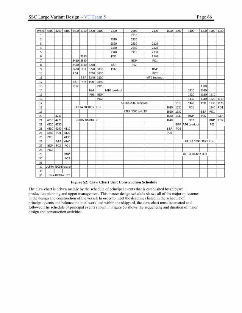
SSC Large Variant Design – VT Team 5 Page 66
Week 4300 4200 4100 3400 3300 3200 3100 2300 2200 2100 1600 1500 1400 1300 1200 1100
1 2210
2 2310 2220
3 2320 2230 2110
4 2330 2240 2120
5 2340 PO1 2130
6 3310 PO1 2140
7 3410 3320 B&P PO1
8 3420 3330 3210 B&P P02
9 3430 PO1 3220 3110 PO2 B&P
10 PO1 3230 3120 PO2
11 B&P 3240 3130 MTG Loadout
12 B&P PO2 PO1 3140
13 PO2 PO1 1310
14 B&P MTG Loadout 1410 1320
15 P02 B&P 1420 1330 1210
16 PO2 1430 1340 1220 1110
17 1510 1440 PO1 1230 1120
18 1610 1520 PO1 1240 PO1
19 1620 1530 B&P PO1
20 4210 1630 1540 B&P PO2 B&P
21 4310 4220 1640 PO2 B&P PO2
22 4320 4230 B&P ATG Loadout P02
23 4330 4240 4110 B&P PO2
24 4340 PO1 4120 PO2
25 PO1 4130
26 B&P 4140
27 B&P P02 PO1
28 PO2
29 B&P
30 PO2
31
32
33
34
ULTRA 1000 to LLTF
ULTRA 3000 Erection
ULTRA 4000 Erection
ULTRA 1000 ERECTION
ULTRA 2000 Erection
ULTRA 3000 to LLTF
ULTRA 2000 to LLTF
Ultra 4000 to LLTF
Figure 52: Claw Chart Unit Construction Schedule
The claw chart is driven mainly by the schedule of principal events that is established by shipyard production planning and upper management. This master design schedule shows all of the major milestones in the design and construction of the vessel. In order to meet the deadlines listed in the schedule of principal events and balance the total workload within the shipyard, the claw chart must be created and followed.The schedule of principal events shown in Figure 53 shows the sequencing and duration of major design and construction activities.

SSC Large Variant Design – VT Team 5 Page 67
Event DescriptionDuration
(months)MBD
1 Contract Award 0 66
2 Detail Design 36 64
3 Material Procurement 45 60
4 MFG/Production Planning 64 64
5 2D Drawing Extraction 20 57
6 Material Lofting 20 57
7 Start Fab 39 48
8 Start Compartment Testing 38 44
9 Start Pre‐Outfit (1st Unit) 24 44
10 Grand Block Erection 18 40
11 Ultra Unit Erection and Outfit 20 32
12Combat/AEGIS Weapon Systems
Loadout17 30
13 Lay Keel 0 24
14Ultra Unit Assembly (distributed
systems integration)6 24
15 Complete Hull Assembly 0 18
16 Electrical Cable Pull 12 18
17 Distributed Systems Testing 13 17
18 Prop Shaft Loadout/Alignment 3 18
19 Light Off SSGTGs 0 13
20 Aegis Combat System Light Off 9 13
21 Ship Translation/Launch 0 12
22 Compartment Inspections (GI's) 8 9
23 Complete Compartment Testing 0 6
24 Main Engine Light Offf 0 6
25 Start Dock Trials 0 5
26 Start Builders Trials 2 5
27 Start Acceptance Trials 0 3
28 Delivery 0 0
Figure 53: Schedule of Principal Events
4.4 Subdivision
The primary subdivision and tankage arrangement was established in order to define large object spaces with sufficient maintenance envelopes and arrangeable space and volume, establish a tankage arrangement, and ensure that the vessel meets the intact and damaged stability criteria given in the US Navy DDS 079. After an initial primary subdivision was defined to meet tankage and large object space requirements, a floodable length curve was generated in HECSALV to ensure that the ship can survive damage along at lease 15% of the DWL.
4.4.1 Hullform in HECSALV
The rhino hull file was imported into HECSALV using the ship project editor. The general process used to define the primary subdivision in HECSALV is given below:

SSC Large Variant Design – VT Team 5 Page 68
Rhino was used initially to generate a hullform from the ASSET improved baseline offsets, and that hullform was modified to include a number of producibility improvements. The Rhino hullform is shown in Figure 54.
Figure 54: Improved Rhino Hullform
These sections were imported into HECSALV, and the sections were faired and cleaned up where required. Once the Rhino hull file was input into HECSALV, the hull principal particulars were input into HECSALV from the improved baseline. The hullform in HECSALV with the hull form parameters defined is shown in Figure 55.
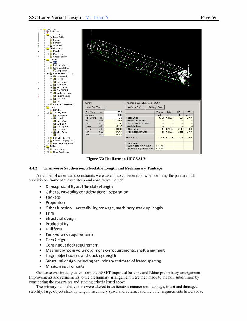
SSC Large Variant Design – VT Team 5 Page 69
Figure 55: Hullform in HECSALV
4.4.2 Transverse Subdivision, Floodable Length and Preliminary Tankage
A number of criteria and constraints were taken into consideration when defining the primary hull subdivision. Some of these criteria and constraints include:
Guidance was initially taken from the ASSET improved baseline and Rhino preliminary arrangement.
Improvements and refinements to the preliminary arrangement were then made to the hull subdivision by considering the constraints and guiding criteria listed above.
The primary hull subdivisions were altered in an iterative manner until tankage, intact and damaged stability, large object stack up length, machinery space and volume, and the other requirements listed above

SSC Large Variant Design – VT Team 5 Page 70
were met. The finalized locations of decks and transverse watertight bulkheads are shown below in Figure 56 and Figure 57.
Figure 56: Deck Locations
Figure 57: Transverse Bulkhead Locations
The profile and plan views of the primary hull subdivision with the decks and bulkheads and bulkheads modeled are shown in Figure 58. In these views, orange spaces are unassigned spaces (available for berthing, operations, mission spaces, etc), lube oil tanks are purple, potable water tanks are light blue, seawater ballast tanks are dark blue, fuel oil tanks are red, JP-5 tanks are black, machinery spaces are light green, mission spaces are dark green, and oily waste tanks are maroon.

SSC Large Variant Design – VT Team 5 Page 71
Figure 58: Hull Primary Subdivision
A summary of the volumes and centers for the fuel groups, machinery spaces, mission spaces, and other spaces as calculated by HECSALV is given in Figure 59.
Figure 59: HECSALV Tankage Summary
4.4.3 Loading Conditions and Preliminary Stability Analysis
Loading conditions were defined in HECSALV for the lightship, full load, and minimum operating conditions. The lightship condition was first defined, and then the other loading conditions were defined. The lightship condition was taken from the ASSET improved baseline with design development. This condition is a theoretical condition that would be approached as the ship went into a dry-docking period. It does not contain any liquid loads, or expendable loads such as munitions, personnel and their effects, or stores. The preliminary lightship weight for the large SSC is 4166 MT, and the preliminary lightship VCG is 5.65 m ABL. The lightship loading condition and upright hydrostatics are shown in Figure 60.
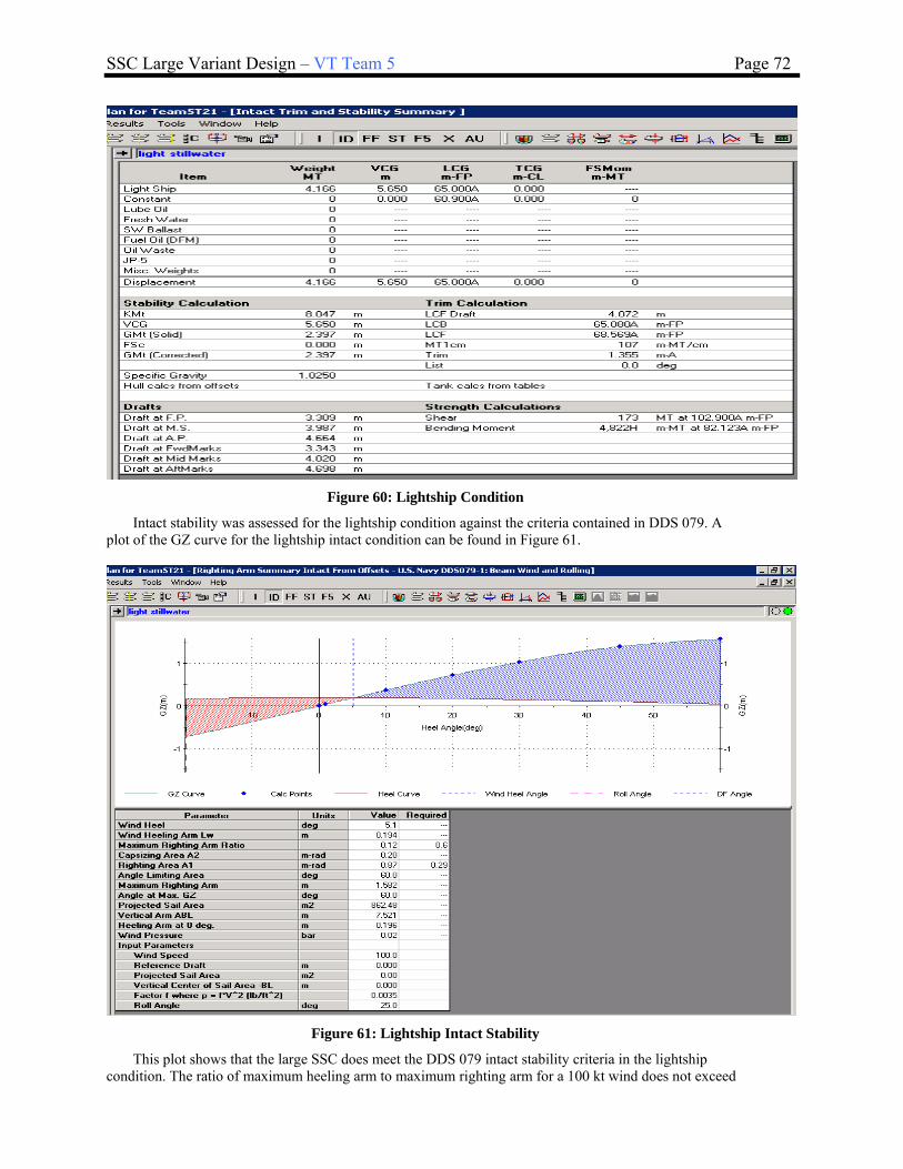
SSC Large Variant Design – VT Team 5 Page 72
Figure 60: Lightship Condition
Intact stability was assessed for the lightship condition against the criteria contained in DDS 079. A plot of the GZ curve for the lightship intact condition can be found in Figure 61.
Figure 61: Lightship Intact Stability
This plot shows that the large SSC does meet the DDS 079 intact stability criteria in the lightship condition. The ratio of maximum heeling arm to maximum righting arm for a 100 kt wind does not exceed
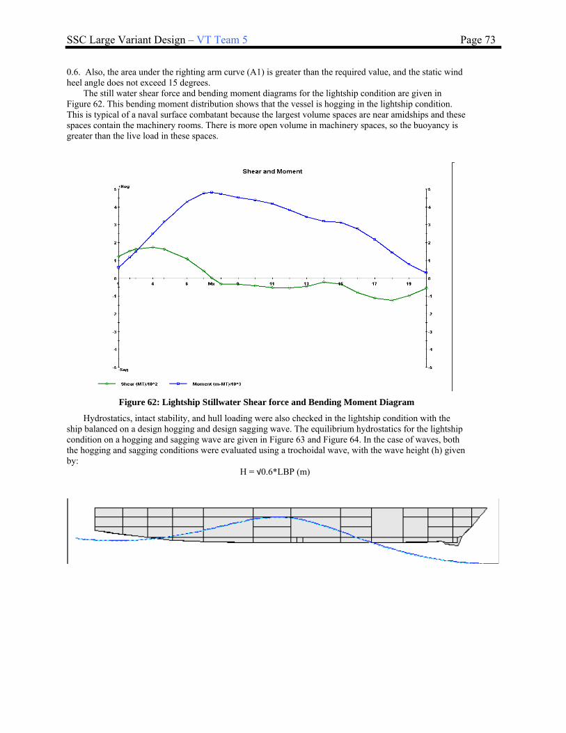
SSC Large Variant Design – VT Team 5 Page 73
0.6. Also, the area under the righting arm curve (A1) is greater than the required value, and the static wind heel angle does not exceed 15 degrees.
The still water shear force and bending moment diagrams for the lightship condition are given in Figure 62. This bending moment distribution shows that the vessel is hogging in the lightship condition. This is typical of a naval surface combatant because the largest volume spaces are near amidships and these spaces contain the machinery rooms. There is more open volume in machinery spaces, so the buoyancy is greater than the live load in these spaces.
Figure 62: Lightship Stillwater Shear force and Bending Moment Diagram
Hydrostatics, intact stability, and hull loading were also checked in the lightship condition with the ship balanced on a design hogging and design sagging wave. The equilibrium hydrostatics for the lightship condition on a hogging and sagging wave are given in Figure 63 and Figure 64. In the case of waves, both the hogging and sagging conditions were evaluated using a trochoidal wave, with the wave height (h) given by:
H = √0.6*LBP (m)

SSC Large Variant Design – VT Team 5 Page 74
Figure 63: Lighship Hogging Wave Equilibrium Condition
Figure 64: Lighship Sagging Wave Equilibrium Condition
The shear force and bending moment diagram for the hogging and sagging conditions were calculated for lightship and are shown in Figure 65 and Figure 66.

SSC Large Variant Design – VT Team 5 Page 75
Figure 65: Lightship Hogging Design Wave Shear force and Bending Moment Diagram
Figure 66: Lightship Sagging Design Wave Shear force and Bending Moment Diagram
The minimum operating condition was taken from the the ASSET improved baseline with design development. This condition is a theoretical condition that would be approached as the ship went into a dry-docking period. It reduces the fuel oil, lube oil, fresh water, and stores to 1/3 of the full load values. The preliminary minimum operating condition displacement for the large SSC is 4443 MT, and the preliminary VCG is 5.337. The lightship loading condition and upright hydrostatics are shown in Figure 67.

SSC Large Variant Design – VT Team 5 Page 76
Figure 67: Minimum Operating Condition
Intact stability was assessed for the min op condition against the criteria contained in DDS 079. A plot of the GZ curve for the intact condition is shown in Figure 68.
Figure 68: MinOp Intact Stability
This plot shows that the large SSC does meet the DDS 079intact stability criteria in the MinOp condition. The ratio of maximum heeling arm to maximum righting arm for a 100 kt wind does not exceed
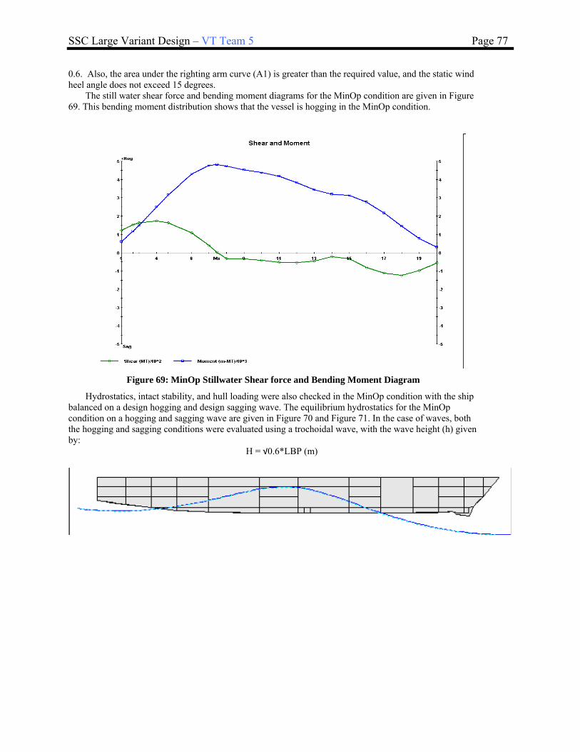
SSC Large Variant Design – VT Team 5 Page 77
0.6. Also, the area under the righting arm curve (A1) is greater than the required value, and the static wind heel angle does not exceed 15 degrees.
The still water shear force and bending moment diagrams for the MinOp condition are given in Figure 69. This bending moment distribution shows that the vessel is hogging in the MinOp condition.
Figure 69: MinOp Stillwater Shear force and Bending Moment Diagram
Hydrostatics, intact stability, and hull loading were also checked in the MinOp condition with the ship balanced on a design hogging and design sagging wave. The equilibrium hydrostatics for the MinOp condition on a hogging and sagging wave are given in Figure 70 and Figure 71. In the case of waves, both the hogging and sagging conditions were evaluated using a trochoidal wave, with the wave height (h) given by:
H = √0.6*LBP (m)

SSC Large Variant Design – VT Team 5 Page 78
Figure 70: MinOp Hogging Wave Equilibrium Condition
Figure 71: MinOp Sagging Wave Equilibrium Condition
The shear force and bending moment diagram for the hogging and sagging conditions were calculated for MinOp and are shown in Figure 72.

SSC Large Variant Design – VT Team 5 Page 79
Figure 72: MinOp Hogging Design Wave Shear force and Bending Moment Diagram
Figure 73: MinOp Sagging Design Wave Shear force and Bending Moment Diagram
The Full Load condition was taken from the ASSET improved baseline with design development. In this condition, the lube oil, fuel oil, potable water and stores all at their maximum service load. The

SSC Large Variant Design – VT Team 5 Page 80
preliminary Full Load displacement for the large SSC is 5224 MT, and the preliminary lightship VCG is 4.601 m ABL. The full load loading condition and upright hydrostatics are shown in Figure 74.
Figure 74: Full Load Stillwater Condition
Intact stability was assessed for the full load condition against the criteria contained in DDS 079. A plot of the GZ curve for the intact condition is shown in Figure 75.
Figure 75: Full Load Intact Stability
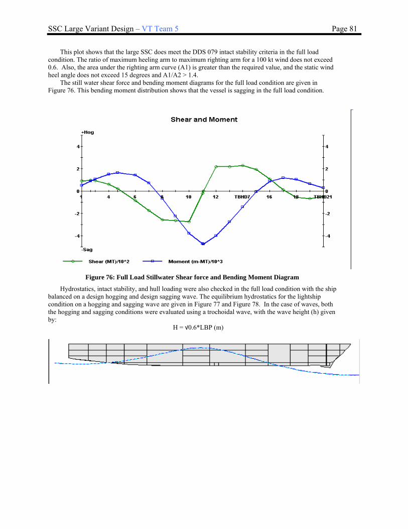
SSC Large Variant Design – VT Team 5 Page 81
This plot shows that the large SSC does meet the DDS 079 intact stability criteria in the full load condition. The ratio of maximum heeling arm to maximum righting arm for a 100 kt wind does not exceed 0.6. Also, the area under the righting arm curve (A1) is greater than the required value, and the static wind heel angle does not exceed 15 degrees and A1/A2 > 1.4.
The still water shear force and bending moment diagrams for the full load condition are given in Figure 76. This bending moment distribution shows that the vessel is sagging in the full load condition.
Figure 76: Full Load Stillwater Shear force and Bending Moment Diagram
Hydrostatics, intact stability, and hull loading were also checked in the full load condition with the ship balanced on a design hogging and design sagging wave. The equilibrium hydrostatics for the lightship condition on a hogging and sagging wave are given in Figure 77 and Figure 78. In the case of waves, both the hogging and sagging conditions were evaluated using a trochoidal wave, with the wave height (h) given by:
H = √0.6*LBP (m)

SSC Large Variant Design – VT Team 5 Page 82
Figure 77: Full Load Hogging Wave Equilibrium Condition
Figure 78: Full Load Sagging Wave Equilibrium Condition

SSC Large Variant Design – VT Team 5 Page 83
The shear force and bending moment diagram for the hogging and sagging conditions were calculated for full load and are shown in Figure 79and Figure 80.
Figure 79: Full Load Hogging Design Wave Shear force and Bending Moment Diagram
Figure 80: Full Load Sagging Design Wave Shear force and Bending Moment Diagram

SSC Large Variant Design – VT Team 5 Page 84
4.5 Structural Design and Analysis
A full structural model of the SSC was created in MAESTRO in order to fully simulate the loading on the ship using US Navy structural load criteria. Structural inputs were taken from ASSET in order to determine the main scantlings and the 3D Rhino model was used to input the faired geometry of the SSC.
4.5.1 Geometry, Components and Materials
The geometry of the structural model was initially created by using buttock lines and waterlines to create the endpoints in MAESTRO. The lines were output from the 3D Rhino model and provided the geometry of the outer hull at each station. The Buttock heights are provided in Table 24, and the Waterline half-breadths are provided in Table 25.
Table 24: Buttock Heights from the 3D Rhino Model
BUTTOCK HEIGHTS
Buttock Buttock Buttock ButtockFP Station 0.000 2.000 4.000 6.000 Station
1 0.900 9.436 0.900 1.000
2 6.900 3.425 8.544 6.900 2.000
3 14.900 ‐0.460 4.460 8.191 10.789 14.900 3.000
4 22.900 0.007 1.270 4.924 8.554 22.900 4.000
5 32.900 0.002 0.568 1.776 5.447 32.900 5.000
6 42.900 0.000 0.373 1.070 2.661 42.900 6.000
7 58.900 0.000 0.100 0.491 1.661 58.900 7.000
8 70.900 0.000 0.105 0.481 1.511 70.900 8.000
9 86.900 0.043 0.437 1.182 2.489 86.900 9.000
10 98.900 0.673 1.235 2.111 3.388 98.900 10.000
11 110.900 2.049 2.551 3.225 4.384 110.900 11.000
AP 121.800 3.560 3.865 4.383 6.475 121.800 aft
Table 25: Waterline Half-Breadths from the 3D Rhino Model
Waterline Waterline Waterline Waterline WaterlineStation 1.500 5.000 5.300 8.000 11.000 Station
FP 0.900 -1.361 0.9001 6.900 -0.465 -0.536 -1.675 -3.811 6.9002 10.809 -0.362 -1.276 -1.384 -2.776 -5.075 10.8093 14.900 -0.900 -2.221 -2.353 -3.871 -6.182 14.9004 22.900 -2.201 -4.036 -4.181 -5.657 -7.663 22.9005 32.900 -3.674 -5.820 -5.941 -7.078 -7.663 32.9006 42.900 -4.791 -6.890 -6.973 -7.731 -7.663 42.9007 58.900 -5.833 -7.485 -7.543 -8.032 -7.663 58.9008 70.900 -5.988 -7.531 -7.589 -8.060 -7.663 70.9009 86.900 -4.619 -7.493 -7.566 -8.055 -7.663 86.900
10 98.900 -2.684 -7.273 -7.386 -7.933 -7.663 98.90011 110.900 -6.490 -6.644 -7.398 -7.663 110.900AP 121.800 -5.179 -5.418 -6.452 -7.010 121.800
WATERLINE HALF-BREADTHS
The remaining geometrical inputs were taken from the output of the ASSET hull structures module. ASSET produced the frame spacing for the model, which was set as a standard 2.0 m, as well as the location of the design waterline, the deck locations, and the transition points for changes in material
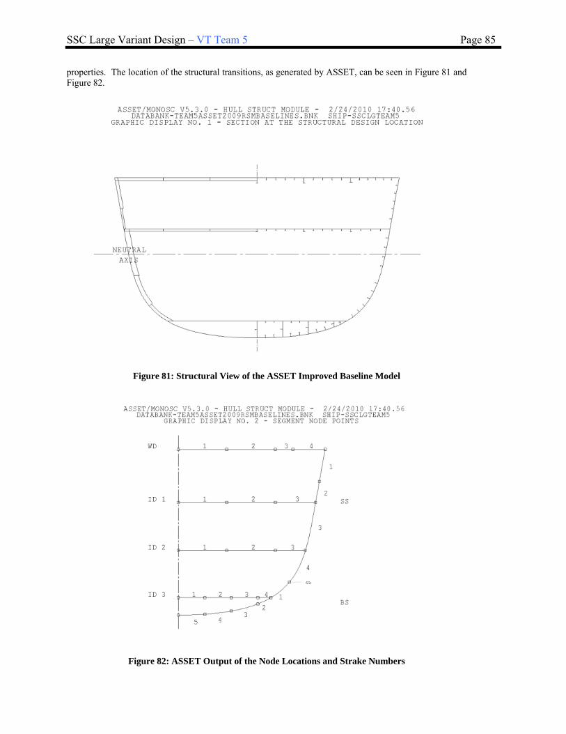
SSC Large Variant Design – VT Team 5 Page 85
properties. The location of the structural transitions, as generated by ASSET, can be seen in Figure 81 and Figure 82.
Figure 81: Structural View of the ASSET Improved Baseline Model
Figure 82: ASSET Output of the Node Locations and Strake Numbers

SSC Large Variant Design – VT Team 5 Page 86
Using all of the geometric inputs, the next step in the process of building the structural model in MAESTRO is entering the endpoints for each compartment of the ship. This particular ship has 11 compartments, each separated by a transverse bulkhead. The compartments are first modeled as a wireframe of endpoints one compartment at a time, as seen in Figure 83. MAESTRO considers each compartment a separate MAESTRO module, and each module is built independently. MAESTRO also allows for port/starboard symmetry when creating the model, so only half of the ship is required to be built.
Figure 83: MAESTRO Screenshot showing the Endpoints for Compartment 9
Once the geometry is outlined, the materials and the structural scantlings are input from ASSET. HSS was used for the plating throughout the ship in its initial design and HY-80 was used for the frames, stiffeners, girders, and beams. This design choice would be reconsidered in the second round of the design spiral, due to the low stresses seen in the analysis of the structural model. HSS could be used for the structural members in order to lower cost and construction time, and HY-80 could be used at strategic locations where the additional strength could prove beneficial. The crack arrestor strake and bilge strake are typical areas where naval surface combatants have HY-80 structural members and plating.
ASSET provided all of the scantling geometry provided for the bottom shell, side shell, weather deck, the internal decks, the transverse bulkheads, the girders, the frames, and the stiffeners. The structural scantlings are shown in the amidships line drawing, shown in Figure 84.
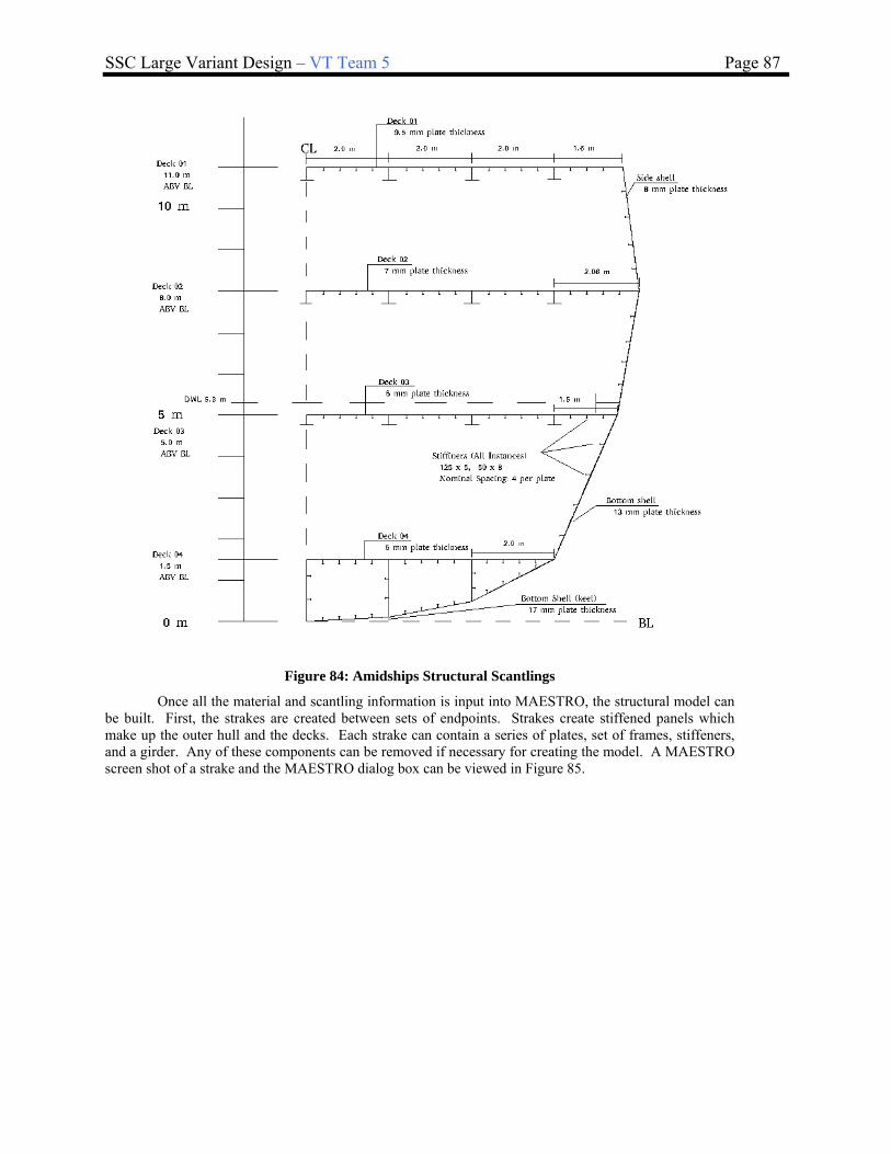
SSC Large Variant Design – VT Team 5 Page 87
Figure 84: Amidships Structural Scantlings
Once all the material and scantling information is input into MAESTRO, the structural model can be built. First, the strakes are created between sets of endpoints. Strakes create stiffened panels which make up the outer hull and the decks. Each strake can contain a series of plates, set of frames, stiffeners, and a girder. Any of these components can be removed if necessary for creating the model. A MAESTRO screen shot of a strake and the MAESTRO dialog box can be viewed in Figure 85.

SSC Large Variant Design – VT Team 5 Page 88
Figure 85: MAESTRO Strakes
Once the outer hull plate and the decks have been created, the other finite elements can be added
in order to create transverse bulkheads, and beam supports. MAESTRO supports seven types of finite elements; however this model only used quads and triangle elements to create the transverse bulkheads and rods to create stanchions, which add structural support in the absence of a deck. Figure 86 shows a MAESTRO screen shot where the quads and triangle elements which were used to create a transverse bulkhead.
Figure 86: MAESTRO Quad and Tri Finite Elements Creating a Transverse Bulkhead

SSC Large Variant Design – VT Team 5 Page 89
Once the transverse bulkheads have been created for each compartment, compound finite elements are used to create tanks in the inner bottom. Compounds are simply a series of repeated finite elements, such as quads or triangle elements that can be created across an entire module. In this model, the compounds will be used for the inner structure of the tanks, as seen in Figure 87. Once the tanks are created, the boundary of the tank, which will be made up of strakes, finite elements, and compounds is defined in MAESTRO. Designating this boundary is accomplished by creating a volume group in MAESTRO. This group entity allows the user to select the boundary of the tank and isolate this structure from surrounding structure. In the case of this model, these volume groups will be used to load the tanks with liquids which will accurately model the load conditions of the liquid inside the tank.
Figure 87: MAESTRO Tank Boundaries
Once the model is built and the groups are defined, a thorough check of the model must be performed in order to ensure the final structural calculations will be reliable. These checks include working through the endpoints to ensure everything remains in alignment, looking for free edges where finite elements are not properly connected, looking for duplicate elements, checking the pressure/non-pressure side of the plating, checking the side which the stiffeners are mounted on the stiffened panel, and even checking the aspect ratio, warp, and the internal angle of finite elements. A myriad of problems can be introduced into the structural model during its construction, and these checks are an integral part of creating a viable structural model. Once the final structural model passes its integrity checks, it can it be loaded and tested. The final structural model for the SSC can be seen in Figure 88, and an amidships section view can be seen in Figure 89.

SSC Large Variant Design – VT Team 5 Page 90
Figure 88: MAESTRO Full Ship Structural Model
Figure 89: Amidships Section View of the MAESTRO Structural Model

SSC Large Variant Design – VT Team 5 Page 91
4.5.2 Loads
The structural model required two primary loads that are assigned to the structural modules. These loads will be consistent for all of the loading conditions that test the adequacy of the structural model. These loads are the tank loads and the lightship loads associated with the weight of each module. The loads are separated into these two categories in order to allow MAESTRO to account for the differences in analysis of the liquid loads within the tanks versus the structural load and the permanent weight of the outfitting of the ship. Table 26 shows the necessary volume of tankage as required by the HECSALV model against the calculated volume available in the tanks that were modeled in the structural model; and Figure 90 shows a sample tank in MAESTRO along with its loading dialog box. As seen in this figure, the volume of the tank can be filled with the desired density of liquid, i.e. 840 kg/m3 for JP5 and DFM, as well as to the desired tank level. This model assumes the tanks are filled to 98% capacity.
Table 26: Comparison Between MAESTRO and HECSALV Tankage Volumes
From HECSALV From MAESTRO1/2 Ship Capacity Volume Group Name Volume (m 3̂) Weight (kg) Weight (MT)
Name Volume Density Weight tank - mod2 3 2795 3m3 MT/m3 MT tank - mod3 29 24266 24
Lube Oil 15 0.92 13 tank - mod4 82 67128 67Fresh Water 4 1.00 4 tank - mod5 75 62067 62SW Ballast 28 1.01 28 tank - mod6 84 69220 69
Fuel Oil (DFM) 287 0.84 241 tank - mod7 37 30760 31Oil Waste 14 0.92 13 tank - mod8 24 19854 20
JP-5 23 0.84 19 tank - mod9 10 10088 10
Total 370 318 Summary 345 286178 286
Figure 90: MAESTRO Sample Tank
Following the loading of the tanks, the lightship weight of each module is provided to MAESTRO. This allows the appropriate weight distribution to be simulated in the structural model for each compartment. Having an accurate weight distribution of each module is critical for the structural simulations. Careful calculation of the equipment and outfitting of each compartment will ensure the structure accurately responds to the loads that are placed upon it. The first round of preliminary design does not always allow for an accurate calculation of the weight distribution, so adjustments are made to match the sum of the module weights to the full load displacement, as seen in Table 27. The final ship weight distribution can be seen in Figure 91.
Table 27: Weight of MAESTRO Modules with Modifications for Full Load
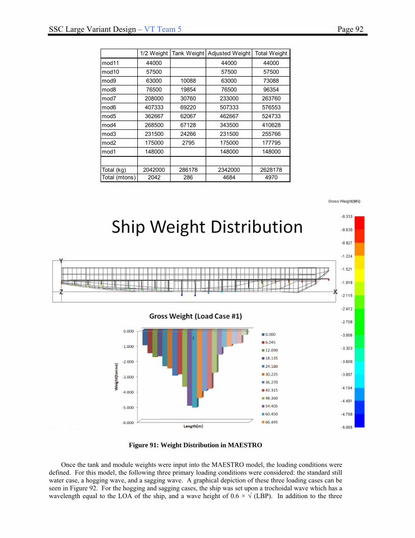
SSC Large Variant Design – VT Team 5 Page 92
1/2 Weight Tank Weight Adjusted Weight Total Weight
mod11 44000 44000 44000
mod10 57500 57500 57500
mod9 63000 10088 63000 73088
mod8 76500 19854 76500 96354
mod7 208000 30760 233000 263760
mod6 407333 69220 507333 576553
mod5 362667 62067 462667 524733
mod4 268500 67128 343500 410628
mod3 231500 24266 231500 255766
mod2 175000 2795 175000 177795
mod1 148000 148000 148000
Total (kg) 2042000 286178 2342000 2628178Total (mtons) 2042 286 4684 4970
Figure 91: Weight Distribution in MAESTRO
Once the tank and module weights were input into the MAESTRO model, the loading conditions were
defined. For this model, the following three primary loading conditions were considered: the standard still water case, a hogging wave, and a sagging wave. A graphical depiction of these three loading cases can be seen in Figure 92. For the hogging and sagging cases, the ship was set upon a trochoidal wave which has a wavelength equal to the LOA of the ship, and a wave height of 0.6 × √ (LBP). In addition to the three

SSC Large Variant Design – VT Team 5 Page 93
standard cases, the green water on the weather deck loading case was also considered. This load case is defined by the US Navy standard for structural loads, which requires a head pressure equal to 3.7 m of water above the weather deck at the forward perpendicular, with the head decreasing linearly to 1.2 m above the weather deck in a line to the design waterline at amidships. This can be seen graphically in Figure 93. A summary of all the loading conditions can be seen in Table 28.
Figure 92: Three Primary Load Cases
Figure 93: Green Seas Loading Condition as Defined by DDS 100

SSC Large Variant Design – VT Team 5 Page 94
Table 28: Four Loading Conditions Tested in the Structural Model
Once the ship is loaded, and the loading conditions have been set for analysis, restraints must be placed upon the ship to provide MAESTRO with certain boundary conditions for loading and testing the structure. These restraints are simple limitations in the movement of the ship for the purpose of the analysis. For this model, the ship was restrained in the vertical direction at both the bow and the stern, and was restrained from movement in the longitudinal direction in the bow. This can be seen graphically in Figure 94.
Figure 94: Constraints on the Structural Model
4.5.3 Adequacy
Once the Finite Element Analysis is run in MAESTRO, the stresses are calculated across the ship. The X Normal, Y Normal, and VonMises stresses are recovered at the neutral axis of the stiffener and plate structure. The shear stress reported for Mid is the Plate Shear stress from the mid-plane of the plate. MAESTRO can recover stresses for a stiffened panel at the mid-plane of the plate (Top), the neutral axis of the plate and stiffener combination (Mid) and the axial stress at the mid-plane of the stiffener flange (Bottom/Stiffener Flange). Graphically this can be seen in Figure 95. These details as well as further descriptions on the calculation of the calculation of the stresses can be found in the MAESTRO help file.

SSC Large Variant Design – VT Team 5 Page 95
Figure 95: Graphical Depiction of how the Stresses are Calculated in MAESTRO
MAESTRO also calculates various adequacy parameters of the structural model. These adequacy
parameters are limit states that define where the structure fails to meet its requirements. There are eleven limit states that examine the panel, seven limit states that examine the girder, and five limit states that examine the frame. These limit states are further categorized by the type of failure that occurs within the structure. The collapse limit states are defined when the structure has failed in its primary, load carrying role. The serviceability limit states are defined when the deterioration of loss of other, less vital functions occurred. The adequacy value is provided in a range from -1 to 1, with 0 being the value of collapse, yield, or failure.
Examining the structural analysis results of the SSC determined that the structural model was over designed in most areas of the design. By examining the output file and the graphical reports, it was determined that the sagging case represented the worst load case for this vessel. Looking closely at the vonMises stress criteria, it can easily be determined that none of the stresses come close to approaching the yield stress of the material. The maximum stresses recorded are around 100 MPa, which can be seen graphically in Figure 96. The maximum yield stress for HSS is 360 MPa, indicating that this design is overly adequate to withstand the stresses simulated.
Figure 96: vonMises Stress Criteria for the Sagging Condition
Further examining the adequacy parameters for this load case, the minimum panel adequacy
parameter showed a few local areas in the bow with inadequate values, however, due to the course mesh of the model and the tightly confined geometry in the bow region, these areas of inadequacy may not be
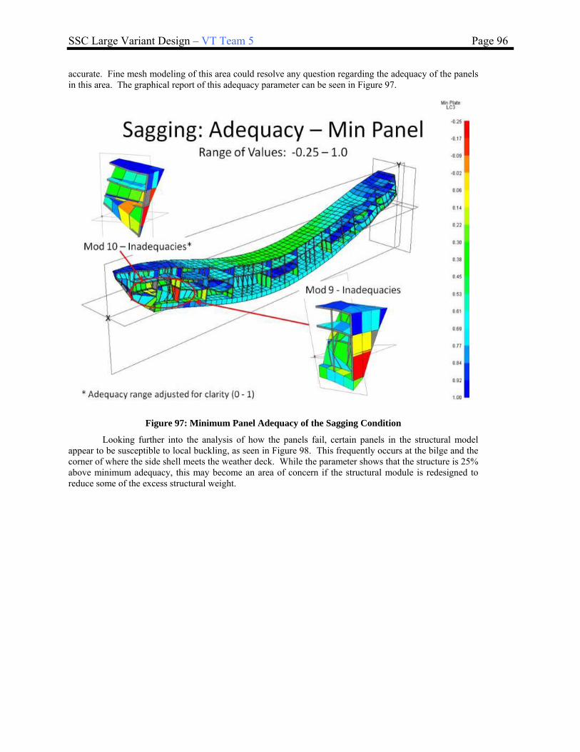
SSC Large Variant Design – VT Team 5 Page 96
accurate. Fine mesh modeling of this area could resolve any question regarding the adequacy of the panels in this area. The graphical report of this adequacy parameter can be seen in Figure 97.
Figure 97: Minimum Panel Adequacy of the Sagging Condition
Looking further into the analysis of how the panels fail, certain panels in the structural model appear to be susceptible to local buckling, as seen in Figure 98. This frequently occurs at the bilge and the corner of where the side shell meets the weather deck. While the parameter shows that the structure is 25% above minimum adequacy, this may become an area of concern if the structural module is redesigned to reduce some of the excess structural weight.

SSC Large Variant Design – VT Team 5 Page 97
Figure 98: Panel Failure, Local Buckling Adequacy Parameter for the Sagging Condition
The beams of the model can also be examined for adequacy, and in the sagging case, there
appeared to be some areas of inadequacy in the girder collapse - tripping condition, as seen in Figure 99. This failure occurs when the stiffeners of a panel collapse inward when the panel is compressed. This is shown in a laboratory experiment in Figure 100. While tripping appears to be a problem in the bow area, additional fine mesh modeling would be required to determine the extent of the tripping.

SSC Large Variant Design – VT Team 5 Page 98
Figure 99: Girder Collapse, Tripping Adequacy Parameter
Figure 100: Photograph of the Tripping Phenomena

SSC Large Variant Design – VT Team 5 Page 99
4.5.4 Revisions and Final Structural Design
Creating structural model and studying the results offer several lessons learned for the next round through the design spiral. First of all, as determined by the low stresses simulated in the structural model, the ship appears to be grossly over designed. There stands to be considerable weight and cost savings by reducing the size and strength of the scantlings used in the structure. Also, by using HSS in the structural members, this will greatly increase the ease of production. HY-80 should only be used in key locations where the higher yield strength would be required such as at the bilge or the corner of the side shell and the weather deck. This, combined with appropriately sized scantlings, will help prevent a local buckling problem. By creating a fine mesh model of the design, a more accurate analysis will be able to be performed and eliminate false areas of inadequacy due to problems with the mesh and the tight geometry.
Also of note, this structural analysis did not take into account the survivability requirements and additional structure that will be required to withstand weapons effects. Those simulations would be required prior to further modification of the structural design.
4.6 Power and Propulsion
In concept development, a more detailed analysis of the total ship resistance at various speeds is conducted. The improved ship resistance profile is used to determine the sustained speed and endurance range of the vessel given the machinery arrangement.
The coupled performance between the main propulsion engines, reduction gears, propulsors, and hull for the improved baseline model are also investigated in the concept development phase. The power and propulsion analysis for the improved baseline model is conducted in Navcad, and the outputs from Navcad are used to calculate the endurance fuel calculations in Mathcad.
The variables used in the propulsion analysis are the propeller and shaft line arrangement, main machinery room locations, propeller shaft angles, propeller diameters, propeller selection, engine speeds and SFC’s, reduction gear ratios, transmission efficiencies, and hull resistance and EHP at the endurance and sustained speeds. The propulsion system modeled and analyzed in Navcad is a 2 shaft CODAG plant. This plant includes 2 LM2500 main gas turbines, 2 CAT3618 secondary propulsion diesel generators, and 4 CAT 3516B ship service diesel generator sets. The endurance condition performance map is input into Navcad and shown below in Figure 101 for the CAT3618 secondary propulsion diesels. The propulsions diesels are large enough to power the ship alone at the endurance speed of 20 kts.

SSC Large Variant Design – VT Team 5 Page 100
Figure 101: Endurance Condition Performance Map
The sustained speed condition performance map is input into Navcad and shown below for the LM2500 primary gas turbines and the CAT3618 secondary propulsion diesels. In order to get the power required to power the ship through the sustained speed regime, all propulsion diesels and gas turbines are online. The combined performance of the CODAG plant with the gas turbines and diesel propulsion engines online is given in Figure 102.

SSC Large Variant Design – VT Team 5 Page 101
Figure 102: Sustained Condition Performance Map
4.6.1 Resistance
In order to complete the power and propulsion analysis, the hull resistance was computed for the improved baseline hullform by using the Holtrop and Mennen resistance prediction method for the selected hullform at the endurance and sustained speed regimes. The location, size, and characteristics of the propellers were obtained from the improved ASSET baseline model along with the engine characteristics, and input into Navcad. The propulsion analysis was then performed in Navcad at the endurance and sustained speeds. Finally, the output from the Navcad propulsion analysis is used to perform the endurance range calculation in Mathcad. The inputs that Navcad requires are the endurance speed conditions, sustained speed conditions, hullform principle particulars from the finalized hullform, appendage wetted areas from the ASSET improved baseline model, environmental resistance information (wind profile, sail area, seaway definition, etc), and endurance and sustained speed design margins (10% on endurance and 25% on sustained speed). The total ship resistance calculation in Navcad uses the Holtrop and Mennen resistance prediction method (1984) at the endurance and sustained speeds. This method approximates the bare hull viscous skin friction drag and the wave making drag. The total ship resistance is a summation of the viscous drag using the ITTC friction line, wave making drag from the force required to move the water around the hull, appendage drag of the propellers and other underwater appendages, sonar dome drag, air drag, and transom drag. The total ship resistance is calculated at the endurance and sustained speeds, and the effective powers are calculated. The calculated effective powers include a 10% design margin for endurance, and a 25% design margin for the sustained speed. The Navcad calculated total ship resistance for the large SSC for the endurance speed of 20 kts is given in Figure 103 and the endurance speed calculated effective power is shown in Figure 104.
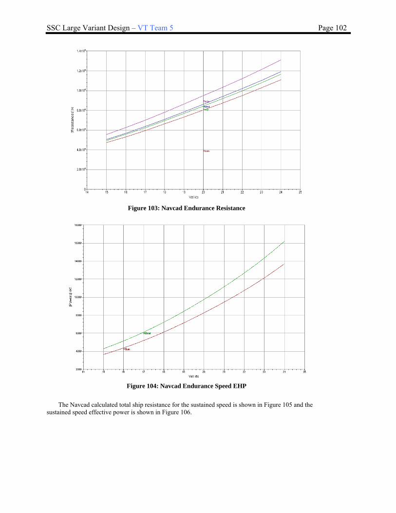
SSC Large Variant Design – VT Team 5 Page 102
Figure 103: Navcad Endurance Resistance
Figure 104: Navcad Endurance Speed EHP
The Navcad calculated total ship resistance for the sustained speed is shown in Figure 105 and the sustained speed effective power is shown in Figure 106.

SSC Large Variant Design – VT Team 5 Page 103
Figure 105: Navcad Sustained Speed Resistance
Figure 106: Navcad Sustained Speed EHP
4.6.2 Propulsion Analysis – Endurance Range and Sustained Speed
Propeller data from the improved ASSET baseline model was also input into Navcad for the endurance and sustained speed analysis. The large SSC propulsor information is shown in Figure 107 for the endurance condition.

SSC Large Variant Design – VT Team 5 Page 104
Figure 107: Endurance Range Propulsor Sizing
The Navcad calculated endurance shaft power per shaft for the endurance speed of 20 kts is shown in Figure 108.

SSC Large Variant Design – VT Team 5 Page 105
Figure 108: Endurance Condition Propulsion Shaft Power
The Navcad calculated overall propulsive coefficient (OPC) for the endurance condition is presented in Figure 109.
Figure 109: Endurance Condition OPC
The shaft power is then used to calculate the total brake power required per shaft in the endurance condition by dividing the assumed shaft and line shaft bearing efficiencies. The plot of the required brake power required per shaft is given in Figure 110.

SSC Large Variant Design – VT Team 5 Page 106
Figure 110: Endurance Condition Required Brake Power
The propulsors were sized for the sustained speed condition in Navcad, and that information is given in Figure 111.

SSC Large Variant Design – VT Team 5 Page 107
Figure 111: Sustained Speed Propulsor Sizing
The Navcad calculated propulsion shaft power per shaft is presented in Figure 112.

SSC Large Variant Design – VT Team 5 Page 108
Figure 112: Sustained Speed Condition Propulsion Shaft Power
The Navcad calculated OPC in the sustained speed condition is shown in Figure 113. It is worthwhile to note that the OPC calculated by Navcad for the sustained speed is unrealistically high. The typical range of OPC’s for surface ships is 0.4-0.7. The reason for the unrealistically high OPC’s in the sustained speed regime is not readily apparent. It is recommended that the Navcad OPC calculation be investigated in more detail in the future.
Figure 113: Sustained Speed Condition OPC
The shaft power is then used to calculate the total brake power required per shaft in the sustained speed condition by dividing the assumed shaft and line shaft bearing efficiencies. The plot of the required brake power required per shaft is given in Figure 114.
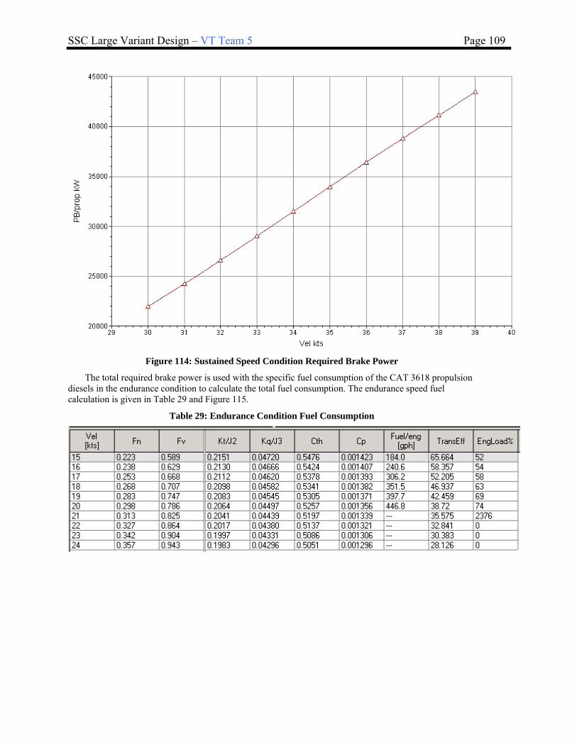
SSC Large Variant Design – VT Team 5 Page 109
Figure 114: Sustained Speed Condition Required Brake Power
The total required brake power is used with the specific fuel consumption of the CAT 3618 propulsion diesels in the endurance condition to calculate the total fuel consumption. The endurance speed fuel calculation is given in Table 29 and Figure 115.
Table 29: Endurance Condition Fuel Consumption

SSC Large Variant Design – VT Team 5 Page 110
Figure 115: Endurance Condition Fuel Consumption
The output from the Navcad propulsion analysis was used to calculate the endurance range for the large SSC at 20 kts in Mathcad. The inputs needed for the endurance range calculation are given below:
1). Endurance speed 2). Brake power installed at endurance 3). Brake power required at endurance 4). Number of propulsion diesels required at endurance 5). Propulsion diesel fuel consumption at endurance 6). Number of ship service diesels at endurance 7). Total ship service KW installed 8). 24 Hr cruise electric load 9). Ship service generator SFC in cruise condition 10). Total fuel oil volume
These inputs are used to calculate the range of the ship in the endurance condition. The calculation below shows that the large SSC has an endurance range of 3589 nm. This assumes a tailpipe allowance of 5% to account for unburnable fuel, a 5 % volume allowance for fuel expansion in the tanks, a 2% volume allowance for the internal structure within the tanks, a 5% plant deterioration factor, and instrumentation inaccuracy and machinery design changes for the ship service and propulsion power. The full Mathcad calculation for endurance range is given in Appendix G.

SSC Large Variant Design – VT Team 5 Page 111
4.6.3 Electric Load Analysis (ELA)
An electric load analysis (ELA) was conducted in order to determine the total ship service electric load in the battle, cruise, in port, and emergency conditions. The total electric load for each of these conditions was broken down into the total electric load required for each 3 digit SWBS group. The ELA was completed by using data from the ASSET improved baseline model and the SSSM. The breakdown of the ship service electric loads required in each of the operational conditions is given in Table 30. The maximum electric load is in the battle condition, and is 3897 kW. The US Navy has an N-1 criterion that states that the highest ship service electric load must be met with one generator down for maintenance or repair. The SSC satisfies this criterion because it can supply the highest ship service load with 3 CAT 3516B diesel generators online, and one generator down for maintenance or repair.
Table 30 - Electric Load Analysis Summary
Connected Load
SWBS Description (kW)Power Factor (kW)
Power Factor (kW)
100 Deck Machinery 790 0.00 790 0.00 790200 Propulsion 469 1.00 399 1.00 246
Propulsion Direct 29 1.00 29 0.15 11
Propulsion support 440 0.84 370 0.16 235300 Electric 443 0.67 297 0.24 224
400 CCC 1629 617 475Combat Systems 1599 0.37 588 0.28 450Miscellaneous 29 0.63 29 0.29 25
500 Auxiliary 5172 1704 1614510 CPS/HVAC 2322 0.36 696 0.39 904
520 Sea Water Systems 312 0.34 106 0.29 91530 Fresh Water System 244 0.56 49 0.60 147540 Fuel Handling 600 0.34 204 0.17 102
550 Air System 1693 0.95 589 0.18 308560 Ship Centra l Sys 59 0.95 56 0.95 56
590 Special Purpose 50 0.10 5 0.10 5600 Services 224 0.10 50 0.40 90700 Weapons 122 0.34 41 0.33 35
Total Required 8848 3897 347224 Hour Average 1895 1976 1671
Number Generator Rating (kW)
Average Connected (kW) Online (kW) Online (kW)
4 CAT 3516B 1491.0 5964 3 4473 3 4473Total 5964 4473 4473
Available Power 576 1001
Battle Cruise

SSC Large Variant Design – VT Team 5 Page 112
Connected Load
SWBS Description (kW)
100 Deck Machinery 790200 Propulsion 469
Propulsion Direct 29Propulsion support 440
300 Electric 443400 CCC 1629
Combat Systems 1599Miscellaneous 29
500 Auxiliary 5172510 CPS/HVAC 2322520 Sea Water Systems 312530 Fresh Water System 244540 Fuel Handling 600550 Air System 1693560 Ship Central Sys 59590 Special Purpose 50600 Services 224700 Weapons 122
Total Required 884824 Hour Average 1895
Number Generator Rating (kW)
Average Connected (kW)
4 CAT 3516B 1491.0 5964Total 5964
Available Power
Power Factor (kW)
Power Factor (kW)
Power Factor (KW)
1.00 790 0.5 395 0.0 79071 0 69
0.02 20 0.0 0 0.0 180.03 51 0.0 0 0.0 520.15 213 0.4 212 0.1 85
233 3 2520.10 221 0.0 0 0.1 2430.10 13 0.1 3 0.1 10
1433 977 4380.40 860 0.0 860 0.1 2490.30 91 0.4 91 0.3 1060.60 147 0.0 0 0.3 220.25 20 0.1 20 0.0 00.20 308 0.0 0 0.0 0
0 0 560.15 6 0.2 6 0.2 60.40 70 0.4 70 0.0 10.30 33 0.0 0 0.0 10
2842 1657 16461307 790 751
Online (kW) Online (kW) Online (KW)
2 2982 2 2982 2 29822982 2982 2982
140 1325 1336
EmergencyAnchor In Port
4.7 Mechanical and Electrical Systems and Machinery Arrangements
Mechanical and electrical systems are selected based on mission requirements, standard naval requirements for combat ships, and expert opinion. A Machinery Equipment List (MEL), was created using inputs from the ASSET improved baseline model and SSSM, with modifications due to design refinement. The MEL of major mechanical and electrical systems includes quantities, dimensions, weights, and location is provided in Appendix D.
The physical dimensions of all the major propulsion and auxiliary equipment were taken from the MEL, and modeled in 3D in the hull subdivision Rhino model. The main propulsion gas turbines and diesels were first modeled with their required maintenance envelopes, and then their respected intakes and uptakes were modeled. The propulsion shaft lines were then modeled in Rhino in order to arrange the reduction gears, thrust bearings, line shaft bearings, propeller shafts, and propellers. Then, the ship service diesel generators and their intakes and uptakes were added. The propulsion related auxiliaries were then added to the main machinery spaces, and the non-propulsion related auxiliaries were added to the AMR’s. By modeling all of the machinery contained in the MEL in 3D, potential interferences were avoided, and it was proven that the machinery will fit within the main and auxiliary machinery rooms. The modeled 3D machinery arrangements can be found in Figure 116 through Figure 120.

SSC Large Variant Design – VT Team 5 Page 113
Figure 116: Machinery Space Arrangements with Intakes and Uptakes
Figure 117: AMR 1 Machinery Arrangement
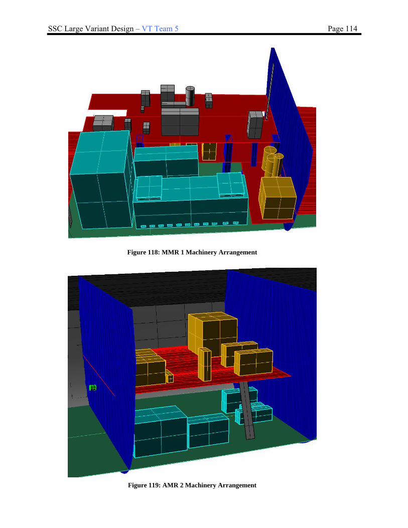
SSC Large Variant Design – VT Team 5 Page 114
Figure 118: MMR 1 Machinery Arrangement
Figure 119: AMR 2 Machinery Arrangement

SSC Large Variant Design – VT Team 5 Page 115
Figure 120: MMR 2 Arrangement
4.7.1 Ship Service Power and Electrical Distribution
The ship service power distribution system for the large SSC can be summarized by the one line diagram contained in Figure 121. There are 4, CAT 3516B diesel generator sets that generate ship service power adequate to power the maximum ship service electric load contained in Table 30 with one generator down for maintenance or repair.
These generators will power a 400 VAC zonal electric distribution system. This is a redundant system, and has good survivability characteristics. Each of the 4 ship service diesel generators will power a switchboard that will power the port BUS and starboard BUS. Within each zone, there are load centers for each BUS that will transform and power the ship service electric loads.
Gen Set No. 1
Gen Set No. 2
Gen Set No. 3
Gen Set No. 4
SWBD No. 1
SWBD No. 2
SWBD No. 3
SWBD No. 4
Bus Tie Circuit Breakers
AMR1
MMR1
AMR2
MMR2
Starboard Bus400 VAC ZEDS
Port Bus400 VAC ZEDS
Figure 121 - One-Line Electrical Diagram
Future work should include a more detailed electric load analysis and one-line diagram. Switchboards, BUS cables, BUS transfers, load centers, and PCM’s would need to selected in a future design refinement.

SSC Large Variant Design – VT Team 5 Page 116
4.7.2 Main and Auxiliary Machinery Spaces and Machinery Arrangement
After the 3D machinery arrangements were modeled in Rhino, a series of 2D plan view drawings were created for each level of the main and auxiliary machinery spaces. In these drawings, the machinery is labeled with a find number so that it can be identified with the MEL found in Appendix D. The 2D machinery arrangement drawings are located in Figure 122 .
2nd Plat
1st Plat
2nd Plat
1st Plat
2nd Deck2nd Deck
1st Plat
2nd Plat
1st Plat
2nd Plat
MMR 2
AMR 2
MMR 1
AMR 1
Figure 122: 2D Arrangement Drawings
4.8 Manning
In order to establish a manning estimate and profile for the large SSC, a hierarchy chart and table to assign personnel to the divisions and departments. The manning estimate from the concept exploration phase was used as a starting point with the goal of minimizing manning, and the feasibility of the manning profile was examined.
First, the hierarchy chart was developed to determine where personnel will be assigned. A typical manning breakdown for a naval surface combatant is given in Figure 123.

SSC Large Variant Design – VT Team 5 Page 117
Figure 123: Naval Ship Departments and Divisions
The large SSC surface combatant manning estimate was established by determining the minimum number of personnel required to perform the missions outlined in the ADM, and fill the departments listed above. These personnel are distributed among the executive, operations, weapons, engineering, and supply departments. The manning profile for the large SSC is given in Table 31. This manning profile assumes condition III (3 watch sections), with an automated bridge, and an engineering control station for primary propulsion control on the bridge. The manning triad was also considered when determining the minimum crew for the large SSC. The functions contained in the manning triad are watch standing, maintenance, and damage control.
Table 31: Manning Profile
The manning profile outlined in Table 31 is an optimized manning profile that is just meets the requirements of the manning triad. The following technologies will be designed into the large SSC in order to enable the minimum crew to perform and all of the required missions for the ship some of these technologies are listed below:
• Computers / CD-ROM / software
• GUI’s

SSC Large Variant Design – VT Team 5 Page 118
• Large flat panel displays
• Expert systems
• Reliable sensors
• Fiber optics
• Corrosion and wear-resistant coatings
• Watch-standing technology
– GPS
– Automated route planning
– Electronic charting and navigation (ECDIS)
– Collision avoidance
– Electronic log keeping
• Video teleconferencing - provides shipboard experts
• Personal Access Display Devices (PADDs)
• Condition-based maintenance
– ICAS - Integrated Condition Assessment System
– Trend-analysis
– Expert assistance
– Link to Interactive Electronic Tech Manuals (IETMs) / Gold Discs (automated troubleshooting)
• Integrated Survivability Management System (ISMS)
• Preservation - coatings costly, but cost-effective
– Unicoat - 300% improvement in life expectancy, self-priming, 50% reduction in paint time, 50% reduction in VOC’s
• Training - multimedia; embedded
• Paperless ship - Most Admin / personnel ashore
• Standard consoles/ integrated networks
• Personnel locators / active badges
• Automated mess
Future - Autonomic Ship (parts function automatically below level of consciousness) – not ready yet!
• Bridge in CIC - Command Center
• Large screen displays, 360 degree coverage, multiple magnifications and spectra
• Main control - Command Center II
• Unmanned machinery spaces; no sound & security
• virtual presence
• IR imaging (through smoke)
• robot arms for fire suppression, rigging, DC
• DC robots / virtual reality display
4.9 Space and General Arrangements

SSC Large Variant Design – VT Team 5 Page 119
Space and General Arrangements were completed in Rhino to ensure that there is adequate arrangeable area and volume within the hull envelope to meet the requirements of the improved baseline SSCS. To do this required coordination between the subdivisions created in HECSALV, general arrangements, machinery arrangements and topside arrangements. The deliverables from these objectives are complete General Arrangements drawings which include inboard and outboard profiles and deck plans (weather deck, deckhouse decks) and arrangements for typical officer and crew berthing, messing and sanitary spaces
HECSALV and Rhino are used to generate and assess subdivision and arrangements. HECSALV is used for primary subdivision, tank arrangements and loading. Rhino is used for the 3-D geometry and to construct 2-D drawings of the inboard and outboard profiles, deck and platform plans, detailed drawings of berthing, sanitary, and messing spaces.
4.9.1 Internal Arrangements
Figure 124: Inboard Profile
Figure 125: Internal Arrangements – Deckhouse 04 and 03
04 Level
03 Level

SSC Large Variant Design – VT Team 5 Page 120
Figure 126: Internal Arrangements – Deckhouse 02 and 01
Figure 127: Internal Arrangements – Main Deck Deckhouse
Main Deck Level
01 Level
02 Level

SSC Large Variant Design – VT Team 5 Page 121
Figure 128: Internal Arrangements – Main Deck and 2nd Deck Plan View
Figure 129: Internal Arrangements – 1st Platform, 2nd Platform, Bottom Tanks Plan View
1st Platform Level
2nd Platform Level (Inner Bottom)
Bottom Tanks
Main Deck Level
2nd Deck Level

SSC Large Variant Design – VT Team 5 Page 122
Figure 130: Internal Arrangements – Main Deck, 2nd Deck Plan View (foreword)
Figure 131: Internal Arrangements – Main Deck, 2nd Deck Plan View (aft)
Main Deck Level
2nd Deck Level
Main Deck Level
2nd Deck Level

SSC Large Variant Design – VT Team 5 Page 123
Figure 132: Internal Arrangements – 1st and 2nd Platform Plan View (foreword)
Figure 133: Internal Arrangements – 1st and 2nd Platform Plan View (aft)
1st Platform Level
2nd Platform Level (Inner Bottom)
1st Platform Level
2nd Platform Level (Inner Bottom)

SSC Large Variant Design – VT Team 5 Page 124
Figure 134: Internal Arrangements – Bottom Tanks Plan View (foreword)
Figure 135: Internal Arrangements – Bottom Tanks Plan View (aft)
4.9.2 Living Arrangements
The SSC has accommodations for 65 personnel. These personnel include 1 Executive Officer, 1 Commanding Officer, 19 Officers, 19 Chief Petty Officers, and 25 enlisted members. The SSC can accommodate up to 20 extra crew members which allows for members of mission modularity crews. This brings the maximum available accommodations to 85 people. Space allocated for the crew was determined by following US Navy habitability standards. The accommodation space required for the ships force is listed in Table 32.
Table 32: Crew Berthing Space Allocation
Item Accomodation Quantity Per Space Number of Spaces Area Each (m2)Total Area
(m2)
CO 1 1 1 37.3 37.3XO 1 1 1 13.9 13.9
Flag Officer 1 1 1 15 15
Department Head 4 1 4 11.6 46.4
Other Officer 18 2 9 12.5 112.5
CPO 25 5 5 13.64 68.2
Enlisted 35 18 2 40 80
Officer Sanitary 25 5 5 4 20
CPO Sanitary 25 5 5 4 20
Enlisted Sanitary 35 18 2 7 14
Total 35 427.3
A total of 35 crew berthing and sanitary spaces were added to the general arrangement. These berthing spaces are sufficient for a crew of 85. The planned minimum crew for the SSC is only 65 personnel, but berthing spaces for mission detachments was provided in the general arrangements.
The enlisted berthing spaces were concentrated on the 1st platform just aft of MMR 2. The officer berthing spaces are separated from the enlisted quarters, and are contained within the deckhouse. Officer and CPO berthing spaces contain fewer berths then enlisted spaces. The berthing spaces were located away from machinery spaces where possible to reduce airborne noise in the berthing spaces. This will reduce the amount of acoustic insulation
Bottom Tanks
Bottom Tanks

SSC Large Variant Design – VT Team 5 Page 125
required. The following figures show a typical arrangement for officer and crew berthing, officer and crew sanitary spaces, as well as officer and crew mess rooms.
Figure 136: Living Arrangements – Typical Officer Berthing
Figure 137: Living Arrangements – Typical Crew Berthing

SSC Large Variant Design – VT Team 5 Page 126
Figure 138: Living Arrangements – Typical Crew Sanitary Space
Figure 139: Living Arrangements – Typical Officer Mess Room

SSC Large Variant Design – VT Team 5 Page 127
Figure 140: Living Arrangements – Typical Crew Mess Room
4.9.3 External Arrangements
Figure 108 shows that the SSC is equipped with a 57 mm deck gun and a 32 cell MK 41 VLS System. There is also a helicopter landing pad, as well as a helicopter hanger that can accommodate up to 2 SH-60 helicopters. All of the intakes and exhausts, as well as the radar and communication antennas, are stealthily hidden within the confinements of the deckhouse. This gives the ship a much reduced radar cross section.
Figure 141: External Arrangements

ASC Design – VT Team 2 Page 128
4.9.4 Area and Volume
Throughout the General Arrangement process, it was important that enough space was used for each of the compartments within the ship. The area and/or volume of each compartment has been calculated and checked against the asset baseline numbers generated for the ship. Most of the compartments exceed the baseline ASSET numbers. A comparison between the ASSET required areas and volumes and the actual areas and volumes can be found in Appendix F.
4.10 Weights, Loading and Stability
4.10.1 Lightship Weights
The 3 digit weight breakdown from the ASSET improved baseline was modified throughout the concept development phase to include deviations from the baseline design. A summary of the lightship weights and centers for the SSC can be found in Table 33. A full 3 digit breakdown of the lightship weights and centers can be found in Appendix E.
Table 33 - Lightship Weight Summary SWBS Group Weight (MT) VCG (m-Abv BL) LCG (m-Aft FP)
100 1695.1 6.0 63.5 200 840.8 3.2 77.1 300 366.8 7.3 64.8 400 168.0 8.0 46.5 500 600.6 7.7 66.0 600 33.2 2.7 75.2 700 104.7 6.3 38.7
Margin 380.9 6.35 78.3 Total (LS) 4190.1 6.35 78.3
4.10.2 Loads and Loading Conditions
Full Load and Minimum Operating loading conditions were determined for the SSC by using the guidance contained in the US Navy Design Data Sheet 079-1. DDS 079-1 describes the Full Load condition by the summary given in Table 34, and the DDS 079-1 MinOp Condition definition is given in Table 35.
Table 34: DDS 079-1 Full Load Condition Definition
Crew and Effects Wartime Complement
Stores Full Design Complement
Ammunition Full Allowance
Lube Oil Storage 95%, Settling empty
Fresh Water All tanks 100% full
Aviation Fuel All tanks 95% full
Propulsion Fuel All tanks 95% full
Water Ballast Empty
Table 35: DDS 079-1 MinOp Condition Definition
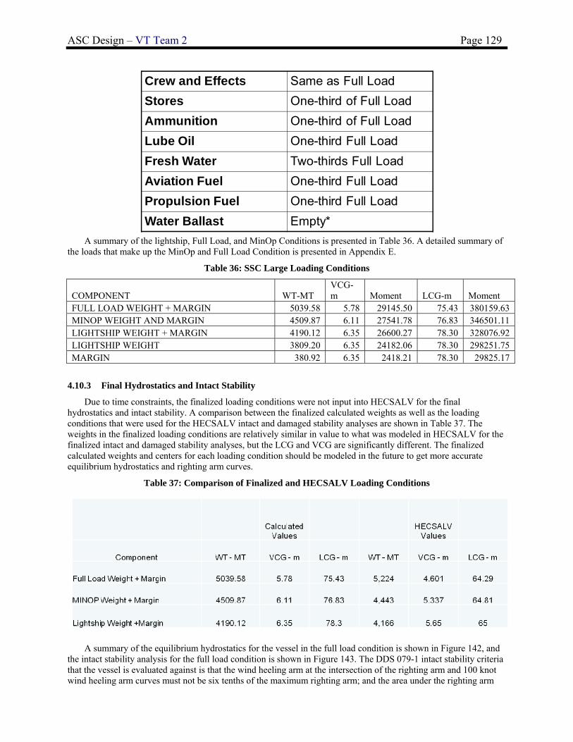
ASC Design – VT Team 2 Page 129
Crew and Effects Same as Full Load
Stores One-third of Full Load
Ammunition One-third of Full Load
Lube Oil One-third Full Load
Fresh Water Two-thirds Full Load
Aviation Fuel One-third Full Load
Propulsion Fuel One-third Full Load
Water Ballast Empty*
A summary of the lightship, Full Load, and MinOp Conditions is presented in Table 36. A detailed summary of the loads that make up the MinOp and Full Load Condition is presented in Appendix E.
Table 36: SSC Large Loading Conditions
COMPONENT WT-MT VCG-m Moment LCG-m Moment
FULL LOAD WEIGHT + MARGIN 5039.58 5.78 29145.50 75.43 380159.63 MINOP WEIGHT AND MARGIN 4509.87 6.11 27541.78 76.83 346501.11 LIGHTSHIP WEIGHT + MARGIN 4190.12 6.35 26600.27 78.30 328076.92 LIGHTSHIP WEIGHT 3809.20 6.35 24182.06 78.30 298251.75 MARGIN 380.92 6.35 2418.21 78.30 29825.17
4.10.3 Final Hydrostatics and Intact Stability
Due to time constraints, the finalized loading conditions were not input into HECSALV for the final hydrostatics and intact stability. A comparison between the finalized calculated weights as well as the loading conditions that were used for the HECSALV intact and damaged stability analyses are shown in Table 37. The weights in the finalized loading conditions are relatively similar in value to what was modeled in HECSALV for the finalized intact and damaged stability analyses, but the LCG and VCG are significantly different. The finalized calculated weights and centers for each loading condition should be modeled in the future to get more accurate equilibrium hydrostatics and righting arm curves.
Table 37: Comparison of Finalized and HECSALV Loading Conditions
A summary of the equilibrium hydrostatics for the vessel in the full load condition is shown in Figure 142, and the intact stability analysis for the full load condition is shown in Figure 143. The DDS 079-1 intact stability criteria that the vessel is evaluated against is that the wind heeling arm at the intersection of the righting arm and 100 knot wind heeling arm curves must not be six tenths of the maximum righting arm; and the area under the righting arm

ASC Design – VT Team 2 Page 130
curve (A1) must be at least 1.4 times the area under the wind heeling curve (A2). Figure 143 shows that the vessel meets the intact stability criteria of DDS 079-1 by a large margin. It is unlikely that the change in the weight and centers for the finalized calculated condition would cause the vessel to fail the intact stability criteria.
Figure 142: Full Load Equilibrium Condition
Figure 143: Full Load Condition Intact Stability
A summary of the equilibrium hydrostatics for the vessel in the MinOp condition is shown in Figure 142, and the intact stability analysis for the full load condition is shown in Figure 144. The DDS 079-1 intact stability criteria that the vessel is evaluated against is that the wind heeling arm at the intersection of the righting arm and 100 knot
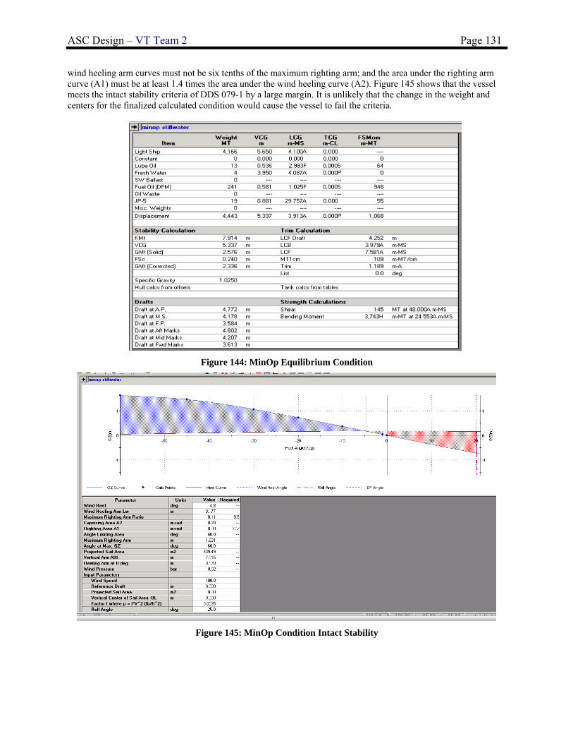
ASC Design – VT Team 2 Page 131
wind heeling arm curves must not be six tenths of the maximum righting arm; and the area under the righting arm curve (A1) must be at least 1.4 times the area under the wind heeling curve (A2). Figure 145 shows that the vessel meets the intact stability criteria of DDS 079-1 by a large margin. It is unlikely that the change in the weight and centers for the finalized calculated condition would cause the vessel to fail the criteria.
Figure 144: MinOp Equilibrium Condition
Figure 145: MinOp Condition Intact Stability

ASC Design – VT Team 2 Page 132
4.10.4 Damage Stability
The damaged stability of the vessel was evaluated for each of the loading conditions contained in Table 37. Again, these loading conditions as defined for the HECSALV damaged stability analysis are somewhat dated because the finalized calculated weights and centers for the three loading conditions are somewhat different than what was modeled in HECSALV. It is recommended that future work be completed to update the HECSALV loading conditions, and then re-run the intact and damaged stability analyses.
Transverse watertight bulkheads were previously spaced to ensure that the floodable length requirements were met. This subdivision resulted in a total of 11 watertight hull segments. The Full Load and MinOp conditions were evaluated against the damaged stability criteria contained in DDS 079-1 using a 15% damaged length along the hull. A total of 38 damaged cases (19 per load case) were developed within HECSALV, and a damaged stability analysis was run for each damaged case. Damage was assumed to extend past centerline and from the keel to the weather deck. Some of the damaged cases that were calculated in HECSALV are shown in Figure 146.
Figure 146: HECSALV Damaged Cases
The DDS 079-1 damaged stability criteria that were used to evaluate the vessel were that the static heel after damage must not exceed 15 degrees, the margin line must not be submerged, and the remaining dynamic stability after damage must be adequate (A1 > 1.4 A2).
The worst case analyzed is for forward damage between FR 22.9 and FR 58.9 in the Full Load Condition. This damage case causes a trim by the bow that greatly reduced the waterplane area and transverse moment of inertia of the waterplane. The equilibrium condition for this damage case is presented in Figure 147. The corresponding righting arm curve for this damaged case with a 33 knot heeling wind is shown in Figure 148. This figure shows that the vessel meets the damaged stability criteria of DDS 079-1 by a large margin for the worst case damage scenario. It is unlikely that the change in the weight and centers for the finalized calculated condition would cause the vessel to fail the criteria.

ASC Design – VT Team 2 Page 133
Figure 147: Worst Damaged Case Equilibrium Condition
Figure 148: Worst Damaged Case Damaged Stability
4.11 Seakeeping, Maneuvering and Control
Follow Assignment T26. Use everything – convert bulleted slides to text and include all Figures and Tables.
4.12 Cost and Risk Analysis
The Capability Development Document for the large SSC established a cost cap of $300 million for follow ship acquisition with an absolute cost cap of $400 Million. It is expected that 50 ships will be built in this class. The cost model predicts a lead ship cost of $845 million for the lead ship and $665 million for follow ship acquisition.
The total cost to the Navy for acquisition and ownership of the ship throughout the useful life of the ship is known as the Life Cycle Costs (LCC). The LCC is composed of research and development costs, ship acquisition, operations and support costs, and the cost of disposal. The operational costs associated with operating a ship are generally the highest, and that is why there has been an increased effort made in recent years to reduce manning on naval surface combatants.

ASC Design – VT Team 2 Page 134
The total lead ship cost for a vessel can be decomposed into the following sub categories. These costs can be broken down into constructions costs incurred in the shipyard, and post delivery costs (IPDA) incurred during a post shakedown availability (PSA) period.
Figure 149: Total Lead Ship Acquisition Costs
The cost model for lead and follow ship acquisition were based primarily on the SWBS weight group weights. A labor cost is calculated for each SWBS by multiplying the weight of the three digit SWBS group by a labor rate and work complexity factor. Labor costs for each three digit SWBS group were then added to a material cost for each SWBS group. The material costs were determined by taking the weight of the three digit SWBS group and multiplying it by another complexity factor and an average inflation factor. The direct cost for each three digit SWBS group was then calculated by adding together the total labor and material costs for each group. A summary of the direct SWBS costs versus weight is given in Table 38.
Table 38: SWBS Weight vs. Cost
SWBS Total Weight (LTons) Total Weight % Cost ($Millions)
100 1668.20 36.88 18.19
200 829.50 18.34 48.80
300 361.00 7.98 38.72
400 165.30 3.65 11.98
500 597.70 13.21 60.98
600 370.00 8.18 28.79
700 110.10 2.43 1.49
Margin 421.60 9.32 21.48
Total 4523.40 100.00 230.43
This table shows that the summation of the total shipyard construction costs for all of the SWBS weight groups
is $230 million. The other costs that are included as shipbuilder costs that the Navy will pay in a fixed price contract

ASC Design – VT Team 2 Page 135
are the costs listed above in addition to Integration and Engineering Costs (SWBS 800), Ship Assembly and Support (SWBS 900), costs associated with changing the detailed design, and a 10% profit on the lightship construction costs. The total costs incurred by the shipyard for lead ship acquisition are detailed in Table 39. The total costs incurred by the shipyard for lead ship construction is $406 million.
Table 39: Lead Ship Shipyard Costs
Items Cost ($Millions)
SWBS Total 230.43
800 78.34
900 20.96
Total LS 329.71
Profit 32.97
Shipbuilder Price 362.68
Change Orders 43.52
Total Shipbuilder Portion 406.20
There are other costs associated with lead ship acquisition that the government will pay. These costs include construction support, Program Manager’s growth, Government Furnished Equipment (GFE) for payload and H, M, & E, and other miscellaneous outfitting costs. Costs incurred by the government for lead ship acquisition are detailed in Table 40.
Table 40: Lead Ship Government Costs
Items Cost ($Millions)
Other Support 9.07
Program Managers Growth 32.40
Payload GFE 354.17
HM&E GFE 7.25
Outfitting 14.51
Total Government Portion 421.27
The total lead ship cost is a summation of the shipyard construction costs, government construction costs, and
IPDA costs associated with work completed during the PSA period. The total lead ship cost of $846 million is broken down in Table 41.
Table 41: Total Lead Ship Acquisition Cost

ASC Design – VT Team 2 Page 136
Items Cost ($Millions)
Total Shipbuilder Portion 406.20
Total Government Portion 421.27
Total Lead Ship End Cost 827.47
Post Delivery Cost 18.13
Total Lead Ship Acquisition Cost 845.61
The follow ships in the class will be lower than the lead ship acquisition cost because there will be less non-recurring engineering, reduced change orders, and production efficiencies will be improved due to a reduced learning curve in the shipyard. Lead versus follow ship acquisition costs for the shipyard are detailed in Table 42. A summary of lead versus follow ship acquisition costs for the government is shown in Table 43.
Table 42: Lead vs. Follow Ship Shipyard Acquisition Costs
Follow Ship Cost ($M) Lead Ship Cost ($M)
SWBS 216.59 230.43
800 23.96 78.34
900 19.70 20.96
Total FS Construction 260.25 329.71
Profit 26.03 32.97
Shipbuilder Price 286.28 362.68
Change Orders 29.01 43.52
Total Shipbuilder Portion 315.29 406.20
Table 43: Lead vs. Follow Ship Government Acquisition Costs
Follow Ship Cost ($M) Lead Ship Cost ($M)
Other Support 7.16 9.07
Program Managers Growth 14.31 32.40
Payload GFE 331.40 354.17
HM&E GFE 5.73 7.25
Outfitting 11.45 14.51
Total Government Portion 370.05 421.27
The total direct acquisition cost for follow ship acquisition is $665 million as detailed in Table 44.
Table 44: Total Direct Acquisition Cost

ASC Design – VT Team 2 Page 137
Follow Ship Cost ($Mil) Lead Ship Cost ($Mil)
Total Shipbuilder Portion 315.29 406.2
Total Government Portion 370.05 421.27
Total Lead Ship End Cost 685.34 827.47
Post Delivery Cost 14.31 18.13
Total Ship Acquisition Cost 699.65 845.61
Average Ship Acquisition Cost 665.29
The Life Cycle Cost (LCC) for the ship is the total discounted cost of owning, operating, maintaining, and
disposing of the ship. Once all of the pertinent costs have been determined and calculated, they are discounted to their present value to generate the total LCC costs of the proposed ship. The undiscounted and discounted life cycle costs include R&D, investment, operations and support, and the residual value. These undiscounted and discounted costs are detailed in Table 45. Undiscounted LCC for a large SSC will total $93 billion, and discounted LCC will total $14.8 billion. This is a discount rate of 0.16.
Table 45: Undiscounted Life Cycle Costs
Undiscounted ($Mil) Discounted ($Mil)
R&D 714.55 836.94
Investment 41,579.00 11,948.00
Operations & Support 52,843.00 2,040.00
Residual Value 2,099.00 13.01
Total 93,037.00 14,811.00

ASC Design – VT Team 2 Page 138
5 Conclusions and Future Work
5.1 Assessment
Table 46 compares the CDD KPP’s with the performance of the finalized design.
Table 46 - Compliance with Operational Requirements
Technical Performance
Measure
CCD KPP (Threshold)
Original Goal Improved Baseline
Final Baseline
AAW
ICMS, MK XII AIMS IFF, COMBAT DF, 2X-MK 137
LCHRs, AIEWS ADVANCED
SEW SYSTEM, AN/SPY-1E MFR, GLYCOL WATER COOLING SYSTEM FOR
SPY
AAW Self Defense Only
ICMS, MK XII AIMS IFF, COMBAT DF, 2X-MK 137 LCHRs,
AIEWS ADVANCED
SEW SYSTEM, AN/SPY-1E MFR, GLYCOL WATER
COOLING SYSTEM FOR SPY
ICMS, MK XII AIMS IFF, COMBAT DF, 2X-MK 137 LCHRs,
AIEWS ADVANCED SEW SYSTEM,
AN/SPY-1E MFR, GLYCOL WATER
COOLING SYSTEM FOR SPY
ASUW
IRST, AN/SPS-73, Small Arms Ammo, 2x50-cal MGs, Small Arms Locker, DORNA EO/IR Fire Control, 57 mm
MK 3, 57mm stowage, 57mm ammo in gun
mount(120), 57mm ammo magazie (880), 1x7m RHIB
SSC SAGs could provide defense against mine threats,
littoral ASW threats
IRST, Small Arms Ammo, 2x50-cal
MGs, Small Arms Locker, DORNA
EO/IR Fire Control, 57 mm MK 3, 57mm
stowage, 57mm ammo in gun
mount(120), 57mm ammo magazie (880),
1x7m RHIB
IRST, Small Arms Ammo, 2x50-cal MGs,
Small Arms Locker, DORNA
EO/IR Fire Control, 57 mm MK 3, 57mm
stowage, 57mm ammo in gun
mount(120), 57mm ammo magazie (880),
1x7m RHIB
ASW
SQQ-89 Underwater Fire Control, AN/SLQ-25A
(NIXIE) and AN/SLR-24I (TRIPWIRE), 2x Mk 32
SVTT on deck, NDS 3070 Vanguard mine sonar, SQS-
56 sonar and dome
SSC SAGs to provide defense against mine threats, littoral
ASW threats
SQQ-89 Underwater Fire Control,
AN/SLQ-25A (NIXIE) and AN/SLR-24I
(TRIPWIRE), 2x Mk 32 SVTT on deck,
NDS 3070 Vanguard mine sonar, SQS-56
sonar and dome
SQQ-89 Underwater Fire Control, AN/SLQ-
25A (NIXIE) and AN/SLR-24I
(TRIPWIRE), 2x Mk 32 SVTT on deck, NDS
3070 Vanguard mine sonar, SQS-56 sonar and dome
LAMPS
Dual SH-60 helo and hangar, fuel, support LAMPS
(modules, RAST, Aviation Magz
Dual SH-60 helo and hangar, fuel, support LAMPS (modules,
RAST, Aviation Magz
Dual SH-60 helo and hangar, fuel, support LAMPS (modules,
RAST, Aviation Magz
Dual SH-60 helo and hangar, fuel, support LAMPS, Aviation
Magz
GMLS
2x MK41 VLS 16-cell W/3 Tomahawk + 10 SM-2 + 3 VLASROC, MK 41 control System, VLS armor, VLS
magazine dewatering system
2x MK41 VLS 16-cell W/3 Tomahawk + 10 SM-2 + 3 VLASROC, MK 41 control System, VLS armor, VLS
magazine dewatering system
2x MK41 VLS 16-cell W/3 Tomahawk +
10 SM-2 + 3 VLASROC, MK 41 control System, VLS armor, VLS magazine
dewatering system
2x MK41 VLS 16-cell W/3 Tomahawk + 10 SM-2 + 3 VLASROC, MK 41 control System,
VLS armor, VLS magazine dewatering
system
LCS Modules 1.5 times LCS mission package not including
LAMPS 2 times LCS mission package
1.5 times LCS mission package not including LAMPS
1.5 times LCS mission package not including
LAMPS
Power and Propulsion
2 shaft CODAG, 2xLM2500+ 2xCAT3616
2 shaft CODAG, 2xLM2500+ 2xCAT3618
2 shaft CODAG, 2xLM2500+ 2xCAT3618
2 shaft CODAG, 2xLM2500+ 2xCAT3618
Endurance Range (nm)
4500 nm 4000-5000 nm 3560 3589 nm
Sustained Speed (knots)
32 kts 30-35 kts 30.1 kts 30 kts
Endurance Speed (knots)
20 knots 20 kts 20 kts 20 kts
Stores Duration (days)
70 days 70 days 70 days 70 days

ASC Design – VT Team 2 Page 139
Collective Protection System
Full Full Full Full
Crew Size 65 65 65 65 Full Load Delivery Displacement (MT)
5200 MT 2000-5000 MT 5224 MT 5040 MT
Vulnerability (Hull Material)
Steel Steel Steel
Ballast/fuel system Clean, separate ballast tanks Clean, separate ballast tanks Clean, separate ballast
tanks Clean, separate ballast
tanks Degaussing System
Yes Yes Yes Yes
5.2 Future Work
Concept Development of SSC large followed the design spiral in sequence after Concept Exploration. In Concept Development the general concepts for the hull, systems and arrangements were developed. These general concepts are refined into specific systems and subsystems that meet the ORD requirements. Design risk is reduced by this analysis and parametrics used in Concept Exploration are validated. During the Concept Development phase, the improved baseline design was refined through stepping through the various steps in the design spiral. There are many areas of the design that would benefit from another step through the design spiral.
One of the major aspects of the design that needs more refinement is the machinery arrangement. The machinery rooms and deckhouse were positioned in a manner that would reduce the curvature in the intake and uptake trunks. However, the design currently has a ship service diesel generator forward of the VLS modules, and the exhaust for this generator terminates on the weather deck forward of the gun. This represents a potential hazard because the exhaust gasses are typically extremely hot. Having personnel on the weather deck while the generator is online could represent a hazard to personnel assisting with mooring operations. One potential solution would be to remove the generator from AMR 1, and upsize the remaining generators.
Also, a more detailed topside arrangement should be completed in the future. The current topsides arrangement shows the rough layout of the AN/SPY 1-E S-Band Arrays. However, there are numberous other combat systems weapons, sensors, and arrays that are also to be included in the topside arrangement. The topside needs to be modeled in detail in ensure that sufficient area and volume exist within the deckhouse to support the combat systems that would be detailed in the Combat Systems Equiptment List (CSEL).
The weight estimate will also need to be updated in future design spiral iterations. Changes were made to the improved baseline design throughout the concept development phase, and these changes all have an impact on the weight estimate of the ship. Resistance and propulsion, intact stability, damaged stability, the structural analysis, and the endurance range calculations all depend on an accurate and weight estimate. A design margin was incorporated into the 3 digit weight estimate, but more detailed weight calculations need to be made with future iterations.
A more detailed one-line diagram also needs to be completed for the vessel. The one-line diagram developed during the concept exploration phase shows the general architecture of the AC ZEDS system, but a more in depth analysis should be completed in the future, and one-line diagram should include more details.
Finally, the structural analysis of the ship should be re-analyzed with AH-36 (HSS) rolled shaped instead of HY80 sections. The structural analysis in MAESTRO shows that the modeled structure is more than adequate to react extreme design loads, and the scantlings should be changed. Changing the stiffeners to HSS will help to reduce the construction costs and schedule as well because HY80 is very difficult and expensive to manufacture.

ASC Design – VT Team 2 Page 140
5.3 Conclusions
The finalized SSC large design meets all of the major KPP’s contained in Table 46, and would prove to be a effective from a cost and operational perspective. This design is based on the proven FFG 7 class parent hull form, and the various systems installed on the ship provide a low risk solution to the US Navy. The mechanical CODAG plant is a proven design that has been used in the past on future surface combatants. It enables the vessel to operate in the endurance speed regime with only the efficient propulsion diesel generators online, but has the ability to achieve relatively high sustained speeds with the diesels and gas turbines online.
The vessel also includes many features that will help improve producibility and keep initial acquisition costs down. This will allow the ship to be purchased in sufficient numbers to meet the demands of the fleet.
Through the use of the sophistocated combat systems installed on the ship in conjunction with the ability to carry deployable mission modules will enable the SSC Large to meet the complex operational mission requirements outlined in the ICD.

ASC Design – VT Team 2 Page 141
References
1. Advanced Enclosed Mast/Sensor (AEM/S). 2004. The Federation of American Scientists. <http://www.fas.org/man/dod-101/sys/ship/aems.htm>
2. Beedall, Richard. “Future Surface Combatant.” September 10, 2003.
<http://www.geocities.com/Pentagon/Bunker/9452/fsc.htm> 3. Brown, Dr. Alan and LCDR Mark Thomas, USN. “Reengineering the Naval Ship Concept Design
Process.” 1998. 4. Brown, A.J., “Ship Design Notes”, Virginia Tech AOE Department, 2004.
5. Comstock, John P., ed. Principles of Naval Architecture, New Jersey: Society of Naval Architects and
Marine Engineers (SNAME), 1967.
6. Harrington, Roy L, ed. Marine Engineering. New Jersey: Society of Naval Architects and Marine Engineers (SNAME), 1992.
7. Storch, Richard Lee. Ship Production. Maryland: Cornell Maritime Press, 1988. 8. U.S. NavyFact File. 2004. U.S. Navy Home Page.
http://www.chinfo.navy.mil/navpalib/factfile/ffiletop.html
9. Kennell, Colen, “Design Trends in High-Speed Transport”, Marine Technology, Vol. 35, No. 3, pp. 127-134, July 1998.
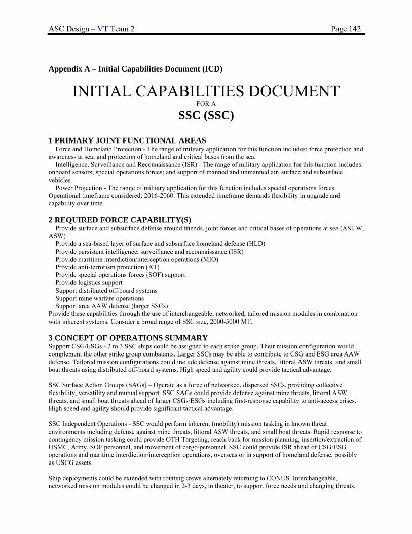
ASC Design – VT Team 2 Page 142
Appendix A – Initial Capabilities Document (ICD)
INITIAL CAPABILITIES DOCUMENT FOR A
SSC (SSC)
1 PRIMARY JOINT FUNCTIONAL AREAS � Force and Homeland Protection - The range of military application for this function includes: force protection and awareness at sea; and protection of homeland and critical bases from the sea. � Intelligence, Surveillance and Reconnaissance (ISR) - The range of military application for this function includes: onboard sensors; special operations forces; and support of manned and unmanned air, surface and subsurface vehicles. � Power Projection - The range of military application for this function includes special operations forces. Operational timeframe considered: 2016-2060. This extended timeframe demands flexibility in upgrade and capability over time. 2 REQUIRED FORCE CAPABILITY(S) � Provide surface and subsurface defense around friends, joint forces and critical bases of operations at sea (ASUW, ASW) � Provide a sea-based layer of surface and subsurface homeland defense (HLD) � Provide persistent intelligence, surveillance and reconnaissance (ISR) � Provide maritime interdiction/interception operations (MIO) � Provide anti-terrorism protection (AT) � Provide special operations forces (SOF) support � Provide logistics support � Support distributed off-board systems � Support mine warfare operations � Support area AAW defense (larger SSCs) Provide these capabilities through the use of interchangeable, networked, tailored mission modules in combination with inherent systems. Consider a broad range of SSC size, 2000-5000 MT. 3 CONCEPT OF OPERATIONS SUMMARY Support CSG/ESGs - 2 to 3 SSC ships could be assigned to each strike group. Their mission configuration would complement the other strike group combatants. Larger SSCs may be able to contribute to CSG and ESG area AAW defense. Tailored mission configurations could include defense against mine threats, littoral ASW threats, and small boat threats using distributed off-board systems. High speed and agility could provide tactical advantage. SSC Surface Action Groups (SAGs) – Operate as a force of networked, dispersed SSCs, providing collective flexibility, versatility and mutual support. SSC SAGs could provide defense against mine threats, littoral ASW threats, and small boat threats ahead of larger CSGs/ESGs including first-response capability to anti-access crises. High speed and agility should provide significant tactical advantage. SSC Independent Operations - SSC would perform inherent (mobility) mission tasking in known threat environments including defense against mine threats, littoral ASW threats, and small boat threats. Rapid response to contingency mission tasking could provide OTH Targeting, reach-back for mission planning, insertion/extraction of USMC, Army, SOF personnel, and movement of cargo/personnel. SSC could provide ISR ahead of CSG/ESG operations and maritime interdiction/interception operations, overseas or in support of homeland defense, possibly as USCG assets. Ship deployments could be extended with rotating crews alternately returning to CONUS. Interchangeable, networked mission modules could be changed in 2-3 days, in theater, to support force needs and changing threats.

ASC Design – VT Team 2 Page 143
Some MSCs could be configured with more capable AAW sensors and weapons that could also be modular, but require extended availability for upgrade or change-out. Hull plugs, modular deckhouse and modular mast options should be considered for these MSC variants. They would be able to contribute significant area AAW support for ESGs or as part of CSGs. 4 CAPABILITY GAP(S) The overarching capability gap addressed by this ICD is to provide affordable SSC capabilities in sufficient numbers for worldwide coverage of strike group and independent platform requirements. Specific capability gaps and requirements include:
Priority Capability Description Threshold Systems or metric Goal Systems or metric 5 THREAT AND OPERATIONAL ENVIRONMENT Since many potentially unstable nations are located on or near geographically constrained (littoral) bodies of water, the tactical picture may be at smaller scales relative to open ocean warfare. Threats in such an environment include: (1) technologically advanced weapons - cruise missiles like the Silkworm and Exocet, land-launched attack aircraft, fast gunboats armed with guns and smaller missiles, and diesel-electric submarines; and (2) unsophisticated and inexpensive passive weapons – mines (surface, moored and bottom), chemical and biological weapons. Encounters may occur in shallow water which increases the difficulty of detecting and successfully prosecuting targets.The sea-based environment includes: � Open ocean (sea states 0 through 8) and littoral � Shallow and deep water � Noisy and reverberation-limited � Degraded radar picture � Crowded shipping � Dense contacts and threats with complicated targeting � Biological, chemical and nuclear weapons � All-Weather 6 FUNCTIONAL SOLUTION ANALYSIS SUMMARY a. Ideas for Non-Materiel Approaches (DOTMLPF Analysis) � Increased reliance on foreign SSC support (Japan, NATO, etc.) to meet the interests of the U.S. b. Ideas for Materiel Approaches � Design and build small, high speed surface combatants (LCS) with limited capability for dedicated CSG operations, no significant area AAW contribution beyond self defense, and very limited multi-mission capability.

ASC Design – VT Team 2 Page 144
� Do not consider building surface combatants smaller than 5000 MT. Satisfy all surface combatant requirements with MSCs. � Design and build a scalable modular family of new SSC ships, 2000-5000 MT, with capabilities sufficient to satisfy the full range of specified SSC capability gaps using interchangeable, networked mission modules, and with the option of more capable AAW sensors and weapons that could also be modular, but added in construction or in a major availability using a hull plug, modular deckhouse, or modular mast(s). These variants would be able to contribute significant area AAW support for ESGs or as part of CSGs. 7 FINAL RECOMMENDATIONS a. Non-material solutions are not consistent with national policy. b. LCS-1 and 2 as designed may not be affordable in required force numbers. Reconfiguration for area AAW capability would be difficult. They may be too small and not sufficiently robust for required open ocean transits and CSG operations. Their service life may also be inadequate. c. Satisfying the SSC requirement with all MSCs in necessary force numbers is not affordable. d. The option of a scalable modular family of new SSC ships, 2000-5000 MT, with capabilities sufficient to satisfy the full range of specified SSC capability gaps using interchangeable, networked mission modules, and with the option of more capable AAW sensors and weapons should be explored. The feasibility of limiting follow-ship acquisition cost to $300M ($FY2013) must be investigated with an absolute constraint of $400M. Compromises in speed and inherent multi-mission capabilities may have to be considered. Trade-offs should be made based on total ownership cost (including cost of upgrade), effectiveness (including flexibility) and risk. It is anticipated that 50 of these ships may be built with a required service life of 30 years.
ASC Design – VT Team 2 Page 145
Appendix B– Acquisition Decision Memorandum (ADM)
August 24, 2009 From: Virginia Tech Naval Acquisition Executive To: SSC Design Teams Subject: ACQUISITION DECISION MEMORANDUM FOR a SSC Ref: (a) Virginia Tech SSC Initial Capabilities Document (ICD), 14 August 2009 1. This memorandum authorizes concept exploration of a single material alternative proposed in Reference (a) to the Virginia Tech Naval Acquisition Board on 14 August 2007. Additional material and non-material alternatives supporting this mission may be authorized in the future. 2. Concept exploration is authorized for a scalable modular family of new SSC ships, 2000-5000 MT, with capabilities sufficient to satisfy the full range of specified SSC capability gaps using interchangeable, networked mission modules, and with the option of more capable AAW sensors and weapons. AAW sensors and weapons could also be modular, but would be added in construction as a SSC variant or in a major availability using a hull plug, modular deckhouse, or modular mast(s). These variants would be able to contribute significant area AAW support for ESGs or as part of CSGs. A full range of affordable options satisfying identified capability gaps from threshold to goal should be considered. Affordability is a critical issue in order to enable sufficient force numbers to satisfy world-wide commitments consistent with national defense policy. Rising acquisition, manning, logistics support, maintenance and energy costs must be addressed with a comprehensive plan including the application of new technologies, automation, modularity, and a necessary rational compromise of inherent multi-mission capabilities. 3. The feasibility of limiting follow-ship acquisition cost to $300M ($FY2013) must be investigated with an absolute constraint of $400M. Compromises in speed and inherent multi-mission capabilities may have to be considered to achieve these cost goals and constraints. Trade-offs should be made based on total ownership cost (including cost of upgrade), effectiveness (including flexibility) and risk. It is anticipated that 50 of these ships may be built with IOC in 2016, and with a required service life of 30 years. A.J. Brown VT Acquisition Executive

ASC Design – VT Team 2 Page 146
Appendix C– Capabilities Development Document (CDD)
UNCLASSIFIED
CAPABILITY DEVELOPMENT DOCUMENT FOR
Large - SSC (SSC Large) VT Team 5
1 Capability Discussion The Initial Capabilities Document (ICD) for this CDD was issued by the Virginia Tech
Acquisition Authority on 14 August 2009. The overarching capability gap addressed by this ICD is to provide affordable, SSC capabilities in large numbers in order to accomplish worldwide coverage of strike group and independent platform requirements. To meet this overarching capability gap, the SSC must be capable of providing the following force capabilities:
1. Provide surface and subsurface defense around allies, joint forces, and critical bases of operation at sea (ASW, ASUW)
2. Provide a sea-based layer of surface and subsurface homeland defense (HLD) 3. Provide persistent intelligence, surveillance, and reconnaissance (ISR) 4. Provide maritime interdiction/interception operations (MIO) 5. Provide anti-terrorism protection (AT) 6. Provide special operations forces (SOF) support 7. Provide logistics support 8. Provide distributed off-board systems 9. Provide mine warfare operations 10. Support area AAW defense
Specific capability gaps and requirements as outlined in the ICD are listed below:

ASC Design – VT Team 2 Page 147
In order to fill all of the capability gaps in the ICD, the SSC is designed to accommodate interchangeable, networked mission modules. In order to satisfy requirements for AAW area defense in support of CSG’s and ESG’s, the large SSC must have more capable AAW sensors and weapons. According the the Acquisition Decision Memorandum (ADM) published on 24 August 2009, the AAW sensors and weapons on the large SSC could be modular, but would be added during construction or during a major availability using a hull plug, modular deckhouse, or modular mast.
2 Analysis Summary An Acquisition Decision Memorandum issued on 24 August 2009 by the Virginia Tech Acquisition Authority
directed Concept Exploration and Analysis of Alternatives (AoA) for a scalable, modular family of new SSC ships with an emphasis on providing a full range of affordable options to meet sufficient force numbers to satisfy worldwide commitments. Required core capabilities are AAW (SSC Large), force and homeland protection, intelligence, ISR, and power projection. Affordability is critical, and to provide sufficient numbers of SSC to meet worldwide commitments, the SSC must have the following attributes:
1. The platforms must be highly producible, maintainable and upgradable through significant modularization. 2. The time from concept to delivery must be minimized and systems must have commonality with other
platforms within the fleet. 3. New technologies and automation must be implemented. 4. The new ship must have minimum manning.
In addition, the concept exploration had to include a necessary rational compromise of inherent multi-mission
capabilities. Concept Exploration was conducted from 1 September 2009 through 11 December 2009. A Concept Design and
Requirements Review was conducted on 04 February 2009. This CDD presents the baseline requirements approved in the review.
Available technologies and concepts necessary to provide required functional capabilities were identified and defined in terms of performance, cost, risk and ship impact (weight, area, volume, power). Trade-off studies were performed using technology and concept design parameters to select trade-off options in a multi-objective genetic optimization (MOGO) for the total ship design. The result of this MOGO was a non-dominated frontier, Figure 1. This frontier includes designs with a wide range of risk and cost, each having the highest effectiveness for a given risk and cost. Preferred designs are often “knee in the curve” designs at the top of a large increase in effectiveness for a given cost and risk, or designs at high and low extremes. The design selected for Virginia Tech Team 5, and specified in this CDD, is a low-cost and low-risk design chosen from Figure 1. Selection of a point on the non-dominated frontier specifies requirements, technologies and the baseline design.
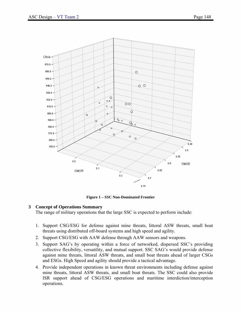
ASC Design – VT Team 2 Page 148
Figure 1 – SSC Non-Dominated Frontier
3 Concept of Operations Summary The range of military operations that the large SSC is expected to perform include:
1. Support CSG/ESG for defense against mine threats, littoral ASW threats, small boat threats using distributed off-board systems and high speed and agility.
2. Support CSG/ESG with AAW defense through AAW sensors and weapons.
3. Support SAG’s by operating within a force of networked, dispersed SSC’s providing collective flexibility, versatility, and mutual support. SSC SAG’s would provide defense against mine threats, littoral ASW threats, and small boat threats ahead of larger CSGs and ESGs. High Speed and agility should provide a tactical advantage.
4. Provide independent operations in known threat environments including defense against mine threats, littoral ASW threats, and small boat threats. The SSC could also provide ISR support ahead of CSG/ESG operations and maritime interdiction/interception operations.

ASC Design – VT Team 2 Page 149
SSC deployments could be extended with rotating crews, and this will result in longer periods between availabilities. In order to support the various capability gaps outlined in the ICD, the SSC will need to be equipped to handle interchangeable, networked mission modules. These modules could be changed in 2-3 days in theater.
The large SSC will be equipped with modular AAW capable sensors and weapons. These will be modular due to the extended operational timeframe considered (2016-2060). This extended time frame requires the flexibility to upgrade weapons and sensors over time. AAW capable sensor and weapons upgrades will require extended availability periods.
The range of military operations outlined above must be achieved with sufficient numbers of ships for worldwide and persistent coverage of all potential areas of conflict, vulnerability or interest.
Potential strengths of the large SSC are that it has the flexibility to satisfy a full range of specified capability gaps outlined in the ICD using interchangeable, networked modular mission modules. Most of these mission modules can be interchanged within 2-3 in theater, and this ability enables the SSC to provide a large range of military operations.
Potential limitations of a large SSC is that it not a true multi-mission ship. Individual SSCs carry a different module that enables it to perform specific missions, but it is not a large enough platform to enable it to fulfill all of the capability gaps outlined in the ICD at any given moment. The SSC has to have its mission modules swapped in theater or during an availability, and might not be capable meeting a given operational capability gap at any given time. Multiple SSCs with varying mission modules would be needed to support an ESG or CSG and provide the range of functions and capabilities outlined above. The SSC also does not have Ballistic Missile Defense (BMD) capability. Independent ballistic missile defense capability is an important operational capability outlined in the 2010 Quadrennial Defense Review (QDR), and the SSC is not a large enough platform to support large S-Band Radars.
Naval forces must also be able to support non-combatant and maritime interdiction operations in conjunction with national directives. They must be flexible enough to support peacetime missions yet be able to provide instant wartime response should a crisis escalate. The large SSC will provide an affordable solution that will meet many of the capability gaps outlined in the ICD.
4 Threat Summary Because many unstable nations are located near geographically constrained bodies of water,
the SSC must have the capability to engage an adversary in the littoral combat space. It must be small, fast, and agile enough to operate where large surface combatants cannot. The expected threats in a littoral environment include:
1. Technologically advanced weapons like the Silkworm and Exocet missiles, land-launched attack aircraft, small fast attack boats with guns and smaller missiles, and diesel-electric submarines.
2. Unsophisticated and inexpensive weapons like underwater mines (surface, moored, and bottom), and chemical and biological weapons.
The SSC will experience the following sea-based environments:
1. Open Water seaways (sea state 0 -8), and shallow water (littoral) maneuvering.
ASC Design – VT Team 2 Page 150
2. A degraded radar picture
3. Noise and reverberation
4. Crowded Shipping
5. Underwater explosions
6. Chemical, Biological, and Radiological (CBR) Environments
7. Dense contacts and threats with complicated targeting

ASC Design – VT Team 2 Page 151
5 System Capabilities and Characteristics Required for the Current Development Increment
Key Performance Parameter (KPP)
Development Threshold or Requirement
AAW ICMS, MK XII AIMS IFF, COMBAT DF, 2X-MK 137 LCHRs, AIEWS ADVANCED SEW SYSTEM, AN/SPY-1E MFR, GLYCOL WATER COOLING SYSTEM FOR SPY
ASUW IRST, AN/SPS-73, Small Arms Ammo, 2x50-cal MGs, Small Arms Locker, DORNA EO/IR Fire Control, 57 mm MK 3, 57mm stowage, 57mm ammo in gun mount(120), 57mm ammo magazie (880), 1x7m RHIB,
ASW SQQ-89 Underwater Fire Control, AN/SLQ-25A (NIXIE) and AN/SLR-24I (TRIPWIRE), 2x Mk 32 SVTT on deck, NDS 3070 Vanguard mine sonar, SQS-56 sonar and dome
CCCC CTSCE, Comms Suite Level A, Cooperative Engagement Capability
LAMPS Dual SH-60 helo and hangar, fuel, support LAMPS (modules, RAST, Aviation Magz,
GMLS 2x MK41 VLS 16-cell W/3 Tomahawk + 10 SM-2 + 3 VLASROC, MK 41 control System, VLS armor, VLS magazine dewatering system
LCS Modules 1.5 times LCS mission package not including LAMPS
Hull Steel, Flared Monohull
Power and Propulsion 2 shaft CODAG, 2xLM2500+ 2xCAT3616
SS Power 4 x CAT3508B
Endurance Range (nm) 4621 nm
Sustained Speed (knots) 32 knots
Endurance Speed (knots) 20 knots
Stores Duration (days) 70 days
Collective Protection System Full
Crew Size 65
Length (m) 121.8 m
Beam (m) 15.1 m
Design Draft (m) 5 m
Full Load Delivery KG (m) 5.3
Full Load Delivery Displacement (MT)
5200 MT
Vulnerability (Hull Material) Steel
Ballast/fuel system Clean, separate ballast tanks
Degaussing System Yes
McCreight Seakeeping Index 15.5
KG margin (m) 5.5 m
Propulsion power margin (design) 10%
Propulsion power margin (fouling and seastate) 25% (0.8 MCR)
Electrical margins 5%
Net Weight margin (design and service) 10%
6 Program Affordability
According to the ADM the average follow-ship acquisition cost shall not exceed $300 M ($FY2013) with an absolute constraint of $400 M. It is expected that 50 ships of this type will be built with IOC in 2016 with a required service life of 30 years.

ASC Design – VT Team 2 Page 152
Appendix D – Machinery Equipment List (MEL)

ASC Design – VT Team 2 Page 153

ASC Design – VT Team 2 Page 154
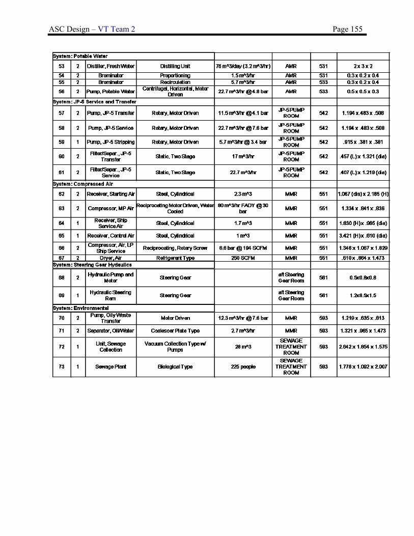
ASC Design – VT Team 2 Page 155

ASC Design – VT Team 2 Page 156
Appendix E - Weights and Centers
SWBS COMPONENT WT-MT VCG-m Moment LCG-m Moment
FULL LOAD WEIGHT + MARGIN 5039.58 5.78 29145.50 75.43 380159.63 MINOP WEIGHT AND MARGIN 4509.87 6.11 27541.78 76.83 346501.11 LIGHTSHIP WEIGHT + MARGIN 4190.12 6.35 26600.27 78.30 328076.92 LIGHTSHIP WEIGHT 3809.20 6.35 24182.06 78.30 298251.75 MARGIN 380.92 6.35 2418.21 78.30 29825.17
100 HULL STRUCTURES 1695.10 5.98 10136.98 63.47 107593.69 BARE HULL 0.00 0.00 0.00 0.00 0.00
110 SHELL + SUPPORTS 475.60 2.51 1193.76 57.56 27375.54 120 HULL STRUCTURAL BULKHDS 86.40 5.64 487.30 56.96 4921.34 130 HULL DECKS 321.50 7.89 2536.64 61.68 19830.12 140 HULL PLATFORMS/FLATS 2.10 3.60 7.56 65.93 138.45 150 DECK HOUSE STRUCTURE 237.00 14.64 3469.68 62.38 14784.06 160 SPECIAL STRUCTURES 170.70 4.24 723.77 82.03 14002.52 170 MASTS+KINGPOSTS+SERV PLATFORM 1.00 27.00 27.00 63.92 63.92 180 FOUNDATIONS 312.00 3.77 1176.24 66.80 20841.60 190 SPECIAL PURPOSE SYSTEMS 88.80 5.80 515.04 63.47 5636.14
200 PROPULSION PLANT 840.80 3.21 4025.60 77.05 112885.38
BASIC MACHINERY 0.00 6.58 0.00 120.00 0.00 230 PROPULSION UNITS 140.10 4.32 605.23 64.00 8966.40 233 DIESEL ENGINES 81.30 4.53 368.29 64.00 5203.20 234 GAS TURBINES 58.80 4.02 236.38 64.00 3763.20 235 ELECTRIC PROPULSION 0.00 0.00 240 TRANSMISSION+PROPULSOR SYSTEMS 480.20 1.50 720.30 83.90 40288.78 241 REDUCTION GEARS 227.40 2.16 491.18 64.00 14553.60 242 CLUTCHES + COUPLINGS 0.00 0.00 243 SHAFTING 116.70 0.92 107.36 89.25 10415.48 244 SHAFT BEARINGS 44.80 1.26 56.45 86.69 3883.71 245 PROPULSORS 91.30 0.69 63.00 116.00 10590.80 250 SUPPORT SYSTEMS, UPTAKES 115.10 8.64 994.46 69.75 8028.23 260 PROPUL SUP SYS- FUEL, LUBE OIL 54.40 3.73 202.91 64.79 3524.58 290 SPECIAL PURPOSE SYSTEMS 51.00 3.53 180.03 71.91 3667.41
300 ELECTRIC PLANT, GENERAL 366.80 7.31 3279.19 64.78 23762.34 310 ELECTRIC POWER GENERATION 125.20 4.90 613.48 63.14 7905.13
BASIC MACHINERY 0.00 9.32 0.00 105.00 0.00 311 SHIP SERVICE POWER GENERATION 92.20 3.58 330.08 40.00 3688.00 312 EMERGENCY GENERATORS 0.00 0.00 314 POWER CONVERSION EQUIPMENT 30.00 8.81 264.30 38.00 1140.00 320 POWER DISTRIBUTION SYS 145.40 9.31 1353.67 40.00 5816.00 330 LIGHTING SYSTEM 30.30 11.00 333.30 64.04 1940.41 340 POWER GENERATION SUPPORT SYS 42.30 6.78 286.79 40.00 1692.00 390 SPECIAL PURPOSE SYS 24.70 3.95 97.57 64.00 1580.80
400 COMMAND+SURVEILLANCE 168.00 8.02 1346.71 46.45 7803.34

ASC Design – VT Team 2 Page 157
PAYLOAD 0.00 20.96 0.00 95.00 0.00 CABLING 0.00 11.98 0.00 103.00 0.00 MISC 0.00 11.98 0.00 105.00 0.00
410 COMMAND+CONTROL SYS 9.90 7.85 77.72 56.00 554.40 420 NAVIGATION SYS 8.50 22.54 191.59 49.73 422.71 430 INTERIOR COMMUNICATIONS 26.70 7.53 201.05 53.45 1427.12 440 EXTERIOR COMMUNICATIONS 23.10 7.85 181.34 60.88 1406.33 450 SURF SURVEILLANCE SYS (RADAR) 18.90 16.00 302.40 60.88 1150.63 460 UNDERWATER SURVEILLANCE SYSTEMS 19.50 -0.35 -6.83 8.00 156.00 470 COUNTERMEASURES 25.50 6.51 166.01 54.13 1380.32 480 FIRE CONTROL SYS 5.30 12.06 63.92 60.88 322.66 490 SPECIAL PURPOSE SYS 30.60 5.54 169.52 32.13 983.18
500 AUXILIARY SYSTEMS, GENERAL 600.60 7.74 4648.92 66.04 39661.97
WAUX 0.00 10.65 0.00 100.00 0.00 PAYLOAD 0.00 0.00 0.00
510 CLIMATE CONTROL 135.30 10.57 1430.12 66.97 9061.04 CPS 0.00 17.00 0.00 100.00 0.00
520 SEA WATER SYSTEMS 81.40 6.12 498.17 66.97 5451.36 530 FRESH WATER SYSTEMS 40.10 7.41 297.14 66.97 2685.50 540 FUELS/LUBRICANTS,HANDLING+STORAGE 30.10 3.66 110.17 66.97 2015.80 550 AIR,GAS+MISC FLUID SYSTEM 82.30 7.88 648.52 66.97 5511.63 560 SHIP CNTL SYS 44.90 3.63 162.99 119.78 5378.12 570 UNDERWAY REPLENISHMENT SYSTEMS 40.20 6.38 256.48 66.97 2692.19 581 ANCHOR HANDLING+STOWAGE SYSTEMS 43.90 7.56 331.88 7.00 307.30 582 MOORING+TOWING SYSTEMS 12.60 9.11 114.79 66.97 843.82 583 BOATS,HANDLING+STOWAGE SYSTEMS 5.20 6.00 31.20 119.00 618.80 585 AIRCRAFT WEAPONS ELEVATORS 0.00 7.00 0.00 120.00 0.00 586 AIRCRAFT RECOVERY SUPPORT SYS 0.00 26.00 0.00 150.00 0.00 587 AIRCRAFT LAUNCH SUPPORT SYSTEM 0.00 19.00 0.00 60.00 0.00 588 AIRCRAFT HANDLING, SUPPORT 32.40 13.00 421.20 82.00 2656.80 589 0.00 17.00 0.00 100.00 0.00 593 ENVIRONMENTAL POLLUTION CNTL SYS 9.90 3.70 36.63 66.97 663.00 598 AUX SYSTEMS OPERATING FLUIDS 42.30 7.32 309.64 42.00 1776.60
600 OUTFIT+FURNISHING,GENERAL 33.20 2.71 90.04 75.24 2498.02 610 SHIP FITTINGS 11.80 0.92 10.86 75.68 893.02 640 LIVING SPACES 21.40 3.70 79.18 75.00 1605.00
700 ARMAMENT 104.70 6.25 654.63 38.65 4047.01 710 GUNS+AMMUNITION 9.50 11.35 107.83 60.88 578.36 720 MISSLES+ROCKETS 84.70 5.39 456.53 34.00 2879.80 750 TORPEDOES 2.70 12.00 32.40 60.88 164.38 760 SMALL ARMS+PYROTECHNICS 7.80 7.42 57.88 54.42 424.48
FULL LOAD CONDITION
F00 LOADS 849.46 3.00 2545.24 61.31 52082.71 F10 SHIPS FORCE 9.10 6.81 61.97 57.23 520.79
F20* MISSION RELATED EXPENDABLES 175.50 7.28 1277.64 60.88 10684.44 F21 SHIP AMMUNITION 11.30 7.87 88.93 50.00 565.00 F22 ORD DEL SYS AMMO 11.20 3.35 37.52 60.88 681.86
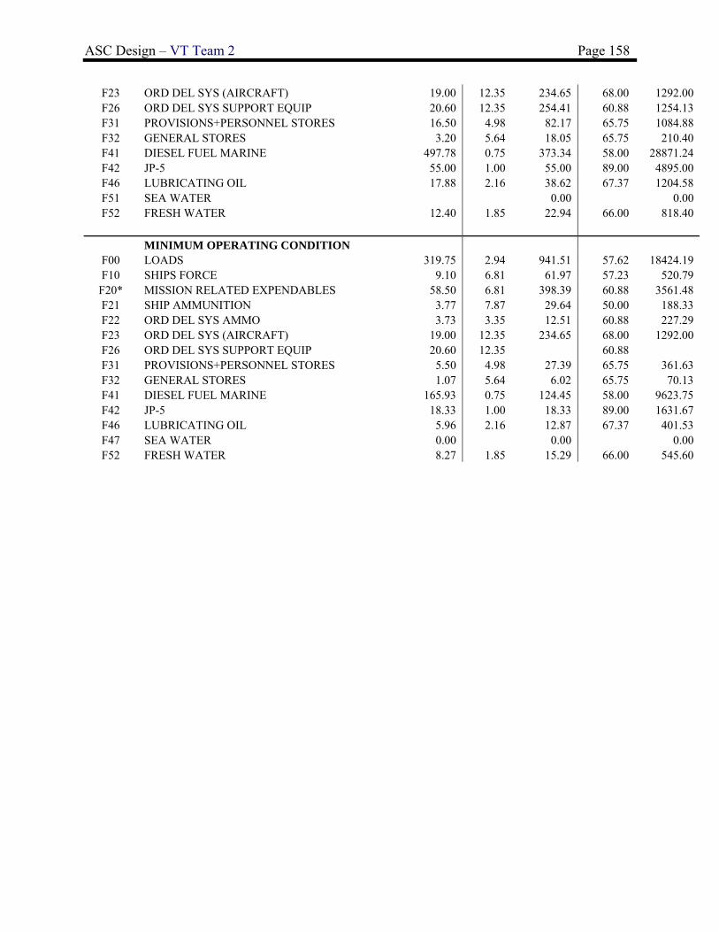
ASC Design – VT Team 2 Page 158
F23 ORD DEL SYS (AIRCRAFT) 19.00 12.35 234.65 68.00 1292.00 F26 ORD DEL SYS SUPPORT EQUIP 20.60 12.35 254.41 60.88 1254.13 F31 PROVISIONS+PERSONNEL STORES 16.50 4.98 82.17 65.75 1084.88 F32 GENERAL STORES 3.20 5.64 18.05 65.75 210.40 F41 DIESEL FUEL MARINE 497.78 0.75 373.34 58.00 28871.24 F42 JP-5 55.00 1.00 55.00 89.00 4895.00 F46 LUBRICATING OIL 17.88 2.16 38.62 67.37 1204.58 F51 SEA WATER 0.00 0.00 F52 FRESH WATER 12.40 1.85 22.94 66.00 818.40
MINIMUM OPERATING CONDITION
F00 LOADS 319.75 2.94 941.51 57.62 18424.19 F10 SHIPS FORCE 9.10 6.81 61.97 57.23 520.79
F20* MISSION RELATED EXPENDABLES 58.50 6.81 398.39 60.88 3561.48 F21 SHIP AMMUNITION 3.77 7.87 29.64 50.00 188.33 F22 ORD DEL SYS AMMO 3.73 3.35 12.51 60.88 227.29 F23 ORD DEL SYS (AIRCRAFT) 19.00 12.35 234.65 68.00 1292.00 F26 ORD DEL SYS SUPPORT EQUIP 20.60 12.35 60.88 F31 PROVISIONS+PERSONNEL STORES 5.50 4.98 27.39 65.75 361.63 F32 GENERAL STORES 1.07 5.64 6.02 65.75 70.13 F41 DIESEL FUEL MARINE 165.93 0.75 124.45 58.00 9623.75 F42 JP-5 18.33 1.00 18.33 89.00 1631.67 F46 LUBRICATING OIL 5.96 2.16 12.87 67.37 401.53 F47 SEA WATER 0.00 0.00 0.00 F52 FRESH WATER 8.27 1.85 15.29 66.00 545.60

ASC Design – VT Team 2 Page 159
Appendix F – SSCS Space Summary
SSCS GROUP
(ass
et)
VO
LU
ME
(m
3)
(act
ual)
VO
LU
ME
(m
3)
(ass
et)
AR
EA
(m
2)
(act
ual)
AR
EA
(m
2)
Typical Associated Spaces
TOTAL AVAILABLE 711 6714.676
TOTAL REQUIRED 1148 3623
1 MISSION SUPPORT 72.4 46 369.1 1510.219
1.1 COMMAND,COMMUNICATION+SURV 0 0 117.7 586.5796
1.11 EXTERIOR COMMUNICATIONS 0 0 5.9 43.7
1.111 RADIO 43.7 Communications
1.113 VISUAL COM 5.9 0 Signal Bridge
1.12 SURVEILLANCE SYS 0 0 23.3 95.2975
1.121 SURFACE SURV (RADAR) 57.34 Electronics Spaces, Radar and Radar Cooling Rooms
1.122 UNDERWATER SURV (SONAR) 23.3 37.9575 Sonar Rooms (2 or 3), TACTASS Winch Room
1.13 COMMAND+CONTROL 0 0 46.7 89.49
1.131 COMBAT INFO CENTER 89.49 CIC
1.132 CONNING STATIONS 0 0 46.7 0 bridgewings or aft of deckhouse
1.1321 PILOT HOUSE 39.7 43.64 Pilot House
1.1322 CHART ROOM 7 16.16 Chart Room
1.14 COUNTERMEASURES 0 0 0 294.71
1.141 ELECTRONIC 289.22 deck sensors
1.142 TORPEDO 5.49 Nixie Winch Room
1.143 MISSILE 0 deck launchers
1.15 INTERIOR COMMUNICATIONS 41.8 51.9 IC Room
1.16 ENVIORNMENTAL CNTL SUP SYS 11.4821
Environmental Protection Equipment Room, Environmental Waste Stowage, Sewage Treatment Room, Collection Holding and Transfer (CHT) Room and Tank
1.2 WEAPONS 0 0 0 340.286
1.21 GUNS 0 0 0 89.9
1.214 AMMUNITION STOWAGE 89.9 Gun Magazines
1.22 MISSILES 183.386 Vertical Missile Launchers (VLS)
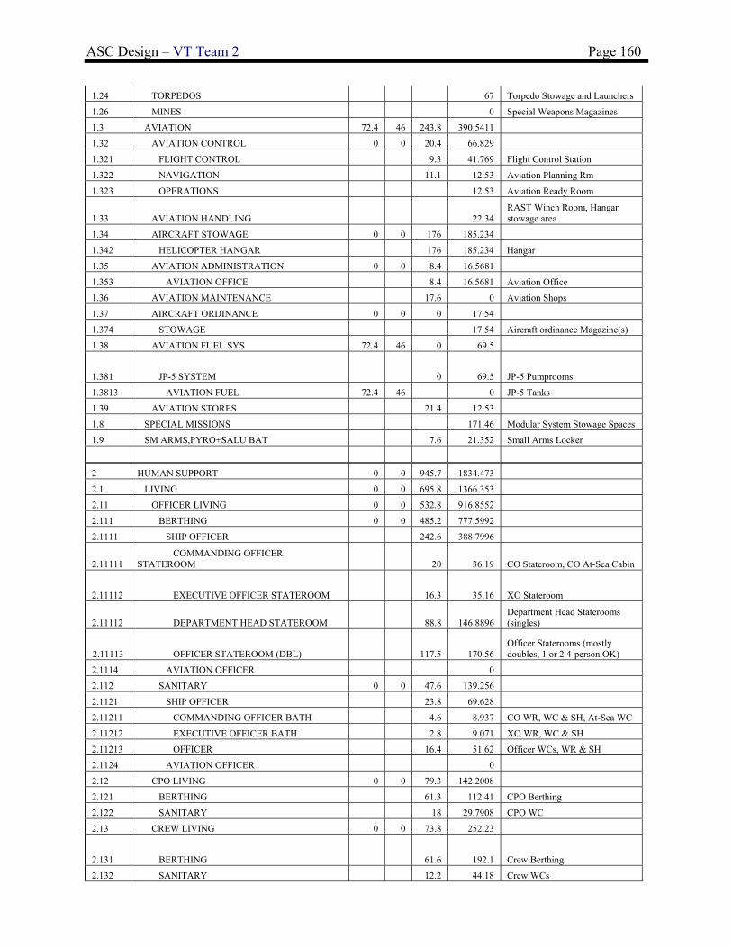
ASC Design – VT Team 2 Page 160
1.24 TORPEDOS 67 Torpedo Stowage and Launchers
1.26 MINES 0 Special Weapons Magazines
1.3 AVIATION 72.4 46 243.8 390.5411
1.32 AVIATION CONTROL 0 0 20.4 66.829
1.321 FLIGHT CONTROL 9.3 41.769 Flight Control Station
1.322 NAVIGATION 11.1 12.53 Aviation Planning Rm
1.323 OPERATIONS 12.53 Aviation Ready Room
1.33 AVIATION HANDLING 22.34 RAST Winch Room, Hangar stowage area
1.34 AIRCRAFT STOWAGE 0 0 176 185.234
1.342 HELICOPTER HANGAR 176 185.234 Hangar
1.35 AVIATION ADMINISTRATION 0 0 8.4 16.5681
1.353 AVIATION OFFICE 8.4 16.5681 Aviation Office
1.36 AVIATION MAINTENANCE 17.6 0 Aviation Shops
1.37 AIRCRAFT ORDINANCE 0 0 0 17.54
1.374 STOWAGE 17.54 Aircraft ordinance Magazine(s)
1.38 AVIATION FUEL SYS 72.4 46 0 69.5
1.381 JP-5 SYSTEM 0 69.5 JP-5 Pumprooms
1.3813 AVIATION FUEL 72.4 46 0 JP-5 Tanks
1.39 AVIATION STORES 21.4 12.53
1.8 SPECIAL MISSIONS 171.46 Modular System Stowage Spaces
1.9 SM ARMS,PYRO+SALU BAT 7.6 21.352 Small Arms Locker
2 HUMAN SUPPORT 0 0 945.7 1834.473
2.1 LIVING 0 0 695.8 1366.353
2.11 OFFICER LIVING 0 0 532.8 916.8552
2.111 BERTHING 0 0 485.2 777.5992
2.1111 SHIP OFFICER 242.6 388.7996
2.11111 COMMANDING OFFICER STATEROOM 20 36.19 CO Stateroom, CO At-Sea Cabin
2.11112 EXECUTIVE OFFICER STATEROOM 16.3 35.16 XO Stateroom
2.11112 DEPARTMENT HEAD STATEROOM 88.8 146.8896 Department Head Staterooms (singles)
2.11113 OFFICER STATEROOM (DBL) 117.5 170.56 Officer Staterooms (mostly doubles, 1 or 2 4-person OK)
2.1114 AVIATION OFFICER 0
2.112 SANITARY 0 0 47.6 139.256
2.1121 SHIP OFFICER 23.8 69.628
2.11211 COMMANDING OFFICER BATH 4.6 8.937 CO WR, WC & SH, At-Sea WC
2.11212 EXECUTIVE OFFICER BATH 2.8 9.071 XO WR, WC & SH
2.11213 OFFICER 16.4 51.62 Officer WCs, WR & SH
2.1124 AVIATION OFFICER 0
2.12 CPO LIVING 0 0 79.3 142.2008
2.121 BERTHING 61.3 112.41 CPO Berthing
2.122 SANITARY 18 29.7908 CPO WC
2.13 CREW LIVING 0 0 73.8 252.23
2.131 BERTHING 61.6 192.1 Crew Berthing
2.132 SANITARY 12.2 44.18 Crew WCs

ASC Design – VT Team 2 Page 161
2.133 RECREATION 15.95 Crew Recreation
2.14 GENERAL SANITARY FACILITIES 0 0 2.3 11.59
2.142 BRIDGE WASHRM & WC 2.3 11.59 Bridge WC
2.15 SHIP RECREATION FAC 4.3 15.95 Crew Recreation Room
2.16 TRAINING 3.3 27.5268 Crew Training
2.2 COMMISSARY 0 0 194.1 350.4896
2.21 FOOD SERVICE 0 0 117.1 207.57
2.211 WARDROOM MESSRM & LOUNGE 51.1 74.97 Wardroom Mess
2.212 CPO MESSROOM AND LOUNGE 51.1 44.28 CPO Mess and Lounge
2.213 CREW MESSROOM 14.9 88.32 Crew Mess
2.22 COMMISSARY SERVICE SPACES 0 0 41.6 67.5442
2.222 GALLEY 0 0 24.9 51.1238
2.2222 WARD ROOM GALLEY 9.8 20.087 WR Galley
2.2224 CREW GALLEY 15.1 31.0368 Crew Gally
2.223 WARDROOM PANTRY 7.4 9.32 WR Pantry
2.224 SCULLERY 9.3 7.1004 Scullery
2.23 FOOD STORAGE+ISSUE 0 0 35.4 75.3754
2.231 CHILL PROVISIONS 11.6 24.99 Chill Box
2.232 FROZEN PROVISIONS 7.6 24.7754 Freeze Box
2.233 DRY PROVISIONS 16.2 25.61 Dry Provision SR
2.3 MEDICAL+DENTAL 1.4 21.3331 Sick Bay
2.4 GENERAL SERVICES 0 0 19 22.678
2.41 SHIP STORE FACILITIES 6.9 0 Ship Store
2.42 LAUNDRY FACILITIES 12.1 22.678 Laundry
2.44 BARBER SERVICE 0 Barber Shop
2.46 POSTAL SERVICE 0 Ship Post office
2.47 BRIG 0 Brig
2.5 PERSONNEL STORES 0 0 7.3 22.5
2.51 BAGGAGE STOREROOMS 6.7 0 Officer baggage storeroom
2.55 FOUL WEATHER GEAR 0.6 22.5 Bosn Stores, Foul Weather Gear Locker
2.6 CBR PROTECTION 0 0 26.2 40.1792
2.61 CBR DECON STATIONS 17.262 Decon Stations
2.62 CBR DEFENSE EQUIPMENT 10.7 13.19 CBR stowage
2.63 CPS AIRLOCKS 15.5 9.7272 Airlocks
2.7 LIFESAVING EQUIPMENT 1.9 10.94 life jacket stowage
3 SHIP SUPPORT 1076 665 1472 1235.01
3.1 SHIP CNTL SYS (STEERING) 0 0 59.1 47.71
3.11 STEERING GEAR 59.1 47.71 After Steering
3.12 ROLL STABILIZATION 0
3.15 STEERING CONTROL 0
3.2 DAMAGE CONTROL 0 0 60.3 95.7364
3.21 DAMAGE CNTRL CENTRAL 15.6284 DC Central
3.22 REPAIR STATIONS 37.3 61.0157 Repair Lockers
3.25 FIRE FIGHTING 23 19.0923 Fire Fighting Stations
3.3 SHIP ADMINISTRATION 0 0 37.5 105.5238
3.301 GENERAL SHIP 4.5 16.2529 Ship's Office
3.302 EXECUTIVE DEPT 10.3 16.86 Ship's Office
3.303 ENGINEERING DEPT 6.3 13.9569 Engineering Office

ASC Design – VT Team 2 Page 162
3.304 SUPPLY DEPT 5.2 15.584 Supply Office
3.305 DECK DEPT 2.7 14.11 Deck Department Office
3.306 OPERATIONS DEPT 8.5 16.86 Operations Department Office
3.307 WEAPONS DEPT 11.9 Weapons Department Office
3.5 DECK AUXILIARIES 0 0 53.1 108.277
3.51 ANCHOR HANDLING 31.4 60.56 Anchor Windlass Room and Chain Lockers
3.52 LINE HANDLING 0 Line Handling Stations / Capstans
3.53 TRANSFER-AT-SEA 21.7 0 Unrep Stations
3.54 SHIP BOATS STOWAGE 47.717 Boat davits or boat ramp aft
3.6 SHIP MAINTENANCE 0 0 88.1 100.8
3.61 ENGINEERING DEPT 0 0 65.2 60.48
3.611 AUX (FILTER CLEANING) 9.8 20.16 Filter Cleaning Shop
3.612 ELECTRICAL 23 20.16 Electrical Shop
3.613 MECH (GENERAL WK SHOP) 32.4 20.16 Work Shop
3.62 OPERATIONS DEPT (ELECT SHOP) 17.5 20.16 Electronics Repair Shop
3.63 WEAPONS DEPT (ORDINANCE SHOP) 5.4 20.16 Ordnance Shop
3.64 DECK DEPT (CARPENTER SHOP) 0 Carpenter Shop
3.7 STOWAGE 0 0 265.6 127.4724
3.71 SUPPLY DEPT 0 0 183.4 93.9604
3.711 HAZARDOUS MATL (FLAM LIQ) 24 0 Flamable Liquid/Paint Storeroom
3.713 GEN USE CONSUM+REPAIR PART 153.3 46.5778 General Storerooms
3.714 SHIP STORE STORES 6.1 47.3826 General Storerooms
3.72 ENGINEERING DEPT 5 0 Engineering Storage
3.73 OPERATIONS DEPT 7 0 Operations Storage
3.74 BOATSWAIN STORES 62.3 3.728
3.75 WEAPONS DEPT 4.5 29.784 Weapons Dept Stowage
3.78 CLEANING GEAR STOWAGE 3.4 0 Cleaning Gear Lockers
3.8 ACCESS 0 0 902.1 602
3.82 INTERIOR 0 0 902.1 602
3.821 NORMAL ACCESS 891.4 600 Passageways
3.822 ESCAPE ACCESS 10.7 2 Escape trunks
3.9 TANKS 1076 665 6.4 47.49
3.91 SHIP PROP SYS TNKG 844.2 574 0 0
3.9111 ENDUR FUEL TANK (INCL SERVICE) 844.2 574 DFM Tanks and Service Tanks
3.914 FEEDWATER TNKG Feedwater Tanks
3.92 BALLAST TNKG 56 55 Ballast Tanks, Peak Tank
3.93 FRESH WATER TNKG 12.7 8 Fresh Water Tanks
3.94 POLLUTION CNTRL TNKG 28 28 6.4 47.49
3.941 SEWAGE TANKS 1.6 20.56 Sewage/Holding Tanks
3.942 OILY WASTE TANKS 28 28 4.8 26.93 Oily Waste Tanks

ASC Design – VT Team 2 Page 163
3.95 VOIDS 134.9 Voids
4 SHIP MACHINERY SYSTEM 0 0 836.4 2134.975
4.1 PROPULSION SYSTEM 543.3 814.4 MMRs, Motor Rooms
4.142
COMBUSTION AIR (INTAKE)
28.6 Intakes
4.143 EXHAUST 68.9 Exhaust
4.2 PROPULSOR & TRANSMISSION SYST 0 0 0 0
4.23 WATERJET ROOMS 0 WJ Rooms
4.23001 PROP SHAFT ALLEY 0 Shaft Alleys
4.3 AUX MACHINERY 0 0 293.1 1320.575 AMRs and MMRs
4.33 ELECTRICAL 0 0 75 1269.17
4.331 POWER GENERATION 70.5 1258 AMRs and MMRs
4.334 DEGAUSSING 4.5 11.1695 Degaussing Room
4.34 POLLUTION CONTROL SYSTEMS 5.7 12.3375
Environmental Protection Equipment Room, Environmental Waste Stowage, Sewage Treatment Room, Collection Holding and Transfer (CHT) Room and Tank
4.36 VENTILATION SYSTEMS 212.4 39.0684 Fan Rooms (8-12+)

ASC Design – VT Team 2 Page 164
Appendix G – Power and Propulsion Analysis