Embed Size (px)
Citation preview
March 2017
DESIGN REPORT ON
Geotechnical Investigation Preliminary Design of the Third Crossing of the Cataraqui River John Counter Boulevard to Gore Road Kingston, Ontario
Submitted to: J.L. Richards & Associates Ltd. 203 - 863 Princess Street Kingston, ON K7L 5N4 Report Number: 1541774/2000/0003-002 Distribution: 2 Copies - J.L. Richards & Associates Ltd. 1 Copy - Golder Associates Ltd.

Preliminary Geotechnical Investigation Third Crossing of the Cataraqui River
Table of Contents
1.0 Introduction 1
2.0 Description Of Project And Site 1
3.0 Discussion 2
3.1 Foundation Options 2
3.1.1 Shallow Foundations 2
3.1.1.1 Geotechnical Resistance 3
3.1.1.2 Resistance to Lateral Loads 4
3.1.2 Driven Steel H-Pile or Steel Pipe (Tube) Pile Foundations 4
3.1.2.1 Founding Elevations 4
3.1.2.2 Axial Geotechnical Resistance 6
3.1.2.3 Resistance to Lateral Loads 6
3.1.3 Caisson Foundations 9
3.1.3.1 Axial Geotechnical Resistance 9
3.1.3.2 Resistance to Lateral Loads 10
3.1.4 Pier Cap Construction 10
3.2 Seismic Design 10
3.2.1 Seismic Site Classification 10
3.2.2 Spectral Response Values and Seismic Performance Category 11
3.3 Approach Embankments 12
3.3.1 General Embankment Construction 13
3.3.2 Global Stability 14
3.3.3 Static Settlement 14
3.4 Design and Construction Considerations 15
3.4.1 Excavation and Temporary Protection Systems 15
3.4.2 Groundwater and Surface Water Control 15
3.5 Recommendations for Further Work in Detail Design 16
4.0 Closure 17
March 2017 Report No. 1541774/2000/0003-002 i
Preliminary Geotechnical Investigation Third Crossing of the Cataraqui River
Important Information and Limitations of This Report
Tables Table 1: Maximum Founding Elevations, Spread Footings on Bedrock 3
Table 2: Interpreted Design Pile Tip Elevations 5
Table 3: Factored Axial Geotechnical Resistances 6
Table 4: Soil Properties for Lateral Geotechnical Resistance of Deep Foundations 7
Table 5: Spectral Acceleration Values for Reference Ground Condition Site Class C 11
Table 6: Spectral Acceleration Values for Site Class B 12
Table 7: Spectral Acceleration Values for Site Class D 12
Figures Figure 1 – Key Plan
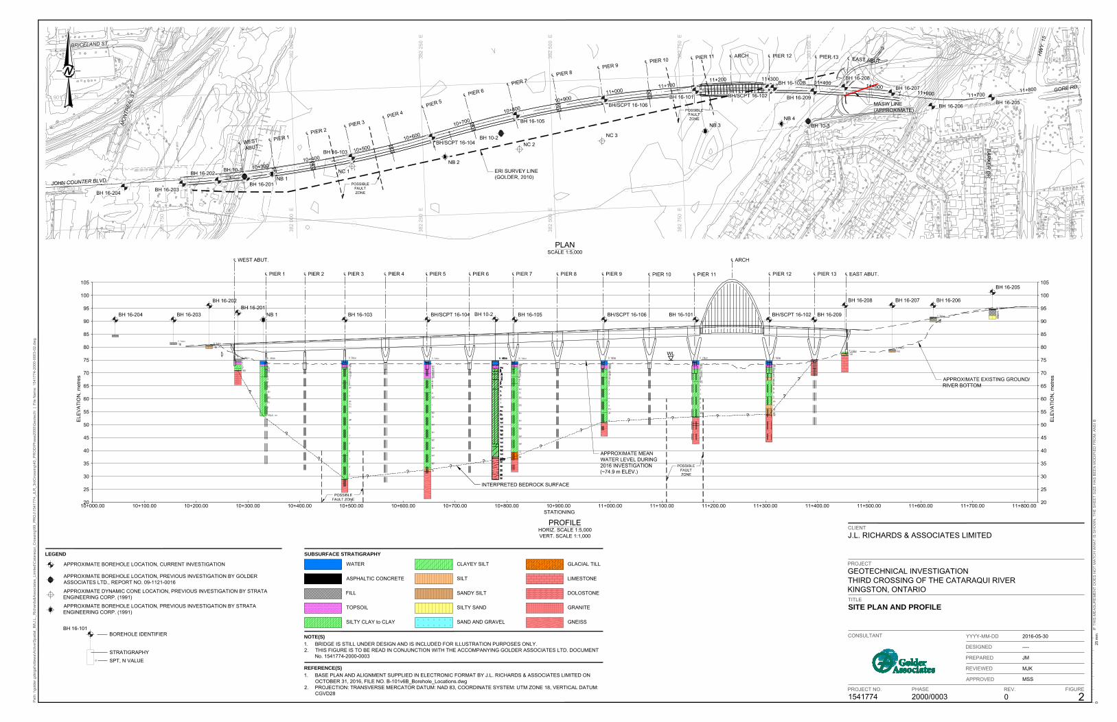
Figure 2 – Site Plan and Stratigraphic Profile
March 2017 Report No. 1541774/2000/0003-002 ii

Preliminary Geotechnical Investigation Third Crossing of the Cataraqui River
1.0 Introduction Golder Associates Ltd. (Golder) has been retained by J.L. Richards & Associates Ltd. (JLR) on behalf of the City of Kingston (City) to carry out multi-disciplinary subsurface investigations associated with the preliminary design of the proposed third crossing of the Cataraqui River in Kingston, Ontario (see Key Plan, Figure 1).
This report provides engineering guidelines and comments on the geotechnical design aspects of the preliminary design of the proposed bridge. The recommendations provided herein are based on interpretation of the factual data obtained from the boreholes advanced during the previous and current subsurface investigations. The discussion and recommendations presented are intended to provide the designers with sufficient information to assess the feasible foundation alternatives and to carry out the preliminary design of the proposed bridge crossing.
General descriptions of the subsurface conditions at the proposed west approach and abutment (John Counter Boulevard), the Cataraqui River Crossing, and the proposed east approach and abutment (near Gore Road) are provided under separate cover in the following report:
Factual Data Report prepared by Golder for J.L. Richards & Associates Ltd. titled “Preliminary Geotechnical Investigation, Third Crossing of the Cataraqui River, John Counter Boulevard to Gore Road, Kingston, Ontario” dated December 2016 (Golder Document No. 1541774/2000/0003-001).
This report should be read in conjunction with the above-noted Factual Data Report and the “Important Information and Limitations of This Report” which follows the text but forms an integral part of this document.
2.0 Description of Project and Site Preliminary design is being carried out for a third crossing of the Cataraqui River in Kingston, Ontario. The crossing is to be located between the existing Highway 401 bridge to the north and the LaSalle Causeway to the south (see Key Plan, Figure 1).
The following is known about the proposed third crossing of the Cataraqui River:
The crossing will consist of a two lane bridge to connect existing transportation infrastructure along John Counter Boulevard on the west bank of the river and Gore Road on the east bank of the river.
The proposed bridge will be a fourteen span bridge with a total length of about 1,200 metres.
The span lengths range from about 60 to 105 metres with a 150 metre long main span between Pier 11 and Pier 12 for clearance across the existing navigation channel.
The water depth of the Cataraqui River is generally relatively shallow (ranging from about 1.0 to 2.0 metres), except at the dredged navigable channel, where the water depth increases to about 5.0 metres.
March 2017 Report No. 1541774/2000/0003-002 1

Preliminary Geotechnical Investigation Third Crossing of the Cataraqui River
Previous subsurface investigations have been carried out at the site by Golder and others. The results of the previous investigations were presented in the following documents:
1) Technical Memorandum prepared by Golder Associates Ltd. for JLR, titled “Cataraqui River Crossing EA Study, Geotechnical and Geophysical Findings and Preliminary Guidelines” dated December 20, 2010 (Project Number 09-1121-0016).
2) Preliminary Report prepared by Strata Engineering Corp. for Totten Sims Hubicki Associates Ltd., titled “Preliminary Geotechnical Report, Cataraqui River Crossing, City of Kingston & Township of Pittsburgh” dated April 30, 1991 (Project Number E-90-034).
Based on the results of the previous and current investigations as well as published geologic mapping, the subsurface conditions within the third crossing alignment area are expected to generally consist of a limited overburden over shallow limestone bedrock on the shores of the Cataraqui River, and a thick deposit of sensitive silty clay overlying gneissic bedrock within the Cataraqui River channel. 3.0 Discussion This section of the report provides foundation design recommendations for the preliminary design of the proposed third crossing of the Cataraqui River. The recommendations are based on interpretation of the factual data obtained from the boreholes advanced during the previous and current subsurface investigations.
It is understood that the bridge is to be designed in accordance with the current Canadian Highway Bridge Design Code CAN/CSA-S6-14 (CHBDC). In accordance with Section 4.4.2 of the CHBDC, it is further understood that the proposed bridge structure has an importance category of other bridge.
Where comments are made on construction, they are provided to highlight those aspects that could affect the preliminary design of the project. Those requiring information on aspects of construction should make their own interpretation of the factual information provided as such interpretation may affect equipment selection, proposed construction methods, scheduling and the like.
3.1 Foundation Options Various foundation options have been considered for support of the bridge structure. In general, and based on the variable subsurface conditions encountered across the site, shallow foundations are feasible at the abutments and deep foundations are feasible at the pier locations within the river channel. Recommendations on the various foundation options are provided below.
3.1.1 Shallow Foundations Where bedrock is relatively shallow, the abutments and Pier 13 may be founded on spread footings bearing directly on the bedrock. The following table provides the maximum (highest) founding elevations recommended for design of footings founded on the bedrock at these locations.
March 2017 Report No. 1541774/2000/0003-002 2

Preliminary Geotechnical Investigation Third Crossing of the Cataraqui River
Table 1: Maximum Founding Elevations, Spread Footings on Bedrock
Foundation Element
Borehole Number Founding Stratum
Footing Founding Elevation
(m) West
Abutment 16-201 Dolostone Bedrock Below 70.8
Pier 13 16-209 Limestone Bedrock Below 74.7
East Abutment 16-208 Limestone Bedrock Below 76.7
At the west abutment, excavation for shallow foundations would be carried out to depths of up to about 5.0 metres below the existing John Counter Boulevard grade. At this location near the west shore, the river level is within one metre of the existing road grade. Therefore dewatering of the excavation (and excavation shoring to facilitate effective dewatering) would be required. Excavations and temporary protection systems are discussed further in Section 3.4.1.
At Pier 13 and the east abutment, only nominal (i.e. less than 2 metres) of excavation would be required to found the spread footings on the limestone bedrock. However, since the bedrock surface at Pier 13 and the east abutment is relatively close to the river level, some groundwater control may be required if excavations significantly below the bedrock surface are required.
To reduce the concrete requirements, consideration may be given to founding the east abutment on “perched” spread footings founded on a pad of compacted granular fill (i.e. Granular A conforming to that outlined in OPSS.MUNI 1010 (Material Specification for Aggregates)) placed directly on the limestone bedrock in 300 mm thick lifts compacted to 95 percent of the material’s standard Proctor maximum dry density.
Spread footings should be founded deep enough to accommodate frost protection requirements. The footings should be provided with a minimum 1.5 m of soil cover for frost protection as per Ontario Provincial Standard Drawing (OPSD) 3090.101 (Frost Penetration Depths for Southern Ontario), as measured vertically from and perpendicular to the face of the abutment slope to the edge of the underside of the footing.
3.1.1.1 Geotechnical Resistance Spread footings placed on the dolostone or limestone bedrock, at or below the design elevations given in the preceding section, should be designed based on a factored geotechnical resistance of 8 MPa at Ultimate Limit States (ULS). SLS resistances do not apply to the design of foundations on the dolostone or limestone bedrock, because the SLS resistance for 25 mm of settlement is greater than the factored axial geotechnical resistance at ULS.
The geotechnical resistance for “perched” spread footings placed on a granular fill pad would depend on the geometry of the granular pad and the footing depth. For preliminary design, spread footings placed on a 6 metre thick pad of well-compacted Granular “A” fill placed directly
March 2017 Report No. 1541774/2000/0003-002 3
Preliminary Geotechnical Investigation Third Crossing of the Cataraqui River
on the limestone bedrock could be designed based on a factored geotechnical resistance of 300 kilopascals at Ultimate Limit States (ULS) and a geotechnical resistance of 200 kilopascals at Serviceability Limit States (SLS, for 25 mm of settlement).
These geotechnical resistances are provided for loads applied perpendicular to the surface of the footings; where applicable, inclination of the load should be taken into account in accordance with Section 6.10.4 of the CHBDC and its Commentary.
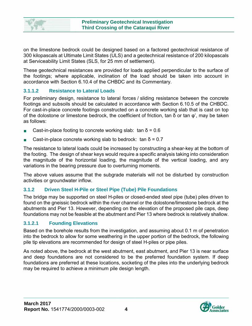
3.1.1.2 Resistance to Lateral Loads For preliminary design, resistance to lateral forces / sliding resistance between the concrete footings and subsoils should be calculated in accordance with Section 6.10.5 of the CHBDC. For cast-in-place concrete footings constructed on a concrete working slab that is cast on top of the dolostone or limestone bedrock, the coefficient of friction, tan δ or tan φ’, may be taken as follows:
Cast-in-place footing to concrete working slab: tan δ = 0.6
Cast-in-place concrete working slab to bedrock: tan δ = 0.7
The resistance to lateral loads could be increased by constructing a shear-key at the bottom of the footing. The design of shear keys would require a specific analysis taking into consideration the magnitude of the horizontal loading, the magnitude of the vertical loading, and any variations in the bearing pressure due to overturning moments.
The above values assume that the subgrade materials will not be disturbed by construction activities or groundwater inflow.
3.1.2 Driven Steel H-Pile or Steel Pipe (Tube) Pile Foundations The bridge may be supported on steel H-piles or closed-ended steel pipe (tube) piles driven to found on the gneissic bedrock within the river channel or the dolostone/limestone bedrock at the abutments and Pier 13. However, depending on the elevation of the proposed pile caps, deep foundations may not be feasible at the abutment and Pier 13 where bedrock is relatively shallow.
3.1.2.1 Founding Elevations Based on the borehole results from the investigation, and assuming about 0.1 m of penetration into the bedrock to allow for some weathering in the upper portion of the bedrock, the following pile tip elevations are recommended for design of steel H-piles or pipe piles.
As noted above, the bedrock at the west abutment, east abutment, and Pier 13 is near surface and deep foundations are not considered to be the preferred foundation system. If deep foundations are preferred at these locations, socketing of the piles into the underlying bedrock may be required to achieve a minimum pile design length.
March 2017 Report No. 1541774/2000/0003-002 4

Preliminary Geotechnical Investigation Third Crossing of the Cataraqui River
Table 2: Interpreted Design Pile Tip Elevations
Foundation Element
Borehole Number
Bedrock Surface Depth
(m)
Bedrock Surface
Elevation (m)
Design Pile Tip Elevation
(m)
West Abutment 16-201 4.60 70.85 70.75 Pier 1 NB 1 21.30 (1) 53.80 (1) 53.70 (1) Pier 2 NB 1, 16-103 25.06 (2) 49.84 (2) 49.74 (2) Pier 3 16-103 28.82 45.88 45.78 Pier 4 16-103, 16-104 30.39 (2) 44.24 (2) 44.14 (2) Pier 5 16-104 31.96 42.59 42.49 Pier 6 16-104, 16-105 34.39 (2) 40.12 (2) 40.02 (2) Pier 7 16-105 36.81 37.65 37.55 Pier 8 16-105, 16-106 30.34 (2) 44.21 (2) 44.11 (2) Pier 9 16-106 23.86 50.77 50.67
Pier 10 16-106, 16-101 22.88 (2) 51.78 (2) 51.68 (2) Pier 11 16-101 21.90 52.78 52.68 Pier 12 16-102 21.01 53.66 53.56 Pier 13 16-209 0.32 74.72 74.62
East Abutment 16-208 1.40 76.66 76.56
Notes: 1) Inferred based on sampler refusal; should be confirmed during detailed design. 2) Interpolated from adjacent borehole information; should be confirmed during
detailed design.
The boreholes put down within the river channel generally encountered stiff to very stiff silty clay to clay directly overlying the gneissic bedrock. The exceptions were at boreholes 16-102 and 16-105 (Piers 12 and 7, respectively) where compact to dense, granular, till-like deposits between 2.6 and 2.7 metres thick were encountered between the silty clay and the bedrock. At borehole 16-105, the till-like deposit contains cobbles and boulders and required diamond drilling to penetrate the lower 0.7 metres. Steel H-piles reinforced at the tip with a driving shoe should be able penetrate this layer and continue to the surface of the bedrock.
Due to the potential presence of cobbles and boulders within a discontinuous till deposit, steel H-piles are preferred over closed-ended steel pipe piles where the till deposit is present, as pipe piles are considered to pose a higher risk of “hanging up” or being deflected away from their vertical or battered orientation during installation, due to their larger end area.
March 2017 Report No. 1541774/2000/0003-002 5

Preliminary Geotechnical Investigation Third Crossing of the Cataraqui River
Steel H-piles or closed-ended pipe piles should be reinforced at the tip with a driving shoe to improve seating of the piles on the bedrock and to reduce the potential for damage to the piles during driving.
3.1.2.2 Axial Geotechnical Resistance For design of H-piles or closed-ended pipe piles driven to the estimated tip elevations provided in Section 3.1.2.1, the factored axial geotechnical resistances at ULS are shown in the table below. The ULS capacities provided were calculated considering a geotechnical resistance factor, φgu, of 0.4.
Table 3: Factored Axial Geotechnical Resistances
Pile Type
Factored Ultimate Geotechnical Axial Resistance (at ULS)
(kN)
HP 310 x 110 2,000
HP 360 x 132 2,400
HP 360 x 152 2,750
324 mm OD Pipe Pile 2,400
Serviceability Limit States (SLS) resistances do not apply to piles founded on the bedrock, since the SLS resistance for 25 mm of settlement is greater than the factored axial geotechnical resistance at ULS.
Pile installation should be in accordance with OPSS 903 (Deep Foundations). The drawings should incorporate the appropriate note stating that the piles should be equipped with bearing points and should be driven to refusal on bedrock. For piles driven to refusal on bedrock, and as described in OPSS 903, it is a generally accepted practice to reduce the hammer energy after abrupt peaking is met on the bedrock surface, and to then gradually increase the energy over a series of blows to seat the pile.
The preliminary geotechnical resistances provided above will have to be re-evaluated and modified as necessary during future stages of design in consideration of the additional subsurface investigation that will be carried out at the site.
3.1.2.3 Resistance to Lateral Loads Lateral loading could be resisted fully or partially by the use of battered piles. Alternatively, the resistance to lateral loading can be derived from the soil in front of the piles, and it may be assumed that this resistance will be nearly the same for vertical and inclined piles as indicated in Section C6.11.2.2 of the Commentary to the CHBDC.
March 2017 Report No. 1541774/2000/0003-002 6

Preliminary Geotechnical Investigation Third Crossing of the Cataraqui River
For preliminary design of the bridge, the SLS geotechnical response of the soil in front of the piles under lateral loading may be calculated using subgrade reaction theory where the coefficient of horizontal subgrade reaction, kh, is based on the equation given below, as described by Terzaghi (1955) and the Canadian Foundation Engineering Manual (3rd Edition).
For cohesionless soils:
Bznk h
h = Where: nh
z
B
is the constant of horizontal subgrade reaction, as given below;
is the depth (m); and,
is the pile diameter/width (m).
For cohesive soils:
Bs
k uh
67=
Where: su
B
is the undrained shear strength of the soil (kPa); and,
is the pile diameter/width (m).
The following ranges for the values of nh and su may be used in the structural analysis. The ranges in values reflect:
The variability in the subsurface conditions and the soil properties
The approximate nature of the analysis
The non-linear nature of the soil behaviour (such that nh is a function of deflection)
The two extremes of the design; the requirement for flexibility and the requirement for lateral resistance of horizontal loads
For piles arranged in closely spaced groups, the pile-soil-pile interaction causes the individual piles in a group to be less effective than a single pile. Theses “group effects” can be incorporated into the design using a method that modifies the coefficient of lateral subgrade reaction by some factor (i.e., a p-reduction factor). Generalized p-multipliers (i.e., p-reduction factors) for a range of pile spacings are provided in Section C6.11.3.4 of CHBDC.
Table 4: Soil Properties for Lateral Geotechnical Resistance of Deep Foundations
Location Elevation (m) Soil Type su (kPa) nh
(MN/m3)
BH 16-103 72.3 - 73.5 Peat/Organic Silt (River Bottom Sediments) - -
(Pier 3) 66.5 - 72.3 Very Stiff Silty Clay 95 to 125 - 54.0 - 66.5 Stiff Silty Clay 50 to 65 - 38.4 - 54.0 Firm to Stiff Silty Clay 60 to 75 - 29.1 - 38.4 Stiff to Very Stiff Silty Clay and Clayey Silt 80 to 100 - Below 29.1 Bedrock - -
March 2017 Report No. 1541774/2000/0003-002 7

Preliminary Geotechnical Investigation Third Crossing of the Cataraqui River
Location Elevation (m) Soil Type su (kPa) nh
(MN/m3) BH 16-104 68.2 - 73.7 Peat/Organic Silt (River Bottom
Sediments) - - (Pier 5) 63.0 - 68.2 Very Stiff Silty Clay 95 to 125 - 56.0 - 63.0 Stiff Silty Clay 78 to 90 - 32.5 - 56.0 Firm to Stiff Silty Clay 65 to 78 - Below 32.5 Bedrock - - BH 16-105 72.9 - 73.7 Peat/Organic Silt (River Bottom
Sediments) - - (Pier 7) 66.3 - 72.9 Very Stiff Silty Clay 95 to 125 - 50.0 - 66.3 Stiff Silty Clay 65 to 80 - 43.0 - 50.0 Firm to Stiff Silty Clay 55 to 65 - 40.0 - 43.0 Firm to Stiff Silty Clay 70 to 80 -
37.4 - 40.0 Very Dense Gravelly Sandy Silt (Glacial Till) - 10 to 15
Below 37.4 Bedrock - - BH 16-106 71.9 - 73.4 Peat/Organic Silt (River Bottom
Sediments) - - (Pier 9) 66.0 - 71.9 Very Stiff Silty Clay 90 to 125 - 60.0 - 66.0 Very Stiff Silty Clay 90 to 105 - 58.0 - 66.0 Stiff Silty Clay 70 to 85 - 51.1 - 58.0 Firm to Stiff Silty Clay 50 to 60 - Below 51.1 Bedrock - - BH 16-101 71.8 - 73.8 Peat/Organic Silt (River Bottom
Sediments) - - (Pier 11) 67.0 - 71.8 Very Stiff Silty Clay 95 to 125 - 53.1 - 67.0 Firm to Stiff Silty Clay 63 to 83 - Below 53.1 Bedrock - - BH 16-102 72.4 - 73.6 Peat/Organic Silt (River Bottom
Sediments) - - (Pier 12) 61.2 - 72.4 Very Stiff Silty Clay 95 to 125 - 56.7 - 61.2 Stiff Silty Clay 60 to 85 - 54.0 - 56.7 Compact to Very Dense Sandy Silt - 8 to 15 Below 54.0 Bedrock - -
The ULS geotechnical resistance to lateral loading may be calculated using passive earth pressure theory as outlined in Section C6.11.2.2.1 of the Commentary to the CHBDC.
March 2017 Report No. 1541774/2000/0003-002 8
Preliminary Geotechnical Investigation Third Crossing of the Cataraqui River
The ULS lateral resistance of a pile group may be estimated as the soil resistance of the group calculated as the passive earth pressure over an equivalent wall area with a depth of seven times the pile diameter and a width equal to the width of the pile group in plan, perpendicular to the direction of the applied lateral force.
For calculation of the ULS resistances a geotechnical resistance factor of 0.5 in accordance with the CHBDC is to be applied in calculating the horizontal resistance.
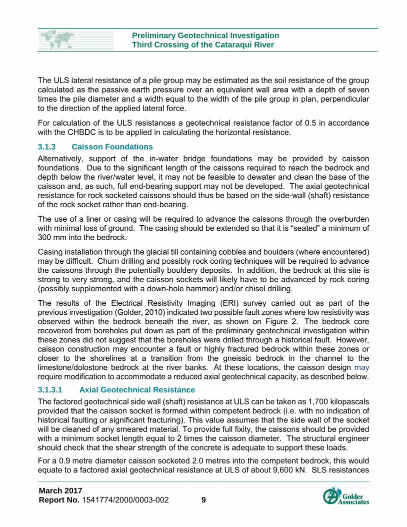
3.1.3 Caisson Foundations Alternatively, support of the in-water bridge foundations may be provided by caisson foundations. Due to the significant length of the caissons required to reach the bedrock and depth below the river/water level, it may not be feasible to dewater and clean the base of the caisson and, as such, full end-bearing support may not be developed. The axial geotechnical resistance for rock socketed caissons should thus be based on the side-wall (shaft) resistance of the rock socket rather than end-bearing.
The use of a liner or casing will be required to advance the caissons through the overburden with minimal loss of ground. The casing should be extended so that it is “seated” a minimum of 300 mm into the bedrock.
Casing installation through the glacial till containing cobbles and boulders (where encountered) may be difficult. Churn drilling and possibly rock coring techniques will be required to advance the caissons through the potentially bouldery deposits. In addition, the bedrock at this site is strong to very strong, and the caisson sockets will likely have to be advanced by rock coring (possibly supplemented with a down-hole hammer) and/or chisel drilling.
The results of the Electrical Resistivity Imaging (ERI) survey carried out as part of the previous investigation (Golder, 2010) indicated two possible fault zones where low resistivity was observed within the bedrock beneath the river, as shown on Figure 2. The bedrock core recovered from boreholes put down as part of the preliminary geotechnical investigation within these zones did not suggest that the boreholes were drilled through a historical fault. However, caisson construction may encounter a fault or highly fractured bedrock within these zones or closer to the shorelines at a transition from the gneissic bedrock in the channel to the limestone/dolostone bedrock at the river banks. At these locations, the caisson design may require modification to accommodate a reduced axial geotechnical capacity, as described below. 3.1.3.1 Axial Geotechnical Resistance The factored geotechnical side wall (shaft) resistance at ULS can be taken as 1,700 kilopascals provided that the caisson socket is formed within competent bedrock (i.e. with no indication of historical faulting or significant fracturing). This value assumes that the side wall of the socket will be cleaned of any smeared material. To provide full fixity, the caissons should be provided with a minimum socket length equal to 2 times the caisson diameter. The structural engineer should check that the shear strength of the concrete is adequate to support these loads. For a 0.9 metre diameter caisson socketed 2.0 metres into the competent bedrock, this would equate to a factored axial geotechnical resistance at ULS of about 9,600 kN. SLS resistances
March 2017 Report No. 1541774/2000/0003-002 9

Preliminary Geotechnical Investigation Third Crossing of the Cataraqui River
do not apply to caissons founded within the bedrock, because the SLS resistance for 25 mm of settlement will be greater than the factored axial geotechnical resistance at ULS. A fault or highly fractured bedrock at a caisson location would result in a reduced geotechnical side wall resistance. In this case, the foundation design may accommodate the reduced side wall shear resistance with deeper rock sockets, or through the use post-grouting to improve the side wall shear resistance. The presence of faulting or highly fractured bedrock should be confirmed with additional boreholes at the final pier locations during detailed design. 3.1.3.2 Resistance to Lateral Loads The resistance to lateral loading developed by the soil in front of the caissons, and the reductions due to group effects, may be determined as outlined in Section 3.1.2.3.
3.1.4 Pier Cap Construction Depending on the construction methodology selected, the in-water pier caps may need to be constructed on the river bed following installation of the deep foundation elements. In this case, the pier caps would be constructed of poured concrete within vertical formwork but bearing on the soil below.
The organic river bottom sediments are not considered suitable for support of pier cap construction. However, the underlying very stiff silty clay may be considered for support of mass concrete poured for pier construction. At the boreholes put down as part of the preliminary geotechnical investigation, the very stiff silty clay was typically encountered at depths of 0.8 to 2.0 metres below the river bottom (Elevations between about 71.5 to 72.3 metres), with the exception of borehole 16-104 put down at Pier 5 where the very stiff silty clay was encountered at a depth of about 5.5 metres below the river bottom (Elevation 67.8 metre).
An unfactored geotechnical resistance in the upper very stiff silty clay of 400 kPa at Ultimate Limit States (ULS) may be used for preliminary design of pier construction.
3.2 Seismic Design The CHBDC states that the seismic hazard values associated with the design earthquakes should be those established for the National Building Code of Canada (NBCC) by the Geological Survey of Canada (GSC). The GSC has developed a new set of seismic hazard maps (referred to as the 5th generation seismic hazard maps) that were made available for public use in December 2015.
3.2.1 Seismic Site Classification The seismic design provisions of the CHBDC depend, in part, on the shear wave velocity of the upper 30 metres of soil and/or rock below founding level or pile cap level. Shear wave velocity (Vs) profiles were measured during advancement of the Seismic Cone Penetration Tests (SCPTs) put down adjacent to boreholes 16-102, 16-104, and 16-106. Shear wave velocity profiles were also measured as part of a Multi-Spectral Analysis of Surface Waves (MASW) geophysical survey carried out on the east bank of the river, near the proposed east abutment, and
March 2017 Report No. 1541774/2000/0003-002 10

Preliminary Geotechnical Investigation Third Crossing of the Cataraqui River
Vertical Seismic Profiling (VSP) through the overburden soils and into the underlying bedrock at the west abutment (borehole 16-201). The results of the SCPTs, MASW, and VSP testing are presented in the Factual Data Report (Golder, 2016).
The shear wave velocities measured in the bedrock at the site ranged from about 750 to 1900 metres per second. When considered individually, spread footings founded on the bedrock at the abutments, where applicable, and Pier 13 may be considered to be Site Class B.
The shear wave velocities measured during advancement of the SCPTs put down at in-water borehole locations were used to develop an interpreted shear wave velocity profile for design of the in-water piers. Based on the travel-time average of the design shear wave velocity in the 30 metres of soil and rock within the river channel, the in-water pier locations (Piers 1 to 12) may be considered to be Site Class D.
As outlined in the CHBDC, if the bridge is a single continuous structure, the most conservative Site Class designation (Site Class D) should be used for design.
3.2.2 Spectral Response Values and Seismic Performance Category In accordance with Section 4.4.3.1 of the CHBDC and based on the location of the bridge (latitude 44.917 and longitude 75.198), the following are the reference Site Class C (reference) peak seismic hazard values based on the 5th generation seismic hazard maps published by the GSC.
Table 5: Spectral Acceleration Values for Reference Ground Condition Site Class C
Parameter Value at Given Probability of Exceedance in 50 Years
10% (475-year) 5% (975-year) 2% (2,475-year)
PGA 0.043 g 0.064 g 0.099 g T <= 0.2 s 0.076 g 0.109 g 0.163 g T = 0.5 s 0.052 g 0.075 g 0.111 g T = 1.0 s 0.030 g 0.044 g 0.066 g T = 2.0 s 0.015 g 0.022 g 0.034 g T = 5.0 s 0.004 g 0.006 g 0.009 g
T => 10.0 s 0.002 g 0.002 g 0.004 g
The values given above for the reference, Site Class C ground condition must be modified to the site-specific seismic site classification given in Section 3.2.1.in accordance with Section 4.4.3.3 of the CHBDC. As indicated in Section 4.4.3.3 the value of PGAref for use with Tables 4.2 to 4.9 of CHBDC shall be taken as 80 percent of PGA for Site Class C where Sa(0.2)/PGA is less than 2.0. Based on this requirement PGAref values of 0.079, 0.051 and 0.034 for the 2,475, 975 and 475 year return periods, respectively, were used.
March 2017 Report No. 1541774/2000/0003-002 11
Preliminary Geotechnical Investigation Third Crossing of the Cataraqui River
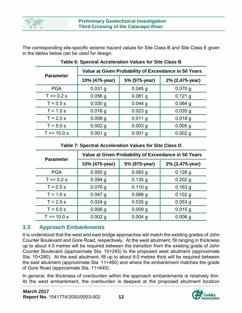
The corresponding site-specific seismic hazard values for Site Class B and Site Class E given in the tables below can be used for design.
Table 6: Spectral Acceleration Values for Site Class B
Parameter Value at Given Probability of Exceedance in 50 Years
10% (475-year) 5% (975-year) 2% (2,475-year)
PGA 0.031 g 0.045 g 0.070 g T <= 0.2 s 0.056 g 0.081 g 0.121 g T = 0.5 s 0.030 g 0.044 g 0.064 g T = 1.0 s 0.016 g 0.023 g 0.035 g T = 2.0 s 0.008 g 0.011 g 0.018 g T = 5.0 s 0.002 g 0.003 g 0.005 g
T => 10.0 s 0.001 g 0.001 g 0.002 g
Table 7: Spectral Acceleration Values for Site Class D
Parameter Value at Given Probability of Exceedance in 50 Years
10% (475-year) 5% (975-year) 2% (2,475-year)
PGA 0.055 g 0.083 g 0.128 g T <= 0.2 s 0.094 g 0.135 g 0.202 g T = 0.5 s 0.076 g 0.110 g 0.163 g T = 1.0 s 0.047 g 0.068 g 0.102 g T = 2.0 s 0.024 g 0.035 g 0.053 g T = 5.0 s 0.006 g 0.009 g 0.015 g
T => 10.0 s 0.002 g 0.004 g 0.006 g
3.3 Approach Embankments It is understood that the west and east bridge approaches will match the existing grades of John Counter Boulevard and Gore Road, respectively. At the west abutment, fill ranging in thickness up to about 4.0 metres will be required between the transition from the existing grade of John Counter Boulevard (approximate Sta. 10+245) to the proposed west abutment (approximate Sta. 10+280). At the east abutment, fill up to about 9.0 metres thick will be required between the east abutment (approximate Sta. 11+460) and where the embankment matches the grade of Gore Road (approximate Sta. 11+640).
In general, the thickness of overburden within the approach embankments is relatively thin. At the west embankment, the overburden is deepest at the proposed abutment location
March 2017 Report No. 1541774/2000/0003-002 12

Preliminary Geotechnical Investigation Third Crossing of the Cataraqui River
(borehole 16-201) where it consists of about 1.3 metres of granular fill overlying about 0.8 metres of peat and about 2.5 metres of clay and clayey silt. The overburden is underlain by dolostone bedrock at a depth of 4.6 metres. Within the footprint of the east embankment, the overburden consists of up to about 1.4 metres of surficial silty clay and sandy silt, which is underlain by limestone bedrock. 3.3.1 General Embankment Construction The peat, silty clay, and clayey silt are compressible soils that are expected to experience settlement under increased load. Therefore, it is recommended that all peat and clayey soil present within the footprint of the embankments be stripped prior to placement of the new embankment fill. Based on the boreholes put down within the proposed embankment footprints, a thickness of soil on the order of 0.6 metres will required stripping at the east embankment.
At the west embankment, about 2.1 metres of overburden (i.e., to the base of the peat deposit) near the abutment would require removal to eliminate the potential for post-construction settlement of the embankment. At the proposed west abutment, the existing ground surface is within a metre of the river level. Excavation would require some water-tight shoring to allow excavation below the existing river level. If the west abutment is to be supported on spread footings bearing on the dolostone bedrock, excavation for removal of the compressible soil within the embankment footprint could be carried out in conjunction with abutment footing construction. The depth and extent of stripping for embankment construction should be further assessed during future stages of design.
Fill such as Select Subgrade Material (SSM), conforming to that outlined in OPSS.MUNI 1010 (Material Specification for Aggregates) is considered to be suitable for embankment construction from a geotechnical perspective. Alternatively, rock fill may be considered as embankment fill as the side slopes of rock fill embankments may be constructed steeper than those constructed with SSM. However, the availability and proximity of SSM and/or rock fill may also influence selection of preferred embankment material.
The new embankment fill should be placed and compacted in accordance with OPSS.PROV 206 (Earth Excavation and Grading) and OPSS 501 (Compacting). To reduce erosion of the embankment side slopes constructed with SSM due to surface water runoff, placement of topsoil (OPSS 802 – Topsoil) and seeding (OPSS 804 – Seed and Cover) or pegged sod (OPSS 803 – Sodding) is recommended as soon as practicable after construction of the embankments. The erosion protection should be in accordance with OPSS 804 (Seed and Cover).
March 2017 Report No. 1541774/2000/0003-002 13

Preliminary Geotechnical Investigation Third Crossing of the Cataraqui River
3.3.2 Global Stability Static and seismic slope stability analyses of the proposed embankments were carried out with the commercially available slope stability analysis software, SlopeW (part of the software package, Geo-Studio 2007 Version 7, produced by Geo-Slope International Ltd.), to verify that a minimum factor of safety of 1.3 is achieved under static conditions and 1.1 under seismic conditions. These minimum factors of safety are considered appropriate for the proposed bridge approach embankments, considering the design requirements and the available field and laboratory testing data.
A Morgenstern-Price method was used to determine the factor of safety. The analyses were based on the existing topographic information provided by the design team and the available subsurface information.
The soil and bedrock stratigraphy between the borehole locations is based on an interpretation of the geological conditions of the area and consequently the actual conditions may vary from that used in the model. The soil parameters used in the analyses were based on in situ and laboratory testing data as well as published correlations.
Provided that the approach embankment side slopes are maintained no steeper than 2H:1V, the embankments should have an adequate minimum factor of safety of greater than 1.3 under static conditions.
The stability of the embankments was also evaluated under seismic loading conditions. The minimum factor of safety value that is typically required against instability during a seismic event is 1.1. A horizontal seismic coefficient of 0.04 (i.e., 50% of the PGA) was used for the pseudo-static analyses. Under these loading conditions the factor of safety of embankments constructed with 2H:1V side slopes was in excess of 1.1.
3.3.3 Static Settlement As described above, the organic peat deposit should be stripped from within the footprint of the proposed west approach embankment. At the east approach, the surficial silty clay should be stripped to the underlying dense to very dense sandy silt. With the removals described above, the post-construction settlement of the embankments is expected to be less than 25 millimetres. This settlement is expected to occur relatively quickly during and immediately following construction of the new approach embankments based on the nature of the soils at the site.
The above preliminary estimates do not include compression of the embankment fill itself, which would occur during and after the construction of the embankment depending on the type of materials used. The magnitude of fill compression may range from 0.5 to 1 percent of the height of the embankment, assuming approximately 98 percent compaction of the embankment fill is achieved, relative to the material’s standard Proctor maximum dry density. In the case where granular fill is used for embankment construction, settlement of the fill itself is expected to occur essentially during embankment construction, whereas non-granular earth fill materials are expected to exhibit some additional settlement over time.
March 2017 Report No. 1541774/2000/0003-002 14

Preliminary Geotechnical Investigation Third Crossing of the Cataraqui River
3.4 Design and Construction Considerations The following sections identify future construction issues that should be considered at this stage as they may impact the planning and preliminary design. 3.4.1 Excavation and Temporary Protection Systems If spread footings are adopted for support of the west abutment, the foundation excavations are expected to extend up to about 5 m below the existing John Counter Boulevard grade and the river level, into the water-bearing peat, clay, and clayey silt. The excavations for pile caps at the west abutment could be maintained at a higher elevation.
Where space permits, open-cut excavations into these materials should be carried out in accordance with the guidelines outlined in the Occupational Health and Safety Act (OHSA) for Construction Activities. The existing granular fill above the water table would be classified as Type 3 soil, based on the OHSA. The fill, peat, clay and clayey silt below the water table would be classified as Type 4 soil.
According to OHSA excavations that extend to, or into, Type 3 soils should be made with side slopes no steeper than 1 horizontal to 1 vertical (1H:1V). Excavations that extend to, or into, Type 4 soils should be made with side slopes no steeper than 3 horizontal to 1 vertical (3H:1V).
At this preliminary stage, it is anticipated that temporary protection systems would likely be required to facilitate the excavation to foundation or pile cap level for the new abutments and construction of the approach embankments. The temporary excavation support system should be designed and constructed in accordance with OPSS 539 (Temporary Protection Systems).
The selection and design of the protection system will be the responsibility of the Contractor. However, the following comments are provided to aid in the costing and assessment of temporary protection system options for this site:
It is considered that steel H-piles and wood lagging would not be suitable as it is a permeable system that would not allow for control of groundwater levels within the excavation.
An interlocking steel sheet pile system and continuous concrete (secant pile or diaphragm) walls are essentially “water tight” systems that do not require active groundwater lowering and groundwater control, and would facilitate groundwater lowering prior to excavation.
Whatever system is chosen, the piles (or diaphragm walls) should be pinned at their base or socketed into the bedrock to achieve fixity.
3.4.2 Groundwater and Surface Water Control The groundwater level at the east and west abutments is anticipated to be at or near the river level. If excavation into the overburden at the west approach or abutment is required, the excavations may extend into the water bearing fill, peat, clay and clayey silt. The excavation walls will require shoring, as described in Section 3.4.1.
March 2017 Report No. 1541774/2000/0003-002 15

Preliminary Geotechnical Investigation Third Crossing of the Cataraqui River
According to Ontario Regulation 63/16 and Ontario Regulation 387/04, a Permit to Take Water (PTTW) is required from the Ministry of the Environment and Climate Change (MOECC) if a volume of water greater than400,000 L/day is pumped from the excavations. If the volume of water to be pumped will be less than 400,000 L/day, but more than 50,000 L/day, the water taking will not require a PTTW, but will need to be registered in the Environmental Activity and Sector Registry (EASR) as a prescribed activity. The anticipated dewatering rate should be confirmed at the future design stage to confirm if either a PTTW or EASR is required for this site.
It is understood that intermittent spring groundwater flow exits the existing topography within the proposed east approach embankment footprint at locations between about Sta. 11+500 and Sta. 11+600. The surface water at each of these locations currently flows roughly northwest within natural swales towards the river. The surface water could be transmitted across and out of the embankment via granular drains constructed across the embankment footprint along the existing natural outlets. The granular drains could consist of clear crushed, free-draining granular fill wrapped in a non-woven filter geotextile to prevent migration of fines from the embankment fill into the drain structure. The alignment and details of the granular drain would depend on the alignment/location of the natural outlets and the anticipated design flow of the surface water.
The granular drains could be built up to the edge of the embankment and faced with rip rap / rock fill, or could transition to an outlet pipe to exit at the embankment toe (i.e., no significant headwall structure would be required if exiting the embankment side slope). The granular drain or outlet pipe should exit to a drainage swale outlet.
Quantification of the anticipated flows and sizing of the granular drains should be carried out at the detailed design stage.
3.5 Recommendations for Further Work in Detail Design Additional subsurface investigation will be required during detailed design of the project to suit the final design and mitigate any identified constructions risks, and to further assess and/or confirm the subsurface conditions and the preliminary recommendations provided in this report. Such additional subsurface investigation could include:
Confirmation of the bedrock surface elevation at the in-water pier locations where borehole drilling has not yet been completed, to confirm the founding elevation for deep foundations.
Assessment of the depth and extent of stripping of topsoil/organic soils and fill materials within the footprint of the east approach embankments.
Further assessment of the groundwater and surface water characteristics near and within the proposed east approach embankment.
March 2017 Report No. 1541774/2000/0003-002 16
Golder Associates Ltd. Page 1 of 3
IMPORTANT INFORMATION AND LIMITATIONS OF THIS REPORT
Standard of Care: Golder Associates Ltd. (Golder) has prepared this report in a manner consistent with that level of care and skill ordinarily exercised by members of the engineering and science professions currently practising under similar conditions in the jurisdiction in which the services are provided, subject to the time limits and physical constraints applicable to this report. No other warranty, expressed or implied is made. Basis and Use of the Report: This report has been prepared for the specific site, design objective, development and purpose described to Golder by the Client, J.L Richards & Associates Ltd. The factual data, interpretations and recommendations pertain to a specific project as described in this report and are not applicable to any other project or site location. Any change of site conditions, purpose, development plans or if the project is not initiated within eighteen months of the date of the report may alter the validity of the report. Golder cannot be responsible for use of this report, or portions thereof, unless Golder is requested to review and, if necessary, revise the report. The information, recommendations and opinions expressed in this report are for the sole benefit of the Client. No other party may use or rely on this report or any portion thereof without Golder's express written consent. If the report was prepared to be included for a specific permit application process, then the client may authorize the use of this report for such purpose by the regulatory agency as an Approved User for the specific and identified purpose of the applicable permit review process, provided this report is not noted to be a draft or preliminary report, and is specifically relevant to the project for which the application is being made. Any other use of this report by others is prohibited and is without responsibility to Golder. The report, all plans, data, drawings and other documents as well as all electronic media prepared by Golder are considered its professional work product and shall remain the copyright property of Golder, who authorizes only the Client and Approved Users to make copies of the report, but only in such quantities as are reasonably necessary for the use of the report by those parties. The Client and Approved Users may not give, lend, sell, or otherwise make available the report or any portion thereof to any other party without the express written permission of Golder. The Client acknowledges that electronic media is susceptible to unauthorized modification, deterioration and incompatibility and therefore the Client cannot rely upon the electronic media versions of Golder's report or other work products. The report is of a summary nature and is not intended to stand alone without reference to the instructions given to Golder by the Client, communications between Golder and the Client, and to any other reports prepared by Golder for the Client relative to the specific site described in the report. In order to properly understand the suggestions, recommendations and opinions expressed in this report, reference must be made to the whole of the report. Golder cannot be responsible for use of portions of the report without reference to the entire report. Unless otherwise stated, the suggestions, recommendations and opinions given in this report are intended only for the guidance of the Client in the design of the specific project. The extent and detail of investigations, including the number of test holes,
Golder Associates Ltd. Page 2 of 3
necessary to determine all of the relevant conditions which may affect construction costs would normally be greater than has been carried out for design purposes. Contractors bidding on, or undertaking the work, should rely on their own investigations, as well as their own interpretations of the factual data presented in the report, as to how subsurface conditions may affect their work, including but not limited to proposed construction techniques, schedule, safety and equipment capabilities. Soil, Rock and Groundwater Conditions: Classification and identification of soils, rocks, and geologic units have been based on commonly accepted methods employed in the practice of geotechnical engineering and related disciplines. Classification and identification of the type and condition of these materials or units involves judgment, and boundaries between different soil, rock or geologic types or units may be transitional rather than abrupt. Accordingly, Golder does not warrant or guarantee the exactness of the descriptions. Special risks occur whenever engineering or related disciplines are applied to identify subsurface conditions and even a comprehensive investigation, sampling and testing program may fail to detect all or certain subsurface conditions. The environmental, geologic, geotechnical, geochemical and hydrogeologic conditions that Golder interprets to exist between and beyond sampling points may differ from those that actually exist. In addition to soil variability, fill of variable physical and chemical composition can be present over portions of the site or on adjacent properties. The professional services retained for this project include only the geotechnical aspects of the subsurface conditions at the site, unless otherwise specifically stated and identified in the report. The presence or implication(s) of possible surface and/or subsurface contamination resulting from previous activities or uses of the site and/or resulting from the introduction onto the site of materials from off-site sources are outside the terms of reference for this project and have not been investigated or addressed. Soil and groundwater conditions shown in the factual data and described in the report are the observed conditions at the time of their determination or measurement. Unless otherwise noted, those conditions form the basis of the recommendations in the report. Groundwater conditions may vary between and beyond reported locations and can be affected by annual, seasonal and meteorological conditions. The condition of the soil, rock and groundwater may be significantly altered by construction activities (traffic, excavation, groundwater level lowering, pile driving, blasting, etc.) on the site or on adjacent sites. Excavation may expose the soils to changes due to wetting, drying or frost. Unless otherwise indicated the soil must be protected from these changes during construction. Sample Disposal: Golder will dispose of all uncontaminated soil and/or rock samples 90 days following issue of this report or, upon written request of the Client, will store uncontaminated samples and materials at the Client's expense. In the event that actual contaminated soils, fills or groundwater are encountered or are inferred to be present, all contaminated samples shall remain the property and responsibility of the Client for proper disposal. Follow-Up and Construction Services: All details of the design were not known at the time of submission of Golder's report. Golder should be retained to review the final design, project plans and documents prior to construction, to confirm that they are consistent with the intent of Golder's report.

Golder Associates Ltd. Page 3 of 3
During construction, Golder should be retained to perform sufficient and timely observations of encountered conditions to confirm and document that the subsurface conditions do not materially differ from those interpreted conditions considered in the preparation of Golder's report and to confirm and document that construction activities do not adversely affect the suggestions, recommendations and opinions contained in Golder's report. Adequate field review, observation and testing during construction are necessary for Golder to be able to provide letters of assurance, in accordance with the requirements of many regulatory authorities. In cases where this recommendation is not followed, Golder's responsibility is limited to interpreting accurately the information encountered at the borehole locations, at the time of their initial determination or measurement during the preparation of the Report. Changed Conditions and Drainage: Where conditions encountered at the site differ significantly from those anticipated in this report, either due to natural variability of subsurface conditions or construction activities, it is a condition of this report that Golder be notified of any changes and be provided with an opportunity to review or revise the recommendations within this report. Recognition of changed soil and rock conditions requires experience and it is recommended that Golder be employed to visit the site with sufficient frequency to detect if conditions have changed significantly. Drainage of subsurface water is commonly required either for temporary or permanent installations for the project. Improper design or construction of drainage or dewatering can have serious consequences. Golder takes no responsibility for the effects of drainage unless specifically involved in the detailed design and construction monitoring of the system.

SITE
378000
378000
379000
379000
380000
380000
381000
381000
382000
382000
383000
383000
384000
384000
385000
385000
386000
386000
387000
387000
4898
000
4898
000
4899
000
4899
000
4900
000
4900
000
4901
000
4901
000
4902
000
4902
000
4903
000
4903
000
4904
000
4904
000
4905
000
4905
000
4906
000
4906
000
4907
000
4907
000
LEGEND
PROPOSED ALIGNMENT
Pat
h: N
:\Act
ive\
Spa
tial_
IM\J
.L._
Ric
hard
s&A
ssoc
iate
s_Li
mite
d\C
atar
aqui
_Cro
ssin
g\99
_PR
OJ\
1541
774_
JLR
_3rd
Cro
ssin
g\40
_PR
OD
\Pha
se20
00\G
eote
ch\1
5417
74-2
000-
0003
-01.
mxd
SITE
IF T
HIS
ME
AS
UR
EM
EN
T D
OES
NO
T M
ATC
H W
HAT
IS S
HO
WN
, TH
E SH
EET
SIZE
HA
S B
EEN
MO
DIF
IED
FR
OM
:25
mm
0
1. THIS FIGURE IS TO BE READ IN CONJUNCTION WITH THE ACCOMPANYING GOLDERASSOCIATES LTD. REPORT NO. 1541774-2000-0003
1. PROJECTION: TRANSVERSE MERCATOR DATUM: NAD 83COORDINATE SYSTEM: UTM ZONE 18 VERTICAL DATUM: CGVD28
1:50,000 METRES
2000/0003 0 1PROJECT NO. PHASE/TASK FIGURE
KEY MAP
CLIENT
J.L. RICHARDS & ASSOCIATES LIMITED
GEOTECHNICAL INVESTIGATIONTHIRD CROSSING OF THE CATARAQUI RIVERKINGSTON, ONTARIOTITLE
KEY PLAN
CONSULTANT
REV.
2016-11-29
----
JEM
MJK
MSS
YYYY-MM-DD
DESIGNED
PREPARED
REVIEWED
APPROVED
1541774
0 1,000 2,000500
REFERENCE(S)
NOTE(S)
PROJECT
4 901 750 N 4 901 750 N
382
750
E38
2 75
0 E
4 901 500 N 4 901 500 N
382
500
E38
2 50
0 E
382
250
E38
2 25
0 E
382
000
E38
2 00
0 E
381
750
E38
1 75
0 E
383
000
E38
3 00
0 E
383
250
E38
3 25
0 E
383
500
E38
3 50
0 E
76.30
9
0
0
m
m
Ø
S
A
N
H
H
H
B
B
H
250 m
m Ø
W
M
200 m
m Ø
W
M
400 mm
Ø W
M
H
H
200 m
m
Ø
F
O
R
C
E
M
A
IN
200 m
m
Ø
F
O
R
C
E
M
A
IN
H
B
MH79.24
BH/SCPT 16-102
BH 16-103
BH/SCPT 16-104
BH 16-105
BH/SCPT 16-106
BH 16-201
BH 16-202
BH 16-203BH 16-204
BH 16-205BH 16-206
BH 16-207
BH 16-208
BH 16-209
BH 10-1
BH 10-2
NC 1
NC 2NC 3
BH 10-3
NB 1
NB 4
NB 2
NB 3
PIER 2PIER 2
W.ABUT.BRGS.W.ABUT.BRGS.
E.ABUT.BRGS.E.ABUT.BRGS.
PIER 3PIER 3
PIER 4PIER 4
PIER 5PIER 5
PIER 6PIER 6
PIER 7PIER 7
PIER 8PIER 8
PIER 9PIER 9
PIER 10PIER 10
PIER 11PIER 11
PIER 12PIER 12
PIER 13PIER 13
ARCHARCH
PIER 1PIER 1
10+30010+400
10+50010+600
10+70010+800
10+90011+000
11+200 11+300 11+400
10+300
10+200
10+400
10+500
10+600
10+700
10+800
10+900
11+000
1+100
11+200
11+300
1+400
1+500
PIER 2
W.ABUT.BRGS.
E.ABUT.BRGS.
PIER 3
PIER 4
PIER 5
PIER 6
PIER 7
PIER 8
PIER 9
PIER 10
PIER 11
PIER 12
PIER 13
ARCH
PIER 1
℄ PIER 1℄ PIER 2
℄ PIER 3℄ PIER 4
℄ PIER 5℄ PIER 6
℄ PIER 7℄ PIER 8
℄ PIER 9 ℄ PIER 10 ℄ PIER 11 ℄ ARCH ℄ PIER 12 ℄ PIER 13 ℄ EAST ABUT.
℄ WEST ABUT.
11+600 11+700 11+800
BA
RK
ER
D
R.
G
O
R
E
R
D
.
JOH
N C
OU
NT
ER
BLV
D.
M
O
N
T
R
E
A
L
S
T
.
BR
ICE
LAN
D S
T.
H
W
Y
. 1
5
BH 16-102B
ERI SURVEY LINE(GOLDER, 2010)
11+500
MASW LINE(APPROXIMATE)
BH 16-101
11+100
POSSIBLEFAULTZONE
POSSIBLEFAULTZONE
APPROXIMATE EXISTING GROUND/RIVER BOTTOM
20
25
30
35
40
45
50
55
60
65
70
75
80
85
90
95
100
20
25
30
35
40
45
50
55
60
65
70
75
80
85
90
95
100
10+200.00 10+300.00 10+400.00 10+500.00 10+600.00 10+700.00 10+800.00 10+900.00 11+000.00 11+100.00 11+200.00 11+300.00 11+400.00 11+500.00 11+600.00 11+700.00 11+800.0010+100.0010+000.00STATIONING
ELE
VA
TIO
N, m
etre
s
ELE
VA
TIO
N, m
etre
s
℄ WEST ABUT.
℄ PIER 1 ℄ PIER 2 ℄ PIER 3 ℄ PIER 4 ℄ PIER 5 ℄ PIER 6 ℄ PIER 7 ℄ PIER 8 ℄ PIER 9 ℄ PIER 10 ℄ PIER 12 ℄ PIER 13 ℄ EAST ABUT.℄ PIER 11
℄ ARCH
BH 16-204 BH 16-203
BH 16-202BH 16-201
NB 1 BH 16-103 BH/SCPT 16-104 BH 16-105 BH/SCPT 16-106 BH 16-101 BH/SCPT 16-102 BH 16-209
BH 16-208 BH 16-207 BH 16-206
BH 16-205105 105
WL
APPROXIMATE MEANWATER LEVEL DURING2016 INVESTIGATION(~74.9 m ELEV.)
INTERPRETED BEDROCK SURFACE
?
?
?
??
??
?
?
? ? ? ?
?
?
POSSIBLEFAULT ZONE
POSSIBLEFAULTZONE
BH 10-2
GEOTECHNICAL INVESTIGATIONTHIRD CROSSING OF THE CATARAQUI RIVERKINGSTON, ONTARIO
J.L. RICHARDS & ASSOCIATES LIMITED
025
mm
1541774PHASE2000/0003
FIGURE
20
2016-05-30
JM
----
MJK
MSS
SITE PLAN AND PROFILE TITLE
PROJECT NO. REV.
PROJECT
CLIENT
CONSULTANT
PREPARED
DESIGNED
REVIEWED
APPROVED
YYYY-MM-DD
Pat
h: \\
gold
er.g
ds\g
al\o
ttaw
a\A
ctiv
e\S
patia
l_IM
\J.L
._R
icha
rds&
Ass
ocia
tes_
Lim
ited\
Cat
araq
ui_C
ross
ing\
99_P
RO
J\15
4177
4_JL
R_3
rdC
ross
ing\
40_P
RO
D\P
hase
2000
\Geo
tech
\ |
File
Nam
e: 1
5417
74-2
000-
0003
-02.
dwg
IF T
HIS
ME
AS
UR
EM
EN
T D
OE
S N
OT
MA
TCH
WH
AT
IS S
HO
WN
, TH
E S
HE
ET
SIZ
E H
AS
BE
EN
MO
DIF
IED
FR
OM
: AN
SI B
PLANSCALE 1:5,000
PROFILEHORIZ. SCALE 1:5,000VERT. SCALE 1:1,000
1. BRIDGE IS STILL UNDER DESIGN AND IS INCLUDED FOR ILLUSTRATION PURPOSES ONLY.2. THIS FIGURE IS TO BE READ IN CONJUNCTION WITH THE ACCOMPANYING GOLDER ASSOCIATES LTD. DOCUMENT
No. 1541774-2000-0003
1. BASE PLAN AND ALIGNMENT SUPPLIED IN ELECTRONIC FORMAT BY J.L. RICHARDS & ASSOCIATES LIMITED ONOCTOBER 31, 2016, FILE NO. B-101v6B_Borehole_Locations.dwg
2. PROJECTION: TRANSVERSE MERCATOR DATUM: NAD 83, COORDINATE SYSTEM: UTM ZONE 18, VERTICAL DATUM:CGVD28
APPROXIMATE BOREHOLE LOCATION, CURRENT INVESTIGATION
LEGEND
NOTE(S)
REFERENCE(S)
WATER
ASPHALTIC CONCRETE
FILL
TOPSOIL
SILTY CLAY to CLAY
CLAYEY SILT
SILT
SANDY SILT
SILTY SAND
SAND AND GRAVEL
GLACIAL TILL
LIMESTONE
DOLOSTONE
GRANITE
GNEISS
APPROXIMATE BOREHOLE LOCATION, PREVIOUS INVESTIGATION BY GOLDERASSOCIATES LTD., REPORT NO. 09-1121-0016
APPROXIMATE DYNAMIC CONE LOCATION, PREVIOUS INVESTIGATION BY STRATAENGINEERING CORP. (1991)
APPROXIMATE BOREHOLE LOCATION, PREVIOUS INVESTIGATION BY STRATAENGINEERING CORP. (1991)
SUBSURFACE STRATIGRAPHY
BH 16-101
STRATIGRAPHYSPT, N VALUE
BOREHOLE IDENTIFIER