Embed Size (px)
Citation preview

DESIGN OF TEMPORARY WORKS FOR THE CONSTRUCTION OF FERGUSSON WHARF
GRAHAM FROST1; RICHARD GRAY2; MARK SEYMOUR3
1 Chief Engineer (retired), Fletcher Construction Company Ltd 2 Design Engineer, Fletcher Construction Company Ltd
3 Project Engineer, Brian Perry Civil Ltd SUMMARY The construction of the Fergusson wharf extends the existing Fergusson Container Terminal an additional 34 m into the Waitemata harbour, Auckland, New Zealand. The wharf provides the Terminal with an additional 9 900 m2 of container and cargo storage area and 295 m of berth for container ships along the Northern face of the Terminal. Fletcher Construction Company Ltd trading as Brian Perry Civil Ltd was contracted to construct the reinforced concrete wharf on behalf of Ports of Auckland Ltd. Construction is due to be completed in 2017. The paper outlines the challenges involved in reinforced concrete wharf construction, and describes the construction methodologies and temporary works designs adopted at Fergusson wharf to enable its safe and efficient construction with several operations occurring simultaneously and all suspended above the waters of the Waitemata harbour. The paper focuses on the design and operation of a travelling form system. This system is suspended from the permanent works’ piles and supports the staged concrete pour of the wharf deck. The paper touches on other temporary works designs such as the staging used to enable construction of the piles and the dredging of the harbour seabed surrounding the wharf.
INTRODUCTION The proposed Fergusson wharf is to be located on the Waitemata harbour, Auckland, New Zealand, as shown in Figure 1. The wharf is to form part of the Fergusson Container Terminal which is owned and operated by Ports of Auckland Ltd (POAL).
Figure 1. Locality of proposed Fergusson Wharf (courtesy Google maps)
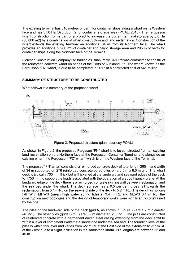
The existing terminal has 610 metres of berth for container ships along a wharf on its Western face and has 37.8 Ha (378 000 m2) of container storage area (POAL, 2016). The Fergusson wharf construction forms part of a project to increase the current terminal storage by 3.6 Ha (36 000 m2) by a combination of wharf construction and land reclamation. Construction of the wharf extends the existing Terminal an additional 34 m from its Northern face. The wharf provides an additional 9 900 m2 of container and cargo storage area and 295 m of berth for container ships along the Northern face of the Terminal. Fletcher Construction Company Ltd trading as Brian Perry Civil Ltd was contracted to construct the reinforced concrete wharf on behalf of the Ports of Auckland Ltd. The wharf, known as the Fergusson “FN” wharf, is due to be completed in 2017 at a contracted cost of $41 million. SUMMARY OF STRUCTURE TO BE CONSTRUCTED What follows is a summary of the proposed wharf.
Figure 2. Proposed structure (plan, courtesy POAL)
As shown in Figure 2, the proposed Ferguson “FN” wharf is to be constructed from an existing land reclamation on the Northern face of the Fergusson Container Terminal and alongside an existing wharf, the Fergusson “FZ” wharf, which is on the Western face of the Terminal. The proposed “FN” wharf consists of a reinforced concrete deck of total length 295 m and width of 34 m supported on 276 reinforced concrete bored piles on a 6.5 m x 6.0 m grid. The wharf deck is typically 700 mm thick but is thickened at the landward and seaward edges of the deck to 1750 mm to support the loads associated with the operation of a 2000 t gantry crane. At the landward edge of the deck there is a reinforced concrete skirting wall between reclamation and the sea bed under the wharf. The deck surface has a 0.5 per cent cross fall towards the reclamation, from 5.4 m RL on the seaward side of the deck to 5.2 m RL. The deck has no long fall. With MHWS (mean high water spring tide) at 3.4 m RL and MLWS 0.4 m RL, the construction methodologies and the design of temporary works were significantly constrained by the tide. The piles on the landward side of the deck (grid A, as shown in Figure 2) are 1.2 m diameter (46 no.). The other piles (grids B to F) are 0.9 m diameter (230 no.). The piles are constructed of reinforced concrete with a permanent driven steel casing extending from the deck soffit to within a layer of competent Waitemata sandstone under the sea bed. The founding level of the piles is within this layer and varies from -22 m RL at the East side of the extension to -27 m RL at the West due to a slight inclination in the sandstone strata. Pile lengths are between 35 and 40 m.
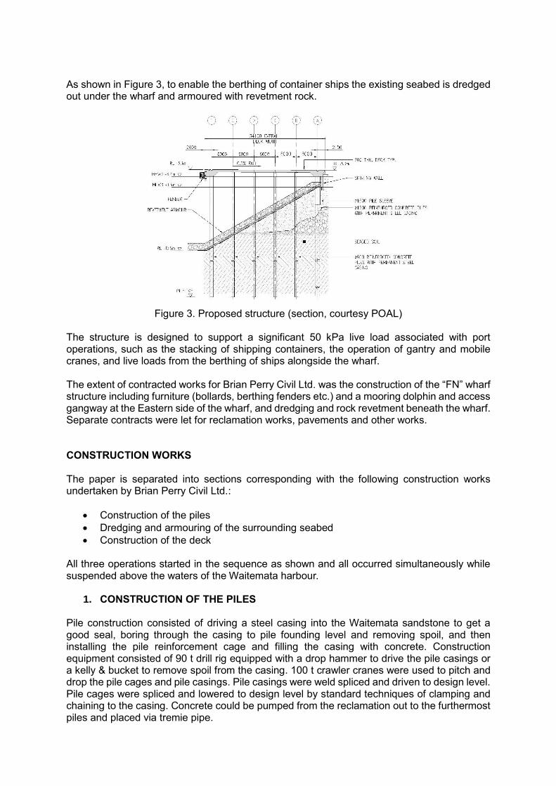
As shown in Figure 3, to enable the berthing of container ships the existing seabed is dredged out under the wharf and armoured with revetment rock.
Figure 3. Proposed structure (section, courtesy POAL)
The structure is designed to support a significant 50 kPa live load associated with port operations, such as the stacking of shipping containers, the operation of gantry and mobile cranes, and live loads from the berthing of ships alongside the wharf. The extent of contracted works for Brian Perry Civil Ltd. was the construction of the “FN” wharf structure including furniture (bollards, berthing fenders etc.) and a mooring dolphin and access gangway at the Eastern side of the wharf, and dredging and rock revetment beneath the wharf. Separate contracts were let for reclamation works, pavements and other works. CONSTRUCTION WORKS The paper is separated into sections corresponding with the following construction works undertaken by Brian Perry Civil Ltd.:
Construction of the piles
Dredging and armouring of the surrounding seabed
Construction of the deck All three operations started in the sequence as shown and all occurred simultaneously while suspended above the waters of the Waitemata harbour.
1. CONSTRUCTION OF THE PILES Pile construction consisted of driving a steel casing into the Waitemata sandstone to get a good seal, boring through the casing to pile founding level and removing spoil, and then installing the pile reinforcement cage and filling the casing with concrete. Construction equipment consisted of 90 t drill rig equipped with a drop hammer to drive the pile casings or a kelly & bucket to remove spoil from the casing. 100 t crawler cranes were used to pitch and drop the pile cages and pile casings. Pile casings were weld spliced and driven to design level. Pile cages were spliced and lowered to design level by standard techniques of clamping and chaining to the casing. Concrete could be pumped from the reclamation out to the furthermost piles and placed via tremie pipe.

Turning to the temporary works to enable pile construction, the piles alongside the reclamation, i.e. those on grid A, were constructed by supporting the drill rigs on 2 beams each of 2 no. 700 mm deep I beams. The beams were 9.0 m long and supported on the existing reclamation at one end and on temporary driven casings and crossheads at the other end. The staging system described below was not used for piles on grid A as due to the stiffness of the grid A piles they could not be manoeuvred to suit the staging tolerance. Access to the subsequent piles from grid B to F was by system of staging supported on only the permanent works piles. The staging system consisted of two types staging platforms, a standard platform and a cantilever platform. The platforms were modular i.e. they could be placed and used independently of each other. The standard platform was a 6.5 m x 6.0 m grid of braced 610UB beams with 200 thick layer of timber on top for traction with the tracks of the drill rigs. Due to potential clashes with pile starters the beams could be supported by bearing on only the 16 mm thick steel pile casings rather than on the pile concrete. The standard platforms had to support the laden drill rigs & cranes tracking in both the North-South (N-S) and West-East (W-E) directions and to support un-laden rigs & cranes counter-rotating their tracks in order to rotate their direction from N-S to W-E and vice versa. The standard platforms were only required for the rigs & cranes to access the cantilevered platforms. The cantilevered platforms led the staging & it was from these platforms that pile construction was done. Due to the rectangular pile grid two types of cantilevered platforms were needed so that the piling equipment could be orientated in the N-S and W-E directions. The platforms measured 6.0 x 13.0 m for the platform in the W-E direction and 6.5 m x 12.0 m for the N-S. All the piles on grid F were constructed from 1 no. N-S platform, and 2 no. W-E platforms were positioned between grids B & C and D & E to construct all the piles along these grids. The standard platform was designed as two-way grid simply-supported at four corners on the pile casings. The cantilever platform on the other hand was designed to have a bearing support on the 2 no. leading span piles and to be tied down at the 2 no. back span piles. The cantilevered platform was constructed from 610UB beams supported by 2 no. 610UB V braces bearing down to a 1200 deep beam between the leading piles. This beam was supported on corbels welded to the pile casing. The platform was tied down at the trailing piles by 8 no. threaded rods through a corbel welded to the pile casing. Separable pile guide frames suspended either side of the cantilever enabled two piles to be constructed with each pitch of the platform. The guide frames used threaded rods and sleeved SHS sections to fine-tune the position of the casing in plan to the design set out. Restrictions imposed on construction equipment were to stop the staging from overturning. Depending on the drill rig considered, and its set up (such as boom length, weight carried and radius and slew worked at) the centre of rotation of the rig could extend approximately 3.0 m ahead of the leading pile.

A staging platform set up is shown in Figure 4.
Figure 4. Staging platform for cantilevered piling platform. Foreground shows pitched pile casing in guide frame & drill rig on W-E cantilevered platform with bracing under to leading pile and tie downs to rear pile. Background shows drill rig with gooseneck on N-S platform.
2. DREDGING & ARMOURING OF THE SURROUNDING SEABED
Dredging of the seabed under and surrounding the wharf was needed so that ships with deep drafts could berth at the wharf. The dredged area was to be armoured with rock to stabilise the area and reduce scouring. The digging and placing of rock needed to occur prior to the deck being constructed. But due to the distances involved (i.e. the seaward edge of the wharf was 34 m from the existing reclamation) it could not occur from land. Instead of adopting the typical construction method in this situation of digging and placing rock from an excavator on a barge, a system of temporary staging suspended on the permanent works piles was proposed. This staging supported a 280 t mining excavator which was used to dig out the mudcrete & some Waitemata stone and place the revetment rock. The staging design specified strict working conditions on the excavator so as to avoid inadvertent loading on the staging & piles. As shown in Figure 6 the staging consisted of 2 no. 700 mm deep I beams under each track of the excavator. The beams were 6 m long and braced at quarter-span. These beams were notched at the ends 300 mm to allow additional excavator reach. The notching required doubler plates to the web & several plates to transfer flange forces. The beams were simply supported on crossheads constructed from 4 no. 530 UC beams which in turn were supported in bearing on top of the pile casings.

Figure 5. 280 t excavator, supported on staging beams & crossheads, placing revetment rock
from a barge. Due to the difficulty in achieving tight tolerances on pile positioning imposed by the staging support an alternative support collar was hung from the pile casing on grid A. This collar permitted a shortened crosshead to be placed and the staging beams to be aligned along the pile design grids even though the piles themselves varied from these grids. The piles on grids B to F were found to be sufficiently slender that they could be manoeuvred onto the grid & so suit the original crosshead set up.
3. CONSTRUCTION OF THE DECK The 34 m x 295 m long deck is poured in 23 no. pours each of 13 m x 34 m (400 m3 per pour). A system of travelling panels was proposed as it suited the pouring sequence, enabling easier and safer erection & extraction of forms between pours and avoiding access issues (noting that following a pour the forms are located under a completed deck), promising a faster turn-around time on deck construction compared to a traditional form system. A similar type of system had already been adopted by Fletcher Construction Company Ltd to construct the Northport wharf at Marsden Point. As shown in Figure 6 & 7 the travelling form system consisted of 5 no. 4.1 m wide x 21 m long main panels for the interior bays and 1 no. 1.5 m wide x 21 m long main panel for the exterior bay on the seaward side of grid F. The panels were constructed from 610 UB beams orientated in the longitudinal direction of the deck braced by 4.1 m long transverse 410 UB beams at 1.7 m centres. Supported on the cross-braces were steel SHS joists which in turn supported ply forms. The cross-braces were cranked at the panels near grids A and F to suit the slope of the deck soffit. Walkways were hung from the panels to enable erection & extraction of forms and these walkways travelled with the beams.

Figure 6. Travelling formwork system (plan)
Figure 7. Travelling form system (section)
Inbetween the main panels were placed 1.9 m wide infill panels comprising timber joists with ply forms. The infill panels were supported off the main panels by a screw jacking system. The screw jacks allowed the infill panels to be lowered, and so removed, independently of the main panels. The infill panels had to be removed prior to launching the main panels forward otherwise the infill panels would clash with the piles. Tie bars between the main panels were placed at 1.7 m centres in line with the cross braces of the main panels to provide a continuity of path for the lateral and inclined forces from the concrete pour, and these too had to be removed prior to launching. Otherwise no other changes were needed to the forms for them to be able to be launched forward other than the replacement of ply that was either damaged in the striking off (removal post-pour) process or had deteriorated due to exposure to the salt-ladened sea-spray. The main panels were supported on sand jacks which in turn were supported on frames connected to the piles. The sand in the jacks had been compacted and consolidated to 100 t. The jacks enabled the panels to be set to the correct RL prior to the pour, and then for the panels to be lowered after the pour so that the soffit forms could be struck off. Sand jacks

rather than hydraulic jacks were used as they would be submersed in sea water on and off over the duration of the deck construction and the jacks were only needed to act as a striking system for the forms. As shown in Figure 7, three types of frames were designed to support the travelling forms. The frames all share a common structural system of being hung from their supports rather than bearing on them so to keep the supports above the low tide mark and avoid welding underwater. The frames are shown again in detail in Figure 8 below.
Figure 8: Support frames for travelling forms
The frames on grids B to E carried a 120 t design load from the concrete pour. The frame was designed as a balanced cantilever with RHS and was supported on 250 UB corbels welded to the West and East sides of the pile. The frames on grid A & F on the other hand each carried 120 t and 230 t and the load was unbalanced, leading to a tendency for the frames to want to overturn in one direction. The frame on grid A piles was supported on a 25 mm wide bearing band welded to the casing, while the frame on the grid F piles was supported by corbels welded to the North and South sides of the pile The frame at grid A had a horizontal top plate which provided a bearing surface for the sand jack. The plate was supported by 3 no. vertical plate “webs” and a vertical curved casing running up the face of the pile casing. The frame was hung from the bearing band welded to the casing under a lip in the top plate, and it was this bearing plate took all the vertical load from the concrete pour. The frame was designed for overturning with tension in the top plate taken into the pile by tie bars and the compression strut in the webs equilibrated by bearing onto the pile casing and by the curved casing taking tension back up to the top plate. Note that this frame also provided lateral support for the top of the skirting wall. The frame at grid F was designed in two sections which were connected in situ by 4 no. horizontal threaded tie rods between the top chord beams. Each section was hung from corbels by 4 no. vertical threaded rods. Overturning towards the seaward-side of the pile was taken by beams & horizontal tie rods in tension either side of the pile into a bearing beam on the landward-side of the pile, and a compression brace equilibrated by bearing onto the seaward- side of the pile casing and the vertical tie rods taking tension, equivalent to the vertical load on the frame, up to the corbel. The side forms above the frames at grids A & F used a system of threaded rod adjustors and push-pull props to enable deck design tolerances of +/- 10 mm to be met given the forms were positioned on piles with +/- 75 mm tolerance in plan position.

The operation of the travelling form is shown in Figure 9 below.
Figure 9. Travelling formwork system operation

The main panels were placed on the (100 t) sand jacks for the first pour, with rollers adjacent (Fig. 10 Stage 1). Following the concrete pour firstly the infill panels & side forms were stripped. The infill panels had their own screw jack system set off the main panels so that the infills could be lowered independently of the main panels. The side forms could be stripped as they too had an independent screw jack system set off the main panels. Then the sand was removed from the jacks and the main panels lowered onto the rollers, with the self-weight of the panels overcoming concrete suction (Fig. 10 Stage 2). With the main panels lowered the tie bars were removed. Frames were fixed to the forward piles that would support the second pour and rollers were placed on those frames. The main panels could then be launched forward into position for the second pour (Fig. 10 Stage 3). The launching was done by looping a chain around a bracing beam between the leading piles pulling the main panels out from under the deck one-by-one using an excavator positioned on the poured deck (as part of the temporary works it was shown the deck could carry this loading & forms could be stripped after only one day’s curing). Once in position, the panels were then temporarily raised up off the rollers on hydraulic jacks (Fig. 10 Stage 4) to allow the sand jacks to be placed under at the correct RL and the panels lowered onto the jacks (Fig. 10 Stage 5). Note this could only occur at low tide to avoid damaging the hydraulic jacks. When adjacent main panels were in place the infill panels could be placed & screwed up and the tie bars inserted as for the first pour. The side form alongside grid F, which travelled with the outermost main panel, could be screwed into placed and finally the side form alongside grid A could be positioned. This side form was the only part of the forms that was not “travelling” as it was disconnected from the main system due to the skirting wall. This process was repeated for the second and subsequent pours. CONCLUSION The construction of Fergusson wharf extends the existing Fergusson Container Terminal an additional 34 m into the Waitemata harbour, Auckland, New Zealand. The wharf provides the Terminal with an additional 9 900 m2 of container storage area and permits container ships to berth on 295 m along the Northern face of the Terminal. The paper outlined the challenges involved in reinforced concrete wharf construction, and describes the construction methodologies and temporary works designs adopted at the Fergusson wharf to enable its safe and efficient construction with several operations occurring simultaneously and almost all suspended above the waters of the Waitemata harbour. REFERENCES Ports of Auckland Ltd (2015) “Fergusson FN wharf” Ports of Auckland Ltd (2016) http://www.poal.co.nz/our-story/our-operations/cargo-handling ACKNOWLEDGMENTS The authors thank M. Farhaz for his help in preparing the figures.