Embed Size (px)
Citation preview
Design of Smoke Ventilation Systems for Loading Bays & Coach
Parks –
a guide for system designers
Smoke Control Association

2
Acknowledgements Contributions to this guide are gratefully acknowledged from the following people: Name Organisation Richard Brooks Advanced Smoke Group Paul White BSB Limited Conor Logan Colt International James Allen FlaktWoods Steven Lam Hoare Lea Fire Engineering Gordon Garrad Jeremy Gardner Associates Steve Robinson London Fire Brigade Paul Jenkins London Fire Brigade Tony Breen Nuaire Limited Keith Elves Westminster Building Control James Bertwistle WSP Group Mike Duggan Smoke Control Association
Date of publication: November 2010 © Federation of Environmental Trade Associations 2010 All rights reserved. Apart from any fair dealing for the purposes of private study or research allowed under applicable copyright legislation, no part of the publication may be reproduced, stored in a retrieval system, or transmitted in any form by any means, electronic, mechanical, photocopying, recording or otherwise, without the prior permission of the Federation of Environmental Trade Associations, 2 Waltham Court, Milley Lane, Hare Hatch, Reading, Berkshire RG10 9TH. FETA uses its best efforts to promulgate Standards and Guidelines for the benefit of the public in the light of available information and accepted industry practices but do not intend such Standards and Guidelines to represent the only methods or procedures appropriate for the situation discussed. FETA does not guarantee, certify or assure the safety or performance of any products, components, or systems tested, installed or operated in accordance with FETA's Standards or Guidelines or that any tests conducted under its Standards or Guidelines will be non-hazardous or free from risk. FETA, and the individual contributors, disclaims all liability to any person for anything or for the consequences of anything done or omitted to be done wholly or partly in reliance upon the whole or any part of the contents of this booklet.

3
CONTENTS
1. Introduction
2. Scope
3. Definitions
4. System Selection
5. Smoke Clearance Systems 5.1 General Guidance 5.2 Natural Ventilation 5.3 Ducted Mechanical Systems 5.4 Jet Fan Systems
6. Smoke Control Systems 6.1 Design Objectives 6.2 Design Criteria 6.3 Natural SHEVS 6.4 Ducted Mechanical SHEVS 6.5 Jet Fan System
7. Smoke Control Design Criteria
7.1 Use of Design Fires 7.2 Design Considerations
8. Sprinkler Systems
9. System Components
9.1 Smoke Extract Fans 9.2 Ducting & Dampers
10. Control & Power Supplies
11. CFD Modelling
12. Commissioning
4
1) Introduction
There is currently little guidance within current Building Regulations or British Standards available to the design engineer or regulator relating to the design of a ventilation system to serve a loading bay or coach park based on realistic design criteria. Ventilation of enclosed car parks is covered in reasonable detail in BS7346: Part 7: 2006, but that document specifically excludes loading bays and coach parks from its scope. BS5588: Parts 5 and 10 provides limited guidance and BS9999 refers the reader back to BS7346: Part 7: 2006 which specifically excludes loading bays and coach parks from its scope as already mentioned above. Comprehensive guidance is still lacking. As with car parks, ventilation of loading bays and coach parks is usually recommended to control the build up of Carbon Monoxide and other gases during day to day operation and for the extract of smoke and hot gases in the event of fire. Guidance that is currently available suggests ventilating loading bays and coach parks at a similar air change rate to car parks, i.e. 6 air changes per hour for daily ventilation and 10 air changes for a fire condition. The areas in which such commercial vehicles are parked tend to be relatively large, however the rate of air change compared to the potential fire load may be inadequate. New materials used in the construction of commercial vehicles and the size and nature of the loads they carry have further increased the potential fire hazard. The use of sprinklers within loading bays and coach parks to control fire growth is considered essential. The objective of the ventilation system will be to provide improved access by the fire service to tackle the fire and to provide some degree of protection to the building structure. A correctly designed smoke extract system should aid the fire fighting process; no system shall worsen the conditions for access by the fire service. Guidance is also given on measures to protect occupants during evacuation in the event of fire. This document sets out to give guidance to the design of ventilation systems for loading bays, service yards and coach parks and lists the options available to the design engineer. This document should also be of assistance to the regulating authorities in assessing the suitability of systems submitted for their approval.
5
2) Scope This document gives recommendations and guidance for the design of smoke and heat control systems for covered and enclosed loading bays and coach parks. It does not specifically cover ventilation of such spaces under normal daily ventilation conditions (For information on normal ventilation Approved document F shall be referred to). Guidance on the ventilation of fire fighting shafts is not covered in this document which is covered in other guidance documents. Natural and mechanical ventilation systems are addressed in the document, including the use of ducted and jet fan based systems. Guidance is given on the specification for ductwork and dampers and the use and specification of sprinkler systems intended to impede fire growth. Controls and power supplies to the ventilation system are covered and recommendations are given on the commissioning as well as maintenance of the ventilation systems. Guidance is given to the use of CFD modelling which is covered in more depth in a separate Smoke Control Association Guide dedicated to CFD modelling for car parks and loading bays. For the purpose of this document, it is assumed that vehicles powered by fuels other than diesel or petrol will have a fire load similar to vehicles fuelled by petrol or diesel. The guide is intended for use by system designers, regulators and operators of loading bays and coach parks.
6
3 Terms & Definitions For the purpose of this guide, the following terms and definitions apply addressable fire detection system a system in which signals from detectors, manual call points or any other device which are individually identified at the control and indicating equipment approving authority organisation, officer or individual responsible for approving smoke and heat control systems, equipment or procedures backlayering the tendency of smoke to flow against the general direction of airflow due to thermal energy or air currents created by the action of the jet fans ceiling jet any layered flow of ceiling level gases away from the point of impingement, driven by the smoke layer’s buoyancy computational fluid dynamics model (CFD model) computer simulation model where the fundamental equations of energy, mass and momentum transfer are solved using numerical methods cross-flow ventilation ventilation system based on creating an airflow throughout a space by drawing air from outside, passing the air through and across the space and discharging to outside. design fire hypothetical fire having characteristics which are sufficiently severe for it to serve as the basis of the design of the smoke and heat control system dispersal removal of a smoke hazard by dilution with clean air environmental controls controls used for the purpose of controlling the environmental and air conditioning systems serving the building in which a smoke control system is installed. exhaust ventilation system combination of exhaust ventilators, fans, ducts, power supplies and controls used to remove smoky gases from a space. extract point A point of extract from a ventilated space. fire compartment enclosed space comprising one or more separate spaces bounded by elements of a structure having a specified fire resistance and intended to prevent the spread of fire (in either direction) for a given period of time (BS7346: Part 4)

7
fire engineered solution fire safety strategy and design based upon calculations tailored to the circumstances of a specific building fire load sum of the heat energy which could be released by complete combustion of the combustible materials in a space including combustible materials in the space. fire resistance ability of an item to fulfil for a stated period of time the required fire stability and/or integrity and/or thermal insulation, and/or other expected duty specified in a standard fire resistance test (BS4422: 2005) fire service override switch manually operated switch to enable fire fighters to initiate or terminate the operation of a fire safety system or other device fixing Device used to secure plant or equipment to the structure of a building frequency inverter Electronic device used to control the speed of fans by controlling the frequency of the electrical supply to the fan motor(s) impulse fan See jet fan jet fan A fan designed to transfer momentum into the air, for example as part of an impulse ventilation system impulse ventilation system A system using jet fans to control the flow of air through a space, for example within a car park or loading bay integrity The ability of a separating element to contain a fire to a specified criteria for collapse, freedom from holes, cracks and fissures and sustained flaming on the exposed face Isolating protective device A means of isolating electrical power from the smoke control system or a component within it, possibly for maintenance purposes means of escape Structural means whereby, in the event of a fire, a safe route is provided for persons to travel from any point in the building to a place of safety mechanical cross ventilation A system of smoke control where a mechanical means are used to sweep air horizontally through a space to remove smoke multi-criteria fire detection fire detection system monitoring more two or more fire phenomena
8
natural cross ventilation system of smoke control where openings are used to allow wind pressure and/or buoyancy to induce a flow of air through a space to remove smoke override control control included in an automatically operating smoke and heat control system to allow manual operation or manual shut down of all or part of that system primary power source the main source of power supply serving the smoke control system rapid rate of rise heat detection automatic fire detection system which initiates an alarm when the rate of change of the measured temperature with time exceeds a predetermined value for a predetermined time replacement air clean air entering a building to replace smoke being removed by the smoke and heat control system secondary power source an electrical supply completely separate to the primary source and which provide the power to the smoke control system in the event of failure of the primary power source smoke clearance system smoke extract to dilute, cool and clear smoke from the space, activated automatically or at the discretion of the fire brigade smoke control smoke extract to control the movement of smoke and for which there is a specified performance in terms of: maintenance of a smoke clear layer; maintenance of tenable conditions for either occupants or fire fighters; maintenance of smoke temperature to prevent damage to structure or contents smoke control damper device that can be opened or closed to control the flow smoke and hot gases smoke control zone defined area within a building provided with smoke control to prevent smoke from travelling into adjacent zones SHEVS SHEVS (Smoke and Heat Exhaust Ventilation Systems), a smoke control system which is designed to maintain tenable conditions within smoke or a clear layer beneath it, this is sometimes referred to as throughflow ventilation stagnant Area An area in which there is no airflow passing into or out of it steady state design design based on the largest likely constant heat release rate with which a smoke control system is designed to cope
9
time dependent design design based on a predetermined time dependant heat release rate with which a smoke control system is designed to cope thrust force created at the discharge of a jet fan. Note: Thrust is a function of velocity and mass and is usually measured in terms of Newtons. vehicle emission ventilation ventilation system designed to remove or dilute to a safe concentration the products of combustion emitted by vehicle exhausts during normal operation

10
4) System Selection 4.1 Design Objectives The first part of the design is to identify the purpose of the smoke ventilation system. When the designer has followed building regulations guidance for compartmentation, fire resistance, means of escape and fire fighting access, then smoke clearance would normally provide an adequate standard of safety, supported by sprinklers where recommended. However, smoke control can form part of a fire engineered solution to assist means of escape, structural fire resistance, compartmentation or fire fighter access. Smoke control can also provide benefits for property protection, for example by aiding fire fighting. Therefore, the designer can choose one of the following design objectives of either smoke clearance or smoke control. 4.1.1 - Smoke Clearance Clearance of smoke during a fire and once the fire has been suppressed is the most commonly adopted form of smoke ventilation and is mainly aimed at the dilution and dispersal of smoke to aid fire fighting. It can also be used to return the building to normal use, by clearing smoke and heat after the fire has been suppressed. This can be achieved using natural cross ventilation, mechanical cross ventilation using conventional ducted mechanical ventilation, or mechanical cross ventilation using jet fans. 4.1.2 – Smoke Control 4.1.2.1 Design Guidance Documents Guidance on the design of smoke control systems can be found in the following documents:
• BR 368 which covers a wide range of fire scenarios and building types • BS 7346-4 which contains performance recommendations and calculation
procedures for steady state design • BS 7346-5 which contains performance recommendations and calculation
procedures for time dependent design.
BS 7974 describes the principles behind the fire engineering design, such as a comparison of available escape time with required escape time, and gives guidance on the tenability criteria that can be used when assessing the performance of smoke control systems. 4.1.2.2 To aid means of escape This type of system is aimed at protecting escape routes from the effects of smoke. The system is designed to delay smoke build up on escape routes, or to dilute smoke, or to provide a smoke-free path to a place of safety. The system shall maintain tenable conditions for occupants during the evacuation period. The design shall take into account smoke temperature, clear layer height, radiant heat flux, smoke toxicity, and visibility. It is likely that a “SHEVS” type system will be used to achieve the objectives of this application. As the occupants of loading bays are expected to be familiar with the area and relatively few in number, it may not be necessary to maintain a clear layer for
11
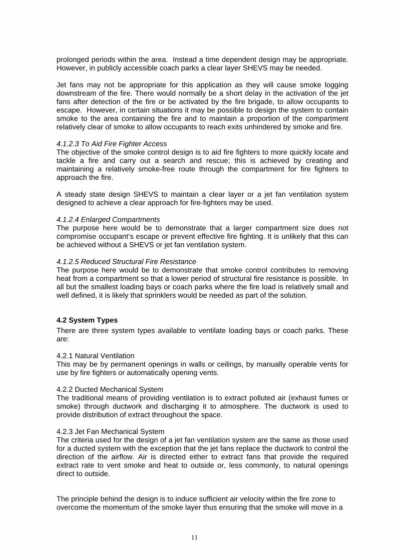
prolonged periods within the area. Instead a time dependent design may be appropriate. However, in publicly accessible coach parks a clear layer SHEVS may be needed. Jet fans may not be appropriate for this application as they will cause smoke logging downstream of the fire. There would normally be a short delay in the activation of the jet fans after detection of the fire or be activated by the fire brigade, to allow occupants to escape. However, in certain situations it may be possible to design the system to contain smoke to the area containing the fire and to maintain a proportion of the compartment relatively clear of smoke to allow occupants to reach exits unhindered by smoke and fire. 4.1.2.3 To Aid Fire Fighter Access The objective of the smoke control design is to aid fire fighters to more quickly locate and tackle a fire and carry out a search and rescue; this is achieved by creating and maintaining a relatively smoke-free route through the compartment for fire fighters to approach the fire. A steady state design SHEVS to maintain a clear layer or a jet fan ventilation system designed to achieve a clear approach for fire-fighters may be used. 4.1.2.4 Enlarged Compartments The purpose here would be to demonstrate that a larger compartment size does not compromise occupant’s escape or prevent effective fire fighting. It is unlikely that this can be achieved without a SHEVS or jet fan ventilation system. 4.1.2.5 Reduced Structural Fire Resistance The purpose here would be to demonstrate that smoke control contributes to removing heat from a compartment so that a lower period of structural fire resistance is possible. In all but the smallest loading bays or coach parks where the fire load is relatively small and well defined, it is likely that sprinklers would be needed as part of the solution.
4.2 System Types There are three system types available to ventilate loading bays or coach parks. These are: 4.2.1 Natural Ventilation This may be by permanent openings in walls or ceilings, by manually operable vents for use by fire fighters or automatically opening vents. 4.2.2 Ducted Mechanical System The traditional means of providing ventilation is to extract polluted air (exhaust fumes or smoke) through ductwork and discharging it to atmosphere. The ductwork is used to provide distribution of extract throughout the space. 4.2.3 Jet Fan Mechanical System The criteria used for the design of a jet fan ventilation system are the same as those used for a ducted system with the exception that the jet fans replace the ductwork to control the direction of the airflow. Air is directed either to extract fans that provide the required extract rate to vent smoke and heat to outside or, less commonly, to natural openings direct to outside. The principle behind the design is to induce sufficient air velocity within the fire zone to overcome the momentum of the smoke layer thus ensuring that the smoke will move in a

12
particular direction. The positioning and number of jet fans used must take into account the layout of the space and consideration must be given to a number of factors. Firstly, the fire size and height of rise of the smoke to the ceiling will influence the energy in the ceiling jet and therefore the velocity required to prevent backlayering. Secondly, a number of additional factors that will influence the performance of the fans, these include:
• Floor to soffit height • Beams, downstands, columns, lighting cable trays, signage, and other physical
obstructions • Vehicle size and positions • Other air currents/patterns in the space, created for example by incoming air from
inlet openings • Building shape and stair cores
Where a sprinkler system is to be installed, the location of the sprinkler heads and jet fans shall be co-ordinated to ensure that the effect of the jet fans on the spray pattern of the sprinklers is minimized. Care shall be taken to ensure that the number of jet fans activated will not induce the movement of a volume of air greater than that which the main extract fans are capable of extracting.

13
5 Smoke Clearance Systems
5.1 General Guidance The objective of the smoke clearance system is to:
a. Help dilute the smoke and reduce the temperature during the course of a fire. b. Assist fire-fighters by providing ventilation to allow clearance of the smoke once
the fire has been extinguished; This system is not specifically intended to maintain any area clear of smoke, nor to limit smoke density or temperature to within any specific limits or to assist means of escape. Therefore, there are no tenability criteria provided for this system. However, guidance on vent areas and extract rates is given in regulatory documents and summarised below.
Given the anticipated large fires the system shall ideally be initiated as soon as practical after a fire is detected. However, it is possible that Jet Fan systems, if set in operation too early, might actually worsen conditions for means of escape by encouraging smoke circulation and descent of the smoke layer – see section 5.4. Other ventilation systems shall shut down to prevent movement of smoke to unaffected areas of the building. The discharge points for the smoke exhaust system shall be located such that they do not cause smoke to be recirculated into the building, spread to adjoining buildings, or adversely affect the means of escape. They shall be located so that inlet air is not drawn immediately into the extract system rather than smoke. The BS EN 12101 series provides advice on the performance of smoke control equipment. In particular, all fans intended to exhaust hot gases shall be tested in accordance with BS EN 12101 – 3 to verify their suitability for operating at 300o C for a period not less than 60 minutes (class F300). Where the main extract fans are located within the building, but outside the fire compartment which they serve, they shall be enclosed with elements of structure having a fire resistance at least equal to that required for compartmentation between the different parts of the building through which it passes. Ductwork, dampers, and fixings shall conform to Section 9.2.
5.2 Natural Ventilation for Smoke Clearance Guidance on smoke ventilation of car parks and basements recommends that 2.5% of the net floor area of the compartment must be available in openings directly to atmosphere, either in the walls and arranged to allow cross flow, or in the ceiling. Openings would normally need to be distributed evenly around the perimeter. Given the possibility of larger fires in service yards, loading bays and coach parks, the designer should give information on how the design objectives will be met. The design engineer should be able to justify that the available openings will be adequate to provide sufficient ventilation to meet the design objective. Compliance with Building Regulations guidance is one way. Another way in which this could be achieved is by the use of CFD modelling. (see section 11).

14
5.3 Ducted Mechanical Systems for Smoke Clearance This system would normally meet the requirements of the current building regulations by providing 6 air changes per hour under day to day ventilation conditions and 10 air changes per hour under fire conditions within each fire compartment served by that system. Sprinklers would normally be needed to ensure that the smoke temperatures do not cause failure of the system and impede fire growth. When deviating from Building Regulations guidance, the design engineer shall be able to justify that the alternative design will be adequate to provide sufficient ventilation to meet the design objective. One way in which this could be achieved is by the use of CFD modelling (see section 11). The system shall be independent from any other system (other than any other system providing normal ventilation to the compartment) and be designed to operate at 10 air changes per hour. Where part of a dual fume and smoke clearance system the extract points shall be arranged so that 50% of the exhaust capacity is at high level and 50% is at low level and evenly distributed over the whole compartment. The main extract system shall be designed to run in at least two parts, such that the total exhaust capacity does not fall below 50% of the rates required in the event of failure of any one part and shall be such that a fault or failure in one will not jeopardize the others. The system shall have a maintained power supply, designed to operate in the event of failure of the main power supply. The fans and associated control equipment shall be wired in protected circuits designed to ensure continued operation in the event of a fire. Care shall be taken to ensure that there are no stagnant areas in either daily ventilation or smoke ventilation operational mode. Provision shall be made for the supply of replacement air to the compartment. Care should be taken to ensure correct distribution of air inlets in relation to the extract point(s) to avoid short circuiting. The velocity of air along ramps and vehicle entrances shall not exceed 5 m/s in order to avoid impeding the escape of occupants from the building.
5.4 Jet Fans for Smoke Clearance When considering the use of a jet fan system, consideration should be given to how efficient the jet fans will be in achieving air movement at low level as well as high level due to the height of the space and the obstruction caused by larger vehicles. The main extract fans shall normally operate immediately on confirmation of a fire to provide the required extract rate. After an appropriate delay, the jet fans shall activate in such numbers as necessary to direct the smoke effectively towards the main extract points.
15
The delay in the activation of the jet fans may be necessary to ensure that escaping occupants are not compromised by the action of the jet fan system. The system shall be designed so that escaping occupants can walk to a storey exit such that they are not inhibited by the smoke and heat generated by the fire and moved by the fans operating during the initial escape period. The delay employed to achieve this outcome will depend on one or more factors, e.g.:
• The size and geometry of the compartment; • The number and location of extract and jet fans; • The number and type of occupants; and • The number and location of suitable exits.
The delay period, if any, shall be confirmed in agreement with the approving authorities. Consideration shall be given to the location of the means of escape when locating the position of the extract point(s). The position of stairwells, means of escape corridors, and lobby doors, where present, shall be co-ordinated with jet fan locations and jet orientations to avoid exposing the doors to dynamic pressure effects which might cause smoke to enter the lobby, stairwell and/or corridors. Care shall be taken to ensure that there are no stagnant areas in either daily ventilation or smoke ventilation operational mode. Adequate provision shall be made for the supply of replacement air. The velocity of air along ramps and vehicle entrances shall not exceed 5 m/s in order to avoid impeding the escape of occupants from the building. The system shall be independent from any other system (other than any system providing normal ventilation). The main extract system shall be designed to run in at least two parts, such that the total exhaust capacity does not fall below 50% of the rates set out in above in the event of failure of any one part and shall be such that a fault or failure in one will not jeopardize the other Each part of the main extract system and the jet fans shall have a maintained independent power supply, which will operate in the event of failure of the main power supply. The fans and associated control equipment shall be wired in protected circuits designed to ensure continued operation in the event of a fire (see Section 9).
16
6 Smoke Control Systems 6.1 Design Objectives The aim of a smoke control system is to remove heat and smoke from the compartment to meet the design objectives as determined by one of the options given in Section 4.1. The system is to provide tenable conditions within the compartment, or to contain smoke within a predetermined area and extract it to atmosphere. The design shall be based on calculation, and shall be based on the performance criteria given in the relevant sections below. For the purpose of this document two smoke control systems are considered:
1. SHEVS (Smoke and Heat Exhaust Ventilation Systems), which are designed to maintain tenable conditions within smoke or a clear layer beneath it
2. Jet Fan systems which are used to direct smoke to extract points or away from areas of the building, but which are not expected to maintain tenable conditions within the smoke.
The system will be designed to maintain tenable conditions on escape routes when designing to aid means of escape (Section 4.1.2.2), which may require a clear layer. For other options (Sections 4.1.2.3, 4.1.2.4, 4.1.2.5) a smoke clear layer is likely to be needed, but alternatives may be possible. The performance criteria can be different for each option, for example, the minimum clear height can be different for occupant’s escape and for fire fighting, in view of the protective clothing and training available for fire-fighters. BS7346 Part 4 and BS 7974 give recommendations for smoke clear layers and tenability criteria where the SHEVS is to protect escape routes for employees and the public. Where the SHEVS is designed to provide a clear, smoke-free approach to the fire for fire-fighters, the clear layer height shall be at least 1.75m. In the design of a smoke control system in loading bays and coach parks particular consideration should be given to the following:
• The geometry of the building • Downstand beams • Obstruction by large vehicles • Height of the compartment • Achieving low level air movement • Interference with sprinkler activation and pattern • Excessive smoke temperatures affecting fan integrity
6.2 Design Criteria Notwithstanding the requirements for daily ventilation, on confirmation of a fire the main extract fans, where present, shall operate automatically to provide the required rate of extract within the compartment. It is important to ensure that the rate of extract is sufficient to meet the design objectives. For this purpose, the fire load used in the design calculations shall be compatible with the fire sizes outlined in this document, (see section 7.2.2), as a notional volumetric air

17
change rate may not be appropriate. If the SHEVS can meet the airflow requirements for vehicle exhaust emission control with a reduced volume flow rate compared to the requirements for smoke control, it might be used to fulfil both sets of requirements. The design of the SHEVS shall follow the smoke control guidance documents, with certain exceptions specific to loading bays and coach parks in a) to g):
a) The design fire, whether steady-state or time dependent, shall be based on Section 7.2.2, or another justifiable alternative.
b) Where the system is shared with any other ventilation or HVAC system in the building it must be designed to prevent the spread of smoke and flame to other areas of the building.
c) To ensure through-flow of smoke and heat through the vents, inlet air will be needed at low level beneath the design smoke layer. Permanent openings or automatically opening inlets shall be provided.
d) Inlets shall conform to the recommendations of BS 7346-4, and where the vehicle entrances and/or exits are required for the smoke control system the system shall ensure that any gates are automatically opened to provide exhaust or inlet.
e) Automatically opening inlets for replacement air shall be large enough (if natural openings) or shall be sufficiently extensive and evenly distributed (if air is supplied by fans via ducts) to ensure that the airspeed in the incoming jets formed inside the inlets does not cause a recirculation of smoke.
f) Inlet air provision shall be designed to ensure that it does not disturb the smoke layer. The maximum inlet air speed shall be 2 m/s, unless it can be demonstrated that higher velocities do not disturb the smoke layer.
g) Additionally, the velocity of air on ramps and vehicle entrances shall not exceed 5 m/s in order to avoid impeding the escape of occupants of the building.
Other ventilation systems shall shut down to prevent movement of smoke to unaffected areas of the building.
6.3 Natural SHEVS Ventilation will usually be by a mixture of permanently open vents or automatically opening vents. It is unlikely that manually operable vents will be appropriate. Care shall be taken to ensure that the relationship between ventilator area and aerodynamic performance is understood and considered in the design. The Approved Document B, the BS 7346 series and BS EN 12101-2 shall be consulted for calculation procedures and the methods of determining the performance of ventilators.
6.4 Recommendations Common to Mechanical Smoke Control Systems In all cases there shall be standby capacity of the main extract fans to maintain the design extract rate assuming failure of one fan. The system can be shared with that used for fume ventilation, although the extract rate may need to increase to deal with the larger volumes of smoke. The system shall extract only at high level when used to extract smoke, and any low level extract shall either shut down or operate to provide inlet air. The extract rate shall be achieved within the compartment. Therefore, the system shall be designed to allow for pressure losses within the extract system between the compartment and the fans and from the fans to outside.
18
Ducting, dampers and fans shall be rated in accordance with the recommendations given in the relevant section 9.2 of this guide, and at the temperatures specified as part of the design criteria.
6.5 Ducted Mechanical SHEVS For a mechanical SHEVS ducting shall be provided to extract smoke and heat from high level and be linked to at least two extract fans (duty/standby).
6.6 Jet Fans for Smoke Control 6.6.1 Design Principles The extract rate shall be calculated for the removal of the mass of mixed air and smoke impelled towards the exhaust intakes. The number of jet fans activated shall not cause the volume of air movement to be greater than the volume extracted by the main extract fans. All supporting calculations and justifications shall be fully documented. The effect of the system on all other areas of the building shall be considered. Areas, other than the one where the fire is located, should be kept substantially free of smoke. The position of the stairwells, means of escape corridors, and lobby doors, where present, shall be co-ordinated with jet fan locations and jet orientations to avoid exposing the doors to dynamic pressure effects which might cause smoke to enter the lobby, stairwell and/or corridors. The distribution of the jet fans shall be such that there are no stagnant areas in daily ventilation operational mode. The ventilation system shall be able to control the flow of smoke wherever the fire occurs within the compartment. The design objectives of the system shall be met even after failure of the jet fan closest to the fire. In large compartments it may be possible to design the system so that smoke is largely confined to within specific areas by the action of the jet fans. Designs based on the creation of these smoke control zones shall either:
• Have physical partitions to create channels for the smoke and the induced air flow, thus separating neighbouring zones; or
• Demonstrate, using a CFD model conforming to the Smoke Control Association
Guide for CFD modelling of Car Parks, Loading Bays and Coach Parks, that smoke is contained within the zone boundaries, is channelled to the extract fans, and does not lead to untenable conditions being created due to significant quantities of smoke to circulate in other zones
On detection of a fire, the main extract fans shall operate to provide the calculated rate of extract for a fire condition. After an appropriate delay, the jet fans shall activate in such numbers as necessary to direct the smoke efficiently towards the main extract points for a fire condition.
19
The delay is necessary to ensure that the escaping occupants are not compromised by the action of the jet fan system. Within the affected smoke zone, escaping occupants need to be able to walk to a clear storey exit such that they are not inhibited by the smoke and heat generated by the fire and moved by the fans operating during the initial escape period. The delay employed to achieve this outcome will depend on one or more factors, eg:
• The size and geometry of the compartment • The number and size of smoke zones • The number and location of extract and jet fans • The numbers and type of occupants • The number and location of suitable exits
The delay shall be based on a fire engineering methodology and show that the available safe escape time from the affected smoke zone is greater than the required safe escape time plus a suitable safety margin. The delay periods, if any, shall be confirmed in agreement with the approving authorities. The aerodynamic performance of the jet fan shall be tested in accordance with BS 848-10 or an appropriate European Standard. 6.6.2 Jet Fans to Protect Means of Escape The objective of the system is to provide protection of escape routes for occupants within the compartment on fire, to preserve tenable conditions on escape routes to either the exterior of the building or to a protected stairwell or corridor which leads to a final exit to a place of safety. Care shall be taken to ensure that routes for access to a point of escape are not compromised due to poor visibility. The following recommendations are made due to the potential for jet fan systems to cause smoke logging of areas downstream of the fire.
• Where the compartment is divided into smoke zones there shall be a sufficient number of exit doors/escape routes unaffected by smoke for the estimated population in the compartment to evacuate safely with all exits in the extract direction in the affected smoke zone discounted
• The design shall show that the available safe escape time from the affected smoke zone is greater than the required safe escape time plus a suitable safety margin.
6.6.3 Jet Fans to Aid Fire Fighter Access There shall be fire-fighter access (from the exterior, or from protected stairwells) to the compartment, positioned to allow fire-fighters to have at least one relatively clear approach route to any possible fire location.
Information as to the zone in which the fire has occurred shall be automatically displayed at an appropriate location. A map of access points to the loading bay or coach park shall also be provided to enable fire fighters to assess the most appropriate route to approach the fire. The intention of the system is to aid fire fighters to locate the fire and approach to within a distance to allow fire hoses to be directed onto the fire. However, fires in loading bays and coach parks are potentially far larger than those in car parks. Unlike in car parks it may not possible to ensure that fire fighters can move through substantially smoke-free air when approaching the fire up to a distance of 10m from that fire.

20
Therefore, the acceptance criteria will need to be agreed with the local Fire Authority, recognising that the primary aim is to allow fire fighters to locate the fire and fight it more easily compared to a fire in a building without a smoke control system. 6.6.4 Jet Fans for Enlarged Compartments and Reduced Structural Fire Resistance The objective of the system is to limit the extent to which heat and smoke affect structure or other areas of the building. It is likely that a design to aid fire fighter access will also be part of the solution. The recommendations given in section 6.6.3 when designing to aid fire fighter access shall be followed.
21
7. Smoke Control Design Criteria
7.1 Use of Design Fires When designing a smoke clearance system strictly in accordance with Building Regulations guidance there shall be no need to consider a design fire. This assumes that the designer has followed the guidance for compartmentation, means of escape and fire fighting access, supported by smoke extract and sprinklers where recommended. This would normally provide an adequate standard of safety. When designing for a smoke control system, a design fire size needs to be specified.
7.2 Design Considerations
7.2.1 Sprinklers Smoke control alone may be enough to aid fire fighting in small loading bays and service yards. In larger compartments where there are large permanent openings to outside, the openings alone may be sufficient for smoke venting without sprinklers. However, in enclosed loading bays, service yards and coach parks sprinklers are likely to be needed to prevent fire spread involving the entire compartment. Due to the weatherproof nature of the vehicles involved, the effect of sprinklers may be limited to a reduction in smoke temperatures, particularly during the early stages of the fire, and to limiting fire spread to adjacent vehicles. Consideration shall be given to the direction of the floor slope in the loading bay as this may influence potential fire spread, particularly when there is a scenario of oil based fuels (or fuels that change state) being present (drainage causing floating fuel to be moved) Consideration shall be given to the effect of sprinkler cooling on the smoke, as sprinkler spray will reduce the smoke temperature. When using mechanical extract ignoring the effect will produce a conservative design. For natural ventilation systems sprinkler cooling may need to be considered as it will reduce the buoyancy of smoke and reduce the effectiveness of natural vents. See also Section 8.
7.2.2 Vehicle Design Fire Size BS 7346-7 gives guidance for the provision of smoke control systems for car parks and provides design fire sizes for sprinklered and unsprinklered car fires. In loading bays, service yards and coach parks, where the main fire source is likely to be vans, lorries and coaches, the potential fire load for design purposes is considerably greater. While there is considerable research in this area for tunnel fires, there is little agreement on what the maximum potential fire size might be. It is recognised in many guidance documents for tunnels for example, that although the potential fire size may be much larger than those specified, once the fire has developed beyond a certain size there is little further benefit that can be achieved by a smoke control system. In that case an appropriate sprinkler system will be the primary means of controlling fire growth. Sprinklers will prevent or at least delay further fire spread.
22
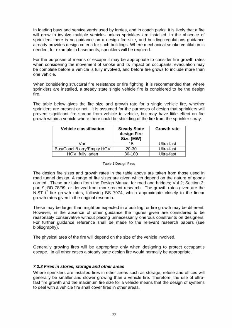
In loading bays and service yards used by lorries, and in coach parks, it is likely that a fire will grow to involve multiple vehicles unless sprinklers are installed. In the absence of sprinklers there is no guidance on a design fire size, and building regulations guidance already provides design criteria for such buildings. Where mechanical smoke ventilation is needed, for example in basements, sprinklers will be required. For the purposes of means of escape it may be appropriate to consider fire growth rates when considering the movement of smoke and its impact on occupants; evacuation may be complete before a vehicle is fully involved, and before fire grows to include more than one vehicle. When considering structural fire resistance or fire fighting, it is recommended that, where sprinklers are installed, a steady state single vehicle fire is considered to be the design fire. The table below gives the fire size and growth rate for a single vehicle fire, whether sprinklers are present or not. It is assumed for the purposes of design that sprinklers will prevent significant fire spread from vehicle to vehicle, but may have little effect on fire growth within a vehicle where there could be shielding of the fire from the sprinkler spray.
Vehicle classification Steady State design Fire Size (MW)
Growth rate
Van 15 Ultra-fast Bus/Coach/Lorry/Empty HGV 20-30 Ultra-fast
HGV, fully laden 30-100 Ultra-fast
Table 1 Design Fires The design fire sizes and growth rates in the table above are taken from those used in road tunnel design. A range of fire sizes are given which depend on the nature of goods carried. These are taken from the Design Manual for road and bridges; Vol 2; Section 3; part 9; BD 78/99, or derived from more recent research. The growth rates given are the NIST t2 fire growth rates, following BS 7974, which approximate closely to the linear growth rates given in the original research. These may be larger than might be expected in a building, or fire growth may be different. However, in the absence of other guidance the figures given are considered to be reasonably conservative without placing unnecessarily onerous constraints on designers. For further guidance reference shall be made to the relevant research papers (see bibliography). The physical area of the fire will depend on the size of the vehicle involved. Generally growing fires will be appropriate only when designing to protect occupant’s escape. In all other cases a steady state design fire would normally be appropriate.
7.2.3 Fires in stores, storage and other areas Where sprinklers are installed fires in other areas such as storage, refuse and offices will generally be smaller and slower growing than a vehicle fire. Therefore, the use of ultra-fast fire growth and the maximum fire size for a vehicle means that the design of systems to deal with a vehicle fire shall cover fires in other areas.

23
If sprinklers are not installed or the other areas form separate compartments then reference shall be made to other guidance for determining design fire size and growth rates. The following will then need to be taken into consideration:
• The type of combustible materials stored • The amount and disposition of the fire load • The degree of fire resisting enclosure.

24
8. Sprinklers The design requirements for sprinkler protection of buildings are defined in BS EN 12845:2004 / LPC Rules for Automatic Sprinkler Installations. The fire protection requirements for industrial and storage buildings are normally determined by the anticipated fire load involved, along with the processes of manufacturing or the type, height and method of storing goods. Depots for Buses, un-laden Lorries and Railway Carriages are considered as a High Hazard 2 process risk under BS 12845:2004 / LPC Rules for Automatic Sprinkler Installations. The requirements for laden Lorries are not specified and it is therefore essential that the sprinkler system is designed by a suitably qualified and experienced sprinkler engineer. When designing a sprinkler system for a loading bay or a coach park, the factors that the sprinkler engineer are likely to consider, include, but are not limited to the following:
• The number and size of vehicles likely to be present. • The type and height of stacked goods carried on vehicles. • The likelihood of additional stored goods being present in the vicinity of vehicles. • Parking arrangements and the potential for fire spread between vehicles. • The most effective sprinkler head spacing with respect to the parking
arrangements; so as to limit fire spread from vehicle to vehicle. • The assumed maximum area of operation, design density of the sprinkler system
and relevant water storage requirements. • The interaction between the ventilation and sprinkler systems. • Ceiling height
25
9 System Components
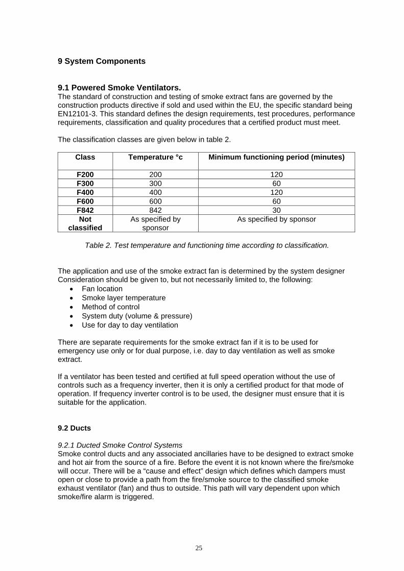
9.1 Powered Smoke Ventilators. The standard of construction and testing of smoke extract fans are governed by the construction products directive if sold and used within the EU, the specific standard being EN12101-3. This standard defines the design requirements, test procedures, performance requirements, classification and quality procedures that a certified product must meet. The classification classes are given below in table 2.
Class Temperature °c Minimum functioning period (minutes)
F200 200 120 F300 300 60 F400 400 120 F600 600 60 F842 842 30 Not
classified As specified by
sponsor As specified by sponsor
Table 2. Test temperature and functioning time according to classification.
The application and use of the smoke extract fan is determined by the system designer Consideration should be given to, but not necessarily limited to, the following:
• Fan location • Smoke layer temperature • Method of control • System duty (volume & pressure) • Use for day to day ventilation
There are separate requirements for the smoke extract fan if it is to be used for emergency use only or for dual purpose, i.e. day to day ventilation as well as smoke extract. If a ventilator has been tested and certified at full speed operation without the use of controls such as a frequency inverter, then it is only a certified product for that mode of operation. If frequency inverter control is to be used, the designer must ensure that it is suitable for the application. 9.2 Ducts 9.2.1 Ducted Smoke Control Systems Smoke control ducts and any associated ancillaries have to be designed to extract smoke and hot air from the source of a fire. Before the event it is not known where the fire/smoke will occur. There will be a “cause and effect” design which defines which dampers must open or close to provide a path from the fire/smoke source to the classified smoke exhaust ventilator (fan) and thus to outside. This path will vary dependent upon which smoke/fire alarm is triggered.

26
The damper at the fire/smoke location must be open to allow the smoke/heat to be extracted. Any dampers in the extract route must also be fully open (for the least pressure drop/greater volume) to complete that route. Any dampers that isolate spurs or are directly isolating the route (e.g. on the surface of the duct) must be closed. As the damper at the fire/smoke location will be open, the duct now forming the extract path has become part of the fire compartment from which smoke is being extracted. Therefore that duct and any associated dampers, not in the direct path, have to be fire resisting maintaining compartmentation along that path. Conversely all the open dampers have to be proven in their ability to maintain their opening, and their ability to keep the path clear. The ductwork needs to maintain cross-sectional area during an incident, so that increased pressure drop does not occur resulting in a reduced extract rate. To achieve this flexibility, smoke control dampers shall be under the control of a system, that responds to fire or smoke signals. This means that dampers shall be actuated. Spring return actuators shall not be used and fusible links shall not be used, rather tested drive open/drive closed actuators. It is not possible to outguess where a fire will occur. If spring return dampers are used, and during the incident the power fails, the dampers will change state. If closed dampers near to the fan open incorrectly, air would then be drawn from them, rather than from where it is needed. If a damper in the line closed incorrectly extract would simply stop from where it is needed. The designer must take account of potential failure modes during design process and assess the risks associated with potential failures. If balancing is required, this may be achieved by modulating drive open/drive closed actuators responding to a control signal for set point, but with the ability for this to be overridden to drive fully open or fully closed in the event of fire/smoke alarm. If un-motorised balancing dampers are to be used, they shall be modified versions of the tested smoke control dampers to maintain duct integrity and any modifications made must be within the parameters set in the test code. The system designer needs to ensure that any fans are capable of drawing the required extract volumes through these partially closed units and their associated additional pressure drop. Existing British Standards make a requirement for smoke control ducts to have a known performance at 600°C, ancillaries to have proven performance to 300°C; however, no ducting shall compromise compartmentation. It may be seen that to extract smoke from a specific area there is a great likelihood that the duct will cross many compartments and so in most cases will need to be fire resisting. 9.2.2 Single compartment smoke control duct sections Where smoke control ductwork does not need to be fire resisting (i.e. does not maintain compartmentation), smoke control duct sections can be tested to 600°C. The following are the CEN product standard (certification and CE marking), test standard and classification standards respectively.
prEN 12101-7: Smoke and heat exhaust ventilation – Part 7: Smoke control duct sections BS EN 1366-9: Fire resistance tests for service installations: Smoke extraction ducts (single compartment) BS EN 13501-4: Fire classification of construction products and building elements - part 4: classification using data from fire resistance tests on components of smoke control systems
27
As an alternative, where such products may not be readily available, any duct tested as fire resisting could meet this requirement, as these tests are made using the standard time time/temperature curve – these test standards are as follows:
BS 476-24: Fire tests on building materials and structures – part 24: Method for the determination of the fire resistance of ventilation ducts BS EN 1366-1: Fire resistance tests for service installations: Ducts BS EN 1366-8: Fire resistance tests for service installations: Smoke extraction ducts (multi compartment) Note: Although in the first two instances no specific limits are made with respect to loss of cross-sectional area, BS476-24 includes this as an additional observation, so careful examination of test reports shall be made.
If the transition between single compartment smoke control duct and multi-compartment smoke control duct takes place inside the final single compartment at a safe distance from the compartment boundary (protection by fire resisting ductwork), no damper protection would be needed. If the transition takes place at the boundary a multi-compartment smoke control damper shall be installed (not a fire damper). 9.2.3 Multi compartment smoke control duct sections Where smoke control ductwork needs to be fire resisting (i.e. needs to maintain compartmentation), smoke control duct sections can be tested to the standard/time temperature curve, making them fire resisting. The following are the CEN product standard (certification and CE marking), test standard and classification standards respectively.
prEN 12101-7: Smoke and heat exhaust ventilation – Part 7: Smoke control duct sections BS EN 1366-8: Fire resistance tests for service installations: Smoke extraction ducts (multi compartment) BS EN 13501-4: Fire classification of construction products and building elements - part 4: classification using data from fire resistance tests on components of smoke control systems
As an alternative, where such products may not be readily available, any duct tested as fire resisting could meet this requirement, as these tests are made using the standard time time/temperature curve – these test standards are as follows
BS 476-24: Fire tests on building materials and structures – part 24: Method for the determination of the fire resistance of ventilation ducts BS EN 1366-1: Fire resistance tests for service installations: Ducts Note: Although in these instances no specific limits are made with respect to loss of cross-sectional area, BS476-24 includes this as an additional observation, so careful examination of test reports shall be made.
9.3 Dampers 9.3.1 Single compartment smoke control dampers Where smoke control dampers do not need to be fire resisting (i.e. does not maintain compartmentation), smoke control dampers can be tested to 600°C. The following are the CEN product standard (certification and CE marking), test standard and classification standards respectively.

28
prEN 12101-8: Smoke and heat exhaust ventilation – Part 7: Smoke control dampers prEN 1366-10: Fire resistance tests for service installations: Smoke control dampers BS EN 13501-4: Fire classification of construction products and building elements - part 4: classification using data from fire resistance tests on components of smoke control systems Note 1: Automatic control – the above standards state that for the application of smoke control dampers under automatic control of a smoke control system working directly from fire or smoke sensor inputs must be proven by test to shut (and open) within 60 seconds, having been actuated 30 seconds after the start of the test. They shall be tested at the same time as the smoke control damper as part of the assembly. Note 2: Manual intervention - the above standards state that for the application of smoke control dampers under the control of a system that is required to be started by someone, or someone is expecting to have control of smoke control dampers during the incident, must be proven by test to shut (and open) within 60 seconds, having been actuated 25 minutes after the start of the test. They shall be tested at the same time as the smoke control damper as part of the assembly.
As an alternative, where such products may not be readily available, any damper tested as fire resisting (tests are made using the standard time time/temperature curve), supported by an ad hoc operation test at elevated temperature (e.g. 300° and/or 600°C for 1 hour etc) using a drive open/drive close actuator could meet this requirement, these test standards are as follows
BS EN 1366-2: Fire resistance tests for service installations: Fire dampers - plus ad hoc test report 300° and/or 600°C for 1 hour etc Note: The above does not consider the loss of cross-sectional area of an open damper prEN 1366-10: Fire resistance tests for service installations: Smoke control dampers Note: If a smoke control damper is tested to the requirements of the latter for multi-compartment applications (using the fire test curve), it is automatically allowed to apply to single compartment applications
9.3.2 Multi compartment smoke control dampers Where smoke control dampers need to be fire resisting (i.e. need to maintain compartmentation), smoke control dampers can be tested to the standard/time temperature curve, making them fire resisting. The following are the CEN product standard (certification and CE marking), test standard and classification standards respectively.
prEN 12101-8: Smoke and heat exhaust ventilation – Part 7: Smoke control dampers prEN 1366-10: Fire resistance tests for service installations: Smoke control dampers BS EN 13501-4: Fire classification of construction products and building elements - part 4: classification using data from fire resistance tests on components of smoke control systems Note 1: Automatic control – the above standards state that for the application of smoke control dampers under automatic control of a smoke control system working directly from fire or smoke sensor inputs must be proven by test to shut (and open) within 60 seconds, having been actuated 30 seconds after the start of
29
the test. They shall be tested at the same time as the smoke control damper as part of the assembly. Note 2: Manual intervention - the above standards state that for the application of smoke control dampers under the control of a system that is required to be started by someone, or someone is expecting to have control of smoke control dampers during the incident, must be proven by test to shut (and open) within 60 seconds, having been actuated 25 minutes after the start of the test. They shall be tested at the same time as the smoke control damper as part of the assembly.
As an alternative, where such products may not be readily available, any damper tested as fire resisting (tests are made using the standard time time/temperature curve), supported by an ad hoc operation test at elevated temperature (e.g. 300° and/or 600°C for 1 hour etc) using a drive open/drive close actuator could meet this requirement, – these test standards are as follows
BS EN 1366-2: Fire resistance tests for service installations: Fire dampers - plus ad hoc test report 300° and/or 600°C for 1 hour etc Note: The above does not consider the loss of cross-sectional area of an open damper BS EN 1366-2: Fire resistance tests for service installations: Fire dampers - plus modified HOT400/30 test from prEN1366-10 using 300° and/or 600°C for 1 hour etc Note: The latter above is an acceptable test to prEN1366-10, if the 400°C test is undertaken for 30 minutes anyway
Any proposed designs shall be presented to building control authorities supported with the necessary tests and reasoning.

30
10. Controls & Power Supplies 10 Controls - General The nature of the system should be that under quiescent conditions the control equipment should be in either fully automatic or standby mode. In this mode the control equipment must be protected against improper use. 10.1 Control Panels Control Panels should comply with prEN12101-9. Consideration should be given to the location of control panels and control equipment. Most control panels complying with prEN12101-9 are only designed to operate at ambient temperatures. Therefore they should be located such that the risk of exposure to high temperatures is minimised (located separately from the fire compartment by a fire-resisting separation of at least 1 hour). 10.2 Manual Control Point prEN12101-9 sets out the operational and aesthetic requirements for a manual control point. The term “manual control point” is designed to encompass generic phrases such as fireman’s switch, call point, breakglass etc. Under prEN12101-9 the manual control point requires the manual control point to be deep orange to RAL 2011. Manual Control Points shall be provided at agreed fire service access points. For automatic systems the switches shall provide off/auto control and where appropriate off/auto/on control. For manual systems the switches shall provide off/on control. 10.3 System Activation Where permanent openings are not used the system shall be initiated by one or more of the following:
a. Smoke detection; b. Rapid rate of rise heat detection; c. Multi-criteria fire detection; d. A sprinkler flow switch; e. A fire service action, such as a control switch or in the case of natural ventilation the
use of breakout panels, pavement lights, stallboards and the like.
All mechanical systems shall have a fire service override switch to allow them to turn on or turn off the system. Fire service action is not suitable as the only form of initiation for smoke control systems designed to assist fire-fighting access and/or protect means of escape. Operation in the case of a fire shall override any environmental controls associated with the smoke and heat control system for controlling the normal environmental ventilation arrangements for the loading bay, if fitted.

31
The installation of a smoke, rapid rate of rise heat, or multi criteria detection system shall conform to the requirements of BS 5839: Part 1. The type and location of detectors shall be selected to initiate operation of the system as early as possible. The detectors shall be located to minimise adverse effects from air movement caused by the environmental ventilation system. In some situations a delay may be built into the operating system to hold off operation of all or part of the system for a set period see sections 5.4 & 6.6 Where zoned control is required, the detection system shall be addressable and capable of locating the fire with an accuracy that allows the different zones of the smoke and heat control system to operate appropriately within the design. 10.4 Power Supplies There shall be at least two power sources: the primary power source and the secondary power source. The primary power source shall be designed to operate from the public electricity supply or an equivalent system. The secondary power source, for example batteries, generator or a secondary independent public utilities supply, shall be permanently available, tested and maintained. Each power source, on its own, shall be capable of operating those parts of the system for which it is intended. If the primary power source fails, then the power supply shall be automatically switched over to a secondary power source. Failure of one of the power sources shall not cause the failure of any other power source or the failure of the supply of power to the system. The power supply equipment shall either have inherent resistance to or be protected from mechanical damage. The power supply and related equipment shall be clearly labelled as to their purpose and be secured against unauthorised operation.
Each power supply should provide the power requirements of the worst case scenario at design duty under ambient conditions.
The power supplies to each component(s) should be protected against the effects of fire for the required period of time of activation or operation of the component(s).
Electrical power for smoke ventilation fans can be provided by either:
2 independent electrical public utility supplies, or
1 electrical public utility supply and backup power supply (generating plant).
Power supplies should be installed such that they remain operational when other supplies to the building are isolated in an emergency.
All electrical services shall be installed by suitably qualified engineers in accordance with BS 7671:1992 (IEE Wiring Regulations). The electrical primary power supply to life safety and fire protection ventilation equipment shall be separate from all other circuits in the building so that the failure of other equipment does not render the installation inoperative.
32
Each connection to the power supply shall be via an isolating protective device reserved solely for life safety and fire protection equipment and independent of any other main or sub-main circuit. Such isolating protective devices shall be clearly labelled and identified as to their purpose. They shall be secured against unauthorized operation. The primary and secondary power sources, electrical distribution board, cables and control equipment supplying power to the fire-fighting equipment shall be protected against fire and water damage for a period of at least 1 hour. They shall be kept separate so that a failure in a cable or equipment, either by mechanical breakdown or damage by fire, in either supply does not affect the other supply. Protection against fire can be achieved through choice of cable, the cable route (e.g. through protected areas, or external to the building) or by the use of a fire-resisting construction. The primary and secondary power supply cables shall be terminated in a changeover device located within the fire resistant compartment housing the main control panel. The changeover device shall automatically effect a transition from the primary to the secondary power supply if any phase of the primary power supply fails. Whichever secondary source is provided, the distribution shall be organised such that the secondary supply remains live when the remainder of the supplies in the building are isolated in an emergency. All electrical wiring, actuators, control equipment shall be protected against fire, when the effects of fire will result in the failure or incorrect operation of the vents/damper/doors for the appropriate period of time. The cables for the power supplies shall comply with one of the following British Standards:- • BS 8519: Selection and Installation of Fire Resistant power and control systems for life
safety and fire-fighting applications • BS 8434: Part 3 for fire fighting systems • BS 5839: Part 1 for Means of Escape systems The electrical cables and associated equipment shall be sized and fitted in accordance with manufacturer’s instructions.
All electrical wiring shall be clearly labeled and identified. 10.5 Cabling & Areas of Special Risk BS 8519 entitled “Selection and Installation of Fire Resistant power and control systems for life safety and fire-fighting applications” considers areas of special fire risk and highlights research that has confirmed that where there are ventilation limitations and/or very large fire sizes (e.g. in underground car parks and loading bays) localised temperatures can reach as high as 12000C Such areas therefore need special consideration. Further information regarding areas that could be classified as area of special fire risk is given in BS EN 12485.
33
As a general principle, cables for life safety and fire-fighting systems should not be installed within areas of special fire risk. However, there will be occasions where this cannot be avoided. In these situations, the cables used should be Category 3 cables as defined in Clause 11 of the British Standard, and should additionally be protected by a fire-resisting enclosures that has been shown to be suitable for the anticipated maximum temperatures, with a survival time at least equal to that of the cable. Any fixings should have suitable protection, e.g. intumescent coverings, appropriate for the anticipated maximum temperatures. 11 CFD Modelling
Due to the lack of suitable published guidance the use of Computational Fluid Dynamics (CFD) in design of suitable ventilation systems serving loading bays or coach parks, the Smoke Control Association has published a comprehensive guide related to this subject for designers and regulators.
The guide should be of use to the designer in producing and running the CFD model and in writing the CFD report.
It also provides recommendations on the information to be provided to the approving authority within the designer’s package of supporting information when submitting the CFD analysis for information and/or approval of design intent.
The Smoke Control Association is primarily concerned with ventilation design for the removal of smoke and heat as discussed in the British Standard, but, recognising the dual use of systems, this document provides guidance on usage for both smoke and heat removal and vehicle emission ventilation.

34
12 Commissioning All parts of a smoke ventilation system used within a loading bays or coach park shall be inspected, tested, demonstrated and verified at the completion of the installation in a manner that demonstrates compliance with the design performance criteria. Further guidance may be obtained in BS5588: Part 12 and BS9999.
The following provides a checklist of the major components that are likely to form part of the system and which shall form part of the test and demonstration process.
Checklist for the Testing, Commissioning and Demonstration of a Smoke Ventilation System
Serving a Loading Bay, Service Yard or Coach Park
Component Installed (tick)
Tested (tick)
Natural Ventilation System
Adequate openings provided
Suitable Distribution of openings
Demonstrate correct operation of system under mains supply failure
Demonstrate correct installation and operation of ventilators
Mechanical System
Verify main extract fans are providing the specified volumetric flow rate
Verify supply fans are providing the specified volumetric flow rate
Demonstrate no leakage at flexible connection to fans
Demonstrate free operation of non-return dampers
Demonstrate correct installation and operation of smoke/fire dampers
Demonstrate correct operation of system under mains supply failure
Demonstrate correct operation of system with simulated failure of one fan
Provision of test certificates and certificates of compliance for each item of plant
Survey of cable installation
Demonstrate functionality of fire service override facility

35
Conventional Mechanical System
Verify correct extract rate to each ducted extract point
Demonstrate automatic operation of system by selected method of activation (e.g. automatic fire detection or manual call point)
Demonstrate the correct selection and installation of ducting
Verify correct rating of ducting & provision of certification
Jet Fan Smoke Clearance System
Demonstrate all jet fans operational
Demonstrate automatic operation of system by selected method of activation (e.g. automatic fire detection or manual call point)
Demonstrate correct fans operating at correct speed in accordance with cause & effect chart
Demonstrate air movement in all parts of loading bay/coach park using cold smoke generation or alternative method acceptable to the approving authority.
Provide test certification of jet fans
Jet Fan Smoke Control System
Demonstrate automatic operation of the system in accordance with the cause & effect chart for each fire zone
Demonstrate appropriate control of smoke using cold smoke generation or alternative method acceptable to the approving authority.
All Systems
Demonstrate interaction between loading bay/coach park ventilation system and all other detection. Alarm, smoke control or any other life safety system which may be interfaced with the system under test.
Provision of a full set of as installed drawings, system description & performance criteria, calculations and cause & effect chart in all modes of operation
Provision of operating and maintenance manual