Embed Size (px)
Citation preview
Design of high performance automotive
brake caliper using ANSYS
Rafael Blumberg – Author
Nicolino Foschini Neto – Co-author
PRESENTATION TOPICS
• Formula FEI Overview;
• Problem Description;
• Goals;
• Methodology;
• Conclusion and next steps.
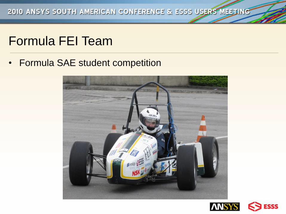
Formula FEI Team
• Formula SAE student competition
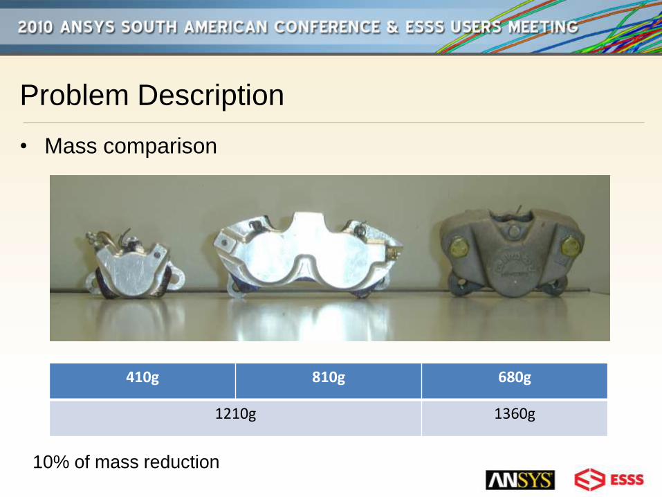
Problem Description
• Mass comparison
410g 810g 680g
1210g 1360g
10% of mass reduction
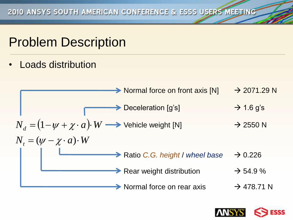
Problem Description
• Loads distribution
WaN
WaN
t
d
)(
1
Normal force on front axis [N]
Deceleration [g’s]
Vehicle weight [N]
Ratio C.G. height / wheel base
Rear weight distribution
Normal force on rear axis
2071.29 N
1.6 g’s
2550 N
0.226
54.9 %
478.71 N
Problem Description
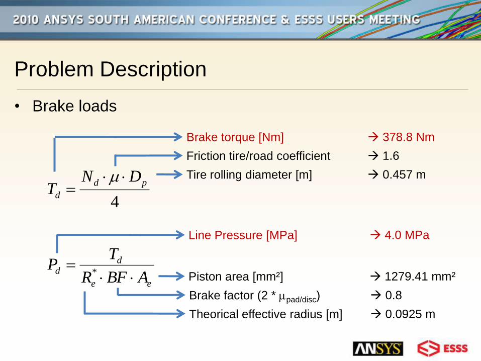
• Brake loads
4
pd
d
DNT
Brake torque [Nm]
Friction tire/road coefficient
Tire rolling diameter [m]
378.8 Nm
1.6
0.457 m
ee
dd
ABFR
TP
*
Line Pressure [MPa]
Piston area [mm²]
4.0 MPa
1279.41 mm²
Brake factor (2 * pad/disc) 0.8
Theorical effective radius [m] 0.0925 m

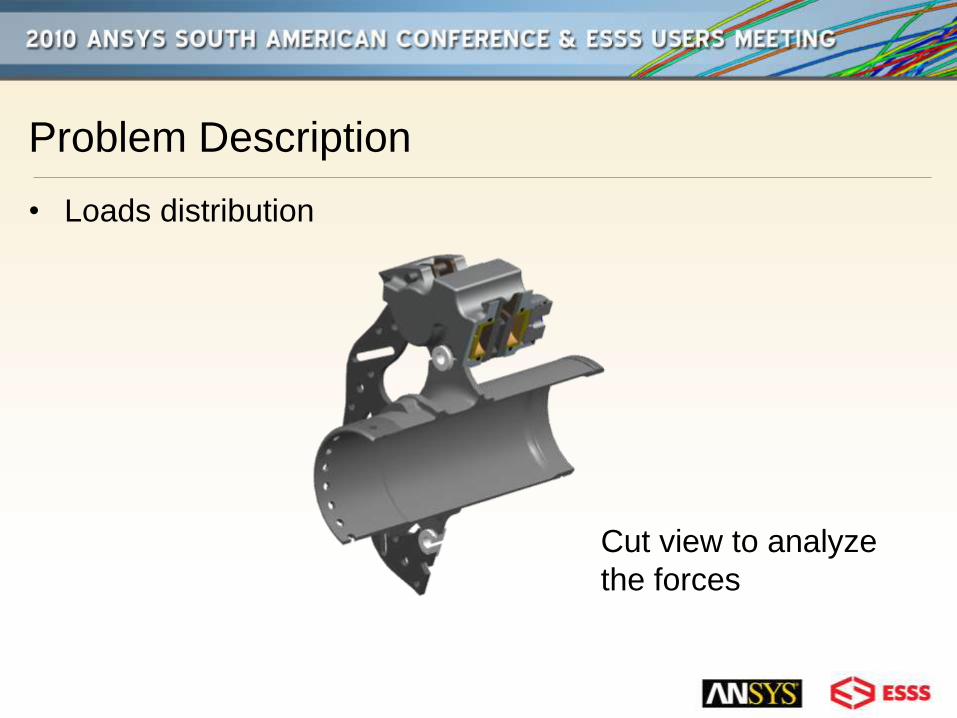
Problem Description
• Loads distribution
Problem Description
• Loads distribution
Cut view to analyze
the forces

Problem Description
• Loads distribution Pressure = 4 MPa
Normal disc force
reaction
Causing by
pressure
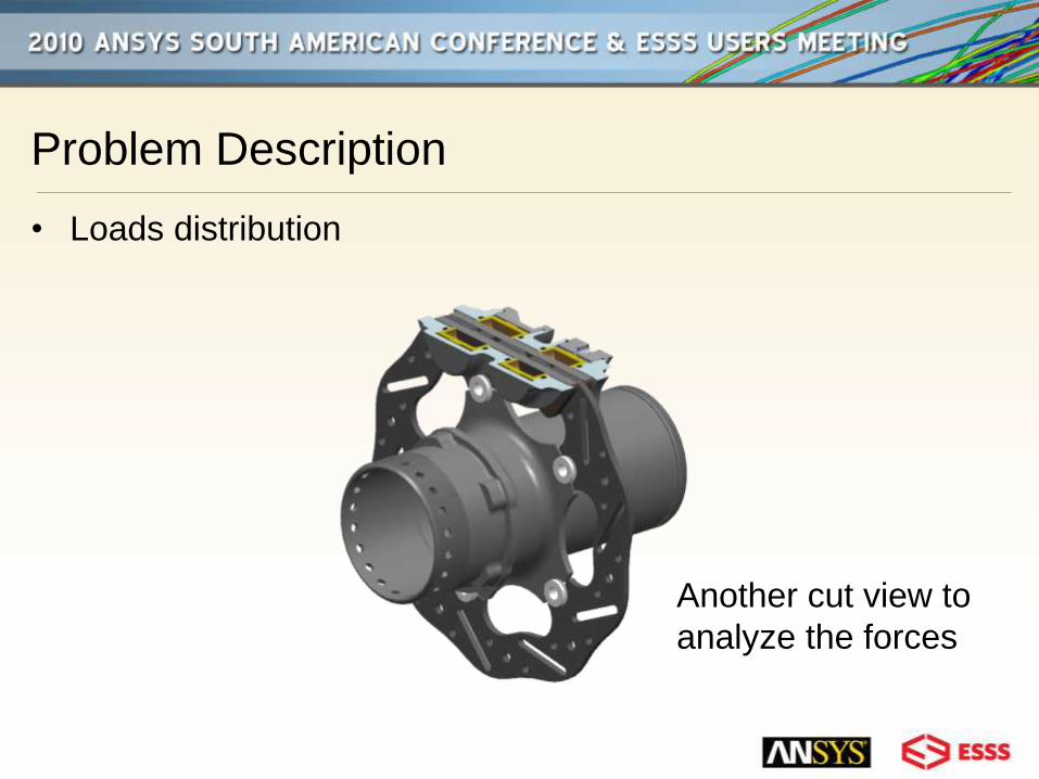
Problem Description
• Loads distribution
Another cut view to
analyze the forces
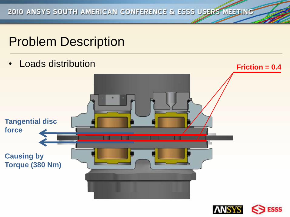
Problem Description
• Loads distribution Friction = 0.4
Tangential disc
force
Causing by
Torque (380 Nm)
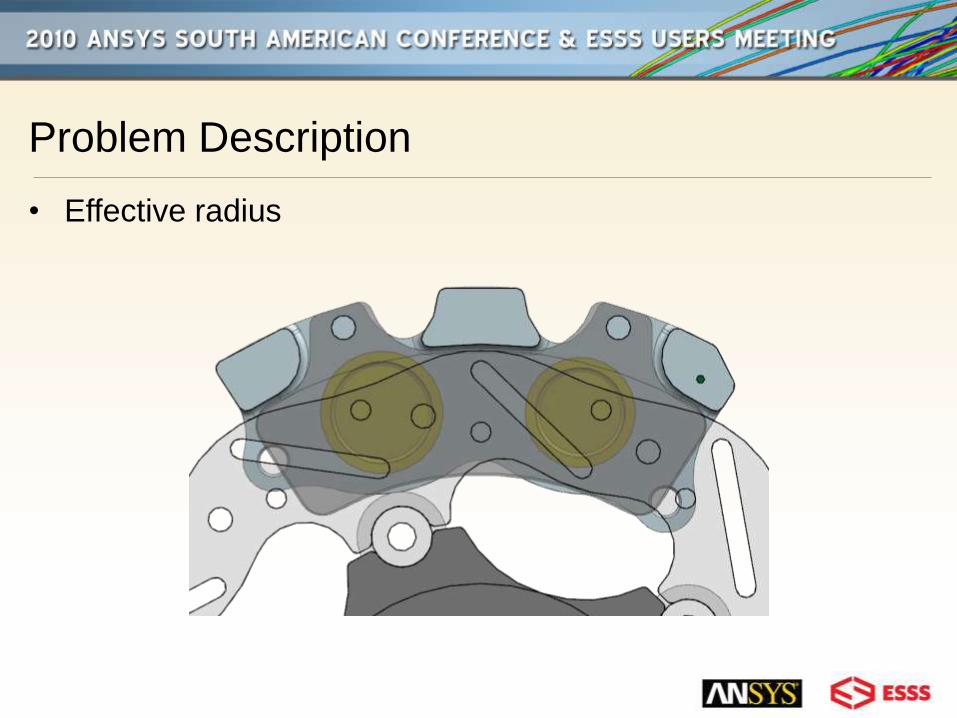
Problem Description
• Effective radius

Problem Description
• Effective radius
Re
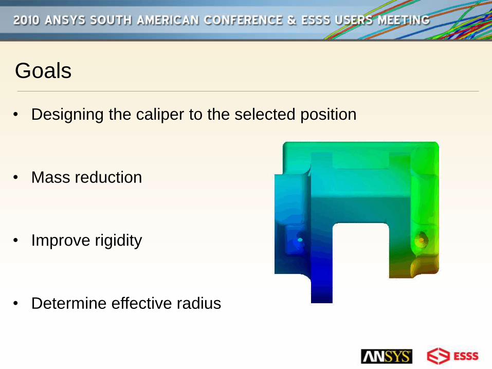
Goals
• Designing the caliper to the selected position
• Mass reduction
• Improve rigidity
• Determine effective radius
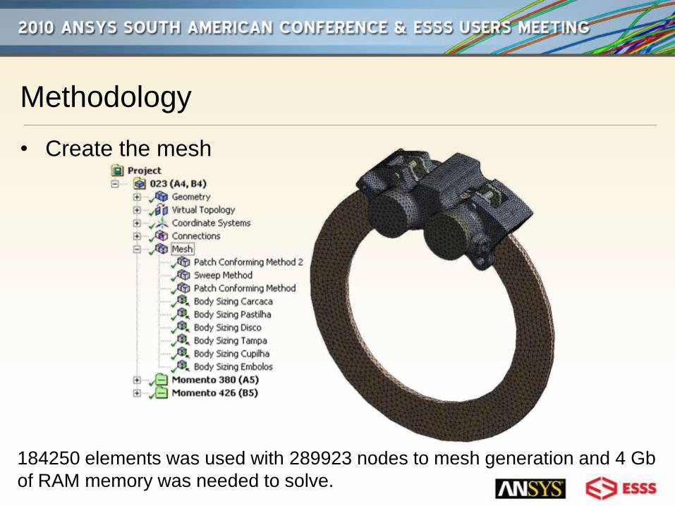
Methodology
• Create the mesh
184250 elements was used with 289923 nodes to mesh generation and 4 Gb
of RAM memory was needed to solve.
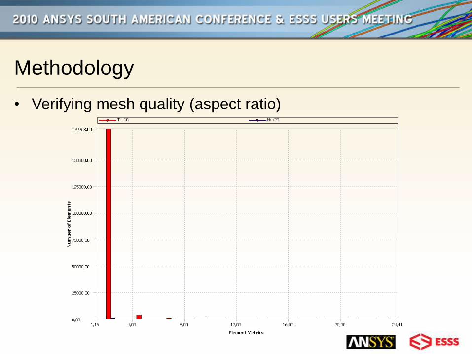
Methodology
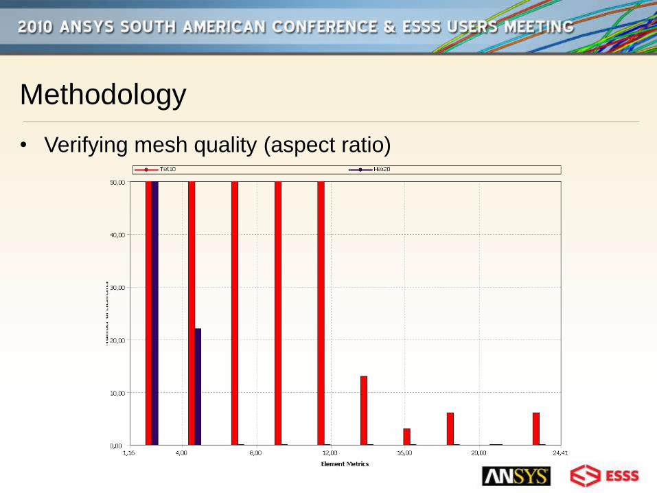
• Verifying mesh quality (aspect ratio)
Methodology
• Verifying mesh quality (aspect ratio)
Methodology
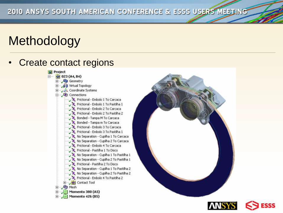
• Create contact regions
Methodology
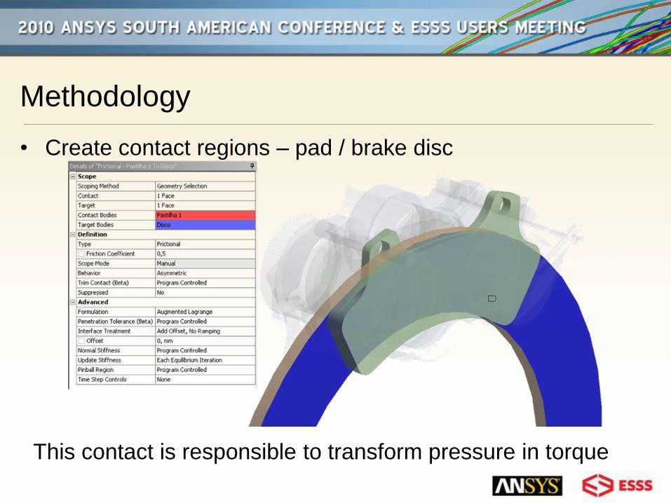
• Create contact regions – pad / brake disc
This contact is responsible to transform pressure in torque
Methodology
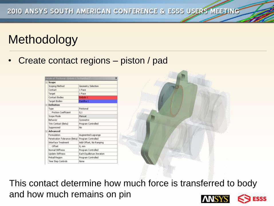
• Create contact regions – piston / pad
This contact determine how much force is transferred to body
and how much remains on pin
Methodology
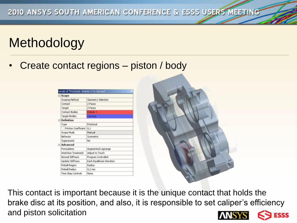
• Create contact regions – piston / body
This contact is important because it is the unique contact that holds the
brake disc at its position, and also, it is responsible to set caliper’s efficiency
and piston solicitation
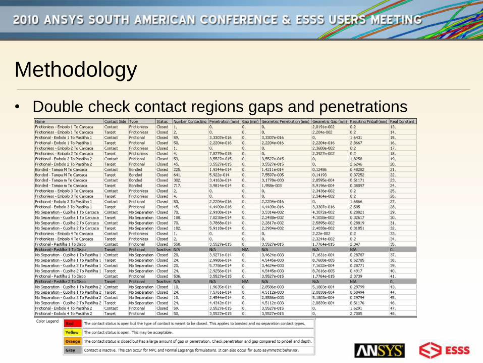
Methodology
• Double check contact regions gaps and penetrations
Methodology
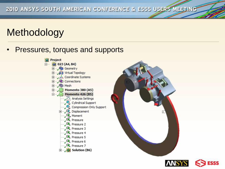
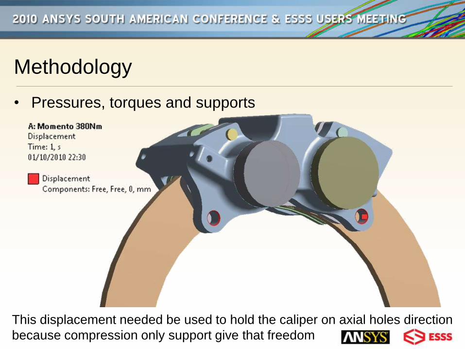
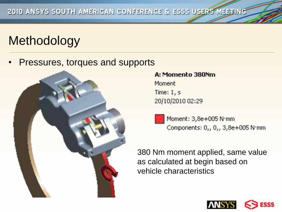
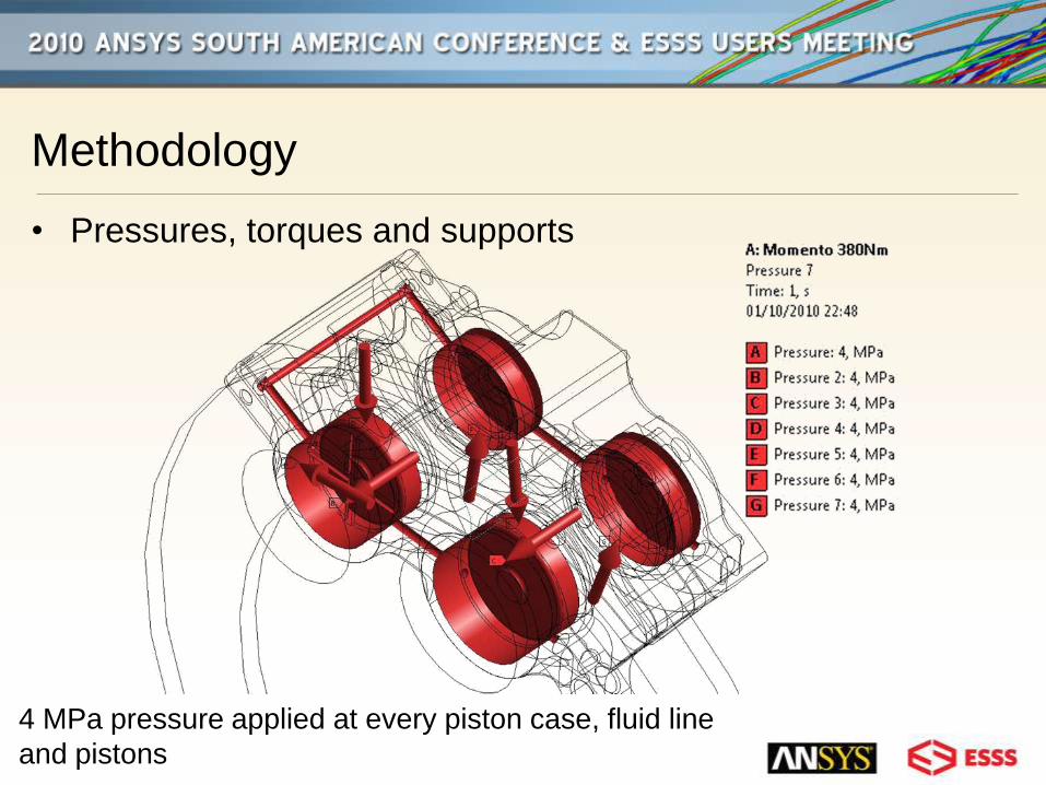
• Pressures, torques and supports
Methodology
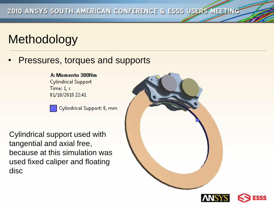
• Pressures, torques and supports
Cylindrical support used with
tangential and axial free,
because at this simulation was
used fixed caliper and floating
disc

Methodology
• Pressures, torques and supports
Compression only support was selected to give a real condition at holes,
although it requires more process time
Methodology
• Pressures, torques and supports
This displacement needed be used to hold the caliper on axial holes direction
because compression only support give that freedom
Methodology
• Pressures, torques and supports
380 Nm moment applied, same value
as calculated at begin based on
vehicle characteristics
Methodology
• Pressures, torques and supports
4 MPa pressure applied at every piston case, fluid line
and pistons
Methodology
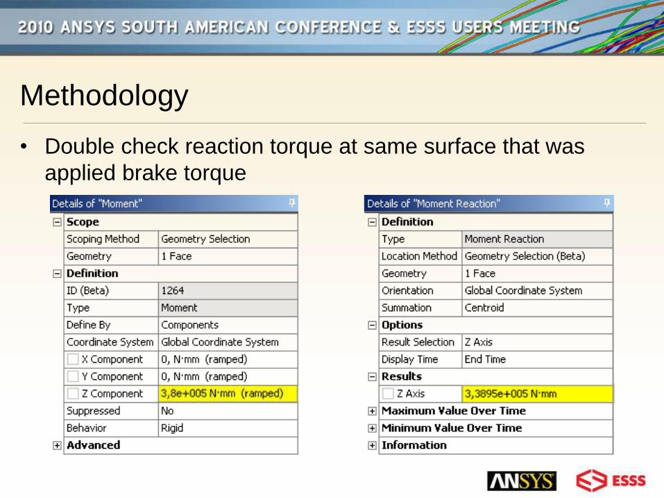
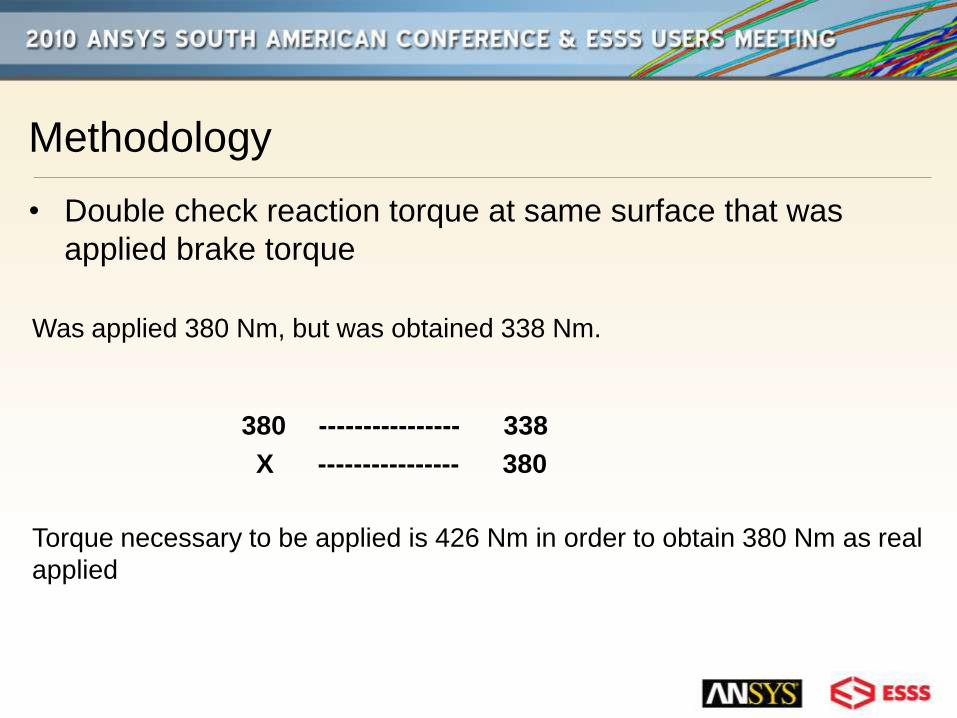
• Double check reaction torque at same surface that was
applied brake torque
Methodology
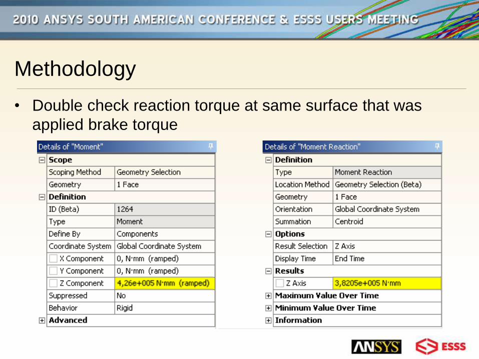
• Double check reaction torque at same surface that was
applied brake torque
Was applied 380 Nm, but was obtained 338 Nm.
380 ---------------- 338
X ---------------- 380
Torque necessary to be applied is 426 Nm in order to obtain 380 Nm as real
applied
Methodology
• Double check reaction torque at same surface that was
applied brake torque
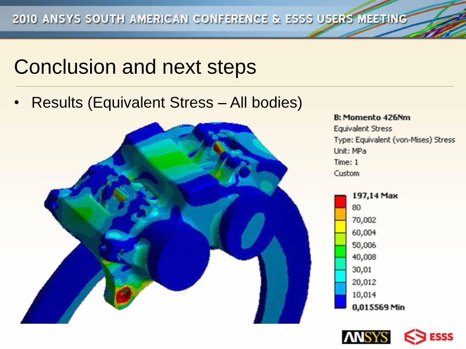
Conclusion and next steps
• Results (Equivalent Stress – All bodies)
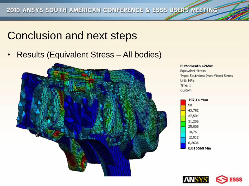
Conclusion and next steps
• Results (Equivalent Stress – All bodies)
Conclusion and next steps
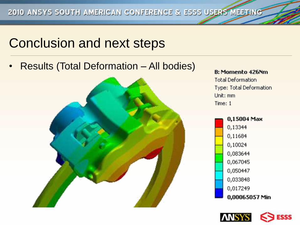
• Results (Total Deformation – All bodies)
Conclusion and next steps
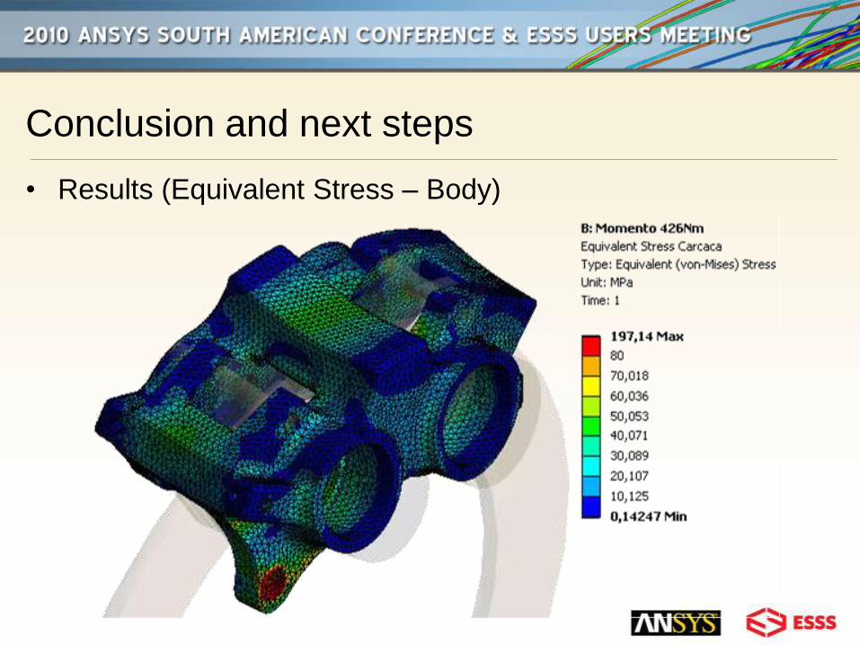
• Results (Equivalent Stress – Body)
Conclusion and next steps
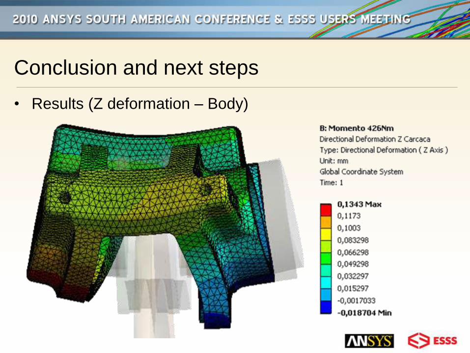
• Results (Z deformation – Body)
Conclusion and next steps
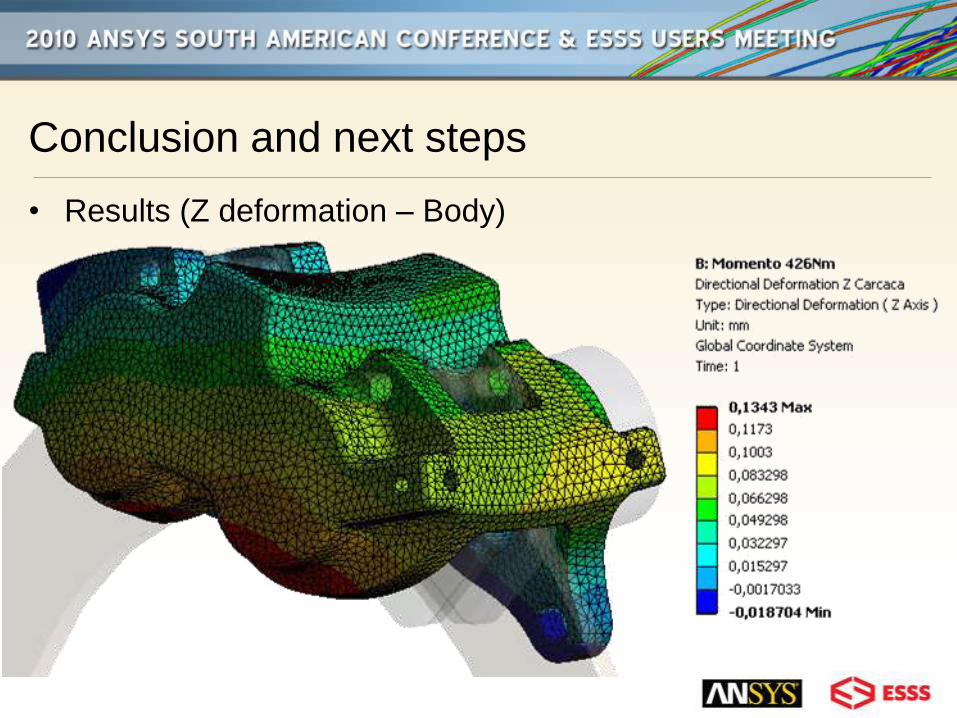
• Results (Z deformation – Body)
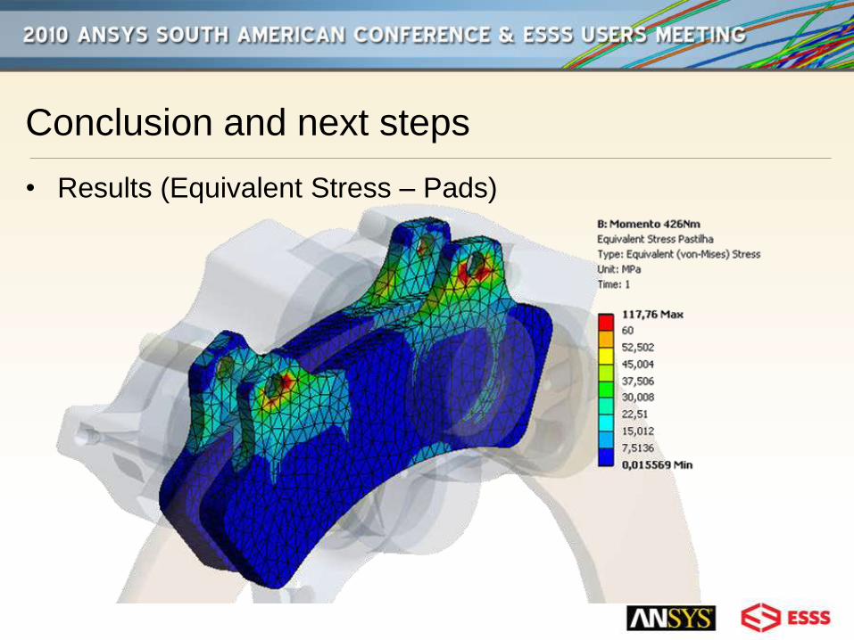
Conclusion and next steps
• Results (Equivalent Stress – Pads)
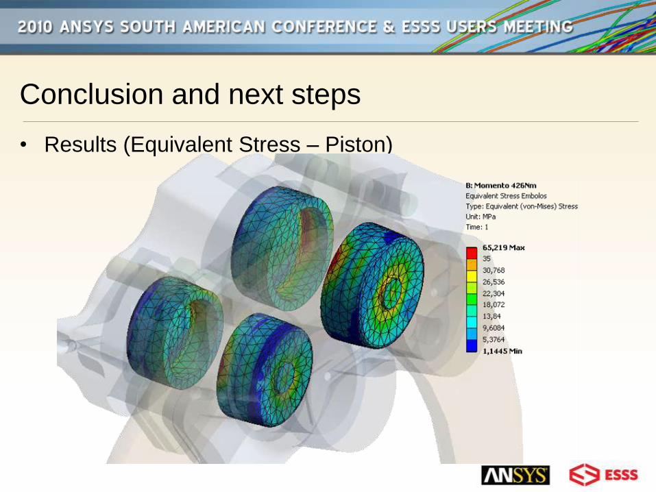
Conclusion and next steps
• Results (Equivalent Stress – Piston)
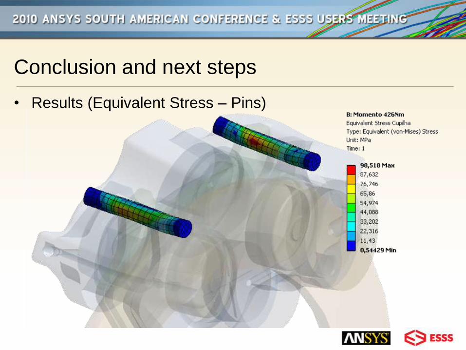
Conclusion and next steps
• Results (Equivalent Stress – Pins)
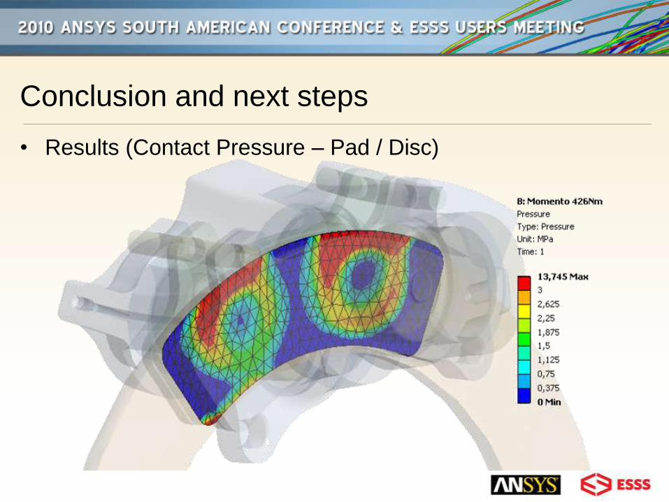
Conclusion and next steps
• Results (Contact Pressure – Pad / Disc)
Conclusion and next steps
• It’s possible to analyze a brake caliper with good precision
without to need a high level computer
• Start simulation with thermical DOF using friction heat
generation
THANKS
Prof. Dr. Roberto Bortolussi