Embed Size (px)
Citation preview
© AUG 2019 | IRE Journals | Volume 3 Issue 2 | ISSN: 2456-8880
IRE 1701439 ICONIC RESEARCH AND ENGINEERING JOURNALS 37
Design of Differential for Automobile Teaching Aid
SWE ZIN NYUNT1, ZARCHI THAUNG
2, AUNG HEIN LATT
3
1 Mechanical Engineering Department, Technological University (Thanlyin),Myanmar
2 Mechanical Engineering Department, Technological University (Maubin), Myanmar
3Mechanical Engineering Department, Government Technical Institute (Kyaiklatt), Myanmar
Abstract- Bevel gears areused to transmit the power
between two intersectingshafts at almost any angle or
speed.In automobiles and other wheeled vehicles, the
differential allows each of the driving road wheels to
rotate at different speeds, while for most vehicles
supplying equal torque to each of them. In this paper,
bevel gears in differential of Toyota Hilux 2L 2GD-
FTV engineare designed under structural condition
when the differential gear ratio is 3.583 at maximum
torque400Nm @ 2000 rpm.This 3D model
differential is designed by using solidworks software.
And then, differential for the teaching aid is
fabricated by usingAdditive Manufacturing
Technology.
Indexed Terms- Differential, Bevel Gear,
SOLIDWORKS, Additive Manufacturing, Teaching
Aid
I. INTRODUCTION
A differential is a device, usually, but not necessarily,
employing gears, which is connected to the outside
world by three shafts, through which it transmits
torque and rotation. Expect in some special-purpose
differentials, there are no other limitations on the
rotational speeds of the shafts. Any of the shafts can
be used to input rotation, and the other to output it.
Bevel gears transmit power between two intersecting
shafts at any angle or between non- intersecting
shafts.Pitch cone and back cone elements are
perpendicular to each other.In automobiles and other
wheeled vehicles, the differential allows each of the
driving roadwheels to rotate at different speeds, while
for most vehicles supplying equal torque to each of
them.[1]
In automobiles and other wheeled vehicles, a
differential allows the driving road wheels to rotate at
different speeds. This is necessary when the vehicle
turns, making the wheel that is travelling around the
outside of the turning curve roll farther and faster
than the other. The engine is connected to the shaft
rotating at angular velocity. The driving wheels are
connected to the other two shafts are equal. If the
engine is running at a constant speed, the rotational
speed of each driving wheel can vary, but the sum or
average of the two wheels’ speeds cannot change. An
increase in the speed of one wheel must be balanced
by an equal decrease in the speed of the other.A
different automotive application of differentials is in
epicyclical gearing. In each differential, one shaft is
connected to the engine through a clutch or
functionally similar device, another to the driving
wheels and the third shaft can be braked so its
angular velocity is zero. Several differentials, with
different gear ratios, are permanently connected in
parallel with each other, but only one of them has one
shaft broken so it cannot rotate, so it cannot rotate, so
only differential transmits power from the engine to
the wheels.[2]
Types of differential are open differential, limited-
slip differential, locking differential and automatic
locking differential.[3] In this paper, open differential
used in Toyota Hilux 2L 2GD- FTV engineis
designed and fabricated as teaching aids. This
teaching aid model is made of ABS (Acrylonitrile
Butadiene Styrene).
Fig. 1. Differentialof Automobile for Teaching Aid

© AUG 2019 | IRE Journals | Volume 3 Issue 2 | ISSN: 2456-8880
IRE 1701439 ICONIC RESEARCH AND ENGINEERING JOURNALS 38
In this paper, 3D modeldifferentialfor teaching aidis
designed by using solidworks software and produced
by using additive manufacturing technology. The
pedagogical model of differential is shown in figure
(1).
II. DESIGN OF BEVEL GEARS OF
DIFFERENTIAL
In the automobiles, bevel gears are used as the
differential crown wheel gear, pinion and side gears.
Bevel gears are analogous to a friction cone drive
when the conical surface of one drives that of the
other cone by friction. Since friction cone drive is not
attainable in practice, teeth are provided into these
cones for positive drive. The components of
differential of automobile are shown in figure (2).
Fig. 2.Components of Differential
The proportions of the bevel gears for crown wheel
gear and pinion may be taken as follows:
Addendum, a = 1 × m (1)
Dedendum, d = 1.2 × m (2)
Clearance = 0.2 × m (3)
Working depth = 2 × m (4)
Thickness of tooth = 1.5708 × m (5)
Where m is the standard module.
Outside or Addendum cone diameter
Do = Dp+ 2a cosθP (6)
Inside or Dedendum cone diameter
Dd = Dp– 2d cosθP (7)
Where Dp = Pitch diameter of the pinion (m).
Pitch angle for the pinion
θP1= tan-1
(TP / TG) (8)
Pitch angle for the gear
θP2= 90 –θP1 (9)
A sectional view of two bevel gears in mesh is shown
in figure (3). The terms used inconnection with bevel
gears are important from the subject point of view.
Various forces acting on the bevel gears, strength of
bevel gear, pitch diameter of the gear, pinion, the
dynamic load, tangential load and wear load for bevel
gearshave been calculated as follows:
Fig. 3.Terms used in Bevel Gears
A. Strength of Bevel Gears
The strength of a bevel gear tooth can be calculated
by using the Lewis equation for the tangential tooth
load is given as follows:
WT= (σo× Cv) b πmy' (L-b)/L (10) where σo= Allowable static stress and
Cv = Velocity factor
=3/ (3+ v), for teeth cut by form cutters,
= 6/ (6+ v), for teeth generated with
precision machines,
v = Peripheral speed in m / s,
b= Face width,
m= Module,
y' = Tooth form factor (or Lewis factor) for the
equivalent number ofteeth,
L = Slant height of pitch cone (or cone distance)
= DG
2
2
+ DP
2
2
(11)
DG= Pitch diameter of the gear, and
DP= Pitch diameter of the pinion.
© AUG 2019 | IRE Journals | Volume 3 Issue 2 | ISSN: 2456-8880
IRE 1701439 ICONIC RESEARCH AND ENGINEERING JOURNALS 39
The dynamic load for bevel gears WDis determined
by using the following Buckingham equation,
WD =WT + 21 𝑣 (bC + WT )
21 𝑣+ (bC + WT ) (12)
where WD = Total dynamic load (N),
WT = Steady transmitted load (N),
v = Pitch line velocity (m/s),
b = Face width of gears (mm) and
C = A deformation or dynamic factor (N/m).
The static tooth load or endurance strength of the
tooth for bevel gearsWs is given by
Ws = σeb πmy' (L-b)/L(13)
Where σe = Flexural endurance limit (MPa).
The maximum or limiting load for wear for bevel
gears Wwis given by
Ww = Dp b Q K / cos θP1 (14)
Where Ww = Maximum or limiting load for wear (N),
Dp = Pitch circle diameter of the pinion (mm),
Q = Ratio factor,
K = Load stress factor (N/mm2).
The load stress factor depends upon the maximum
fatigue limit of compressive stress, the pressure angle
and the modulus of elasticity of the materials of the
gears. According to Buckingham,load stress factorK
= {(σes )2
sin υ / 1.4 }{(1/EP)+ (1/EG)} (15)
Where σes = Surface endurance limit (MPa),
υ = Pressure angle,
EP = Young’s modulus for material of pinion (MPa),
EG = Young’s modulus for material of gear (MPa).
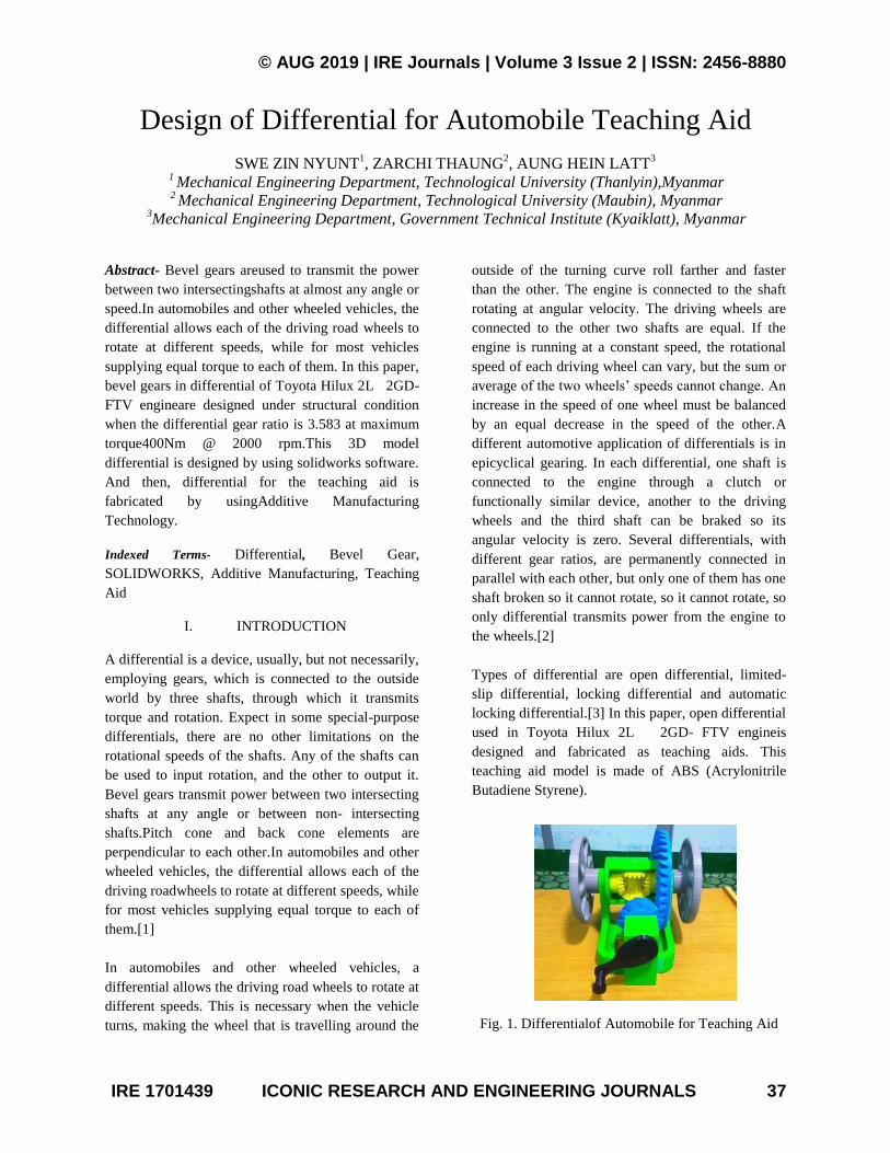
B. Forces Acting on a Bevel Gear
Consider a bevel gear and pinion in mesh. The
normal force (WN) on thetooth is perpendicular to the
tooth profile and thus makes an angle equal to the
pressure angle (υ) tothe pitch circle. Thus normal
force can be resolved into two components, one is the
tangential component(WT) and the other is the radial
component (WR). The tangential component produces
the bearing reactions while the radial component
produces end thrust in the shafts.[4] Forces acting on
the bevel gears are shown in figure (4).
Fig. 4.Forces acting on a Bevel Gear
The magnitude of the tangentialWT and radial
WRcomponents is as follows:
WT= WNcosυ, and WR= WNsinυ= WTtan υ (16)
Now the radial force (WR) acting at the mean radius
may be further resolved into twocomponents,
WRHand WRV, in the axial and radial directions.
Therefore theaxial force acting on the pinion shaft,
WRH= WRsin θP1= WTtan υsin θP1 (17)
the radial force acting on the pinion shaft,
WRV= WRcos θP1= WTtan υcos θP1 (18)
C. Design of a Shaft for Bevel Gears
For design a pinion shaft, WT= T/Rm(19)
Where T is the torque acting on the pinion and Rm is
the mean radius of pinion. The bending moment due
to WRH and WRV is given by
M1= WRV× overhang distance – WRH× Rm (20)
And the bending moment due to WT,
M2= WT × overhang distance (21)
The resultant bending moment,
M= M1 2 + M2
2 (22)
Since the shaft is subjected to twisting moment (T)
and resultant bending moment (M), therefore
equivalent twisting moment,
Te= M2 + T2 (23)
The diameter of pinion shaft may be obtained by
using the torsion equation.
Te = (π/16) × τ × (dp) 3
(24)
Where τ = shear stress for the material of the pinion
shaft and dp = diameter of pinion shaft.[4]

© AUG 2019 | IRE Journals | Volume 3 Issue 2 | ISSN: 2456-8880
IRE 1701439 ICONIC RESEARCH AND ENGINEERING JOURNALS 40
D. Design Calculation of Bevel Gears for Toyota
Hilux 2L 2GD-FTVEngine
Maximum Torque 400 Nm
Differential Gear Ratio 3.583
Maximum Torque (T) 400Nm @ 2000 rpm
Material Selection of
Gears AISI Alloy 4118
Ultimate Strength 517MPa
Yield Strength (σoP,G) 365Mpa
Young’s Modulus
(EP,G) 190 Gpa
Shear Strength (τ ) 320 Mpa
Characteristics or Proportions of Bevel Gears
Teeth of Pinion (TP) 12
Teeth of Gear (TG) 43
Pressure Angle (υ) 20°
Pitch Angle for Pinion
( θP1 ) 15.59°
Pitch Angle for Gear
( θP2 ) 74.4°
Standard Module (m) 8 mm
Face Width (b) 60 mm
Addendum (a) 8 mm
Dedendum (d) 10 mm
Clearance 1.6 mm
Working Depth 16 mm
Thickness of Tooth 12.6 mm
Outside or Addendum
cone diameter (Dop) 112 mm
Inside or Dedendum
cone diameter (Dd) 77.5 mm
Slant Height (L) 180 mm
Diameter of Pinion (Dp) 96 mm
Diameter of Gear (DG) 344 mm
Strength of Bevel Gears
Total Dynamic Load
(WD ) 20.7 kN
Flexural Endurance
Limit (σe) 700 MPa
Endurance Strength
(WS ) 56.7 kN
Surface Endurance
Llimit (σes) 1050 MPa
Maximum Load for
Wear (WW ) 31.5kN
Forces Acting on a Bevel Gear
Permissible Tangential
Tooth Load (WT) 10 kN
Axial Force Acting on
the Pinion Shaft (WRH ) 978 N
Radiall Force Acting on
the Pinion Shaft (WRV ) 3506 N
Design of a Pinion Shaft for Bevel Gear
Resultant Bending
Moment (M) 1.577 × 10
6Nmm
Equivalent Twisting
Moment (Te) 1.63 × 10
6Nmm
Diameter of Pinion
Shaft (dp) 30 mm
III. 3D MODELING OF DIFFERENTIAL
Rapid prototyping in the classroom by students is
low-cost ability,but also the fabrication of low-cost
high-quality scientificequipment from open hardware
designs forming opensource labs. Future applications
for 3D printing mightinclude creating open-source
scientific equipment.[5] Additive Manufacturing
(AM) refers to a process by whichdigital 3D design
data is used to build up a component in layersby
depositing material.This manufacturing is a new and
innovative method used to manufacture solid
objects.These 3D shapes are initially created on a
computer using solid modeling software, which can
be downloaded into the printer. Depending on shape,
material, series volume and other criteria, series
production is economically possible using metal
additive manufacturing.[6]Additive manufacturing
system is a process by which digital 3D design data is
used to build up a component in layers by deposing
material. A range of different metals, plastic and
composite materials may be used in additive
manufacturing system.[7]
To use additive manufacturing system, firstly,
differential of Toyota Hilux 2L 2GD- FTV engineis
created by using solidworks software. And then, the
model of differential is fabricated by using Maker

© AUG 2019 | IRE Journals | Volume 3 Issue 2 | ISSN: 2456-8880
IRE 1701439 ICONIC RESEARCH AND ENGINEERING JOURNALS 41
Bot machine which is used additive manufacturing
system. This Maker Botmachine is shown in figure
(5).
Fig. 5.MakerBot Machine
These 3Dprinted gearsare made of ABS
(Acrylonitrile Butadiene Styrene).These 3D model
gears before printing are shown in figure (5). Finally,
these parts of differential areassembled as teaching
aid.The assemblyconsists of crown wheel gear,
pinion and side gears. This teaching aid for
differential was composed in a smaller but similar
scale size, including two wheels in order tosimulate
the behavior of the differential. This is shown in
figure (7).
Fig. 6.3D Printed Gears
Fig. 7.Differential Assembly
IV. CONCLUSION
Bevel gears in differential of Toyota Hilux 2L 2GD-
FTV engineare designed under structural condition
when the differential gear ratio is 3.583 at maximum
torque 400Nm @ 2000 rpm.Crown wheel gear and
pinion of differential are designed with steady
transmitted load, static tooth load or endurance
strength, limiting load for wear and dynamic load by
using AISI Alloy 4118 steel, Yield Strength320 Mpa
and Young’s Modulus190 Gpa.
Crown wheel gear and pinion of differential are
designed under structural condition and modeled by
using solidworks software. And then, differential for
the teaching aid is created by using Additive
Manufacturing Technology.Additive manufacturing
is opposed to subtractive processes. These 3Dprinted
gears are made of ABS (Acrylonitrile Butadiene
Styrene).This teaching aid for differential was
composed in a smaller but similar scale size,
including two wheels in order tosimulate the behavior
of the differential. This teaching aid is easy
todemonstrate about the function of automobile
differential in the classroom.
ACKNOWLEDGMENT
The author thanks to Colleagues from Department of
Additive Manufacturing and Reverse Engineering,
Automotive Technology Research Institute
(PyinOoLwin) andour parents, for their supports.
REFERENCES
[1] Hiller, V.A.W, 1979. “Motor Vehicle Basic
Principles, Hatchinsion & Co., Ltd. London”.

© AUG 2019 | IRE Journals | Volume 3 Issue 2 | ISSN: 2456-8880
IRE 1701439 ICONIC RESEARCH AND ENGINEERING JOURNALS 42
[2] Willaim H. Crouse, 1981, “Automotive
Mechanics, 8th
Edition”, Tata McGraw Hill
Publishing Company, Ltd.
[3] Martin W. Stocket, 1969. “Auto Mechanics
Fundamentals”
[4] R.S Khurmi, J.K. Gupta, “Machine Design”,
Eurasia Publishing House (PVT.) Ltd., New
Delhi, 2005.
[5] Additive Manufacturing: A supply chain wide
response to economic uncertainty and
environmental
[6] Sustainability" (PDF). on 15 January 2014.
[7] Design for Additive Manufacturing –
Supporting the Substitution of Components in
Series Products. Procedia CIRP 2014;21:138–
43.
[8] Baldinger M, Duchi A. High Value
Manufacturing. In: da Silva Bartolo PJ,
editors. High Value Manufacturing: Advanced
Research in Virtual and Rapid Prototyping:
Proceedings of the 6th International
Conference on Advanced Research in Virtual
and Rapid Prototyping.
[9] Hall, Hollow enho, Laughlin, 1961. Theory
and Problem of Machine Design, SOS series
Schoum Publising Co; New York.
[10] Nannan G and Ming C L 2013 Additive
manufacturing: technology, applications and
research needs Front. Mech. Eng. 8(3):
(Higher Education Press and Springer-Verlag
Berlin Heidelberg)
[11] Wohlers T, editor. Wohlers Report 2013 -
Additive Manufacturing and 3D Printing State
of the Industry - Annual Worldwide Progress
Report. 18th ed. Fort Collins, CO: Wohlers
Associates; 2013.
[12] Wright Doughlas, 2001. “Design and Analysis
of Machine Elements”. May 2005.
[13] Yang, S., and Zhao, Y., 2015, "Additive
manufacturing-enabled design theory and
methodology: a critical review," The
International Journal of Advanced
Manufacturing Technology.
[14] www.additivemanufacturing.com/basics/
[15] http://en.wikipedia.org/w/index.php
[16] www.MakeltFrom.com