Embed Size (px)
Citation preview
Available online at http://docs.lib.purdue.edu/jate
Journal of Aviation Technology and Engineering 7:1 (2017) 19–44
Design of DC-Link VSCF AC Electrical Power System for the Embraer190/195 Aircraft
Eduardo Francis Carvalho Freitas
ETEP – Faculdade de Tecnologia de Sao Jose dos Campos, Brazil
Nihad E. Daidzic
AAR Aerospace Consulting, LLC
Abstract
A proposed novel DC-Link VSCF AC-DC-AC electrical power system converter for Embraer 190/195 transport category airplane ispresented. The proposed converter could replace the existing conventional system based on the CSCF IDGs. Several contemporaryproduction airplanes already have VSCF as a major or backup source of electrical power. Problems existed with the older VSCF systemsin the past; however, the switched power electronics and digital controllers have matured and can be now, in our opinion, safely integratedand replace existing constant-speed hydraulic transmissions powering CSCF AC generators. IGBT power transistors for medium-levelpower conversion and relatively fast efficient switching are used. Electric power generation, conversion, distribution, protection, and loadmanagement utilizing VSCF offers flexibility, redundancy, and reliability not available with a conventional CSCF IDG systems. Theproposed DC-Link VSCF system for E190/195 delivers several levels of 3-w AC and DC power, namely 330/270/28 VDC and 200/115/26 VAC utilizing 12-pulse rectifiers, Buck converters, and 3-w 12-step inverters with D-Y, Y-Y, and Y-D 3-wtransformers. Conventional bipolar double-edge carrier-based pulse-width-modulation using three reference AC phasesignals and up to 100 kHz triangular carriers are used in a manner to remove all even and many odd super-harmonics.Passive low-pass filters are used to remove higher harmonics. The RL AC loads are active in connection with thesynchronous and induction AC motors and also include passive AC loads. The overall power factor exceeded 85%. Totalharmonic distortions for voltages and currents are below 5%, thus satisfying the MIL-STD-704F and the IEEE Std. 519power-quality standards, while avoiding the need for active filters. Several PI and PID controllers that regulate synchronousgenerator DC excitation and inverter banks were designed and tuned using the continuous–cycle tuning method to offerrequired performance and stability of the feedback loop. Mathworks’s SimulinkTM software was used for simulation ofelectrical components and circuits. Several critical scenarios of aircraft operations were simulated, such as go-around, toevaluate the transient behavior of the VSCF system.
Keywords: transport-category aircraft electrical power systems, electrical DC-link VSCF power systems, pulse-width-modulation, power inverters, powerelectronics, insulated gate bipolar transistors, tuning of PI controllers, total harmonic distortion, passive filters
All correspondence concerning this article should be directed to Nihad Daidzic at [email protected].
http://dx.doi.org/10.7771/2159-6670.1155
Introduction
The electrical system is one of the major non-propulsivepower systems in transport category (T-category) FAR/CS25 aircraft. The main purpose of the electrical system isto provide power for a plethora of electrically driven pumps(hydraulic fluid, fuel, lubricants, coolants, etc.), compres-sors (pneumatic air), fans (cooling, environmental cabincontrol, etc.), heating, and anti-icing equipment. Addition-ally, low-voltage power (28 VDC or 26 VAC) is provi-ded for numerous redundant computer systems (flightand engine control, etc.) and various avionics (AviationElectronics) systems (Moir, Seabridge, & Jukes, 2013).This includes navigation and communication equipment.Last but not least, electric power is needed for lightingsystems (14 CFR 25.1381 through 25.1387) and properfunctioning of much of the miscellaneous equipment(14 CFR 25.1431 through 25.1461; electrical wiringinterconnection systems are covered in 14 CFR 25.1701through 25.1733). The other two major non-propulsiveaircraft power systems are hydraulic and pneumatic (Moir& Seabridge, 2008; Wild, 2008).
Design and certification of T-category electrical systemsis governed by 14 CFR 25.1351 through 25.1365 (FAA,2014). Similarly, EASA’s CS 25 Subpart F (Equipment),25.1351 through 25.1365, regulations must be followed whendesigning and certifying electrical systems for T-categoryairplanes under its jurisdiction (EASA, 2007). The Air Trans-portation Association of America (ATA) specification 100identifier 24 (electrical power) is used to classify aircraft ele-ctrical systems (Davies, 2003). Typically, IEEE 519 (IEEE,
1992) and MIL-STD-704F (US DOD, 2008) are utilized asguidance when designing aircraft electrical and electroniccomponents.
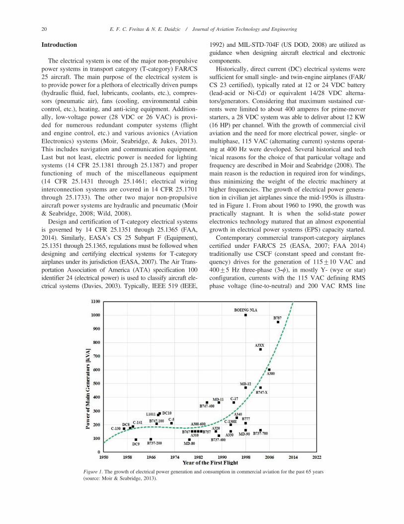
Historically, direct current (DC) electrical systems weresufficient for small single- and twin-engine airplanes (FAR/CS 23 certified), typically rated at 12 or 24 VDC battery(lead-acid or Ni-Cd) or equivalent 14/28 VDC alterna-tors/generators. Considering that maximum sustained cur-rents were limited to about 400 amperes for prime-moverstarters, a 28 VDC system was able to deliver about 12 KW(16 HP) per channel. With the growth of commercial civilaviation and the need for more electrical power, single- ormultiphase, 115 VAC (alternating current) systems operat-ing at 400 Hz were developed. Several historical and tech‘nical reasons for the choice of that particular voltage andfrequency are described in Moir and Seabridge (2008). Themain reason is the reduction in required iron for windings,thus minimizing the weight of the electric machinery athigher frequencies. The growth of electrical power genera-tion in civilian jet airplanes since the mid-1950s is illustra-ted in Figure 1. From about 1960 to 1990, the growth waspractically stagnant. It is when the solid-state powerelectronics technology matured that an almost exponentialgrowth in electrical power systems (EPS) capacity started.
Contemporary commercial transport-category airplanescertified under FAR/CS 25 (EASA, 2007; FAA 2014)traditionally use CSCF (constant speed and constant fre-quency) drives for the generation of 115¡10 VAC and400¡5 Hz three-phase (3-w), in mostly Y- (wye or star)configuration, currents with the 115 VAC defining RMSphase voltage (line-to-neutral) and 200 VAC RMS line
Figure 1. The growth of electrical power generation and consumption in commercial aviation for the past 65 years(source: Moir & Seabridge, 2013).
20 E. F. C. Freitas & N. E. Daidzic / Journal of Aviation Technology and Engineering
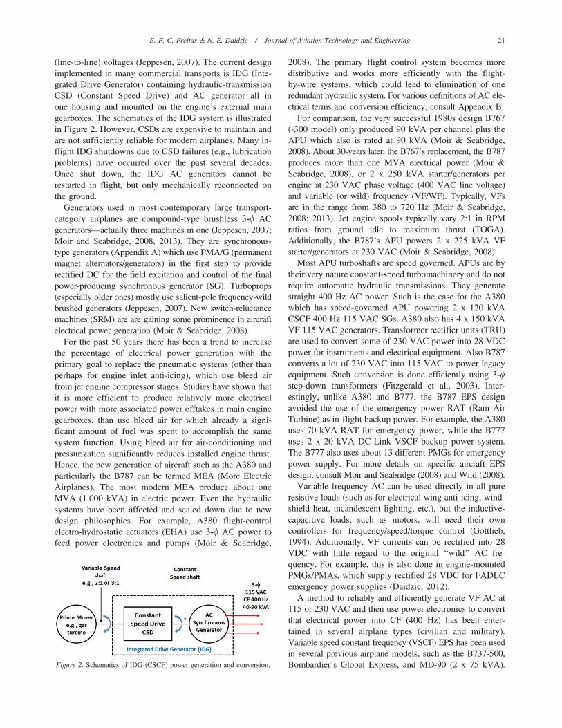
(line-to-line) voltages (Jeppesen, 2007). The current designimplemented in many commercial transports is IDG (Inte-grated Drive Generator) containing hydraulic-transmissionCSD (Constant Speed Drive) and AC generator all inone housing and mounted on the engine’s external maingearboxes. The schematics of the IDG system is illustratedin Figure 2. However, CSDs are expensive to maintain andare not sufficiently reliable for modern airplanes. Many in-flight IDG shutdowns due to CSD failures (e.g., lubricationproblems) have occurred over the past several decades.Once shut down, the IDG AC generators cannot berestarted in flight, but only mechanically reconnected onthe ground.
Generators used in most contemporary large transport-category airplanes are compound-type brushless 3-w ACgenerators—actually three machines in one (Jeppesen, 2007;Moir and Seabridge, 2008, 2013). They are synchronous-type generators (Appendix A) which use PMA/G (permanentmagnet alternators/generators) in the first step to providerectified DC for the field excitation and control of the finalpower-producing synchronous generator (SG). Turboprops(especially older ones) mostly use salient-pole frequency-wildbrushed generators (Jeppesen, 2007). New switch-reluctancemachines (SRM) are are gaining some prominence in aircraftelectrical power generation (Moir & Seabridge, 2008).
For the past 50 years there has been a trend to increasethe percentage of electrical power generation with theprimary goal to replace the pneumatic systems (other thanperhaps for engine inlet anti-icing), which use bleed airfrom jet engine compressor stages. Studies have shown thatit is more efficient to produce relatively more electricalpower with more associated power offtakes in main enginegearboxes, than use bleed air for which already a signi-ficant amount of fuel was spent to accomplish the samesystem function. Using bleed air for air-conditioning andpressurization significantly reduces installed engine thrust.Hence, the new generation of aircraft such as the A380 andparticularly the B787 can be termed MEA (More ElectricAirplanes). The most modern MEA produce about oneMVA (1,000 kVA) in electric power. Even the hydraulicsystems have been affected and scaled down due to newdesign philosophies. For example, A380 flight-controlelectro-hydrostatic actuators (EHA) use 3-w AC power tofeed power electronics and pumps (Moir & Seabridge,
2008). The primary flight control system becomes moredistributive and works more efficiently with the flight-by-wire systems, which could lead to elimination of oneredundant hydraulic system. For various definitions of AC ele-ctrical terms and conversion efficiency, consult Appendix B.
For comparison, the very successful 1980s design B767(-300 model) only produced 90 kVA per channel plus theAPU which also is rated at 90 kVA (Moir & Seabridge,2008). About 30-years later, the B767’s replacement, the B787produces more than one MVA electrical power (Moir &Seabridge, 2008), or 2 x 250 kVA starter/generators perengine at 230 VAC phase voltage (400 VAC line voltage)and variable (or wild) frequency (VF/WF). Typically, VFsare in the range from 380 to 720 Hz (Moir & Seabridge,2008; 2013). Jet engine spools typically vary 2:1 in RPMratios from ground idle to maximum thrust (TOGA).Additionally, the B787’s APU powers 2 x 225 kVA VFstarter/generators at 230 VAC (Moir & Seabridge, 2008).
Most APU turboshafts are speed governed. APUs are bytheir very nature constant-speed turbomachinery and do notrequire automatic hydraulic transmissions. They generatestraight 400 Hz AC power. Such is the case for the A380which has speed-governed APU powering 2 x 120 kVACSCF 400 Hz 115 VAC SGs. A380 also has 4 x 150 kVAVF 115 VAC generators. Transformer rectifier units (TRU)are used to convert some of 230 VAC power into 28 VDCpower for instruments and electrical equipment. Also B787converts a lot of 230 VAC into 115 VAC to power legacyequipment. Such conversion is done efficiently using 3-wstep-down transformers (Fitzgerald et al., 2003). Inter-estingly, unlike A380 and B777, the B787 EPS designavoided the use of the emergency power RAT (Ram AirTurbine) as in-flight backup power. For example, the A380uses 70 kVA RAT for emergency power, while the B777uses 2 x 20 kVA DC-Link VSCF backup power system.The B777 also uses about 13 different PMGs for emergencypower supply. For more details on specific aircraft EPSdesign, consult Moir and Seabridge (2008) and Wild (2008).
Variable frequency AC can be used directly in all pureresistive loads (such as for electrical wing anti-icing, wind-shield heat, incandescent lighting, etc.), but the inductive-capacitive loads, such as motors, will need their owncontrollers for frequency/speed/torque control (Gottlieb,1994). Additionally, VF currents can be rectified into 28VDC with little regard to the original ‘‘wild’’ AC fre-quency. For example, this is also done in engine-mountedPMGs/PMAs, which supply rectified 28 VDC for FADECemergency power supplies (Daidzic, 2012).
A method to reliably and efficiently generate VF AC at115 or 230 VAC and then use power electronics to convertthat electrical power into CF (400 Hz) has been enter-tained in several airplane types (civilian and military).Variable speed constant frequency (VSCF) EPS has been usedin several previous airplane models, such as the B737-500,Bombardier’s Global Express, and MD-90 (2 x 75 kVA).Figure 2. Schematics of IDG (CSCF) power generation and conversion.
E. F. C. Freitas & N. E. Daidzic / Journal of Aviation Technology and Engineering 21
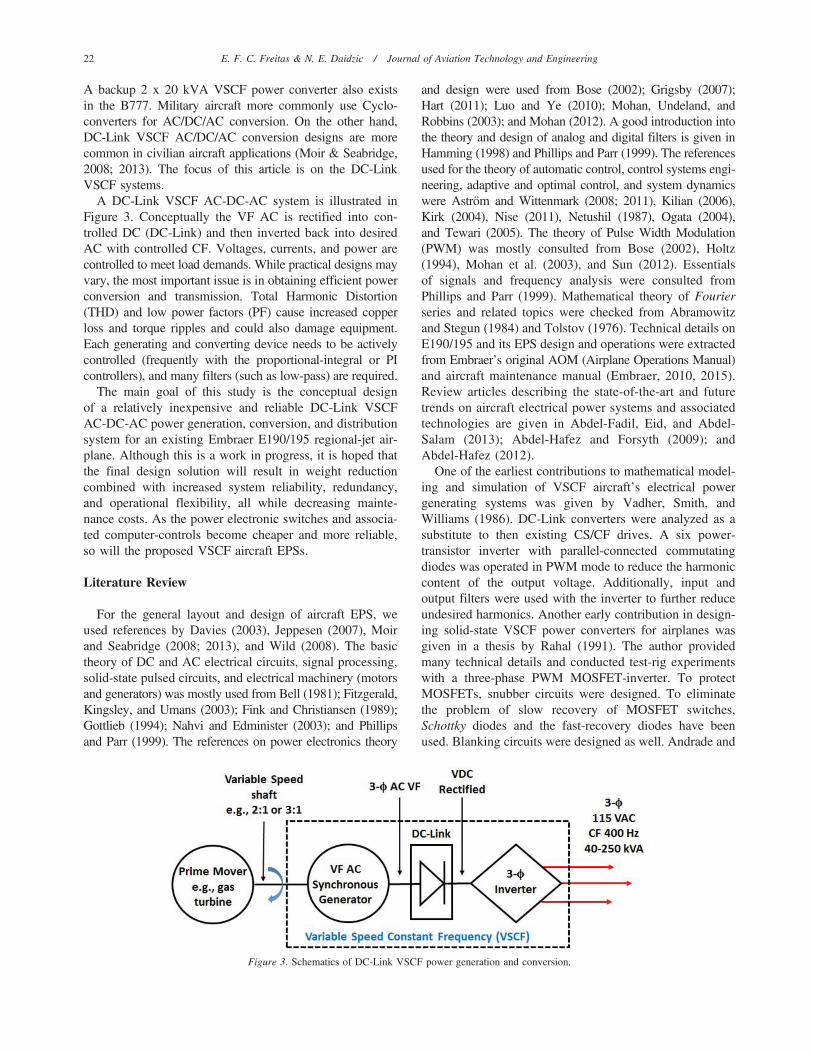
A backup 2 x 20 kVA VSCF power converter also existsin the B777. Military aircraft more commonly use Cyclo-converters for AC/DC/AC conversion. On the other hand,DC-Link VSCF AC/DC/AC conversion designs are morecommon in civilian aircraft applications (Moir & Seabridge,2008; 2013). The focus of this article is on the DC-LinkVSCF systems.
A DC-Link VSCF AC-DC-AC system is illustrated inFigure 3. Conceptually the VF AC is rectified into con-trolled DC (DC-Link) and then inverted back into desiredAC with controlled CF. Voltages, currents, and power arecontrolled to meet load demands. While practical designs mayvary, the most important issue is in obtaining efficient powerconversion and transmission. Total Harmonic Distortion(THD) and low power factors (PF) cause increased copperloss and torque ripples and could also damage equipment.Each generating and converting device needs to be activelycontrolled (frequently with the proportional-integral or PIcontrollers), and many filters (such as low-pass) are required.
The main goal of this study is the conceptual designof a relatively inexpensive and reliable DC-Link VSCFAC-DC-AC power generation, conversion, and distributionsystem for an existing Embraer E190/195 regional-jet air-plane. Although this is a work in progress, it is hoped thatthe final design solution will result in weight reductioncombined with increased system reliability, redundancy,and operational flexibility, all while decreasing mainte-nance costs. As the power electronic switches and associa-ted computer-controls become cheaper and more reliable,so will the proposed VSCF aircraft EPSs.
Literature Review
For the general layout and design of aircraft EPS, weused references by Davies (2003), Jeppesen (2007), Moirand Seabridge (2008; 2013), and Wild (2008). The basictheory of DC and AC electrical circuits, signal processing,solid-state pulsed circuits, and electrical machinery (motorsand generators) was mostly used from Bell (1981); Fitzgerald,Kingsley, and Umans (2003); Fink and Christiansen (1989);Gottlieb (1994); Nahvi and Edminister (2003); and Phillipsand Parr (1999). The references on power electronics theory
and design were used from Bose (2002); Grigsby (2007);Hart (2011); Luo and Ye (2010); Mohan, Undeland, andRobbins (2003); and Mohan (2012). A good introduction intothe theory and design of analog and digital filters is given inHamming (1998) and Phillips and Parr (1999). The referencesused for the theory of automatic control, control systems engi-neering, adaptive and optimal control, and system dynamicswere Astrom and Wittenmark (2008; 2011), Kilian (2006),Kirk (2004), Nise (2011), Netushil (1987), Ogata (2004),and Tewari (2005). The theory of Pulse Width Modulation(PWM) was mostly consulted from Bose (2002), Holtz(1994), Mohan et al. (2003), and Sun (2012). Essentialsof signals and frequency analysis were consulted fromPhillips and Parr (1999). Mathematical theory of Fourierseries and related topics were checked from Abramowitzand Stegun (1984) and Tolstov (1976). Technical details onE190/195 and its EPS design and operations were extractedfrom Embraer’s original AOM (Airplane Operations Manual)and aircraft maintenance manual (Embraer, 2010, 2015).Review articles describing the state-of-the-art and futuretrends on aircraft electrical power systems and associatedtechnologies are given in Abdel-Fadil, Eid, and Abdel-Salam (2013); Abdel-Hafez and Forsyth (2009); andAbdel-Hafez (2012).
One of the earliest contributions to mathematical model-ing and simulation of VSCF aircraft’s electrical powergenerating systems was given by Vadher, Smith, andWilliams (1986). DC-Link converters were analyzed as asubstitute to then existing CS/CF drives. A six power-transistor inverter with parallel-connected commutatingdiodes was operated in PWM mode to reduce the harmoniccontent of the output voltage. Additionally, input andoutput filters were used with the inverter to further reduceundesired harmonics. Another early contribution in design-ing solid-state VSCF power converters for airplanes wasgiven in a thesis by Rahal (1991). The author providedmany technical details and conducted test-rig experimentswith a three-phase PWM MOSFET-inverter. To protectMOSFETs, snubber circuits were designed. To eliminatethe problem of slow recovery of MOSFET switches,Schottky diodes and the fast-recovery diodes have beenused. Blanking circuits were designed as well. Andrade and
Figure 3. Schematics of DC-Link VSCF power generation and conversion.
22 E. F. C. Freitas & N. E. Daidzic / Journal of Aviation Technology and Engineering
Tenning (1992) reported on early designs of B777 EPS,which also included VSCF DC-Link EPS backup of20 kVA. Also a new redundant two-way communicationbus ARINC 629 was developed specifically for use in B777to communicate between various control units, monitor,and provide built-in-test information (Andrade & Tenning,1992; Moir, Seabridge, & Jukes, 2013). Shiao and Lin(1995) proposed a compact induction-type generator forVSCF aircraft electrical system IGVSCF). The authorsused the familiar dq0-axes generator model, RL loadsmodel, and (5 kVA three-phase 110 V) PWM invertermodel. The authors claimed that the compact induc-tion generator VSCF (IGVSCF) system presented couldincrease efficiency and reliability and further reducethe required maintenance manpower per flight hour. Theperformance of the IGVSCF system was simulated bythe computer program and the experimental operationperformed on a prototype IGVSCF system. The simulatedresults and experimental tests demonstrated higher effi-ciency of IGVSCF compared to more conventional designs.The thesis by Jadric (1998) is interesting as the VSCFsystem was designed utilizing the ground-based variable-speed gas-turbine for electrical power generation. A systemanalyzed consisted of a variable-speed SG that supplies anactive DC load to inverter through a 3-w diode rectifierrequired adequate modeling in both time and frequencydomain. The average model developed accounts fordynamics of generator and load, and for effects of thenon-ideal operation of diode rectifier. The model is non-linear, but time continuous, and can be used for large- andsmall-signal analysis.
Gong and colleagues (2005) performed comparativeevaluation of 3-w high power-factor AC-DC converter forfuture MEA applications. The authors used passive 12-pulserectifier, two- and three-level active PWM rectifiers toanalyze DC-Link used to supply 5 kW power to a variable-speed hydraulic pump. Eid and colleagues (2010a, 2010b)conducted an investigation of power quality of a VSCFDC-Link system for aircraft EPS. The authors demonstratedthe application of VSCF by 12-pulse converters and powerpassive filters in the power generation in the aircraft ele-ctrical system. The output power for the simulation anddesign was similar to a Boeing 767 with two channels of90 kVA. To obtain results, several load combinations wereused. Passive and dynamic AC loads and DC loads wereapplied to simulate the design. An EPS was designed with aSG that has an output of 360 to 800 Hz frequency range.A 12-pulse TRU was used in the output of the generator inorder to obtain DC voltage. The 12-pulse converter waschosen because it has inherent high PF and low THD. Theregulation of TRU was conducted utilizing PI control topower a 270 VDC DC-bus. Three different DC loads wereconnected to the DC bus by DC/DC converters. A 12-pulseinverter was used to provide 200 VAC at 400 Hz and a PIcontroller to regulate the right parameter in the AC bus. AC
loads composed of three passive loads with 18, 2.6, and15.5 kVA of electrical power and three dynamic loadscomposed by motors of different electrical power (11.2, 7.5,and 5.0 kW) were also connected to the AC bus.
El-Kishky, Ibrahimi, Abu Dakka, Eid, and Abdel-Akher(2011) present a comprehensive model of a VSCF aircraftelectric power system with a large share of nonlinear loads.The model was used to study the performance of the systemunder different nonlinear loading conditions. Both transientand steady-state performance characteristics of the systemwere investigated and compared to applicable aircraft EPSstandards (IEEE and military standards). Nya, Brombach,and Schulz (2012) discussed continuously increasingaircraft electrical power demands. New electric voltagelevels are actually alluded to in order to respond to demandchallenges. Many advantages of high voltage alternatingcurrent (HVAC) and high voltage direct current (HVDC) inan aircraft EPS (namely 230 VAC CF/VF and +/-270 VDC,or 540V DC, between the positive and the negative poten-tials) are presented and compared with the conventional115 VAC CF/VF and 28 VDC systems. Power quality,weight comparison, and applicability were exhibited at powergeneration, distribution, and load level. Issues regarding thesimultaneous supply with HVAC/HVDC and associated cur-rent technology research were discussed.
Khaburi and Nazempour (2012) used the dq0 model of a2-pole, 30 kW, line-to-line voltage 480 V, 96,000 RPM,PMSM (permanent magnet synchronous machine/genera-tor) powered by a microturbine and the PWM rectifier toconvert variable- and high-frequency AC generated by avariable-speed (VS) microturbine. Using a 2 kHz carrierbased PWM voltage source inverter (VSI) with six insula-ted gate bipolar transistors (IGBTs) and six anti-paralleldiodes, DC was converted to high-quality AC with lowTHD. Harmonics in inverter output, centered on multiplesof 2 kHz, were cleaned using an LC filter. The authorsreported excellent dynamic response and decoupled controlof active and reactive powers with the step change transientusing virtual flux based direct power control (VF-DPC).Trentin, Zanchetta, Wheeler, and Clare (2013) proposedAC-DC power conversion for a new generation of aircraftwhich distributes only DC power over 28 and 270 VDC(HVAC/HVDC). The source of electrical power is 360–900 Hz VF 230 VAC alternator and DC power at two differentvoltages acquired using the Buck rectifier/converter. Model-ing and simulation of a three-phase voltage source inverter(VSI) using a model predictive current control was reportedby Almaktoof, Raji, and Kahn (2014). Among other results,the dynamic response of the system with the step change wasinvestigated using MATLAB/Simulink. Problems in elec-trical energy conversion from wind turbines are in manyways similar to the problems in electrical power generationin turbine-powered airplanes. The wind turbine generates ACpower at changing frequencies (VF), which then must beconverted into CF AC voltage for distribution and integration
E. F. C. Freitas & N. E. Daidzic / Journal of Aviation Technology and Engineering 23

into the public electrical network. In that respect, the work byMalinowski, Milczarek, Kot, Goryca, and Szuster (2015)was very useful in choosing proper technologies and powerelectronics systems theory and practice.
Methods and Materials
We used SimulinkH, which is a powerful (pre-processor)graphical user-interface (GUI) to the MATLABH (Math-works, Natick, MA) software platform in our conceptualand preliminary designs and simulation of the DC-LinkVSCF EPS for E190/195. SimulinkH enables block-diag-ram representation of dynamic systems. More details onSimulinkH and application examples in various engineeringsystems can be found in Karris (2008) and Tewari (2005).Other well-known simulation programs/software for elec-trical circuit analysis and design are SPICE, PSPICE,SABER, and EMTP (Nahvi & Edminister, 2003; Mohanet al., 2003). However, many high-level programminglanguages, such as Fortran, C++, Basic, Pascal, and theMATLAB platform can be used to solve the resultingsystem of differential and algebraic equations in time- andfrequency-domains. Mohan et al. (2003) give a review ofdifferent modeling and simulation strategies when design-ing and solving circuit problems.
Power Electronics Switches
Solid-state power electronics has brought a small revol-ution in control of many medium- to high-power devicesand electrical machines (e.g., speed control of induction orasynchronous motors). Many different solid-state switches,such as uncontrolled power diodes, thyristors (SCR, GTO,Triacs), and power transistors (BJT, MOSFET, IGBT, etc.)exist today (Bose, 2012; Hart, 2011; Luo & Ye, 2010;Mohan et al., 2003). In our simulation of a new E190/195EPS design, we utilized inverter banks employing IGBTs.Insulated gate bipolar transistors, which are hybrids of BJTsand MOSFETs, are today able to handle up to 4,500 Vreverse-bias voltages and push through currents of almost4,000 amperes. Effective power transferred in convertersusing IGBTs is nearing 6–10 MVA. IGBTs provide for rapidswitching frequency (not as fast as MOSFETs, but fasterthan BJTs) with minimal loss of energy and are thus optimalfor many switching applications. IGBTs have become anindustrial standard in medium-to-high power converters,ousting BJTs in medium-power switching and currentlyousting gate turn-off thyristors (GTOs) in high-power range(1–10 MW). IGBT converters are mostly snubberless, pro-viding hard switching. Early IGBTs had latchup (turn-off)problems, but that is almost a non-issue today. Non-PunchThrough (NPT) IGBTs are robust, offer better protection inthe short-circuit protection, and can be realized for highervoltages than the punch through (PT) IGBTs. However, NPTIGBTs have a higher forward voltage drop compared to PT
IGBTs (Grigsby, 2007). All power semiconductor devices,including IGBTs, are commonly protected against latching(IGBT), voltage spikes and gate over-voltage, over-current,excessive di/dt, excessive dv/dt, electrostatic discharge, andhigh-temperatures (overheating).
In order to have a practical inverter design, power, andcontrol circuits are required. The power circuit consists ofIGBTs (e.g., insulated type HVIGBT Mitsubishi ElectricCorporation CM1200HC-90R with collector current of1,200 A, collector-emitter voltage of 4,500 V, and LPT-IGBT with soft recovery diode), snubber circuits, gate drive,isolated power supplies, and isolation and blanking circuits(Rahal, 1991). The control circuits consist of filter circuits,three-phase sinusoidal wave generation circuits, triangularcarrier wave circuits, and comparator circuits for PWM.Snubber circuits are often implemented to prevent too highelectrical stresses, smooth out transients, limit voltages andcurrents during transient operation, and protect the switchfrom short-circuit conditions (Mohan et al., 2003). Of partic-ular concern is the high rise of (di/dt) at device turn-onand high (dv/dt) rise during device turn-off. Heat sinks andpassive/active cooling have to often be added to powertransistors to maintain acceptable operating temperatures.
In order to reduce voltage and/or current THDs, first-order (one-pole) passive filters (RLC-type) are placed inseries and parallel to remove higher (low-pass) and/or lower(high-pass) waveform harmonics. Also band-pass (BP) filterswere used. Not only do the sub- and superharmonics reducepower of the power-carrying fundamental harmonic, but theyalso cause vibrations, noise, heating, and could damage ele-ctric equipment over time. Occasionally, active filters arenecessary to keep THD down. A good discussion on activefilters for power conditioning is given in Grigsby (2007).
Current EPS on E190/195
The Embraer E190/195 is the newest addition to theregional E-Jet family (which includes previous models 135/145 and 170/175). It is an FAA/EASA FAR/CS Part 25certified narrow-body, medium-range, twin-engine jet air-plane produced by the Brazilian aerospace conglomerateEmbraer. The entire series was launched in 1999 andentered production in 2002. The aircraft is used mostly byregional air carriers. Over 1,000 units were ordered by theend of 2014. The Embraer 195 or ERJ 190-200 comes instandard and long range (LR) versions. The MTOW of thestandard version is 48,790 kg (107,560 lb). Embraer 195uses two 3,700 lbf heavy, twin-spool GE CF34-10E7 (GEEM-2005T12-01 type certificate sheet) medium-bypassturbofans certified in 2006. The maximum speed of theHP-spool (N2) is 18,018 RPM. The bypass ratio is 5.4:1and the engine delivers maximum of 20,360 lbf (90.6 kN or9,060 daN) thrust during takeoffs. The specific fuel con-sumption (SFC) at cruise of Mach 0.8 and 35,000 ft pres-sure altitude is 0.64 lbm/lbf/hr or 18 g/kN/s.
24 E. F. C. Freitas & N. E. Daidzic / Journal of Aviation Technology and Engineering
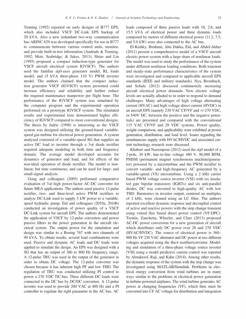
The E190 series EPS, illustrated schematically in Figure 4,is rather conventional using two 3-w 40 kVA 115/200 VAC(phase/line) IDGs powered by respective jet engines eachand a third CF 40 kVA 115/200 VAC generator powered bythe APU. The AC electrical system is thus CF at 400Hz at115/200 VAC with three TRUs (rated at 300 Ampere each)delivering 28 VDC. There are two 22.8 VDC Ni-Cdbatteries, each rated at 27 Ah (616 Wh), powering respectivehot battery buses. Embraer 190 uses 15 kVA 3-w 115/200 VAC 400 Hz RAT installed in a nose as an emergencyin-flight power source. RAT can be deployed manually orautomatically and restowed only on the ground. Abbrevia-tions used in Figure 4 are described in Table 1.
A solid-state static inverter converts 28 VDC into 115VAC using the DC Essential-bus #1 as a source anddelivering conditioned power to the AC Essential-bus orAC Standby-bus. The E-Jet’s EPS provides no-break power
transfer (NBPT) by allowing momentary paralleling (forseveral milliseconds) between two power sources (IDGs,
Figure 4. Embraer 190/195 current production EPS schematics during normal operation.
Table 1E190/195 electrical system abbreviations (source: Embraer).
Abbreviation Description
ICC Integrated Control-CenterRICC Right Integrated Control-CenterLICC Left Integrated Control-CenterEICC* Emergency Integrated Control-CenterAPU Auxiliary Power UnitDC/DC DC-DC Buck ConverterVSCF Variable Speed Constant FrequencyBTC Bus Tie ContactorDCTC DC Tie ContactorTRU Transformer Rectifier UnitBATT Battery
Note: *EICC is normally integrated with LICC.
E. F. C. Freitas & N. E. Daidzic / Journal of Aviation Technology and Engineering 25
GPU, APU) at any possible combination. E-190 also pro-vides connectors for external 115 VAC GPU power source.An external DC GPU rated at 24 to 29 VDC is alsoavailable for APU starting. More details and description ofthe entire E-190/195 can be found in AOM (Embraer,2014), E-190/195 maintenance manual (Embraer, 2015),and other manufacturer’s information.
Proposed Embraer E190/195 VSCF DC-Link EPS Design
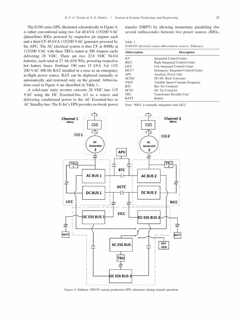
A schematic layout of a new proposed E190/195EPS utilizing DC-Link VSCF is illustrated in Figure 5.SGs rated at 40 kVA and 115/200 VAC were chosen as theprimary electrical power generators. The variable generatorfrequency (VF) is due to the ever-changing angular speed(RPM), which is connected to the engine’s N2-spool (HPspool) shaft via reduction gears (main accessory gearbox).Synchronous generator dq0 mathematical model is des-cribed in Appendix A. The output frequency (Hz) of a 3-wSG (Fitzgerald et al., 2003) links the driver’s RPM (N) andthe fixed number of poles-per-phase (p):
f ~p
2
� �|
N
60ð1Þ
Note that p/2 stands for the number of pole-pairs perphase, while N/60 is the number of revolutions per second(RPS 5 RPM / 60). Desired output voltage is controlled bythe generator field winding excitation governed by a dedi-cated PI controller (see Appendix C for controller tuningmethod). The desired frequency was supplied by a fre-quency generator using sinusoidal PWM and is part ofinverter design. The generator output voltage is negative-feedback controlled in order to maintain constant voltagefor DC-Link.
Two transformer rectifier units (TRU) are used toconvert variable-frequency (VF) 115 VAC at generatoroutput into rectified and filtered 330 VDC. A 12-pulsediode rectifier was utilized because of its advantageousharmonic reduction property over simpler 6-pulse config-uration. The harmonic order can be estimated from,
h~np+1 where p is now the number of pulses-per-cycleand n is an arbitrary integer (Bose, 2002). Similar strategywas used by Eid et al. (2010a, 2010b). For a 12-pulseconfiguration, the 3rd and 5th harmonic orders are notpresent, just 11th and 13th, 23rd and 25th, and so on. In orderto obtain a real 12-pulse rectifier, a phase shift of 30o isrequired. This can be easily accomplished using a D/Y/Dtransformer. The D/Y/D was chosen because it has a usefulproperty of removing triple-order (third, ninth, fifteenth,twenty-first, etc.) odd harmonics (1, 3, 5, 7, etc.).
A 12-pulse forced-commutation controlled-IGBT inver-ter consists of two 6-pulse inverter bridges and was desi-gned to transform 330 VDC into a constant 115 VAC at400 Hz, which is the standard AC electrical supply forE190/195 devices and equipment. In order to obtain 115VAC, a particular minimum input VDC in the inverter isnecessary (Equation 2). Considering the RMS output phasevoltage to be 115 VAC (200 VAC line) and the modulationindex of sinusoidal PWM ma is unity (Bose, 2002; Mohanet al, 2003) results in a minimum of 325 VDC input voltageon DC-Link (Bose, 2002; Eid et al., 2010a, 2010b; Mohanet al, 2003):
VRMS~0:5|ma|VDCffiffiffi
2p ma~
Vr
Vc
ð2Þ
See Appendix D for basic definitions and technicaldetails on PWM. The carrier wave consists of an isoscelestriangular wave (Bose, 2002; Sun, 2012) with voltage Vc
and high frequency fc, while the modulating/reference waveat the fundamental frequency f1 (400 Hz here) has the peakvalue of Vr (Bose, 2002). The PWM of the inverter wascontrolled by a conventional PI controller. This design wasimplemented in our SimulinkH model.
PI and PID (proportional-integral-derivative) controllerswere used to achieve the desired output signals in theinverter, DC-DC Buck converter, and in the field excitationcontrol of SG. In order to obtain constant 330 VDC in aDC-Link channel a dedicated PI controller was implemen-ted. This PI controller governs the AC SG output voltage. Ifthe increased load induces voltage drop on DC-Link, the
Figure 5. Proposed Embraer E190/195 VSCF DC-Link for AC-DC-AC power generation, conversion, and distribution.
26 E. F. C. Freitas & N. E. Daidzic / Journal of Aviation Technology and Engineering
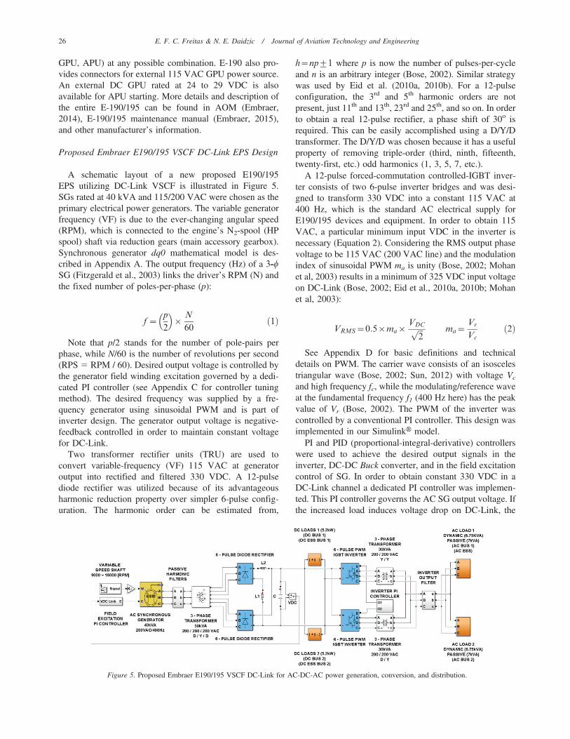
voltage of AC generator will increase to compensate for it.The proportional Kp and the integral Ki gains were tuned inorder to obtain a satisfactory transient and steady-stateperformance (Nise, 2011). A schematic of AC SG fieldexcitation governing using PI controller is illustrated inFigure 6. Consult Appendix C for more details on tuning ofPI and PID controllers. Three-phase passive harmonic filterson AC SG output are depicted in Figure 7.
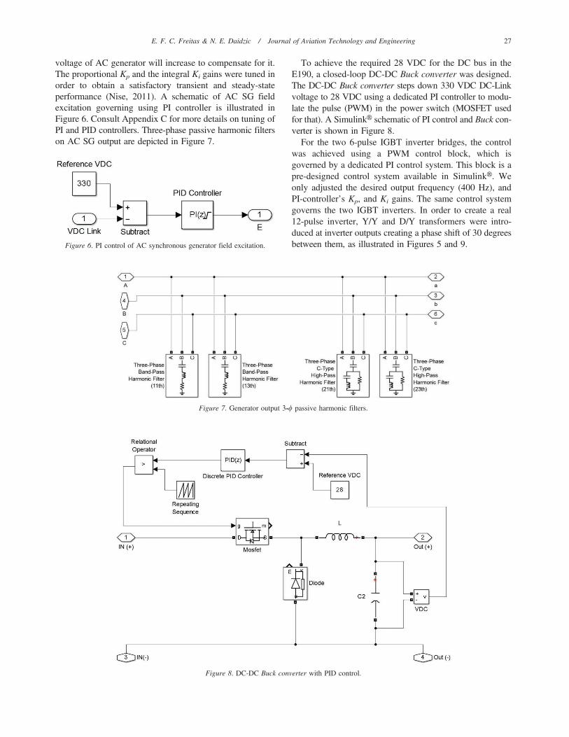
To achieve the required 28 VDC for the DC bus in theE190, a closed-loop DC-DC Buck converter was designed.The DC-DC Buck converter steps down 330 VDC DC-Linkvoltage to 28 VDC using a dedicated PI controller to modu-late the pulse (PWM) in the power switch (MOSFET usedfor that). A SimulinkH schematic of PI control and Buck con-verter is shown in Figure 8.
For the two 6-pulse IGBT inverter bridges, the controlwas achieved using a PWM control block, which isgoverned by a dedicated PI control system. This block is apre-designed control system available in SimulinkH. Weonly adjusted the desired output frequency (400 Hz), andPI-controller’s Kp, and Ki gains. The same control systemgoverns the two IGBT inverters. In order to create a real12-pulse inverter, Y/Y and D/Y transformers were intro-duced at inverter outputs creating a phase shift of 30 degreesbetween them, as illustrated in Figures 5 and 9.Figure 6. PI control of AC synchronous generator field excitation.
Figure 7. Generator output 3-w passive harmonic filters.
Figure 8. DC-DC Buck converter with PID control.
E. F. C. Freitas & N. E. Daidzic / Journal of Aviation Technology and Engineering 27
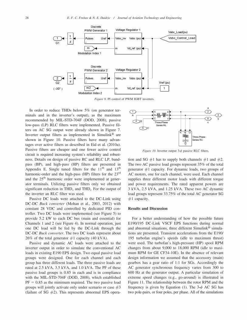
In order to reduce THDs below 5% (on generator ter-minals and in the inverter’s output), as the maximumrecommended by MIL-STD-704F (DOD, 2008), passivelow-pass (LP) RLC filters were implemented. Passive fil-ters on AC SG output were already shown in Figure 7.Inverter output filters as implemented in SimulinkH areshown in Figure 10. Passive filters have many advan-tages over active filters as described in Eid et al. (2010a).Passive filters are cheaper and one fewer active controlcircuit is required increasing system’s reliability and robust-ness. Details on design of passive RC and RLC LP, band-pass (BP), and high-pass (HP) filters are presented inAppendix E. Single tuned filters for the 11th and 13th
harmonic-order and the high-pass (HP) filters for the 23rd
and the 25th harmonic order were implemented at gener-ator terminals. Utilizing passive filters only we obtainedsignificant reduction in THDv and THDi. For the output ofthe inverter an RLC filter was used.
Passive DC loads were attached to the DC-Link usingDC-DC Buck converter (Mohan et al., 2003, 2012) withconstant 28 VDC and controlled by dedicated PID con-troller. Two DC loads were implemented (see Figure 5) toprovide 5.2 kW to each DC bus (main and essential) forChannels 1 and 2 (see Figure 4). In normal operation, justone DC load will be fed by the DC-Link through theDC-DC Buck converter. The two DC loads represent about26% of the total generator #1 capacity (40 kVA).
Passive and dynamic AC loads were attached to theinverter output in order to simulate the conventional ACloads in existing E190 EPS design. Two equal passive loadgroups were designed. One for each channel and eachgroup has three different loads. The three passive loads arerated at 2.5 kVA, 3.5 kVA, and 1.0 kVA. The PF of thesepassive load groups is 0.85 in each and is in compliancewith the MIL-STD-704F (DOD, 2008), which establishedPF 5 0.85 as the minimum required. The two passive loadgroups will jointly activate only under scenario or case #3(failure of SG #2). This represents abnormal EPS opera-
tion and SG #1 has to supply both channels #1 and #2.The two AC passive load groups represent 35% of the totalgenerator #1 capacity. For dynamic loads, two groups ofAC motors, one for each channel, were used. Each channelsupplies three different motor loads with different torqueand power requirements. The rated apparent powers are3 kVA, 2.5 kVA, and 1.25 kVA. These two AC dynamicload groups represent 33.75% of the total AC generator SG#1 capacity.
Results and Discussion
For a better understanding of how the possible futureE190/195 DC-Link VSCF EPS functions during normaland abnormal situations, three different SimulinkH simula-tions are presented. Transient accelerations from the E190/195 turbofan engine’s speeds (idle to maximum thrust)were used. The turbofan’s high-pressure (HP) spool RPMchanges from about 9,000 to 18,000 RPM (idle to maxi-mum RPM for GE CF34-10E). In the absence of relevantdesign information we assumed that the accessory (main)gearbox has a gear ratio of 1:1 for SGs. Accordingly theAC generator synchronous frequency varies from 300 to600 Hz at the generator output. A particular simulation ofextreme speed changes (e.g., go-around) is illustrated inFigure 11. The relationship between the rotor RPM and thefrequency is given by Equation (1). The 3-w AC SG hastwo pole-pairs, or four poles, per phase. All of the simulations
Figure 9. PI control of PWM IGBT inverters.
Figure 10. Inverter output 3-w passive RLC filters.
28 E. F. C. Freitas & N. E. Daidzic / Journal of Aviation Technology and Engineering
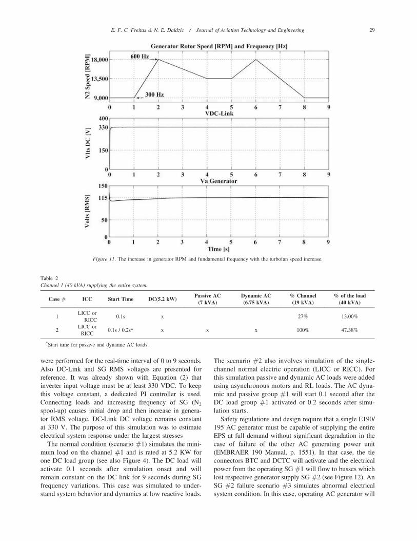
were performed for the real-time interval of 0 to 9 seconds.Also DC-Link and SG RMS voltages are presented forreference. It was already shown with Equation (2) thatinverter input voltage must be at least 330 VDC. To keepthis voltage constant, a dedicated PI controller is used.Connecting loads and increasing frequency of SG (N2
spool-up) causes initial drop and then increase in genera-tor RMS voltage. DC-Link DC voltage remains constantat 330 V. The purpose of this simulation was to estimateelectrical system response under the largest stresses
The normal condition (scenario #1) simulates the mini-mum load on the channel #1 and is rated at 5.2 KW forone DC load group (see also Figure 4). The DC load willactivate 0.1 seconds after simulation onset and willremain constant on the DC link for 9 seconds during SGfrequency variations. This case was simulated to under-stand system behavior and dynamics at low reactive loads.
The scenario #2 also involves simulation of the single-channel normal electric operation (LICC or RICC). Forthis simulation passive and dynamic AC loads were addedusing asynchronous motors and RL loads. The AC dyna-mic and passive group #1 will start 0.1 second after theDC load group #1 activated or 0.2 seconds after simu-lation starts.
Safety regulations and design require that a single E190/195 AC generator must be capable of supplying the entireEPS at full demand without significant degradation in thecase of failure of the other AC generating power unit(EMBRAER 190 Manual, p. 1551). In that case, the tieconnectors BTC and DCTC will activate and the electricalpower from the operating SG #1 will flow to busses whichlost respective generator supply SG #2 (see Figure 12). AnSG #2 failure scenario #3 simulates abnormal electricalsystem condition. In this case, operating AC generator will
Figure 11. The increase in generator RPM and fundamental frequency with the turbofan speed increase.
Table 2Channel 1 (40 kVA) supplying the entire system.
Case # ICC Start Time DC(5.2 kW)Passive AC
(7 kVA)Dynamic AC(6.75 kVA)
% Channel(19 kVA)
% of the load(40 kVA)
1LICC or
RICC0.1s x 27% 13.00%
2LICC or
RICC0.1s / 0.2s* x x x 100% 47.38%
*Start time for passive and dynamic AC loads.
E. F. C. Freitas & N. E. Daidzic / Journal of Aviation Technology and Engineering 29
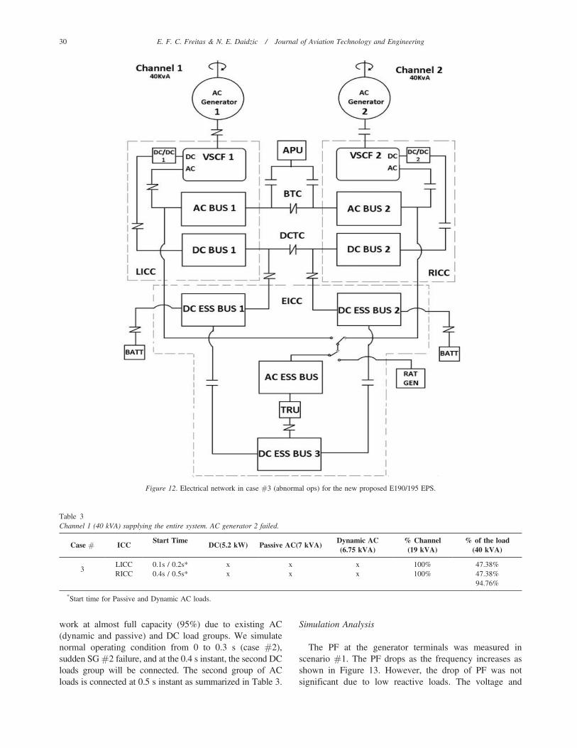
work at almost full capacity (95%) due to existing AC(dynamic and passive) and DC load groups. We simulatenormal operating condition from 0 to 0.3 s (case #2),sudden SG #2 failure, and at the 0.4 s instant, the second DCloads group will be connected. The second group of ACloads is connected at 0.5 s instant as summarized in Table 3.
Simulation Analysis
The PF at the generator terminals was measured inscenario #1. The PF drops as the frequency increases asshown in Figure 13. However, the drop of PF was notsignificant due to low reactive loads. The voltage and
Table 3Channel 1 (40 kVA) supplying the entire system. AC generator 2 failed.
Case # ICCStart Time
DC(5.2 kW) Passive AC(7 kVA)Dynamic AC(6.75 kVA)
% Channel(19 kVA)
% of the load(40 kVA)
3LICC 0.1s / 0.2s* x x x 100% 47.38%RICC 0.4s / 0.5s* x x x 100% 47.38%
94.76%
*Start time for Passive and Dynamic AC loads.
Figure 12. Electrical network in case #3 (abnormal ops) for the new proposed E190/195 EPS.
30 E. F. C. Freitas & N. E. Daidzic / Journal of Aviation Technology and Engineering

current THDs were measured at the generator terminalsand at the output of the inverter where the AC loads wereattached. The results for THDv and THDi are shown inFigures 14 and 15, respectively. Theoretical details on PFdefinition and calculations are given in Appendix A. Thereactive power (Q) is measured in Volt-Ampere-Reactive(VAR) and is proportional to AC frequency implying thatincreasing the frequency the reactive power will increase aswell, lagging or leading the voltage. In case #1, wherelow reactive elements are connected to the system and thereal power (P in W) remains constant, the PF (PF 5 P/S)exhibits very shallow decrease with increasing frequency.On the other hand, in cases #2 and #3, where relativelyhigh reactive elements (asynchronous motors and passiveRL loads) are connected, the PF exhibits more signifi-cant drop with increasing frequency. Transformer voltageregulation (200/280/280) and THD filters were utilized toimprove PF.
In all cases (scenarios), the highest PF consistentlyoccurs at the minimum SG frequency of 300 Hz. Thelowest PF of 0.85 was experienced in case #3 at thehighest frequency of 600 Hz. The AC passive loads havethe PF of 0.85 and the AC dynamic load of 0.97 in allsimulated scenarios. Thus the total PF of AC loads isaround 0.91. This PF contributes to the decrease of PF onSG terminals. High THD can cause high temperatures inthe core of the generators and transformers and it can causeinterference in transmission lines because of the possibleresonance problem. The THD can be alleviated by active orpassive filter systems. Passive filters to reduce voltage(THDv) and current (THDi) harmonics were implementedhere (see Appendix E for more details). The MIL-STD-704F defines acceptable THD as being less than 5%.The maximum value of THDv was only 1.4% for case#3 as seen in Figure 14. The THDi (Figure 15) showedhigh frequency and load sensitivity. As the load and
Figure 13. PFs for all three simulated cases (scenarios) at generator terminals.
Figure 14. THDv at generator terminals.
E. F. C. Freitas & N. E. Daidzic / Journal of Aviation Technology and Engineering 31

frequency increased, THDi decreased significantly. Part ofthe reason is the use of passive RLC filters at generatorterminals intended to reduce the main harmonics (11th and
13th, and 23rd and 25th). A phase shift between the currentand voltage at four discrete generator frequencies is shownin Figure 16.
Figure 15. THDi at generator terminals.
Figure 16. Shift between line voltages and currents on generator terminals for PF , 1 at four discrete frequencies (300, 400, 500, and 600 Hz).
32 E. F. C. Freitas & N. E. Daidzic / Journal of Aviation Technology and Engineering
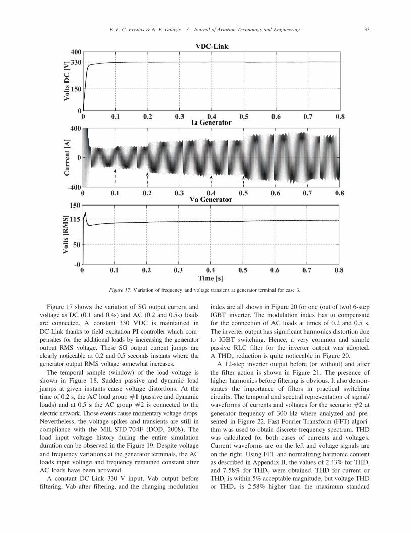
Figure 17 shows the variation of SG output current andvoltage as DC (0.1 and 0.4s) and AC (0.2 and 0.5s) loadsare connected. A constant 330 VDC is maintained inDC-Link thanks to field excitation PI controller which com-pensates for the additional loads by increasing the generatoroutput RMS voltage. These SG output current jumps areclearly noticeable at 0.2 and 0.5 seconds instants where thegenerator output RMS voltage somewhat increases.
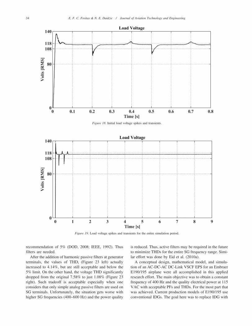
The temporal sample (window) of the load voltage isshown in Figure 18. Sudden passive and dynamic loadjumps at given instants cause voltage distortions. At thetime of 0.2 s, the AC load group #1 (passive and dynamicloads) and at 0.5 s the AC group #2 is connected to theelectric network. Those events cause momentary voltage drops.Nevertheless, the voltage spikes and transients are still incompliance with the MIL-STD-704F (DOD, 2008). Theload input voltage history during the entire simulationduration can be observed in the Figure 19. Despite voltageand frequency variations at the generator terminals, the ACloads input voltage and frequency remained constant afterAC loads have been activated.
A constant DC-Link 330 V input, Vab output beforefiltering, Vab after filtering, and the changing modulation
index are all shown in Figure 20 for one (out of two) 6-stepIGBT inverter. The modulation index has to compensatefor the connection of AC loads at times of 0.2 and 0.5 s.The inverter output has significant harmonics distortion dueto IGBT switching. Hence, a very common and simplepassive RLC filter for the inverter output was adopted.A THDv reduction is quite noticeable in Figure 20.
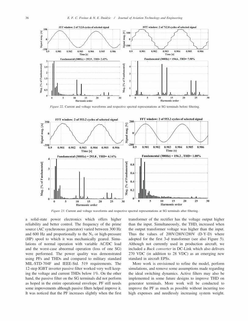
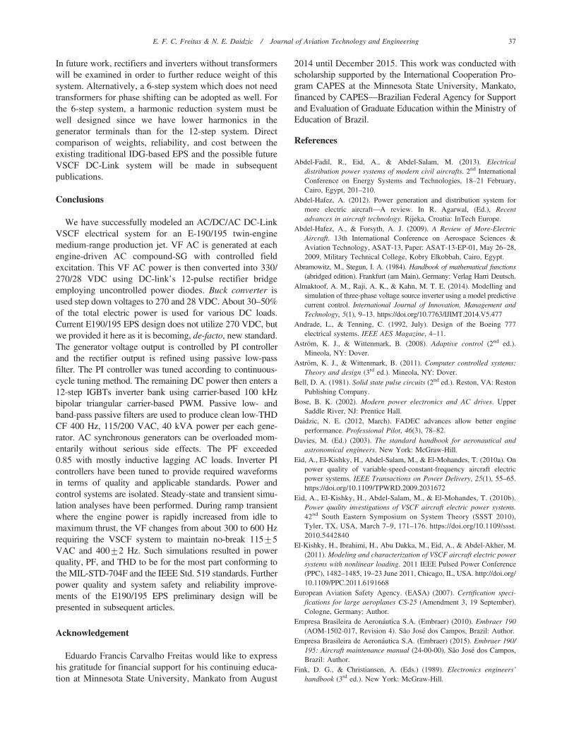
A 12-step inverter output before (or without) and afterthe filter action is shown in Figure 21. The presence ofhigher harmonics before filtering is obvious. It also demon-strates the importance of filters in practical switchingcircuits. The temporal and spectral representation of signal/waveforms of currents and voltages for the scenario #2 atgenerator frequency of 300 Hz where analyzed and pre-sented in Figure 22. Fast Fourier Transform (FFT) algori-thm was used to obtain discrete frequency spectrum. THDwas calculated for both cases of currents and voltages.Current waveforms are on the left and voltage signals areon the right. Using FFT and normalizing harmonic contentas described in Appendix B, the values of 2.43% for THDi
and 7.58% for THDv were obtained. THD for current orTHDi is within 5% acceptable magnitude, but voltage THDor THDv is 2.58% higher than the maximum standard
Figure 17. Variation of frequency and voltage transient at generator terminal for case 3.
E. F. C. Freitas & N. E. Daidzic / Journal of Aviation Technology and Engineering 33
recommendation of 5% (DOD, 2008; IEEE, 1992). Thusfilters are needed.
After the addition of harmonic passive filters at generatorterminals, the values of THDi (Figure 23 left) actuallyincreased to 4.14%, but are still acceptable and below the5% limit. On the other hand, the voltage THD significantlydropped from the original 7.58% to just 1.08% (Figure 23right). Such tradeoff is acceptable especially when oneconsiders that only simple analog passive filters are used onSG terminals. Unfortunately, the situation gets worse withhigher SG frequencies (400–600 Hz) and the power quality
is reduced. Thus, active filters may be required in the futureto minimize THDs for the entire SG frequency range. Simi-lar effort was done by Eid et al. (2010a).
A conceptual design, mathematical model, and simula-tion of an AC-DC-AC DC-Link VSCF EPS for an EmbraerE190/195 airplane were all accomplished in this appliedresearch effort. The main objective was to obtain a constantfrequency of 400 Hz and the quality electrical power at 115VAC with acceptable PFs and THDs. For the most part thatwas achieved. Current production models of E190/195 useconventional IDGs. The goal here was to replace IDG with
Figure 18. Initial load voltage spikes and transients.
Figure 19. Load voltage spikes and transients for the entire simulation period.
34 E. F. C. Freitas & N. E. Daidzic / Journal of Aviation Technology and Engineering
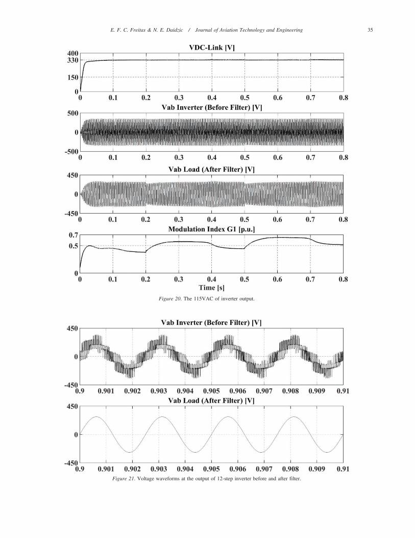
Figure 20. The 115VAC of inverter output.
Figure 21. Voltage waveforms at the output of 12-step inverter before and after filter.
E. F. C. Freitas & N. E. Daidzic / Journal of Aviation Technology and Engineering 35
a solid-state power electronics which offers higherreliability and better control. The frequency of the primesource (AC synchronous generator) varied between 300 Hzand 600 Hz and proportionally to the N2 or high-pressure(HP) spool to which it was mechanically geared. Simu-lations of normal operation with variable AC/DC loadand the worst-case abnormal operation (loss of one SG)were performed. The power quality was demonstratedusing PFs and THDs and compared to military standardMIL-STD-704F and IEEE-Std. 519 requirements. The12-step IGBT inverter passive filter worked very well keep-ing the voltage and current THDs below 1%. On the otherhand, the passive filter on the SG terminals did not performas hoped in the entire operational envelope. PF still needssome improvements although passive filters helped improve it.It was noticed that the PF increases slightly when the first
transformer of the rectifier has the voltage output higherthan the input. Simultaneously, the THDi increased whenthe output transformer voltage was higher than the input.Thus the values of 200V/280V/280V (D-Y-D) whereadopted for the first 3-w transformer (see also Figure 5).Although not currently used in production aircraft, weincluded a Buck converter in DC-Link which also delivers270 VDC (in addition to 28 VDC) as an emerging newstandard in aircraft EPSs.
More work is envisioned to refine the model, performsimulations, and remove some assumptions made regardingthe ideal switching dynamics. Active filters may also beimplemented in some future designs to improve THD ongenerator terminals. More work will be conducted toimprove the PF as much as possible without incurring toohigh expenses and needlessly increasing system weight.
Figure 22. Current and voltage waveforms and respective spectral representations at SG terminals before filtering.
Figure 23. Current and voltage waveforms and respective spectral representations at SG terminals after filtering.
36 E. F. C. Freitas & N. E. Daidzic / Journal of Aviation Technology and Engineering
In future work, rectifiers and inverters without transformerswill be examined in order to further reduce weight of thissystem. Alternatively, a 6-step system which does not needtransformers for phase shifting can be adopted as well. Forthe 6-step system, a harmonic reduction system must bewell designed since we have lower harmonics in thegenerator terminals than for the 12-step system. Directcomparison of weights, reliability, and cost between theexisting traditional IDG-based EPS and the possible futureVSCF DC-Link system will be made in subsequentpublications.
Conclusions
We have successfully modeled an AC/DC/AC DC-LinkVSCF electrical system for an E-190/195 twin-enginemedium-range production jet. VF AC is generated at eachengine-driven AC compound-SG with controlled fieldexcitation. This VF AC power is then converted into 330/270/28 VDC using DC-link’s 12-pulse rectifier bridgeemploying uncontrolled power diodes. Buck converter isused step down voltages to 270 and 28 VDC. About 30–50%of the total electric power is used for various DC loads.Current E190/195 EPS design does not utilize 270 VDC, butwe provided it here as it is becoming, de-facto, new standard.The generator voltage output is controlled by PI controllerand the rectifier output is refined using passive low-passfilter. The PI controller was tuned according to continuous-cycle tuning method. The remaining DC power then enters a12-step IGBTs inverter bank using carrier-based 100 kHzbipolar triangular carrier-based PWM. Passive low- andband-pass passive filters are used to produce clean low-THDCF 400 Hz, 115/200 VAC, 40 kVA power per each gene-rator. AC synchronous generators can be overloaded mom-entarily without serious side effects. The PF exceeded0.85 with mostly inductive lagging AC loads. Inverter PIcontrollers have been tuned to provide required waveformsin terms of quality and applicable standards. Power andcontrol systems are isolated. Steady-state and transient simu-lation analyses have been performed. During ramp transientwhere the engine power is rapidly increased from idle tomaximum thrust, the VF changes from about 300 to 600 Hzrequiring the VSCF system to maintain no-break 115¡5VAC and 400¡2 Hz. Such simulations resulted in powerquality, PF, and THD to be for the most part conforming tothe MIL-STD-704F and the IEEE Std. 519 standards. Furtherpower quality and system safety and reliability improve-ments of the E190/195 EPS preliminary design will bepresented in subsequent articles.
Acknowledgement
Eduardo Francis Carvalho Freitas would like to expresshis gratitude for financial support for his continuing educa-tion at Minnesota State University, Mankato from August
2014 until December 2015. This work was conducted withscholarship supported by the International Cooperation Pro-gram CAPES at the Minnesota State University, Mankato,financed by CAPES—Brazilian Federal Agency for Supportand Evaluation of Graduate Education within the Ministry ofEducation of Brazil.
References
Abdel-Fadil, R., Eid, A., & Abdel-Salam, M. (2013). Electricaldistribution power systems of modern civil aircrafts. 2nd InternationalConference on Energy Systems and Technologies, 18–21 February,Cairo, Egypt, 201–210.
Abdel-Hafez, A. (2012). Power generation and distribution system formore electric aircraft—A review. In R. Agarwal, (Ed.), Recentadvances in aircraft technology. Rijeka, Croatia: InTech Europe.
Abdel-Hafez, A., & Forsyth, A. J. (2009). A Review of More-ElectricAircraft. 13th International Conference on Aerospace Sciences &Aviation Technology, ASAT-13, Paper: ASAT-13-EP-01, May 26–28,2009, Military Technical College, Kobry Elkobbah, Cairo, Egypt.
Abramowitz, M., Stegun, I. A. (1984). Handbook of mathematical functions(abridged edition). Frankfurt (am Main), Germany: Verlag Harri Deutsch.
Almaktoof, A. M., Raji, A. K., & Kahn, M. T. E. (2014). Modelling andsimulation of three-phase voltage source inverter using a model predictivecurrent control. International Journal of Innovation, Management andTechnology, 5(1), 9–13. https://doi.org/10.7763/IJIMT.2014.V5.477
Andrade, L., & Tenning, C. (1992, July). Design of the Boeing 777electrical systems. IEEE AES Magazine, 4–11.
Astrom, K. J., & Wittenmark, B. (2008). Adaptive control (2nd ed.).Mineola, NY: Dover.
Astrom, K. J., & Wittenmark, B. (2011). Computer controlled systems:Theory and design (3rd ed.). Mineola, NY: Dover.
Bell, D. A. (1981). Solid state pulse circuits (2nd ed.). Reston, VA: RestonPublishing Company.
Bose, B. K. (2002). Modern power electronics and AC drives. UpperSaddle River, NJ: Prentice Hall.
Daidzic, N. E. (2012, March). FADEC advances allow better engineperformance. Professional Pilot, 46(3), 78–82.
Davies, M. (Ed.) (2003). The standard handbook for aeronautical andastronomical engineers. New York: McGraw-Hill.
Eid, A., El-Kishky, H., Abdel-Salam, M., & El-Mohandes, T. (2010a). Onpower quality of variable-speed-constant-frequency aircraft electricpower systems. IEEE Transactions on Power Delivery, 25(1), 55–65.https://doi.org/10.1109/TPWRD.2009.2031672
Eid, A., El-Kishky, H., Abdel-Salam, M., & El-Mohandes, T. (2010b).Power quality investigations of VSCF aircraft electric power systems.42nd South Eastern Symposium on System Theory (SSST 2010),Tyler, TX, USA, March 7–9, 171–176. https://doi.org/10.1109/ssst.2010.5442840
El-Kishky, H., Ibrahimi, H., Abu Dakka, M., Eid, A., & Abdel-Akher, M.(2011). Modeling and characterization of VSCF aircraft electric powersystems with nonlinear loading. 2011 IEEE Pulsed Power Conference(PPC), 1482–1485, 19–23 June 2011, Chicago, IL, USA. http://doi.org/10.1109/PPC.2011.6191668
European Aviation Safety Agency. (EASA) (2007). Certification speci-fications for large aeroplanes CS-25 (Amendment 3, 19 September).Cologne, Germany: Author.
Empresa Brasileira de Aeronautica S.A. (Embraer) (2010). Embraer 190(AOM-1502-017, Revision 4). Sao Jose dos Campos, Brazil: Author.
Empresa Brasileira de Aeronautica S.A. (Embraer) (2015). Embraer 190/195: Aircraft maintenance manual (24-00-00). Sao Jose dos Campos,Brazil: Author.
Fink, D. G., & Christiansen, A. (Eds.) (1989). Electronics engineers’handbook (3rd ed.). New York: McGraw-Hill.
E. F. C. Freitas & N. E. Daidzic / Journal of Aviation Technology and Engineering 37

Fitzgerald, A. E., Kingsley, C. Jr., & Umans, S. D. (2003). Electricmachinery (6th ed.). New York: McGraw-Hill.
Gong, G., Heldwein, M. L., Drofenik, U., Minibock, J., Mino, K., & KolarJ. W. (2005). Comparative evaluation of three-phase high-power-factorAC-DC converter concepts for application in future more electricaircraft. IEEE Transactions on Industrial Electronics, 52(3), 727–737.http://doi.org/10.1109/TIE.2005.843957
Gottlieb, I. M. (1994). Electric motors and control techniques (2nd ed.).New York: McGraw-Hill.
Grigsby, L. L. (Ed.) (2007). Power systems. Boca Raton, FL: CRC Press/Taylor & Francis.
Hamming, R. W. (1998). Digital filters (3rd ed.). Mineola, NY: Dover.Hart, D. W. (2011). Power electronics. New York: McGraw-Hill.Holtz, J. (1994). Pulsewidth modulation for electronic power conversion.
Proceedings of the IEEE, 82(8), 1194–1214. https://doi.org/10.1109/5.301684
Institute of Electrical and Electronics Engineers (IEEE). (1992).Recommended practices and requirements for harmonic control inelectrical power systems (ANSI/IEEE Std. 519). Retrieved from http://standards.ieee.org/
Jadric, I. (1998). Modeling and control of a synchronous generator withelectronic load (Master’s thesis, Virginia Polytechnic Institute andState University). Blacksburg, Virginia: Author.
Jeppesen. (2007). Electrics (JAA ATPL Training Ed. 2 JAR Ref 0121 02).Neu-Isenburg, Germany: Author.
Karris, S. T. (2008). Introduction to SIMULINKH with engineeringapplications (2nd ed.). Fremont, CA: Orchard Publications.
Khaburi, D. A., & Nazempour, A. (2012). Design and simulation of aPWM rectifier connected to a PM generator of micro turbine unit.Scientia Iranica, 19(3), 820–828.
Kilian, C. T. (2006). Modern control technology (3rd ed.). Clifton Park,NY: Delmar.
Kirk, D. E. (2004). Optimal control theory: An introduction. Mineola, NY:Dover.
Luo, F. L., & Ye, H. (2010). Power electronics: Advanced conversiontechnologies. Boca Raton, FL: CRC Press/Taylor & Francis.
Malinowski, M., Milczarek, A., Kot, R., Goryca, Z., & Szuster, J T.,(2015, September). Optimized energy conversion systems for smallwind turbines. IEEE Power Electronic Magazine, 2(3), 16–30. https://doi.org/10.1109/MPEL.2015.2447631
Moir, I., & Seabridge, A. (2008). Aircraft systems (3rd ed.). New York:John Wiley & Sons.
Moir, I., & Seabridge, A. (2013). Design and development of aircraftsystems (2nd ed.). New York: John Wiley & Sons.
Moir, I., Seabridge, A., & Jukes, M. (2013). Civil avionics systems (2nd
ed.). New York: John Wiley & Sons.Mohan, N. (2012). Power electronics: A first course. New York: John
Wiley & Sons.Mohan, N., Undeland, T. M., & Robbins, W. P. (2003). Power electronics: Con-
verters, applications and design (3rd ed.). New York: John Wiley & Sons.Nahvi, M. & Edminister, J. (2003). Electric circuits (4th ed.). New York:
McGraw-Hill.Netushil, A. (Ed.). 1978). Theory of automatic control. Moscow, Russia:
MIR Publishers.Nise, N. S. (2011). Control systems engineering (6th ed.). New York: John
Wiley & Sons.Nya, B. H., Brombach, J., & Schulz, D. (2012). Benefits of higher voltage
levels in aircraft electrical systems. In IEEE electrical systems foraircraft, railway and ship propulsion (ESARS), October 16–18, 2012,Bologna, Italy. https://doi.org/10.1109/ESARS.2012.6387381
Ogata, K. (2004). System dynamics (4th ed.). Upper Saddle River, NJ:Pearson Prentice Hall.
Phillips, C. L., & Parr, J. M. (1999). Signals, systems, and transforms(2nd ed.). Upper Saddle River, NJ: Prentice-Hall.
Rahal, A. (1991). Design of static frequency converter suitable for aircraft powersystems (Master’s thesis, Dublin City University). Dublin, Ireland: Author.
Shiao, Y. S., & Lin, C. E. (1995). A prototype induction generator VSCFsystem for aircraft. International IEEE/IAS Conference on IndustrialAutomation and Control: Emerging Technologies, 148–155, 22–27May, 1995. Taipei. https://doi.org/10.1109/IACET.1995.527554
Sun, J. (2012). Pulse-width modulation. In F. Vasca &L. Iannelli (Eds),Dynamics and control of switched electronic systems (Chapter 2).London: Springer-Verlag.
Tewari, A. (2005). Modern control design with MATLAB and SIMULINK.Chichester, England: John Wiley & Sons.
Tolstov, G. P. (1976). Fourier series (translated from Russian). New York:Dover.
Trentin, A., Zanchetta, P., Wheeler, P., & Clare, J. (2014). Powerconversion for a novel AC/DC aircraft electrical distribution system.IET Electrical Systems in Transportation, 4(2), 29–37. https://doi.org/10.1049/iet-est.2013.0005
US Department of Defense. (2008). Aircraft electric power characteristics(MIL-STD-704F). Lakehurst, NJ: Author.
US Department of Transportation, Federal Aviation Administration.(2014). Part 25, Airworthiness standards: Transport category air-planes. Washington, DC: Author.
Vadher, V. V., Smith, L. R., & Williams, S. (1986). Mathematical model-ling of a VSCF aircraft generating system. IEEE Transactions onAerospace and Electronics (IEEE AES), 22(5), 573–582. https://doi.org/10.1109/taes.1986.310724
Wild, T. W. (2008). Transport category aircraft systems (3rd ed.).Englewood, CO: Jeppesen.
Appendix A
Modeling of Synchronous Generator
We are using synchronous generator (SG) equivalentcircuit model in a rotating dq0 frame-of-reference (Bose,2002; Eid et al., 2010a; Fitzgerald et al., 2003; Jadric,1998; Khaburi & Nazempour, 2012). Transformation fromthe stationary 3-w stator quantities into direct (d) andperpendicular quadrature (q) axis is performed in which thed-axis is aligned with the field-winding axis and is rotating.Direct and inverse transformation (often referred to asBlondel or Park’s) between stator’s and rotating dq0quantities (flux, current, voltage) is symbolically written as(Fitzgerald et al., 2003):
Sd
Sq
S0
264
375~T
Sa
Sb
Sc
264
375
Sa
Sb
Sc
264
375~T{1
Sd
Sq
S0
264
375 ðA1Þ
The transformation matrix (and its inverse) depends onthe electrical angle he between the rotor direct or d-axis andthe stator’s stationary a-phase axis. The zero-sequencecomponent 0 in dq0 method is required to yield uniquetransformation of the 3-w stator quantities as it correspondsto components of armature current which produce no netflux linking the rotor circuits. Under balanced 3-w condi-tions there are no zero-sequence components (Fitzgeraldet al., 2003). Only instantaneous and not RMS quantitiesare considered in dq0 transformation (Fitzgerald et al.,2003). The damper windings, if present, are short circuited
38 E. F. C. Freitas & N. E. Daidzic / Journal of Aviation Technology and Engineering

(Jadric, 1998). The SG model as used in this study can benow described with a system of nonlinear ordinary dif-ferential equations (ODE):
1. Torque balance for rotor:
Jdvm
dt~tm{te{B:vm ðA2Þ
where,
dhm
dt~vm vm~
2
pve te~
3
2
p
2
� �: ld iq{lqid� �
ðA3Þ
2. Stator equations:
vd~{Rsid{velqzdld
dt
vq~{Rsiqzveldzdlq
dt
ðA4Þ
where,
ld~{ LlszLmdð Þ:idzLmd ifdzikd
� �lq~{ LlszLmq
� �:iqzLmqikq
ðA5Þ
3. Field winding equation:
vfd~Rfdifd{Lmd
did
dtz LlfdzLmd
� � difd
dtzLmd
dikd
dtðA6Þ
4. Damper winding equations:
0~Rkdikd{Lmd
did
dtzLmd
difd
dtz LlkdzLmdð Þ dikd
dt
0~Rkqikq{Lmq
diq
dtz LlkqzLmq
� � dikq
dt
ðA7Þ
Variables and parameters used in dq0 model are (Bose,2002; Eid et al., 2010a; Fitzgerald et al, 2003; Jadric,1998):
N vm: rotor speed (mechanical, rad/s),N ve: rotor speed (electrical, rad/s),N hm: rotor angle (mechanical, rad),N te: electromagnetic torque (Nm),N tm: mechanical torque supplied to generator by
prime mover (Nm),N p: number of poles,N B: coefficient of rotational friction (mechanical
loss),N J: rotor’s moment of inertia (kg m2),N vd : armature d axis terminal voltage,N vq: armature q axis terminal voltage,N id : armature d axis terminal current,N iq: armature q axis terminal current,
N vfd : field winding terminal voltage (reflected to thestator),
N ifd : field winding terminal current (reflected to thestator),
N ikd : d axis damper winding current (reflected to thestator),
N ikq: q axis damper winding current (reflected to thestator),
N ld : total armature flux in d axis,N lq: total armature flux in q axis,N Rs: armature phase resistance,N Rfd : field winding resistance (reflected to the
stator),N Lls: armature phase leakage inductance,N Llfd : field winding leakage inductance (reflected to
the stator),N Lmd : d axis coupling inductance,N Rkd : d axis damper winding resistance (reflected to
the stator),N Llkd : d axis damper winding leakage inductance
(reflected to the stator),N Lmq: q axis coupling inductance,N Rkq: q axis damper winding resistance (reflected to
the stator),N Llkq: q axis damper winding leakage inductance
(reflected to the stator).
Appendix B
Power Quality and Computation Essentials
Periodic currents with a period T can be presentedmost generally in terms of the Fourier series (Hart, 2011;Nahvi & Edminister, 2003, Mohan et al., 2003, Phillips &Parr, 1999):
v tð Þ~V0zP?n~1
Vn sin nv tzhnð Þ
i tð Þ~I0zX?m~1
Im sin mv tzymð Þ ðB1Þ
The effective or root-mean-square (RMS) values ofvoltage and current in a single-harmonic sinusoidal signalare defined as:
Veff ~VRMS~
ffiffiffiffiffiffiffiffiffiffiffiffiffiffiffiffiffiffiffiffiffiffiffi1
T
ðT0
v2 tð Þ dt
vuuut ~Vmaxffiffiffi
2p
Ieff ~IRMS~
ffiffiffiffiffiffiffiffiffiffiffiffiffiffiffiffiffiffiffiffiffiffi1
T
ðT0
i2 tð Þ dt
vuuut ~Imaxffiffiffi
2p &0:707:Imax ðB2Þ
E. F. C. Freitas & N. E. Daidzic / Journal of Aviation Technology and Engineering 39
More generally, for multi-harmonic periodic orthogonalcurrents:
VRMS~
ffiffiffiffiffiffiffiffiffiffiffiffiffiffiffiffiffiffiffiffiffiffiPNn~1
V2n,RMS
sIRMS~
ffiffiffiffiffiffiffiffiffiffiffiffiffiffiffiffiffiffiffiffiffiPNn~1
I2n,RMS
sðB3Þ
Using Equation (A1), the average or real power isdefined as:
Pavg~1
T
ðT0
v tð Þ:i tð Þ dt~1
T
ðT0
V0zX?n~1
Vn sin nv tzhnð Þ" #
:
I0zX?m~1
Im sin mv tzymð Þ" #
dt ðB4Þ
Using the property of orthogonal basis functions (alln=m components vanishing) and the phase, wn~hn{yn
(Nahvi & Edminister, 2003; Phillips & Parr, 1999):
Pavg~vp tð Þw~1
T
ðT0
v tð Þ:i tð Þ dt~V0I0z
X?n~1
Vn,RMSIn,RMS cos wn~P0zX?n~1
Pn ðB5Þ
The relationship between the amplitudes (maximumvalues) and the RMS values is given by Equation (B2). InDC systems onlyV0,I0=0, Vn,In~0, P0~V0I0=0. In asingle-harmonic sinusoidal AC source (V1=0, Vn~0) andDC components zero (V0~0), applied to nonlinear loadwith complex current waveform, the real power is expres-sed as (w1~h1{y1):
P~ 1T
ÐT0
V1 sin nv tzhnð Þ: I0zP?
n~1
In sin nv tzynð Þ� �
dt~
V1,RMSI1,RMS cos w1 ðB6Þ
In electrical network with many elements of resistance(R), capacitance (C), and inductance (L), the impedanceand the phase shift with inductive (XL) and capacitive (XC)reactances are:
Z~Rzj XL{XCð Þ~ Zj j:ejw~ Zj j%w
Z~ Zj j~ffiffiffiffiffiffiffiffiffiffiffiZ:Z�p
~
ffiffiffiffiffiffiffiffiffiffiffiffiffiffiffiffiffiffiffiffiffiffiffiffiffiffiffiffiffiffiffiffiffiR2z XL{XCð Þ2
q
w~ tan{1 Re Zð ÞIm Zð Þ
� �~ tan{1 XL{XCð Þ
R
� �ðB7Þ
If the phase between the current and voltage insinusoidal signals is w, the power factor (PF) is definedas cos w~PF . Few definitions of power that are of impor-tance and were used here (Hart, 2011; Mohan et al., 2003;Nahvi & Edminister, 2003):
1. Complex power: S~PzjQ~VRMSI�RMS~I2RMS
:Z.2. Apparent power: S~ Sj j~
ffiffiffiffiffiffiffiffiffiffiS:S�p
~VRMSIRMS~ffiffiffiffiffiffiffiffiffiffiffiffiffiffiffiffiP2zQ2
p~ Zj j:I2
RMS~P=PF , and is measured inVolt-Ampere [VA].
3. Reactive power: Q~Im S½ �~VRMSIRMS sin w~
VRMSIRMS
ffiffiffiffiffiffiffiffiffiffiffiffiffiffiffiffi1{PF 2p
~X :I2RMS, and is measured in
Volt-Ampere-Reactive [VAR].4. Real (average) power: P~Re S½ �~VRMS
:IRMS: cos
w~VRMS:IRMS
:PF~R:I2RMS, and is measured in
Watts [W].
Asterisk in superscript denotes complex-conjugatevalues (e.g., I�RMS), boldfaced letters are vectors (e.g., Z),and the imaginary unit is: j~
ffiffiffiffiffiffiffiffi{1p
. The Total HarmonicDistortion (THD) of a scaled Fourier waveform electricalvoltage/current signal using the fundamental harmonics,can be now defined for voltages and currents (Hart, 2011;Mohan et al., 2003):
THDi~
ffiffiffiffiffiffiffiffiffiffiffiffiffiffiffiP?n~2
I2n,RMS
rI1,RMS
~
ffiffiffiffiffiffiffiffiffiffiffiffiffiffiffiffiffiffiffiffiI2
RMS{I2
1,RMS
I21,RMS
r
THDv~
ffiffiffiffiffiffiffiffiffiffiffiffiffiffiffiffiffiffiffiffiffiffiP?n~2
V 2n,RMS
s
V1,RMS
ðB8Þ
The ratio of the fundamental frequency RMS signal to thetotal RMS value is defined as the Distortion Factor (DF):
DF~I1,RMS
IRMS~
ffiffiffiffiffiffiffiffiffiffiffiffiffiffiffiffiffiffi1
1z THDið Þ2q
ðB9Þ
In non-sinusoidal signals, the Displacement PowerFactor (DFP) is equal to cos w. The overall PF is thusadditionally reduced due to non-sinusoidal currents andharmonic distortion:
PF~DF : cos w1~DF :DPF~DPFffiffiffiffiffiffiffiffiffiffiffiffiffiffiffiffiffiffiffiffiffiffiffiffiffi
1z THDið Þ2q ðB10Þ
Appendix C
Tuning of PI and PID Controllers
Proportional-Integral (PI) controllers are very commonin automatic control of many industrial processes, systems,and devices (Kilian, 2006; Nise, 2011; Ogata 2004). PIcontrollers are the most common in applications and are a
40 E. F. C. Freitas & N. E. Daidzic / Journal of Aviation Technology and Engineering
subset of more complex PID controller. Derivative action isoften not necessary. The controller acts on the negative-feedback ‘‘error’’ signal, by first producing the correctionproportional to the error. Although, not always actingoptimally (Kirk, 2004), PID controllers are very commonand have proven reliability record in many industries andsystems. PID controller can be seen as a special case oflead-lag compensators (Ogata, 2004). Many PID control-lers have auto-tuning capability, i.e., they are adaptive(Astrom & Wittenmark, 2008; Ogata, 2004). Proportionalor P-control alone cannot remove stead-steady error(friction effects) and thus I-controller is used to accumulate(integrate) the error-time signal and remove steady-stateerror. However, the I-controller reduces the stability of theentire system (Kilian, 2004; Netushill, 1978). Often leaky(memory-loss) I-controllers are used to prevent overshoot(and instability) in response. Another problem is with theintegrator is windup and signal saturation (Kilian, 2006).An output of a general PID controller is:
PID~KP: e tð Þz 1
TI
Ðe tð Þ dtzTD
de tð Þdt
h i~
KPe tð ÞzKPKI
ðe tð Þ dtzKPKD
de tð Þdt
ðC1Þ
When the transfer functions of the process/servomechan-ism are known the gains can be directly calculated.However, in more complicated processes and where thedynamics and transfer functions are not available or aretoo complex, a classical Ziegler-Nichols continuous-cyclemethod can be used to tune proportional, integral, andderivative gains (Kilian, 2006; Ogata, 2004). First allgains are set to zero. In our SimulinkH simulation programwhen setting PID gains, we increase the proportional gainuntil harmonic oscillations in the output occur at KP,CR.The period of the sustained harmonic (undamped) oscilla-tions TCR is noted and the final P-gain is set as:KP~0:6 KP,CR, the integral gain becomes KI~2=TCR,and the derivative gain KD~TCR=8. For PI tuning weused the same procedure, but now KP~0:45 KP,CR andKI~1:2=TCR (Kilian, 2006; Ogata, 2004). Fine tuning ispossible as the Zeigler-Nichols method is not optimal(Kirk, 2004) and cannot guarantee best performance for avariety of process dynamics situations. It can be said that aPI controller acts as a lag-compensator in low-frequencyregion improving low-frequency gain and steady-stateaccuracy, while a PD controller acts as lead-compensatorimproving system stability and increasing system band-width in high-frequency region. Thus PID is a kind of alead-lag compensator improving transient response andsteady-state accuracy (Ogata, 2004). Unlike lead-lag com-pensators, PID controllers can be set experimentally inindustrial control systems.
Appendix D
Pulse Width Modulations
Pulse Width Modulation (PWM) forms the basis ofcontrol in power electronics (Sun, 2012). PWM provides amethod to decrease THD of load current, while controlingfrequency and voltage of the output (Hart, 2011). That alsoresults in reduced filter requirements. A disadvantage is arequirement for more complex control circuits. In our 3-winverter design, we are implementing bipolar double-edge(triangular) modulation with the sinusoidal modulationsignal with no DC-component. The triangular carrier signalcontrols the IGBT’s switching dynamics (switching controlcircuit) which is assumed ideal, i.e., the switch dynamics isassumed instantaneous without losses. The modulation orreference signal is sinusoidal low-power voltage createdinternally by a signal generator at the required fundamentalfrequency of 400 Hz, and is maintained constant undervariable input and load conditions. To best describe thePWM method mathematically, we need double Fourierseries representation of independent carrier and modulationsignals (Sun, 2012; Tolstov, 1976). The binary PWMoutput depends on the instantaneous comparison betweenthe carrier and reference signal and can be mathematicallyrepresent with (Sun, 2012):
bPWM tð Þ~sgn r tð Þ{c tð Þ½ � ðD1Þ
Triangular or double-edge modulation is implemented inour inverter designs. The switching frequency of IGBT’scan go up to 50 and even 100 kHz reaching practicalmaximum of even the most advanced IGBTs, whiletransmitting and converting about 100 kVA of electricalpower. Here, implemented bipolar modulation, the carrierand the reference signals are symmetric about zero (zeroDC offset), resulting in vanishing duty ratio. The peak-to-peak amplitude of carrier wave is Cm, and the PWMswitches from -1/2 to +1/2. The amplitude modulationindex is defined here as (Hart, 2011; Mohan et al., 2003;Sun, 2012):
ma~Vreference
Vcarrier
~2 V1
Cm
ƒ1
r tð Þ~V1 cos 2pf1tzh1ð Þ 2pf1~v1 ðD2Þ
The frequency modulation index/ratio is (Hart, 2011;Mohan et al., 2003):
mf ~fcarrier
freference
~fcarrier
f1ðD3Þ
E. F. C. Freitas & N. E. Daidzic / Journal of Aviation Technology and Engineering 41
We used mf §51 with f1~400 Hz. Double-edge bipolarmodulation function is (Sun, 2012):
bPWM tð Þ~ ma
2cos v1tzh1ð Þz
X?k~1
2
kpJ0
kpma
2
:
sinkp
2
: cos k vctzhcð Þ½ �z
X?k~1
X+?
n~+1
2
kpJn
kpma
2
:
sinkznð Þp
2
� �: cos k vctzhcð Þzn v1tzh1ð Þ½ � ðD4Þ
The initial phases of the carrier and reference signals arehc and h1 respectively and 2pfc~vc. Bessel functions ofthe first kind in complex variable z and positive integer andzero order n are defined as (Abramowitz & Stegun, 1984;Sun, 2012):
Jn zð Þ~ j{n
p
Ð2p
0
exp jz cos hð Þ: exp j n hð Þ dh ðD5Þ
The bipolar switching in full-bridge inverter causes thesignal to be zVDC or {VDC using comparator. Thecontrol signal modulates the duty ratio of a switch.Blanking time is added in real electronic switches (orIGBTs here) to prevent shorts. Every switch will have itscontrol circuit that governs open-close dynamics andcoordinates it with other switches in an inverter. In thecase when VreferencewVcarrier, the output voltage is com-manded at zVDC . In the case when VreferencevVcarrier, theoutput voltage is {VDC . More details on switching logicby comparing carrier (triangular) and reference (control,modulating) signals are sufficiently well described in Bose(2002), Hart (2011), Luo and Ye (2010), and Mohan et al.(2003). For 3-w PWM, three reference voltage signals120o apart are generated. For the linear modulation regionwhere maƒ1, the inverter’s output fundamental harmonicvoltage is proportional to the modulation (control, reference)voltage:
Va0~maVDC
2sin v1tð Þ ðD6Þ
The harmonics in the inverter output voltage waveformappear as sidebands centered about the switching frequencyand its multiples kmf (Mohan et al., 2003). Frequencymodulation ratio mf should be an odd integer (e.g., 21, 23,. . ., 51, 53, . . . ) so that even harmonics disappear from theoutput voltage waveform as odd symmetry f {tð Þ~{f tð Þexists (Mohan et al., 2003). Generalized harmonics offundamental-frequency output voltage as function ofamplitude modulation index are given in Mohan andcolleagues (2003, p. 207).
A load current in a positive pulsed (zVDC) series RLcircuits starting from zero at initial time increases asymp-totically as:
i tð Þ~ VDC
R1{ exp {t=tð Þ½ � t~
L
Rsec½ � ðD7Þ
When the voltage pulse goes to zero for, t§T , thecurrent decreases exponentially from the finite valuetoward zero as, i t§Tð Þ~I0 t~Tð Þ: exp {t=tð Þ. By chan-ging the positive or negative pulse width, the load currentscan be controlled to assume approximately sinusoidalshape. Passive and/or active filters are used to remove asmuch ripple currents as required by design.
Appendix E
Passive Filters Design Essentials
Analog low-pass (LP) passive filters were used at seve-ral locations in the DC-Link VSCF design to removehigher-order harmonics, ripple currents, and improve THD.A first-order passive LP filter is illustrated in Figure E1.
If we first consider simpler RC (first-order Butterworth)LP filter, the voltage ratio across the capacitor and the phaseangle are (Nahvi & Edminister, 2003; Fink & Christiansen,1989):
G jvð Þj j~ Vout
Vin
��������~ XC
Z~
XCffiffiffiffiffiffiffiffiffiffiffiffiffiffiffiffiffiR2zX 2
C
q
w~ tan{1 XC
R
ðE1Þ
The phase shift is p =2{w. The logarithmic gain in dBis: 20 log10 Vout=Vinð Þƒ1. The capacitive reactance is:
XC~1
2pfCV½ � ðE2Þ
In a pure RC filter (inductance is zero) when R~XC , thepower dissipated is half the apparent power (-3 dB) and thephase angle becomes 45o designating the cut-off frequency:fC~1= 2pRCð Þ Hz½ �,w~ tan{1 1ð Þ~p=4 rad½ �.
The bandwidth of an LP filter includes all frequenciesfrom zero to the cut-off frequency (70.7% Vout attenuation).This can be easily visualized in Bode’s plots or frequency-response curves (for gain and phase shift). After passingthe cut-off frequency point, the response of the circuitdecreases (roll-off) at a constant slope of -20 dB/Decade (or-6 dB/Octave). Thus for high frequencies (or harmonics)the capacitive reactance is low (impedance is mostly Ohmicresistance), the output voltage is attenuated, and the poten-tial across the capacitor lags the current, while the phaseshift increases toward 90o. When the voltage frequencies
42 E. F. C. Freitas & N. E. Daidzic / Journal of Aviation Technology and Engineering
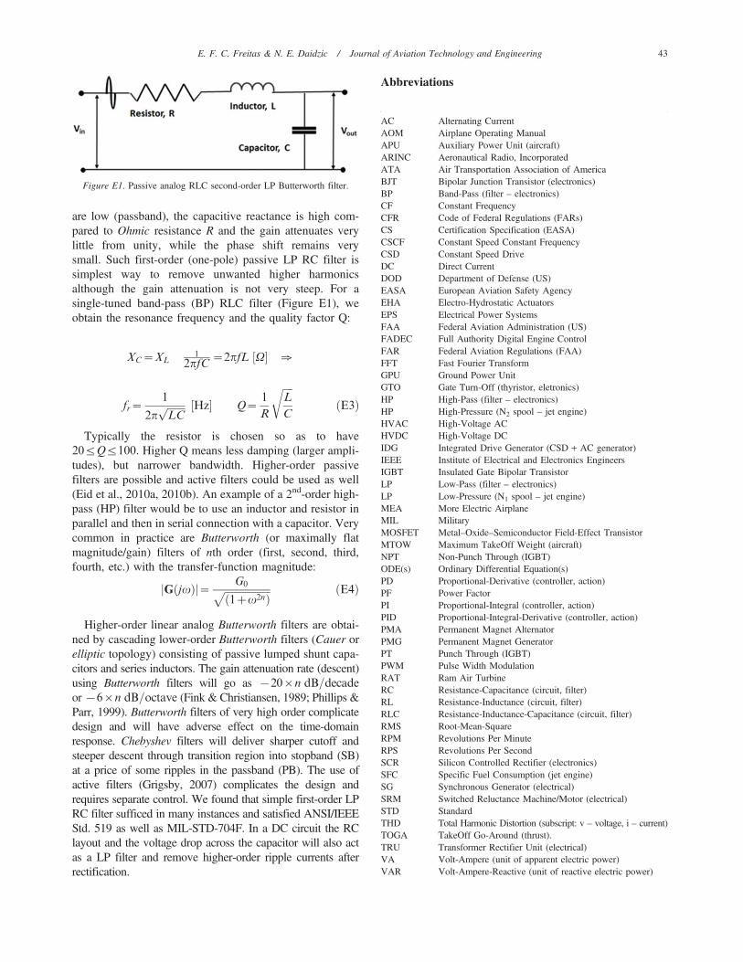
are low (passband), the capacitive reactance is high com-pared to Ohmic resistance R and the gain attenuates verylittle from unity, while the phase shift remains verysmall. Such first-order (one-pole) passive LP RC filter issimplest way to remove unwanted higher harmonicsalthough the gain attenuation is not very steep. For asingle-tuned band-pass (BP) RLC filter (Figure E1), weobtain the resonance frequency and the quality factor Q:
XC~XL1
2pfC~2pfL V½ � [
fr~1
2pffiffiffiffiffiffiffiLCp Hz½ � Q~
1
R
ffiffiffiffiL
C
rðE3Þ
Typically the resistor is chosen so as to have20ƒQƒ100. Higher Q means less damping (larger ampli-tudes), but narrower bandwidth. Higher-order passivefilters are possible and active filters could be used as well(Eid et al., 2010a, 2010b). An example of a 2nd-order high-pass (HP) filter would be to use an inductor and resistor inparallel and then in serial connection with a capacitor. Verycommon in practice are Butterworth (or maximally flatmagnitude/gain) filters of nth order (first, second, third,fourth, etc.) with the transfer-function magnitude:
G jvð Þj j~ G0ffiffiffiffiffiffiffiffiffiffiffiffiffiffiffiffiffiffi1zv2nð Þ
p ðE4Þ
Higher-order linear analog Butterworth filters are obtai-ned by cascading lower-order Butterworth filters (Cauer orelliptic topology) consisting of passive lumped shunt capa-citors and series inductors. The gain attenuation rate (descent)using Butterworth filters will go as {20|n dB=decade
or {6|n dB=octave (Fink & Christiansen, 1989; Phillips &Parr, 1999). Butterworth filters of very high order complicatedesign and will have adverse effect on the time-domainresponse. Chebyshev filters will deliver sharper cutoff andsteeper descent through transition region into stopband (SB)at a price of some ripples in the passband (PB). The use ofactive filters (Grigsby, 2007) complicates the design andrequires separate control. We found that simple first-order LPRC filter sufficed in many instances and satisfied ANSI/IEEEStd. 519 as well as MIL-STD-704F. In a DC circuit the RClayout and the voltage drop across the capacitor will also actas a LP filter and remove higher-order ripple currents afterrectification.
Abbreviations
Figure E1. Passive analog RLC second-order LP Butterworth filter.
AC Alternating CurrentAOM Airplane Operating ManualAPU Auxiliary Power Unit (aircraft)ARINC Aeronautical Radio, IncorporatedATA Air Transportation Association of AmericaBJT Bipolar Junction Transistor (electronics)BP Band-Pass (filter – electronics)CF Constant FrequencyCFR Code of Federal Regulations (FARs)CS Certification Specification (EASA)CSCF Constant Speed Constant FrequencyCSD Constant Speed DriveDC Direct CurrentDOD Department of Defense (US)EASA European Aviation Safety AgencyEHA Electro-Hydrostatic ActuatorsEPS Electrical Power SystemsFAA Federal Aviation Administration (US)FADEC Full Authority Digital Engine ControlFAR Federal Aviation Regulations (FAA)FFT Fast Fourier TransformGPU Ground Power UnitGTO Gate Turn-Off (thyristor, eletronics)HP High-Pass (filter – electronics)HP High-Pressure (N2 spool – jet engine)HVAC High-Voltage ACHVDC High-Voltage DCIDG Integrated Drive Generator (CSD + AC generator)IEEE Institute of Electrical and Electronics EngineersIGBT Insulated Gate Bipolar TransistorLP Low-Pass (filter – electronics)LP Low-Pressure (N1 spool – jet engine)MEA More Electric AirplaneMIL MilitaryMOSFET Metal–Oxide–Semiconductor Field-Effect TransistorMTOW Maximum TakeOff Weight (aircraft)NPT Non-Punch Through (IGBT)ODE(s) Ordinary Differential Equation(s)PD Proportional-Derivative (controller, action)PF Power FactorPI Proportional-Integral (controller, action)PID Proportional-Integral-Derivative (controller, action)PMA Permanent Magnet AlternatorPMG Permanent Magnet GeneratorPT Punch Through (IGBT)PWM Pulse Width ModulationRAT Ram Air TurbineRC Resistance-Capacitance (circuit, filter)RL Resistance-Inductance (circuit, filter)RLC Resistance-Inductance-Capacitance (circuit, filter)RMS Root-Mean-SquareRPM Revolutions Per MinuteRPS Revolutions Per SecondSCR Silicon Controlled Rectifier (electronics)SFC Specific Fuel Consumption (jet engine)SG Synchronous Generator (electrical)SRM Switched Reluctance Machine/Motor (electrical)STD StandardTHD Total Harmonic Distortion (subscript: v – voltage, i – current)TOGA TakeOff Go-Around (thrust).TRU Transformer Rectifier Unit (electrical)VA Volt-Ampere (unit of apparent electric power)VAR Volt-Ampere-Reactive (unit of reactive electric power)
E. F. C. Freitas & N. E. Daidzic / Journal of Aviation Technology and Engineering 43

VAC Volts ACVDC Volts DCVF Variable FrequencyVSCF Variable Speed Constant FrequencyVSI Voltage Source InverterW Watt (unit of real electric power)WF Wild Frequency
Eduardo Francis Carvalho Freitas was born in Rio de Janeiro, Brazil.He graduated with a degree in electrical engineering from ETEP–Faculdade de Tecnologia de Sao Jose dos Campos, Brazil. Currently, heis a graduate student of Mechatronics Engineering at UNITAU–Universidade de Taubate, Brazil. He was formerly a scholarship studentsponsored by the CAPES at Minnesota State University, Mankato, aspart of a sandwich degree. He spent part of 2014 and the entire year2015 as an exchange student in electrical engineering at the MinnesotaState University in Mankato, MN, while also taking aviation/aeronautics courses. His research interests include automation, powerelectronics, aircraft electrical power systems, smart grid, wind power,and renewable energy. Mr. Freitas lives just few miles from theEmbraer’s main factory in Sao Jose dos Campos.
Dr. Nihad E. Daidzic is president of AAR Aerospace Consulting, L.L.C.He is also a full professor of Aviation, adjunct professor of MechanicalEngineering, and research graduate faculty at Minnesota State University,Mankato. His Ph.D. is in fluid mechanics and Sc.D. in mechanicalengineering. He was formerly a staff scientist at the National Center forMicrogravity Research and the National Center for Space Exploration andResearch at NASA Glenn Research Center in Cleveland, OH. He has alsoheld various faculty appointments at Vanderbilt University, University ofKansas, and Kent State University. His current research interest is intheoretical, experimental, and computational fluid dynamics, micro- andnano-fluidics, aircraft stability, control, and performance, mechanics offlight, aircraft systems, and aerospace propulsion. Dr. Daidzic is ATP and‘‘Gold Seal’’ CFII/MEI/CFIG with flight experience in airplanes,helicopters, and gliders.
44 E. F. C. Freitas & N. E. Daidzic / Journal of Aviation Technology and Engineering