Embed Size (px)
DESCRIPTION
DESIGN OF CATHODIC PROTECTION
Citation preview

TECHNICAL SPECIFICATION
DESIGN OF CATHODIC PROTECTION SYSTEMS FOR ONSHORE BURIED PIPELINES
DEP 30.10.73.31-Gen.
December 1992
DESIGN AND ENGINEERING PRACTICE
USED BY
COMPANIES OF THE ROYAL DUTCH/SHELL GROUP
This document is confidential. Neither the whole nor any part of this document may be disclosed to any third party without the prior written consent of Shell Internationale Petroleum Maatschappij B.V., The Hague, the Netherlands. The copyright of this document is vested in Shell Internationale Petroleum Maatschappij B.V., The Hague, the Netherlands. All rights reserved. Neither the whole nor any part of this document may be reproduced, stored in any retrieval system or transmitted in any form or by
any means (electronic, mechanical, reprographic, recording or otherwise) without the prior written consent of the copyright owner.

DEP 30.10.73.31-Gen.December 1992
Page 2
PREFACE
DEPs (Design and Engineering Practice) publications reflect the views, at the time of publication, of:
Shell Global Solutions International B.V. (Shell GSI)
and
Shell International Exploration and Production B.V. (SIEP)
and
Shell International Chemicals B.V. (SIC)
and
other Service Companies.
They are based on the experience acquired during their involvement with the design, construction, operation and maintenance of processing units and facilities, and they are supplemented with the experience of Group Operating companies. Where appropriate they are based on, or reference is made to, international, regional, national and industry standards.
The objective is to set the recommended standard for good design and engineering practice applied by Group companies operating an oil refinery, gas handling installation, chemical plant, oil and gas production facility, or any other such facility, and thereby to achieve maximum technical and economic benefit from standardization.
The information set forth in these publications is provided to users for their consideration and decision to implement. This is of particular importance where DEPs may not cover every requirement or diversity of condition at each locality. The system of DEPs is expected to be sufficiently flexible to allow individual operating companies to adapt the information set forth in DEPs to their own environment and requirements.
When Contractors or Manufacturers/Suppliers use DEPs they shall be solely responsible for the quality of work and the attainment of the required design and engineering standards. In particular, for those requirements not specifically covered, the Principal will expect them to follow those design and engineering practices which will achieve the same level of integrity as reflected in the DEPs. If in doubt, the Contractor or Manufacturer/Supplier shall, without detracting from his own responsibility, consult the Principal or its technical advisor.
The right to use DEPs is granted by Shell GSI, SIEP or SIC, in most cases under Service Agreements primarily with companies of the Royal Dutch/Shell Group and other companies receiving technical advice and services from Shell GSI, SIEP, SIC or another Group Service Company. Consequently, three categories of users of DEPs can be distinguished:
1) Operating companies having a Service Agreement with Shell GSI, SIEP, SIC or other Service Company. The use of DEPs by these operating companies is subject in all respects to the terms and conditions of the relevant Service Agreement.
2) Other parties who are authorized to use DEPs subject to appropriate contractual arrangements (whether as part of a Service Agreement or otherwise).
3) Contractors/subcontractors and Manufacturers/Suppliers under a contract with users referred to under 1) or 2) which requires that tenders for projects, materials supplied or - generally - work performed on behalf of the said users comply with the relevant standards.
Subject to any particular terms and conditions as may be set forth in specific agreements with users, Shell GSI, SIEP and SIC disclaim any liability of whatsoever nature for any damage (including injury or death) suffered by any company or person whomsoever as a result of or in connection with the use, application or implementation of any DEP, combination of DEPs or any part thereof, even if it is wholly or partly caused by negligence on the part of Shell GSI, SIEP or other Service Company. The benefit of this disclaimer shall inure in all respects to Shell GSI, SIEP, SIC and/or any company affiliated to these companies that may issue DEPs or require the use of DEPs.
Without prejudice to any specific terms in respect of confidentiality under relevant contractual arrangements, DEPs shall not, without the prior written consent of Shell GSI and SIEP, be disclosed by users to any company or person whomsoever and the DEPs shall be used exclusively for the purpose for which they have been provided to the user. They shall be returned after use, including any copies which shall only be made by users with the express prior written consent of Shell GSI, SIEP or SIC. The copyright of DEPs vests in Shell GSI and SIEP. Users shall arrange for DEPs to be held in safe custody and Shell GSI, SIEP or SIC may at any time require information satisfactory to them in order to ascertain how users implement this requirement.
All administrative queries should be directed to the DEP Administrator in Shell GSI.
DEP 30.10.73.31-Gen.December 1992
Page 3
TABLE OF CONTENTS
1. INTRODUCTION................................................................................................51.1 SCOPE...............................................................................................................51.2 DISTRIBUTION, INTENDED USE AND REGULATORY CONSIDERATIONS. .51.3 DEFINITIONS.....................................................................................................51.4 ABBREVIATIONS..............................................................................................71.5 CROSS-REFERENCES.....................................................................................71.6 PROPRIETARY NAMES....................................................................................7
2. DESIGN REQUIREMENTS................................................................................82.1 GENERAL..........................................................................................................82.2 DESIGN INFORMATION TO BE SUBMITTED BY THE PRINCIPAL.................82.3 BASIC DESIGN..................................................................................................82.4 DETAILED DESIGN...........................................................................................82.5 PROTECTION CRITERIA..................................................................................8
3. SITE SURVEYS...............................................................................................103.1 GENERAL TERRAIN DESCRIPTION..............................................................103.2 SOIL RESISTIVITY MEASUREMENTS...........................................................103.3 SOIL INVESTIGATION.....................................................................................103.4 CURRENT DRAINAGE TESTS........................................................................103.5 STRAY CURRENTS.........................................................................................11
4. ELECTRICAL SEPARATION..........................................................................124.1 ISOLATING JOINTS.........................................................................................124.2 ISOLATING SPOOLS.......................................................................................134.3 INSULATED FLANGES....................................................................................134.4 ELECTRICAL EARTHING................................................................................13
5. ELECTRICAL CONTINUITY............................................................................15
6. COATING, DESIGN LIFE AND CURRENT DENSITY REQUIREMENTS.......166.1 PIPELINE COATING........................................................................................166.2 DESIGN LIFE...................................................................................................166.3 CURRENT DENSITY REQUIREMENTS..........................................................16
7. CHOICE OF CATHODIC PROTECTION SYSTEM..........................................18
8. IMPRESSED CURRENT SYSTEM..................................................................198.1 DC VOLTAGE SOURCES................................................................................198.2 GROUNDBEDS................................................................................................208.3 CURRENT CONTROL AND DISTRIBUTION...................................................228.4 CIVIL WORKS..................................................................................................22
9. SACRIFICIAL ANODE SYSTEM.....................................................................239.1 ZINC ANODES.................................................................................................239.2 MAGNESIUM ANODES...................................................................................239.3 CHEMICAL BACKFILL.....................................................................................249.4 CABLES AND CABLE CONNECTIONS...........................................................24
10. MONITORING FACILITIES..............................................................................2510.1 POTENTIAL MONITORING STATIONS..........................................................2510.2 FOREIGN PIPELINE BONDING FACILITIES..................................................2510.3 TEST FACILITIES AT CASINGS.....................................................................2510.4 TEST FACILITIES AT ISOLATING JOINTS / FLANGES.................................2510.5 DRAIN POINT TEST FACILITIES....................................................................2510.6 MISCELLANEOUS MONITORING FACILITIES...............................................2510.7 CABLES, TEST POSTS AND DISTRIBUTION BOXES...................................26
11. SPECIAL FACILITIES.....................................................................................2711.1 TEMPORARY PROTECTION..........................................................................2711.2 PROTECTIVE CASINGS.................................................................................2711.3 PARALLEL POWER LINES.............................................................................27

DEP 30.10.73.31-Gen.December 1992
Page 4
11.4 LIGHTNING PROTECTION.............................................................................2711.5 SURGE ARRESTORS.....................................................................................2811.6 MONITORING EQUIPMENT............................................................................28
12. CABLES AND CABLE ACCESSORIES..........................................................2912.1 CABLES...........................................................................................................2912.2 ANODE CABLE CONNECTIONS....................................................................2912.3 CONNECTION OF CABLES TO THE PIPELINE.............................................2912.4 TEST POSTS AND DISTRIBUTION BOXES...................................................30
13. DOCUMENTATION..........................................................................................3213.1 DESIGN DOCUMENTS....................................................................................3213.2 MATERIAL SCHEDULES.................................................................................3213.3 INSTALLATION PROCEDURES......................................................................3313.4 COMMISSIONING PROCEDURES.................................................................3313.5 OPERATING AND MAINTENANCE MANUAL.................................................33
14. SAFETY...........................................................................................................34
15. REFERENCES.................................................................................................35
APPENDICES
APPENDIX 1 SPECIMEN COPY OF REQUISITION SHEET.......................................36

DEP 30.10.73.31-Gen.December 1992
Page 5
1. INTRODUCTION
1.1 SCOPE
This DEP specifies the minimum requirements for the design of cathodic protection systems for onshore buried pipelines.
This DEP is also applicable to short "offshore" pipelines or pipeline sections (e.g. loading lines) to be protected by onshore based cathodic protection installations.
This DEP is not intended to be used for the design of cathodic protection systems for on-plot buried piping.
This DEP replaces and supersedes an earlier publication under the same number dated June 1983.
1.2 DISTRIBUTION, INTENDED USE AND REGULATORY CONSIDERATIONS
Unless otherwise authorized by SIPM, the distribution of this document is confined to companies forming part of the Royal Dutch/Shell Group or managed by a Group company, and to Contractors nominated by them (i.e. the distribution code is "C" as defined in DEP 00.00.05.05-Gen.).
This DEP is intended to be used for new pipeline construction projects as well as for retrofitting of cathodic protection on existing pipelines in relation to exploration and production facilities, oil refineries, chemical plants, gas plants and supply/marketing installations.
If national and/or local regulations exist in which some of the requirements may be more stringent than in this DEP the Contractor shall determine by careful scrutiny which of the requirements are the more stringent and which combination of requirements will be acceptable as regards safety, environmental, economic and legal aspects. In all cases the Contractor shall inform the Principal of any deviation from the requirements of this DEP which is considered to be necessary in order to comply with national and/or local regulations. The Principal may then negotiate with the Authorities concerned with the object of obtaining agreement to follow this DEP as closely as possible.
1.3 DEFINITIONS
1.3.1 General definitions
The Contractor is the party which carries out all or part of the design, engineering, procurement, installation, and commissioning or management of a project or operation of a facility. The Principal may sometimes undertake all or part of the duties of the Contractor.
The Manufacturer/Supplier is the party which manufactures or supplies equipment and services to perform the duties specified by the Contractor.
The Principal is the party which initiates the project and ultimately pays for its design and construction. The Principal will generally specify the technical requirements. The Principal may also include an agent or consultant, authorized to act for the Principal.
The word Shall indicates a requirement.
The word Should indicates a recommendation.
1.3.2 Specific Definitions
cathodic protection - the process to reduce or prevent corrosion of metal structures in contact with an electrolyte by the flow of direct current from the electrolyte into the structure surface.
cathodic protection station - a combination of equipment installed to provide cathodic protection to the pipeline.
DEP 30.10.73.31-Gen.December 1992
Page 6
coating breakdown factor - the ratio between the surface area of exposed metal due to coating breakdown and the total surface area under consideration. The factor is used to determine the average current density on coated metal from current densities related to bare steel.
current density - the amount of current per unit area of the steel surface, coated or uncoated, in contact with the electrolyte.
drain point - the point on the pipeline where the connection of the negative terminal of the cathodic protection voltage source is made to conduct (drain) the returning current from the pipeline to the voltage source.
electrolyte - a conductive liquid or material such as soil or water in which an electric current can flow.
foreign structures/pipelines - metal structures, or pipelines other than the pipeline under consideration, in contact with the same electrolyte as the pipeline, and which are or may become under the influence of the pipeline's cathodic protection system.Foreign structures/pipelines may be owned by the Principal or other companies and may or may not be equipped with cathodic protection.
groundbed - the system of buried or submerged electrodes, to conduct the required current into and through the electrolyte to the steel surface to be protected.
midpoint - the point on a pipeline between two cathodic protection stations where the influence of the two cathodic protection stations is expected to be equal and the protection levels are usually lowest.
natural potential - the pipe to soil potential measured when no cathodic protection is applied and polarization caused by cathodic protection is absent.
"OFF" potential - the pipe to soil potential measured immediately after the cathodic protection system is switched off and the applied electrical current stops flowing to the pipeline surface, but before polarization of the pipeline has decreased.
"ON" potential - the pipe to soil potential measured while the cathodic protection system is continuously operating.
pipeline - the pipeline or pipelines with associated equipment as defined in the scope of the cathodic protection design contract.
pipe to soil potential - the difference in electrochemical potential between a pipeline or foreign structure/pipeline and a specified reference electrode in contact with the electrolyte. Similar terms such as structure to soil potential, pipe to electrolyte potential, pipe to (sea)water potential are sometimes used as applicable in the particular context.
polarization - the change of the pipe to soil potential caused by the flow of DC current between an electrolyte and a steel surface.
polarization cell (Kirkcell) - a device inserted in the earth connection of a structure that isolates for DC in the cathodic protection voltage range.
reference electrode - an electrode of which the electrochemical potential is accurately reproducible and which serves as a reference for pipe to soil potential measurements.
requisition - the data/requisition sheet(s) DEP 30.10.73.93-Gen., to be used by the Principal and completed by the Contractor. A specimen copy for information is included in Appendix 1. The actual forms can be found in the requisitioning binder (DEP 30.10.01.10-Gen.).
stray currents - electrical currents running through the electrolyte, originating from a foreign DC source, causing interaction with the corrosion and cathodic protection processes of the pipeline. Stray currents may also originate from the pipeline's cathodic protection system and act upon foreign structures/pipelines.
DEP 30.10.73.31-Gen.December 1992
Page 7
1.4 ABBREVIATIONS
Ag/AgCl Silver/Silver Chloride as used for the Silver/Silver Chloride type of reference electrode.
Cu/CuSO4 Copper/Copper Sulphate as used for the Copper/Copper Sulphate type of reference electrode.
AC Alternating Current
DC Direct Current
GRE Glass reinforced epoxy
1.5 CROSS-REFERENCES
Where cross-references to other parts of this DEP are made, the referenced section is shown in brackets. Other documents referenced by this DEP are listed in (15).
1.6 PROPRIETARY NAMES
The names "Wenner", "Shepard", "Kirkcell" and "Swain" are used in this specification to indicate measuring techniques or equipment types, commonly understood by those names in cathodic protection engineering. It is not intended to indicate a requirement to apply equipment of that particular brand name.

DEP 30.10.73.31-Gen.December 1992
Page 8
2. DESIGN REQUIREMENTS
2.1 GENERAL
The design of cathodic protection systems shall be carried out by a professional and experienced cathodic protection engineering Contractor approved by the Principal.
For new construction projects, the design of the cathodic protection system shall be an integral part of the total pipeline design. Pipeline isolation and a suitable pipeline coating system shall be provided for in the pipeline design.
To achieve an effective cathodic protection design for a pipeline system, a site survey shall be performed to collect essential information on soil resistivity, geographical factors, the likelihood or the existence of stray currents and any other important features along the pipeline route.
When designing a cathodic protection system for retrofitting to an existing pipeline certain repairs and modifications to the pipeline may be necessary to comply with these specifications. Other requirements may have to be determined by site investigations.
The cathodic protection system shall be designed so that any external corrosion on the pipeline is eliminated and any adverse stray current effects on the pipeline or on foreign structures/pipelines is avoided.
2.2 DESIGN INFORMATION TO BE SUBMITTED BY THE PRINCIPAL
By means of the requisition, the Principal shall submit to the Contractor all technical information required to carry out the cathodic protection design.
This information shall include at least:
- detailed information on the pipeline to be protected (length, diameter, coating, scope limits, etc.)
- the required design life of the cathodic protection system. This design life is normally equal to the design life of the pipeline (6.2)
- requirements on cathodic protection systems and/or materials (7)- relevant drawings (pipeline route, existing systems, foreign structures/pipelines)- applicable environmental and operating conditions for the cathodic protection
equipment.
2.3 BASIC DESIGN
The Contractor shall submit to the Principal a basic cathodic protection design for review and approval which shall include the documentation listed in (13.1). Only after such approval shall the Contractor commence detailed design (2.4).
In some cases (e.g. on small projects or standard projects) the Principal may request the Contractor to carry out both basic design and detailed design in one operation. If so required, this shall be entered on the requisition.
2.4 DETAILED DESIGN
The detailed design shall contain all information required for the procurement of cathodic protection equipment and for the construction, commissioning, and hand over of the cathodic protection system. The detailed design package shall contain the documentation listed in 13.1.
2.5 PROTECTION CRITERIA
In this specification the pipe-to-soil potential is used as a criterion for effective cathodic protection.

DEP 30.10.73.31-Gen.December 1992
Page 9
For pipelines to be considered fully cathodically protected, the "OFF" potential on all parts of the pipeline shall be equal to or more negative than the protection potential value stated in Table I.
To avoid detrimental effects on the applied coating or on the pipeline due to overprotection, "OFF" potentials for carbon steel shall not be more negative than the overprotection limit value as stated in Table I.
The cathodic protection criteria for corrosion resistant steels and some high strength steels depend on the susceptibility of the material to hydrogen induced stress cracking. The protection criteria for pipelines made of such materials shall be determined from case to case. This is also applicable when designing a cathodic protection system for a pipeline crossing or approaching another pipeline made of such a material. The Principal shall indicate on the requisition if this requirement applies.
The protection potential for anaerobic environments is applicable when soil investigations have confirmed the presence of active sulphate reducing bacteria in anaerobic soil (3.3).
Table I Potential limits for cathodic protection of pipelines
"OFF" POTENTIALS, mVREFERENCE ELECTRODE :
Cu/CuSO4 Ag/AgCl/seawater
Zinc
Protection potential for steel in aerobic environment
-850 -800 +250
Protection potential for steel in anaerobic environment
-950 -900 +150
Overprotection limit for carbon steel
-1150 -1100 -50
NOTE: Cu/CuSO4 reference is used for pipelines in soil,
Ag/AgCl/seawater reference is used in seawater.Zinc reference is used in both soil and seawater for special monitoring purposes only.

DEP 30.10.73.31-Gen.December 1992
Page 10
3. SITE SURVEYS
Before the design of a cathodic protection for a pipeline is made a pre-design site survey shall be carried out.
Information obtained during previous surveys for the proposed pipeline route may be used provided that the date, conditions and source of such surveys are included in the survey report.
If the area to be surveyed is affected by seasonal changes, these shall be taken into account. If possible a survey shall be carried out during different seasonal conditions and the most severe conditions shall be used for the design.
The following items are an essential part of such a survey:
3.1 GENERAL TERRAIN DESCRIPTION
The survey shall include general information of the terrain along the pipeline route including:
- type of terrain and vegetation (urban areas, industrial areas, farm land, forests, open fields, desert, swamps, rocks)
- visible relevant features and crossings (rivers, canals, railways, main roads, overhead power lines, other pipelines)
- all other information that is considered relevant to the design of a cathodic protection system.
3.2 SOIL RESISTIVITY MEASUREMENTS
Soil resistivity measurements shall be carried out along the route of the pipeline at pipeline depth. The number of measurements should be determined locally but measurements should at least be carried out when there are visual changes in soil characteristics.
For each type of soil, readings should be taken in at least two different locations. At each location a minimum of 2 measurements shall be carried out.
Acceptable methods for soil resistivity measurements are:
- four terminal resistivity method (Wenner)- two terminal resistivity method (Shepard)- soil sample (soil box) resistivity method
When the soil resistivity measurements are used to locate suitable places for surface groundbeds, the four terminal method shall be used to determine the resistivity at greater depths (10 m maximum).
Other soil resistivity measuring methods require approval by the Principal.
3.3 SOIL INVESTIGATION
If it may be assumed that corrosive conditions are present due to bacterial activity, further chemical and bacterial soil analysis shall be carried out. For test methods, refer to BS 1377 parts 3 and 9. This requirement is also applicable for imported backfill used for pipeline construction.
3.4 CURRENT DRAINAGE TESTS
When designing a cathodic protection system for existing pipelines a current drainage test should be performed to determine the current requirement and optimal current distribution. This may necessitate temporary installation of one or more groundbeds and DC power sources (e.g. batteries or portable rectifiers), timer-units, and test facilities to the pipeline under investigation.

DEP 30.10.73.31-Gen.December 1992
Page 11
To obtain relevant results, pipeline isolation equipment (4) and monitoring facilities (10) should be installed before current drainage tests are carried out.
The required current is determined when, after full polarization is achieved, the "OFF" potentials measured at regular points along the pipeline (10.1) are within the protection criteria as given in Table I (2.5). This current demand shall further be adjusted to allow for expected further deterioration of the coating during the remaining life of the pipeline.
If the pipeline has been previously cathodically protected, historical data may be used to determine the current demand.
3.5 STRAY CURRENTS
The Contractor shall investigate possible sources of detrimental DC stray currents and include proposals in the design on how to mitigate the effect of such stray currents.
If the effect of stray currents cannot be predicted, the Contractor shall carry out a stray current survey at the time of commissioning.
Stray currents shall be eliminated at the source by suitable insulation or other means. If this is impossible other measures such as installation of a current drainage system shall be designed.

DEP 30.10.73.31-Gen.December 1992
Page 12
4. ELECTRICAL SEPARATION
Pipelines shall be electrically isolated from other plant, foreign structures/pipelines and electrical and instrument earthing systems.
Monoblock isolating joints (4.1) shall be used where possible.
Isolating joints, flanges or spools should be installed:
- At both extremities of a buried section of pipeline;- At branch lines;- Between pipeline sections with different external coating systems (6.1);- Between pipeline sections running in different types of electrolyte (e.g. river crossings);- In areas of high telluric activity.
Short branch line, small pipeline facilities and/or crossings of small rivers do not always need to be isolated and can sometimes be incorporated in the main pipeline cathodic protection system. If isolation is omitted, the Contractor shall justify this choice in his basic design.
Isolating joints/flanges shall never be buried. They shall be installed above ground or in inspection pits.
Parallel pipelines shall be electrically isolated from each other except if running in the same trench and having the same coating system.
Common, metal, pipe supports should be avoided or electrically isolated from the pipelines.
Each isolating joint/flange shall be provided with test facilities (10.4).
If the pipeline isolation is to be designed by others, the Contractor shall ensure that the arrangement will be adequate to allow effective cathodic protection.
For existing pipelines the Contractor shall investigate the quality of the existing pipeline isolation and submit with his basic design any requirements for improvements to obtain suitable isolation.
Safety or instrument earthing shall be compatible with the cathodic protection system.
In areas where there is any risk of the presence of high voltages on the pipeline, e.g. caused by nearby power systems (11.3) or lightning (11.4), the isolating joints or flanges shall be protected using earthing (4.4) or surge arrestors (11.5).
Isolating joints and flanges should be painted in a contrasting colour for easy identification. The colour should be consistent in one area. The paint shall be compatible with the pipeline coating. Red paint or black coal tar epoxy are commonly used. Paints containing metallic pigments (such as zinc or aluminium) shall not be used for isolating joints/flanges.
4.1 ISOLATING JOINTS
The design, materials, dimensions and construction of the isolating joints shall meet the design requirements of the pipeline.
Isolating joints shall be internally coated by the manufacturer over their full length using an amine cured epoxy coating, applied on a blast cleaned surface (Sa 2½ , ISO 8501-1). A length of 50 mm at each end shall be left uncoated to allow welding.
All sealing and isolation materials shall be resistant to the product transported.
The isolating joints shall withstand a voltage of 1500 volt AC, 50 Hz, across the joint for 5 minutes without bridging or reduction in electrical resistance.
The electrical resistance across the joint shall be more than 1 mega Ohm (106 Ohm) measured at 1000 V DC in dry air.
If the product transported by the pipeline is dry gas, dry crude oil, or oil products, the overall length of the isolating joint shall be at least one metre.

DEP 30.10.73.31-Gen.December 1992
Page 13
If the product transported by the pipeline is an electrolyte, or it may be anticipated that it may contain an electrolyte at any time during the life of the pipeline, the following rule applies:
If the resistivity of the electrolyte is higher than 100 ohm.cm, or the volume occupied by the electrolyte is less than 5% of the pipeline volume, the overall length of the isolating joint shall be four times the pipe diameter (with a minimum of one metre).
If the resistivity of the electrolyte is below 100 ohm.cm and the volume of electrolyte is more than 5% of the pipeline volume, isolating spools shall be used.
The resistance across isolating joints shall be measured immediately before welding into the pipeline. The minimum resistance shall be 1 mega ohm (106 ohm).
4.2 ISOLATING SPOOLS
Isolating spools shall be used if required by the rules above (4.1).
The length of an isolating spool shall be determined by the following formula:
L = (400 / ) x D
where:
L = length of spool (cm), = electrolyte resistivity (Ohm.cm),D = nominal pipe diameter (cm).
Isolating spools may be manufactured out of non-conductive composite pipe material (GRE) or as an internally coated or lined steel spool with isolating joints or flanges at both ends, depending on pipeline service, pressure and temperature.
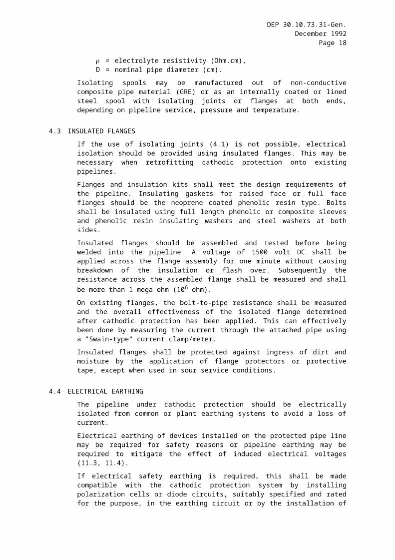
4.3 INSULATED FLANGES
If the use of isolating joints (4.1) is not possible, electrical isolation should be provided using insulated flanges. This may be necessary when retrofitting cathodic protection onto existing pipelines.
Flanges and insulation kits shall meet the design requirements of the pipeline. Insulating gaskets for raised face or full face flanges should be the neoprene coated phenolic resin type. Bolts shall be insulated using full length phenolic or composite sleeves and phenolic resin insulating washers and steel washers at both sides.
Insulated flanges should be assembled and tested before being welded into the pipeline. A voltage of 1500 volt DC shall be applied across the flange assembly for one minute without causing breakdown of the insulation or flash over. Subsequently the resistance across the assembled flange shall be measured and shall be more than 1 mega ohm (106 ohm).
On existing flanges, the bolt-to-pipe resistance shall be measured and the overall effectiveness of the isolated flange determined after cathodic protection has been applied. This can effectively been done by measuring the current through the attached pipe using a "Swain-type" current clamp/meter.
Insulated flanges shall be protected against ingress of dirt and moisture by the application of flange protectors or protective tape, except when used in sour service conditions.
4.4 ELECTRICAL EARTHING
The pipeline under cathodic protection should be electrically isolated from common or plant earthing systems to avoid a loss of current.
Electrical earthing of devices installed on the protected pipe line may be required for safety reasons or pipeline earthing may be required to mitigate the effect of induced electrical voltages (11.3, 11.4).

DEP 30.10.73.31-Gen.December 1992
Page 14
If electrical safety earthing is required, this shall be made compatible with the cathodic protection system by installing polarization cells or diode circuits, suitably specified and rated for the purpose, in the earthing circuit or by the installation of separate earthing electrodes, made of zinc or galvanized steel, buried in low resistivity (9.3) backfill and not in direct electrical continuity with other earthing systems.
If pipeline earthing is to be installed to mitigate the effect of AC induced voltages on the pipeline (11.3) this should be done at the locations where the anticipated or measured voltages to ground are highest and where the pipeline is exposed and can be touched by personnel.

DEP 30.10.73.31-Gen.December 1992
Page 15
5. ELECTRICAL CONTINUITY
Isolation joints installed at coating/electrolyte changes (4) shall always be bonded in test posts (10.4), to keep the pipeline electrically continuous when the cathodic protection is operational.
If cathodic protection is to be applied on non-welded pipelines the continuity of the pipeline shall be ensured. This should be done by the installation of permanent bonds over high resistance flanges/couplings, using cables and approved attachment methods (12).
The continuity of non-welded pipelines shall be checked, e.g. by carrying out overlapping potential measurements.

DEP 30.10.73.31-Gen.December 1992
Page 16
6. COATING, DESIGN LIFE AND CURRENT DENSITY REQUIREMENTS
6.1 PIPELINE COATING
By means of the requisition, the Principal shall inform the Contractor of the existing or planned coating system.
If adjacent structures have different coating types or coatings of significant difference in coating condition, the appropriate design parameters for each coating type shall be used in the design. If interference is expected pipeline isolation (4) shall be provided for.
6.2 DESIGN LIFE
The cathodic protection system shall be designed for the design life of the pipeline unless otherwise required by the Principal.
If the normal life of components of the cathodic protection system is less than the design life of the pipeline or if adequate control of the cathodic protection levels at the beginning and at the end of the design life are technically incompatible, the Contractor shall include and justify in his basic design the installation of a system based on this shorter life and shall include methods and instructions for future upgrading of the system.
This may be the case with sacrificial anode systems (9) and with battery operated cathodic protection systems or solar generators (8.2.3).
6.3 CURRENT DENSITY REQUIREMENTS
The Contractor shall carry out pipeline attenuation calculations to determine the pipeline current demand and spacing between cathodic protection stations as required during the pipeline design life. The current densities in Table II shall be used as minimum design values for new construction projects.
The current density values in Table II are to be related to the total pipeline surface area and take into account coating deterioration during the referred life of the pipeline.
It is assumed that pipeline construction is carried out in a manner to avoid coating damage during construction and operation.
To determine the current requirement for existing pipelines, where the actual condition of the applied coating is unknown, a current drainage test shall be carried out (3.4). The cathodic protection system capacity shall be determined as the highest of the two values determined by the current drainage survey and above calculations.
For the protection of pipelines with elevated operating temperatures the minimum design current densities given in Table II shall be increased by 25% per 10 °C rise in temperature above 30 °C.

DEP 30.10.73.31-Gen.December 1992
Page 17
Table II Design current densities for different pipeline coatings(operating temperature up to 30 °C)
PIPELINE LIFE (years)0-5 5-15 15-30
COATING TYPE CURRENT DENSITY (mA/m2)Asphalt bitumen, 6 mmButyl rubber tapeAsphalt mastic
0.040 0.100 0.200
Fusion bonded epoxyLiquid epoxyCoal tar epoxy
0.010 0.020 0.05
PolyethylenePolypropylene
0.002 0.005 0.010
NOTE: The current densities given in Table II already include the current requirements due to the expected coating breakdown during the pipeline life.
DEP 30.10.73.31-Gen.December 1992
Page 18
7. CHOICE OF CATHODIC PROTECTION SYSTEM
For the cathodic protection of land based buried pipelines an impressed current system is preferred.
The type of cathodic protection system to be applied (i.e. sacrificial anodes or impressed current) shall be as indicated on the requisition. If not specified, the Contractor shall select the type of cathodic protection and shall justify his choice in his basic design.
The following factors should be considered when making the selection.
- soil resistivity- total current demand- economic considerations- presence of stray currents- availability of power supply- site layout- presence of other conductors- maintenance- possibility to use existing, Principal owned cathodic protection systems.
If the above factors do not clearly justify one particular system, impressed current shall be used.
If the pipeline under protection may be influenced by stray currents, impressed current shall be applied.

DEP 30.10.73.31-Gen.December 1992
Page 19
8. IMPRESSED CURRENT SYSTEM
8.1 DC VOLTAGE SOURCES
The preferred DC voltage source is a transformer/rectifier unit, fed by an AC power supply.
Alternative voltage sources are described briefly in this section, but they are usually more expensive, both in installation and maintenance costs.
The DC voltage source shall be as indicated on the requisition. If not specified, the Contractor shall justify his own choice in the basic design if he proposes one of the alternative DC sources. The justification shall be based on local geographical circumstances and infrastructure.
The maximum DC output voltage of a DC power source shall be 50 volts.
8.1.1 Transformer/rectifiers
Transformer/rectifiers shall comply with IEC 146.
Transformer/rectifiers shall be of a special design for cathodic protection service and should be 3 phase units if available.
Transformer/rectifiers shall be suitable to operate under the prevailing service conditions.
The output voltage shall be adjustable from zero to the maximum rated output when on load. A stepless (continuous) adjustment is preferred. If tapping switches are proposed, these shall be front mounted switches with a step-size of maximum 3% of maximum output. Transformer tapping using relocation of jumpers shall not be used.
Electronic voltage and/or current control may be used, if required in combination with automatic potential control (8.3.2).
Transformer/rectifiers shall not be installed in series or in parallel in the same cathodic protection circuit.
The rectifier shall be constructed using high current density selenium cells or silicon diodes so arranged as to provide full wave rectification. The current rating of the diodes shall be more than 1.25 times the maximum current rating of the rectifier and have a minimum peak inverse voltage of 1200 V.
The output rms ripple current shall not exceed 5% of the DC output current between 5% and 100% of the rated current output.
The transformer/rectifier shall be provided with an isolator or Moulded Case Circuit Breaker (MCCB) on its incoming circuit and, where applicable, on its AC sub-circuits. Additionally, suitably sized fuses (type gG to IEC 269) shall be installed on the transformer/rectifier's phase AC sub-circuits and negative DC output circuits.
The transformer/rectifier shall be capable of withstanding a short circuit of up to 15 seconds duration at the output terminals without damage to any of its devices.
The transformer/rectifier shall be provided with approximately 70 mm diameter meters or similarly sized square pattern meters to read the output voltage and current. The measuring accuracy shall be better than 2% of full scale.
The polarity of the DC terminals and AC supply terminals shall be clearly marked. AC and DC cables shall be physically separated by an insulating panel.
Unless otherwise stated, a built-in timer unit is required. The timer unit may be mechanical or electronic and shall be capable of switching the full output current in a sequence of 50 seconds on and 10 seconds off. If a pipeline system is cathodically protected by more than one transformer/rectifier, all transformer/rectifier timer units should be provided with a facility for synchronous switching. During normal operation the timer shall be bypassed.
If a transformer/rectifier is oil cooled, the incoming cables shall terminate in separate non oil filled cable boxes and penetration into the tank shall be via bushings above oil level. A sight glass and thermometer shall be provided.

DEP 30.10.73.31-Gen.December 1992
Page 20
Transformer/rectifiers should be installed in a non-hazardous area. If this is not possible, the construction of the rectifier units shall fulfill the requirements of the hazardous area classification applicable for the site. The Contractor shall obtain the required information on area classification from the Principal.
If installed outdoors, the enclosure shall have a minimum degree of protection IP 54 in accordance with IEC 529.
8.1.2 Engine generator sets
Where AC power is not available to supply rectifiers and the required power is high, engine generator sets may be used to provide the electrical supply needed.
If a remote survey unit with alarms cannot be installed, a two generator system shall be used (one running, one on standby) with an automatic change-over system.
8.1.3 Batteries, solar and wind generators
If the AC mains suffers frequent power failures, the use of batteries, charged by mains powered battery chargers may be used instead of transformer/rectifiers.
Battery charging may also be achieved by a wind-powered generator or by solar cells.
The batteries should be charged on a regular basis to provide a continuous source of cathodic protection current.
Cathodic protection systems using batteries shall be provided with suitable output voltage and/or current control equipment and a load cut off system to avoid damage to the batteries due to a complete discharge.
Battery chargers and generators shall be provided with regulators to ensure that the recommended charging rates are applied and shall be equipped with a protection system to prevent overcharging of the batteries.
The design of wind and solar generators shall be based on extensive local weather reports, stating average and minimum sun and/or wind periods and intensity during all seasons, generally a one year period, to determine the capacity of the system.
Wind and solar generators shall be rated to recharge the batteries in less than 48 hours from a partially discharged state due to extended period of no wind/sun.
In tropical areas the generators and batteries shall be designed to operate in the high ambient temperatures. Solar generators should be designed to maintain the design capacity at the highest ambient temperature.
8.1.4 Thermoelectric generators
The use of thermoelectric generators may be considered. The Contractor shall justify this selection and obtain approval from the Principal for their use.
8.2 GROUNDBEDS
The groundbed of an impressed current cathodic protection system shall be designed such that:
- its mass and quality is sufficient to last for the design life of the system- its resistance to earth allows the maximum predicted current demand to be met at 80%
or less of the voltage capacity of the DC source during the design life of the system- its location is remote from the pipeline and any other buried structure, to provide a
regular distribution of current along the pipeline- the risk of causing harmful interference on other buried structures is minimized.
The selection of the location and the type of groundbed shall depend on local conditions such as:
- Soil conditions and resistivity at various depths

DEP 30.10.73.31-Gen.December 1992
Page 21
- Groundwater levels and resistivity- Strong seasonal changes in surface soil conditions- Available terrain (for surface groundbeds)- Risk of shielding (specially for parallel pipelines)- Risk of damage by excavation (surface groundbeds).
8.2.1 Deepwell groundbeds
Deepwell groundbeds should be used:
- if the soil conditions at the required depth are suitable to meet the requirements in (8.2).- if there is a risk of shielding by other pipelines or buried structures- if the available space is limited- if there is a risk of stray currents on adjacent installations.
The Contractor shall include in his basic design a calculation of the groundbed resistance based on the most accurate soil resistivity data available, using established methods and formulae.
The Contractor shall specify in his detailed design the method of drilling the deepwell, establishing the resistivity of the soil at depth, completion of the borehole and the method of installation of the anodes and backfill.
The borehole design and construction shall be such that undesirable transfer between water bearing formations and pollution of underlying strata from the surface (e.g. tank farms) is prevented.
Metal casings may be used at the surface for stabilizing the borehole and in the active section of the groundbed. Casing at depth shall be electrically isolated from metal casing and structures at the surface. To achieve such isolation plastic casing can be used.
Deepwell groundbeds shall be provided with adequate venting pipes to prevent gas blocking of the well. Vent pipe material shall be chlorine resistant. Filter gravel shall be used to avoid blockage of the vent pipe by coke backfill.
8.2.2 Surface groundbeds
Shallow surface groundbeds should be used:
- if the soil conditions at the proposed groundbed depth, are suitable to meet the requirements in (8.2).
- if sufficient distance from the pipeline can be achieved and there is no risk of shielding.
In a shallow groundbed, the anodes may be installed horizontally or vertically. The choice depends on the soil resistivity distribution at various depths.The anodes or the highest point of the carbonaceous backfill shall be not less than 1 metre below ground level.
The design shall include a calculation of the groundbed resistance based on the most accurate soil resistivity data available, using established methods and formulae.
The Contractor shall include in his detailed design the method of construction of the groundbed and the method of installation of the anodes and backfill.
8.2.3 Impressed current anodes and backfill
Anode material shall be selected from:- graphite- high silicon iron /chromium alloy- magnetite- metal oxide plated metal- platinised titanium/niobium.
The Contractor shall demonstrate that the anode weight and dimensions and the selected anode material are suitable to supply the required anode current output, to cover the design life of the cathodic protection system and are compatible with the soil composition.

DEP 30.10.73.31-Gen.December 1992
Page 22
A carbonaceous backfill or other low resistivity backfill material shall be used, unless the ground conditions dictate otherwise.
Individual anode circuits shall be provided with shunts to measure anode current outputs.
8.3 CURRENT CONTROL AND DISTRIBUTION
8.3.1 Current control
Each pipeline shall be provided with an individual negative connection.
Variable resistors shall be installed in the negative drain circuit, if required, to balance the current to each of the adjacent pipelines. Each negative circuit shall be provided with a suitably sized shunt and diode at the DC source. The installation of the diode is required to prevent mutual influence of pipelines during "ON-OFF" surveys.
A distribution box for all cables, diodes and current measurement facilities shall be installed (12).
8.3.2 Automatic potential control
If specified on the requisition, the DC voltage source shall be provided with automatic potential control. To achieve this a suitable permanent reference electrode shall be buried close to the pipeline (11.6).
The potential measuring circuit shall have a minimum input resistance of 100 mega ohms. The control system shall have an accuracy of 10 millivolts and shall be provided with adjustable voltage and current limiting circuits and/or alarms to protect the pipeline against overprotection in case of failure of a reference cell. A panel mounted meter to read the pipe-to-soil potential shall be provided.
8.3.3 Cables
All cables, cable connections and cable accessories shall be in accordance with (12).
8.4 CIVIL WORKS
The Contractor shall specify in the detailed design the civil works required to install the cathodic protection system. Such works include transformer/rectifier plinths, deepwell head works, mounting details of distribution boxes and test posts, cable trenches, security fencing etc.

DEP 30.10.73.31-Gen.December 1992
Page 23
9. SACRIFICIAL ANODE SYSTEM
The use of a sacrificial anode system may be considered:
- if the pipeline (section) runs in low resistivity soil, water, swamps or marshes (9.1, 9.2)- on short pipeline sections, for economic reasons- if no power for impressed current is available- for temporary protection on newly laid pipelines (11.1)- for temporary protection of existing pipelines, if pipeline isolation cannot be immediately
installed- if it can be assumed that maintenance of electrical equipment associated with an
impressed current system cannot be carried out by the operator- for localised (hot-spot) protection to supplement impressed current systems
If cathodic protection by sacrificial anodes is selected, the Contractor shall show by measurement and calculation that:
- the resistivity of the soil is sufficiently low to allow successful application of sacrificial anodes
- the selected type of anode is capable of continuously supplying the maximum current demand
- the total mass of anode material is sufficient to supply the required current during the design life of the system.
The anodes should be buried in low resistivity chemical backfill (9.3) to obtain the required output.
The Manufacturer/Supplier of sacrificial anodes shall supply anodes which are clearly marked with the type of material (trade name), anode weight (without backfill), and charge number. The supplier shall provide full documentation of number, types, weight, dimensions, chemical analysis and performance data of the anodes.
At the manufacturer/supplier's works the anodes shall be inspected for mechanical damage, casting quality and the bonding of the anode core/cable.
9.1 ZINC ANODES
Zinc anodes should not be used if the resistivity of the electrolyte is greater than 1500 ohm.cm.
Zinc anode composition for standard applications shall be in accordance with Table III.
Table III Chemical composition for Zinc Anodes
Cu 0.005 max. %Al 0.10 - 0.50 %Si 0.125 max. %Fe 0.005 max. %Cd 0.025 - 0.07 %Pb 0.006 max. %Zn remainder
For non-standard applications (e.g. high temperature) special alloys may be used which shall be approved by the Principal.
9.2 MAGNESIUM ANODES
Magnesium should not be used if the resistivity of the electrolyte is higher than 3000 ohm.cm.
The use of chemical backfill around buried anodes shall be used to increase current output and to avoid passivity.
DEP 30.10.73.31-Gen.December 1992
Page 24
Magnesium anode composition for standard applications shall be in accordance with Table IV.
Table IV Chemical composition of magnesium anodes
Cu 0.02 max. %Al 5.3 - 6.7 %Si 0.1 max. %Fe 0.003 max. %Mn 0.15 min. %Ni 0.002 max. %Zn 2.5 - 3.5 %Mg remainder
For special applications (e.g. high output in high resistivity soil) special alloys may be used, which shall be approved by the Principal.
9.3 CHEMICAL BACKFILL
Backfill for sacrificial anodes shall consist of a mixture of Gypsum, Bentonite clay and sodium sulphate. The ratio of the components shall be such to obtain optimum results in the prevailing resistivity and soil wetness.
The supplier shall include the composition of the backfill material in the anode documentation.
9.4 CABLES AND CABLE CONNECTIONS
All cables, cable connections and cable accessories shall be in accordance with (12).
Sacrificial anode cables shall be connected to the pipeline via a bondbox and shunts to allow anode current monitoring.
For magnesium anodes it is allowed to install a resistor in the anode circuit to limit the protection levels to within the protection criteria (2.5).

DEP 30.10.73.31-Gen.December 1992
Page 25
10. MONITORING FACILITIES
The contractor shall include in his design sufficient monitoring facilities to ensure effective survey of the level of the cathodic protection along the pipeline. The minimum requirements for monitoring facilities are given below.
10.1 POTENTIAL MONITORING STATIONS
To monitor pipe to soil potentials, test posts shall be installed at distances of maximum 1000 m along the pipeline. In urban or industrial areas a closer distance (maximum 200 m) should be taken. At least one test post shall be installed between major obstacles such as waterways, main roads and railways to allow unobstructed close interval potential surveys.
Two separate cables shall be attached to the pipeline and terminated in the test post.
If pipelines are running in parallel, but not in the same trench, each pipeline shall be provided with separate potential monitoring facilities. Test posts should be installed not more than 2.5 m away from the pipeline.
10.2 FOREIGN PIPELINE BONDING FACILITIES
At crossings with foreign pipelines, a bonding facility shall be provided, consisting of two separate cables attached to each individual pipeline, terminating in a test post with suitable facilities to install direct or resistive bonds. The cables to each pipeline shall be identified by colour coding or tags.
10.3 TEST FACILITIES AT CASINGS
If the casing is longer than 10 metres, a test facility shall be installed at both ends of the casing. Shorter casings shall be provided with a test facility at one end only.
In each test facility, one test cable shall be connected to the pipeline and, if a steel casing is used, one test cable shall be connected to the casing. Both cables shall be terminated in one test post.
10.4 TEST FACILITIES AT ISOLATING JOINTS / FLANGES
At all isolating joints/flanges, two cables shall be connected to each side of the joint or flange. All cables shall be separately terminated in one test post with suitable facilities to install direct or resistive bonds.
The cables to each side of the isolating joint shall be identified by colour coding or tags.
10.5 DRAIN POINT TEST FACILITIES
At the drain points each negative connection to the pipeline shall be provided with current measurement facilities. For single pipelines the ammeter built into the current source may suffice. Where multiple negative connections are installed separate shunts and blocking diodes shall be provided, installed in a distribution box.
At the drain point a potential monitoring station (10.1) shall be installed using a separate test cable connected to the pipeline for the measurement of the drain point potential. A potential monitoring station is not required if the drain point is installed on an above ground section of the pipeline.
10.6 MISCELLANEOUS MONITORING FACILITIES
The Contractor may propose other test facilities which he considers necessary for cathodic protection monitoring. Such test facilities may include in-line current measurement facilities, buried polarization coupons, etc.

DEP 30.10.73.31-Gen.December 1992
Page 26
10.7 CABLES, TEST POSTS AND DISTRIBUTION BOXES
All cables, test posts and distribution boxes shall be designed and installed in accordance with (12).

DEP 30.10.73.31-Gen.December 1992
Page 27
11. SPECIAL FACILITIES
11.1 TEMPORARY PROTECTION
In the case that the pipeline is to be buried in highly corrosive soil and the installation of the permanent cathodic protection system cannot be finalized before the pipeline is buried, or if specified by the Principal, a temporary cathodic protection system shall be installed. Such a system shall be designed in the same way as a permanent cathodic protection system with the exception that material quantities and quality shall be adequate to cover a lifetime equal to the time of the pipeline construction until the expected commissioning of the permanent cathodic protection system. Anode connections shall be constructed such that they can easily be connected/disconnected during and/or after commissioning of the permanent system.
The permanent monitoring facilities connected to the pipeline shall be constructed simultaneously with the pipeline to allow monitoring of the performance of the temporary system.
11.2 PROTECTIVE CASINGS
To obtain effective cathodic protection the use of pipeline casings is not recommended. However, if their use is mandatory, the design of the casing should be such as to cause minimal interference with or shielding of cathodic protection.
11.2.1Steel casings
Steel casings shall not be coated.
The pipeline shall be electrically insulated from the casing using non-metallic spacers (thinsulators).
Test facilities shall be installed according to (10.3).
The casing should be sealed using non-metallic end seals and provided with vent pipes at both ends.
11.2.2Non-metallic casings
Non-metallic casings act as a shield preventing the flow of protective current to the carrier pipe.
Such casings shall be dried and suitable end seals and vent pipes installed. Additional cathodic protection shall be provided to the carrier pipe inside the casing, by installing ribbon anodes together with a zinc reference cell. Magnesium ribbons shall be attached to the carrier pipe via a cable in a test post.
11.3 PARALLEL POWER LINES
If the pipeline runs in the vicinity of high voltage power lines, the Contractor shall investigate whether high AC voltages can be present on the pipeline by induction or otherwise and whether devices have to be installed for protection of the pipeline and personnel.
The Contractor shall show (by calculation or otherwise) that no harmful voltages can be present or design additional facilities to prevent excessive voltages. Such facilities may consist of dedicated pipeline earthing (4.4) and/or the installation of polarization cells or surge arrestors (11.5) across isolating joints/flanges and across the output terminals of DC voltage sources.
11.4 LIGHTNING PROTECTION
In areas of lightning activity the Contractor shall install suitable lightning protection to protect the pipeline isolation and cathodic protection equipment. This should consist of

DEP 30.10.73.31-Gen.December 1992
Page 28
suitably rated surge arrestors (11.5). Surge arrestors shall be mounted across isolating joints/flanges and across the output terminals of DC voltage sources.
11.5 SURGE ARRESTORS
Surge arrestors required to prevent elevated voltages due to faults in adjacent electrical power systems or lightning shall be of the spark gap type and shall be designed such that:
- the impulse breakdown voltage of the electrodes is lower than that of the isolating joint across which they are mounted
- the spark gap is capable of discharging the expected lightning currents without sustaining damage
- the spark gaps are fully encapsulated to prevent sparks in open atmosphere and to protect the spark gaps from moisture.
11.6 MONITORING EQUIPMENT
For regular monitoring of cathodic protection systems the equipment to be used shall meet the following requirements:
- (portable) voltmeters to measure DC voltages of cathodic protection equipment shall have an accuracy of no worse than 1% of the voltage to be measured
- in-line current meters shall not be used except for trouble shooting. Cathodic protection currents shall be measured using fixed shunts or resistors or clamp-on current probes
- voltmeters and other monitoring equipment used to measure pipe to soil potentials shall have an accuracy of better than 5 millivolts and shall have an input resistance of at least 100 mega ohms
- data loggers used to monitor pipe to soil potentials over prolonged periods shall have an input resistance of at least 100 mega ohms (also in a "dormant" mode, otherwise shall be disconnected from the pipeline or reference electrode while the data logger is in the "dormant" mode, e.g. by an automatic relay switch).
- Cu/CuSO4 reference electrodes shall be used in combination with soil and fresh water.
- Ag/AgCl/seawater reference electrodes shall be used in combination with saline waters (e.g. seawater).
- Zinc reference electrodes shall only be used as permanent reference electrodes in combination with soil and seawater
- reference electrodes shall be constructed such to avoid polarization of the electrodes during monitoring in combination with the used voltmeters
- permanent reference electrodes shall be buried in moisture retaining backfill to ensure their functioning during the design life under the prevailing conditions.

DEP 30.10.73.31-Gen.December 1992
Page 29
12. CABLES AND CABLE ACCESSORIES
12.1 CABLES
All cables shall be single core stranded copper cables, suitable for DC use and shall be double insulated and sheathed to withstand the prevailing chemical and mechanical (soil) conditions. The minimum cable size shall be 6 mm2.
All cables shall be sized such that no excessive voltage drops occur which reduce the capacity of the system.
Resistance of anode cables may be used to balance the output of different anodes or groundbeds. The detailed design shall give calculations to support this design detail.
In industrial or urban areas armoured cables should be used.
All cables shall be laid without coils or kinks, buried in soft sand at a depth of at least 0.5 m, provided with cable protection tiles or warning tape as considered suitable for the area.
All buried cables shall be of one continuous length without splices. Cable to cable connections should be made above ground inside distribution boxes to reduce the risk of damage and to allow monitoring.
Cable routes shall be clearly marked using cable markers. These should be installed at approximately 100 metre intervals and at every change of direction of the cable route.
12.2 ANODE CABLE CONNECTIONS
Minimum anode cable size shall be 10 mm2. Cable connections shall be insulated using epoxy resin and/or heat shrinkable insulation sleeves.
The cables of impressed current anodes shall be connected to the positive feeder cable inside an above ground distribution box to enable current monitoring (8.3.1). The cables of sacrificial anodes shall be connected to the pipeline via an above ground distribution box to allow current monitoring and disconnection (9.4).
12.3 CONNECTION OF CABLES TO THE PIPELINE
12.3.1General
The connections of cables to the pipeline shall be designed to ensure adequate mechanical strength and electrical continuity and to prevent damage to the pipeline.
The Contractor shall include in the design detailed procedures of processes to be used for cable connections. Welders shall be fully qualified for the applicable welding process.
Welding of cable connections shall not be carried out on bends or within 200mm from welds.
All below ground electrical connections shall be fully encapsulated to comply with the original coating standards before backfilling.

DEP 30.10.73.31-Gen.December 1992
Page 30
The following guideline for the selection of cable connections shall be followed:
- Drain cables shall be connected using welding (12.3.1) or studwelding (12.3.2).- Bond cables shall be connected using welding (12.3.1), studwelding (12.3.2) or
pinbrazing (12.3.3).- Potential measuring cables shall be connected using any of the referred methods.
12.3.2Welding
A metal plate, 50x50 mm minimum, provided with a welded M10 threaded stud bolt, shall be welded to the pipeline by two continuous welds in the circumferential direction of the pipe only. The plate shall be made of the same material as the pipeline.
The cables shall be connected to the threaded studbolt using crimped or brazed cable lugs, nuts and serrated washers.
12.3.3Stud welding
Studwelding may be done using an electrical (resistance welding) or mechanical (friction welding) process which shall be approved by the Principal.
The stud material and consumables shall be compatible with the pipeline material. The process shall not influence the pipeline material properties to fall outside the original specifications.
The size of threaded studs shall be 8 mm or more to suit the cable size. The cables shall be connected to the stud using crimped or brazed cable lugs, nuts and serrated washers.
12.3.4Pinbrazing
The pinbrazing process shall use specially designed cable lugs and brazing pins to braze the cables to the pipeline and shall be approved by the Principal.
The brazing materials shall be compatible with the pipeline material. Penetration of copper and/or other brazing metals into the pipeline shall not be deeper than 1 mm and the hardness shall remain inside the original pipeline requirements.
Pinbrazing shall not be used on austenitic stainless steel and duplex stainless steel pipelines.
12.3.5Thermit welding (Cadwelding)
Thermit welding process shall be such that copper penetration into the pipeline material shall not be deeper than 1 mm and that the hardness shall remain inside the original pipeline requirements.
Thermit weld charges shall not be greater than 15 grams and cable cores shall not be heavier than 16 mm2. If heavier cables need to be attached, the core shall be separated into smaller strands of less than 16mm2 each and welded separately.
Thermit welding shall not be used for austenitic stainless steel and duplex steel pipelines.
12.3.6Glued connections
Where welding, brazing or thermit welding is not possible, e.g. for safety reasons, the Contractor may design glued electrical connections using metal plates bonded with electrically conductive epoxy resin. This method shall not be used for current carrying cables (drain cables, bond cables). The materials to be used and the installation procedure shall be approved by the Principal.
12.4 TEST POSTS AND DISTRIBUTION BOXES
Test posts shall provide sufficient room for the termination of test cables and for the installation of bonding cables and/or resistors as required by the design.

DEP 30.10.73.31-Gen.December 1992
Page 31
If installed above ground they shall be provided with lockable access doors or caps, or have external insulated contacts fitted, to allow easy connection of test clips for regular monitoring. Cable entry shall be at the bottom through protective tubes.
If test stations are required to be installed underground, they shall have adequate water drainage facilities and they shall be provided with a closure to avoid ingress of dirt.
Distribution boxes are used for the connection and branching of cables, e.g. for anode beds, multiple drain points and bonding of more than two pipelines.
Distribution boxes shall provide sufficient room for control and test equipment. All cables shall be connected to individual terminals.
Distribution boxes shall always be installed above ground and shall be provided with hinged doors giving access to all internal components
Distribution boxes shall be weatherproofed in accordance with the minimum degree of protection IP 54 in accordance with IEC 529.
Test posts and distribution boxes shall be accessible during all seasons and shall be designed such that they are not prone to vandalism or damage.
Distribution boxes and test posts used for bonding of current carrying cables (including bonds between pipelines/structures or across isolation joints) shall be located outside hazardous areas. If this is not possible, a box approved for the relevant area classification shall be used.
The Contractor shall propose the type of test post and distribution box for each application in the detailed design.

DEP 30.10.73.31-Gen.December 1992
Page 32
13. DOCUMENTATION
13.1 DESIGN DOCUMENTS
The basic design documents shall be submitted for approval by the Principal, covering the following requirements:
- results of any site surveys and soil investigations that have been carried out (3)- results of any current drainage tests that have been carried out for retrofitting on existing
pipelines (3.4)- any requirements for modifications to existing pipeline systems such as electrical
separation (4) or coating repair- justification of the selected cathodic protection system and anode materials if the choice
is made by the Contractor (7)- calculations of current requirement, pipeline attenuation, resistance and current output
of groundbeds- a summary of the used formulae and standards- a schematic diagram of the proposed cathodic protection system- a list of the estimated number and types of cathodic protection monitoring facilities (10)- any sensitivities in the proposed cathodic protection system that requires special
attention- any other information that is regarded by the Contractor as essential for this stage of the
cathodic protection design
The detailed design documents shall be submitted to the Principal for approval before construction starts and shall cover the following requirements:
- a schedule of materials (13.2)- a complete set of design drawings (13.3)- installation procedures (13.3)- commissioning procedures (13.4)- operation and maintenance instructions (13.5).
13.2 MATERIAL SCHEDULES
A complete schedule of materials to be used for the installation of the cathodic protection system is required to demonstrate that all materials to be procured are in accordance with this specification. This schedule shall include the required quantities and grades of all materials to construct the cathodic protection system and the proposed manufacturers and suppliers.
The Contractor shall include in the material schedule a list of proposed monitoring equipment required to carry out regular surveys of the cathodic protection system (11.6).
The Contractor shall also include a list of proposed tools and spare parts required for maintenance of the system during the first 5 years of operation.
Colour coding for cables shall be as indicated on the requisition. The Principal shall indicate on the requisition if existing colour codes shall be followed.

DEP 30.10.73.31-Gen.December 1992
Page 33
13.3 INSTALLATION PROCEDURES
Full construction details and installation procedures of the cathodic protection system are required to ensure that the system will be installed in accordance with this specification.
These shall include:
- written procedures for the installation of DC voltage sources, groundbeds, cables, test facilities and all civil works, procedures for cable connections to the pipeline (12)
- a time schedule for the installation of the system, where required in relation to the construction schedule of the pipeline
- written procedures of all tests required to demonstrate the specified quality of installation- all relevant construction drawings including but not limited to plot plans, locations of
cathodic protection stations and test facilities, cable routing, single line schematics, wiring diagrams, groundbed construction and civil works,
- written procedures to ensure safe working practices during the installation and operation of the cathodic protection system.
The installation of the cathodic protection system shall start only after approval of the installation procedures by the Principal.
13.4 COMMISSIONING PROCEDURES
Commissioning procedures are required to prove that the installed cathodic protection system is in accordance with the design.
This document shall include as a minimum:
- Procedures for the testing of pipeline isolation- Procedures for natural potential surveys- Procedures for energizing cathodic protection hardware- Procedures for full ON/OFF potential surveys- Requirements for polarization of the pipeline- Procedures for interference testing if applicable- A time schedule for the commissioning of the system, where applicable in conjunction
with the construction or commissioning schedule of the pipeline- Required format of the commissioning report
13.5 OPERATING AND MAINTENANCE MANUAL
An operating and maintenance manual is required to ensure that the cathodic protection system is well documented and that operating and maintenance procedures are available for the future operator.
This document shall contain:
- a description of the system and system components- the commissioning report (13.4)- as built drawings- manufacturer documentation- a schedule of all monitoring facilities- potential criteria for the system- monitoring schedules and requirements for monitoring equipment- monitoring procedures for each of the types of monitoring facilities installed on the
pipeline- guidelines for the safe operation of the cathodic protection system.

DEP 30.10.73.31-Gen.December 1992
Page 34
14. SAFETY
The Contractor shall address in his design all safety related topics regarding the cathodic protection systems and indicate, in the installation and operating documentation, procedures to ensure safe working practices. The Contractor shall be familiar with local safety rules and practices and implement these in his work.
Related safety topics are:
- general safety requirements for electrical equipment- hazardous area classification- accidental sparking- isolation flange protectors- hydrogen and chlorine evolution

DEP 30.10.73.31-Gen.December 1992
Page 35
15. REFERENCES
In this DEP, reference is made to the following publications:
NOTE: Unless specifically designated by date, the latest edition of each publication shall be used, together with any amendments/supplements/revisions thereto.
SHELL STANDARDS
Index to DEP publications and standard specifications
DEP 00.00.05.05-Gen.
Requisitioning binder DEP 30.10.01.10-Gen.
Data/requisition sheet for Design of cathodic protection system for onshore, buried pipeline
DEP 30.10.73.93-Gen.
BRITISH STANDARDS
Methods of tests for soils for civil engineering purposes.Part 3 Chemical and electrochemical tests,Part 9 In-situ tests
Issued by:British Standards Institution2 Park Street, LondonW1A 2BS UK
BS1377
INTERNATIONAL STANDARDS
Degrees of protection provided by enclosures (IP code)
IEC 529
Semiconductor convertors
Issued by:Cental Office of the IEC,3, Rue de Varembé,CH 1211 Geneva 20,Switzerland.
IEC 146
Preparation of steel substrates before application of paints and related products; visual assessment of surface cleanliness
Issued by:International Organisation for Standardisation,1, Rue de Varembé,CH-1211 Geneva 20,Switzerland.
ISO 8501-1

DEP 30.10.73.31-Gen.December 1992
Page 36
APPENDIX 1 SPECIMEN COPY OF REQUISITION SHEET

A specimen copy of sheet 1 of the data/requisition sheet(s) DEP 30.10.73.93-Gen. is shown below. The latest revision of this sheet (and its continuation sheet) shall be used and can be found in the Requisitioning binder (DEP 30.10.01.10-Gen.).

Page 38
Last page of this DEP