Embed Size (px)
Citation preview
Advanced Cathodic Protection Design
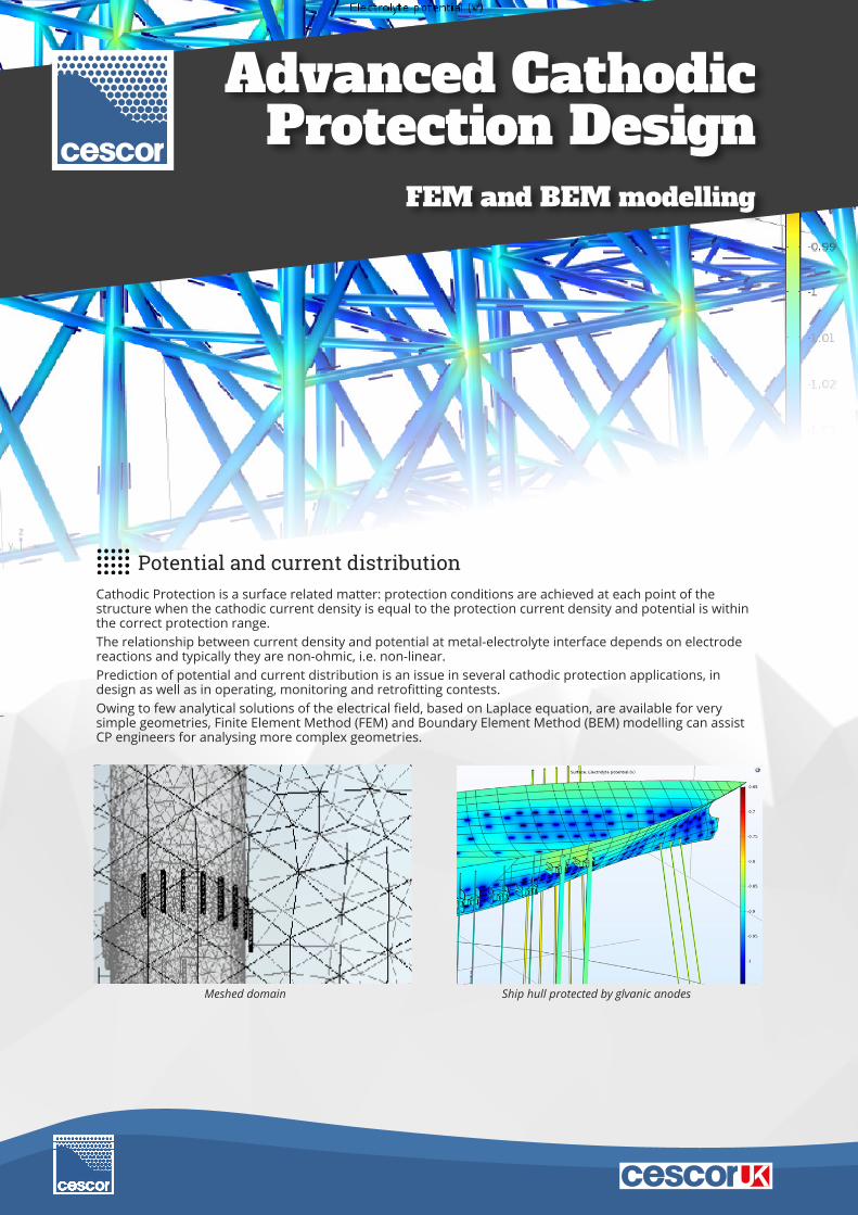
Cathodic Protection is a surface related matter: protection conditions are achieved at each point of the structure when the cathodic current density is equal to the protection current density and potential is within the correct protection range.The relationship between current density and potential at metal-electrolyte interface depends on electrode reactions and typically they are non-ohmic, i.e. non-linear.Prediction of potential and current distribution is an issue in several cathodic protection applications, in design as well as in operating, monitoring and retrofitting contests.Owing to few analytical solutions of the electrical field, based on Laplace equation, are available for very simple geometries, Finite Element Method (FEM) and Boundary Element Method (BEM) modelling can assist CP engineers for analysing more complex geometries.
Potential and current distribution
FEM and BEM modelling
Meshed domain Ship hull protected by glvanic anodes

Finite Element Method (FEM)
Finite Element Method is a numerical technique for solving boundary value problems. It minimizes an error function, generating a stable solution. It solves simple equations over small subdomains, i.e. finite elements, to approximate a more complex equation over a larger domain.FEM analysis takes into account for the primary current distribution related with electrolyte resistivity and the secondary current distribution related with electrode reactions.Boundary conditions are defined by considering the electrochemical behaviour of the metallic surface under protection, for example through the Tafel equations. The electrical field is then solved by considering the Laplace equation. Modelling with FEM allows to describe in realistic way the geometry of intricate structures and to study the large number of influence variables. It represents a useful tool for CP design, to evaluate impact and consequences of engineer’s choices on existing systems and predict different scenarios.
Aims and capabilities of modelling
Single Point Mooring Harbour sheet piling
Offshore Wind Farm monopile Platform jacket protected by impressed current system
• To verify that protection conditions are achieved all over the cathode, including recesses and shielded areas• To calculate the protection current density distribution and then the total protection current• In impressed current CP systems, to verify that overprotection potential thresholds were not exceeded• In linear structures, like pipelines, to calculate the maximum length which can be protected by anodes• To interpret monitoring potential readings• To assess the size of coating defects based on potential gradient measurements.
• Realistic virtual model of structures• Accurate knowledge of current and potential distribution• During design or retrofitting phase, possibility to find under-protected zones and to correct anodes or impressed current
systems position• Improved design of spacing, anode size, placing and other geometrical factors affecting cathodic protection distribution• Further verification and consolidation of C.P. design solutions• Possibility of determination of over-protected zones• Evaluation of galvanic anodes consumption• Help positioning potential probes inside complex structures• Analysis of the evolution over time of protection conditions
Advantages
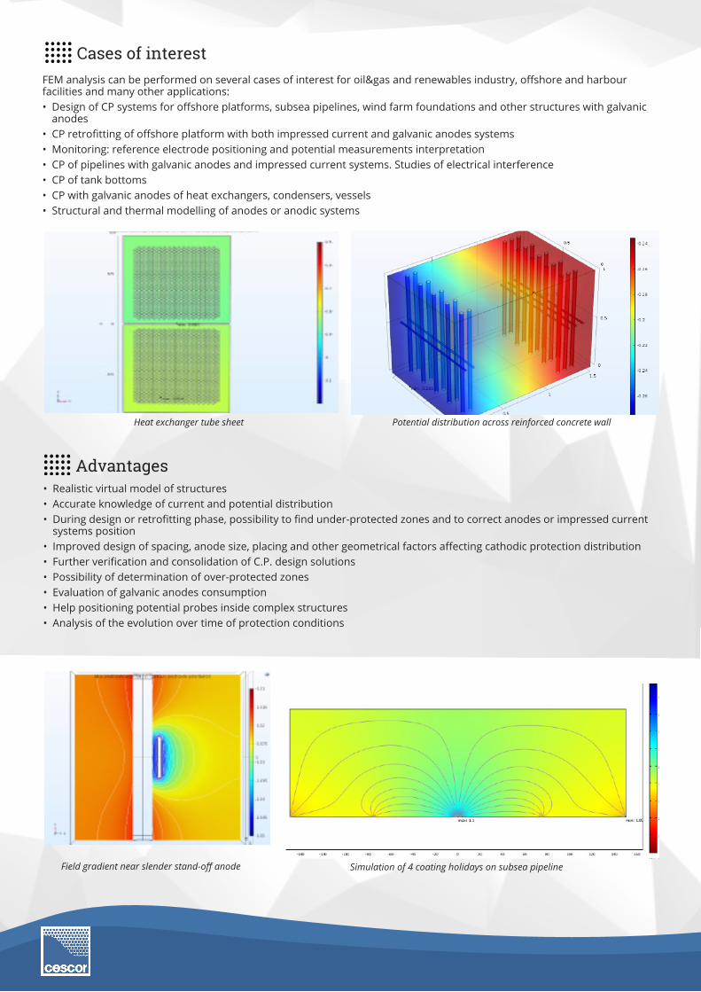
Heat exchanger tube sheet Potential distribution across reinforced concrete wall
Field gradient near slender stand-off anode Simulation of 4 coating holidays on subsea pipeline
Cases of interestFEM analysis can be performed on several cases of interest for oil&gas and renewables industry, offshore and harbour facilities and many other applications:• Design of CP systems for offshore platforms, subsea pipelines, wind farm foundations and other structures with galvanic
anodes• CP retrofitting of offshore platform with both impressed current and galvanic anodes systems• Monitoring: reference electrode positioning and potential measurements interpretation• CP of pipelines with galvanic anodes and impressed current systems. Studies of electrical interference• CP of tank bottoms• CP with galvanic anodes of heat exchangers, condensers, vessels• Structural and thermal modelling of anodes or anodic systems
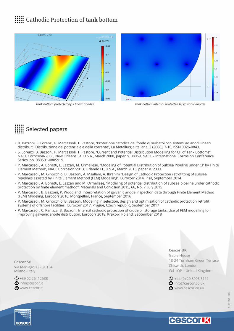
Tank bottom internal protected by galvanic anodesTank bottom protected by 3 linear anodes
Cathodic Protection of tank bottom
Selected papers
• B. Bazzoni, S. Lorenzi, P. Marcassoli, T. Pastore, “Protezione catodica del fondo di serbatoi con sistemi ad anodi lineari distribuiti. Distribuzione del potenziale e della corrente”, La Metallurgia Italiana, 2 (2008), 7-10, ISSN 0026-0843.
• S. Lorenzi, B. Bazzoni, P. Marcassoli, T. Pastore, “Current and Potential Distribution Modelling for CP of Tank Bottoms”, NACE Corrosion/2008, New Orleans LA, U.S.A., March 2008, paper n. 08059, NACE – International Corrosion Conference Series, pp. 080591-0805919.
• P. Marcassoli, A. Bonetti, L. Lazzari, M. Ormellese, “Modeling of Potential Distribution of Subsea Pipeline under CP by Finite Element Method”, NACE Corrosion/2013, Orlando FL, U.S.A., March 2013, paper n. 2333.
• P. Marcassoli, M. Ginocchio, B. Bazzoni, A. Msallem, A. Ibrahim “Design of Cathodic Protection retrofitting of subsea pipelines assisted by Finite Element Method (FEM) Modelling”, Eurocorr 2014, Pisa, September 2014.
• P. Marcassoli, A. Bonetti, L. Lazzari and M. Ormellese, “Modeling of potential distribution of subsea pipeline under cathodic protection by finite element method”, Materials and Corrosion 2015, 66, No. 7, July 2015
• P. Marcassoli, B. Bazzoni, P. Woodland, Interpretation of galvanic anode inspection data through Finite Element Method (FEM) Modeling, Eurocorr 2016, Montpellier, France, September 2016
• P. Marcassoli, M. Ginocchio, B. Bazzoni, Modeling in selection, design and optimization of cathodic protection retrofit systems of offshore facilities., Eurocorr 2017, Prague, Czech republic, September 2017
• P. Marcassoli, C. Panizza, B. Bazzoni, Internal cathodic protection of crude oil storage tanks. Use of FEM modelling for improving galvanic anode distribution, Eurocorr 2018, Krakow, Poland, September 2018
Rev. Sep. 2018
Cescor SrlVia Maniago 12 - 20134 Milano - Italy
+44 (0) 20 8996 5111
Cescor UKGable House18-24 Turnham Green Terrace Chiswick, London W4 1QP – United Kingdom
+39 02 [email protected]


![cathodic protection in practise · 2 [CATHODIC PROTECTION/BM] CATHODIC PROTECTION P E FRANCIS 1 INTRODUCTION The first practical use of cathodic protection is generally credited to](https://img.dokumen.tips/doc/110x75/5ace93c87f8b9ae2138b87e4/cathodic-protection-in-cathodic-protectionbm-cathodic-protection-p-e-francis.jpg)