Embed Size (px)
Citation preview

Vol. 10 No.1, February 2012 48
Design of Beam-Forming Networks for Multibeam Antenna Arrays Using Coherently Radiating Periodic Structures A. Arce*1, D.H. Covarrubias2 , M.A. Panduro3 , L.A. Garza4 1,2 Electronics and Telecommunications Department, CICESE Research Centre Carretera Ensenada-Tijuana 3918, 22860 Ensenada, Baja California, Mexico *[email protected] 3,4 Unidad Académica Multidisciplinaria Reynosa-Rhode, Universidad Autónoma de Tamaulipas Carretera Reynosa-San Fernando, 88779 Reynosa, Tamaulipas, Mexico
ABSTRACT The design of a beam-forming network (BFN) for a multibeam-steerable antenna array using Coherently Radiating Periodic Structures (CORPS) is presented. In this design, the input ports of the feeding network are optimized using the particle swarm optimization (PSO) algorithm. A two-beam design configuration of CORPS-BFN for a multibeam-steerable linear array is proposed and analyzed. The results shown in this paper present certain interesting characteristics in the array factor response, in terms of sidelobe level (SLL) and directivity (D), for the scannable multibeam linear array and the feeding network simplification for the design of BFN based on CORPS. Keywords: CORPS beamforming network, scannable multibeam antenna array, array factor.
RESUMEN En este artículo se presenta el diseño de una Red de Conformación de Haz (BFN) para un arreglo de antenas de haces múltiples y electrónicamente dirigibles utilizando Estructuras Periódicas de Radiación Coherente (CORPS). En este diseño las entradas complejas de la red de alimentación se consideran como variables de optimización empleando el algoritmo de optimización de enjambre de partículas (PSO). En este caso, se propone una configuración de diseño de dos haces de una CORPS-BFN para un arreglo lineal de haces múltiples electrónicamente dirigibles para su análisis. Los resultados presentados en este artículo ilustran ciertas características interesantes en la respuesta del factor de arreglo, en términos del nivel de lóbulos laterales (SLL) y la directividad (D), así como en la simplificación de la red de alimentación para el diseño de redes de conformación de haz basadas en CORPS. 1. Introduction Modern antenna applications such as multiple-Input and multiple-output (MIMO) systems and smart antennas have been suggested to service several spatially dispersed mobile users simultaneously [1]. Smart antennas may typically contain a switched-beam, based on beam-forming networks (BFN) or on fully adaptive configurations using phased arrays. Switched-beam arrays create fixed, simultaneous and multiple beams. On the other hand, adaptive arrays conform and direct the beam pattern by utilizing signal-processing algorithms [2]. Recently, a technology called Coherently Radiating Periodic Structures (CORPS) has been introduced in the field of electromagnetic research [3]. CORPS
as a beam-forming network has adaptive characteristics coupled with the generation of multiple orthogonal beams. The CORPS technological concept was introduced and applied to high resolution imaging systems in [3]. The methodology to implement CORPS technology as a beam-forming network for a phased array is proposed in [4]. Other research works present a general-purpose beam-forming network for scannable antenna arrays [5]-[6]. Finally, the recent research presents the efficiency of CORPS beam-forming networks in physical implementations [7], reinforcing the importance of this work.

Design of Beam‐Forming Networks for Multibeam Antenna Arrays Using Coherently Radiating Periodic Structures, A. Arce et al. / 48‐56
Journal of Applied Research and Technology 49
In this paper the particle swarm optimization (PSO) algorithm optimizes the required amplitude and phase excitations that should be introduced to the network. This design strategy satisfies the most important tradeoffs such as sidelobe level (SLL) and directivity (D) in an appropriate coverage range. The main contribution of this work is to propose the CORPS-BFN technology as an efficient and innovative beam-forming network alternative for a multi-beam antenna system. The CORPS-BFN improves performance over the usual way of feeding antenna arrays (i.e. direct feed to radiating elements). In this way, this novel network introduces interesting features that can be applied in a multi-beam communication scenario. The paper is organized as follows. Section 2 describes the CORPS ideal behavior implemented as a BFN, including mathematical assumptions related to the system operation and a description of the optimization process. The simulation set up and results are presented in section 3. Finally, conclusions of this work and future research directions are presented in section 4.
2. Theoretical study 2.1 CORPS-BFN Theoretical Model CORPS-BFN model considers the basic behavior principles of the periodic structures called CORPS [3], as a unit cell to conform a BFN [4]. This unit cell or basic node can act as split (S)-node or recombination (R)-node by changing its relative position but it is important to note that this unit cell is identical for both nodes. Detailed information about the characterization of the nodes can also be found in [4]. In this way the unit cell can be represented as a 3-port S-node characterized by the following scattering matrix:
2 2
2
2
0
[ ] 0 0
0 0
j j
jCell
j
S (1)
The matrix in (1) ensures that the unit cell is perfectly matched and isolated, and therefore there is no interaction between input signals. An entire feeding network can be integrated by iteratively alternating S and R nodes, as shown in Figure 1.
Figure 1. Diagram of CORPS-BFN with S and R nodes, of M inputs, N outputs and L layers.

Design of Beam‐Forming Networks for Multibeam Antenna Arrays Using Coherently Radiating Periodic Structures, A. Arce et al. / 48‐56
Vol. 10 No.1, February 2012 50
In Figure 1, the schematic of CORPS-BFN shows that it is feasible to establish several configurations with different inputs, outputs and layers that handle simultaneously several orthogonal beams according to the application. In order to calculate the fields at the output of the unit cell
1 2 3[ ] [ ]TCellV V V V in (1) we can use:
1 11 12 13 1
2 21 22 23 2
3 31 32 33 3CellCell Cell
V S S S V
V S S S V
V S S S V
(2)
where 1 2 3[ ] [ ]TCellV V V V is the complex
excitation (amplitude and phase) at the input ports of a unit cell. Evaluating (2) and interconnecting a diagram as in Figure 1, we can simulate and analyze a beam-forming network that uses CORPS technology which can be physically implemented, as in [4], [7]. At the top of the feeding network, we must consider the geometry used on the antenna array. In our case we consider an equidistant linear array for simplicity reasons (one dimension). Its array factor for a set of complex inputs [a] feeding CORPS-BFN is given by the next equation [8]:
a ( cos )
1( , ) n
N jkdnn
AF I e
(3)
where nI represents the complex excitation of the
nth radiator of the array, nd is the position of the
antenna element n, 2k is the phase constant
and is the angle with respect to the normal that indicates the direction of radiation in the space. The complex inputs feeding the CORPS network consider the proposed inputs and a progressive phase excitation, given by
( ) ( )i ij ji ia A e e
(4)
for 1 i N L , where L is the number of
layers of the CORPS network and the term i in
the exponential is
0cosi ikdm
(5)
where 0 is the direction of maximum radiation
and
i i
Mdm d
M L
(6)
In (6) 1M N , where M is the number of inputs of the network that electronically control the radiation pattern.
The term ( )ije in (4) adds a phase excitation in the complex inputs of the feeding network related to a linear interpolation of a conventional progressive phase excitation. Due to the number of possible input combinations, finding a set of complex excitations that result in a radiation pattern that meets specific objectives represents an NP-hard (non-deterministic polynomial-time hard) problem, for this reason population-based stochastic optimization algorithms are suggested with the benefit to handle multimodal, non-convex and nonlinear optimization problems [9]. The optimization process followed to obtain near-optimal solutions to the complex inputs to feed the BFN is described in the next section. 2.2 Optimization Process The optimization process in CORPS-BFN is used to obtain complex excitations (amplitudes and phases) that should be directly applied at the input ports of the network. In this paper, these excitations are determined by a population-based meta-heuristic called particle swarm optimization (PSO). The PSO algorithm as an optimization tool offers valuable features such as the fact that each individual in the population has a basic type of “memory”, ease of implementation and small number of parameters to be selected and tuned in one operator (velocity), compared with other population-based methods, including genetic

Design of Beam‐Forming Networks for Multibeam Antenna Arrays Using Coherently Radiating Periodic Structures, A. Arce et al. / 48‐56
Journal of Applied Research and Technology 51
algorithms (GA), where the memory concept relies on few individuals (elitism) and the parameters to be selected and tuned are related to multiple operators (selection, crossover and mutation operators). The behavior of PSO can be summarized in the
velocity operator tkdv and position equations
tkdx ,
respectively [9], given by
1t t tkd kd kdx x v
(8)
where is the inertial weight, 1c and 2c are the
acceleration constants. The terms represented by are random numbers uniformly distributed in
0,1U . The current personal best and global best
are represented by *kdp and *
dg , respectively.
Detailed information of the terms can be found in [10], and the implementation steps of the PSO algorithm are summarized in the pseudo-code shown below. Algorithm. pseudo-code of particle swarm optimization Particle Swarm Optimization
Objective function 1( ), ( ,..., )Tpf x x x x
Initialize locations kdx and velocity kdv of nparticles
Find *dg from 1min{ ( ),..., ( )} (at 0)nf x f x t
while (criterion) 1t t (pseudo time or iteration counter) for loop over all n particles and all d dimensions
enerate new velocity tkdv using equation (7)
Calculate new locations tkdx using (8)
Evaluate objective functions at new locations tkdx
Find the current best for each particle *kdp end for
Find the current global best *dg end while
Output the final results *kdp and *
dg
In this work, the PSO algorithm is used just as an optimization tool for all the advantages presented in this section, the performance evaluation between the PSO algorithm and other algorithms in this application is outside the scope of this paper. Finally, the objective function to address the tradeoff between SLL and directivity (D) is set as follows: The goal is to minimize the weighted sum that involves both objectives (SLL and D) in the cost function, SLL is the angle where the maximum
level of SLL is located in (9). The objective function only computes two related restrictions but a greater number of objectives can be treated and will be discussed in a future study. The simulation scenario and results obtained are described below. 3. Simulation set-up and results 3.1 Simulation case study To demonstrate the potential of CORPS technology applied to a beam-forming network that feeds a set of antenna elements, we proposed the next two-beam design configuration for simplicity reasons as follows: The configuration proposed shown in Figure 2 is a linear array system of 20 array antenna elements
1 * 1 * 11 1 2 2 ,max( ) ( ),t t t t t
kd kd k kd kd k d kd k dv v c p x c g x v v d (7)
min ( , ) / max ( , ) 1/ ( , )SLLOf AF a AF a D a
(9)

Design of Beam‐Forming Networks for Multibeam Antenna Arrays Using Coherently Radiating Periodic Structures, A. Arce et al. / 48‐56
Vol. 10 No.1, February 2012 52
with 19 feeding ports (i.e. M=19 and N=20) implemented as a CORPS-BFN of one layer, with 10 complex inputs to control 11 antennas (beam #1) and 9 complex inputs to control 10 antennas (beam #2). In this manner, for this particular configuration an orthogonal signal could be conformed and controlled by the first 10 of the 20 feeding ports and the other 9 remaining to be used for another orthogonal signal, thus both signals can be scanned towards the same or different spatial locations. The objective is to evaluate the behavior of the array factor generated by the configuration of CORPS-BFN for a multibeam-steerable linear array. The evaluation of the array factor considers a steering range of 80 degrees, with an angular step of 10 degrees for a 20 elements antenna array and a uniform spacing between antenna elements of λ/2. In the same way, PSO was implemented for the optimization with the following parameters: The optimization is executed using 200 individuals throughout 500 iterations to ensure a good sampling of the solution space, a global topology of PSO is used with a time-varying inertial weight ( ) that varies from 0.9 to 0.4 throughout the iterations, the acceleration constants ( 1 2,c c ) are set to 2.0 and the maximum
allowed velocity ( ,maxdv ) is set as r where
,max ,min( )d dr v v [11-13].
The obtained results from simulations are explained below. 3.2 Simulation results To perform a comparative analysis of the linear array system that considers CORPS as a feeding network and the system without it, we propose the next case study: the case of a uniform linear array (ULA) without optimization, i.e. the natural response of the array, in the same way we studied the behavior of the array factor for linear array considering the optimization of amplitude and phase without the use of CORPS-BFN. And finally, the case that considers a linear array in CORPS-BFN with a proposed configuration (Figure 2). This study provides us information about the tradeoff between performance of the system in different configurations to conform a steerable radiation pattern in SLL and directivity. Moreover, in the case of the CORPS-BFN the simplification of the network in terms of the components used for the BFN is observed. To make a fair analysis in this case study, the behavior of one conformed beam is studied and the number of control signals (inputs of the system) used to control the beam were the reference (Figure 3 and Figure 4). Figures 3 and 4 show the performance in sidelobe level and directivity of the array, respectively, considering in both different design configuration cases and taking into account 10 control signals inputs for controlling just one beam through the scanning range between 050º 130º , with an
angular step of 10°.
Figure 2. Proposed configuration of CORPS-BFN: ULA system of 19 feeding ports and 20 antenna elements
considering 10 inputs x 11outputs for beam #1 and 9 inputs x 10 outputs for beam #2.

Design of Beam‐Forming Networks for Multibeam Antenna Arrays Using Coherently Radiating Periodic Structures, A. Arce et al. / 48‐56
Journal of Applied Research and Technology 53
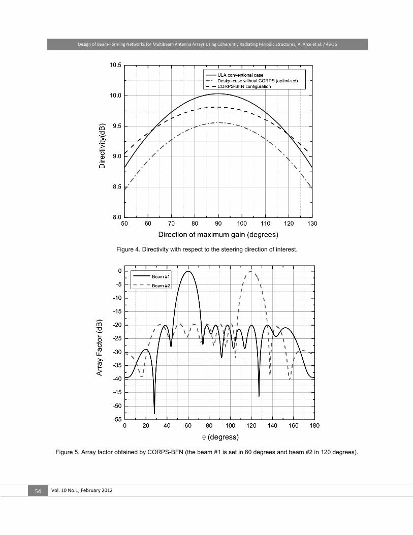
In Figure 3 the isolation level from the main beam with respect to secondary lobes in different directions of interest are evaluated. The ULA conventional case is outweighed by the design case that optimizes both amplitude and phase perturbations by PSO without CORPS reaching slightly higher values under -20dB in all the steering range. On other hand, the behavior of CORPS-BFN configuration reaches the best performance with numerical values under -24dB when the direction of interest is near broadside region The directivity in different spatial directions of interest is evaluated in Figure 4, showing similar values of directivity between the optimized case without CORPS and the CORPS case with respect to the ULA conventional case, with values between 9.5 to 10 dB at 90 degrees for the three cases.
It is interesting to note that the values of SLL shown in Figure 3 achieving a better performance by CORPS case and the directivity near the ULA case configuration reached by the same CORPS configuration in Figure 4, relies in that CORPS-BFN allows handling more antenna elements (in this case 11 antenna elements) with just 10 signal control inputs (i.e. CORPS-BFN of one layer), showing that a network simplification can be made, reducing the number of signal control inputs to handle more antenna elements to improve the performance. The only disadvantage shown by the simulations is related to the visibility window of approximately 70° which maintains the sidelobe level under -20dB in this confined area (see Figure 3). Despite the above, CORPS-BFN has unique features that make it a good candidate for beam-forming networks.
Figure 3. Side lobe level with respect to the steering direction of interest.
Design of Beam‐Forming Networks for Multibeam Antenna Arrays Using Coherently Radiating Periodic Structures, A. Arce et al. / 48‐56
Vol. 10 No.1, February 2012 54
Figure 4. Directivity with respect to the steering direction of interest.
Figure 5. Array factor obtained by CORPS-BFN (the beam #1 is set in 60 degrees and beam #2 in 120 degrees).
Design of Beam‐Forming Networks for Multibeam Antenna Arrays Using Coherently Radiating Periodic Structures, A. Arce et al. / 48‐56
Journal of Applied Research and Technology 55
In Figure 5, an example is shown of the radiation pattern of two-beam system conformed by the configuration proposed optimized with PSO, showing the CORPS-BFN capabilities to handle SLL and directivity to specific spatial locations. The orthogonal beams can scan the main beam towards the same direction of interest, with the advantage of not being a switched beam-forming network (e.g., Butler matrix) and control a fully adaptive radiation pattern. The array factor behavior conformed by the CORPS system is shown in Figure 5; the direction of interest is set in 0 60° for beam #1 and 0
120° for beam #2. This particular configuration of CORPS only permits to control a subset of antenna elements of the array for each beam pattern. However, the desired SLL could remain in
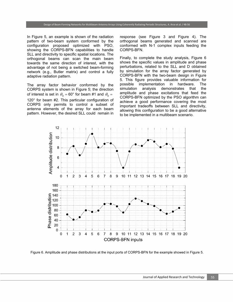
response (see Figure 3 and Figure 4). The orthogonal beams generated and scanned are conformed with N-1 complex inputs feeding the CORPS-BFN. Finally, to complete the study analysis, Figure 6 shows the specific values in amplitude and phase perturbations, related to the SLL and D obtained by simulation for the array factor generated by CORPS-BFN with the two-beam design in Figure 5. This figure provides valuable information for possible implementation in hardware. The simulation analysis demonstrates that the amplitude and phase excitations that feed the CORPS-BFN optimized by the PSO algorithm can achieve a good performance covering the most important tradeoffs between SLL and directivity, allowing this configuration to be a good alternative to be implemented in a multibeam scenario.
Figure 6. Amplitude and phase distributions at the input ports of CORPS-BFN for the example showed in Figure 5.

Design of Beam‐Forming Networks for Multibeam Antenna Arrays Using Coherently Radiating Periodic Structures, A. Arce et al. / 48‐56
Vol. 10 No.1, February 2012 56
4. Conclusions The design of a multibeam BFN based on a configuration of CORPS for scannable antenna arrays using optimization has been introduced. Simulation results reveal that the design of multibeam CORPS-BFN optimizing the complex inputs with PSO algorithm could cover the most important requirements to feed antenna arrays. The CORPS-BFN configuration studied and analyzed showed the advantages and drawbacks of adopting this technology; highlighting the support to conform orthogonal multiple beams with the reduction of control signal inputs (simplification of the BFN) to electronically scan the beam pattern over a wide range. Particularly, the CORPS-BFN configuration based on the control of a subset of antenna elements for each beam pattern demonstrated a good performance fulfilling the essential requirements in terms of SLL and directivity. Depending on the design requirements (scanning, directivity and the simplification of the network), a suitable configuration can be set. Future work will deal with different CORPS-BFN configurations (e.g., more layers) and designing CORPS-BFN for multibeam planar (bidimensional) arrays searching to extend the advantages of the system. References [1] M. Döttling, W. Mohr, and A. Osseiran, Radio Technologies and Concepts for IMT-Advanced, 1st ed. Chichester, England: Wiley, 2009. [2] R. Mailloux, Phased array antenna handbook, 2nd ed. Boston, MA: Artech House, 2005. [3] R. Garcia, D. Betancourt, A. Ibañez, and C. del-Rio, “Coherently radiating periodic structures (CORPS): a step towards high resolution imaging systems?,” IEEE AP-S 2005, Washington, DC, 2005. [4] D. Betancourt and C. del Rio Bocio, “A Novel Methodology to Feed Phased Array Antennas,” IEEE Transactions on Antennas and Propagation, vol. 55, no. 9, pp. 2489-2494, 2007. [5] M. A. Panduro and C. del Rio Bocio, “Design of Beam-forming Networks for Scannable Multi-beam
Antenna Arrays using CORPS,” Progress In Electromagnetics Research, vol. 84, pp. 173-188, 2008. [6] M. A. Panduro and C. del Rio-Bocio, “Design of beam-forming networks using CORPS and evolutionary optimization,” AEU International Journal of Electronics and Communications, vol. 63, no. 5, pp. 353-365, May. 2009. [7] N. Ferrando and N.J.G. Fonseca, “Investigations on the Efficiency of Array Fed Coherently Radiating Periodic Structure Beam Forming Networks,” IEEE Transactions on Antennas and Propagation, vol. 59, no.2, pp. 493-502, Feb. 2011. [8] C. A. Balanis, Antenna Theory: Analysis and Design, 3rd ed. Hoboken, NJ: Wiley-Interscience, 2005. [9] A. E. Eiben and J. Smith, Introduction to Evolutionary Computing, 1st ed. New York, NY: Springer, 2003. [10] R. C. Eberhart, Y. Shi, and J. Kennedy, Swarm Intelligence, 1st ed. San Francisco, CA: Morgan Kaufmann Publishers, 2001. [11] A. Arce, D. H. Covarrubias, and M. A. Panduro, “Performance Evaluation of Population Based Optimizers for the Synthesis of Linear Antenna Arrays,” Proc. of the 6th IASTED Int. Conf., vol. 649, pp. 044–103, 2009. [12] R. Eberhart and Y. Shi, “Particle swarm optimization: developments, applications and resources,” Proc. Cong. Evol. Comput., vol. 1, pp. 81-86 vol. 1, 2001. [13] N. Jin and Y. Rahmat-Samii, “Advances in Particle Swarm Optimization for Antenna Designs: Real-Number, Binary, Single-Objective and Multiobjective Implementations,” IEEE Transactions on Antennas and Propagation, vol. 55, no. 3, pp. 556-567, 2007. Acknowledgements This work was supported by the Mexican National Science and Technology Council, CONACyT, under grant 127919 and the Science and Technology Council of Tamaulipas Mexico COTACyT under grant 108166.