Embed Size (px)
Citation preview

Design of a Compact, Battery Powered, and Fiber Optic Controlled Remotely Operated Vehicle
Heather Brundage, Michelle Aquing, Lauren Cooney, Bridget Downey,
Eddie Huo, Albert Kwon, M. Jordan Stanway, Thaddeus Stefanov-Wagner, Kurt Stiehl, Daniel Walker
Massachusetts Institute of Technology
Abstract - Developed for the 4th Annual Marine Advanced Technology Education (MATE) Center’s Remotely Operated Vehicle (ROV) competition, Tim the ROV was designed and built by MIT’s ROV team to compete in the Explorer Class division. Capable of operating at depths of 40 feet and completing tasks such as fluid collection, temperature measurements, and object retrieval in less than 30 minutes, Tim was designed to be small and highly maneuverable. To aid in maneuverability, Tim is equipped with on-board power and a passive-spooling, single-strand fiber optic tether. Tim’s compact layout and powerful thrusters also contribute to the main design goal – build a small, highly maneuverable ROV capable of competing in the MATE ROV competition.
I. INTRODUCTION
At the beginning of 2005, MATE posted the specifications for their annual ROV competition. The Explorer Class mission consisted of four tasks to be completed in less than 30 minutes, while at a depth of 40 feet. These tasks were: 1) connecting a ‘fiber optic communication link’, 2) retrieving three ‘data probes’ from the drawer of a ‘science package’, 3) collecting an undiluted fluid sample, and 4) measuring the temperature of an upward current. From past experience, the MIT ROV team learned that maneuverability and size are major factors in completing a successful mission. Identifying those factors as top priorities, the team aimed to build an ROV that would fit into a twelve-inch cube, be controlled through a minimal tether, and complete all four mission tasks.
In order to meet this goal, the team took a new approach this year - powering the vehicle with on-board batteries and using a fiber optic tether. Both of these decisions brought increased complexity, but provided substantial benefits. Using on-board batteries resulted in stricter power restrictions (only 12 volts and 24 amps could be used) and increased the weight and size of the ROV. However, on-board power also allowed for a significantly reduced tether diameter and eliminated power loss issues involved in low voltage powering through a long tether. Since power no longer needed to be passed down the tether, the ROV only needed data and video to reach the surface, a task elegantly accomplished with fiber optics.
Since these two systems were new to the team, the rest of the vehicle was kept as simple as possible. This aim, along with the goal of keeping the ROV very small and highly maneuverable, drove the design of the rest of vehicle, resulting in Tim, the ROV (Fig. 1).
Fig. 1. Tim the ROV
II. VEHICLE DESIGN
A. Power System
The team’s power system design changed radically this year. In previous years, an on-deck lead acid battery provided power to all ROV systems. This method of power offered cheap, reliable, high-capacity energy storage. Power was transferred to the ROV through four strands of twelve gauge wire. Even with such thick cable, the transmission losses ranged upwards of five volts under high load conditions. This voltage sag resulted in camera failures and transients within the control system. The thick cable also resulted in a bulky tether that pulled the ROV around, instead of the ROV pulling the tether. As a result, this year the team decided to implement onboard power storage.
In order to make this decision a reality, many factors had to be considered. These included: competition power restrictions, space limitations, and battery chemistry options. The ROV competition specifications restricted on-board power to 25 amps at 12 volts. The team goal of keeping the ROV as small as possible meant the batteries had to be as small and light as possible. The issue of which battery chemistry to use was more complicated.
Several options were considered, each with their own benefits and drawbacks. Lead acid batteries cheaply offered significant capacity and easy recharging. However, lead acid batteries are also very heavy and bulky. Nickel cadmium (NiCd) batteries offered somewhat more capacity for a given
1
weight and volume, but are more difficult to charge and are significantly more expensive. Nickel metal hydride (NiMH) batteries have almost twice the capacity of nickel cadmium batteries given the same weight and volume. However, they are more expensive and similarly hard to charge. Lastly, lithium ion (Li-Ion) batteries could be used. Though they have the greatest power density, they are costly and difficult to charge and handle.
After comparing the options, the team decided to use ten size M NiMH batteries (Fig. 2), as they offered the necessary capacity within the team’s price range. The size M batteries are 20 amp hour at a nominal 1.2 volts. They are 41.5 mm (1.63 in.) in diameter and 91.2 mm (3.6 in.) high – slightly larger than a a D cell battery. Using ten of these batteries in series, the ROV could run 12 volts at 25 amps for well over 30 minutes.
Fig. 2. Size M NiMH battery
Before the batteries could be used, they had to be
connected in series and placed in a waterproof housing. Since the team aimed to keep each dimension less than twelve inches, the batteries were divided into two packs, each with five batteries. These packs fit on the bottom of the ROV, one on each side. In order to ensure a waterproof housing and reduce complexity, the team decided to use Otterboxes, rated to 100 feet, for the battery housing. The batteries are laid side by side in the boxes and thin strips of copper are soldered terminal to terminal to connect the cells together (Fig. 3). The soldering process proved to be a challenge. It was difficult to get a good hot solder joint while still keeping the batteries cool. In the end, the parts were cleaned with a flux pen and a 260 watt soldering iron was used. Two sets of battery packs were built to allow one set to be used while the other was charging. They can be easily disconnected from the main system using waterproof bulkhead connectors from Impulse Enterprises.
Fig. 3. One of two battery packs, complete with five NiMH battieries and a 30A fuse.
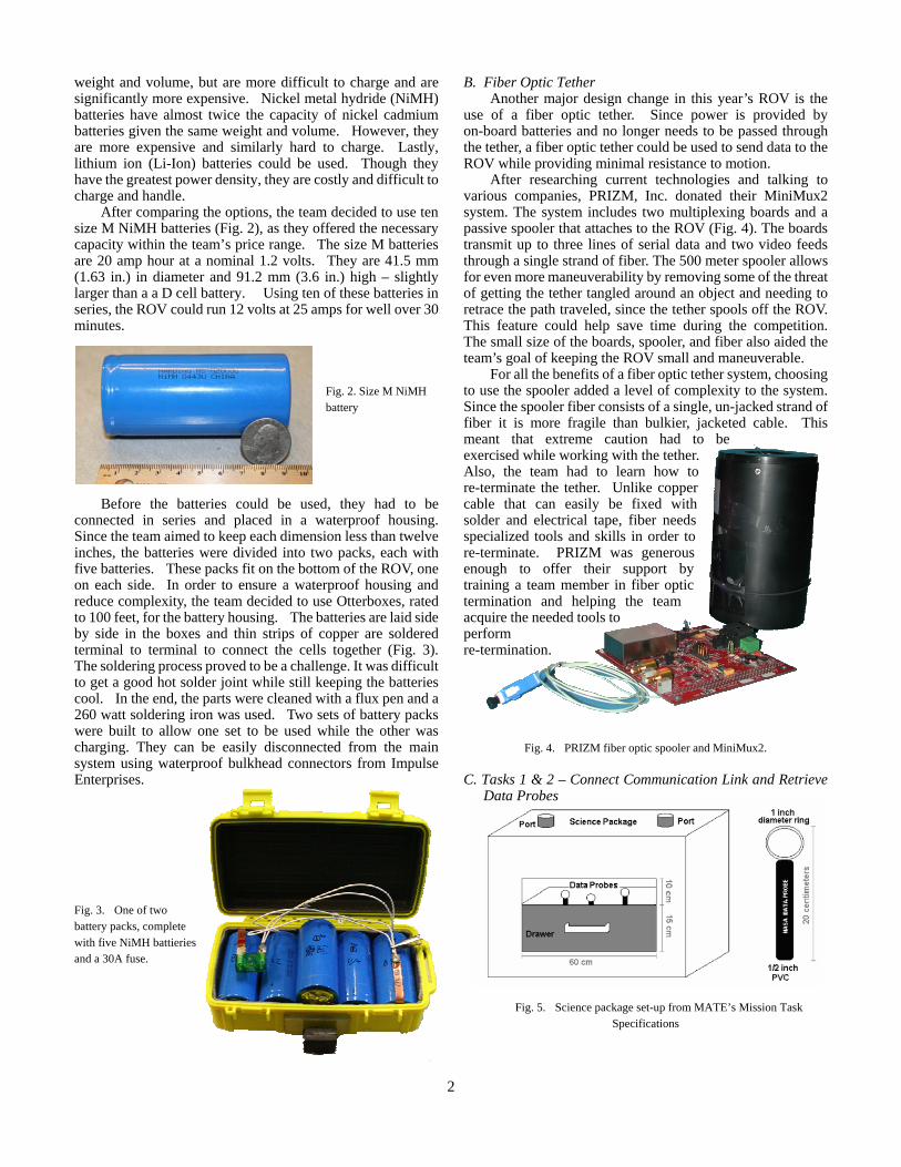
B. Fiber Optic Tether Another major design change in this year’s ROV is the
use of a fiber optic tether. Since power is provided by on-board batteries and no longer needs to be passed through the tether, a fiber optic tether could be used to send data to the ROV while providing minimal resistance to motion.
After researching current technologies and talking to various companies, PRIZM, Inc. donated their MiniMux2 system. The system includes two multiplexing boards and a passive spooler that attaches to the ROV (Fig. 4). The boards transmit up to three lines of serial data and two video feeds through a single strand of fiber. The 500 meter spooler allows for even more maneuverability by removing some of the threat of getting the tether tangled around an object and needing to retrace the path traveled, since the tether spools off the ROV. This feature could help save time during the competition. The small size of the boards, spooler, and fiber also aided the team’s goal of keeping the ROV small and maneuverable.
For all the benefits of a fiber optic tether system, choosing to use the spooler added a level of complexity to the system. Since the spooler fiber consists of a single, un-jacked strand of fiber it is more fragile than bulkier, jacketed cable. This meant that extreme caution had to be exercised while working with the tether. Also, the team had to learn how to re-terminate the tether. Unlike copper cable that can easily be fixed with solder and electrical tape, fiber needs specialized tools and skills in order to re-terminate. PRIZM was generous enough to offer their support by training a team member in fiber optic termination and helping the team acquire the needed tools to perform re-termination.
Fig. 4. PRIZM fiber optic spooler and MiniMux2.
C. Tasks 1 & 2 – Connect Communication Link and Retrieve
Data Probes
Fig. 5. Science package set-up from MATE’s Mission Task
Specifications
2

The first task required the ROV to descend through a 60 cm (23.6 in.) square hole through the ‘ice’ with a ‘communication link’ and connect the link (a PVC dive stick attached to CAT-V cable) to the science package (Fig. 5). The second task required the ROV to open a drawer on the science package and retrieve three ‘data probes’ (similar PVC dive sticks).
When deciding how to complete the second task of retrieving the probes, the main goal was to design a passive system that would quickly retrieve all the probes. The team had hoped to find a way to descend on the probes, grabbing all three at once, and then ascending again. The mission descriptions were not specific enough to design for this, however, and a relatively simple cork-screw design resulted (Fig. 6). In order to keep the system simple and compact, the same method was used to carry the communications link to the connector. This dual use of the corkscrew prevented the need to deal with more appendages on the vehicle that could impede Tim’s movement. The design also decreased the complexity of trying to add a gripper to the vehicle.
Fig. 6. Corkscrew manipulator used to carry the
‘communication probe’ and to collect ‘data probes.’
In order to retrieve the probes, Tim first has to open the drawer. Though many ideas were considered for the drawer opener, the goal of simplicity won out and a completely passive hook was designed to use the thrust from the ROV in order to open the drawer. This passive design required no motors and, thus, reduced space, power and complexity requirements over active alternative designs. D. Task 3 – Collect a Fluid Sample
Again, simplicity, size and power constraints guided the design for task number three – collecting a sample of fluid from a crevice. Similar to last year’s solution, the design for our system is based on two flexible collection bags. These flexible, empty bags prevent any net change in buoyancy when the sample is collected, as no air volume is displaced during collection. A funnel is used to aid in targeting the crevice, and a windshield washer pump is adapted to suck the sample into the bags (Fig. 7). This pump is an improvement over the bilge pump used in the past because it has 10 percent of the internal volume and therefore requires less fluid for priming. This means less dilution in the collected sample.
To provide a completely undiluted sample, a passive rejection system is used. The sample flows straight through a t-junction into a dummy bag, collecting the water that initially fills the pump as primer. Once this dummy bag is filled, the fluid passes through the upward leg of the t-junction, and into the 500 mL sample bag. This passive rejection system relies on the momentum of the priming fluid to prevent it from entering the sample bag prematurely. It has performed flawlessly in many bench tests, and fills the 500 mL sample bag in 20 seconds.
Fig. 7. Fluid collection system E. Task 4 – Measure Temperature
In order to fulfill the fourth mission requirement of measuring the temperature of a venting fluid, Tim is equipped with a temperature sensor based on a resistance temperature detector (RTD). An RTD changes resistance linearly with temperature, so it is easy to calibrate, and provides an easy to measure voltage output.
Since the temperature of liquid water is being measured, the range of the RTD below 0º Celsius was considered unnecessary. In order to cut that range out of the measurements, the RTD was connected to a Wheatstone bridge (Fig. 8). Resistors were carefully matched near the 0˚C RTD resistance, balancing the bridge at a low temperature. The end result was a sensor that measures down to -7˚C.
In order to maximize resolution, an instrumentation amplifier was also incorporated into the design. Since the analog to digital channels on the control system are 12 bits, an analog signal in is translated from 0-5 volts to the equivalent integer value of 0-2^12 (4096). This restricts the measurement to be within 0-5 volts. The resolution of the measurement is inversely proportional to the range of temperatures contained in that 0-5 volts. Assuming the temperature of the vent would be no greater than 60ºC, the output measurement was amplified so that a 5 volt signal corresponds to 61˚C. The amplifier also serves to provide a clean signal over the line from the sensor to the main electronics box.
Fig. 8. RTD in Wheatstone bridge and amplifier circuit
3

Fig. 9. Temperature Calibration Bench top calibration was performed by starting with a
container of ice water, a calibrated digital thermometer, and a water heater. The sensor was powered, and temperature was recorded from the thermometer while voltage was recorded from the sensor. Hot water was added and stirred in to raise the temperature between measurements. The data was plotted and a linear fit was generated. The result was a calibration line with an R2 of 0.9845 (Fig. 9). This calibration line gives the sensor readout in increments of 0.0167ºC.
The RTD and its supporting circuitry are housed in a 2.54 cm (1 in) diameter polyethylene cylinder, sealed with an o-ring and filled with urethane potting compound for waterproofing. The RTD communicates with the main electronics box via a wet-pluggable Impulse Enterprises cable and two bulkhead connectors (Fig. 10).
Fig. 10. RTD sensor package F. Video
In order to complete the mission tasks and drive the ROV, the team determined that four video cameras were needed. Though there were many cameras to choose from, the team decided to use color cameras with a built in LED light ring (Fig. 11). These cameras were used on past MIT ROVs, were readily available, required minimal power, and were small and easy to mount. Since the fiber optic multiplexers supported two video feeds, a team member designed a video switching board, which was installed on the ROV and allowed the ROV operator to choose any two views to be sent up the tether.
Fig. 11. CAD Model of camera G. Pressure Sensor
Though not required for the mission tasks, the team decided it would be advantageous to have depth measurements for closed-loop depth control, since controlling the vertical motor by hand has proven difficult in the past. The pressure sensor selected for the ROV is a differential membrane/strain-gauge type sensor which outputs a voltage proportional to the pressure difference across the membrane. One port of the sensor is left open to the control box, which is sealed at atmospheric pressure. The other port connects to a plumbing fitting that is open to the water. The sensor measures 0-206 kPa (0-30 psi), providing useful readings up to a depth of 20 meters (66 ft.).
Since it is part of a family of sensors, it can be easily traded to extend the operating depth of the closed-loop control. These sensors can be more expensive, however, and are less accurate over smaller ranges. Using this sensor, pressure measurements are input to the control system through a 12-bit analog to digital channel, providing depth measurements to a resolution of 4.9 mm.
Fig. 12. Pressure Sensor
H. Control System The ROV has two Microchip PIC embedded
microcontrollers that make up its control system (Fig. 13). They communicate through a standard RS-232 serial connection running at 9600 baud. Embedded controllers were chosen because of their low cost, small size, and selection of onboard analog, digital, and timed pins.
Every 1/10th of a second, the bottomside controller tells the topside controller that it is functioning, and provides the ROV operator with useful data like depth, speed, and temperature. The topside control responds by telling the bottomside controller any new instructions from the pilot. This is called a master-slave arrangement; the bottomside controller is the master, and the topside controller is the slave. The bottomside controller was chosen to be the master
4

because it is more important than the topside control: it needs to create motor signals, read sensors, and implement feedback. It does this much faster than the operator and topside controller are able to give it instructions. As a result, it is more efficient to make the topside controller wait for the bottomside controller, rather than vice versa.
Fig. 13. Control System Layout I. Thrusters
Two main thrusters provide lateral and vertical motion. The thrusters were designed to be small, streamlined, waterproof, and powerful. Again this was driven by the goal of increased maneuverability. The main components are the motor and gearbox, the front spindle, back cap, main tube, propeller, and cowling (Fig. 14). The motor and gearbox provide the necessary rotational velocity to spin the propeller in the water. The motor is a 150 watt drill motor from Black and Decker. The original casing and clutch were removed, leaving only the motor and gearbox. The front spindle houses dual angular contact bearings, which constrain the propeller shaft in all directions except inline rotation (Fig. 15). It also couples the propeller drive shaft to the output of the planetary gearbox. This allows the propeller to spin without applying off-axis or thrust loads on the motor. The main tube and back cap form the pressure housing with the front spindle. A Parker Flexi-Seal is used to prevent water from entering the housing at the shaft.
The propeller provides thrust when spun, and the cowling decreases wasted thrust from the propeller. The cowlings also contribute to operator safety and lower the risk of breaking the fiber optic tether.
Two smaller motors are mounted on the side of the ROV to provide translational motion. Though the additional motors add complexity, they also allows for another degree of motion. This improves vehicle maneuverability and speeds mission completion.
Fig. 14. Main Thruster
Fig. 15. Section View of Front Spindel J. Floation
The method of buoyancy chosen for the ROV was structural polyurethane foam. This foam was a donation from a project in the MIT Towing Tank, and came highly recommended because it is easy to machine and low in density. The depth rating of the foam also exceeds the competition requirements.
III. FUTURE IMPROVEMENTS
In designing and building Tim, many design options were not pursed due to time and budget constraints. Many of these ideas, if realized, could improve or simplify the ROV greatly. Some of these ideas will be explored more fully in the future, for more advanced iterations of the ROV.
Onboard power was a big change in the team’s implementation for this year’s ROV, but the power system still has a lot of room for improvement. Designing a safe, reliable, quick-charge circuit for the battery packs would allow more ROV operation time without the added cost of more batteries. This task will be among the first to be addressed in the future. The type of battery used on the ROV is another point for improvement. Using Lithium-Ion rechargeables, instead of Nickel Metal-Hydride batteries, would reduce vehicle weight and volume, ultimately enabling a smaller vehicle with similar capabilities. This improvement is largely due to the difference in energy density between the two chemistries. Li-ion chemistry yields 110-160 Wh/kg, while NiMH only yields 60-120 Wh/kg. That’s a 25-45 percent improvement if Li-ion batteries are used. These would present difficulties, however. Li-ion batteries require a controlled charging circuit. They are also more prone to overheating and catastrophic failure.
Bearings
Another point of potential improvement is in the thruster seals. The flexi-seals used on this year’s ROV work well and are designed for dynamic sealing applications, but there is still a hole in the housing where water could leak in if the seal wears out or is damaged. One other type of dynamic seal eliminates this failure mechanism almost entirely. Use of a magnetic coupling between the motor and the propeller would eliminate most chances of leaking since there is no shaft breach in the motor housing. Some further research and
Motor
Gearbox Seal
5

aggressive design work will be necessary to realize a reliable coupling small enough to use effectively.
A further extension of that same principle would lead to a fully sealed, rim-driven propulsor. This is basically like a brushless DC motor with permanent magnets embedded in the tips of the propeller. The motor coil is housed in a shroud around the propeller, and drives it directly, without a shaft. These propulsors are generally more efficient than conventional thrusters, especially when considering thrust in both directions. This is because they are inherently ducted and the motor housing does not block the flow to the propeller. These propulsors also require very precise tolerances and detailed engineering, meaning a lot of development time.
Tim could also be made with only two thrusters, each having freedom to rotate about two axes, thus enabling thrust to be produced in any direction. This concept presents some challenging issues in implementation and waterproofing, as well as requiring a complex control model to drive it. One team members is researching this potential system, as part of a senior thesis.
While it is generally better to reduce the number of actuators on any system, leaving less room for Murphy’s law to act, one of the potential improvements considered was equipping the cameras with pan and tilt capability. This could be done with small servos, but was not a top priority, so will probably remain untouched until all the more beneficial improvements have been carried out. Other generally useful improvements that have been on the low priority list include laser ranging/measurement, conductivity (salinity) measurement, light measurement, and an integrated compass.
IV. CONCLUSION
Beginning the year with specific goals helped streamline the design process. Though time constraints towards the end led to quick fixes that increased the size of the vehicle, the team was able to meet most design goals. Many new technologies were explored, increasing the knowledge base of the team and better preparing the team for future competitions. Though complications during the competition led to the fiber tether tangling with the ‘communication link’ cable and hindering performance, Tim operated at depth and most systems were able to be tested and performed as expeceted. Next year the team hopes to use its exerpiences from this year to better implent on-baord power and fiber optic tether systems. Completing more predesign is another goal, in order to prevent last minute fixes and improve vehicle presentation. Overall, Tim was a success – a plotform to test new technology and tackle intersting challenges, while providing an excelent opporunity for team mebers to both learn from and teach each other.
Acknowledgments
The team would like to thank the following companies, organizations and people for their generous donations of time, resources, and funds:
Dave Clifford and Prizm, Inc Matt Greer and ExxonMobil Professor J. Kim Vandiver and the MIT Edgerton Center Professors M. Triantafyllou and N. Patrikalakis and the
MIT Center for Ocean Engineering Professor Chryssostomos Chryssostomidis and MIT
SeaGrant Christiaan Adams and the MIT Ocean Engineering
Teaching Lab Fred Cote and the MIT Edgerton Center Student Shop Andy Gardner and Impulse Enterprises Professor Alex Techet Mike Davis The Durand Family Restaurant and Shop Phoenix International The team would like to extend a special thank you to their
advisor, Dr. Franz Hover.
6