Embed Size (px)
Citation preview

1
Industrial Fiber Optic NetworkingFor Factory Automation and Process Control
• PLC Modems• Ethernet Connectivity• Multiplexers• Analog/Digital Links• Training/Service
EOTec
Fiber Optics
ISO 9001Certified
Industrial Fiber Optic NetworkingFor Factory Automation and Process Control
Weed Instrument
Use Fiber OpticNetworking toprotect yourcritical systems.
Fiber Optic Products
2
Overview of Networking System
Commercial vs. IndustrialFiber Optic ProductsMost process plants and factories have uniquerequirements for communications networks thatdiffer from those of a commercial network.Industrial network components must withstandharsher environmental conditions such as extremetemperature ranges, lightning strikes,electromagnetic interference, and hazardouslocations just to name a few.
Mounting and space requirements are also anissue since industrial networking componentsmust be mounted in the same control panel withother control equipment. At Weed Instrument,our goal is to meet the demanding requirementsof industrial communication networks. Themodular EOTec brand of industrially hardenedfiber optic communication products addressesthese issues and provides optimal solutions forfactory automation and process control.
Overview of Networking System
2
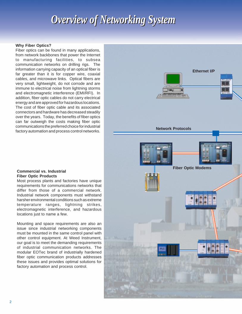
Why Fiber Optics?Fiber optics can be found in many applications,from network backbones that power the Internetto manufacturing facilit ies, to subseacommunication networks on drilling rigs. Theinformation carrying capacity of an optical fiber isfar greater than it is for copper wire, coaxialcables, and microwave links. Optical fibers arevery small, lightweight, do not corrode and areimmune to electrical noise from lightning stormsand electromagnetic interference (EMI/RFI). Inaddition, fiber optic cables do not carry electricalenergy and are approved for hazardous locations.The cost of fiber optic cable and its associatedconnectors and hardware has decreased steadilyover the years. Today, the benefits of fiber opticscan far outweigh the costs making fiber opticcommunications the preferred choice for industrialfactory automation and process control networks.
Ethernet I/P
Network Protocols
Fiber Optic Modems
3
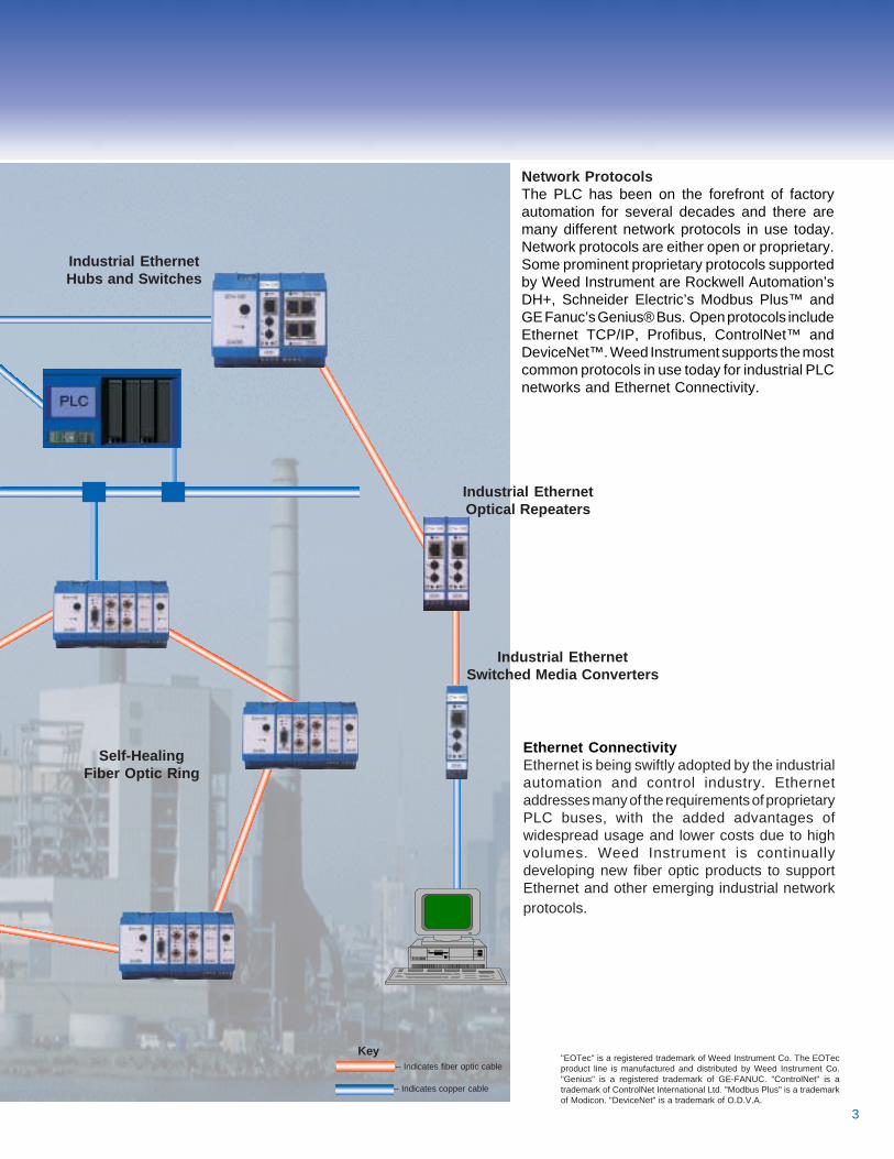
Network ProtocolsThe PLC has been on the forefront of factoryautomation for several decades and there aremany different network protocols in use today.Network protocols are either open or proprietary.Some prominent proprietary protocols supportedby Weed Instrument are Rockwell Automation’sDH+, Schneider Electric’s Modbus Plus™ andGE Fanuc’s Genius® Bus. Open protocols includeEthernet TCP/IP, Profibus, ControlNet™ andDeviceNet™. Weed Instrument supports the mostcommon protocols in use today for industrial PLCnetworks and Ethernet Connectivity.
Ethernet ConnectivityEthernet is being swiftly adopted by the industrialautomation and control industry. Ethernetaddresses many of the requirements of proprietaryPLC buses, with the added advantages ofwidespread usage and lower costs due to highvolumes. Weed Instrument is continuallydeveloping new fiber optic products to supportEthernet and other emerging industrial networkprotocols.
Industrial EthernetHubs and Switches
Industrial EthernetOptical Repeaters
Industrial EthernetSwitched Media Converters
Self-HealingFiber Optic Ring
-- Indicates fiber optic cable
-- Indicates copper cable
Key"EOTec" is a registered trademark of Weed Instrument Co. The EOTecproduct line is manufactured and distributed by Weed Instrument Co."Genius" is a registered trademark of GE-FANUC. "ControlNet" is atrademark of ControlNet International Ltd. "Modbus Plus" is a trademarkof Modicon. "DeviceNet" is a trademark of O.D.V.A.
4
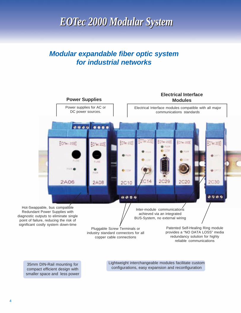
35mm DIN-Rail mounting forcompact efficient design withsmaller space and less power
EOTec 2000 Modular System
Lightweight interchangeable modules facilitate customconfigurations, easy expansion and reconfiguration
EOTec 2000 Modular System
Inter-module communicationsachieved via an integrated
BUS-System, no external wiring
Hot-Swappable, bus compatibleRedundant Power Supplies with
diagnostic outputs to eliminate singlepoint of failure, reducing the risk ofsignificant costly system down-time
Patented Self-Healing Ring moduleprovides a “NO DATA LOSS” media
redundancy solution for highlyreliable communications
Pluggable Screw Terminals orindustry standard connectors for all
copper cable connections
Power supplies for AC orDC power sources.
Power SuppliesElectrical Interface
ModulesElectrical Interface modules compatible with all major
communications standards
Modular expandable fiber optic systemfor industrial networks
5
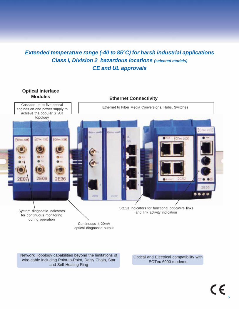
Network Topology capabilities beyond the limitations ofwire-cable including Point-to-Point, Daisy Chain, Star
and Self-Healing Ring
System diagnostic indicatorsfor continuous monitoring
during operation
Status indicators for functional optic/wire linksand link activity indication
Ethernet Connectivity
Ethernet to Fiber Media Conversions, Hubs, Switches
Optical and Electrical compatibility withEOTec 6000 modems
Cascade up to five opticalengines on one power supply to
achieve the popular STARtopology
Optical InterfaceModules
Extended temperature range (-40 to 85°C) for harsh industrial applicationsClass I, Division 2 hazardous locations (selected models)
CE and UL approvals
Continuous 4-20mAoptical diagnostic output
6
EOTec 2000 Fiber Optic ModemsEOTec 2000 Fiber Optic Modems
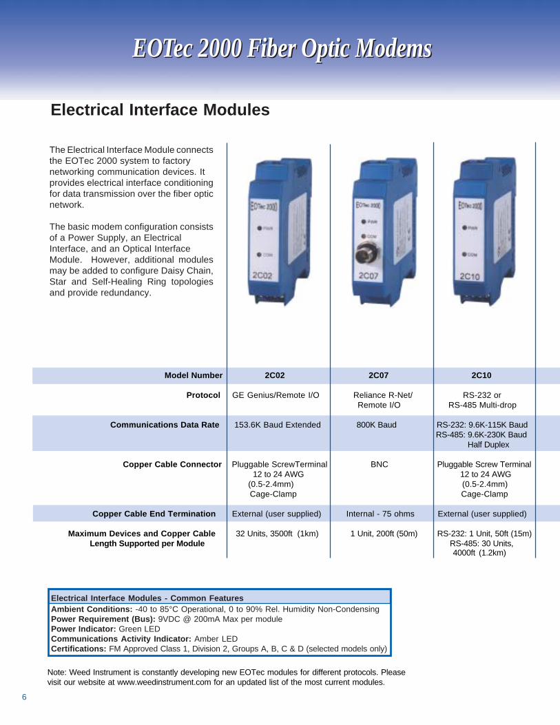
Model Number 2C02 2C07 2C10
Protocol GE Genius/Remote I/O Reliance R-Net/ RS-232 or Remote I/O RS-485 Multi-drop
Communications Data Rate 153.6K Baud Extended 800K Baud RS-232: 9.6K-115K Baud RS-485: 9.6K-230K Baud Half Duplex
Copper Cable Connector Pluggable ScrewTerminal BNC Pluggable Screw Terminal 12 to 24 AWG 12 to 24 AWG
(0.5-2.4mm) (0.5-2.4mm) Cage-Clamp Cage-Clamp
Copper Cable End Termination External (user supplied) Internal - 75 ohms External (user supplied)
Maximum Devices and Copper Cable 32 Units, 3500ft (1km) 1 Unit, 200ft (50m) RS-232: 1 Unit, 50ft (15m) Length Supported per Module RS-485: 30 Units,
The Electrical Interface Module connectsthe EOTec 2000 system to factorynetworking communication devices. Itprovides electrical interface conditioningfor data transmission over the fiber opticnetwork.
The basic modem configuration consistsof a Power Supply, an ElectricalInterface, and an Optical InterfaceModule. However, additional modulesmay be added to configure Daisy Chain,Star and Self-Healing Ring topologiesand provide redundancy.
Electrical Interface Modules - Common FeaturesAmbient Conditions: -40 to 85°C Operational, 0 to 90% Rel. Humidity Non-CondensingPower Requirement (Bus): 9VDC @ 200mA Max per modulePower Indicator: Green LEDCommunications Activity Indicator: Amber LEDCertifications: FM Approved Class 1, Division 2, Groups A, B, C & D (selected models only)
Electrical Interface Modules
4000ft (1.2km)
Note: Weed Instrument is constantly developing new EOTec modules for different protocols. Pleasevisit our website at www.weedinstrument.com for an updated list of the most current modules.
7
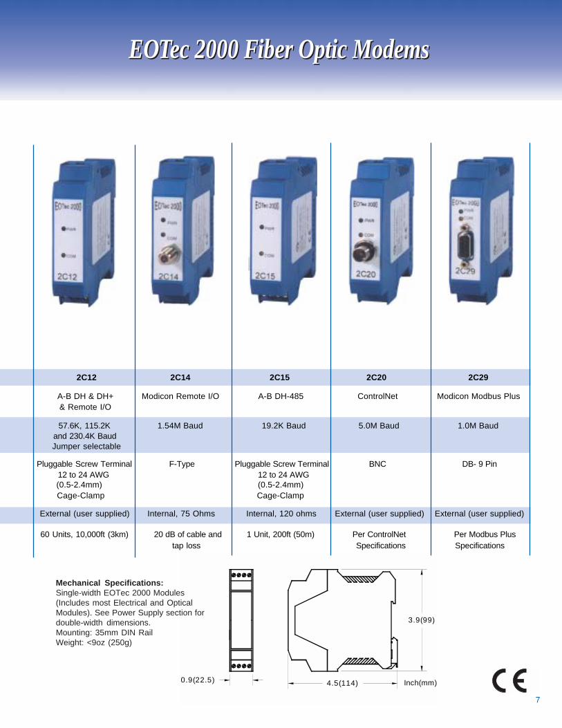
0.9(22.5) 4.5(114)
3.9(99)
Inch(mm)
EOTec 2000 Fiber Optic ModemsEOTec 2000 Fiber Optic Modems
Mechanical Specifications:Single-width EOTec 2000 Modules(Includes most Electrical and OpticalModules). See Power Supply section fordouble-width dimensions.Mounting: 35mm DIN RailWeight: <9oz (250g)
2C12 2C14 2C15 2C20 2C29
A-B DH & DH+ Modicon Remote I/O A-B DH-485 ControlNet Modicon Modbus Plus& Remote I/O
57.6K, 115.2K 1.54M Baud 19.2K Baud 5.0M Baud 1.0M Baudand 230.4K BaudJumper selectable
Pluggable Screw Terminal F-Type Pluggable Screw Terminal BNC DB- 9 Pin12 to 24 AWG 12 to 24 AWG(0.5-2.4mm) (0.5-2.4mm)Cage-Clamp Cage-Clamp
External (user supplied) Internal, 75 Ohms Internal, 120 ohms External (user supplied) External (user supplied)
60 Units, 10,000ft (3km) 20 dB of cable and 1 Unit, 200ft (50m) Per ControlNet Per Modbus Plustap loss Specifications Specifications
8
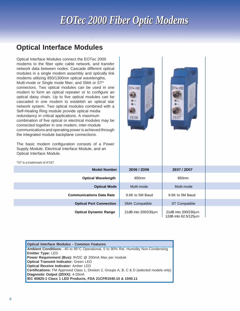
Optical Interface Modules connect the EOTec 2000modems to the fiber optic cable network, and transfernetwork data between nodes. Cascade different opticalmodules in a single modem assembly and optically linkmodems utilizing 850/1300nm optical wavelengths,Multi-mode or Single mode fiber, and SMA or ST*connectors. Two optical modules can be used in onemodem to form an optical repeater or to configure anoptical daisy chain. Up to five optical modules can becascaded in one modem to establish an optical starnetwork system. Two optical modules combined with aSelf-Healing Ring module provide optical mediaredundancy in critical applications. A maximumcombination of five optical or electrical modules may beconnected together in one modem, inter-modulecommunications and operating power is achieved throughthe integrated module backplane connections.
The basic modem configuration consists of a PowerSupply Module, Electrical Interface Module, and anOptical Interface Module.
*ST is a trademark of AT&T
Model Number 2E06 / 2D06 2E07 / 2D07
Optical Wavelength 850nm 850nm
Optical Mode Multi-mode Multi-mode
Communications Data Rate 9.6K to 5M Baud 9.6K to 5M Baud
Optical Port Connection SMA Compatible ST Compatible
Optical Dynamic Range 21dB into 200/230µm 21dB into 200/230µm 12dB into 62.5/125µm
Optical Interface Modules - Common FeaturesAmbient Conditions: -40 to 85°C Operational, 0 to 90% Rel. Humidity Non-CondensingEmitter Type: LEDPower Requirement (Bus): 9VDC @ 200mA Max per moduleOptical Transmit Indicator: Green LEDOptical Receive Indicator: Amber LEDCertifications: FM Approved Class 1, Division 2, Groups A, B, C & D (selected models only)Diagnostic Output (2DXX): 4-20mAIEC 60825-1 Class 1 LED Products, FDA 21CFR1040.10 & 1040.11
Optical Interface Modules
EOTec 2000 Fiber Optic ModemsEOTec 2000 Fiber Optic Modems
9
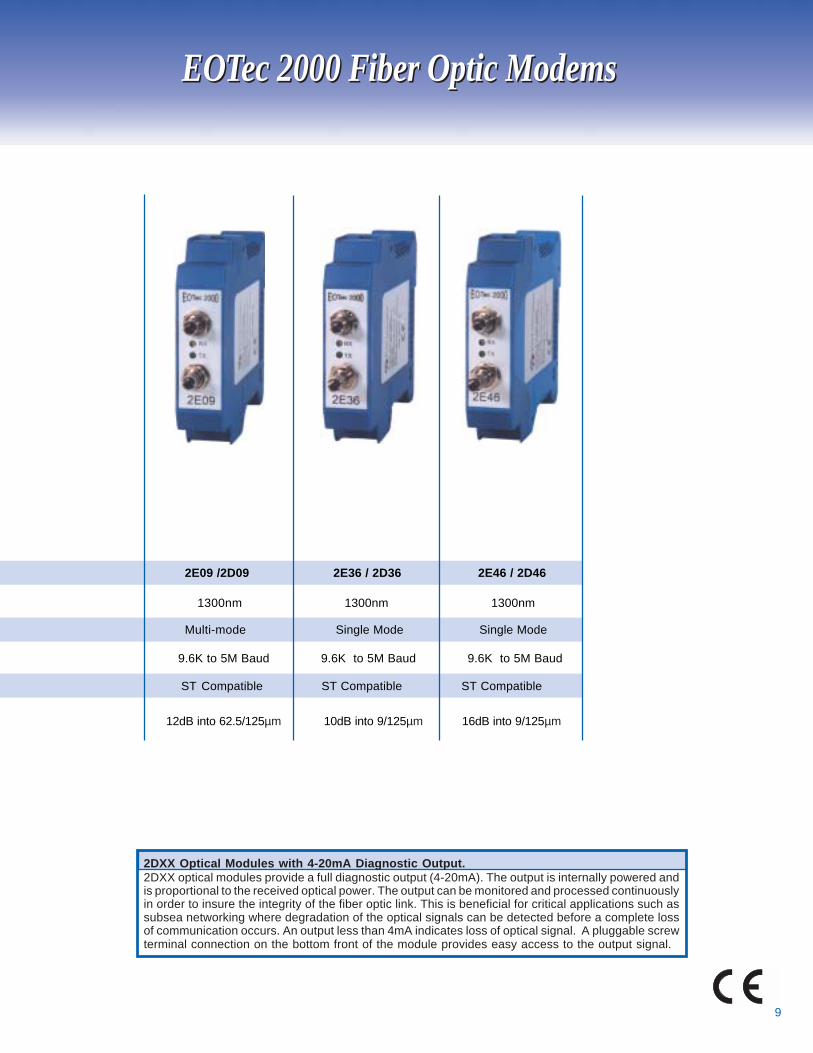
2DXX Optical Modules with 4-20mA Diagnostic Output.2DXX optical modules provide a full diagnostic output (4-20mA). The output is internally powered andis proportional to the received optical power. The output can be monitored and processed continuouslyin order to insure the integrity of the fiber optic link. This is beneficial for critical applications such assubsea networking where degradation of the optical signals can be detected before a complete lossof communication occurs. An output less than 4mA indicates loss of optical signal. A pluggable screwterminal connection on the bottom front of the module provides easy access to the output signal.
EOTec 2000 Fiber Optic ModemsEOTec 2000 Fiber Optic Modems
2E09 /2D09 2E36 / 2D36 2E46 / 2D46
1300nm 1300nm 1300nm
Multi-mode Single Mode Single Mode
9.6K to 5M Baud 9.6K to 5M Baud 9.6K to 5M Baud
ST Compatible ST Compatible ST Compatible
12dB into 62.5/125µm 10dB into 9/125µm 16dB into 9/125µm
10
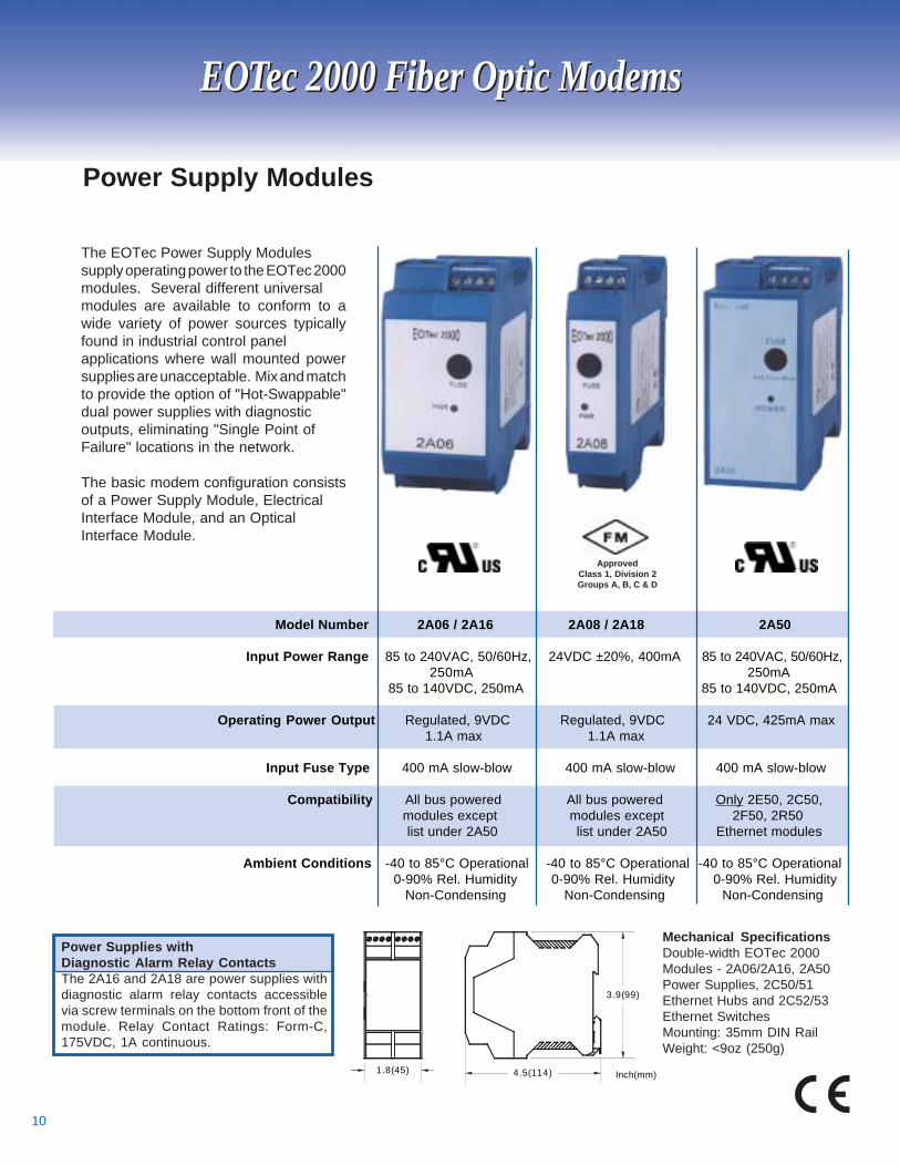
The EOTec Power Supply Modulessupply operating power to the EOTec 2000modules. Several different universalmodules are available to conform to awide variety of power sources typicallyfound in industrial control panelapplications where wall mounted powersupplies are unacceptable. Mix and matchto provide the option of "Hot-Swappable"dual power supplies with diagnosticoutputs, eliminating "Single Point ofFailure" locations in the network.
The basic modem configuration consistsof a Power Supply Module, ElectricalInterface Module, and an OpticalInterface Module.
Model Number 2A06 / 2A16 2A08 / 2A18 2A50
Input Power Range 85 to 240VAC, 50/60Hz, 24VDC ±20%, 400mA 85 to 240VAC, 50/60Hz,250mA 250mA
85 to 140VDC, 250mA 85 to 140VDC, 250mA
Operating Power Output Regulated, 9VDC Regulated, 9VDC 24 VDC, 425mA max 1.1A max 1.1A max
Input Fuse Type 400 mA slow-blow 400 mA slow-blow 400 mA slow-blow
Compatibility All bus powered All bus powered Only 2E50, 2C50, modules except modules except 2F50, 2R50 list under 2A50 list under 2A50 Ethernet modules
Ambient Conditions -40 to 85°C Operational -40 to 85°C Operational -40 to 85°C Operational 0-90% Rel. Humidity 0-90% Rel. Humidity 0-90% Rel. Humidity Non-Condensing Non-Condensing Non-Condensing
Power Supply Modules
Power Supplies withDiagnostic Alarm Relay ContactsThe 2A16 and 2A18 are power supplies withdiagnostic alarm relay contacts accessiblevia screw terminals on the bottom front of themodule. Relay Contact Ratings: Form-C,175VDC, 1A continuous.
EOTec 2000 Fiber Optic ModemsEOTec 2000 Fiber Optic Modems
1.8(45) 4.5(114)
3.9(99)
Inch(mm)
Mechanical SpecificationsDouble-width EOTec 2000Modules - 2A06/2A16, 2A50Power Supplies, 2C50/51Ethernet Hubs and 2C52/53Ethernet SwitchesMounting: 35mm DIN RailWeight: <9oz (250g)
ApprovedClass 1, Division 2Groups A, B, C & D

11
EOTec 2000 Fiber Optic ModemsEOTec 2000 Fiber Optic Modems
EOTec 2000 Power Supply Selection Chart
GE GeniusRemote I/O
Allen BradleyDH+ & Remote I/OModiconRemote I/OAllen BradleyDH-485
ModiconModbus Plus
Media Converter10 Base-TMedia Converter10 Base-TSwitched Media Converter10/100 Base-TSwitched Media Converter10/100 Base-TSwitched Media Converter10/100 Base-TSwitched Media Converter10/100 Base-TSwitched Media Converter10/100 Base-TSwitched Media Converter10/100 Base-TEthernet Hub10 Base-TEthernet Hub10 Base-TEthernet Switch10/100 MbpsEthernet Switch10/100 MbpsSHR - Hub10 Base-TSHR Media Converter10 Base-T
2C10 RS-232/485 X X
2C02 X X
2C12 X X
2C14 X X
2C15 X X
2C20 ControlNet X X
2C29 X X
2C30 Self-Healing Ring X X
2E50 X
2E51 X X
2E54 X X
2E55 X X X
2E56 X X
2E57 X X X
2E58 X X
2E59 X X X
2C50 X
2C51 X
2C52 X X
2C53 X X X
2R50 X X
2A50Model# Module Description 2A06/ 2A08/ External 2A16 2A18 24VDC
Reliance R-Net Remote I/O2C07 X X
2E06/2D06 Optical Module
2E07/2D07 Optical Module X X
2E09/2D09 Optical Module X X
2E36/2D36 Optical Module X X
2E46/2D46 Optical Module X X
X X
2F50 Power Supply via 2R50
DH,
12
EOTec 2000 Network TopologiesEOTec 2000 Network Topologies
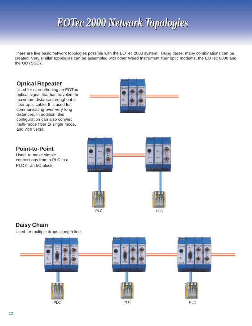
There are five basic network topologies possible with the EOTec 2000 system. Using these, many combinations can becreated. Very similar topologies can be assembled with other Weed Instrument fiber optic modems, the EOTec 6000 andthe ODYSSEY.
Point-to-PointUsed to make simpleconnections from a PLC to aPLC or an I/O block.
Daisy ChainUsed for multiple drops along a line.
Optical RepeaterUsed for strengthening an EOTecoptical signal that has traveled themaximum distance throughout afiber optic cable. It is used forcommunicating over very longdistances. In addition, thisconfiguration can also convertmulti-mode fiber to single mode,and vice versa.
PLC PLC
PLCPLCPLC
13
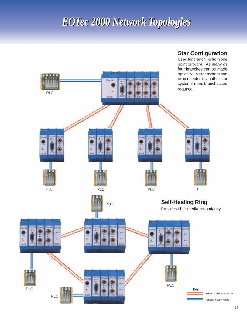
Star ConfigurationUsed for branching from onepoint outward. As many asfour branches can be madeoptically. A star system canbe connected to another starsystem if more branches arerequired.
Self-Healing RingProvides fiber media redundancy.
EOTec 2000 Network TopologiesEOTec 2000 Network Topologies
-- Indicates fiber optic cable
-- Indicates copper cable
KeyPLC
PLC
PLCPLCPLCPLC
PLC
PLC
PLC
14
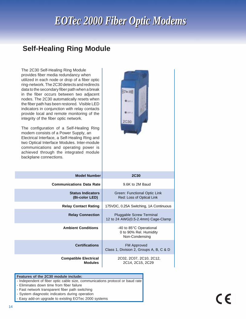
The 2C30 Self-Healing Ring Moduleprovides fiber media redundancy whenutilized in each node or drop of a fiber opticring-network. The 2C30 detects and redirectsdata to the secondary fiber path when a breakin the fiber occurs between two adjacentnodes. The 2C30 automatically resets whenthe fiber path has been restored. Visible LEDindicators in conjunction with relay contactsprovide local and remote monitoring of theintegrity of the fiber optic network.
The configuration of a Self-Healing Ringmodem consists of a Power Supply, anElectrical Interface, a Self-Healing Ring andtwo Optical Interface Modules. Inter-modulecommunications and operating power isachieved through the integrated modulebackplane connections.
Model Number 2C30
Communications Data Rate 9.6K to 2M Baud
Status Indicators Green: Functional Optic Link (Bi-color LED) Red: Loss of Optical Link
Relay Contact Rating 175VDC, 0.25A Switching, 1A Continuous
Relay Connection Pluggable Screw Terminal 12 to 24 AWG(0.5-2.4mm) Cage-Clamp
Ambient Conditions -40 to 85°C Operational 0 to 90% Rel. Humidity
Non-Condensing
Certifications FM Approved Class 1, Division 2, Groups A, B, C & D
Compatible Electrical 2C02, 2C07, 2C10, 2C12, Modules 2C14, 2C15, 2C29
Self-Healing Ring Module
Features of the 2C30 module include:- Independent of fiber optic cable size, communications protocol or baud rate- Eliminates down time from fiber failure- Fast network transparent fiber path switching- System diagnostic indicators during operation- Easy add-on upgrade to existing EOTec 2000 systems
EOTec 2000 Fiber Optic ModemsEOTec 2000 Fiber Optic Modems
15
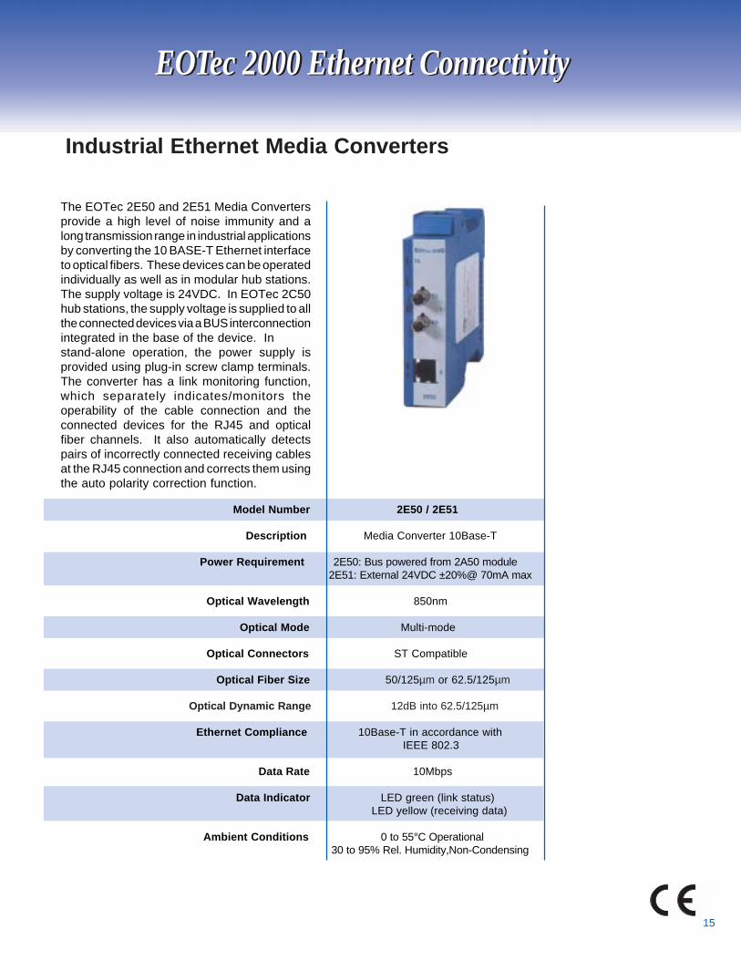
The EOTec 2E50 and 2E51 Media Convertersprovide a high level of noise immunity and along transmission range in industrial applicationsby converting the 10 BASE-T Ethernet interfaceto optical fibers. These devices can be operatedindividually as well as in modular hub stations.The supply voltage is 24VDC. In EOTec 2C50hub stations, the supply voltage is supplied to allthe connected devices via a BUS interconnectionintegrated in the base of the device. Instand-alone operation, the power supply isprovided using plug-in screw clamp terminals.The converter has a link monitoring function,which separately indicates/monitors theoperability of the cable connection and theconnected devices for the RJ45 and opticalfiber channels. It also automatically detectspairs of incorrectly connected receiving cablesat the RJ45 connection and corrects them usingthe auto polarity correction function.
Model Number 2E50 / 2E51
Description Media Converter 10Base-T
Power Requirement 2E50: Bus powered from 2A50 module 2E51: External 24VDC ±20%@ 70mA max
Optical Wavelength 850nm
Optical Mode Multi-mode
Optical Connectors ST Compatible
Optical Fiber Size 50/125µm or 62.5/125µm
Optical Dynamic Range 12dB into 62.5/125µm
Ethernet Compliance 10Base-T in accordance with IEEE 802.3
Data Rate 10Mbps
Data Indicator LED green (link status) LED yellow (receiving data)
Ambient Conditions 0 to 55°C Operational 30 to 95% Rel. Humidity,Non-Condensing
Industrial Ethernet Media Converters
EOTec 2000 Ethernet ConnectivityEOTec 2000 Ethernet Connectivity
16
Model Number 2E54 / 2E55 2E56 / 2E57 2E58 / 2E59 2E60/2E61
Description Switched Media Switched Media Switched Media Switched Media Converter Converter Converter Converter
10/100Mbps 10/100Mbps 10/100Mbps 10/100Mbps
Power Requirement 2E54: Bus powered 2E56: Bus powered 2E58: Bus powered 2E60: Bus powered from 2A06 or 2A08 from2A06 or 2A08 from 2A06 or 2A08 from2A06 or 2A08 2E55: External, 2E57: External, 2E59: External 2E61: External
10-30VDC@200mA 10-30VDC@200mA 1 0-30VDC@200mA 1 0-30VDC@200mA
Optical Data Rate 100Mbps, Full duplex 100Mbps, Full duplex 100Mbps, Full duplex 100Mbps, Full duplex
Optical Wavelength 1300nm 1300nm 1300nm 1300nm
Optical Mode Multi-mode Multi-mode Single mode Single mode
Optical Connectors ST Compatible SC Compatible SC Compatible SC Compatible
Optical Fiber Size 50 - 100µm core diameter 50 - 100µm core diameter 5 - 10µm core diameter 5-10µm core diameter
Optical Dynamic Range 9dB 9dB 16dB 36dB
EOTec 2000 Ethernet Connectivity
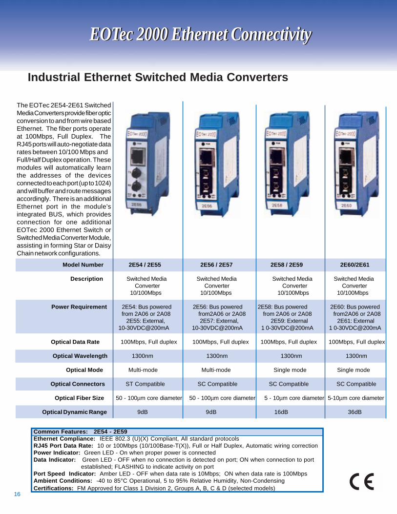
The EOTec 2E54-2E61 SwitchedMedia Converters provide fiber opticconversion to and from wire basedEthernet. The fiber ports operateat 100Mbps, Full Duplex. TheRJ45 ports will auto-negotiate datarates between 10/100 Mbps andFull/Half Duplex operation. Thesemodules will automatically learnthe addresses of the devicesconnected to each port (up to 1024)and will buffer and route messagesaccordingly. There is an additionalEthernet port in the module'sintegrated BUS, which providesconnection for one additionalEOTec 2000 Ethernet Switch orSwitched Media Converter Module,assisting in forming Star or DaisyChain network configurations.
Industrial Ethernet Switched Media Converters
EOTec 2000 Ethernet Connectivity
Common Features: 2E54 - 2E59Ethernet Compliance: IEEE 802.3 (U)(X) Compliant, All standard protocolsRJ45 Port Data Rate: 10 or 100Mbps (10/100Base-T(X)), Full or Half Duplex, Automatic wiring correctionPower Indicator: Green LED - On when proper power is connectedData Indicator: Green LED - OFF when no connection is detected on port; ON when connection to port established; FLASHING to indicate activity on portPort Speed Indicator: Amber LED - OFF when data rate is 10Mbps; ON when data rate is 100MbpsAmbient Conditions: -40 to 85°C Operational, 5 to 95% Relative Humidity, Non-CondensingCertifications: FM Approved for Class 1 Division 2, Groups A, B, C & D (selected models)
17
Model Number 2C50 / 2C51 2C52 / 2C53
Description Ethernet Hub Ethernet Switch 4 RJ45 ports 4 RJ45 ports 1 bus port
Power Requirements 2C50: Bus powered from 2A50 2C52: Bus powered from 2A06/16 or 2A08/18
2C51: External 19-30VDC @ 180mA 2C53: External 10-30VDC @180mA
Communications Data 10 Base-T 10/100 Base-T Half Duplex Full or Half Duplex
Ethernet Compliance IEEE 802.3 Compliant, IEEE 802.3 (U)(X) Compliant, All standard protocols All standard protocols
Port Activity Indicators Red: message collision Green LED: Off when no connection Green: link activity is detected on port, On when Yellow: receiving message connection to port established, Flashing to indicate activity on port
Port Speed (RJ45) Indicator None Amber LED: Off when data rate is 10Mbps, On when data
rate is 100Mbps
Ambient Conditions 0 to 55°C Operational -40 to 85°C Operational 30 to 95% RH, Non-Condensing 5 to 95% RH, Non-Condensing
Industrial Ethernet Hubs and Switches
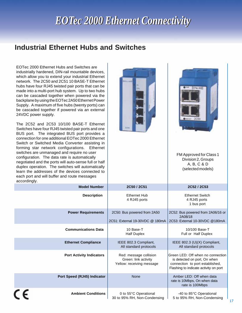
EOTec 2000 Ethernet Hubs and Switches areindustrially hardened, DIN-rail mountable devices,which allow you to extend your industrial Ethernetnetwork. The 2C50 and 2C51 10 BASE-T Ethernethubs have four RJ45 twisted pair ports that can bemade into a multi-port hub system. Up to two hubscan be cascaded together when powered via thebackplane by using the EOTec 2A50 Ethernet PowerSupply. A maximum of five hubs (twenty ports) canbe cascaded together if powered via an external24VDC power supply.
The 2C52 and 2C53 10/100 BASE-T EthernetSwitches have four RJ45 twisted pair ports and oneBUS port. The integrated BUS port provides aconnection for one additional EOTec 2000 EthernetSwitch or Switched Media Converter assisting informing star network configurations. Ethernetswitches are unmanaged and require no userconfiguration. The data rate is automaticallynegotiated and the ports will auto-sense full or halfduplex operation. The switches will automaticallylearn the addresses of the devices connected toeach port and will buffer and route messagesaccordingly.
EOTec 2000 Ethernet ConnectivityEOTec 2000 Ethernet Connectivity
FM Approved for Class 1Division 2, Groups
A, B, C & D(selected models)

18
By using two EOTec 2F50 Media Converters and one2R50 Ethernet Hub configured in one modular assembly,a 10 Base-T Industrial Ethernet network can be configuredin a ring providing optical redundancy and a high level ofnoise immunity for long distance transmissions over fiberoptic cable. Connecting the optical fiber ports together toform a redundant self-healing ring allows forcommunications between any two nodes to be maintainedeven when a break in the fiber optic link occurs. Visiblefault indicators, and potential-free diagnostic alarm relayoutputs, are provided to locate fiber fault conditions.
External copper connections are required betweenmodules, leaving two RJ45 ports available for connectionto end devices. Power can be supplied through thebackplane using the 2A50 power supply or externallythrough a terminal block on any one of the three modules.
Model Numbers 2F50(2) and 2R50
Description Ethernet Self-Healing Ring Assembly
Power Requirement Bus powered by 2A50 module, and/or external 24 VDC ± 20% @ 320mA
Optical Wavelength 850nm
Optical Mode Multi-mode
Optical Connectors ST Compatible
Optical Fiber Size 50/125µm or 62.5/125µm
Optical Dynamic Range 12dB into 62.5/125µm
Communications Data Rate 10 Base-T, Half Duplex
Ethernet Compliance IEEE 802.3 Compliant, all standard protocols
Status Indicators All standard Ethernet status indicators Bi-color LED for optical fiber status
Relay Contact Rating 175VDC, 0.25A Switching, 1A Continuous
Relay Connection Pluggable screw terminal 12 - 24 AWG (0.5-2.4mm) Cage-Clamp
Ambient Conditions 0 to 55°C Operational 30 to 95% Rel. Humidity, Non-Condensing
Industrial Ethernet Self-Healing Ring Assembly
EOTec 2000 Ethernet ConnectivityEOTec 2000 Ethernet Connectivity
19
EOTec 2000 Ethernet ConnectivityEOTec 2000 Ethernet Connectivity
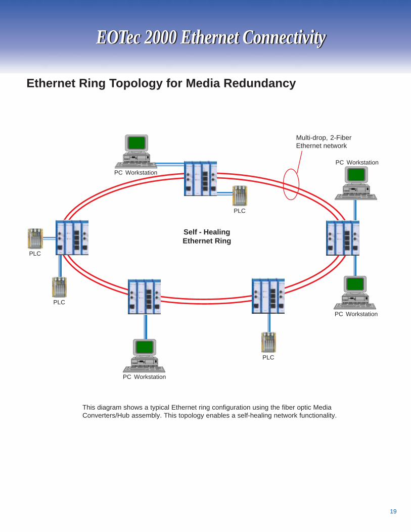
Ethernet Ring Topology for Media Redundancy
Multi-drop, 2-FiberEthernet network
PC Workstation
PC Workstation
This diagram shows a typical Ethernet ring configuration using the fiber optic MediaConverters/Hub assembly. This topology enables a self-healing network functionality.
Self - HealingEthernet Ring
PLC
PLC
PLC
PLC
PC Workstation
PC Workstation
20
EOTec 6000 Fiber Optic Modems
PLC Compatibility:
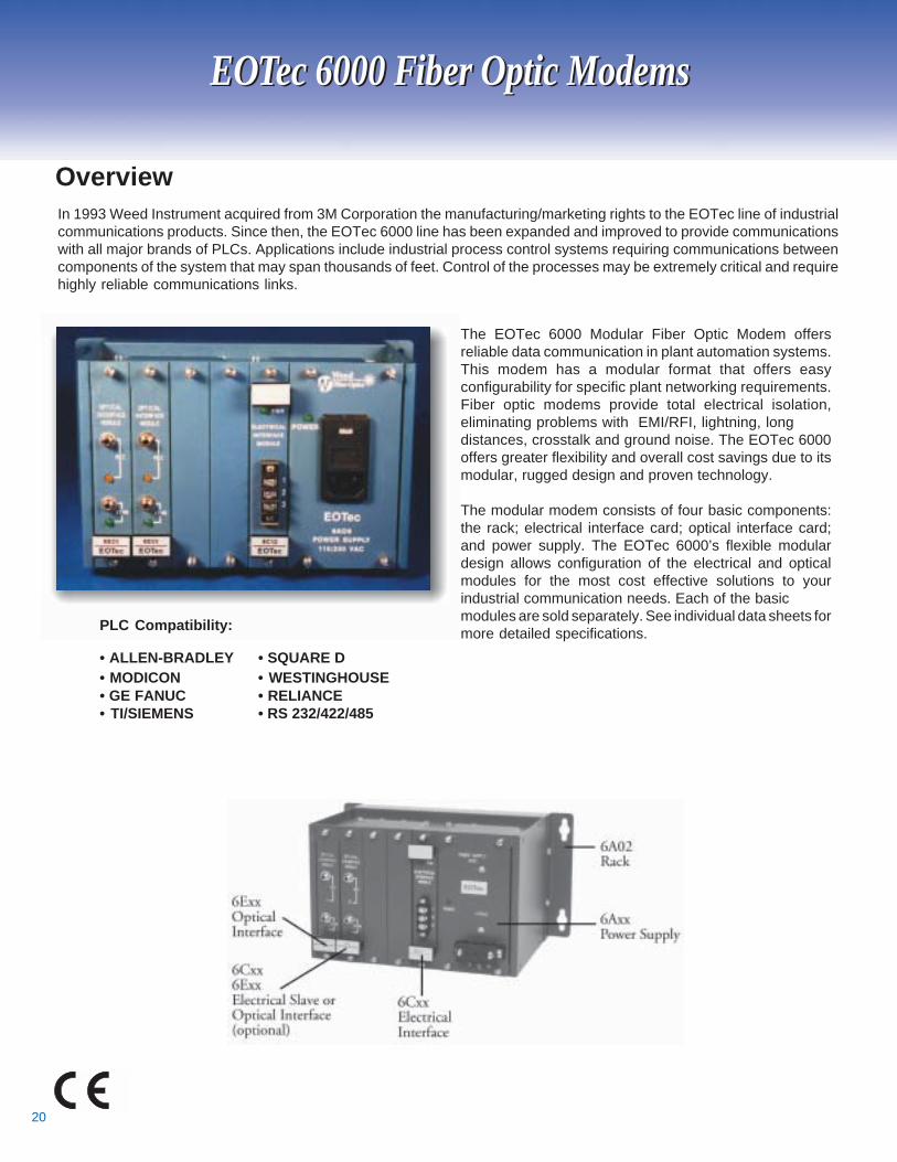
• ALLEN-BRADLEY • SQUARE D• MODICON • WESTINGHOUSE• GE FANUC • RELIANCE• TI/SIEMENS • RS 232/422/485
The EOTec 6000 Modular Fiber Optic Modem offersreliable data communication in plant automation systems.This modem has a modular format that offers easyconfigurability for specific plant networking requirements.Fiber optic modems provide total electrical isolation,eliminating problems with EMI/RFI, lightning, longdistances, crosstalk and ground noise. The EOTec 6000offers greater flexibility and overall cost savings due to itsmodular, rugged design and proven technology.
The modular modem consists of four basic components:the rack; electrical interface card; optical interface card;and power supply. The EOTec 6000’s flexible modulardesign allows configuration of the electrical and opticalmodules for the most cost effective solutions to yourindustrial communication needs. Each of the basicmodules are sold separately. See individual data sheets formore detailed specifications.
EOTec 6000 Fiber Optic Modems
OverviewIn 1993 Weed Instrument acquired from 3M Corporation the manufacturing/marketing rights to the EOTec line of industrialcommunications products. Since then, the EOTec 6000 line has been expanded and improved to provide communicationswith all major brands of PLCs. Applications include industrial process control systems requiring communications betweencomponents of the system that may span thousands of feet. Control of the processes may be extremely critical and requirehighly reliable communications links.
21
6A01 - Power Supply (115 VAC input)
6A02 - Modular Rack
6A03 - Power Supply (220 VAC input)
6A04 - Blank panel for unpopulated rack slots
6A05 - Power Supply (90 to 165 VDC input)
6A06 - Power Supply (110/220 VAC input) UL Approved
6A08 - Power Supply (24 VDC)
6A09 - Heavy duty bracket
6A10 - Bracket for 19" Rack Mount
6A18 - Redundant Power Supply (24 VDC input)
6A28 - Dual 6A18 Housing
Power Supplies/Racks
“SY/NET” is a trademark of Square D. “TI Tiway” is a trademark of Texas Instruments.“Westinghouse HPPC” is a trademark of Westinghouse. “Reliance R-Net” is a trademark ofReliance Electric Company.*
Module # - Description
Module # - Description6C01 - Modicon Remote I/O Compatible, BNC connector
6C02 - GE Fanuc Genius™ I/O Compatible
6C03 - Square D SY/NET™ Compatible
6C04 - Westinghouse HPPC™ Compatible
6C05 - TI Tiway™ Compatible
6C06 - TI 560/565 I/O Compatible
6C07 - Reliance R-Net™ & I/O Compatible
6C09 - Modicon ModbusPlus™
6C10 - RS 232/422 Compatible
6C11 - Modicon Remote I/O Self-Healing Ring Module
6C12 - Allen Bradley DH+ and I/O Compatible
6C14 - Modicon Remote I/O Compatible, F connector
6C15 - Allen Bradley DH-485 Compatible
6C16 - RS-485, DB-9 Connector
6C17 - RS-485, F Connector
6C29 - Modicon Modbus Plus™ Compatible ModConnect® certified
6C30 - Self-Healing Ring Master Module
6C31 - Self-Healing Ring Slave Module
5
Electrical Interfaces
EOTec 6000 Fiber Optic ModemsEOTec 6000 Fiber Optic Modems
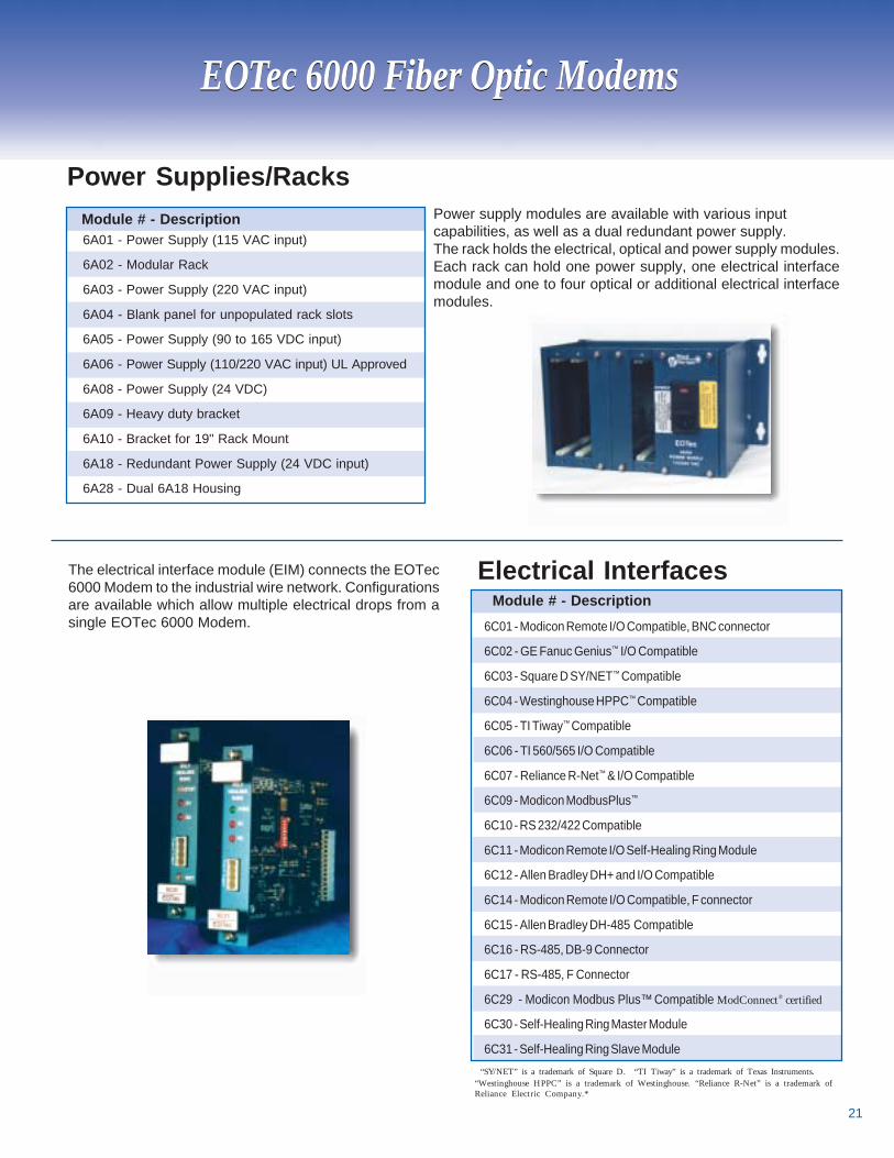
The electrical interface module (EIM) connects the EOTec6000 Modem to the industrial wire network. Configurationsare available which allow multiple electrical drops from asingle EOTec 6000 Modem.
Power supply modules are available with various inputcapabilities, as well as a dual redundant power supply.The rack holds the electrical, optical and power supply modules.Each rack can hold one power supply, one electrical interfacemodule and one to four optical or additional electrical interfacemodules.
22
6E01 SMA 850nm Multi-mode 9.6K-500K 17dB N/A N/A
6E02 SMA 850nm Multi-mode 9.6K-500K 23dB N/A N/A
6E03 ST 850nm Multi-mode 9.6K-500K 17dB 12dB N/A
6E04 ST 850nm Multi-mode 9.6K-500K 23dB 17dB N/A
6E05 ST 1300nm Multi-mode 9.6K-500K N/A 12dB N/A
6E06 SMA 850nm Multi-mode 500K-2M 17dB N/A N/A
6E07 ST 850nm Multi-mode 500K-2M 17dB 12dB N/A
6E08 SMA 850nm Multi-mode 500K-2M 23dB N/A N/A
6E09 ST 1300nm Multi-mode 500K-2M N/A 12dB N/A
6E10 ST 850nm Multi-mode 500K-2M 23dB 17dB N/A
6E21 ST 850nm Multi-mode 9.6K-2M N/A 5dB N/A
6E31 ST 1300nm Single Mode 9.6K-500K N/A N/A 10dB
6E36 ST 1300nm Single Mode 500K-2M N/A N/A 10dB
6E41 ST 1300nm Single Mode 9.6K-500K N/A N/A 16dB
6E46 ST 1300nm Single Mode 500K-2M N/A N/A 16dB
OpticalModule
OpticalConnectivity
Wavelength OpticalMode Baud Rate
Optical DynamicRange
200/230 µm
Optical DynamicRange
62.5/125µm
Optical DynamicRange
9/125µm
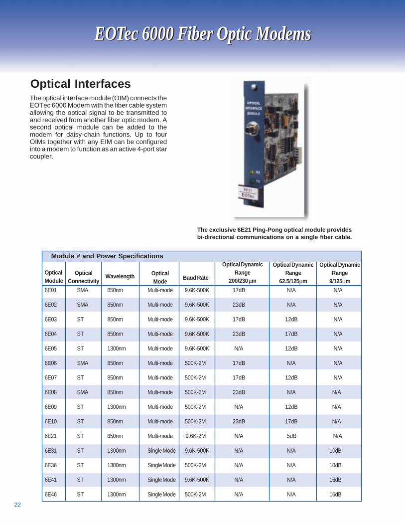
Optical InterfacesThe optical interface module (OIM) connects theEOTec 6000 Modem with the fiber cable systemallowing the optical signal to be transmitted toand received from another fiber optic modem. Asecond optical module can be added to themodem for daisy-chain functions. Up to fourOIMs together with any EIM can be configuredinto a modem to function as an active 4-port starcoupler.
Module # and Power Specifications
EOTec 6000 Fiber Optic ModemsEOTec 6000 Fiber Optic Modems
The exclusive 6E21 Ping-Pong optical module providesbi-directional communications on a single fiber cable.
23
6E01
6E02
6E03
6E04
6E05
6E06
6E07
6E08
6E09
6E10
6E21
6E31
6E41
6E36
6E46
6C01 Modicon Remote I/O BNC Connector X X X X X X X X
6C02 GE Fanuc Genius I/O X X X X X X X
6C03 Square D SY/NET X X X X X X X
6C04 Westinghouse HPPC X X X X X X X X
6C05 TI T iway X X X X X X X
6C06 TI 560/565 I/O X X X X X X X X
6C07 Reliance R-Net & I/O X X X X X X X X
6C09 Modicon Modbus Plus X X X X X X X X
6C10 RS 232/422 X X X X X X X
6C12 Allen Bradley DH+ & Remote I/O X X X X X X X
6C14 Modicon Remote I/O F Connector X X X X X X X X
6C15 Allen Bradley SLC 500 X X X X X X X
6C16 RS 485 DB-9 Connector X X X X X X X
6C17 RS 485 F-Connector X X X X X X X X
6C29 Modicon Modbus Plus X X X X X X X X
Multi-Mode Single Mode
9.6K-500K Baud 500K-2M Baud 9.6K-500K 500K-2M
EOTec 6000 Fiber Optic ModemsEOTec 6000 Fiber Optic Modems
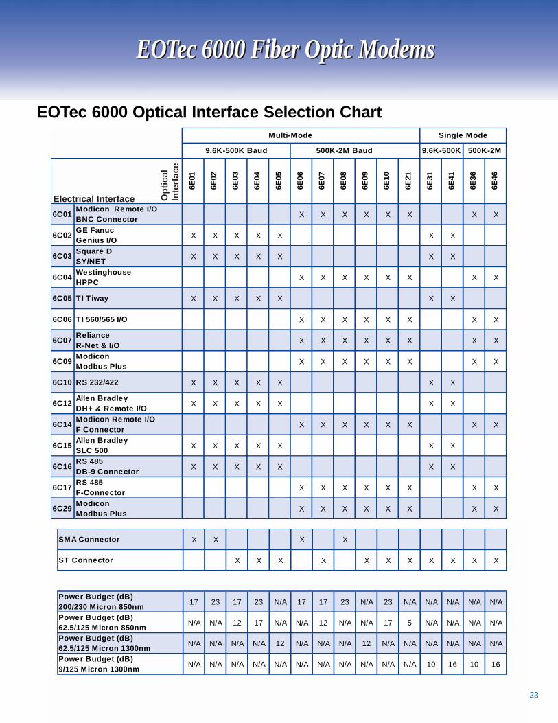
EOTec 6000 Optical Interface Selection Chart
Opt
ical
Inte
rfac
e
Electrical Interface
SMA Connector X X X X
ST Connector X X X X X X X X X X X
Power Budget (dB) 200/230 Micron 850nm 17 23 17 23 N/A 17 17 23 N/A 23 N/A N/A N/A N/A N/A
Power Budget (dB) 62.5/125 Micron 850nm N/A N/A 12 17 N/A N/A 12 N/A N/A 17 5 N/A N/A N/A N/A
Power Budget (dB) 62.5/125 Micron 1300nm N/A N/A N/A N/A 12 N/A N/A N/A 12 N/A N/A N/A N/A N/A N/A
Power Budget (dB) 9/125 Micron 1300nm N/A N/A N/A N/A N/A N/A N/A N/A N/A N/A N/A 10 16 10 16
24
ODYSSEY Fiber Optic Modemfor Allen-Bradley PLC, In-Rack Mount
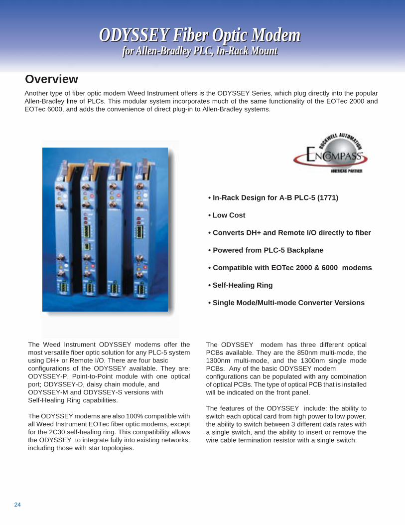
The Weed Instrument ODYSSEY modems offer themost versatile fiber optic solution for any PLC-5 systemusing DH+ or Remote I/O. There are four basicconfigurations of the ODYSSEY available. They are:ODYSSEY-P, Point-to-Point module with one opticalport; ODYSSEY-D, daisy chain module, andODYSSEY-M and ODYSSEY-S versions withSelf-Healing Ring capabilities.
The ODYSSEY modems are also 100% compatible withall Weed Instrument EOTec fiber optic modems, exceptfor the 2C30 self-healing ring. This compatibility allowsthe ODYSSEY to integrate fully into existing networks,including those with star topologies.
ODYSSEY Fiber Optic Modemfor Allen-Bradley PLC, In-Rack Mount
• In-Rack Design for A-B PLC-5 (1771)
• Low Cost
• Converts DH+ and Remote I/O directly to fiber
• Powered from PLC-5 Backplane
• Compatible with EOTec 2000 & 6000 modems
• Self-Healing Ring
• Single Mode/Multi-mode Converter Versions
Another type of fiber optic modem Weed Instrument offers is the ODYSSEY Series, which plug directly into the popularAllen-Bradley line of PLCs. This modular system incorporates much of the same functionality of the EOTec 2000 andEOTec 6000, and adds the convenience of direct plug-in to Allen-Bradley systems.
6
Overview
The ODYSSEY modem has three different opticalPCBs available. They are the 850nm multi-mode, the1300nm multi-mode, and the 1300nm single modePCBs. Any of the basic ODYSSEY modemconfigurations can be populated with any combinationof optical PCBs. The type of optical PCB that is installedwill be indicated on the front panel.
The features of the ODYSSEY include: the ability toswitch each optical card from high power to low power,the ability to switch between 3 different data rates witha single switch, and the ability to insert or remove thewire cable termination resistor with a single switch.
25
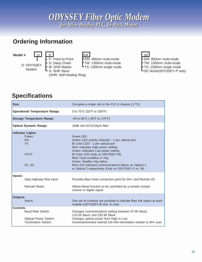
Size: Occupies a single slot in the PLC-5 chassis (1771)
Operational Temperature Range: 0 to 70°C (32°F to 158°F)
Storage Temperature Range: -40 to 80°C (-40°F to 176°F)
Optical Dynamic Range: 16dB into 62.5/125µm fiber
Indicator Lights:Power: Green LEDRX: Amber LED activity indicator - 1 per optical portTX Bi Color LED - 1 per optical port
Red: Indicates High power settingGreen: Indicates Low power setting
STAT: Bi Color LED (only on ODYSSEY-M)Red: Fault condition in ringGreen: Healthy ring status
S1, S2: Red LED indicates communications failure on Optical 1or Optical 2 respectively (Only on ODYSSEY-S or -M)
Inputs:Data Highway Plus input: Provides Blue Hose connection point for DH+ and Remote I/O
Remote Reset: Allows Reset function to be controlled by a remote contactclosure or digital signal
Outputs:Alarm: One set of contacts are provided to indicate fiber link status at each
module (ODYSSEY-M and -S only)Controls:
Baud Rate Switch: Changes communications setting between 57.6K Baud,115.2K Baud, and 230.4K Baud
Optical Power Switch: Changes optical power from High to LowTermination Switch: Connects/removes internal 120 ohm termination resistor to DH+ port.
Model # O P EM 00P: Point-to-Point EM: 850nm multi-mode EM: 850nm multi-modeD: Daisy Chain TM: 1300nm multi-mode TM: 1300nm multi-modeM: SHR Master TS: 1300nm single mode TS: 1300nm single modeS: SHR Slave 00: None(ODYSSEY-P only)(SHR: Self-Healing Ring)
O: ODYSSEY Modem
Ordering Information
7
Specifications
ODYSSEY Fiber Optic Modemfor Allen-Bradley PLC, In-Rack Mount
ODYSSEY Fiber Optic Modemfor Allen-Bradley PLC, In-Rack Mount
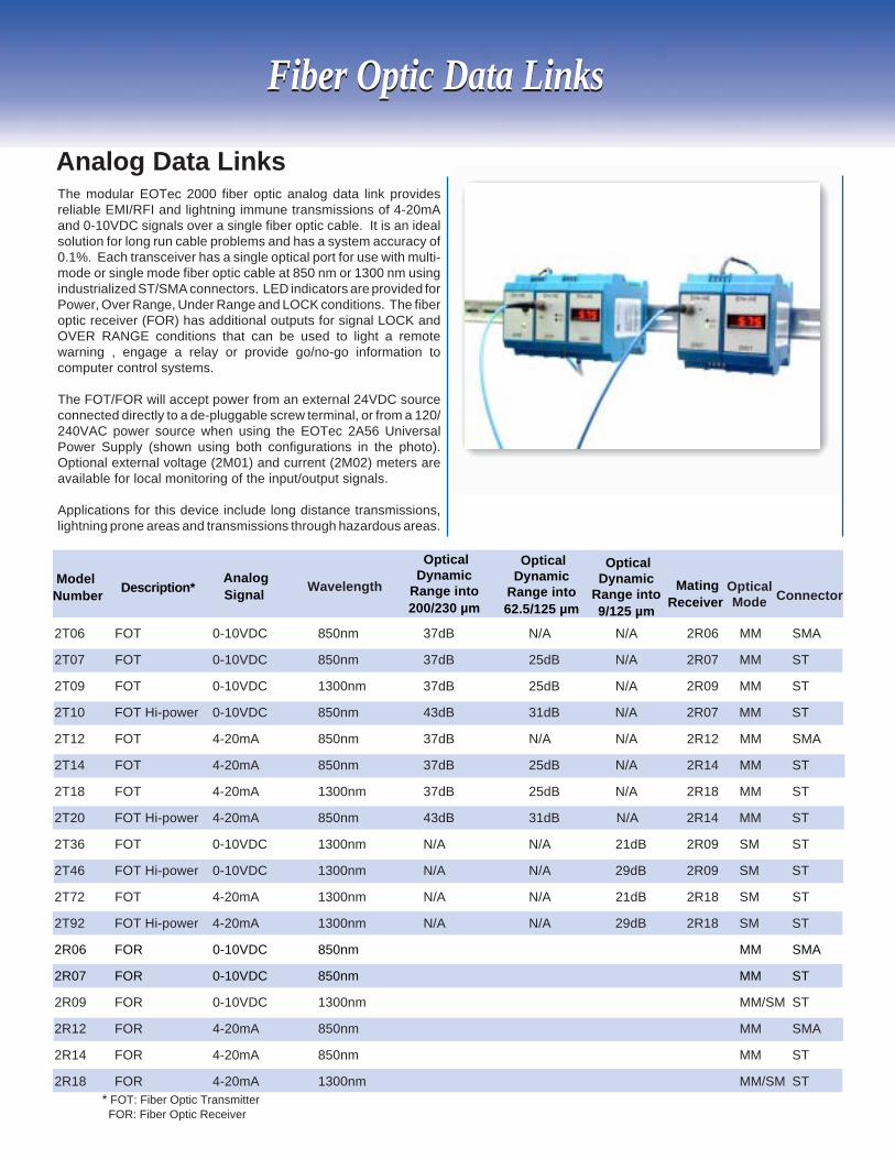
The modular EOTec 2000 fiber optic analog data link providesreliable EMI/RFI and lightning immune transmissions of 4-20mAand 0-10VDC signals over a single fiber optic cable. It is an idealsolution for long run cable problems and has a system accuracy of0.1%. Each transceiver has a single optical port for use with multi-mode or single mode fiber optic cable at 850 nm or 1300 nm usingindustrialized ST/SMA connectors. LED indicators are provided forPower, Over Range, Under Range and LOCK conditions. The fiberoptic receiver (FOR) has additional outputs for signal LOCK andOVER RANGE conditions that can be used to light a remotewarning , engage a relay or provide go/no-go information tocomputer control systems.
The FOT/FOR will accept power from an external 24VDC sourceconnected directly to a de-pluggable screw terminal, or from a 120/240VAC power source when using the EOTec 2A56 UniversalPower Supply (shown using both configurations in the photo).Optional external voltage (2M01) and current (2M02) meters areavailable for local monitoring of the input/output signals.
Applications for this device include long distance transmissions,lightning prone areas and transmissions through hazardous areas.
Analog Data Links
Fiber Optic Data LinksFiber Optic Data Links
ModelNumber Wavelength Optical
Mode
2T06 FOT 0-10VDC 850nm 37dB N/A N/A 2R06 MM SMA
2T07 FOT 0-10VDC 850nm 37dB 25dB N/A 2R07 MM ST
2T09 FOT 0-10VDC 1300nm 37dB 25dB N/A 2R09 MM ST
2T10 FOT Hi-power 0-10VDC 850nm 43dB 31dB N/A 2R07 MM ST
2T12 FOT 4-20mA 850nm 37dB N/A N/A 2R12 MM SMA
2T14 FOT 4-20mA 850nm 37dB 25dB N/A 2R14 MM ST
2T18 FOT 4-20mA 1300nm 37dB 25dB N/A 2R18 MM ST
2T20 FOT Hi-power 4-20mA 850nm 43dB 31dB N/A 2R14 MM ST
2T36 FOT 0-10VDC 1300nm N/A N/A 21dB 2R09 SM ST
2T46 FOT Hi-power 0-10VDC 1300nm N/A N/A 29dB 2R09 SM ST
2T72 FOT 4-20mA 1300nm N/A N/A 21dB 2R18 SM ST
2T92 FOT Hi-power 4-20mA 1300nm N/A N/A 29dB 2R18 SM ST
2R06 FOR 0-10VDC 850nm MM SMA
2R07 FOR 0-10VDC 850nm MM ST
2R09 FOR 0-10VDC 1300nm MM/SM ST
2R12 FOR 4-20mA 850nm MM SMA
2R14 FOR 4-20mA 850nm MM ST
2R18 FOR 4-20mA 1300nm MM/SM ST
Description* AnalogSignal Connector
* FOT: Fiber Optic Transmitter FOR: Fiber Optic Receiver
OpticalDynamic
Range into200/230 µm
OpticalDynamic
Range into62.5/125 µm
MatingReceiver
OpticalDynamic
Range into9/125 µm
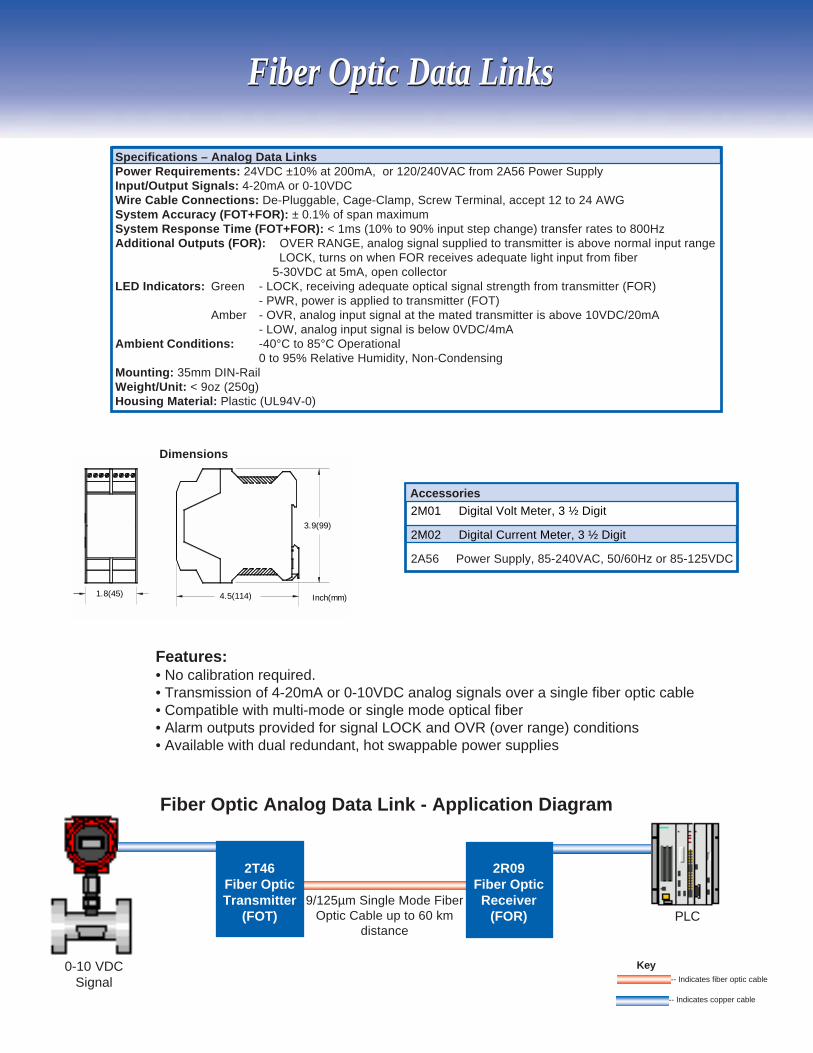
Fiber Optic Analog Data Link - Application Diagram
Fiber Optic Data LinksFiber Optic Data Links
2M01 Digital Volt Meter, 3 ½ Digit
2M02 Digital Current Meter, 3 ½ Digit
2A56 Power Supply, 85-240VAC, 50/60Hz or 85-125VDC
Accessories
Specifications – Analog Data LinksPower Requirements: 24VDC ±10% at 200mA, or 120/240VAC from 2A56 Power SupplyInput/Output Signals: 4-20mA or 0-10VDCWire Cable Connections: De-Pluggable, Cage-Clamp, Screw Terminal, accept 12 to 24 AWGSystem Accuracy (FOT+FOR): ± 0.1% of span maximumSystem Response Time (FOT+FOR): < 1ms (10% to 90% input step change) transfer rates to 800HzAdditional Outputs (FOR): OVER RANGE, analog signal supplied to transmitter is above normal input range LOCK, turns on when FOR receives adequate light input from fiber
5-30VDC at 5mA, open collectorLED Indicators: Green - LOCK, receiving adequate optical signal strength from transmitter (FOR)
- PWR, power is applied to transmitter (FOT)Amber - OVR, analog input signal at the mated transmitter is above 10VDC/20mA
- LOW, analog input signal is below 0VDC/4mAAmbient Conditions: -40°C to 85°C Operational
0 to 95% Relative Humidity, Non-CondensingMounting: 35mm DIN-RailWeight/Unit: < 9oz (250g)Housing Material: Plastic (UL94V-0)
-- Indicates fiber optic cable
-- Indicates copper cable
Key0-10 VDCSignal
9/125µm Single Mode FiberOptic Cable up to 60 km
distance
2T46Fiber OpticTransmitter
(FOT)
2R09Fiber OpticReceiver
(FOR)
1.8(45) 4.5(114)
3.9(99)
Inch(mm)
Dimensions
Features:• No calibration required.• Transmission of 4-20mA or 0-10VDC analog signals over a single fiber optic cable• Compatible with multi-mode or single mode optical fiber• Alarm outputs provided for signal LOCK and OVR (over range) conditions• Available with dual redundant, hot swappable power supplies
PLC
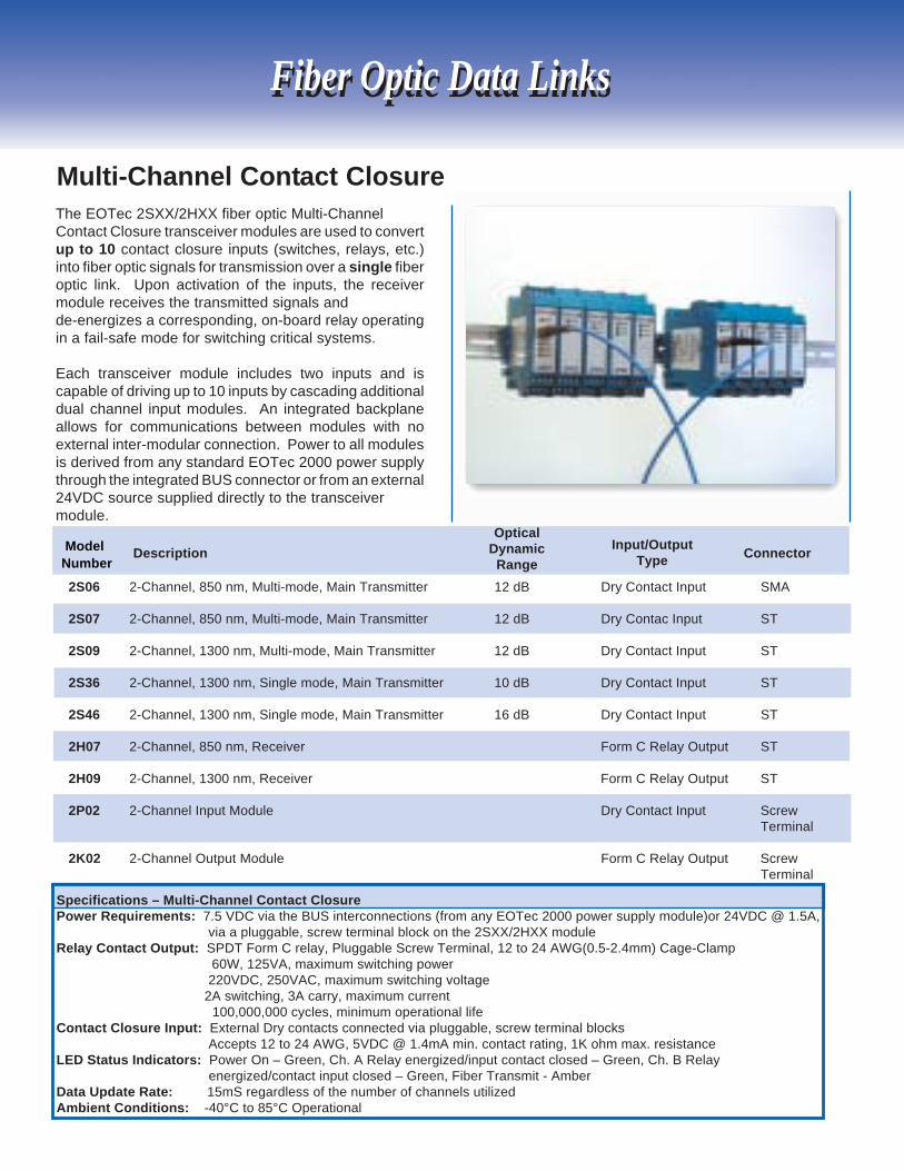
The EOTec 2SXX/2HXX fiber optic Multi-ChannelContact Closure transceiver modules are used to convertup to 10 contact closure inputs (switches, relays, etc.)into fiber optic signals for transmission over a single fiberoptic link. Upon activation of the inputs, the receivermodule receives the transmitted signals andde-energizes a corresponding, on-board relay operatingin a fail-safe mode for switching critical systems.
Each transceiver module includes two inputs and iscapable of driving up to 10 inputs by cascading additionaldual channel input modules. An integrated backplaneallows for communications between modules with noexternal inter-modular connection. Power to all modulesis derived from any standard EOTec 2000 power supplythrough the integrated BUS connector or from an external24VDC source supplied directly to the transceivermodule.
Multi-Channel Contact Closure
Fiber Optic Data LinksFiber Optic Data Links
Description Connector
2S06 2-Channel, 850 nm, Multi-mode, Main Transmitter 12 dB Dry Contact Input SMA
2S07 2-Channel, 850 nm, Multi-mode, Main Transmitter 12 dB Dry Contac Input ST
2S09 2-Channel, 1300 nm, Multi-mode, Main Transmitter 12 dB Dry Contact Input ST
2S36 2-Channel, 1300 nm, Single mode, Main Transmitter 10 dB Dry Contact Input ST
2S46 2-Channel, 1300 nm, Single mode, Main Transmitter 16 dB Dry Contact Input ST
2H07 2-Channel, 850 nm, Receiver Form C Relay Output ST
2H09 2-Channel, 1300 nm, Receiver Form C Relay Output ST
2P02 2-Channel Input Module Dry Contact Input ScrewTerminal
2K02 2-Channel Output Module Form C Relay Output ScrewTerminal
Specifications – Multi-Channel Contact ClosurePower Requirements: 7.5 VDC via the BUS interconnections (from any EOTec 2000 power supply module)or 24VDC @ 1.5A,
via a pluggable, screw terminal block on the 2SXX/2HXX moduleRelay Contact Output: SPDT Form C relay, Pluggable Screw Terminal, 12 to 24 AWG(0.5-2.4mm) Cage-Clamp 60W, 125VA, maximum switching power
220VDC, 250VAC, maximum switching voltage 2A switching, 3A carry, maximum current
100,000,000 cycles, minimum operational lifeContact Closure Input: External Dry contacts connected via pluggable, screw terminal blocks
Accepts 12 to 24 AWG, 5VDC @ 1.4mA min. contact rating, 1K ohm max. resistanceLED Status Indicators: Power On – Green, Ch. A Relay energized/input contact closed – Green, Ch. B Relay
energized/contact input closed – Green, Fiber Transmit - AmberData Update Rate: 15mS regardless of the number of channels utilizedAmbient Conditions: -40°C to 85°C Operational
ModelNumber
OpticalDynamic
RangeInput/Output
Type
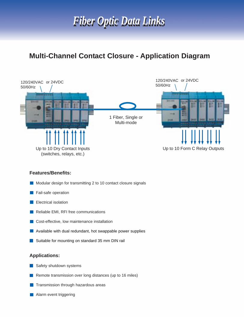
Multi-Channel Contact Closure - Application Diagram
Fiber Optic Data LinksFiber Optic Data Links
120/240VAC50/60Hz
or 24VDC
Up to 10 Dry Contact Inputs(switches, relays, etc.)
1 Fiber, Single orMulti-mode
Up to 10 Form C Relay Outputs
120/240VAC50/60Hz
or 24VDC
Features/Benefits:
Modular design for transmitting 2 to 10 contact closure signals
Fail-safe operation
Electrical isolation
Reliable EMI, RFI free communications
Cost-effective, low maintenance installation
Available with dual redundant, hot swappable power supplies
Suitable for mounting on standard 35 mm DIN rail
Applications:
Safety shutdown systems
Remote transmission over long distances (up to 16 miles)
Transmission through hazardous areas
Alarm event triggering
27
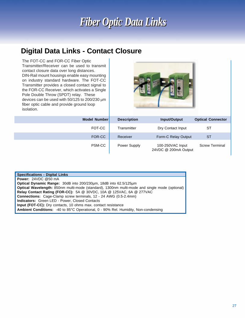
The FOT-CC and FOR-CC Fiber OpticTransmitter/Receiver can be used to transmitcontact closure data over long distances.DIN-Rail mount housings enable easy mountingon industry standard hardware. The FOT-CCTransmitter provides a closed contact signal tothe FOR-CC Receiver, which activates a SinglePole Double Throw (SPDT) relay. Thesedevices can be used with 50/125 to 200/230 µmfiber optic cable and provide ground loopisolation.
Model Number Description Input/Output Optical Connector
FOT-CC Transmitter Dry Contact Input ST
FOR-CC Receiver Form-C Relay Output ST
PSM-CC Power Supply 100-250VAC Input Screw Terminal 24VDC @ 200mA Output
Digital Data Links - Contact Closure
Specifications - Digital LinksPower: 24VDC @50 mAOptical Dynamic Range: 30dB into 200/230µm, 18dB into 62.5/125µmOptical Wavelength: 850nm multi-mode (standard), 1300nm multi-mode and single mode (optional)Relay Contact Rating (FOR-CC): 5A @ 30VDC, 10A @ 125VAC, 6A @ 277VACConnections: Cage-Clamp screw terminals, 12 - 24 AWG (0.5-2.4mm)Indicators: Green LED - Power, Closed ContactsInput (FOT-CC): Dry contacts, 10 ohms max. contact resistanceAmbient Conditions: -40 to 85°C Operational, 0 - 90% Rel. Humidity, Non-condensing
Fiber Optic Data LinksFiber Optic Data Links
28
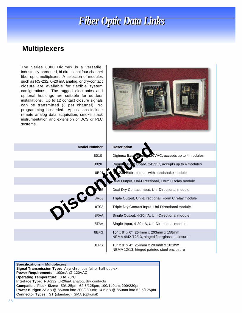
The Series 8000 Digimux is a versatile,industrially-hardened, bi-directional four channelfiber optic multiplexer. A selection of modulessuch as RS-232, 0-20 mA analog, or dry-contactclosure are available for flexible systemconfigurations. The rugged electronics andoptional housings are suitable for outdoorinstallations. Up to 12 contact closure signalscan be transmitted (3 per channel). Noprogramming is needed. Applications includeremote analog data acquisition, smoke stackinstrumentation and extension of DCS or PLCsystems.
Model Number Description
8010 Digimux Base Board, 120VAC, accepts up to 4 modules
8020 Digimux Base Board, 24VDC, accepts up to 4 modules
8B01 RS-232 Bidirectional, with handshake module
8R02 Dual Output, Uni-Directional, Form C relay module
8T02 Dual Dry Contact Input, Uni-Directional module
8R03 Triple Output, Uni-Directional, Form C relay module
8T03 Triple Dry Contact Input, Uni-Directional module
8RAA Single Output, 4-20mA, Uni-Directional module
8TAA Single Input, 4-20mA, Uni-Directional module
8EFG 10" x 8" x 6", 254mm x 203mm x 158mmNEMA 4/4X/12/13, hinged fiberglass enclosure
8EPS 10" x 8" x 4", 254mm x 203mm x 102mmNEMA 12/13, hinged painted steel enclosure
Multiplexers
Specifications - MultiplexersSignal Transmission Type: Asynchronous full or half duplexPower Requirements: 100mA @ 120VACOperating Temperature: 0 to 70°CInterface Type: RS-232, 0-20mA analog, dry contactsCompatible Fiber Sizes: 50/125µm, 62.5/125µm, 100/140µm, 200/230µmPower Budget: 23 dB @ 850nm into 200/230µm; 14.5 dB @ 850nm into 62.5/125µmConnector Types: ST (standard), SMA (optional)
Fiber Optic Data LinksFiber Optic Data Links
Discontinued
29
Nuclear Qualified Fiber Optic Data Link
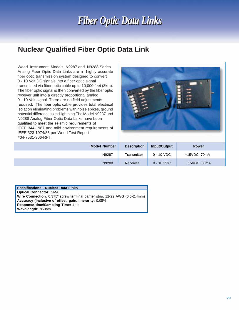
Weed Instrument Models N9287 and N9288 SeriesAnalog Fiber Optic Data Links are a highly accuratefiber optic transmission system designed to convert0 - 10 Volt DC signals into a fiber optic signaltransmitted via fiber optic cable up to 10,000 feet (3km).The fiber optic signal is then converted by the fiber opticreceiver unit into a directly proportional analog0 - 10 Volt signal. There are no field adjustmentsrequired. The fiber optic cable provides total electricalisolation eliminating problems with noise spikes, groundpotential differences, and lightning.The Model N9287 andN9288 Analog Fiber Optic Data Links have beenqualified to meet the seismic requirements ofIEEE 344-1987 and mild environment requirements ofIEEE 323-1974/83 per Weed Test Report#04-7531-306-RPT.
Model Number Description Input/Output Power
N9287 Transmitter 0 - 10 VDC +15VDC. 70mA
N9288 Receiver 0 - 10 VDC ±15VDC, 50mA
Fiber Optic Data LinksFiber Optic Data Links
Specifications - Nuclear Data LinksOptical Connector: SMAWire Connection: 0.375" screw terminal barrier strip, 12-22 AWG (0.5-2.4mm)Accuracy (inclusive of offset, gain, linerarity: 0.05%Response time/Sampling Time: 4msWavelength: 850nm

30
Accessories & Service
Training SeminarsWeed Fiber Optics provides both on-site training programsas well as comprehensive public seminars on topics rangingfrom the basics of fiber optic theory and system design tohands-on fiber termination and cable installation training.Training sessions can run from two hours to three days andcan be custom designed to meet your specific needs.Training is focused on Instrumentation and Controlapplications, and is taught by Weed’s experienced staff.
Accessories & Service
Test EquipmentA comprehensive range of specialized fiber optic testequipment is available for either purchase or rental. Thisequipment includes Optical Time Domain Reflectometers(OTDR), battery-powered Optical Power Meters, light sources,and accessories. Training and on-site support services areavailable for learning how to use the equipment and fordeveloping customized maintenance and troubleshootingprograms.
14
Termination KitsTermination kits are available for 200/230µm fiber sizes forSMA and ST connectors. The kits are easy to use by plantpersonnel and do not require epoxy or polishing, thusproviding cost-effective installation. Fiber optic jumpers andconnectors can also be supplied. These assemblies areextremely rugged to survive harsh plant conditions.

31
Custom EngineeringWeed Instrument design engineers are experts in thefields of fiber optics, multiplexing, signal conditioning, andindustrial control system design. If equipment is neededbeyond our standard product lines, custom designs ormodifications can be provided. The staff also hasimmediate access to other Weed Instrument experts intemperature and pressure sensing equipment andapplications.
Field SupportHighly experienced technicians and engineers are availableto assist in the installation, start-up, maintenance, andtroubleshooting of fiber optic systems. They have extensiveexperience in many types of industrial manufacturing plantsand power facility applications and are available foremergency dispatch or scheduled system start-ups. Ourstaff is equipped with the latest equipment such as OTDRsand digital scopes.
ServicesServices
Customer ServiceTaking care of our customers is priority one for Weed Instrument. We respond to allof their questions and concerns with the greatest respect. We believe it is veryimportant to follow up on every phone call, quote and purchase order for customersatisfaction.
We have the ‘can do’ attitude to make sure our customers are completely confidentin choosing our products for their industrial application. If you should need technicalquestions answered or assistance with installing our products, please contact us, andwe will gladly put you in touch with one of our highly experienced ApplicationsEngineers to make sure your questions are answered promptly.
15

32
Weed Instrument works closely with the leading PLC manufacturers to ensure that our fiber optic modems interfaceproperly with their products. We are members of Rockwell Automation's Encompass program, GE-Fanuc's Accompanyprogram, and Schneider Electric's Alliances program.
PLC Manufacturer ProgramsPLC Manufacturer Programs
Pub: RM0900515Rev. 12/2003
www.weedinstrument.comWeed Instrument Company, Inc., P.O. Box 300, 707 Jeffrey Way, Round Rock, TX 78680
Toll Free: 1-800-880-9333, Phone: (512) 434-2850, Fax: (512) 434-2851,E-Mail: [email protected], Home Page: www.weedinstrument.com
Corporate Profile
Fiber optic products are available immediately from stock.
Weed Instrument Company is a leading supplier of instrumentation and control equipment for industrial, process andpower control applications. Through constant innovation, the company has rapidly expanded since 1968 to become aleading supplier of accurate and reliable sensing devices and data communications equipment for harsh industrialenvironments. Sensing products include temperature sensors, switches and transmitters. Weed Instrument specializesin a wide range of fiber optic and custom products, and provides field support for plant communications,instrumentation, and control applications.
The Fiber Optic division of Weed Instrument was establishedthrough acquisition of two pioneering companies in the applicationof fiber optic technology to the industrial market, EOTec (from 3M)and APEC. Both companies had over ten years of experience inproviding fiber optic solutions specific to factory automation andprocess control. Weed Instrument is continuing this pioneeringspirit through such achievements as being the first company toreceive FM Approval for fiber optic based products in hazardousareas and developing new technologies such as bi-directionalcommunications over a single fiber.
Our staff is comprised of individuals from the I&C industry, andhas a good understanding of the needs and problems specific to industrial applications. We provide complete systemsproduct support including conceptual design, design engineering, manufacturing, testing, field installation, maintenanceand calibration. Currently, Weed Instrument Company has manufacturing, testing and engineering facilities located inRound Rock, Texas.
Alliances