Embed Size (px)
Citation preview

Xuegang Zhang Yongchun Xie Xingqiang Tan
ISSN 1333-1124 eISSN 1849-1391
DESIGN, MESHING CHARACTERISTICS AND STRESS ANALYSIS OF CYLINDRICAL GEARS WITH CURVILINEAR TOOTH PROFILE
Summary
Curvilinear tooth gears are commonly produced on a face milling cutter and a hob cutter. However, this paper proposes a kind of curvilinear tooth gear which is processed by a parallel linkage with a single blade cutter. For the purpose of identifying the meshing and contact characteristics of curvilinear tooth gears, the paper covers the following: (i) equations of tooth surfaces are deduced from the meshing theory, and a parameterized geometric model is developed by applying computer graphics; (ii) an investigation into meshing characteristics for an ideal assembly condition is performed, and an instantaneous contact curve is obtained from the developed tooth contact algorithm; (iii) based on the application of the finite element method, the evolution of contact and bending stresses during the cycle of meshing and between different arc radii of the curvilinear tooth is illustrated by numerical examples. The result shows that curvilinear tooth gear drives possess a higher contact ratio, severe contact stresses on the top edge of the tooth, and lower contact and bending stresses between appropriate arc radii, hence they may replace spur gears in the future.
Key words: parameterized design, meshing characteristics, stress analysis, finite element method, curvilinear tooth gear
1. Introduction
Gear drive is widely applied to a variety of machinery and equipment, and is mainly used to transmit a certain speed ratio and to increase or decrease the transitive torque. With the development of mechanical industry, conventional cylindrical gears (spur gears, helical gears and herringbone gears) have become increasingly inefficient because they have a particular axial force, or poor workability in gear transmission. Therefore, many researchers have focused on designing a new cylindrical gear with the feature of an ordinary spur gear and helical gear which would, however, overcome the shortcomings of the herringbone gear. This type is called a cylindrical gear with curvilinear tooth profile.
Initially, curvilinear tooth gear drives were proposed by the United States patent [1]. In [2], curvilinear tooth gears are machined on face milling spread blade cutters. The mathematical model of curvilinear tooth gears was generated by considering the meshing of a gear blank with a virtual rack cutter, and the undercutting of the curvilinear tooth gear was analyzed by applying the theory of gear. In [3], a mathematical model and contact
TRANSACTIONS OF FAMENA XL-1 (2016) 27

X. G. Zhang, Y. C. Xie Design, Meshing Characteristics and Stress Analysis X. Q. Tan of Cylindrical Gears with Curvilinear Tooth Profile
characteristics of curvilinear tooth gear drives were proposed, and a mathematical model was generated by the proposed rack cutters in [2]. Additionally, in [4], a mathematical model of curvilinear tooth gear was generated by a hob cutter, and the tooth surface deviations due to the machine tool settings with a nominal radius of circular tooth traces were analyzed. In [5], the undercutting and contact characteristics of the curvilinear tooth gear, cut by hob cutters performing the motion with two independent parameters, were investigated. Simultaneously, a mathematical model and a processing method of curvilinear tooth gears by the same hob cutters were also proposed in [6-7].
This paper focuses on the following: (i) The geometry of curvilinear tooth gear drives is generated by a parallel linkage with
a single blade. Computer programs for the parameterized design of the proposed gears are developed by applying computer graphics;
(ii) A kind of algorithm for the simulation of meshing is proposed, based on ideal assembly conditions for curvilinear tooth gear drives. And the influence of different cutter pitch radii on the contact ratio of curvilinear tooth gears will be analyzed;
(iii) Underneath different cutter pitch radii, the contact stresses and the bending stresses will be analyzed by using the finite element method.
2. Parameterized modelling method
Fig. 1 shows a parallel linkage mechanism with a single blade used for machining curvilinear tooth gears. The device is composed of a driver, a support, a linkage, a disc, a blade cutter and four revolute joints. Two discs are connected to the support of the device with revolute joints. Another revolute joint is used for connecting the linkage and two discs. Additionally, the blade cutter is fixed to the end of the linkage. During the production process, the linkage and the blade surface are parallel to the end face of the curvilinear tooth gear. Simultaneously, the blade cutter rotates around the axis of the disc with angular velocity ωc. The distance between the blade cutter and the axis of the disc is rc, which depends on the desired radius of the gear tooth.
Fig. 1 Schematic of parallel linkage mechanism with single blade
During the generation process, the cutter is translated with the linear velocity vc, while the gear blank rotates with the angular velocity ωgb, the cutter pitch plane remains tangent to the gear pitch cylinder. The gear tooth surfaces are generated as the envelope to the family of positions of the blade cutter. The motion of the blade cutter is rolling without slipping over
28 TRANSACTIONS OF FAMENA XL-1 (2016)

Design, Meshing Characteristics and Stress Analysis X. G. Zhang, Y. C. Xie of Cylindrical Gears with Curvilinear Tooth Profile X. Q. Tan
the gear pitch cylinder. The rolling without slipping condition is expressed mathematically by Eq. (2), where rp represents the radius of the gear pitch circle. Additionally, during milling, two discs rotate around their own axes with angular velocity ωc. The value of the angular velocity ωc only depends on the desired cutting velocity and has no effect on the generated geometry of the gear tooth surfaces.
c gb pv r (1)
2.1 Geometry of producing tools Fig. 2 shows a schematic representation of a single blade cutter cross section. The
coordinate axis yc coincides with the axis of the disc in the coordinate system Oc(xc,yc,zc). A blade is composed of an outside blade and an inside blade. The outside blade generates the concave side of the gear tooth surface, and the inside blade generates the convex side of the gear tooth surfaces. If the blade is fixed to the disc, the inside blade has a lower pitch curvature radius than the outside blade, and the bearing contact is achieved between the concave side of the pinion tooth surfaces and the convex side of the wheel tooth surfaces, or vice versa, the curvatures of the generated mating surfaces will be different and, as a result, the curvilinear cylindrical gears generated by this type of cutters will be in point contact. The pitch curvature radii of the outside blade, rob, and the inside blade, rib, are given by:
4ob cmr r
, 4ib cmr r
(2)
Here, rc is the cutter mean pitch radius and m is the module. However, the blade and the linkage are connected to the disc by a revolute joint. Therefore, in fact, the pitch curvature radius of the inside blade is the same as of the outside blade, so the curvilinear cylindrical gears generated by this type of cutters will be in line contact.
Fig. 2. Schematic of single blade cutter cross section
2.2 Geometry of producing profiles of cutting blades Fig. 3 shows the geometry of the blade profiles of a single blade cutter. In the figure,
parameter ρ represents the edge radius of the coefficient, m represents the module, a represents the addendum coefficient, b represents the dedendum coefficient, αn represents the pressure angle, u represents the distance measured from the point Oob or Oib , moving along the straight line to any point Pob or Pib , λ represents the angle measured from the tail end, moving along the fillet line to any point on the fillet line. The points Ofob and Ofib are located at the centre of the fillet line of the outside blade and the inside blade, respectively. The coordinate system Ob(xb, yb, zb) is fixed to the blade. In the case of a single blade cutter, its
TRANSACTIONS OF FAMENA XL-1 (2016) 29

X. G. Zhang, Y. C. Xie Design, Meshing Characteristics and Stress Analysis X. Q. Tan of Cylindrical Gears with Curvilinear Tooth Profile
axis yb is directed along the blade symmetry axis and its origin is located on the blade profile pitch plane. In the case of a fixed setting cutter blade, the plane xbzb coincides with the cutter pitch plane and its origin is separated from the origins of the coordinate systems Oob(xob, yob, zob) and Oib(xib, yib, zib), fixed to the outer and inner blades, respectively. The distance is πm/2 between the coordinate systems Oob(xob, yob, zob) and Oib(xib, yib, zib) . The coordinate system Oib(xib, yib, zib) is fixed to the inner blade cutting profile. Its axis yib is oriented along the cutting edge towards the dedendum of the blade and its origin is located on the pitch plane. The coordinate system Oob(xob, yob, zob) is fixed to the outer blade cutting profile. Its axis yob is oriented along the cutting edge towards the dedendum of the blade and its origin is located on the pitch plane.
Due to its rotation around the disc axis, the blade profile will form the cutter producing surface. Each producing profile is divided into two parts: (i) the main producing profile that will generate the parts of the gear tooth surfaces involved in meshing, and (ii) the blade edge producing profile that will generate the fillets of the gear tooth surfaces. The geometry of the producing profile depends on the cutting side of the blade, the inner or the outer. Subsequently, equations of the blade main producing profiles and the blade edge producing profiles will be derived in a general way to be used in each case.
πm/2 αn
yb
Ob
Pob
xb Oib
y ib
xib
uOob
yob
xobu
Pib
am
bm
λ λOfob Ofib
ρm
Fig. 3 Blade profiles of single blade cutter.
The main producing profile will generate the main active part of the curvilinear gear tooth surfaces and will be provided with a straight profile. In the coordinate systems Oob(xob, yob, zob) and Oib(xib, yib, zib), the vector position of the points Pob and Pib is given by
0
( ) ( ) ( )01
ib obob ob
P PPO O
uu u u
r r r (3)
In Eq. (3), the parameter u is a variational value, due to the points Pob or Pib moving along the straight line. The range of variation of the profile parameter u is
sincos cos
n
n n
bm m m amu
(4)
The produced profiles will be expressed for a single blade cutter in the coordinate system Ob(xb, yb, zb). The coordinate transformation between the coordinate systems Oob(xob, yob, zob) and Oib(xib, yib, zib) is fixed to the inner and the outer cutting profiles, respectively, and the reference coordinate systems Ob(xb, yb, zb) are as follows:
30 TRANSACTIONS OF FAMENA XL-1 (2016)

Design, Meshing Characteristics and Stress Analysis X. G. Zhang, Y. C. Xie of Cylindrical Gears with Curvilinear Tooth Profile X. Q. Tan
,
cos sin 04
sin cos 0 00 0 1 00 0 0 1
n n
n nb ob
m
M (5)
,
cos sin 04
sin cos 0 00 0 1 00 0 0 1
n n
n nb ib
m
M (6)
However, the points Pob and Pib are represented in the coordinate system Oob(xob, yob, zob) and Oib(xib, yib, zib), respectively, as
,
sin4
cos( ) ( )01
ob obb ob
n
P PnO Ob ob
mu
uu u
Mr r (7)
,
sin4
cos( ) ( )01
ib ibb ib
n
P PnO Ob ib
mu
uu u
Mr r (8)
The blade edge producing profile generates the fillet part of the curvilinear gear tooth surfaces and will be provided with a circular arc profile. The coordinates of a point on the edge blade profiles are represented by computing the points Ofob and Ofib as previously described in the coordinate system Ob(xb, yb, zb) as
( tan ( sin ) cos cos )4
sin( )01
f
b
n n n
OO
m bm m m m m
m m bm
r
(9)
Therein, the upper sign represents a point on the blade edge outer side; the lower sign represents a point on the blade edge inner side. The variation range of parameter λ is
2n (10)
2.3 Geometry of single blade cutter producing surfaces Based on the working principle of the parallel linkage mechanism, a set of reference
coordinate systems have been defined (see Fig. 4). Parameter FW represents the face width of the curvilinear gear to be generated. The coordinate system Oc(xc, yc, zc) fixed to the centre of rotation of the disc will be considered for derivation of the geometry of the single blade
TRANSACTIONS OF FAMENA XL-1 (2016) 31

X. G. Zhang, Y. C. Xie Design, Meshing Characteristics and Stress Analysis X. Q. Tan of Cylindrical Gears with Curvilinear Tooth Profile
cutter. The coordinate system Ob(xb, yb, zb) is fixed to the blade profile and the coordinate system Oc(xc, yc, zc) is fixed to the disc. Coordinate transformation from the coordinate system Ob(xb, yb, zb) to Oc(xc, yc, zc) is given by matrix Mc,b and simulates the rotation of the producing blade profile around the axis of the disc.
Fig. 4 Sketch of coordinate transformation from Ob(xb, yb, zb) to Oc(xc, yc, zc) on single blade cutter pitch plane.
,
1 0 0 cos0 1 0 0( ) 0 0 1 sin0 0 0 1
c
c bc
r
r
M (11)
where
sin sin2 2
W W
c c
F Farc arcr r
(12)
The single blade cutter producing surfaces in the coordinate system Oc(xc, yc, zc) are represented as follows:
1 ,
( sin ) cos4
cos( , ) ( ) ( )sin1
b
n c
P PnO c b O
c
mu r
uu ur
r M r
(13)
,
( tan ( sin ) cos cos ) cos4
sin( , ) ( ) ( )sin1
f f
c b
n n n c
O OO c b O
c
m bm m m m m r
m m bmr
r M r
(14)
Herein, Eq. (13) represents the main producing surface of the blade; Eq. (14) represents the edge producing surfaces of the blade.
2.4 Derivation of equations of meshing Fig. 5 shows a sketch of coordinate transformation from Oc(xc, yc, zc) to O1(x1, y1, z1) for
the curvilinear tooth gear generation process. The coordinate system O1(x1, y1, z1) is fixed to the generated gear, and the coordinate system Oc(xc, yc, zc) is fixed to the disc. The single blade cutter translates a distance r1φ1 during the gear generation process while the gear blank
Cutter pitch
32 TRANSACTIONS OF FAMENA XL-1 (2016)

Design, Meshing Characteristics and Stress Analysis X. G. Zhang, Y. C. Xie of Cylindrical Gears with Curvilinear Tooth Profile X. Q. Tan
rotates through an angle φ1. The coordinate transformation from the coordinate system Oc(xc, yc, zc) to the coordinate system O1(x1, y1, z1) is given by Eq. (15). The parametric representation of the family of the single blade cutter producing surfaces in the reference coordinate system O1(x1, y1, z1) is given by Eqs. (16) and (17).
yc
Oc
xc
y' c
O'c x' c
y f
,Of
xf
y1
x1
O1
φ1
φ1
rp
rpφ1
Fig. 5 Sketch of coordinate transformation from Oc(xc, yc, zc) to O1(x1, y1, z1)
1 1 1 1 1
1 1 1 1 11, 1
cos sin 0 (sin cos )sin cos 0 (cos sin )( )
0 0 1 00 0 0 1
p
pc
rr
M (15)
1
1 1
111 1, 1
1 1
( , , )( , , )( , , ) ( ) ( , )( , , )
1
c
P
PP P
O c O P
uuu uu
xyz
r M r (16)
1
1 1
111 1, 1
1 1
( , , )( , , )( , , ) ( ) ( , )( , , )
1
f
ff f
c f
O
OO OO c O O
xyz
r M r (17)
By introducing Eqs. (13), (14) and (15) into Eqs. (16) and (17), respectively, the components of the vectors
1
POr and
1
fOOr are given by Eqs. (18) and (19).
1 1 1 1 1
1 1
1 1
11
1
1 1
1
1
( , , ) sin
( , , ) s
cos sin cos cos cos sin4
sin cos cos sinin
( ,
cos cos4
s, i) n
P
Pn
n c p n
c
P
p n
c
m u r r u
m u r r u
r
u
u
u
x
yz
(18)
Pitch cylinder
Cutter pitch plane
TRANSACTIONS OF FAMENA XL-1 (2016) 33

X. G. Zhang, Y. C. Xie Design, Meshing Characteristics and Stress Analysis X. Q. Tan of Cylindrical Gears with Curvilinear Tooth Profile
1
1
1
1 1 1
1 1
1
1
1
11
( , , )
( , , ) si
cos tan sin cos cos cos4
sin sin 1
tan sin cos cos cos4
cos
n
( ,
sin 1
)
si
,
cos n
f
f
f
n n n c
n n n
p
O
O
O
c
mbm m m m m r
bm m
mbm m m m m r
bm m r
x
y
z
sincr (19)
The equation of meshing represents the necessary condition of existence of the envelope to a family of surfaces. This equation of meshing is satisfied and the gear tooth surface indeed exists if it remains tangent to its producing tool surface. The sufficient conditions of existence of the envelope to a family of surfaces are as follows:
1 1 11
1
( , , ) 0P P P
O O Of uu
r r r (20)
1 1 11
1
( , , ) 0f f fO O O
O O Of
r r r (21)
By substituting Eqs. (16) and (17) into Eqs.(18) and (19), respectively, the equations of meshing corresponding to the gear tooth surfaces being generated are derived.
1 1
1 1 1 1
1
1
1 1
1 1 1
( , , )
( , )
cos cos sin cos sin
cos cos cos sin
cos sin sin cos cos
sin sin cos cos
s
(
in cos
, ) 0
( , )4
c n n
p n
c n n
p n
n c
f u
g u
g u
g
r
r u
r
r u
m u ru
(22)
1
2
1 1
1 1 1
1 1
1 1 1
1
1 2
1
cos cos sin cos sin
sin cos cos
cos sin sin cos co
( , , )
( ) ( , )
( , ) ( )
s
sin cos sin 0
tan sin cos4
cos co
( , )
s
c
p
c
p
n n c
r m m
r
r m m
r
m bm m m r
m m
f
p p
p p
p
2 sin( 1 ) bm mp
(23)
34 TRANSACTIONS OF FAMENA XL-1 (2016)

Design, Meshing Characteristics and Stress Analysis X. G. Zhang, Y. C. Xie of Cylindrical Gears with Curvilinear Tooth Profile X. Q. Tan
2.5 Geometry of curvilinear tooth gear tooth surface When equations of meshing (22) and (23) for the active and the fillet tooth surfaces,
respectively, are satisfied, the envelope to the family of the producing cutter surfaces in the coordinate system O1(x1, y1, z1) will exist and the curvilinear gear tooth surfaces can be obtained by Eqs. (24) and (25). Similarly, the pinion tooth surfaces can be produced by utilizing the same parallel linkage mechanism with a single blade that produces gear tooth surfaces. Therefore, a mathematical model of the pinion tooth surfaces can also be developed by applying the process described above.
1,1 11
1
( , , ) ( ) ( , )
( , , ) 0
P PcO Oc
u u
f u
r M r (24)
1,1 11
1
( , , ) ( ) ( , )
( , , ) 0
O Of fcO Oc
u
f u
r M r (25)
2.6 Computer graphics of the parameterized models Computer programs for designing curvilinear tooth surfaces of the mathematical model
(see section 2.1) can be developed by the MATLAB mathematical software. The data point on the curvilinear tooth surfaces (the concave side and the convex side of the curvilinear tooth gear) can be obtained by the developed user interface of the parameterized tooth surfaces (Fig. 4). Then, the determinate data file input CAD software (such as Pro/Engineer) is utilized to produce a three-dimensional solid model.
Some major design parameters of the curvilinear tooth gears are shown in Table 1 (Case 1). A three-dimensional gear tooth profile of the curvilinear tooth gear can be obtained by the developed computer programs as depicted in Fig. 6.
Fig. 6 User interface for generation of parametric tooth surface
TRANSACTIONS OF FAMENA XL-1 (2016) 35
X. G. Zhang, Y. C. Xie Design, Meshing Characteristics and Stress Analysis X. Q. Tan of Cylindrical Gears with Curvilinear Tooth Profile
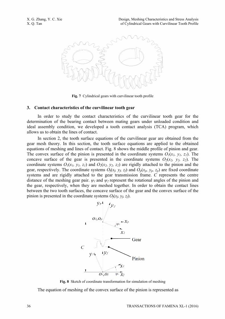
Fig. 7 Cylindrical gears with curvilinear tooth profile
3. Contact characteristics of the curvilinear tooth gear
In order to study the contact characteristics of the curvilinear tooth gear for the determination of the bearing contact between mating gears under unloaded condition and ideal assembly condition, we developed a tooth contact analysis (TCA) program, which allows us to obtain the lines of contact.
In section 2, the tooth surface equations of the curvilinear gear are obtained from the gear mesh theory. In this section, the tooth surface equations are applied to the obtained equations of meshing and lines of contact. Fig. 8 shows the middle profile of pinion and gear. The convex surface of the pinion is presented in the coordinate systems O1(x1, y1, z1). The concave surface of the gear is presented in the coordinate systems O2(x2, y2, z2). The coordinate systems O1(x1, y1, z1) and O2(x2, y2, z2) are rigidly attached to the pinion and the gear, respectively. The coordinate systems Of(xf, yf, zf) and Op(xp, yp, zp) are fixed coordinate systems and are rigidly attached to the gear transmission frame. C represents the centre distance of the meshing gear pair. ψ1 and ψ2 represent the rotational angles of the pinion and the gear, respectively, when they are meshed together. In order to obtain the contact lines between the two tooth surfaces, the concave surface of the gear and the convex surface of the pinion is presented in the coordinate systems Of(xf, yf, zf).
Fig. 8 Sketch of coordinate transformation for simulation of meshing
The equation of meshing of the convex surface of the pinion is represented as
36 TRANSACTIONS OF FAMENA XL-1 (2016)

Design, Meshing Characteristics and Stress Analysis X. G. Zhang, Y. C. Xie of Cylindrical Gears with Curvilinear Tooth Profile X. Q. Tan
11 1 ,1 1 1( , , , ) ( ) ( , , )ob obf
P PO Ofu u Mr r (26)
1 1
1 1,1 1
cos sin 0 0sin cos 0 0( ) 0 0 1 0
0 0 0 1
f
M (27)
Where matrix Mf,1 indicates the coordinate transformation from the coordinate system O1(x1, y1, z1) to Of(xf, yf, zf).
The equation of meshing of the concave surface of the gear is represented as
21 2 , ,2 2 1( , , , ) ( ) ( , , )ib ibf
P PO Of p pu u M Mr r (28)
,
1 0 0 00 1 00 0 1 00 0 0 0
f pC
M (29)
2 2
2 2,2 2
cos sin 0 0sin cos 0 0( ) 0 0 1 0
0 0 0 1
p
M (30)
Where matrix Mf,p indicates the coordinate transformation from the coordinate system Op(xp, yp, zp) to Of(xf, yf, zf). Matrix Mp,2 indicates the coordinate transformation from the coordinate system O2(x2, y2, z2) to Op(xp, yp, zp).
The relationship between ψ1 and ψ2 is as follows:
1
2
g
p
zz
(31)
Where zp and zg are the pinion and the gear tooth numbers, respectively. To get the contact curve between the convex surface of the pinion and the concave
surface of the gear, the authors have developed a computer program for the TCA under unloaded condition and ideal assembly condition as a new approach. The program can be used for the simulation of meshing of spur gears, helical gears etc. The computational procedure is as follows (Fig. 9):
Step 1: Using the equations of meshing (26) and (28) to compute discrete point coordinates of involutes on the convex surface of the pinion and the concave surface of the gear which are laid on the uniform step factor θ;
Step 2: Seeking the boundary of the common x-coordinates of the two involutes; Step 3: Merging the common x-coordinates xi of the two involutes to solve the y-
coordinates y(xi) of one-to-one correspondence based on the geometrical interpolation method; Step 4: Finding xi and the corresponding y (xi) when y2 (xi) - y1 (xi) =0; Step 5: Creating a fit curve (contact curve) along the generated points on the tooth surface; Step 6: Varying the parameter θ, and repeating steps 1-4 until all contact points on the
gear tooth surface are obtained.
TRANSACTIONS OF FAMENA XL-1 (2016) 37

X. G. Zhang, Y. C. Xie Design, Meshing Characteristics and Stress Analysis X. Q. Tan of Cylindrical Gears with Curvilinear Tooth Profile
x
y
x1 x2
y 1 (xi) - y 2 (xi)=0
x2 = x2 (t2)y 2 = y 2 (t2)
x1 = x1 (t1)y 1 = y 1 (t1){
y 2 (x1)
y 1 (x1)
y 2 (x2)
y 1 (x2)
xiO
{
Fig. 9 Illustration of computations for contact point on tooth surfaces
The first contact curve is generated by the proposed approach; we obtain the second contact curve when the rotational angles ψ1 and ψ2 of two equations are modified. The contact curve of more positions is calculated by parity of reasoning. Fig. 10 shows the contact curves on the convex surface of the pinion and the concave surface of the gear under ideal assembly condition, respectively. The contact curves are plotted when the pinion is rotated every 4° from 0° to 32°. The major design parameters of the pinion and the gear are zp = zg =20, m =4, rc =30, Fw=30.
Fig. 10 Contact curves on (a) convex surface of pinion and (b) concave surface of gear
under ideal assembly condition.
Fig. 10 shows: (i) the contact curve is a symmetrical space curve around the middle cross section, and therefore the axial thrust force is counterbalanced by the mesh motion; (ii) the contact curve is longer than the face width in the range from 8° to 24°, so the contact ratio is higher than that of the spur gear; (iii) the contact curve is shorter than the other instantaneous curve when the gear pair enters and exits the meshing area.
4. Application of finite element method for curvilinear tooth gears
The goals of the application of the FEM are: (i) under the given torque, the contact stress and the bending stress of different positions of meshing are obtained by considering three-tooth meshing in Case 1 and Case 2; (ii) the contact stress and the bending stress of different arc radii are obtained by considering one-tooth meshing in Case 1.
38 TRANSACTIONS OF FAMENA XL-1 (2016)

Design, Meshing Characteristics and Stress Analysis X. G. Zhang, Y. C. Xie of Cylindrical Gears with Curvilinear Tooth Profile X. Q. Tan
The application of the finite element method requires the development of finite element models which are formed of a finite element mesh, the definition of contacting surfaces, and the establishment of boundary conditions and loading of the gear drive with a desired torque. The detailed procedures are as follows:
Step 1: Using the volume of the designed body (see section 2), the commercial software HyperMesh is applied to generate a desired element. Fig. 11 (a) describes the designed body for one-tooth model of the pinion of a curvilinear tooth gear drive;
Step 2: In order to control the quality of these finite elements, the one-tooth model is divided into six subvolumes by auxiliary intermediate surfaces 1-6 as shown in Fig. 11 (b);
Step 3: 2-D elements are established on the profile of each of the six subvolumes; Step 4: The number of the desired 3-D elements is preformed by using 2-D elements in
the previous step, dragging along the longitudinal surfaces of the subvolumes, as shown in Fig. 11 (c).
Step 5: We will renumber all nodes and 3-D elements; the element type (C3D8I) and the property of the material (Young’s Modulus E=2.06×10⁵ N/mm2 and Poisson’s ratio 0.3) are given to the all elements; the computer will produce the file which includes information on the finite element.
Step 6: Setting of boundary conditions and constraints is accomplished as follows (Fig. 12):
(i) A reference point located on the axis of the master pinion is used as a reference point of the previously defined coupling surfaces. The torque T is applied directly to the remaining degree (the degree of freedom around the z-axis rotation and other degrees of freedom are fixed) of the reference point (Fig. 12 (a)).
(ii) Nodes on the previously defined fixed surfaces of the slave gear are considered fixed (Fig. 12 (b)).
Step 7: The surface-to-surface contact, finite sliding, and friction coefficient (0.25), etc. are used for defining the contacting surfaces. The surfaces on the master pinion are defined as master surfaces; similarly, the surfaces on the slave gear are defined as slave surfaces for the contact algorithm.
More details about the applied approach in the TCA are given in References 8-12.
(a) (b) (c)
Fig. 11 Schematic of: (a) volume of designed body; (b) auxiliary intermediate surfaces; (c) discretization of volume by finite elements.
TRANSACTIONS OF FAMENA XL-1 (2016) 39

X. G. Zhang, Y. C. Xie Design, Meshing Characteristics and Stress Analysis X. Q. Tan of Cylindrical Gears with Curvilinear Tooth Profile
(a) (b)
Fig. 12 (a) Schematic of boundary conditions and application of torques for pinion, (b) Boundary conditions for gear.
5. Numerical examples
The gear pairs with curvilinear tooth profile are sensitive to the axial misalignments and smaller assembly errors; but the assembly of the gear pair is harder than the assembly of any other gear pair. In order to reduce the difficulty of installation, we have to increase slightly the radius of the concave surface relative to the convex surface (see Case 2 in Table 1).
An example of curvilinear tooth gears with the gear ratio of 20×30 is considered for the investigation of the evolution of the contact and the bending stresses on the gear. The contact point of the gear pairs of a standard configuration (see Case 1 in Table 1) is located at the pitch cercal. The curvilinear tooth radius is increased every 3mm from 21mm to 66mm. The torque applied to all examples for investigating the formation of the bearing contact is 100N·m.
Table 1 Main parameters of curvilinear tooth gears for the designed two cases.
Parameters Case 1 Case 2 Pinion Gear Pinion Gear
Circumferential modulus (mm) 4 4 4 4 Number of tooth 20 30 20 30 Face width (mm) 30 30 30 30 Convex radius (mm) 30 30 30 30 Concave radius (mm) 30 30 30.1 30.1 Modification coefficient 0 0 0 0 Addendum coefficient 1 1 1 1 Tip clearance coefficient 0.25 0.25 0.25 0.25 Pressure angle (deg) 20 20 20 20
For every case of the curvilinear tooth radius, the generation of results has to be done in a repeated way. Fig. 13 (a) illustrates that evolution of contact stresses on the gears. The contact stresses reach a minimum of 337MPa when the arc radius equals 21mm; the contact stresses reach a maximum of 415MPa when the arc radius equals 66mm. The contact stresses increase along with the increase in the arc radius between 21mm and 66mm. Therefore, we conclude that the contact stresses will approximate infinitely the contact stresses on the spur gear. Fig. 13 (b) shows the evolution of bending stresses on the gear. The bending stresses decrease along with the increase in the arc radius between 21mm and 30mm; the bending stresses increase along with the increase in the arc radius between 30mm and 66mm. We deduce that the bending stresses will approximate infinitely the bending stresses of the spur gear when the arc radius equals infinite. There is a minimum bending stress between 27mm and 39mm.
40 TRANSACTIONS OF FAMENA XL-1 (2016)

Design, Meshing Characteristics and Stress Analysis X. G. Zhang, Y. C. Xie of Cylindrical Gears with Curvilinear Tooth Profile X. Q. Tan
Consequently, it is quite important to reasonably choose the arc radius of curvilinear tooth gears. If the arc radius is too small, the normal thickness of the portions of the rims will be reduced; conversely, the bending stresses on the gear will be increased. Hence, the arc radius should be reasonably controlled.
Fig. 14 illustrates the evolution of the contact and the bending stresses for Case 1 and Case 2 of the three-tooth model of the curvilinear tooth gear. The rotational angle of the three-tooth model is increased every 3 deg from 0 to 18 deg for the whole cycle of meshing. For every position of meshing, the generation of the models has to be done in a repeated way. The comparison of the results relating to both the contact and the bending stresses is larger in Case 2 than in Case 1. Fig. 14 (a) shows that the contact stresses reach a maximum of 322MPa at the top edge of the pinion tooth surface in Case 1 (see Fig. 15 (a)) and a maximum of 599MPa at the top edge of the pinion tooth surface in Case 2 (see Fig. 15 (b)). Fig. 14 (b) and (d) show that the contact of one tooth occurs on the tooth surfaces when the magnitudes of the rotational angle equal 12 deg. Fig. 14(c) illustrates the contact which occurs at the top edge of the gear tooth surface when the magnitudes of the rotational angle equal 15 deg. The contact stresses for Case 1 and Case 2 at the favorable contact point are shown in Fig. 16. The contact length is longer in Case 1 than in Case 2 for two pairs of pinion convex tooth surfaces.
Pinion Contact Stresses
0100200300400500600700
0 3 6 9 12 15 18Rotational angle(deg)
Con
tact
Stre
ss (M
Pa)
Case 1 Case 2
Pinion Bending Stresses
203040506070
0 3 6 9 12 15 18Rotational angle( deg)
Ben
ding
Stre
ss (M
Pa)
Case 1 Case 2
Gear Contact Stresses
320
340
360
380
400
420
440
20 30 40 50 60 70Arc Radius( mm )
Con
tact
Stre
ss (M
pa)
Gear Bending Stresses
505560657075808590
20 30 40 50 60 70Arc Radius (mm)
Ben
ding
Stre
ss (M
pa)
Fig. 13 Evolution of (a) contact stresses and (b) bending stresses on gear
(a)
(b)
(a)
(b)
TRANSACTIONS OF FAMENA XL-1 (2016) 41

X. G. Zhang, Y. C. Xie Design, Meshing Characteristics and Stress Analysis X. Q. Tan of Cylindrical Gears with Curvilinear Tooth Profile
Gear Contact Stresses
0100200300400500600700
0 3 6 9 12 15 18Rotational angle(deg)
Con
tact
Stre
ss (M
Pa)
Case 1 Case 2 Gear Bending Stresses
20
30
40
50
60
70
0 3 6 9 12 15 18Rotational angle(deg)
Ben
ding
stre
ss (M
Pa)
Case 1 Case 2 Fig. 14 Evolution of: (a) pinion contact stresses, (b) pinion bending stresses, (c) gear contact stresses,
and (d) gear bending stresses for Case 1 and Case 2 of curvilinear tooth gear
Fig. 15 Contact stresses for (a) Case 1 and (b) Case 2 at unfavorable contact point
(c)
(d)
(a)
(b)
42 TRANSACTIONS OF FAMENA XL-1 (2016)

Design, Meshing Characteristics and Stress Analysis X. G. Zhang, Y. C. Xie of Cylindrical Gears with Curvilinear Tooth Profile X. Q. Tan
Fig. 16 Contact stresses for (a) Case 1 and (b) Case 2 at favorable contact point
6. Conclusions
The following conclusions can be drawn from the performed investigation: (i) The computer programs are developed based on the application of Matlab for a
parametric geometric model of curvilinear tooth gear drives. The time consumption is reduced in the finite element analysis and the accuracy of the geometric model is increased.
(ii) The contact ratio decreases with the increase in the arc radius. (iii) The contact and the bending stresses on the curvilinear tooth gears are lower than in
the case of the spur gears, and, the endurance of curvilinear tooth gears decreases with the increase in the arc radius.
(iv) A relaxed assembly condition can be obtained by increasing the radius of the concave surface slightly.
(v) The application of the stress analysis allows severe contact stresses to be discovered on the top edge of tooth. In order to eliminate the severe contact stresses, further studies should explore the modification of gear drivers.
Acknowledgements The authors express their deep gratitude to Panzhihua University and the Solar Energy
Integration Technology Popularization and Application Key Laboratory of Sichuan Province (TYN2015-02) for the financial support.
(a)
(b)
TRANSACTIONS OF FAMENA XL-1 (2016) 43

X. G. Zhang, Y. C. Xie Design, Meshing Characteristics and Stress Analysis X. Q. Tan of Cylindrical Gears with Curvilinear Tooth Profile
REFERENCES [1] Tamotsu Koga. Method for Cutting Paired Gears having Arcuate Tooth Trace[P].American: 3915060,
1975.
[2] R. T. Tseng, C. B. Tsay, Mathematical model and undercutting of cylindrical gears with curvilinear shaped teeth, Mechanism and Machine Theory 2001; 36: 1189–1202.
[3] R. T. Tseng, C. B. Tsay, Contact characteristics of cylindrical gears with curvilinear shaped teeth, Mechanism and Machine Theory 2004; 39: 905–919.
[4] J. T. Tseng, C. B. Tsay, Mathematical model and surface deviation of cylindrical gears with curvilinear shaped teeth cut by a hob cutter, Journal of Mechanical Design 2005; 45: 982–987.
[5] J. T. Tseng, C. B. Tsay, Undercutting and contact characteristics of cylindrical gears with curvilinear shaped teeth generated by hobbing, Journal of Mechanical Design 2006; 45: 634–643.
[6] Ariga Y., Ishii H., and Dai Y., 2004, “Study on Investigation the Hobbing of a Curvilinear-tooth Gear (1st Report, Hobbing method)” Proc. of Mechanical Engineering Congress of the Japan Society of Mechanical Engineers, Paper No. 04-1(4), pp. 123–124.
[7] Ariga Y., Wakihira K., and Azuma K., 2004, “Study on Investigation the Hobbing of a Curvilinear-tooth Gear (2nd Report, Its Application to a Gear Pump)” Proc. of Mechanical Engineering Congress of the Japan Society of Mechanical Engineers, Paper No. 04-2, pp. 9–10.
[8] Faydor L. Litvin, Alfonso Fuentes, Qi Fan, Robert F. Handschuh, Computerized design, simulation of meshing, and contact and stress analysis of face-milled formate generated spiral bevel gears, Mechanism and Machine Theory 2002; 37: 441–459.
[9] John Argyris, Alfonso Fuentes, Faydor L. Litvin, Computerized integrated approach for design and stress analysis of spiral bevel gears, Computer Methods in Applied Mechanics and Engineering 2002; 191 ( 11): 1087–1095.
[10] Faydor L. Litvin, Alfonso Fuentes, Kenichi Hayasaka, Design, manufacture, stress analysis, and experimental tests of low-noise high endurance spiral bevel gears, Mechanism and Machine Theory 2006; 41: 83–118.
[11] Ignacio Gonzale-Perez, Jose L.Iserte, Alfonso Fuentes, Implementation of Hertz theory and validation of a finite element model for stress analysis of gear drives with localized bearing contact, Mechanism and Machine Theory 2011; 46: 765–783.
[12] Zheng-Xiang Zhang, Zhang-Hua Fong, Yu-Huo Li, A study of the contact stress analysis of cylindrical gears using the hybrid finite element method, Proc IMechE Part C:J Mechanical Engineering Science 2012; 227(1): 3–18.
Submitted: 04.7.2015 Accepted: 28.01.2016
Xuegang Zhang Yongchun Xie Xingqiang Tan College of Mechanical Engineering, Panzhihua University, Panzhihua, SichuanProvince, PR China [email protected]
44 TRANSACTIONS OF FAMENA XL-1 (2016)


![Research on Stress Characteristics of Shunt Reactor ...PD-M4-8]_201.pdf · Research on Stress Characteristics of Shunt Reactor Considering Magnetic and Magnetostrictive Anisotropy](https://img.dokumen.tips/doc/110x75/5b1b41a67f8b9a32258e5113/research-on-stress-characteristics-of-shunt-reactor-pd-m4-8201pdf-research.jpg)