Embed Size (px)
DESCRIPTION
Structural Design Criteria for Buildings
Citation preview

TI 809-021 September 1999
Technical Instructions
Structural Design Criteriafor Buildings
HeadquartersU.S. Army Corps of EngineersEngineering and Construction DivisionDirectorate of Military ProgramsWashington, DC 20314-1000

CEMP-E TI 809-02 1 September 1999
TECHNICAL INSTRUCTIONS
Structural Design Criteria for Buildings
Any copyrighted material included in this document is identified at its point of use.Use of the copyrighted material apart from this document must have the permission of the copyrighted
holder.
Approved for public release; distribution is unlimited.
Record of Changes (changes indicated \1\ . . . /1/.)No. Date Location

CEMP-E TI 809-021 September 1999
FOREWORD
These technical instructions (TI) provide design and construction criteria and apply to all U.S.Army Corps of Engineers (USACE) commands having military construction responsibilities. TIwill be used for all Army projects and for projects executed for other military services or workfor other customers where appropriate.
TI are living documents and will be periodically reviewed, updated, and made available tousers as part of the HQUSACE responsibility for technical criteria and policy for new militaryconstruction. CEMP-ED is responsible for administration of the TI system; technical content ofTI is the responsibility of the HQUSACE element of the discipline involved. Recommendedchanges to TI, with rationale for the changes, should be sent to HQUSACE, ATTN: CEMP-ED,20 Massachusetts Ave., NW, Washington, DC 20314-1000.
TI are effective upon issuance. TI are distributed only in electronic media through theTECHINFO Internet site http://www.hnd.usace.army.mil /techinfo/index.htm and theConstruction Criteria Base (CCB) systems maintained by the National Institute of BuildingSciences at Internet Site http://www.nibs.org/ccb/. Hard copies of these instructions producedby the user from the electronic media should be checked against the current electronic versionprior to use to assure that the latest instructions are used.
FOR THE COMMANDER:
DWIGHT A. BERANEK, P.E.Chief, Engineering and Construction DivisionDirectorate of Military Programs

i
DEPARTMENT OF THE ARMY TI 809-02U.S. Army Corps of Engineers
CEMP-E Washington, DC 20314-100
Technical InstructionsNo. 809-021 September 1999
STRUCTURAL DESIGN CRITERIA FOR BUILDINGS
Table of Contents
PageCHAPTER 1. GENERAL
Paragraph 1-1. PURPOSE AND SCOPE....................................................................... 1-1
1-2. APPLICABILITY..................................................................................... 1-1
1-3. REFERENCES....................................................................................... 1-1
1-4. BACKGROUND ..................................................................................... 1-1
1-5. ALTERNATIVE AND SPECIAL DESIGNS ............................................. 1-2
1-6. DESIGN LOADS ................................................................................... 1-2
1-7. COMBINATION OF LOAD EFFFECTS .................................................. 1-3
1-8. STRENGH AND SERVICEABILITY PERFORMANCEOBJECTIVES......................................................................................... 1-4
1-9. LOAD PATH CONTINUITY AND INTEGRITY… .................................... 1-4
1-10. OVERSEAS CONSTRUCTION.............................................................. 1-4
1-11. SERVICE LIFE....................................................................................... 1-4
1-12. STABILITY........................................................................................... 1-4
1-13. SPECIAL INSPECTIONS....................................................................... 1-5
CHAPTER 2. BASIC STRUCTRAL SYSTEMS FOR BUILDINGS
Paragraph 2-1. SELECTION OF STRUCTURAL SYSTEM............................................. 2-1
2-2. COMMONLY USED STRUCTURAL SYSTEMS..................................... 2-1
2-3. BUILDING SYSTEM USE IN MILITARY CONSTRUCTION ................... 2-3
2-4. CHARACTERISTICS IMPORTANT TO BUILDINGPERFORMANCE ................................................................................... 2-4

CEMP-E TI 809-021 September 1999
Table of Contents (cont’d) Page
ii
CHAPTER 3. FOOTINGS AND FOUNDATIONS
Paragraph 3-1. GENERAL ............................................................................................... 3-1
3-2. DESIGN.................................................................................................. 3-1
3-3. FOUNDATIONS AND SOIL INVESTIGATIONS ..................................... 3-1
3-4. ALLOWABLE LOAD-BEARING VALUES AND LATERAL SLIDING RESISTANCE OF SOILS ....................................... 3-1
3-5. FOOTINGS AND FOUNDATIONS.......................................................... 3-1
3-6. DEEP FOUNDATIONS ........................................................................... 3-2
3-7. FOUNDATIONS FOR MACHINERY ….................................................... 3-4
3-8. SPECIAL INSPECTIONS ....................................................................... 3-5
CHAPTER 4. CONCRETE STRUCTURE DESIGN REQUIREMENTS
Paragraph 4-1. INTRODUCTION.................................................................................... 4-1
4-2. BASIS FOR DESIGN ............................................................................ 4-1
4-3. EARTHQUAKE RESISTANT DESIGN .................................................. 4-1
4-4. DESIGN STRENGTHS ......................................................................... 4-1
4-5. DESIGN CHOICES …............................................................................ 4-2
4-6. SEVICEABILITY ................................................................................... 4-2
4-7. LOAD PATH INTEGRITY ...................................................................... 4-5
4-8. DETAILING REQUIREMENTS .............................................................. 4-8
4-9. SPECIAL INSPECTIONS ...................................................................... 4-9
CHAPTER 5. SLABS ON GRADE
Paragraph 5-1. INTRODUCTION … ................................................................................ 5-1
5-2. BASIS FOR DESIGN … .......................................................................... 5-1
5-3. SERVICEABILITY …................................................................................ 5-2
5-4. SHRINKAGE COMPENSATING CONCRETE … ..................................... 5-7
5-5. POST-TENSIONED SLABS ………………………………………… ........... 5-7

CEMP-E TI 809-021 September 1999
Table of Contents (cont’d) Page
iii
5-6. SPECIAL TESTS AND SPECIAL INSPECTIONS ………………….. ........ 5-7
CHAPTER 6. MASONRY
Paragraph 6-1. INTRODUCTION..................................................................................... 6-1
6-2. BASIS FOR DESIGN .............................................................................. 6-1
6-3. SERVICEABILITY .................................................................................. 6-1
6-4. LOAD PATH INTEGRITY ....................................................................... 6-1
6-5. SPECIAL INSPECTIONS ……………………………………………............ 6-1
CHAPTER 7. STEEL STRUCTURE DESIGN REQUIREMENTS
Paragraph 7-1. INTRODUCTION… ................................................................................. 7-1
7-2. GENERAL ……………………………………………………………. ............ 7-1
7-3. BASIS FOR DESIGN …………………………………………………........... 7-1
7-4. SERVICEABILITY …………………………………………………… ............ 7-2
7-5. LOAD PATH INTEGRITY ….................................................................... 7-3
7-6. SPECIAL INSPECTIONS ……………………………………………............ 7-4
CHAPTER 8. STRUCTURAL WELDING
Paragraph 8-1. INTRODUCTION… ................................................................................. 8-1
8-2. BASIS FOR DESIGN ……………………………………………….. ............ 8-1
8-3. ARC WELDING PROCESSES ………………………………………. ......... 8-1
8-4. WELDING POSITIONS ........................................................................... 8-1
8-5. WELDMENTS SUBJECTED TO EARTHQUAKE AND CYCLIC LOADING CONDITIONS …....................................................... 8-1
8-6. WELDMENT STRENGTH AND DUCTILITY ........................................... 8-2
8-7. ENVIRONMENTAL FACTORS IMPORTANT TO WELDMENT PERFORMANCE…...................................................... 8-2
8-8. SPECIAL INSPECTIONS ……………………………………………............ 8-2

CEMP-E TI 809-021 September 1999
Table of Contents (cont’d) Page
iv
CHAPTER 9. METAL ROOFING AND METAL (STEEL) DECK DIAPHRAGMS
Paragraph 9-1. INTRODUCTION… ................................................................................. 9-1
9-2. METAL ROOFING ………………………………………………….. ............. 9-1
9-3. METAL DECK DIAPHRAGMS ……………………………………… ........... 9-1
9-4. BASIS FOR DESIGN …………………………………………………........... 9-2
9-5. METAL DECK DIAPHRAGMS - STIFFNESS FOR ANALYSIS … ........... 9-2
9-6. SPECIAL INSPECTIONS ……………………………………………............ 9-3
CHAPTER 10. METAL BUILDING SYSTEMS
Paragraph 10-1. INTRODUCTION ................................................................................... 10-1
10-2. METAL BUILDING OPTIMIZATION ...................................................... 10-1
10-3. BASIS FOR DESIGN ............................................................................ 10-1
10-4. STRENGTH AND SERVICEABILITY ISSUES ....................................... 10-2
10-5. DESIGN RESPONSIBILITY................................................................... 10-2
10-6. SPECIAL INSPECTIONS ..................................................................... 10-3
CHAPTER 11. WOOD STRUCTURE DESIGN REQUIREMENTS
Paragraph 11-1. INTRODUCTION ................................................................................... 11-1
11-2. BASIS FOR DESIGN ............................................................................ 11-1
11-3. SERVICABLITY REQUIREMENTS ....................................................... 11-1
11-4. SPECIAL INSPECTIONS ..................................................................... 11-2
CHAPTER 12. BUILDINGS SUBJECT TO SEVERE ENVIRONMENTS AN EXPLOSIVE EFFECTS
Paragraph 12-1. INTRODUCTION ................................................................................... 12-1
12-2. STEEL STRUCTURES IN CORROSIVE ENVIRONMENTS ….............. 12-1
12-3. STEEL STRUCTURES EXPOSED TO EXTREME CLIMATIC CONDITIONS ..................................................................... 12-2
12-4. STEEL STRUCTURES SUBJECTED TO ELEVATED TEMPERATURES … ......................................................... 12-2

CEMP-E TI 809-021 September 1999
Table of Contents (cont’d) Page
v
12-5. CONCRETE STRUCTURES IN CORROSIVE ENVIRONMENTS … ..... 12-2
12-6. CONCRETE STRUCTURES PROTECTING THE ENVIRONMENT....... 12-3
12-7. CONCRETE BLAST RESISTANT STRUCTURES................................. 12-3
CHAPTER 13. SPECIAL CONSTRUCTION
Paragraph 13-1. INTRODUCTION ................................................................................... 13-1
13-2. NEW MATERIALS AND METHODS … ................................................. 13-1
13-3. SPECIAL CONSTRUCTION STANDARDS .......................................... 13-1
13-4. ALUMINUM STRUCTURES ................................................................. 13-1
13-5. MEMBRANE STRUCTURES ................................................................ 13-1
13-6. GLASS FIBER REINFORCED CONCRETE, FIBER COMPOSITES AND REINFORCED PLASTICS ....................... 13-2
APPENDIX A REFERENCES
APPENDIX B BIBLIOGRAPHY
FIGURESFigure Title
3-1 Machinery Foundation Reactions .................................................................... 3-55-1 Discontinuous Joints … ................................................................................... 5-35-2 Control Joints ................................................................................................. 5-35-3 Isolation Joints … ............................................................................................ 5-45-4 Construction Joints …...................................................................................... 5-5
TABLESTable Title
1-1 Design Criteria Documents Summary ............................................................. 1-11-2 Guidance Document Summary ....................................................................... 1-21-3 Commentary Documents Summary …............................................................. 1-21-4 Deflection Limits … ......................................................................................... 1-34-1 Minimum Concrete Strength Requirements ..................................................... 4-14-2 Recommended Air Contents for Frost-Resistant Concrete .............................. 4-24-3 Tolerable Crack Width for Reinforced Concrete .............................................. 4-34-4 Allowable Service Load on Embedded Bolts ................................................... 4-75-1 Minimum Slab-On-Grade Reinforcement Requirements .................................. 5-6

CEMP-E TI 809-021 September 1999
1-1
CHAPTER 1
GENERAL
1-1. PURPOSE AND SCOPE. This document provides general structural design guidance for buildingsand for building systems constructed of concrete, masonry, steel and wood. The design requirementsprovided herein, or cited by reference, are based on national building codes, industry standards, andtechnical manuals developed by the Army, Navy, and Air Force. Instructions necessary to provideserviceable buildings and to assure load path integrity and continuity is included. Requirements uniqueto Army, Navy, and Air Force facilities are indicated. Supplemental information to help engineersinterpret and apply code provisions, and meet serviceability and strength performance objectives is alsoincluded in this document. Design guidance presented herein is applicable to buildings constructed in thecontinental USA (CONUS).
1-2. APPLICABILITY. These Technical Instructions (TI) are applicable to all USACE, Air Force andNavy elements involved with the design of buildings.
1-3. REFERENCES. Appendix A contains a list of references used in these instructions.
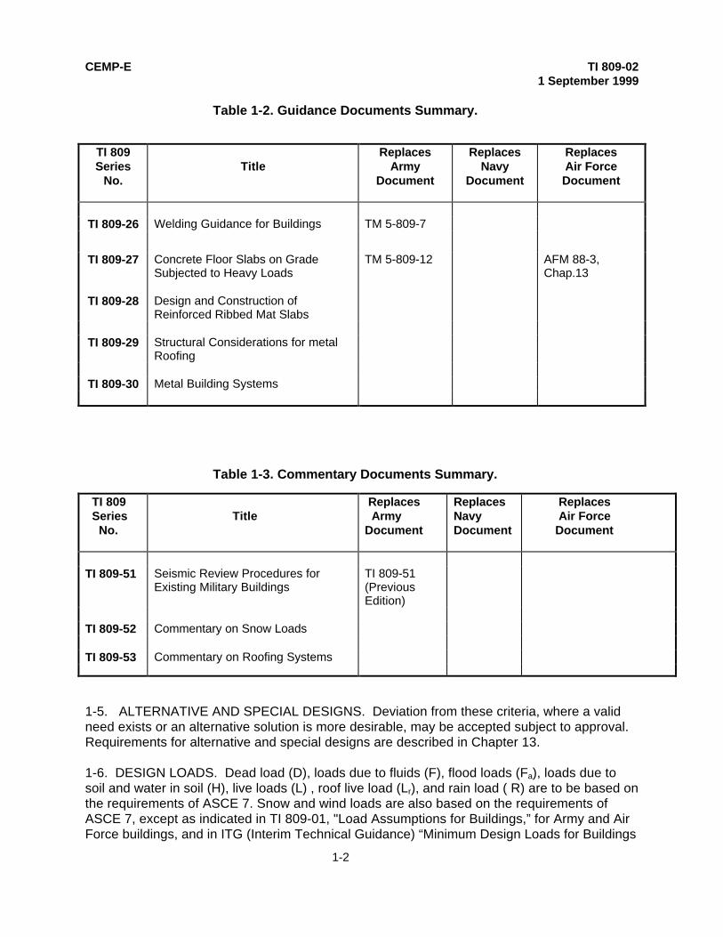
1-4. BACKGROUND. TI 809-02, "Structural Design Criteria for Buildings" is one in a series of TechnicalInstructions used to update the Army, Air Force, and Navy guidance requirements related to the designof buildings. The TI 809 Series documents are listed in Tables 1-1, 1-2, and 1-3. Where applicable theArmy, Navy, and Air Force guidance documents replaced by, or to be replaced by, the TI are indicated.In some instances the TI document listed in the table has not as yet been developed, or is currentlyunder development. In such cases, the appropriate Army, Navy, and Air Force guidance document willbe used until such time as the TI is published.
Table 1-1. Design Criteria Documents Summary.
TI 809Series
No.Title
ReplacesArmy
Document
ReplacesNavy Document
ReplacesAir ForceDocument
TI 809-01 Load Assumptions for Buildings TM 5-809-1 AFM 88-3, Chap. 1TI 809-02 Structural Design Criteria for Buildings TM 5-809-02 MIL-HDBK-1002/1
MIL-HDBK-1002/3MIL-HDBK-1002/5MIL-HDBK-1002/6DM 2.04
AFM 88-3, Chap. 2
TI 809-03 Structural Design Criteria for StructuresOther than Buildings
TI 809-04 Seismic Design for Buildings TM 5-809-10 NAVFAC, P-355 AFM 88-3, Chap.13
TM 5-809-10-1 NAVFAC, P-355.1 AFM 88-3,Chap.13,Sec. A
TI 809-05 Seismic Design for the Rehabilitationof Buildings
TM 5-809-10-2 NAVFAC, P-355-2 AFM 88-3,Chap. 3, Sec. B
TI 809-06 Masonry Design for Buildings TM 5-809-3 NAVFAC DM 2.9 AFM 8-3,Chapter 3
TI 809-07 Design of Load Bearing Cold-FormedSteel Systems and MasonryVeneer/Steel Stud Walls
CEMP-E TI 809-021 September 1999
1-2
Table 1-2. Guidance Documents Summary.
TI 809Series
No.Title
ReplacesArmy
Document
ReplacesNavy
Document
ReplacesAir ForceDocument
TI 809-26 Welding Guidance for Buildings TM 5-809-7
TI 809-27 Concrete Floor Slabs on GradeSubjected to Heavy Loads
TM 5-809-12 AFM 88-3,Chap.13
TI 809-28 Design and Construction ofReinforced Ribbed Mat Slabs
TI 809-29 Structural Considerations for metalRoofing
TI 809-30 Metal Building Systems
Table 1-3. Commentary Documents Summary.
TI 809 Series No.
Title Replaces ArmyDocument
ReplacesNavyDocument
Replaces Air Force Document
TI 809-51 Seismic Review Procedures forExisting Military Buildings
TI 809-51(PreviousEdition)
TI 809-52 Commentary on Snow Loads
TI 809-53 Commentary on Roofing Systems
1-5. ALTERNATIVE AND SPECIAL DESIGNS. Deviation from these criteria, where a validneed exists or an alternative solution is more desirable, may be accepted subject to approval.Requirements for alternative and special designs are described in Chapter 13.
1-6. DESIGN LOADS. Dead load (D), loads due to fluids (F), flood loads (Fa), loads due tosoil and water in soil (H), live loads (L) , roof live load (Lr), and rain load ( R) are to be based onthe requirements of ASCE 7. Snow and wind loads are also based on the requirements ofASCE 7, except as indicated in TI 809-01, "Load Assumptions for Buildings,” for Army and AirForce buildings, and in ITG (Interim Technical Guidance) “Minimum Design Loads for Buildings

CEMP-E TI 809-021 September 1999
1-3
and Other Structures” for NAVFAC buildings. Earthquake loads are based on therequirements of TI 809-04, "Seismic Design for Buildings," and FEMA 302, "NEHRPRecommended Provisions for Seismic Regulations for New Buildings and Other Structures."
1-7. COMBINATION OF LOAD EFFECTS. The effect on the structure and its componentsdue to gravity loads and seismic forces will be combined in accordance with the followingfactored load combinations, and in accordance with TI 809-04 guidelines:
1.2 D + 1.0 E +0.5 L + 0.2 S (ASCE 7, Paragraph 2.3.2)
0.9 D + 1.0 E (ASCE 7, Paragraph 2.3.2)
Where: D = dead loadE = earthquake load as defined by FEMA 302L = live load as defined by TI 809-01S = snow load as defined by TI 809-01
For the above load combinations the strength reduction factors (φ) for concrete will be inaccordance with Appendix C of ACI 318-95. All other load combinations (non-seismic loadcombinations) will be in accordance with the applicable material design standard (ACI 318 forconcrete, AISC for steel, etc.).
1-8. STRENGTH AND SERVICEABILITY PERFORMANCE OBJECTIVES. General require-ments with respect to strength and serviceability are indicated in the following paragraphs.Specific requirements on strength and serviceability with respect to the various types ofbuilding systems and construction materials are provided in the following chapters of the TI.
a. Strength. Buildings and other structures, and all parts thereof, will be designed tosupport safely the loads and load combinations indicated above.
b. Serviceability. Structural systems and members thereof will be designed to haveadequate stiffness to limit deflections, lateral drift, vibration, or any other deformations thatadversely affect the intended use and performance of the building. Building designs must alsoconsider deformation loads such as temperature, differential settlement, creep, and shrinkage.Measures necessary to keep buildings free from deformation load cracking and deterioration,such as crack control joints, will be considered an essential part of the building design. Inaddition buildings, when necessary, will be capable of withstanding severe environmentaleffects without incurring damage or deterioration that would reduce the building's service life.
c. Deflection and Drift Limits. Deflections of structural members will not be greater thanallowed by the applicable material standard (ACI, AISC, etc.). Deflection limits are needed torestrict damage to ceilings, partitions, and other fragile nonstructural elements. Therefore, thedeflection over span length (l) will not exceed that permitted by Table 1-4. Drift limits applicableto earthquake loading are provided in Table 6-1 TI 809-04. In certain cases, drift limits lowerthan those specified in TI 809-04 will be required to restrict damage to partitions, stair andshaft enclosures, glass, and other fragile nonstructural elements.

CEMP-E TI 809-021 September 1999
1-4
Table 1-4. Deflection Limits.(Adapted from the International Building Code (IBC)-Final Draft)
Construction LiveLoads
Snow orWindLoads
Dead +LiveLoad
Roof members Supporting plaster ceiling l / 360 l / 360 l / 240 Supporting Non-plasterceiling
l / 240 l / 240 l / 180
Not supporting Ceiling l / 180 l / 180 l / 120
Floor Members l / 360 ---------- l / 240
Exterior walls and interiorpartitions With brittle finishes l / 240 l / 240 ---------- With flexible finishes l / 120 l / 240 ----------
1-9. LOAD PATH CONTINUITY AND INTEGRITY.
a. General. Building designers must understand how the building will respond to verticaland lateral loads. Follow all loads through the structure to assure all the structural elementsand connections along the load path have sufficient strength and stiffness to maintainstructural integrity. Direct and continuous load paths from the roof to foundation must beprovided. Building configuration, continuous and redundant load paths, connection detailing,system ductility, quality of materials, and construction are important to building performance.These ancillary aspects of building design are covered in Chapter 2.
b. Structural Integrity. In accordance with ASCE 7, buildings and other structures will bedesigned to sustain local damage under extreme loading conditions with the structural systemas a whole remaining stable. This objective can be achieved by an arrangement of structuralelements which assures loads can be transferred from any locally damaged region to adjacentregions capable of resisting those loads. This can be accomplished by providing sufficientcontinuity, redundancy, and energy dissipating capability (ductility).
1-10. OVERSEAS CONSTRUCTION. Where local materials of grades other than thosereferenced herein are to be used, the working or yield stresses and details of construction willbe modified as required by the structural property characteristics of the local material. Thematerial, as far as practicable, will be of equivalent or better grade than the comparable gradesreferenced herein.
1-11. SERVICE LIFE. Service life of various buildings and facilities is defined as follows:a. Permanent construction. Permanent construction will be designed and constructed
to serve a life expectancy of 25 years or more, will be energy efficient, and will include finishes,materials, and systems selected for low maintenance and low life cycle costs.
CEMP-E TI 809-021 September 1999
1-5
b. Limited life structures. Limited life structures include both semi-permanent andtemporary construction as defined below.
(1) Semi-permanent construction will be designed and constructed to serve a lifeexpectancy of more than 5 years but less than 25-years (generally a 15-year service life), willbe energy efficient, and will include finishes, materials, and systems selected for a moderatedegree of maintenance using the life-cycle approach.
(2) Temporary construction will be designed and constructed to serve lifeexpectancy of 5 years or less, will use low cost construction, and systems selected withmaintenance factors being a secondary consideration.
1-12. STABILITY. The building foundation must be capable of safely transferring all verticaland horizontal forces, due to specified design load combinations, to the supporting soil or rock.The mechanism used for the transmission of horizontal forces may be friction between thebottom of the footing and ground, friction between the floor slab and ground, and /or lateralresistance of soil against vertical surfaces of grade beams, basement walls, footings, piles, orpile caps. Net upward forces on footings and piles, which must be resisted to preventoverturning and/or flotation, will be considered in the foundation design. Dead load shouldinclude the benefits of weight of the overlying fill in resisting sliding, overturning, and flotation.Structures will be designed to resist overturning effects caused by seismic forces inaccordance with TI 809-04. For load combinations other than earthquake when loadcombinations applicable to allowable stress design (ASCE 7, paragraph 2.4.1) are used for thefoundation design, the building will have a minimum safety factor of 1.5 against sliding,overturning, and flotation.
1-13. SPECIAL INSPECTIONS. Earthquake resistant structures designed in accordance withTI 809-04 and FEMA 302 are required to undergo special inspections. The term "specialinspection" means that experts qualified in the installation, fabrication, erection or placement ofstructural components and connections will be available on a periodic or continuous basis toensure the adequacy of the work. The type of special inspection depends on the type ofconstruction used (concrete, masonry, steel, etc.) and on the seismic region in which thebuilding is located. Special inspection requirements from FEMA 302 are addressed in thevarious chapters of this report. The requirements in some cases have been generalized tocover all types of loading conditions and combinations. Special inspections should not belimited to those required by FEMA 302 and this document. Rather they should be specificallyrequired in the contract documents where ever they are needed to assure quality inconstruction. It is the designers’ responsibility to assure all special inspection requirements areincluded in the contract specifications.

CEMP-E TI 809-021 September 1999
2-1
CHAPTER 2
BASIC STRUCTURAL SYSTEMS FOR BUILDINGS
2-1. SELECTION OF STRUCTURAL SYSTEM. The goals in the selection of a load resistingsystem are simplicity in the structural framing layout and symmetry in the structural systemreaction to design loadings. The selections must consider the need for economy, function, andreliability. Structural systems selected must have deformation characteristics that arecompatible with the architectural and other nonstructural building elements and features.Regular structure configuration, continuous and redundant load paths, and system ductility areattributes encouraged. These attributes are required of buildings constructed in high seismicareas.
2-2. COMMONLY USED STRUCTURAL SYSTEMS (Adapted from FEMA 178). The followingis a list of building systems commonly found in existing building construction. These systemsare provided for informational purposes with the understanding that not all the systems listed inthis paragraph are recommended for use in new building construction. Figures illustrating thetypes of construction described herein can be found in FEMA 154, "Rapid Visual Screening ofBuildings for Potential Seismic Hazards: A Handbook".
a. Building Type 1 - Wood, Light Frame. Light frame wood buildings are typically single,or multiple family dwellings of one or two stories. The essential structural character of this typeis repetitive framing by wood joists on wood studs. Loads are light and spans are small. Someof these buildings are engineered: however, most are not, but are constructed in accordancewith the International One and Two Family Dwelling Code. Shear walls are exterior wallssheathed with plank siding, stucco, plywood, gypsum board, particleboard, or fiberboard.Interior partitions are typically sheathed with gypsum board.
b. Building Type 2 - Wood, Commercial and Industrial. Commercial and industrial woodbuildings usually have floor areas in excess of 5000 square feet with few, if any, interior walls.The essential structural character is framing by beams on columns. The beams may be glulambeams, steel beams, or trusses. Lateral forces are resisted by wood, or metal diaphragms,and exterior walls sheathed with plywood, or particle board. The walls may have rod, or metalstrap bracing. Large openings for stores or garages often require post-and-beam framing.Lateral force resistance on walls with large openings can be achieved with steel frames ordiagonal bracing. Type 2 buildings have been used with some frequency in militaryconstruction, in particular with respect to child development centers.
c. Building Type 3 - Steel Moment Frame. These buildings have frames of steel columnsand beams. The beam-column connections are usually fully developed as a momentconnection to resist lateral forces. Lateral loads are transferred by diaphragms to the momentresisting frames. The diaphragms can be steel decking, reinforced concrete, or a composite ofsteel decking with a concrete topping slab. The frames develop their stiffness by full or partialmoment connections. The frames can be located almost anywhere in the building. Usually thecolumns have their strong directions orientated so that some columns act primarily in oneorthogonal direction while others act in the other orthogonal direction, and the frames consistof lines of strong columns and their intervening beams. Steel moment frame buildings are

CEMP-E TI 809-021 September 1999
2-2
typically more flexible than shear wall buildings, and their design is often controlled by driftlimitations.
d. Building Type 4 - Steel Braced Frame. Steel braced frame buildings are similar inconstruction to steel moment frame buildings except lateral resistance is provided by bracingrather than beam to column moment connections.
e. Building Type 5 - Steel Light Frame. Steel light frame buildings are typically pre-engineered and prefabricated with rigid frames in the transverse orthogonal direction. Theroofs and walls usually consist of lightweight metal panels. The frames are often designed formaximum efficiency, often with tapered beam and column sections built up of light plates. Theframes are built in segments and assembled in the field with bolted joints. Lateral loads in thetransverse direction are resisted by the rigid frames with loads distributed to them by the roofand wall panels. Lateral loads in the longitudinal direction are resisted by steel strap or rodbracing, or by shear panels located in the roof and walls.
f. Building Type 6 - Steel Frame with Concrete Shear Walls. These buildings are of typicalsteel frame construction with lateral loads resisted by cast-in-place reinforced concrete shearwalls. The steel frame is designed for vertical loads only. The shear walls may also serve asbearing walls carrying vertical loads that would otherwise be carried by steel columns. Thesteel frames may provide a secondary lateral force resisting system if the steel columns andbeams are rigidly connected as in Building Type 3. This combined system is termed a "dual"system in which the steel moment frames are designed to work together with the concreteshear walls with load sharing dependent on the stiffness of the two systems. In this case, thewalls would be evaluated as concrete shear walls, and the frames would be evaluated as steelmoment frames.
g. Building Type 7 - Steel Frame with Infill Shear Walls. In this older type of construction,some of which still remains, solidly infilled masonry panels act as a diagonal strut betweenmoment frames. This type of construction is not recommended, because if the infill walls donot fully engage the frame members (i.e., lie in the same plane), diagonal compression strutaction will not develop.
h. Building Type 8 - Concrete Moment Frame. These buildings are similar to steelmoment frame buildings except the frames are of reinforced concrete construction. In highseismic areas the concrete frames have large quantities of longitudinal and transversereinforcing steel, with closely spaced transverse steel (spiral reinforcement and stirrups)required to confine the concrete and produce a ductile response to earthquake ground motion.
i. Building Type 9 - Concrete Shear Walls. The vertical components of the lateral-forceresisting system in these buildings are concrete shear walls that are usually bearing walls.Buildings in which the shear wall area is relatively large with respect to the floor area, thereoften is no need to provide boundary elements to handle the large compressive strains thatcan occur in the wall extremities. Buildings with limited shear wall area will require shear wallboundary elements in accordance with ACI 318.
j. Building Type 10 - Concrete Frame with Infill Shear Walls. These buildings are similarto Type 7 buildings except that the frame is of reinforced concrete. The capacity of this system

CEMP-E TI 809-021 September 1999
2-3
during major earthquakes is often limited by the shear strength of the columns (non-ductileresponse) since once the infill cracks much of the shear is transferred to the columns. For thisreason the use of Type 10 buildings is not recommended for high seismic regions.
k. Building Type 11 - Precast/Tilt-Up Concrete Walls with Lightweight Flexible Diaphragm.These buildings often have a metal deck or wood roof diaphragms that distributes lateralforces to precast concrete shear walls. The connections between the diaphragms and wallsand between precast concrete wall elements are extremely important in high seismic regions.Tilt-up buildings often are more than one story.
l. Building Type 12 - Precast Concrete Frames with Concrete Shear Walls. Thesebuildings typically have floor and roof diaphragms composed of precast concrete elements withor without cast-in-place concrete topping slabs. In high seismic regions, cast-in-place concretetopping slabs are generally used unless diaphragm spans are very small. Precast concretegirders and columns support the diaphragms. The girders often bear on column corbels.Closure strips between precast floor elements and beam column joints usually are cast-in-place concrete. Welded steel inserts often are used to interconnect precast elements. Thecapacity of these type buildings to resist lateral loads is dependent on connection strength andductility. Buildings with precast frames and concrete shear walls should perform as intendedduring major earthquakes if the connections have sufficient strength and displacementcapacity.
m. Building Type 13 - Reinforced Masonry Bearing Walls with Metal Deck RoofDiaphragms. These buildings have perimeter bearing walls of reinforced concrete masonryunits (CMU) or reinforced brick construction. The bearing walls are also the vertical elementsof the lateral force resisting system. The roof diaphragm is of metal deck construction with orwithout a cast-in-place topping. Floor diaphragms are generally a reinforced concrete slab orprecast concrete slab supported by steel beams or CMU walls. The roof and floor diaphragmsshould have sufficient strength and stiffness to transfer lateral loads to the transverse shearwalls without imposing excessive out-of-plane displacements on the longitudinal walls.
n. Building Type 14 - Reinforced Masonry Walls with Precast Concrete Roof Diaphragm.These buildings are similar to Type 13 buildings except the roof diaphragm is composed ofinterconnected precast concrete elements such as planks, or tee beams with or without a cast-in-place topping. The roof diaphragm is stiffer than the metal deck diaphragm of the Type 13building and therefore roof diaphragm deflections will generally not impose excessivedisplacements on the longitudinal walls. Because of efflorescence problems double wytheconstruction with grout fill between wythes is not permitted for military buildings.
o. Building Type 15 - Unreinforced Masonry Bearing Wall Building. These buildings aresimilar in construction to Type 13 and Type 14 buildings except the masonry is unreinforced orhas the minimum reinforcement required by code. Unreinforced masonry construction is typicalin the eastern and mid-western United States. The performance of unreinforced masonrybuildings when subjected to earthquake ground motions has often been unsatisfactory. Forthis reason Type 15 building construction is not permitted by the Army and Air Force.

CEMP-E TI 809-021 September 1999
2-4
2-3. BUILDING SYSTEM USE IN MILITARY CONSTRUCTION. Various bearing wall systems,building frame systems, and moment resisting frame systems were described in the precedingparagraph. It should be noted that a particular building type (such as Type 9) might be eithera bearing wall system or a building frame system. Descriptions of systems commonly used inmilitary construction, and discussions of particular systems that should be avoided, arepresented in the following paragraphs.
a. Bearing Wall Systems. A bearing wall system is a structural system without acomplete vertical load carrying space frame. Bearing walls or bracing systems support gravityloads. Shear walls or braced frames resist lateral loads. Bearing wall systems of reinforcedconcrete and reinforced masonry (Types 9, 11, 12, 13, and 14) are common to all types ofmilitary construction. Bearing wall systems of steel construction (Types 4 and 6) are alsocommon.
b. Building Frame Systems. A building frame system is a structural system with anessentially complete space frame that supports gravity loads. Shear walls or braced framesresist lateral loads. Building frame systems in which non-load bearing shear walls or bracedframes resist lateral loads (Types 4, 6, 9, 11, and 12 buildings) are excellent systems for highseismic regions and are commonly used in military construction.
c. Moment Frame Systems. A moment resisting frame system is a structural system withan essentially complete space frame that supports gravity loads and resists lateral wind andearthquake forces. Moment resisting frame systems of steel and concrete (Types 3, and 8buildings) are sometimes used. Moment frames are recommended in cases where it isundesirable to restrict the interior of the building with interior bracing or shear walls. Interstorydrift is a problem with moment frame construction and the interaction of the moment frameswith architectural and other nonstructural building elements must be considered.
d. Other Systems. Because of fire protection concerns, systems of wood construction(Type 1 and Type 2 buildings) are generally limited to residential construction. Although, in thewestern United States it is not uncommon to find wood construction used for the constructionof one and two story office buildings, school buildings, and commercial buildings. Steel lightframe (Type 5) buildings are often used for industrial type buildings, and for one and two storydormitory construction. Infill systems (Type 7, and 8 buildings) although commonly used inolder construction, are not recommended for new military buildings because of undesirableinteraction that occurs between the infill walls and the frames when the building is subjected tolateral loads. Infill wall systems are particularly undesirable in high seismic regions.
2-4. CHARACTERISTICS IMPORTANT TO BUILDING PERFORMANCE. (Adapted from DOE"Design and Evaluation Guidelines for Department of Energy Facilities Subjected to NaturalPhenomena Hazards") Proper design and detailing of structural systems and their connectionsis critical. Structural engineers should work closely with the building architect in the earlyphases of building design to assure characteristics important to building performance such asstructural system configuration, load path continuity, redundancy, ductility, and the quality ofmaterials and construction, become a integral part of the concept design.
a. System Configuration. The configuration of the structural system is important.Irregularly configured structures under extreme loading conditions, especially earthquake

CEMP-E TI 809-021 September 1999
2-5
loadings, experience greater damage than regularly configured systems. Irregular structuresare structures having one or more plan irregularities or one or more vertical irregularities. Planirregularities are defined in FEMA 302, Table 5.2.3.2. Vertical irregularities are described inFEMA 302, Table 5.2.3.3. Plan irregularities, such as large reentrant corners or differences instiffness between portions of diaphragms, produce stress concentrations and high localizedforces. Other plan irregularities can cause an undesirable torsional response to lateral loads.Buildings that are T, L, U-shaped, or cruciform configurations are examples of irregular plans.Often seismic joints, which separate the various wings of buildings, are provided to allow eachwing to perform as an individual structure. This is often more practical than using a rigorousthree-dimensional analysis to determine how the wings of the building will interact if connectedtogether. Vertical irregularities, such as an abrupt change in stiffness from one story to thenext, or offsets in the lateral force resisting systems from one story to the next, can alsoproduce stress concentrations and high-localized forces. Regular structural systemconfiguration should be encouraged for new designs, especially for buildings located in highseismic areas. It should be realized however that an regular configuration is not alwayspossible. In such cases the designer must recognize the effect each particular irregularity willhave on structural response and make a conscious effort to ensure his design will meet allstrength and serviceability requirements.
b. Load Path Continuity. Direct and continuous load paths should be provided to assurethat all loads to which the structure is subjected can be delivered from the load point ofapplication to the foundation. All elements and connections along the load path must havesufficient strength, stiffness, and deformation capability to deliver the loads to the foundationwithout impairing the buildings ability to perform as a unit. When connection is required todevelop the strength of the connected members (such as in the design of earthquake-resistantsystems), the effect member over-strength will have on system performance must beconsidered. Different parts of the building should be adequately interconnected to resistextreme loads, to prevent progressive type failures, and resist foundation settlement. Beamsand girders should be adequately tied to columns, and columns should be adequately tied tofootings. Concrete and masonry walls should be adequately anchored to floors and roofs forlateral support. Diaphragms that distribute lateral loads to vertical resisting elements must beadequately tied to those elements. Collector or drag struts should be provided to collect shearforces and deliver them to shear-resisting elements, such as shear walls or other bracingelements, that may be spaced at various intervals around the diaphragm. Shear walls must beadequately tied to floor and roof slabs and to footings. Non-structural elements such asexterior cladding and interior stairs should be isolated from structural load paths to assureloads are delivered as intended from the point of application to the foundation. Rigid non-structural features if not properly isolated can attract loads that will most likely damage non-structural elements and in the process create unintended load paths that can damagestructural elements.
c. Redundancy. Redundancy of load paths is a desirable structural systemcharacteristic, especially with respect to earthquake-resistant design. Redundancy means thatwhen one structural element or system fails a new load path develops allowing the loads oncecarried by the failed structural element or system to be safely transferred to another primary orsecondary system thereby preventing progressive collapse of the structure. Redundantsystems if properly designed will also prevent the formation of unwanted load paths. Forinstance if two or more bays of lateral bracing are provided on each side of a building the

CEMP-E TI 809-021 September 1999
2-6
failure of one bay of bracing will not cause a serious torsional response which could jeopardizethe bracing on the other sides of the building. A single row of bracing could be considered tohave redundant characteristics if each bracing element is designed to carry both tension andcompressive loads. This is not, however, as reliable as a system containing two or morebraced bays. The practice of limiting the bracing on a side of a building to a single bay shouldbe avoided if possible. A single braced bay consisting of tension-only bracing is unacceptable.In a building without redundant components, every component must function as intended topreserve the overall structural integrity of the building.
d. Ductility. It is desirable, and required by code, that structures be ductile to avoid brittlefailure mechanisms which could lead to an unexpected failure. Ductility is imperative for thedesign of earthquake resistant structures.
(1) Structural steel is an inherently ductile material. The ductility of steel structures isachieved by designing connections to avoid tearing or fracture and by ensuring an adequatepath for loads to travel across the connection. Detailing for adequate stiffness and restraint ofcompressive braces, outstanding legs of members, compression flanges, etc. must beprovided to avoid local and global instability by buckling of relatively slender steel membersacting in compression. Deflections must be limited to prevent overall frame instability due to P-∆ effects. Steel bracing systems must be configured such that bracing forces can not distortcolumns in a manner that would amplify P-∆ effects Refer to TI 809-04 for additionalinformation on acceptable and unacceptable bracing systems).
(2) Less ductile materials, such as concrete and unit-masonry, require steelreinforcement to provide ductility. Concrete structures should be designed to prevent brittlefailure mechanisms such as compressive failure, shear failure, anchorage failure, and bondfailures from occurring. Compressive failures in flexural members can be controlled by limitingthe amount of tensile reinforcement or by providing compressive reinforcement and confiningthe reinforcement with closely spaced transverse reinforcement such as spirals, or stirrup ties.Confinement increases the strain capacity and the compressive, shear and bond strengths ofconcrete and masonry. Shear failures in concrete and masonry can be prevented through theuse of adequate shear reinforcing. Anchorage and splice failures can be controlled byproviding adequate splice development length, or by providing suitable mechanical or weldedconnections. Masonry walls must be adequately reinforced and anchored to floors and roofs.Additional information on the detailing of structures to provide a ductile response to earthquakeground motions can be found in TI 809-04.
e. Quality of Materials and Construction. It has been observed that the quality ofmaterials used in construction and the quality of construction are important factors, which candetermine whether or not a building will survive extreme loadings due to earthquakes or wind.Testing and inspection programs are necessary to ensure the finished structure meets coderequirements. It is the designer’s responsibility to assure all testing and special inspectionsrequired by code are part of the contact documents.

CEMP-E TI 809-021 September 1999
3-1
CHAPTER 3
FOUNDATIONS
3-1. GENERAL. This chapter prescribes criteria for the design of building foundationsincluding spread footings, pile supported foundations, pier supported foundations, andmachinery foundations.
3-2. DESIGN. Allowable bearing pressures and allowable stresses where required in thedesign of pile and pier foundations will be used with the allowable stress design loadcombinations of ASCE 7. Where foundations are designed for seismic overturning using thestrength design load combinations of ASCE 7, the seismic overturning moment need notexceed 75% of the value determined by either the equivalent lateral force method, or themodal analysis method of TI 809-04, "Seismic Design for Buildings".
3-3. FOUNDATION AND SOILS INVESTIGATIONS. Foundation and soils investigationswhen required will be in accordance with EM 1110-1-1804, " Geotechnical Investigations".Additional information on foundation investigations can be found in the Navy Design Manual(DM) 7.1, "Soil Mechanics", and Military Handbook (MIL-HDBK) 1007/3, "Soil Dynamics andSpecial Design Aspects". The latter document describes the requirements for site specificstudies for seismically active areas. Pile and pier foundations will be designed and installed onthe basis of a foundations investigation and pile load test when required.
3-4. ALLOWABLE LOAD BEARING VALUES AND LATERAL SLIDING RESISTANCE OFSOILS.
a. Allowable Bearing Pressures. Maximum allowable bearing pressures will be determinedfor soil foundations in accordance with EM 1110-2-1905, "Bearing Capacity of Soils", and forrock foundations in accordance with EM 1110-1-1908, "Rock Foundations". The presumptiveallowable bearing pressures for spread footing as provided in Table 4-8 of EM 1110-1-1905can be used with caution for spread footings supporting small or temporary structures. Designguidance for foundations can be found in TM 5-818-1 / AFM 88-3, Chapter 7, "Soils andGeology Procedures for Foundation Design of Buildings and Other Structures (ExceptHydraulic Structures)", and in Navy Design Manual (DM) 7.02, " Foundations and EarthStructures".
b. Lateral Sliding Resistance. The resistance of footings to lateral sliding will becalculated by combining shear frictional resistance (V tan φ) and lateral soil resistance,
where:V = vertical loadφ = Angle of internal friction
The lateral soil resistance will not exceed one-half the computed passive resistance.
c. Increases in Allowable Bearing Values. Allowable bearing pressures may be increasedby 1/3 for load combinations involving wind or earthquake.
CEMP-E TI 809-021 September 1999
3-2
3-5. FOOTINGS AND FOUNDATIONS. Footings and foundations will be built on undisturbedsoil or compacted fill material.
a. Frost Protection. The minimum design depth of building foundations to protectagainst frost penetration will be in accordance with Tables 1 and 2 of TI 809-01 "LoadAssumptions for Buildings". The minimum depth when not governed by frost protectionrequirements will be 300 mm (12 inches). The DOD Weather Manual (a Tri-Service document)provides additional information that can be used to determine frost depth penetration.
b. Design. Footings will be so designed that the allowable bearing capacity of the soil isnot exceeded and that differential settlement is minimized. The minimum width of footings willbe 300mm (12 inches). Footing design will be in accordance with TM 5-818-1 / AFM 88-3,Chapter 7, or Navy Design Manual (DM) 7.02, “Foundations and Earth Structures.” Footingdesign will also meet the requirements of ACI 318, except loads and load combinations will beper the requirements of Chapter 1.
c. Seismic Footing Ties. Where a building is assigned to Seismic Design Category D,E, or F, as defined in FEMA 302, "NEHRP Recommended Provisions for the Seismic Design ofNew Buildings and Other Structures," individual spread footings founded on soil will beinterconnected by ties in accordance with the provisions of FEMA 302 and TI 809-04, "SeismicDesign for Buildings."
d. Gable Bent Footing Ties. The gable bent type of moment frame requires a horizontalreaction force at the foundation to resist horizontal spreading. Because often it is unreliable tocount on the soil surrounding the footings to provide this reaction, (i.e., excavation next to thebuilding may reduce lateral bearing resistance), footing ties are advisable. These ties, mayconsist of reinforced concrete tension tie beams that are located below the slab-on-grade, orfor short span frames may be reinforcing steel which anchors the gable bent footing directly tothe slab-on-grade. When gable bent frames are anchored to the slab-on-grade it is imperativethat the location of the ties be coordinated with the slab-on-grade jointing to assure tie capacityis not reduced or impaired by the joints. Reinforced concrete tension tie beams are required forgable bent frames with spans of 15 meters (50 feet) or more.
e. Footings on Expansive Soils. Expansive soils change volume from changes in watercontent leading to total and differential foundation movements. Seasonal wetting and dryingcycles have caused soil movements that lead to long-term deterioration of structures. Soils canhave large strengths and bearing capacity when relatively dry. Expansive soils consist ofplastic clays and clay shales that often contain colloidal clay materials. They include marls,clayey siltstone, sandstone, and saprolites. Some of these soils, especially dry residual clayeysoil, may heave under low applied pressure but collapse under higher pressure. In certaincases, clay soils may not exhibit swelling characteristics if undisturbed. This same soil, whendried by manipulation and re-compacted at less than the initial moisture content, may exhibitsome swell. Other soils may collapse initially but heave later on. Estimates of the potentialheave of these soils are necessary for consideration of the foundation design. Informationregarding the design of foundations on expansive soils can be found in TM 5-818-1.Additional information on expansive soils can be found in EM 1110-1-1905 and Navy DesignManual (DM) 7.02.
CEMP-E TI 809-021 September 1999
3-3
3-6. DEEP FOUNDATIONS. Deep foundations such as piles or pier foundations are neededto transmit the load of a building through a material of poor bearing capacity, or to eliminatedifferential settlements. The choice of pile or pier type for a given foundation should be madeon the basis of a comparative study of cost, permanency, stability under vertical and horizontalloading, and the required method of installation. Additional information on pile and pierfoundations can be found in the publications listed in Appendix A.
a. Pile Foundations. Pile foundations can consist of concrete, wood, or steel elementseither driven or drilled into the ground. Piles are relatively slender in comparison to theirlength. Piles derive their load carrying capacity through skin friction, end bearing, or acombination of both. Two of the pile types common to building construction, along with theiradvantages and disadvantages, are described below. Design of pile foundations will complywith the provisions of EM 1110-2-2906, "Design of Pile Foundations," or Navy Design Manual(DM) 7.02, “Foundations and Earth Structures,” and Military Handbook (MIL-HDBK) 1007/3,“Soil Dynamics and Special Design Aspects.”
(1) Steel H-Piles. Steel H-piles are rolled steel sections with wide flanges so the depthof the section and widths of the flanges are about equal dimension. The cross-sectional areaand volume of the H-pile are relatively small; consequently, they can be driven throughcompacted granular materials and into soft rock. Steel H-piles because of their small volumedisplacement have little or no effect in causing ground swelling or rising of adjacent piles.Steel piles protruding above the ground lines are subject to corrosion at or somewhat belowthe ground line. Steel piles are ductile and therefore are suitable for use in high seismic areas.
(2) Prestressed Concrete Piles. Prestressed concrete piles are used and havereplaced for the most part the reinforced concrete precast pile. Some of its advantages areprestressing eliminates open cracks in a concrete pile, permits ease in handling, and reducesthe tendency to spall during driving. The compression induced in the pile permits piles tosustain considerable bending stresses. However when used in high seismic areas, prestressedconcrete piles must contain large quantities of confinement steel in the form of spiralreinforcement to resist the curvature demands place on the pile by differential subsurfaceground distortions. The transverse confinement reinforcement is similar to that required forreinforced concrete columns in high seismic areas (Site Class D, E, or F per TI 809-04).Information on the amounts of transverse reinforcement required for various regions of the pilecan be found in two PCI Journal Papers: "Seismic Design of Prestressed Concrete Piling" PCIJOURNAL, V.28, No. 2, March-April 1983, and "Simulated Seismic Load Tests on PrestressedConcrete Piles and Pile-Pile Cap Connections," PCI JOURNAL, V.35, No. 6, November-December 1990. The later PCI Journal Paper also provides valuable information on pile to pilecap connections.
b. Pier Foundations. Pier foundations are constructed by digging, drilling, or otherwiseexcavating a hole in the soil, which is subsequently filled with plain or reinforced concrete.Steel casings may or may not be used to facilitate pier construction. Two pier foundation typescommon to building construction, along with their advantages and disadvantages, aredescribed below. The design of pier foundations will follow the recommendations contained inACI Committee Report 336, "Suggested Design and Construction Procedures for PierFoundations."

CEMP-E TI 809-021 September 1999
3-4
(1) Augured Uncased Piers. Augured uncased pier foundations are constructed bydepositing concrete into an uncased augured hole. The drill hole diameter can range from 250mm (10-inches) to 1825 mm (72-inches), and up to 60 meters (200-feet) deep. In advancingthrough granular materials, drilling mud is often required to keep the hole open. The drilledshaft is filled with concrete in the dry, or by means of a tremie pipe through the drilling mud.When the concrete is to be reinforced, care and planning is required to assure thereinforcement can be placed in the desired location and to the depth required. For drilledpiers installed with a hollow stem auger, where longitudinal steel reinforcement is placedwithout lateral ties, the reinforcement will be placed through ducts in the auger prior to theplacement of concrete. When transverse reinforcement is required, the reinforcement isfabricated in cages which are securely tied so they will not rack or otherwise distort whenhandled and placed in the augured hole. Transverse confinement reinforcing similar to thatindicated for prestressed piling is required for uncased concrete piers constructed in highseismic areas.
(2) Drilled Shaft Piers. Drilled shaft piers can be generalized as large diameter cast-in-place concrete filled pipes. Pier diameter range from 300mm (12-inches) to 900 mm (36-inches), and the casing may, or may not remain part of the load-carrying element. Casingswhere used are usually thick-walled. Drilled shaft piers can be designed to carry extremelyheavy loads to extreme depths. Once installed to the desired depth, the pipe is cleaned,reinforcement placed, and filled with concrete if dry, or filled by the tremie method if water ispresent. The pipe can then either be pulled for reuse, or left in place to increase load carryingcapacity. Transverse confinement reinforcing similar to that indicated for prestressed piling isrequired for caisson piers constructed in high seismic areas in those cases where the pipe is tobe pulled. When the pipe is left in place, the pipe can be used to provide the necessaryconcrete confinement.
3-7. FOUNDATIONS FOR MACHINERY. Commonly used machines such as centrifugalpumps, fans, centrifuges, blowers, generator engines and compressors have vibrationalcharacteristics that can be damaging to foundations. The design of foundations supportingthese types of equipment requires special consideration to assure the equipment andfoundations supporting the equipment are not damaged due to resonant vibration. Informationand references pertaining to the design of foundations for vibratory loads can be found in theACI Committee 350 Report, "Environmental Engineering Concrete Structures". Additionalinformation can be found in ACI Committee 351 Report, " Foundations for Static Equipment,"and in Military Handbook (MIL-HDBK) 1007/3, “Soil Dynamics and Special Design Aspects.”
a. Minimum Requirements for Spread Footings Supporting Machinery. Machinery andgenerator foundations will be reinforced as required by design loads but in no case with lessthan 0.15 percent reinforcing each way distributed at top and bottom. Minimum bar size will beNo. 4, and maximum spacing of bars will be 300 mm (12 inches). These foundations will becompletely isolated from floor slab on grade with isolation joints. The allowable bearingpressure will be one-half that assumed for static load conditions. When the depth offoundation (D) is 900mm (36 inches) or more and its length-to-width (L /W) ratio is 3 or more,the following reinforcing steel requirements will be met.
(1) Longitudinal reinforcing will be distributed at top, bottom, and faces of foundationwithin 150 mm (6 inches) of the surface.

CEMP-E TI 809-021 September 1999
3-5
(2) Horizontal bars, bent and lapped to be continuous with side-wall, top and bottombars will be provided on end and side-wall faces. See Figure 3-1 for distribution ofreinforcement in heavy machinery foundations.
Figure 3-1. Machinery Foundation Reinforcing.
Foundation Outline
L
W
150 mm (6") Max. Bottom Reinforcement Shown(Top Similar)
PLAN
Top Reinforcement
Bottom Reinforcement
End Reinforcement
Side-wall Reinforcement
D
Section (At End or Side-wall)

CEMP-E TI 809-021 September 1999
3-6
3-8. SPECIAL INSPECTIONS.
• Pile and Pier Foundations. Inspectors familiar with pile and pier construction will bepresent when pile or pier foundations are being installed, and during load testing. Records areto be kept for each pile or pier installed, including the results of all load tests, and the final tipelevation.
CEMP-E TI 809-021 September 1999
4-1
CHAPTER 4
CONCRETE STRUCTURE DESIGN REQUIREMENTS
4-1. INTRODUCTION. This chapter prescribes criteria for the design of buildings using cast-in-place or precast construction with plain, reinforced, or prestressed concrete.
4-2. BASIS FOR DESIGN. The basis for design for buildings and building componentsconstructed of reinforced concrete, prestressed concrete, or plain concrete will be ACI 318,"Building Code Requirements for Structural Concrete and Commentary". Additional provisionsfor buildings constructed in severe environments, and buildings designed to resist the effectsof accidental explosions (blast-resistant construction) are provided in Chapter 12. In executingdesigns in accordance with ACI 318, cognizance will be given to ACI 318R; Portland CementAssociation (PCA) Notes on ACI 318 Building Code Requirements for Reinforced Concretewith Design Applications, and to ACI standards and committee reports referenced in thisdocument.
4-3. EARTHQUAKE RESISTANT DESIGN. Concrete structures are to be designed to resistthe effects of earthquake ground motions. The additional requirements of TI 809-04, "SeismicDesign for Buildings" and FEMA 302, "NEHRP Recommended Provisions for the SeismicDesign of New Buildings and Other Structures" will apply.
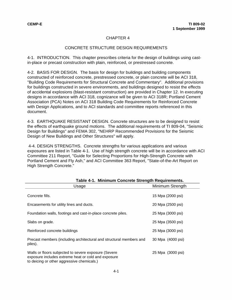
4-4. DESIGN STRENGTHS. Concrete strengths for various applications and variousexposures are listed in Table 4-1. Use of high strength concrete will be in accordance with ACICommittee 211 Report, "Guide for Selecting Proportions for High-Strength Concrete withPortland Cement and Fly Ash," and ACI Committee 363 Report, "State-of-the-Art Report onHigh Strength Concrete."
Table 4-1. Minimum Concrete Strength Requirements. Usage Minimum Strength
Concrete fills. 15 Mpa (2000 psi)
Encasements for utility lines and ducts. 20 Mpa (2500 psi)
Foundation walls, footings and cast-in-place concrete piles. 25 Mpa (3000 psi)
Slabs on grade. 25 Mpa (3500 psi)
Reinforced concrete buildings 25 Mpa (3000 psi)
Precast members (including architectural and structural members andpiles).
30 Mpa (4000 psi)
Walls or floors subjected to severe exposure (Severeexposure includes extreme heat or cold and exposureto deicing or other aggressive chemicals.)
25 Mpa (3000 psi)

CEMP-E TI 809-021 September 1999
4-2
Table 4-1. Continued
Concrete deposited under water (tremie concrete). 25 Mpa (3000 psi)
Columns in multistory buildings carrying heavy loads. 30 Mpa (4000 psi)
Reinforced concrete in contact with sea-water, alkaline soilsor waters, or other destructive agents.
30 Mpa (4000 psi)
Prestressed concrete construction. 35 Mpa (5000 psi )
4-5. DESIGN CHOICES. The selection of the structural concrete framing system, strength ofconcrete and reinforcement, conventional versus lightweight concrete, conventional versusprestressed design, and cast-in-place versus precast construction will be based on economicand functional considerations. Designers should take into account the specific type and sizeof structure, architectural features or special performance requirements, seismic exposure,construction cost factors for the building site, and the availability of materials and labor. Forfurther discussion of considerations in selecting appropriate composition and properties forconcrete, see ACI Committee 201 Report, "Guide to Durable Concrete."
4-6. SERVICEABILITY. Buildings must remain serviceable throughout their service life. Thismeans for concrete buildings and concrete structural elements, the concrete must be durable,free from objectionable cracking, and with adequate protection of the reinforcing steel toprevent corrosion. In additions, structural deflections that can damage interior partition walls,ceilings and various architectural features must be kept within acceptable limits.
a. Durability. Durability of Portland cement concrete is defined as its ability to resistweathering action, chemical attack, abrasion, or any other process of deterioration. Durableconcrete will retain its original form, quality, and serviceability when exposed to itsenvironment. Causes of concrete deterioration, such as freezing and thawing, aggressivechemical exposure, abrasion, corrosion of steel and other materials embedded in concrete,and chemical reactions of aggregates are described in the ACI Committee 201 Report, "Guideto Durable Concrete". This report also covers various preventive measures to assure durabilityproblems do not occur. The most significant causes of concrete deterioration are freezing andthawing, and corrosion of reinforcing steel.
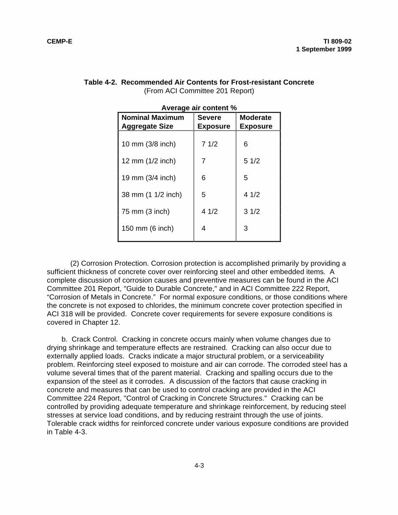
(1) Freeze-thaw Protection. Concrete made with good aggregates, low water-cementratio, and air entrainment will have good resistance to cyclic freezing. Air entrained concretewhich contains an appropriate distribution of air voids provides good freeze-thaw protection,because when the concrete freezes there is room for any water which has saturated theconcrete to expand without causing damage to the concrete. Table 4-2 providedrecommended air contents to prevent freeze-thaw damage.
CEMP-E TI 809-021 September 1999
4-3
Table 4-2. Recommended Air Contents for Frost-resistant Concrete(From ACI Committee 201 Report)
Average air content %Nominal MaximumAggregate Size
SevereExposure
ModerateExposure
10 mm (3/8 inch) 7 1/2 6
12 mm (1/2 inch) 7 5 1/2
19 mm (3/4 inch) 6 5
38 mm (1 1/2 inch) 5 4 1/2
75 mm (3 inch) 4 1/2 3 1/2
150 mm (6 inch) 4 3
(2) Corrosion Protection. Corrosion protection is accomplished primarily by providing asufficient thickness of concrete cover over reinforcing steel and other embedded items. Acomplete discussion of corrosion causes and preventive measures can be found in the ACICommittee 201 Report, "Guide to Durable Concrete," and in ACI Committee 222 Report,“Corrosion of Metals in Concrete.” For normal exposure conditions, or those conditions wherethe concrete is not exposed to chlorides, the minimum concrete cover protection specified inACI 318 will be provided. Concrete cover requirements for severe exposure conditions iscovered in Chapter 12.
b. Crack Control. Cracking in concrete occurs mainly when volume changes due todrying shrinkage and temperature effects are restrained. Cracking can also occur due toexternally applied loads. Cracks indicate a major structural problem, or a serviceabilityproblem. Reinforcing steel exposed to moisture and air can corrode. The corroded steel has avolume several times that of the parent material. Cracking and spalling occurs due to theexpansion of the steel as it corrodes. A discussion of the factors that cause cracking inconcrete and measures that can be used to control cracking are provided in the ACICommittee 224 Report, "Control of Cracking in Concrete Structures." Cracking can becontrolled by providing adequate temperature and shrinkage reinforcement, by reducing steelstresses at service load conditions, and by reducing restraint through the use of joints.Tolerable crack widths for reinforced concrete under various exposure conditions are providedin Table 4-3.

CEMP-E TI 809-021 September 1999
4-4
Table 4-3. Tolerable Crack Widths for Reinforced Concrete(From ACI Committee 224 Report)
Exposure Condition Tolerable Crack Width
Dry air or protective membrane 0.40 mm (0.016 inch)
Humidity, moist air, soil 0.30 mm (0.012 inch)
Deicing chemicals 0.20 mm (0.007 inch)
Sea water and saltwater spray 0.15 mm (0.006 inch)
Water retaining structures 0.10 mm (.004 inch)
(1) Shrinkage and Temperature Reinforcement. To keep cracks widths withinacceptable limits for buildings under normal exposure conditions the minimum shrinkage andtemperature reinforcement as required by ACI 318 will be provided. Shrinkage andtemperature steel requirements for buildings under severe exposure conditions are provided inChapter 12.
(2) Reducing Steel Stresses under Service Load Conditions. Cracking due to serviceloads can be controlled by limiting the maximum stress in the reinforcing steel, and byproviding small diameter bars at close spacing, rather than large size bars at wide spacing.Rules for distributing flexural reinforcement in beams and slabs to control flexural cracking areprovided in ACI 318. Suitable distribution of flexural reinforcement in beams and slabs ismeasured by a z-factor. Z-factors for normal interior and exterior exposure conditions willcomply with ACI 318 requirements.
(3) Joints and Joint Sealants. The effects of deflection, creep, shrinkage, temperaturecontraction and expansion, and the need for vibration isolation will all be addressed whendetermining the location of expansion and contraction joints in concrete buildings. Appropriateallowances for the aforementioned effects will be included in the design; location, details orprovisions for required contraction joints, control (weakened-plane) joints, expansions joints,isolation joints, and seismic joints. The location of expansion, contraction, and seismic jointswill be shown on the drawings since joints are critical with respect to other designconsiderations, e.g., configuration of the structural concrete, effects of joints on structuralstrength and shrinkage cracking, and the appearance of joint lines on exposed concretesurfaces. Where reinforced concrete foundation walls support masonry, crack controlmeasures will be designed to be compatible with crack control measures in the masonry. Allcrack control joints in the foundation wall will be carried upward into masonry crack controljoints. The following are basic

CEMP-E TI 809-021 September 1999
4-5
requirements for the more common types. Additional information on joints for concretebuildings can be found in ACI Committee 224.3 Report, "Joints in Concrete Construction," andthe Portland Cement Association Report (PCA), "Building Movements and Joints".
(a) Expansion Joints. Expansion joints are seldom needed in buildings less than 200feet in length, the exception being for brick masonry construction where expansion joints areprovided at close intervals. The maximum permitted spacing of expansion joints in brick wallsare provided in TI 809-06, “Masonry Structural Design for Buildings”. The maximum length abuilding can be without expansion joints depends on the temperature change that can occur inthe region in which the building is located. In general, expansion joints should be provided inaccordance with the following rules:
• Where the temperature differential (TD), defined as the greater of the differencesbetween the annual mean air temperature and the highest and lowest air temperature to beexpected, is not greater than 20 degrees C (70 degrees F) and no excessive change inatmospheric moisture is anticipated, expansion joints should be spaced so straight lengthsof building measure no more than 90 meters (300 feet) between joints.
• Where the TD is greater than 20 degrees C (70 degrees F), or where excessive changein atmospheric moisture is likely, expansion joints should be spaced so straight lengths ofbuilding measure no more than 60 meters (200 feet) between joints.
• An expansion (or seismic) joint is usually required between adjoining building areaswhich are different in shape, or between areas where different rates of building settlementare anticipated.
• Joints for structural or seismic reasons are often located at junctions in L-, T-, or U-shaped buildings.
Expansion joints should extend entirely through the building, completely separating it intoindependent units. Column footings located at expansion joints need not be cut throughunless differential settlements or other foundation movements are anticipated. Expansionjoints should be carried down through foundation walls: otherwise the restraining influence ofthe wall below grade, without a joint, may cause the wall above to crack in spite of it's joint.Reinforcement must never pass through an expansion joint. An empirical approach fordetermining the need for expansion joints is provided in the PCA Report, "Building Movementsand Joints".
(b) Control Joints. Control joints are needed to eliminate unsightly cracks in exposedbuilding walls by controlling the location in which cracking due to volume change effects takesplace. As a general rule:
• In walls with openings, space control joints at 6-meter (20-foot) intervals; in walls withinfrequent openings, space at 8-meter (25-foot) intervals.
• Provide a control joint within 3 to 5 meters (10 or 15) feet of a corner.

CEMP-E TI 809-021 September 1999
4-6
• Where steel columns are embedded in the walls, provide joints in the plane of thecolumns.
• If the columns are more than 8 meters (25 feet) apart, provide intermediate joints.Numerous ways have been developed for forming control joints in walls. Whatever method isused, the thickness of the wall section at the joint should be reduced at least 20% by the depthof the joint; and the sum of the depths of the inside and outside grooves should not be lessthan 50 mm (2 inches).
(c) Construction Joints. Construction joints are used to allow concrete placement ofseparate construction elements at different times, e.g., between columns and beams, footingsand pedestals, etc. Construction joints will be made with tie bars, dowels, or keys to provideshear transfer. The location and details of critical construction joints will be shown on thedrawings and, to the extent practicable, will coincide with the location of expansion or controljoints. The location of other construction joints need not be shown. Cautionary and advisorynotes regarding acceptable joint locations will be included on the drawings.
(d) Seismic Joints. Buildings that are irregular in plan such as T, L, U, or cruciformshaped buildings can generate high torsional or twisting effects when subjected to earthquakeground motions. These structures would require a three-dimensional analysis for a rigorousdetermination of stress distribution. Since such analyses are generally not practical, seismicjoints are provided to separate various blocks of the structure into regular shaped units that willnot exhibit a torsional response. The joints should be of sufficient width to prevent hammeringon adjacent blocks during earthquakes, and should be adequately sealed to protect thestructure from the environment.
(e) Sealing joints. Exterior expansion, control, and construction joints should be sealedagainst moisture penetration using methods such as waterstops or sealants as appropriate forthe prevailing conditions.
4-7. LOAD PATH INTEGRITY. Loads must be transferred from their point of application to thefoundation. All structural elements and connections along the load path must have sufficientstrength, and in the case of seismic resistant structures, sufficient ductility to transfer the loadsin a manner that will not impair structural performance. Most load path deficiencies are a resultof inadequate connections between precast elements, or between cast-in-place concreteelements and precast elements. Connections are often required to:
• Transfer shear from floor and roof diaphragms to the walls
• Transfer shear from the walls to the foundations
• Transfer shear between individual wall panels
• Transfer tension caused by overturning forces

CEMP-E TI 809-021 September 1999
4-7
• Transfer shear, bending, and axial loads between beams and columns andbetween beams and walls.
Connections between precast elements, or between cast-in-place concrete elements andprecast elements can include the following types of connections:
• Column to foundation• Column to column• beam to column• Slab to beam• Beam to girder• Beam to beam• Slab to slab• Wall to foundation• Slab to wall• Beam to wall• Wall to wall
Details for these various types of connection can be found in the Prestressed ConcreteInstitute (PCI) Technical Report No. 2, "Connections for Precast Prestressed ConcreteBuildings".
a. Shear Connections. Shear connections are classified as either "wet" or "dry". Wetconnections use reinforced or unreinforced cast-in-place concrete to form the junction betweenmembers. Dry connections utilize a mechanical anchor, such as bolts or welded metal, totransfer load. Wet and dry connections use shear-friction resistance to transfer forces. In wetconnections the reinforcing steel placed across the potential failure plane provides theclamping force needed to provide the shear-friction resistance. The most common type of dryconnection involves embedded plates or other structural steel shapes that are anchored to theconcrete by welded studs, anchor bolts, or expansion anchors. The embedded plates orstructural steel shapes embedded in each of the concrete elements to be connected, are thenconnected themselves by weldments or by bolting. Contractors prefer the “dry” typeconnections because they are the easiest types to construct. The "wet" type connectorshowever are usually the best performers, especially under cyclic loading conditions such asoccur during earthquakes.
b. Embedded Bolt and Headed Stud Anchors. Embedded anchor bolts and headedstuds are commonly used to transfer shear and tension loads between cast-in-place concreteand precast concrete members and between cast-in-place concrete and structural steelshapes. Anchor connections should be designed and detailed to assure connection failure willbe initiated by failure of the anchor steel rather than by failure of the surrounding concrete. Thedesign of anchor bolt connectors will be based on the requirements of FEMA 302, Paragraph9.2, "Bolts and Headed Anchors in Concrete." Additional information regarding the use ofheaded anchor bolts for anchorage can be found in the American Institute of SteelConstruction (AISC) Engineering Journal, Second Quarter / 1983 Report, "Design of HeadedAnchor Bolts," and in the Prestressed Concrete Institute (PCI) Design Handbook. Where

CEMP-E TI 809-021 September 1999
4-8
strength design is used, the required strength, and the design of the anchors will be inaccordance with FEMA 302. When allowable stress design (ASD) is used, the allowableservice load for headed anchors in shear or tension, assuming the anchor bolts conform toASTM 307 or an approved equivalent can be assumed equal to that indicated in Table 4-4.For ASD design, when anchors are subject to combined shear and tension, the followingrelationship will be used:
P
P
V
Vs
t
s
t
+
≤
5 3 5 3
1
/ /
Where:
Ps = applied tension service load
Pt = allowable tension service load from Table 4-4
Vs = applied shear service load
Vt = allowable shear service load from Table 4-4
The allowable service loads in tension and shear specified in Table 4-4 are for the edgedistances and spacing specified. The edge distance and spacing can be reduced to 50percent of the values specified with an equal reduction in allowable service load. Where edgedistance and spacing are reduced less than 50 percent, the allowable service load will bedetermined by linear interpolation. Increase of the values in Table 4-4 by one-third is permittedfor load cases involving wind or earthquake. Where special inspection is provided for theinstallation of anchors, a 100 percent increase in the allowable tension values of Table 4-4 ispermitted. No increase in shear value is permitted.
c. Expansion Anchors. Expansion anchors will be designed in accordance with theprovisions of ACI Committee 449 Report, "Concrete Nuclear Structures," Appendix B, "SteelEmbedments." The engineer will review expansion anchor design features, failure modes, testresults and installation procedures prior to selecting a specific expansion anchor for anapplication. Expansion anchors will not be used to resist vibratory loads in tension zones ofconcrete members unless tests are conducted to verify the adequacy of the specific anchorand application. Expansion anchors will not be installed in concrete where there is obvioussigns or cracking, or deterioration.
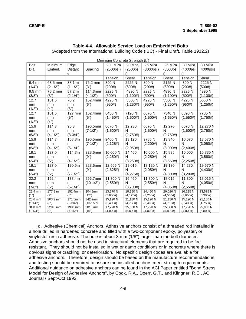
CEMP-E TI 809-021 September 1999
4-9
Table 4-4. Allowable Service Load on Embedded Bolts(Adapted from the International Building Code (IBC) - Final Draft, Table 1912.2)
Minimum Concrete Strength (fc')
BoltDia.
MinimumEmbed.
EdgeDistance
Spacing 20 MPa(2500psi)
20 Mpa(2500psi)
25 MPa(3000psi)
25 MPa(3000psi)
30 MPa(4000psi)
30 MPa(4000psi)
Tension Shear Tension Shear Tension Shear6.4 mm(1/4")
63.5 mm(2-1/2")
38.1 m(1-1/2")
76.2 mm(3")
890 N(200#)
2225 N(500#)
890 N(200#)
2125 N(500#)
390 N(200#)
2225 N(500#)
9.5 mm(3/8")
76.2 mm(3")
57.2 m(2-1/4")
114.3mm(4-1/2")
2225 N(500#)
4890 N(1,100#)
2225 N(500#)
4890 N(1,100#)
2225 N(500#)
4890 N(1,100#)
12.7mm(1/2")
101.6mm(4")
76.2mm(3")
152.4mm(6")
4225 N(950#)
5560 N(1,250#)
4225 N(950#)
5560 N(1,250#)
4225 N(950#)
5560 N(1,250#)
12.7mm(1/2")
101.6mm(4")
127 mm(5")
152.4mm(6")
6450 N(1,450#)
7120 N(1,600#)
6670 N(1,500#)
7340 N(1,650#)
6890 N(1,550#)
7785 N(1,750#)
15.9mm(5/8")
114.3mm(4-1/2")
95.3mm(3-3/4")
190.5mm(7-1/2")
6670 N(1,500#)
12,230N(2,750#)
6670 N(1,500#)
12,270N(2,750#)
6670 N(1,500#)
12,270 N(2,750#)
15.9mm(5/8")
114.3mm(4-1/2")
158.8mm(6-1/4")
190.5mm(7-1/2")
9460 N(2,125#)
13,120N(2,950#)
9785 N(2,200#)
13,340N(3,000#)
10,670N(2,400#)
13,570 N(3,050#)
19.1mm(3/4")
127.0mm(5")
114.3mm(4-1/2")
228.6mm(9")
10,000 N(2,250#)
14,460N(3,250#)
10,000 N(2,250#)
15,835N(3,560#)
10,000N(2,250#)
15,835 N(3,560#)
19.1mm(3/4")
127.0mm(5")
190.5mm(7-1/2")
228.6mm(9")
12,565 N(2,825#)
19,015N(4,275#)
13,120 N(2,950#)
19,130N(4,300#)
14,230N(3,200#)
19,570 N(4,400#)
22.2mm(7/8")
152.4mm(6")
133.4mm(5-1/4")
266.7mm(10-1/2")
11,300 N(2.550#)
16,460N(3,700#)
11,300 N(2,550#)
18,015N(4,050#)
11,300N(2,550#)
18,015 N(4,050#)
25.4 mm(1")
177.8 mm(7")
152.4mm(6")
304.8mm(12")
13,570 N(3.050#)
18,350 N(4,125#)
14,460 N(3,250#)
20.020 N(4,500#)
16,235 N(3,650#)
23,575 N(5,300#)
28.6 mm(1 1/8")
203.2 mm(8")
171.5mm(6-3/4")
342.9mm(13-1/2")
15,120 N(3,400#)
21,130 N(4,750#)
15,120 N(3,400#)
21,130 N(4,750#)
15,120 N(3,400#)
21,130 N(4,750#)
31.8 mm(1 1/4")
228.6 mm(9")
190.5mm(7-1/2")
381.0mm(15")
17,790 N(4,000#)
25,800 N(5,800#)
17,790 N(4,000#)
25,800 N(5,800#)
17,790 N(4,000#)
25,800 N(5,800#)
d. Adhesive (Chemical) Anchors. Adhesive anchors consist of a threaded rod installed ina hole drilled in hardened concrete and filled with a two-component epoxy, polyester, orvinylester resin adhesive. The hole is about 3 mm (1/8") larger than the bolt diameter.Adhesive anchors should not be used in structural elements that are required to be fireresistant. They should not be installed in wet or damp conditions or in concrete where there isobvious signs or cracking, or deterioration. No specific design codes are available foradhesive anchors. Therefore, design should be based on the manufacture recommendations,and testing should be required to assure the installed anchors meet strength requirements.Additional guidance on adhesive anchors can be found in the ACI Paper entitled "Bond StressModel for Design of Adhesive Anchors", by Cook, R.A., Doerr, G.T., and Klingner, R.E., ACIJournal / Sept-Oct 1993.

CEMP-E TI 809-021 September 1999
4-10
e. Other Steel Embedments. Other steel embedments will be designed in accordancewith the provisions of ACI Committee 449 Report, "Concrete Nuclear Structures," Appendix B,"Steel Embedments."
f. Special Considerations.
(1) Shear Transfer. The analysis of shear transfer will be in accordance withprovisions of ACI 318. Special attention will be given to transfer of shear at locations such asshear heads, bases of walls, brackets and corbels.
(2) Compatibility. The combined action of flexible and rigid shear connectors will not beconsidered as providing simultaneous shear transfer. Rigid shear connectors includeroughened surfaces and structural shapes. Flexible connectors include bolts, stirrups, dowelbars, and ties.
(3) Mechanical Anchorage of Reinforcing Steel. Mechanical connections are permittedfor reinforcing steel in accordance with the provisions of ACI 318. There are many applicationsthat make the use of mechanical connections feasible or more practical. Information on thetypes of mechanical connectors, their use, and design requirements can be found in the ACICommittee 439 Report, "Mechanical Connections of Reinforcing Bars".
4-8. DETAILING REQUIREMENTS. Details and detailing of concrete reinforcement willconform to ACI 315, "Details and Detailing of Concrete Reinforcement". Engineering andplacing drawings for reinforced concrete structures will conform to ACI 315R, "Manual ofEngineering and Placing Drawings for Reinforced Structures". For seismic areas, the designand details will conform to TI 809-04, "Seismic Design for Buildings".
4-9. SPECIAL INSPECTIONS.
• Periodic special inspection during and upon completion of the placement ofreinforcing steel in intermediate moment frames, in special moment frames, and in shearwalls is required.
• Continuous special inspection during the welding of reinforcing steel for structuralmembers is required. • Periodic special inspection during and upon completion of the placement concrete inintermediate moment frames, in special moment frames, and in shear walls is required. • Periodic special inspection is required during the placement and after completion ofplacement of prestressing steel, and continuous special inspection is required during allstressing and grouting operations and during the placement of concrete.
• Periodic special inspection is required during the placement of anchor bolts,expansion anchors, and chemically grouted anchors to verify the anchor system is inconformance with approved plans and specifications.

CEMP-E TI 809-021 September 1999
5-1
CHAPTER 5
SLABS ON GRADE
5-1. INTRODUCTION. This chapter provides design and construction requirements forindustrial type (non-residential) lightly loaded slabs on grade. Industrial type slabs refer tothose slabs that are reinforced to minimize the number of crack control joints (maximize jointspacing), Guidance for unreinforced residential type concrete slabs, which utilize crack controljoints spaced at frequent intervals to minimize cracking, can be found in the PCA Publication,"Concrete Floors on Ground." Lightly loaded slabs on grade are those supporting stationarylive loads of not more than 20 kPa (400 pounds per square foot), stationary concentrated line(wall) loads of not more than 15 kPa (300 pounds per foot), or vehicle axle loads of not morethan 2275 kg (5000 pounds). The guidance is applicable to usual exposure conditionsmeaning interior locations other than airplane hangars where slabs are not subject to extremeclimatic changes, and to typical subgrade conditions characterized by sufficient underdrainageto prevent frost penetration, the absence of a wet environment, i.e., volume change due tochange in moisture content is limited, and the absence of expansive soils. In addition, typicalsubgrade conditions are deemed to include only soils classified according to ASTM D 2487,"Classification of Soils for Engineering Purposes," as either Class ML, any of the S or Ggroups, or Class CH, CM, or CL having a modulus of subgrade reaction (k) of 2.75 kg percubic centimeter (100 pounds per cubic inch) or greater. Although slabs on grade may bedesigned to perform satisfactorily on subgrades of lower strength, design for such conditions isbeyond the scope of this manual. Refer to TI 809-27, "Concrete Floor Slabs on GradeSubjected to Heavy Loads," for the design of slabs on grade subjected to heavy loads, and toTI 809-28, "Design and Construction of Reinforced Ribbed Mat Slab" for the design of acommonly used slab-on-grade system for resisting potential foundation movements at sitescontaining expansive soils. Additional information on the design of slabs on grade, primarilyindustrial floors, can be found in ACI Committee 360 Report, “Design of Slabs on Grade.”
5-2. BASIS FOR DESIGN.
a. General. Slabs-on-grade will be designed for bending stresses due to uniform loadsand concentrated loads and for in-plane stresses due to drying shrinkage and subgrade dragresistance. When appropriate for the type facility being designed, slabs will be designed forthe effects of warehouse loadings involving aisles, posts and racks, etc. In such instances,particular attention will be given to the design for negative moment in aisles.
b. Guidance. Proper construction methods, workmanship, and concrete mixproportioning will follow the guidelines of ACI Committee 302 Report, "Guide to Concrete Floorand Slab Construction". Slabs are required to have a minimum thickness of 100 mm (4inches). The following thickness for maximum uniform design live loads will be used providedthe modulus of subgrade reaction (k) is at least 2.75 kg per cubic centimeter (100 pounds percubic inch).

CEMP-E TI 809-021 September 1999
5-2
Thicknessof Slab
MaximumUniformDesign Live Load
100 mm (4” ) 7 Kpa (150 psf)150 mm (5”) 12 Kpa (250 psf)200 mm (6”) 20 Kpa (400 psf)
Unless otherwise specified above, the correct slab thickness will be determined in accordancewith the Portland Cement Association (PCA) Publication entitled, "Slab Thickness Design forIndustrial Concrete Floors on Grade." In the PCA design process compressive strength isconverted to modulus of rupture, which is then reduced by a factor of safety to obtain themaximum allowable flexural tensile stress. The maximum allowable flexural tensile stress isthen used to find the required slab thickness. For typical values of modulus of subgradereaction refer to TI 809-27, "Concrete Floor Slabs on Grade Subjected to Heavy Loads." Whenwall loads exceed 15 kPa (300 lb./foot) slabs-on grade will be thickened in accordance withthe provisions of TI 809-27.
5-3. SERVICEABILITY.
a. General. Cracking, warping, and curling can impair slab-on-grade serviceability. Theseproblems are directly attributable to drying shrinkage. Cracking can be controlled byminimizing drying shrinkage, by providing adequate crack control and isolation joints, andthrough the use of reinforcing steel. Water penetrating the slab is a common serviceabilityproblem that can be cured by proper drainage and by the use of vapor barriers.
b. Minimizing Drying Shrinkage. Cracking in slabs generally results from dryingshrinkage and restraint caused by friction between the slab and subgrade. Curling andwarping occur due to differential shrinkage when the top of the slab dries to lower moisturecontent than the bottom of the slab. Drying shrinkage, curling, and warping can be reduced byusing less water in the concrete. Ways to reduce water content include using the largestmaximum sized aggregate (MSA), using an MSA equal to 1/3 the slab thickness, and by usingcoarse sand. Water content can also be reduced by using coarser ground cement and cementwith a low C3A content. On large and critical slab-on-grade projects the designer shouldrequest by specification that shrinkage tests be made of several concrete mixes to obtain a mixwith the lowest drying shrinkage potential.
c. Controlling Cracking through Control and Isolation Joints. Control and isolation jointscan be used to minimize cracking and to force cracking to occur at joint locations. Designersshould attempt to minimize the number of joints occurring in the slab. However, in mostinstances, the maximum slab area bound by crack control joints should not exceed 60 squaremeters (625 square feet), and distance between crack control joints should not exceed 7.5meters (25 feet). The length/width ratio of panels bounded by joints should be as near 1.0 aspossible and should not exceed 1.25. In localities where extreme conditions of heat or drynesstend to produce excessive shrinkage, the maximum area and joint spacing may need to bedecreased. Crack control joints may also be construction joints. Joints in the vicinity of columnpedestals will be placed at column centerline, with diamond shaped or circular isolation jointsprovided at columns or square shape isolation joints provided at column pedestals. When

CEMP-E TI 809-021 September 1999
5-3
thickened slabs are used under column bases or partitions, joints should be offset from thethickened areas. Corners of isolation joints will meet at a common point with other joints so faras practicable. Where discontinuous joints, (i.e., joints which are not continuous across theirperpendicular joints (see Figure 5-1)), cannot be avoided, two No. 13 bars, 1.25 meters long(two No. 4 bars, 4 feet long), will be placed parallel to the edge opposite the end of thediscontinuous joint. Bars will be at mid-depth and 100 mm (4 inches) apart starting 50 mm (2inches) from edge of slab. Except for openings of less than 300 mm by 300 mm (12 inches by12 inches), corners of openings and reentrant corners in slabs will be reinforced with two No.13 bars, 1.25 meters long (two No. 4 bars, 4 feet long), placed diagonally to the corner.
Figure 5-1. Discontinuous Joints.
(1) Control Joints. Control joints form a weakened plane to direct cracking topreselected locations. Sawed control joints will be cut to one-fourth depth of slab thickness(H). Details of control joints are shown in figure 5-2. Control joints may be made in floorsscheduled to receive a floor covering by inserting fiberboard strips in the unset concrete.Depth of fiberstrip should be one-fourth of the slab thickness. Location and details of controljoints will be shown on drawings.
Perpendicular JointTypical Joint Pattern
Reinforcement at Discontinuous Joints (See Text) Discontinuous Joints

CEMP-E TI 809-021 September 1999
5-4
Figure 5-2. Control Joints.
Figure 5-2 Notes:
1. Concrete cover of 40 mm (1-1/2 inches) will be provided over reinforcement.
2. One-half of the welded wire mesh reinforcement (alternate wires) will be interrupted within 50 mm (2 inches) of each side of slab control joints
(2) Isolation joints. Isolation joints form a separation of elements from the slab ongrade and permit both horizontal and vertical relative movement. Isolation joints should beprovided between the abutting faces of floor slab and fixed parts of the structure such ascolumns, walls, and machinery bases. At locations where slabs abut vertical surfaces, such asinterior and exterior foundation walls and column pedestals, isolation joints will ordinarily be astrip of 15-kg (30-pound) felt serving as a bond breaker. At exterior walls, perimeter insulationextended to the top of slab will serve the purpose. Where slabs will expand due to radiantheating systems, or extreme temperature changes, and where isolation from vibrations ofmachinery and equipment foundations is required, joint filler 10 mm (3/8 inch) or more thick willbe required. Location and details of isolation joints will be shown on drawings. A typicalisolation joint is shown in Figure 5-3.
H
See Detail "A"
W = 3 mm + 1.5mm (1/8" + 1/16")
40 mm (1-1/2")
H/4
SECTION
DETAIL "A"

CEMP-E TI 809-021 September 1999
5-5
Figure 5-3. Isolation Joints
(3) Construction joints. Construction joints are used to allow separate concreteplacement. Construction joints should be kept to a minimum, and should generally be inconformity with a predetermined joint layout. Construction joints will have dowels, or keys toprovide shear transfer. Dowel size and spacing should be in accordance with ACI Committee302 Report, "Guide to Concrete Floor and Slab Construction." Formed-keyed joints will only beused in slabs having a thickness of 150mm (6 inches) or more. In order to accommodatekeyed joints in 100 mm (4-inch) thick slabs it is acceptable to taper the slab so the slab at jointlocations is 150 mm (6-inches) thick. The taper should begin 1 meter (3 feet) each side of thejoint. Preformed keys left in place may be used for 100 mm (4 inch) and thicker slabs. Thekey will be centered on the depth of the slab with the base of the male portion about one-thirdthe depth of the slab. Location and details of construction joints will be shown on drawings.Details of construction joints are shown in Figure 5-4.
Wall, Column, or Machine Foundation.
Isolation Joint 15 kg (30 lb.) Felt orExpansion Joint Material
Foundation
Floor Slab
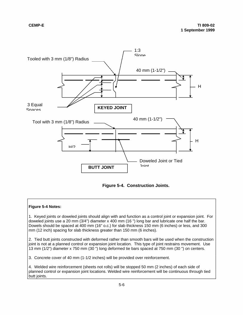
CEMP-E TI 809-021 September 1999
5-6
Figure 5-4. Construction Joints.
Figure 5-4 Notes:
1. Keyed joints or doweled joints should align with and function as a control joint or expansion joint. Fordoweled joints use a 20 mm (3/4") diameter x 400 mm (16 ") long bar and lubricate one half the bar.Dowels should be spaced at 400 mm (16" o.c.) for slab thickness 150 mm (6 inches) or less, and 300mm (12 inch) spacing for slab thickness greater than 150 mm (6 inches).
2. Tied butt joints constructed with deformed rather than smooth bars will be used when the constructionjoint is not at a planned control or expansion joint location. This type of joint restrains movement. Use13 mm (1/2") diameter x 750 mm (30 ") long deformed tie bars spaced at 750 mm (30 ") on centers.
3. Concrete cover of 40 mm (1-1/2 inches) will be provided over reinforcement.
4. Welded wire reinforcement (sheets not rolls) will be stopped 50 mm (2 inches) of each side ofplanned control or expansion joint locations. Welded wire reinforcement will be continuous through tiedbutt joints.
Tooled with 3 mm (1/8") Radius
1:3Slope
40 mm (1-1/2")
H
3 EqualSpaces KEYED JOINT
Tool with 3 mm (1/8") Radius
Doweled Joint or TiedJoint
40 mm (1-1/2")
HH/2
BUTT JOINT

CEMP-E TI 809-021 September 1999
5-7
d. Slab-On-Grade Reinforcement.
Slab-on-grade shrinkage reinforcement will be located 40 mm (1-1/2 inches) from the top ofthe slab in order to restrain shrinkage and reduce curling. Maximum spacing of reinforcingbars should not exceed three times the slab thickness. For plain wire reinforcement thespacing should not be more than 350 mm (14 inches) longitudinally and 350 mm (14 inches)transversely. The percentage of steel determined should not be less than 0.15 percent. Wiremesh reinforcements meeting the 0.15 percent steel requirement, for various slab thickness, isprovided in Table 5-1. Deformed welded wire fabric in flat sheets, or deformed reinforcing barswill be used. The positioning of the steel in the slab is critical for proper crack control.Reinforcing steel will be supported on chairs and every precaution taken to assure thereinforcing bars are positioned, as intended after construction is complete.
Table 5-1. Minimum Slab-On-Grade Reinforcement Requirements.
Slab Thickness Wire Mesh Reinforcement
100 mm (4-inch) 305 x 305 - MW 48.4 x MW 48.4 (12 x 12 - W 7.4 x W 7.5)
125 mm (5-inch) 305 x 305 - MW58.1 x MW 58.1 (12 x 12 - W9 x W 9)
150 mm (6-inch) 305 x 305 - MW 71.0 x MW 71.0 (12 x 12 - W11 x W 11)
Suppliers because of the large bar sizes and wide spacing may not normally stock the wiremesh reinforcement sizes indicated in Table 5-1. The large bar sizes are desirable to preventbending of the steel and provide adequate stiffness to keep the steel in the upper half of theslab during concrete placement. For smaller jobs [less than 7000 square meters (75,000square feet)] in those cases when the wire mesh sizes listed in Table 5-1 are unavailable, wiremesh spacing with reduced bar diameters and closer spacing may be used provided minimumsteel requirements are met.
e. Vapor Barriers. High levels of moisture in the subgrade increase slab curling. If thesubgrade can become moist because of ground water an impermeable vapor barrier should beprovided. The minimum thickness of the vapor barrier should be 1.3 mm (50 mil) and becovered with a 150 mm (6 inches) of crushed stone topped with a 13 mm (1/2 inch) thick layerof sand. The advantage of the 165mm (6-1/2 inch) stone / sand cover over the vapor barrier isthat the vapor barrier will not be punctures nor will the fill material be easily displaced asconstruction equipment is driven over the stone and sand cover (Ytterberg, 1987). If the onlypurpose of the vapor barrier is to reduce friction between the slab and subgrade in order toreduce drag, then a polyethylene slip sheet can be placed directly under the slab providedholes are punched in the polyethylene to allow water to leave the bottom of the slab beforefinal set occurs in the concrete.

CEMP-E TI 809-021 September 1999
5-8
5-4. SHINKAGE COMPENSATING CONCRETE. Edge curling and shrinkage cracking can bereduced through the use of shrinking compensating concrete that is properly reinforced. TheACI Committee 223 Report, "Standard Practice for the Use of Shrinkage-CompensatingConcrete" recommends that the area of steel reinforcement be greater than or equal to 0.15percent of the cross-sectional area of the concrete and less than or equal to 0.20 percent, andthat it be located in the upper half of the slab.
5-5. POST-TENSIONED SLABS. Post-tensioning of slabs-on-grade can be useful where it isdesirable to eliminate joints, design the slab-on-grade to resist foundation movements at sitescontaining expansive soils, or to provide the slab-on-grade system with the capacity to spanover weak subgrade areas. The Post-Tensioning Institute (PTI) Reports, "Design andConstruction of Slabs-on-Ground," and "Post-Tensioned Commercial and Industrial Floors" canbe used as a basis for design of post-tensioned slabs.
5-6. SPECIAL TESTS AND SPECIAL INSPECTIONS. In addition to the usual concretetesting, shrinkage testing of concrete mixtures to minimize shrinkage potential, modulus ofrupture testing of concrete mixtures to maximize the ability of the concrete to resist tensilestress form shrinkage and load induced flexure, should be considered.

CEMP-E TI 809-021 September 1999
6-1
CHAPTER 6
MASONRY
6-1. INTRODUCTION. Design guidance for reinforced masonry structures is provided. Plain(unreinforced) masonry design and design using "empirical" methods are generally notpermitted.
6-2. BASIS FOR DESIGN. Reinforced masonry will be designed by allowable stress design(ASD) methods in accordance with TI 809-06, "Masonry Structural Design for Buildings. Loadswill be in accordance with Chapter 1, Paragraph 7. Load combinations will be in accordancewith Chapter 1, Paragraph 8. Special design and detailing requirements for masonrystructures subjected to earthquake ground motions are provided in FEMA 302, "NEHRPRecommended Provisions for Seismic Regulations for New Buildings and in TI 809-04,"Seismic Design for Buildings". For buildings in Seismic Design Categories D, E, and F, shearkeys at the base of masonry walls may be necessary. Designers must be aware of, andcomply with all seismic design and detailing requirements.
6-3. SERVICEABILITY. Detailing of masonry structures to prevent efflorescence, and toprevent cracking due to shrinkage and temperature movements, should be in accordance withrecommendations in TI 809-06. Large expanses of roof deck with supporting systems rigidlyattached to masonry walls, pilasters, or columns can result in cracking due to thermal changesthat take place during construction. Designers should therefore include provisions in thedesign to accommodate thermal movement both during and after construction. Control jointsand expansion joints are used to control cracking due to shrinkage and thermal movement.The joints should permit movement but have sufficient strength to resist required loads. Jointsshould be weather tight when located in exterior walls. Joint location and detailingrequirements are provided in TI 809-06.
6-4. LOAD PATH INTEGRITY. Information on the design and detailing of connectionsbetween shear walls (vertical resisting elements) and floor and roof diaphragms (horizontalresisting elements) are provided in TI 809-04, TI 809-06, and FEMA 302. The design ofheaded anchor bolts and bent-bar anchors embedded in masonry, and used to connectdiaphragms and structural members to masonry, will be in accordance with FEMA 302,Paragraph 11.3.12, "Headed and Bent-Bar Anchor Bolts".
6-5. SPECIAL INSPECTIONS.
• Periodic special inspection during the preparation of mortar, the laying of masonryunits.
• Periodic inspection of vertical, horizontal, and bond beam corner reinforcement.
• Continuous special inspection during the welding of reinforcement, grouting,consolidation, reconsolidation and placement of anchors (bent bar or anchor bolts).

CEMP-E TI 809-021 September 1999
7-1
CHAPTER 7
STEEL STRUCTURE DESIGN REQUIREMENTS
7-1. INTRODUCTION. This chapter prescribes criteria for the design of structural steel, open-web joists, and cold-formed steel structural members in buildings.
7-2. GENERAL. Structural framing systems and elements of buildings will be designed inaccordance with the accepted industry standards described below. The type of steel and unitdimension, (bay size, story, height, etc.), the system for structural framing, and the designmethod used will be based on a comparative economic study and will be those that result inthe least cost for the required structure.
7-3. BASIS FOR DESIGN.
a. Structural Steel Construction. The design, fabrication and erection of structural steelfor buildings and structures will be in accordance with either the AISC Load and ResistanceFactor Design (AISC-LRFD) or AISC Specification for Structural Steel Buildings-AllowableStress Design (AISC-ASD). The seismic design of steel structures will be in accordance withthe additional provisions of TI 809-04, "Seismic Design for Buildings". Guidance on cold-formed steel can be found in TI 809-07, "Design of Load Bearing Cold-Formed Steel Systemsand Masonry Veneer / Steel Stud Walls".
b. Cold-Formed Steel. The design of cold-formed carbon and low alloy steel structureswill be in accordance with the TI 809-07. The design of cold-formed stainless steel memberswill be in accordance with ASCE 8, "Specifications for the Design of Cold-Formed StainlessSteel Structural members. Composite slabs of concrete on steel deck will be designed andconstructed in accordance with ANSI/ASCE 9, "Standard for the Structural Design ofComposite Slabs". The seismic design of cold-formed steel structures will be in accordancewith the additional provisions of TI 809-04.
c. Steel Joists. The design, manufacture, and use of open web steel joists and joistgirders will be in accordance with one of the following Steel Joist Institute (SJI) specifications:
• Standard Specifications for Open Web Steel Joists, K Series
• Standard Specifications for Longspan Steel Joists, LH Series, and Deep LongspanSteel Joists, DLH Series, or
• Standard Specifications for Joist Girders.
d. Steel Cables Structures. The design, fabrication, and erection, including relatedconnections, and protective coatings of steel cables for buildings will be in accordance withASCE 19, "Structural Applications of Steel Cables for Buildings” except as modified as followsfor seismic design:

CEMP-E TI 809-021 September 1999
7-2
• Section 5d of ASCE 19 will be modified by substituting (1.5 T4) where T4 is the nettension in the cable due to dead load, prestress, live load, and seismic load. A load factor of1.1 will be applied to the prestress force to be added to the load combination of Section 3.1.2of ASCE 19.
e. Crane Runways and Supports.
(1) Stops and Bumpers. Stops refer to rigid assemblies installed at the ends of cranerunways to prevent traveling cranes from running beyond the ends of the runway. Bumpersrefer to those devices (usually fitted onto the crane) which are resilient or other energyabsorbing construction designed to limit the deceleration force resulting from the crane's hittingthe runway stops. Stops engaging the thread of the wheel will not be less than the radius ofthe wheel. Stops engaging other parts of the crane are recommended. Requirements for thedesign of crane stops are controlled largely by the design of the crane bumpers. Procurementdocuments for cranes will mandate that crane bumpers be designed in accordance withrequirements of the Occupational Safety and Health Act (OSHA) including.
• Bumpers will be capable of stopping the crane (not including lifted load) at an averagedeceleration of no more than 3 feet per second per second with the crane traveling at 20percent of rated speed.
• Bumpers will, at a minimum, have sufficient energy absorbing capacity to stop thecrane when its traveling at 40 percent of rated speed. The forces to be resisted by thestops will either be indicated by the crane manufacturer or determined as set forth inWhiting Corporation Overhead Crane Handbook.
(2) Deflections. Vertical deflection of crane runway girders will be limited as set forth inCrane Manufacturer's Association of America (CMAA) 70 and 74. Horizontal deflection will bechecked to assure compatibility with clearance between flanges of double-flanged wheels andbearing area of single-flanged wheels.
(3) Additional Information. Additional information useful in the design of crane runwaysand supports can be found in the Navy MIL-HDBK-1038, "Weight Handling Equipment", andNavy guidance document No. P-307, "Management of Weight Handling Equipment". Thesedocuments provide information on crane loadings that can occur during operation and testing.
7-4. SERVICEABILITY.
a. General. AISC Specification for Structural Steel Buildings-Allowable Stress Design(AISC-ASD) provides design guidance with respect to the following serviceability relatedissues:
• Camber• Expansion and contraction• Deflection, vibration and drift• Connection slip

CEMP-E TI 809-021 September 1999
7-3
• Corrosion
b. Camber. Camber is especially important in truss type structures such as those typicallyused over rolling doors in aircraft hangars. In general, however, the use of camber to offsetdead load deflections in long span beams, girders, and joists has limited benefits with respectto building serviceability. Camber however can improve the appearance of structures wherethe support systems are exposed to view.
c. Expansion and Contraction. Expansion joints should be provided when necessary tominimize detrimental effects resulting from the lateral movement of long structures due tothermal expansion and contraction. In general, for non-rectangular steel-framed buildings, themaximum allowable building length without an expansion joint (or maximum length betweenexpansion joints) is 90 meters (300 feet) for moderate climates (temperature change less than0o C (30o F)). This decreases to 60 meters (200 feet) for extreme climates (temperaturechange greater than 20o C (70O F)). These distances may be increased for rectangularbuildings, however, they should be decreased if the building is unheated, if the building is airconditioned, or if the building has fixed-base columns. Additional information on expansionjoints in buildings can be found in Technical Report No. 65, “Expansion Joints in Buildings,”National Academy of Sciences, 1974. A double column arrangement is the preferred methodof establishing an expansion joint. Additional joints may be required at the junctures of T-, L-,U-shaped and other irregularly shaped buildings, or when foundation conditions create apotential for differential settlement.
d. Deflection, Vibration and Drift. Displacements of structural framing system underservice load conditions must be controlled to prevent damage to various architectural featuressuch as interior walls, partitions, ceilings, and exterior cladding. Deflection limits, expressed asa function of span length are provided in Table 1-4 and in various codes (AISC, AISI, MBMA,etc.). Drift limits for earthquake loadings are provided in FEMA 302. Designers should verifythe deflection and drift limits imposed by code are suitable. Drift limits more stringent thanthose imposed by FEMA 302 may be warranted for those conditions where non-ductilecladding is used.
e. Connection Slip. When connection slip can cause a significant displacement increasein the framing system and thereby raise concerns about building serviceability, the use of slip-critical connections should be considered. Other reasons for using slip-critical connections areprovided in Paragraph 5d.
f. Corrosion. Corrosion can reduce structural capacity as well as cause serviceabilityproblems. Painting of structural steel will comply with the requirements contained in eitherAISC-LRFD or AISC-ASD. Except where fabricated of approved corrosion resistant steel or ofsteel having a corrosion resistant or other approved coating, individual structural members andassembled panels of cold-formed steel construction must be protected against corrosion withan approved coat of paint. Requirements for the protection of steel in corrosive environmentsare provided in Chapter 12.

CEMP-E TI 809-021 September 1999
7-4
g. Requirements for Wear Protection. The total thickness of design sections subject towear will be increased beyond that required to meet stress requirements. The amount of suchincrease will be based on the material involved, the frequency of use, and the designedservice life. Estimates of the wear requirement will be based on previous experience oraccepted practice for the application. Use of replaceable wear plates should be consideredwhere extremely severe conditions exist.
7-5. LOAD PATH INTEGRITY.
a. General. Connections between framing elements are critical. They must perform atlimit state and service load levels as intended to assure load path integrity is maintained duringextreme loading events. Under service loading conditions, connection displacements androtations should not lead to serviceability problems. Connections can be welded or bolted, or acombination of both welds and bolts. Design of welded and bolted connections will be inaccordance with the either AISC Load and Resistance Factor Design (AISC-LRFD) or AISCSpecification for Structural Steel Buildings-Allowable Stress Design (AISC-ASD). Boltedconnections can be shear-bearing type connections, slip critical connections, or direct tensionconnections. Field welding of connections should be minimized to the maximum extentpossible.
b. Design of Connections for Wind and Seismic Loads. Connection design philosophy isdifferent for earthquake than it is for wind. Connections used to resist wind load are designedto perform in the elastic range. Connections used to resist earthquake loads, althoughdesigned in a fashion similar to that for wind load, are expected to experience forces greaterthan the code level design forces. This requires that earthquake resistant connections performin a ductile manner. Under certain circumstances, such as moment frame connections,bearing connections may be desirable for wind load, but slip-critical connections may berecommended to resist earthquake loads. Slip critical connections are recommended forearthquake resistant beam-column connections where web connections are bolted and flangeconnections are welded. Slippage of the bolts in these type connections can increase loadson the flange welds resulting in connection failure (Reference UCB/EERC-83/02 Report,"Seismic Moment Resisting Connections for Moment-Resisting Steel Frames": Keep in mindthat the ultimate load capacity of a slip-critical connection is the capacity of the bolts loaded inshear/bearing. If slip-critical bolts in the web connection of a moment resistant joint are toonear the yielding flanges, the bolts may experience sufficient force to slip into a shear/bearingtype of response, which may have a lower capacity than the slip-critical type of response.).There are significant differences between the strengths allowed for shear-bearing, and slipcritical bolts. Therefore, the designer must check both wind and seismic loading conditions tomake sure the connection satisfies both shear-bearing and slip-critical requirements.
c. Shear-bearing Type Connections. In a shear-bearing type connection, shear forcesare transferred through the connection by bolts that act in shear. The connected material is inbearing adjacent to the bolts and must be evaluated for its load bearing capacity. Bolt shearstrength is about 62 percent of the bolt-ultimate tensile strength. It should be recognized thatall shear and moment connections at ultimate load conditions act in shear-bearing whetherthey are designed as shear-bearing connections or as slip-critical connections. The bolts in

CEMP-E TI 809-021 September 1999
7-5
shear-bearing type connections are installed "snug tight" since shear strength in this type ofconnection is not related to the pretension load in the bolt. The bolts are usually ASTM A307bolts with an ultimate tensile strength of 450 MPa (60ksi), although "snug tight" high-strengthASTM A325 and ASTM A490 bolts are also permitted for shear-bearing type connections withsome restrictions. ASTM A325 bolts have an ultimate tensile strength of 830MPa (120 ksi),and ASTM A490 bolts have an ultimate tensile strength of 1040 MPa (150 ksi).
d. Slip Critical Connections. Slip critical connections transfer shear load by shear-frictionwith the normal force provided by pretensioning the bolts. The shear strength at service loadlevels is dependent on the pretension load (normal force on joint) and the friction betweenjoined materials. Slip-critical connections are generally required when loads are repetitive andfatigue is a concern, where connection slip would effect structure performance and where boltsand welds must act in unison to resist applied loads. Bolts are pretensioned to at least 70percent of the bolt-minimum tensile strength. The tension load is applied by tightening the nut,or otherwise elongating the bolt sufficiently to develop the prescribed pretensioning force.Turn-of-the-nut, calibrated wrench, and direct tension indicators are all methods used toassure the bolt has been properly tensioned.
e. Bolts in Direct Tension. When bolts act in tension to resist applied loads, thepossibility of, and the effect of prying action on bolt tension must be considered.
f. Steel Properties. Strength and ductility are properties important to buildingperformance. Ductility is dependent on the yield strength and chemical composition of thesteel. Buildings located in high seismic areas must be ductile if they are to survive majorearthquakes. Designers must select steels that meet needed strength and ductilityrequirements. They must recognize that ASTM A572 Grade 50 steel will meet ASTM A36requirements and most likely will be used even though ASTM A36 steel is specified.Designers specifying ASTM A36 steel must consider the impact a higher yield strength willhave on the seismic design and make sure the substitution does not adversely impact seismicperformance. Connections designed to develop the strength of the connected members maynot perform as intended if the connected members were specified to be ASTM A36 steel andthe contractor elected to substitute members of ASTM A572, Grade 50 steel.
7-6. SPECIAL INSPECTIONS.
• Periodic special inspection of the installation and tightening of fully tensioned high-strength bolts in slip critical connections and in connections subject to direct tension isrequired.
• Continuous special inspection of all structural welding, except where periodic specialinspection is allowed in FEMA 302, Chapter 3.

CEMP-E TI 809-021 September 1999
8-1
CHAPTER 8
STRUCTURAL WELDING
8-1. INTRODUCTION. A weldment may contain metals of different compositions, and thecomponents of the framing system may be rolled shapes, pipes, tubes, or plates. In general,all metals are weldable, but some are much more difficult to weld than others. Certain types ofreinforcing steels used in concrete and masonry construction can be very difficult to weld.Various types of joints are used to connect framing components, including butt joints, cornerjoints, edge joints, lap joints, and T-joints. Various types of welds are used in joining steelcomponents together, and several different welding processes can be used to make the weld.Structural engineers involved in the design of weldments must be familiar not only with thevarious types of joints and types of welding procedures, but also with the effect weldingposition has on the selection of welding procedures, and with the effect factors such as basemetal composition, electrode selection, preheat and interpass temperature, wire feed speed,travel speed, post weld treatment, ambient temperature, etc., have on weld performance.Volume change effects due to temperature gradients that occur due to welding, joint restraintconditions, and weld toughness are factors which must also be considered to assureweldments will be free from cracks that could reduce joint capacity and ductility. Corner jointsand poor weld termination can cause stress concentrations that can also lead to weldmentcracking.
8-2. BASIS FOR DESIGN. Weldments will comply with the American Welding Society (AWS)AWS D1.1, "Structural Welding Code - Steel". AWS D1.1 contains many prequalified jointdetails that are known to produce quality weldments when fabricated in accordance with AWSWelding Procedure Specifications (WPS). WPS’s are required for all welding, includingprequalified procedures. Additional guidance on welding can be found in TI 809-26, "WeldingGuidance for Buildings."
8-3. ARC WELDING PROCESSES. The most popular arc welding procedures are ShieldedMetal Arc Welding (SMAW) and Flux Core Arc Welding (FCAW). The SMAW process isdefined as "an arc welding process that produces coalescence of metals by heating them withan arc between a covered metal electrode and the work. Shielding is obtained fromdecomposition of the electrode covering. Pressure is not used and filler metal is obtained fromthe electrode." The FCAW process is defined as " an arc welding process that producescoalescence of metals by heating them with an arc between a continuous filler metal(consumable) electrode and the work. Shielding is produced by a flux contained within thetubular electrode. Additional shielding may or may not be obtained from an externally suppliedgas or gas mixture". Shielding refers to methods used to prevent the molten weld metal fromcoming in contact with gasses contained in the surrounding air. These gases, especiallyoxygen, nitrogen, and hydrogen, are the most detrimental to weld quality. Other types of arcwelding processes are carbon arc welding (CAW), gas tungsten arc welding (GTAW), plasmaarc welding (PAW), submerged arc welding (SAW), and gas metal arc welding (GMAW). Thetype of base metal usually determines which welding processes can be used.

CEMP-E TI 809-021 September 1999
8-2
8-4. WELDING POSITIONS. Welding positions include the flat position, the horizontalposition, the vertical position, and the overhead position. Certain welding processes havelimitations on which welding positions can be used. The structural engineer designing theweldment must be familiar with these restrictions, and make sure the type of weldmentspecified can actually be applied as intended considering access conditions, weld position,and any environmental conditions that could adversely influence weldment fabrication.
8-5. WELDMENTS SUBJECTED TO EARTHQUAKE AND CYCLIC LOADING CONDITIONS.Certain types of welds are not permitted to join members that may experience cyclic loadingsdue to earthquake ground motions, or due to vibratory motion caused by equipment. Partialpenetration butt joints in tension, intermittent groove welds, and intermittent fillet weld areexamples. Special Moment Resisting Frames (SMRF's) and Ordinary Moment ResistingFrames (OMRF's) used for earthquake resistance must be capable of performing in thenonlinear range (beyond yield) during major earthquakes. For SMRF's this means theweldments designed for beam column joints must have greater strength than the connectedmembers so that yielding occurs in the beam span away from the beam column joint. Weldedsteel frame design for seismic resisting moment frame systems is covered by the AmericanInstitute of Steel Construction (AISC), Seismic Provisions for Structural Steel Buildings".
8-6. WELDMENT STRENGTH AND DUCTILITY. Base metals selected for components of thestructural framing system must possess certain strength and ductility characteristics. It isimportant that the electrodes for joint weldments, as well as welding procedures, be selected toproduce a joint with strength and ductility properties equal to, or superior to, those of the basemetal.
8-7. ENVIRONMENTAL FACTORS IMPORTANT TO WELDMENT PERFORMANCE.Cracking can occur due to environmental factors such as the presence of moisture, and lowambient temperatures. Field welding should be avoided as much as possible. However, whenfield welding is required, especially under adverse environmental conditions, it is important thatAWS welding specification procedures be followed to the letter. Preheating and inter-passtemperatures are critical if cracking is to be prevented. Preheating also helps to drive ofexcess surface moisture, and retards the cooling rate thereby minimizing temperaturegradients. Controlling cool-down rates, especially during cold weather, is critical if cracking isto be eliminated.
8-8. WELDING REINFORCING STEEL. The welding of reinforcing steels is covered by AWSD 1.4, "Structural Welding Code - Reinforcing Steel.” Most reinforcing steel bars can bewelded. However, the preheat and other quality control measures that are required for barswith high carbon equivalents are extremely difficult to achieve. It is recommended that carbonequivalents be limited to 0.45 percent for No. 23 bars (No. 7 bars) and higher, and to 0.55percent for smaller bars. ASTM A615, Grade 60 reinforcing steel will most likely not meet theaforementioned carbon equivalent requirements. However, reinforcing bars meeting ASTMSpecification A706 have a low carbon equivalent, are easy to weld, and should be consideredwhen welding is required. Mechanical connectors are another way of connecting reinforcingbars. Mechanical connectors are covered in Chapter 4.

CEMP-E TI 809-021 September 1999
8-3
8-9. SPECIAL INSPECTIONS.
• Continuous special inspection for all structural welding, except periodic specialinspection is permitted for single pass fillet or resistance welds and welds loaded to lessthan 50 percent of their design strength provided the qualifications of the welder and thewelding electrodes are inspected at the beginning of the work and all welds are inspectedfor compliance with the approved construction documents at the completion of welding.
• Continuous special inspection during the welding of reinforcing steel used in concreteor masonry construction.

CEMP-E TI 809-021 September 1999
9-1
CHAPTER 9
METAL ROOFING AND METAL (STEEL) DECK DIAPHRAGMS
9-1. INTRODUCTION. This Chapter prescribes the criteria and procedures for the design ofmetal roofing and steel deck diaphragms for buildings.
9-2. METAL ROOFING. Metal roofing consists of cold-formed, corrugated, fluted or ribbedmetal sheets attached to the exterior of building structures and exposed to weather to serve asthe exterior covering of the structure. Metal roofing may be either structural, or non-structural.The structural metal roof is designed so the roofing panels support all out of plane loads.Forces in the plane of the roof due to lateral wind and earthquake forces are typically resistedby steel deck diaphragms, or in plane X-bracing. The non-structural roof depends on substrateto carry the applied loads. Metal roofing may have lapped side seams and exposed fasteners,standing side seams and hidden metal clip fasteners, or hybrid types such as those with snapseams or battens that fall somewhere in between. There are many types of metal roofingproduced by the metal manufacturing industry and care must be exercised to ensure that thetype specified is compatible with the main structural system or substrate.
9-3. METAL DECK DIAPHRAGMS.
a. Metal Deck Diaphragms without Structural Concrete Topping. Metal deck diaphragmswithout structural concrete topping are usually used for roofs of buildings where the gravityloads are light (live loads are 1000 kg / meter2 (20 psf or less). The metal deck units are oftencomposed of steel sheets ranging in thickness from 0.75 mm (0.03 inches) to 2 mm (0.08inches). The sheets are 600 mm (2 feet) to 900 mm (3 feet) wide, and formed in a repeatingpattern with ridges and valleys. Rib depths vary from 40 mm to 100 mm (1-1/2 to 4 inches) inmost cases. Decking units are attached to each other and to the structural steel supports bywelds or mechanical fasteners. Chords and collector elements in these diaphragms arecomposed of steel frame elements attached to the diaphragm. Load transfer to frameelements that act as chords or collectors is thorough shear connectors, puddle welds, screws,or shot pins.
b. Metal Deck Diaphragms with Structural Concrete Topping. Metal deck diaphragmswith structural concrete topping are frequently used on floor and roofs of buildings where theloads are moderate to heavy. The metal deck may be either a composite deck, which hasindentations, or a non-composite deck. In both cases the slab and deck act together to resistdiaphragm loads. The concrete fill may be normal weight or lightweight concrete, withreinforcing composed of wire mesh or small diameter reinforcing steel. Additional reinforcingmay be added in areas of high stress. The metal deck units are composed of gage thicknesssteel sheets, 600 mm (2 feet) to 900 mm (3 feet) wide, and are formed in a repeating patternwith ridges and valleys. Decking units are attached to structural steel supports by welds ormechanical fasteners. The concrete topping has structural properties that significantly add todiaphragm stiffness and strength. The topping should be a minimum of 65 mm (2-1/2 inches)thick. Concrete reinforcing ranges from light mesh reinforcement to a regular grid of smallreinforcing bars. Metal decking is typically composed of corrugated sheet steel from 22 gagedown to 14 gage. Rib depths vary from 40 mm to 75 mm (1-1/2 inches to 3 inches) in mostcases. Chord and collector elements in these diaphragms are considered to be composed of

CEMP-E TI 809-021 September 1999
9-2
the steel frame elements attached to the diaphragm. Load transfer to frame elements that actas chords or collector elements is usually through welds or headed studs.
c. Metal Deck Diaphragms with Nonstructural Concrete Topping. Metal deck diaphragmswith nonstructural concrete fill are typically used on roofs where gravity loads are light. Theconcrete fill, such as very lightweight insulating concrete (e.g. vermiculite), does not haveuseable structural properties. If the concrete is reinforced, reinforcing steel consists of wiremesh or small diameter reinforcing steel. To act as a diaphragm load transfer must be thesame as that provided for a metal deck diaphragm without concrete topping.
d. Horizontal Steel Bracing (Steel Truss Diaphragms). Horizontal steel bracing (steeltruss diaphragms) are often used in conjunction with structural metal roofing systems wherethe strength and stiffness of the metal roofing is incapable of carrying in-plane loads. Steeltruss diaphragm elements are typically found in conjunction with vertical framing systems thatare of structural steel framing. Steel trusses are more common in long span situations, suchas special roof structures for arenas, exposition halls, auditoriums, industrial buildings, andaircraft hangars. For steel truss elements with large in-plane loads, diagonal elements mayconsist of angles, tubes, or wide flange shapes that can act in both tension and compression.Diagonals which can act in both tension and compression are preferred, however withlightweight metal buildings the diagonals are often steel rods which can act only in tension.Sufficient load path reliability should be provided for diagonals in accordance with theredundancy recommendations of Chapter 2. Truss element connections are generallyconcentric, to provide the maximum lateral stiffness and ensure that the truss members actunder pure axial load.
9-4. BASIS FOR DESIGN.
a. Metal Roofing. The basis for the design of metal roofing is provided in TI 809-29,"Structural Considerations for Metal Roofing."
b. Metal (Steel) Deck Diaphragms. Steel deck diaphragms will be made from materialsconforming to the requirements of the American Iron and Steel Institute (AISI), Specificationsfor the Design of Cold-formed Structural Members," or ANSI/ASCE 8, "Specifications for theDesign of Cold-formed Stainless Structural Steel Members."
(1) In-plane Loads. Nominal in-plane shear strengths will be determined inaccordance with approved analytical procedures. Design strengths will be determined bymultiplying the nominal strength by a resistance factor, φ, equal to 0.60 for mechanicallyconnected diaphragms, and equal to 0.50 for welded diaphragms. Analytical procedurescontained in the Steel Deck Institute, Inc., "Diaphragm Design Manual #DDM01" are acceptedmeans for calculating in-plane shear strengths. Limits are placed on diaphragm span anddepth to span ratios to keep diaphragm in-plane displacements small enough to preventcracking of walls. The maximum span and span to depth ratio depends on diaphragm stiffnessand wall ductility. These and other additional requirements for diaphragms and theirconnections are provided in TI 809-04, "Seismic Design for Buildings."
(2) Out-of-Plane Loads. Design loads and design requirements for out-of-plane loadsfor bare metal deck roofing will be in accordance with TI 809-29, "Structural Considerations for

CEMP-E TI 809-021 September 1999
9-3
Metal Roofing." The design for out-of-plane loads for metal deck with structural concretetopping (composite steel floor deck) will be in accordance with the Steel Deck Institute, Inc.,"Design Manual for Composite Decks, Form Decks, and Roof Decks."
9-5. METAL DECK DIAPHRAGMS - STIFFNESS FOR ANALYSIS (FEMA 273). Diaphragmscan be considered to be flexible, or rigid. For flexible diaphragms, the lateral forces aredistributed from the metal deck diaphragm to the vertical lateral force resisting elements byassuming the diaphragm acts as a simple beam spanning between vertical lateral-forceresisting elements. For rigid diaphragms, the lateral forces are distributed to the verticallateral-force resisting elements based on the relative stiffnesses of the vertical lateral-forceresisting elements. Flexibility factors, provided in manufacturers’ catalogs as well as in theDiaphragm Design Manual of the Steel Deck Institute, can be used to determine whether thediaphragm should be considered as flexible or rigid. For bare metal deck diaphragms thestiffness is a function of metal thickness, rib geometry, fastener type, and fastener spacing.Procedures for calculating diaphragm flexibility are also provided in TI 809-04, "Seismic Designfor Buildings."
9-6. SPECIAL INSPECTIONS.
• Periodic special inspection is required for all welding of all steel deck and steel trusselements of the seismic force resisting system.
• Periodic special inspections are required for screw attachment, bolting, anchoring, andother fastening components within the seismic force resisting system includingdiaphragms, drag struts, collector elements, and truss elements.

CEMP-E TI 809-021 September 1999
10-1
CHAPTER 10
METAL BUILDING SYSTEMS
10-1. INTRODUCTION. A metal building system is an engineered product furnished by metalbuilding manufacturers. The metal building can be selected from a catalogue of standarddesigns or can be a custom design. Metal building systems, in general, consist of:
• rigid frames which act as the primary vertical load carrying system and as a lateralforce system in the transverse direction,
• rod or angle x-bracing for the roof truss diaphragm and for vertical lateral bracing inthe longitudinal direction,
• girts to support wall system cladding and resist wind loads,• roof purlins to support a standing seam metal roof system and roof live , loads, and• an exterior cladding system.
Many variations in framing systems are possible, and many different wall-cladding systems canbe used including metal panels, brick veneer, masonry, and precast concrete wall panels.Additional information on metal building systems can be found in TI 809-30, "Metal BuildingSystems".
10-2. METAL BUILDING OPTIMIZATION. The metal building system will be optimized, basedon ASCE 7 load and load combination requirements, to provide the lightest weight structuralsystem possible. The designer must determine if additional requirements related todisplacement, drift, durability, and redundancy should be written into the specifications toassure the final design will satisfy short and long term performance goals including function,durability, serviceability, and future expansion needs.. The major optimization occurs withrespect to the rigid frames. These frames are constructed of relatively thin plates that arewelded together. The frames use tapered webs with increased depth in the areas of highmoments. Web thickness and flange size are varied as needed. The rigid frame members aredesigned with bolted end connections for easy field assembly. Most often the flanges are weldconnected to the web on only one side to reduce fabrication costs. The secondary membersincluding girts and purlins are cold-formed with a high strength to weight ratio.
10-3. BASIS FOR DESIGN.
a. Criteria. Specifications for metal building systems usually require that design be inaccordance with the Metal Building Manufacturers Association (MBMA), "Low Rise BuildingSystems Manual,” except that design loads and load combinations will be in accordance withTI 809-01, “Load Assumptions for Buildings.” Secondary members (purlins, girts, etc.) arenormally light gage cold-formed sections for which design is governed by TI 809-07, "Design ofLoad Bearing Cold-Formed Steel Systems and Masonry Veneer / Steel Stud walls".
b. Roofing. Roofing will comply with the requirements of TI 809-29, "StructuralConsiderations for Metal Roofing."
c. Certification. American Institute of Steel Construction, Inc. (AISC) certification isrequired of all metal building system manufacturers. However, this requirement may be

CEMP-E TI 809-021 September 1999
10-2
waived for small storage type buildings with areas less than 140 square meters (1500 squarefeet).
10-4. STRENGTH AND SERVICEABILITY ISSUES.
a. General. Typically metal building systems have the minimum strength required, anduse high strength materials to keep strength to weight ratios at a maximum. This approach todesign under certain conditions can lead to serviceability problems.
b. Lateral Drift. Special attention should be paid to building drift under wind andseismic loading conditions. The maximum allowable drift will depend on the type of exteriorcladding. For rigid claddings, such as precast concrete, brick, or block masonry, the maximumdrift should be limited to h / 600. This is much lower than the h / 60 limit commonly acceptedfor buildings with flexible metal cladding.
c. Earthquake loadings. Metal building systems with heavyweight cladding must havesuitable lateral force resisting systems to resist the inertial forces generated by the claddingduring earthquake ground motions. The usual tension-only type bracing conventionally used inmetal building construction will not be adequate when heavyweight cladding is used. If rigidcladding is used, the roof diaphragm must also have sufficient stiffness to limit out-of-planewall displacements so that the cladding will not fail when the building is subjected toearthquake ground motions.
d. Mechanical Equipment Loads. The roof purlin system commonly provided withmetal building systems would not have the capacity to support hanging mechanical HVACunits or rooftop units. Where the roof is required to support such units, special framing mustbe provided.
e. Roof In-Plane Load Resistance. Metal building systems are commonly constructedwith a standing seam metal roof. Standing seam metal roof systems are incapable of resistingin-plane loads due to wind and earthquake forces. Therefore, a separate horizontal bracingsystem is required.
f. Serviceability Guidance. Metal building systems must meet the same serviceabilityrequirements specified for steel framed buildings in Chapter 7, "Steel Structure DesignRequirements". Additional guidance on serviceability can be found in the American Institute ofSteel Construction, Inc. (AISC) Steel Design Guide Series 3, "Serviceability DesignConsiderations for Low Rise Buildings".
10-5. DESIGN RESPONSIBILITY. Performance specifications are generally used to obtainmetal building systems. A professional engineer representing the owner will specify the metalbuilding system including all framing elements, roofing system, exterior cladding, interiorpartition walls, and architectural finishes. The same engineer will specify which design codes,loads, and load combinations are to be considered in the design. Unusual loads such asunbalanced snow loads, and concentrated roof loads must be clearly defined. If futureexpansion is required, this must also be conveyed so end bays can be designed withoutintermediate columns. Architectural requirements such as "R" factors for insulation shouldalso be included in the metal building specification. Metal building manufacturer's typically

CEMP-E TI 809-021 September 1999
10-3
design the building and furnish plans and specifications for building construction. The buildingmanufacturer's design must include all framing elements and their connections, and all exteriorwall and cladding systems including openings, framing around openings, and connections. Allbays where roof and wall bracing is to be installed should be identified. All interior wallsincluding connections, or separations, from the building frame system should be detailed onthe contract drawings. The foundation design will be provided with the contract documents inorder to provide a basis for bid. The foundation design will be reviewed after the buildingmanufacturer submits the final design. The final design submitted by the manufacturer shoulddescribe all loads, load combinations, and foundation reactions. With the use of gable benttype rigid frames, the foundation must be designed to resist lateral spreading forces. Thelateral force resisting anchors are usually hairpin type reinforcing bars embedded in the slab-on-grade. When spreading forces are large, direct tension ties between exterior footings maybe necessary. The foundation designer must carefully design and detail all foundation anchorsystems to make sure they can transfer loads to the foundation, and make sure they do notintercept slab-on-grade control joints or otherwise interfere with other building features. Theprofessional engineer representing the owner should track the building though the metalbuilding system design review, shop drawing review, and construction process to assure themetal building system actually supplied and erected on the site meets all design requirements.It may be required that certain features of the project, such as foundations, cladding, andconnections be redesigned during the metal building system design review phase.
10-6. SPECIAL INSPECTIONS.
• Periodic special inspections will be provided during all welding of elements of thelateral force resisting system.
• Periodic special inspections will be provided for bolting, anchoring, and otherfastening components of the lateral force resisting systems including struts, braces, andhold-downs. • Periodic special inspections will be provided during the erection and fastening ofexterior cladding to the metal building framing system.

CEMP-E TI 809-021 September 1999
11-1
CHAPTER 11
WOOD STRUCTURE DESIGN REQUIREMENTS
11-1. INTRODUCTION. This chapter provides a list of guidance documents to be used for thedesign of wood buildings. Properties of wood and other considerations influencing designincluding design of plywood elements and built-up members, wood preservation, termitecontrol, fire retardant treatment, and climatic influences are included either in this chapter or inthe referenced guidance documents in Appendix A. Guidance documents referenced includedesign standards and specifications. The use of timber construction will consider the type ofoccupancy and meet all fire protection criteria and requirements. Detailed design informationon wood buildings is not provided because wood construction is generally limited to residentialconstruction since strict fire protection standards preclude the use of wood construction formost other types of military buildings.
11-2. BASIS FOR DESIGN. The design of structural elements or systems constructedpartially or wholly of wood or wood-based products will be by allowable stress design or loadand resistance factor design. The structural analysis and construction of wood elements andstructures using allowable stress design methods will be in accordance with the applicablestandards indicated by reference in Appendix A. The structural analysis and construction ofwood elements and structures using load and resistance factor design methods will be inaccordance with AF&PA/ASCE 16, " Standard for Load and Resistance Factor Design (LRFD)for Engineered Wood Construction.” The design and construction of wood structures to resistseismic forces and the material used therein will comply with the requirements of TI 809-04,"Seismic Design for Buildings," and FEMA 302, "NEHRP Recommended Provisions forSeismic Regulations for New Buildings and Other Structures."
11-3. SERVICEABILITY CONSIDERATIONS.
a. Climatic Considerations. Engineering properties usually are not appreciably affectedwhen wood is subjected to extremely low temperatures. For cold region limitations on woodconstruction, see TM 5-852-9/AFR 88-19, Volume IX. The engineering properties of wood arenot appreciably affected in tropical climates. Rot and insect attacks, however, are aggravatedin tropical humid areas, and all timber for permanent construction in tropical areas should bepreservative treated. Bonding of wood to wood can be made by a variety of adhesives. Intropical climates, structural bonding of wood to other materials should be by means of epoxyresin adhesive.
b. Fire Retardant Treatment. Recommendations regarding the use of fire retardanttreatments are provided in the USDA Wood Handbook and the National Fire ProtectionHandbook. Pressure impregnation is the preferred treatment method.

CEMP-E TI 809-021 September 1999
11-2
c. Termite Control. Termite control measures will be used in areas prone to termiteinfestation. Soil will be treated with commonly accepted termite control products prior toconstruction.
d. Oriented Strand Board. The use of oriented strand board (OSB) for non-verticalapplications is not permitted. For floor and roof sheathing, APA structural rated plywoodsheathing only will be used. Specifically, for floors, use as a minimum, 18mm (23/32 inch)thickness APA rated STURD-I-FLOOR, 600 mm (24inches) on center span rating, Exposure 1,Tongue and Grove, glued and nailed. In addition, all of the requirements of the APA "CodePlus Floor" will be met. Ring or screw-shank nails will be used.
11-4. SPECIAL INSPECTIONS.
• Continuous special inspection during all field gluing of elements of the lateral forceresisting system is required.
• Periodic special inspections for nailing, bolting, anchoring, and other fastening ofcomponents within the lateral forces resisting system including drag struts, braces, andtie-downs is required.

CEMP-E TI 809-021 September 1999
12-1
CHAPTER 12
BUILDINGS SUBJECT TO SEVERE ENVIRIONMENTS AND EXPLOSIVE EFFECTS
12-1. INTRODUCTION. In some cases, buildings may be constructed in severe corrosiveenvironments, constructed in environments with extreme temperatures, or constructed suchthat protection of the environment due to toxic chemicals, wastewater, or explosives must beprovided. This chapter provides information so buildings constructed in severe environmentscan meet their intended performance objectives without deterioration, and without degradationthat could increase maintenance costs or shorten service life.
12-2. STEEL STRUCTURES IN CORROSIVE ENVIRONMEMTS.
a. General. When steel members will be exposed to heavy industrial pollution, saltspray, salt air, chemicals, or are to be embedded in corrosive soils, a corrosion engineer will beconsulted to recommend materials, protection, or both and to review design drawings to assurethe structure will be serviceable and durable. When appropriate, an increased thickness, i.e.,corrosion allowance, will be used to attain the required service life. For additional discussionand guidance in designing for corrosive conditions, see the National Association of CorrosionEngineers (NACE) Corrosion Handbook and other relevant NACE publications. Additionalinformation can also be found in the NAVFAC Maintenance and Operations Manual MO-307,“Corrosion Control” and in NAVFAC Interim Technical Guidance (ITG), “Cathodic ProtectionSystems”, dated May 1994.
b. Corrosion Protection of Steel Members. Corrosion protection is less of a problem instructures which have been designed to provide good drainage, designed to provide aircirculation, and designed to provide access for maintenance. Both oxygen and moisture mustbe present if corrosion is to occur. The most severe corrosion occurs in marine environmentswhere chloride ions are present. Paint systems and zinc coatings applied by the hot dipprocess or by spray on process are all good corrosion protection systems when metal surfacesare prepared properly and the coating systems are applied properly. In extremely corrosiveconditions, or where maintenance is difficult, the use of cathodic protection or stainless steelmay be warranted.
c. Design Considerations. Steel structures designed for corrosive environments shouldconsider the following corrosion protection measures.
(1) Box-shaped members should be designed so that all inside surfaces may bereadily inspected, cleaned, and painted, or should be closed entirely to prevent exposure tomoisture.
(2) The flanges of two (back to back)angle members, when not in contact, shouldhave a minimum separation of 3/8 inch to permit air circulation.
(3) Pockets or depressions in horizontal members should have drain holes to preventwater from ponding in low areas. Positive drainage should be provided away from exposed

CEMP-E TI 809-021 September 1999
12-2
steel. Column bases should be terminated on concrete curbs or piers above grade, and topsof curbs or piers will be pitched to drain.
(4) Where extremely corrosive conditions exist, consideration should be given toproviding cathodic protection in addition to protective coatings for steel members exposed tosalt water moisture environments.
(5) Structural members embedded in concrete and exterior railing, handrails, fences,guardrails, and anchor bolts will be galvanized or constructed of stainless steel.
(6) Dissimilar metals, (e.g., aluminum and steel, stainless steel and carbon steel, zinccoated steel and uncoated steel) should be isolated by appropriate means to avoid thecreation of galvanic cells which can occur when dissimilar metals come in contact.
12-3. STEEL STRUCTURES EXPOSED TO EXTREME CLIMATIC CONDITIONS.
a. Arctic and Antarctic Zones. For carbon steel, the transition from ductile to brittlebehavior occurs within temperatures to be expected in Arctic and Antarctic zones. Ductility isimportant for structures in high seismic areas. Toughness, a characteristic also affected bycold temperatures, is important for structures which could be subjected to cyclic or impactloadings. Information in ASTM A 709, "Structural Steel for Bridges", although related to bridgestructures, does contain information on fatigue and toughness useful in the design ofbuildings. Structures in cold climates, which could be subjected to cyclic or impact loads,should considered the following measures to mitigate potential fatigue and fracture problems.
(1) Provide ample fillets to avoid stress risers.
(2) Use bolted joints whenever possible. If welded joints are used, take precautionsto eliminate gas and impurities in welds. Proper preheating and post cooling are essential.
(3) Use low-carbon steels and nickel-alloy steel that have good toughnesscharacteristics at low temperatures.
b. Tropical Zones. The effect high ambient temperatures have on steel properties, withrespect to buildings constructed in tropic zones, is minimal.
12-4. STEEL STRUCTURES SUBJECTED TO ELEVATED TEMPERATURES.
a. Hot-rolled Carbon Steel. Up to 65 degrees C (150 degrees F), strength of steel willbe assumed to be same as the strength at normal temperature. Above 65 degrees C (150degrees F), the yield strength decreases with increasing temperature.
b. High-strength and Heat-treated Steels. The effect of elevated temperatures on highstrength and heat-treated steels should be thoroughly investigated. For example, quenchedand tempered materials will undergo radical changes in their mechanical properties as well astoughness when subjected to temperatures above 260 degrees C (500 degrees F).
CEMP-E TI 809-021 September 1999
12-3
12-5. CONCRETE STRUCTURES IN CORROSIVE ENVIRONMENTS.
a. General. Corrosion of reinforcing steel and other steel in concrete causes not onlydamage to the reinforcing steel, but also damage to the concrete. Rust that forms during thecorrosion process has a volume several times that of the parent material. This generatesexpansive forces that causes spalling and delamination of the concrete. Chloride ions, mostoften attributed to a salt water, or salt spray, are the major cause of reinforcing steel corrosion.As with structural steel the contact between dissimilar metals, and also between exposed steeland embedded reinforcing steel, can lead to corrosion that can damage both the steel andconcrete. The high alkaline environment of concrete protects reinforcing steel, prestressingsteel, and other embedded steel from corrosion provided the concrete is durable, has lowpermeability, and provided there is adequate concrete cover. Additional information of thecorrosion of concrete reinforcing steel can be found in ACI Committee 222 Report, "Corrosionof Metals in Concrete".
b. Concrete Cover. Concrete in a marine environment and subject to salt-water waveaction and spray should have concrete cover protection greater than that specified in ACI 318.For concrete walls that at 500 mm (20 inches) or greater in thickness the minimum concretecover will be 65 mm (2.5 inches). If possible the cover should also be 65 mm (2.5 inches) inconcrete walls that are less than 500 mm (20 inches). For concrete that is not placed withinforms, or for concrete in contact with earth, the cover requirements will be increased 15 mm(1/2 inches). However in thin members where clearances are restricted the cover can belimited to the maximum of either:
(1) 1.5 times the maximum size of aggregate, or
(2) 1.5 times the maximum diameter of reinforcement, or
(3) 20 mm (3/4 inch) cover to all steel including stirrups.
Additional information on reinforcing steel and prestressing steel detailing for structures inmarine environments, and for the design of reinforced concrete structures in marineenvironments, can be found in ACI Committee 357 Report, "Guide for the Design andConstruction of Fixed Offshore Concrete Structures".
12-6. CONCRETE STRUCTURES PROTECTING THE ENVIRONMENT.
a. General. Concrete building features that must be designed to protect theenvironment from chemical spills, or to protect water supplies from contamination, will bedesigned in accordance with the provisions of the ACI Committee 350 Report, "EnvironmentalEngineering Concrete Structures". These features include tanks, reservoirs, sewers, wet wells,pump stations, and other similar structures and appurtenances. The main purpose of ACICommittee 350 Report is to minimize cracking to avoid leakage of chemicals and wastewater.
b. Design Approach. In accordance with the ACI Committee 350 Report the designstrength required by the ACI 318 load factor equations is to be multiplied by a durabilitycoefficient equal to 1.3 to obtain the required design strength for environmentally engineeredconcrete structures. The purpose of the durability coefficient is to reduce reinforcing steel
CEMP-E TI 809-021 September 1999
12-4
stresses (and cracking potential) at service load conditions. Small diameter bars at closespacing are encouraged in order to limit crack widths. Cover requirements greater than thoseof ACI 318 are required to provide increased protection against reinforcing steel corrosion.Information on joints, joint details, and waterstops are also covered in the ACI Committee 350Report.
12-7. CONCRETE BLAST RESISTANT STRUCTURES. Design of structures to resist theeffects of accidental explosions will be in accordance with TM 5-1300/AFM 88-22/P-397,"Structures to Resist the Effects of Accidental Explosions" and Navy Design Manual (DM) 2.08,”Blast Resistant Structures.” The design of blast-resistant structures must consider thetransient loadings and dynamic response of the structure that result from the specified designevent. Blast-resistant design is often required in conjunction with the construction of weaponssystem facilities, both developmental and operational, as well as for hardened structuresdesigned to resist the effects of intentional attack.

CEMP-E TI 809-021 September 1999
13-1
CHAPTER 13
SPECIAL CONSTRUCTION
13-1. INTRODUCTION. This chapter covers the design requirements for aluminum structures,membrane structures, and other types of structures constructed using unique materials andunique construction methods not covered by the previous chapters. All special constructionmust comply to the requirements of the National Fire Protection Association.
13-2. NEW MATERIALS AND METHODS. The use of special construction is permittedwhenever it appears necessary, advantageous, and economical. However, specifying new oruntried materials or methods of construction should be avoided until the merits of the methodsor materials have been established. New, unusual, or innovative materials, systems ormethods previously untried may be incorporated into designs when evidence shows that suchuse is in the best interest of the Government from the standpoint of economy, lower-life-cyclecosts, and quality of construction. Manufacturers should prove the merits of their products bycertified laboratory results, by evidence of satisfactory installation under conditions similar tothose anticipated for the proposed construction, and by demonstrating compliance withappropriate industry standards.
13-3. SPECIAL CONSTRUCTION STANDARDS. Special construction often involves designrequirements and construction methods different from those covered by current designmanuals, construction standards, and guide specifications. In cases where specialconstructions has application beyond the scope of a particular project, the agency responsiblefor design will submit a recommended change report to the agency/or agencies responsible formaintaining and updating design guidance, construction standards and guide specifications.The recommended change report will allow current design guidance, construction standards,and/or guide specifications, to be updated to cover the new special construction method. Therecommended change report should contain justification and documentation supporting thenew special construction method, including cost benefits, proposed special criteria andcontrols, performance history, and tests.
13-4. ALUMINUM STRUCTURES. Aluminum when used for structural purposes in buildingconstruction will be designed in accordance with the Aluminum Association AA-94, Part 1-A,"Specifications for Aluminum Structures - Allowable Stress Design", and Part 1-B,"Specifications for Aluminum Structures - Load and Resistance Factor Design of Buildings andSimilar Type Structures". Approval under the provisions of Paragraphs 2 and 3 is not requiredunless the aluminum structure is part of a unique structural system.
13-5. MEMBRANE STRUCTURES. Membrane structures include membrane-covered framestructures, cable supported membrane structures, and air supported structures. Membranestructures are those which utilize an enclosure membrane acting in tension as a structuralelement. Membrane structures must either be noncombustible, or flame resistant. Structureswill be designed to sustain dead loads, loads due to tension or inflation, and live loadsincluding wind, snow and seismic loads. The use of membrane structures is particularlyapplicable to temporary construction, to situations requiring minimum structure weight, or toconditions requiring large, column-free spaces. Membrane structures are also used to coverwater storage facilities, water clarifiers, water treatment plants, greenhouses, and other

CEMP-E TI 809-021 September 1999
13-2
facilities not used for human occupancy. For additional guidance on the design of fabricstructures, see Tension Structures Behavior and Analysis by Leonard and refer to literatureavailable from the major manufacturers of structural fabrics and air-supported structures. Useof fabric structures is subject to prior approval as set forth above except when they are usedas temporary enclosures.
13-6. GLASS FIBER REINFORCED CONCRETE, FIBER COMPOSITES AND REINFORCEDPLASTICS.
a. General. Although the use of glass fiber reinforced concrete (GRFC) is used in manyinstances for building cladding, the use of other fiber composites and reinforced plastics hasbeen very limited with respect to building systems and components. These materials do offerunique advantages because of their high strength-to-weight ratio, because of the ease withwhich they can be molded into various shapes, and because of the excellent resistance theyprovide against corrosion. Other properties such as creep, modulus of elasticity, coefficient ofthermal expansion, and long term resistance to weathering and other environmental effects,however, may result in overall performance that does not measure up to the standardsassociated with the commonly used materials described in the previous chapters of this report.
b. Glass Fiber Reinforced Concrete (GRFC). Glass Fiber Reinforced Concrete (GRFC)consists of cement aggregate slurry reinforced throughout with alkali resistant glass fibers. Inbuilding construction, GRFC is primarily used for architectural precast cladding. The claddinghas an appearance similar to precast concrete, except it is much lighter which can help toreduce the cost of the building structural framing. GRFC is not used as a vertical load-bearingcomponent, although it can resist wind loads, and seismic inertial forces due to its own weight.In addition to being lightweight, GRFC panels have high impact resistance and are non-combustible. Information on use, design and construction of GFRC can be found in thePrestressed Concrete Institute (PCI) Committee Report, "Recommended Practice for GlassFiber Reinforced Concrete Panels." When used, GFRC should be evaluated for its history ofperformance under the types of climatic conditions to which the building will be exposed.Climates with temperature extremes and with high rainfall and moisture conditions have insome cases have caused deterioration of GRFC thereby effecting cladding serviceability.
c. Reinforced Plastics and Fiber Composites. Construction using fiber reinforcedplastic and fiber reinforced plastic composites is relatively new with respect to structuralapplications. Glass fiber reinforced plastic (GFRP) bars can be used in concrete beams andcolumns in order to prevent damage from the corrosive effects of salts, acids, and otheraggressive elements. The ultimate strength of GFRP bars is about twice that of reinforcingsteel, however the modulus of elasticity is only about 1/4 that of steel that could possibly causeserviceability problems related to increased deflection. Glass fiber reinforced plastic (GFRP)plates and fabric can be epoxy bonded to concrete or masonry to increase strength andductility. This shows great promise as a means for increasing the structural performance ofexisting structural systems and components, especially where structural components lack thestrength and ductility to survive major earthquake ground motion demands. Information onreinforced plastics and fiber composites can be found in the ACI Journal Technical, Paper,Title No. 91-S34, "Fiber Composites for New and Existing Structures," May-June 1994.

CEMP-E TI 809-021 September 1999
A-1
APPENDIX A
REFERENCES
GOVERNMENT PUBLICATIONS
Department of the Army - Technical Instructions
ReferenceDesignation
Title
TI 809-01 Load Assumptions for Buildings
TI 809-02 Structural Design Criteria for Buildings
TI 809-03 Structural Design Criteria for Structures Other than Buildings
TI 809-04 Seismic Design for Buildings
TI 809-05 Seismic Design for the Rehabilitation of Buildings
TI 809-06 Masonry Structural Design for Buildings
TI 809-07 Design of Load Bearing Cold-Formed Steel Systems and MasonryVeneer / Steel Stud Walls
TI 809-26 Welding Guidance for Buildings
TI 809-27 Concrete Floor Slabs on Grade Subjected to Heavy Loads
TI 809-28 Design and Construction of Reinforced Ribbed Mat Slabs
TI 809-29 Structural Considerations for Metal Roofing
TI 809-30 Metal Building Systems
TI 809-51 Seismic Screening Procedures for Military Buildings
TI 809-52 Commentary on Snow Loads
TI 809-53 Commentary on Roofing systems

CEMP-E TI 809-021 September 1999
A-2
Department of the Army - Engineering Manuals
ReferenceDesignation
Title
EM 1110-1804 Geotechnical Investigations
EM 1110-1-1905 Bearing Capacity of Soils
EM 1110-1 1908 Rock Foundations
EM 1110-2-2906 Design of Pile Foundations
Department of the Army - Technical Manuals
Reference Designation Title
TM 809-1/AFM 88-3, Ch. 1 Structural Design Criteria - Loads
TM 809-3/AFM 88-3, Ch. 3 Masonry Structural Design for Buildings
TM 809-10/ P-355/AFM 88-3,Ch. 13
Seismic Design for Buildings
TM 809-10-1/ P-355.1/AFM 88-3,Ch. 13, Sec A
Seismic Design Guidelines for Essential Buildings
TM 809-10-2/ P-355.2/AFM 88-3,Ch. 13, Sec B
Seismic Design Guidelines for Upgrading ExistingBuildings
TM 5-818-1 / AFM 88-3, Chapter 7 Soils and Geology Procedures for Foundation Designof Buildings and Other Structures (Except HydraulicStructures)
TM 5-809-11 Design Criteria for Facilities in Areas Subject to Typhoonsand Hurricanes.
TM 5-852-9/ AFR 88-19, Vol. IX Arctic and Subarctic Construction: Buildings.
TM 5-1300/AFM 88-2 Structures to Resist the Effects of AccidentalExplosions.

CEMP-E TI 809-021 September 1999
A-3
Department of the Navy
ReferenceDesignation
Title
Navy Manual P-89 (To become a Tri-Service Manual)
DOD Weather Manual
Navy Manual P-307 Management of Weight Handling Equipment
Navy Manual P-397 Structures to Resist the Effects of AccidentalExplosions
Navy Design Manual DM 2.04 Structural Engineering, Concrete Structures
Navy Design Manual DM 2.08 Blast Resistant Structures
Navy Design Manual DM 7.1 Field Exploration, Testing, andInstrumentation
Navy Design Manual DM 7.02 Foundations and Earth Structures
Navy Military Handbook MIL-HDBK 1002/1 Structural Engineering – GeneralRequirements
Navy Military Handbook MIL-HDBK 1002/3 Steel Structures
Navy Military Handbook MIL-HDBK 1002/5 Timber Structures
Navy Military Handbook MIL-HDBK 1002/6 Aluminum Structures, Composite Steel,Other Structural Materials
Navy Military Handbook MIL-HDBK 1007/3 Soil Dynamics and Special Design Aspects
Navy Handbook MIL-HDBK 1038 Weight Handling Equipment
NAVFAC Maintenance and OperationsManual M-307
Corrosion Control
NAVFAC Interim Technical Guidance (ITG) Cathodic Protection Systems, May 1994
NAVFAC Interim Technical Guidance (ITG) Minimum Design Loads for Buildings andOther Structures, 31 August 1998

CEMP-E TI 809-021 September 1999
A-4
Federal Emergency Management Agency (FEMA)
ReferenceDesignation
Title
FEMA 154 Rapid Visual Screening of Buildings for Potential Seismic Hazards: A Handbook.
FEMA 178 NEHRP Handbook for the Seismic Evaluation of Existing Buildings.
FEMA 267 Interim Guidelines, Welding of Steel Moment Frame Structures
FEMA 273 NEHRP Guidelines for the Seismic Rehabilitation of Buildings
FEMA 302 NEHRP Recommended Provisions for Seismic Regulations for New Buildings andother Structures
NONGOVERNMENT PUBLICATIONS
Aluminum Association (AA)900-19th Street NW, Suite 300Washington DC 20006
ReferenceDesignation
Title
AA-94, Part 1-A Specifications for Aluminum Structures - Allowable Stress Design
AA-94, Part 1-B Specifications for Aluminum Structures - Load and Resistance Factor Designof Buildings and Similar Type Structures".

CEMP-E TI 809-021 September 1999
A-5
American Concrete Institute (ACI)PO Box 9094Farmington Hills, MI 48333-9094
ReferenceDesignation
Title
ACI Committee 201 Report Guide to Durable Concrete
ACI Committee 211 Report Guide for Selecting the Proportions for High-Strength Concretewith Portland Cement and Fly Ash
ACI Committee 222 Report Corrosion of Metals in Concrete
ACI Committee 224 Report Control of Cracking in Concrete Structures
ACI Committee 224.3 Report Joints in Concrete Construction
ACI Committee 301 Specifications for Structural Concrete
ACI Committee 315 Report Details and Detailing of Concrete Reinforcement
ACI Committee 315R Report Manual of Engineering and Placing Drawings for ReinforcedStructures.
ACI 318 Building Code Requirements for Structural Concrete andCommentary.
ACI Committee 302 Report Guide to Concrete Floor and Slab Construction.
ACI Committee 336 Report Standard Specification for the Construction of Drilled Piers
ACI Committee 350 Report Environmental Engineering Concrete Structures
ACI Committee 351 Report Foundations for Static Equipment
ACI Committee 357 Report Guide for the Design and Construction of Fixed OffshoreConcrete Structures.
ACI Committee 360 Design of Slabs on Grade
ACI Committee 363 Report State-of-the-Art Report on High Strength Concrete
ACI Committee 439 Report Mechanical Connections of Reinforcing Bars.
ACI Committee 449 Report Concrete Nuclear Structures, Appendix B, Steel Embedments
ACI Committee 543 Report Recommendations for the Design Manufacture, and Installationof Concrete Piles
ACI Journal Technical,Paper, Title No. 91-S34
Fiber Composites for New and Existing Structures,Saadatmanesh, Hamid, May-June 1994.
ACI Journal Technical,Paper, Title No. 90-S53
Bond Stress Model for Design of Adhesive Anchors, Cook, R.A.,Doerr, G.T., and Klingner, R.E., Sept-Oct 1993

CEMP-E TI 809-021 September 1999
A-6
American Forest and Paper Association (AFPA)1111 19th Street NW, Suite 700Washington DC 20036
ReferenceDesignation
Title
NDS-91 National Design Specification for Wood Construction
AF&PA/ASCE 16 Standard for Load and Resistance Factor Design (LRFD) for EngineeredWood Construction
American Institute of Steel Construction (AISC)One East Wacker Drive, Suite 3100Chicago, IL 60601-2001
Reference Designation Title
AISC Manual of Steel Construction Load and Resistance Factor Design
AISC Manual of Steel Construction Allowable Stress Design
AISC Steel Design Guide Series 3 Serviceability Considerations for Low-Rise Buildings.
AISC Seismic Seismic Provisions for Structural Steel Buildings
AISC Engineering Journal Design of Headed Anchor Bolts, 2nd Qtr. 1983

CEMP-E TI 809-021 September 1999
A-7
American Institute of Timber Construction (AITC)7012 S. Revere Parkway, Suite 140Englewood, CO 80112
ReferenceDesignation
Title
AITC Manual of Timber Construction.
AITC 104 Typical Construction Details.
AITC 110 Standard Appearance Grades for Structural Glued Laminated Timber
AITC 112 Standard for Tongue and Groove Heavy Timber Roof Decking.
AITC 113 Standard for Dimensions of Structural Glued - Laminated Timber.
AITC 117 Structural Glued-Laminated Timber.
AITC 119 Standard Specifications for Hardwood Glued Laminated Timber.
ANSI/AITC A190.1 Structural Glued Laminated Timber.
AITC 200 Inspection Manual
AITC 500 Determination of Design Values for Structural Glued Laminated Timber.
American Iron and Steel Institute (AISI)1101 - 17th Street NW, Suite 1300Washington DC 20036-4700
ReferenceDesignation
Title
AISI Design of Cold Formed Steel Structural Members

CEMP-E TI 809-021 September 1999
A-8
APA-Engineered Wood Association (APA)PO Box 11700Tacoma, WA 98411-0700
ReferenceDesignation
Title
APA Plywood Design Specification.
APA Supplement 1 - Design & Fabrication of Plywood Curved Panels.
APA Supplement 2- Design & Fabrication of Plywood - Lumber Beams.
APA Supplement 3- Design & Fabrication of Plywood - Stressed-Skin Panels
APA Supplement 4- Design & Fabrication of Plywood Sandwich Panels
APA Supplement 5- Design & Fabrication of All-Plywood Beams.
American Society of Civil Engineers (ASCE)1801 Alexander Bell DriveReston, VA 20191-4400
ReferenceDesignation
Title
ASCE 7 Minimum Design Loads for Buildings and Other Structures
ASCE 8 Specifications for the Design of Cold-Formed Stainless Steel Structural Members
ASCE 9 Standard for the Structural Design of Composite Slabs
ASCE 19 Structural Applications of Steel Cables for Buildings

CEMP-E TI 809-021 September 1999
A-9
American Society for Testing and Materials (ASTM)100 Barr Harbor DriveWest Conshohocken, PA 19248-2959
ReferenceDesignation
Title
ASTM A36 Specification for Carbon Structural Steel
ASTM A07 Carbon Steel Bolts and Studs, 60,000 psi Tensile Strength
ASTM A325 Structural Bolts, Steel, Heat treated, 120/105 Ksi Minimum Tensile Strength
ASTM A490 Structural Joints Using ASTM A325 or A490 Bolts
ASTM A572 High-Strength Low-Alloy Columbium-Vanadium Steels of Structural Quality.
ASTM A706 Low-Alloy Steel Deformed Bars for Concrete Reinforcement
ASTM A709 Structural Steel for Bridges.
ASTM D2487 Classification of Soils for Engineering Purposes.
American Welding Society (AWS)550 NW LeJeune RoadMiami, FL 33126
ReferenceDesignation
Title
AWS D1.1 Structural Welding Code - Steel
AWS D1.4 Structural Welding Code - Reinforcing Steel
Crane Manufacture's Association of America (CMAA)8720 Red Oak Boulevard, Suite 201Charlotte, NC 28217
ReferenceDesignation
Title
CMAA Specifications for Electric Overhead Cranes.
CMAA Specifications for Top Running and Under Running Single Girder OverheadTraveling Cranes

CEMP-E TI 809-021 September 1999
A-10
International Building Code (IBC)5203 Leesburg Pike, Suite 708Falls Church, VA 22401-3401
ReferenceDesignation
Title
IBC International Building Code - Final Draft, July 1998
Metal Buildings Manufacturers Association (MBMA)1300 Sumner AvenueCleveland OH 44115-9830
ReferenceDesignation
Title
MBMA Low Rise Buildings Systems Manual
National Association of Corrosion Engineers (NACE)PO Box 218340Houston TX 77218
ReferenceDesignation
Title
NACE Corrosion Handbook.
Portland Cement Association (PCA)5420 Old Orchard RoadSkokie, IL 60077-4321
ReferenceDesignation
Title
PCA Slab Thickness Design for Industrial Concrete Floors on Grade.
PCA Concrete Floors on Ground
PCA Notes on ACI 318-95, 1996
PCA Building Movements and Joints

CEMP-E TI 809-021 September 1999
A-11
Prestressed Concrete Institute (PCI)175 W. Jackson Boulevard, Suite 1859Chicago, IL 60604-9773
ReferenceDesignation
Title
PCI Journal, V.28, No. 2, March-April 1983
Seismic Design of Prestressed Concrete Piling.
PCI Journal, V.35, No. 6,Nov.-Dec. 1990
Simulated Seismic Load Tests on Prestressed Concrete Piles andPile-Pile Cap Connections
PCU Report No. 2 Connections for Precast Prestressed Concrete Buildings
PCI Design Handbook
PCI Committee Report Recommended Practice for Glass Fiber Reinforce Concrete Panels
Post-Tensioning Institute (PTI)1717 W. Northern AvenuePhoenix, AZ 85021
ReferenceDesignation
Title
PTI Design and Construction of Post-Tensioning Slabs-on-Ground.
PTI Post-Tensioned Commercial and Industrial Floors.
Steel Deck Institute, Inc. (SDI)PO Box 9506Canton, OH 44711
ReferenceDesignation
Title
SDI Design Manual for Composite Decks, Form Decks, and Roof Decks.
SDI Diaphragm Design Manual

CEMP-E TI 809-021 September 1999
A-12
Steel Joist Institute (SJI)1205 -48th Avenue North, Suite AMyrtle Beach, SC 29577
ReferenceDesignation
Title
SJI Standard Specifications Load Tables, and Weight Tables for Steel Joists and JoistGirders
SJI Open Web Joists, K Series
SJI Longspan Steel Joists, LH Series and Deep Longspan Steel Joists, DLH Series
Truss Plate Institute, Inc. (TPI)583 D'Onofrio Drive, Suite 200Madison, WI 53719ReferenceDesignation
Title
TPI 1-1-1995 Metal Plate Connected WoodTrusses
Whiting CorporationHarvey, IL
ReferenceDesignation
Title
Overhead Crane Handbook by William M.Weaver

CEMP-E TI 809-021 September 1999
B-1
APPENDIX B
BIBLIOGRAPHY
GOVERNMENT PUBLICATIONS
Department of the Army - Engineering Manuals
ReferenceDesignation
Title
EM 1110-2-2104 Strength Design for Reinforced-Concrete Hydraulic Structures
National Academy of Science – National Research Council
ReferenceDesignation
Title
Technical ReportNo. 65
Expansion Joints in Buildings
U.S. Department of Energy
ReferenceDesignation
Title
DOE-USRL-15910
Design and Evaluation Guidelines for Department of Energy FacilitiesSubjected to Natural Phenomena Hazards
NONGOVERMENT PUBLICATIONS
American Concrete Institute (ACI)PO Box 9094Farmington Hills, MI 48333-9094
ReferenceDesignation
Title
ACI Committee 117 Report Standard Tolerances for Concrete Construction and Materials
ACI Committee 355 Report State-of-the-Art Report on Anchorage to Concrete
ACI Committee 551 Report Tilt-Up Concrete Structures
ACI Committee 530 Report Building Code Requirements for Masonry Structures
ACI Concrete International Shrinkage and Curling of Slabs on Grade, , April, May, and June,1987, Ytterberg
American Institute of Steel Construction (AISC)One East Wacker Drive, Suite 3100

CEMP-E TI 809-021 September 1999
B-2
Chicago, IL 60601-2001
Reference Designation Title
AISC Modern Steel Construction High-Strength Bolts, Kulak, Geoffrey L., March 1995
AISC Modern Steel Construction A Guide to High Strength Bolting, Disque, Robert O.,March 1996.
AISC Modern Steel Construction What Every Engineer Should Know About Welding, Miller,Duane, E., May 1997
AISC Modern Steel Construction Welding Solutions: Put Things in Perspective with theAWS D1.1 Code, Post, Jeffery, W. , March 1998
Earthquake Engineering Research Center (EERC)University of California1301 South 46th StreetRichmond CA, 94804
ReferenceDesignation
Title
UCB/EERC-83/02 Seismic Moment Resisting Connections for Moment-Resisting Steel Frames
Miscellaneous
ReferenceDesignation
Title
Prentice Hall, Inc. Modern Welding Technology, Gary, Howard B.
The James F. Lincoln ArcWelding Foundation
Design of Welded Structures, Blodgett, Omer W
McGraw-Hill Book Company Tension Structures Behavior and Analysis, Leonard, J. W.