Embed Size (px)
Citation preview

14 Design for Nonstructural Components
Robert Bachman, S.E., John Gillengerten, S.E. and Susan Dowty, S.E.
Contents
14.1 DEVELOPMENT AND BACKGROUND OF THE REQUIREMENTS FOR NONSTRUCTURAL COMPONENTS ........................................................................................ 3
14.1.1 Approach to Nonstructural Components ............................................................................... 3
14.1.2 Force Equations ..................................................................................................................... 4
14.1.3 Load Combinations and Acceptance Criteria ........................................................................ 5 14.1.4 Component Amplification Factor .......................................................................................... 6
14.1.5 Seismic Coefficient at Grade ................................................................................................. 7 14.1.6 Relative Location Factor ........................................................................................................ 7
14.1.7 Component Response Modification Factor ........................................................................... 7 14.1.8 Component Importance Factor .............................................................................................. 7
14.1.9 Accommodation of Seismic Relative Displacements ............................................................ 8 14.1.10 Component Anchorage Factors and Acceptance Criteria .................................................. 9
14.1.11 Construction Documents ................................................................................................... 9 14.2 ARCHITECTURAL CONCRETE WALL PANEL ................................................................... 10
14.2.1 Example Description ........................................................................................................... 10 14.2.2 Design Requirements ........................................................................................................... 12
14.2.3 Spandrel Panel ..................................................................................................................... 12 14.2.4 Column Cover ...................................................................................................................... 19
14.2.5 Additional Design Considerations ....................................................................................... 20
14.3 HVAC FAN UNIT SUPPORT .................................................................................................... 21 14.3.1 Example Description ........................................................................................................... 21
14.3.2 Design Requirements ........................................................................................................... 22 14.3.3 Direct Attachment to Structure ............................................................................................ 23
14.3.4 Support on Vibration Isolation Springs ............................................................................... 26

FEMA P-751, NEHRP Recommended Provisions: Design Examples
14-2
14.3.5 Additional Considerations for Support on Vibration Isolators ............................................ 31
14.4 ANALYSIS OF PIPING SYSTEMS ........................................................................................... 33 14.4.1 ASME Code Allowable Stress Approach ............................................................................ 33
14.4.2 Allowable Stress Load Combinations ................................................................................. 34 14.4.3 Application of the Standard ................................................................................................. 36
14.5 PIPING SYSTEM SEISMIC DESIGN ....................................................................................... 38 14.5.1 Example Description ........................................................................................................... 38
14.5.2 Design Requirements. .......................................................................................................... 43 14.5.3 Piping System Design .......................................................................................................... 45
14.5.4 Pipe Supports and Bracing ................................................................................................... 48 14.5.5 Design for Displacements .................................................................................................... 53
14.6 ELEVATED VESSEL SEISMIC DESIGN ................................................................................ 55 14.6.1 Example Description ........................................................................................................... 55
14.6.2 Design Requirements ........................................................................................................... 58
14.6.3 Load Combinations .............................................................................................................. 60 14.6.4 Forces in Vessel Supports .................................................................................................... 60
14.6.5 Vessel Support and Attachment ........................................................................................... 62 14.6.6 Supporting Frame ................................................................................................................ 65
14.6.7 Design Considerations for the Vertical Load-Carrying System .......................................... 69

Chapter 14: Design for Nonstructural Components
14-3
Chapter 13 of the Standard addresses architectural, mechanical and electrical components of buildings. The examples presented here illustrate many of the requirements and procedures. Design and anchorage are illustrated for exterior precast concrete cladding and for a roof-mounted HVAC unit. The rooftop unit is examined in two common installations: directly attached and isolated with snubbers. This chapter also contains an explanation of the fundamental aspects of the Standard and an explanation of how piping, designed according to the ASME Power Piping code, is checked for the force and displacement requirements of the Standard. Examples are also provided that illustrate how to treat non-ASME piping located within a healthcare facility and a platform-supported vessel located on an upper floor within a building. The variety of materials and industries involved with nonstructural components is large and numerous documents define and describe methods of design, construction, manufacture, installation, attachment, etc. Some of the documents address seismic issues, but many do not. Standard Chapter 23 contains a listing of approved standards for various nonstructural components. In addition to the Standard, the following are referenced in this chapter:
§ ACI 318 American Concrete Institute. 2008. Building Code Requirements for Structural Concrete.
§ ASHRAE APP IP American Society of Heating, Refrigeration and Air-Conditioning
Engineers (ASHRAE). 1999. Seismic and Wind Restraint Design, Chapter 53.
§ ASME B31.1 American Society of Mechanical Engineers. 2001. Power Piping Code.
§ IBC International Code Council. 2006. International Building Code.
The symbols used in this chapter are drawn from Chapter 11 of the Standard or reflect common engineering usage. The examples are presented in U.S. customary units.
14.1 DEVELOPMENT AND BACKGROUND OF THE REQUIREMENTS FOR NONSTRUCTURAL COMPONENTS
14.1.1 Approach to Nonstructural Components
The Standard requires that nonstructural components be checked for two fundamentally different demands placed upon them by the response of the structure to earthquake ground motion: resistance to inertial forces and accommodation of imposed displacements. Building codes have long had requirements for resistance to inertial forces. Most such requirements apply to the component mass and acceleration that vary with the basic ground motion parameter and a few broad categories of components. These broad categories are intended to distinguish between components whose dynamic response couples with that of the supporting structure in such a fashion as to cause the component response accelerations to be amplified above the accelerations of the structure and those components that are rigid enough with respect to the structure so that the component response is not amplified over the structural response. In recent years, a coefficient based on the function of the building or of the component has been introduced as another multiplier for components important to life safety or essential facilities. The Standard includes an equation to compute the inertial force that involves two additional concepts: variation of acceleration with relative height within the structure and reduction in design force based upon

FEMA P-751, NEHRP Recommended Provisions: Design Examples
14-4
available ductility in the component or its attachment. The Standard also includes a quantitative measure for the deformation imposed upon nonstructural components. The inertial force demands tend to control the seismic design for isolated or heavy components, whereas the imposed deformations are important for the seismic design for elements that are continuous through multiple levels of a structure or across expansion joints between adjacent structures, such as cladding or piping. The remaining portions of this section describe the sequence of steps and decisions prescribed by the Standard to check these two seismic demands on nonstructural components.
14.1.2 Force Equations The following seismic force equations are prescribed for nonstructural components (Standard Eq. 13.3-1 through 13.3-3):
0.41 2p DS p
pp
p
a S W zF R hI
⎛ ⎞= +⎜ ⎟
⎝ ⎠
1.6maxp DS p pF S I W=
0.3minp DS p pF S I W=
where: Fp = horizontal equivalent static seismic design force centered at the component’s center of gravity
and distributed relative to the component’s mass distribution ap = component amplification factor (between 1.0 and 2.5) as tabulated in Standard Table 13.5-1 for
architectural components and Standard Table 13.6-1 for mechanical and electrical components SDS = five percent damped spectral response acceleration parameter at short period as defined in
Standard Section 11.4.4 Wp = component operating weight Rp = component response modification factor (between 1.0 to 12.0) as tabulated in Standard
Table 15.5-1 for architectural components and Standard Table 13.6-1 for mechanical and electrical components
Ip = component importance factor (either 1.0 or 1.5) as indicated in Standard Section 13.1.3 z = elevation in structure of component point of attachment relative to the base h = roof elevation of the structure or elevation of highest point of the seismic force-resisting system
of the structure relative to the base The seismic design force, Fp, is to be applied independently in the longitudinal and transverse directions. Fp should be applied in both the positive and negative directions if higher demands will result. The

Chapter 14: Design for Nonstructural Components
14-5
effects of these loads on the component are combined with the effects of static loads. Standard Equations 13.3-2 and 13.3-3 provide maximum and minimum limits for the seismic design force. For each point of attachment, a force, Fp, should be determined based on Standard Equation 13.3-1. The minima and maxima determined from Standard Equations 13.3-2 and 13.3-3 must be considered in determining each Fp. The weight, Wp, used to determine each Fp should be based on the tributary weight of the component associated with the point of attachment. For designing the component, the attachment force, Fp, should be distributed relative to the component’s mass distribution over the area used to establish the tributary weight. With the exception of structural walls, which are covered by Standard Section 12.11.1 and anchorage of concrete or masonry structural walls, which is covered by Standard Section 12.11.2, each anchorage force should be based on simple statics determined by using all the distributed loads applied to the complete component. Cantilever parapets that are part of a continuous element should be checked separately for parapet forces.
14.1.3 Load Combinations and Acceptance Criteria
Load combinations for use in determining the overall demand on an item are defined in Standard Section 2.3. Earthquakes cause loads on structures and nonstructural components in both the horizontal and vertical directions. Where these loads are applied to structural and nonstructural systems, the results (forces, stresses, displacements, etc.) are called “effects”. In Standard Section 12.4.2, seismic load effects are defined. The effects resulting from horizontally applied loads are termed horizontal load effects, Eh and the effects resulting from vertically applied loads are termed vertical load effects, Ev. The Ev term is simply a constant 0.2SDS multiplied by the dead load. Because the load combinations defined in Standard Section 2.3 provide a single term, E, to define the earthquake, the horizontal and vertical load effects were sometimes misapplied by casual users of the Standard and the effects Eh and Ev were simply added as if they were applied in the same direction. To eliminate this confusion, when the Standard was reorganized as part of the development of its 2005 edition, a new Section 12.4 was added to separate the horizontal and vertical components of the seismic load and provide a reconstituted version of the load combinations provided in Section 2.3 of the Standard. The seismic load combinations substituted the vertical coefficient term, 0.2SDS (representing Ev) directly into the load combinations. These are not alternate versions of Section 2.3 but instead present expanded versions of the load combinations of Section 2.3. It was intended by the ASCE 7 Seismic Task Committee that unless otherwise noted or excepted, the load combinations provided in Section 12.4 of the Standard be used for the design of all structures and nonstructural components. The 2006 IBC has its own set of load combinations that are very similar to those provided in ASCE 7-05. In general, 2006 IBC load combinations take precedence over those of ASCE 7-05 where they are in conflict. However, for the remainder of the discussion and examples provided herein, the load combinations of Standard Section 12.4 are used. 14.1.3.1 Seismic load effects. From Section 12.4.2, the horizontal seismic load effect Eh and vertical seismic load effect Ev are determined by applying the horizontal component load Fp and the vertical dead load D, respectively, in the structural analysis as indicated below. Eh = ρQE (Standard Eq. 12.4-3) Ev = 0.2SDSD (Standard Eq. 12.4-4) where:

FEMA P-751, NEHRP Recommended Provisions: Design Examples
14-6
QE = effect of horizontal seismic forces (due to application (Standard Sec. 12.4.2-1) of Fp for nonstructural components) ρ = redundancy factor = 1.0 for nonstructural components (Standard Sec 13.3.1) D = dead load effect (due to vertical load application) Where the effects of vertical gravity loads and horizontal earthquake loads are additive, E = ρQE + 0.2SDSD And where the effects of vertical gravity load counteract those of horizontal earthquake loads, E = ρQE - 0.2SDSD where: E = effect of horizontal and vertical earthquake-induced forces 14.1.3.2 Strength load combinations. The Standard provides load combinations that are to be used to determine design member forces, stresses and displacements in Standard Sections 2.3 and 2.4. In Standard Section 2.3, load combinations are provided for Strength Design and in Standard Section 2.4, load combinations are provided for Allowable Stress Design. For purposes of the Chapter 13 examples, only the Strength Load Combinations are used. For Strength Load Combinations involving seismic loads, the terms defined above in Section 14.1.3.1 are substituted for E in the Basic Load Combinations for Strength Design of Standard Section 2.3.2 to determine the design member and connection forces to be used in conjunction with seismic loads. Once the substitutions have been made, the strength load combinations of Section 2.3.2 are presented in Standard Section 12.4.2.3, as follows: (1.2 + 0.2SDS) D + ρQE + L + 0.2S (Standard Basic Load Combination 5) (0.9 - 0.2SDS) D + ρQE + 1.6H (Standard Basic Load Combination 7) For nonstructural components, the terms L, S and H typically are zero and load combinations with overstrength generally are not applicable.
14.1.4 Component Amplification Factor
The component amplification factor, ap, found in Standard Equation 13.3-1 represents the dynamic amplification of the component relative to the maximum acceleration of the component support point(s). Typically, this amplification is a function of the fundamental period of the component, Tp and the fundamental period of the support structure, T. When components are designed or selected, the effective fundamental period of the structure, T, is not always available. Also, for most nonstructural components, the component fundamental period, Tp, can be obtained accurately only by expensive shake-table or pullback tests. As a result, the determination of a component’s fundamental period by dynamic analysis, considering T/Tp ratios, is not always practicable. For this reason, acceptable values of ap are provided in the Standard tables. Therefore, component amplification factors from either these tables or a dynamic

Chapter 14: Design for Nonstructural Components
14-7
analysis may be used. Values for ap are tabulated for each component based on the expectation that the component will behave in either a rigid or a flexible manner. For simplicity, a step function increase based on input motion amplifications is provided to help distinguish between rigid and flexible behavior. If the fundamental period of the component is less than 0.06 second, no dynamic amplification is expected and ap may be taken to equal 1.0. If the fundamental period of the component is greater than 0.06 second, dynamic amplification is expected and ap is taken to equal 2.5. In addition, a rational analysis determination of ap is permitted if reasonable values of both T and Tp are available. Acceptable procedures for determining ap are provided in Commentary Chapter 13.
14.1.5 Seismic Coefficient at Grade
The short-period design spectral acceleration, SDS, considers the site seismicity and local soil conditions. The site seismicity is obtained from the design value maps (or software) and SDS is determined in accordance with Standard Section 11.4.4. The coefficient SDS is the used to design the structure. The Standard approximates the effective peak ground acceleration as 0.4SDS, which is why 0.4 appears in Standard Equation 13.3-1.
14.1.6 Relative Location Factor
The relative location factor, 1 2 zh
⎛ ⎞+⎜ ⎟
⎝ ⎠, scales the seismic coefficient at grade, resulting in values varying
linearly from 1.0 at grade to 3.0 at roof level. This factor approximates the dynamic amplification of ground acceleration by the supporting structure.
14.1.7 Component Response Modification Factor
The component response modification factor, Rp, represents the energy absorption capability of the component’s construction and attachments. In the absence of applicable research, these factors are based on judgment with respect to the following benchmark values:
§ Rp = 1.0 or 1.5: brittle or buckling failure mode is expected
§ Rp = 2.5: some minimal level of energy dissipation capacity
§ Rp = 3.5: ductile materials and detailing
§ Rp = 4.5: non-ASME B31 conforming piping and tubing with threaded joints and/or mechanical couplings
§ Rp = 6.0: ASME 31 conforming piping and tubing with thread joints and/mechanical couplings
§ Rp = 9.0 or 12.0: highly ductile piping and tubing joined with brazing or butt welding
14.1.8 Component Importance Factor
The component importance factor, Ip, represents the greater of the life safety importance and the hazard exposure importance of the component. The factor indirectly accounts for the functionality of the component or structure by requiring design for a lesser amount of inelastic behavior (or higher force

FEMA P-751, NEHRP Recommended Provisions: Design Examples
14-8
level). It is assumed that a lesser amount of inelastic behavior will result in a component that will have a higher likelihood of functioning after a major earthquake.
14.1.9 Accommodation of Seismic Relative Displacements
The Standard requires that seismic relative displacements, Dp, be determined in accordance with several equations. For two connection points on Structure A (or on the same structural system), one at Level x and the other at Level y, Dp is determined from Standard Equation 13.3-5 as follows: p xA yAD δ δ= − Because the computed displacements frequently are not available to the designer of nonstructural components, one may use the maximum permissible structural displacements per Standard Equation 13.3-6:
( )– x y
p aAsx
h hD
h= Δ
For two connection points on Structures A and B (or on two separate structural systems), one at Level x and the other at Level y, DP is determined from Standard Equations 13.3-7 and 13.3-8 as follows: p xA yBD δ δ= +
y aBx aAp
sx sx
hhDh h
ΔΔ= +
where: Dp = seismic relative displacement that the component must be designed to accommodate. δxA = deflection of building Level x of Structure A, determined by an elastic analysis as defined in
Standard Section 12.8.6 including being multiplied by the Cd factor. δyA = deflection of building Level y of Structure A, determined in the same fashion as δxA. hx = height of upper support attachment at Level x as measured from the base. hy = height of lower support attachment at Level y as measured from the base. ΔaA = allowable story drift for Structure A as defined in Standard Table 12.2-1. hsx = story height used in the definition of the allowable drift, Δa, in Standard Table 12.2-1. δyB = deflection of building Level y of Structure B, determined in the same fashion as δxA. ΔaB = allowable story drift for Structure B as defined in Standard Table 12.2-1. Note that ΔaA/hsx =
the drift index.

Chapter 14: Design for Nonstructural Components
14-9
The effects of seismic relative displacements must be considered in combination with displacements caused by other loads as appropriate. Specific methods for evaluating seismic relative displacement effects of components and associated acceptance criteria are not specified in the Standard. However, the intention is to satisfy the purpose of the Standard. Therefore, for nonessential facilities, nonstructural components can experience serious damage during the design-level earthquake provided they do not constitute a serious life-safety hazard. For essential facilities, nonstructural components can experience some damage or inelastic deformation during the design-level earthquake provided they do not significantly impair the function of the facility.
14.1.10 Component Anchorage Factors and Acceptance Criteria
Design seismic forces in the connected parts, Fp, are prescribed in Standard Section 13.4. Anchors embedded in concrete or masonry are proportioned to carry the least of the following:
§ 1.3 times the prescribed seismic design force, or
§ The maximum force that can be transferred to the anchor by the component or its support. The value of Rp used in Section 13.3.1 to determine the forces in the connected part (i.e., the anchor) shall not exceed 1.5 unless at least one of the following conditions is satisfied:
§ The component anchorage is designed to be governed by the strength of a ductile steel element.
§ The anchorage design of post-installed anchors is tested for seismic application in accordance with the procedures of ACI 355.2 and has a design capacity determined in accordance with ACI 318 Appendix D.
§ The anchor is designed in accordance with Standard Section 14.2.2.14.
Determination of design seismic forces in anchors must consider installation eccentricities, prying effects, multiple anchor effects and the stiffness of the connected system. Use of power actuated fasteners is not permitted for seismic design tension forces in Seismic Design Categories D, E and F unless approved for such loading. It should be noted that the term used in previous editions of the Standard was “powder” actuated instead of “power” actuated. The term was changed to cover a broader range of fastener types than is implied by “powder-driven”. Per Standard Sections 14.2.2.17 and 14.2.2.18, the design strength of anchors in concrete is to be determined in accordance with ACI 318 Appendix D as modified by these Standard Sections.
14.1.11 Construction Documents
Construction documents must be prepared by a registered design professional and must include sufficient detail for use by the owner, building officials, contractors and special inspectors; Standard Section 13.2.7 includes specific requirements.

FEMA P-751, NEHRP Recommended Provisions: Design Examples
14-10
14.2 ARCHITECTURAL CONCRETE WALL PANEL
14.2.1 Example Description
In this example, the architectural components are a 4.5-inch-thick precast normal-weight concrete spandrel panel and a column cover supported by the structural steel frame of a five-story building, as shown in Figures 14.2-1 and 14.2-2.
Figure 14.2-1 Five-story building elevation showing panel location (1.0 ft = 0.3048 m)
5 at
13'
-6" =
67'
-6"
24'-0"
Structuralsteel frame
Typical windowframe system
Spandrel panelunder consideration
Column coverunder consideration

Chapter 14: Design for Nonstructural Components
14-11
Figure 14.2-2 Detailed building elevation (1.0 ft = 0.3048 m)
The columns at the third level of the five-story office building support the spandrel panel under consideration. The columns between the third and fourth levels of the building support the column cover under consideration. The building, located near a significant active fault in Los Angeles, California, is assigned to Occupancy Category II. Wind pressures normal to the building are 17 psf, determined in accordance with the Standard. The spandrel panel supports glass windows weighing 10 psf. This example develops prescribed seismic forces for the selected spandrel panel and prescribed seismic displacements for the selected column cover. It should be noted that details of precast connections vary according to the preferences and local practices of the precast panel supplier. In addition, some connections may involve patented designs. As a result, this example will concentrate on quantifying the prescribed seismic forces and displacements. After the prescribed seismic forces and displacements are determined, the connections can be detailed and designed according to the appropriate AISC and ACI codes and the recommendations of the Precast/Prestressed Concrete Institute (PCI).
13'-6
" sto
ry h
eigh
t
T.O.S
T.O.S
24'-0"6'
-6"
pane
l7'
-0"
colu
mn
cove
r3'-0"
Spandrel panelunder consideration
Typical windowframe system
Column coverunder consideration
~
~

FEMA P-751, NEHRP Recommended Provisions: Design Examples
14-12
14.2.2 Design Requirements
14.2.2.1 Provisions parameters and coefficients ap = 1.0 for wall panels (Standard Table 13.5-1) ap = 1.25 for fasteners of the connecting system (Standard Table 13.5-1) SDS = 1.487 (for the selected location and site class) (given) Seismic Design Category = D (Standard Table 11.6-1) Spandrel panel Wp = (150 lb/ft3)(24 ft)(6.5 ft)(0.375 ft) = 8,775 lb Glass Wp = (10 lb/ft2)(21 ft)(7 ft) = 1,470 lb (supported by spandrel panel) Column cover Wp = (150 lb/ft3)(3 ft)(7 ft)(0.375 ft) = 1,181 lb Rp = 2.5 for wall panels (Standard Table 13.5-1) Rp = 1.0 for fasteners of the connecting system (Standard Table 13.5-1) Ip = 1.0 (Standard Sec. 13.1.3)
40.5 ft 0.667.5 ft
zh= = (at third floor)
According to Standard Section 13.3.1 (and repeated in Section 12.3.4.1 Item 3), the redundancy factor, ρ, does not apply to the design of nonstructural components and therefore may be taken as 1.0 in load combinations where it appears. 14.2.2.2 Performance criteria. Component failure must not cause failure of an essential architectural, mechanical, or electrical component (Standard Sec. 13.2.3). Component seismic attachments must be bolted, welded, or otherwise positively fastened without considering the frictional resistance produced by the effects of gravity (Standard Sec. 13.4). The effects of seismic relative displacements must be considered in combination with displacements caused by other loads as appropriate (Standard Sec. 13.3.2). Exterior nonstructural wall panels that are attached to or enclose the structure must be designed to resist the forces in accordance with Standard Section 13.3.1 and must be able to accommodate movements of the structure resulting from response to the design basis ground motion, Dp, or temperature changes (Standard Sec. 13.5.3).
14.2.3 Spandrel Panel 14.2.3.1 Connection details. Figure 14.2-3 shows the types and locations of connections that support one spandrel panel.

Chapter 14: Design for Nonstructural Components
14-13
Figure 14.2-3 Spandrel panel connection layout from interior (1.0 ft = 0.3048 m)
The connection system must resist the weight of the panel and supported construction including the eccentricity between that load and the supports as well as inertial forces generated by response to the seismic motions in all three dimensions. Furthermore, the connection system must not create undue interaction between the structural frame and the panel, such as restraint of the natural shrinkage of the panel or the transfer of floor live load from the beam to the panel. The panels are usually very stiff compared to the frame and this requires careful release of potential constraints at connections. PCI’s Architectural Precast Concrete (Third Edition, 1989) provides an extended discussion of important design concepts for such panels. For this example, the basic gravity load and vertical accelerations are resisted at the two points identified as A, which provide the recommended simple and statically determinant system for the main gravity weight. The eccentricity of vertical loads is resisted by a force couple at the two pairs of A1 and A connections. Horizontal loads parallel to the panel are resisted by the A connections. Horizontal loads perpendicular to the panel are resisted by two pairs of A and A1 connections and the pair of midspan B connections. The A connections, therefore, restrain movement in three dimensions while the A1 and B connections restrain movement in only one dimension, perpendicular to the panel. Connection components can be designed to resolve some eccentricities by bending of the element; for example, the eccentricity of the horizontal in-plane force with the structural frame can be resisted by bending the A connection. The practice of resisting the horizontal in-plane force at two points varies with seismic demand and local industry practice. The option is to resist all of the in-plane horizontal force at one connection in order to avoid restraint of panel shrinkage. The choice made here depends on local experience indicating that
A
A1
A
A1
B
B
3rd Story beam
6'-6
"pa
nel
7'-0
"co
lum
n co
ver/
win
dow
fram
e
24'-0"
Panel C.G.

FEMA P-751, NEHRP Recommended Provisions: Design Examples
14-14
precast panels of this length have been restrained at the two ends without undue shrinkage restraint problems. The A and A1 connections are often designed to take the loads directly to the columns, particularly on steel moment frames where attachments to the flexural hinging regions of beams are difficult to accomplish. The lower B connection often requires an intersecting beam to provide sufficient stiffness and strength to resist the loads. The column cover is supported both vertically and horizontally by the column, transfers no loads to the spandrel panel and provides no support for the window frame. The window frame is supported both vertically and horizontally along the length of the spandrel panel and transfers no loads to the column covers. 14.2.3.2 Prescribed seismic forces. Lateral forces on the wall panels and connection fasteners include seismic loads and wind loads. Design for wind forces is not illustrated here. 14.2.3.2.1 Panels. D = Wp = 8,775 lb + 1,470 lb = 10,245 lb (vertical gravity effect)
( )( )( )
( )( )( )0.4 1.0 1.487 10,245 lb
1 2 0.62.5
1.0pF = + = 5,362 lb (Standard Eq. 13.3-1)
1.6(1.487)(1.0)(10,245 lb)
maxpF = = 24,375 lb (Standard Eq. 13.3-2) 0.3(1.487)(1.0)(10,245 lb)
minpF = = 4,570 lb (Standard Eq. 13.3-3) Eh = ρQE (Standard Eq. 12.4-3) Ev = 0.2SDSD (Standard Eq. 12.4-4) where: QE (due to horizontal application of Fp) = 5,362 lb (Standard Sec. 12.4.2-1) ρ = 1.0 (because panels are nonstructural components) (Standard Sec 13.3.1) D = dead load effect (due to vertical load application) Substituting, the following is obtained: Eh = ρQE = (1.0)(5,362 lb) = 5,362 lb (horizontal earthquake effect) Ev = 0.2SDSD = 0.2SDSD = (0.2)(1.487)(10,245 lb) = 3,047 lb (vertical earthquake effect) The above terms are then substituted into the following Basic Load Combinations for Strength Design from Section 12.4.2.3 to determine the design member and connection forces to be used in conjunction with seismic loads.

Chapter 14: Design for Nonstructural Components
14-15
(1.2 + 0.2SDS) D + ρQE + L + 0.2S (Standard Basic Load Combination 5) (0.9 - 0.2SDS) D + ρQE + 1.6H (Standard Basic Load Combination 7) For nonstructural components, the terms L, S and H typically are zero and load combinations with overstrength generally are not applicable. 14.2.3.2.2 Connection fasteners. The Standard specifies a reduced Rp and an increased ap for “fasteners” with the intention of preventing premature failure in those elements of connections that are inherently brittle, such as embedments that depend on concrete breakout strength, or are simply too small to adequately dissipate energy inelastically, such as welds or bolts. The net effect more than triples the design seismic force.
( )( )( )
( )( )( )0.4 1.25 1.487 10,245 lb
1 2 0.61.0
1.0pF = + = 16,757 lb (Standard Eq. 13.3-1)
1.6(1.487)(1.0)(10,245 lb)
maxpF = = 24,375 lb (Standard Eq. 13.3-2) 0.3(1.487)(1.0)(10,245 lb)
minpF = = 4,570 lb (Standard Eq. 13.3-3) Eh = ρQE (Standard Eq. 12.4-3) Ev = 0.2SDSD (Standard Eq. 12.4-4) where: QE (due to horizontal application of Fp) = 16,757 lb (Standard Sec. 12.4.2-1) ρ = 1.0 (because panels are nonstructural components) (Standard Sec 13.3.1) D = dead load effect (due to vertical load application) Substituting, the following is obtained: Eh = ρQE = (1.0)(16,757 lb) = 16,757 lb (horizontal earthquake effect) Ev = 0.2SDSD = 0.2SDSD = (0.2)(1.487)(10,245 lb) = 3,047 lb (vertical earthquake effect) The above terms are then substituted into the following Basic Load Combinations for Strength Design from Section 12.4.2.3 to determine the design member and connection forces to be used in conjunction with seismic loads. (1.2 + 0.2SDS) D + ρQE + L + 0.2S (Standard Basic Load Combination 5) (0.9 - 0.2SDS) D + ρQE + 1.6H (Standard Basic Load Combination 7) For precast panels, the terms L, S and H typically are zero. Load combinations with overstrength generally are not applicable to nonstructural components.

FEMA P-751, NEHRP Recommended Provisions: Design Examples
14-16
14.2.3.3 Proportioning and design. 14.2.3.3.1 Panels. The wall panels should be designed for the following loads in accordance with ACI 318. The design of the reinforced concrete panel is standard and is not illustrated in this example. Spandrel panel moments are shown in Figure 14.2-4. Reaction shears (Vu), forces (Hu) and moments (Mu) are calculated for applicable strength load combinations. For this example, the values of F, L, S and H are assumed to be zero.
Figure 14.2-4 Spandrel panel moments Standard Basic Load Combination 1: 1.4(D + F) (from Standard Sec. 2.3.2) Vu = 1.4(10,245 lb) = 14,343 lb (vertical load downward)
( )( )14,343 lb 24 ft8uxM = = 43,029 ft-lb (strong axis moment)
L = Column spacing
Vu = Dead and/or earthquake load
Hu = Wind or earthquake load
Strongaxis
Mux
Weakaxis
Muy
Vu L8
32Hu L

Chapter 14: Design for Nonstructural Components
14-17
Standard Basic Load Combination 5: (1.2 + 0.2SDS) D + ρQE + L + 0.2S Vumax = [1.2 + 0.2(1.487)] (10,245 lb) = 15,341 lb (vertical load downward) 1.0(5,362 lbs)uH⇔ = = 5,362 lb (horizontal load parallel to panel) 1.0(5,362 lbs)uH⊥ = = 5,362 lb (horizontal load perpendicular to panel)
( )( )15,341 lb 24 ft8maxuxM = = 46,023 ft-lb (strong axis moment)
( )( )5,362 lb 24 ft32uyM = = 4,022 ft-lb (weak axis moment)
Standard Basic Load Combination 7: (0.9 - 0.2SDS) D + ρQE + 1.6H Vumin = [1.2 – 0.2(1.487)] (10,245 lb) = 6,174 lb (vertical load downward) 1.0(5,362 lb)uH⇔ = = 5,362 lb (horizontal load parallel to panel) 1.0(5,362 lb)uH⊥ = = 5,362 lb (horizontal load perpendicular to panel)
( )( )6,174 lb 24 ft8minuxM = = 18,522 ft-lb (strong axis moment)
( )( )5,362 lb 24 ft32uyM = = 4,022 ft-lb (weak axis moment)
14.2.3.3.2 Connection fasteners. The connection fasteners should be designed for the following loads in accordance with ACI 318 (Appendix D) and the AISC specification. There are special reduction factors for anchorage in high seismic demand locations and those reduction factors would apply to this example. The design of the connection fasteners is not illustrated in this example. Spandrel panel connection forces are shown in Figure 14.2-5. Reaction shears (Vu), forces (Hu) and moments (Mu) are calculated for applicable strength load combinations.

FEMA P-751, NEHRP Recommended Provisions: Design Examples
14-18
Figure 14.2-5 Spandrel panel connection forces Standard Basic Load Combination 1: 1.4(D + F) (from Standard Section 2.3.2)
( )1.4 10,245 lb2uAV = = 7,172 lb (vertical load downward at Points A and A1)
MuA = (7,172 lb)(1.5 ft) = 10,758 ft-lb (moment resisted by paired Points A and A1) Horizontal couple from moment at A and A1 = 10758 / 1.33 = 8071 lb Standard Basic Load Combination 5: (1.2 + 0.2SDS) D + ρQE + L + 0.2S
( ) ( )
max
1.2 0.2 1.487 10,245 lb2uAV
⎡ ⎤+⎣ ⎦= = 7,671 lb (vertical load downward at Point A)
31.0(16,757 lb)16uAH⊥ = = 3,142 lb (horizontal load perpendicular to panel at Points A and A1)
HAin = (7,671 lb)(1.5 ft) / (1.33 ft) + (3142 lb)(2.0 ft) / (1.33 ft) = 13366 lb (inward force at Point A) HA1out = (7671 lb)(1.5 ft) / (1.33 ft) + (3,142 lb)(0.67) / (1.33 ft) = 10222 lb(outward force at Point A1)
1.0(16,757 lb)2uAH⇔ = = 8,378 lb (horizontal load parallel to panel at Point A)
Mu2A = (8,378 lb)(1.5 ft) = 12,568 ft-lb (flexural moment at Point A)
D = DeadE = EarthquakeW = WindR = Reaction
Panel C.G.
RA
RA1
RA
E, W
D
E
1'-6"
1'-4
"8"1'
-4"

Chapter 14: Design for Nonstructural Components
14-19
51.0(16,757 lb)8uBH⊥ = = 10,473 lb (horizontal load perpendicular to panel at Points B and B1)
HB = (10,743 lb)(2.0 ft) / (1.33 ft) = 15,714 lb (inward or outward force at Point B) HB1 = (10,473 lb)(0.67 ft) / (1.33 ft) = 5,237 lb (inward or outward force at Point B1) Standard Basic Load Combination 7: (0.9 - 0.2SDS) D + ρQE + 1.6H
( ) ( )
min
1.2 - 0.2 1.487 10,245 lb2uAV
⎡ ⎤⎣ ⎦= = 3,086 lb (vertical load downward at Point A)
Horizontal forces are the same as combination 1.2D + 1.0E. No uplift occurs; the net reaction at Point A is downward. Maximum forces are controlled by prior combination. It is important to realize that inward and outward acting horizontal forces generate different demands where the connections are eccentric to the center of mass, as in this example. Only the maximum reactions are computed above. 14.2.3.4 Prescribed seismic displacements. Prescribed seismic displacements are not applicable to the building panel because all connections are at essentially the same elevation.
14.2.4 Column Cover
14.2.4.1 Connection details. Figure 14.2-6 shows the key to the types of forces resisted at each column cover connection.
Figure 14.2-6 Column cover connection layout (1.0 ft = 0.3048 m)
1'-3
"6'
-0"
1'-6"
24'-0"
Cover C.G.
C E
ED
7'-0
"co
lum
n co
ver
win
dow
fram
e
6'-6
"pa
nel

FEMA P-751, NEHRP Recommended Provisions: Design Examples
14-20
Vertical loads, horizontal loads parallel to the panel and horizontal loads perpendicular to the panel are resisted at Point C. The eccentricity of vertical loads is resisted by a force couple at Points C and D. The horizontal load parallel to the panel eccentricity between the panel and the support is resisted in flexure of the connection. The connection is designed to take the loads directly to the columns. Horizontal loads parallel to the panel are all resisted at Point D. The vertical load eccentricity between the panel and the support is resisted by a force couple of Points C and D. The eccentricity of horizontal loads parallel to the panel is resisted by flexure at the connection. The connection is designed to not restrict vertical movement of the panel due to thermal effects or seismic input. The connection is designed to take the loads directly to the columns. Horizontal loads perpendicular to the panel are resisted equally at Points C and D and the two points identified as E. The connections are designed to take the loads directly to the columns. There is no load eccentricity associated with the horizontal loads perpendicular to the panel. In this example, all connections are made to the sides of the column because usually there is not enough room between the outside face of the column and the inside face of the cover to allow a feasible load-carrying connection. 14.2.4.2 Prescribed seismic forces. Calculation of prescribed seismic forces for the column cover is not shown in this example. They should be determined in the same manner as illustrated for the spandrel panels. 14.2.4.3 Prescribed seismic displacements. The results of an elastic analysis of the building structure usually are not available in time for use in the design of the precast cladding system. As a result, prescribed seismic displacements usually are calculated based on allowable story drift requirements: hsx = story height = 13’-6” hx = height of upper support attachment = 47’-9” hy = height of lower support attachment = 41’-9” ΔaA = 0.020hsx (Standard Table 12.12-1)
Dpmax = ( )– x y aA
sx
h h
h
Δ =
( )72 in. 0.020 sx
sx
hh
= 1.44 in. (Standard Eq. 13.3-6)
The joints at the top and bottom of the column cover must be designed to accommodate an in-plane relative displacement of 1.44 inches. The column cover will rotate somewhat as these displacements occur, depending on the nature of the connections to the column. If the supports at one level are “fixed” to the columns while the other level is designed to “float,” then the rotation will be that of the column at the point of attachment.
14.2.5 Additional Design Considerations 14.2.5.1 Window frame system. The window frame system is supported by the spandrel panels above and below. Assuming that the spandrel panels move rigidly in-plane with each floor level, the window frame system must accommodate a prescribed seismic displacement based on the full story height.

Chapter 14: Design for Nonstructural Components
14-21
Dpmax = ( )– x y aA
sx
h h
h
Δ =
( )162 in. 0.020 sx
sx
hh
= 3.24 in. (Standard Eq. 13.3-6)
The window frame system must be designed to accommodate an in-plane relative displacement of 3.24 inches between the supports. Normally this is accommodated by a clearance between the glass and the frame. Standard Section 13.5.9.1 prescribes a method of checking such a clearance. It requires that the clearance be large enough so that the glass panel will not fall out of the frame unless the relative seismic displacement at the top and bottom of the panel exceeds 125 percent of the predicted value amplified by the building importance factor. If hp and bp are the respective height and width of individual panes and if the horizontal and vertical clearances are designated c1 and c2, respectively, then the following expression applies:
21
12 1 1.25p
clear pp
h cD c D
b c⎛ ⎞
= + ≥⎜ ⎟⎜ ⎟⎝ ⎠
(Standard Sec. 13.5.9.1)
For hp = 7 feet, bp = 5 feet and Dp = 3.24 inches and setting c1 = c2, the required clearance is 0.84 inch. 14.2.5.2 Building corners. Some thought needs to be given to seismic behavior at external building corners. The preferred approach is to detail the corners with two separate panel pieces, mitered at a 45 degree angle, with high grade sealant between the sections. An alternative choice of detailing L-shaped corner pieces would introduce more seismic mass and load eccentricity into connections on both sides of the corner column. 14.2.5.3 Dimensional coordination. It is important to coordinate dimensions with the architect and structural engineer. Precast concrete panels must be located a sufficient distance from the building structural frame to allow room for the design of efficient load transfer connection pieces. However, distances must not be so large as to increase unnecessarily the load eccentricities between the panels and the frame.
14.3 HVAC FAN UNIT SUPPORT
14.3.1 Example Description
In this example, the mechanical component is a 4-foot-high, 5-foot-wide, 8-foot-long, 3,000-pound HVAC fan unit that is supported on the two long sides near each corner (Figure 14.3-1). The component is located at the roof level of a five-story office building, near a significant active fault in Los Angeles, California. The building is assigned to Occupancy Category II. Two methods of attaching the component to the 4,000 psi, normal-weight roof slab are considered, as follows:
§ Direct attachment to the structure with 36 ksi, carbon steel, cast-in-place anchors.
§ Support on vibration isolation springs that are attached to the slab with 36 ksi, carbon steel, post-installed expansion anchors. The nominal gap between the vibration spring seismic restraints and the base frame of the fan unit is presumed to be greater than 0.25 in.

FEMA P-751, NEHRP Recommended Provisions: Design Examples
14-22
Figure 14.3-1 HVAC fan unit (1.0 ft = 0.3048 m, 1.0 lb = 4.45 N)
14.3.2 Design Requirements
14.3.2.1 Seismic design parameters and coefficients. ap = 2.5 for both direct attachment and spring isolated (Standard Table 13.6-1) ap = 2.5 (Standard Table 13.6-1) SDS = 1.487 (for the selected location and site class) (given) Seismic Design Category = D (Standard Table 11.6-1) Wp = 3,000 lb (given) Rp = 6.0 for HVAC fans, directly attached (not vibration isolated) (Standard Table 13.6-1) Rp = 2.0 for spring isolated components with restraints (Standard Table 13.6-1)
Rp = 1.5 for anchors in concrete or masonry unless criteria of Standard Section 13.4.2 are satisfied Ip = 1.0 (Standard Sec. 13.1.3) z/h = 1.0 (for roof-mounted equipment)
Concrete Concrete
b = 5'-6"a = 7'-0"
4'-0
"
2'-0
"
Center-of-mass
Elevation
Plan
8'-0"
5'-0
"
Attachment location (typical).Direct attachment shownHVAC fan unit
W = 3,000 lbs
Elevation

Chapter 14: Design for Nonstructural Components
14-23
14.3.2.2 Performance criteria. Component failure should not cause failure of an essential architectural, mechanical, or electrical component (Standard Sec. 13.2.3). Component seismic attachments must be bolted, welded, or otherwise positively fastened without consideration of frictional resistance produced by the effects of gravity (Standard Sec. 13.4). Anchors embedded in concrete or masonry must be proportioned to carry the lesser of (a) 1.3 times the force in the component and its supports due to the prescribed forces and (b) the maximum force that can be transferred to the anchor by the component and its supports (Standard Sec. 13.4.2). Attachments and supports transferring seismic loads must be constructed of materials suitable for the application and must be designed and constructed in accordance with a nationally recognized structural standard (Standard Sec. 13.6.5). Components mounted on vibration isolation systems must have a bumper restraint or snubber in each horizontal direction. Vertical restraints must be provided where required to resist overturning. Isolator housings and restraints must also be constructed of ductile materials. A viscoelastic pad, or similar material of appropriate thickness, must be used between the bumper and equipment item to limit the impact load (Standard Table 13.6-1, footnote b). Such components also must resist doubled seismic design forces if the nominal clearance (air gap) between the equipment support frame and restraints is greater than 0.25 in. (Standard Table 13.6-1, footnote b).
14.3.3 Direct Attachment to Structure
This section illustrates design for cast-in-place concrete anchors that satisfies the requirements of ACI 318, Appendix D, where the component anchorage embedment strength is greater than the strength capacity of the ductile steel anchorage element. Therefore, the Rp of the component (Rp = 6) can be used for the component anchorage design. 14.3.3.1 Prescribed seismic forces. See Figure 14.3-2 for a free-body diagram for seismic force analysis.
Figure 14.3-2 Free-body diagram for seismic force analysis (1.0 ft = 0.348 m)
Fp = ( )0.4(2.5)(1.487)(3,000 lb) 1 2 1(6.0 /1.0)
⎡ ⎤+⎣ ⎦ = 2,231 lb (Standard Eq. 13.3-1)
Ru
Vu Vu
Tu
D
ρQ E
0.2SDS D
2'-0"
5'-6"

FEMA P-751, NEHRP Recommended Provisions: Design Examples
14-24
1.6(1.487)(1.0)(3,000 lb)
maxpF = = 7,138 lb (Standard Eq. 13.3-2) 0.3(1.487)(1.0)(3,000 lb)
minpF = = 1,338 lb (Standard Eq. 13.3-3) Since Fp is greater the Fpmin and less than Fpmax, the value determined from Equation 13.3-1 applies. Eh = ρQE (Standard Eq. 12.4-3) Ev = 0.2SDSD (Standard Eq. 12.4-4) where: QE (due to horizontal application of Fp) = 2,231 lb (Standard Sec. 12.4.2-1) ρ = 1.0 (HVAC units are nonstructural components) (Standard Sec. 13.3.1) D = dead load effect (due to vertical load application) Substituting, one obtains: Eh = ρQE = (1.0)(2,231 lb) = 2,231 lb (horizontal earthquake effect) Ev = 0.2SDSD = 0.2SDSD = (0.2)(1.487)(3,000 lb) = 892 lb (vertical earthquake effect) The above terms are then substituted into the following Basic Load Combinations for Strength Design of Section 12.4.2.3 to determine the design member and connection forces to be used in conjunction with seismic loads. (1.2 + 0.2SDS) D + ρQE + L + 0.2S (Standard Basic Load Combination 5) (0.9 - 0.2SDS) D + ρQE + 1.6H (Standard Basic Load Combination 7) Based on the free-body diagram, the seismic load effects can be used to determine bolt shear, Vu and tension, Tu (where a negative value indicates tension). In the calculations below, the signs of SDS and Fp have been selected to result in the largest value of Tu. U = (1.2 + 0.2SDS) D + ρQE
Vu = 1.0 (2,231 lb)4 bolts
= 558 lb/bolt
Tu = ( ) ( )( ) ( ) ( )1.2 - 0.2 1.487 3,000 lb 2.75 ft - 1.0 2,231 2 ft
(5.5 ft)(2 bolts)⎡ ⎤⎣ ⎦ = 299 lb/bolt (no tension)
U = (0.9 - 0.2SDS)D + ρQE
Chapter 14: Design for Nonstructural Components
14-25
Vu = 1.0 (2,231 lb)4 bolts
= 558 lb/bolt
Tu = ( ) ( )( ) ( ) ( )0.9 - 0.2 1.487 3,000 lb 2.75 ft - 1.0 2,231 lb 2 ft
(5.5 ft)(2 bolts)⎡ ⎤⎣ ⎦ = 46 lb/bolt (no tension)
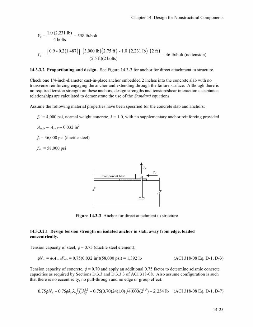
14.3.3.2 Proportioning and design. See Figure 14.3-3 for anchor for direct attachment to structure. Check one 1/4-inch-diameter cast-in-place anchor embedded 2 inches into the concrete slab with no transverse reinforcing engaging the anchor and extending through the failure surface. Although there is no required tension strength on these anchors, design strengths and tension/shear interaction acceptance relationships are calculated to demonstrate the use of the Standard equations. Assume the following material properties have been specified for the concrete slab and anchors: fc’ = 4,000 psi, normal weight concrete, λ = 1.0, with no supplementary anchor reinforcing provided Ase,N = Ase,V = 0.032 in2 fy = 36,000 psi (ductile steel) futa = 58,000 psi
Figure 14.3-3 Anchor for direct attachment to structure 14.3.3.2.1 Design tension strength on isolated anchor in slab, away from edge, loaded concentrically. Tension capacity of steel, φ = 0.75 (ductile steel element): φNsa = φ Ase,NFuta = 0.75(0.032 in2)(58,000 psi) = 1,392 lb (ACI 318-08 Eq. D-1, D-3) Tension capacity of concrete, φ = 0.70 and apply an additional 0.75 factor to determine seismic concrete capacities as required by Sections D.3.3 and D.3.3.3 of ACI 318-08. Also assume configuration is such that there is no eccentricity, no pull-through and no edge or group effect: 1.5 1.50.75 0.75 0.75(0.70)24(1.0) 4,000(2 ) 2,254 lbb c c efN k f hφ φ λ ʹ′= = = (ACI 318-08 Eq. D-1, D-7)
Component base
TuVu

FEMA P-751, NEHRP Recommended Provisions: Design Examples
14-26
The steel capacity controls in tension, so Section D.3.3.4 of ACI 318-08 is satisfied, but since there is no tension demand, the point is moot. 14.3.3.2.2 Design shear strength on isolated anchor, away from edge. Shear capacity of steel, φ = 0.65 (ductile steel element): φVsa = φ 0.6Ase,VFuta = 0.65(0.6)(0.032 in2)(58,000 psi) = 724 lb (ACI 318-08 Eq. D-1, D-19) Shear capacity of concrete, far from edge, limited to pry-out, no supplementary reinforcing, φ = 0.70: φVcp = φ kcpNcb = φ kcpNsa = φ kcpAse,Nfuta (ACI 318-08 Eq. D-1, D-4, D-30) φVcp = 0.70(1.0)(0.032 in2)(58,000 psi) = 1,299 lb The steel capacity controls in shear, with φVN = φVsa = 724 lb. Per Standard Section 13.4.2, anchors embedded in concrete or masonry must be proportioned to carry at least 1.3 times the force in the connected part due to the prescribed forces. Thus, Vu = 1.3(558) = 725 pounds, so the anchor is inadequate (mathematically), but would be deemed acceptable given the practical precision of engineering design. 14.3.3.2.3 Combined tension and shear. ACI 318-08 provides an equation (Eq. D-29) for the interaction of tension and shear on an anchor or a group of anchors:
1.2u u
N N
N VN Vφ φ
+ ≤ , which applies where either term exceeds 0.2
Since the tension demand, Nu, is zero, by inspection, this equation is also satisfied. 14.3.3.2.3 Summary. At each corner of the component, provide one 1/4-inch-diameter cast-in-place anchor embedded 2 inches into the concrete slab. Transverse reinforcement engaging the anchor and extending through the failure surface is not necessary.
14.3.4 Support on Vibration Isolation Springs 14.3.4.1 Prescribed seismic forces. Design forces for vibration isolation springs with the seismic stop gap clearance presumed to be greater than 1/4 inch are determined by an analysis of earthquake forces applied in a diagonal horizontal direction as shown in Figure 14.3-4. Terminology and concept are taken from ASHRAE APP IP. In the equations below, Fpv = Ev = 0.2SDSWp: Angle of diagonal loading:
-1tan ba
θ ⎛ ⎞= ⎜ ⎟
⎝ ⎠ (ASHRAE APP IP Eq. 17)
Tension per isolator:

Chapter 14: Design for Nonstructural Components
14-27
cos sin4 2
p pv puW F F h
Tb aθ θ− ⎛ ⎞
= − +⎜ ⎟⎝ ⎠
(ASHRAE APP IP Eq. 18)
Compression per isolator:
cos sin4 2
p pv puW F F h
Cb aθ θ+ ⎛ ⎞
= + +⎜ ⎟⎝ ⎠
(ASHRAE APP IP Eq. 19)
Shear per isolator:
4p
uF
V = (ASHRAE APP IP Eq. 20)
Figure 14.3-4 ASHRAE diagonal seismic force analysis for vibration isolation springs Select the worst-case assumption. Design for post-installed expansion anchors, requiring the use of Rp = 2.0 and nominal clearance between equipment and restraint greater than 1/4 inch.
Fp = ( ) ( )
0.4(2.5)(1.487) 3,000 lb1 2(1)
(2.0/1.0)+ = 6,692 lb (Standard Eq. 13.3-1)
h
a1 2 2 3b
F p sin (θ )W p
FPV FPV
W p
F p cos (θ )
1 2
XPlan view
X
Y Y
F p sin (θ )
F p cos (θ )θ
F p
4 3
F = Seismic horizontal forcePPW = Operating weight of equipment
PVF = Seismic vertical forcea = Distance between vibration isolators along Y-Yb = Distance between vibration isolators along X-Xh = Height of center of gravity = Vibration isolator location

FEMA P-751, NEHRP Recommended Provisions: Design Examples
14-28
1.6(1.487)(1.0)(3,000 lb)maxpF = = 7,138 lb (Standard Eq.13.3-2)
0.3(1.487)(1.0)(3,000 lb)
minpF = = 1,338 lb (Standard Eq. 13.3-3) Components mounted on vibration isolation systems must have a bumper restraint or snubber in each horizontal direction. Per Standard Table 13.6-1, footnote b, the design force must be taken as 2Fp if nominal clearance (air gap) between equipment and seismic restraint is greater than 0.25 inch. QE = 2Fp = 2(6,692 lb) = 13,384 lb (Standard Sec. 6.1.3) ρ = 1.0 (HVAC units are nonstructural components) (Standard Sec. 13.3.1) ρQE = (1.0)(13,384 lb) = 13,384 lb (horizontal earthquake effect) Fpv(ASHRAE) = 0.2SDSD = (0.2)(1.487)(3,000 lb) = 892 lb (vertical earthquake effect) D = Wp = 3,000 lb (vertical gravity effect) The above terms are then substituted into the Basic Load Combinations for Strength Design of Section 12.4.2.3 to determine the design member and connection forces to be used in conjunction with seismic loads. (1.2 + 0.2SDS) D + ρQE + L + 0.2S (Standard Basic Load Combination 5) (0.9 - 0.2SDS) D + ρQE + 1.6H (Standard Basic Load Combination 7) These seismic load effects can be used to determine bolt shear, Vu and tension, Tu (where a negative value indicates tension). In the calculations below, the signs of SDS and Fp have been selected to result in the largest value of Tu. U = (1.2 + 0.2SDS)D + ρQE
Tu = ( ) ( ) ( )( ) ( ) ( )1.2 3,000 lb – 892 lb 13,384 lb 2 ft cos 51.8 deg sin 51.8 deg- +
4 2 7 ft 5.5 ft⎡ ⎤⎢ ⎥⎣ ⎦
= -2,405 lb
Cu = ( ) ( ) ( )( ) ( ) ( )1.2 3,000 lb + 892 lb 13,384 lb 2 ft cos 51.8 deg sin 51.8 deg+ +
4 2 7 ft 5.5 ft⎡ ⎤⎢ ⎥⎣ ⎦
= 4,204 lb
Vu = 13,384 lb4
= 3,346 lb
U = (0.9 - 0.2SDS)D + ρQE
1 o7 fttan 51.85.5 ft
θ − ⎛ ⎞= =⎜ ⎟
⎝ ⎠

Chapter 14: Design for Nonstructural Components
14-29
Tu = ( ) ( ) ( )( ) ( ) ( )0.9 3,000 lb – 892 lb 13,384 lb 2 ft cos 51.8 deg sin 51.8 deg- +
4 2 7 ft 5.5 ft⎡ ⎤⎢ ⎥⎣ ⎦
= 2,630 lb
Cu = ( ) ( ) ( )( ) ( ) ( )0.9 3,000 lb + 892 lb 13,384 lb 2 ft cos 51.8 deg sin 51.8 deg+ +
4 2 7 ft 5.5 ft⎡ ⎤⎢ ⎥⎣ ⎦
= -3,980 lb
Vu = 13,384 lb4
= 3,346 lb
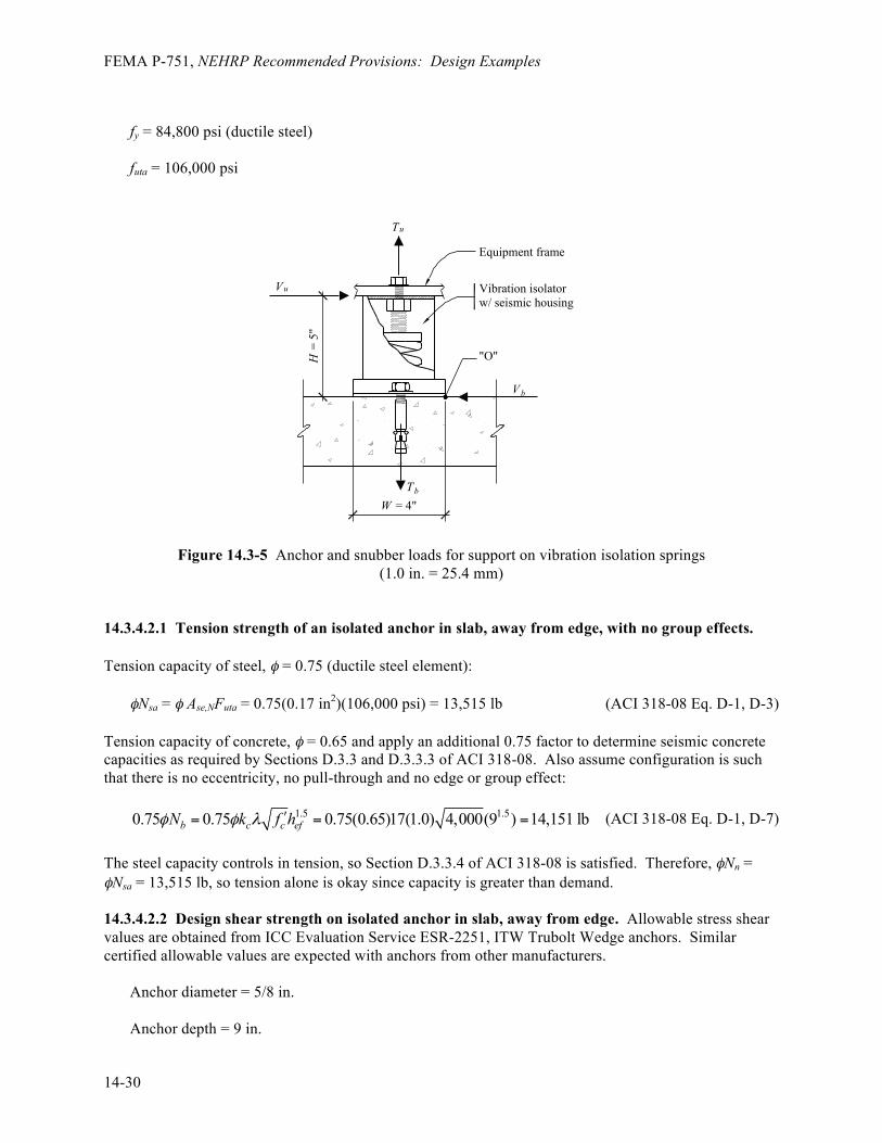
Note that the above values need to be multiplied by 1.3 per Section 13.4.2 to obtain the design values to be compared with design capacities. Therefore, the following values will be used for checking against design capacities of the post-installed anchors. Tension = 1.3(2,630 lb) = 3,419 lb Shear = 1.3(3,980 lb) = 5,174 lb 14.3.4.2 Proportioning and details. Anchor and snubber loads for support on vibration isolation springs are shown in Figure 14.3-5. Check the vibration isolation system within a housing anchored with one 5/8-inch-diameter post-installed wedge expansion anchors embedded 9 inches into the 10-inch-thick, 4,000 psi concrete housekeeping pad. The expansion anchors selected are specifically designed for seismic forces and have been tested for use in cracked concrete, following the procedures of ACI 355.2. Unless at least one of three conditions is satisfied, Standard Section 13.4.2 requires that the anchorage design forces be determined using Rp = 1.5. One of these conditions is that post-installed anchors be tested to verify their seismic capacity in accordance with the procedures of ACI 355.2. Since anchors selected for this example have been tested per ACI 355.2, this condition has been satisfied and anchorage design forces do not need to be modified and are those provided in Section 14.3.4.1 of this example. For the purpose of this example it is assumed that there are no edge effects or groups effects. Also, for this example the local prying effects of attachment members are assumed to be negligible. In most real cases these effects will exist and would either increase the design anchor force or reduce the capacity of the anchor. The Standard refers to ACI 318 to determine the capacity of anchors, including the design strength of post-installed expansion anchors. ACI 318 refers to the testing procedures of ACI 355.2-01 for verifying the seismic capacities of post-installed anchors. The ICC Evaluation Service provides testing procedures and acceptance criteria for post-installed anchors for both non-seismic and seismic applications. For nonstructural components, non-seismic post-installed anchors are permitted but are severely penalized. This example uses seismic anchors, which have been tested for use in cracked concrete and have ICC-ES reports approving their used for seismic applications consistent with the requirements of ACI 318 Appendix D and ACI 355.2. Assume the following material properties have been specified for the concrete slab and anchors: fc’ = 4,000 psi, normal weight concrete, λ = 1.0, with no supplementary anchor reinforcing provided For post-installed anchors, assume sleeves extend through shear plane Ase,N = Ase,V = 0.17 in2
FEMA P-751, NEHRP Recommended Provisions: Design Examples
14-30
fy = 84,800 psi (ductile steel) futa = 106,000 psi
Figure 14.3-5 Anchor and snubber loads for support on vibration isolation springs (1.0 in. = 25.4 mm)
14.3.4.2.1 Tension strength of an isolated anchor in slab, away from edge, with no group effects. Tension capacity of steel, φ = 0.75 (ductile steel element): φNsa = φ Ase,NFuta = 0.75(0.17 in2)(106,000 psi) = 13,515 lb (ACI 318-08 Eq. D-1, D-3) Tension capacity of concrete, φ = 0.65 and apply an additional 0.75 factor to determine seismic concrete capacities as required by Sections D.3.3 and D.3.3.3 of ACI 318-08. Also assume configuration is such that there is no eccentricity, no pull-through and no edge or group effect: 1.5 1.50.75 0.75 0.75(0.65)17(1.0) 4,000(9 ) 14,151 lbb c c efN k f hφ φ λ ʹ′= = = (ACI 318-08 Eq. D-1, D-7) The steel capacity controls in tension, so Section D.3.3.4 of ACI 318-08 is satisfied. Therefore, φNn = φNsa = 13,515 lb, so tension alone is okay since capacity is greater than demand. 14.3.4.2.2 Design shear strength on isolated anchor in slab, away from edge. Allowable stress shear values are obtained from ICC Evaluation Service ESR-2251, ITW Trubolt Wedge anchors. Similar certified allowable values are expected with anchors from other manufacturers. Anchor diameter = 5/8 in. Anchor depth = 9 in.
TbW = 4"
Vb
"O"
Tu
Vu
H =
5"
Vibration isolatorw/ seismic housing
Equipment frame

Chapter 14: Design for Nonstructural Components
14-31
fc' = 4,000 psi Shear capacity of steel, φ = 0.65: φVsa = φ 0.60Ase,V futa = 0.65(0.60)(0.17 in2)(106,000 psi) = 7,030 lb (ACI 318-08 Eq. D-1, D-19) Shear capacity of concrete, far from edge, limited to pry-out, no supplementary reinforcing, φ = 0.70: φ Vcp = φ kcpNcb = φ kcpNsa = φ kcp Ase,N futa (ACI 318-08 Eq. D-1, D-4, D-30) φ Vcp = 0.70(1.0)(0.17 in2)(106,000 psi) = 12,614 lb The steel capacity controls in shear, with φVN = φVsa = 7,030 lb 14.3.4.2.3 Combined tension and shear. ACI 318-08 provides an equation (Eq. D-32) for the interaction of tension and shear on an anchor or a group of anchors:
, which applies where either term exceeds 0.2
Substituting the demand and capacities computed above, one obtains: (3,419/13,515) + (5,174/7,030) = 0.99 which is less than 1.2 Therefore, the preliminary anchor design is okay. 14.3.4.2.4 Summary. At each corner of the HVAC fan unit, a proposed design provides a vibration isolation system within a housing anchored with one 5/8-inch-diameter post-installed expansion anchor embedded 9 inches into the concrete slab. When checked against the design loadings, these anchors work, but may not be practical in normal design situations. Other anchor configurations should be investigated, such as two anchors or four anchors per corner, which would reduce both the size of anchor and depth of embedment and required concrete pad thickness. Also, consideration should be given to requiring a limit of gap clearance to ¼ inch (which would require special inspection during construction to be sure it happened) to reduce design seismic forces on seismic restraints and associated anchorage.
14.3.5 Additional Considerations for Support on Vibration Isolators Vibration isolation springs are provided for equipment to prevent vibration from being transmitted to the building structure. However, they provide virtually no resistance to horizontal seismic forces. In such cases, some type of restraint is required to resist the seismic forces. Figure 14.3-6 illustrates one concept where a bolt attached to the equipment base is allowed to slide a controlled distance (gap) in either direction along its longitudinal axis before it contacts resilient impact material.
1.2u u
N N
N VN Vφ φ
+ ≤

FEMA P-751, NEHRP Recommended Provisions: Design Examples
14-32
Figure 14.3-6 Lateral restraint required to resist seismic forces Design of restraints for vibration-isolated equipment varies for different applications and for different manufacturers. In most cases, restraint design incorporates all directional capability with an air gap, a soft impact material and a ductile restraint or housing. Restraints should have all-directional restraint capability to resist both horizontal and vertical motion. Vibration isolators have little or no resistance to overturning forces. Therefore, if there is a difference in height between the equipment's center of gravity and the support points of the springs, rocking is inevitable and vertical restraint is required. An air gap between the restraint device and the equipment prevents vibration from transmitting to the structure during normal operation of the equipment. Air gaps generally are no greater than 1/4 inch. Dynamic tests indicate a significant increase in acceleration for air gaps larger than 1/4 inch. A soft impact material, often an elastomer such as bridge bearing neoprene, reduces accelerations and impact loads by preventing steel-to-steel contact. The thickness of the elastomer can significantly reduce accelerations to both the equipment and the restraint device and should be addressed specifically for life-safety applications. A ductile restraint or housing is critical to prevent catastrophic failure. Unfortunately, housed isolators made of brittle materials such as cast iron often are assumed to be capable of resisting seismic loads and continue to be installed in seismic zones. Overturning calculations for vibration-isolated equipment must consider a worst-case scenario as illustrated in Section 14.3.4.1. However, important variations in calculation procedures merit further discussion. For equipment that is usually directly attached to the structure or mounted on housed vibration isolators, the weight can be used as a restoring force since the equipment will not transfer a tension load to the anchors until the entire equipment weight is overcome at any corner. For equipment installed on any other vibration-isolated system (such as the separate spring and snubber arrangement shown in Figure 13.3-5), the weight cannot be used as a restoring force in the overturning calculations.
Gap GapEquipment
frameImpactmaterial
Steel bushingbolted or weldedto equipment frame

Chapter 14: Design for Nonstructural Components
14-33
As the foregoing illustrates, design of restraints for resiliently mounted equipment is a specialized topic. The Standard sets out only a few of the governing criteria. Some suppliers of vibration isolators in the highest seismic zones are familiar with the appropriate criteria and procedures. Consultation with these suppliers may be beneficial.
14.4 ANALYSIS OF PIPING SYSTEMS
14.4.1 ASME Code Allowable Stress Approach Piping systems typically are designed to satisfy national standards such as ASME B31.1. Piping required to be designed to other ASME piping codes uses similar approaches with similar definition of terms. 14.4.1.1 Earthquake design requirements. ASME B31.1 Section 101.5.3 requires that the effects of earthquakes, where applicable, be considered in the design of piping, piping supports and restraints using data for the site as a guide in assessing the forces involved. However, earthquakes need not be considered as acting concurrently with wind. 14.4.1.2 Stresses due to sustained loads. The effects of pressure, weight and other sustained loads must meet the requirements of ASME B31.1 Equation 11A:
0.75 1.0
4o A
L hn
PD iMS St Z
= + ≤
where: SL = sum of the longitudinal stresses due to pressure, weight and other sustained loads P = internal design pressure, psig Do = outside diameter of pipe, in. tn = nominal pipe wall thickness, in. i = stress intensification factor from ASME Piping Code Appendix D, unitless = 1.0 for straight pipe ≥ 1.0 for fittings and connections MA = resultant moment loading on cross section due to weight and other sustained loads, in-lb Z = section modulus, in3
Sh = basic material allowable stress at maximum (hot) temperature from ASME Piping Code
Appendix A For example, ASTM A53 seamless pipe and tube, Grade B: Sh = 15.0 ksi for -20 to 650 degrees Fahrenheit. 14.4.1.3 Stresses due to occasional loads. The effects of pressure, weight and other sustained loads and occasional loads including earthquake, must meet the requirements of ASME B31.1 Equation 12A:

FEMA P-751, NEHRP Recommended Provisions: Design Examples
14-34
0.75 0.75
4o A B
hn
PD iM iM kSt Z Z
+ + ≤
where: MB = resultant moment loading on cross-section due to occasional loads, such as from thrust loads,
pressure and flow transients and earthquake. Use one-half the earthquake moment range. Effects of earthquake anchor displacements may be excluded if they are considered in Equation 13A, in-lb.
k = duration factor, unitless. = 1.15 for occasional loads acting less than 10 percent of any 24-hour operating period. = 1.20 for occasional loads acting less than 1 percent of any 24-hour operating period. = 2.00 for rarely occurring earthquake loads resulting from both inertial forces and anchor
movements (per ASME interpretation). 14.4.1.4 Thermal expansion stress range. The effects of thermal expansion must meet the requirements of ASME B31.1 Equation 13A:
( )CE A h L
iMS S f S SZ
= ≤ + −
where: SE = sum of the longitudinal stresses due to thermal expansion, ksi. MC = range of resultant moments due to thermal expansion. Also includes the effects of earthquake
anchor displacements if not considered in Equation 12A, in-lb. SA = allowable stress range, ksi (per ASME B31.1 Eq. 1, ( )1.25 0.25A c hS f S S= + ). f = stress range reduction factor for cyclic conditions from the ASME Piping Code Table 102.3.2. Sc = basic material allowable stress at minimum (cold) temperature from the ASME Piping Code
Appendix A. 14.4.1.5 Summary. In the ASME B31.1 allowable stress approach, earthquake effects appear only in the MB and MC terms. MB represents earthquake inertial effects and MC represents earthquake displacement effects.
14.4.2 Allowable Stress Load Combinations
ASME B31.1 uses an allowable stress approach; therefore, allowable stress force levels and allowable stress load combinations should be used. While the Standard is based on strength design, Section 13.1.7 of the Standard permits the use of allowable stress design for nonstructural components where the reference document that is used for earthquake design of the component provides its acceptance criteria in terms of allowable stresses rather than strengths. For such cases, the allowable stress load combinations must consider dead, live, operating and earthquake loads in addition to those specified in the reference

Chapter 14: Design for Nonstructural Components
14-35
document. The earthquake loads determined in accordance with Standard Section 13.3.1 are multiplied by a factor of 0.7. Also, the allowable stress load combinations of Sections 2.4 and 12.4 of the Standard need not be used and the allowable stress increases for load combination which include seismic loads are permitted. Where earthquake effects are not considered, load combinations should be taken from the appropriate piping system design code. Section 13.1.7 also points out that the component and system must accommodate the relative displacements specified in Standard Section 13.3.2. 14.4.2.1 Standard allowable stress load combinations. The following allowable stress load combinations, specified in Standard Section 12.4.3, are permitted to be used in the design of nonstructural components. The load combinations have been adjusted to apply specifically to piping by deleting the terms F and H and substituting with Fp for QE. Other operational loads should be added using a load factor of 1.0. No increases in allowable stress are permitted for these load combinations: (1.0 + 0.14SDS)D + 0.7Fp (0.6 - 0.14SDS)D + 0.7Fp 14.4.2.2 Traditional allowable stress load combinations. The following allowable stress load combinations traditionally have been used in the design of many nonstructural components, including piping. Increases in allowable stress (typically 1/3) generally have been permitted for these combinations: (1.0 + 0.14SDS)D +0.7Fp (0.9 - 0.14SDS)D + 0.7Fp 14.4.2.3 Modified traditional allowable stress load combinations. It is convenient to define separate earthquake load terms to represent the separate inertial and displacement effects: EI = Earthquake horizontal inertial effects (MB term) EΔ = Earthquake displacement effects (MC term) It is also convenient to use the Traditional Allowable Stress Load Combinations modified to use ASME Piping Code terminology, deleting roof load effects (Lr or S or R) and multiplying by 0.75 to account for the 1.33 allowable stress increase where W or E is included. Only modified traditional allowable stress load combinations are considered in the discussion that follows. 0.75[(1.0 + 0.14SDS)D + L + S + 0.7(EI + EΔ)] 0.75[(0.9 + 0.14SDS)D + 0.7 (EI + EΔ)] By replacing EI with Fp, the following is obtained: 0.75[(1.0 + 0.14SDS)D + L + S + 0.7(Fp + EΔ)] 0.75[(0.9 + 0.14SDS)D + 0.7(Fp + EΔ)]

FEMA P-751, NEHRP Recommended Provisions: Design Examples
14-36
14.4.3 Application of the Standard 14.4.3.1 Overview. Piping systems are considered mechanical components. Mechanical component are exempt from the seismic requirements of Standard Chapter 13 under certain conditions, which are listed in Section 13.1.4. Furthermore, under certain conditions listed in Section 13.6.8, pipe supports are not required to be designed to the seismic requirements of Standard Chapter 13. There are many different types of piping systems. Standard Section 13.6.8.1 states that pressure piping designed in accordance ASME B31 is deemed to comply with the force, relative displacement and other requirements of the Standard and that elevator piping must be designed to ASME 17.1. Section 13.6.8.1 requires that the force and relative displacement requirements of Section 13.3.1 be used in lieu of specific force and displacement requirements of ASME B31. Fire sprinkler systems designed and installed in accordance with NPFA 13-2007 are deemed to comply with the force and displacement requirements of the Standard (see Provisions Section 13.6.8.2). Other piping is required to satisfy Standard Section 13.6.11, which refers to Sections 13.4, 13.6.5.3 and 13.6.5. Section 13.6.5 requires piping supports to be designed for the forces and displacements of Standard Sections 13.3.1 and 13.3.2. Section 13.4 provides special requirements for the design and detailing of anchorage that supports or anchors nonstructural components including piping. Standard Section 13.6.3 requires that mechanical components, including piping, that are assigned an Ip greater than 1.0 themselves be designed for the forces and displacements of Sections 13.3.1 and 13.3.2. Also, where Ip is greater than 1.0, the following additional requirements are imposed.
§ Provision must be made to eliminate seismic impact for components vulnerable to impact, for components constructed of nonductile materials and in cases where material ductility will be reduced (e.g., low temperature applications).
§ The possibility of loads imposed on components by attached utility or service lines due to
differential movement of support points on separate structures must be evaluated.
§ Where piping or HVAC ductwork components are attached to structures than could displace relative to one another and for isolated structures where the components cross the isolation interface, the components must be designed to accommodate the seismic relative displacements defined in Standard Section 13.3.2.
14.4.3.2 Forces. Standard Section 13.3.1 and Table 13.6-1 provide specific guidance regarding the equivalent static forces that must be considered in the design of piping systems. Note that the piping itself need only be designed for seismic forces and displacements if required by the reference standard (i.e., ASME 17.1, ASME B31.1, or NPFA-13) or if the value of Ip assigned to the piping is greater than 1.0. In computing the earthquake forces for piping systems, the inertial portion of the forces (noted as EI in this example) are computed using Standard Equations 13.3-1, 13.3-2 and 13.3-3. Depending on the type of piping system, the value specified for Rp ranges between 3 and 12 while the value of ap equals 2.5 for all values. For anchor points with different elevations, the average value of the Fp may be used, with minimum and maximum observed. In addition, the vertical effects should be considered, as illustrated in Section 14.4.2.
It is convenient to designate the term 0.211.4
DSS⎛ ⎞±⎜ ⎟
⎝ ⎠ by the variable β.

Chapter 14: Design for Nonstructural Components
14-37
The vertical component of EI can now be defined as βMa and applied to all load combinations that include EI. MB can now be defined as the resultant moment induced by the design force 0.7Fp, where Fp is as defined by Standard Equations 13.3-1, 13.3-2 and 13.3-3. 14.4.3.3 Displacements. Standard Section 13.3.2 provides specific guidance regarding the relative displacements that must be considered. Typically piping systems are designed considering forces and displacements using elastic analysis and allowable stresses for code prescribed wind and seismic equivalent static forces in combination with operational loads. However, no specific guidance is provided in the Standard except to say that the relative displacements should be “designed for”. The intent of this wording was not to require that a piping system remain elastic. Indeed, many types of piping systems typically are very ductile and can accommodate large amounts of inelastic strain while still functioning quite satisfactorily. What was intended was that the relative displacements between anchor and constraining points that displace significantly relative to one another be demonstrated to be accommodated by some rational means. This accommodation can be made by demonstrating that the pipe has enough flexibility or inelastic strain capacity to accommodate the displacement by providing loops in the pipeline to permit the displacement or by adding flex lines or articulating couplings which provide free movement to accommodate the displacement. Sufficient flexibility may not exist where branch lines may be forced to move with a ceiling or where other structural systems are connected to main lines. Often this “accommodation” is done by using engineering judgment, without calculations. However, if relative displacement calculations were required for a piping system, a flexibility analysis would be required. A flexibility analysis is one in which a pipe is modeled as a finite element system with commercial pipe stress analysis programs (such as Autopipe or CAESAR II) and the points of attachment are displaced by the prescribed relative displacements. The allowable stress for such a condition may be significantly greater than the normal allowable stress for the pipe. The internal moments resulting from support displacement may be computed by means of elastic analysis programs using the maximum computed relative displacements as described earlier and then adjusted. Adjustments should be in accordance with reference standards. 14.4.3.4 Load combinations. Combining ASME B31.1 Equations 12A and 13A with modified traditional allowable stress load combinations of Section 14.4.2.3 yields the following: For the modified traditional equation:
0.75 0.754
o A Bh
n
PD iM iM kSt Z Z
β ⎛ ⎞+ ± ≤⎜ ⎟
⎝ ⎠
( )CA h L
iM S f S SZ
≤ + −
and for the modified IBC Equation 16-18:
0.75 0.750.94
o A Bh
n
PD iM iM kSt Z Z
β ⎛ ⎞+ − ≤⎜ ⎟
⎝ ⎠

FEMA P-751, NEHRP Recommended Provisions: Design Examples
14-38
( )CA h L
iM S f S SZ
≤ + −
where: β = (1.0 + 0.105SDS) in the first equation and (0.9 - 0.105SDS) in the second equation. MA = the resultant moment due to weight (including pipe contents). MB = the resultant moment induced by the design force 0.7Fp where Fp is as defined by Standard
Equations 13.3-1, 13.3-2 and 13.3-3. MC = the resultant moment induced by the design relative seismic displacement Dp where Dp is as
defined in Standard Sections 13.3.3 and 13.6.3. SDS and Wp, are as defined in the Standard.
P, Do, tn, I, Z, k, Sh, SA, f and SL are as defined in ASME B31.1.
14.5 PIPING SYSTEM SEISMIC DESIGN
14.5.1 Example Description
This example illustrates seismic design for a portion of a piping system in an acute care hospital. It illustrates determination of the seismic demands on the system, consideration of anchorage and bracing of the system and design for system displacements within the structure and between structures. The example focuses on the determination of force and displacement demands on the different components of the system. The sizing of the various elements (braces, anchor bolts, etc.) are not covered in detail. The Standard provides requirements for three types of piping systems: ASME B31 pressure piping systems (Sec. 13.6.8.1), fire protection piping systems in accordance with NFPA 13 (Sec. 13.6.8.2 and 13.6.8.3) and other piping systems (Sec. 13.6.8.4). This example considers three piping runs of a chilled water piping system supported from the roof of a two-story structure. The system is not intended to meet the ASME 31 requirements and, therefore, is designed to the “other piping system” requirements of the Standard. The piping system is illustrated in Figures 14.5-1 and 14.5-2 and a typical trapeze-type support assembly is shown in Figures 14.5-3 and 14.5-4. One run of the piping system crosses a seismic separation joint to enter an adjacent structure. The building, located in the San Francisco Bay area of California, is assigned to Occupancy Category IV.

Chapter 14: Design for Nonstructural Components
14-39
Figure 14.5-1 Piping system
Figure 14.5-2 Piping system
1 2 3
A
B
Longitudingal Braces
Lateral Brace
Longitudingal Braces
Transverse Brace
Pipe Run "A" - 4 inch dia.Pipe Run "B" - 6 inch dia.Pipe Run "C" - 4 inch dia.
A-
-B Support 1 Support 2 Support 3
Support 5
Structural Separation Joint
Transverse Brace
Transverse Brace
Plan
4'-0" 40'-0" 40'-0"
2'-6
"
40'-0
"
1 2 3
Support 1 Support 2 Support 3
Support 4
Support M
Mechanical Unit
Roof
Level 2
Structural Separation Joint
Pipes "A", "B", and "C"Pipe "A"
Pipe "C"
Section
2'-6
"5'
-0"
7'-6
"

FEMA P-751, NEHRP Recommended Provisions: Design Examples
14-40
Figure 14.5-3 Typical trapeze-type support assembly
Figure 14.5-4 Typical trapeze-type support assembly
"A" "B" "C"1
1
Support 1-SectionA
2'-6
"
2'-6"
Support 1-SectionB
1
12'-6
"

Chapter 14: Design for Nonstructural Components
14-41
14.5.1.1 Earthquake design requirements. Earthquake design requirements for piping systems in the Standard depends on the system importance factor (Ip), the pipe diameter and the installation geometry. The importance factor is determined in Standard Section 13.1.3. Given that the structure is assigned to Occupancy Category IV, the components are assigned Ip = 1.5, unless it can be shown that the component is not needed for continued operation of the facility and failure of the component would not impair operations. Since failure of the piping system will result in flooding of the hospital, Ip = 1.5. Some piping is exempt from some or all of the seismic requirements, provided it meets the criteria in Sections 13.1.4 or 13.6.8. The user should refer to important errata in Standard Section 13.1.4, which addresses exemptions. The exemptions in Section 13.1.4 apply only to components with Ip = 1.0 and therefore are not applicable to this example. Section 13.6.8 waives seismic support requirements for piping supported by rods less than 12 inches long and for small-diameter high-deformability piping. Our example piping meets neither condition, so seismic supports will be required. "Other" piping systems must meet the following requirements of the Standard:
§ Section 13.4: Nonstructural Component Anchorage
§ Section 13.6.3: Mechanical Components
§ Section 13.6.5: Component Supports It is important to note that per Standard Section 13.6.3, where Ip is greater than 1.0, the component anchorage, bracing and the component itself (in this example, the pipe) must be designed to resist seismic forces. 14.5.1.2 System configuration. The portion of the piping system under consideration consists of three piping runs:
§ Piping Run “A”, a 4-inch-diameter pipe, which connects to a large mechanical unit at Line 1 supported at the second level. It crosses a seismic separation between adjacent structures at Line 3.
§ Piping Run "B", a 6-inch-diameter pipe, which has a vertical riser to the second level at Line 3.
§ Piping Run "C", a 4-inch-diameter pipe, which turns 90 degrees to parallel Line 3 at Column
Line 3-A.

FEMA P-751, NEHRP Recommended Provisions: Design Examples
14-42
Figure 14.5-5 Piping Run A
Figure 14.5-6 Piping Run B
ZMA
XMAM
1
2
3
Y1A
Z1A
X1A
load to transverse brace at support 1
Seismic Separation Joint
Y
X
Z
Pipe Run "A" - 4-inch dia.
Y1B
Z1B
X1B1
2
load to transverse brace at support 1
Pipe Run "B" - 6-inch dia.
Y
X
Z3
4

Chapter 14: Design for Nonstructural Components
14-43
Figure 14.5-7 Piping Run C The system consists of non-ASME B31 piping fabricated from steel Schedule 40 pipe with threaded connections. This example covers determination of the seismic forces acting on the system, a check of the seismically induced stresses in the pipes using simplifying assumptions, determination of bracing and anchorage forces and a check of the system for seismic relative displacements. It should be noted that details of pipe bracing systems vary according to the local preferences and practices of plumbing contractors. In addition, the use of proprietary pipe hanging and bracing systems is relatively common. As a result, this example concentrates on quantifying the prescribed seismic forces and displacements and on simplified stress checks of the piping system itself. After the seismic forces and displacements are determined, the bracing and anchorage connections can be designed and detailed according to the appropriate AISC and ACI codes.
14.5.2 Design Requirements.
14.5.2.1 Seismic design parameters and coefficients. ap = 2.5 for piping systems (Standard Table 13.6-1) Rp = 4.5 for piping not in accordance with ASME B31, constructed (Standard Table 13.6-1)
of high or limited deformability materials, with joints made by threading
SDS = 1.0 (for the selected location and site class) (given) Seismic Design Category = D (Standard Table 11.6-1) h = 30 feet (roof height) (given) hsx = 15 feet (story height) (given)
Y1C
Z1C
X1C1
2
5
load to transverse brace at support 1
Pipe Run "C" - 4-inch dia.
Y
X
Z3

FEMA P-751, NEHRP Recommended Provisions: Design Examples
14-44
z = 30 feet (system is braced at the roof level) (given)
30.0 ft 1.030.0 ft
zh= = (at roof)
Ip = 1.5 (Standard Sec. 13.1.3) Gravity (non-seismic) supports provided every 10'-0" (given) System working pressure (P) = 200 psi (given) ASTM A53 Pipe Fy = 35 ksi, threaded connections (given) D = Dead Load = Wp = 16.4 plf (4-inch-diameter water-filled pipe) (given) = 31.7 plf (6-inch-diameter water-filled pipe) Longitudinal brace spacing = 80 feet (given) According to Standard Section 13.3.1 (and repeated in Sec. 12.3.4.1), the redundancy factor does not apply to the design of nonstructural components. 14.5.2.2 Seismic design forces.
0.4(2.5)(1.0)
(1 2(1)) 1.004.51.5
pp p
WF W= + = (Standard Eq. 13.3-1)
1.6(1.0)(1.5) 2.40p p pF W W= = (Standard Eq. 13.3-2)
0.3(1.0)(1.5) 0.45p pF Wp W= = (Standard Eq. 13.3-3) 0.2(1.0) 0.2 0.2v pE D D W= = = (Standard Eq. 12.4-4) 14.5.2.3 Performance criteria. System failure must not cause failure of an essential architectural, mechanical, or electrical component (Standard Sec. 13.2.3). Component seismic attachments must be bolted, welded, or otherwise positively fastened without considering the frictional resistance produced by the effects of gravity (Standard Sec. 13.4). The effects of seismic relative displacements must be considered in combination with displacements caused by other loads as appropriate (Standard Sec. 13.3.2). The piping system must be designed to resist the forces in accordance with Standard Section 13.3.1 and must be able to accommodate movements of the structure resulting from response to the design basis ground motion, Dp.

Chapter 14: Design for Nonstructural Components
14-45
14.5.3 Piping System Design
The requirements for the design of the piping system are summarized in Table 13.2-1 of the Standard. The supports and attachments of all mechanical and electrical components must meet the requirements listed in Table 13.2-1. Where Ip > 1.0, the component itself must also meet these requirements. 14.5.3.1 Check of pipe stresses. The spacing of seismic supports is often determined by the need to limit stresses in the pipe. Therefore, the piping stress check is often performed first in order confirm the assumptions on brace spacing. For non-ASME B31 piping that is not subject to high operating temperatures or pressures, the stress check assumptions may be simplified. The pipes can be idealized as continuous beams spanning between lateral braces, while longitudinal forces can be determined using the length of pipe tributary to the longitudinal brace. The permissible stresses in the pipe are given in Standard Section 13.6.11, Item 2. For piping with threaded connections, the permissible stresses are limited to 70 percent of the minimum specified yield strength. The section properties of the Schedule 40 pipes are as follows: 4-inch diameter: Inner diameter, d1 = 4.026 in. Outer diameter, d = 4.5 in. Wall thickness, t = 0.237 in.
Plastic modulus, 33 3 31 (4.5) (4.026)
6 6 6 6ddZ = − = − = 4.31 in3
Moment of inertia, 4 4 4 4
10.049807( ) 0.049087((4.5) (4.026) )I d d= − = − = 7.23 in4 6-inch diameter: Inner diameter, d1 = 6.065 in. Outer diameter, d = 6.625 in. Wall thickness, t = 0.28 in.
Plastic modulus, 3 3(6.625) (6.065)
6 6Z = − = 11.28 in3
Moment of inertia, 4 40.049087((6.625) (6.065) )I = − = 28.14 in4

FEMA P-751, NEHRP Recommended Provisions: Design Examples
14-46
14.5.3.1.1 Gravity and pressure loads. The longitudinal stresses due to pressure and weight may be estimated using the following equation:
4
gL
MPdSt Z
= +
where: SL = sum of the longitudinal stresses due to pressure and weight P = internal design pressure, psig d = outside diameter of pipe, in. t = pipe wall thickness, in. Mg = resultant moment loading on cross section due to weight and other sustained loads, in-lb Z = section modulus, in3
Vertical supports are spaced at 10-foot centers, so the moment due to gravity, Mg, may be conservatively estimated as follows:
2 2(10) 12.58 8gDl DM D= = =
For a 4-inch-diameter pipe, where D = 16.4 plf: 12.5 12.5(16.4)gM D= = = 205 ft-lb = 2,460 in-lb
SL-DeadLoad = 2,4604.31
= 571 psi
Pr200(4.5)4(0.237)L essureS − = = 949 psi
For a 6-inch-diameter pipe, where D = 31.7 plf: 12.5(31.7)gM = = 396 ft-lb = 4,752 in-lb
4,75211.28L DeadLoadS − = = 421 psi
SL-Pressure = 1,183 psi 14.5.3.1.2 Seismic loads on Piping Runs A and C. By idealizing the piping runs as continuous beams, the maximum bending moments and reactions can be estimated readily.

Chapter 14: Design for Nonstructural Components
14-47
Piping Runs A and C are 4-inch-diameter pipes, shown schematically in Figures 14.5-5 and 14.5-7. They are idealized as a two-span continuous beam. The design lateral load, Fp, is taken as follows: 1.00 1.00(16.4)p pF W= = = 16.4 plf = w The maximum moment due to horizontal seismic load may be approximated as follows:
2 216.4(40)8 8EwlM = = = 3,280 ft-lb = 39,360 in-lb
The flexural stress associated with this moment is:
39,3604.31
Ebh
MfZ
= = = 9,132 psi
The moment due to vertical seismic load, Ev = 0.2 Wp, may be approximated as follows:
2 20.2(16.4)(10)8 8v
vE lM = = = 41 ft-lb = 492 in-lb
The flexural stress associated with this moment is:
4924.31
vbv
Mf Z= = = 114 psi
Note that for vertical seismic effects, the span of the pipe is taken as the distance between vertical supports, not the distance between lateral bracing. The basic strength load combination including earthquake effects from Standard Section 12.4.2.3 (based upon Standard Sec. 2.3.2) that will govern is Load Combination 5: U = (1.2 + 0.2SDS)D + 1.0ρQE + 0.5L + 0.2S For nonstructural components, ρ = 1.0 and QE = the forces (or stresses) resulting from applying Fp. In this example, live load, L and snow load, S, are equal to zero. The dead load, D, includes bending stress due to dead load. The load factor for internal pressure is the same as that for dead load. The design stress in the pipe is therefore: U = [1.2 + 0.2(1.0)](421 psi) + 1.2(1,183 psi) + 1.0(1.0)(9,132 psi) = 11,141 psi The permissible stress from Section 13.6.11, Item 2, of the Standard is 0.7Fy = 0.7(35,000) = 24,500 psi. Comparing the demand to capacity: U =11,141 psi < 0.7(35,000 psi) = 24,500 psi OK Note that a number of conservative assumptions were made for the sake of simplicity. A more precise analysis can be performed, where the piping is modeled to achieve more accurate bending moments and the effects of biaxial bending in the pipe are considered separately. Also note that at any point in the pipe

FEMA P-751, NEHRP Recommended Provisions: Design Examples
14-48
wall, the stresses caused by dead (and vertical seismic) load and by horizontal seismic load occur in different physical locations in the pipe. The peak stresses due to vertically applied load occurs at the top and bottom of the pipe, while the peak stress for horizontally applied load occurs at mid-height of the pipe. So assuming that they are both occurring in the same location and are algebraically additive is quite conservative. 14.5.3.1.3 Seismic loads on Piping Run B. Piping Run B, a 6-inch-diameter pipe, is shown schematically in Figure 14.5-6. It is idealized as a two-span continuous beam. Note that the effects of the 15-foot-high riser between Level 2 and the roof are considered separately. The design lateral load, Fp, is taken as follows: 1.00 1.00(31.7) 31.7p pF W= = = plf = w The maximum moment due to horizontal seismic load is approximated as follows:
2 231.7(40)8 8EwlM = = = 6,340 ft-lb = 76,080 in-lb
The flexural stress associated with this moment is:
76,08011.28
Ebh
MfZ
= = = 6,745 psi
The moment due to the vertical seismic load, Ev = 0.2 Wp, may be approximated as follows:
2 20.2(31.7)(10)8 8v
vE lM = = = 79.25 ft-lb = 951 in-lb
The flexural stress associated with this moment is:
95111.28
vbv
MfZ
= = = 84 psi
The design stress in the pipe is: U = [1.2 + 0.2(1.0)](571 psi) + 1.2(941 psi) + 1.0(1.0)(6,745 psi) = 8,674 psi < 24,500 psi OK
14.5.4 Pipe Supports and Bracing As with the design of the pipe itself, design of the vertical and lateral supports of piping systems can be simplified by making conservative assumptions. In this example, design demands on the support assembly at Support 1 (Figure 14.5-8) are determined.

Chapter 14: Design for Nonstructural Components
14-49
Figure 14.5-8 Design demands on piping support assembly 14.5.4.1 Vertical loads. Vertical pipe supports are often considered separately from lateral bracing. Configuration and spacing of vertical supports may be governed by plumbing codes or other standards and guidelines. Given that the vertical component of seismic force, Ev, is often low relative to other vertical loads, vertical supports proportioned for gravity and operational loads generally are adequate to resist the vertical seismic forces. However, where a support resists the vertical component of a lateral or longitudinal brace force, it should be designed explicitly to resist all applied forces. This example focuses on vertical supports associated with the lateral bracing system. Due to the repetitious nature of the pipe gravity support system, the vertical load at the brace assembly due to gravity or vertical seismic load can be estimated based on the tributary length of pipe. Given a 10-foot spacing of vertical supports, the vertical loads due to a 4-inch-diameter pipe are as follows: Dead load, Pv4 = (10 ft)(16.4 plf) = 164 lb Vertical seismic load, PEv4 = 0.2(10 ft)(16.4 plf) = 33 lb For a 6-inch diameter pipe: Dead load, Pv6 = (10 ft)(31.7 plf) = 317 lb Vertical seismic load, PEv6 = 0.2(10 ft)(31.7 plf) = 63 lb
f
e
g
Y
ZX
AB
C
30"
L17" L2
8" L47"
L28"
c
d
b
a
Z

FEMA P-751, NEHRP Recommended Provisions: Design Examples
14-50
14.5.4.2 Longitudinal lateral loads. Spacing of longitudinal bracing may be dictated by system geometry, thermal demands on the pipe, anchorage and brace capacities, or prescriptive limitations in standards and guidelines. In this example, we assume longitudinal braces are provided every 80 feet, which is twice the transverse brace spacing. For Piping Run A, the total length of pipe tributary to Support 1 is approximately 40 feet (half the distance between longitudinal braces at Supports 1 and 3) plus 9 feet (length of pipe from Support 1 to Support M, the mechanical unit), or 49 feet. The longitudinal seismic load, PX1A, for the 4-inch-diameter Piping Run A is: PX1A = (49 ft)(Fp) = (49 ft)(16.4 plf) = 804 lb For Piping Runs B and C, the total length of pipe tributary to Support 1 is approximately 80 feet. The longitudinal seismic load, PX1B, for the 6-inch-diameter Piping Run B is: PX1B = (80 ft)(Fp) = (80 ft)(31.7 plf) = 2,536 lb The longitudinal seismic load, PX1C, for the 4-inch-diameter Piping Run C is: PX1C = (80 ft)(Fp) = (80 ft)(16.4 plf) = 1,312 lb 14.5.4.3 Transverse lateral loads. To determine the transverse loads at support points, the pipes are idealized as continuous beams spanning between transverse braces. Assuming continuity over a minimum of two spans, the maximum reaction can be approximated conservatively as follows:
5(2)8wl
where w is the distributed lateral load and l is the spacing between transverse braces. For Piping Run A, we assume that 5/8 of the total length of pipe between the mechanical unit and the transverse brace at Support 2 is laterally supported at Support 1 (see Figure 14.5-3). The maximum transverse reaction due to Piping Run A at Support 1 may be approximated as follows:
15 58 8Z AP wl= = (16.4 plf)(40 ft + 9 ft) = 502 lb
For Piping Runs B and C, we assume that 5/8 of the total length of pipe on each side of Support 1 is laterally braced at Support 1 (see Figures 14.5-4 and 14.5-5). The maximum transverse reaction due to Piping Run B at Support 1 is then approximated as follows:
15 5(2) (2)8 8Z BP wl= = (31.7 plf)(40 ft) = 1,585 lb

Chapter 14: Design for Nonstructural Components
14-51
The maximum transverse reaction due to Piping Run C at Support 1 is approximated as follows:
15 5(2) (2)8 8Z CP wl= = (16.4 plf)(40 ft) = 820 lb
14.5.4.4 Support design. The bracing system at Support 1 is shown in Figure 14.5-8. The analysis must consider design of the following bracing elements: Beam f-g, Hangers f-b and g-d, Transverse Brace a-f and Longitudinal Braces f-c and g-e. The connections at a, b, c, d and e must also be designed and are subject to special requirements. 14.5.4.4.1 Beam f-g. Beam f-g is subject to biaxial bending under vertical (Y-direction) and longitudinal (X-direction) forces. The maximum moment, which occurs at the center, is equal to:
41
2 4 2CA B P LP L P LM = + +
The factored vertical loads for the piping runs are as follows: Piping Run A: PA = 1.2(164 lb) + 1.0(33 lb) = 230 lb Piping Run B: PA = 1.2(317 lb) + 1.0(63 lb) = 443 lb Piping Run C: PA = 1.2(164 lb) + 1.0(33 lb) = 230 lb The maximum moment about the x-axis of the beam due to vertical loads is:
230(7) 443(30) 230(7)2 4 2xM = + + = 4,933 in-lb
The vertical reactions at f and g are equal to (230 + 443 +230)/2 = 452 pounds. The factored lateral loads in the longitudinal direction determined in Section 14.5.4.2 are as follows: Piping Run A: PA = 804 lb Piping Run B: PA = 2,356 lb Piping Run C: PA = 1,312 lb The maximum moment about the y-axis of the beam due to lateral loads is:
804(7) 2,356(30) 1,312(7)2 4 2yM = + + = 25,076 in-lb
The horizontal reactions at f and g are:
2 3 4 4( ) 804(8 8 7) 2,356 1,312(7)2 30 2 30
A CBfP L L L P LPR
L L+ + + +
= + + = + + = 2,101 lb

FEMA P-751, NEHRP Recommended Provisions: Design Examples
14-52
1 2 31 ( ) 804(7) 2,356 1,312(7 8 8)2 30 2 30
CA Bg
P L L LP L PRL L
+ + + += + + = + + = 2,371 lb
Beam f-g would be designed for moments Mx and My acting simultaneously. 14.5.4.4.2 Brace design. By inspection, Brace g-e will govern the longitudinal brace design, since the horizontal reaction at g (2,371 lb) is larger than that at f (2,101 lb). The horizontal load that must be resisted by the Transverse Brace a-f is the sum of the loads from the three pipes determined in Section 14.5.4.3: Rz = 502 lb + 1,585 lb + 820 lb = 2,907 lb Assuming the same member will be used for all braces, Brace a-f governs the design. Since the brace is installed at a 1:1 slope (45 degrees), the maximum tension or compression in the brace would be: max max 2 (2,907)(1.414)zT C R= + = = 4,110 lb The brace selected must be capable of carrying Cmax with an unbraced length of ( )30 in. 2 = 42 inches. Bracing elements subject to compression should meet the slenderness ratio requirements of the appropriate material design standards. 14.5.4.4.3 Hangers. By inspection, Hanger f-b will govern the vertical element design, since the brace force in f-a governs the brace design. Since the brace is installed at a 1:1 slope (45 degrees), the maximum tension or compression due to seismic forces in the hanger is the same as the horizontal force resisted by the brace: 2,907 pounds. The vertical component of the brace force must be combined with gravity loads and the vertical seismic component. The maximum tension force in the hanger is determined using the basic strength Load Combination 5 from Standard Section 12.4.3.2 (based upon Standard Sec. 2.3.2): U = (1.2 + 0.2SDS)D + 1.0ρQE + 0.5L + 0.2S For nonstructural components, ρ = 1.0 and QE = the forces (or stresses) resulting from applying Fp. In this example, live load, L and snow load, S, are equal to zero. The unfactored reactions at f due to the weight of the water-filled pipes is 323 pounds. U = [1.2 + 0.2(1.0)](323 lb) + 1.0(1.0)(2,907 lb) = 3,359 lb The maximum compression force in the hanger is determined using the basic strength Load Combination 7 from Standard Section 12.4.2.3 (based upon Standard Sec. 2.3.2): U = (0.9 - 0.2SDS)D + 1.0 ρQE + 1.6H Substituting the values from above and noting that the lateral earth pressure load, H, is not applicable: U =[0.9 - 0.2(1.0)](323 lb) - 1.0(1.0)(2,907 lb) = -2,681 lb (tension)

Chapter 14: Design for Nonstructural Components
14-53
Fp should be applied in the direction which creates the largest value for the item being checked. A negative sign indicates compression. The hanger selected must be capable of carrying the maximum compression with an unbraced length of 30 inches. Again, bracing elements subject to compression should meet the slenderness ratio requirements of the appropriate material design standards. It is also important to note that the length of pipe that contributes dead load to counteract the vertical component of brace force is based on the spacing of the vertical hangers, not the spacing between lateral braces. 14.5.4.5 Anchorage design. Standard Section 13.4 covers the attachment of the hangers and braces to the structure. Component forces are those determined in Sections 13.3.1 and 13.3.2, with important exceptions. Anchors in concrete and masonry are proportioned to carry the least of the following:
§ 1.3 times the prescribed seismic design force, or
§ The maximum force that can be transferred to the connected part by the component structural system.
In addition, the value of Rp may not exceed 1.5 unless the anchors are prequalified for seismic loading or the component anchorage is governed by yielding of a ductile steel element. To illustrate the effects of these provisions, consider the design of the attachment to the structure at Point a in Figure 14.5-8. The horizontal and vertical components of the seismic brace force at Point a are 2,907 pounds each. Assuming the brace capacity does not limit the force to the anchor, the minimum design forces for the anchors is 1.3 times 2,907 pounds, which equals 3,779 pounds in tension acting currently with 3,779 pounds in shear. The maximum design force for the anchors, assuming that a ductile element does not govern the anchorage capacity and the anchor is not prequalified for seismic load, would be determined using an Rp = 1.5. Substituting Rp = 1.5 into the seismic force Equation 13.3-1, the following is obtained:
0.4(2.5)(1.0)
(1 2(1)) 3.001.51.5
pp p
WF W= + = (Standard Eq. 13.3-1)
In this case, the seismic maximum force of Equation 13.3-2, Fp = 2.40Wp, governs. This design force compares to the force of Fp = 1.00Wp obtained previously. The amplified design forces for the anchors would be 2.4/1.0 times 2,907 pounds, which equals 6,977 pounds in tension acting currently with 6,977 pounds in shear.
14.5.5 Design for Displacements
In addition to design for seismic forces, the piping system must accommodate seismic relative displacements. For the purposes of this example, we assume that the building has a 15-foot story height and has been designed for a maximum allowable story drift: 0.015 0.015(15)(12)a sxhΔ = = = 2.7 in. per floor 14.5.5.1 Design for displacements within structures. Piping Run A, a 4-inch-diameter pipe, connects to a large mechanical unit at Line 1 supported at the second level. Because the mechanical unit can be assumed to behave as a rigid body and the piping system is rigidly braced to the roof structure, the entire story drift must be accommodated in the 5'-0" piping drop (see Figure 14.5-2). There are several

FEMA P-751, NEHRP Recommended Provisions: Design Examples
14-54
approaches to accommodate the drift. The first is to provide a flexible coupling (articulated connections or braided couplings, for example). A second approach is to accommodate the drift through bending in the pipe. Loops are often used to make the pipe more flexible for thermal expansion and contraction and this approach also works for seismic loads. In this example, a straight length of a pipe is assumed. For a 4-inch-diameter Schedule 40 pipe, the moment of inertia, I, is equal to 7.23 in4. Assuming the pipe is fixed against rotation at both ends, the shear and moments required to deflect the pipe 2.7 inches are as follows: 3 312 / 12(29,000,000)(7.23)(2.7) / ((5.0)(12))aV EI l= Δ = = 31,451 lb M = (31,451 lb)(60 in.) = 1,887,060 in-lb
1,887,0604.31b
MfZ
= = 437,833= psi
These demands far exceed the capacity of the pipe and would overload the nozzle on the mechanical unit as well. Therefore, either a flexible coupling or a loop piping layout is required to accommodate the story drift. Piping Run B, a 6-inch-diameter pipe, drops from the roof level to the second level at Line 3. Again, the drift demand is 2.7 inches, but in this case, it may be accommodated over the full story height of 15 feet. A simplified analysis assumes that the pipe is fixed at the roof and second level. This assumption is conservative, since in reality the horizontal runs of the pipe at the roof and Level 2 provide restraint but not fixity. For a 6-inch-diameter Schedule 40 pipe, the moment of inertia, I, is equal to 28.14 in4. The shear and moments required to deflect the pipe 2.7 inches are as follows: 3 312 / 12(29,000,000)(28.14)(2.7) / ((15.0)(12))aV EI l= Δ = = 4,534 lb 2
VlM = =(4,534)((15.0)(12))/2 = 408,150 in-lb
The stress in the pipe displaced ∆ would be:
408,15011.28b
MfZ
= = 36,184= psi
This exceeds the permissible stress in the pipe, but not by a wide margin. In ASME B31.3, piping allowables are increased by a factor of 3 for stresses associated with seismic anchor movement relative displacements, but no such increases are currently provided for other piping. It is expected that threaded joints would be more highly stressed and a factor of 3 may not be conservative. Other options include refining the analysis to more accurately consider the effects of the rotational restraint provided by threaded couplings in the horizontal piping runs (which will tend to reduce the rigidity of the pipe and therefore reduce the bending stress), providing loops in the piping layout, or providing flexible couplings. 14.5.5.2 Design for displacements between structures. At the roof level, Piping Run A crosses a seismic separation between adjacent two-story structures at Line 3. Assuming story heights of 15 feet and design for a maximum allowable story drift for both buildings, the deflections of the buildings are: (2)0.015 (2)0.015(15)(12)xA xB sxhδ δ= = = 5.4= in.

Chapter 14: Design for Nonstructural Components
14-55
The displacement demand, DP is determined from Standard Equation 13.3-7 as follows:
max5.4 5.4p xA yBD δ δ= + = + 10.8= in.
In addition to motions perpendicular to the pipe, the seismic isolation joint must accommodate movement parallel to the pipe. Assuming a 12-inch seismic separation joint is provided, during an earthquake the joint could vary from 1.2 inches (if the structures move towards each other) to 22.8 inches (if the structures move away from each other). The flexible coupling, which could include articulated connections, braided couplings, or pipe loops, must be capable of accommodating this range of movements.
14.6 ELEVATED VESSEL SEISMIC DESIGN
14.6.1 Example Description
This example illustrates seismic design for a small platform-supported vessel in the upper floor of a structure. It includes determination of the seismic design forces, anchorage of the vessel to the supporting platform, design and anchorage of the platform and demands on the floor slab of the supporting structure. The example focuses on the determination of force and displacement demands on the different components of the support system. The sizing of the various elements (beams, columns, braces, connections, anchor bolts, etc.) are not covered in detail. This example considers a vessel supported by a platform on the second floor of a three-story structure. The contents of the vessel, a compressed non-flammable gas, are not hazardous. The structure, located in the Los Angeles area of California, is assigned to Occupancy Category II. The design approach for nonstructural components depends on the type, size and location of the component. The Standard provides requirements for nonstructural components in Chapter 13 and nonbuilding structures in Chapter 15. Vessels are classified as nonbuilding structures, but in this example the provisions of Standard Chapter 13 apply, due to the size and location of the vessel. 14.6.1.1 Earthquake design requirements. Earthquake design requirements for vessels in the Standard depend on the system importance factor (Ip), the mass of the vessel relative to that of the supporting structure and the installation geometry. There are special analytical requirements triggered by Section 13.1.5 where the weight of the nonstructural component exceeds 25 percent of the effective seismic weight of the structure. The example does not cover this condition. If that were the case, the component would be classified as a nonbuilding structure and the requirements of Section 15.3.2 would apply. The importance factor is determined in accordance with Standard Section 13.1.3. Given that the structure is assigned to Occupancy Category II, components are assigned Ip = 1.0, unless they must function for life-safety protection or contain hazardous materials. Neither of these conditions apply, so Ip = 1.0. 14.6.1.2 System configuration. The vessel is of steel construction and supported on four legs, which are bolted to a steel frame. A plan of the second level showing the location of the vessel is shown in Figure 14.6-1. A section through the structure showing the location of the vessel is presented in Figure 14.6-2. The supporting frame system consists of ordinary braced frames (tension-only bracing). An elevation of the vessel and supporting frame is shown in Figure 14.6-3.

FEMA P-751, NEHRP Recommended Provisions: Design Examples
14-56
Figure 14.6-1 Elevated vessel - second-level plan
6" R/C Slab
X
Y
30'-0"
12'-0" 6'-0" 12'-0"
30'-0
"
4'-6
"6'
-0"
4'-6
"15
'-0"

Chapter 14: Design for Nonstructural Components
14-57
Figure 14.6-2 Elevated vessel - section
Roof
Level 2
Level 1
Level 0
14'-0
"14
'-0"
18'-0
"
46'-0
"
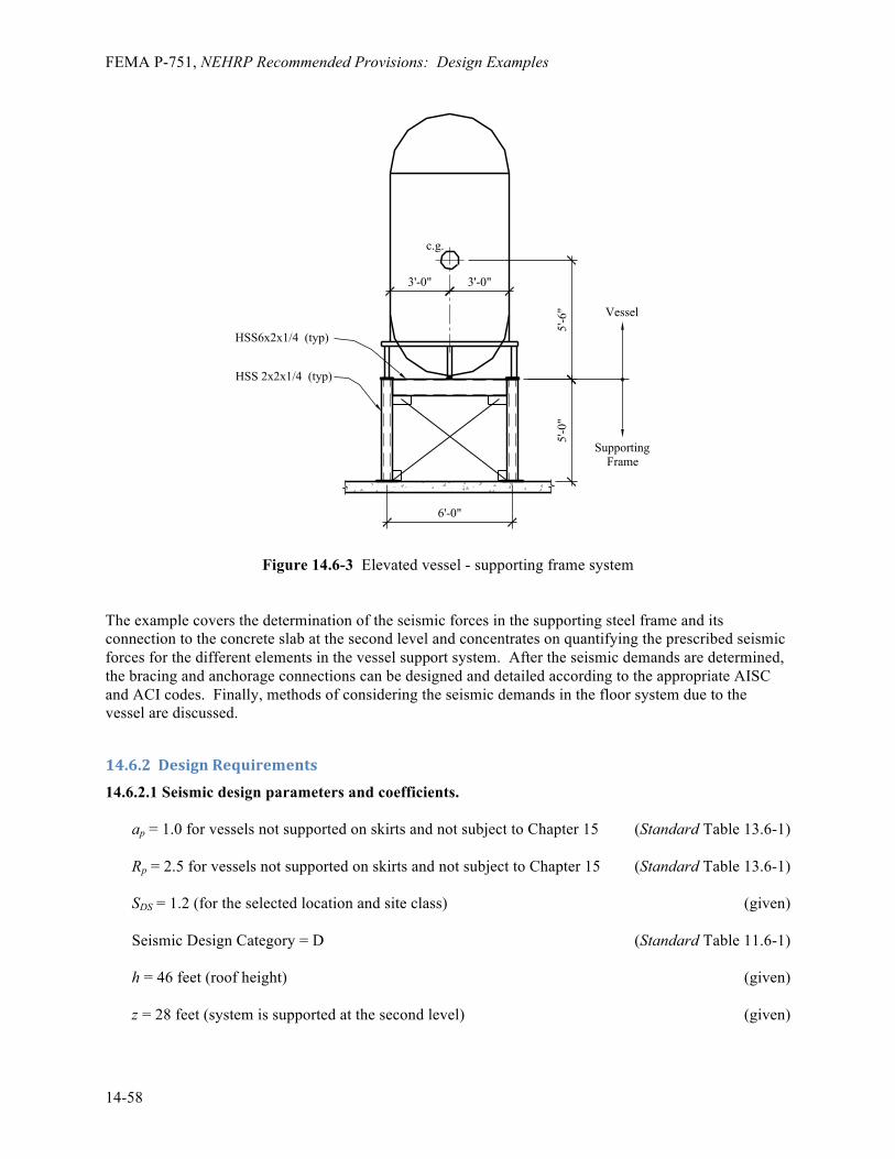
FEMA P-751, NEHRP Recommended Provisions: Design Examples
14-58
Figure 14.6-3 Elevated vessel - supporting frame system The example covers the determination of the seismic forces in the supporting steel frame and its connection to the concrete slab at the second level and concentrates on quantifying the prescribed seismic forces for the different elements in the vessel support system. After the seismic demands are determined, the bracing and anchorage connections can be designed and detailed according to the appropriate AISC and ACI codes. Finally, methods of considering the seismic demands in the floor system due to the vessel are discussed.
14.6.2 Design Requirements
14.6.2.1 Seismic design parameters and coefficients. ap = 1.0 for vessels not supported on skirts and not subject to Chapter 15 (Standard Table 13.6-1) Rp = 2.5 for vessels not supported on skirts and not subject to Chapter 15 (Standard Table 13.6-1) SDS = 1.2 (for the selected location and site class) (given) Seismic Design Category = D (Standard Table 11.6-1) h = 46 feet (roof height) (given) z = 28 feet (system is supported at the second level) (given)
HSS 2x2x1/4 (typ)
HSS6x2x1/4 (typ)
c.g.
3'-0" 3'-0"
5'-6
"5'
-0"
6'-0"
Vessel
SupportingFrame

Chapter 14: Design for Nonstructural Components
14-59
28.0 ft 0.60946.0 ft
zh= =
Ip = 1.0 (Standard Sec. 13.1.3) ASTM A500 Grade B steel HSS sections, Fy = 46 ksi, Fu = 58 ksi (given) ASTM A36 steel bars and plates, Fy = 36 ksi, Fu = 58 ksi (given) ASTM A53 Grade B pipe, Fy = 35 ksi, Fu = 60 ksi (given) ASTM A 307 bolts and threaded rods (given) D = Dead Load = Wp = 5,000 lb (vessel and legs) (given) = 1,000 lb (allowance, supporting frame) (given) According to Standard Section 13.3.1 (and repeated in Sec. 12.3.4.1), the redundancy factor does not apply to the design of nonstructural components. 14.6.2.2 Seismic design forces.
0.4(1.0)(1.2)
(1 2(0.609)) 0.4262.51.0
pp p
WF W= + = (Standard Eq. 13.3-1)
Maximum 1.6(1.2)(1.0) 1.92p p pF W W= = (Standard Eq. 13.3-2) Minimum 0.3(1.2)(1.0) 0.36p pF Wp W= = (Standard Eq. 13.3-3) 0.2(1.2) 0.24 0.24v pE D D W= = = (Standard Eq. 12.4-4) 14.6.2.2.1 Vessel. The seismic forces acting on the vessel are as follows: 0.426 0.426(5,000)p pF W= = = 2,129 lb 0.24 0.24(5,000)v pE W= = = 1,200 lb 14.6.2.2.2 Supporting frame. The seismic loads due to the supporting frame self-weight are as follows: 0.426 0.426(1,000)p pF W= = = 426 lb 0.24 0.24(1,000)v pE W= = = 240 lb 14.6.2.3 Performance criteria. Component failure must not cause failure of an essential architectural, mechanical, or electrical component (Standard Sec. 13.2.3).

FEMA P-751, NEHRP Recommended Provisions: Design Examples
14-60
Component seismic attachments must be bolted, welded, or otherwise positively fastened without considering the frictional resistance produced by the effects of gravity (Standard Sec. 13.4). The effects of seismic relative displacements must be considered in combination with displacements caused by other loads as appropriate (Standard Sec. 13.3.2). The component must be designed to resist the forces in accordance with Standard Section 13.3.1 and must be able to accommodate movements of the structure resulting from response to the design basis ground motion, Dp. Local elements of the structure, including connections, must be designed and constructed for the component forces where they control the design.
14.6.3 Load Combinations
The basic strength load combinations including earthquake effects from Standard Section 12.4.2.3 (based upon Standard Sec. 2.3.2) that will govern design of the vessel legs, attachments and the supporting frame are the following:
§ Load Combination 5: U = (1.2 + 0.2SDS)D + 1.0ρQE + 0.5L + 0.2S
§ Load Combination 7: U = (0.9 - 0.2SDS)D + 1.0 ρQE + 1.6H For nonstructural components, ρ = 1.0 and QE = the forces resulting from applying Fp. In this example, live load (L), snow load (S) and the lateral earth pressure load (H) are equal to zero.
14.6.4 Forces in Vessel Supports Supports and attachments for the vessel must meet the requirements listed in Standard Table 13.2-1. Seismic design of the vessel itself is not required, since Ip = 1.0. While the vessel itself need not be checked for seismic loading, the component supports listed in Standard Section 13.6.5 must be designed to resist the prescribed seismic forces. The affected components include the following:
§ The legs supporting the vessel
§ Connection between the legs and the vessel shell
§ Base plates and the welds attaching them to the legs
§ Bolts connecting the base plates to the supporting frame Standard Section 13.4.1 states that the lateral force, Fp, must be applied independently in at least two orthogonal directions. For vertically cantilevered systems, the lateral force also must be assumed to act in any horizontal direction. In this example, layout of the vessel legs is symmetric and there are two horizontal directions of interest, separated by 45 degrees. These two load cases are illustrated in Figure 14.6-4.

Chapter 14: Design for Nonstructural Components
14-61
Figure 14.6-4 Elevated vessel support load cases 14.6.4.1 Case 1 - moments about the y-y axis. The height of the vessel’s center-of-gravity above the bottom of the leg base plates is 5.5 feet. The moments about the bottom of these base plates are taken as follows: (5.5) (5.5)(2,129)pM F= = = 11,710 ft-lb Assuming the vessel acts as a rigid body, in Case 1 the overturning moments is resisted by the two legs along the x-x axis. The vessel is assumed to rotate about the legs on the y-y axis. The maximum tension and compression loads in the legs may be estimated as follows: /T C M d= = where the distance between legs A and C, d, is 6.0 feet. Therefore: 11,710 / 6.0T C= = = 1,952 lb The vertical load in each leg due to gravity is Wp/4 = 5,000/4 = 1,250 pounds. The shear in each leg due to Fp is V= Fp/4 = 2,129/4 = 532 pounds. 14.6.4.2 Case 2 - moments about the x'-x' axis. In Case 2 the overturning moments are resisted by all four legs, two in compression and two in tension. The loads in the legs due to gravity are the same as in Case 1, as is the shear in the legs due to Fp. Under seismic load, the vessel is assumed to rotate about the x'-x axis. The maximum tension and compression loads in the legs may be estimated as follows:
2(0.707 )
MT Cd
= =
x'
x'
y
y
xLoad Case 1
Load Case 2 Vessel Leg "A"Vessel Leg "C"
y'
y'
X
Y
x
Frame Leg "2"
Frame Leg "1"

FEMA P-751, NEHRP Recommended Provisions: Design Examples
14-62
where the distance between legs A and C, 0.707d , is 4.24 feet. Therefore: 11,710 / 2(4.24)T C= = = 1,380 lb
14.6.5 Vessel Support and Attachment
The axial loads in the vessel legs due to seismic overturning about the y-y axis (Case 1, in Section 14.6.4.1) are substantially larger than those obtained for overturning about the x'-x' axis (Case 2, in Section 14.6.4.2) . Therefore, by inspection Case 1 governs the design of the legs. The design compression loads on the vessel legs is governed by Load Combination 5: U = [1.2 + 0.2(1.2)](1,250 lb) + 1.0(1.0)( 1,952 lb) = 3,752 lb = CU The design tension load on the vessel legs is governed by Load Combination 7: U = [0.9 – 0.2(1.2)](1,250 lb) - 1.0(1.0)(1,952 lb) = -1,127 lb = TU (A negative sign denotes compression.) The design shear in each leg is U = 1.0(1.0)(532 lb) = 532 lb = VU. 14.6.5.1 Vessel leg design. The check of the leg involves a check of the connection between the vessel and the leg and a stress check of the leg itself. The length of the leg, L, is 18 inches and the legs are fabricated from 2-inch-diameter standard pipe. The section properties of the leg are as follows: A = 1.00 in2 Z = 0.713 in3 Assuming the leg is pinned at the connection to the supporting frame and fixed at the connection to the vessel, the moment and bending stress in the leg are as follows: M = VUL = 532(18) = 9,576 in-lb fb = M/Z = 9,756/0.713 = 13,683 psi The maximum axial compressive stress in the leg is: Cu/A = 3,752/1.00 = 3,752 psi The capacities of the leg and the connection to the vessel are determined using the structural steel specifications (AISC 360). The permissible strengths are as follows: Fa = 31,500 psi Fbw = 31,500 psi

Chapter 14: Design for Nonstructural Components
14-63
For combined loading:
1.0a bw
a bw
f fF F
+ ≤
3,752 13,683 0.553 1.031,500 31,500
+ = ≤
14.6.5.2 Connections of the vessel leg. The connection between the vessel leg and the supporting frame is shown in Figure 14.6-5. The design of this connection involves checks of the weld between the pipe leg and the base plate, design of the base plate and design of the bolts to the supporting frame. Load Combination 7, which results in tension in the pipe leg, will govern the design of the base plates and the bolts to the supporting frame. The design of the base plate and bolts should consider the effects of prying on the tension demand in the bolts.
Figure 14.6-5 Elevated vessel leg connection Each vessel leg is connected to the supporting frame by a pair of 5/8-inch-diameter bolts. The load path for this connection consists of the following elements: the weld of the leg to the connecting plate, the connecting plate acting in bending considering the effects of prying as appropriate, the bolts, the connection plate welded to the supporting frame beam and the welding of the connection plate to the supporting frame beam. Again by inspection, Case 1 (Section 14.6.4.1) governs. The factored loads in the connection are determined using Load Combinations 5 and 7 of Standard Section 12.4.2.3 (based upon Standard Sec. 2.3.2). As previously determined, the maximum compression in the connection (Load Combination 5) is: CU = 3,752 lb The maximum tension in the connection (Load Combination 7) is: U = (0.9 - 0.2SDS)D + 1.0ρQE + 1.6H
HSS6x2 beam
5/8"-diameter bolts
Vessel leg
1-1/2"
1-1/2" 1-1/2"

FEMA P-751, NEHRP Recommended Provisions: Design Examples
14-64
U = [0.9 – 0.2(1.2)](1,250 lb) - 1.0(1.0)(1,952 lb) = -1,127 lb (tension) = TU The maximum shear per bolt is: VU = 532 lb/2 = 266 lb The designs of the vessel leg base plate and of the connection plate at the supporting frame beams are identical. The maximum tension in each bolt is: TU = 1,127 lb/2 = 534 lb
The available shear and tensile strengths of the bolt are as follows: vrn = 5,520 lb (shear)
rn = 10,400 lb (tension)
Therefore, the bolts are adequate. The connection plates are 1/4 inch thick and 3 inches wide.
2 23(0.25)4 4bdZ = = = 0.0469 in3
The maximum moment in the plate is: MU = 534 lb (1.5 in.) = 801 in-lb The bending stress is: fb = MU /Z = 801/0.0469 = 17,088 psi OK Prying action can have the effect of increasing the tensile forces in the bolts. AISC 360 permits prying action to be neglected if the plate meets minimum thickness requirements, given by:
min4.44 '
u
TbtpF
=
where p = 3 inches is the tributary length per pair of bolts b' = (b-db/2) = (1.5-0.625/2) = 1.1875 in.
min4.44(534)(1.1875)
3(58,000)t = = 0.13 in.
This is less than the 0.25-inch thickness provided, so prying need not be considered further. The welds of the vessel leg to the vessel body and of the leg to the upper connection plate are proportioned in a similar manner. The calculation can be simplified by assuming the weld is of unit

Chapter 14: Design for Nonstructural Components
14-65
thickness. This yields a demand per inch of weld and an appropriate weld thickness can then be selected. The vessel leg has an outer diameter, d, of 2.38 inches. The weld properties for a weld of unit thickness are as follows:
3 32.386 6dZ = = = 2.25 in3
A = πd =3.14(2.38) = 7.45 in. The shear in the weld is: v = 532 lb/7.45 in. = 714 lb/in. The tension in the weld due to axial load is: T = 1,127 lb/7.45 in. = 151 lb/in. The tension to the weld due to bending (at the connection to the vessel) is: T = M/Z = 9,756/7.45 = 1,310 lb/in. For E70 electrodes, the capacity of a fillet weld is given by: Rn = 1.392 Dl (kips/in.) where D is the size of the weld in sixteenths of an inch and l is the weld length. For a unit length, a 3/16-inch fillet weld has a capacity of : Rn = 1.392(3)(1) = 4.18 kips/in. which will be adequate. The same size weld is used for the vessel leg-to-vessel body joint and for the leg-to-upper connection plate joint. A similar design approach is used to proportion the weld of the lower connection plate to the HSS 6x2 beam.
14.6.6 Supporting Frame
The design of the supporting frame can be performed separately from that of the vessel. The reactions from the vessel are applied to the frame and combined with the inertial loads resulting from the supporting frame itself. The configuration of the supporting frame is shown in Figure 14.6-6.

FEMA P-751, NEHRP Recommended Provisions: Design Examples
14-66
Figure 14.6-6 Elevated vessel supporting frame The supporting frame uses Steel Ordinary Braced Frames (OBF). While the supporting frame is designed for seismic forces determined in Section 13.3, the design process for the frame itself is similar to that used for building frames or nonbuilding structures similar to buildings. In this example, seismic loads are developed for the following elements:
§ Beams supporting the vessel legs
§ Braces
§ Columns supporting the platform and vessel
§ Base plates and anchor bolts To simplify the analysis, the self weight of the supporting frame is lumped at the vessel leg connection locations. 14.6.6.1 Support frame beams. The beams transfer vertical and horizontal loads from the vessel to the brace frames. The beams, fabricated from HSS6x2x1/4 members, are idealized as simply supported with a span of 6 feet. The reactions from the vessel legs are idealized as point loads applied at mid-span. The vertical loads applied to the beam are as follows: P = [5,000 lb (vessel) + 10,000 lb (frame)]/4 supports = 1,500 lb The lateral load per beam of the combined vessel and supporting frames is: V = 0.426[5,000 lb (vessel) + 10,000 lb (frame)]/4 supports = 639 lb The maximum load on a leg due to overturning of the vessel was computed as P = 1,952 pounds. The maximum factored vertical load, which will generate strong axis bending in the beam, is determined using Load Combination 5:
R1V
R1H R2H
R2V
3'-0" 3'-0"
5'-0"

Chapter 14: Design for Nonstructural Components
14-67
PU = [1.2 + 0.2(1.2)](1,500 lb) + 1.0(1.0)( 1,952 lb) = 4,112 lb = Pv Acting with the horizontal load, VU = 639 pounds. The moment in the beams then is: Mx-x = PUl/4 = (4,112 lb)(6.0 ft)/4 = 6,168 ft-lb My-y = VUl/4 = (639 lb)(6.0 ft)/4 = 959 ft-lb For an HSS6x2x1/4: Zx-x = 5.84 in3 Zy-y = 2.61 in3
1.0bybx
b b
ffF F
+ ≤
Fb = Fy = 0.9(46,000 psi) = 41,400 psi
6,168(12) / 5.84 959(12) / 2.61 0.41 1.041,400 41,400
by y y y ybx x x x x
b b b b
f M Zf M ZF F F F
− −− −+ = + = + = ≤ OK
14.6.6.2 Support frame braces. The maximum brace force occurs where loads are applied in the X- or Y-direction and the loads are resisted by two frames. The horizontal force is: V = 0.426[5,000 lb (vessel) + 10,000 lb (frame)]/2 braces = 1,278 lb The length of the brace is:
2 2(5) (6)+ = 7.81 ft
The force in the brace then is:
7.811,2786uT = = 1,664 lb (tension)
The braces consist of 5/8-inch-diameter ASTM A307 threaded rod. The nominal tensile capacity is: rn = 10,400 lb (tension) > 1,664 lb OK It is good practice to design the supporting frame connections to the same level as a nonbuilding structure subject to Chapter 15. In this example, the supporting frames would be treated as an ordinary braced frame. For this system, AISC 341 requires the strength of the bracing connection to be the lesser of the expected yield strength of the brace in tension, the maximum force that can be developed by the system, or the load effect based on the amplified load.

FEMA P-751, NEHRP Recommended Provisions: Design Examples
14-68
14.6.6.3 Support frame columns. The columns support the vertical loads from the vessel and frame, including the vertical component of the supporting frame brace forces. The columns are fabricated from HSS2x2x1/4 members and are idealized as pinned top and bottom with a length of 5 feet. The case where the vessel rotates about the x'-x' axis governs the design of the supporting frame columns. The overturning moment is: (10.5) (5.0) (10.5)(2,129) 5.0(426)p vessel p frameM F F− −= + = + 24,485= ft-lb Assuming the vessel acts as a rigid body, in Case 1 the overturning moment is resisted by the two legs along the y'-y' axis. The vessel is assumed to rotate about the legs on the x'-x' axis. The maximum tension and compression loads in the columns due to overturning may be estimated as follows: /T C M d= = where the distance between Frame Legs 1 and 2, (6.0) 2 8.48d = = feet. Therefore: 24,485 / 8.48 2,886T C= = = = 2,886 lb The vertical load in each leg due to gravity is Wp/4 = (5,000+1,000)/4 = 1,500 pounds. The design compression load on the supporting frame columns is governed by Load Combination 5: U = [1.2 + 0.2(1.2)](1, 500 lb) + 1.0(1.0)(2,886 lb) = 5,046 lb = CU The design tension load on the supporting frame columns is governed by Load Combination 7: U = [0.9 - 0.2(1.2)](1,500 lb) - 1.0(1.0)(2,886 lb) = -1,896 lb = TU The capacity of the HSS2x2x1/4 column is 38,300 pounds and is therefore adequate. 14.6.6.4 Support frame connection to the floor slab. The connection of the support frame columns to the floor slab includes the following elements:
§ Weld of the column and brace connection to the base plate
§ Base plate
§ Anchor bolts The design of the connection of the base plate and of the base plate itself follows the typical procedures used for other structures. There are special considerations for the design of the anchor bolts to the concrete slab that are unique to nonstructural components. Anchors in concrete and masonry must be proportioned to carry the least of the following:
§ 1.3 times the prescribed seismic design force, or
§ The maximum force that can be transferred to the connected part by the component structural system.

Chapter 14: Design for Nonstructural Components
14-69
The value of Rp may not exceed 1.5 unless the anchors are prequalified for seismic loading or the component anchorage is governed by yielding of a ductile steel element. The horizontal and vertical reactions of the supporting frame columns are as follows: CU = 5,046 lb
TU = -1,896 lb
VU = 1,278 lb
Assuming that no other element of the supporting frame limits the force to the anchor, the minimum design forces for the anchors would be 1.3 times 1,896 pounds, which is 2,465 pounds in tension, acting concurrently with 1.3 times 1,278 pounds, which is 1,661 pounds in shear. The maximum design force for the anchors, assuming a ductile element does not govern the anchorage capacity and the anchor is not prequalified for seismic load, would be determined using Rp = 1.5. Substituting Rp = 1.5 into the seismic force Equation 13.3-1 results in the following:
0.4(1.0)(1.2)
(1 2(0.609)) 0.711.51.0
pp p
WF W= + = (Standard Eq. 13.3-1)
This design forces compares to Fp = 0.426Wp obtained previously. The amplified overturning moment for the design of the anchors would be: (10.5) (5.0) (10.5)(0.71)(5,000) 5.0(0.71)(1,000)p vessel p frameM F F− −= + = + = 40,825 ft-lb
The corresponding tension load becomes: 40,825 / 8.48T = = 4,814 lb
The factored design tension is: U = [0.9 - 0.2(1.2)](1,500 lb) - 1.0(1.0)(4,814 lb) = -3,824 lb This is represents a 55 percent increase in the design tension. The amplified shear forces for the anchors would be (2.50/1.50)(1,278 lb), which is 2,130 pounds.
14.6.7 Design Considerations for the Vertical Load-‐Carrying System
This portion of the example illustrates design considerations for the floor slab supporting the nonstructural component. The floor system at Level 2 consists of a 6-inch-thick reinforced concrete flat-slab spanning between steel beams. To illustrate the effects of the vessel, the contribution of the vessel load to the overall slab demand is examined.

FEMA P-751, NEHRP Recommended Provisions: Design Examples
14-70
14.6.7.1 Slab design assumptions. Dead load = 100 psf Live load = 100 psf (non-reducible) 14.6.7.2 Effect of vessel loading. During design, the slab moments and shear are checked at different points along each span. In order to simply illustrate the potential effects of the vessel, this investigation will be limited to the change in the negative moments about the x-x axis over the center support. In an actual design, a complete analysis of the slab for the loads imposed by the vessel would be required. At the center support, the moments due to dead load and live load are as follows: Maximum dead load moment, MDL = wl2/8 = (100)(152)/8 = 2,813 ft-lb/ft Maximum live load moment, MLL = wl2/8 = (100)(152)/8 = 2,813 ft-lb/ft The support frame columns are 6 feet apart. Assuming an additional 3 feet of slab on each side of the frame to resist loads generated by the vessel, the design moments for the strip of slab supporting the vessel are as follows: MDL = 2,813 ft-lb/ft (12 ft) = 33,756 ft-lb MLL = 2,813 ft-lb/ft (12 ft) = 33,756 ft-lb The moments at the center support due to a point load, P, in one of the spans is:
( )24
PabM l al
= +
where:
a = distance from the end support to the point load b = distance from the point load to the center support l = span between supports = 15 ft
The point loads due to the vessel and support frame self weight is: P = 2(1,500 lb) = 3,000 lb The moment in the slab due to the vessel and support frame is as follows:
( )2 2(3,000)(4.5)(10.5) (3,000)(10.5)(4.5)15 4.5 (15 10.5)
4(15) 4(15)VDM = + + + = 7,088 ft-lb
The point loads due to the vessel and support frame caused by seismic in the Y-direction are as follows: 24,485 / 6.00T C= = = 4,081 lb

Chapter 14: Design for Nonstructural Components
14-71
The moment in the slab due to the overturning of the vessel and support frame for seismic forces in the Y-direction is:
( )2 2(4,081)(4.5)(10.5) ( 4,081)(10.5)(4.5)15 4.5 (15 10.5)
4(15) 4(15)VDM −= + + + = -1,286 ft-lb
or
( )2 2( 4,081)(4.5)(10.5) (4,081)(10.5)(4.5)15 4.5 (15 10.5)
4(15) 4(15)VDM −= + + + = 1,286 ft-lb
The factored moments for the slab without the vessel are: D + L: U = 1.2 D + 1.6 L = 1.2 (33,756 ft-lb) + 1.6(33,756 ft-lb) = 94,517 ft-lb The factored moments for the slab including the vessel are as follows: D + L: U = 1.2 D + 1.6 L = 1.2 (33,756 ft-lb+ 7,088 ft-lb) + 1.6(33,756 ft-lb) = 103,022 ft-lb The factored moments including seismic are as follows: Load Combination 5: U = (1.2 + 0.2SDS)D + 1.0ρQE + 0.5L + 0.2S = (1.2 + 0.2(1.2))(33,756+7,088) + 1.0(1.0)(1,286) + 0.5(33,756) + 0.2(0) = 76,979 ft-lb Load Combination 7: U = (0.9 - 0.2SDS)D + 1.0 ρQE + 1.6H = (0.9 - 0.2(1.2)) (33,756+7,088) + 1.0(1.0)(-1,286) + 1.6(0) = 25,671 ft-lb In this case, the loads from the vessel do not control the design of the slab over the center support.