Embed Size (px)
Citation preview

Design, Development and Optimization of Exhaust
System
Ishwang Gandhi*, Department of Automobile Engineering,
Indus Institute of Technology & Engineering,
Indus University.
Ahmedabad, Gujarat, India.
Prof. Suketu Y. Jani,
Assistant Professor, Department of Automobile Engineering,
Indus Institute of Technology & Engineering,
Indus University.
Ahmedabad, Gujarat, India.
* Corresponding Author
Abstract— Main focus of this dissertation is to Design and
Develop integrated catalytic converter and muffler, which is low
costing, using CAD Modeling Software & fabrication of the same.
Catalytic Converter is developed from metal oxides which are
readily available in the local market. Modern cars are equipped
with three way catalytic converters which are made from
Platinum Group Metals (PGM) and Cerium Oxide (CeO2) [1,2].
These days platinum is used as a lead catalyst in the catalytic
converter which is both costly and it agglomerates at working
temperature of catalytic converter [3]. Aim of this work is to use
metal oxides in place of the Platinum Group Metals (PGM) and
oxides which are required to import such as CeO2 and use
honeycomb structure formed by stacking hollow tubes made of
stainless steel one over another so as to increase the contact area
through which the exhaust gases pass and also causing laminar
flow of exhaust gases to take place through the hollow tubes [4] in
compare to conventional muffler in which resonating chambers
are used which are harmonically tuned to cause destructive
interference wherein opposite sound waves cancel each other out.
In this work catalytic converter is developed based on catalyst
material consisting of metal oxide namely kaolin (Al2O3•2SiO2)
and Urea (CO(NH2)2), in Wire Mesh substrate type. Here Urea is
used for reduction and Kaolin for oxidation of flue gases, in which
Urea replaces PGM.
Keywords - Catalytic Converter; CatCon; Muffler; Emission
Control; Exhaust System.
I. INTRODUCTION
A Catalytic Converter is a cylindrical unit about the size of a
small silencer and is installed into the exhaust system a vehicle
such as a car, scooter, moped, motorcycle or auto-rickshaw. It
is placed between the exhaust manifold and the silencer. Inside
the converter there is a honeycomb structure of a ceramic or
metal, which is coated with alumina base materials and
thereafter a second coating of precious metals platinum,
palladium or rhodium or combinations of the same. This
second coating serves as a catalyst. A catalyst is a substance
which causes a chemical reaction that normally does not
happen in the given conditions. As a result of catalytic
reaction, as the exhaust gases pass over the converter substrate,
toxic gases such as CO, HC and NOx are converted into
harmless CO2, H2 and N2. There are two types of catalytic
converters: 1) A two-way converter, which is used to control
only CO and HC emissions by oxidation. 2) A three-way
converter, which is used almost in all petrol cars. It controls
CO and HC by oxidation as well as NOx by reduction. Three-
way converters (TWC) are now commonly being used for
petrol engines and operate in two stages. The first converter
stage uses rhodium to reduce the NOx in the exhaust into
nitrogen and oxygen. In the second converter stage, platinum
or palladium acts as a oxidation catalyst to change HC and CO
into harmless water and CO2. For supplying the oxygen
required in the second stage, air is fed into the exhaust after the
first stage. The catalyst allows oxidation of the exhaust gases
at a much lower temperature than in the combustion chamber
[5]. The main components of catalytic converter are A)
Oxidation catalytic substrate B) Reduction catalytic substrate
C) Intumescent Mat Insulation Packaging D) Stainless Steel
Catalytic Converter body E) Lambda Sensor F) Heat Shield.
When the exhaust valve opens, high-pressure exhaust gas is
released, which causes a pressure wave in the air causing an
explosion. Since high pressure gases are released rapidly one
after the other in an engine, the explosion occurring very fast
combine together to form a steady noise. This noise consists of
different notes of various frequencies. The predominant notes
out of these have been found in two groups, viz., low
frequency notes from 50 to 500 Hz and high frequency notes
from 3,000 to 10,000 Hz. Thus any ideal silencer for absorbing
this noise must effectively reduce both the low and high
frequency notes. To reduce the noise, the engine exhaust is
connected via exhaust pie to silencer, which is also called
muffler. A tail pipe carries the exhaust gases from the muffler
to the rear or side of the vehicle near the rear wheel. Mufflers
used are of different types [6]. Muffler is engineered as an
acoustic soundproofing device designed to reduce the loudness
of the sound pressure created by the engine by way of acoustic
quieting.
II. DESIGN AND OPTIMIZATION
• In here, Fig. 1, shows the integral structure of the catalytic
converter and muffler which we fabricated. On the left side
is the catalytic converter with the stainless steel wire mesh
monolith structure on which catalysts will be doped.
• On the right hand side is the muffler, having honeycomb
structure made from hollow pipes to provide laminar flow
to flue gases and also have fins to give more air resistance
to flow of flue gases.
• The Designing (Modeling) of the model has been carried
out in PTC Creo 2.0 Parametric CAD Software developed
by Parametric Technology Corporation, USA and
Solidworks 2014 edition developed by Dassault Systèmes
SolidWorks Corp.
International Journal of Engineering Research & Technology (IJERT)
ISSN: 2278-0181http://www.ijert.org
IJERTV5IS020291
(This work is licensed under a Creative Commons Attribution 4.0 International License.)
Published by :
Vol. 5 Issue 02, February-2016
250
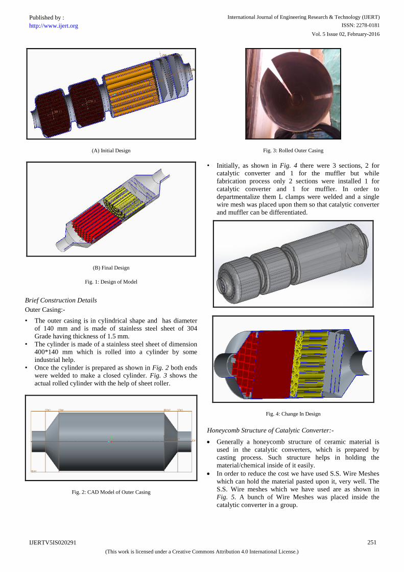
(A) Initial Design
(B) Final Design
Fig. 1: Design of Model
Brief Construction Details
Outer Casing:-
• The outer casing is in cylindrical shape and has diameter
of 140 mm and is made of stainless steel sheet of 304
Grade having thickness of 1.5 mm.
• The cylinder is made of a stainless steel sheet of dimension
400*140 mm which is rolled into a cylinder by some
industrial help.
• Once the cylinder is prepared as shown in Fig. 2 both ends
were welded to make a closed cylinder. Fig. 3 shows the
actual rolled cylinder with the help of sheet roller.
Fig. 2: CAD Model of Outer Casing
Fig. 3: Rolled Outer Casing
• Initially, as shown in Fig. 4 there were 3 sections, 2 for
catalytic converter and 1 for the muffler but while
fabrication process only 2 sections were installed 1 for
catalytic converter and 1 for muffler. In order to
departmentalize them L clamps were welded and a single
wire mesh was placed upon them so that catalytic converter
and muffler can be differentiated.
Fig. 4: Change In Design
Honeycomb Structure of Catalytic Converter:-
Generally a honeycomb structure of ceramic material is
used in the catalytic converters, which is prepared by
casting process. Such structure helps in holding the
material/chemical inside of it easily.
In order to reduce the cost we have used S.S. Wire Meshes
which can hold the material pasted upon it, very well. The
S.S. Wire meshes which we have used are as shown in
Fig. 5. A bunch of Wire Meshes was placed inside the
catalytic converter in a group.
International Journal of Engineering Research & Technology (IJERT)
ISSN: 2278-0181http://www.ijert.org
IJERTV5IS020291
(This work is licensed under a Creative Commons Attribution 4.0 International License.)
Published by :
Vol. 5 Issue 02, February-2016
251

Wire Meshes served as dual function one for oxidation
purpose and the second one for reduction purpose.
Fig. 5: Wire Meshes acting as Catalyst Substrate
Muffler:-
• Once the gases pass through the catalytic converter in the
given design it will enter in the muffler.
• Now as shown in Fig. 6 muffler also consists of two
sections first one being tubular structure to create a laminar
flow of the gases passing through it. Second being the
obstructions to create the turbulent flow of gases.
• Such kind of design creates an optimum amount of back
pressure which results in sound waves having shorter
magnitudes, thus noise level is reduced.
Laminar Flow Tubes For Muffler:
• Stainless Steel tubes having OD 5 mm and ID 2.5mm and
12.7 mm OD and 9.7 mm are placed parallel to each other
for steady distribution of exhaust and forming a laminar
flow. At the rear end, tubes have opening of 2.5 mm
creates maximum backpressure and increasing the flow
velocity at the outlet side. The length of the tubes is
100 mm.
Turbulence by Obstructions:
• Exhaust coming from the tubular pipes collides with the
primary curved section and pushes it away from the centre
and the secondary curve towards the centre. This
construction creates turbulence which decreases the sound
energy of exhaust gases.
Fig. 6: Cross section Of Muffler
III. FABRICATION
Welding the outer casing:
Tungsten Inert Gas (TIG) welding is preferred for welding
the Flat Stainless sheet which is rolled into circular shape with
the help of sheet roller to form the circular shape of the Outer
Casing, in which the wire mesh substrate of catalytic
converter, hollow tubes made of stainless steel are stacked to
form a honeycomb structure, and obstructions for increasing
back pressure will be placed and welded to inner side of the
casing.
Gas tungsten arc welding (GTAW), also known as tungsten
inert gas (TIG) welding, is an arc welding process that uses a
non-consumable tungsten electrode to produce the weld. The
weld area is protected from atmospheric contamination by an
inert shielding gas (argon or helium), and a filler metal is
normally used, though some welds, known as autogenous
welds, do not require it. A constant-current welding power
supply produces electrical energy, which is conducted across
the arc through a column of highly ionized gas and metal
vapors known as a plasma. GTAW is most commonly used to
weld thin sections of stainless steel and non-ferrous metals
such as aluminum, magnesium, and copper alloys [7].
In this research the base metal to weld is Stainless Steel
304 Grade Sheet metal of 1.5 mm thickness (Used to make, the
outer Casing, L-Clamps to hold the wire Mesh Substrate,
Obstructions), the filler material used is ER 304L as per AWS
Numbering System, and the shielding gas used is a
combination of C2 or 2% Carbon Dioxide and 98% Argon.
Argon/CO2 mix is used as it gives smooth finish as compared
to Argon/O2 mix. The Electrode used is Thoriated tungsten,
most common type of tungsten electrode for use on carbon and
stainless steel. The Thoriated tungsten starts readily and
maintains a stable arc. It has a greater resistance to
contamination and will maintain a sharp point and will not
break down as readily as pure tungsten [8]. All the figures,
Fig. 7 to Fig. 10 below shows the TIG welding process
carried out to make the prototype consisting of catalytic
converter and muffler enclosed in a single casing.
Fig. 7: Rolled S.S Sheet, Edges Welded to form Outer Casing
International Journal of Engineering Research & Technology (IJERT)
ISSN: 2278-0181http://www.ijert.org
IJERTV5IS020291
(This work is licensed under a Creative Commons Attribution 4.0 International License.)
Published by :
Vol. 5 Issue 02, February-2016
252

Fig. 8: Obstructions, (A) Obstructions Cut Outs (B) Welded Obstructions
Fig. 9: L-Clamps, (A) Strips to make Clamps (B) & (C) Welded L-clamps to Support wire Mesh Substrate
Fig. 10: Welding, (A) Spot Welding done to form Tapping (B) Completely Spot Welded Prototype (C) Finished Prototype with Weight
Catalyst preparation And fabrication:
The experimental methodology consists of two different parts:
1) Catalyst and substrate preparation and fabrication of
Catalytic converter, 2) Emission test. In this work only single
type of configuration is chosen for the work viz Wire mesh
substrate type. Method of preparation of above mentioned
configuration is disused below.
Wire mesh substrate catalyst
Material selection: Kaolin (Al2O3·2SiO2-Anhydrous) was used
as metal oxide catalyst. Pure urea (CH4N2O or CO(NH₂)₂) was used as reducing agent. With above listed oxidizing metal
oxide, urea was paired for the catalyst.
Catalyst slurry preparation: Sodium silicate (Na2O3Si)
solution was used in wash coat material to increase the coating
strength to surface of woven stainless steel substrate. And
carbide methyl cellulose (CMC) was added as a pore former.
80.0 grams of sodium silicate solution was added into 20·0 gm.
of metal oxide (Al2O3·2SiO2) to get 20% metal oxide slurry.
The slurry then was stirred well. 8.0 grams of CO(NH2)2 and
10·0 gm. of carbide methyl cellulose (CMC) was gradually
added. To ensure homogenization, it was milled for around 6·0
hours by using ball mill. Fig. 11(A) shows the prepared
catalyst slurry. The slurry reactor preparation was carried out
in accordance with Nijhuis et al. [9], and compared with
preparations for monolithic reactors described by Avila et al.
[10] and Haber [11]
Material selection for substrate: The substrate material is
stainless steel, as it is widely used in the automotive exhaust
system not only due to its advantages in mechanical and
physical properties but also low-cost [12]. The stainless steel
wire mesh of 20*20 size is selected for the economic purpose
was cut to Circular shape of Diameter 14 cm. prior to catalyst
coating. Fig. 11(B) shows the wire mesh substrates.
Wash coat material: Metal oxide (Kaolin), served dual
functions: an oxidation reduction catalyst and for the wash
coat. Kaolin has higher thermal stability and high durability.
This property is suitable for catalyst embedment or catalyst
[13].
Substrate coating: The stainless steel wire mesh will then
coated with the metal catalyst via dipping technique.
Fig. 11(C) shows coated wire meshes that are to be calcinated.
In this process stainless steel wire mesh was immersed into
prepared catalyst slurry for duration of 5 minutes. Then the
coated wire mesh was removed from catalyst slurry to be
blown using air blower. Until the unwanted residual catalyst
was evaded from the surface of the stainless steel wire mesh.
After blow process, coated stainless steel wire mesh was dried
in sunlight for two days before being calcinated in an open air
furnace [14].
Fig. 11: Wire mesh substrate catalyst, (A) Slurry Preparation (B) Wire mesh
Substrate (C) Slurry coated wire meshes
Calcination is a process in which a material is heated to a high
temperature without fusing, so that hydrates, carbonates, or
other compounds are decomposed and the volatile material is
expelled [15]. Calcinations take 6·0 hours at a temperature of
550°C with temperature ramping upon 10·0°C/min and holding
time of a 300 minutes [16]. Fig. 12 shows the Calcination
A
C
B
International Journal of Engineering Research & Technology (IJERT)
ISSN: 2278-0181http://www.ijert.org
IJERTV5IS020291
(This work is licensed under a Creative Commons Attribution 4.0 International License.)
Published by :
Vol. 5 Issue 02, February-2016
253

process carried out of wire mesh catalyst substrate. After the
Calcination process the stainless steel wire mesh were arranged
into straight bar to become a substrate for using as a catalytic
convert.
Fig. 12: Calcination Process, (A) Induction Heating Furnace For Calcination
(B) Control Panel of Furnace (C) Wire Meshes being Calcinated (D) Calcinated Wire Meshes (E) & (F) Wire Meshes after Removing excess
Catalytic Powder
Catalytic converter fabrication
Catalytic converter chamber: The fabrication catalytic
converter consist of few components, namely the converter
chamber, substrate. To avoid thermal optimization and design
validation, converter was made from Stainless Steel 304 Grade
Sheet Metal. The Catalytic Converter chamber was made by
rolling the S.S sheet and joining the edges by wielding. The
S.S wire mesh were placed inside the chamber and from both
the sides of Chamber L- Clamps were welded so as to support
the wire mesh substrate. Tapping’s at both the sides of
chamber were provided. One tapping was provided at the inlet
of the chamber so as to couple the chamber with the exhaust
manifold of the engine were as the Other tapping at the outlet
of chamber was made for the inserting the probe of the gas
analyzer. Coupler is provided at the inlet of the chamber, and
is glued with industrial Adhesive to inlet. This is shown in
Fig. 13.
Fig. 13: Tapping’s, (A) Inlet Tapping (B) Coupler glued at Inlet & L- clamp to
support wire Meshes (C) Exhaust Tapping
Substrate: The stainless steel wire mesh pieces were then
coated with metal catalyst before arranged into a straight bar.
The length of stainless steel wire mesh arrangement was
around 15·0 cm. A total of 50 pieces were used in an
arrangement for 15·0 cm length. The stainless steel wire mesh
substrate configuration is shown as in Fig 14.
Fig. 14: Stainless Steel Wire Mesh Substrate
A B
C D
F E
International Journal of Engineering Research & Technology (IJERT)
ISSN: 2278-0181http://www.ijert.org
IJERTV5IS020291
(This work is licensed under a Creative Commons Attribution 4.0 International License.)
Published by :
Vol. 5 Issue 02, February-2016
254

Costing:
Table 1 Cost/Price of Materials used in Research
Item Specifications Rate (Rs/-) Amount
(Rs/-)
Stainless
Steel Hollow
Tubes
(SS 304 &
202 Grade)
5 mm OD,
2.5 mm ID
40 Ft.
Length
12.7 mm OD,
9.5 mm ID,
16.7 Ft. Length
35Rs/Ft. 30Rs/Ft.
1400+5
02
=
1902/-
S.S Sheet +
S.S Tube
(SS 304
Grade)
1.5mm thickness
(Weight -4.4Kg),
2” Tube Diameter
260Rs/Kg 1144+300
= 1444/-
S.S Wire
Mesh
20*20 MeshSize
(20 Foot Length) 50Rs./ft 1000/-
Carboxy
Methyl
Cellulose
(CMC)
- 250Rs./500g 250/-
Urea - 200Rs/500gm Free
Kaolin Anhydrous 40Rs/400g 40/-
Sodium
Silicate Gel - 30Rs/kg Free
Araldite
Klear Epoxy Industrial Adhesive 45Rs/10g 45/-
Fabrication
Cost
Sheet Rolling, Pipe Cutting,
Grinding, TIG Welding -
200+29
0+200+
420
= 1110/-
Labour Cost - - 200/-
Induction
Heating Calcination Process 175Rs/Hour Free
Total 5991/-
IV. TESTING
The testing of the catalytic converter was done on Briggs and
Stratton engine used for BAJA Vehicles. It’s a 305cc, 10 HP,
OHV, 4 stroke, single cylinder, air cooled engine and runs on
petrol, shown in Fig. 15(A). Its petrol tank capacity is 2.5
liters. The experimental setup is shown in the Fig. 15(B)
below. As shown in Fig. 15(B), catalytic converter was
attached at the exhaust outlet of the engine through the coupler
so as to prevent the leakage of the exhaust gases. At the outlet
of muffler, probe was inserted to detect the exhaust gases and
readings were taken, as seen in Fig. 15(D),(F),(G). The testing
for the emissions emitted from the engine is done its idling
condition. The engine is cranked and with the help of
tachometer the RPM in the idling condition is measured i.e.
1900 rpm in no load condition, as seen in Fig. 15(C). The
testing has be done in two ways: 1) Without attaching the
catalytic converter, Fig. 15 and 2) With attaching catalytic
converter to the exhaust outlet of the engine, Fig. 16. The
testing has been done in the college lab and as well as at a
certified PUC Center.
Fig. 15: Testing without Attaching Catalytic converter, (A) Test Engine
(B) Experimental Setup (C) Idling RPM measurement (D) Inserting probe in the exhaust outlet of engine (E) Exhaust Gas Analyzer Machine (F) Reading
Of Exhaust Gases without attaching Catalytic converter (G) Readings
without attaching Catalytic converter at PUC Center
A
B
C D
E
F
G
International Journal of Engineering Research & Technology (IJERT)
ISSN: 2278-0181http://www.ijert.org
IJERTV5IS020291
(This work is licensed under a Creative Commons Attribution 4.0 International License.)
Published by :
Vol. 5 Issue 02, February-2016
255

Fig. 16: Testing with Attaching Catalytic converter, (A) Probe inserted in
Muffler outlet in college lab (B) Probe inserted in muffler outlet at PUC Center (C) Readings after attaching catalytic converter at PUC Center.
Since the oxygen sensor of exhaust gas analyzer failed in the
college lab, the readings after attaching the catalytic converter
couldn’t be obtained. Seeing the results obtained after
attaching the catalytic converter at PUC Center, inferences
were made that the chemical combination of metal oxide
(Kaolin) and Urea, failed in reducing the exhaust gases
emissions, and very steep rise was found in the values of HC,
CO and CO2 emissions, whereas decrease in the value of O2
emissions. Hence it can be deduced that the combination of
Kaolin and Urea fails in reducing the emissions of the engine.
V. RESULT
Based on the present experimental study, use of metal oxides
as catalyst in the catalytic converter for gasoline fuelled engine
were investigated as shown in Table 1 and following
conclusion were drawn:
Table 2 Experiment test result
As Per Bharat Stage 2 Complaint 4 Wheeler
Test
Gas Unit
Prescribed
Standard
Without
Converter
With
Converter
CO % Vol. 0.5 0.3 3.77
HC PPM 750 43 91
CO2 % Vol. NA 0.5 3.47
O2 % Vol. NA 19.82 11.44
Steep increase in CO emission volume by 3.47%, HC PPM
increase by 48 PPM and CO2 emissions by 2.97% and
reduction in O2 volume by 8.38% were observed at ideal
working temperature with the fabricated Catalytic converter,
Hence it can be deduced that above chemical combination of
metal oxide (Kaolin/Urea) used in this research was a
failure.
Engine Noise Reduction by 25-30 db.
ACKNOWLEDGMENT
Authors would like to thank Mr. Varun Pandit, Mr. Hetaksh
Patel, Mr. Keivaly Poojara, Colleagues of main author for
offering support and assistance in the research of this paper
that has driven us in efforts. We would like to express our
sincere thanks to Prof. Sujoy Chaudhury, Head of the
Department, Metallurgy Department, Indus University and
Dinesh R. Soni, Jayesh K. Khasia, Lab Assistants of
Metallurgy Department, Indus University for providing the
facilities, guidance and helping us in clearing our doubts
regarding the Research work. Their experience has been our
motivation while carrying out the Research. We would like to
extend our thanks to Shree Bhavani Heat Treaters, GuruKrupa
Industries, Happy Food Inc., Associate Petrol Pump Private
Limited & Vidhi Industries for their obligation over Industrial
and Manufacturing Help and Co-operation throughout our
work.
REFERENCES
[1] Osawa, M.: Role of cerium–zirconium mixed oxides as catalysts for car pollution: a short review. J. Alloy. Compd. 27(5), 886–890 (1998)
[2] Kaspar, J.; Fornasiero, P.; Graziani, M.: Use of CeO2-based oxides in the three-way catalysis. Catal. Today. 50, 285–298 (1999)
[3] Poulopoulos, S.G.; Philippopoulos, C.J.: MTBE, methane, ethylene and regulated exhaust emissions from vehicles with deactivated catalytic converters. Atmos. Environ. 38, 4495–4500 (2004)
[4] Harshal C. Kuttarmare, Vishal D. Ramteke, Nirmal H. Pandey,: The Conversion of Fluid Flow into Laminar Flow Device, International Journal of Emerging Engineering Research and Technology Volume 2, Issue 2, May 2014, PP 50-53
[5] Dr. Kirpal Singh, Automobile Engineering, 11th ed., vol. 2., Standard Publishers Distributors, 2009, pp. 479-480.
[6] Dr. Kirpal Singh, Automobile Engineering, 11th ed., vol. 2. Standard Publishers Distributors, 2009, pp. 119-120.
[7] S.K. Hajra Choudhury, A.K. Hajra Choudhury, Nirjhar Roy, Elements Of Workshop Technology Vol. 1 Manufacturing Processes, 14th ed., vol. 1, Media Promoters & Publishers Pvt. Ltd., 2010, pp. 236-237.
[8] http://www.thefabricator.com/article/arcwelding/the-fundamentals-of-gas-tungsten-arc-welding--preparation-consumables-and-equipment-necessary-for-the-process
[9] Nijhuis, T.A.; Beers, A.E.W.; Vergunst, T.; Hoek, I.; Kapteijn, F.; Moulijn, J.A.: Preparation of monolithic catalysts. Catal. Rev. 43(4), 345–380 (2001)
[10] Avila, P.; Montes, M.; Miro, E. E.: Monolithic reactors for environmental applications a review on preparation technologies, Chem. Eng. J., 109, 11–36 (2005)
[11] Haber, J.: Manual on catalyst characterization. J. Pure Appl. Chem. 63(9), 1227–1246 (1991)
[12] Bode, H.; Maus, W.; Swars, H.: How metal substrate are able to have an influence on converter efficiency, In: Presented at 17th International Engine Symposium, 25–26th April, Vienna (1996)
[13] Alois, F.; Active metal: preparation characterization application, Wiley VCH, New York (1995)
B
A
C
International Journal of Engineering Research & Technology (IJERT)
ISSN: 2278-0181http://www.ijert.org
IJERTV5IS020291
(This work is licensed under a Creative Commons Attribution 4.0 International License.)
Published by :
Vol. 5 Issue 02, February-2016
256

[14] Qurayshi Shahidurrehman H., Shaikh Mohammad Salman Y., Ghanchi Mohammed Ameen A., A Project Report on “Development & Improvement of catalytic convertor for petrol fuelled engine”, Indus Institute of Technology & Engineering, Gujarat Technological University, Ahmedabad, November 2012, pp. 22-25, unpublished.
[15] http://www.lenntech.com/chemistry/calcination.htm
[16] Md. Abul Kalam, Masjuki Hj Hassan: Design, Modification and Testing of a Catalytic Converter for Natural Gas Fueled Engines, Arabian Journal for Science and Engineering 36:677–688 (2011)
International Journal of Engineering Research & Technology (IJERT)
ISSN: 2278-0181http://www.ijert.org
IJERTV5IS020291
(This work is licensed under a Creative Commons Attribution 4.0 International License.)
Published by :
Vol. 5 Issue 02, February-2016
257