Embed Size (px)
Citation preview

Rese
Design
arch House Design Decision-making Process 1
Produced by the Department of Public Works and the Department of Housing
April 2005
Decision-Making Process

Research House Design Decision-making Process 2
Table of contents INTRODUCTION ............................................................................................................... 3 1. BRIEF............................................................................................................................ 4 2. SITE SELECTION ......................................................................................................... 5
2.1 Site evaluation
2.2 Site selection
3. SITE ANALYSIS ........................................................................................................... 8
3.1 Geographic location and site orientation
3.2 Site features
3.3 Council requirements
3.4 Character 4. KEY DESIGN ISSUES ................................................................................................ 12
4.1 Site drainage and water issues
4.2 Display home issues
4.3 Key brief requirements 5. PRELIMINARY DESIGN.............................................................................................. 14
5.1 Site zoning 6. DESIGN AND PLANNING........................................................................................... 18
6.1 Plan zoning
6.2 Sketch plan one
6.3 Sketch plan two
6.4 Sketch plan three
6.5 Sketch plan four 7. DESIGN DEVELOPMENT STRATEGIES ................................................................... 23
7.1 Universal design strategy
7.2 Safety strategy
7.3 Security strategy
7.4 Passive design strategy
7.5 Energy strategy
7.6 Water use strategy
7.7 Maintenance strategy

Research House Design Decision-making Process 3
8. DESIGN DEVELOPMENT ........................................................................................... 32
8.1 Sleeping/services zone
8.2 Living/ancillary zone
8.3 Kitchen design
8.4 Storage
8.5 Landscaping 9. BUILDING ELEMENTS .............................................................................................. 39
9.1 Use masonry forms and walls
9.2 Glazing
9.3 Slab on ground construction
9.4 Roof and ceiling
9.5 Textures and colours 10. FINAL DESIGN ........................................................................................................ 43 APPENDIX A � SMART HOUSING................................................................................. 45 APPENDIX B � SITE HISTORY ...................................................................................... 48 APPENDIX C � REFERENCES AND BIBLIOGRAPHY ................................................. 49 APPENDIX E � PROJECT DESIGN BRIEF ................................................................... 59

Research House Design Decision-making Process 4
Introduction The Department of Housing and the Department of Public Work�s Towards Healthy and Sustainable Housing Research Project, commonly known as Research House, is an essential part of the Smart Housing initiative to promote social, economic and environmental sustainability in housing design and construction. Located in Rockhampton in central Queensland, the Research House project investigates building homes which are more user friendly, comfortable, affordable and environmentally responsible. With the support of private and public sector sponsors, the project involved the design, construction and monitoring of a four-bedroom house which is home to a family of two adults and two teenagers. Research House brings together new and innovative design concepts, technologies and products, and tests them in a single living environment. The research results will aim to inform Queenslanders on how housing can be improved. A three-year research period which commenced in December 2002, is investigating water use, energy use and thermal issues in Research House. The qualitative and quantitative research results will give valuable insight into the effectiveness of Smart Housing design in practice, and will help to shape the future direction of housing in Queensland. Prior to the construction of the house, an extensive design decision-making process was undertaken for the period June 2000 to December 2000. This process recorded the progress made through the design phases of the project, the decisions reached and the strategies used. The following document captures the most critical aspects of the decision-making process that are likely to be of interest to readers. Project team The project was commissioned by the Department of Housing, who managed the project overall with the Department of Public Works. The Department of Public Works were involved in the project management (Built Environment Research Unit), design (Project Services) and construction (Q Build, Capricornia region) of Research House.

Research House Design Decision-making Process 5
The Towards Healthy and Sustainable Housing research project brief specified that a four-bedroom, slab-on-ground house of composite construction be built with a five star energy rating.1 An initial project construction budget of $180,000 was allocated for the project. The aim of the project was to build and demonstrate a home which reflected the expectations of the private sector market, included design aspects used in the Department of Housing�s housing programs and promoted the Smart Housing initiative�s design principles. The house was not specifically designed for a predetermined client or to be tenanted by the Department of Housing. The project was developed as �an important housing research component as part of the Smart Housing concept� (see Appendix A). The key design considerations of the house incorporate the Smart Housing triple bottom line approach to sustainability: • social sustainability - universal design, safety, security and healthy housing; • environmental sustainability - resource efficient in terms of waste, water and energy,
incorporating passive solar design and energy-smart building practices; • economic sustainability - cost-efficient over time. These key design considerations are detailed in the objectives of the project, which are to: • facilitate research in ecological building design and construction; • incorporate passive design; • adopt energy conservation measures; • utilise recycled materials where possible; • adopt water conservation measures; • maximise ventilation potential; • demonstrate social sustainability principles such as universal design, safety and security; • adopt resource management strategies; and • minimise the presence of volatile organic compounds (VOC�s). Industry and product manufacturers were offered sponsorship opportunities to showcase their products in Research House, and in accordance with the brief, the house was opened to the public for a minimum period of 12 weeks. In addition to the key design considerations, the brief stipulated a number of design elements which restricted the range of some design decisions in regard to areas such as roof forms, ceiling heights, floor and wall construction types, individual room requirements and furniture. The design process for the project was challenging due to the number of objectives and constraints outlined in the brief and in relation to the site.
1 The energy rating is calculated using the Building Energy Rating Scheme (BERS) thermal performance computer model.
1. BRIEF

Research House Design Decision-making Process 6
2. SITE SELECTION Five sites were considered during the site selection process for Research House. These sites included available land from the Department of Housing�s existing land bank, north and south Rockhampton sub-divisions and undeveloped land available on the south side of Rockhampton. To assist in the decision-making, a range of considerations were discussed. An early front-runner in the site selection process was a site in Campbell Street. This site was initially considered suitable and site evaluation commenced to compare it against other available sites. Issues that were raised in the evaluation of this site included the fact that the site was: • zoned as Zone B for high density development; • adjoined to a semi-industrial area; • adjacent to a main road; • subject to lane-way widening policy by local council; and • subject to sewer bridging requirements for a sewer main through the middle of the block. It was determined that this block may be more valuable for high-density development and the decision was made that another site would need to be identified since none of the alternative sites were comparing well in early site evaluations. A second site in Campbell Street was subsequently identified for further evaluation. The following site evaluation methodology lists the critical issues identified, demonstrates how the sites were compared and the criteria used. It also identifies additional advantages of the selected site which were not part of the evaluation process. 2.1 Site evaluation The site evaluation aimed to comparatively analyse the five sites under consideration in relation to the brief and the Department of Housing�s Smart Housing criteria. Specific requirements were identified for the selection criteria listed below: • site location, including display house considerations; • orientation, including prevailing breezes and solar path; • infrastructure, including public transport, shopping, schooling, employment and service access
considerations; • public utilities; • social utilities; • site context and neighbourhood integration; • streetscape and access; • council zoning; • development of total site; and • site constraints.

Research House Design Decision-making Process 7
Table 1 � Comparison of five potential sites for Research House project
ISSUES SITE �A�- CAMPBELL STREET SITE
SITE �B� (CAMPBELL STREET) SITE �C� SITE �D� SITE �E�
Site location (for display purposes)
• Easy public access • Close to CBD • Main road • Plenty of parking
with adjacent vacant land
• Easy public access • Close to CBD • Main road • Plenty of parking with two
entrances (laneway/road)
• No parking • Not close to
CBD
• No parking • Not close to
CBD
• No parking • Not close to
CBD
Aspects of orientation
• Challenging • Suitable • Not suitable � access issues
• Not suitable � neighbourhood issues
• Not suitable � access issues
Infrastructure • Public Transport
• Close to main road • Good options
• Close to main road • Good options
• Limited
• Limited
• Limited
• Shops • Both local and CBD nearby (1km)
• Both local and CBD nearby (1km)
• Local limited • 4km from the
CBD
• Local limited • 4km from the
CBD
• Limited access
• Schools
• Can walk to schools
• Close by, easy access • Private schools within 2km
• Private schools within 2km
• Private schools within 3km
• Employment • Very good, close to main road and CBD
• Very good, close to main road and CBD
• Limited • Limited • Limited
• CBD � Government/
community services
• Close to CBD and services
• Close to CBD and services • 3-4 km Nil local
• 3-4 km Nil local
• 3-4 km Nil local
Public utilities • Water • Gas • Electricity • Sewer • Stormwater • Internet • Telephone
Yes/No • Yes • Yes • Yes • Yes • Yes • Yes • Yes
Yes/No • Yes • Yes • Yes • Yes • Yes • Yes • Yes
Yes/No • Yes • Yes • Yes • Yes • Yes • Yes • Yes
Yes/No • Yes • Yes • Yes • Yes • Yes • Yes • Yes
Yes/No • Yes • Yes • Yes • Yes • Yes • Yes • Yes
Social utilities • Parks • Libraries • Clubs • Churches
Yes/No • Yes • Yes • Yes • Yes
Yes/No • No • Yes • Yes • Yes
Yes/No • No • No • No • No
Yes/No • No • No • No • No
Yes/No • No • No • No • No
Site context � neighbourhood integration
• Zoned for special use and will require Integrated Planning Act application and public notification
• Eventide home overlooks site
• Adjacent to high school
• Old homes in area
• Zoned Res B area � may have light industry in future. May not be ideal location for typical family lifestyle or environment
• Old style houses and flats adjacent
• Squash courts • Diagonally across the road
old houses are being converted to businesses eg. car battery store
• Garage/bus depot on south side of block
• Old style housing
• Residential area
• Old style housing
• Residential area
• Suitable • New
development adjacent to residences in area
Streetscape/ access
• Good access • Good access • Limited access
• Reasonable access
• Poor access
Council zoning
• Zoned special use Government
• Residential B � light industry, historical precinct
• Residential A • Residential A • Residential A
Development of total site
• Suitable for further subdivision
• Potential for flexibility • Residence dwelling
• Residence dwelling
• Residence dwelling
Site constraints • Flood plain Existing trees
• Minimal • Access • Minimal • Minimal

Research House Design Decision-making Process 8
2.2 Site selection After evaluating the five sites against the nominated criteria, site A in Campbell Street, Rockhampton was selected as a suitable location for Research House. Site A is located adjacent to the existing Queensland Health Eventide Aged Care Facility. At the time of site selection, the Department of Housing intended to use this site as the first in a proposed housing subdivision designed and constructed to sustainable development standards. The considerable advantages of this site in comparison to the other options included its appropriate level of exposure for public display, the opportunity to meet the brief�s requirements and some flexibility in determining lot configuration and size. Additional issues to be addressed in the selection of this site were: • the influence of the adjacent Eventide Facility and proposed Tranquillity Park sub-division; • issues relating to effective utilisation of a corner site with two frontages; • corner truncation � additional corner setbacks and lack of access from Campbell Street were
key town planning issues and necessitated detailed discussions with Rockhampton City Council;
• flood levels, both recorded and forecast, influenced the floor level of the house and options for effective drainage of the site;
• contamination � an old fuel shed was assessed for contamination and none was found; • traditional land owners; and • relocation of the existing World War II huts on the site. For a history of the site, refer to Appendix C.
Figure 1 � Site A with World War II huts prior to relocation

Research House Design Decision-making Process 9
3. SITE ANALYSIS The first step in the design process was to analyse all the relevant site aspects including orientation, prevailing breezes, surrounding streetscape, neighbourhood influences and display house access requirements. This exercise was necessary to identify all the issues which needed to be addressed prior to, and during the design phase. 3.1 Geographic location and site orientation Geographically, the city of Rockhampton is on the Tropic of Capricorn and on the eastern Australian coastline. The city is sub-tropical in climate and nature, characterised by hot summers (23-32oC) and mild winters (11-23oC). Prevailing breezes are generally north-east to south-east in summer. Peak summer weather can be quite hot and dry (38°C) with occasional dust-laden winds, while winter temperatures can drop as low as 4oC. Figure 2 - Solar path
Research House Design Decision-making Process 10
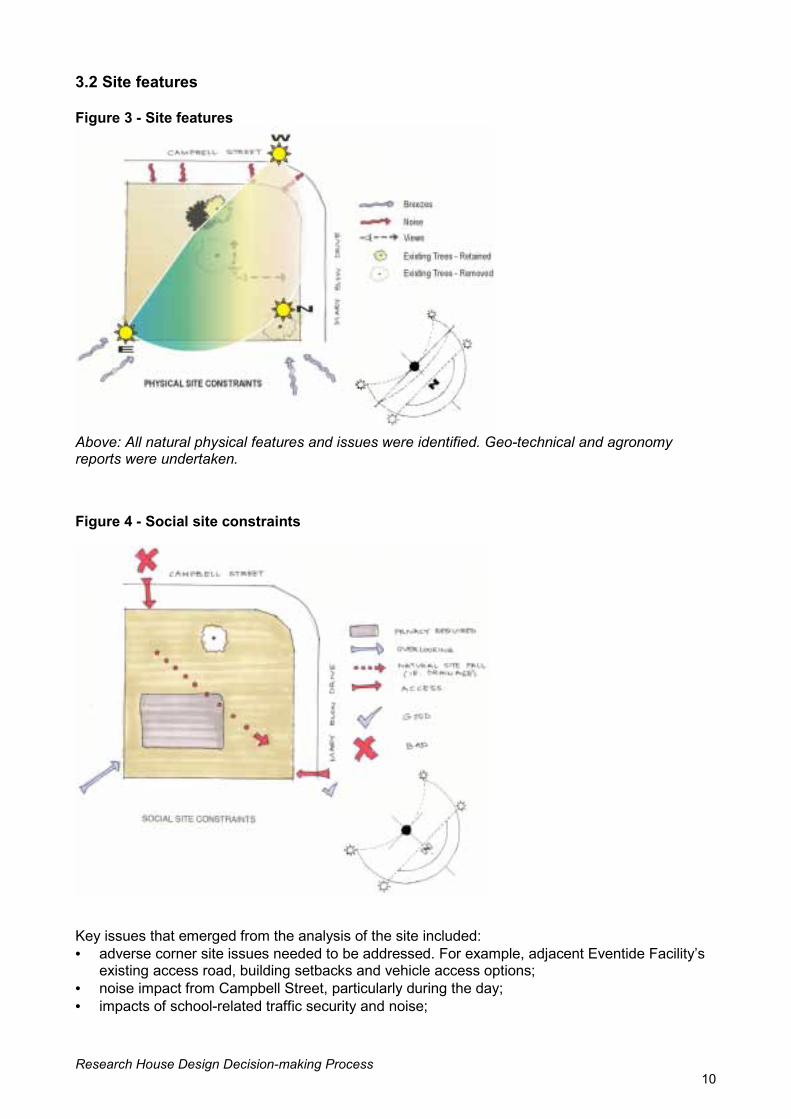
3.2 Site features Figure 3 - Site features
Above: All natural physical features and issues were identified. Geo-technical and agronomy reports were undertaken. Figure 4 - Social site constraints
Key issues that emerged from the analysis of the site included: • adverse corner site issues needed to be addressed. For example, adjacent Eventide Facility�s
existing access road, building setbacks and vehicle access options; • noise impact from Campbell Street, particularly during the day; • impacts of school-related traffic security and noise;

Research House Design Decision-making Process 11
• heat load and shading walls and windows due to the site�s north-west and south-west
positioning; • prevailing cooling breezes are from the north, south and east (rear) of the block; • ability to overlook the site from the adjacent Eventide Facility; • very little site cross fall meant there were few site level restrictions on planning options; • existing trees could be used for shading and height definition; • water supply is available in Campbell Street; • electricity is available in Campbell Street; • reticulated gas is available in Campbell Street; • Australia Post services are available in Campbell Street; • the old fuel shed is a possible site of contamination; • the street light pole requires relocation to make way for the construction of Mary Blow Drive;
and • the avenue of mango trees offered some shading potential and other trees to be retained. 3.3 Council requirements Figure 5 - Council requirements
Rockhampton City Council has developed a Smart City Plan which includes the following themes: • Enhance the city�s role as the service centre for the region. • Create a green city by protecting and enhancing Rockhampton�s unique natural assets and
through a program of boulevard and street planting. • Promote a city that is equitable and accessible by better accommodating cycling and walking. • Ensure development enhances personal safety. • Promote certainty and incentives for industry and business that encourages economical
development and employment initiatives. • Protect places of ecological and cultural importance for future generations. (Issues report � Rockhampton City Plan April 2000) Where possible, the project team worked closely with the town planning group in Rockhampton City Council to support and promote the ideals of the Smart City Plan within the design and construction of Research House.

Research House Design Decision-making Process 12
Key issues to emerge from the analysis of the council and regulatory requirements were: • Campbell Street is as busy sub-arterial road with substantial vehicle traffic; • vehicle access to and from Campbell Street is prohibited; • additional building setback requirements for corner blocks reduce the usable building site area
and may limit development. Council would need to give relaxation to street boundary clearances if required;
• rubbish bin collection services were available in the area; • a street light pole required relocation to make way for the construction of Mary Blow Drive; and • information from a 100-year flood plan indicates that the site is not prone to flooding. 3.4 Character Existing housing on Campbell Street varies in age, architectural style and construction. The Eventide Aged Care Facility on the adjacent site is the dominant feature on the street and was the closest building to Research House site. For this reason, it was decided that the Research House design should clearly respond to Eventide in its form and scale, specifically in terms of the roof form and masonry construction. More subtle reference to the existing housing in the street could possibly be achieved through the use of some materials and building elements such as: • corrugated steel roofing; • roof pitch; • wide overhangs; • external timber elements; • gable vents; and • landscaping.
Figure 7 - Recent development at the adjacent Eventide aged care facility
Figure 6 - Existing house on opposite side of Campbell Street

Research House Design Decision-making Process 13
4. KEY DESIGN ISSUES Before any design work was carried out, critical items were identified which were likely to impact on the design outcome. These were additional to the site analysis information and included key construction issues identified in the project design brief (see Appendix H). 4.1 Site drainage and water issues The following issues were identified: • Protection of the Fitzroy Basin and existing water catchment areas as specified in the
Rockhampton Smart City Plan. • A water pressure test was carried out on the existing water main to ascertain whether it was
suitable for Research House and the proposed sub-division. Accordingly, the water main was upgraded to ensure sufficient pressure for the future.
• Storm water collection � options considered were an in-ground tank under the garage (discounted as the sub-soil was unsuitable) and above-ground tanks (this was incorporated in the project).
• Black/grey water options were considered for irrigation or toilet flushing. However, Rockhampton City Council was not supportive of this option as it was inconsistent with their town planning provisions and the cost impact was significant. Neither option was incorporated.
• The impact that site drainage would have on future adjacent development was considered. 4.2 Display home issues The brief required that the house be open for public display immediately upon completion and undertake a pilot project period with occupants for a minimum of one year afterwards.2 Additional requirements such as substantial public access and public car parking facilities with universal access were necessary due to the public display period. However, these aspects should not compromise the design considerations for a liveable, four-bedroom family home. By developing the house as a regular home and not a display, it should reinforce the notion that Research House should appear as the first house in a proposed future sub-division to be accessed via Mary Blow Drive. 4.3 Key brief requirements Key design requirements of the brief included: • incorporation of the Smart Housing elements of social, economic and environmental
sustainability, specifically the: − adoption of energy conservation measures; − incorporation of passive design; − adoption of water conservation measures; − inclusion of universal design principles; − inclusion of crime prevention through environmental design (CPTED) principles; − minimisation of opportunities for injuries; − minimisation of long-term maintenance requirements; − adoption of resource management strategies; and
• minimisation of volatile organic compounds. • facilitation of research in sustainable housing design and construction; and • construction within a budget of $180,000.00.
2 Research House was open for public display from February 2002 to April 2002. Department of Housing tenants then moved into the house in October 2002 and will remain in the house until October 2004. Research has continued past the initial pilot period and is continuing at the time of publishing this document.

Research House Design Decision-making Process 14
The brief required broad public acceptance of the design and that the image presented by the completed house should be familiar to the public�s perception of attractive and affordable housing. This meant that a project home outcome was sought rather than a high-design architectural solution. Features considered consistent with a demonstration project home were: • simple roof shapes with short ridges and no skillion roofs to reflect the perceived image of what
a standard project home should look like; • concrete slab-on-ground floor system; • ceilings that are 2700mm high in habitable rooms; • aluminium windows; • specific room dimensions and furniture demonstrating useable spaces; and • practical, low maintenance and attractive landscape design. Additional requirements of the brief were: • roof pitch at a 25º angle to accommodate photovoltaic (solar) panels; and • the use of local tradespeople, products and suppliers where practicable, specifically the use of
flyash masonry block technology in construction to support Stanwell Corporation Ltd who had negotiated a local license for this technology.

Research House Design Decision-making Process 15
5. PRELIMINARY DESIGN 5.1 Site zoning Figure 8 - Site zoning external constraints
A series of exercises were conducted to identify general zoning arrangements in response to specific site constraints and to help identify conflicting zoning issues as described below in Table 2 � Site zoning opportunities and conflicts. Table 2 � Site zoning opportunities and conflicts Zone Ideal zoning response Conflicts Living areas and bedrooms
Orientation - In Rockhampton, it is appropriate to provide living areas with a northerly aspect. Most bedrooms will also benefit by facing north. Combined with wide overhangs, this allows the zones to be shaded in summer and allows the low-lying sun in winter to enter. The southern side of the house will only receive direct sun in early morning and late afternoon during summer.
Positioning the living areas and bedrooms to take maximum advantage of a northern orientation alone would result in the living areas being stretched diagonally across the site from east to west. This could limit provision of private outdoor space.
Breezes - Prevailing breezes range from the south-east to north-east. Arranging a narrow living area and bedroom wing approximately parallel and adjacent to Campbell Street would take maximum advantage of breezes.
Traffic noise off Campbell Street. The possible long corridor would restrict planning options.
Traffic - noise and privacy - Traffic noise and visibility off Campbell Street would suggest living areas and bedrooms are located away from this street.
Could expose private outdoor space to traffic noise and views to/from passing traffic.

Research House Design Decision-making Process 16
Garage Access - Safety considerations and
council preference require vehicle access to the site to be off Mary Blow Drive, adjacent to the north-eastern boundary.
The garage could be designed on the northern corner of the site and obstruct northerly aspect and some north-easterly breezes. Alternatively, the garage could be located in the eastern corner but would require a long driveway and reduce the area and quality of private outdoor space. A long driveway within the site would also pose safety concerns for children.
Orientation and breezes. - Locating the garage in the southern corner of the site would minimise undesirable obstruction of sun and breezes.
Requires unsafe access off Campbell Street.
Entry Access - Ideally, the entrance to the house would be closely related to both the garage and the living areas. Pedestrian entry off Mary Blow Drive is preferred due to the proposed location of the car parking for the display home being off Mary Blow Drive and the general preference to separate pedestrians and road traffic.
No significant conflicts.
Private outdoor space
Orientation -The covered outdoor area is ideally located with a northerly aspect, for maximum winter/summer sun exposure/protection, and provides the required roof overhang to the living areas.
Fewer opportunities for privacy and a conflict with the possible location of the garage.
Breezes - A location somewhere around the centre of the site with a narrow building to the west of the outdoor space would maximise desirable breezes across the outdoor space and through the house.
This places the house closer to the street, which is beneficial for access but undesirable in terms of traffic noise.
Traffic noise and privacy - Placing the private outdoor space in the centre of the site with the house shielding it from both streets would minimise traffic noise and maximise privacy to this space.
This places the house closer to the street, which is beneficial for access but undesirable in terms of traffic noise.
A summary of the major zoning conflicts revealed: • both the living and private outdoor areas are ideally located away from Campbell Street for
privacy and traffic noise issues; and • the ideal location for the garage in the northern corner restricts the preferred placement or
obstructs the northerly aspect to the living and/or outdoor living areas. A design decision was made to prioritise the safety considerations for the location of the garage, before the preferred orientation of the living area. Fortunately, the most practical location for the entry adjacent to the garage was ideal according to the intended zone analysis.

Research House Design Decision-making Process 17
Figure 9 - Site zoning response to external constraints
The final decision to be resolved was whether the indoor living or outdoor living zone would be positioned adjacent to Campbell Street. The decision to place the living area adjacent to Campbell Street was made for a number of reasons: • Planting could be provided along both street boundaries that would be high enough to reduce
traffic noise and provide privacy from the living area, yet low enough to allow casual surveillance of the street from within the house. Conversely, to provide this same degree of screening for an outdoor space adjacent to Campbell Street would require denser planting and reduce casual surveillance opportunities.
• Breezes through both the indoor and outdoor living areas could be achieved by placing the outdoor space to the east of the living space.
• The �L� shape of the building would help to create a more private outdoor living space, and allow indoor living spaces to spill into this zone.
• Some winter sun could still be captured by the indoor and outdoor living areas, especially in the morning, with tree planting adjacent to the street boundaries providing some protection from the westerly sun. The requirement for wide overhangs was noted at this point.
Figure 10 - Site zoning

Research House Design Decision-making Process 18
Figure 11 - Detailed site zoning showing kitchen relationship to indoor and outdoor living areas and wet areas grouped together

Research House Design Decision-making Process 19
6. DESIGN AND PLANNING 6.1 Space zoning The space zoning stage began with the final site zoning bubble diagram and considered the size and shape of the zones of the house, how they would relate to each other and what form the building would take. Style and functional requirements taken from the brief combined with the site character analysis and site zoning process indicated that the house should adopt an �L� shape with conventionally shaped internal spaces. As a further response to current trends and expectations in the marketplace, a decision was made at this stage to separate the main bedroom from the bedroom wing and place it nearer to the entry or living zone. Figure 12 - Space zoning
The space zoning layout was based on all of the site issues previously identified and the principles of passive design listed in the brief. The layout is as follows: • The L-shaped plan allowed the zoning of the house into living, sleeping, family and private
outdoor zones to maximize living opportunities. • The elongated L-shaped plan gives a long axis which has the benefit of making both arms of
the �L� only one or two rooms wide; this would greatly assist opportunities for cross-ventilation and cooling.
• Neighbourhood issues, e.g. the adjacent Eventide site and future sub-division were considered and influenced privacy planning and location of the zones on the site.
• Entry is off the secondary street frontage. A series of sketch plans followed on from the space zoning stage. At the sketch design stage, design issues were considered in more detail, individual rooms were sketched to scale, circulation space provided and provision made for the space required for structural walls and partitions.

Research House Design Decision-making Process 20
Early design considerations were: • entry from the secondary street frontage. The sketch designs sought to mitigate the less
obvious street address through the detail design of the entry. This issue illustrated the �classic� corner block scenario where a choice has to be made to face one street and turn at least the side of the house to the other street;
• the house was seen as a potential gateway to future development in Mary Blow Drive and the frontage should support this concept;
• the L-shaped plan should develop with equal consideration to the best orientation and privacy for occupants when outdoors;
• issues of placement of services, such as roof vents, should be considered and if necessary, eliminated from the street-side elevations; and
• although the �front� of the house addresses Mary Blow Drive, street appeal from Campbell Street is important and requires variation in form, material, colour and texture to provide an appropriate response.
6.2 Sketch plan 1 Figure 13 - Sketch plan 1
Positive attributes of sketch plan 1 • Basic zoning is good • The entry foyer is private, with entry porch visible from the street • The formal and family living spaces both access private outdoor spaces. Negative attributes of sketch plan 1 • Access from garage is through the formal living area • Form of the house and main entry do not address corner of site and Campbell Street • The floor plan does not allow effective cross-ventilation through the �elbow� of the plan • The main bedroom faces north-west, with adverse consequences for thermal comfort • Achieving cross ventilation and day lighting in the Campbell Street facing rooms and internal
hallway is difficult.

Research House Design Decision-making Process 21
Decisions for sketch plan 1 • Investigate building form being more responsive to corner of site and Campbell Street • Relocate main bedroom to gain better orientation • Investigate better cross-ventilation. 6.3 Sketch plan 2 Figure 14 - Sketch plan 2
Positive attributes of sketch plan 2 • House form responds better to corner of site and Campbell Street • The main bedroom is better located for sun and breezes. Negative attributes of sketch plan 2 • Formal and family living spaces are too strongly separated • Access from the garage is still through the formal living area • Achieving cross ventilation and day lighting of rooms facing Campbell Street and internal
hallway is difficult • Corner treatment is still not ideal. Decisions made for sketch plan 2 • Investigate moving main entry to corner • Make living areas more adjacent • Address corner of site more strongly.

Research House Design Decision-making Process 22
6.4 Sketch plan 3 Figure 15 - Sketch plan 3
Positive attributes of sketch plan 3 • Entry very clearly addresses corner • The living areas are more adjacent to each other • The laundry is screened and a courtyard has been added. Negative attributes of sketch plan 3 • The main entry is exposed to the western sun/wind and does not address the side street • The garage store is too far from rest of house • Cross ventilation and day lighting of rooms facing Campbell Street and internal hallway is
difficult. Decisions made for sketch plan 3 • Investigate kitchen being moved • Reinforce the �elbow� of the plan as a central space.

Research House Design Decision-making Process 23
6.5 Sketch plan 4 Figure 16 - Sketch plan 4
Positive attributes of sketch plan 4 • Necessary balance between privacy and openness promoting cross ventilation is achieved • The design addresses the corner and allows cross ventilation through a screened courtyard • The living areas are separate but can be combined as required • The entry addresses the side street • Building form addresses corner of site • The kitchen is still at the heart of the living area • The �elbow� of the plan is very open to allow cross ventilation and prevailing breezes but is
screened from adverse western sun by a screened courtyard • The garage store is more centrally located • An accessible path3 exists from garage to laundry courtyard as well as through all external
doors to the interior • Better exterior access to private outdoor space, which wraps around internal corner of floor
plan, thus having best orientation and exposure to prevailing breezes. Negative attributes of sketch plan 4 • Achieving cross ventilation and day lighting of the rooms facing Campbell Street and internal
hallway is difficult. Decisions made for sketch plan 4 • Cross ventilation above doorways (fanlights), ventilation/day lighting of hallway (skylights) and
wall partitions in living space not to full height.
3 An accessible path is defined as a clear path of travel from the street or car parking area, around and throughout the home that features level thresholds with a maximum of 10mm change in level, a minimum width of 1200mm, and any doors or openings providing at least 850mm clearance (minimum 870mm door leaf).

Research House Design Decision-making Process 24
The design development stage builds on the sketch design developed during the previous design stage. Issues of universal design, safety, security and passive design that helped to shape the sketch design are addressed in greater detail and strategies developed to assist the design decision-making to find a balance between these principles and the functions and appearance of the house. 7.1 Universal design strategy The seven principles of universal design developed by the Centre for Universal Design, North Carolina State University, guided decisions relating to access and mobility considerations in Research House. Additionally, the design strategy was checked against the Australian Access Standards Public Buildings (AS 4299): Part one (General requirements for access � new building work) and Part two (Enhanced and additional requirements � buildings and facilities). Of particular concern was the universal design principle of equitable use. This principle requires designs: • provide the same means of use for everyone; • provide privacy, security and safety equally for everyone; • avoid segregating or stigmatising people who use it; and • make the design appealing to people who use it. The design of the house achieved this principle by ensuring: • the path of travel from the kerb to the front door is shared by all visitors and presents no
barriers to people, regardless of their abilities; • the corridor widths and door widths allow people a with mobility impairment to visit all of the
living rooms and sleeping rooms; • the ensuite bathroom incorporates the access features required by the Australian Standards
but the design avoids stigmatising institutional aesthetics; and • the bathroom is accessible from the corridor without reducing the privacy of the master
bedroom.
7. DESIGN DEVELOPMENT STRATEGIES

Research House Design Decision-making Process 25
Figure 17 - Accessible paths of travel
7.2 Safety strategy Safety was considered throughout the house. Some design features within the house that address safety include: • fire safety
- an emergency evacuation plan, ratified by the local fire brigade detailing emergency exit paths from the house
- Crim-safe security screens fitted with the patented SAFE-E-SCAPE touch rail for ease of opening in an emergency, particularly for children
- in the kitchen, a fire blanket and extinguisher installed under the sink for unplanned events such as a fat fire on the stove;
• child proof cupboards for medicines and chemicals and child safe magnetic locks fitted to kitchen cupboards as an added safety feature;
• the kitchen is not a passageway; • the vertical corner where two walls meet in the high traffic hallway/family transition space has a
45° chamfer to reduce the risk of injury; • level thresholds help to prevent tripping; • the front path is separated from the driveway; • paints, carpets, furniture and other finishes throughout the house were carefully selected or
aired prior to occupancy to avoid contact with airborne chemicals; and • improved indoor air quality is achieved by specifying and selecting products and materials with
a low volatile organic compound content which eliminates chemicals such as, xylene, toluene and formaldehyde. Increased ventilation will also aid the dilution of contaminants in the indoor environment.
Research House Design Decision-making Process 26
7.3 Security strategy A crime prevention through environmental design (CPTED)4 strategy was incorporated to facilitate safety and security within the house. CPTED principles were applied to eliminate as far as possible the opportunity for the design to encourage crime, and also sought to encourage safety in all situations. CPTED principles used in the design of Research House include: • natural access control � provides a clear path of access to and from the house with the use of
pavements, fencing, lighting and landscaping to limit undesirable access; • target hardening � prevents easy unauthorised access; • natural surveillance � eyes on the street, encourages residents, through design features, to
naturally view the street from the house to limit criminal activity; • territorial reinforcement; and • image and maintenance. This strategy was incorporated into the design by: • eliminating corners in the house form and garden which might conceal persons; • providing natural access and surveillance to and from the house, by the careful analysis of
occupant sightlines and views to both the public and private domains; • landscaping which provides an appropriate display home image; • a high level of security to the house and private garden areas; • fitting dead locks to all external doors; • installing Crimsafe security screens to all openings; • positioning sensor lighting on the external perimeter of the house and connecting to the Clipsal
C-Bus system; • installing a panic button in the master bedroom which turns all internal and external lights on in
an emergency; and • fitting locks on yard fencing in areas of highest security risk.
4 CPTED ��is based on the premise that the proper design and effective use of the built environment can produce behavioural effects that will reduce the incidence and fear of crime thereby improving the quality of life� (Crowe, 1991).

Research House Design Decision-making Process 27
Figure 18 - CPTED strategy
7.4 Passive design strategy The environmental sustainability component of the triple bottom line approach to sustainability encompasses the principles of passive design. As air conditioning of the house was excluded in the brief, and one of the major aims of the project was to illustrate environmental sustainability, the use of appropriate and effective planning was imperative to achieve a successful outcome. To assist these aims, passive design was a key methodology used in the planning of the house. This is a proven and effective method to maximise comfort for occupants throughout the year. Passive design provides the best comfort conditions in a real life scenario, where all objective and subjective factors are considered. Passive design entails the use of an integrated set of passive design principles (i.e. integrated with the structure and siting of a building, not added to it as a solar water heater may be), which together lead to an effective use of the environmental factors affecting a site and maximise occupant thermal comfort. The principles cover: • sub-division planning; • the design process; • use of solar energy; • window and shading design; • heat storage; • insulation; • ventilation; • cooling; • day lighting; and • building envelope design.

Research House Design Decision-making Process 28
Research House passive design strategy incorporates relevant passive design principles through: • orientation of rooms, doors and windows, and placement of shade structures including roof
eaves to minimise solar exposure and heat gain; • assisting the cooling outcomes of passive design by drawing the prevailing breezes over
garden areas as they are watered, at a time when this would have the most beneficial effect, thereby pre-cooling the air before it entered the building. The town water used is supplemented by rainwater stored in tanks on the site;
• maximising ventilation through the use of the most effective and flexible window system, a mixture of sliding, louvered and transom windows;
• locating shaded areas where they block unwanted sun penetration and provide covered outdoor space;
• maximising available lighting through the use of solar selective skylights, while avoiding the unwanted effects of sunlight penetration; and5
• using natural day lighting as a major consideration in the design of the house. This included the use of solar tubes in the hallway and an innovative day lighting technology solar selective skylight in the living area. The innovative laser-cut technology provides a maximum amount of sunlight, particularly early morning and late afternoon low angled light, without the associated heat gains that are evident in other skylights.
Figure 19 - Passive design strategy
5 �Selective� sky lights are designed to only admit sunlight where it is beneficial, and are the result of research undertaken by Dr Ian Edmonds at Queensland University of Technology Brisbane.

Research House Design Decision-making Process 29
Figure 20 - Comparison between Research House and typical brick veneer construction (2000)
Typical house construction - Brick veneer walls (2000)
Research House - Single skin block work walls
Passive design ventilation strategy The passive design strategy incorporated a ventilation strategy. The ventilation strategy was integrated with the roof design, the L-shaped floor plan, thermal-flywheel6 cooling effect of the thermal mass of the largely-shaded walls, and the zoning of the plan into elongated parts. Use of the readily recognised hip roof form with gambrels in innovative ways, e.g. vented roof space, will produce a sustainable outcome with a form broadly acceptable to the public. Other key ventilation measures are: • high level ceilings (2.7m above floor level) to promote cross ventilation through the use of wall
openings and high/low level �elbow� of windows; • breeze pathways through the house were defined, especially at the bend in the L-shaped plan
where the main family living spaces are located; • assistance from active measures e.g. ceiling fans and adjustable elements; doors and windows
allow the substantial cooling effects to be modified seasonally and at different times during the day;
• pre-cooling of the prevailing breezes by irrigation of the gardens with town and rainwater, utilising the natural evaporative-cooling effect;
• the beneficial effects of positive and negative air pressure incorporated in building form and window size, type and placement;
• window systems that maximise operable areas; and • where the plan is two or more rooms, wide vented fanlights and skylights are introduced to
assist ventilation, cooling and natural lighting.
6 The �Thermal Flywheel� effect refers to the time-lag evident between part of a building mass which heats up until it radiates that heat. It can be used to reduce interior temperatures otherwise experienced by the insulation of the interior from the area heated, e.g. roof space, and the effective ventilation or cooling of the area heated until later in the day when ambient temperature drops. This can help avoid the worst effects of radiant heat.

Research H
The ventilation strategy avoids the popular response in project housing to minimise ventilation openings as they are more expensive than walling. This leads to a common situation in typical housing where: • thermal mass is relied on for resistance to ambient external conditions; • the minimum ventilation openings are incorporated which limits the house�s ability to be
effectively cooled; and • a reliance on retrofitted equipment (e.g. air conditioning). Figure 21 - Roof ventilation plan
Figure 22 �
ouse Design Decision-making Process 30
Roof and living space ventilation section
VentilationWarm air to escape roof space via louvres and soffit vents
Sliding glass doorsCross ventilation at high and low level

Research House Design Decision-making Process 31
Figure 23 - Typical section, room cross ventilation
Design development continues as the key design strategies are applied to the sketch design. Planning and design issues are resolved and integrated with a structural system and preliminary material selection while a balance is maintained between the requirements of the universal design, safety, security and passive design strategies. 7.5 Energy use strategy The house design seeks to minimise energy use and demonstrate this in a real life scenario. Key aspects of this energy strategy are: • maximising the renewable energy supply, achieved by the installation of a 1.9kW solar panel
system (photo-voltaic) linked to the Ergon grid system on a nett billing arrangement; • low energy lighting and ceiling fans; • a Clipsal C-Bus energy management system; • energy rated appliances were installed to reduce energy demand even further and a Quantum
heat pump was installed for water heating; • further research into water heating options will see a Solahart solar/electric boosted water
heating system installed, followed by a Bosch instantaneous gas system for evaluation; and • a �smart� energy management system. The house not only aims to reduce energy consumption by minimising the need for artificial cooling, heating and lighting, but attempts to address the question of, �what is an appropriate energy efficient water heater for a specific family living in the house?� The methodology used includes the installation and monitoring over three years for the energy and water use of what are generally considered to be energy efficient water heaters. This includes a heat pump, high efficiency gas and an electric boosted solar heating system, all of which will be tested for one year each. The strategy incorporates within the house a Clipsal Energy Management System which has a number of in-built design functions including time delay turn off switches, sensor and infra-red switches, an emergency lighting circuit, a security circuit and circuit control switching, all of which will reduce energy if used appropriately. Other energy minimising measures incorporated were: • solar selective skylights to maximise natural day lighting and minimise heat load in family areas
and solar tube skylights in the hallway and garage; • glazing systems which utilise low-E glass products and maximise natural cross ventilation.
These reduce unwanted heat energy transmission through glazing, particularly on western exposed windows, and assist in the elimination of the need for air conditioning;
• a drying court provides an undercover clothes drying area eliminating the need for a clothes dryer;
• sensor activated security lighting externally; • passive design; and • natural day lighting which reduces the daytime demand for energy.

Research House Design Decision-making Process 32
7.6 Water use strategy The general strategy used to reduce household water consumption was realised through smart water usage, and where appropriate, compliance with the Water Services Association of Australia (WSAA) - National Labelling Scheme to either �AAA� rating (less than 9 litres per minute); �AA� rating (9-12 litres per minute); or �A� rating (12-15 litres per minute). A water strategy is used throughout the house on the basis of the concepts of water fill and water flow. Water fill is where filling a bath or laundry tub in quick time is given a priority and flow restriction devices would not have been of benefit. The concept of water flow is more important in minimising the flow of water from a showerhead, hence the use of a �AAA� showerhead. Water saving devices used within the house include: • a battery-operated sensor tap at the vanity in the powder room which has a controlled flow rate
of 6 litres/minute and automatically shuts off water supply when the sensor isn�t activated; • some roof water is collected on site in rainwater tanks and re-used for irrigation; • storm water is generally discharged to the street channel as required by the local authority; • natural site drainage is encouraged, and is a key brief requirement in relation to sustainability
principles; • water usage and runoff is minimised through the use of plants suitable to site conditions; • dual, half and full flush toilet cisterns are fitted to toilets; • a water efficient dishwasher and clothes washer; • a zip water heater/cooler which provides hot and cold water at the kitchen sink; and • the garden sprinkler system is on a time clock and a moisture sensor to ensure that water is
only used when required. 7.7 Maintenance strategy Maintenance considerations were of primary importance. Preliminary research undertaken as part of the project revealed that in many cases, the selection of a building material and its treatment often ignores maintenance issues. This is unsatisfactory generally, but is particularly so when economic and environmental sustainability is considered. Consequently, all materials and their use were the subject of a maintenance analysis, which looked at life-cycle costing and the environmental impact of the choices made. Maintenance considerations in Research House included: • use of integrated CSR Renderline panelling which does not move or crack external wall
finishing; • use of external wall finishings which are self cleaning and ultra-violet resistant; • selection of carpet and tiles which are easy to look after and clean; • selection of Colorbond roofing, gutters and rainwater goods which do not require additional
painting and prevent corrosion; • inclusion of access points to the roof (safe access and egress); • inclusion of sliding doors (access for repairs); • use of Crim-Safe security screens manufactured from stainless steel mesh; • ready external access to plumbing services via lockable service doors; • development of a care and maintenance guide for residents; • the availability and lifetime of guarantees and warranties of products and materials; • quality of fittings and fixings; and • a whole-of-building termite management strategy.

Research House Design Decision-making Process 33
8. DESIGN DEVELOPMENT 8.1 Sleeping/services zone Figure 24 - Sleeping/services zone
The services zone (bathrooms and laundry) • The structural slab at the services zone is set-down. This allows installation of appropriate
floor falls without a change of floor level at the doorway. • The services zone was planned to be a regular shape so that the slab set-down was more
easily formed. • All components of the services zone are grouped together and the zone itself is located close
to the kitchen so that the water supply and drainage pipes have shorter runs. This is particularly important in reducing ongoing hot water costs.
• The ensuite is designed to be a fully accessible bathroom to enable a wider range of people to access it. This bathroom also opens to the hallway so that visitors needing the features of this bathroom do not have to go through the bedroom.
• The services zone is located to the west, freeing-up the north and east aspects of the house for the sleeping zone.
• Each of the bathrooms and the powder room has a window to provide ventilation and light. • The toilet is located close to the living zone so that visitors using the facility do not impose on
the privacy of the sleeping zone. • A basin is provided inside the powder room to allow users to wash their hands before touching
the door handle. • The provision of the powder room in addition to the bathroom allows both facilities to be used
concurrently.
Jane
Gre
aly

Research House Design Decision-making Process 34
The sleeping zone • Bedroom 2 is designed to double as a home office, and is located closest to the living zone. • The wardrobes are adjacently located between bedrooms two and three promoting aural
privacy. • The main bedroom is located remotely from the other bedrooms to promote aural privacy. • Three of the bedrooms have windows in more than one wall, thereby facilitating cross-
ventilation. • All bedrooms have ceiling fans and fanlights above doors for increased ventilation. • All bedrooms have a telephone connection which is also suitable for Internet access. Natural light • Extensive, well protected windows are located in all rooms, reducing the need for artificial
lighting during the day. • Skylights are located in the corridor to increase the natural light levels in the space. Ease of access • Structural plywood wall reinforcement (18mm) behind the wall lining is provided in the
bathroom walls to allow easy future installation of grab rails should it become necessary. The reinforcement allows the installation of an off-the-peg rail, rather than requiring careful measurement and installation of a rail manufactured to fit the position of the wall framing.
• The hallway is at least 1200mm wide to allow easy movement (including movement of furniture).
• Door handles are easy to operate. • Light switches and controls are positioned within the common reach zone (900 mm�1100 mm
above the floor). • Powerpoints are at the more reachable height of 600mm from the floor and 500mm out from
internal corners. • Sliding doors are selected as a better choice to standard doors because they are easier for
people with a mobility impairment to use and less likely to be the cause of injury for people with a sight impairment.
• There are no changes of floor level through the zone or at the doorways to the outside. • The overall layout of the plan is simple and logical, making navigation easier for everyone,
particularly people with cognitive and intellectual impairments.

Research House Design Decision-making Process 35
8.2 Living and ancillary zones Figure 25 - Living and ancillary zones
Jane Grealy The living and ancillary zones • The garage is positioned in the safest location, considering the traffic issues on the busier
street. • The foyer is located adjacent to the garage so that the entries from the street (pedestrian and
car) are grouped together. • The front door is clearly defined by its separate gabled roof and clearly indicates to visitors
where to enter. This is an example of the Crime Prevention through Environmental Design (CPTED) principle of natural access control.
• The majority of the house is visually private from visitors at the front door. • The foyer has direct access to the formal and informal living areas as well as the garage. • The more formal living areas are located towards the west as they are more likely to be used in
the evening when the western exposure is less problematic. • The semi-formal dining and formal living areas are partially separated from the other living
spaces. A three-quarter height wall was used to separate the lounge from the family space. This provides sufficient privacy while encouraging high-level ventilation throughout the living areas. The semi-formal dining area is only visually separated from the family areas and relates more to the lounge area than the family areas.

Research House Design Decision-making Process 36
• The less formal living areas are located to the east, affording a direct connection to the private outdoor area. The large doors can be opened so that the informal living space extends into the covered outdoor space.
• The verandah is a transition space between the informal living room and the backyard. A ceiling fan provides added air movement.
• A more formal covered outdoor patio space is located to the west and is accessible from the dining room. This space could be used by adults in the evening as a quiet refuge from the rest of the family. In the afternoon, the patio roof provides protection from the elements for the large sliding door to the dining room.
• The kitchen is strongly linked with the less formal living areas and incorporates a meals bench. • The kitchen, as the hub of the house, is critically located for convenience, service and
supervision of the internal and external spaces where children are likely to play. • The kitchen is not a through pathway, reducing the opportunity for collisions. Qualities of the living zone • The living areas are open, airy and well lit to increase comfort during the day and night time. • A combination of high ceilings, low internal walls (some containing timber louvres) and full
height windows with adjustable openings, provides good cross-ventilation for cooling. Higher ceilings also allow ceiling fans to be mounted at a safer height.
Qualities of the ancillary zone • The garage has a rear roller door which allows vehicle access to the back yard for
maintenance. This also allows the garage to be used as an extended, all-weather entertainment area if desired.
• There is access from the garage to the covered outdoor space via a large roller door, allowing the garage to be used as additional outdoor entertaining, hobby or living space, or as additional covered space in inclement weather.
• The garage and store area are adjacent to the foyer, providing secure and ready access to and from vehicles.
• The garage is conveniently located to the rear private areas. • The garage accommodates two vehicles and space for a work bench. • The store behind the garage can be used for storage of bicycles, mowers and other garden
and household tools. • The store is directly accessible from the garage and has a generous opening to the external
private areas. • Immediately adjacent to the store and garage is a covered paved area for multiple uses, such
as maintenance, handiwork or entertainment. • Roof space storage over the garage provides additional storage options and can be easily and
safely accessed by a pull-down ladder.

Research House Design Decision-making Process 37
8.3 Kitchen design The kitchen as a functional task area, can be expensive to modify and potentially hazardous zones. As such, universal design and safety considerations were paramount for this area. The design of the kitchen sought to produce an innovative and safe solution for people of varying abilities. The Department of Housing used it knowledge in kitchen design, gained through practical research and implementing the Capital Works program to develop this solution. The application of both the current disability access and the adaptable housing standards to Queensland�s public housing has developed a body of knowledge of practical measures. This knowledge and experience was applied in the design of Research House kitchen and other wet areas. These areas were then the subject of further design studies to produce a design that integrates the universal design principles with mainstream design in a way that does not appear to be different or unusual. Figure 26 - Kitchen layout
Servery
Kitchen FeaturesUniversal DesignFlexible Componentry to suit different uses
KITCHEN
Outlook
FRIG
180 Wheelchair Turn Kitchen Efficiency Triangle
Key considerations applied in the kitchen design were: • to achieve the greatest measure of accessibility for all users, e.g. minimal high-level
cupboards; • to enable a user with a range of abilities equal opportunity to fully use the kitchen; • the kitchen was to be at the centre of the floor plan as it is the �heart� of the house and this
would also enable easy surveillance of children�s play areas; • to maximise storage space and the functionality; and • that the kitchen not double as a passageway to minimise the opportunity for collisions.
Research House Design Decision-making Process 38
8.4 Storage Storage was also the subject of detailed attention. This study identified that while actual storage needs are rarely met in houses, much existing available space that can readily be adapted for storage is neglected. A more practical and cost-efficient solution was sought to maximise storage. It was decided to provide storage in the areas of the house where it would be most effective. Accordingly, there is storage capacity in the bathrooms, laundry, bedrooms and living areas. Other general and innovative storage provision was also investigated. For example, storage was provided in the roof space over the garage with the provision of simple sheet flooring laid over the roof truss bottom chords, and accessed from a pull-down ladder. An engineer designed and certified the roof framing to safely take a load of 900kg. The abundance of well-designed storage space throughout the house within the various rooms, garage and ceiling area provides for a clean, casual and uncluttered visual experience that allows the natural light to be easily reflected from the walls, floor and ceiling, and providing a perception of voluminous spaces. Less clutter around the house will also reduce hazards that could lead to injuries resulting from trips and falls. 8.5 Landscaping The landscaping seeks to resolve all external space considerations in an integrated way. The agronomy report identified vegetation to be retained and key aspects of site landscape which should be conserved. It was decided to complement existing vegetation in the local area. The conservation of existing vegetation on the site was an important aim of the project. A survey of the site identified vegetation and land form to enable these items to be planned into the outcome from the earliest opportunity. Retention of significant trees required a strategy of repair via tree surgery, stabilisation and the incorporation of a root barrier between the tree and the house to avoid physical root damage to the house and to maintain uniform moisture levels in the foundation soil.7 The need to provide the display house with effective landscaping and security also affected the type of treatment of outdoor spaces. Low planting was selected for the Campbell Street corner to maximise public views of the house. The application of crime prevention through environmental design (CPTED) principles to eliminate areas which might encourage criminal behaviour is also assisted through low planting in these public outdoor areas. To complement the display home function of the house, landscaping which is colourful but of moderate height to avoid visually dominating the house, was selected. Planting also needed to: • be tolerant of the existing clay soil; • be non-toxic and safe; • be a food source where appropriate; • provide visual amenity; • be hardy and have a relatively low requirement for watering; • be mature local plant species; and • support local bird life, e.g. nesting and food source for birds.
7 Unfortunately, at the time of construction, a mango tree on the western side was removed by a contractor without approval. This reduced some shading to that elevation.

Research House Design Decision-making Process 39
Options considered for plant selection were: • all native species, which have the advantage of having a very low need for water and fertilisers;
and • use of grass-type planting, however these type of plants were disregarded as there would have
been too little variation in type and would not produce flowers. Figure 27 - Root barrier treatments
Left: Landscaping sought to resolve all external space considerations in an integrated way. The choice of planting was made with the view to enhance the livability of the outdoor spaces and to be in harmony with CPTED principles. The public sides of the house were planted with hardy and colourful plants to suit the display house function in the short term and the semi-public realm in the long term. The private outdoor spaces were planted with not only shady, tropical and fragrant species, but also with fruit trees to provide edible fruits and vegetables for the occupants.
Root Barrier
Tree
House

Research House Design Decision-making Process 40
9. BUILDING ELEMENTS Building materials were considered throughout the project, especially those materials requiring particular construction techniques to be taken into design consideration, such as masonry walls, concrete slab-on-ground construction and materials that help determine the form of the roof and ceiling. The materials and construction systems used in Research House were, as a requirement of the brief, conventional to the building industry. However, the application of the materials and systems adopted best-practice design and construction principles, such as providing adequate ventilation and insulation to the roof space, and articulating the masonry wall construction. 9.1 Masonry forms and walls Recycled materials were used when constructing the house out of flyash masonry blocks. Flyash is the residual material from coal fired energy generation. Consideration was given to the use of recycled timber from a house to be demolished in Oxford Street, however no timber was suitable for use due to either water damage or lead paint. The design sought to balance the requirements to address: • adverse soil conditions (i.e. highly reactive clay soil) which required masonry walls to be
articulated; • a perceived need to have an interesting form with visual variation to Campbell Street, in
particular, variety of wall expression; and • the provision of removable panels to service plumbing for the wet areas. An effective R-value for walls was achieved through the selection of innovative flyash concrete blocks with foil backed plasterboard as the internal lining. This gave a predicted R-value for the wall system of 1.0. Benefits of the flyash block include: • the wall system compares well against brick veneer walls which were typical in 2000 and have
a R-Value = 0.46; • the flyash masonry was an effective source of mass to reduce noise transmission from the
busy traffic on Campbell Street; • articulation of the masonry into full-height panels of relatively short length was employed to
respond to the sub-soil conditions revealed by the geo-technical report; • a demonstration of recycled material in the manufacture of fly ash blocks; • the integration with CSR Renderline panelling over window heads and in the garage; and • the blocks are light in weight to reduce possible manual handling injuries. While conventional wall materials (brick veneer and standard concrete block) were considered, the use of flyash concrete blocks offered a breadth of opportunity which was seen to be valid and essential to the aims of the project. While the material is not yet fully commercially available, it has many benefits (e.g. the use of recycled material and a small environmental �footprint�) and has demonstrated that it would be accepted broadly across the construction industry. The balanced selection of masonry and lightweight construction for the external walls produced variety in external expression, reducing the visual mass of walls and presenting an opportunity to research the thermal effectiveness of different wall types and conditions. This latter issue is one aspect of the research now being conducted for the project.

Research H
Figure 28 - Articulation of masonry
9.2 Glazin The windowaims and toeffective cr Various cosliding glaslevel) wereconditions. Options co• clear gl• treated• mixed g �Smart� glareducing throoms. Thiwindows eand easterglazing so
ouse Design Decision-making Process 41
g
glazing strategy was intended to investigate smart glazing systems to meet the project use them effectively to reduce energy transfer to and from the building, and provide
oss- ventilation.
mbinations of types of glass and opening sash types were investigated. A mixture of s (at mid and low level), adjustable louvers (at low level) and in-line hoppers (at high chosen as this provided the most effective and controllable system for comfort
nsidered for glazing included: ass all round; glass all round; and lazing.
zing (low-emission glass) technology was chosen to maximise natural lighting by e transmission of unnecessary radiant heat while allowing light to enter the internal s selection was made to help achieve the brief requirement of a high rating under the nergy rating system (WERS). It was decided to install clear glass to northern, southern n walls while treating western walls with a combination of clear and three-star Optilight that performance comparisons could be made when exposed to direct sunlight.
Research House Design Decision-making Process 42
9.3 Slab-on-ground construction The use of slab-on-ground construction was a requirement of the brief, in part to demonstrate how easy access to the house (i.e. an accessible path of travel from �kerb to backyard�) could be achieved with the most typical floor system used in project housing. Stainless steel Termimesh was incorporated in the slab and formed part of the whole-of-building termite management strategy, which included timber treated with light organic solvent preservative (LOSP). 9.4 Roof and ceilings The brief requirement of an effective R-value was achieved through the choice of insulated light-weight roof construction with timber roof framing, steel sheet roofing, R1.5 thermal insulation blanket bonded to foil sarking (at underside of roofing) and R2.5 thermal insulation batts at ceiling level. Additionally, the brief required that no skillion roof forms be used to more closely reflect current industry practices. This, more than any other consideration, lead to the incorporation of the gabled entry roof and gambrel on the corner of a predominantly hipped roof form. Other design measures incorporated were: • the roof space between the roof and ceiling insulated planes was ventilated (approximately
2m2) to rid the roof space of built-up heat, by the use of vented eaves and gables; • alternative roof framing systems were investigated but the traditional timber-framed system
used provided the required performance with by far the least cost and was therefore adopted; • wide overhangs (900 mm) to provide effective shading and allow windows to be open when it is
raining, assisting effective ventilation; • ceilings which are 2700 mm high to allow the stratification of room air to move hot air near the
ceiling away from the occupied level; • the inclusion of energy-efficient fans throughout the living areas, bedrooms and external
outdoor area to enhance air circulation; • vented fanlight panels above internal doors to assist flow of breezes; and • slotted soffit sheeting for improved roof ventilation (approximately 0.46m2). The roof pitch was selected both for appearance and the opportunity to install solar panels and a solar water heater. While a heat pump mounted at ground level was used for water heating, a photo-voltaic array was installed on the roof to produce green energy. 9.5 Textures and colours Finishes The brief for Research House called for a selection of finishes that highlighted how easily sustainability strategies could be incorporated into residential finishes, which were familiar, easily identifiable and already available in the marketplace. For the exterior of the house, a neutral palette was selected in predominantly natural and light tones to complement the surrounding landscaping and urban environment.

Research House Design Decision-making Process 43
Internally, finishes were selected that allowed visitors to the house to be welcomed by a light and airy impression, which would be accepted by people with a variety of personal tastes. Texture and tone were also important considerations. Tiles were selected for the kitchen and meals area as the hottest part of the house and though the breezeway as they provided cooling by readily conducting heat into the slab and the ground. Soft woollen carpet was chosen in the relaxing zones such as the lounge room and bedrooms to engender a feeling of comfort. Carpet and tiles with a zero or low level of volatile organic compounds were selected to promote healthy flooring options. The contrasting textures of stone, natural timbers, natural fibres, low emission paint and careful colour selections created a home that was contemporary, stylish and pleasing to visitors from a diverse range of backgrounds, while being environmentally and socially responsive. Furnishings Furnishings were selected in a relaxed, contemporary style, with a mainly neutral theme with injections of vibrant colour as accents. The furnishings were chosen to reflect a stylish home that visitors could readily identify with. Care was taken to ensure that the internal colours and furniture were unobtrusive so that the sustainability features of the house could be showcased to the public. The local building industry was enthusiastic about the project and with their assistance, the project enjoyed the inclusion of mainly locally supplied finishes and furnishings, benefiting both industry and the supporting community. External colours External colours were selected both for their visual appearance and thermal performance. The benefits of the colour scheme selected included: • colours both externally and internally were kept in a light to medium tone to maximise natural
daylight; • light colours were used for the roof and walls to achieve solar reflectivity and reduce unwanted
internal heat build up; and • light/medium tones, rather than white or very bright light colours, were used to avoid adverse
glare for occupants and neighbours alike. Figure 29 - External colour selections
Paint waste Construction waste was minimised through the use of the Kruger Paint Wash System which provided for the separation of acryclic paint residue from paint waste, enabling waste water to be reused or disposed of in the drainage system and solid paint residue to be returned to the manufacturer or sent to land fill.

Research H
10. FINAL DESIGN
Figure 30 Floor plan of final design
Figure 31 A
ouse Design Decision-making Process 44
rtist�s impression of final design
Jane Grealey
Jane Grealey

Research House Design Decision-making Process 45
Figure 32 � Research House

Research H
APPENDIX A � SMART HOUSING Smart Houdesign andinitiative aim There are m• increas• lower e• being a• helping• more p A Smart Ho Social su Universall A universadifferent st Wide hallwbathroom/tfeatures of
ouse Design Decision-making Process 46
sing is simple, common sense housing design. It is good practice in the planning, construction of residential dwellings. The Department of Housing's Smart Housing
s to help Queenslanders to plan and build homes that are more sustainable over time.
any benefits of Smart Housing, including: ed liveability, comfort and peace of mind; xpenses and maintenance costs; ble to stay in your home longer, among friends and familiar neighbours; the environment; and eople interested in your house when it is time to sell.
use is more socially, environmentally and economically sustainable.
stainability
y designed
lly designed home is flexible and comfortable for people with varying abilities and at ages in their lives.
ays and doorways, level entries to the house and main living areas, and at least one oilet and one bedroom accessible for a person with restricted mobility, are some of the a universally designed home.

Research House Design Decision-making Process 47
Safe Safety is about preventing injuries in and around the home. Features such as reduced-slip flooring, a lockable cabinet for storing poisons and medicine, and ensuring that the kitchen is not also a passageway can improve safety in the home. Environmental health is also important. Careful selection of materials will affect indoor air quality. Secure Security is about using design and fixtures or fittings to reduce crime. The principles of Crime Prevention through Environmental Design (CPTED) can inform the design decision-making process. Environmental sustainability Smart Housing seeks to be more resource efficient in terms of waste, water and energy. Waste Careful design and planning can save materials being wasted during initial construction. It may also reduce the need for expensive modifications as needs change. Water You can achieve water efficiency by choosing water saving showers and taps and consider using rainwater water tanks for watering the garden and flushing the toilet. Energy Passive design features such as house orientation, ventilation, insulation and adequate shading can improve energy efficiency. In many cases, it is possible to keep inside the home cool in summer and warm in winter without resorting to artificial heating and cooling devices. Economically sustainable A smart house is cost-efficient. This means smart features are included in the initial design and construction, reducing the cost of changes and modifications in the future. A Smart House can achieve cost-efficiencies in many ways: Save on construction costs A Smart House can achieve cost savings at the initial design and construction stage through the use of cost-efficient building materials, economic planning and 'smart' ideas. Save on ongoing running costs Ongoing costs can really add up over the life of the home. Significant savings are to be gained by carefully considering the design of the home and which fixtures and fittings to include.

Research House Design Decision-making Process 48
Save on living costs Smart design features can save you money on a variety of everyday expenses such as cleaning, replacements and repairs as a result of accidents and breakages. Save on long-term maintenance costs Careful choice and selection of materials and the well-thought out design of a Smart House reduces both repair and ongoing maintenance costs. Save on future modification costs People's needs change over time. A couple becomes a family, an individual makes the move to work from home or an older person becomes less mobile. Each will require their home to work in different ways. Altering an existing home to accommodate changing needs can cost up to three times more than including the same features in the initial design and build stage. A Smart House has been universally designed, and will work for a range of people of different sizes, ages and abilities. Resale value Smart Housing features can lead to a greater demand for your home - the greater the demand, the higher the resale value. A Smart House will meet the needs of a greater range of people and therefore attract a larger market. With a massive increase in our ageing population and more people wanting to stay in their own home longer, a flexible and accessible home will become an increasingly valuable commodity. Peace of mind In a Smart House, the design and choice of fixtures and fittings have been carefully considered to ensure the safety and well-being of the occupants. This may reduce the risk of injury and therefore save on medical expenses, hospital bills and lost wages due to time off work. Cost efficiency for our community Cost-efficient housing also means savings for our community by reducing the effect of housing on the environment; reducing the likelihood of injury and the burden on the health care system; and reducing the incidence and cost of crime.

Research House Design Decision-making Process 49
APPENDIX B � SITE HISTORY
A brief history of a site at the corner of North and Campbell Streets The site is shown as a large reserve on the edge of the regular street pattern of Rockhampton in a survey of 1861. In 1878, the Colonial Architect, F.D.G. Stanley reported that a new gaol was under construction on this site, at the corner of Campbell and North Streets.
The gaol at this place was also commenced during the year, and is now well advanced; the whole will be completed during the present year. These buildings are constructed of concrete, brick, and stone, throughout, and will provide for the reception of fifty prisoners, with provision for extension. Contractor, Mr, J. Ferguson. Amount, £10,475.8
The project was extended to include Gaoler�s and Warders� Quarters in 1878. There were apparently delays in the construction of the buildings and other components needed to operate the gaol. In the following years, a number of contractors were engaged to undertake parts of the work, which were not completed until about 1883.9 In August 1942, the open area surrounding the gaol (and possibly the gaol) was taken over by United States armed forces.10 The site may have been used as a military camp. After the end of the Second War, work commenced on the construction of new buildings to provide a home for the aged and infirm. In 1946, the Colonial Architect�s Department�s annual report recorded: Work proceeded during the year on the construction of new buildings to provide a Home for the Aged and Infirm at Rockhampton. This project involves the demolition of the present Gaol Buildings. Provision is being made for the construction of additional Cells at the Police Station, to be used for Gaol purposes, and when these have been completed, further buildings can be erected on the site for the Home for Aged and Infirm.11 The project was completed in the year 1949/1950 and included cottages, hospital wards, administration buildings etc. The total cost of the project was over £130,000. In 1953, a new female ward was completed. This ward and the cottages were timber-framed buildings clad with asbestos cement. Similar homes were constructed at Sandgate, near Brisbane and at Charters Towers. Together with the mental hospitals at Brisbane, Toowoomba and Charters Towers, the Rockhampton Home for the Aged and Infirm formed part of a system of Government Homes and Hospitals in Queensland. No assessment of the cultural heritage significance of these places has been undertaken to date. From the information held in the Department of Public Works, it would seem that the site for the proposed new housing project is on open area adjacent to the former gaol. The lower parts of the site may contain fill. While it is possible that any fill contains spoil from the demolition of the gaol, this is now unlikely to contain useful information on the early use of this site and is unlikely to contain any archaeological evidence of this complex of buildings. The site is presently occupied by a number of cottages constructed circa 1950 and used to accommodate married couples at the Rockhampton Home for the Aged and Infirm.
8 Report on works carried out under the Colonial Architect�s Department during the year 1877. 9 Various annual reports of the Colonial Architect�s Department from 1877 until 1883. 10 Annotation on a block plan. See microfilm 371-1-4 HA/5/377 11 Report of the Department of Public Works for the year ended 30 June, 1946.

Research H
APPENDIX C � REFERENCES AND BIBLIOGRAPHY Aitken, R., Schapper, J., Ramsay, J., and Looker, M. (ed.) (1998) A Theoretical Framework for Designed Landscapes in Australia: National Overview Report, Melbourne: Burnley College, The University of Melbourne. Archer J., (1998) Your Home: the inside story of the Australian house, Thomas C. Lothian Pty Ltd, Victoria. Australian Construction Services (1983), Energy-Efficient Australian Housing, AGPS, Canberra. Australian Council of Building Design Professionals (BDP). (1995), BDP: Environment Design Guide, The Royal Australian Institute of Architects, Practice Services, Melbourne. Baggs, S and J. (1996), The Healthy House: the Gaian approach to creating a safe, healthy and environmentally friendly home, HarperCollins Publishers, Sydney. Ballinger, J. A., Prasad, D. and Rudder, D. K., (1997), Energy-Efficient Australian Housing, 2nd ed., AGPS, Canberra. Bell, N. (19Design GuGEN 21 Au Bentley I., Press, Lon Booth, N. Kfor the Priv Bowden, J. Brooker, NTechnologNovember. Brown R. DComfort an Building DeDesigners Bull, C. (20Contempor Bureau of MBureau of M Carmody, JTechnologi Carstens, DVan Nostra Colman J.,Australian
ouse Design Decision-making Process 50
98) �Waste Minimisation and Resource Recovery: Some New Strategies�, Environment ide. General Issues Note No. 21. Royal Australian Institute of Architects, Red Hill ACT, gust.
et al, (1985) Responsive Environments � A manual for designers, The Architectural don.
. and Hiss, J. E. (2002), 3rd ed. Residential Landscape Architecture - Design Process ate Residence, Prentice Hall.
, (1999) Living with the Environment in the Pine Rivers Shire, Pine Rivers Shire Council.
. (2001) �Greywater and Blackwater Treatment Strategies� Environment Design Guide. ies Note No. 11. Royal Australian Institute of Architects, Red Hill ACT, TEC 11
. and Gillespie T. J., (1995) Microclimatic Landscape Design � Creating Thermal d Energy Efficiency, John Wiley & Sons, USA.
signers Association of Victoria (1998), Designing In Waste Minimisation Building Association of Victoria, Doncaster East.
02) New Conversations with an Old Landscape � Landscape Architecture in ary Australia, Images Publishing, Australia.
eteorology, (1989), Climate of Australia, AGPS, Canberra. eteorology, (1992), Climate of Queensland, AGPS, Canberra.
., Selkowitz, S. and Heschong, L. (1996), Residential Windows � A Guide to New es and Energy Performance, W. W. Norton and Company, New York.
. (1985), Site Planning and Design for the Elderly: Issues, Guidelines and Alternatives, nd Reinhold, New York.
(1978) Streets for living � A Guide to Better Australian Residential Design Practice, Road Research Board.

Research House Design Decision-making Process 51
Commonwealth of Australia (1990), Ecologically Sustainable Development: A Commonwealth Discussion Paper, AGPS Press. Commonwealth of Australia (1992), National Strategy for Ecologically Sustainable Development, AGPS Press. Commonwealth Department of the Environment (1998), Waste Wise Construction Program Handbook: Techniques for Reducing Construction Waste. Commonwealth Department of the Environment, Canberra. Commonwealth Department of the Environment and Heritage (1995), 2nd ed., The Six Step Guide to Painting your Home � Lead Alert, Environment Australia, Canberra. Commonwealth Department of Health, Housing, Local Government and Community Services, (1993), Designing Subdivisions to Save and Manage Water, Occasional Paper Series 1, Paper 3 Better Cities Program, AGPS, Canberra. Commonwealth Department of Housing and Regional Development (1995), AMCORD A National Resource Document for Residential Development, AGPS, Canberra. Coombes, P. & Kuczera, G. (2001), �Strategic Use of Stormwater� Environment Design Guide. Design Strategies Note No. 44 Royal Australian Institute of Architects, Red Hill ACT, DES 44 November. Cooper Marcus, C., and Sarkissian, W. (1986), Housing as if People Mattered: Site Design Guidelines for Medium Density Family Housing, University of California Press, Berkeley and Los Angeles. Cooper Marcus, C., and Francis C., ed. (1998), People Places: Design Guidelines for Urban Open Space, Van Nostrand Reinhold, New York. Cooper Marcus C and Barnes. M., (1999) Healing Gardens Therapeutic Benefits and Design Recommendations, John Wiley & Sons, USA. Crowe, T. (1991), Crime Prevention Through Environmental Design: Applications of Architectural Design and Space Management Concepts, Butterworth Heinemann: Boston MA. Department of Housing (1999), Ask the 'Green' Question, Queensland Department of Housing, Brisbane. Department of Local Government and Planning (1997), Queensland Residential Design Guidelines, Queensland Department of Local Government and Planning. Department of Mines and Energy (1996), Energy Efficient House Designs for Queensland, Building Industry Group Marketing, Brisbane. (Out of Print). D'Alessio, V. (2002) Allergy Free Home A Practical Guide to Creating a Healthy Environment, New Holland, Sydney. Downton, P. F. and Fulton, C. (2001), �Urban Water Conservation, Harvesting and Reuse � South Australian Case Studies� Environment Design Guide. Case Studies Note No. 25 Royal Australian Institute of Architects, Red Hill ACT, CAS 25 November. Drysdale, J. W. (1975), Designing Houses for Australian Climates, EBS Bulletin No.6, 3rd ed., AGPS, Canberra.

Research House Design Decision-making Process 52
EBS (1973), House design for temperate climates, Notes on the Science of Building, NSB 21, Revised April, Commonwealth Experimental Building Station, Ryde, NSW. EBS (1974), House design for Australian cold-winter climates, Notes on the Science of Building, NSB 32, Revised January, Commonwealth Experimental Building Station, Ryde, NSW. EBS (1971), Thermal considerations in house design, Notes on the Science of Building, NSB 35, Revised October, Commonwealth Experimental Building Station, Ryde, NSW. EBS (1972), Natural ventilation of buildings, Notes on the Science of Building, NSB 43, Revised February, Commonwealth Experimental Building Station, Ryde, NSW. EBS (1971), House design for hot climates, Notes on the Science of Building, NSB 63, Revised October, Commonwealth Experimental Building Station, Ryde, NSW. EBS (1971), Cooling the home, Notes on the Science of Building, NSB 75, Revised November, Commonwealth Experimental Building Station, Ryde, NSW. EBS (1965), Insulating a house, Notes on the Science of Building, NSB 86, Revised August, Commonwealth Experimental Building Station, Ryde, NSW. EBS (1974), Physiological aspects of space heating, Notes on the Science of Building, NSB 95, Revised November, Commonwealth Experimental Building Station, Ryde, NSW. Energy Victoria (1994), Energy Efficient Housing Manual, Renewable Energy Authority (Energy Victoria), East Melbourne. Evans, M., (1980) Housing, Climate and Comfort, The Architectural Press Limited, London. Farrier, D. and Fisher, L. (1993), �Reconstituting Decision Making Process and Structures in Light of the Precautionary Principle�, paper presented at the Precautionary Principle Conference, Institute of Environmental Studies, University of New South Wales, 20-21 September 1993. Fisher R and Crozier B., (1994) The Queensland House � a roof over our heads, Queensland Museum Publication, Brisbane. Freeman, P. and Vulker, J. eds, (1992), The Australian Dwelling, Royal Australian Institute of Architects, Education Division, 2A Mugga Way, Red Hill, ACT 2603. Freestone R., (1989) Model Communities � The Garden City Movement in Australia, Thomas Nelson Australia, Melbourne. French, J. and Sullivan, B. (1994), Switch Home-based power, water and sewerage systems for the twenty-first century, Aird Books, Victoria, Australia. Geason, S. and Wilson, P., (1989), Designing Out Crime: Crime Prevention Through Environmental Design, Australian Institute of Criminology, Canberra. Gertsakis, J. (2001), �Water Conservation inside Buildings� The Environment Design Guide Products and Materials Note No. 25. Royal Australian Institute of Architects, Red Hill ACT, PRO 25 November. Gildemeister, H., (2002), Mediterranean Gardening: A Waterwise Approach, University of California Press, USA. Goldsmith, S. (1997), Designing for the Disabled: The New Paradigm, Architectural Press, Oxford.
Research House Design Decision-making Process 53
Gollings, J. and Michell, G., (1999), New Australia Style, Thames, UK. Goudie, D., (1993), Energy Efficient Housing in the Tropics, 20p Booklet, funded by Department of Primary Industries and Energy for Townsville Energy Action Group and North Queensland Conservation Council (Out of Print). Graham, P. (1996), �Waste Management: Source Reduction� The Environment Design Guide� Technologies Note No. 1. Royal Australian Institute of Architects, Red Hill ACT, TEC 1 June. Graham, P. and Smithers, G. (1996), �Construction waste minimisation for Australian residential development� Asia Pacific Journal of Building & Construction Management. Vol 2, No.1 p. 14-18. Graham, P. (1998), �Recycling Guide for the Victorian Building Industry� Resource Efficient Builder Program Vol.1 Issue 1, Master Builders Association of Australia � Victorian Chapter March, Melbourne. Gray, A. T., (1997), The Earth Garden Book of Alternative Energy, T. C. Lothian Pty Ltd, Victoria. Gray, A. T. and Hall, A., (1999) Forest � Friendly Building Timbers, Earth Garden Books, Trentham, Victoria. Greenland, J. and Szokolay, S. V. (1986), Passive Solar Design in Australia, RAIA, Canberra. Groad, P. (1999), Troppo - Architecture for the Top End, Pesaro Publishing Balmain NSW, Australia. Hannebaum, L. G. (2002), 5th ed. Landscape Design: A Practical Approach, Prentice Hall, Englewood Cliffs, New Jersey. Handreck K., (2001) Gardening Down - Under � A guide to healthier soils and plants, Landlinks Press, Collingwood, Victoria. Harris, C. (2001), Domain: Houses Inside and Out, (Sydney Morning Herald), Viking, Australia. Hartley, S., (ed) (1990), Make Your Home Safe and Secure The Working Weekend Series, J. B. Fairfax Press Pty Ltd, Sydney. Hayes, A. (1997), It's So Natural House Book: How to conserve energy and save money in and around your home, Angus and Robertson an imprint of Harper Collins Publishers Australia. Houghton, J. (1997) Global Warming: The Complete Briefing, Cambridge University Press, Cambridge. Hyatt, P. (2000), Local Heroes - Architects of Australia's Sunshine Coast, Craftsman House, Australia. Hyde, R.A. and Docherty, M, eds, (1998), Principles and Practices, 31st Australian and New Zealand Architectural Science Association Conference 1997, Pictorial Press in conjunction with Impress Media, Brisbane. Hyde, R. and Woods, P., (2000), Climate Responsive Design: A Study of Buildings in Moderate and Hot Humid Climates, E F & N Spon, London. Hollo, N. (1997), Warm House Cool House: Inspirational designs for low energy housing, Choice Books, Australia. Inner City Waste Board (1998), Draft Waste Minimisation & Management Manual for Construction and Demolition Waste. Sydney.

Research House Design Decision-making Process 54
Kay, M., Ballinger, J. A., Hora, U. and Harris, S. (1982), Energy Efficient Site Planning Handbook, Housing Commission of New South Wales, Sydney. King, S., Rudder, D., Prasad, D., and Ballinger, J. (1996), Site Planning in Australia, Strategies for energy efficient residential planning, AGPS Canberra. Katz P., et al, (1994) The New Urbanism: toward architecture of community, McGraw � Hill, Inc New York. Koenigsberger, O. H. et al (1974), Manual of Tropical Housing and Building: Part 1 Climatic Design, Longman, London. Kourdi J. (1999), Decision Making, The Orion Publishing Group Ltd, London. Lawson, B. (1996), �Recycling Building Materials� Environment Design Guide. Products/Materials Note No. 9. Royal Australian Institute of Architects, Red Hill ACT, PRO 9 August. Lawson, B. (1997), Building Materials Energy and the Environment: Towards Ecologically Sustainable Development, RAIA, Canberra. Lingard, H., Graham, P. & Smithers, G. (1998), �Waste Management � Civil and Civic Research Report�, Department of. Building and Construction Economics, Royal Melbourne Institute of Technology, Victoria, February. Lochhead, H. (1987), Gardens for Living - A Framework for Garden Design, Greenhouse Publications Pty Ltd, Richmond, Australia. �Mant Report�. (1994) Urban Design in Australia, Report by the Prime Minister�s Urban Design Task Force, Australian Government Publishing Service, Canberra. Marsh, W.M. (1983). Landscape Planning: Environmental Applications. John Wiley & Sons USA. Master Builders Association of the ACT (2001), Housing for Life, Master Builders Association, Lyneham, ACT, Paragon Printers, Canberra. ISBN 0 908222 16 5 McCauley, D. (1997), �Integrated Planning Bill: Second Reading Speech� 30/10/97 in Queensland Legislative Assembly, 1997, Official Record of the Debates of the Legislative Assembly (Hansard) Government Printer 3391. http://www.parliament.qld.gov.au/handocs/1997.pdf/971030ha.pdf (11/10/2002). McDonald, B. (1994), �Waste Minimisation and Recycling Program�, Fletcher Constructions Pty Ltd, Australia. McHarg, I. (1969), Designing with Nature Doubleday/Natural History Press. New York. Nelson, W. R. (1985), Planting Design - A Manual of Theory and Practice Stipes Publishing Company, Champaign, Illinois. Newman O., (1978), Defensible Space � Crime Prevention through Urban Design, Collier Books, New York. Newman, P., Kenworthy, J. and Robinson, L., (1992). Winning Back the Cities. Marrickville, NSW: Australian Consumers� Association. Oakley, D. J., (1961), Tropical Houses � A Guide to their Design, B. T. Batsford Ltd. London. Olgyay, V., (1967), Design with Climate � Bioclimatic Approach to Architectural Regionalism, Princeton University Press, Princeton, New Jersey.

Research House Design Decision-making Process 55
Oliver J., (1999) The Australian Home Beautiful � From Hills Hoist to High Rise, Pacific Publications Pty Ltd, NSW. Parnell, M., Cole, G. (1983), Australian Solar Houses, Second Back Row Publishers, Solar Scope. Paul, R. W. and Elder, L., (2002), Critical Thinking, Financial Times Prentice Hall, New Jersey, USA. Phillips, R. O. (1992), Sunshine and Shade in Australasia, CSIRO, Division of Building Construction and Engineering, Technical Report 92/2, CSIRO, Canberra. Pickett C., (1997) The Fibro Frontier: A Different History of Australian Architecture, Transworld Publishers (Australia) Pty Ltd, Moorebank. Power and Water Authority, Darwin, NT, Tropical Living: Design principles for energy efficient living, Darwin, NT. Queensland Health, West Moreton Public Health Unit, (1998) Child Home Safety Construction Guidelines, West Moreton Public Health Unit (Goodna), Paradise Printers Pty Ltd, Gold Coast. Rudin, D. and Falk, N. (2000), Building the 21st Century Home: the sustainable urban neighbourhood, Architectural Press, Oxford, UK. Reddrop, A., Ryan C. and Walker-Morrison, A. (1996), �Housing Construction Waste: Report for the Commonwealth Department of Industry, Science & Tourism�. Commonwealth Department of Industry, Science and Tourism, Canberra. Robinette, G. O. (1972), Plants, People and Environmental Quality: A Study of Plants and their Environmental Functions, U.S. Department of the Interior, National Park Service, Washington, D.C. in collaboration with the American Society of Landscape Architects Foundation. Robinette, G. O. (1977), Landscape Planning for Energy Conservation, Environmental Design Press, Reston, Virginia. Robinette, G. O. (1984), Water Conservation in Landscape Design and Management, Van Nostrand Reinhold Company Inc., New York. Saini, B.S. (1970), Architecture in Tropical Australia, Melbourne University Press, Melbourne. Saini, B. S. (1973), Building Environment - An Illustrated Analysis of Problems in Hot Dry Lands, Angus and Robertson (Publishers) Pty Ltd in association with the Royal Australian Institute of Architects, Sydney. Saini, B. S. (1980), Building in Hot Dry Climates, John Wiley and Sons, Sydney. Salomonsson, G. and MacSporran, C. (1994), �Recycling of Materials in Building and Construction�, CSIRO Division of Building, Construction & Engineering, Melbourne in Proceedings of the First International Conference on Buildings & the Environment, CIB TG 8, Building Research Establishment, UK. Samuels, R. and Prasad, D. (eds) (1994), Global Warming and the Built Environment, Chapman and Hall. Shanableh, A., and Chang W., (eds) (2001), Towards Sustainability in the Built Environment, Faculty of Built Environment and Engineering, Queensland University of Technology, Brisbane Australia.

Research House Design Decision-making Process 56
Shand, A. (1991), �Dream homes set to go the way of gas-guzzling cars�, The Australian, March 27, p. 26. Sim, J. C .R., and Seto, J. M. (1996) Inventory of Historic Cultural Landscapes in Queensland, Final Report Stage 1996, Brisbane Australian Garden History Society, Queensland Branch. Simonds, J. O. (1996), Earthscape � A Manual of Environmental Planning and Design, John Wiley & Sons USA. Simonds, J. O. (1997) 3rd ed., Landscape Architecture � A Manual of Site Planning and Design, McGraw Hill, USA. Skoyles, E. R. and Skoyles, J. R. (1985), �Waste Prevention on Site�, Mitchells Professional Library, U.K. Smithers, G. and Graham, P. (1995), �Construction Waste Minimisation for Australian Residential Development�, Report to the Australian Housing & Urban Research Institute. Spiro, T. (1996), Energy Conservation Manual, How to use energy more efficiently, TAFE Publications of Western Australia, Government of Western Australia. Stacpoole, J. M. (1992), What Timber Will I Use? Brown Prior Anderson, Burwood, Victoria. Standards Australia (1989), The Australian Standard AS3671, Acoustics - Road traffic noise intrusion - Building siting and construction, Standards Association of Australia. Standards Australia (1991), The Australian Standard AS1668.2, The use of mechanical ventilation and air-conditioning in buildings. Part 2: Mechanical ventilation for acceptable indoor-air quality, Standards Association of Australia. Standards Australia (2001), The Australian Standard AS1428.1, Part 1 Design for access and mobility � General requirements for access - New building work, Standards Association of Australia. Standards Australia, (1992), The Australian Standard AS1428.2, Part 2 Design for access and mobility � Enhanced and additional requirements � Buildings and facilities, Standards Association of Australia. Standards Australia (1992), The Australian Standard AS1428.3, Part 3 Design for access and mobility - Requirements for children and adolescent with physical disabilities, Standards Association of Australia. Standards Australia (1992), The Australian Standard AS1428.4, Part 4 Design for access and mobility � Tactile ground surface indicators for the orientation of people with vision impairment, Standards Association of Australia. Standards Australia (1994), The Australian Standard AS4226: Guidelines for safe house design, Standards Association of Australia. Standards Australia (1995), The Australian Standard AS4299: Adaptable housing, Standards Association of Australia. Steiner, F. (1999), The Living Landscape: An Ecological Approach to Landscape Planning, McGraw Hill, New York. Storey, M.S., Meuller, J., and Mace, R. (1998), The Universal Design File - Designing for People of Ages and Abilities, The Centre for Universal Design at the North Carolina State University.

Research House Design Decision-making Process 57
Sumner, R. (1974), Settlers and habitat in tropical Queensland, No. 6, Monograph Series, Geography Dept, James Cook University, 70p. Szokolay, S. V. (1982), Climatic Data and Its Use in Design, RAIA Education Division, Canberra. Szokolay, S. V. (1987), Thermal Design of Buildings, RAIA Education Division, Canberra. Szokolay, S. V. (1991), Climate, Comfort and Energy, Design of Houses for Queensland Climates, Architectural Science Unit, The University of Queensland. Szokolay, S. V., (ed) (1999), PLEA �99 Sustaining the Future Energy, Ecology, Architecture, Proceedings of the sixteenth international PLEA (Passive and Low Energy Architecture) conference Brisbane, Australia 22-24 September 1999. Volumes 1 & 2, PLEA International in conjunction with the Department of architecture, The University of Queensland, Brisbane. Szokolay, S. V. and Cowan, H.J., ed (1991), Heating and cooling of buildings, in Handbook of Architectural Technology, Van Nostrand Reinhold, New York. Szokolay, S. V. and Sale, R. W., (1979), The Australia and New Zealand Solar Home Book: A Practical Guide, Australia and New Zealand Book Co., Sydney. Tapper, N and Hurry, L., (1993), Australia�s Weather Patterns � An Introductory Guide, Dellastra Pty Ltd, Victoria. Thompson, G. F. and Steiner, F. R. (1998) Ecological Design and Planning, John Wiley and Sons New York. Thompson, W. and Sorvig K., (2000), Sustainable Landscape Construction: A Guide to Green Building Outdoors, Island Press, Washington, DC. Treib, M., (ed) (1993) Modern Landscape Architecture - A Critical Review MIT, USA. Turner T., (1996) City as Landscape � A Post � Postmodern View of Design and Planning, E & FN Spon, London. United Nations Conference on Environment and Development (1993): Agenda 21: Programme of Action for Sustainable Development. (The �Rio Declaration�). UNCED, Geneva. http://www.unep.org/unep/rio.htm van Dok, W. (2001), �Minimising Water Use in the Landscape� The Environment Design Guide, Design Strategies Note No. 43 Royal Australian Institute of Architects, Red Hill ACT, DES 43 November. Wekerle, G. R., and Whitzman, C. (1995), Safe Cities: Guidelines for Planning, Design and Management, Van Nostrand Reinhold, New York. Wilkie, G. and Arden, S. (1989) (Reprint), Building your own home � A comprehensive guide for owner builders, Weldon Publishing, Willoughby, NSW, Australia. Wilkie, G. and Arden, S. (2001) (Revised and updated for GST), Building your own home - A comprehensive guide for owner builders, Lansdowne, Australia. Willrath H. (1997), Assigning Thermal Star Ratings to Queensland Houses, Queensland Department of Public Works and Housing. Willrath H. (2000), (Reprint), Energy Efficient Building Design Resource Book, Renewable Energy Centre, Brisbane Institute of TAFE. Wilson, S., (1997), Some Plants are Poisonous, Reed International Books Australia Pty Ltd.

Research H
Windust, A., (2003), Waterwise House and Garden � A Guide for Sustainable Living, Landlinks Press, Victoria. Woodcock, S. & White, S. (2001), �Sustainable Urban Water Use � An Update� The Environment Design Guide General Issues Note No. 41 Royal Australian Institute of Architects, Red Hill ACT, GEN 41 November. Woolley, J. C. (1997), Abode of our dreaming: place, climate, culture and dwelling, USQ Press Toowoomba, Qld. Wolverton, B. C. (Bill) Dr, (1997), How to Grow Fresh Air: 50 Houseplants: that Purify your Home or Office, Penguin, USA. Wolverton, B. C. (Bill) Dr, (1998), Eco-friendly Houseplants: 50 Indoor Plants that Purify the Air in Houses and Offices, Books Britain. Wolverton, B. C. (Bill) Dr, and Wolverton, J. D., (2001), Growing Clean Water: Nature�s Solution to Water Pollution, Wolverton Environmental Services, Inc., USA. World Commission on Environment and Development (1987), Our Common Future. (The �Brundtland Report�) Oxford University Press. Yencken D and Wilkinson D., (2001), Resetting the Compass: Australia's Journey Towards Sustainabil
.
ouse Design Decision-making Process 58
ity, CSIRO, Collingwood, Victoria.

TERMS OF REFERENCE 1.0 The project
Background The Department of Housing proposes to construct a (4) Four Bedroom Slab on Ground Family House of Composite Construction to a five (5) star energy rating using the thermal performance computer model "BERS" (Building Energy Rating Scheme). The focus of the project is to demonstrate to the private sector by way of design and construction of a family home which reflects the values of the private sector market and aspects of design that the Department of Housing have implemented into its Housing Program in order to present the market opportunities that exist for builders and home owners alike at affordable cost. The project is proposed as an important housing research component as part of the �Smart Housing� concept. �Smart Housing� is a holistic approach to housing design and construction that recognizes and embraces the concepts of sustainability, affordability and climatic appropriateness in a responsible and responsive manner that reflects the changing lifestyle needs of the community. The title of the project is �Towards Healthy and Sustainable Housing� and will incorporate �ecological sustainable principles� �life cycle assessment processes� and minimizing �VOC's� (Volatile Organic Compounds) into all levels of the project. The key design considerations of the house will incorporate the concept of Smart Housing, which incorporates the general principles of:
• Universal Design; • Energy efficiency in terms of �passive solar design� and �energy smart building practices�; • Safe secure and healthy housing; and • Affordable housing in terms of cost effective over time.
Site constraints The identified site in the proposed Tranquillity Park subdivision is acknowledged as having a number of challenges. These challenges are listed for purposes of identifying opportunities in design terms and have obvious bearing on the internal room relationships, size and configuration of building. The challenges are:
Corner site issues: • Town planning set back requirements reducing site cover. • Three chord truncation of corner of street intersection. • Corner sites have a higher cost of development because of the aspects of �good manners
architecture� that is addressing both streets with positive design features of proportional window to wall ratio and length of building elevation.
• Street to property vehicle access restriction (Main Roads Department) from Campbell Street.
Climatic responses: • Aspect: Greater than 75% of Building Elevation faces North-West to South-West to Campbell Street; • Prevailing breezes: Morning: South-East direction; Afternoon: North-East direction. • Lot orientation: Long Axis addressing new subdivision street North-East.
Local Governments town planning requirements shall be complied with and should any issues arise that have impact on the project the Project Manager must liaise with the Project Director for direction. A submission of the proposed development shall be made to the Local Government at Sketch Plan and Developed Design stages in order to obtain a written �consideration in principle� statement from the relevant Local Government.
APPENDIX D � PROJECT DESIGN BRIEF

Research House Design Decision-making Process 60
2.0 Principles The key design considerations of the house will incorporate the concept of Smart Housing, which incorporates the general principles of:
• Universal Design; • Energy efficiency in terms of �passive solar design� and �energy smart building practices�; • Safe secure and healthy housing; and • Affordable housing in terms of cost effective over time.
2.1 Universal Design Universal design is a concept of �good common sense design� that is intended to optimize the usability of a designed product, environment and the like. Universal design does not attempt to assume responsibility for special individual groups. Its philosophical base is about holistic design for everyone (i.e. the largest possible class of people imaginable). Universal design principles are considered essential requirements in order to meet the changing proportion of housing needs. These needs are characterized by increasing demand for accommodation for people of all ages regardless of their level of ability or mobility. The following seven principles of universal design (Storey et al 1998) underpin the concept.
• Equitable use � the design is useful and marketable to people with diverse disabilities and avoids stigmatizing users;
• Flexibility in use � the design accommodates a wide range of individual preferences and abilities; • Simple and intuitive use � design is easy to understand, regardless of the user�s experience,
knowledge, language skills or current concentration level;
• Perceptible information � the design communicates necessary information effectively to the user, regardless of ambient conditions or the user�s sensory abilities;
• Tolerance for error � the design minimizes hazards and the adverse consequences of accidental or unintended actions;
• Low physical effort � design can be used efficiently and comfortably and with a minimum of fatigue;
• Size and space for approach and use � appropriate size and space are provided for approach, manipulation and use regardless of the user�s body size, posture or mobility.
Universal design features should include features such as wider hallways and doorways and level flooring with no thresholds. All can assist in reducing the potential for accidents for people with limiting mobility constraints. Universal Design need not look vastly different from regular housing design. It is the careful consideration of space, detailing, materials, and fittings, which guarantees its flexibility, safety and non-discrimination, not large identifiable design features. The challenge for designers is to let go preconceptions of modified bathrooms looking like hospitals and ramps standing out like sore thumbs. This �Universal Housing Design Concept� is advancement on the principles identified in the Australian Standards:
• AS 4299, Adaptable Housing, Class C; • AS1428.1, Part 1 Design for access and mobility - General Requirements for New Buildings'. The designer is encouraged to refer to the listed web site for further information on Universal Design. http://www.design.ncsu.edu/cud - the Center for Universal Design.

Research House Design Decision-making Process 61
2.2 Safety and security There are a number of important features to note within the concept of �safety and security� that are the preventative measures used to minimise injury and to provide a safe and secure home environment for all ages. In order to gain a greater understanding of the design issues for human safety around the home, the designer should consult the listed Australian Standard AS 4226 and Queensland Health�s �Child Home Safety Construction Guidelines� (copy attached). It is recognised that various competing design issues are interconnected when designing for all ages, so in order for clear communication the following are some essential requirements:
• Smoke Alarms: Hard-wired smoke alarms of a suitable type and "commercial quality standard" used in all public housing (refer to the Department's Schedule of Accepted Products).
• Home Security: At least front and rear security doors and one security screen per bedroom. All other windows to be provided with keyed alike window locks as a minimum.
• Personal Safety: Thermostatic mixing values.
2.3 Crime Prevention through Environmental Design (CPTED) Designers should incorporate the principles of Crime Prevention through Environmental Design (CPTED) where possible (refer to Crowe, 1991; Wekerle et al, 1995).
2.4 Crime Prevention through Environmental Design (CPTED) Concepts The basic concepts that a designer should embrace are to:
• Analyse, designate and clearly define the use of internal and external space for its functional requirements;
• Design the space to meet its designated defined use with the specific objectives to design a safe and secure environment that allows for natural surveillance and egress.
2.5 Crime Prevention through Environmental Design (CPTED) Strategies Some basic strategies that a designer should embrace are to:
• Provide clear border definition of space; • Provide clearly marked transitions from public to private space; • Place gathering areas in locations with natural surveillance and access control; • Place safe activities in safe places; • Provide barriers to conflicting activities; • Increase the perception of natural surveillance.
2.6 Energy Efficiency Principles It is recognised that there are many competing interests when incorporating these energy efficiency principles into a design, but the emphasis is to include as many of the principles of �smart design� and �passive solar design�12 that do not conflict with sound �urban design�13 principles of �good manners architecture�14. Incorporate these design principles into the design wherever possible: 12 A concept that harnesses the sun�s energy for controlling the lighting and heating of internal and external spaces, incorporating the beneficial aspects of
wind energy, particularly in residential building design and site planning.
13 Urban design is about the planning, design and organisation of the space between the private/public interface and the public space, that incorporates
societies economic, social and environmental systems that are reflected in the physical built environment.
14 This jargon term is a concept, which recognises the important responsibilities that a designer or a team of designers has to the neighbours and residents
of an area. The quality of the development is measured in terms of respect towards its neighbours and the way it has a positive contribution to the street.
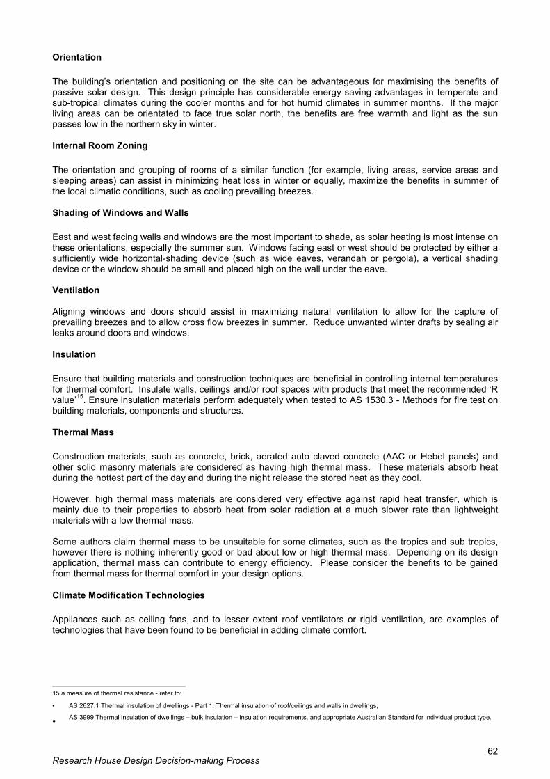
Research House Design Decision-making Process 62
Orientation The building�s orientation and positioning on the site can be advantageous for maximising the benefits of passive solar design. This design principle has considerable energy saving advantages in temperate and sub-tropical climates during the cooler months and for hot humid climates in summer months. If the major living areas can be orientated to face true solar north, the benefits are free warmth and light as the sun passes low in the northern sky in winter.
Internal Room Zoning The orientation and grouping of rooms of a similar function (for example, living areas, service areas and sleeping areas) can assist in minimizing heat loss in winter or equally, maximize the benefits in summer of the local climatic conditions, such as cooling prevailing breezes.
Shading of Windows and Walls East and west facing walls and windows are the most important to shade, as solar heating is most intense on these orientations, especially the summer sun. Windows facing east or west should be protected by either a sufficiently wide horizontal-shading device (such as wide eaves, verandah or pergola), a vertical shading device or the window should be small and placed high on the wall under the eave. Ventilation Aligning windows and doors should assist in maximizing natural ventilation to allow for the capture of prevailing breezes and to allow cross flow breezes in summer. Reduce unwanted winter drafts by sealing air leaks around doors and windows.
Insulation Ensure that building materials and construction techniques are beneficial in controlling internal temperatures for thermal comfort. Insulate walls, ceilings and/or roof spaces with products that meet the recommended �R value�15. Ensure insulation materials perform adequately when tested to AS 1530.3 - Methods for fire test on building materials, components and structures.
Thermal Mass Construction materials, such as concrete, brick, aerated auto claved concrete (AAC or Hebel panels) and other solid masonry materials are considered as having high thermal mass. These materials absorb heat during the hottest part of the day and during the night release the stored heat as they cool. However, high thermal mass materials are considered very effective against rapid heat transfer, which is mainly due to their properties to absorb heat from solar radiation at a much slower rate than lightweight materials with a low thermal mass. Some authors claim thermal mass to be unsuitable for some climates, such as the tropics and sub tropics, however there is nothing inherently good or bad about low or high thermal mass. Depending on its design application, thermal mass can contribute to energy efficiency. Please consider the benefits to be gained from thermal mass for thermal comfort in your design options.
Climate Modification Technologies Appliances such as ceiling fans, and to lesser extent roof ventilators or rigid ventilation, are examples of technologies that have been found to be beneficial in adding climate comfort.
15 a measure of thermal resistance - refer to:
• AS 2627.1 Thermal insulation of dwellings - Part 1: Thermal insulation of roof/ceilings and walls in dwellings,
• AS 3999 Thermal insulation of dwellings � bulk insulation � insulation requirements, and appropriate Australian Standard for individual product type.

Research House Design Decision-making Process 63
Energy Smart Appliances A number of essential considerations for Smart Housing and reduction of energy consumption would include the use of energy efficient lighting and other like appliances. Explore the safety aspect of incorporating gas appliances, such as a cooktop and oven into the design. Where the suitable site and climatic conditions prevail, consider the incorporation of one of the following low greenhouse gas emission hot water systems (Capacity 5 persons) into the design:
• Solar paneled Heat pump hot water system; • Solar (Gas-boosted storage type); • Natural gas (High efficiency storage type, 5 Star Rating); • Natural gas (Instantaneous type).
Natural Lighting (Daylighting) Efficient use of natural lighting is an essential consideration in any design. Seek opportunities for utilising natural light and/or sustainable lighting technologies at all stages of the design process.
Landscape Design A carefully considered design of the external environment can be extremely beneficial in terms of thermal comfort. Appropriate selection and placement of trees and shrubs, trellises and pergolas to shade the walls and windows can greatly moderate the temperature inside the building. For example, the planting of semi-deciduous trees to the north can provide shade in summer and allow sunlight to enter through the windows in winter. The functional use of groundcovers, as a ground surface layer provides for a visually pleasing environment that effectively reduces ground surface temperatures and unnecessary reflective sunlight and heat. The appropriate shading of the car park area with trees and shrubs is absolutely essential for reducing the �albedo� effect and providing a more visually pleasing environment. Street tree planting is required to assist in the shading of the street footpath, in order to moderate reflective sunlight and heat. Street tree planting is to be coordinated with the relevant local government.
Climatic Zones It is recognized that a number of climatic zones exist in Queensland. For the purposes of communication and understanding of passive solar design principles, the following climatic zones are to provide a psychological and physiological reference to gain an understanding of the climate variations. The climatic zone Rockhampton can be characterised as: Rockhampton has a Dry Sub-tropic/Tropical Climate, with hot and humid summer days and warm sultry summer nights; and comfortable winter days and cool winter nights. Temperatures: Mean January 26o C; Mean July 16o C; Summer extremes range from 27o C - 32o C; Winter extremes range from 10o C - 5o C. Average annual sunshine percentage: Summer 59%; Winter 68%. Prevailing breezes: Morning: South-East direction; Afternoon: North-East direction. 3.0 Project Objectives The project objectives are to:
• Facilitate research in Ecologically Sustainable Development building design and construction; • Incorporate Passive solar design; • Adopt energy conservation measures; (embracing the �energy efficiency program� within the
Department of Mines and Energy); • Utilise recycled materials wherever possible; • Adopt water conservation measures; minimize water use (embracing the �water wise program� within
the Environmental Protection Agency); collection of rainwater and seek to utilize grey water.

Research House Design Decision-making Process 64
• Maximise ventilation potential, thereby providing greater thermal comfort for the occupant/s; • Adopt resource management strategies; conservation of natural materials for building purposes; • Minimise the use of Volatile Organic Compounds (VOC) emitting construction materials and
improving indoor air quality. 4.0 Project Goals The aims of the project are to promote:
• employment opportunities; • skills improvement through on-the-job training; • local industry and manufacturers; and • Local institutes of learning and research. • environmentally friendly construction techniques and building materials are applicable to the
domestic housing market; and • Demonstrate that and the cost-effectiveness of sustainable technologies. • Gather research data on energy consumption, water consumption, internal and external air
temperatures. • Monitor the degree of thermal comfort within the building.
It is planned that the project be used for a display of building technologies and products. It is planned to be open to the public for a minimum period of 12 weeks and that industry and product manufacturers be offered sponsorship opportunities to showcase their products. Stanwell Corporation is recognized for the major role it plays in the local area and energy generation and this is an ideal opportunity for it to participate. Some of the partnerships in the project have been or are being developed with the following organisations:
• Department of Mines and Energy • Central Queensland University • Environmental Protection Agency • Department of Natural Resources • SD, Premiers, Police, Rockhampton City Council, DETIR, DNR, QMBA, HIA, Stanwell, AGO.
This project has extremely tight timeframes as the Minister has expressed that he would like to see the house substantially completed by 30 November 2000. 5.0 Scope of Work
5.01 The Design Process Brief
The brief is for the design, documentation and co-ordination of the total project including Master Planning for the integration of the two stage development as well as internal planning of buildings, site planning, services, driveways and external works to:
• Schematic Design Stage (SD) (Hourly Rate Only); • Developed Design Stage (DD) (Hourly Rate Only); • Contract Documentation Stage (CD); • Contract Administration Stage (CN) (Hourly Rate Only); • Provision of cost estimates and cost management control.
The Project Manager is responsible for the engagement, briefing, co-ordination, quality control and payment of all consultants. The following design disciplines are identified as being essential to the success for this project:
• Architect • Landscape Architect/Urban Designer • Structural Engineer • Quantity Surveyor • Hydraulic Consultants • Civil Engineer

Research House Design Decision-making Process 65
• Geotechnical Consultant • Surveyor • Town Planner • Electrical Engineer / Consultant • Arboriculturalist • Horticulturist • Drafter • Superintendents Representative
6.0 Budget The total construction budget for Stage one of the project is $180,000. The budget is fixed. The construction budget does not include Consultants fees. 7.0 Program The Principal Consultant shall submit for approval with the Project Proposal a project schedule of target dates for the commencement and completion of all architectural and associated Consultants� work. The Project Manager shall include in the program a minimum of one meeting per week with the Project Control Group and to include relevant Consultants at selected stages of the projects development. Specific Program Stages to be met:
• Schematic Design Stage • Approval of Schematic Design Stage • Developed Design Stage • Submit Preliminary Design Development • Town Planning Consultation • Approval of Design Development • Contract Documentation Stage • Submit Preliminary Tender Documentation (98% complete) • Approval of Tender documents (100% complete) • Processing and Printing • Call Tenders (Offers); Allow 2 weeks delay.
8.0 Liaison This project will be delivered by cooperative liaison between the Project Control Group, Housing Portfolio, Project Services, Q-Build, the Local Government and other Consultants. Given the timetable associated with the project, there will be a requirement to attend meetings at short notice. The Project Director is Michael Ball Telephone (07) 3224 5205 Facsimile (07) 3224 5820 E-mail address [email protected] All general enquiries and correspondence should be directed to this officer. The Project Design Manager is Ron Apelt Telephone (07) 3227 6065 Facsimile (07) 3224 5820 E-mail address [email protected] All design enquiries should be directed to this officer.

Research House Design Decision-making Process 66
9.0 Reference Documents The reference documents for this project are outlined below and the Project Manager should refer to them as appropriate during the execution of this brief.
• Draft Residential Design Manual (April 2000, Issue 1). This document is a guide only and should not be used as the stated requirements for this project.
• Photographic Instruction Sheet • Vegetation Management Policy • Refuse and Recycling Policy (State-wide) • Landscape Architectural Documentation Guidelines • Fencing Policy and Interpretations; This document is a guide only and should not be used as
the stated requirements for this project. • Schedule of Accepted Products; This document is a guide only and should not be used as the
stated requirements for this project. • Contour Detail Survey Plan (Part of Project Scope of Works)
10.0 PROJECT REQUIREMENTS
10.1 General Requirements The project is to comply with: Building Code of Australia (BCA) and other legislation. Fire Safety: Requirements for fire safety are to be in accordance with the Building Code of Australia (BCA). Waste Collection: Adequate provision shall be made for storage and collection of refuse and recycling bins. The Local Government should be contacted during the building design stage to determine the necessary requirements. Storm water Control: The Project Manager is to give particular and early attention to managing overland storm water flow. Floor levels for each dwelling are to be set to eliminate the risk of storm water entry. Site grading is to maintain site falls and avoid the creation of low points in longitudinal or cross-section. A drawing demonstrating the principles of the storm water design is required at the Schematic Design Stage and Developed Design Stage. The storm water plan will show all floor levels, the level and grade of all paths and paving, the fall of all ground surfaces and the intended route of overland flow clearly identifying any grates or sumps. Services: Provision of electricity, gas, sewerage and water is to comply with the particular Service Authority�s requirements. The Project Manager shall obtain information regarding the possible and existing location of water supply, gas, and storm water and sewerage services relevant to the site from the various service authorities. Telecommunication services: Telecommunication services shall be underground. The telecommunication network carrier shall provide one single entry point to the site for a ten pair telephone cable. The Project Manager shall contact the telecommunications network carrier to ascertain the requirements for reticulation including provision of cable and conduit and wiring as may be required. The Project Manager shall contact the appropriate Electricity Supply Authority to ascertain special requirements for electrical installations. All electrical requirements are to be included in the tender documentation. The Project Manager is to liaise with appropriate Electricity Supply Authority for provision of supply to site and allow for all costs associated with this service (including construction cost) in the cost plan. This work shall be carried out under the contract by direct arrangement between the Contractor and Electricity Supply Authority. Permanent electricity supply may not be immediately available to the land. If a temporary supply is required for building construction, the Project Manager shall nominate in the tender documentation.

Research House Design Decision-making Process 67
Internet Access: Permanent cabling is required for a number of outlets for computer internet access in Bedrooms 2, 3, 4 and isolated area within close proximity to Family Room. Cable Television: Permanent cabling is required in the Family Room for a single outlet for Cable Television connection. Electrical Meter Box: The location of the electrical meter box is to be easily accessible for meter reading but must not be positioned on front elevations of buildings or beyond fences and gated areas. Photovoltaic Array: A Photovoltaic Array (allow for 9 square metres of roof area) will be located on the roof of the dwelling at 25o to maximize the north to north-east sunlight. This will integrated into the design as details are developed with Stanwell Corporation. Vehicular Access and Car parking: Vehicular access is to be directly from the street allowing for tandem car parking on site on the driveway. Image: The dwelling and residential environment should evoke an image of �Home�. The test of success will be the extent to which the house is judged as making a positive contribution to the neighboring community. Recreational Space: The space around the dwelling shall be suitable for the peaceful enjoyment of its occupants, taking into account the need for privacy and security, and the active and passive recreational requirements of both children and adults. This space shall provide full opportunity for people with a mobility disability and allow total access to the landscaped surrounds. The Consultant is to report on any areas of the building, which are not readily accessible to people with disabilities, giving reasons why such access is not available or required. The Project Manager is responsible in providing the Consultant with any documentation for people with disabilities. Landscape Design: Practical landscape design should be used to minimize visual and noise intrusions and also provide protection from climatic extremes. Consideration should be given to the planting of suitably located and appropriate trees and shrubs to enhance the residential environment. However, care must be taken to ensure adequate visual surveillance of private enclosed space by occupants. The landscape design must allow for a vegetable and herb planting area and some appropriate fruit trees. Security: Security planning principles should be attended to at the planning stage by incorporating in the design, an integrated set of security measures appropriate to the dwelling and its locality.
10.2 Specific Design Standards ROOM LIST
Room name Description Entry The zone or area immediately outside the front door; Foyer The zone or area immediately inside the front door; Living Room A separate living room suitable for the furniture as listed and with
appropriate clearances; Dining Room A separate dining room suitable for the furniture as listed and with
appropriate clearances; Living/Dining A combined living and dining room; Kitchen A kitchen which may open through to a dining room or Living/Dining room; Separate Laundry A separate laundry room; Bedroom One A bedroom suitable for one queen size bed and other furniture. Bedroom Two A bedroom suitable for one queen size bed or a single bed and other
furniture.

Research House Design Decision-making Process 68
Bedroom Three, Four A bedroom suitable for two single beds and other furniture; Bathroom A bathroom suitable to the dwelling type; Ensuite bathroom An Ensuite bathroom suitable for the dwelling type; Separate toilet A separate water closet room; Linen store A storage area suitable for linen; Broom closet A storage area suitable for brooms and cleaning equipment; Garden store A storage space for garden tools and lawn mower easily accessible from
outside the building.
FOYER
• Provide a light (this is a separate light only if this is a separate space). • Locate switch inside entry door. • Floor is to be tiled.
ENTRY/FRONT DOOR GENERAL
• The entry is not to compromise the private outdoor space. These are separate areas with separate uses and separate access (as a minimum, they must be screened from each other).
• Provide a light, switch located inside the dwelling within easy reach upon opening the door. • Front door and doorway must have a width and circulation suitable for a swing door providing a clear
opening dimension of 850mm. • Maximum threshold height is 10mm. • Provide security swing door and doorway and width and circulation suitable to provide a clear
opening dimension of 850mm. • The front door and security door are to swing from the same jamb. • There must be no unscreened glass (openable or fixed) adjacent to the latch. • The plan of the dwelling must allow surveillance of the path leading to the entry.
LIVING GENERAL
• Ensure that living spaces are located on the northern side of the dwelling. • A living space is often combined with the dining space (circulation spaces can thereby be reduced). • Living space minimum width is 3600mm. • Provide a clear circulation space of 2250mm diameter after furniture has been placed (refer AS
4299-1955, Clause 4.7.1). • Past furniture and through the space is to be a minimum width of 1000mm (refer 4299-1955, Clause
4.3.7). • Furniture placement must allow television to be viewed from seating. • Provide direct access to provide private outdoor space (physical and visual). • Where doors open from the living space, furniture is to be placed to allow doorway width and
circulation suitable to fit doors to provide an opening dimension of 850mm (refer AS 4299-1955, Clause 4.3.7 and by reference As 1428.1-1998, Clause 7.3).
• The space must be visually remote from the WC. • Limit the number of rooms that open from the living room (this increased furniture placement
options). • Position the television point appropriately for anticipated furniture layout and adjacent to a socket
outlet (SO). • Provide two double socket outlet (SOs). • The telephone point (if provided in this space) is to be adjacent to a SO. • Provide a light and switch. Provide an additional light and switch where area exceeds 12m2.
Standard Furniture Requirements (excluding seating) Coffee table (900mm x 600mm) Television (800mm x 400mm) Storage/cabinet (1800mm x 400mm)

Research House Design Decision-making Process 69
Seating Requirements Allow for one of the following and provide on furniture layout:
• Two sofas (1500mm x 900mm each) and two chairs (900mm x 900mm each) or • Three sofas (1500mm x 900mm each) or • Two sofas (2100mm x 900mm each)
DINING GENERAL
• Ensure wherever practicable that dining spaces are located on the northern side of the dwelling. • A dining space may be combined with the living space for four bedroom dwellings only (circulation
spaces can thereby be reduced). • When a separate dining space is provided then the minimum width of the room must be 3000mm. • Provide a clear circulation space of 2250mm diameter after furniture has been placed (refer AS
4299-1995, Clause 4.7.1). • Where doors open from the dining space, furniture is to be placed to allow doorway width and
circulation suitable to fit doors to provide an opening dimension of 850mm (refer AS 4299-1995, Clause 4.3.7 and by reference AS 1428.1-1998, Clause 7.3).
• Position the dining space close to the kitchen. • Position the dining space visually remote from the WC. • Limit the number of rooms that open form the dining space (to increase furniture placement options). • Provide a 900mm minimum clearance to walls and furniture all around dining table (table size
depends on number of bedrooms). • A path past furniture and through the space is to be minimum width of 1000mm (refer AS 4299-1995,
Clause 4.3.7). • Provide a double socket outlet (SO). • Telephone point (if provided in this room) is to be adjacent to a socket outlet (SO). • Provide a light and switch.
Furniture Requirements 1800mm x 900mm table (placed in the open and eight chairs) and 1200mm x 400mm sideboard.
BACKYARD (PRIVATE OPEN SPACE) GENERAL
• Each dwelling must have a semi-covered private open space (of useful size, dimensions, orientation and services) capable of being used year round.
• There should be no ambiguity between semi-public (front) and private (back) spaces. • The type of surface treatment in private open space must reflect the intended use of the area
(clothes drying, children�s play, outdoor living, rubbish bin storage, garden). • Private outdoor space must be located to maximise desirable effects of climatic conditions. • Provide direct access to private open space from the living room or dining room. • Provide a paved outdoor area for outdoor living (minimum area of 8sq.m, minimum dimension in one
direction: 2.4m). Access to this area is to be directly from a public room (living room or dining room), preferably through a sliding glass door.
• Provide a light over the paved outdoor area switched from inside the dwelling. • The minimum dimension of the backyard in one direction is 4.0m
KITCHEN
General • The kitchen is to be a separate defined space (not necessarily a separate room). • Design must promote visual privacy of the kitchen. • Position the kitchen adjacent to the dining space, preferably to the northern side of the dwelling. • Position kitchen visually remote from WC.
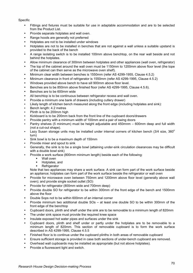
Research House Design Decision-making Process 70
Specific • Fittings and fixtures must be suitable for use in adaptable accommodation and are to be selected
from the Product List. • Provide separate hotplates and wall oven. • Range hoods are generally not preferred • Hotplates are not to be installed under windows • Hotplates are not to be installed in benches that are not against a wall unless a suitable upstand is
provided to the back of the bench • A range isolating switch is to be installed 100mm above benchtop, on the rear wall beside and not
behind the hotplates. • Allow minimum clearance of 300mm between hotplates and other appliances (wall oven, refrigerator) • The top of the cabinet around the wall oven must be 1150mm to 1200mm above floor level (the tope
of the cabinet can then serve as the microwave oven shelf). • Minimum clear width between benches is 1550mm (refer AS 4299-1955, Clause 4.5.2) • Minimum clearance in front of refrigerator is 1550mm (refer AS 4299-1995, Clause 4.5.2) • Windows provided above bench to have sill 900mm above floor level. • Benches are to be 850mm above finished floor (refer AS 4299-1995, Clause 4.5.6). • Benches are to be 600mm wide • All benchtop is to be continuous between refrigerator recess and wall oven. • Provide a minimum one bank of drawers (including cutlery drawer) • Likely length of kitchen bench measured along the front edge (including hotplates and sink): • Bench length: 4.2 metres • Plinth is to be 200mm high • Kickboard is to be 200mm back from the front line of the cupboard doors/drawers • Provide pantry with a minimum width of 100mm and a pair of swing doors • Pantry shelves (5 minimum) must be height adjustable and 450mnm � 600mm deep and full width
(not a cut-out shape). • Lazy Susan storage units may be installed under internal corners of kitchen bench (3/4 size, 360o
turn) • Sink bowl is to be a maximum depth of 150mm • Provide mixer and spout to sink • Generally, the sink is to be a single bowl (attaining under-sink circulation clearances may be difficult
with a double bowl sink) • Provide a work surface (800mm minimum length) beside each of the following:
! Wall oven ! Hotplates, and ! Refrigerator
Note that two appliances may share a work surface. A sink can form part of the work surface beside an appliance; hotplates can form part of the work surface beside the refrigerator or wall oven
• Provide for microwave oven between 750mm and 1200mm above floor level (generally above wall oven); and provide single socket outlet (SO)
• Provide for refrigerator (800mm wide and 700mm deep) • Provide double SO for refrigerator to be within 300mm of the front edge of the bench and 1500mm
above the floor • Double Sops not to be within 600mm of an internal corner • Provide minimum two additional double SOs � at least one double SO to be within 300mm of the
front edge of the benchtop • Cupboard doors, plinth and shelf under the sink are to be removable to a minimum length of 820mm • The under sink space must provide the required knee space • Insulate exposed hot water pipes and surfaces under the sink • Cupboard doors, plinth and shelf under or partly under the hotplates are to be removable to a
minimum length of 820mm. This section of removable cupboard is to form the work surface described in AS 4299-1995, Clause 4.5.5
• Finished floor is to continue under the cupboard plinths in both areas of removable cupboard • Ensure sufficient storage is provided in case both sections of under-bench cupboard are removed. • Overhead wall cupboards may be installed as appropriate (but not above hotplates). • Provide a fluorescent light and switch.

Research House Design Decision-making Process 71
HALLWAY GENERAL
• Minimum width of any hallway is 1200mm (structural dimension); ensure that walling is capable of enduring damage from the likes of wheelchair damage for at least 1000mm from the floor.
• Actual width informed by circulation space for doors that open from the hallway. • Provide a single socket outlet (SO) • Provide a light with two way switching • Storage spaces (linen, hot water unit & broom) and incorporated laundry (recess) may open directly
into a hallway • Where a surface mounted sliding door intrudes into the required circulation space at another
doorway, the width of the hallway must be increased to meet the requirements of AS 1428.1-1998, Clause 7.3
BEDROOMS GENERAL
• Ensure wherever practicable that bedrooms are not on the western side of the dwelling • Ensure wherever practicable that bedroom doors are aligned when located opposite each other. This
enables flow-through of breezes • A minimum of two windows per room is preferred. • Each bedroom is to have a light with a switch adjacent to the door • Each bedroom is to have two (SOs). • Separate the sleeping areas from the living areas • Generally position bedrooms close to bathroom facilities • Isolate sleeping areas from noise (coming from both within and outside the house) • Provide windows to two walls wherever possible (to promote cross-ventilation) • Protect windows in a way that allows ventilation during rain • Provide as many bedrooms as possible (minimum of two) with aspect (view to street, private open
space or similar)
Furniture Requirements Queen 530mm wide x 2030mm long Single 920mm wide x 1880mm long
Relevant furniture sizes Drawer unit 900mm wide x 600mm deep Desk 1200mm wide x 600mm deep
Built-in wardrobes • 600mm deep • Full width shelf 1700mm above finished floor • 16o hanging rail • One third of the length of the wardrobe (away from the corner is to be fitted with three additional shelves.
BEDROOM ONE • Room must accommodate a queen-sized bed with the head against a wall and access to the other three
edges • Double socket outlet (SO) is positioned adjacent to the bedhead • Provide one additional double SO • Minimum window sill height at bedhead is 1500mm • Provide telephone point adjacent to SO • Clearance to each side of the bed is 1200mm minimum • Clearance to the foot of the bed is 1540mm minimum

Research House Design Decision-making Process 72
• Provide built-in wardrobe with sliding doors � 2100mm long and preferably positioned away from the head of the bed
• Doorway must have width and circulation suitable to fit sliding door to provide an opening dimension of 850mm
• Dwelling units are to have ensuites accessible from bedroom one (also accessible from public areas) by sliding door with a width and circulation suitable to provide an opening dimension of 850mm
BEDROOM TWO • Room is to accommodate a single bed with the head against a wall • Double socket outlet (SO) is to be positioned adjacent to the bedhead • Provide one additional double SO • Clearance to each side of the bed is 1200mm minimum • Clearance to the foot of the bed is 1540mm minimum • Provide built-in wardrobe with sliding doors � 1800mm long and preferably positioned away from the
head of the bed • Doorway is to have a width and circulation suitable for door (sliding door preferred) providing an opening
dimension of 850mm
BEDROOM THREE AND FOUR • The room must accommodate two single beds positioned to provide access to a minimum of two edges
of each bed • Provide a drawer unit against the wall • Provide a desk against the wall • Two double socket outlets (SOs) are to be positioned with reference to furniture positions • Provide built-in wardrobe � 1800mm long to bedroom three only. In bedroom four, wardrobes are to be
1500mm long • Doorway is to have a width and circulation suitable for swing door providing an opening dimension of
850mm
BATHROOMS AND TOILETS
Ensuite bathroom 1
General The ensuite bathroom is the bathroom adjacent Bedroom 1.
• The ensuite is to be accessible from bedroom one and the public areas. • Both accesses are to comply with the requirements for circulation spaces at doorways. • Ensuite is to contain a shower recess area, toilet and a vanity. • Vanity to have clear accessible space under for cleaning purposes. • Shelving for clothes, towels and miscellaneous items whilst showering is encouraged. • Provide a light and switch near doorway. • Provide a double SO on wall beside vanity unit. • Provide exhaust fan and dedicated switch. • Locate bathrooms, wherever practicable, to the southern side of the dwelling, thus allowing living
spaces to face north. • Locate bathrooms to promote privacy from kitchen, living and dining spaces. • Fittings and fixtures are to be selected from the Product List. • Doorways are to comply with the requirements for circulation space. • Provide in wall sliding door with removal maintenance access panel to track.

Research House Design Decision-making Process 73
• Circulation spaces can overlap (refer As 4299-1995, Clause 4.4.1 and Appendix D and by reference AS 1428.1-1998, Clause 10.6 (a)).
• Use slip resistant tiled floor. • Splashback is to be tiled. • Waterproofing is to be in accordance with AS 3740-1994. • Towel rail/s (2) minimium number are to have minimum aggregate length of 1200mm (minimum
length of single rail � 600mm). • Provide two locations within wall framing suitable for attaching a future grabrail. • Double socket outlet (SO) on side wall at vanity bench is to be 600mm from the corner and 100mm
above bench height • Provide a light and switch • Provide exhaust fan switched with the light • Provide natural light and ventilation whenever possible. • Design of the bathrooms is to accentuate �domestic� and avoid �institutional� as much as is possible:
planning that minimised the floor area of the room is of particular relevance.
Shower ensuite bathroom 1 • Fit hobless 1200mm x 1200mm (minimum) shower area. • Shower configuration is to be as per AS 1428.1-1998, Figure 25 NOT Figure 26. • Position waste in centre of enclosed shower area. • Entire floor must fall to shower waste. • Position shower away from doors that lead to other rooms. • Reinforced wall areas. • Walls of shower area are to be tiled to the ceiling. • Shower curtain rail is to be located approximately 1800mm above finished floor level. • Soapholder is to be recessed. • AAA rated showerheads (release 9L per minute). • Shower mixer is to be approved for use in adaptable accommodation. • Ensure that the showerhead at the full extension of the hose does not reach to the rim of the WC.
This reduces the possibility of cross connection of the potable water supply. Ensuite bathroom 1 basin: fitted into a vanity
• Use semi recessed type approved for use in adaptable accommodation. • Height at front lip of basin is to be 770mm � 800mm. • Washbasin clearances are to be as per AS 4299-1995, Figure 4.4. • Waste is to be concealed in wall behind basin. • Circulation space. • Position the basin to the end of the vanity unit that is away from the corner.
Vanity
• Vanity must be minimum 1050mm long. • Vanity must be 300mm clear of the floor. • Drawers are to be minimum 450mm wide (with �D� handles) to one side. • Corners are to be rounded. • One 100mm high row of tiles is to be used as splashback to vanity. • Mirror behind vanity from the top of tiles to joinery height and minimum 750mm wide (900mm �
1200mm wide preferred).
Toilet in ensuite bathroom 1 • Provide ceramic bowl, plastic seat with lid, and cistern approved for use in adaptable
accommodation. • Set-out. Note that the set-out from the rear wall to the front of the WC is to be in the range of 800mm
to 820mm • Minimum dimension from centreline of WC to edge of shower area is to be 450mm.

Research House Design Decision-making Process 74
• Toilet roll holder. Bathroom 2: basin fitted into a vanity
• Ceramic basin is to be approved for general use • Basin mixer/taps and spout are to be approved for general use. • Waste (where exposed) must be chrome plated. • Position the basin centrally or to the end of the vanity unit that is away from the corner.
Vanity • Vanity must be a minimum 1200mm long. • Vanity must be 300mm clear of the floor. • Drawers are to be minimum 450mm wide (with �D� handles) to one side. • Corners are to be rounded. • One 100mm high row of tiles is to be used as splashback to vanity. • Mirror behind vanity from the top of tiles to joinery height and minimum 750mm wide (900mm �
1200mm wide preferred).
Bathtub with Shower Bathtub
• Tile the walls to the ceiling • AAA rated showerheads (release 9L per minute), bath spout and taps are to be approved for general
use (refer Product List). • Shower curtain rail is to be located approximately 1800mm above finished floor level. • Provide two soap holders.
Separate toilet • Separate toilet is to be located in a separate room with a swing door. • Provide ceramic bowl, plastic seat with lid, and cistern approved for general use. • Clear floor area is to be 900mm minimum width and 1650mm minimum length. • Toilet roll holder • Provide easy access to a hand-washing facility. • Toilet is to be located with access from public areas or laundry. • Provide a light and switch.
Laundry
General • Although, it is proposed to dedicated a room for the laundry. Smart, innovative design of internal
space is encouraged. • Locate laundries, wherever practicable, to the southern side of the dwelling, thus allowing living
spaces to face north. • There must be convenient access to a clothes drying facility.
Requirements • Doors to and from the laundry must have a width and circulation suitable for a swing door providing
an opening dimension of 850mm • Provide a 70 litre laundry tub (compact configuration preferred). • Provide space for appliances beside tub (1250mm long and 750mm deep). • Provide circulation space of 1550mm minimum clear in front of tub and appliances • Mixer approved fro use in adaptable accommodation is to be positioned on the sidewall at the
laundry tub. • 150mm swivel laundry arm is to be positioned on rear wall. • Connect dry floor waste (where installed) to frog flap (discharging above ground). • Floor is to be tiled (with tiles continuing under the wash tub). • Use one row of tiles as a skirting.

Research House Design Decision-making Process 75
• Provide tiled splashback to a minimum 450mm above tub and continuing as a band behind the appliances.
• Taps for washing machine are to be 1300mm above finished floor level. • Double Socket Outlet (SO) is to be located on the wall at rear of appliance recess, 1500mm above
finished floor level. • Fit wall mounted shelf unit above tub (two shelves � 600mm long and 300mm deep). • Provide light and switch.
STORAGE
General • Pantry (refer Kitchen) • Built-in wardrobes (refer Bedrooms) • Vanity (refer Bathroom) • Linen • Broom • Hot water unit • Poisons • Medicines • Exploit leftover spaces (eg. under or over stairs) to provide additional storage wherever suitable. • Storage areas (including wardrobes) may be provided under the eaves (with a consequently lower
ceiling height). Linen
• Fit top shelf at 1700mm and three additional shelves evenly spaced below. • Linen store may be provided as two separate stores: aggregate length must meet the minimums set
out below.
Four bedrooms • 1500mm wide (minimum) x 600mm deep (floor to ceiling)
Broom • 500mm wide x 450mm deep (floor to ceiling) with shelf at 1700mm
Linen/Broom • If the linen and broom storage are provided adjacent to each other, the two sections are to be
separate.
Poisons • One section of under-bench storage in the kitchen is to be fitted with a childproof latch.
Medicines • One section of storage in the bathroom is to be fitted with a childproof latch.
Hot Water Unit • Generally the unit is positioned to minimise draw-off losses: close or central to kitchen, bathroom
and laundry (with a preference towards the kitchen). • Generally the unit is preferred outside for ease of servicing and replacement (and so that the unit
can failsafe). • Capacity 5 persons.
Electrical requirements • Electrical installation including television, telephone and smoke alarm systems.

Research House Design Decision-making Process 76
Furniture list The following list established the minimum furniture to be shown in developed design drawings.
• Dining Table • Dining Chairs • Side Board • Sofas • Lounge Chairs • Coffee Table • Television • Storage/cabinet • Bed in First Bedroom • Bed in Second Bedroom • Beds in Each Subsequent Bedroom • Side Tables in First Bedroom • Drawer Unit in Each Subsequent Bedroom • Desk/Table in Each Subsequent Bedroom
CAR PARKING
General • Provide one enclosed and/or secure car accommodation space per dwelling (all garages and
carports for dwelling are to be fitted with garage doors). • Provide driveway (not car tracks) from the street • Clear internal minimum dimension of car accommodation is 6000mm x 3800mm with a minimum
ceiling height of 2500mm • Minimum door height is to be 2100mm • Car accommodation must not dominate in the streetscape • Car accommodation should be attached to the house • Provide covered access into the house • Provide one visitor�s car parking space on hardstanding per house (this may be in tandem with the
tenant�s car accommodation � on the driveway) Garages (enclosed)
• Provide a double weatherproof socket outlet (SO). • Provide an additional single SO located in a place that is suitable for future remote controlled door
motor. • Provide fluorescent light with two-way switch to inside the house. • Provide access to rear yard for the likes of a trailer.
CONSTRUCTION STANDARDS General
• The construction must conform to the building laws and local government requirements as applicable.
• All elements of the design should aim to minimise maintenance costs. • Materials must be used in accordance with the manufacturer�s written recommendations and
conform to relevant Australian Standards. Roofing
• Roof shapes are generally to be simple: avoid short ridges. • Avoid large skillion roofs that necessitate the extension of �walls� up to the raised top plate (these
walls would be unnecessary if a hipped roof form is chosen). • Roofing materials (concrete tiles or metal roof sheeting) are to be light coloured. • Roof pitch is to accommodate photovoltaic panels at 25o. • Use truss or conventional framing. • Framing of timber or steel must conform to the relevant codes.

Research House Design Decision-making Process 77
• Rainwater goods generally are to have a Colorbond finish. • Provide vents to roofs. • Seek opportunities for natural day lighting.
Eaves
• Provide vents to eaves and/or soffits. Ceiling
• Ceiling height generally is to be 2700mm minimum in habitable rooms. • Use recessed edge flush jointed sheeting on framing with painted finish. • Use textured finish to concrete slab soffit. • Provide an access opening to each ceiling space. • Provide eaves ventilation to ceiling spaces.
Walls External Use predominantly low maintenance material. Internal
• Apply painted cement render or painted recessed edge flush jointed sheeting to masonry. • Apply painted recessed edge flush jointed sheeting to timber or steel framing. Flush sheeting in
bathrooms is to be fibre cement. Door Thresholds
• Threshold at external doors is to be a maximum height of 10mm • Door seals must be provided.
Door sizes
• Doors are to have a 850mm minimum clear opening: • For complying swing door, minimum leaf size is 920mm • For complying sliding flush door, minimum leaf size is 1020mm • For complying aluminium framed glass door, provide door with overall frame width of 2100mm
(larger size is not preferred due to increased weight of door). • Provide wherever possible in wall sliding door with removal maintenance access panel to track.
External timber door
• Fit painted flush swing door with blockboard core. • Doors must swing inwards.
Internal timber door (swing and sliding)
• Fit painted flush hollow core door. • For sliding doors use in-wall sliding in.preference to surface mounting. • In wall sliding doors to have a removal maintenance access panel to track.
Door frames
• Doors are to have steel door frames.
Aluminium framed sliding glass doors
• Recess the bottom track of sliding glass doors. • Use a powder coat finish. • Use clear float glass.
Windows
• Fit aluminium framed glass windows. • Use a powder coat finish • Use obscure glass in bathrooms and toilets • Use clear float glass elsewhere. • Double hung winders are not acceptable. • Provide curtain brackets.

Research House Design Decision-making Process 78
• Ensure that window type is capable of meeting the requirements of Security Screening. • Ensure all windows are shaded. Horizontal extent of awnings or eaves should be at least half the
height of the windows • All glazing to comply with AS 2047.99 (WERS program).
Floors
• Floors are generally concrete slab on ground or suspended concrete slab. • Structural floors of ground floor bathrooms are to be set down 100mm to enable correct falls.
Termite Protection
• Provide termite barriers other than chemical spraying in accordance with AS 3660-1 and approved by the local government.
Steel Protective Treatment
• All steel work which is external or built into masonry shall be hot dipped galvanised after fabrication. Protection of Structural Timber Avoid designs and detailing in which structural timber is unnecessarily exposed to the elements. Unacceptable detailing includes:
• Exposed rafters and battens at eaves • Floor joists that continue out from under buildings to support decks.
Insulation Metal sheeted roofs Fit reflective foil laminate to AS/NZS 4200.1 with a flammability index not exceeding 5, installed in accordance with AS/NZA 4200.2 directly over rafters and under roof battens. Stretch foil laminate so as to hold the bulk insulation specified below in contact with the metal sheeting. Fit insulation material to AS 3742 installed in accordance with manufacturers instructions to achieve a minimum thermal resistance of 2.5m2K/W. External walls Provide insulation in all external walls to achieve a minimum thermal resistance of 1.5 m2K/W. For external brick/block veneer and lightweight cladding construction, provide reflective foil laminate to AS/NZS 4200.1 with a flammability index not exceeding 5, installed in accordance with AS/NZS 4200.2. Apply to the outer face of external stud walls from the top plate down over the bottom plate and flashing. Run across the studs and lap at least 150mm at joints.
SECURITY SCREENING Fly Screens
• Fly screens are to be provided with all security screens. Security Screen Doors
• Fit one to the front door • Fit one to a rear door • Key hooks are to be provided in an easily accessible location, out of sight from external view,
adjacent to the security screen door. Window Security Screens
• Fit one screen per bedroom (to the openable section of the larger window only � not across the fixed glass).
• All other openable windows are to be fitted with a keyed alike window lock.
Note • In instances where screening of the window compromises fire safety, provision for escape must be
established. The following are considered suitable:

Research House Design Decision-making Process 79
• Leave another easily accessible window (or windows) within the room unscreened. • Provide glass in the non-opening (fixed glass) section of the screened window that can be broken
and is in easy reach and large enough for an adult to exit through. • Fit an openable security screen to the window.
Window locks
• All unscreened openable windows are to be fitted with a keyed alike window lock.
FLOORCOVERINGS Wet Areas (kitchen, laundry, bathroom, toilet)
• Ceramic tiles are to be used. Note In special circumstances the floor covering in wet areas may be welded sheet vinyl (type and extent to be indicated in the brief). DOORWAYS (TO THE OUTSIDE) Swing front doors
• Ceramic tiles must be laid to an area of 1-2m2: actual extent will depend on design. Sliding doors from bedrooms
• Ceramic tiles are to be laid to the width of the door and the depth of the reveal. Bedrooms
• Concrete floors: Use direct-stick carpet. Public Rooms (living, dining, hallway)
• Concrete floors: Use direct-stick carpet or Non-Slip Ceramic tiles. 11.0 DESIGN MEETINGS
11.1 Design Team meetings Prior to commencement of any design work, a meeting of the �Design Team� comprising all Consultants will be called by the Project Manager to clarify all points relating to the Department�s expectations of Consultants� performance and to set in place, process for successful completion of this project. From time to time, the Project Manager may request additional �Design Team� meetings as required. All such meetings shall be chaired by the Project Design Manager, but it shall be the responsibility of the Project Manager to take minutes and arrange distribution. 12.0 THE DESIGN PROCESS
12.1 Schematic Design Stage (a) Site Planning Options The Options that are to be presented for approval are to address the following requirements:
• A thorough site description expressing the physical site conditions with particular reference to the levels, existing structures and vegetation.
• A Site Survey/Analysis (graphically and photographically). The site survey/analysis requires detail
consideration of the environmental, physical and legal aspects of the site. The three most important

Research House Design Decision-making Process 80
environmental aspects of the site are the microclimate (local breezes), access to sunlight and views from the site and into the site.
• Options for development expressing the positive and negative issues of each option. • The physical impact on the surrounding properties. The Project Director shall be advised
immediately if consultation with owners of adjoining property is needed, eg. building close to boundaries, existing trees, retaining walls and the like on the boundaries.
• The design should have taken the development to a stage where spatial and volumetric assessment
are practicable and clearly explained. • The preferred design option is to be justified under site planning issues and urban design principles.
(b) Building Concepts Building concepts that are to be presented for approval are to include the following:
• Plans to demonstrate that the requirements of the brief can be met and comply with the Local Government requirements.
• Notional elevations to demonstrate that principles embodied in the brief can be achieved eg. privacy,
address, etc. • Some of the more important aspects of the design to be shown are:
! Location of specific zones or spaces in the building with regard to their functional use,
maximizing views, inside/outside relationships (physical/visual) and utilization of solar access. ! Demonstrate the ventilation strategies for summer cooling. ! Location of windows and other openings should be established to assist in cross flow ventilation. ! The schematic design should be tested for its building envelopes thermal performance using a
computer simulation. (c) Site Development Concept Notional site drainage and all external works design are to be shown as preliminary but to the detail required in the Developed Design Stage. Schematic Design Cost Plan Note Refer to SCHEDULE OF DOCUMENTS for minimum submission requirements. Schematic Design stage is complete when signed off by the Project Manager.
12.2 Developed Design Stage
• The preparation of final design drawings including the following: • Demonstrated design details that address thermal design, such as shading devices, window design,
diagrams indicating shadow cut off angles so that the desired shade in provided in summer and sun penetration is achieved in winter.
• Site Development Plan (External Works Design). The site development plan should show pavement types, grassed areas, planted areas, spot levels and gradients, retaining walls and a preliminary drainage system sufficient to surface run-off.
• Elevations • Floor Plan/s • Developed Design Cost Plan
Note Refer to SCHEDULE OF DOCUMENTS for minimum submission requirements. Developed Design Stage is complete when signed off by the Project Manager.

Research House Design Decision-making Process 81
12.3 Design Review Requirements At Schematic Design Stage and Developed Design Stage the Project Design Manager in conjunction with the Project Control Group will appraise the design process with respect to:
• Compliance with the Residential Design Requirements stated herein. • Site Analysis. • The Design Brief (ie inclusive of all design requirements for the completion of the project). • Assessment of best option for suitability to site. • Architectural Quality (Building and Landscape Design) • Schedule of Finishes • Materials and durability - long term maintenance issues/analysis • Design Flexibility • Aesthetics • Cost Plan • The project shall not proceed to next stage unless endorsed by the Project Control Group.
Prior to presentation the Project Manager shall provide three (3) copies of A4/A3 bound report which shall include:
• Site Analysis • Constraints and Opportunities • Various options and rationale for their design. • Philosophical statement on preferred option. • Design solutions • Cost Plan
12.4 Selection of Materials and Products The Project Manager is to work through the Built Environment Research Unit, via the Project Design Manager for the �Selection of Materials and Products� to be used on the project. Although the Design Brief states specifically a number of materials, finishes and products, these are to be used for design purposes until Contract Documentation Stage. The Project Manager shall report on the preferred choice of construction and finishing materials with regard to the following consideration:
• local availability in both quality and quantity; • availability of skilled trades people to work with those materials; • suitability of application to the building type required by this brief; • frequency and type of maintenance required noting that finishes shall, as far as possible, be
maintenance free; • any requirement for testing on prototypes where materials or construction techniques may be
unusual; • weathering and ageing properties of materials used, ensuring by careful detailing that
weatherstaining of materials is kept to a minimum; • vulnerability to damage by vandalism; and • the performance of materials in extreme weather conditions.
12.5 Contract Documentation Stage
• This stage requires the approved design to be fully documented for the calling of tenders (offers). • Preparation of documents for tendering. • Briefing, instructing and coordinating all associated Sub Consultants. • Soil investigation report and Civil/Structural Engineering Certification. • The Project Manager will arrange for printing of tender documents and calling of tenders. • Pre-Tender Cost Plan. • Answer queries raised during the tender period and respond appropriately.

Research House Design Decision-making Process 82
• Assist the Project Director and Project Design Manager with analysis of the received tender and provide advice with respect to the cost or build ability issues relating to tender/s received as and when required.
• Formally award the Project through the administrative processes to the successful tenderer.
12.6 Contract Administration Stage
• This stage of the project is administered by the Project Manager and will require the following services to be undertaken:
• As required, inspection of the works in conjunction with the Project Design Manager and/or Project Director on a regular basis to ensure work in undertaken in accordance with the documents and that any problems with documentation are resolved.
• Adjust documents as and if required and issue amended drawings. If the changes are a result of consultant errors no payment will be made for this work.
• Checking of contractors claims and making recommendations to the Project Director/ Project Design Manager. Project Manager will issue certificates if contractors claims are validated and financially approved by the Project Director.
• Generally dealing with other matters arising from the administration of the building contract. 13.0 SCHEDULE OF DOCUMENTS The following schedule of documents represents a minimum requirement.
13.1 Schematic Design Submission
• The Project Manager/Consultant are to comply with the specific submission requirements as set out below.
• The Project Manager/Consultant is required to submit one (1) copy of simple sketch paper drawings
of the following information at schematic design stage, on the date agreed with the Project Design Manager. Free-hand to scale drawings are acceptable.
• Location plan showing the relationship of the site to adjacent building and landscape features within
a 500 m radius (Scale 1:1000 to 1:2500). • Site analysis drawings showing constraints and opportunities including access points and vegetation.
Simple site sections and photographs of neighboring projects with comments on form, materials, etc. are to be included. Show location of existing or proposed substation directly affecting the site.
• A written report on all existing vegetation found on site with statements on the rationale why the
vegetation should be retained or removed. A cost benefit analysis may be required by the Project Design Manager for justification of removal of vegetation. Provide a cost benefit analysis in liaison with the Departments Landscape Architect for costings (liquidated damages) of vegetation to be retained. (NOTE: Vegetation generally means trees, palms and shrubs)
• Alternative development strategies, setting out significantly different options and evaluating them
against the conclusions drawn from the site analysis and architectural analysis of similar and neighboring projects.
• A preferred design should be nominated with clearly stated reasons for selection. Reasons for
rejection of other schemes should be evident. • A schematic design site plan of the Project Manager/Consultant�s preferred design showing all
existing and altered landforms, pavement types, grassed and planting areas, and the location of main services (1:100). Set backs and plot ratio are to be clearly identified to facilitate client approval.
• Plan elevations and sections (where necessary) of the preferred unit plans sufficient to explain the
scheme and to an appropriate scale, preferably 1:100 or 1:50. A roof plan is to be included. (Note complex roof plan/s are not acceptable)

Research House Design Decision-making Process 83
• Drawings showing the primary hydraulic (ie stormwater design, major drainage routes, etc) and
landscape proposals. • A report in A4/A3 format, giving a brief description of materials and construction and including a
schedule of proposed areas of all spaces as per Residential Design Requirements. The report is to include reductions of all drawings.
• A copy of the Application Letter to the Local Government requesting Consideration-in-Principle for
the project. • Each drawing and the front page of the report is to be clearly titled: �Project Title, Schematic
Design�. • A Cost Plan for the preferred option. A cost summary of each option should also be provided.
13.2 Developed Design Submission
• The Project Manager/Consultant is required to submit three (3) copies of the following drawings and report at Developed Design Stage on a date agreed with the Project Design Manager.
• Location plan showing the relationship of the project site to existing buildings and landscape
features. • Site design development plan of the Consultant�s preferred design showing all existing and altered
landforms, pavement type, grassed and planting areas, and the location of main services (1:100) and with floor plans. (Note: Finished and existing ground lines must be shown). Setbacks and plot ratio are to be clearly identified to facilitate approval.
• Roof plan to 1:200 minimum, showing slopes, materials and penetrations. (Note: Complex roof
plan/s are not acceptable) • Elevations of all aspects to 1:100 scale, showing roof forms and all projections above the roof. • Elevations of the overall scheme or part of the scheme to a scale of 1:100. • Sections through the overall scheme or part of it to a scale of 1:100. • Provide separate External Works Plan/s, scale 1:100, refer to Landscape Architecture
Documentation Guidelines and show the locations of the following; • Telecommunications Network Carriers pits/pillars in relation to the site. • Site servicing drawings showing all hydraulic services ground levels, floor levels, location of sumps
and overland water flow, etc. • Landscape design plans and supporting drawings showing in detail the plant types (graphically) and
a suggested plant list, the extent and type of fencing, the pavement types, grassed and planting areas, retaining walls, external lighting and the like.
• Stormwater control plan
• Plans, elevations and sections of the proposed building types at 1:100 or 1:50, clearly showing
ceiling and roof heights, construction methods and indicating typical details. Indicative furniture layouts and room dimensions are to be shown on the plans. All floor areas calculated to outside face of external walls are to be shown.
• Sample boards on Hardboard or similar (Maximum Size A2) showing materials to be used for
external and internal finishes. The boards are to show clearly the locations in which materials and
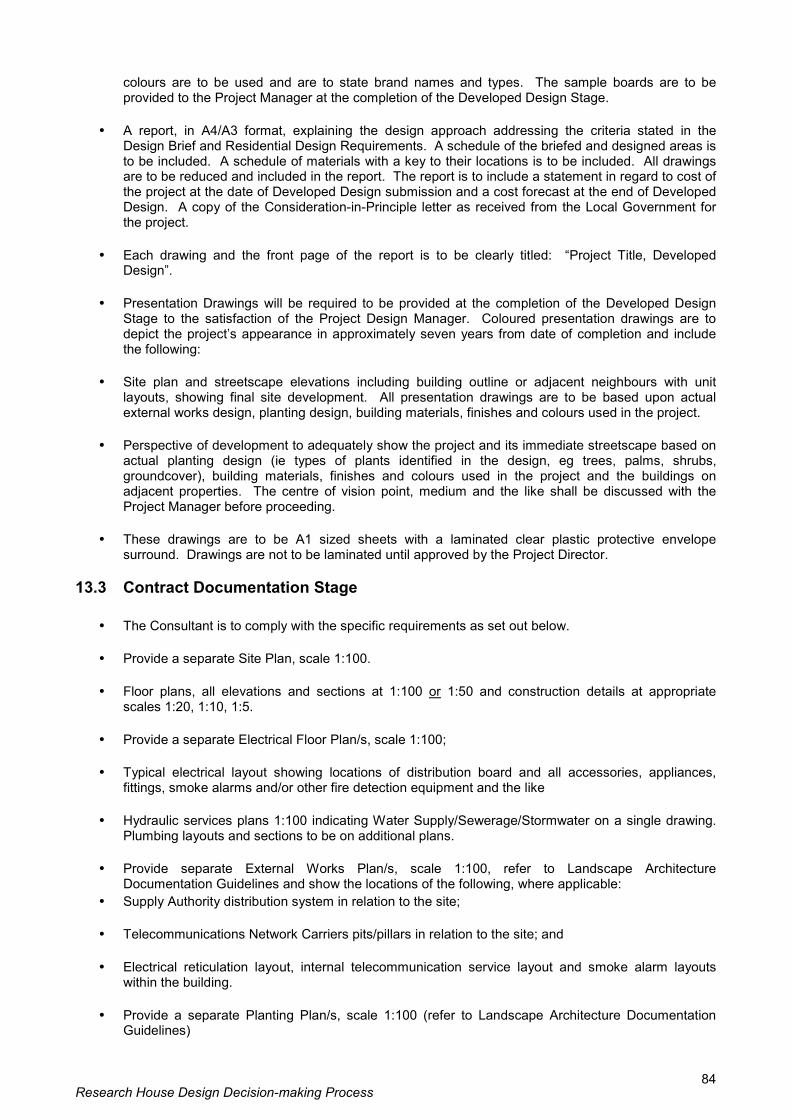
Research House Design Decision-making Process 84
colours are to be used and are to state brand names and types. The sample boards are to be provided to the Project Manager at the completion of the Developed Design Stage.
• A report, in A4/A3 format, explaining the design approach addressing the criteria stated in the
Design Brief and Residential Design Requirements. A schedule of the briefed and designed areas is to be included. A schedule of materials with a key to their locations is to be included. All drawings are to be reduced and included in the report. The report is to include a statement in regard to cost of the project at the date of Developed Design submission and a cost forecast at the end of Developed Design. A copy of the Consideration-in-Principle letter as received from the Local Government for the project.
• Each drawing and the front page of the report is to be clearly titled: �Project Title, Developed
Design�. • Presentation Drawings will be required to be provided at the completion of the Developed Design
Stage to the satisfaction of the Project Design Manager. Coloured presentation drawings are to depict the project�s appearance in approximately seven years from date of completion and include the following:
• Site plan and streetscape elevations including building outline or adjacent neighbours with unit
layouts, showing final site development. All presentation drawings are to be based upon actual external works design, planting design, building materials, finishes and colours used in the project.
• Perspective of development to adequately show the project and its immediate streetscape based on
actual planting design (ie types of plants identified in the design, eg trees, palms, shrubs, groundcover), building materials, finishes and colours used in the project and the buildings on adjacent properties. The centre of vision point, medium and the like shall be discussed with the Project Manager before proceeding.
• These drawings are to be A1 sized sheets with a laminated clear plastic protective envelope
surround. Drawings are not to be laminated until approved by the Project Director.
13.3 Contract Documentation Stage
• The Consultant is to comply with the specific requirements as set out below. • Provide a separate Site Plan, scale 1:100. • Floor plans, all elevations and sections at 1:100 or 1:50 and construction details at appropriate
scales 1:20, 1:10, 1:5. • Provide a separate Electrical Floor Plan/s, scale 1:100; • Typical electrical layout showing locations of distribution board and all accessories, appliances,
fittings, smoke alarms and/or other fire detection equipment and the like • Hydraulic services plans 1:100 indicating Water Supply/Sewerage/Stormwater on a single drawing.
Plumbing layouts and sections to be on additional plans. • Provide separate External Works Plan/s, scale 1:100, refer to Landscape Architecture
Documentation Guidelines and show the locations of the following, where applicable: • Supply Authority distribution system in relation to the site; • Telecommunications Network Carriers pits/pillars in relation to the site; and • Electrical reticulation layout, internal telecommunication service layout and smoke alarm layouts
within the building. • Provide a separate Planting Plan/s, scale 1:100 (refer to Landscape Architecture Documentation
Guidelines)

Research House Design Decision-making Process 85
• External Works Details at appropriate scales (refer to Landscape Architecture Documentation
Guidelines) • A separate Fencing Plan 1:100, may be required depending upon the complexity of the fencing
design. (Refer to Specific Scope of Works for Landscape Architectural Consultancy Services) • Pre-Tender Cost Plan. • Structural and Civil Engineering Plans and details. • Complete Specification, General Conditions of Contract. • Quality Assurance Documentation. (ie Evidence of Documentation Review) • No drawings or specification clauses are to use the words �by others�. • Consultants must retain copies of all documents for their records.
14.0 Drawings
• Drawings shall be on A series DIN dimension sheets. • Working drawings shall be on standard A1 size. • All documents shall be submitted for approval in principle at each stage. The Principal Consultant
shall not proceed with any stage of the work, or make any significant alterations to a previously approved design, without the written authority of the Project Manager.
• Notwithstanding approval to proceed being given, the Principal Consultant shall have a continuing
responsibility for the completeness and adequacy of the design and its documentation. 15.0 Authorisation of Contract Documents
15. 1 Drawing Amendments This clause refers to drawing changes which are required after the original drawing has been completed and authorised by the Consultant�s Discipline Team Leader and has been to tender. Clearly indicate the extent of the amendment either by the use of clouding (or similar), or by clearly defining the amendment in the Amendments Section of the title block and altering the drawing amendment number. When completed, the Consultant�s Discipline Team Leader shall authorise the amendment by signing in the appropriate location in the title block. Note Drawings prior to the tender issue (ie prior to authorisation by the Discipline Team Leader) should be identified by an issue number or version number in pencil. The tender will have no issue mark. Drawing issues after the tender shall be identified by an upper case alphabet character.
15.2 Authorising External Consultant�s Documents Drawings prepared by the consultant shall include the standard Project Services title block in the lower right hand corner. The Consultant shall fill in all boxes in the title block except the �Authorised for Issue� box. The Consultant�s Discipline Team Leader shall sign and date the �Discipline Leader�s� box. 16.0 AUTOCAD STANDARDS The following specifications apply to all AutoCAD drawings supplied by external Consultants. Further information detailing specific requirements will be provided upon engagement of the successful consultant. All AutoCAD drawings shall be provided in Release 12, 13 or 14 dwg format (vector format).

Research House Design Decision-making Process 86
All drawing files shall be provided to Project Services on compact disc (CD) as read only files. AutoCAD Drafting Requirements: All drawings shall comply with the following standards: AS 1100 � Technical Drawing Project Services Procedure No. PS411 � Drafting Project Services AutoCAD Standard. All drawings are to be provided on the same sheet size, preferably A1. The drawing frame shall be Xreferenced into Paperspace of each drawing. The drawings shall be created in Modelspace. Text shall be ISO3098/I Type B upright characters preferably in upper case. Minimum lettering size for A1 and A2 sheets � 3.0mm upper case, 3.5mm lower case. Minimum lettering size for A3 and A4 sheets � 2.5mm. Linetypes to be consistent with Project Services standard linetypes shall be available upon engagement. Layers to be consistent with Project Services layering standard shall be available upon engagement. Pen colours and line thicknesses to be consistent with Project Services standard shall be available upon engagement.