Embed Size (px)
Citation preview

Long-Term Behaviour and Environmentally Friendly Rehabilitation Technologies of Dams (LTBD 2017) DOI:10.3217/978-3-85125-564-5-030
203
Design and performance of drainage systems for long term
stability
W. Riemer1, F. B. Samani2
1- Consultant, Trier, Germany
2- Tamavan Consulting Engineering, Tehran, Iran
Email: [email protected]
Abstract
Drainage systems serve many tasks related to the performance of dams, auxiliary structures and reservoirs.
But for developing an appropriate design, which efficiently handles the prevailing tasks, comprehensive
information on hydrogeological parameters, hydrogeological regime and geological setting must be
elaborated. The contribution points out pitfalls experienced in this context, their potential consequences and
mentions practical precautions. Several case histories illustrate the performance of drainage systems,
successfully coping with complex conditions. But drainage systems are not only demanding in design, they
also need sustained monitoring and maintenance to assure the safety of the projects on the long term.
Keywords: Drainage, Foundation and Slope Stability, Design and Maintenance.
1. INTRODUCTION
The earliest design of gravity dams did not consider the effect of uplift pressures on their stability.
However, some masonry dams constructed at the beginning of the 20th century incorporated drains arranged
behind the upstream facing (e. g. Lister dam, Germany, 1907), similar to arrangements actually found in RCC
structures. Eventually, Casagrande (1961) stressed the importance of drainage for the stability of concrete dams
and its function in conjunction with the geology of the foundation rock. De Mello (1977, 1984) elaborated on the
subject of drainage, included embankment dams in his discussion and pointed out the relation between grout
curtain and foundation drainage. With these publications, the drainage has developed into a standard component
for all types of dams. It has proven to offer an efficient, economic and versatile tool for a wide range of purposes
as there are mainly:
control of uplift in the foundation of dams for stability against sliding and toppling
control of internal pore pressures in dams
stability of the abutments of dams, especially for concrete dams
safe handling of seepage water inside embankment dams
assistance to consolidation of foundations of dams as well as of the body of an embankment dam itself
control of uplift downstream of dams
stability of appurtenant structures (spillway, power plant, etc.) downstream of dams
control of seepage gradients in foundations and managing the hazards of internal erosion and piping
preventing deterioration of foundations by hydrochemical effects in relation with seepage
stabilizing reservoir slopes and slopes downstream of dams
preventing waterlogging downstream of dams.
Although much experience has accumulated in the application of drainage for the various purposes listed
above, the authors see the need to emphasize the importance of geological and hydrogeological investigation and
analysis to provide the basis for designing an effective and reliable system. Many geological features, geotechnical
and hydrogeological parameters are to be determined and a geotechnical-hydrogeological model must be
established. The following paragraphs, mainly from a geological point of view, discuss the methods for obtaining
the basic input, the identification of design requirements and the adjustment of designs to cope with specific site
conditions. Finally, considerations in respect of operation and maintenance of drainage systems are addressed.

Long-Term Behaviour and Environmentally Friendly Rehabilitation Technologies of Dams (LTBD 2017) DOI:10.3217/978-3-85125-564-5-030
204
2. BASIC PARAMETERS
2.1. GENERAL REQUIREMENTS
The permeability of soil or rock mass of foundation and abutments as well as of embankment materials
constitutes the most important parameter. Common practice in the investigation of dam sites estimates the
permeability from point tests: Lugeon or permeameter tests. These tests have limitations in accuracy, suffer from
random errors and may be misleading if statistics of the mean are applied to cases where extreme values are
decisive. The tests do not provide reliable information on the anisotropy of permeability (as for instance frequently
applies to varved soils). These conditions call for judgement in the selection of design parameters, and for cross
checking.
Permeability determined in the course of project studies will not necessarily apply to the performance of
the dam and its foundation because:
mechanical stresses exerted by the structures can raise or decrease the permeability
hydrojacking caused with the rising reservoir level can increase the permeability
internal erosion can raise the permeability of foundation soils, colmatation by sediments can create
seepage barriers
leaching of grout, of concrete and of soluble minerals from the foundation may raise the permeability.
Other aspects to be studied in relation with the design of a drainage system are:
the grainsize distribution of the foundation soils (for hydraulic efficiency of the drains, for finding
admissible gradients, for design of filters)
hydrochemical parameters (related to incrustation or corrosion).
Casagrande (1961) encourages application of flow nets in the design of drainage system and de Mello
points out that the foundation may have to be homogenized by grouting in order to meet the conditions, which
allow tracing of a flow net.
2.2. CASE HISTORIES
Low permeability of foundation will obstruct drainage and, accordingly, be more demanding for the
design of the system, even if little seepage water is captured. In this regard, the Tavera spillway (Dominican
Republic) suffered from an erroneous concept. A massive conglomerate with a tight argillaceous matrix forms the
foundation. During construction, the originally designed drainage system was eliminated because little seepage
was expected. Upon reservoir filling, on occasion of the inauguration ceremony, the uplift destroyed the chute.
For the Karkheh project (Iran), the assessment of the rock mass permeability posed a difficult task. Very
early in the project study, the geological investigations identified a potential problem with uplift in the alternating
horizons of conglomerate and mudstone. Lugeon tests indicated a moderate permeability for the conglomerate but
pumping tests arrived at k≈10-3m/s, which is far out of scale of the Lugeon values. Experts consulted by the
engineer questioned the representativity of the high values. In view of the uncertainty, the engineer adopted an
observational approach, providing load berms and relief wells to cope with moderate permeability and allowing
the option of substantially strengthening the defenses against high uplift pressures. Observations during reservoir
filling eventually confirmed the high permeability for the conglomerate and required remedial action.
At the Colbún project (Chile), a heterogeneous sequence of soils formed part of the reservoir rim. The
low groundwater level in the reservoir rim left a substantial part of the sequence in dry, a conditions which further
complicated the determination of the permeability. The design anticipated a permeability of 10-4m/s and a seepage
of 0.3m³/s (Noguera et al, 1988). With rising reservoir, the seepage increased drastically and emergency measures
had to be taken to prevent hydraulic failure of the reservoir rim. At full reservoir, with the strengthened drainage
system, underseepage approaches 10m³/s, about 30 times of the initially expected value. In another case,
permeameter tests in the soil deposits forming the foundation for part of the Middle Marsyangdi dam (Nepal)
suggested the existence of highly permeable layers and raised the call for the construction of a diaphragm. But the
high permeability was incompatible with conditions established by geological field surveys, the diaphragm was
rejected and observations during reservoir filling and operation justified the decision (Rissler et al., 2015). Finely
stratified sediments can be notably anisotropic in permeability, a condition which common permeability tests
cannot quantify accurately and reliably. But the anisotropy significantly affects uplift and seepage gradients in
such type of foundation and, accordingly, has to be considered in the design of the foundation and its drainage
system. The study of the Naga Hammadi barrage on the Nile in Egypt encountered typical problems in the
determination of hydrogeological parameters: permeameter tests indicated k=5x10⁻⁵ m/s, estimates based on grain
size distribution rendered an average of 6x10⁻⁴ m/s and interference pumping tests found k=10-3 m/s for the sand

Long-Term Behaviour and Environmentally Friendly Rehabilitation Technologies of Dams (LTBD 2017) DOI:10.3217/978-3-85125-564-5-030
205
and a ratio horizontal/vertical permeability >10 (Guth et al., 1988). Figure 1 demonstrates the important effect of
the anisotropy on the flow net. Mitigating the risk of hydraulic failure downstream of the barrage, the design
provided a diaphragm on the upstream side and a downstream apron with sheetpiles on the downstream side.
ksand=10-3 m/s, kh/kv=1, kgravel=2x10⁻³ m/s
ksand=10-3 m/s, kh/kv=10, kgravel=2x10⁻³ m/s
ksand=10-3 m/s, kh/kv=1, kgravel=10-3 m/s
ksand=10-3 m/s, kh/kv=10, kgravel=10-3 m/s
Figure 1: Hydrogeological FE model, probing the effect of input parameters on uplift
and seepage gradients. Foundation slab in the center, equipotential contours spaced
0.4m. A gravel layer is intercalated in the sand.
Figure 2: Failure of Malpasset arch dam foundation, attributed to uplift pressure
(Londe, 1987)
A prism of rock broke out of the foundation on the left abutment of Malpasset dam, causing the disastrous
failure of the dam. Londe (1987) attributes the failure to changes in the permeability of the rock mass, caused by
the stresses imposed by the dam – tension opening a discontinuity at the upstream heel of the dam with subsequent
jacking by the infiltrating reservoir water and compression in the direction of the thrust of the dam, reducing rock
permeability to form an “underground dam” preventing pore pressure relief (Figure 2, right).

Long-Term Behaviour and Environmentally Friendly Rehabilitation Technologies of Dams (LTBD 2017) DOI:10.3217/978-3-85125-564-5-030
206
3. DRAINAGE IN THE BODY OF DAMS
3.1. EMBANKMENT DAMS
Drainage layers constitute a standard element in homogeneous and zoned embankments. But there are
also cases with less common design features. For instance, impervious upstream facing allows adopting steep
slopes, under condition that the body of the dam drains freely. Drains will have to be provided, if this condition
is not granted. For instance, the compaction test of basalt for the Mohale dam produced fines potentially
obstructing drainage. Therefore, a drainage layer with dolerite was placed in the valley floor, which proved useful
when the concrete face cracked, drastically increasing the seepage. Foreclosing even more serious cracking at the
Paute Mazar dam (Ecuador), 175 m high in a narrow valley, required intensive compaction of the rockfill, which
left a layer of low permeability fines on the top of each lift. A central chimney drain was added to the design and
proved useful when seepage developed. A similar drain in the Porce III CFRD (Columbia) permitted steep slopes
constructed with problematic schist. If gravel with a notable proportion of fines supplies the fill for a concrete
face dam, the incorporation of a drainage system acquires particular importance. The internal drainage performed
satisfactorily on the Caracoles dam (Argentina) and was also incorporated into the body of the Misicuni dam
(Bolivia). The Bigge dam (Germany) displays a special design. With the experience of the catastrophic damage
during World War 2 of the Möhne masonry dam, an embankment with an internal reinforcement of the crest and
with an inner buffer zone was adopted. The buffer zone serves to contain excessive seepage in the event that the
upstream facing would be damaged. However, drains in the valley floor will relieve internal pressure against the
facing when the lake is drained.
Figure 3: Drains in dams with upstream facing, Mohale (ICOLD, 2009), Paute Mazar
(Cruz et al., 2009), Bigge (Heitfeld, 1973)
Figure 4 Left: drains relieving pressure in cracks of the Piedra del Aguila gravity dam
(Hidroeléctrica Piedra del Águila, Argentina). Note goose necks on drains. Right:
vertical drains in Platanovrissi RCC intercepting lift joints
3.2. CONCRETE DAMS
It is common practice to provide drains in concrete dams to collect seepage from block joints and in
RCC also from lift joints (Figure 4). But there is an apparently paradoxical application of drains to reduce seepage
from cracks in the concrete. Thermal shrinkage is a frequent cause of such cracks. When the reservoir rises, the

Long-Term Behaviour and Environmentally Friendly Rehabilitation Technologies of Dams (LTBD 2017) DOI:10.3217/978-3-85125-564-5-030
207
hydraulic pressure jacks the cracks open and seepage increases with the third power of the crack width. If this
happens, drains drilled into the crack will relieve the jacking pressure and reduce the seepage (Figure 4).
4. DRAINS FOR FOUNDATIONS, ABUTMENTS AND APPURTENANT STRUCTURES
The hydrogeological parameters are to be introduced into a model which also reflects the engineering
geology and geotechnical conditions. Several publications (Terzaghi. 1929, Casagrande 1961, de Mello 1977,
1984) emphasize the importance of geological conditions, specifically also of geological details for the
appropriate design and satisfactory performance of drainage systems (samples see Fig. 5).
a) Terzaghi (1929) b) Casagrande (1961) c) Shahid Abbaspour with vuggy zone
Figure 5: Geological conditions in the foundation of concrete dams and their effect on
uplift and the arrangement of drainage systems
4.1. CASE HISTORIES – HYDROGEOLOGICAL/GEOTECHNICAL MODEL
The design of the drainage system requires hydrogeological parameters, geotechnical characteristics and
a hydrogeological model. Developing the model may need exploratory works covering an area substantially
extending beyond the foundation area of the dam. For the Karkheh dam, early stages of geological explorations
had correctly defined the hydrogeological model, indicating the risk of uplift. But with the uncertainty regarding
the permeability, the final requirements for drainage and buttress fills were quantified concurrent with reservoir
impounding. At the Colbún dam, in addition to the uncertainty in respect of the permeability, an unforeseen
geological feature aggravated the problem. A lateral moraine, buried by fluvial and volcanoclastic soils, formed
a hydrogeological barrier downstream of the dam, creating dangerous upward gradients (see Figure 6). An
emergency action, constructing counterweight berms, 8 km of drainage ditches and 150 relief wells prevented the
failure of the dam and the reservoir rim (Noguera, 1988).
Figure 6: Seepage model for the drainage divide dam of Colbún reservoir, left expected
flow pattern, right with flow forced upward by low permeability moraine
On the contrary, for the Middle Marsyangdi project, a hydrogeological model indicated high seepage
gradients, implying a risk of erosion and suffusion in the soil foundation of the dam, and the contractor claimed
the need for a diaphragm and drainage system. However, the critically high exit gradients were an artefact, due to
incorrect placement of a barrier boundary in the FE model shortly downstream of the toe of the dam, which does
not exist in reality, as meanwhile confirmed in nearly 10 years of operation.

Long-Term Behaviour and Environmentally Friendly Rehabilitation Technologies of Dams (LTBD 2017) DOI:10.3217/978-3-85125-564-5-030
208
4.3. CASE HISTORIES – DRAINS FOR FOUNDATION STABILITY
A complex geological structure of the foundation rock frequently also produces intricate hydrogeological
conditions, difficult to unravel and requiring extensive treatment. The Thissavros dam, Greece, illustrates such
setting (Anastassopoulos et al., 2004). Faults in the metamorphic rock create compartments differing in
hydrogeological regime and requiring individual treatment. Although the dam partially rests on a slide mass, the
drainage system has secured the stability of the abutments. Budget limitations prevented the downstream
extension of the drainage system in the right valley flank and eventually a voluminous rockslide occurred there
(communication O. Papageorgiou).
Figure 7: Thissavros dam, arrangement of drainage and grouting galleries and
hydrogeological section of right abutment. Hatching represents groundwater.
A karstic foundation of a high arch dam assigns particular importance to the drainage system. In this
regard, Shahid Abbaspour dam forms a successful example. The drainage system is more comprehensive on the
right side of the valley where the structure of the rock mass is more critical for slope stability. The response
diagram demonstrates stable performance over a period of 10 years (Figure 8, right). When the reservoir level
exceeds el. 530m the seepage increases abruptly, indicating the need for a complement to the grout curtain.
Figure 8: Shahid Abbaspour dam, arrangement of drainage and grouting galleries,
sample of discharge response diagram (Mahab Ghodss – Stucky – Electrowatt
Optimization Study)
4.4. CASE HISTORIES – DRAINS PREVENTING EROSION AND DETERIORATION OF FOUNDATIONS
If the foundation is capable of developing erosion, piping, suffusion or leaching, the seepage gradients
and percolation velocities must be kept at safe limits and the drainage systems must retain soil particles. Already
in 1910, Bligh formulated relevant criteria, recently ICOLD (2015) treated the subject comprehensively.
The Casa de Piedra dam, Argentina, rests on a layer of shale, expected to act as blanket obstructing
seepage. However, a layer of vuggy limestone below the shale transfers high pressure from the reservoir to the
shale blanket. The shale is gypsiferous and smectite forms a proportion of the clay fraction. According to a
hydrochemical evaluation, the reservoir seepage would attack the gypsum and substitute the Ca-content in the

Long-Term Behaviour and Environmentally Friendly Rehabilitation Technologies of Dams (LTBD 2017) DOI:10.3217/978-3-85125-564-5-030
209
shale by Na. The process constitutes a double hazard: increasing permeability by dissolution and activating the
dispersivity of the smectite by exchanging Ca for Na. In fact, boils appeared downstream of the dam and seepage
water left efflorescence of minerals leached from the shale (Figure 9). To halt the deterioration of the shale layer,
a line of relief wells was proposed, dropping the head in the vuggy limestone just enough to keep the piezometric
level below the ground surface.
Figure 9: Casa de Piedra Dam, geological section of foundation, boils, efflorescence
Figure 10: Daule Peripa reservoir rim dike, relief wells showing erosion and settlement
cracks.
An 18 km long auxiliary dam was constructed on the reservoir rim of the Daule Peripa reservoir. It rests
on a complex series of volcanoclastic and fluvial soils. At depressions in the reservoir rim, drainage wells are
arranged, intended to relieve potentially hazardous uplift pressures. With a few exceptions, the drainage system
has performed satisfactorily for more than 20 years. Very few wells have indications of erosion and/or settlements
(Figure 10). In these places remedial measures will have to be taken.
5. DRAINS FOR AUXILIARY STRUCTURES
Uplift related with reservoir seepage can affect the stability of structures downstream of a dam. This
conditions may apply to spillways and powerhouses. The destruction of the Tavera spillway by uplift was
mentioned above. For Karkheh, the design provided ample drainage systems for the spillway chute and the
powerhouse. With reservoir filling, further measures were taken for reduction of uplift pressures at the
powerhouse.
In view of the notable karstification at the Ataturk dam site, the design provided a combination of a
grouted box with external and internal drains for the powerhouse (Figure 11, Riemer et al., 1991). After reservoir
filling, the drainage system was further strengthened, extending a gallery upstream of the plant. It is now in
operation for more than 25 years.

Long-Term Behaviour and Environmentally Friendly Rehabilitation Technologies of Dams (LTBD 2017) DOI:10.3217/978-3-85125-564-5-030
210
Figure 11: Management of uplift pressure at Ataturk powerhouse. Hatching represents
grouted rock.
6. DRAINS FOR RESERVOIR SLOPE STABILITY ICOLD Bulletin 124 mentions several case histories where drainage offered a reliable and economic
solution for problems of reservoir slope stability, including such monumental tasks as Dutchmans Ridge at Mica
Dam and the Cromwell Gorge in New Zealand. Along the Cromwell Gorge, 11 large landslides had to be stabilized
before impounding of Lake Dunstan could start. The task was accomplished within 2.5 years and at a cost of 250
million US$, mainly by drainage measures. The economical and technical success was achieved by a well-
organized team of 50 dedicated professionals. The team managed to unravel the complex geological and
hydrogeological conditions of the landslides (see sample in Figure 12) and found efficient solutions for the
stability problems. Impounding started in 1992 and the reservoir slopes have performed fully satisfactorily.
Figure 12: Geological and hydrogeological conditions at Cairnmuir Slide. Mainly the
drainage of the sub-basal confined aquifer stabilized the slide. Hatching marks
groundwater below main failure plane.
7. OPERATION AND MAINTENANCE OF DRAINAGE SYSTEMS
Frequently applied design criteria for the stability of dams require a safety factor equal to 1 with the
drainage system not functioning. However, there are cases where this condition is not viable and which,
accordingly, call for circumspect measures to either guarantee the efficiency of the drainage system or,
alternatively, manage the risks potentially associated with a failure of the drainage system. Two case histories
illustrate this condition:
Lake Dunstan in New Zealand and Piedra del Aguila in Argentina.
Hydrogeological instrumentation of the Lake Dunstan Landslides comprises:
63 discharge gauges, 733 piezometers, 22 multi-position Westbay piezometers.
Data from primary instruments are transmitted in real time, introduced into a data base, automatically
checked for consistency, checked against alarm criteria and, if exceeding alarm or alert level thresholds,
immediately communicated to the operating staff. Assisted by various modules connected to the data base – e. g.
location maps, diagrams – operating staff takes remedial measures or initiates pre-defined emergency action.
Long-Term Behaviour and Environmentally Friendly Rehabilitation Technologies of Dams (LTBD 2017) DOI:10.3217/978-3-85125-564-5-030
211
Routine checks verify the efficiency of the drain holes to determine the need for flushing or replacement. An
independent panel periodically reviews the conditions of the monitoring system and the performance of the
landslides.
Figure 13: Drainage system in buried valley under left abutment of Piedra del Águila
Dam
On the left abutment of Piedra del Águila Dam, Argentina, the stabilization measures include drainage
by gravity as well as by pumped tube wells (Figure 13). The area is controlled by video, instrumentation data are
automatically transmitted to the operation center of the powerplant (with two independent lines), the well field
has a multiple of the normally required capacity, there are two lines of power supply and additional emergency
power supply. ORSEP, the Argentinian authority in charge of dam safety, has developed plans for emergency
action and imposes periodic safety inspection by independent engineers.
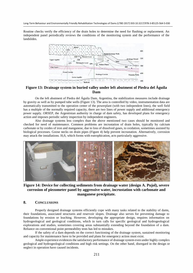
Also drainage systems less complex than the above mentioned two cases should be monitored and
checked for need of maintenance. Common problems are incrustation of drain holes, typically by calcium
carbonate or by oxides of iron and manganese, due to loss of dissolved gases, to oxidation, sometimes assisted by
biological processes. Goose necks on drain pipes (Figure 4) help prevent incrustation. Alternatively, corrosion
may attack the installations. H2S, which forms with eutrophication, acts particularly aggressive.
Figure 14: Device for collecting sediments from drainage water (design A. Pujol), severe
corrosion of piezometer panel by aggressive water, incrustation with carbonate and
manganese precipitate.
8. CONCLUSIONS
Properly designed drainage systems efficiently cope with many tasks related to the stability of dams,
their foundations, associated structures and reservoir slopes. Drainage also serves for preventing damage to
foundations by erosion or leaching. However, developing the appropriate design, requires information on
hydrogeological and geological conditions, which in turn calls for specific geological and hydrogeological
explorations and studies, sometimes covering areas substantially extending beyond the foundation of a dam.
Reliance on conventional point permeability tests has led to mistakes.
If the safety of a dam depends on the correct functioning of the drainage system, sustained monitoring
and capacity for maintenance have to be provided and plans for emergency action must exist.
Ample experience evidences the satisfactory performance of drainage system even under highly complex
geological and hydrogeological conditions and high risk settings. On the other hand, disregard in the design or
neglect in operation have caused incidents.

Long-Term Behaviour and Environmentally Friendly Rehabilitation Technologies of Dams (LTBD 2017) DOI:10.3217/978-3-85125-564-5-030
212
9. ACKNOWLEDGMENT
The authors wish to express their gratitude to the many professionals with whom they had the privilege
of working on hydro projects.
10. REFERENCES
1. Anastassopoulos, K., Hoek, E., Milligan, V., Riemer, W. (2004), “Thissavros hydropower plant. Managing
geotechnical problems in the construction,” Proc. 5th Int. Conf. Case Histories in Geotech. Eng., paper 2-63
2. Bligh, W. G. (1910), “Practical design of irrigation works”, Second edition, Constable, Edinburgh
3. Brown, R., Gillon, M., Riemer, W. (1993), “Sanierung von Rutschungen am Dunstan Stausee, Clyde
Wasserkraftwerk, Neuseeland“, Ber. 9. Nationale Tagung für Ingenieurgeologie, Garmisch Partenkirchen,
1993, Geotechnik, Sonderheft, pp 93-102.
4. Casagrande, A. (1961), “Control of seepage through foundations and abutments of dams” 1rst Rankine Lecture,
Geotechnique 11,3, p 161-181
5. Casagrande, A. (1965). “Role of calculated risk in earthwork and foundation engineering “, Jnl ASCE 91, SM4,
Part 1, l-40.
6. Cruz, P. T., Materón, B., Freitas, M., (2009), “Concrete face rockfill dams”, 448 p
7. Guth, W., Riemer, W. (1998) “Geotechnical and hydrogeological site characterization for the Naga Hammadi
barrage on the river Nile “, International conference IAEG 1998, pp 3275-3286
8. Heitfeld, K. H. (1991), “Talsperren“ Lehrbuch der Hydrogeologie Band 5, Bornträger, 468 p
9. ICOLD (2000), “Reservoir landslides, investigation and management”, Bulletin 124
10. ICOLD (2009), “10th benchmark workshop on numerical analysis of dams “
11. ICOLD (2015), “Erosion, Processes and Engineering Assessment”, Bulletin 164 Volume 1,
12. Londe, P. (1987), “The Malpasset dam failure”, Eng. Geol. 24, pp 295-329
13. de Mello, V.F.B. (1977), “Reflecting on design decisions of practical significance to embankment dams” 17th
Rankine Lecture, Geotechnique 27, 3, p 279-355
14. de Mello, V.F.B. (1984), “Concrete gravity dam foundations: an open case of geomechanical interaction,
structure-foundation and theory-practice” 4th Australia-New Zealand Conf. Geomech.
15. Noguera, G., Garcés, E. (1988) “Colbún reservoir seepage “, Proc. 16th Congr. ICOLD, C18, Vol III, pp
1223-1235
16. Riemer, W., Andrey, J. D. (1991) “Baugrundbehandlung am Atatürk Damm“, Ber. 8. Nationale Tagung für
Ingenieurgeologie, Berlin, 1991, pp 167-174
17. Rissler, P., Riemer, W. (2015): “Handling a complex foundation below the rockfill dam at the Middle
Marsyangdi Hydroelectric Scheme, Nepal “, Proc. 25th Congr. ICOLD, Q.98-R.26
18. Terzaghi, K. 1929. “Effect of minor geological details on the safety of dams”, American Institute of Mining
and Metallurgical Engineers. Technical Publication 215, p. 30.


![Long term effects of manual lymphatic drainage and active ...€¦ · Manual lymphatic drainage (MLD) is also widely used in women with lymphedema [16]. Lym-phoscintigraphy studies](https://img.dokumen.tips/doc/110x75/5f2bc3d82c031e356a06ce87/long-term-effects-of-manual-lymphatic-drainage-and-active-manual-lymphatic-drainage.jpg)