Embed Size (px)
Citation preview

Page 584
Design and Optimization of a flywheel for the 4-Cylinder
Diesel Engine
Appala Narasimha Murthy B
M-Tech student
Department of Mechanical Engineering
Sanketika Vidya Parishad Engineering College
P.Srinivas Reddy
Assistant Professor
Department of Mechanical Engineering
Sanketika Vidya Parishad Engineering College
Abstract
A flywheel releases stored energy by applying torque
to a mechanical load, thereby decreasing the
flywheel's rotational speed. This would be much
essential under failure consideration due to stresses
resulting from centrifugal effects. Different designs
existed all intended to be easy and most economical
to produce. The project involves the design and
analysis of flywheel to minimize the radial and
tangential stresses, the flywheel is subjected to a
constant rpm. The objective of present work is to
design and optimize the flywheel for the best
material. Evaluation of the materials has been done
by comparing the materials one on the other, out of
which carbon fiber exhibited better results. Carbon
fiber and Magnesium alloys are the best materials to
be considered, as carbon fiber is light in weight and
efficient. Magnesium alloy is equivalently efficient
and economical as that of carbon fibre. Static
analysis has been observed by applying angular
velocity on to the flywheel. Analytical calculation as
well as simulation is done for design of flywheel by
varying different material on Ansys.
Keywords: Flywheel, Radial Stresses, Tangential
Stress
1. Introduction
A basic machine motive gear mechanism or auto gear
mechanism contains of varied transmission elements
like gears, shafts and alternative components that
operate along to modify the movement of associate in
nursing automobile. Automobile or automotive gear
mechanism consists of varied devices that facilitate in
transmission power from the engine through the drive
shaft to the driving axle of associate in nursing
automobile. Gears, brakes, clutch, coupler and
alternative machine transmission components work
along for remodeling the speed quantitative relation
between the engine and wheels of a vehicle. The
machine gear mechanism incorporates varied
elements, that area unit hooked up to the rear of the
engine and used for distributing the facility from the
engine to the drive wheels.
1.1 Flywheel:-
A flywheel is a machine component which is used in
machines serves as a reservoir which stores energy
during the period when the supply of energy is more
than the requirement and releases it during the period
when the requirement of energy is more than supply.
For example, in I.C. engines, the energy is developed
only in the power stroke which is much more than
engine load, and no energy is being developed during
the suction, compression and exhaust strokes in case of
four stroke engines. The excess energy is developed
during power stroke is absorbed by the flywheel and
releases it’s to the crank shaft during the other strokes

Page 585
in which no energy is developed, thus rotating the
crankshaft at a uniform speed. The flywheel is located
on one end of the crankshaft and serves two purposes.
First, through its inertia, it reduces vibrations by
smoothing out the power stroke as each cylinder fires.
Second, it is the mounting surface used to bolt the
engine up to its load.
1.2 Function of a Flywheel:-
The main function of a fly wheel is to smoothen out
variations in the speed of a shaft caused by torque
fluctuations. If the source of the driving torque or load
torque is fluctuating in nature, then a flywheel is
usually called for. Many machines have load patterns
that cause the torque time function to vary over the
cycle. Internal combustion engines with one or two
cylinders are a typical example. Piston compressors,
punch presses, rock crushers etc. are the other systems
that have fly wheel. Flywheel absorbs mechanical
energy by increasing its angular velocity and delivers
the stored energy by decreasing its velocity.
Fig.1.1. flywheel function
1.3 Structure of Flywheel:
The geometry of a flywheel may be as simple as a
cylindrical disc of solid material, or may be of spoked
construction like conventional wheels with a hub and
rim connected by spokes or arms Small fly wheels are
solid discs of hollow circular cross section. As the
energyrequirements and size of the flywheel increases
the geometry changes to disc of central hub and
peripheral rim connected by webs and to hollow
wheels with multiple arms.
2. Literature Review:
Sushama G.Bawane et al. [1], proposed flywheel
design .They study different types of flywheel & use
different types of material for the analysis purpose. By
using FEA analysis suggested the best material for the
flywheel.
Sagar M. Samshette [11] works on design Solid, Rim,
Section-cut and six arm type flywheel maintaining
constantweight. And simultaneously we calculate
moment of inertia and kinetic energy of respective
flywheel. He conclude that six arm type flywheel store
more amount of kinetic energy as compare to solid,
rim and section cut flywheel.
S. M. Dhengle et al. [2] shows the comparison
between analytical stresses and FE stresses in Rim by
varying no. of arms& comparison between FE stresses
on arm and analytical calculated bending stresses in
arms. They also had seen that as a number of arms
increases from 4 to 8, the stresses in the arms go on
reducing. This may be due to sharing of load by larger
no. of arms shows the comparison of FE stresses and
analytical bending stresses near the hub end of arm for
4, 6 and 8 arms flywheel under the influence of
tangential forces on rim.PROBLE STATEMENT
3. Problem Statement:
3.1 Research Needs:
The efficiency of a flywheel is determined by the
amount of energy it can store per unit weight. As the
flywheel’s rotational speed or angular velocity is
increased, the stored energy increases however, the

Page 586
centrifugal stresses also increase. If the centrifugal
stresses surpass the tensile strength of the material, the
flywheel will fly apart. Thus, the tensile strength is an
upper limit to the amount of energy that aflywheel can
store.
Traditionally, flywheels are made of cast iron. From
design considerations, because cast iron fly wheels are
the cheap in cost, it can be given any complex shape
without involving machining operations and cast iron
flywheel has excellent ability to damp vibrations.
However, cast iron has poor tensile strength compared
to steel. The failure of cast iron flywheel is sudden and
total. The machinability of cast iron flywheel is poor
compared to steel flywheel. More recently, flywheels
are made of high strength steels but they are limited to
revolutions at 10,000 rpm.
Now-a-days cast iron is replaced by carbon fiber
reinforced plastics due to the high tensile strength
produced by the carbon fiber when compared to that
with cast iron. Carbon fiber reinforced plastic (CFRP)
Graphite-Fiber Reinforced Polymer (GFRP) is
considered as an excellent choice for flywheels fitted
on modern car engines due to rotating mass made of
fiber glass resins or polymer materials with a high
strength-to-weight ratio, a mass that operates in a
vacuum to minimize aerodynamic drag, mass that
rotates at high frequency, air or magnetic suppression
bearing technology to accommodate high rotational
speed 100000 rpm. But the drawback of carbon fibre
reinforced plastics is that the cost of it comparatively
more. Therefore the overall cost of the fabrication also
increases.
Research has begun in this field about the use of
different materials which places a good substitute for
the carbon fiber reinforced plastics.
Taking a disc type flywheel of 4 strokes, 4 cylinder
diesel engines, which is used to transmit the power of
2.25 kW at 2740 rpm. It has to be design and
optimization by changing the materials. By identify the
stress and deformations in flywheel from Theoretical
and Numerical. As per given below inputs, Analysis
which is best material for given design.Validate results
by comparing theoretical and Numerical and plot best
material for use as given design data.
3.2 Aspects Of Proposed Work:
The proposed research work is intended to exploit the
advantages of using different materials in the design of
flywheel and different properties of them are studied
both theoretically and numerically. This provides basic
understanding the behavior of the various materials
and response in the following aspects are studied
Variations in their Radial and Tensile stresses
of the various materials along the radius of the
flywheel and comparing one on another.
Variations in their Radial and Tangential
strains of the various materials along the radius
of the flywheel and comparing one on another.
Von Mises stress of the materials.
Deformations of the materials.
4. Flywheel Design:
Flywheels are generally used for kinetic energy storage
and have been around since the early times of man.
Every object rotating around an axis stores some
amount of kinetic energy and could in theory be called
a flywheel. But the word flywheel is usually used for
constructions whose main purpose is the storage of
kinetic energy through rotation. This has led to the
convention that the term flywheel describes a rotating,
cylindrical object, usually of considerable mass, whose
main purpose is to store energy or to increase the
moment of inertia of a given system.
4.1 Design Approach
There are two stages to the design of a flywheel.
First, the amount of energy required
for the desired degree of smoothening must be
found and the (mass) moment of inertia needed to
absorb that energy determined.

Page 587
Then flywheel geometry must be
defined that caters the required moment of inertia
in a reasonably sized package and is safe against
failure at the designed speeds of operation.
4.2 Design Parameters:
Flywheel inertia (size) needed directly
depends upon the acceptable changes in the speed.
4.2.1 Speed fluctuation:
The change in the shaft speed during a cycle
is called the speed fluctuation and is equal to ωmax-
ωmin
Fl = ωmax − ωmin
We can normalize this to a dimensionless ratio by
dividing it by the average or nominal shaft speed
(ωave).
Cf= (ωmax - ωmin)/ω
Where
Cf=coefficient of speed fluctuation
ωave=Average or mean
ω= nominal angular velocity
The coefficient is a design parameter to chosen
by the designer and it must be small.
4.2.2 Design equation:
The kinetic energy in rotating system is given by
K.E = 𝟏
𝟐 Iω
2
The change in KE is given as K.E = E2-E1 = 𝟏
𝟐Im (𝛚𝐦𝐚𝐱
2 − 𝛚𝐦𝐢𝐧
2)
𝛚𝐚𝐯𝐠 =
(𝛚𝐦𝐚𝐱 + 𝛚𝐦𝐢𝐧)
𝟐
K.E = 𝟏
𝟐𝐈𝐒 (2𝛚𝐚𝐯𝐠) (𝐂𝐟𝛚𝐦𝐢𝐧
2) = E2-E1
Thus the mass moment of inertia Imneeded in the
entire rotating system in order to obtain selected
coefficient of speed fluctuation is determined using the
relation
K.E = 𝟏
𝟐𝐈𝐒 (2𝛚𝐚𝐯𝐠) (𝐂𝐟𝛚𝐚𝐯𝐠)
𝐈𝐒=K.E/ (𝐂𝐟 ωavg2)
For solid disc geometry with inside radius riand
outside radius ro , the mass moment of inertiaIm is
𝐈𝐦= mk2 =
𝐦
𝟐[(𝐫𝐨)𝟐+(𝐫𝐢)
𝟐]
The mass of a hollow circular disc of constant
thickness t is
m = W/g = 𝛒𝛑 [(𝐫𝐨)𝟐+(𝐫𝐢)𝟐]t
From the above two equations
Im= 𝛑𝛒
𝟐[(𝐫𝐨)𝟒+(𝐫𝐢)
𝟒]t
The above equation can be used to obtain appropriate
flywheel inertia Imcorresponding to the known energy
change K.E for a specific value coefficient of speed
fluctuation 𝐂𝐟,
4.2.3Torque Variation and Energy
The required change in kinetic energy K.E is obtained
from the known torque time relation or curve by
integrating it for one cycle.
𝐊. 𝐄 = (𝐓𝟏 − 𝐓𝐚𝐯𝐠)𝐝𝛉𝛉@𝛚𝐦𝐚𝐱
𝛉@𝛚𝐦𝐢𝐧
Stresses in Flywheel: Flywheel being a rotating disc,
centrifugal stresses acts upon its distributed mass and
attempts to pull it apart. Its effect is similar to those
caused by an internally pressurized cylinder
Radial stress 𝛔𝐫= 𝛒𝛚𝟐 𝟑 + 𝛍
𝟖 𝐫𝐨
𝟐 + 𝐫𝐢𝟐 −
𝐫𝐨𝟐𝐫𝐢
𝟐
𝐫𝟐 −
𝐫𝟐
Page 588
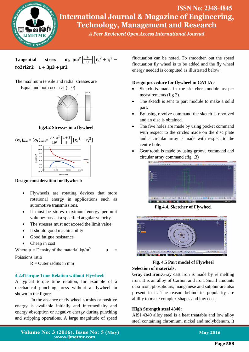
Tangential stress 𝛔𝛉=𝛒𝛚𝟐 𝟑 + 𝛍
𝟖 𝐫𝐨
𝟐 + 𝐫𝐢𝟐 −
𝐫𝐨𝟐𝐫𝐢𝟐𝐫𝟐 − 𝟏 + 𝟑𝛍𝟑 + 𝛍𝐫𝟐
The maximum tensile and radial stresses are
Equal and both occur at (r=0)
fig.4.2 Stresses in a flywheel
(𝛔𝐫)max= (𝛔𝐭)max= 𝛒 × 𝛚𝟐
𝟏𝟎𝟔 𝛍 + 𝟑
𝟖 [𝐫𝐨
𝟐 − 𝐫𝐢𝟐]
Design consideration for flywheel:
Flywheels are rotating devices that store
rotational energy in applications such as
automotive transmissions.
It must be stores maximum energy per unit
volume/mass at a specified angular velocity.
The stresses must not exceed the limit value
It should good machinability
Good fatigue resistance
Cheap in cost
Where = Density of the material kg/m3 µ =
Poissions ratio
R = Outer radius in mm
4.2.4Torque Time Relation without Flywheel:
A typical torque time relation, for example of a
mechanical punching press without a flywheel in
shown in the figure.
In the absence of fly wheel surplus or positive
energy is available initially and intermedialty and
energy absorption or negative energy during punching
and stripping operations. A large magnitude of speed
fluctuation can be noted. To smoothen out the speed
fluctuation fly wheel is to be added and the fly wheel
energy needed is computed as illustrated below:
Design procedure for flywheel in CATIA:-
Sketch is made in the sketcher module as per
measurements (fig 2).
The sketch is sent to part module to make a solid
part.
By using revolve command the sketch is revolved
and an disc is obtained.
The five holes are made by using pocket command
with respect to the circles made on the disc plate
and a circular array is made with respect to the
centre hole.
Gear tooth is made by using groove command and
circular array command (fig .3)
Fig.4.4. Sketcher of Flywheel
Fig. 4.5 Part model of Flywheel
Selection of materials:
Gray cast iron: Gray cast iron is made by re melting
iron. It is an alloy of Carbon and iron. Small amounts
of silicon, phosphours, manganese and sulphur are also
present in it. The reason behind its popularity are
ability to make complex shapes and low cost.
High Strength steel 4340:
AISI 4340 alloy steel is a heat treatable and low alloy
steel containing chromium, nickel and molybdenum. It

Page 589
has high toughness and strength in the heat treated
condition AISI 4340 alloy steel has good ductility and
formability in the annealed condition.
Carbon fiber reinforced plastic:
Carbon fibers are usually combined with other
materials to form a composite. When combined with
a plastic resin and wound or molded it forms carbon-
fiber-reinforced polymer which has a very
high strength-to-weight ratio, and is extremely rigid
although somewhat brittle. However, carbon fibers are
also composited with other materials, such as with
graphite to form carbon-carbon composites, which
have a very high heat tolerance.
Magnesium alloys (AZ91A):
Magnesium and magnesium alloys are nonferrous
metals with low density, good ductility, moderate
strength and good corrosion resistance. Its high
specific toughness and rigidity, good machinability,
castability and weldability with known methods are
maked it attractive for industry. These magnesium
alloys have a relatively low density and can help
improve fuel efficiency.
Titanium Alloys(6Al4V):
Titanium isa “formidable” material having high
strength and toughness. Titanium is an abundant earth
element, but it is difficult to refine. Titanium is quite
expensive, and since it is not widely used, the
introduction of a single new product can result.
Designing with titanium taking all factors into account
has resulted in reliable, economic and more durable
systems and components, which in many situations
have substantially exceeded performance and service
life expectations.
Beryllium alloy:
Beryllium is as an alloying element, that are used to
make components, which are inert, stable, and do not
give off emissions during use. Beryllium-containing
alloys are only used in critical locations in products
where they provide a design solution based upon
reliability, miniaturization, improved energy
management and /or extending the service life.
Table.: Materials and their properties
Table: calculations of Design parameters of the
flywheel for various materials

Page 590
Part model of Flywheel
Complete meshing of flywheel
Boundary conditions of flywheel in Ansys
5. Results & Discussions
5.1 Results from Theoretical calculations:
Comparison of mass of the flywheel
Comparison of Kinetic Energy of the flywheel
Radial stresses of the Flywheel from theoretical
calculations
Tangential stresses of the Flywheel
theoretical calculations
Material 1: Beryllium Alloy
10.81127
10.40931 6.2372
72 4.019575 2.4117
452.2176
97
02468
1012
Mas
s in
kg
4413.135
4249.057
2546.039
1640.781
984.4686
905.2584
0
5000K
ine
tic
Ene
rgy
0
5
0 50 100 150Stre
ss i
n M
Pa
Radius in mm
0
20
0 50 100 150
Stre
ss in
M
Pa
Radius in mm
BE-Al
CFRP
GCI

Page 591
Deformation Be-Alloy
Equivalent stresses of Be-Alloy
Equivalent strains of Be-Alloy
Radial stresses of Be-Alloy
Tangential stresses of Be-Alloy
Radial and tangential strains of Be-Alloy
Results of Radial Stresses from Ansys
Results of Tangential Stresses from Ansys
Results from Ansys
0.00
2.00
4.00
6.00
0.00100.00200.00S
tres
s in
MP
a
Radius in mm
BE-Al
CFRP
GCI
HSS
MG-AL
0.00
5.00
10.00
0.00100.00200.00
Str
ess
in M
Pa
Radius in mm
BE-Al
CFRP
GCI
HSS
MG-AL

Page 592
Total deformation of the flywheel vs. materials
from FEM
Radial Stresses of the flywheel vs. materials from
FEM
Tangential Stresses of the flywheel vs. materials
from FEM
Von Mises Stresses of the flywheel vs. materials
from FEM
Radial Strain of the flywheel vs. materials from
FEM
Tangential Strain of the flywheel vs. materials from
FEM
Deformations of the flywheel vs. materials
comparing the Ansys and Theoretical results
4.06E-03
2.29E-03
2.02E-03
1.97E-03
6.86E-04
5.67E-04
0.00E+002.00E-034.00E-036.00E-03
G C
I
Ti A
lloy
Mg-
Allo
y
H S
S
Be
allo
y
CFR
P
De
form
atio
n in
m
m
4.76 4.393.01
1.54 1.12 0.97
0.002.004.006.00
Stre
ss in
MP
a
8.81 8.535.13
3.38 1.98 1.81
0.00
5.00
10.00
Stre
ss in
MP
a
12.9112.646.70 5.49
2.63 2.62
0.005.00
10.0015.00
Stre
ss in
MP
a
3.07E-05
1.39E-05
1.53E-05
1.39E-05
1.36E-05
4.03E-06
0.00E+00
2.00E-05
4.00E-05
Stra
in
6.27E-05
5.38E-05
3.44E-05
2.99E-05
3.04E-05
8.66E-06
0.00E+00
5.00E-05
1.00E-04
Stra
in
0.00E+00
5.00E-04
1.00E-03
1.50E-03
2.00E-03
2.50E-03
3.00E-03
3.50E-03
4.00E-03
4.50E-03
5.00E-03
De
form
atio
n in
mm
Ansys
Theory
0.002.004.006.00
Stre
ss in
MP
a
Radial …

Page 593
Radial stressof the flywheel vs. materials
comparing the Ansys and Theoretical results
Tangential stressesof the flywheel vs. materials
comparing the Ansys and Theoretical results
Radial strain of the flywheel vs. materials
comparing the Ansys and Theoretical results
Tangential strain of the flywheel vs. materials
comparing the Ansys and Theoretical results
6. Conclusion :
This optimization is carried out between the various
materials, to find the minimum mass and respective
values of stresses along radius by conducting static
analysis.
From the analysis, it is clear that, Carbon Fiber
is the best material it is having low mass as compared
to the other material and also the stresses and strains in
the carbon fiber is also low compared to the other
materials.
Magnesium alloy is also the best material
which is capable of withstanding stresses that are
developed within the flywheel. From the analysis, by
using the magnesium alloys we can reduce the stresses
77% when compared to H S steel, 75% when
compared to cast iron, also by using Magnesium alloys
we can reduce the mass upto 75%.
7. References
1. S.G Bawane, “Analysis and optimization of
flywheel” International journal of mechanical
engineering & robotics research, ISSN2278 – 0149,
Vol. 1, No. 2, July 2012.
2. S. M. Dhengle “Investigation of stresses in
arm type rotate in flywheel” International Journal of
Engineering Science and Technology (IJEST).
3. M. Lava Kumar, “Design and analysis of light
weight Motor vehicle flywheel” International Journal
of Computer Trends and Technology (IJCTT) –
volume 4 Issue 7–July 2013
4. Akshay P., Gattani G.K, 2013. Analysis of
Flywheel. Modern Engineering and Research,
pp.Vol.3, ISSN: 2249-6645 1097-1099
5. D.Y. Shahare, “Design Optimization of
Flywheel of Thresher using FEM.” Advanced
Materials Manufacturing & Characterization, Vol3
Issue 1 (2013).
6. Hongliang Chen,Changsheng Zhu and Peng
Ye “A Comparison of Analysis Flywheel Stress
Distributions Based on Different Material”Applied
Mechanics and Materials Vols. 536-537 (2014) pp
1291-1294
0
5
10
15
Stre
ss in
MP
a Tangenti…
0.00E+00
5.00E-06
1.00E-05
1.50E-05
2.00E-05
2.50E-05
3.00E-05
3.50E-05
Stra
in
Radial strain …
0.00E+00
2.00E-05
4.00E-05
6.00E-05
8.00E-05
1.00E-04
1.20E-04
Stra
in
Tangent…

Page 594
7. JohnA.Akpobi&Imafidon A.Lawani
“computer-aided-designs of Flywheel” Volume 37
Issue 4, April 2006, ISSN: 0965-9978
8. S. Saha “Computer aided design & analysis on
flywheel for greater efficiency” International Journal
of Advanced Engineering Research and Studies E-
ISSN2249– 8974.
9. Mouleeswaran Senthil Kumar and Yogesh
Kumar “optimization of flywheel materials using
genetic algorithm” Acta Technical Corvininesis -
Bulletin of Engineering;Oct-Dec2012, Vol. 5 Issue 4,
p37
10. AswinInbarajJaison and Karuppasamy
“Design and Optimization of Flywheel for Automobile
Applications” ISSN 0973-4562 Vol. 5 No.1 (2015)
11. Sagar M. Samshette “Investigation of Smart
Profile of Flywheel” Volume 5 Issue 4 August 2015,
ISSN: 2319 – 1058
12. Kobia K. Lawrence and Mao Ya “Finite
element analysis of radial stress distribution on
axisymmetric variable thickness Dual Mass Flywheel
using ANSYS” ISSN 2222-1727 Vol.5, No.4, 2014
13. V.Antonelli, P. He and H. Baie “Challenges
indesign of high energy storage flywheels made of
composite material”
14. S.M. Arnold, A.F. Saleeb and N.R. AI-Zoubi
“Deformation and Life Analysis of Composite
Flywheel Disk and Multi-Disk Systems” NASA/TM-
2001-210578
Text books references
1. A Test book on Machine Design by
R.S.Khurmi&J.K.Gupta, Eurosia publishing house,
PVT, LTD, Ram Nagar, New Delhi-110055.
2. Finite Elements in Engineering by Tirupathi R.
Chandrupatla& Ashok D. Belegundu, Third Edition,
PHI Learning PVT. LTD. New Delhi 110001, 2012.
3. Machine Design” by B.D. Shiwalkar.
4. Design of machine elements by V.B Bhandari,
Tata McGraw hill publications
5. Machine design by N.C Pandya and C.S.Saha,
Charotar publishing house
Author Details:
Appala Narasimha Murthy B is a P.G student of
Mechanical Department of Sanketika Vidya Parishad
Engineering College. He has done his B.Tech from
Vijay Rural Engineering College (VREC), Nizambad,
Andhra Pradesh. India.
Mr. P.Srinivas Reddy is born in Andhra Pradesh,
India. He has received M.Tech. [CAD /CAM] from
GITAM university Visakhapatnam. AP, INDIA. He
is working as Assistant professor in Mechanical
Engineering dept,Sanketika Vidya Parishad
Engineering College,and Visakhapatnam. India