Embed Size (px)
Citation preview

PARAMETRIC DESIGN OF A FLYWHEEL FOR AN ELECTRIC PUNCH PRESS
By
Prashant Dhakal
A thesis submitted to the faculty of The University of Mississippi in partial fulfillment of the
requirements of the Sally McDonnell Barksdale Honors College.
Oxford, MS
May 2021
Approved By
______________________________
Advisor: Dr. Tejas Pandya
______________________________
Reader: Dr. Taiho Yeom
______________________________
Reader: Dr. Wen Wu

ii
© 2021
Prashant Dhakal
ALL RIGHTS RESERVE

iii
DEDICATION
This thesis is dedicated to everyone who guided and encouraged me throughout the year.
Thank you.

iv
ACKNOWLEDGEMENTS
I would like to thank Dr. Tejas Pandya for allowing me to embark on this exciting project. His
guidance, support, insights, and particularly, his mentorship proved to be invaluable to producing
this thesis.
v
ABSTRACT
Almost all designs start with a design requirement. These may be weight, volume,
clearance, and even custom calculations. To find a solution that meet these requirements often
involve tedious and time-consuming iterations. Once the solution has been found, the design must
be optimized to find the best possible solution. Finding the ‘best possible design’ requires
substantial time and effort dedicated iterating and analyzing the potential model solutions. This is
where Parametric design comes in play. The parametric design aids in specifying the key
parameters of the design and makes changes interactively, with the model updating automatically.
The purpose of this project was to implement parameters to the design of flywheel, which powers
a punch press. A punch press is a machine that is used to punch a hole on a piece of material by
applying pressure to a die in which the workplace is held. The design of flywheel varies with its
application. Depending on its application, a flywheel’s design must be optimized. The project
employs flywheel with a punch press, so the flywheel needs to be matched according to the work
expected, the amount of energy needed at a given rate to accomplish the machining operation, and
the size and the number of holes punched by the press. The designing was performed with the help
of 3D Solid Modeling software CREO Parametric 7.0. More specifically, the behavioral modeling
feature was used. An Excel sheet containing all the parameters was linked with CREO and
changing the input values in Excel updated the model. Thus, with the help of CREO, a feasible
design of the flywheel was drafted. Along with this, several shapes of flywheel were studied and
compared to find the best shape for the press.
vi
TABLE OF CONTENTS
LIST OF FIGURES
vii
LIST OF ABBREVIATIONS
viii
INTRODUCTION
1
CHAPTER I: IDENTIFICATION OF NEED
3
CHPATER II: BACKGROUND RESEARCH
5
CHAPTER III: DESIGN CALCULATION
8
CHAPTER IV: MODELING OF
FLYWHEEL
10
CHAPTER V: PARAMETRIC DESIGN OF
FLYHWEEL
14
CONCLUSION
21
REFERENCES
24
vii
LIST OF FIGURES
FIGURE 1
Web type flywheel 11
FIGURE 2 Straight elliptical arm flywheel 12
FIGURE 3 Tapper arm flywheel
13
FIGURE 4 Excel sheet containing all the parameters
14
FIGURE 5
FIGURE 6
FIGURE 7
FIGURE 8
FIGURE 9
Original design
Updated excel sheet with new diameter
Regenerating the model by pressing a button
The new model being generated
Updated model with new dimensions
15
17
18
19
19

viii
LIST OF ABBREVIATIONS
BMX Behavioral modeling extension
CAD Computer-aided Design
3D Three dimensions
2D
tp
dh
df
n
c
Fs
Two dimensions
Thickness of the plate
Hole diameter
Diameter of flywheel
Efficiency
Coefficient of fluctuation of speed
Shearing force
1
Introduction
This report investigates the application of design automation using 3D Solid Modeling software
CREO 7.0 to engineering design process. Traditionally, almost all designs start with a design
requirement. These may be weight, volume, clearance, and even custom calculations. To find a
solution that meet these requirements often involve tedious and time-consuming iterations. Once
the solution has been found, the design must be optimized to find the best possible solution. Design
optimization requires substantial time and effort dedicated iterating and analyzing the potential
model solutions. Hence, automation is a huge opportunity to speed up and make the design process
dynamic. From re-using design data to create new models to writing Macros and saving processes
to reduce modelling time, the benefit to a company or design team is huge. The purpose of this
project was to implement parameters to the design of flywheel, which powered the punch press.
The design of flywheel varies with its application. Depending on where its used, a flywheel’s
design must be optimized. The project employed flywheel with a punch press, so the flywheel had
to be modified according to the size and the number of holes punched by the press. The design of
the flywheel was done with the help of CREO Parametric 7.0. More specifically, the behavioral
modeling feature was used. An Excel sheet containing all the parameters was linked with CREO
and changing the input values in Excel updated the model. Thus, with the help of CREO, a feasible
design of the flywheel was drafted. Along with this, several shapes of flywheel were studied and
compared to find the best shape for the press. The flywheel designed here was used for an electric
punch press. A Punch press is a machine that changes the size or shape of a piece of material,

2
usually sheet metal, by applying pressure to a die in which the workpiece is held. The form and
construction of the die determine the shape produced on the workpiece [1]. The flywheel used in
the press acts as an energy bank between the source of power & the driven machinery. In a
punching machine, maximum power is required only during a small part of the cycle, when actual
punching or shearing takes place. During the remaining part of the cycle, negligible power is
required to overcome the friction. If the press is directly driven by an electric motor, a higher
capacity motor corresponding to maximum power requirement during actual punching will be
required. Such a motor will run almost idle during the remaining part of the cycle. It is obviously
wasteful to provide such a large motor when its full capacity is needed but a small fraction of the
time. Providing a flywheel to the press will allow a much smaller motor to be used. During the
actual punching or shearing operations, energy will be taken from the flywheel, slowing it down.
During the relatively long period between two punching operations, the motor will accelerate the
flywheel back to its original speed. Thus, the flywheel stores the kinetic energy during the idle
portion of the work cycle by increasing its speed & delivers this kinetic energy during the peak-
load period of punching or shearing [2]. The project aims to study the application of automation
in design process and see how feasible it is to apply automation to a design process.

3
Chapter I
Identification of Need
Companies offering custom products are often putting their engineers under pressure. They
are squeezed to create proposal documents and drawings as fast as possible. This leads to best
guess costings, for orders that are not guaranteed. Engineering departments are wasted on tasks
that could be automated. They have less time to re-engineer existing designs, update drawings and
carefully check every detail. Jobs are then left open to errors, rework, backlogs, and delays [3]. All
of this can affect profit margins and damage reputation. By automating time-sensitive and often
repetitive upfront activities, the company will reap the benefits. The company have more time to
innovate and add value to their products, improving their position in the market. One survey
indicated that the typical company re-creates an item’s geometry five or more times in such areas
as customer proposals or marketing specifications; conceptual design; detail design; finite element
analysis; other engineering analysis; detail drafting; fabrication or assembly sketches; work cell
device programming; tooling and fixture design; and training and service manuals. Each time part
geometry or product design information is independently maintained in a separate system or
independently created on paper, another source of redundant design information is created that
needs to be managed [4]. Hence, the answer to this conundrum is automation. Automation is a
huge opportunity to speed up and make the design process dynamic. From re-using design data to
create new models to writing Macros and saving processes to reduce

4
modelling time, the benefit to a company or design team is huge. Some more benefits of
automating the design process are, it helps to capture and re-use the design knowledge to save time
and money, incorporate design rules to minimize errors and cost from manual mistakes, free design
engineers from doing repetitive tasks and concentrate on new and special designs, and generate
variations quickly and easily based on the rules created [5].

5
Chapter II
Background Research
The review consists of two things, the study of the evolution of design process in
Engineering, and the application of flywheel in an electric press. Modern engineering has been
one of the most in-demand services that technology had great impact on. Modern engineering
design and drafting can be traced back to the development of descriptive geometry in the 16th and
17th centuries. Drafting methods improved with the introduction of drafting machines, but the
creation of engineering drawings changed very little until after World War II. Patrick Hanratty and
Ivan Sutherland contributed significantly on today’s well-known Computer-aided Design (CAD),
as they consider it as a faster and more accurate tool compared to previous drafting methods.
Computer-aided design (CAD) is the use of computer systems or workstations to aid in the
creation, modification, analysis, or optimization of a design. CAD software is used to increase the
productivity of the designer, improve the quality of design, improve communications through
documentation, and to create a database for manufacturing. CAD output is often in the form of
electronic files for print, machining, or other manufacturing operations. Starting around the mid-
1970s, as computer-aided design systems began to provide more capability than just an ability to
reproduce manual drafting with electronic drafting, the cost benefit for companies to switch to
CAD became apparent. The benefits of CAD systems over manual drafting are the capabilities one
often takes for granted from computer systems today; automated generation of Bill of Material,
auto layout in integrated circuits, interference checking, and many others. Eventually, CAD
7
provided the designer with the ability to perform engineering calculations. During this transition,
calculations were still performed either by hand or by those individuals who could run computer
programs. CAD was a revolutionary change in the engineering industry, where draftsmen,
designers and engineering roles begin to merge. Current computer-aided design software
packages range from 2D vector-based drafting systems to 3D solid and surface modelers. Modern
CAD packages can also frequently allow rotations in three dimensions, allowing viewing of a
designed object from any desired angle, even from the inside looking out. Some CAD software is
capable of dynamic mathematical modeling, in which case it may be marketed as CAD. CAD is
mainly used for detailed engineering of 3D models and/or 2D drawings of physical components,
but it is also used throughout the engineering process from conceptual design and layout of
products, through strength and dynamic analysis of assemblies to definition of manufacturing
methods of components. It can also be used to design objects with advanced rendering and
animation capabilities so engineers can better visualize their product designs [6]. Furthermore, the
automation feature is a huge opportunity to speed up and make the design process dynamic. From
re-using design data to create new models to writing Macros and saving processes to reduce
modelling time, the benefit to a company or design team is huge. Some more benefits of
automating the design process are, it helps to capture and re-use the design knowledge to save time
and money, incorporate design rules to minimize errors and cost from manual mistakes, free design
engineers from doing repetitive tasks and concentrate on new and special designs, and generate
variations quickly and easily based on the rules created [5].
For this project, flywheel was designed for an electric punch press. The flywheel used in the press
acts as an energy bank between the source of power & the driven machinery. In a punching
machine, maximum power is required only during a small part of the cycle, when actual punching

7
or shearing takes place. During the remaining part of the cycle, negligible power is required to
overcome the friction. If the press is directly driven by an electric motor, a higher capacity motor
corresponding to maximum power requirement during actual punching will be required. Such a
motor will run almost idle during the remaining part of the cycle. It is obviously wasteful to provide
such a large motor when its full capacity is needed but a small fraction of the time. Providing a
flywheel to the press will allow a much smaller motor to be used. During the actual punching or
shearing operations, energy will be taken from the flywheel, slowing it down. During the relatively
long period between two punching operations, the motor will accelerate the flywheel back to its
original speed. Thus, the flywheel stores the kinetic energy during the idle portion of the work
cycle by increasing its speed & delivers this kinetic energy during the peak-load period of punching
or shearing [2].
8
Chapter III
Design Calculation
Before proceeding with the design, some calculations had to be made. The flywheel is used
in an electric punch press. So, the requirement of the press had to be considered to design the
flywheel. The press in this project is a miniature press. For calculation purposes, the press had to
punch 12 holes/min with a hole diameter of 20mm, and the thickness of the plate was 15mm. The
plate was an aluminum alloy with a shear stress of 70MPa. More detailed calculation is shown
below:
Calculation
Here,
Thickness of the plate (𝑡𝑝) = 15mm
Hole diameter (𝑑ℎ) = 20mm
Shear stress of the plate (𝜏) = 70MPa
No of holes/min = 12
Diameter of flywheel (𝑑𝑓) = 1000mm
Efficiency (n) = 80%
Coefficient of fluctuation of speed (c) = 0.1

9
Energy to punch a hole = 1
2∗ (𝑆ℎ𝑒𝑎𝑟𝑖𝑛𝑔 𝑓𝑜𝑟𝑐𝑒 ∗ 𝑇ℎ𝑖𝑐𝑘𝑛𝑒𝑠𝑠 𝑜𝑓 𝑝𝑙𝑎𝑡𝑒)
= 1
2∗ (𝐹𝑠 ∗ 𝑡𝑝) =
1
2∗ 65973.45 ∗ 0.015 = 494.80 𝐽
Shearing force= 𝑆ℎ𝑒𝑎𝑟 𝑠𝑡𝑟𝑒𝑠𝑠 ∗ 𝐶𝑟𝑜𝑠𝑠 𝑠𝑒𝑐𝑡𝑖𝑜𝑛 𝑎𝑟𝑒𝑎 𝑜𝑓 𝑓𝑙𝑦𝑤ℎ𝑒𝑒𝑙
= 𝜏 ∗ 𝜋 ∗ 𝑡𝑝 ∗ 𝑑ℎ = 70 ∗ 𝑝𝑖 ∗ 0.015 ∗ 0.020 = 65973.45 𝑁
Power of Motor= 𝐸𝑛𝑒𝑟𝑔𝑦 𝑡𝑜 𝑝𝑢𝑛𝑐ℎ 𝑎 ℎ𝑜𝑙𝑒 ∗ 𝑁𝑜 𝑜𝑓 ℎ𝑜𝑙𝑒𝑠 𝑝𝑒𝑟 𝑚𝑖𝑛𝑢𝑡𝑒 = 494.80 ∗ 12 =
= 98.96𝐾𝑊
Mean speed of flywheel = 9 ∗ 𝑁𝑜. 𝑜𝑓 ℎ𝑜𝑙𝑒𝑠 𝑝𝑒𝑟 𝑚𝑖𝑛𝑢𝑡𝑒 = 9 ∗ 12 = 108 𝑅𝑃𝑀
Angular velocity = 𝜋∗(𝑀𝑒𝑎𝑛 𝑠𝑝𝑒𝑒𝑑 𝑜𝑓 𝑓𝑙𝑦𝑤ℎ𝑒𝑒𝑙)
30=
1
30∗ 𝑝𝑖 ∗ 108 = 11.31 𝑟𝑎𝑑/𝑠
Actual energy to punch a hole= 𝐸𝑛𝑒𝑟𝑔𝑦 𝑡𝑜 𝑝𝑢𝑛𝑐ℎ 𝑎 ℎ𝑜𝑙𝑒∗100
𝐸𝑓𝑓𝑖𝑐𝑒𝑛𝑐𝑦=
1
0.8∗ 494.80 = 618.50 𝐽
Fluctuation of energy= 0.9 ∗ 𝐴𝑐𝑡𝑢𝑎𝑙 𝑒𝑛𝑒𝑟𝑔𝑦 𝑟𝑒𝑞. 𝑡𝑜 𝑝𝑢𝑛𝑐ℎ 𝑎 ℎ𝑜𝑙𝑒 = 0.9 ∗ 618.50 = 556.65 𝐽
Mass of flywheel= (𝐹𝑙𝑢𝑐𝑡𝑢𝑎𝑡𝑖𝑜𝑛 𝑜𝑓 𝑒𝑛𝑒𝑟𝑔𝑦)
(𝑅𝑎𝑑𝑖𝑢𝑠 𝑜𝑓 𝑓𝑙𝑦𝑤ℎ𝑒𝑒𝑙)2∗(𝐴𝑛𝑔𝑢𝑙𝑎𝑟 𝑣𝑒𝑙𝑜𝑐𝑖𝑡𝑦)2∗(𝐶𝑜𝑒𝑓𝑓.𝑜𝑓 𝑓𝑙𝑢𝑐𝑡𝑢𝑎𝑡𝑖𝑜𝑛 𝑜𝑓 𝑠𝑝𝑒𝑒𝑑)=
=556.65
(0.5)2∗(11.31)2∗(0.1)= 174.08 𝑘𝑔
The calculation here is a steppingstone to the next step. Now, since all the parameters of the
design is identified, the next step is the actual design process.

10
Chapter IV
Modelling of flywheel
The modeling of the flywheel was carried out using CREO 7.0. Creo, the shorthand name
for Creo Parametric, (formerly known as Pro Engineer) is a powerful and intuitive 3D CAD
software optimized to address the challenges organizations face as they design, analyze, and share
information with downstream partners [7]. Creo Parametric is a robust modeling tool whose focus
is on providing modularity and instant feedback for design changes. Its surfacing capabilities allow
users to turn their 2D sketches into full 3D models by either parametrically building or organically
shaping complex surfaces. Creo Parametric’s “Unite” toolset even features support for importing
geometries from competing applications. Creo Parametric also supports 2D drafting in addition to
its 3D modelling capabilities, meaning that a designer can easily switch between the 3D model
and its corresponding 2D draft, with either view reflecting changes made on the other. The Creo
suite’s emphasis towards real, manufactured products is demonstrated by many of Creo
Parametric’s features [8].
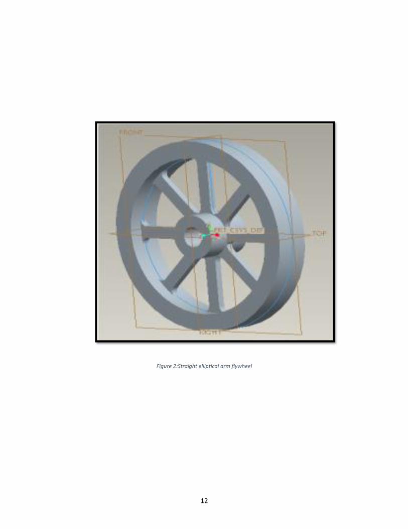
There are many designs of flywheel, the most popular ones are web type flywheel, straight
elliptical arm flywheel, and tapper arm flywheel. For the purpose of this project, all the three
designs are modeled here. The flywheel design is shown below:

11
Figure 1:Web type flywheel
12
Figure 2:Straight elliptical arm flywheel

13
Figure 3:Tapper arm flywheel
The optimal flywheel design will be a flywheel having minimum weight, to provide a particular
moment of inertia and to control the fluctuating energy with safe stresses in all parts of the
flywheel. An optimum design of flywheel is the one that has more inertia and can handle
fluctuations in energy of the shaft. The moment of inertia of a rim is more than that of a disc of
the same mass as the mass is distributed farther away from the center in a rim. Hence a rim is
preferred over a disc for a flywheel.

14
Chapter V
Parametric design of flywheel
Now after all the calculations and modeling is done. The final step is the parametric design
of the flywheel. Here, the excel sheet containing all the parameters is linked with the CREO 7.0
application with the help of Creo Behavioral Modeling Extension (BMX). BMX is the ultimate in
feature based parametric modeling through which a new feature is created that ensure changes to
geometry and update the rest of the model [9]. The pictorial representation of this is shown below.
Figure 4: A representative screenshot of excel spreadsheet with list of parameters to be inputted by the user, and the Output values.
The figure4 above shows all the parameters involved in this design process. For a flywheel design,
the main parameters are, diameter of flywheel and flywheel hole. These two parameters need to
be changed based on the requirement of the press. Before the use of the BMX feature of CREO,
16
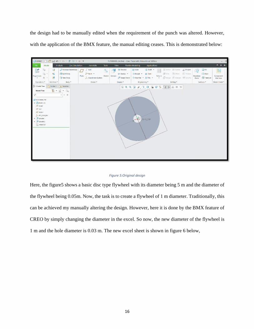
the design had to be manually edited when the requirement of the punch was altered. However,
with the application of the BMX feature, the manual editing ceases. This is demonstrated below:
Figure 5:Original design
Here, the figure5 shows a basic disc type flywheel with its diameter being 5 m and the diameter of
the flywheel being 0.05m. Now, the task is to create a flywheel of 1 m diameter. Traditionally, this
can be achieved my manually altering the design. However, here it is done by the BMX feature of
CREO by simply changing the diameter in the excel. So now, the new diameter of the flywheel is
1 m and the hole diameter is 0.03 m. The new excel sheet is shown in figure 6 below,
17
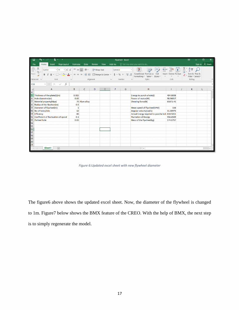
Figure 6:Updated excel sheet with new flywheel diameter
The figure6 above shows the updated excel sheet. Now, the diameter of the flywheel is changed
to 1m. Figure7 below shows the BMX feature of the CREO. With the help of BMX, the next step
is to simply regenerate the model.

18
Figure 7:Regenerating the model by simply pressing a button
Now, this is where the magic happens. By simply hitting regenerate, a new model is drawn with
the provided dimensions. Figure8-9 below demonstrates that,

19
Figure 8:The new model being generated
Figure 9:Updated model with new dimensions

20
Figure 9 above illustrates the new model of the flywheel. It does not quite look like one, but this
was carried out for a demonstration purpose. Hence, a new model was made with just altering the
parameter in the excel sheet and pressing the regenerate button in CREO. This CREO feature has
a huge application. Thousands of hours can be saved by a manufacturing company by simply
automating their design processes. Furthermore, the automation feature is a huge opportunity to
speed up and make the design process dynamic. From re-using design data to create new models
to writing Macros and saving processes to reduce modelling time, the benefit to a company or
design team is huge. Some more benefits of automating the design process are, it helps to capture
and re-use the design knowledge to save time and money, incorporate design rules to minimize
errors and cost from manual mistakes, free design engineers from doing repetitive tasks and
concentrate on new and special designs, and generate variations quickly and easily based on the
rules created [5].

21
Conclusion
The work focused on demonstrating automation of an engineering process as a part of design
of engineering components, using flywheel of a punch press as a representative exampl,.
Traditional design process involved drafting machines and different drafting methods. The
creation of engineering drawings changed very little until after World War II. Patrick Hanratty and
Ivan Sutherland contributed significantly on today’s well-known Computer-aided Design (CAD),
as they consider it as a faster and more accurate tool compared to previous drafting methods. Since
then, more companies began to use CAD software starting around mid-1970s. The computer-aided
design systems began to provide more capability than just an ability to reproduce manual drafting
with electronic drafting, the cost benefit for companies to switch to CAD became apparent [6].
Furthermore, the automation feature is a huge opportunity to speed up and make the design process
dynamic. From re-using design data to create new models to writing Macros and saving processes
to reduce modelling time, the benefit to a company or design team is huge. Some more benefits of
automating the design process are, it helps to capture and re-use the design knowledge to save time
and money, incorporate design rules to minimize errors and cost from manual mistakes, free design
engineers from doing repetitive tasks and concentrate on new and special designs, and generate
variations quickly and easily based on the rules created [10].
Here, a successful demonstration of the automation is shown with the design of flywheel by using
the BMX extension feature of CREO. The flywheel designed with CREO was modified by simply
altering the parameters in the excel sheet. This CREO feature has a huge application. Thousands
22
of hours can be saved by a manufacturing company by simply automating their design processes.
By automating time-sensitive and often repetitive upfront activities, the company will reap the
benefits. The company have more time to innovate and add value to their products, improving their
position in the market. One survey indicated that the typical company re-creates an item’s
geometry five or more times in such areas as customer proposals or marketing specifications;
conceptual design; detail design; finite element analysis; other engineering analysis; detail
drafting; fabrication or assembly sketches; work cell device programming; tooling and fixture
design; and training and service manuals. Each time part geometry or product design information
is independently maintained in a separate system or independently created on paper, another source
of redundant design information is created that needs to be managed [11]. Hence, automation is a
huge opportunity to speed up and make the design process dynamic.
24
References
[1] “Punch Press.” Encyclopædia Britannica, Encyclopædia Britannica, Inc.,
www.britannica.com/technology/punch-press.
[2] B. S. Prathap, and R. Srinivasulu, “Design and Analysis of Flywheel for a Punching
Machine Operation,” in International Journal of Research in Engineering, Science and
Management, vol. 3, no. 1, pp. 237-240, January 2020.
[3] DriveWorks. “What Is Design Automation?” DriveWorks, 27 Jan. 2020,
www.driveworks.co.uk/blog/what-is-design-automation/.
[4] “Design Automation Requirements to Support Product Development.” Npdsolutions,
www.npd-
solutions.com/designauto.html#:~:text=Integrated%20design%20and%20manufacturing%20
automation,activities%20with%20the%20production%20process.
[5] “Why Design Automation Is Important.” CCSL SOLIDWORKS Reseller, 9 Mar. 2019,
www.ccsl-cad.co.uk/why-design-automation-is-important/.
[6] Paro Designs. “The History of Engineering Design • Paro Designs.” Paro Designs, Paro
Designs, 16 Apr. 2020, parodesigns.com/the-history-of-engineering-design/.
[7] “Creo Parametric: An Overview of PTC's CAD/CAE Software.” Fastway Engineering, 15
May 2018, fastwayengineering.com/creo-parametric/.

24
[8] About Jessica Magelssen Jessica Magelssen has contributed 58 entries to our website. “What
Is Creo?” EAC, 13 Nov. 2019, eacpds.com/what-is-creo/.
[9] “Creo Behavioral Modeling Extension (BMX).” Adroitecengg.com, 15 Oct. 2018,
adroitecengg.com/creo-behavioral-modeling-extension-.
[10] “Parametric Design.” Parametric Design - an Overview | ScienceDirect Topics,
www.sciencedirect.com/topics/engineering/parametric-design.
[11] Marco Micheletti Automation Director, and Marco Micheletti. “Principles of Design for
Automated Manufacturing.” Fresh Consulting, 15 May 2020,
www.freshconsulting.com/principles-of-design-for-automated-manufacturing.