Embed Size (px)
Citation preview

Design and Manufacture of a Pick-and-
Place Manipulator for Integration within an
Autonomous Underwater Vehicle
Submitted by Tan Hui Juan Esther (A0100874L)
Department of Mechanical Engineering
In partial fulfillment of the requirements for the Degree of Bachelor of
Engineering
National University of Singapore
Session 2015/2016

i
Summary
Underwater manipulation systems make it possible to access and perform mechanical works
in hostile and hazardous environments where humans cannot enter, such as the deep oceans,
icy waters, natural disaster region or a man-made wreckage. They are highly sought after in
industries ranging from the Oil and Gas Industry to Search and Recovery, Deep water
Archaeology and Marine Science, where they are required to perform tasks such as welding,
valve turning and connector plugging, retrieval of fragile corals or recovery of free-floating
objects (Ridao, Carreras, Ribas, Sanz, & Oliver, n.d.).
These manipulation systems are typically installed on board an underwater vehicle, notably a
Remotely Operated Vehicle (ROV) where tasks are mainly performed under human
supervision, or an Autonomous Underwater Vehicle (AUV) where tasks are performed
independently of human control. Today’s manipulator systems swings between the extremes
of being either too heavy and expensive (Cooney, 2006), or too simple and lacking in
functionalities. Also, the multi-purpose usage of manipulators in various facets demands for a
robust and versatile gripping system.
Henceforth, this project will be on the research, design and fabrication of a manipulator,
which serves a dual role of meeting the industry needs in manipulation systems and also for
competitive use on the Bumblebee Autonomous Underwater Vehicle (AUV). In this thesis,
the mechanical design and integration of a manipulator is presented, with versatile gripping
achieved using a Jamming Gripper technique and precise positioning achieved via pneumatic
actuations and high torque servo rotation.

ii
Acknowledgements
I would like to extend my heartfelt appreciation and gratitude to the following people who have made this FYP
possible:
Firstly I would like to give my glory and thanks to God, my Lord Jesus Christ, in whom all things are made
possible, who is ever-present in good times and bad times, who delivers me from troubles and difficulties, who
has been my source of comfort, strength and wisdom;
Next, my supervisor, Professor Marcelo Ang, first for supporting this self‐initiated project, then for providing
valuable advice and support throughout this journey which has really taught me a lot and provided me the hands-
on exposure I desired as an engineer;
Thank you to Festo for sponsoring the Pneumatic Accessories, Cititech for Laser-Cut Parts and Industrial
partners for their words of advice and encouragement – Wan Chern from Festo, Versaball CTO John Amend;
Thank you Lab Techs from Control Lab – Mrs Ooi, Mdm Hamidah Mr Sakthi, & from FSC – Dickson, Mr Tan;
My Bumblebee teammates who made this project possible, esp Grace, KeeYeow, EngWei, AlexJohn, Steven,
AlexFoo, QiXiang, Vanessa, ShihChiang, JunJie, Jin. I can never thank you enough for your support, guidance,
advice & help with diving. JiaMing, RenJie, Ruth for helping me along the way with ideas on servo management
or video-taking. Big thanks to Ren Zhi, who took up the design of the electrical architecture of the arm, for not
giving up, for your jovial nature and for your companionship over those late nights or long weekends in lab;
My wonderful CG who prayed for my projects, consisting of JinZaw, Emily, Beatrice, Rachel, Elissa, Faye,
Angeline, Audrey, Dora, Wesley, Joshua, Nigel, and Eleanor the ex-neighbour’s neigbour for praying too;
My fellow aunties Amanda, Pei Ying, Audrey – the people who made me look forward to coming to school;
Awesome Friends who have prayed for me or offered a kind word along the way;
Last but not the least, my dear family - Dad, Mum, Dajie, Erjie for your love, care, prayers, encouragement,
patience, and support. For being a huge part of my life. Thank you.

iii
Table of Contents
Summary ...................................................................................................................................... i
Acknowledgements .................................................................................................................... ii
Table of Contents ...................................................................................................................... iii
List of Figures ............................................................................................................................ vi
List of Tables ........................................................................................................................... xiii
1. Introduction ......................................................................................................................... 1
1.1. Objectives .................................................................................................................... 1
1.2. Problem Statement ....................................................................................................... 1
1.3. Scope ............................................................................................................................ 3
1.3.1. Design Constraints ................................................................................................ 3
1.3.2. Competition Manipulator Tasks ........................................................................... 5
2. Literature Survey ................................................................................................................. 6
2.1. Manipulator Arm Types ............................................................................................... 6
2.2. End-effector Types ...................................................................................................... 6
2.2.1. Universal Jamming gripper technique using granular material ............................ 7
3. Mechanical Design of End-effector .................................................................................. 12
3.1. Components of the Jamming Gripper ........................................................................ 12
3.2. Pre-experiment ........................................................................................................... 12
3.3. End-effector Design ................................................................................................... 16

iv
3.3.1. End-effector Design 1 ......................................................................................... 16
3.3.2. End-effector Design 2 ......................................................................................... 19
3.4. Fabrication and Testing ............................................................................................. 21
3.4.1. Testing in Air ...................................................................................................... 22
3.4.2. Testing in Water ................................................................................................. 24
4. Mechanical Design of Manipulator Arm .......................................................................... 26
4.1. Design 1 ..................................................................................................................... 26
4.1.1. Limitations of Design 1 ...................................................................................... 29
4.2. Design 2 ..................................................................................................................... 30
4.2.1. Enhancements to Design 2 ................................................................................. 31
4.2.2. Limitations of Design 2.5 ................................................................................... 33
4.3. Design 3 ..................................................................................................................... 34
4.3.1. Finite Element Analysis (FEA) .......................................................................... 41
4.3.2. Computational Fluid Dynamics (CFD) .............................................................. 45
5. Electrical Architecture of Manipulator ............................................................................. 50
6. Assembly and Testing of Manipulator .............................................................................. 51
6.1. Testing in Air ............................................................................................................. 51
6.2. Testing in water ......................................................................................................... 52
7. Results and Discussions .................................................................................................... 53
8. Conclusions ....................................................................................................................... 55

v
9. Recommendations for Future Works ................................................................................ 56
Appendices ............................................................................................................................... 57
Appendix 2 ............................................................................................................................ 58
References ................................................................................................................................ 77

vi
List of Figures
Figure 1: Bumblebee Autonomous Underwater Vehicle Version 3.0 ........................................ 1
Figure 2: Industry Underwater Manipulators; Left - Schilling Robotics TITAN 4 (FMC
Technologies, 2015), Right- Seabotix Grabber on Remotely Operated Vehicle (Seabotix,
2015) ........................................................................................................................................... 2
Figure 3: 3D CAD of Manipulator Design for Bumblebee AUV Version 2.5 ........................... 2
Figure 4: CAD of Available Mounting Space for Manipulator on Bumblebee AUV marked by
red box ........................................................................................................................................ 4
Figure 5: Left - Lack of available space at the Bottom due to the Doppler Velocity Log
Sensor, Right -Lack of available space at the Front due to occupancy by the Front Camera,
Sonar, and Yaw Thrusters .......................................................................................................... 4
Figure 6: Examples of Manipulation Tasks at the AUV Competitions ...................................... 5
Figure 7: Empire Robotics’ VERSABALL Gripper Conforming to Shape and Lifting Objects;
Left - Hammer, Right - Brick, (Empire Robotics, 2016) ........................................................... 7
Figure 8: Granular interaction in unjammed (fluid-like) and jammed (solid-like) states
(Mozeika, 2015) ......................................................................................................................... 8
Figure 9: Contact Networks in the Modeled System; Left - Unjammed state (Packing = 89%)
, Right - Jammed state (Packing = 90.5%) state. For each grain, i, a line is drawn from its
center to the neighboring grain (Herman, 2013) ........................................................................ 9
Figure 10: Left - Features of the Vacuum generator, Right - Bernoulli’s Equation
(Hyperphysics, 2015) ................................................................................................................. 9

vii
Figure 11: Three gripping modes of Jamming Grippers, Left -Static friction from surface
contact, Centre - Geometric constraints from interlocking, Right - Vacuum suction from
airtight seal, (Amend et al, 2012) ............................................................................................. 11
Figure 12: Jamming Gripper Mini Experimental Set-up .......................................................... 13
Figure 13: Left - Fine Grain Coffee enables relatively higher object conformation, Centre –
Coarse coffee enables relatively lower object conformation, Right – Fine & Coarse Grain Mix
enables relatively higher object conformation.......................................................................... 14
Figure 14: Left – Fine Grain Coffee leaving relatively Less Defined Imprint on membrane,
Centre - Coarse Grain Coffee leaving relatively More Defined Imprint on membrane, Right –
Fine & Coarse Grain Mix leaving relatively More Defined Imprint on membrane ................. 15
Figure 15: Gripper Collar assembly consisting of cup and throat ............................................ 16
Figure 16: 3-D printed prototypes of Gripping cups - Deep cup versus Shallow wide cup ..... 17
Figure 17: Assembly of End-effector ....................................................................................... 17
Figure 18: Left - Vacuum Pump is connected to the 24” gripper via Custom-made adaptor,
Centre - Jamming Gripper is successful in picking up the oval metal structure, Right -
Jamming Gripper is successful in picking up the K’nex .......................................................... 18
Figure 19: Partially Exploded CAD View of Pneumatic Housing ........................................... 18
Figure 20: Left - Isometric CAD View of the Vacuum Generator Mount, Right - CAD
Assembly of the Vacuum Generator inside the Pneumatic Hull .............................................. 19
Figure 21: Left - Cross-sectional CAD of End-effector Design 2; Right - Water Entry Points
of End-effector .......................................................................................................................... 20
Figure 22: CAD Diagram of Gripper Lid Support ................................................................... 20

viii
Figure 23: Left - 3-D Printed ABS Prototype of Design 2 End-Effector, Right - End-effector
Assembly comprising 3D printed Gripping Collar, Latex Balloon, Coffee Powder and Filter
Paper ......................................................................................................................................... 21
Figure 24: Left - End-effector lifting up a PVC pipe structure of weight 475g, Right - Weight
of PVC pipe structure ............................................................................................................... 21
Figure 25: Left - Gripper Collar, Right - Gripper Lid .............................................................. 22
Figure 26: Setup of Jamming Gripper Experiment in Air ........................................................ 22
Figure 27: 100% gripping success case, Left – Gripper contacts ground (Flat underneath),
Right - ¾ or more wrap-around Diameter ................................................................................ 23
Figure 28: 80% Gripping Success Case from Geometric Interlocking with ½ or less wrap-
around Diameter ....................................................................................................................... 23
Figure 29: 20% gripping success case, Left– Gripper does not contact ground (Round
underneath), Right - ½ or less wrap-around Diameter ............................................................. 24
Figure 30: Experimental Setup for testing Jamming Gripper in Water .................................... 25
Figure 31: Irregular Object Conformability of Jamming Gripper of a smaller, less packed
membrane ................................................................................................................................. 25
Figure 32: Successful Gripping using Jamming Gripper of larger, more highly packed
membrane ................................................................................................................................. 26
Figure 33: CAD model of Manipulator Design in a Keeping Position .................................... 28
Figure 34: Left - CFFAP6-16 Cam Follower (Misumi, 2016), Right - Cross-section of a cam
follower (Ikont.co.jp, 2016) ...................................................................................................... 28
Figure 35: Servocity Flanged shaft hub (Servocity.com, 2016) ............................................... 28

ix
Figure 36: Manipulator Configurations - Keeping, Forward, Scooping, Picking, Downward
positions .................................................................................................................................... 29
Figure 37: Manipulator Configurations on AUV- Keeping, Forward, Scooping, Picking,
Downward ................................................................................................................................ 29
Figure 38: CAD model of Manipulator Design in a Forward Extend Position ........................ 31
Figure 39: Manipulator Configurations on AUV- Forward, Downward and Keeping Positions
.................................................................................................................................................. 31
Figure 40: Working Principle of Festo Semi-Rotary Pneumatic Actuator (Festo, 2015) ........ 32
Figure 41: CAD model of Enhanced Manipulator Design 2.5 in a Forward Extend Position . 32
Figure 42: Manipulator Configurations mounted on AUV- Forward, Downward and Keeping
Positions ................................................................................................................................... 33
Figure 43: Non-uniform Diameter in Guide Rod Passages within Linear Actuator ................ 33
Figure 44: CAD model of Manipulator Design 3 in a Forward Retracted Position ................. 34
Figure 45: Manipulator Configurations mounted on AUV- Forward, Downward and Keeping
Positions ................................................................................................................................... 35
Figure 46: Gear Relationship (DesignAerospace, 2016) .......................................................... 35
Figure 47: Left - Optek Slotted Optocoupler (RS Components, 2016), Right - Basic Limit
Switch (Omron, 2016) .............................................................................................................. 36
Figure 48: CAD Model of Optopcoupler Mount and Limit Switch Mount ............................. 37
Figure 49: Servo Setup with a 5:1 Gear Ratio to Step Up the Torque ..................................... 37
Figure 50: CAD model of Servo Housing ................................................................................ 38
Figure 51: CAD model of Servo Housing Lid and Rotary Seal Cap ....................................... 39
Figure 52: Field of View of a Camera (longrangecamera.com, 2015) ..................................... 40

x
Figure 53: Top - CAD of Forward Manipulator Position within the FOV of the Front Camera,
Centre - Forward Manipulator Position within the FOV of the Front Camera, Bottom -
Minimum Clearance from DVL to the Seafloor ....................................................................... 40
Figure 54: CAD model of T-slot Guide Rod on Linear Actuator ............................................ 41
Figure 55: Left - Applied Forces on Servo housing, Right - Meshed Servo Housing ............. 42
Figure 56: Servo Housing Static Stress Plot ............................................................................. 42
Figure 57: Servo Housing Resultant Displacement Plot .......................................................... 42
Figure 58: Left - Applied Forces and Torque on Link 1, Right - Meshed Link 1 .................... 43
Figure 59: Link 1 Static Stress Plot .......................................................................................... 43
Figure 60: Link 1 Resultant Displacement Plot........................................................................ 44
Figure 61: Forces applied on Shaft ........................................................................................... 44
Figure 62: Shaft Static Stress Plot ............................................................................................ 44
Figure 63: Shaft Resultant Displacement Plot .......................................................................... 45
Figure 64: Flow Simulation Results for Currents Flow of 1.5 m/s .......................................... 46
Figure 65: CFD Results For Manipulator in Bottom-Facing Position ..................................... 47
Figure 66: Pressure Simulation Results for Currents Flow of 1.5 m/s ..................................... 47
Figure 67: Flow Simulation Results for Forward AUV Motion of 1.5 m/s ............................. 48
Figure 68: CFD Results For Manipulator in Keeping Position ................................................ 48
Figure 69: Flow Simulation Results for Forward Actuation Motion in Back Currents of 1.5
m/s ............................................................................................................................................ 49
Figure 70: CFD Results of Manipulator in a Forward Position ............................................... 49
Figure 71: Left -Schematic Diagram of the Electrical Architecture for the Manipulator
System, Right - Fabricated Manipulator Printed Circuit Board ............................................... 50

xi
Figure 72: Assembly of Servo Components ............................................................................. 51
Figure 73: Assembly of Manipulator........................................................................................ 51
Figure 74: Air Trials Results , Left – 45° Configuration, Right – 135° Configuration ............ 52
Appendix 1 – Figure 75: Official Competition Rules for SAUVC 2016 and Robosub 2016 .. 57
Figure 76: Different grades of Coffee grains, with increasing coarseness from 1 to 4 ............ 63
Figure 77: Left - Fine Grain Coffee used to pick up a tweezer by the tip, Right - Coarse Grain
Coffee used to pick up a tweezer by the tip .............................................................................. 64
Figure 78: Left - Fine Grain Coffee used to pick up a tweezer by the flat side, Right - Mixture
of Fine & Coarse Grain Coffee used to pick up a tweezer by the flat side .............................. 65
Figure 79: Left - Fine Grain Coffee used to pick up a pen by the cylindrical end, Centre -
Coarse Grain Coffee used to pick up a pen by the cylindrical end, Right - Fine Grain Coffee
used to pick up a pen from a bucket of water by the cylindrical end ....................................... 65
Figure 80: Left - Fine Grain Coffee used to pick up a watch, Centre - Coarse Grain Coffee
used to pick up a watch, Right - A mixture of Fine & Coarse Grain Coffee used to pick up a
watch ......................................................................................................................................... 65
Figure 81: Gripping of Various Objects in air trials; First row (from left) – K’nex structure,
Optical Mouse, 25mm cylindrical light PVC pipe; Second Row (from left) – 32mm cylindrical
PVC pipe, T-junction PVC pipe, 43mm cylindrical light PVC pipe; Third Row(from left) -
25mm cylindrical heavy PVC pipe, cuboid power bank, 43mm cylindrical heavy PVC pipe 72
Figure 82: HS-7950TH Servo Specifications (Servocity, 2016) .............................................. 73
Figure 83: CAD Model of Manipulator Arm ........................................................................... 73
Figure 84: Gripping of Various Objects in air trials; First row (from left) – 25mm PVC Pipe,
43mm PVC Pipe, K’nex Structure, Second Row (from Left): U channel, Odd Geometric

xii
Structure, Square tube, Sphere ,Third Row (from left): 2 Pearl Weight, Screwdriver Head,
Kick Board ................................................................................................................................ 76

xiii
List of Tables
Table 1: Characteristics, Advantages and Disadvantages of Manipulator Types (Kuttan, 2007)
& (Circuitdigest.com, 2015) ..................................................................................................... 58
Table 2: Characteristics, Advantages and Disadvantages of Different Actuation Types ......... 59
Table 3: Density of Common Granular Materials (Engineering toolbox, 2015) ...................... 63
Table 4: Tabulation of Pre-Experiment Results of 5” Jamming Gripper ................................. 64
Table 5: Tabulation of Results of Gripping Various Weights using a 24” Jamming Gripper . 71
Table 6: Tabulation of Stepped-Up Servo HS-7950TH Characteristics .................................. 74

1
1. Introduction
1.1. Objectives
The objective of this project is to design and manufacture a robust, low cost manipulator to be
used on board an Autonomous Underwater Vehicle (AUV). It will be customized to fit the
Bumblebee AUV Version 3.0, an AUV designed and built by NUS students, where it will be
integrated, operated and evaluated for its effectiveness.
Figure 1: Bumblebee Autonomous Underwater Vehicle Version 3.0
1.2. Problem Statement
Underwater robotic arm technologies can either be very expensive or possess limited
functionality (Cooney, 2006). Robotic arms with multiple degrees of freedom are typically
designed for larger vehicles and higher depth rating, but are often expensive and heavy. An
example is Schilling Robotics’ Titan (Fig 2, left) which is dexterous and robust, but it is
pricey and weighs up to 100 kg in air (FMC Technologies, 2015). In contrast, lower cost
manipulators for instance, the three jawed Seabotix manipulators (Fig 2, right), (Seabotix,
2015), commonly have limited applications and capabilities, placing a greater dependence on
vehicle maneuverability in order to achieve complex manipulator tasks.

2
Figure 2: Industry Underwater Manipulators; Left - Schilling Robotics TITAN 4 (FMC Technologies, 2015), Right-
Seabotix Grabber on Remotely Operated Vehicle (Seabotix, 2015)
Furthermore, a motivation for this project is due to several limitations of the existing
manipulator design on Bumblebee AUV Version 2.5:
Figure 3: 3D CAD of Manipulator Design for Bumblebee AUV Version 2.5
1) Low Versatility - Manipulator design is specific to item being grabbed, requiring
change in shape of manipulator every year according to competition tasks.
2) Need for Accurate Positioning – When grabbing objects, there is a high reliance on
proper positioning of the vehicle and grabber, resulting in a low success rate
3) Limited Capabilities - Grabber claws can only open and close. It is also installed at the
bottom of the vehicle and is unable to do forward facing tasks.

3
4) Need for Redundancy: 2 sets of grabbers required for more stable grasp on larger
objects, without which objects will dangle and sway.
5) Close Proximity required: When grabbing objects from the ground, vehicle has to go
very closely to the object. This covers the bottom facing camera and prevents it from
focusing on the object to pick up. Also, it causes a problem in the DVL sensor when
minimum distance from the sensor to the sea floor <50cm.
6) Prone to damage: 3-D printed Claws are easily broken off when vehicle is placed on
the floor with closed grabbers because it protrudes out of vehicle.
1.3. Scope
The focus of this project is to design for functionality and system integration onto an existing
AUV, which will be used to compete in the Singapore Autonomous Underwater Vehicle
Challenge (SAUVC) organized by IEEE, and the 19th Annual International Robosub
Competition organized by AUVSI Foundation. Following design, the manipulator arm will be
fabricated, and in-depth experimentation will be performed to test out the effectiveness of the
design. Besides being reliable, it is essential that the system stays within the design constraints
imposed by competition rules and also within the requirements of the sensors on the AUV.
1.3.1. Design Constraints
For proper integration of the manipulator to the main vehicle, the manipulator must adhere to
the following characteristics:
1) Compact Size & Lightweight
The AUV must comply with competition specifications (Appendix 1) – which impose an
upper limit of 50kg and 140x91x91(cm) in dimensions, otherwise there will be points

4
deduction or disqualification from the competition. Hence, an arm that is light and able to be
folded for keeping is advantageous in reducing the overall weight and length of the AUV.
Moreover, a compact arm will encounter less drag force which improves manipulation
performance.
2) Positioning
The available space on the AUV to mount the manipulator is the area marked in red (Fig 4).
The form and type of arm that can be used is limited by the occupancy of various sensors and
thrusters which the arm needs to steer clear of, as shown in Figure 5.
Figure 4: CAD of Available Mounting Space for Manipulator on Bumblebee AUV marked by red box
Figure 5: Left - Lack of available space at the Bottom due to the Doppler Velocity Log Sensor, Right -Lack of
available space at the Front due to occupancy by the Front Camera, Sonar, and Yaw Thrusters
3) Pressurised gas

5
The rules (Appendix 1) capped the compressed gas pressure to be 6 bars, and the current
portable compressed air tank on the vehicle has a capacity of 13 cu in, so the usage of any
pneumatic components must keep within these specified limits.
4) Maximum power voltage
The rules (Appendix 1) capped the maximum power voltage to be 24V DC, so the usage of
any electrical components e.g. motors and regulators should keep within these requirements.
1.3.2. Competition Manipulator Tasks
The manipulation tasks varies across the years, and they included - turning a steering wheel,
lifting and sliding a handle off a board, and picking and placing of different objects such as
PVC pipe structures or K’nex structure etc (Fig 6).
Figure 6: Examples of Manipulation Tasks at the AUV Competitions

6
2. Literature Survey
Literature research was carried out to generate design ideas on how the manipulator and
gripper should be developed.
2.1. Manipulator Arm Types
The body structure of a manipulator determines the functions, reach, orientation and the
overall workspace. Also, the joint types used to connect different members of the manipulator
determine the overall degrees of freedom of the manipulator in motion (Brighthub
Engineering, 2015).
There are many types of industrial manipulators and the type is selected depending on its pros
and cons as well as the application requirements. Table 1 (Appendix 2) displays the common
types of arms used in the industry into 5 categories - Cartesian, Cylindrical, Polar, SCARA
and PUMA. The study of the various types influenced the design process of the manipulator
arm which will be covered in Section 4.
2.2. End-effector Types
The end-effector, commonly known as a gripper, is crucial because it is the mechanical
interface between the robot and the work environment (D.T. Pham and S.H. Yeo, 1988). It
facilitates temporary contact with the manipulated object, ensuring its position and orientation
during transport and specific activities. There are many different types of gripper mechanisms,
which Nair (2009) classifies into 3 categories:
1) Mechanical Finger Grippers (Sub-classification is based on actuation method)
2) Vacuum and Magnetic Grippers (Sub-classification is based on type of the force-
exerting elements)

7
3) Universal Grippers (Sub-classification is inflatable fingers, soft fingers & three
fingered grippers)
In terms of actuation, there are generally five types- Pneumatic, Hydraulic, DC Motors, AC
Motors and Vacuum actuation. Table 2 (Appendix 3) categorises the various types of
actuations, their characteristics and applications, as well as the pros and cons associated with
their usage. Additionally, research was carried out on a unconventional technique which
combines pneumatic and vacuum actuation, known as the Universal Jamming Gripper
technique.
2.2.1. Universal Jamming gripper technique using granular material
The Universal Jamming Gripper consists of a mass of granular material encased in non-porous
elastic membrane (Brown et al., 2010). Through a combination of positive and negative
pressure, the gripper can rapidly grip and release a wide range of objects. In Fig 7, the gripper
passively conforms to the shape of a target object, and when a negative pressure (vacuum) is
applied, the granular materials become stiff, achieving a rigid grip. Positive pressure is then
utilized to reverse this transition—releasing the object and returning to a deformable state.
Figure 7: Empire Robotics’ VERSABALL Gripper Conforming to Shape and Lifting Objects; Left - Hammer, Right
- Brick, (Empire Robotics, 2016)

8
Granular Behaviour and Properties
Granular material exhibit both fluid-like and solid-like states (Fig 8). Naturally they exist in
fluid-like state, where excess interstitial fluid (typically air) is enclosed with the loosely-
packed particles and they flow freely when subjected to external forces. Hence, when pressed
on an object, the particles surrounds and takes the shape of the object it is grasping.
Meanwhile when a vacuum is created to remove the interstitial fluid, the flexible membrane in
an attempt to equalize the pressure constricts the particles, causing them to shift and fill up the
voids left behind by the evacuated fluid, e.g. Air. Thus, the packing factor and the contact
networks between the particles increases (Fig 9), and they become solid-like (Mozeika, 2016).
This is known as jamming, where granular materials exhibit a yield stress such that forces can
be distributed through groups of particles and as a whole it can function as a compliant or stiff
material (Follmer, Leithinger, Olwal, Cheng, & Ishii, 2012).
Figure 8: Granular interaction in unjammed (fluid-like) and jammed (solid-like) states (Mozeika, 2015)

9
Figure 9: Contact Networks in the Modeled System; Left - Unjammed state (Packing = 89%) , Right - Jammed state
(Packing = 90.5%) state. For each grain, i, a line is drawn from its center to the neighboring grain (Herman, 2013)
Vacuum generator
Evacuation of air can be achieved by the vacuum generator, a lightweight and compact device
that generates a vacuum using the Venturi principle, where the motion of a moving fluid
(motive fluid such as compressed air) is used to transport away another fluid, creating suction
(Fig 10, left). As the tube narrows at the diffuser throat, the velocity of the fluid increases,
Bernoulli’s principle (Fig 10, right) states that there will be a resulting proportionate decrease
in pressure in order to maintain the same total mechanical energy (= Potential Energy +
Kinetic Energy + Pressure Head). As air moves from a location of high pressure to low
pressure, the low pressure region in the diffuser causes air to rush in through the suction port,
generating a vacuum. The commonly used vacuum units is Torrs (mmHg).
Figure 10: Left - Features of the Vacuum generator, Right - Bernoulli’s Equation (Hyperphysics, 2015)

10
Gripping Mechanism
This gripper leverages three possible gripping modes for operation as can be seen from Fig 11:
1) static friction from surface contact; 2) geometric constraints from capture of the object by
interlocking; and 3) vacuum suction when an airtight seal is achieved on a portion of the
object’s surface. The friction force results from the slight (<0.5%) volume contraction of the
membrane that occurs during evacuation, which, in turn, causes a pinch force to develop,
normal to the point of contact. Slip can be prevented either by friction from contact pressure
or by exploiting geometric constraints, for example by wrapping around protrusions. By
achieving one or more of these three gripping modes, the jamming gripper can grip many
different objects with diverse shapes, weights, and fragility, including objects that are
traditionally challenging for other universal grippers (Amend et. al., 2012).
The key parameter that determines the gripping strength is the holding force Fh. A set of
equations derived by Brown et. al. (2010) through experimentation on test spheres of varying
radius R can be used to describe contributions to holding force Fh for the three gripping modes
(Appendix 4). In summary, Brown’s results demonstrated that the holding force Fh is mainly
dependent on friction and suction mechanisms, which builds up when the contracting
membrane compresses against the object to be gripped; meanwhile contributions from
geometric interlocking depends on the extent of interlocking and can involve the full stress-
strain curve. Other secondary parameters that are directly proportional to the gripping strength
are: the properties of the granular material in jammed state (i.e. the size, shape and surface
roughness which affects granular strength and rigidity), the confining pressure induced by the
vacuum, hardness of the objects being grabbed, surface contact angle of the gripper-object
interface and membrane elasticity (Brown et. al., 2010).

11
Figure 11: Three gripping modes of Jamming Grippers, Left -Static friction from surface contact, Centre - Geometric
constraints from interlocking, Right - Vacuum suction from airtight seal, (Amend et al, 2012)
Granular jamming gripping technique as the End-effector Choice
The jamming gripper is advantageous as it can grab a wide variety of arbitrarily shaped
objects. Also, it eliminates the computational complexities presented by active grippers,
notably the multi-fingered arms within dependently actuated joints. Moreover, the gripper
possesses high reliability, error tolerance, and placement accuracy (Amend, Brown,
Rodenberg, Jaeger, & Lipson, 2012). Given the competition constraints and task requirements,
these factors make it suitable for application on the Bumblebee AUV.
In this project, its potential usage in the underwater realm will be explored, where the
increasing pressure with depth may aid in enhancing the gripping force. Also, experimentation
will be conducted on various types of objects before conducting evaluation on the gripper
performance, as previous test experiments conducted by researchers made used of spheres as
target objects which may not be sufficient. Additionally, design aspects will be improved to
optimize the gripping capabilities. Hence, this universal jamming technique will be adapted
and the design modified to suit underwater usage and installation onto the Bumblebee AUV.

12
3. Mechanical Design of End-effector
To enable robust gripping capabilities, recommendations from literature research were used to
identify the most suitable components and materials required to build the jamming
manipulator, and datasheets of these components were thoroughly read before procurement.
3.1. Components of the Jamming Gripper
The choice of granular material, Coffee powder, was due to its lowest density amongst
common granular materials (Appendix 5). Several grades of coffee powder ranging in
coarseness were selected as granular material to be pre-tested (in section 3.2), to identify the
ideal granular size for gripping. This is because Brown (2010) suggested that small grain sizes
is advantageous as it increases the degree of conformation, but not too small as the gas
permeability of a powder scales with the square of the grain diameter; hence, decreasing grain
diameter increases the pumping time required to reach a strongly jammed state.
Meanwhile, considerations for the membrane include flexibility for better conformation,
impermeability to allow for pressure build up during jamming, and a coefficient of friction
μ≈1 for friction or suction to work at small contact angles. Hence, a standard size 5” Natural
Rubber balloon was used as the elastic membrane.
3.2. Pre-experiment
Initially, a simple experiment was carried out to test the feasibility of the jamming technique
and to gain an understanding of the control variables and how they affect the experiment. To
create a vacuum required for granular jamming, a syringe was used (Fig 12, left). However,
the sealing using a tape was ineffective and a near-vacuum condition cannot be created,
resulting in the inability to harden the grains. The syringe was subsequently replaced by a

13
soap dispenser of a diameter slightly larger than balloon mouth to create an effective seal (Fig
12, right), and air can be constantly expelled out thus generating near-vacuum conditions.
Figure 12: Jamming Gripper Mini Experimental Set-up
Objects of varying shape and weight were lifted, and tested in air and in a small bucket of
water (water column height = 100 mm, external pressure ~ 0.01 bar). Trials were performed
on fine grains, coarse grains and a mixture of both grains (amount of each weighs ½ of the
total weight). Trials were repeated 3 times, and the more common result taken to be recorded
in Table 4 (Appendix 6).
Several observations are made from the experiment:
1) High success rate of picking up objects smaller than the membrane diameter and
objects wrapped around >75% by the membrane (3 out of 4 object faces in contact
with the membrane).
2) Possibility for the grains to pick up objects exceeding its weight by 8 times
3) The experiments in water tend to fail more than on air because of slip due to reduced
friction between object and walls of the membrane
4) For fine grain material, it is relatively more successful in picking up objects with
complex geometries.

14
This is supported by Herman (2013), who asserted that fine particles act as “fillers” in the
empty spaces between coarser grain particles, which flows more easily to fill up the voids
created by the object geometry, resulting in a greater conformation to the object shape and a
more secure grip. This is observed when comparing Fig 13 left and centre images. Also, as
seen in Fig 13 (right), combining both fine and coarse grains in the membrane gave a similar
outcome as the sole use of fine grains.
Figure 13: Left - Fine Grain Coffee enables relatively higher object conformation, Centre – Coarse coffee enables
relatively lower object conformation, Right – Fine & Coarse Grain Mix enables relatively higher object conformation
5) For coarse grain materials, it reduces slipping tendencies and is more able to pick up
objects with less contact points, i.e. flatter objects.
As seen from Fig 14, after the removal of the objects, the membrane remains deeply etched
by the object for coarse grain materials (centre) as compared to the fine grains (left). This is
explained by the higher rigidity of coarse particles, ie. resistance for grains to flow past each
other in vacuum state, thus retaining its form and increasing gripping strength on the object.
Herman (2013) supports this from his statement that it is the coarse particles which forms the
“stable skeleton of the global and force network”. Moreover, Xu and Ching (2010) stated in

15
support that coarse particles are easier than fine particles to jam. Combining both fine and
coarse grains also resulted in a similar outcome from solely using coarse grains (Fig 14, right).
6) The combination of both fine and coarse grain materials encompasses the merits of
each individual grain type.
Figure 14: Left – Fine Grain Coffee leaving relatively Less Defined Imprint on membrane, Centre - Coarse Grain
Coffee leaving relatively More Defined Imprint on membrane, Right – Fine & Coarse Grain Mix leaving relatively
More Defined Imprint on membrane
Based on these observations, it is deduced that a mix of both fine and coarse grains should be
used in the actual prototype, and the balloon membrane has to be sufficiently big to grip the
structures used in the competition. The standard-size 5” balloon was far too small for grabbing
most objects and so it was replaced by a 24” latex balloon. The design of the gripper segment
was affected by these observations and it will be elaborated upon in the subsequent section.

16
3.3. End-effector Design
3.3.1. End-effector Design 1
Figure 15: Gripper Collar assembly consisting of cup and throat
The gripper collar assembly shown in Figure 15 will be made of T6-6061 Aluminium, a light
and relatively corrosion-resistant material, and it is designed as an assembly of two separate
parts – the cup and throat, to simplify the machining process. To seal the collar properly and
prevent water entry into the balloon, there are 2 radial o-ring grooves on the cup, which will
be compressed when the throat is plugged onto it. The throat also contains an outer o-ring
groove meant for face sealing, where the o-ring will be compressed by a lid using 6 bolts. The
inner groove on the throat is designed to be deep and wide to slot in both the balloon and a
filter paper which prevents the suction of grains into the vacuum pump.
A 3D printed prototype was constructed for testing its effectiveness, and it was observed that a
rounded deep cup (Fig 16, left) was relatively inefficient for gripping objects of larger
diameters or lengths in comparison to a shallower but wider cup (Fig 16, right). This is
because enclosing larger objects within the grasp was inhibited by the rim of the deep cup, and
in the process many grains were trapped against the cup walls and unutilized, rather than

17
being made to flow around the object for gripping. Meanwhile, the shallow cup manages to
shape the grains to better surround the object for a more efficient gripping.
Figure 16: 3-D printed prototypes of Gripping cups - Deep cup versus Shallow wide cup
Figure 17: Assembly of End-effector
A series of mini tests were performed on the actual sized prototype, a 24” balloon filled with a
mixture of fine and coarse grains. To achieve a vacuum for the jamming of grains, a vacuum
generator VADMI 45-LS-P sponsored by Festo (Appendix 7) was chosen for its high vacuum
percentage of 85% or 115 Torrs, modularity and air saving circuit. The vacuum generator was
connected to a power source and a gas compressor, generating a suction effect in the balloon.
This was demonstrated on several objects as shown in Fig 18 and gripping was successful.

18
Figure 18: Left - Vacuum Pump is connected to the 24” gripper via Custom-made adaptor, Centre - Jamming Gripper
is successful in picking up the oval metal structure, Right - Jamming Gripper is successful in picking up the K’nex
Being electrically activated, the plan for the vacuum generator is to be located in the
pneumatic hull of the AUV, which currently houses pneumatic components such as the
solenoid valves, manifold rail and pneumatic fittings. The pneumatic hull was chosen to keep
it waterproof and enable it to be conveniently connected to the solenoid valves, which control
the power and air supplied to the pump. Externally, the pneumatics hull comes in three parts:
the front cap; the hull body; and the end cap which holds up the solenoids using a mount for
easy disassembly during maintenance (Fig 19).
Figure 19: Partially Exploded CAD View of Pneumatic Housing

19
As the pneumatic hull was fabricated earlier before the conception of this project, there was
limited space inside for the vacuum generator. Hence, a uniquely shaped 3D printed part
shown in Fig 20 (left) was designed to mount the vacuum generator in an inclined position to
fit into the existing design of the pneumatic hull (Fig 20b).
Figure 20: Left - Isometric CAD View of the Vacuum Generator Mount, Right - CAD Assembly of the Vacuum
Generator inside the Pneumatic Hull
3.3.2. End-effector Design 2
Upon submersion of the prototype in water, the water entry points were better understood (Fig
21, right) -water enters from underneath the cup and though the flange. Moreover, to cut down
costs from having to fabricate separate pieces, the gripper throat and cup components (Fig 17)
were combined to form a single piece design. The enhanced gripper design as shown and
labeled in Fig 21 (left) has a face seal at the top and an internal radial o-ring seal, compressed
respectively by the gripping support and aluminium cap for sealing off water entry. The o-ring
groove dimensions are designed according to recommendations by Parker Hannifin
Corporation (Appendix 9) and the o-rings selected are of standard size.

20
Figure 21: Left - Cross-sectional CAD of End-effector Design 2; Right - Water Entry Points of End-effector
Meanwhile, the lid meant for compressing the face seal o-ring (gripping support) was
designed as shown in Fig 22, with an L-shape hole for air flow away from the membrane to
the vacuum generator during suction via pneumatic tubings, joined by a Festo push-fit
connector, QSML-M5-6 (Appendix 8). It also contains threads to be bolted to the main arm
(consisting of a threaded linear piston) and guide rods for distributed support of gripper
weight, as will be elaborated later in Section 4 – Mechanical Design of the Manipulator Arm.
Figure 22: CAD Diagram of Gripper Lid Support

21
Figure 23: Left - 3-D Printed ABS Prototype of Design 2 End-Effector, Right - End-effector Assembly comprising 3D
printed Gripping Collar, Latex Balloon, Coffee Powder and Filter Paper
A prototype of Design 2 was 3-D printed using ABS plastic filament for a smooth glossy
finish and then assembled (Fig 23). The trial in air was successful in which a balloon filled
with 80g of coffee powder managed to pick up a PVC structure of at least 5 times its weight,
as shown in Fig 24. The setup failed during water trials because water went into the balloon,
arguably because of the unsuitability of 3D printed parts where warping during the printing
process resulted in non-uniformity and some porosity for water to flow through.
Figure 24: Left - End-effector lifting up a PVC pipe structure of weight 475g, Right - Weight of PVC pipe structure
3.4. Fabrication and Testing
With successful trial grabs by the jamming gripper in air, the design was proceeded to be
fabricated in Al T6-6061, a light metal which is easy to machine, has high strength and has
high corrosion-resistance. The fabricated collar and lid are shown in Fig 25, with the lid
corners (Fig 22) filleted to remove excess material and reduce overall weight of the gripper.

22
Figure 25: Left - Gripper Collar, Right - Gripper Lid
3.4.1. Testing in Air
The objective of this trial is to test the reliability of gripping various objects, and identify any
limitations to improve gripping performance. The test setup consists of a 24” balloon 60%-
filled with coarse and fine mix of coffee (105g), a vacuum generator, a power supply and an
air compressor. Objects of diverse shapes, weight and dimensions, including competition-used
objects i.e. PVC pipes were each picked up 10 times and the success rate recorded in Table 5
(Appendix 10). Each trial involved lifting the object and subjecting the gripper to a vigorous
sideways swaying motion to determine if the grip exerted on the object is sufficiently firm.
Figure 26: Setup of Jamming Gripper Experiment in Air

23
The results (Appendix 10) in general show that gripping reliability increases with decreasing
object weights and dimensions. From the differing success rates, the following characteristics
were observed about the gripper:
1) 100% success rate: Gripper contacts the ground and is pressed flat during gripping; at
least ¾ of the object surface is wrapped by the membrane (Fig 27).
Figure 27: 100% gripping success case, Left – Gripper contacts ground (Flat underneath), Right - ¾ or more wrap-
around Diameter
2) 80% success rate: Less than ½ of the object total surface area is wrapped by the
membrane; Object engages in geometric interlocking with membrane due to
complexity of object geometries (Fig 28).
Figure 28: 80% Gripping Success Case from Geometric Interlocking with ½ or less wrap-around Diameter

24
3) 20% success rate: Gripper does not contact the ground; membrane wraps ½ or less of
the object surface area (Fig 28).
Figure 29: 20% gripping success case, Left– Gripper does not contact ground (Round underneath), Right - ½ or less
wrap-around Diameter
From this experiment, it is deduced that it is highly difficult to grasp objects with smooth,
uniformly curved geometries (PVC straight pipe) rather than geometrically complex objects
(PVC T-junction). The reason is that friction is very low for these smooth objects, resulting in
only the suction gripping mode being utilized for the former case, while suction plus
geometric interlocking modes for latter case. For gripping such objects, it is therefore essential
to ensure a sufficiently large granular membrane to surround at least ¾ of the object to
simulate a geometric locking which will enhance reliability. This criterion can be simply
fulfilled by observing that the bottom of the gripper is compressed flat during object gripping.
3.4.2. Testing in Water
The objective of this experiment was to test the waterproof design of the gripper, its ability to
grip objects in underwater conditions and the gripping technique to be used. A similar
experimental setup as in Section 4.1 was put up at Queenstown Swimming Complex’s diving
pool, with the vacuum generator powered by a 24V 3000mAh battery. The gripper turned
solid hard within depth of 2m (0.2 bar pressure) without the need to operate the vacuum

25
generator. To pick up objects, positive pressure had to be input into the gripper to inflate it to
surround the object, before applying a negative vacuum for suction. The successful outcome
of gripping of 25mm pipe when using the 24” balloon as before was low. It was observed to
be more challenging than in air because of the drag force of the water, greatly reduced friction
at the gripper-object interface and the floatability of the low density grains which reduced
conformability around the objects.
Figure 30: Experimental Setup for testing Jamming Gripper in Water
Figure 31: Irregular Object Conformability of Jamming Gripper of a smaller, less packed membrane

26
To achieve a higher reliability of gripping in water, the 60%-filled 24” membrane was
replaced with an 80%-filled 36” membrane (Fig 32) to increase the likelihood of grains
surrounding the object and establishing a firmer grip. This time, gripping was successful
during all the trials. The downside was the increased amount in air required, as it took 14
seconds to inflate and deflate the larger membrane for grabbing.
Figure 32: Successful Gripping using Jamming Gripper of larger, more highly packed membrane
4. Mechanical Design of Manipulator Arm
The design of the manipulator arm, the body structure which determines the functions, reach,
orientation and the overall workspace, was based on an iterative process. This section talks
about the generation of designs based on the AUV requirements and constraints and the
recognition of the limitations which led to the generation of an improved design.
4.1. Design 1
The initial idea of the manipulator is a 3 DOF arm consisting of three rotational joints actuated
by waterproof servos (Fig 33). The arm has a fairly large reachable workspace as it can
position itself in all 3 dimensions and also rotate about 2 axes. This gives the arm relatively

27
high positional accuracy and a better reach to the objects, reducing the need to reposition the
entire vehicle to access the object.
There are three links that make up the backbone of the arm – Link 1, Link 2, and Link 3.
Firstly, Link 1 which supports the bulk of the manipulator weight has a high tendency to fail,
and material is removed in the form of triangular cutouts so as to create a truss structure to
retain the structural stability of the linkage. Meanwhile, Link 1 Support connects the
manipulator to the AUV frame and supports a waterproof servo which actuates Link 1. For
Link 1 Support to withstand the entire manipulator weight, its structural channel is made to be
an Aluminium U-bracket which is strong and lightweight (Sapagroup.com, 2016). Also, the
U-bracket width is sized such that the arm will not collide with the side thruster during
motion. Next, the unique design of Link 2 allows for 2 axis of rotary motion. Finally, Link3,
which does not need to support a heavy weight compared to Link1, has more material
removed so as to reduce the overall weight of the manipulator. The adjacent links are
connected to each other via a cam follower (Fig 34), which combines a standard bearing on
one end and a bolt on the other. Also, a flanged shaft hub (Fig 35) is selected to attach a
waterproof servo to each link and rotates it with respect with the following link.

28
.
Figure 33: CAD model of Manipulator Design in a Keeping Position
Figure 34: Left - CFFAP6-16 Cam Follower (Misumi, 2016), Right - Cross-section of a cam follower (Ikont.co.jp, 2016)
Figure 35: Servocity Flanged shaft hub (Servocity.com, 2016)
The arm is designed in this manner to achieve several important configurations of the arm (Fig
36 and 37) which have the following necessary functions:
1) Keeping: Reduction of drag and safe storage of manipulator during AUV motion
2) Forward: Grab or slide objects in front of AUV

29
3) Scooping: Grab or scoop up objects in front of AUV
4) Picking: Pick and place objects below AUV
5) Downward: Pick and place objects below AUV
Figure 36: Manipulator Configurations - Keeping, Forward, Scooping, Picking, Downward positions
Figure 37: Manipulator Configurations on AUV- Keeping, Forward, Scooping, Picking, Downward
4.1.1. Limitations of Design 1
The difficulties of building a new component on an existing AUV design shows up in the
limitations, which were discovered up on discussions with the team and further research,
leading to the development of Design 2.

30
1) Keeping configuration creates several problems – Blocking the sonar and increasing
the overall length of the AUV which leads to disqualification based on the competition
rules.
2) Waterproof servos in the market are best rated IP67 which can only withstand water
immersion of 1m for approximately one hour, and thus are not feasible for this
application where it will be submerged for a long time period in deep waters beyond
5m.
3) Creating additional waterproof housings for three servos in total was impractical as it
will increase the overall weight of the arm, requiring too high a torque to actuate the
arm.
4.2. Design 2
Design 2 (Fig 38) features a less complex version that addresses the previous limitations and
still meets the AUV requirements and functionality. The arm is lighter, dimensioned from
standard parts, and actuated by pneumatic actuators rather than servos. It is a 2 DOF system
consisting of a translational joint actuated by a Festo linear piston (ADN-12-250-APA), and a
prismatic joint actuated by a Festo semi-rotary flanged actuator (DSM-12-270-P-FW-A-B)
selected based on torque requirements (Appendix 11).
Basically, the arm has three configurations (Fig 39) – Forward, Downward and Keeping, to
achieve the essential operations of Front-facing tasks, Bottom grabbing tasks and storing it in
a safe location during AUV motion. Link 1 is a standard Aluminium U-channel which carries
the rotary actuator which rotates to achieve these three essential positions. Meanwhile, Link 2
is a standard square tube supporting a Festo linear actuator via 3-D printed support mounts.
Next, the linear actuator is connected to the gripper via the threaded piston, with the addition

31
of threaded guide rods which help to share the weight of the gripper and prevent unwanted
free rotation of the gripper with respect to the arm.
Figure 38: CAD model of Manipulator Design in a Forward Extend Position
Figure 39: Manipulator Configurations on AUV- Forward, Downward and Keeping Positions
4.2.1. Enhancements to Design 2
Design 2 was enhanced subsequently due to identification of several flaws, such as the
inability to achieve the 3 required positions with just one semi-rotary pneumatic actuator. The
working principle of the rotary actuator (Fig 40) is such that depending on the flow direction
of the compressed air, a pointer swings between 2 extreme ends, and is stopped by a shock
absorber on each end. The pointer is connected to the arm and so the location of the two
shock absorbers determines the position of the arm. Hence, 2 semi-rotary pneumatic rotary
actuators are needed since each rotary actuator can only achieve 2 arm positions.

32
Figure 40: Working Principle of Festo Semi-Rotary Pneumatic Actuator (Festo, 2015)
Furthermore, to decrease the overall manipulator weight while maintaining structural
integrity, the top surface is removed from the originally square-tubed Link 2, and triangular
cutouts further removed giving it a stable truss structure. The enhanced design, Design 2.5, is
shown below in Fig 41 and the possible configurations of the arm in Fig 42.
Figure 41: CAD model of Enhanced Manipulator Design 2.5 in a Forward Extend Position

33
Figure 42: Manipulator Configurations mounted on AUV- Forward, Downward and Keeping Positions
4.2.2. Limitations of Design 2.5
Upon thorough evaluation of Design 2.5, the following limitations were observed:
1) This design was based off a smaller rotary actuator which provided insufficient torque
for the application. The correct actuators were found to be too huge, bulky and heavy
(~5kg) for use.
2) The protection purpose of link 2 is made redundant as the linear actuator is hardy
enough to withstand impacts should there be any side collisions.
3) The diameter of the holes in the linear actuator where the guide rods slide through is
non-uniform (Fig 43), thus the guide rods are not very useful.
Figure 43: Non-uniform Diameter in Guide Rod Passages within Linear Actuator

34
4.3. Design 3
To address the limitations of previous designs, modifications were incorporated once again to
produce Design 3 (Fig 44), a 2DOF arm that features a shortened Link 1 bolted to the linear
actuator, which is then attached to the end-effector via the threaded piston and a T-slot
replacing the guide rod. The servo actuation method is re-introduced to replace the rotary
actuator, because it is lightweight option and the gearing can be modified provide a high
torque. Here, 1 servo is used to actuate the arm and it is housed in a waterproof T6-6061
Aluminium enclosure connecting to the arm via a shaft and a clamp.
Figure 44: CAD model of Manipulator Design 3 in a Forward Retracted Position

35
Figure 45: Manipulator Configurations mounted on AUV- Forward, Downward and Keeping Positions
Based on the torque requirements as shown by the torque calculations in Appendix 11, at least
4.9 Nm is required. Hence, the Hitec HS-7950TH high torque servo motor is chosen, which
provides an output torque of 17.2 Nm when a two gear combination of size 1:5 (Pinion gear:
Hub gear) is used at an applied voltage of 7.4V. The gear relationship is given below:
Figure 46: Gear Relationship (DesignAerospace, 2016)
By default, the maximum angular position of a servo is 180°. According to the gear
relationship, this causes the output angular position to decrease to 36°, which is insufficient
for the application. To achieve a 180° rotation on the Hub gear, the Pinion Gear needs to spin

36
900°. Thus the servo was mechanically modified to remove the mechanical stoppers on the
gears and potentiometer, resulting in a continuous rotation servo.
To achieve precise positioning, an optical slotted optocoupler (Fig 47, left) was selected to
stop the motor at the correct location using the basis of hole-counting on the Hub gear. A
slotted optocoupler is a device comprising a photoemitter (i.e. LED) and a photodetector (i.e.
Photodiode) such that the photoemitter always illuminates the photodetector, unless an opaque
object enters the slot between them and breaks the beam. Thus in the same way, by the
number of times the beam is received it can count the number of holes it passed, enabling the
position to be determined. One flaw of this method is the stop reaction time, where the gear
will slow down over a distance before coming to a stop, inevitably causing the 180° position
to be overshot. Hence, at the keeping position where it is essential to stop the motor
immediately due to the possibility of knocking the thruster when overshooting, a limit switch
(Fig 47, right) was selected. A bolt placed on the gear that comes into contact with the hinge
at the 0° mark clicks the switch off and stops the motor from further rotation. Supporting
mounts as seen in Fig 48 are 3D printed to hold them in place.
Figure 47: Left - Optek Slotted Optocoupler (RS Components, 2016), Right - Basic Limit Switch (Omron, 2016)

37
Figure 48: CAD Model of Optopcoupler Mount and Limit Switch Mount
Fig 49 shows the assembly of the servo motor, optical and limit switches, gears and the shaft
clamped together on the servo stand. The servo stand will be bolted upright and enclosed
within a customized servo housing made of corrosion resistance Al T6-6061 shown in Fig 50.
Figure 49: Servo Setup with a 5:1 Gear Ratio to Step Up the Torque

38
Figure 50: CAD model of Servo Housing
As can be seen in Fig 50, the servo housing is of a unique oval shape to minimize unused
space inside the housing and so reduce overall weight. On the back of the housing, there are
towers protruding for various purposes without increasing the amount of material significantly
– one is to stably bolt the servo stand on the housing, the next is to bolt the housing on the
vehicle frame, and the third is to connect the waterproof tubing to the pneumatic hull which
will contain the servo wires.
The sealing of the servo housing is done via compressing a static face seal o-ring with an
Aluminium lid, and sealing the shaft dynamically via an AVSLD rotary seal retained in place
by a smaller Aluminium lid (Fig 51). This static sealing also influenced the shape of the
housing, as Parker recommends the radius of the inside edge of the groove to be at least 3
times the cross-section of the seal (Parker FAQ, 2016). Meanwhile, the dynamic seal for the
motor shaft is provided by a spring-energized PTFE rotary seal (Appendix 12). Such seals
have a U-shaped lip seal with a canted-coil spring that creates a sealing force energized under

39
dynamic conditions. They are also pressure rated to 200 bar, well within the operational and
costs limits for this project. Alternative dynamic seals would need to be applied for deeper
applications.
Figure 51: CAD model of Servo Housing Lid and Rotary Seal Cap
Next, the servo is connected to the arm body via the shaft clamped to Link 1, which is then
connected to the linear actuator (Fig 44). The main purpose of the linear piston of stroke
250mm is to extend the arm sufficiently to keep within the field of vision (FOV) of the front
camera while performing forward tasks (Fig 52), with Link 1 making up for the shortfall in
length. Although the arm does not fall within the FOV of the bottom cameras, the offset
position of the arm from the localised object can be taken into consideration during grabbing.
The FOV of Bumblebee AUV’s vision cameras, the Guppy Pro F046C as the front camera
and Guppy F146C as the bottom camera, is 70.8 degrees horizontally and 56.1 degrees
vertically. Also, both piston and Link 1 enables a clearance of at least 50cm from seafloor to
the navigational sensor (i.e. DVL) when performing bottom grabbing tasks to prevent
interference of the sensors (Fig 53), as aforementioned in Section 1.2.

40
Figure 52: Field of View of a Camera (longrangecamera.com, 2015)
Figure 53: Top - CAD of Forward Manipulator Position within the FOV of the Front Camera, Centre - Forward
Manipulator Position within the FOV of the Front Camera, Bottom - Minimum Clearance from DVL to the Seafloor

41
Additionally, to address guide rod limitations of Design 2, a T-slot component was designed
to specially fit into the unique groove of the linear piston (Fig 54). On one end, it has a
threaded hole to fit in a 3mm threaded pin which is also bolted onto the end-effector. As the
linear actuator extends and retracts during operation, the T-slot slides along accordingly.
Figure 54: CAD model of T-slot Guide Rod on Linear Actuator
4.3.1. Finite Element Analysis (FEA)
Finite Element Analysis (FEA) was performed using Solidworks Simulation to ensure that the
deformation and strain does not exceed the yield value which will result in failure. This allows
design improvements to be made before fabrication stage. It was carried out on the more
critical parts which bear the greatest weights of the manipulator and they were identified to be
the Servo housing, shaft, and Link 1.
Firstly, the Servo Housing towers through which the manipulator is bolted to the vehicle
supports the greatest weight of the manipulator. The maximum loading on the housing is 15.0
N on the towers where the manipulator is bolted to the vehicle frame, and 10.6 N on the
towers where the servo stand is bolted to the internal housing wall. It was discretised into
12841 elements and the following results were generated (Fig 55).

42
Figure 55: Left - Applied Forces on Servo housing, Right - Meshed Servo Housing
The maximum stress acting on the towers reached up to a value of 0.0302 MPa as indicated by
the red sections, far from the Yield Strength of 275 MPa, giving a reasonably high safety
factor (Fig 56). Meanwhile displacement was negligible as seen from Fig 57.
Figure 56: Servo Housing Static Stress Plot
Figure 57: Servo Housing Resultant Displacement Plot
15.0 N
Normal
10.6 N
Normal

43
Next, Link 1 was also chosen for FEA as it not only bears a great weight, but also because
much material is removed from it, this makes the link very susceptible to failure. The loads
acting on the link are calculated to be a normal force of 10.2N, a shear force of 11N, and a
bending moment of 4.9Nm about the dotted axis as shown in Fig a. Link 1 was then
discretised into 16518 shell elements and the following results generated (Fig 58).
Figure 58: Left - Applied Forces and Torque on Link 1, Right - Meshed Link 1
Figure 59: Link 1 Static Stress Plot
Fig 59 shows the stress distribution to lie mainly within the blue regions of approximately
4.15 MPa (<275 MPa Yield Strength), giving a high safety factor. The highest stress as seen
by the red spot around the corners is 24.8 MPa, giving a reasonable safety factor of 11.
Meanwhile, maximum displacement as seen in Fig 60 remains low and acceptable at 0.041mm
at the tip of Link 1.
11 N
Shear
4.9 Nm
Torque
10.2 N
Normal

44
Figure 60: Link 1 Resultant Displacement Plot
Finally the Shaft, made of SS303, is a cantilever here with loading on two points amounting to
10.7 N which directly supports Link 1(Fig 61), making it probable to failure from excessive
deformation or fracture. It was meshed with 6730 elements and following results generated.
Figure 61: Forces applied on Shaft
Figure 62: Shaft Static Stress Plot
10.7 N
Load
Bearing
Fixture

45
Results (Fig 62) showed the loading points to face a maximum stress of 0.0342 MPa, much
lower than the yield strength of 303 Stainless Steel which is 207 MPa. Also, a low and
acceptable maximum displacement of 3.47275e-6 mm is encountered at the free end (Fig 63).
Figure 63: Shaft Resultant Displacement Plot
4.3.2. Computational Fluid Dynamics (CFD)
Computational Fluid Dynamics (CFD) is a method of applying to a simulation mathematical
models that describe the fluid properties and behaviour while in motion, and it is carried out
using the Solidworks Flow Simulation software. It allows one to visualize and predict how the
fluid affects the design in terms of pressure drop, flow trajectories and drag forces exerted etc.
The flow was analysed on three key manipulator configurations - the forward, bottom and
back-facing positions. A velocity flow of 1.5m/s was passed over the manipulator along the
various axis, simulating the typical vehicle speed and also the typical velocity of currents in
the open sea (Coastalwiki.org, 2016). The following results were generated.
The first simulation as shown in Fig 64 represents the manipulator in the downward facing
position, with a 1.5m/s flow along the Y-axes, to test its ability to withstand strong currents

46
when picking an object from below while stationary. The flow is relatively consistent at
1.5m/s over the entire body with negligible flow separation or turbulent flow, and fastest flow
of 2m/s visible at the gripper-object interface. The maximum resultant drag force is a value of
15.1 N which will cause a maximum torque of 5.8 Nm about the X-axes (Fig 65), which can
be well managed by the servo which can resist 17 Nm (See stall torque under Appendix 12).
Meanwhile, pressure distribution (Fig 65) is constant throughout the entire body excluding the
servo housing and gripper with a small pressure drop of about 1 kPa around the servo housing
and gripper interface.
Figure 64: Flow Simulation Results for Currents Flow of 1.5 m/s

47
Figure 65: CFD Results For Manipulator in Bottom-Facing Position
Figure 66: Pressure Simulation Results for Currents Flow of 1.5 m/s
The second simulation is performed on the manipulator in retracted lock position to analyse
the signficance of the drag forces on the manipulator when the AUV is in forward motion,
represented by a flow of 1.5m/s along the positive Z-axes (Fig 67). The flow trajectory reveals
some flow separation to occur at the servo housing and gripper-object interface which
increases drag forces which is revealed to amount to 15.8Nm (Fig 68). However, the
manipulator will not be largely affected as the bulk of the body is streamlined and there is still
a non-zero fluid flow along it.

48
Figure 67: Flow Simulation Results for Forward AUV Motion of 1.5 m/s
Figure 68: CFD Results For Manipulator in Keeping Position
Finally the third simulation is carried out while the manipulator is in a forward grabbing
position to assess how much the actuation capabilities will be affected by drag forces, as
represented by a 1.5m/s flow along the negative Z-axes. The following flow trajectory (Fig
69) revealed the flow separation to occur along the linear piston and gripper, resulting in

49
maximum drag forces of 12.5N (Fig 70). However, the drag force is insignificant in hindering
the linear actuation of the piston, which has a thrust force of minimum 51 N at 6 bar
compressed air pressure (Appendix 8).
Figure 69: Flow Simulation Results for Forward Actuation Motion in Back Currents of 1.5 m/s
Figure 70: CFD Results of Manipulator in a Forward Position

50
5. Electrical Architecture of Manipulator
The Electrical architecture of the manipulator to power and control the electronics (Fig 71)
was done in collaboration with an Electrical subteam member from Team Bumblebee. During
operation of the manipulator, the arm has to rotate using a modified servo motor, extend via a
linear piston towards its target, and activate the vacuum generator to remove the air from the
jamming gripper to grab the object. All these components need to be controlled by a dedicated
Printed Circuit Board (PCB) that interfaces with the AUV main control system and is also
capable of operating independently of the existing systems.
Figure 71: Left -Schematic Diagram of the Electrical Architecture for the Manipulator System, Right - Fabricated
Manipulator Printed Circuit Board
Firstly, to turn the continuous rotation servo motor, which has been mechanically modified to
allow for high torque characteristics without compromising on the rotation angle, 7V power
source and Pulse Width Modulation (PWM) signal are required. Secondly, to detect and
control the angle for precise control, the optical switch and limit switch are implemented, and
their operating requirements include 7V power source and digital signals. Thirdly, to extend
the arm via the linear piston, a solenoid valve needs to be energized by a 24V power source.
Finally, to activate the jamming gripper, the vacuum generator is powered by 24V power that

51
switches between vacuum pulse and release pulse. The entire electrical system is controlled by
an ATmega328 MCU chip on the PCB. The MCU and vacuum generator are located in the
Pneumatics Housing while the rest of the electrical components are in the Servo Housing, with
cables enclosed within Pneumatic tubes to keep it waterproof.
6. Assembly and Testing of Manipulator
6.1. Testing in Air
The focus of this testing was to verify that the manipulator was able to effectively achieve
180° rotation and stop precisely at the three configurations. The test setup consists of the
manipulator, a breadboard because the PCB following the improved design was still under
fabrication, and also the power supply. The procedure first involved getting the servo to stop
precisely at the 180°, 90°, and 0° angles (Fig 72). Upon success, the manipulator was fully
assembled and tested (Fig 73).
Figure 72: Assembly of Servo Components
Figure 73: Assembly of Manipulator

52
The manipulator was programmed to rotate periodically, without the servo lid so that the spin
of the servo gears can be observed. However, contrary to the prediction by the torque
calculations, the manipulator was not able to reach the 0° and 180° configurations, but only
partially up to 45° and 135° (Fig 74). This is a result of several factors: the slip in the shaft
which prevented the arm from lifting up as well as non-uniformly distributed masses and
unaccounted weights which resulted in a high bending moment for servo to manage.
Figure 74: Air Trials Results , Left – 45° Configuration, Right – 135° Configuration
6.2. Testing in water
Despite the inability to lift the manipulator in air, plans were made to proceed with water
trials, due to the fact that the manipulator weight will be reduced underwater owing to the
natural buoyancy of several components, namely the granular membrane and the Servo
housing which contains an air pocket. The importance of the water trial was also to test the
entire gripping procedure, involving the manipulator rotation, linear actuation, granular
jamming and picking of objects, as well as the release and placement of objects.
From the pool test (Appendix 13), it is discovered that the arm is positively buoyant in water,
hence this will aid the motor in lifting the arm up. Next, the gripper proceeded to pick up and

53
place objects of various structures and weights, and was successful in picking up a sphere,
cylindrical PVC pipes, heavy items such as 2-pearls weight, small items such as a screwdriver
head, and soft items such as a kickboard and various floats. What the gripper was unsuccessful
in was lifting up were floats of a higher porosity and decreased hardness, as well as a rope.
Observations revealed that the reason was because the gripper could not sufficiently wrap
around the object for geometric interlocking gripping mode and object porosity disallows for
the suction gripping mode.
7. Results and Discussions
This section serves to emphasise on the characteristics for this manipulator design, a high
torque servo-run Jamming Gripper, to succeed in reliable manipulation underwater, as well as
to highlight some of the limitations that can be improved in future designs. Based on the
results and observations of the earlier trials on both the manipulator arm and jamming gripper,
the characteristics for efficient gripping can be summarized as follows:
1) A mixture of both Coarse and Fine Coffee grains to be used as the granular materials
for high gripping strength and conformability to object surface
2) High Vacuum Percentage in the Jamming Gripper
3) A Shallow and Wide gripper cup for optimization of grains
4) A Large Granular Membrane to surround at least 75% of surface for smooth
cylindrical or spherical objects i.e. PVC pipes for firmer grip through Geometric
Interlocking Gripping Mode
5) A Continuous Rotation Servo to achieve multiple configurations
6) Good to grip spherical or angular, small, odd-shaped objects

54
7) A Lightweight Manipulator, or/and a Manipulator Form that does not weigh down
directly on the servo motor, or/and High Torque coupled with High Current Supply
However, the aforementioned characteristics also bring about several limitations. Suggestions
are also brought up on how these limitations could be addressed.
A) Requirements for a Large compressed air tank
A separate trial revealed that the current air tank capacity only allows for 6 attempts of pick-
and-place before being drained out, which is too few an attempt for competition use or real
world applications. More air is required and further reduces this number especially when the
depth increases and the surrounding water pressure is significant. A larger air tank would be
required but this will also reduce the space and payload of the underwater vehicle for other
important sensors.
Thus, in deep water applications, rather than using air as a medium within the jamming
gripper, a chemically inert fluid and a coarse and fine mix of glass beads could be employed
instead to make up the jamming gripper. Then, a pump used to circulate this fluid in and out
of the gripper for jamming within a closed loop system has to be carefully sourced for.
B) Possible Damage to Servo and Inhibition of Servo Performance
In this case, the standard servo was mechanically modified to achieve the required angles
through removal of the physical stoppers without hacking the firmware of the Servo, resulting
in the loss of some of its basic functions such as speed variation and precise positioning. As
the firmware of such servos is not modifiable, in future a stepper motor with a similar gearbox
setup could be used instead to achieve the high torque while retaining its precision and speed.

55
C) Manipulator Type
This type of manipulator arm is not very efficient because the weight of each component that
make up this manipulator are exerted directly on the servo, and it is further compounded with
length to create a high resistive torque on the servo. What could have made a more efficient
manipulator would be one that has the base or heaviest portion of the manipulator mounted
and supported by the vehicle frame rather than by the servo. Therefore, the plans for future
new AUV designs must be done in sync with the manipulator design, so as to set aside a
suitable location for the manipulator and reduce such inefficiencies.
8. Conclusions
In this project, a pick-and-place manipulator has been designed, protoyped, built, tested and
integrated while working on the constraints of an existing design as well as competition
requirements. Intially, the design was cadded out using Solidworks, checked via Solidworks
FEA and CFD as well as through the prototyping of 3D printed materials, with iterations
being made to further improve the design. After successful trials on the jamming gripper, the
design was proceeded to be machined. After fabrication was done, the mechanical
components were test-fitted and assembled, before integration with the electrical systems.
Finally, testing of the manipulator was conducted to check the effectiveness and functionality,
to which the results have not been completely ideal, and so thoughtful propositions were
raised on how future designs can be improved.

56
9. Recommendations for Future Works
The current manipulator can be improved generally in terms of mechanical design, form
factor, weight and size reduction, and the choice of materials or components used.
For the arm, light composite materials that give a high strength, such as carbon fiber, could be
explored as a possible choice of material for the arm. Other methods of actuation, like stepper
motors could also be explored and tested. Also, the efficiency of the manipulator can be
enhanced if the weight is mainly supported by the vehicle frame, and if the design of the
manipulator is planned in conjunction with the subsequent AUV design.
Last but not the least, the reliable success of a jamming gripper in pick-and-place applications
in water has highlighted its potential in underwater environments. The type of membrane and
grains could be custom-made with carefully selected properties to enhance gripping
performance in the water. Also, to minimize the consumables required during gripping, further
research could be pursued on the use of a chemically inert liquid as the medium in place of air
for jamming, and how the closed loop system could have been designed. Finally, the effects of
the jamming gripper integrated onto the AUV using computer vision can be studied. This will
pave the way for a robust and versatile gripping technique for future underwater intervention
technologies.

57
Appendices
Appendix 1 – Figure 75: Official Competition Rules for SAUVC 2016 and Robosub 2016

58
Appendix 2 - Table 1: Characteristics, Advantages and Disadvantages of Manipulator Types (Kuttan, 2007) & (Circuitdigest.com, 2015)
Manipulator Types & Characteristics Advantages Disadvantages
Cartesian Manipulator
- 3 prismatic joints
- Linear movements along 3 principle axis
- Can perform straight-line insertions
- Easy to program
-Almost independent of gravity and collision
with objects
-Occupies too much space
-Less accurate resolution
Selective Compliance Articulated Robot Arm
(SCARA)
- Comprises a shoulder, elbow joint and wrist axis
-2 revolute joints and 1 prismatic joint
-Rigid and durable
-Good for application which require fast,
repeatable and articulate point to point
movements (eg. palletizing, and machine
loading/ unloading and assembly)
-Relatively inflexible
-Limited Movements
Cylindrical Manipulator
-Three axes of motion
– A circular motion axis and two linear axes
-1 revolute joint, 1 cylindrical and 1 prismatic joint
-Moves faster than Cartesian Manipulator given
the same distance between two points
- Rigid
-Capacity to carry high payloads
-Requires added transformation from Cartesian
coordinate system to cylindrical coordinate system.
-Less work volume
Programmable Universal Manipulation Arm (PUMA)
-3 revolute joints, compliant in all three axis X, Y, Z
-Main uses in assembly, welding and object handling
-High flexibility
-Huge work volume
-Quick Operation
-Relatively low precision
Polar Manipulator
- 2 revolute & 1 prismatic joint to make near spherical workspace.
- Main uses in handling operations in production line and
pick and place robot.
-Low weight and minimal structural complexity
-Large Workspace
-Good resolution as errors in the end-effector
are perpendicular to one another
-Large and variable torque required
-Difficulties in counter-balancing
-Limited ability to avoid collision with objects
-Large position error due to rotation motion and
proportional radius

59
Appendix 3 - Table 2: Characteristics, Advantages and Disadvantages of Different Actuation Types
Actuation Types and Characteristics Example Advantages Disadvantages
Pneumatic
- Driven by compressed air, it converts energy into linear or rotary
motion.
- The pressure and flow of air determines both speed and torque.
- Used in applications in which positional accuracy is not a
requirement. (Deaconescu, 2014)
Festo Pneumatic Gripper DHxS
series (Control Design, 2015)
- Has shock-absorbing capacities
- Light weight, compact size, reduced mass-to-power unity
ratio
-Easy adjustment of forces, torques and speeds
- Compliant behavior and elastic behavior due to air
compressibility and variation of force with displacement.
- Low positional accuracy and
flexibility
- Requires a steady supply of
pressurised air
- Has to go full stroke
Hydraulic
- Consists of a piston movement along a tube using pressurized
fluid such as oil or water.
- Often used for applications that requires significant amounts of
force.
Schunk hydraulic parallel
gripper (Directindustry, 2015)
- Provides high torque
- Can output linear, rotary, or oscillating motion
- Limited acceleration
-Heavy
- Has to go full stroke
- Typically inefficient and
requires regular maintenance
(Tigertek Industrial Services,
2015).
DC Stepper motors
- Motors rotate in discrete step increments.
- The direction of shaft rotation is directly related to the sequence
of the applied pulses, the speed of the motor shafts rotation is
directly related to the frequency of the input pulses, and the length
of rotation is directly related to the number of input pulses applied.
-Used in high-speed motion-control applications.
Pololu Stepper motors
(Pololu.com, 2015)
- Cost effective
-Easy to control, where characteristics of stepper motor
rotation can be varied by the applied input pulses (Industrial
Circuits Application Note, 2015)
-Provides low torque
- Given a certain torque, they
are larger and heavier than their
servo counterparts
-Relatively lower positional
accuracy than servos
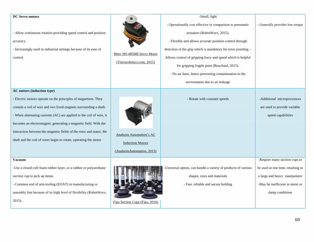
60
DC Servo motors
- Allow continuous rotation providing speed control and position
accuracy
- Increasingly used in industrial settings because of its ease of
control.
Hitec HS-485HB Servo Motor
(Tetrixrobotics.com, 2015)
-Small, light
- Operationally cost effective in comparison to pneumatic
actuators (RobotWorx, 2015).
- Flexible and allows accurate position control through
detection of the grip which is mandatory for error proofing. -
Allows control of gripping force and speed which is helpful
for gripping fragile parts (Bouchard, 2015).
- No air lines, hence preventing contamination to the
environment due to air leakage
- Generally provides low torque
AC motors (induction type)
- Electric motors operate on the principles of magnetism. They
contain a coil of wire and two fixed magnets surrounding a shaft.
- When alternating currents (AC) are applied to the coil of wire, it
becomes an electromagnet, generating a magnetic field. With the
interaction between the magnetic fields of the rotor and stator, the
shaft and the coil of wires begin to rotate, operating the motor
Anaheim Automation’s AC
Induction Motors
(AnaheimAutomation, 2015)
- Rotate with constant speeds
-Additional microprocessors
are used to provide variable
speed capabilities
Vacuum
-Use a closed-cell foam rubber layer, or a rubber or polyurethane
suction cup to pick up items.
- Common end of arm tooling (EOAT) in manufacturing or
assembly line because of its high level of flexibility (RobotWorx,
2015).
Fipa Suction Cups (Fipa, 2016)
-Universal option, can handle a variety of products of various
shapes, sizes and materials
- Fast, reliable and secure holding
-Require many suction cups to
be used at one time, resulting in
a large and heavy manipulator
-May be inefficient in moist or
damp conditions

61
Appendix 4 - Equations Describing the Three gripping modes (Brown et al., 2010)
d = width of pinched region =1.07 ± 0.07 mm; σ∗ =stress magnitude along which pinched region acts on the
object = 50 ± 4 kPa, θ = contact angle to the point where the object is enveloped by the gripper (range:
π/4 < θ < π/2), and μ = coefficient of friction ≈ 1 for rubber.
1) The frictional mechanism alone can contribute to a holding force Fh of:
Below a minimum angle θ ≈ π∕4, the gripping strength is insignificant except for a small contribution from
residual membrane stickiness. The friction mechanism is found to be operative in all cases - resisting forces in
all directions and torques applied at the surface at approximately the same magnitude.
2) The suction mechanism enhances the holding force Fh to be:
For smooth spherical objects, the pinched region of the gripper against the object can simulate an effective O-
ring and form an airtight seal which contributes an additional vertical suction force Fs. This gripping scenario
also holds a vacuum with pressure Pg in the gap region ± θ inside the contact line. The pressure on the pinched
O-ring will keep the vacuum seal in place as long as the frictional stress exceeds the gap pressure Pg,
= Ff/A0 = σ∗ sin θ(μ sin θ – cos θ). The suction mechanism is operative only in several cases, where it is
dependent on the target geometry and force direction.
3) The interlocking mechanism contributes a holding force Fi:

62
Geometrical interlocking occurs when contact angle θ > π∕2, where the elastic membrane effectively conforms
itself to protruding parts of the object depending on its elasticity. The holding force is dependent on a resistance
to both bending and stretching forces exerted on the membrane to enable the object to slip out. Fi captures both
the lower and upper limits of interlocking. The minimum contribution from interlocking, i.e. contact angles θ
<< π∕2, is the amount required to bend the ring wrapped around the sphere
to vertical so the object can slip out, with t as the thickness of the gripper section wrapped around the sphere
and l as the bending arm length. Alternatively, to stretch open the neck of the region wrapped around the object
for it to slip through, a force is required. The upper limit occurs at high interlocking,
i.e. large contact angles θ ≫ π∕2, where large strains are needed to pry open the bag, resulting in
.

63
Appendix 5 – Table 3: Density of Common Granular Materials (Engineering toolbox, 2015)
Material Density (kg/m3)
From To
Coffee, ground - 321
Flour, Corn 481 585
Glass Beads - 1923
Milk powder - 320
Salt, granulated - 1281
Sand 1281 1602
Sugar, granulated - 849
Figure 76: Different grades of Coffee grains, with increasing coarseness from 1 to 4

64
Appendix 6 – Table 4: Tabulation of Pre-Experiment Results of 5” Jamming Gripper
Object , Characteristics/Weight
(g)
Fine Coarse Fine + Coarse
Mixture
Air Water Air Water Air Water
Tweezer, Tip Side 8 ✓ ✓ ✓ ✓ ✓ ✓
Tweezer, Flat Side 8 ✓ X ✓ ✓ ✓ ✓
Pen, Cylindrical 16 ✓ ✓ ✓ ✓ ✓ ✓
Pen, Cylindrical+Clip 16 ✓ ✓ ✓ X ✓ ✓
Watch 82 ✓ ✓ ✓ ✓ ✓ ✓
Legend: ✓= Success in picking up X = Failed to pick up
Figure 77: Left - Fine Grain Coffee used to pick up a tweezer by the tip, Right - Coarse Grain Coffee used to pick up a tweezer by the tip

65
Figure 78: Left - Fine Grain Coffee used to pick up a tweezer by the flat side, Right - Mixture of Fine & Coarse Grain Coffee used to pick up
a tweezer by the flat side
Figure 79: Left - Fine Grain Coffee used to pick up a pen by the cylindrical end, Centre - Coarse Grain Coffee used to pick up a pen by the
cylindrical end, Right - Fine Grain Coffee used to pick up a pen from a bucket of water by the cylindrical end
Figure 80: Left - Fine Grain Coffee used to pick up a watch, Centre - Coarse Grain Coffee used to pick up a watch, Right - A mixture of Fine
& Coarse Grain Coffee used to pick up a watch

66
Appendix 7 – Datasheet for Festo Vacuum Generator, VADMI-45-LS-P

67
Appendix 8 – Datasheet for Festo Pneumatic Accessories
8.1. Festo linear piston (ADN-12-250-APA)

68
8.2. Festo Plastic Tubing PAN-6X1-NT
8.3. Push-in fittings: QSM Quick Star L-shape connector QSML-M5-6

69
Appendix 9 – Datasheet for O-rings
9.1. End-effector face Seal
9.2. End-effector radial Seal

70
9.3. Servo Housing Face Seal
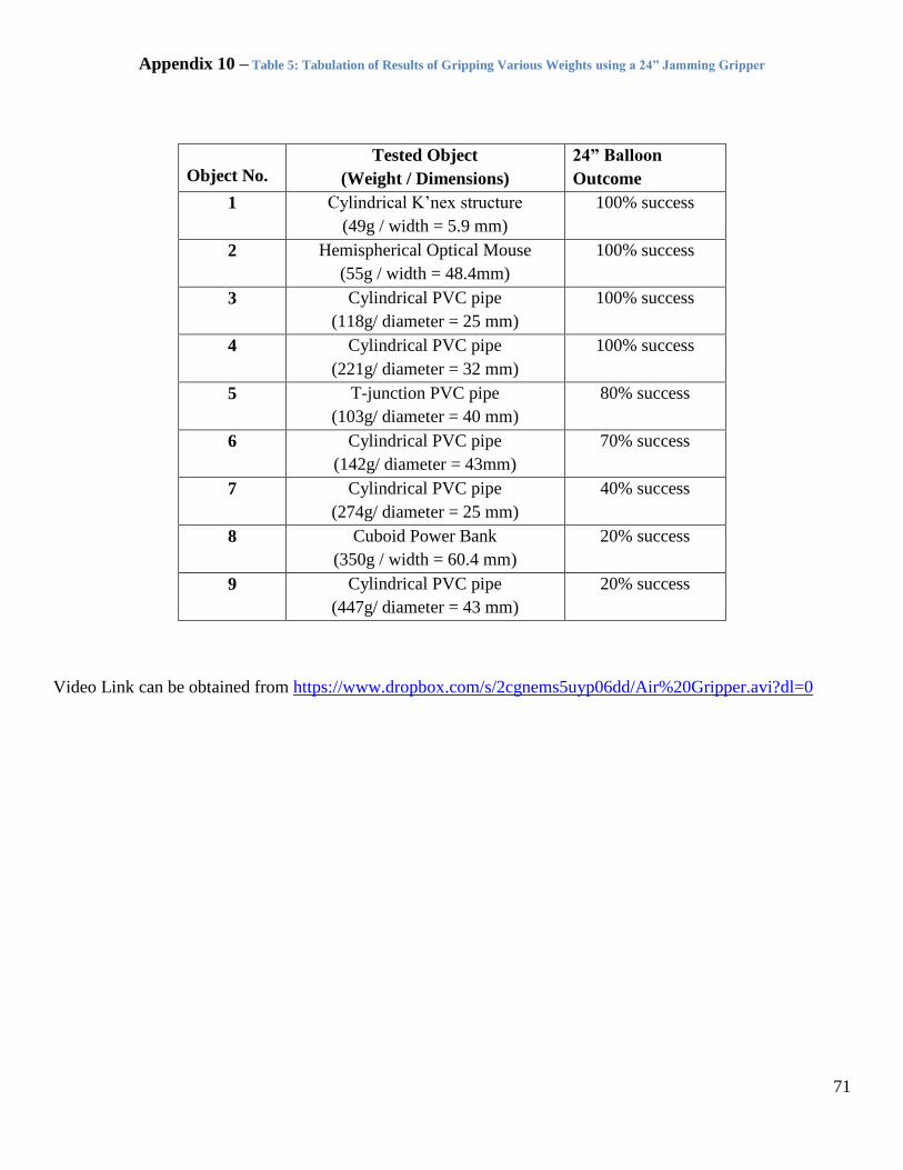
71
Appendix 10 – Table 5: Tabulation of Results of Gripping Various Weights using a 24” Jamming Gripper
Object No.
Tested Object
(Weight / Dimensions)
24” Balloon
Outcome
1 Cylindrical K’nex structure
(49g / width = 5.9 mm)
100% success
2 Hemispherical Optical Mouse
(55g / width = 48.4mm)
100% success
3 Cylindrical PVC pipe
(118g/ diameter = 25 mm)
100% success
4 Cylindrical PVC pipe
(221g/ diameter = 32 mm)
100% success
5 T-junction PVC pipe
(103g/ diameter = 40 mm)
80% success
6 Cylindrical PVC pipe
(142g/ diameter = 43mm)
70% success
7 Cylindrical PVC pipe
(274g/ diameter = 25 mm)
40% success
8 Cuboid Power Bank
(350g / width = 60.4 mm)
20% success
9 Cylindrical PVC pipe
(447g/ diameter = 43 mm)
20% success
Video Link can be obtained from https://www.dropbox.com/s/2cgnems5uyp06dd/Air%20Gripper.avi?dl=0

72
Figure 81: Gripping of Various Objects in air trials; First row (from left) – K’nex structure, Optical Mouse, 25mm cylindrical light PVC
pipe; Second Row (from left) – 32mm cylindrical PVC pipe, T-junction PVC pipe, 43mm cylindrical light PVC pipe; Third Row(from left) -
25mm cylindrical heavy PVC pipe, cuboid power bank, 43mm cylindrical heavy PVC pipe
100% 100% 100%
100% 80% 70%
40% 20% 20%

73
Appendix 11: Servo Datasheet and Torque Calculations
Figure 82: HS-7950TH Servo Specifications (Servocity, 2016)
Figure 83: CAD Model of Manipulator Arm
Torque = weight (W) x perpendicular distance (d) from pivot
Assumptions made: Contribution from the weight of pneumatic tubes, bolts and nuts are taken to be
negligible; a safety factor is incorporated; All components are assumed to be uniform; servo housing and
accessories are along the line of pivot and have no added effect on torque (Weight = 441.49g);

74
g taken to be 9.81m/s^2
Total Weight of Manipulator = ∑W = 1085.08 + 441.49 =1526.57 g
Link 1 W1= 52.03 g, d1 = 19.55 mm
Actuator support W2 = 17.24 g, d2 = 55.27 mm
Linear Piston inclusive of push-in fittings W3 = 379g, d3 = 205.59 mm
Guide Rod W4 = 21.45g, d4 = 442.26mm
EE support W5 = 107.51g, d5 = 611.58mm
EE Collar W6 = 207.85 g, d6 = 641.39 mm
EE Membrane W7 = 300 g, d7 = 702 mm
Stall Torque = (52.03 x 19.55 + 17.24 x 55.27 + 379 x 205.59 + 21.45 x 442.26 + 107.51 x 611.58 + 207.85 x
641.39 + 300x702) x 9.81/1000x1000 = 4.90 Nm
Motor selected: HS 7950TH
, max torque = 17.16 Nm
Max weight that can be lifted with 7.4V power ~1.78 kg in air
Table 6: Tabulation of Stepped-Up Servo HS-7950TH Characteristics
HS7950TH (5:1 ratio) Imperial Units Metric Units
Dimensions: 1.57" x 0.79"x 1.50" 40 x 20 x 38mm
Weight: 2.40oz 68g
Max angle of Rotation 180°
Stall Torque:
4.8V Power
6.0V Power
7.4V Power
1720 oz-in
2010 oz-in
2430 oz-in
12.15 Nm
14.19 Nm
17.16 Nm
Operating Speed
4.8V Power
6.0V Power
7.4V Power
0.9 sec/60° =11.1 rpm
0.75 sec/60° = 13.3 rpm
0.65 sec/60° = 15.4 rpm

75
Appendix 12: Datasheet for 6.4x9x16 TUcRT Spring Energised Rotary Seal from Advanced Sealing
Devices

76
Appendix 13: Images from Water Trials on Gripped Items
Figure 84: Gripping of Various Objects in air trials; First row (from left) – 25mm PVC Pipe, 43mm PVC Pipe, K’nex Structure, Second
Row (from Left): U channel, Odd Geometric Structure, Square tube, Sphere ,Third Row (from left): 2 Pearl Weight, Screwdriver Head,
Kick Board
Video Link can be obtained from https://www.dropbox.com/s/uikm1ps8tq9rj9v/Water%20full%201.avi?dl=0

77
References
Anaheimautomation.com,. (2015). AC Motors, Controllers, and Variable Frequency Drives. Retrieved 31
December 2015, from http://www.anaheimautomation.com/manuals/forms/ac-motor-
guide.php#sthash.rdM5viNL.dpuf
Amend, J., Brown, E., Rodenberg, N., Jaeger, H., & Lipson, H. (2012). A Positive Pressure Universal Gripper
Based on the Jamming of Granular Material. IEEE Transactions on Robotics, 28(2), 341–350.
http://doi.org/10.1109/TRO.2011.2171093
Bouchard, S. (2015). Top 5 Advantages of Servo-Electric Grippers. Blog.robotiq.com. Retrieved 31 December
2015, from http://blog.robotiq.com/bid/37840/Top-5-Advantages-of-Servo-Electric-Grippers
Brown, E., Rodenberg, N., Amend, J., Mozeika, a., Steltz, E., Zakin, M. R., … Jaeger, H. M. (2010). From the
Cover: Universal robotic gripper based on the jamming of granular material. Proceedings of the National
Academy of Sciences, 107(44), 18809–18814. http://doi.org/10.1073/pnas.1003250107
Brighthub Engineering,. (2015). Robotics: Structure of Industrial Robots or Manipulators: Types of Base
Bodies - I. Retrieved 5 December 2015, from http://www.brighthubengineering.com/robotics/26371-
robotics-structure-of-industrial-robots-or-manipulators-types-of-base-bodies-one/
Circuitdigest.com,. (2015). What are industrial manipulators - Different Types of Industrial Manipulators.
Retrieved 5 December 2015, from http://circuitdigest.com/article/what-are-industrial-manipulators
Coastalwiki.org. (2016). Currents - Coastal Wiki. Retrieved 10 April 2016, from
http://www.coastalwiki.org/wiki/Currents
Control Design,. (2015). Festo's DHxS Gripper Series. Retrieved 31 December 2015, from

78
http://www.controldesign.com/vendors/products/2012/festo-dhxs-gripper-series/
Cooney, L. A. (2006). Development of a Low-Cost Underwater Manipulator. Massachusetts Institute of
Technology.
Design Aerospace. (2016). Gears. Retrieved 1 March 2016, from
http://www.daerospace.com/MechanicalSystems/GearsDesc.php
Follmer, S., Leithinger, D., Olwal, A., Cheng, N., & Ishii, H. (2012). Jamming User Interfaces: Programmable
Particle Stiffness and Sensing for Malleable and Shape-Changing Devices. Proceedings of the 25th Annual
ACM Symposium on User Interface Software and Technology - UIST ’12, 519–528.
http://doi.org/10.1145/2380116.2380181
Herman, A. (2013). Shear-jamming in two-dimensional granular materials with power-law grain-size
distribution. Entropy, 15(11), 4802–4821. http://doi.org/10.3390/e15114802
Hyperphysics,. (2015). Bernoulli Equation. Retrieved 15 December 2015, from http://hyperphysics.phy-
astr.gsu.edu/hbase/pber.html
Ikont.co.jp,. (2016). IKO Standard Type Cam Follower CF | Products | IKO NIPPON THOMPSON. Retrieved
1 January 2016, from http://www.ikont.co.jp/eg/product/needle/ndl0601.html
Industrial Circuits Application Note,. (2015). Stepper Motor Basics. Retrieved 31 December 2015, from
http://www.solarbotics.net/library/pdflib/pdf/motorbas.pdf
Jacobsanalytics.com,. (2016). Venturi eductors or vacuum pumps. Retrieved 1 January 2016, from
http://jacobsanalytics.com/eductors/venturi-eductors/
Kuttan, A. (2007). Robotics. New Delhi: I.K. International Publishing House.

79
Misumi,. (2016). CFFAP6-16|Cam Followers/Solid Eccentric|MISUMI|MISUMI. Uk.misumi-ec.com.
Retrieved 1 January 2016, from http://uk.misumi-
ec.com/vona2/detail/110302644810/?HissuCode=CFFAP6-16
Mozeika, A. (2015). Granular Jamming. Retrieved 1 February 2016, from http://www.annan.io/articles/54
Nair, P. (2009). Types of Artificial Gripper Mechanisms - Society of Robotics & Automation. Available at:
http://sra.vjti.info/knowledgebase/posts-on-a-roll-1/gripper-mechanisms
Omron. (2016). Subminiature Basic Switches (S-Size). Retrieved 1 March 2016, from
https://www.omron.com/ecb/products/sw/12/ss.html
Parker. (2006). Rotary Seal Design Guide.
Parker FAQ. (2016) (1st ed.). Retrieved 1 March 2016, from http://www.parker.com/Literature/O-
Ring%20Division%20Literature/FAQ.pdf
Pololu.com,. (2015). Pololu - Stepper Motor: Bipolar, 200 Steps/Rev, 20×30mm, 3.9V, 0.6 A/Phase. Retrieved
31 December 2015, from https://www.pololu.com/product/1204
Ridao, P., Carreras, M., Ribas, D., Sanz, P. J., & Oliver, G. (n.d.). Intervention AUVs : The Next Challenge.
RobotWorx, (2015). Grippers For Robots. Retrieved 31 December 2015 from
https://www.robots.com/articles/viewing/grippers-for-robots
RS Components. (2016). Optek OPB815WZ Chassis Mount Slotted Optical Switch, Phototransistor Output.
Retrieved 1 March 2016, from http://sg.rs-online.com/web/p/slotted-optical-switches/1944030/
Sapagroup.com,. (2016). Aluminum U Channel | Sapa Extrusions North America | Sapa Group. Retrieved 1
January 2016, from http://www.sapagroup.com/en/na/profiles/aluminum-u-channel/

80
Seabotix,. (2015). SeaBotix Inc. Grabber Attachments. Retrieved 5 December 2015, from
http://www.seabotix.com/products/grabber_attachments.htm
Servocity.com,. (2016). Servo Shaft Hub (.500"). Retrieved 1 January 2016, from
https://www.servocity.com/html/servo_shaft_hub___500__.html#.VoX15fl97IU
Tetrixrobotics.com,. (2015). 180° Standard-Scale HS-485HB Servo Motor (W39197). Retrieved 31 December
2015, from http://www.tetrixrobotics.com/180_Standard-Scale_HS-485HB_Servo_Motor
Tigertek Industrial Services,. (2015). How Actuators Work - Basic Actuators for Motion Control. Retrieved 31
December 2015, from http://www.tigertek.com/servo-motor-resources/how-actuators-work-in-motion-
control.html
Vacuum cups, suction cups and suction pads. (2016). Fipa.com. Retrieved 4 February 2016, from
http://www.fipa.com/en_GB/products/212414-vacuum-cups
Xu, N., & Ching, E. S. C. (2010). Effects of particle-size ratio on jamming of binary mixtures. The Royal
Society of Chemistry 2010, 5. http://doi.org/10.1039/b926696h