Embed Size (px)
Citation preview
August 2011 Edition (Rev Dec 12) i
Design & Maintenance Guide 18
Design of Catering Facilities
This guide shall be read in conjunction with Specification 42 – Catering Equipment Specification and the relevant Scales contained in JSP 315 - Services Accommodation Code and JSP 456 – Defence Catering Manual.

DMG 18 Design of Catering Facilities
© Crown Copyright 2012 Application for reproduction should be made to: - The Copyright Unit Her Majesty's Stationery Office St Clements House 2-16 Colegate Norwich NR3 1BQ First Edition Crown Copyright 1992 Second Edition Crown Copyright 1999 Third Edition Crown Copyright 2004 Fourth Edition Crown Copyright 2005 Fifth Edition Crown Copyright 2006 Sixth Edition Crown Copyright 2007 Seventh Edition Crown Copyright 2008 Eighth Edition Crown Copyright 2009 Ninth Edition Crown Copyright 2110 Tenth Edition Crown Copyright 2011 Tenth Edition (rev) Crown Copyright 2012 ISBN 0 11 772927 2
August 2011 Edition (Rev Dec 12) ii
DMG 18 Design of Catering Facilities
Foreword
1. This guide replaces the previous Defence Estates Design and Maintenance Guide 18 – Design of Catering Facilities published in September 1999 and its subsequent amendments dated August 2004 to 2011. A table of the amendments is enclosed within this publication
2. This guide is prepared by Defence Infrastructure Organisation Professional &
Technical Services – Catering & Technical Support Team primarily for use in contracts, which include the provision of new build or refurbished Service kitchens, dining rooms or leisure facilities and the provision of new or replacement catering equipment.
3. When this guide is used in connection with a Defence contract it is to be read
in conjunction with the document setting out the contractual requirements particular to that contract.
4. Whilst this guide was commissioned for use on MOD contracts, it is
acknowledged that it could be usefully applied to other contracts. It may, therefore, be used outside the MOD estate, however, no warranty is given as to the accuracy of this specification or its fitness for any purpose.
5. This guide has been devised for the use of the Crown and its contractors in
the execution of contracts for the Crown. The Crown hereby excludes all liability (other than liability for death or personal injury) whatsoever and howsoever arising (including, but without limitation, negligence on the part of the Crown, its servants or agents) for any loss or damage however caused where this document is used for any other purpose.
CONTACTS FOR QUERIES
Professional & Technical
Services Professional & Technical Services Catering & Technical
Support Building Standards Kingston Drive Spur 12, Beckford Sutton Coldfield Ensleigh WestMidlands Bath B757RL BA1 5AB 01225 468115 / 9355
68115 021 311 2135 OR
0161 4267487 / 96571 7487
August 2011 Edition (Rev Dec 12) iii
DMG 18 Design of Catering Facilities Contents
Contents AMENDMENTS RECORD SECTION 1 INTRODUCTION 1.1 INTRODUCTION 1.2 KITCHEN DESIGN AND FOOD SAFETY 1.3 OPERATIONAL REQUIREMENTS 1.4 INFORMATION REQUIRED FOR DESIGN PURPOSES 1.5 JSP 315 SERVICES ACCOMMODATION AND DE SPECIFICATION 42
CATERING EQUIPMENT SPECIFICATION 1.6 THE ROLE OF THE KITCHEN DESIGN AND EQUIPMENT AUTHORITY 1.7 ADVICE PROCEDURE SECTION 2 CATERING AREAS – KEY CONSIDERATIONS
2.1 APPLICATION 2.2 SPATIAL STANDARDS 2.3 WORK FLOW PATTERNS 2.4 KITCHEN 2.5 CROCKERY WASH 2.6 UTENSIL WASH 2.7 PASTRY PREPARATION 2.8 LARDER 2.9 RAW MEAT PREPARATION 2.10 VEGETABLE PREPARATION AND STORAGE 2.11 DAY STORE (Formally KITCHEN FOOD STORE) 2.12 KITCHEN EQUIPMENT STORE 2.13 BULK REFRIGERATION/FREEZER STORE 2.14 BULK GROCERY STORE 2.15 KITCHEN OFFICE 2.16 EXTERNAL REFUSE AREA (DELIVERY & REFUSE) 2.17 CLEANERS ROOM 2.18 NORWEGIAN CONTAINER WASH SECTION 3 SERVERY 3.1 SERVERY 3.2 BACK BAR 3.3 PANTRY 3.4 SIDEBOARD 3.5 ENTRANCE LOBBY AND QUEUE SPACE 3.6 CLOAKS AND TOILETS
August 2011 Edition (Rev Dec 12) iv
DMG 18 Design of Catering Facilities Contents
SECTION 4 DINING ROOM 4.1 DINING AREA 4.2 PANTRY 4.3 SIDEBOARD 4.4 CROCKERY, GLASS AND LINEN STORE 4.5 CLEANERS ROOM SECTION 5 STAFF FACILITIES 5.1 STAFF FACILITIES SECTION 6 CATERING CONTROL 6.1 INTRODUCTION 6.2 RAW MEAT PREPARATION 6.3 GROCERY STORE 6.4 CATERING CONTROL OFFICES SECTION 7 FINISHES AND SERVICES 7.1 INTRODUCTION PART A INFRASTRUCTURE 7.2 FLOORS 7.3 WALLS 7.4 CEILINGS 7.5 DOORS 7.6 WINDOWS PART B SERVICES & SERVICES COORDINATION 7.7 DRAINAGE & WASTE DISPOSAL 7.8 WATER SUPPLY 7.9 GAS 7.10 ELECTRICITY & LIGHTING 7.11 VENTILATION 7.12 HEATING 7.13 SERVICES CO-ORDINATION 7.14 FIRE PRECAUTIONS PART C INFESTATION 7.15 INFESTATION PART D ENERGY MANAGEMENT 7.16.1 ENERGY MANAGEMENT
August 2011 Edition (Rev Dec 12) v
DMG 18 Design of Catering Facilities Contents
PART E WASTE MANAGEMENT 7.17 FOOD WASTE MANAGEMENT SECTION 8 COMBINED KITCHENS INTRODUCTION PLANNING CONSIDERATIONS SECTION 9 BARS AND CELLARS 9.1 INTRODUCTION 9.2 PLANNING CONSIDERATIONS REFERENCES GLOSSARY
August 2011 Edition (Rev Dec 12) vi

DMG 18 Design of Catering Facilities Amendments
Amendments Record
Amendments to August 2005 Edition
Section
Para
Page No.
Changed by Details of Changes & Date
Effective Change Date
c v Contents amended to account for additions to Section 2.
MM 01 Mar. 05
Aug 05
1 1.4 7/8 Reference to the provision of Amenity (Catering, Retail & Leisure) Facilities including 3:1/4:1/PAYD provision.
MM 01 Mar. 05
Aug 05
1 1.4 8 Note 5 amended to reflect amendments to JSP 315, Scale 39, Part 6-Catering Control.
MM 01 Mar. 05
Aug 05
1 1.5 10 Reference to 4:1 added. MM 01 Mar. 05
Aug 05
1 1.6 13 KDEA schedule amended. MM 01 Mar. 05
Aug 05
2 16 to 33
Page numbers changed to introduce additional information. Includes format change and additional pages up to Page 36.
MM 01 Mar. 05
Aug 05
2 2.3 19 Diagram updated to include Raw Meat Prep MM 01 Mar. 05
Aug 05
2 2.9 to
2.18
27 to 36
Additional rooms added to compliment the amendments to JSP 315, Scale 39 and deletion of the detail in Part 6. List of rooms runs concurrently with JSP 315, Scale 39, Part 2, Serial 32. Rooms added: -Raw Meat Prep, Bulk Grocery Store, Refrigeration/Freezer Store.
MM 01 Mar. 05
Aug 05
3 37 Page numbers changed to commence at Page 37. MM 01 Mar. 05
Aug 05
3 3.1 & 3.5
39 Reference to 4:1 added. MM 01 Mar. 05
Aug 05
3 3.1 39 “Officers & SNCOs’ Messes Servery” – Paragraph added to address door widths between serveries and front of house to allow the passage of mobile serveries.
MM 11 Mar 05
Aug 05
3 3.2 39 Paragraph added to address individual and global electrical isolation to back bar equipment.
MM 11 Mar 05
Aug 05
4 42 Page numbers changed to commence at Page 42. MM 11 Mar 05
Aug 05
5 46 Page numbers changed to commence at Page 46 MM 11 Mar 05
Aug 05
6 48 Page numbers changed to commence at Page 48 MM 11 Mar 05
Aug 05
6 6.1/2 49/50
References to Section 2 and Day Store amended. 16 Mar 05 Aug 05
7 52/ 85
Page numbers changed to commence at Page 52. 25 May 05 Aug 05
August 2011 Edition (Rev Dec 12) Amendments -1
DMG 18 Design of Catering Facilities Amendments
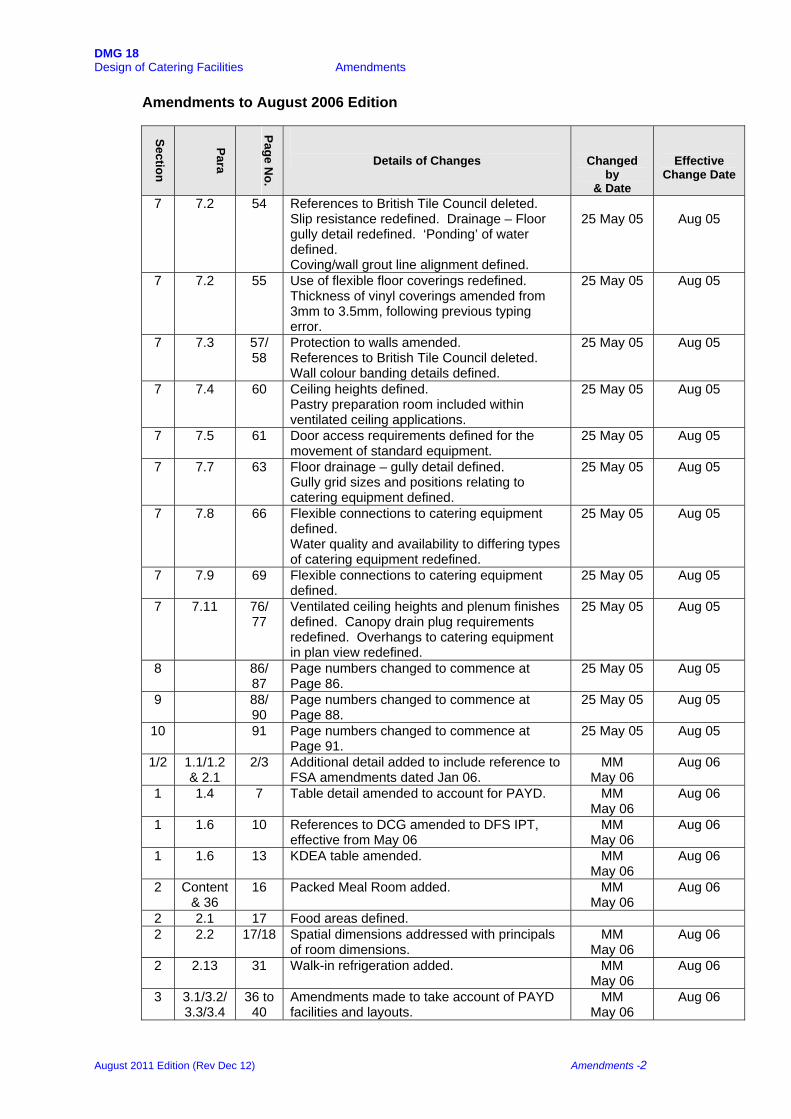
Amendments to August 2006 Edition
Section
Para
Page No.
Details of Changes
Changed by
& Date
Effective Change Date
7 7.2 54 References to British Tile Council deleted. Slip resistance redefined. Drainage – Floor gully detail redefined. ‘Ponding’ of water defined. Coving/wall grout line alignment defined.
25 May 05
Aug 05
7 7.2 55 Use of flexible floor coverings redefined. Thickness of vinyl coverings amended from 3mm to 3.5mm, following previous typing error.
25 May 05 Aug 05
7 7.3 57/ 58
Protection to walls amended. References to British Tile Council deleted. Wall colour banding details defined.
25 May 05 Aug 05
7 7.4 60 Ceiling heights defined. Pastry preparation room included within ventilated ceiling applications.
25 May 05 Aug 05
7 7.5 61 Door access requirements defined for the movement of standard equipment.
25 May 05 Aug 05
7 7.7 63 Floor drainage – gully detail defined. Gully grid sizes and positions relating to catering equipment defined.
25 May 05 Aug 05
7 7.8 66 Flexible connections to catering equipment defined. Water quality and availability to differing types of catering equipment redefined.
25 May 05 Aug 05
7 7.9 69 Flexible connections to catering equipment defined.
25 May 05 Aug 05
7 7.11 76/ 77
Ventilated ceiling heights and plenum finishes defined. Canopy drain plug requirements redefined. Overhangs to catering equipment in plan view redefined.
25 May 05 Aug 05
8 86/ 87
Page numbers changed to commence at Page 86.
25 May 05 Aug 05
9 88/ 90
Page numbers changed to commence at Page 88.
25 May 05 Aug 05
10 91 Page numbers changed to commence at Page 91.
25 May 05 Aug 05
1/2 1.1/1.2 & 2.1
2/3 Additional detail added to include reference to FSA amendments dated Jan 06.
MM May 06
Aug 06
1 1.4 7 Table detail amended to account for PAYD. MM May 06
Aug 06
1 1.6 10 References to DCG amended to DFS IPT, effective from May 06
MM May 06
Aug 06
1 1.6 13 KDEA table amended. MM May 06
Aug 06
2 Content & 36
16 Packed Meal Room added. MM May 06
Aug 06
2 2.1 17 Food areas defined. 2 2.2 17/18 Spatial dimensions addressed with principals
of room dimensions. MM
May 06 Aug 06
2 2.13 31 Walk-in refrigeration added. MM May 06
Aug 06
3 3.1/3.2/ 3.3/3.4
36 to 40
Amendments made to take account of PAYD facilities and layouts.
MM May 06
Aug 06
August 2011 Edition (Rev Dec 12) Amendments -2
DMG 18 Design of Catering Facilities Amendments
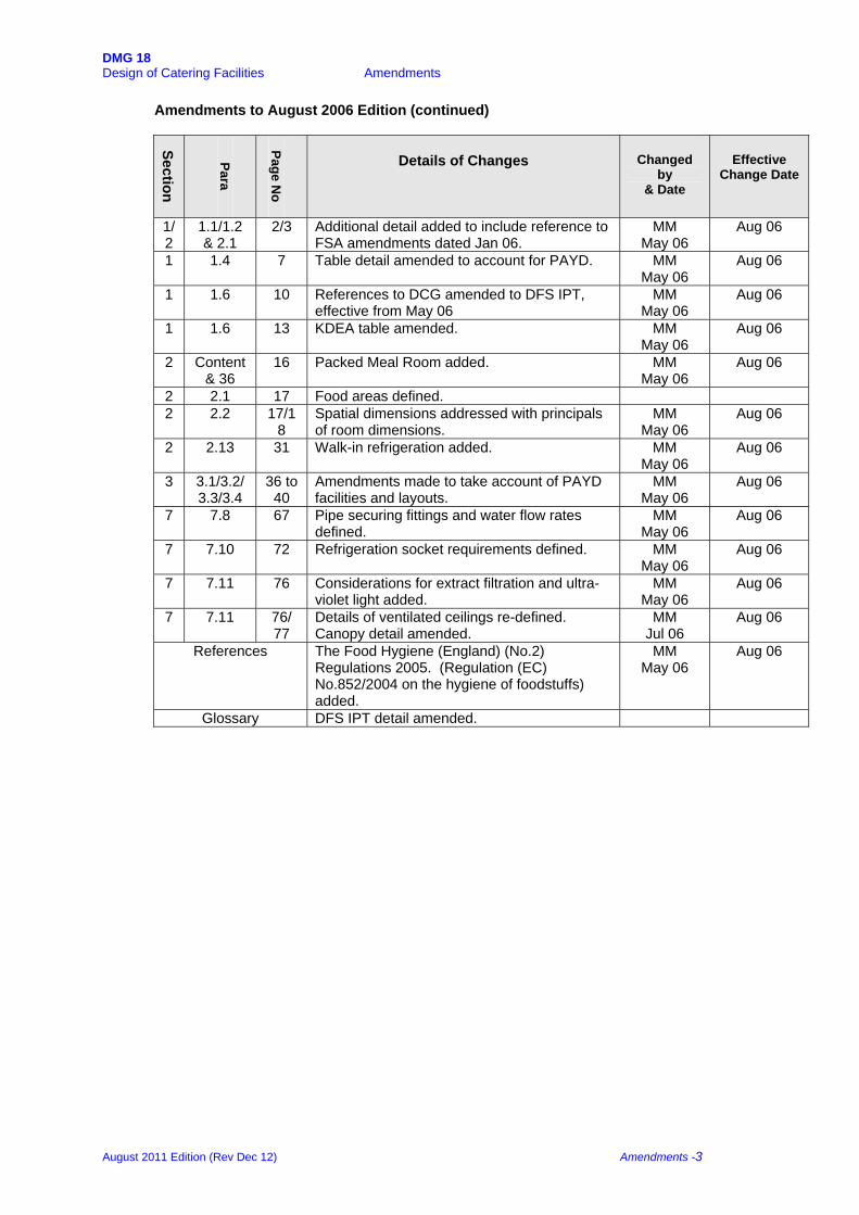
Amendments to August 2006 Edition (continued)
Section
Para
Page N
o
Details of Changes
Changed
by & Date
Effective
Change Date
1/2
1.1/1.2 & 2.1
2/3 Additional detail added to include reference to FSA amendments dated Jan 06.
MM May 06
Aug 06
1 1.4 7 Table detail amended to account for PAYD. MM May 06
Aug 06
1 1.6 10 References to DCG amended to DFS IPT, effective from May 06
MM May 06
Aug 06
1 1.6 13 KDEA table amended. MM May 06
Aug 06
2 Content & 36
16 Packed Meal Room added. MM May 06
Aug 06
2 2.1 17 Food areas defined. 2 2.2 17/1
8 Spatial dimensions addressed with principals of room dimensions.
MM May 06
Aug 06
2 2.13 31 Walk-in refrigeration added. MM May 06
Aug 06
3 3.1/3.2/ 3.3/3.4
36 to 40
Amendments made to take account of PAYD facilities and layouts.
MM May 06
Aug 06
7 7.8 67 Pipe securing fittings and water flow rates defined.
MM May 06
Aug 06
7 7.10 72 Refrigeration socket requirements defined. MM May 06
Aug 06
7 7.11 76 Considerations for extract filtration and ultra-violet light added.
MM May 06
Aug 06
7 7.11 76/ 77
Details of ventilated ceilings re-defined. Canopy detail amended.
MM Jul 06
Aug 06
References The Food Hygiene (England) (No.2) Regulations 2005. (Regulation (EC) No.852/2004 on the hygiene of foodstuffs) added.
MM May 06
Aug 06
Glossary DFS IPT detail amended.
August 2011 Edition (Rev Dec 12) Amendments -3

DMG 18 Design of Catering Facilities Amendments
Amendments to August 2007 Edition
Section
Para
Page N
o
Details of Changes
Changed
by
Effective
Change Date
1 1.3 7 Detail of Catering Questionnaire added. MM Aug 07 1 1.5 9 JSP 315, Scale 39 amendments re-defined. MM Aug 07 1 1.5 10 Reference to JSP 456 added. MM Aug 07 1 1.6 13 DFS IPT contacts list updated. Detail of
reorganisation as @ Dec 07 added. MM Aug 07
1 1.7 14/ 16
Advice procedure amended to meet the Regional Prime Contracts (RPC) arrangements.
MM Aug 07
2 2.5 22 Utilisation of heat recovery systems added. MM Aug 07 2 2.8/9 27/
28 Temperature details amended. MM Aug 07
2 2.16 34/ 36
Section amended to take account of newly introduced environmental issues.
MM Aug 07
7 7.2 56/ 59
Floor tile specifications further defined to account for the use of non pedestrian traffic. Use of vinyl sheeting expanded. Use of resin system floors expanded.
MM Aug 07
7 7.3 59 Wall protection detail amended. MM Aug 07 7 7.4 62 Ceiling height defined.
Applicable areas for suspended ceilings defined.
MM Aug 07
7 7.7 68 Food waste procedures updated. MM Aug07 7 7.8 69 Allowable water treatment and conditioning
systems amended to provide flexibility of use. MM
Aug 07
7 7.11 78 Temperature details amended. MM Aug 07 7 7.13 82 Co-ordination of water treatment systems
sited adjacent to equipment defined. MM Aug 07
9 9.2 92/ 94
Finishes and fitting details expanded. MM Aug 07
August 2011 Edition (Rev Dec 12) Amendments -4
DMG 18 Design of Catering Facilities Amendments
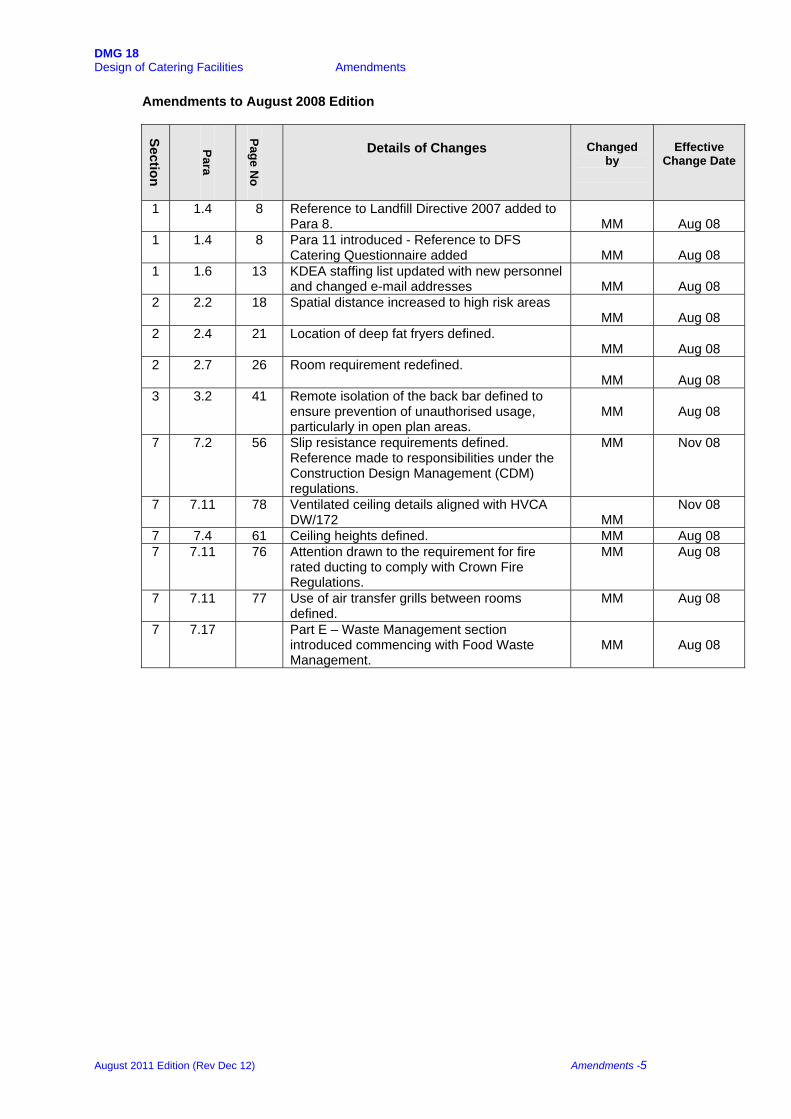
Amendments to August 2008 Edition
Section
Para
Page N
o
Details of Changes
Changed
by
Effective
Change Date
1 1.4 8 Reference to Landfill Directive 2007 added to Para 8.
MM
Aug 08
1 1.4 8 Para 11 introduced - Reference to DFS Catering Questionnaire added
MM
Aug 08
1 1.6 13 KDEA staffing list updated with new personnel and changed e-mail addresses
MM
Aug 08
2 2.2 18 Spatial distance increased to high risk areas MM
Aug 08
2 2.4 21 Location of deep fat fryers defined. MM
Aug 08
2 2.7 26 Room requirement redefined. MM
Aug 08
3 3.2 41 Remote isolation of the back bar defined to ensure prevention of unauthorised usage, particularly in open plan areas.
MM
Aug 08
7 7.2 56 Slip resistance requirements defined. Reference made to responsibilities under the Construction Design Management (CDM) regulations.
MM Nov 08
7 7.11 78 Ventilated ceiling details aligned with HVCA DW/172
MM
Nov 08
7 7.4 61 Ceiling heights defined. MM Aug 08 7 7.11 76 Attention drawn to the requirement for fire
rated ducting to comply with Crown Fire Regulations.
MM Aug 08
7 7.11 77 Use of air transfer grills between rooms defined.
MM Aug 08
7 7.17 Part E – Waste Management section introduced commencing with Food Waste Management.
MM
Aug 08
August 2011 Edition (Rev Dec 12) Amendments -5
DMG 18 Design of Catering Facilities Amendments
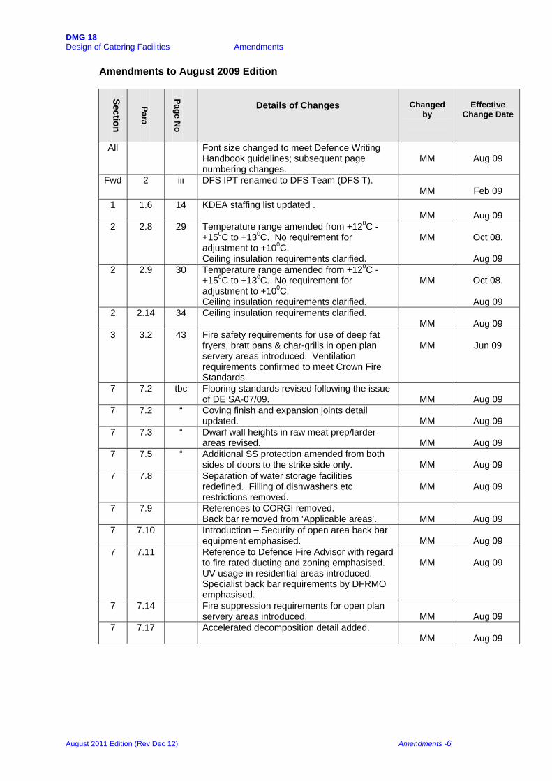
Amendments to August 2009 Edition
Section
Para
Page N
o
Details of Changes
Changed
by
Effective
Change Date
All Font size changed to meet Defence Writing Handbook guidelines; subsequent page numbering changes.
MM
Aug 09
Fwd 2 iii DFS IPT renamed to DFS Team (DFS T). MM
Feb 09
1 1.6 14 KDEA staffing list updated . MM
Aug 09
2 2.8 29 Temperature range amended from +120C - +150C to +130C. No requirement for adjustment to +100C. Ceiling insulation requirements clarified.
MM
Oct 08.
Aug 09
2 2.9 30 Temperature range amended from +120C - +150C to +130C. No requirement for adjustment to +100C. Ceiling insulation requirements clarified.
MM
Oct 08.
Aug 09
2 2.14 34 Ceiling insulation requirements clarified. MM
Aug 09
3 3.2 43 Fire safety requirements for use of deep fat fryers, bratt pans & char-grills in open plan servery areas introduced. Ventilation requirements confirmed to meet Crown Fire Standards.
MM
Jun 09
7 7.2 tbc Flooring standards revised following the issue of DE SA-07/09.
MM
Aug 09
7 7.2 “ Coving finish and expansion joints detail updated.
MM
Aug 09
7 7.3 “ Dwarf wall heights in raw meat prep/larder areas revised.
MM
Aug 09
7 7.5 “ Additional SS protection amended from both sides of doors to the strike side only.
MM
Aug 09
7 7.8 Separation of water storage facilities redefined. Filling of dishwashers etc restrictions removed.
MM
Aug 09
7 7.9 References to CORGI removed. Back bar removed from ‘Applicable areas’.
MM
Aug 09
7 7.10 Introduction – Security of open area back bar equipment emphasised.
MM
Aug 09
7 7.11 Reference to Defence Fire Advisor with regard to fire rated ducting and zoning emphasised. UV usage in residential areas introduced. Specialist back bar requirements by DFRMO emphasised.
MM
Aug 09
7 7.14 Fire suppression requirements for open plan servery areas introduced.
MM
Aug 09
7 7.17 Accelerated decomposition detail added. MM
Aug 09
August 2011 Edition (Rev Dec 12) Amendments -6

DMG 18 Design of Catering Facilities Amendments
Amendments to August 2010 Edition
Section
Para
Page N
o
Details of Changes
Changed
by
Effective Change
Date
1 1.1 1.2. Reference to the introduction of the Equality Act 2110 introduced
MM
Aug 10
1 1.6 1.13 Changes to KDEA staffing. MM
Aug 10
2 2.16 2.37 Wet Refuse section expanded to account for new technology installations.
MM Aug 10
7 7.3 7.62 Requirement for non-white finish walls deleted.
MM Aug 10
7 7.10 7.78 Electrical socket fascias defined. Requirement for additional sockets defined.
MM Aug 10
7 7.11 7.84 Use of canopies with sinks and expansion water boilers re-defined.
MM Aug 10
7 7.17 7.95 Part E text re-edited throughout MM Aug 10
August 2011 Edition (Rev Dec 12) Amendments -7
DMG 18 Design of Catering Facilities Amendments
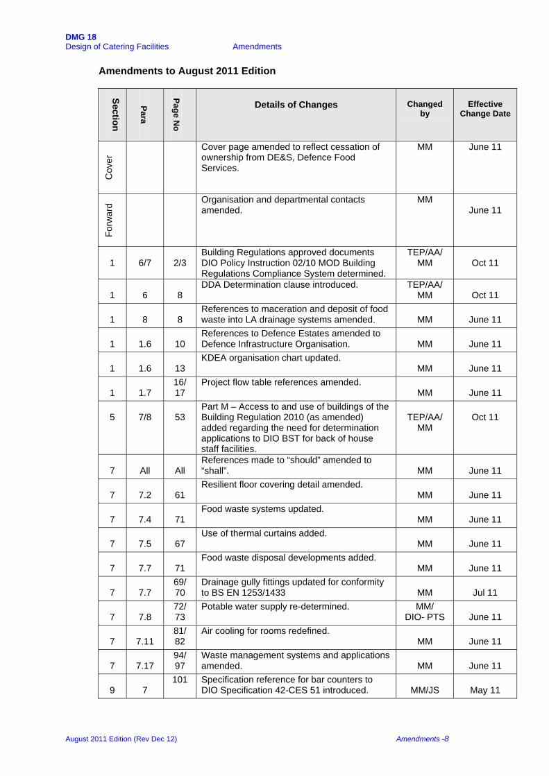
Amendments to August 2011 Edition
Section
Para
Page N
o
Details of Changes
Changed
by
Effective
Change Date C
over
Cover page amended to reflect cessation of ownership from DE&S, Defence Food Services.
MM June 11
Forw
ard Organisation and departmental contacts
amended. MM
June 11
1
6/7
2/3
Building Regulations approved documents DIO Policy Instruction 02/10 MOD Building Regulations Compliance System determined.
TEP/AA/ MM
Oct 11
1
6
8
DDA Determination clause introduced. TEP/AA/ MM
Oct 11
1
8
8
References to maceration and deposit of food waste into LA drainage systems amended.
MM
June 11
1
1.6
10
References to Defence Estates amended to Defence Infrastructure Organisation.
MM
June 11
1
1.6
13
KDEA organisation chart updated. MM
June 11
1
1.7
16/ 17
Project flow table references amended. MM
June 11
5
7/8
53
Part M – Access to and use of buildings of the Building Regulation 2010 (as amended) added regarding the need for determination applications to DIO BST for back of house staff facilities.
TEP/AA/
MM
Oct 11
7
All
All
References made to “should” amended to “shall”.
MM
June 11
7
7.2
61
Resilient floor covering detail amended. MM
June 11
7
7.4
71
Food waste systems updated. MM
June 11
7
7.5
67
Use of thermal curtains added. MM
June 11
7
7.7
71
Food waste disposal developments added. MM
June 11
7
7.7
69/ 70
Drainage gully fittings updated for conformity to BS EN 1253/1433
MM
Jul 11
7
7.8
72/ 73
Potable water supply re-determined. MM/ DIO- PTS
June 11
7
7.11
81/ 82
Air cooling for rooms redefined. MM
June 11
7
7.17
94/ 97
Waste management systems and applications amended.
MM
June 11
9
7
101 Specification reference for bar counters to DIO Specification 42-CES 51 introduced.
MM/JS
May 11
August 2011 Edition (Rev Dec 12) Amendments -8

DMG 18 Design of Catering Facilities Amendments
Glo
ssar
y Agency details amended. MM June 11
August 2011 Edition (Rev Dec 12) Amendments -9
DMG 18 Design of Catering Facilities Amendments
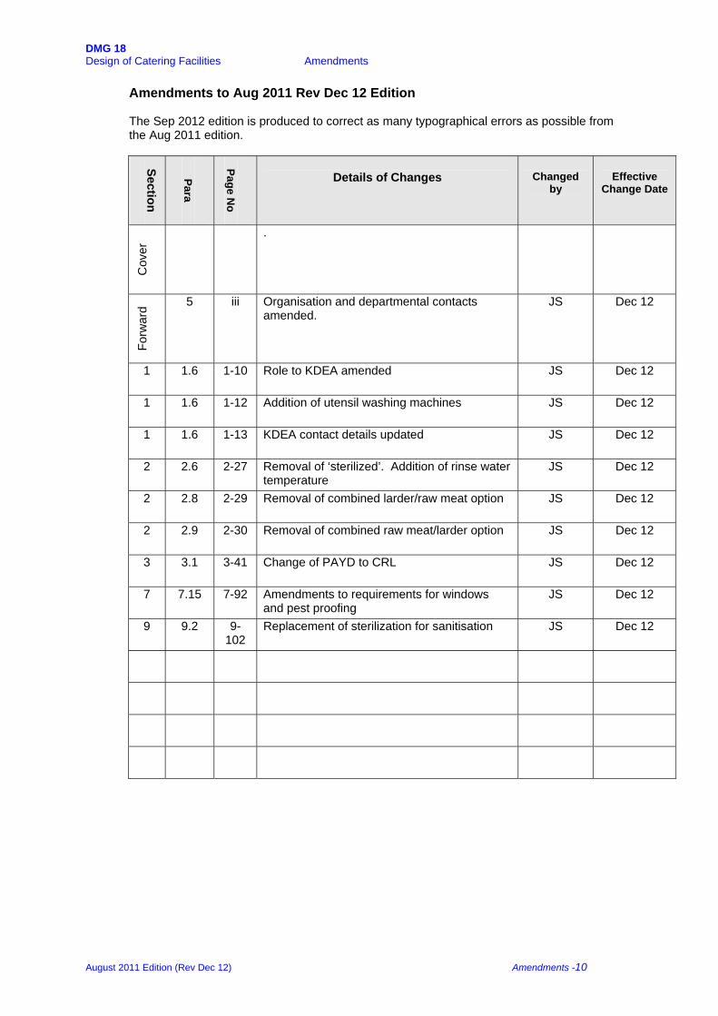
Amendments to Aug 2011 Rev Dec 12 Edition
The Sep 2012 edition is produced to correct as many typographical errors as possible from the Aug 2011 edition.
Section
Para
Page N
o
Details of Changes
Changed
by
Effective
Change Date
Cov
er .
Forw
ard 5 iii Organisation and departmental contacts
amended. JS Dec 12
1 1.6 1-10 Role to KDEA amended JS Dec 12
1 1.6 1-12 Addition of utensil washing machines JS Dec 12
1 1.6 1-13 KDEA contact details updated JS Dec 12
2 2.6 2-27 Removal of ‘sterilized’. Addition of rinse water temperature
JS Dec 12
2 2.8 2-29 Removal of combined larder/raw meat option JS Dec 12
2 2.9 2-30 Removal of combined raw meat/larder option JS Dec 12
3 3.1 3-41 Change of PAYD to CRL JS Dec 12
7 7.15 7-92 Amendments to requirements for windows and pest proofing
JS Dec 12
9 9.2 9-102
Replacement of sterilization for sanitisation JS Dec 12
August 2011 Edition (Rev Dec 12) Amendments -10

DMG 18 DMG 18 Section 1 Introduction Design of Catering Facilities
1
Introduction SECTION 1 INTRODUCTION
1.1 INTRODUCTION
1.2 KITCHEN DESIGN AND FOOD SAFETY
1.3 OPERATIONAL REQUIREMENTS
1.4 INFORMATION REQUIRED FOR DESIGN PURPOSES 1.5 JSP 315 SERVICES ACCOMMODATION AND DE SPECIFICATION
42-CATERING EQUIPMENT SPECIFICATION 1.6 THE ROLE OF THE KITCHEN DESIGN AND EQUIPMENT
AUTHORITY
1.7 ADVICE PROCEDURE
August 2011 Edition (Rev Dec 12) 1 -1

DMG 18 DMG 18 Section 1 Introduction Design of Catering Facilities
1 Introduction 1.1 INTRODUCTION
This guide deals with the design of kitchens and serveries for all ranks and dining rooms for Junior Ranks only. Spatial details of dining rooms for Officers and SNCOs are given in JSP 315 Services Accommodation Code, Scales 29 and 34 respectively.
Nothing in this guide absolves the Project Manager, Property Managers and other agencies concerned from complying with all relevant legislation, regulations, British Standards, European Normalisation and Codes of Practice including Defence Infrastructure Organisation (DIO) publications, such as Design Guides, Technical Bulletins and Policy Instructions.
The guide is intended to be a practical help in the design of kitchens, serveries and dining rooms and assumes that "normal conditions" apply (i.e. a ground floor location with level access for deliveries and that there are no particular restrictions). It deals specifically with the layout of equipment and departments and provides guidance on the functional relationships. Additionally, it contains the requirements for finishes, services and building requirements. Compliance with the guide will ensure that facilities will meet MOD requirements and satisfy current food safety and hygiene legislation. Where it is proposed to deviate, agreement of the relevant Kitchen Design and Equipment Authority (KDEA) should be sought (see Section 1.6).
Catering for large numbers in Service messes requires specialist knowledge to ensure that facilities are designed and equipped to meet the present and foreseeable demand at the minimum military requirement and to the MOD defined standards.
The introduction of The Food Safety Act 1990 (FSA), The Food Safety (General Food Hygiene) Regulations 1995 (The Act), and The Food Hygiene (England) (No.2) Regulations 2006 (Regulation (EC) No.852/2004 on the hygiene of foodstuffs)1 have had a profound effect on the standard to which current and future catering facilities must conform. Early consultation with all disciplines and interested parties is recommended to ensure that every aspect of the design is covered. Failure to seek specialist advice can result in non-compliance with legislation, nugatory expenditure on inadequate or unnecessary equipment and increased operating costs due to over-large facilities or poor equipment layout.
Facilities shall be provided in accordance with the design solutions as contained in the Approved Documents that support the Building Regulations (as amended). The procedures for ensuring compliance with the Building Regulations are set out in DIO Policy Instruction 02/10 MOD Building Regulations Compliance System. Consideration should also be given to the Disability Discrimination Act. (DDA) From 01 Oct 10 the majority of the Equality Act 2010 will be implemented and replace major parts of the provision of the DDA. Both Acts are published on the website of the Office of Public Sector Information.
1(and equivalent regulations in Scotland, Wales and Northern Ireland)
August 2011 Edition (Rev Dec 12) 1 -2

DMG 18 DMG 18 Section 1 Introduction Design of Catering Facilities
Compliance with the Building Regulations via the MOD Building Regulations Compliance System and other primary legislation relating to fire safety is mandatory. In addition, compliance with the Crown Fire Standards is mandatory and shall be applied to all service catering facilities.
1.2 KITCHEN DESIGN AND FOOD SAFETY
Kitchen planning principles are based on the requirements of the The Food Hygiene (England) (No.2) Regulations 2006 (The Act) (Regulation (EC) No.852/2004 on the hygiene of foodstuffs)
The Act clearly sets out in some detail, the general requirement for food premises. These may be termed as the performance specification for the planning of food premises. To set these in architectural and building terms, the design and construction of all food premises should: -
• Allow for the building to be kept clean and maintained in good condition and
repair. • Enable adequate cleaning and/or disinfecting. • Provide prevention against the accumulation of dirt, contact with toxic
materials or the shedding of particles into food. • Inhibit the formation of condensation or mould. • Facilitate good hygiene practices. • Provide appropriate temperature conditions for the processing and storage of
products. • Provide protection of cross contamination between and during operations – by
foodstuffs, equipment, materials, water, air supply, personnel or by external sources, including pests.
These general requirements are followed by more focused requirements, some specific to selected aspects of a building including washbasins, lavatories, sanitary conveniences, changing facilities, ventilation, air flow, lighting and drainage.
The Act then lists the requirements for the interior of a building with regard to floor and wall surfaces, wall construction, ceilings and overhead fixtures, windows, doors, surfaces in contact with food, facilities for cleaning and disinfecting tools and equipment, and provision for the washing of food.
These requirements, which apply to permanent buildings, also apply to mobile or temporary facilities.
CROSS CONTAMINATION
The above tabulation of the requirements of The Act shows that the core planning criteria centres on designing of facilities to avoid cross contamination of foodstuffs. The separation of raw and cooked foods is essential in meeting these criteria and can be achieved by:
• The physical separation of raw and cooked meat products. • The use of separate workbenches. • The use of separate refrigerators. • The use of separate staff.
August 2011 Edition (Rev Dec 12) 1 -3

DMG 18 DMG 18 Section 1 Introduction Design of Catering Facilities
HAZARD CONTROL
In practical terms, the planning and operation of kitchen and dining facilities is based to a large extent upon Hazard Analysis Critical Control Points (HACCP) processes. Modern catering and distribution techniques have increased the number of stages in the food production chain, and therefore the number of opportunities for bacteria and contamination to enter the food chain. There is therefore an increased necessity for hazard identification, control, and the increased awareness of working conditions.
HACCP identifies four main hazards that may arise within catering premises, all of them relate to contamination:
• By bacteria or other micro-organisms that cause food poisoning. • By chemicals such as cleaning materials or pest baits. • By foreign materials such as glass, metal or plastic. • By water.
Architecturally, efficient planning and design and the selection of types of construction and materials can control hazards. PLANNING AND DESIGN
The planning of a catering facility and its detailed design is the fundamental basis of the control of the hazards within which good management and working practice take place. In addition to providing for the function of the building and the activities within it, the layout and design of the buildings should allow access for effective cleaning. All hazards are important but the most pressing is contamination. This should be controlled within the layout and planning of the building including external, internal and circulation routes.
Cross contamination is controlled by:
• Planning separate entries and exits to and from the building so as to reduce
cross contamination by separation. This includes cross contamination at the point of delivery of stores and fresh foods, exit of rubbish and swill and the movement of people in and out of the building.
• Planning for a minimum of entries and exits to and from the building so that the management of movement in and out of the building can control cross contamination.
• The design and layout of individual spaces, including internal circulation and movement within spaces and rooms, such that there are clean and non-clean areas.
• The design of the kitchen and dining facilities being based on a clean area in which the central kitchen, all food preparation areas and all areas occupied by personnel in "chefs' protective clothing" is clearly separated from dirty areas and from people in “street” clothes.
• Minimising the movement through and between rooms (e.g. dirty vegetables do not enter the Veg Prep area through the kitchen; they enter the Veg Prep through a door at the delivery end of the room and only the clean, prepared vegetables enter the kitchen through a separate door). The Veg Prep generates a lot of waste, which is taken directly outside (or macerated) and does not contaminate the clean vegetables, the raw vegetables or the kitchen.
August 2011 Edition (Rev Dec 12) 1 -4
DMG 18 DMG 18 Section 1 Introduction Design of Catering Facilities
• Separation of functions between spaces. Clean functions should be kept separate from dirty functions - (e.g. a corridor separates the refuse area and swill area from the kitchen area). Visitors in “street” clothes have the opportunity to change into clean protective clothing upon entry to the building or to meet with staff in the “dirty” office.
• Provision for separation of activities within spaces including preparation areas, hot and cold (Larder), cooking areas, cold holding (refrigerated storage) and hot holding (Servery).
• Management and monitoring of these separate spaces can be facilitated by the provision of dwarf walls between the activities.
• Provision for sufficient spaces within rooms. The layout of spaces should be such that high-risk foods can be prepared on separate work surfaces and equipment.
• Storage of edible foodstuffs being kept separate from toxic cleaning materials and swill; fish is kept separate from meat; dairy products are kept separate from vegetables etc. There should be marked shelves, locked cupboards and organised shelving.
• Menu choice has an effect on the use of the kitchen especially of storage and preparation – fresh or frozen produce or both. This requires that sufficient chilling and frozen storage equipment be provided for flexibility.
• Keeping foods separate within workspaces (e.g. dry goods, seasonings, daily ingredients, liquids in chilled drawers, etc). Provision should be made for the holding and handling of foods at appropriate controlled temperatures.
• The design of functional relationships between rooms. Ease of direct and indirect access between rooms to provide efficient flows of operation.
• The layout, planning and design of the building should avoid the possible accumulation of dirt. Provision for easy access to all areas and surfaces for cleaning is essential. This is particularly important in kitchen and preparation areas where there should be no awkward corners or areas inaccessible to cleaners or cleaning machines.
CONSTRUCTION AND MATERIALS The Industry Guide to Good Hygiene Practice; Catering Guide, which is an interpretative guide to The Food Safety Act, states the two overriding concerns, which have to be addressed by the architecture.
• “The internal surfaces of the structure and equipment fixed to the structure, including light fittings, ventilation and any other equipment must be visually clean and in a good state of repair.”
• “Food premises must be maintained to a standard that will allow effective cleaning”.
The appropriate use of construction and materials must allow both of these concerns to be met and to allow for the type of cleaning appropriate to each area. The spread of bacteria and the containment of contamination can be controlled by materials and construction.
• Construction materials should not include any substance that may add toxic
materials to food either by direct contact or by vapour. Finishes should be such that they do not lead to shedding of particles.
• There should be positive airflow between critical areas including the provision of air at the correct temperatures, e.g. cool air in the larder and the avoidance of any build up of condensation.
August 2011 Edition (Rev Dec 12) 1 -5

DMG 18 DMG 18 Section 1 Introduction Design of Catering Facilities
• Appropriate insulating materials should be used in order to control temperatures within refrigerated cold rooms. Internal walls should be of solid construction to prevent the harbourage of pests.
• Other considerations such as work patterns, movement of equipment or control of activities will override this consideration (e.g. the use of dwarf or screen walls between the Kitchen and the Larder and the Pastry Preparation). In these spaces the ambient temperature at the work surfaces can be controlled by the flow of the cooled air.
• Floors should be laid to allow for the desired flow of water during cleaning and be finished with the appropriate non-slip, easy to clean and maintain covering material such as ceramic floor tiles, vinyl safety flooring or cast in situ resin flooring. The selection of the type of flooring will depend upon the load imposed upon it from items on castors designed to be mobile or fixed legs and static. From the point of view of hygiene and maintenance, ceramic tiles or cast in situ resin flooring are recommended – the latter particularly when above normal wear or loading is expected. Ceramic non-slip tiles with resin grout are the preferred option.
• Wall materials should be easy to maintain and to keep clean; traditionally wall tiles are used. Care needs to be taken with the installation of skirting and coving that they do not have a ledge that collects dust. New materials that are PVC based and which can be welded and jointed into continuous sheets have provided an alternative. Wall sheets can also be welded to PVC based floor coverings to form a continuous, impervious and easily maintained and cleaned surface covering. However plastic coated boards have vertical and horizontal joints, which can be problematic. Ceramic tiles with resin grout are the preferred choice.
• Integrated ceilings should be provided which contain integral lighting and ventilation systems in a sealed unit with a hygienic surface that is easily cleaned and maintained. The hanging of light fixtures, ducts and pipework from the ceiling is not acceptable.
• The provision of adequate and appropriate working conditions with regard to temperature, air purity and lighting must be considered.
1.3 OPERATIONAL REQUIREMENTS
MOD catering is of a very high standard and offers the diner a wide menu choice. The catering facilities are used 365 days per year and sometimes 24 hours per day. To meet this workload it is essential that all equipment is of heavy-duty quality, (and strengthened as necessary) and the internal finishes of the building fabric are very durable and where necessary, protected from damage (see Section 7). There are differing messing patterns for each type of mess; these may differ from mess to mess. The designer should ensure that all the relevant information regarding the types of service and clearance required for all meals is obtained at an early stage.
The time that junior ranks spend in the dining room is short, during each meal period; service density and speed of throughput is, therefore, essential and needs to be borne in mind when designing the servery and front of house. Consideration will also need to be given to CRL/PAYD when facilities are open throughout the day. This may not apply to Officers' and SNCOs' messes.
August 2011 Edition (Rev Dec 12) 1 -6
DMG 18 DMG 18 Section 1 Introduction Design of Catering Facilities
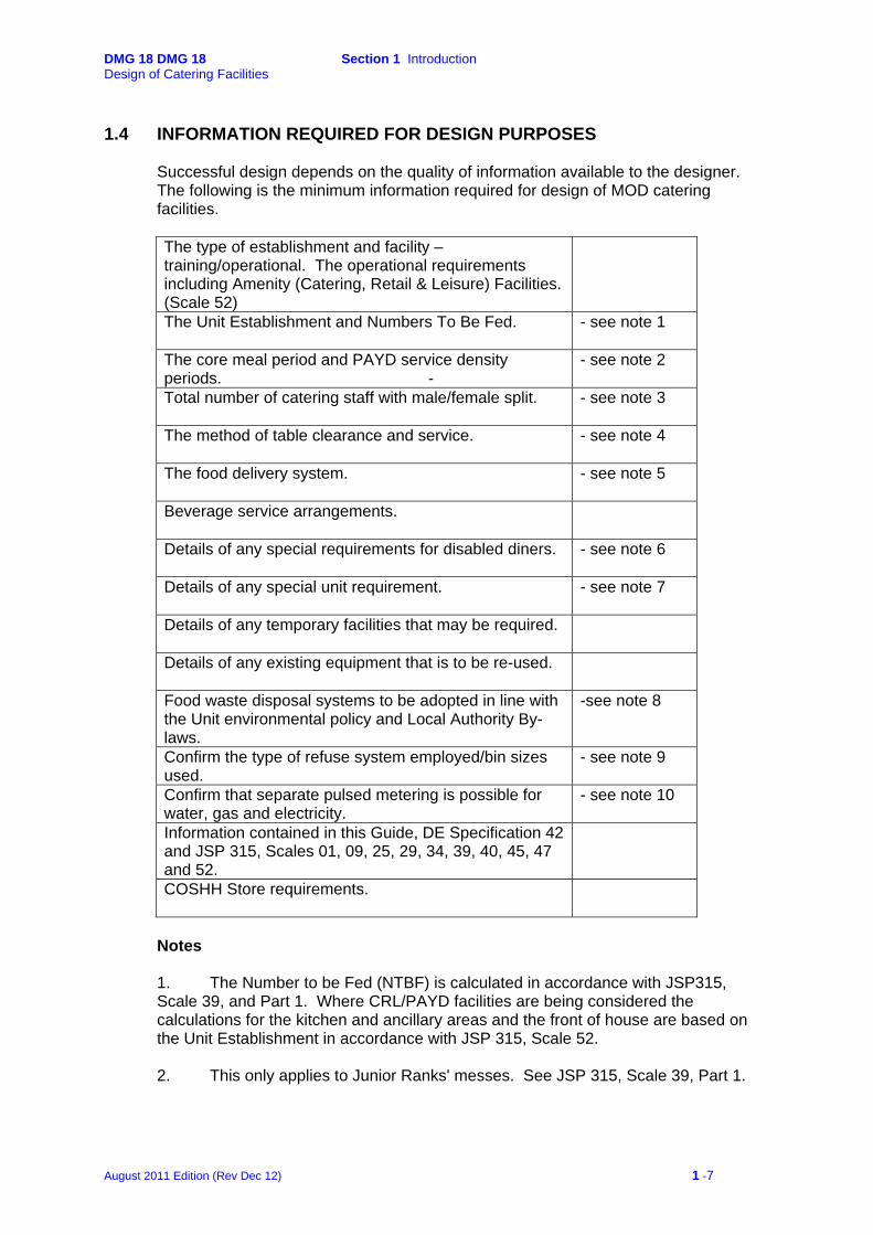
1.4 INFORMATION REQUIRED FOR DESIGN PURPOSES
Successful design depends on the quality of information available to the designer. The following is the minimum information required for design of MOD catering facilities.
The type of establishment and facility – training/operational. The operational requirements including Amenity (Catering, Retail & Leisure) Facilities. (Scale 52)
The Unit Establishment and Numbers To Be Fed.
- see note 1
The core meal period and PAYD service density periods. -
- see note 2
Total number of catering staff with male/female split.
- see note 3
The method of table clearance and service.
- see note 4
The food delivery system.
- see note 5
Beverage service arrangements.
Details of any special requirements for disabled diners.
- see note 6
Details of any special unit requirement.
- see note 7
Details of any temporary facilities that may be required.
Details of any existing equipment that is to be re-used.
Food waste disposal systems to be adopted in line with the Unit environmental policy and Local Authority By-laws.
-see note 8
Confirm the type of refuse system employed/bin sizes used.
- see note 9
Confirm that separate pulsed metering is possible for water, gas and electricity.
- see note 10
Information contained in this Guide, DE Specification 42 and JSP 315, Scales 01, 09, 25, 29, 34, 39, 40, 45, 47 and 52.
COSHH Store requirements.
Notes
1. The Number to be Fed (NTBF) is calculated in accordance with JSP315, Scale 39, and Part 1. Where CRL/PAYD facilities are being considered the calculations for the kitchen and ancillary areas and the front of house are based on the Unit Establishment in accordance with JSP 315, Scale 52. 2. This only applies to Junior Ranks' messes. See JSP 315, Scale 39, Part 1.
August 2011 Edition (Rev Dec 12) 1 -7

DMG 18 DMG 18 Section 1 Introduction Design of Catering Facilities
3. The total number of male and female staff is needed to calculate the size of the staff facilities – see JSP 315, Scale 39, Part 5 and Scale 01. 4. This particularly applies to Junior Ranks' messes, where clearance can be either by catering staff or the diner. The choice of method will affect the design and location of the crockwash area. Officers may have full steward service at each meal. SNCOs' usually collect their food from the servery at each meal but the catering staff clear the tables. All messes operate differently and the designer should ensure that sufficient information is obtained regarding the service of all meals to ensure that an acceptable system is installed. 5. The Food Supply contract generally operates a system of Direct Delivery to Individual Messes. Where exceptionally, delivery is to a Central Point within the unit, the KDEA should be consulted for advice on the spatial and equipment requirements. 6. Full disabled facilities are not provided for catering staff due to the requirement for staff to be physically able bodied to be able to carry out their duties within the kitchen. However, visitors to the dining room will require those facilities and as such sanitary conveniences should be designed in accordance with guidance contained within Approved Document M – Access to and use of buildings.
7. Special requirements can include out of hours feeding, preparation of in-flight meals, packed/container meals for consumption on ranges or training areas etc. 8. The disposal of soft wet waste needs to be considered in conjunction with the capabilities of the main drainage system and the by-laws enforced by the local authority with regard to the discharge of waste into the drainage system. A suitable food waste management system needs to be included taking into account The Environmental Protection Act 1990 and the subsequent Directives contained within including the Landfill Directive 2010. 9. The type of collection determines the design of the refuse area system employed by the unit. The number of collections made weekly will determine the number of bins required and subsequently the area required for their storage. The type of bin used will determine the type of refuse compactor to be installed. 10. Catering areas are required to be able to report energy consumption remote from the rest of the building in which they are located. A pulsed meter facility should be available for all utilities capable of being interrogated by a Building Energy Management System (BEMS).
11. A Catering Questionnaire Data Sheet is produced by DIO CTS staff and should be completed to assist designers with the particular unit requirements in consultation with the KDEA.
1.5 JSP SCALES & DE SPECIFICATION No. 42 – CATERING EQUIPMENT
SPECIFICATION
PUBLICATIONS
In addition to this guide, the designer will need a copy of the latest issue of JSP 315 - Service Accommodation Code Scales 01, 09, 25, 29, 34, 39, 40, 45, 47, 52; JSP 456 – Defence Catering Manual and DE Specification 42 – Catering Equipment Specification.
August 2011 Edition (Rev Dec 12) 1 -8
DMG 18 DMG 18 Section 1 Introduction Design of Catering Facilities
JSP 315 - SERVICE ACCOMMODATION CODE JSP 315 is the general standard set by the MOD, with the agreement of HM Treasury, for the provision of accommodation for the regular British Armed Forces. Scale 01. Gives guidance on the application of all scales and information on matters that are common to them. Scale 39. This scale is the basic document used for the design of Service catering facilities and applies equally to new build and refurbishment or conversion of permanent premises. The applications generally apply to the provision of facilities to Officers’ and SNCOs’ messes; provisions for Junior Ranks’ messes are included in Scale 52. The scale gives information and guidance to those concerned with the provision of accommodation. When applied in accordance with MOD policies and procedures, the Scale provides a sound basis for financial control in achieving value for money in both initial capital costs and subsequent maintenance. The scale is not to be read as a rigid entitlement and is not specific to any particular project, but it is flexible enough to meet the requirements of most Service catering facilities. Where a unit has a particular requirement, the Scale may be varied, however, any variation will need to be justified in accordance with the policies and procedures prescribed in JSP 414 – Management Strategy, JSP 434 – Property Management and JSP 435 – Works Projects. Where variations are proposed the advice of the KDEA should be sought. The information contained is based on the NTBF, which should be calculated in accordance with Part 1 of the Scale. It is impossible to design any Service catering facility unless the Establishment figure is confirmed and agreed and from which the NTBF is obtained.
The inherent flexibility in any catering facility allows the NTBF to be grouped into Scale bands eg, NTBF 264 – Use of Scale band 201 to 300. Scale bands apply to Parts 2 to 4B inclusive and Parts 6 to 8 of the Scale.
Part 4 provides details of the Spatial Standards for the Kitchen and Ancillaries areas and the Front of House, based on the Unit’s Establishment for trained units; and the Unit’s Establishment and AAOT trainees and students (for Phase 1 and 2 Training Establishments) Staff facilities should be provided in accordance with Part 5 of the Scale. It is impossible to design staff facilities unless the number of male and female staff is known. (See also Scale 40).
Part 6 of the Scale refers to details of the catering control facility. Where food is provided to one central point in a unit the KDEA should be consulted to identify the accommodation and equipment to be provided for those units. This system is rarely provided in today's modern facilities. The most common system throughout the MOD is where food is delivered direct to individual messes. Normally, Catering Control facilities are not required; however, the Mess will require additional storage areas and equipment as detailed in Part 2, Serial 32 of the Scale. In many instances, particularly in large messes and in Army Junior Ranks' messes, there will be a
August 2011 Edition (Rev Dec 12) 1 -9
DMG 18 DMG 18 Section 1 Introduction Design of Catering Facilities
requirement for an Accounts Office and the Regimental Catering Warrant Officer (RCWO) (see also Section 6 of this guide). Scale 40. This Scale covers the provision of changing room and locker facilities for those personnel who need to change into protective or alternative clothing at their place of work. (see also Scale 39, Part 5). Scale 45. This Scale applies to all MOD office accommodation, both military and civilian. Scale 47. This Scale applies to rest room and standby room accommodation.
Scale 52. This scale applies to the provision of Amenity (Catering, Retail and Leisure) Facilities for Junior Ranks following the introduction of 4:1 facilities and Pay As You Dine (PAYD) and should be read in conjunction with Scale 39. JSP 456 – DEFENCE CATERING MANUAL JSP 456, Defence Catering Manual (DCM) provides a combination of regulations, instructions, advice and is a point of reference for Service caterers to assist them in the delivery of the catering function across the entire range and diversity of Armed Forces catering. DE SPECIFICATION 42 – CATERING EQUIPMENT SPECIFICATION This specification defines the minimum standards for catering equipment normally found in service catering facilities and shall be applied to all equipment detailed in JSP 315, Scales 39 and 52. Particular attention should be made to the General Specification Notes at the front of the document; any equipment not covered by a Specification shall comply with the standards set out under that section. Unless otherwise stated, accommodation and equipment shall be provided only in accordance with the Scales and DE Specification 42 – Catering Equipment Specification. (see Defence Infrastructure Organisation Web links below.) - http://www.mod.uk/DefenceInternet/Microsite/dio/ http://www.mod.uk/DefenceInternet/MicroSite/DIO/OurPublications/TechnicalDocuments/MTP/
1.6 THE ROLE OF THE KITCHEN DESIGN AND EQUIPMENT AUTHORITY (KDEA)
Specialist advice from the KDEA is available to Project Sponsors, Property Managers and their Consultants or Contractors engaged in MOD work. Advice and guidance should be obtained from the KDEA at the earliest possible stage. JSP 456 Vol 4 Ch 11 refers. The formation of the DIO CTS Team has brought together the single service kitchen design and catering equipment advisers to create a fully integrated, tri-Service Equipment and Infrastructure Team. The keystone of the team’s work is to develop more cost effective, improved catering facilities that fully meet complex statutory legislation and user requirements.
August 2011 Edition (Rev Dec 12) 1 -10
DMG 18 DMG 18 Section 1 Introduction Design of Catering Facilities
The team is the focal point for MOD kitchen design and catering equipment, primarily for major projects, to refurbish existing kitchens and to build new messes in addition to smaller property management tasks where specialist catering design advice will secure a value for money solution. Much of the work is to advise Requirements Managers, Property Managers and Catering Consultants employed by Project Contractors of the MoD’s kitchen design requirements and catering equipment specifications; as a consequence, the KDEA will spend much of their time on site visits inspecting projects. A principal aspect of the KDEA role is to provide an in-depth inspection prior to completion of a project. This will include aspects of the provision and functionality of the catering equipment and the provision, standard of finish and compliance of the infrastructure including structural finishes and services. A report is produced prior to the formation of the Handover Board to determine the facility's "fitness for purpose". The report is based on the documents previously referred to at 1.5 above, including this Guide, all of which are used as the benchmark for the required standard of installation and finish. Designers and Contractors will be required to make the facility ready for the inspection on the agreed date, the requirements of which are shown under.
FINAL PRE-HANDOVER INSPECTION
The Contractor is required to action the following:
1. Commissioning. All items of equipment shall be commissioned and tested to the Contractor’s satisfaction. All equipment shall be fully assembled and be laid out ready for use by the occupier as per the latest revision of the Contractor’s drawings. 2. Testing – Cooking Equipment. All prime equipment shall be made ready for testing and demonstration as follows: • Range tops, ovens and grills to be lit at least ten minutes prior to inspection
commencement.
• Deep fat fryers to be filled with the minimum level of oil and to be lit at least ten minutes prior to inspection commencement.
• Combination ovens and steamers to be made ready to demonstrate the
programming, cooking, steaming and drain down modes. • Tilting kettles, bratt pans and bains-marie to be filled to the maximum load line
and turned on at least ten minutes prior to inspection commencement. • Water boilers to be switched on ready for demonstration. 3. Testing – Refrigeration. All refrigerators, freezers, chillers and thawing cabinets shall be made ready for testing and demonstration as follows: • All to be turned on at least 24 hours prior to the inspection.
• Air cooling units in Larders to be turned on at least 24hours prior to inspection
with benefit of a record of achieved temperatures.
August 2011 Edition (Rev Dec 12) 1 -11
DMG 18 DMG 18 Section 1 Introduction Design of Catering Facilities
• Refrigerated drinks dispensers and beverage units to be made ready for draw off. 4. Testing – Sinks. All sinks shall be made ready for testing and demonstration as follows: • Sink bowls to be half filled with water (food preparation, crock wash, utensil
wash).
• Sanitation sink to be half filled with water and the heater element turned on at least 45 minutes prior to inspection.
• All dishwashers, utensil washers and glass-washer to be made ready to
demonstrate the wash, dry and drain down modes. 5. Testing – Service Equipment. Service counters shall be made ready for testing and demonstration as follows: • Hot counters and soup station to be switched on with the hot cupboard, bain-
marie and gantry lights operational at least 30 minutes prior to the inspection.
• Cold counters to be switched on with refrigerated cabinet, dole well and lighting operational at least 2 hours prior to inspection.
• Ambient lighting to be switched on at time of inspection.
• Heated plate lowerators to be switched on and operating at their working
temperature.
• Gastronorm containers to be sited adjacent to the equipment to which they relate. 6. Testing – Ventilation. The ventilation system shall be made ready for testing and demonstration as follows: • All doors and windows to rooms are to be closed.
• The ventilation system to be turned on in all rooms.
• Individual canopy extraction units to be turned on prior to inspection.
• Steam and smoke tests are to be carried out at the time of inspection.
7. Hygienic Clean. All internal walls, floors, windows, gullies/channels and equipment (both internal and external) shall be hygienically cleaned prior to the hand-over. This clean is to be of a standard to allow immediate occupation and delivery of foods to be stored, prepared and cooked. i.e. fit for purpose. Sweeping out builders’ rubbish is not sufficient for a kitchen to be assessed as ‘fit for purpose’. To ensure there is no proliferation of pathogens, or residual chemicals, responsible for food borne disease or health risks, all surfaces and equipment must be hygienically cleaned. Not only is this cleaning work essential in terms of Food Safety Regulations, it must be undertaken in a timely manner i.e. there is no point cleaning a kitchen, then sending in tradesmen to undertake further building work. See: "Specification for the Hygienic Cleaning of Food Rooms and Catering Equipment on Completion of a Building Project.” (a derivative of DE Specification 38).
August 2011 Edition (Rev Dec 12) 1 -12
DMG 18 DMG 18 Section 1 Introduction Design of Catering Facilities
KITCHEN DESIGN AND EQUIPMENT AUTHORITY (KDEA)
Defence Infrastructure Organisation Professional & Technical Services
Spur 12 Beckford Ensleigh
Bath BA1 5AB
Peter Hughes
Head PTS Hard FM
Professional & Technical Services Building Standards
Ms Tracy Price Principal Building Surveyor
Catering & Technical Support
Miss Julie Stilwell PTS2b2 – Property Management & Equipment/KDEA
01225 468115 9355 68115
e-mail: [email protected]
Fax: 9355 67252 or 01225 467252
Mr Pete Hudson PTS2b4 – Infrastructure & Projects/KDEA
0161 4267487 96571 7487
Mobile: 07990 785296 e-mail: [email protected]
August 2011 Edition (Rev Dec 12) 1 -13
DMG 18 DMG 18 Section 1 Introduction Design of Catering Facilities
1.7 ADVICE PROCEDURE
The KDEA is available to assist with the preparation of the Statement of Requirement (SOR) in the production of order of cost estimates and option studies evaluation and development of the Brief, attend siting boards, and to advise on options to be considered.
WORKS SERVICES Works services can be defined as the construction, enlargement or modification of a building or fixed facility. Works services are divided into two categories:
a. Major Capital Projects (Core Works). b. Minor New Works (Core Services).
There are no hard financial limits which distinguish when a project is considered to be Core Works, or Core Service. A risk based judgement by the delivery organisation (Defence Infrastructure Organisation) will be made based on complexity of the project, capability, capacity and competence of DE and its supply chain. PROJECT FLOW The chart at Figure 1 shows the flow of a project from identification through to financial completion. Unit/establishment catering staff will have input to these projects through the relevant staff, particularly during the early period of the Project Identification stages. The Equipment and Infrastructure staff of DFS IPT, as the KDEA, should be informed at the earliest opportunity so that sound specialist direction can be given from the outset of the project. Whilst it is noted that there is constant contact between interested parties involved in a project, unit, establishment and area catering staff should not deal directly with project staff after the consultation with DFS IPT has begun. All requests for amendments and changes to catering facilities should be directed to the relevant DFS IPT project manager who will advise both catering and project staff as to the viability of the request. KEY PERSONNEL The following is a list of personnel who may be involved in a works project and an outline of their role: -
• User. The user of a facility whose operation is the driving force behind a contract. The user may be a budget holder from unit/establishment through to Top Level Budget (TLB) holder.
• Project Staff Officer. A member of the budget holder’s staff who handles daily project business until a Project Manager is appointed.
• Budget Manager. A member of the budget manager’s staff responsible for co-ordination of expenditure profiles and fiscal advice to the budget holder.
• Site Establishment Representative (SER). A MOD official appointed by the Commanding Officer/Head of Establishment responsible for normal daily property management issues.
• Project Manager. A professional construction industry project manager, appointed by the delivery organisation, responsible to Defence Estates for overseeing the design and construction process and to manage the daily business of the project.
August 2011 Edition (Rev Dec 12) 1 -14

DMG 18 DMG 18 Section 1 Introduction Design of Catering Facilities
• Defence Infrastructure Organisation Project Manager (DIO PM). A member of DIO responsible for co-ordination of all DIO provided services to the project.
• Contracts Officer. A member of the Defence Contracts Organisation responsible for all non construction, contractual aspects of the project.
• Regional Prime Contractor (RPC). The commercial company, contracted to Defence Infrastructure Organisation, and responsible for the construction work and through life maintenance.
August 2011 Edition (Rev Dec 12) 1 -15

DMG 18 DMG 18 Section 1 Introduction Design of Catering Facilities
Figure 1 - Project Flow Maintenance Period The KDEA is available to provide 3, 6, and 12-month "Project Performance in Use"
inspections following the hand-over of the kitchen and provide reports and observations to the Project Sponsor as required.
Stage 1
Project Identification
Stage 2
Strategy and Briefing
Stage 3 Engagement with DIO and
Appointment of DIO PM Manager and the Project
Manager
Stage 4
Project Planning and Preliminary Design
Stage 5
Detailed Design, Tender Preparation and Final
Project Approval
Stage 6
Tender Invitation, Evaluation and Contract
Award
Stage 7
Works Contract Period
Stage 8
Maintenance Period
Stage 9
Financial Completion
Unit/establishment and Area catering staff will need to be involved in the early stage of any catering related project and should assist in the completion of the Statement of Need. DIO CTS staff must be involved at the earliest opportunity to act as the Subject Matter Experts (SMEs) in the completion of the Statement of Requirement (SOR) and Option Study.
DIO CTS SMEs will be available to assist the Project Sponsors in the completion of the Project Brief.
Core activity of the Requirements Manager, Budget Holder and Contracts Officer.
DIO CTS SMEs will support the DIO PM in the production of preliminary designs, value engineering (through the Peer Review Team) and assist in the production of the Design Brief.
In liaison with unit and area catering staff, DIO CTS SMEs will assist in the design of all catering facilities and the scaling of all catering equipment. Defence Infrastructure Organisation will be responsible for the detailed design of all works, incorporating the catering equipment.
Core activity of the Requirements Manager, Project Manager and Contracts Officer. DIO will manage the commercial activity of all works related contracts.
In liaison with unit and area catering staff, DIO CTS SMEs will monitor work on all catering facilities and the quality/specification of all the catering equipment & provide appropriate reports. Other duties during this phase will include the specialist inspections for the Acceptance Board.
Core activity of DIO RPC. DIO CTS SMEs will provide 3 & 12-month ‘Project Performance in Use’ inspections following the Handover to the Authority & provide appropriate reports.
Core activity of DIO RPC.
August 2011 Edition (Rev Dec 12) 1 -16

DMG 18 DMG 18 Section 1 Introduction Design of Catering Facilities
OBTAINING APPROVAL Although each Service has a slightly different form for initiating this procedure the process for obtaining approval, shown at Figure 2, follows the same basic format. Advice should be sought from the property management team as to the procedures to be adopted. At all stages of the process scrutiny by Subject Matter Experts (SMEs) should be sought. The staff at DIO CTS, if involved at the earliest stages, will be available to give clear advice to all members of the approval system and may be able to save a great deal of time and effort. Figure 2 - Minor New Works (Core Service) Approval
No
Approve/Reject.
HILOConducts financial scrutiny and approves or rejects bid. Returns the bid to the SER.
SERComplete relevant paperwork and task DIO RPC via form 5410 approval to execute the work.
No
Unit Identify work and forward the bid with a written justification, through the chain of command, to the relevant SER.
Yes
Yes
Yes
No
SER and/or UnitForwards completed bid to the relevant IHLB.
DIO RPCCompletes ROC and returns it to the SER.
SERSER UnitInforms the unit that its bid has been rejected.
Reconsider the requirement and, if still seen as a requirement, forward a new bid with a more detailed written justification, through the chain of command, to the relevant SER.
Checks that request is within the entitlement and scales.
SERForwards Statement of Need to DIO RPC for a Rough Order of Costs (ROC).
SERConfirms that ROC is within the SER financial limitations for scrutiny and approval.
August 2011 Edition (Rev Dec 12) 1 -17

DMG 18 Section 2 Catering Areas – Key Considerations Design of Catering Facilities
2
Catering Areas – Key Considerations
SECTION 2 CATERING AREAS – KEY CONSIDERATIONS
2.1 APPLICATION
2.2 SPATIAL STANDARDS
2.3 WORK FLOW PATTERNS
2.4 KITCHEN
2.5 CROCKERY WASH
2.6 UTENSIL WASH
2.7 PASTRY PREPARATION
2.8 LARDER
2.9 RAW MEAT PREPARATION
2.10 VEGETABLE PREPARATION AND STORAGE
2.11 DAY STORE (Formally KITCHEN FOOD STORE)
2.12 KITCHEN EQUIPMENT STORE
2.13 BULK REFRIGERATION/FREEZER STORE
2.14 BULK GROCERY STORE
2.15 KITCHEN OFFICE
2.16 EXTERNAL REFUSE AREA (DELIVERY & REFUSE)
2.17 CLEANERS ROOM
2.18 NORWEGIAN CONTAINER WASH
2.19 PACKED MEAL ROOM
August 2011 Edition (Rev Dec 12) 2 -18

DMG 18 Section 2 Catering Areas – Key Considerations Design of Catering Facilities
2 Catering Areas - Key Considerations 2.1 APPLICATION
This section considers the individual room design layouts that make up the catering facility and their functional relationships to each other. The catering area (food rooms or food areas) is defined as all those areas within the catering facility where food is delivered, stored, prepared, cooked and served, including all connecting corridors where food is likely to be transported. Also included are those areas designated for washing facilities and general equipment storage. Drinks, including ‘ice’ of all kinds are also defined as ‘food’ and those areas where drinks are stored and served are also to be treated as food areas. A principal objective of kitchen planning is ergonomic efficiency, making optimum use of workers' activity within the environment. A way of achieving this is to make transit routes between the different production areas or work centres of the catering operation as efficient as possible. Additionally the layouts and planning of each area should also be designed to meet the requirements of the Food Safety Act 1990 and The Food Hygiene (England1) (No.2) Regulations 2006. (Regulation (EC) No.852/2004 on the hygiene of foodstuffs) in addition to all other relevant legislation. The principles of the design requirements are shown in Section 1.2. Wherever possible, the kitchen and its ancillary areas are to be located on the ground floor of a building with direct level access for deliveries and the removal of waste. Where it is proposed to site a kitchen above (or below) ground level, a great deal of thought is required to ensure that goods in and waste routes can be efficiently managed. The choice of utilities may also be limited. The dining room shall be located adjacent to the servery and kitchen areas. The entrance, public toilet facilities and allowable queuing space to the dining room should be designed to allow comfort of movement to the diners when entering, using and leaving the building. It is preferable that this entrance is at the opposite end of the building to the external kitchen service areas. The equipment provided within kitchen areas should comply with DE Specification 42 – Catering Equipment Specification.
2.2 SPATIAL STANDARDS
It is important to provide safe working and circulation space for the staff. It is essential that current legislation with regard to the Health and Safety at Work Act 1974, and the Workplace (Health, Safety and Welfare) Regulations 1992 be adhered to. Spatial standards are dictated by the catering activity and the proximity of the activities in relation to each other to provide a safe working and circulation space. A minimum of 1200mm should be allowed between a wall or doorway and any item of cooking equipment, the service side of a servery counter or a worktop.
1 (and equivalent regulations in Scotland, Wales and Northern Ireland)
August 2011 Edition (Rev Dec 12) 2 -19

DMG 18 Section 2 Catering Areas – Key Considerations Design of Catering Facilities
A minimum of 1800mm should be allowed between any adjacent items of cooking equipment, the service side of a servery counter or a worktop. Where the working sides of cooking equipment are adjacent to each other and the working process is considered to be dangerous, this distance should be increased to 2000mm. e.g. deep fat frying and grilling.
2.3 WORKFLOW PATTERNS
Food rooms and the equipment within them should be sited to provide the necessary direct flow and functional relationships. A linear workflow is required, as it is a means of maximising process hygiene and ergonomic efficiency. This means that the workflow from the goods inwards area to storage, preparation, the cooking process and service to washing up pass in a direct line. Equally the route of wastage should be directed to avoid the event of any cross contamination with 'clean' foods. Where possible, a separate entrance should be provided for the staff and be designed to avoid the need for front of house staff having to access the kitchen areas to reach their place of work. A typical workflow pattern is shown below. The linear flow principle leads to a logical design and the efficient movement of work. The dimensions of individual rooms should be designed to make the best use of the equipment to be installed and the spatial standards defined at 2.2.
August 2011 Edition (Rev Dec 12) 2 -20
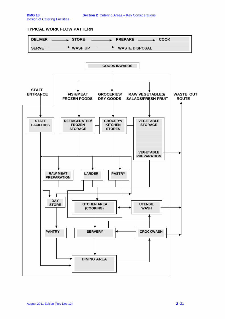
DMG 18 Section 2 Catering Areas – Key Considerations Design of Catering Facilities TYPICAL WORK FLOW PATTERN
DELIVER STORE PREPARE COOK SERVE WASH UP WASTE DISPOSAL
GOODS INWARDS STAFF ENTRANCE FISH/MEAT GROCERIES/ RAW VEGETABLES/ WASTE OUT FROZEN FOODS DRY GOODS SALADS/FRESH FRUIT ROUTE
STAFF FACILITIES
REFRIGERATED/ FROZEN
STORAGE
GROCERY/KITCHEN STORES
VEGETABLE STORAGE
VEGETABLE PREPARATION
LARDERRAW MEAT PREPARATION
PASTRY
KITCHEN AREA(COOKING)
UTENSIL WASH
PANTRY SERVERY CROCKWASH
DINING AREA
DAY STORE
August 2011 Edition (Rev Dec 12) 2 -21

DMG 18 Section 2 Catering Areas – Key Considerations Design of Catering Facilities 2.4 KITCHEN FUNCTION
The kitchen is the main hub of the facility. Its prime function is cooking and finishing of food prepared elsewhere within the facility and from where it is moved forward to the service area. LAYOUT CONSIDERATIONS Typical kitchen layouts are based on the equipment detailed in JSP 315, Scales 39 and 52, Part 4. The standard and specification of the equipment is detailed in DE Specification 42 – Catering Equipment Specification. Equipment should be laid out to make best use of the space available and provide a linear workflow from the preparation areas through to the servery. Kitchens should be planned with separation between the kitchen and the servery area but this can also be influenced by the style of service. Kitchens require a direct functional relationship with storage and preparation areas, servery and the utensil wash. The prime cooking equipment should be located, wherever possible, in an island setting. Similar types of equipment to be grouped together with sufficient worktop space placed adjacent to allow 'put-down' space. Heavy processes such as frying etc, should be grouped together. In larger kitchens the equipment (deep fat fryers, bratt pans, etc) may be sited in a separate suite, preferably in a central cooking suite rather than against a wall. Equipment providing long cooking processes such as ovens etc, need to be located furthest from the servery access whereas short order grills and ranges should be located nearby. All equipment should, where practicable, be mobile to facilitate cleaning and maintenance. Adequate space should be allowed to provide access for cleaning and to avoid damage to fabric and fittings. Sufficient equipment should be available to enable all of the kitchen operational tasks to be carried out in a safe and hygienic manner.
Back bar equipment may be installed within the kitchen to meet the Particular Specification. Service supplies of gas, water and electricity should rise or drop at one connection point to groups of equipment and contained within a service spine. In installations where a service spine is not practical, connections to equipment shall be not less than 300mm clear of the floor and the equipment sited not less than 150mm clear of the walls. Adequate floor drainage gullies should be installed to allow direct discharge from defined items of catering equipment and allow appropriate drainage to assist floor cleaning procedures.
August 2011 Edition (Rev Dec 12) 2 -22
DMG 18 Section 2 Catering Areas – Key Considerations Design of Catering Facilities
EQUIPMENT AND FITTINGS
See JSP 315, Scale 39, Part 4 & Scale 52; Annexes B & D
FINISHES AND SERVICES
See Section 7.
August 2011 Edition (Rev Dec 12) 2 -23

DMG 18 Section 2 Catering Areas – Key Considerations Design of Catering Facilities
2.5 CROCKERY WASH FUNCTION The crockery wash provides facilities for the receiving, sorting, washing, sterilisation and drying of all crockery, cutlery, glassware and trays after use in the dining room. Emphasis should be given to treating this area as a total integrated system. The detailed design shall take full account of the Energy Conservation Act 1981, the CIBSE Energy Code and current Building Regulations and shall include sufficient space for the provision and installation of all equipment necessary to comply with the requirements and recommendations. LAYOUT CONSIDERATIONS The siting of the crockwash is the most critical and difficult of the areas in planning terms because of the conflicting requirements.
• It should be sited so that there is direct access to the waste food storage/treatment area (to prevent cross contamination).
• Access from the dining areas with dirty plates should be such that they do not pass through the servery areas.
• Clean plates should not be contaminated by dirty plates and waste food. The equipment should be laid out to make best use of the space available and provide a workflow system to complement the determined method of clearance. Adequate ventilation and extraction shall be provided to ensure that steam emitted from the dishwasher does not give rise to condensation within the room. Consideration shall be given to the installation of a heat recovery system within the dishwasher to reduce the requirement for a dedicated extraction system to the dishwasher and provide an energy efficient system. Adequate floor drainage gullies should be installed to allow direct discharge from defined items of catering equipment and allow appropriate drainage to assist floor cleaning procedures. Systems shall be designed to ensure that adequate space is available to provide benching to accommodate the dropping off and processing of soiled items prior to entering the dishwasher. The ideal flow is receipt, scrapping, sorting and pre-wash prior to washing. The 'cleans' benching should be of sufficient size to allow crockery to air dry prior to stacking. Sufficient storage space is to be provided for clean items prior to being returned to the serveries and sideboards. This may include racking or mobile plate lowerators/trolleys. The location and layout of the crockery wash depends on whether:
Tables are cleared by staff either directly to the crockery wash or by the use of trolleys.
or Diners return their own dirties to the crockery wash.
It is very important that the designer receives a clear directive as to which system for table clearance is to be used by the unit. In both cases there should be direct access
August 2011 Edition (Rev Dec 12) 2 -24

DMG 18 Section 2 Catering Areas – Key Considerations Design of Catering Facilities
between the crockery wash and the servery area for the return of clean crockery, cutlery and trays. Table Clearance by Staff (see – Workflow within the Crockery Wash) The crockery wash should be sited adjacent to both the dining room and the servery to minimise the travel distance for the replenishment of crockery and cutlery to the servery and the sideboard(s) located in the dining room.
Where staff use trolleys to clear the tables, the crockery wash should cater for the receiving of loaded trolleys by provision of a parking space adjacent to the unloading/scrapping area.
Food is scraped into a suitable container and the dishes sorted prior to washing. Maceration could also include a de-watering process where the solids are collected separately in a container or bag and removed to the refuse area for collection.
Dishes that are heavily soiled are pre-rinsed using the pressure spray over the sinks.
Items for washing are loaded into racks and passed through the washing machine.
Clean items are allowed to dry before unloading from the racks. Plates are stored in lowerators or a bespoke transporter and all other items are returned to the servery or sideboard as required ready for re-use. Table Clearance by Diners (See – Workflow within the Crockery Wash) The crockery wash should be sited close to the dining room exit route to avoid unnecessary circulation within the dining area. Cross flows should be avoided.
Diners return their own dirty trays, crockery and cutlery either to bespoke clearing trolleys adjacent to the crockery wash or to a carousel/conveyor clearing system, depending on the NTBF. If a trolley system is used, then a parking space should be provided adjacent to the unloading/scraping area. The crockery wash system will follow the same system as for clearance by staff. Where NTBF are over 400, consideration may be given to the provision of a conveyor clearing system. The design of the crockery wash is crucial if this system is to be introduced. The designer should ensure that there is sufficient space both inside and adjacent to the crockery wash and that there will be sufficient labour to deal with the scraping, washing and stacking of crockery, etc, within the given meal period. The KDEA should be consulted at the Project Definition Stage.
August 2011 Edition (Rev Dec 12) 2 -25
DMG 18 Section 2 Catering Areas – Key Considerations Design of Catering Facilities
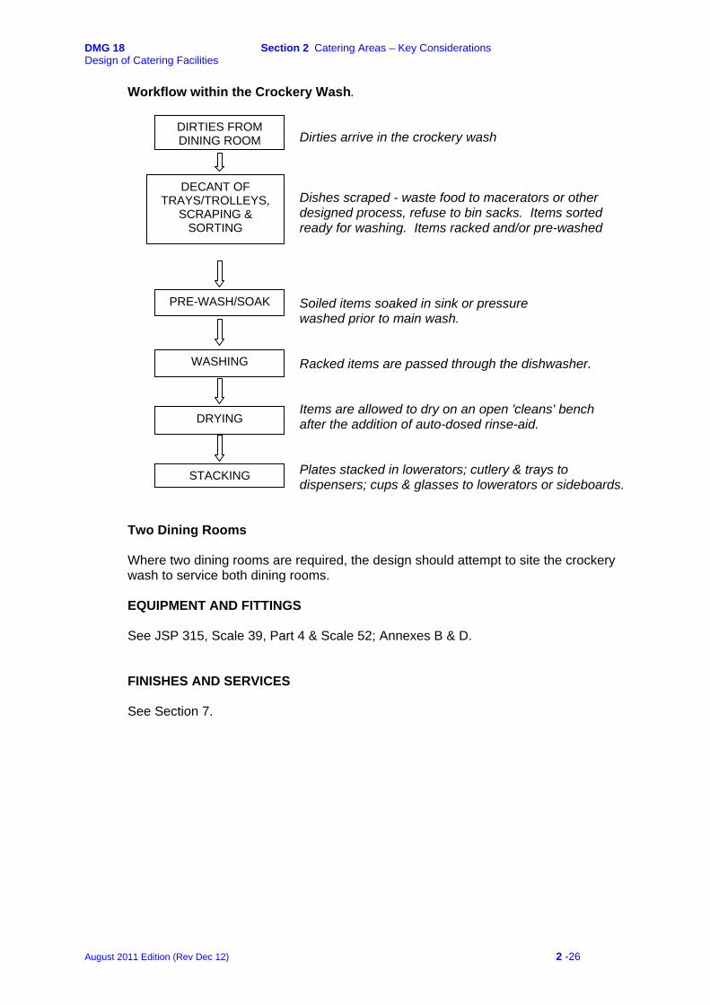
Workflow within the Crockery Wash.
Dirties arrive in the crockery wash
DIRTIES FROM DINING ROOM
DECANT OF
TRAYS/TROLLEYS, SCRAPING &
SORTING
Dishes scraped - waste food to macerators or other designed process, refuse to bin sacks. Items sorted ready for washing. Items racked and/or pre-washed
PRE-WASH/SOAK Soiled items soaked in sink or pressure washed prior to main wash.
Racked items are passed through the dishwasher. Items are allowed to dry on an open 'cleans' bench
WASHING
after the addition of auto-dosed rinse-aid. DRYING
Plates stacked in lowerators; cutlery & trays to dispensers; cups & glasses to lowerators or sideboards.
STACKING
Two Dining Rooms Where two dining rooms are required, the design should attempt to site the crockery wash to service both dining rooms.
EQUIPMENT AND FITTINGS See JSP 315, Scale 39, Part 4 & Scale 52; Annexes B & D. FINISHES AND SERVICES See Section 7.
August 2011 Edition (Rev Dec 12) 2 -26
DMG 18 Section 2 Catering Areas – Key Considerations Design of Catering Facilities
2.6 UTENSIL WASH FUNCTION
All cooking equipment from the kitchen area and the servery is washed at this location. This includes pots, pans, gastronorm service containers, utensils and parts from food preparation equipment. Waste food is either scraped into suitable containers prior to further treatment or disposed of in the waste disposal unit. Washed utensils, etc, are rinsed in hot water (>82°C) and left to drain dry prior to being stored on the storage racks.
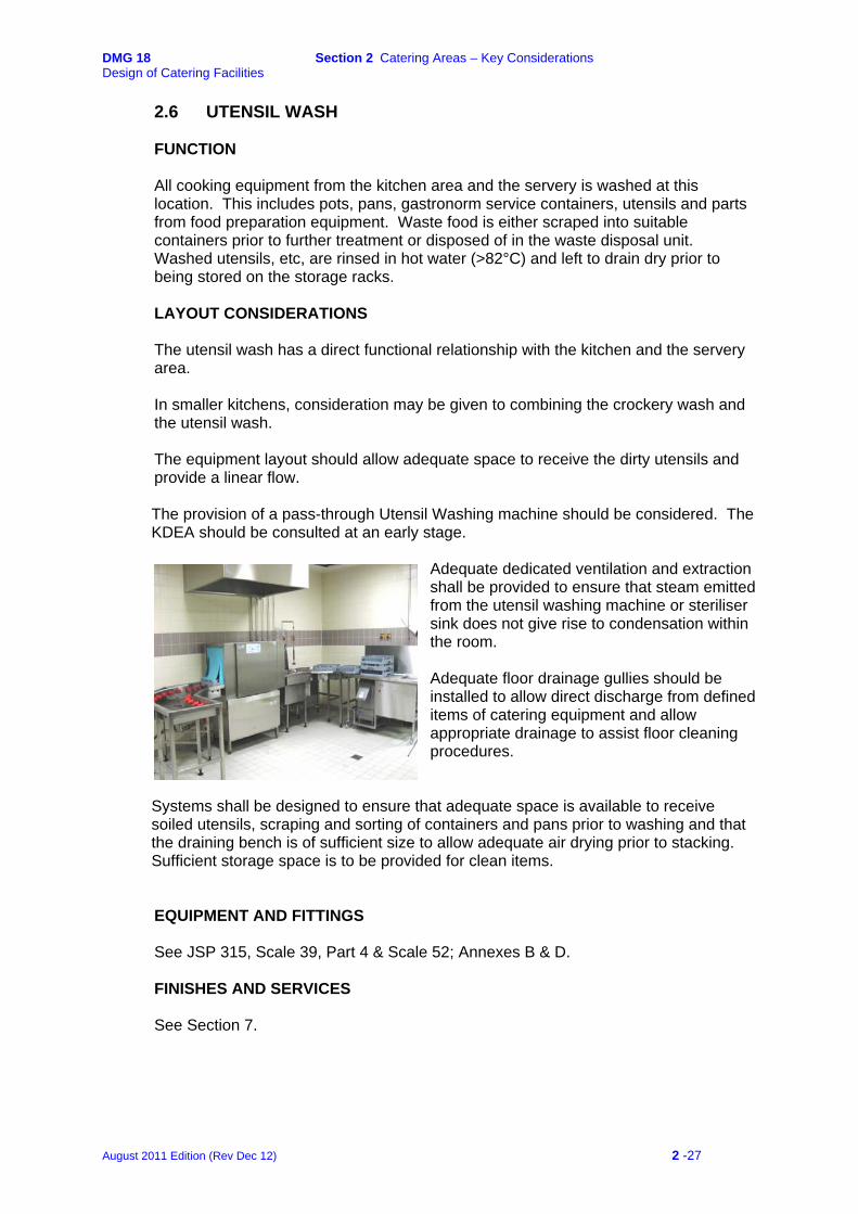
LAYOUT CONSIDERATIONS
The utensil wash has a direct functional relationship with the kitchen and the servery area. In smaller kitchens, consideration may be given to combining the crockery wash and the utensil wash. The equipment layout should allow adequate space to receive the dirty utensils and provide a linear flow. The provision of a pass-through Utensil Washing machine should be considered. The KDEA should be consulted at an early stage.
Adequate dedicated ventilation and extraction shall be provided to ensure that steam emitted from the utensil washing machine or steriliser sink does not give rise to condensation within the room.
Adequate floor drainage gullies should be installed to allow direct discharge from defined items of catering equipment and allow appropriate drainage to assist floor cleaning procedures.
Systems shall be designed to ensure that adequate space is available to receive soiled utensils, scraping and sorting of containers and pans prior to washing and that the draining bench is of sufficient size to allow adequate air drying prior to stacking. Sufficient storage space is to be provided for clean items.
EQUIPMENT AND FITTINGS See JSP 315, Scale 39, Part 4 & Scale 52; Annexes B & D. FINISHES AND SERVICES
See Section 7.
August 2011 Edition (Rev Dec 12) 2 -27
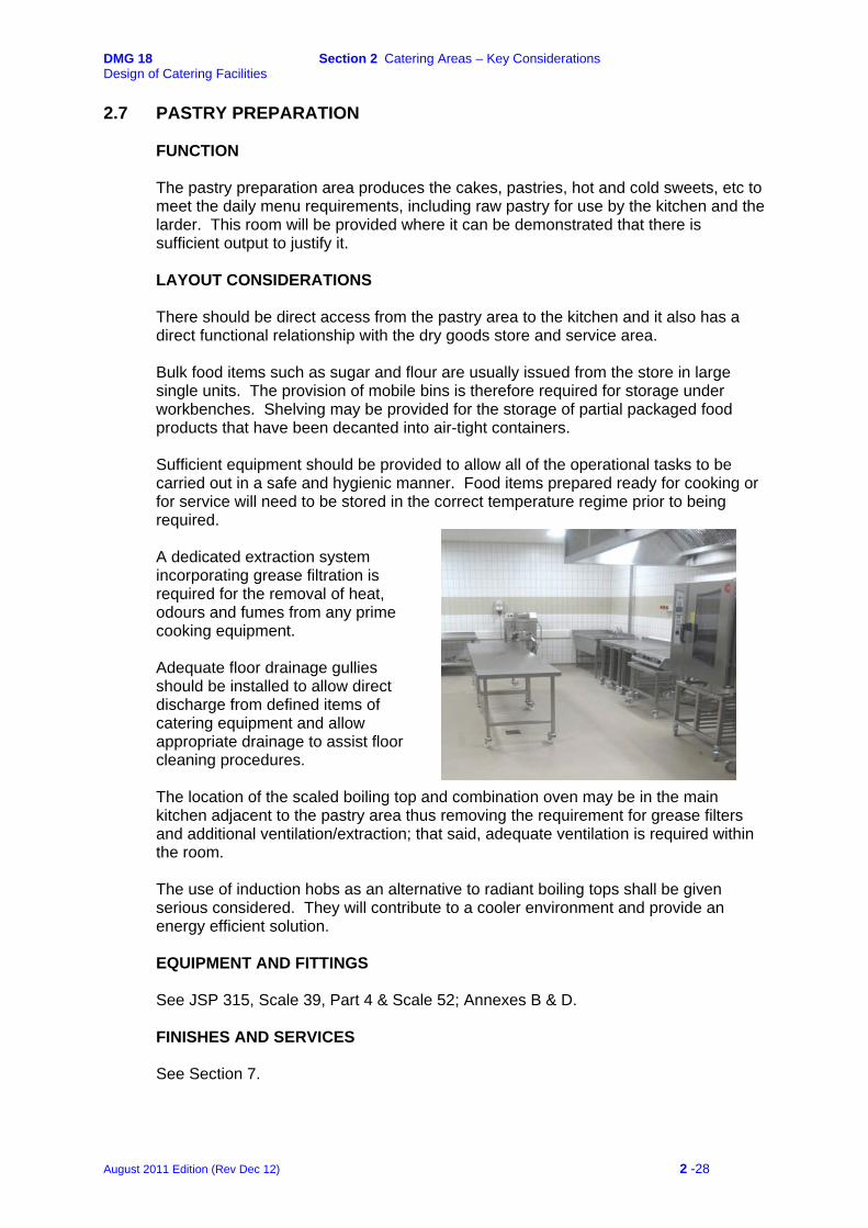
DMG 18 Section 2 Catering Areas – Key Considerations Design of Catering Facilities
2.7 PASTRY PREPARATION FUNCTION
The pastry preparation area produces the cakes, pastries, hot and cold sweets, etc to meet the daily menu requirements, including raw pastry for use by the kitchen and the larder. This room will be provided where it can be demonstrated that there is sufficient output to justify it.
LAYOUT CONSIDERATIONS
There should be direct access from the pastry area to the kitchen and it also has a direct functional relationship with the dry goods store and service area. Bulk food items such as sugar and flour are usually issued from the store in large single units. The provision of mobile bins is therefore required for storage under workbenches. Shelving may be provided for the storage of partial packaged food products that have been decanted into air-tight containers. Sufficient equipment should be provided to allow all of the operational tasks to be carried out in a safe and hygienic manner. Food items prepared ready for cooking or for service will need to be stored in the correct temperature regime prior to being required.
A dedicated extraction system incorporating grease filtration is required for the removal of heat, odours and fumes from any prime cooking equipment. Adequate floor drainage gullies should be installed to allow direct discharge from defined items of catering equipment and allow appropriate drainage to assist floor cleaning procedures. The location of the scaled boiling top and combination oven may be in the main kitchen adjacent to the pastry area thus removing the requirement for grease filters and additional ventilation/extraction; that said, adequate ventilation is required within the room. The use of induction hobs as an alternative to radiant boiling tops shall be given serious considered. They will contribute to a cooler environment and provide an energy efficient solution.
EQUIPMENT AND FITTINGS See JSP 315, Scale 39, Part 4 & Scale 52; Annexes B & D. FINISHES AND SERVICES
See Section 7.
August 2011 Edition (Rev Dec 12) 2 -28
DMG 18 Section 2 Catering Areas – Key Considerations Design of Catering Facilities
2.8 LARDER FUNCTION
The larder is the main food preparation area and should be considered as the area offering the highest risk in terms of food preparation and cross contamination. Where space is at a premium the raw meat preparation area may be included within the larder, however, strict separation of the work processes should be demonstrated.
LAYOUT CONSIDERATIONS
The larder has a direct functional relationship with the main kitchen, servery, storage and delivery areas. Sufficient equipment should be provided to allow all of the larder operational tasks to be carried out in a safe and hygienic manner. Food items prepared ready for cooking or service will need to be stored at the correct temperature regime until required. The room shall be self-contained and only designed as part of the Raw Meat Preparation to utilise a single air cooling facility where space is severely restricted. In all new build projects and the majority of refurbishments the larder and raw meat preparation areas shall be separate rooms. Where a combined room is the only option, the layout shall ensure the physical separation of areas for raw and cooked foods at all times with any dwarf wall separation being a minimum of 1800 mm above finished Floor Level (AFFL). Sufficient wash hand basins are to be provided and sited so as to ensure that there is no risk of cross contamination The area shall be provided with a dedicated wash hand basin. When high-risk operations are taking place, the temperature in the room is to be capable of being maintained at +13°C. Insulation, contained in vapour proof bags, shall be provided to the back of the ceiling tiles to prevent condensation; loose insulation is unacceptable.
Adequate floor drainage gullies should be installed to allow appropriate drainage to assist floor cleaning procedures.
EQUIPMENT AND FITTINGS See JSP 315, Scale 39, Part 4 & Scale 52; Annexes B & D. FINISHES AND SERVICES See Section 7.
August 2011 Edition (Rev Dec 12) 2 -29
DMG 18 Section 2 Catering Areas – Key Considerations Design of Catering Facilities
2.9 RAW MEAT PREPARATION FUNCTION
The Raw Meat Prep provides storage and preparation facilities for meat, poultry, fish and game, etc following delivery and prior to cooking. (See also Section 6)
LAYOUT CONSIDERATIONS
The raw meat prep has a direct functional relationship with the main kitchen, storage and delivery areas. It should be sited close to the loading/unloading area so as to reduce the risk of cross contamination. Sufficient equipment should be provided to allow all of the operational tasks to be carried out in a safe and hygienic manner. Adequate holding facilities will be required to keep prepared food in the correct temperature regime until required.
The room shall be self-contained and only designed as part of the Larder Preparation
to utilise a single air cooling facility where space is severely restricted. In all new build projects and the majority of refurbishments the larder and raw meat preparation areas shall be separate rooms. Where a combined room is the only option, the layout shall ensure the physical separation of areas for raw and cooked foods at all times with any dwarf wall separation being a minimum of 1800 mm above finished Floor Level (AFFL). Sufficient wash hand basins are to be provided and sited so as to ensure that there is no risk of cross contamination
The area shall be provided with a dedicated wash hand basin. When high-risk operations are taking place, the temperature in the room is to be capable of being maintained at +13°C. Insulation, contained in vapour proof bags shall be provided to the back of the ceiling tiles to prevent condensation; loose insulation is unacceptable.
Adequate floor drainage gullies should be installed to allow appropriate drainage to assist floor cleaning procedures.
EQUIPMENT AND FITTINGS See JSP 315, Scale 39, Part 4 & Scale 52; Annexes B & D. FINISHES AND SERVICES See Section 7.
August 2011 Edition (Rev Dec 12) 2 -30

DMG 18 Section 2 Catering Areas – Key Considerations Design of Catering Facilities
2.10 VEGETABLE PREPARATION AND STORAGE FUNCTION
All fresh vegetables, salads and fruit are received, stored and prepared in this area prior to being forwarded to the kitchen for cooking.
LAYOUT CONSIDERATIONS
The Vegetable Preparation Room has a direct functional relationship with the goods inwards area and the main kitchen. The room is predominately a wet area and mobile sinks are regularly used for the transport of prepared vegetables to the kitchen. A suitable potable cold water tap is required for filling the sinks. An adequate floor drain is required to empty the mobile sinks and provide for effective cleaning and wash down of the room. Equipment should be laid out to make best use of the space available and provide a linear storage and workflow from the preparation areas through to the kitchen. Sufficient equipment should be provided to allow all of the vegetable preparation tasks to be carried out in a safe and hygienic manner; noting that food is prepared ready for cooking and will need to be stored prior to being required.
The temperature in the room is to be capable of being controlled to ensure that it is not above +16°C. There are two distinct lines of preparation:
• Potato Storage and Preparation
Pre-washed potatoes are delivered and stored directly from the loading bay onto a potato platform. The potatoes are processed through potato peeling machine(s), after which they are discharged into a fabricated trough where they are hand-finished and temporarily stored in the mobile sink until required for cooking.
• Vegetable Storage and Preparation
Fresh fruit, greens and root vegetables are stored on mobile vegetable racks. Salad items are stored in a refrigerator.
In-line benching with a sink should be provided for the preparation of vegetables. Processes will include the use of a vegetable preparation machine, hand preparation and washing. Waste peelings etc are either deposited into suitable containers or macerated.
EQUIPMENT AND FITTINGS See JSP 315, Scale 39, Part 4 & Scale 52; Annexes B & D. FINISHES AND SERVICES
See Section 7.
August 2011 Edition (Rev Dec 12) 2 -31
DMG 18 Section 2 Catering Areas – Key Considerations Design of Catering Facilities
2.11 DAY STORE (KITCHEN FOOD STORE) FUNCTION
The kitchen food store provides storage facilities for food items required for the day-to-day running of the kitchen, pastry and larder departments. (See also - Grocery Store.)
KEY LAYOUT CONSIDERATIONS
The kitchen food store shall be sited within the kitchen area and near to the grocery store. Additionally, it should be in a cool area and not adjoining a calorifier, boiler or plant room where heat transfer through the walls and piping is likely. The room should be secured and be provided with a lockable door. Adequate ventilation shall be provided. Consideration may be given to combining the Day Store and Bulk Grocery Store to provide one large storage area where the administration for the issue of stores allows. The relevant KDEA should be consulted.
EQUIPMENT AND FITTINGS
See JSP 315, Scale 39, Part 4 & Scale 52; Annexes B & D. FINISHES AND SERVICES See Section 7.
2.12 KITCHEN EQUIPMENT STORE FUNCTION
This room provides storage facilities for spare kitchen equipment utensils and cooking pans that may not be in daily use.
LAYOUT CONSIDERATIONS
The store has a direct functional relationship with the main kitchen and the utensil wash. Where the NTBF does not exceed 200, this store may be combined with the Crockery, Glass and Linen Store (CGL). (See 4.4) Adequate ventilation shall be provided to prevent condensation.
EQUIPMENT AND FITTINGS
See JSP 315, Scale 39, Part 4 & Scale 52; Annexes B & D. FINISHES AND SERVICES See Section 7.
August 2011 Edition (Rev Dec 12) 2 -32
DMG 18 Section 2 Catering Areas – Key Considerations Design of Catering Facilities
2.13 BULK REFRIGERATION/FREEZER STORE FUNCTION
The Bulk Refrigeration/Freezer Store houses the main chilled and frozen food deliveries prior to issue to the other areas. (See also Section 6) LAYOUT CONSIDERATIONS
The room must be self-contained and capable of being secured.
It should be sited close to the loading/unloading area and the Catering Control Offices. Access should be wide enough to accept palletised deliveries where specified. The area shall be well ventilated and provide sufficient air changes capable of extracting heat given off from the refrigeration and freezer plant and meet the manufacturers recommendations for operating temperatures. Mechanical extraction shall be provided above refrigeration and deep freeze cabinets. Consideration may be given to the provision of walk-in modular refrigerators and freezers when the menu dictates a requirement for a large quantity of lighter, bulky items. The installation should meet the specifications included at DE Specification 42 – Catering Equipment Specification. Where tiled floors are adjacent to the installation, the floor finish should be continued into the walk in facilities. An under-floor heating system shall be provided within deep freeze installations where the tiled floor is continued into the modular section. Consult the KDEA for further advice. In smaller messes, consideration may be given to combining the room with the Bulk Grocery Store and Day Store to provide one large storage area where the administration for the issue of stores allows. The relevant KDEA should be consulted.
EQUIPMENT AND FITTINGS See JSP 315, Scale 39, Part 4 & Scale 52; Annexes B & D.
FINISHES AND SERVICES
See Section 7.
August 2011 Edition (Rev Dec 12) 2 -33
DMG 18 Section 2 Catering Areas – Key Considerations Design of Catering Facilities
2.14 BULK GROCERY STORE FUNCTION
The Grocery Store receives and issues the full range of food commodities. (See also Section 6) LAYOUT CONSIDERATIONS
The room must be self-contained and capable of being secured.
It shall be sited close to the loading/unloading area and the Catering Control Offices. Access to the store and the gangways within shall be wide enough to accept palletised deliveries. The area must be well ventilated and provide sufficient air changes capable of extracting heat given off from any refrigeration and freezer plant and be temperature controlled within the range of 12°C – 16°C. Insulation, contained in vapour proof bags shall be provided to the back of the ceiling tiles to prevent condensation, loose insulation is unacceptable. Consideration may be given to combining the Bulk Grocery Store and Day Store to provide one large storage area where the administration for the issue of stores allows. The relevant KDEA should be consulted.
EQUIPMENT AND FITTINGS See JSP 315, Scale 39, Part 4 & Scale 52; Annexes B & D.
FINISHES AND SERVICES
See Section 7.
August 2011 Edition (Rev Dec 12) 2 -34
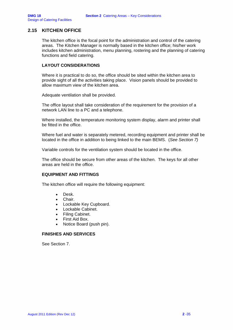
DMG 18 Section 2 Catering Areas – Key Considerations Design of Catering Facilities
2.15 KITCHEN OFFICE
The kitchen office is the focal point for the administration and control of the catering areas. The Kitchen Manager is normally based in the kitchen office; his/her work includes kitchen administration, menu planning, rostering and the planning of catering functions and field catering.
LAYOUT CONSIDERATIONS
Where it is practical to do so, the office should be sited within the kitchen area to provide sight of all the activities taking place. Vision panels should be provided to allow maximum view of the kitchen area. Adequate ventilation shall be provided. The office layout shall take consideration of the requirement for the provision of a network LAN line to a PC and a telephone. Where installed, the temperature monitoring system display, alarm and printer shall be fitted in the office. Where fuel and water is separately metered, recording equipment and printer shall be located in the office in addition to being linked to the main BEMS. (See Section 7) Variable controls for the ventilation system should be located in the office. The office should be secure from other areas of the kitchen. The keys for all other areas are held in the office.
EQUIPMENT AND FITTINGS
The kitchen office will require the following equipment:
• Desk. • Chair. • Lockable Key Cupboard. • Lockable Cabinet. • Filing Cabinet. • First Aid Box. • Notice Board (push pin).
FINISHES AND SERVICES See Section 7.
August 2011 Edition (Rev Dec 12) 2 -35
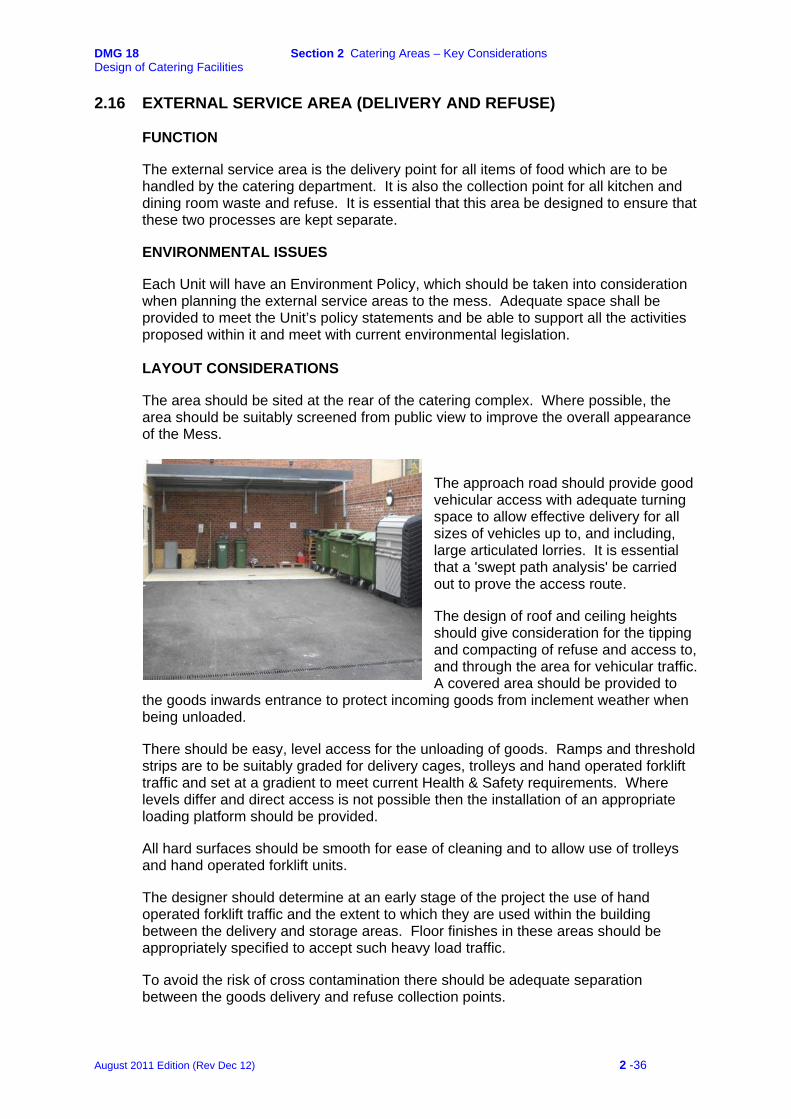
DMG 18 Section 2 Catering Areas – Key Considerations Design of Catering Facilities
2.16 EXTERNAL SERVICE AREA (DELIVERY AND REFUSE) FUNCTION
The external service area is the delivery point for all items of food which are to be handled by the catering department. It is also the collection point for all kitchen and dining room waste and refuse. It is essential that this area be designed to ensure that these two processes are kept separate.
ENVIRONMENTAL ISSUES
Each Unit will have an Environment Policy, which should be taken into consideration when planning the external service areas to the mess. Adequate space shall be provided to meet the Unit’s policy statements and be able to support all the activities proposed within it and meet with current environmental legislation.
LAYOUT CONSIDERATIONS
The area should be sited at the rear of the catering complex. Where possible, the area should be suitably screened from public view to improve the overall appearance of the Mess.
The approach road should provide good vehicular access with adequate turning space to allow effective delivery for all sizes of vehicles up to, and including, large articulated lorries. It is essential that a 'swept path analysis' be carried out to prove the access route.
The design of roof and ceiling heights should give consideration for the tipping and compacting of refuse and access to, and through the area for vehicular traffic. A covered area should be provided to
the goods inwards entrance to protect incoming goods from inclement weather when being unloaded. There should be easy, level access for the unloading of goods. Ramps and threshold strips are to be suitably graded for delivery cages, trolleys and hand operated forklift traffic and set at a gradient to meet current Health & Safety requirements. Where levels differ and direct access is not possible then the installation of an appropriate loading platform should be provided. All hard surfaces should be smooth for ease of cleaning and to allow use of trolleys and hand operated forklift units. The designer should determine at an early stage of the project the use of hand operated forklift traffic and the extent to which they are used within the building between the delivery and storage areas. Floor finishes in these areas should be appropriately specified to accept such heavy load traffic. To avoid the risk of cross contamination there should be adequate separation between the goods delivery and refuse collection points.
August 2011 Edition (Rev Dec 12) 2 -36
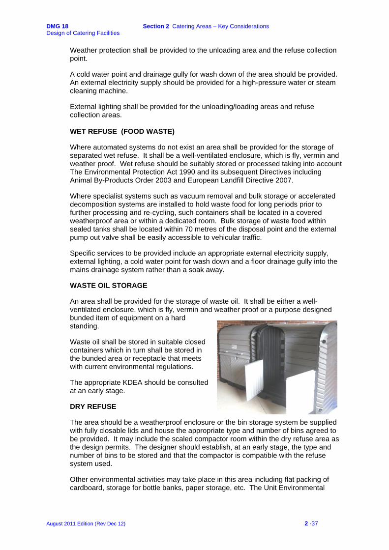
DMG 18 Section 2 Catering Areas – Key Considerations Design of Catering Facilities
Weather protection shall be provided to the unloading area and the refuse collection point. A cold water point and drainage gully for wash down of the area should be provided. An external electricity supply should be provided for a high-pressure water or steam cleaning machine. External lighting shall be provided for the unloading/loading areas and refuse collection areas.
WET REFUSE (FOOD WASTE)
Where automated systems do not exist an area shall be provided for the storage of separated wet refuse. It shall be a well-ventilated enclosure, which is fly, vermin and weather proof. Wet refuse should be suitably stored or processed taking into account The Environmental Protection Act 1990 and its subsequent Directives including Animal By-Products Order 2003 and European Landfill Directive 2007. Where specialist systems such as vacuum removal and bulk storage or accelerated decomposition systems are installed to hold waste food for long periods prior to further processing and re-cycling, such containers shall be located in a covered weatherproof area or within a dedicated room. Bulk storage of waste food within sealed tanks shall be located within 70 metres of the disposal point and the external pump out valve shall be easily accessible to vehicular traffic. Specific services to be provided include an appropriate external electricity supply, external lighting, a cold water point for wash down and a floor drainage gully into the mains drainage system rather than a soak away. WASTE OIL STORAGE An area shall be provided for the storage of waste oil. It shall be either a well-ventilated enclosure, which is fly, vermin and weather proof or a purpose designed bunded item of equipment on a hard standing. Waste oil shall be stored in suitable closed containers which in turn shall be stored in the bunded area or receptacle that meets with current environmental regulations.
The appropriate KDEA should be consulted at an early stage. DRY REFUSE
The area should be a weatherproof enclosure or the bin storage system be supplied with fully closable lids and house the appropriate type and number of bins agreed to be provided. It may include the scaled compactor room within the dry refuse area as the design permits. The designer should establish, at an early stage, the type and number of bins to be stored and that the compactor is compatible with the refuse system used.
Other environmental activities may take place in this area including flat packing of cardboard, storage for bottle banks, paper storage, etc. The Unit Environmental
August 2011 Edition (Rev Dec 12) 2 -37
DMG 18 Section 2 Catering Areas – Key Considerations Design of Catering Facilities
Policy should be consulted to determine the use and spatial requirements for the area and appropriate services be provided accordingly.
Specific services to be provided include an appropriate external electricity supply for a compactor, external lighting, a cold water point for wash down and a floor drainage gully into the mains drainage system rather than a soak away.
The ceiling height should take into account the operating parameters of a compactor.
EQUIPMENT AND FITTINGS
See JSP 315; Scale 39, Part 4 & Scale 52; Annexes B & D.
FINISHES AND SERVICES See Section 7.
2.17 CLEANERS ROOM See Section 4.5. 2.18 NORWEGIAN CONTAINER WASH (where provided) FUNCTION
Where there is a requirement to provide Norwegian containers on a regular basis, a Norwegian Container Wash room may be provided for the washing and storage of the containers. LAYOUT CONSIDERATIONS The room has a direct functional relationship with the external delivery area and the utensil wash. The location should enable receipt of dirty Norwegian containers direct from the 'field' to be emptied and washed without entering a food room. After washing, the process would enable the containers to be further washed and sterilised in the utensil wash before being stored ready for use. Adequate floor drainage gullies should be installed to allow direct discharge from defined items of catering equipment and allow appropriate drainage to assist floor cleaning procedures. See JSP 315, Scale 39, Part 2, Serial 32.
EQUIPMENT AND FITTINGS
See JSP 315; Scale 39, Part 4& Scale 52; Annexes B & D.
FINISHES AND SERVICES See Section 7
August 2011 Edition (Rev Dec 12) 2 -38
DMG 18 Section 2 Catering Areas – Key Considerations Design of Catering Facilities
2.19 PACKED MEAL ROOM (where provided) FUNCTION
Where there is a requirement to provide a large amount of packed meals on a regular basis, a room may be provided for the assembly and storage of meals, filled rolls or sandwiches required for collection. LAYOUT CONSIDERATIONS The room has a direct functional relationship with the external delivery area and/or the Servery and should be located to allow the collection of packed meals by individuals or groups without accessing the catering area. The area should be treated with the same considerations as for the Larder at 2.8 and may be co-located with that facility according to the design considerations. EQUIPMENT AND FITTINGS See JSP 315; Scale 39, Part 4& Scale 52; Annexes B & D.
FINISHES AND SERVICES See Section 7.
August 2011 Edition (Rev Dec 12) 2 -39

DMG 18 Section 3 Servery Design of Catering Facilities
3
Servery SECTION 3 SERVERY
3.1 SERVERY 3.2 BACK BAR & FRONT OF HOUSE COOKING 3.3 PANTRY 3.4 SIDEBOARD 3.5 ENTRANCE LOBBY AND QUEUE SPACE 3.6 CLOAKS AND TOILETS
August 2011 Edition (Rev Dec 12) 3 -40

DMG 18 Section 3 Servery Design of Catering Facilities
3 Servery 3.1 SERVERY FUNCTION
The servery is the focal point for the service of all meals. The layout will be dictated by a number of interacting factors including:
NTBF The meal period(s). The required speed of diner throughput (service density). The structural shape and required flow patterns of the servery area. The type of unit. The type of menu(s) to be served. Point of Sale Finishing (front of house cooking) Catering Retail & Leisure (CRL) considerations including circulation, retail opportunities, and payment points. Compatibility with Front of House facilities under Scale 52 provisions.
LAYOUT CONSIDERATIONS
The servery has a direct functional relationship with the main kitchen, dining room, crockwash and the pantry and, to a lesser degree, the utensil wash. The layout should be designed to minimise the cross flow of both staff and diners. The servery should be planned for either self-service or staffed service for the 3 meals daily or through the day service according to the particular requirements. The areas given in JSP 315, Scale 39, Parts 3a and 3b and Scale 52 allow for the circulation of both staff and diners. Where a cafeteria type service is offered involving the customers approaching the servery counter displays directly, a full-height solid wall should separate the servery and kitchen. Access doors should be wide enough to ensure the safe movement of staff who may be carrying hot food. The doors should be capable of being held open (electronically) during the service period or swing through 180°, with a dedicated in/out traffic flow. Where a full steward service is offered the servery may form part of the kitchen fitted out with a suitable ‘service pass’. The layout of the service counters should provide for the required number of diners to be served and have completed their meal within the given meal period. Flow patterns and the number of service points will need to account for service density and speed of throughput. Equally, each service point should be positioned to allow hot and cold foods to be brought from the kitchen areas directly to the counters speedily and avoiding safety hazards. Hot counters should be placed as close to the kitchen as possible.
August 2011 Edition (Rev Dec 12) 3 -41
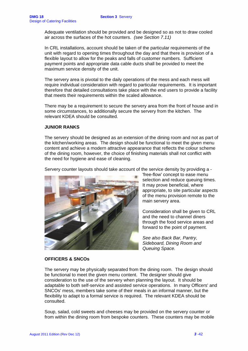
DMG 18 Section 3 Servery Design of Catering Facilities
Adequate ventilation should be provided and be designed so as not to draw cooled air across the surfaces of the hot counters. (see Section 7.11) In CRL installations, account should be taken of the particular requirements of the unit with regard to opening times throughout the day and that there is provision of a flexible layout to allow for the peaks and falls of customer numbers. Sufficient payment points and appropriate data cable ducts shall be provided to meet the maximum service density of the unit. The servery area is pivotal to the daily operations of the mess and each mess will require individual consideration with regard to particular requirements. It is important therefore that detailed consultations take place with the end users to provide a facility that meets their requirements within the scaled allowance. There may be a requirement to secure the servery area from the front of house and in some circumstances, to additionally secure the servery from the kitchen. The relevant KDEA should be consulted. JUNIOR RANKS The servery should be designed as an extension of the dining room and not as part of the kitchen/working areas. The design should be functional to meet the given menu content and achieve a modern attractive appearance that reflects the colour scheme of the dining room, however, the choice of finishing materials shall not conflict with the need for hygiene and ease of cleaning. Servery counter layouts should take account of the service density by providing a -
'free-flow' concept to ease menu selection and reduce queuing times. It may prove beneficial, where appropriate, to site particular aspects of the menu provision remote to the main servery area.
Consideration shall be given to CRL and the need to channel diners through the food service areas and forward to the point of payment.
See also Back Bar, Pantry, Sideboard, Dining Room and Queuing Space.
OFFICERS & SNCOs The servery may be physically separated from the dining room. The design should be functional to meet the given menu content. The designer should give consideration to the use of the servery when planning the layout. It should be adaptable to both self-service and assisted service operations. In many Officers' and SNCOs' mess, members take some of their meals in an informal manner, but the flexibility to adapt to a formal service is required. The relevant KDEA should be consulted. Soup, salad, cold sweets and cheeses may be provided on the servery counter or from within the dining room from bespoke counters. These counters may be mobile
August 2011 Edition (Rev Dec 12) 3 -42

DMG 18 Section 3 Servery Design of Catering Facilities
and may be made up from an element of the servery counter provision. The finishes and fabric should reflect those in the public areas. The relevant KDEA should be consulted. Care must be taken to avoid noise penetration from the servery and adjacent areas into the dining room. This is particularly important during formal functions when a steward service is in operation. Doors between the servery and the front of house shall be of sufficient width and design to allow the passage of a standard hot servery counter, allowing flexibility of service throughout the mess. Consideration shall be given to CRL. The systems of control and payment shall be taken into account during the design of the servery. The relevant KDEA should be consulted. See also Back Bar, Pantry and Sideboard.
3.2 BACK BAR & FRONT OF HOUSE (THEATRE) COOKING
A back bar and other direct cook to order provision may be installed in the servery or adjacent areas to provide an additional call order point of service. It shall be:
• capable of providing an element of front of house cooking supported by chilled and frozen storage and operating independently out of standard core service hours based on the service density as required by the unit.
• supported by a stand-alone point of sale facility fitted with the appropriate data
cabling ductwork.
• capable of providing catering for reduced numbers and negate the need to use the main kitchen equipment, thus reducing energy consumption.
Back bar equipment detailed in JSP 315, Scale 39 and 52, is normally located to the rear of, adjacent to or within a servery counter. Units shall be supplied and installed as described in Specification 42–Catering Equipment Specification, Serial 30, or the Particular Specification. Additional items of equipment may be added according to the Mess' requirements; these may include specific specialised items sited within the servery counters to meet the Particular Specification. It is important that the M & E design reflects these requirements during the design process. No gas fired equipment shall be installed in this area. Where the installation includes equipment such as deep fat fryer, bratt pan, char-grill or other intense heat cooking equipment, a suitable fire suppression system must be provided to cover the equipment in question. The system must be automatically operated and be provided with the facility to operate manually in case of emergency. The operation of this system should be linked in such a manner that its operation closes off the power to the equipment. The back bar cooking equipment must be served by a suitable ventilation system that meets the requirements of Crown Fire Standards, Para. 4.10 of Standard E5 refers. (see also Section 7.11)
August 2011 Edition (Rev Dec 12) 3 -43

DMG 18 Section 3 Servery Design of Catering Facilities
Back bar equipment shall be wired to its own individual isolator. Each isolator shall be wired to a single isolator located in an easily accessible location for use in an emergency. The back bar shall be capable of being totally isolated at a remote location within a secure area to prevent unauthorised use of the equipment.
3.3 PANTRY
A dedicated Pantry is only to be provided to Training Units where the Sideboards are located within the dining room, forward of the servery and within Officers’ and SNCOs’ messes. Where CRL systems operate, the area formerly allocated to the Pantry within the JSP scales is incorporated into the Servery area to provide the beverage counter facility.
See Section 4.2. 3.4 SIDEBOARD
A dedicated Sideboard is only to be provided to Training Units where there is a requirement for beverages and ancillary items to be located within the dining room, forward of the servery. Sideboards may also be provided within Officers’ and SNCOs’ messes according to the particular unit’s requirements. See Section 4.3.
3.5 ENTRANCE LOBBY AND QUEUE SPACE
FUNCTION
To provide entry to the Servery and Dining Room with access to the Toilets. Note: This section and JSP 315, Scales 39 & 52, Part 3a, apply only to Junior Ranks. For Officers and SNCOs, see JSP 315, Scales 29 and 34.
LAYOUT CONSIDERATIONS
The area should be sited to give easy access to the Servery, Toilets and Dining Room without causing cross flows of customers. The entrance should be well protected from the weather with a set of doors leading into a draught lobby and a further set of doors leading into the queue space within the servery or dining room.
If the Entrance Hall leads directly from the outside, a substantial heavy-duty mat area should be provided immediately inside the doors to the full width of the entrance. The designer should consider the type of floor surface to be provided and the need for drainage in light of the volume of numbers to be catered for. Where a Mess is particularly busy, with customers entering directly from 'field’ activities, the provision of shoe scrapers located outside and a floor gully for ease of cleaning may be considered. The particular design will need to consider CRL facilities according to the specific requirements. This may include adjacent or inclusive retail and leisure space as a complete complex as defined in JSP 315, Scale 52.
August 2011 Edition (Rev Dec 12) 3 -44
DMG 18 Section 3 Servery Design of Catering Facilities
QUEUE SPACE
The areas are given in JSP 315, Scale 39, Part 3a.
The Queue space may be aggregated. See JSP 315, Scale 39, Part 3a. Dependent on the position of the Dining Room to the living accommodation and other buildings, the Queue Space may be provided in the form of a covered area between adjoining buildings, adjacent retail area or included within the Dining Room itself. The space need not be planned as a single line queue situation but as an area where diners can assemble out of the cold and wet whilst awaiting access to the servery. The scale provides for a maximum queue time of 10 minutes. With the advent of CRL, the need to provide space for diners prior to reaching the various servery counters and exiting from the food service area through to the point of payment, is important. The designer will need to consider how the space is allocated and where it is located to provide sufficient flexibility to provide an efficient flow of diners within the desired time scale. EQUIPMENT AND FITTINGS See JSP 315, Scales 39, Parts 3a, 4a and 4b & Scale 52, Annexes B & D FINISHES AND SERVICES See Section 7.
3.6 TOILETS FUNCTION To provide toilet facilities for Junior Ranks.
Note: This section and JSP315, Scale 39, Part 3a, apply only to Junior Ranks. For Officers and SNCOs, see JSP 315, Scales 29 and 34.
LAYOUT CONSIDERATIONS
See JSP 315, Scales 39, Parts 4a and 4b & Scale 52 Part.3, Ser: 45 & Part 4, Ser: 64 To be sited for ease of access from the entrance Lobby, Queue Space and Dining Room on entry and exit. The facilities shall be provided in accordance with JSP 315, Scale 39, Part 3a. Additional space and facilities may need to be considered for the temporary storage of baggage where there is a requirement to feed diners who would be attending the Dining Room either directly prior to or after field exercises. The KDEA should be consulted at an early stage. Disabled facilities shall be so designed to comply with all current legislation, including Health and Safety, Disability Discrimination Act, Building Regulations, British Standards, European Normalisation and Codes of Practice.
August 2011 Edition (Rev Dec 12) 3 -45
DMG 18 Section 3 Servery Design of Catering Facilities
EQUIPMENT AND FITTINGS See JSP 315, Scale 52 Part.3, Ser: 45 & Part 4, Ser: 64
FINISHES AND SERVICES See Section 7.
August 2011 Edition (Rev Dec 12) 3 -46
DMG 18 Section 4 Dining Room Design of Catering Facilities
4
Dining Room SECTION 4 DINING ROOM
4.1 DINING AREA
4.2 PANTRY
4.3 SIDEBOARD
4.4 CROCKERY, GLASS AND LINEN STORE
4.5 CLEANERS ROOM
August 2011 Edition (Rev Dec 12) 4 -47
DMG 18 Section 4 Dining Room Design of Catering Facilities
4 Dining – Junior Ranks 4.1 DINING AREA FUNCTION The locations in which Junior Ranks’ meals are taken.
Note: This section and JSP315, Scale 39, Part 3a and Scale 52 applies only to Junior Ranks.
LAYOUT CONSIDERATIONS
The Dining Room should be sited to create a pleasant ambience. All meals are self-service therefore the layout will need to consider the flow of customers through the entrance and queuing space to the servery, the collection of incidentals en route to their seats and the clearing system on completion of the meal. Cross flows should be avoided. The final layout will be influenced by decisions taken on other aspects within the planning of the facility including:
The location of the Entrance. The positioning and practical use of the Queuing Space. Whether the area is for trained or trainee units or a combination of both. The relationship with other areas of retail activity provided under Scale 52. The provision of Toilets and Cloaks space. The location of the crockwash and the type of clearance. (See Section 2.5)
Every effort shall be made to reduce noise and glare by use of appropriate finishes and decor to create an ambience where meals may be taken. The number of seats and the area required for the Dining Room shall be calculated in accordance with JSP 315, Scale 39, Part 3a. and Scale 52. Large dining rooms should be sub-divided using screens or planters to create a more comfortable and discreet dining environment. These areas will relate to the servery capacities, service density within the meal period and PAYD implications. SPATIAL ALLOCATION
The designer should allow for the planning of primary and secondary circulation routes and also allow flexibility of plan form. Spaced zones should allow for adequate circulation space around the positioning of structural components, furniture and the provision of screens and planters. The spatial allocation may be increased if there are obstructions such as lifts or service ducts; the relevant KDEA should be consulted. EQUIPMENT AND FITTINGS See JSP 315, Scale 39, Part 3a.and Scale 52, Part 3, Serial 43a & Part 4, Serial 55a.
August 2011 Edition (Rev Dec 12) 4 -48

DMG 18 Section 4 Dining Room Design of Catering Facilities
FINISHES AND SERVICES See Section 7.
4.2 PANTRY
A dedicated Pantry is only to be provided to Training Units where the Sideboards are located within the dining room, forward of the servery. Where PAYD systems operate the area formerly allocated to the Pantry within the JSP scales is incorporated into the Servery area to provide the beverage counter facility.
4.3 SIDEBOARD
A dedicated Sideboard is only to be provided to Training Units where there is a requirement for beverages and ancillary items to be located within the dining room, forward of the servery. Where CRL systems operate, the area formerly allocated to the Pantry, which included the provision of the sideboard, within the JSP scales is incorporated into the Servery area to provide the beverage and ancillary products counter facilities.
LAYOUT CONSIDERATIONS
For Training Units the sideboards are located in the Dining Room and sited appropriately to allow diners the minimum travel distance to obtain ancillary items to their meal. Additionally they are to be sited to create a flow pattern so as to avoid a cross flow of foot traffic with the servery and where appropriate, the clearing area to the crockwash. Each sideboard will house the facilities to provide the ancillary items of food necessary to a meal and may include hot and cold beverages, bread and toast, etc. This will require the provision of essential items of equipment to provide a self-service operation including hot beverage machine, conveyor toaster, cup and glass storage, squash unit, milk dispenser and storage under. Adequate ventilation shall be provided. Where equipment is installed that will generate heat, fumes or steam, a dedicated ventilation system shall be installed with the mechanical extraction within a canopy sited immediately above the relevant items of equipment. Each sideboard will require the appropriate services to provide an adequate power supply, potable water supply and drainage. The detail of the design and specification is as described in Specification 42 – Catering Equipment Specification, Serial 36.
Services to sideboards shall be provided and designed so that all connections are concealed from view when the sideboards are removed. EQUIPMENT AND FITTINGS
See JSP 315, Scales 39, Parts 4a and 4b.
August 2011 Edition (Rev Dec 12) 4 -49

DMG 18 Section 4 Dining Room Design of Catering Facilities
FINISHES AND SERVICES
See Section 7. 4.4 CROCKERY, GLASS AND LINEN STORE
FUNCTION
The Crockery, Glass and Linen Store (CGL) provides storage facilities for spare crockery, glass and linen. It is not intended for the storage of items in daily use.
LAYOUT CONSIDERATIONS
The CGL should be sited adjacent to the Dining Room, the Servery and the Crockwash, with easy access from all areas where practicable.
For Junior Ranks, the CGL may be combined with the Kitchen Equipment Store where the NTBF does not exceed 300.
EQUIPMENT AND FITTINGS
See JSP 315, Scales 39, Parts 4a and 4b. FINISHES AND SERVICES
See Section 7 4.5 CLEANERS ROOM FUNCTION
The Cleaners Storeroom is used for the storage of the day-to-day cleaning materials and equipment such as brooms, buckets, mops, floor cleaning machine, power washer, etc.
LAYOUT CONSIDERATIONS
Provision is to be made for the filling and emptying of buckets, the washing and rinsing of mops, etc, remote from food preparation and dining areas. A rack is to be supplied on which to hang mops and brushes subsequent to washing. Wall protection is required to prevent damage to the wall in the local area.
To comply with 'Control of Substances Hazardous to Health' (COSHH) provision should be made for the bulk storage of chemicals for dishwashers, cleaning materials, etc, where not provided elsewhere in the building. These materials should be kept secure from the day-to-day requirements. (See JSP 315, Scale 39, Part 2.) Where the Cleaners Room is remote and not adjacent to a wash hand basin, a wash hand basin shall be provided as defined in JSP 315, Scale 1, Annex B, Serial 2; this may be integral with the bucket sink.
EQUIPMENT AND FITTINGS
See JSP 315, Scales 39, Part 4.
August 2011 Edition (Rev Dec 12) 4 -50
DMG 18 Section 4 Dining Room Design of Catering Facilities
FINISHES AND SERVICES
See Section 7
August 2011 Edition (Rev Dec 12) 4 -51

DMG 18 Section 5 Staff Facilities Design of Catering Facilities
5
Staff Facilities SECTION 5 STAFF FACILITIES
5.1 STAFF FACILITIES
August 2011 Edition (Rev Dec 12) 5 -51
DMG 18 Section 5 Staff Facilities Design of Catering Facilities
5.1 STAFF FACILITIES
FUNCTION
Accommodation and changing facilities for daily employed service and civilian catering staff that are required to change from outdoor clothing to protective work wear.
Staff facilities shall include space for the following:
• Changing/locker rooms. • Showers. • Toilets and washing. • Rest Room. • Female Rest Room.
LAYOUT CONSIDERATIONS
Staff facilities shall be located in a self-contained suite of rooms. The location should provide a separate entrance from the kitchen goods in and waste out routes and ensure direct separate access to both the catering area and the public areas.
Natural light should be provided and all areas shall be adequately ventilated.
Separate shower, changing/locker rooms shall normally be provided for male and female staff. Alternatively, consideration may be given to the provision of a single locker room with adjacent separate changing, shower and toilet facilities. The KDEA should be consulted.
Showers and toilets shall have direct access from the changing/locker room(s). See JSP 315, Scale 40 for additional information.
A Staff Rest Room shall be provided. A Female Rest Room shall be provided to comply with Workplace (Health, Safety and Welfare) Regulations. This room should be suitably located (e.g. near to the toilets) and should provide appropriate facilities for an unwell person to lie down. Where there is a first aid room with a bed within reasonable distance, this may be taken to satisfy the requirement. The requirement should be decided at the project brief stage. See JSP 315, Scale 47. Determination Application Part M – Access to and use of buildings of the Building Regulations 2010 (as amended) requires that where sanitary conveniences are to be provided on newly created and some refurbishment projects, accessible facilities should be provided also. As discussed in the introduction it is considered that anyone employed to work in the kitchen environment will be physically able bodied. This brings about a conflict in terms of the end user and compliance with mandatory legislation which, historically, has resulted in an application for determination of the Building Regulations to the Building Standards Team (BST) within Defence Infrastructure Organisation (DIO) who are the Technical Authority for Building Regulations on the Defence estate.
August 2011 Edition (Rev Dec 12) 5 -52
DMG 18 Section 5 Staff Facilities Design of Catering Facilities
Invariably this has led to differing standards of provision across the estate. The aim of this section is to set out what is considered an acceptable level of accessible provision of sanitary convenience in this environment to ensure value for money and consistency of design for future kitchen projects. An application for determination to DIO BST will need to be made to allow consideration for any future policy and legislative changes. After consultation with DIO BST the following provisions are considered acceptable and a determination would be granted on submission of a determination application. An accessible WC designed in accordance with diagram 18 contained in Approved Document M does need to be provided for use by back of house kitchen staff. Due consideration should be given to the location of the WC in relation to the distance from kitchen staff ablution areas and the access route from the kitchen area to the WC. An accessible Shower designed in accordance with diagram 23 contained in Approved Document M does not need to be provided. Where the kitchen and ancillary accommodation is provided over two floors a passenger lift does not need to be provided where the accessible WC and staff rest room has been provided as part of the ground floor accommodation and the staircase is designed to accommodate ambulant disabled users in accordance with the provisions laid out in 3.51 of Approved Document M. Where an accessible WC and/or a staff rest room is provided on the first floor a lift should be provided. For any further information please contact the DIO BST: Tel: 0121 311 2135/2013/2003. EQUIPMENT AND FITTINGS Lockers shall be provided for each member of staff employed. This may be greater than the staffing establishment of the unit due to 'job share' for instance. (The MOD normally provides these). Space for lockers shall be provided for the standard issue 'Food Handlers Locker' which is dimensioned at 450mm wide x 600mm deep x 1705mm high. A layout indicating the location and number of lockers is required to demonstrate that the correct number can be fitted within the location. See JSP 315 Scales 39, Part 5, 40 and 47. FINISHES AND SERVICES See Section 7.
August 2011 Edition (Rev Dec 12) 5 -53
DMG 18 Section 6 Catering Control Design of Catering Facilities
6 Catering Control SECTION 6 CATERING CONTROL 6.1 INTRODUCTION 6.2 RAW MEAT PREPARATION 6.3 GROCERY STORE 6.4 CATERING CONTROL OFFICES
August 2011 Edition (Rev Dec 12) 6 -54

DMG 18 Section 6 Catering Control Design of Catering Facilities
6 Catering Control 6.1 INTRODUCTION FUNCTION
The system of the delivery of foodstuffs shall be confirmed at the inception of a project. They generally fall into 2 categories:
All goods are delivered directly to the individual messes – Direct Delivery. The majority of goods are delivered to a central location in the Unit and from there, distributed to individual messes – Central Delivery.
DIRECT DELIVERY
This is the standard method of delivery. Where food is delivered directly to individual messes, additional storage space is to be provided in accordance with JSP 315, Scale 39, Part 2, Serial 32. (See also Section 2.11 Day Store (formally Kitchen Food Store) of this publication). In larger messes there may be a requirement for the provision of an office for accounting purposes, the relevant KDEA should be consulted. CENTRAL DELIVERY
Where there is an operational requirement to maintain stocks of food for re-distribution to individual messes or other end users, the storage provision should be provided in accordance with JSP 315, Scale 39, Part 2, Serial 32. The relevant KDEA should be consulted with regard to the specific requirements and spatial allowances that are required for Catering Control.
Catering Control consists of the following areas:
• Raw Meat Preparation
• Bulk Grocery (Ration) Store
• Catering Control for food accounting (Offices)
These areas are described in detail at Section 2 of this document.
LAYOUT CONSIDERATIONS
Direct Delivery
The three Catering Control areas are included within the kitchen area.
The Raw Meat Prep may be included within the Kitchen area. (See Section 2.9) There must be a distinct physical separation of raw and cooked food preparation and storage processes.
August 2011 Edition (Rev Dec 12) 6 -55
DMG 18 Section 6 Catering Control Design of Catering Facilities
Where accounting allows, the Grocery Store may be combined with the Kitchen Food Store (See Section 2.14) to form a single store within the kitchen area.
In larger units an Accounts Office may be required. The relevant KDEA should be consulted. Central Delivery Catering Control should ideally be located with the Junior Ranks' Mess. The size of the facility and the equipment provided should be based on the NTBF in each dependent mess or the defined operational requirement.
The facility will require direct goods in and out route from a draught-free lobby. The vehicle loading and unloading area shall be adequately protected against the weather and air-borne contamination and provide ease of access for delivery vehicles. Where levels differ between the service and store area, a suitable ramp is required to allow deliveries to be 'rolled in'.
Ease of access to the waste compactor and/or refuse area is a pre-requisite; this can be shared with the catering facility. Where this is not practicable a separate area should be provided.
When the Catering Control is co-located with a kitchen, there should be direct access between the two areas for ease of supply. This access should be capable of being secured from the Catering Control facility.
6.2 RAW MEAT PREPARATION FUNCTION
The Raw Meat Prep provides storage and preparation facilities for meat, poultry, fish and game etc, prior to delivery and cooking in dependent messes.
LAYOUT CONSIDERATIONS
See Section 2.9. EQUIPMENT AND FITTINGS See JSP 315, Scale 39, Part 4. FINISHES AND SERVICES See Section 7.
August 2011 Edition (Rev Dec 12) 6 -56
DMG 18 Section 6 Catering Control Design of Catering Facilities
6.3 BULK GROCERY STORE FUNCTION
The Grocery Store receives and issues the full range of food commodities when refrigerated storage cabinets are located in this area.
LAYOUT CONSIDERATIONS
See Section 2.14 EQUIPMENT AND FITTINGS See JSP 315, Scale 39, Part 4.
FINISHES AND SERVICES
See Section 7. 6.4 CATERING CONTROL OFFICES FUNCTION Administration and accounting are carried out in these offices. LAYOUT CONSIDERATIONS
The location should provide for visual and effective control of the loading/unloading areas. Normally, two offices are provided. The relevant KDEA should be consulted at the inception of the project to determine the end users' requirements.
EQUIPMENT AND FITTINGS
See JSP 315, Scale 45.
FINISHES AND SERVICES See Section 7.
August 2011 Edition (Rev Dec 12) 6 -57

DMG 18 Section 7 Finishes and Services Design of Catering Facilities
7
Finishes and Services SECTION 7 FINISHES AND SERVICES
7.1 INTRODUCTION PART A INFRASTRUCTURE
7.2 FLOORS 7.3 WALLS 7.4 CEILINGS 7.5 DOORS 7.6 WINDOWS
PART B SERVICES & SERVICES CO-ORDINATION
7.7 DRAINAGE & WASTE DISPOSAL 7.8 WATER SUPPLY 7.9 GAS 7.10 ELECTRICITY & LIGHTING 7.11 VENTILATION 7.12 HEATING 7.13 SERVICES CO-ORDINATION 7.14 FIRE PRECAUTIONS
PART C INFESTATION
7.15 INFESTATION
PART D ENERGY MANAGEMENT
7.16 ENERGY MANAGEMENT
PART E WASTE MANAGEMENT
7.17 FOOD WASTE
August 2011 Edition (Rev Dec 12) 7 -58

DMG 18 Section 7 Finishes and Services Design of Catering Facilities
7 Finishes and Services
7.1 INTRODUCTION
This section defines the standards and finishes that are needed to meet the requirements of MOD catering facilities.
The design of a catering facility is required to meet all current statutory legislation including, The Food Hygiene (England) (No.2) Regulations 2006. (Regulation (EC) No.852/2004 on the hygiene of foodstuffs,1 the Health and Safety at Work Act 1974 and its subsequent supporting Acts. Refer to Section 1 for the detail. The success of managing Food Safety and Health and Safety is ultimately more efficient if the design eliminates the risk of cross contamination, and provides finishes and services layouts designed for efficiency, longevity, energy conservation, ease of cleaning and ease of maintenance.
Part A details the types of finish and planning considerations required for the infrastructure and fabric of the facility including floors, walls, ceilings, doors and windows.
Part B details the type, installation and planning considerations for the services provision including treated, potable and domestic water supply, drainage, electrical supply and lighting, gas supply, ventilation, services coordination and heating.
Part C details the planning considerations for the control of infestation.
Part D details the planning considerations for energy conservation.
Part E details the applications of waste management commencing with food waste management.
All sections shall be read in conjunction as each has implications on the other; and the final design of the catering facility will be determined by the agreed specification.
1 and equivalent regulations in Scotland, Wales and Northern Ireland.
August 2011 Edition (Rev Dec 12) 7 -59
DMG 18 Section 7 Finishes and Services Design of Catering Facilities
Part A - Infrastructure 7.2 FLOORS
Floors need to provide a slip resistant surface even when wet, to prevent exposure of any person of a risk to their safety, and designed to be easy to maintain, clean and disinfect. Materials are to be impervious, non-absorbent, washable and non-toxic. Construction Design Management (CDM) requires that contractors, specifiers and suppliers have a duty to build safety into the design. Where it is determined that there may be a significant risk of slipping in the workplace then the slip resistance shall not be allowed to fall below the Pendulum Test Value (PTV) of 36 when wet. This requirement also applies to the End Users and operators responsible for the maintenance and cleaning of floors, and risk assessments shall be carried out as required to determine the PTV where the requirement may be compromised. (See under for specifications for the installation of new floors) Installations in showers and surrounding areas shall meet a minimum of the Wet Ramp Test – Class B for wet, barefoot areas.
TILED FLOORS
Applicable Areas
Food preparation and behind counter servery areas. Utensil wash and crockwash areas, service and delivery lobbies. Storerooms, pantry, circulation routes, including entrance areas,
shower rooms and toilets. Planning Principles Ceramic tiles shall comply with the relevant standards defined at BS6431. For new ceramic tile floor installations a PTV of 50 (wet) shall be specified for areas where there may be a significant risk of slipping. Tiles shall be a minimum 8.5 mm thick, (measured from the flat base of the tile, not from any raised profile), fully vitrified and unglazed. Class 4 tiles shall be selected for standard commercial kitchens, Class 5 tiles shall be selected for areas where there is particularly heavy pedestrian traffic or use of heavy trolleys or hand operated fork lift machinery; the relevant standard shall be quoted in the specification.
Tiles shall be laid in accordance with British Standard BS5385 and The Tile Association (TTA) Technical Advice Note 7 (The design and installation of ceramic wall and floor tiling in food preparation, treatment and processing areas). Each individual location within a particular area shall be given separate consideration at the design stage; tiles, adhesives and grouts shall be selected to suit the service conditions. Walk-in cold rooms shall provide a continuation of the adjacent tiled floor surface within; a suitable floor heating system shall be provided within walk in deep freeze rooms. There shall be no raised plinths or open channels.
August 2011 Edition (Rev Dec 12) 7 -60
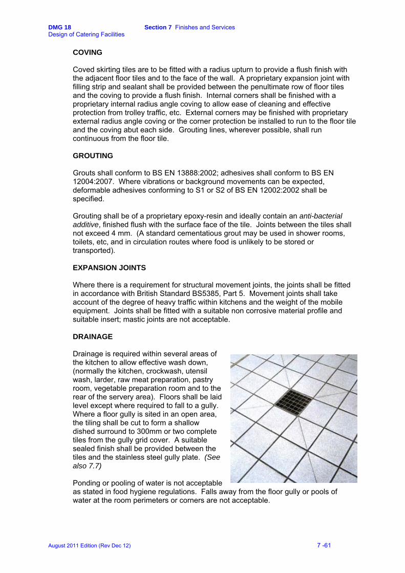
DMG 18 Section 7 Finishes and Services Design of Catering Facilities
COVING
Coved skirting tiles are to be fitted with a radius upturn to provide a flush finish with the adjacent floor tiles and to the face of the wall. A proprietary expansion joint with filling strip and sealant shall be provided between the penultimate row of floor tiles and the coving to provide a flush finish. Internal corners shall be finished with a proprietary internal radius angle coving to allow ease of cleaning and effective protection from trolley traffic, etc. External corners may be finished with proprietary external radius angle coving or the corner protection be installed to run to the floor tile and the coving abut each side. Grouting lines, wherever possible, shall run continuous from the floor tile.
GROUTING Grouts shall conform to BS EN 13888:2002; adhesives shall conform to BS EN 12004:2007. Where vibrations or background movements can be expected, deformable adhesives conforming to S1 or S2 of BS EN 12002:2002 shall be specified. Grouting shall be of a proprietary epoxy-resin and ideally contain an anti-bacterial additive, finished flush with the surface face of the tile. Joints between the tiles shall not exceed 4 mm. (A standard cementatious grout may be used in shower rooms, toilets, etc, and in circulation routes where food is unlikely to be stored or transported). EXPANSION JOINTS Where there is a requirement for structural movement joints, the joints shall be fitted in accordance with British Standard BS5385, Part 5. Movement joints shall take account of the degree of heavy traffic within kitchens and the weight of the mobile equipment. Joints shall be fitted with a suitable non corrosive material profile and suitable insert; mastic joints are not acceptable. DRAINAGE Drainage is required within several areas of the kitchen to allow effective wash down, (normally the kitchen, crockwash, utensil wash, larder, raw meat preparation, pastry room, vegetable preparation room and to the rear of the servery area). Floors shall be laid level except where required to fall to a gully. Where a floor gully is sited in an open area, the tiling shall be cut to form a shallow dished surround to 300mm or two complete tiles from the gully grid cover. A suitable sealed finish shall be provided between the tiles and the stainless steel gully plate. (See also 7.7) Ponding or pooling of water is not acceptable as stated in food hygiene regulations. Falls away from the floor gully or pools of water at the room perimeters or corners are not acceptable.
August 2011 Edition (Rev Dec 12) 7 -61

DMG 18 Section 7 Finishes and Services Design of Catering Facilities
RESILIENT FLOOR COVERINGS Applicable Areas Food preparation and servery areas, utensil wash and crockwash areas, service and delivery lobbies, storerooms, pantry, circulation routes, including entrance lobbies, offices, staff changing areas and rest rooms, dining rooms, and toilets. Bar cellars (resin systems only). Resilient floor coverings including vinyl sheet or resin based systems may be considered within specific or temporary kitchen facilities. Installations shall meet a PTV of 36 (wet)2. A minimum surface roughness of 20μm indicates low risk in wet conditions. The KDEA shall be consulted. Vinyl Floor Coverings
Planning Principles Materials shall be of non-flammable PVC sheet with a plain surface. Sheets in heavy duty areas, where it is considered that there is a significant risk of slipping, shall be specified as a minimum of 3 mm thickness. Other areas such as staff facilities and public areas may be specified as 2-2.5 mm thickness according to the particular density of usage. The floor covering shall be easily cleaned and all joints hot welded to form an impenetrable seal. Sheeting shall be bonded to a suitably prepared substrate as recommended by the manufacturer. The junction between the floor and the wall shall be radiused by a solid ‘cove former’ to provide a flush and sealed finish with the wall to provide an effective bond, smooth finish, and to avoid dirt traps or harbourage for pests. Internal and external corners shall also be radiused and any subsequent joint hot welded to provide an effective seal. Junctions with floor fittings, e.g. floor gullies shall be bonded to form an effective waterproof seal between the sheeting and the stainless steel gully plate. A shallow dished surround to 300 mm of the gully grid cover shall be formed to provide a suitable catchment area to provide effective drainage. (See also 7.7)
Resin System Floors Planning Principles Resin based floors may be installed in differing formulations and finishes to meet the particular specifications of the project. In kitchen and ancillary areas they shall be rated under the Federation of Resin Formulators and Applicators (FeRFA) as Type 8, being 6 mm to 9 mm thick according to the particular density of usage, and be slip, chemical and impact resistant. The product and installation shall meet the requirements of the European Directive on the Hygiene of Foodstuffs (93/43/EEC). In all other areas the installation shall be rated as
2 Source: - Defence Estates Property Directorate Safety Alert. (SA 07/09)
August 2011 Edition (Rev Dec 12) 7 -62
DMG 18 Section 7 Finishes and Services Design of Catering Facilities
Type 5, being 2 mm to 3 mm thick and be slip, chemical and impact resistant.
SOFT FLOOR COVERINGS Applicable Areas Dining rooms and Staff Rest Rooms. Planning Principles Soft floor finishes shall be used in dining rooms of establishments that need to host formal occasions and/or where daily usage is of a sedentary nature. They shall not be fitted in establishments where the daily usage will incur heavy soiling. The provision of a soft finish shall be agreed with the Project Sponsor and the relevant KDEA. Soft floor finishes shall be hardwearing and easily cleaned. Carpet tiles may be considered to provide flexibility and ease of replacement. The soft floor covering shall be laid on a smooth screed surface, pre-treated with a sealing agent and on a suitable underlay as approved and recommended by the manufacturer. Where it is proposed to use alternative floor finishes to those listed above, the relevant KDEA shall be consulted.
August 2011 Edition (Rev Dec 12) 7 -63

DMG 18 Section 7 Finishes and Services Design of Catering Facilities
7.3 WALLS
CONSTRUCTION Internal walls throughout the catering facility shall be of solid construction. Where cavities or service ducts are unavoidable they shall be filled and sealed to prevent the harbourage of insects and pests. Finishes to walls shall be impervious, washable, of non-toxic materials, provide a smooth surface to a height appropriate for the operation and must be easy to maintain, clean and disinfect. Colour finishes shall be of light or pastel colours, with an eggshell/satin finish to avoid glare. DWARF WALLS Many messes are planned with a central kitchen surrounded by the ancillary working areas and stores. To allow maximum benefit of available natural light and to provide a conducive working environment, it is recommended that, where appropriate, dwarf walls be used to separate the working areas, e.g. pastry room or utensil wash from the kitchen. Dwarf walls shall be approximately 1200/1800mm high, with a sloping or ridged 16swg, 304-grade stainless steel top, angled at 20°. Dwarf walls in cool zone rooms such as the Larder and Raw Meat Preparation rooms shall be a minimum of 1800mm high to avoid any risk of contamination from splashing .
PROTECTION OF WALLS
Damage occurs from the use of mobile equipment. To provide additional protection and reduce through-life maintenance costs, all exposed vertical corners shall be fitted with stainless steel or a proprietary high-impact resistant PVC protection to the full height of the room. The fitting may sit on the floor tile to form a more robust corner installation. Corner guards are to be fitted prior to tiling with a secure fixing to the wall structure, the tiling is to abut the protective angle to provide a flush finish. This application will also apply to customer service areas where the pedestrian traffic is considered to be heavy.
August 2011 Edition (Rev Dec 12) 7 -64

DMG 18 Section 7 Finishes and Services Design of Catering Facilities
Horizontal protection of proprietary high-impact resistant PVC shall be provided on main trolley routes and free standing areas to the rear of all mobile equipment. The system used shall be close fitting to the wall and fixed at a height of approximately 700mm, extending up to 900mm AFFL. In particularly heavy traffic areas such as delivery bays and low-level storage areas such as dunnage racking in the Vegetable Preparation room, or where low-height equipment is in use, consideration shall be given to additional horizontal protection at a lower level of approximately 300mm, extending up to 500mm AFFL. The fittings to be sealed at the top and lower edges with the ends stopped to prevent harbourage of pests.
DINING ROOMS Dining rooms and customer areas shall provide modern and pleasant surroundings with due consideration being given to the CRL strategy in junior ranks’ dining rooms. The selected finishes shall be durable, impervious and easy to clean. Wall protection is required in the entrance, queue space and servery areas.
CELLARS – BEER STORE Walls shall be finished with an epoxy resin coating applied direct to a plastered wall. This may also be applied directly to a sealed breeze block finish, however, this shall only be considered where the finish of the block is smooth. Stainless steel sheeting may be provided to the lower levels to provide a finish and additional protection from damage. Vertical and horizontal wall protection shall be fitted according to the particular specification to prevent damage from the movement of barrels etc. (See also Section 9 - Bar and Cellars)
CERAMIC TILES Applicable areas
• All food preparation and cooking areas. • Utensil and Crockwash areas. • Servery area and Pantry. • Food storage areas. • Circulation routes including kitchen entrance areas. • Staff and customer showers and toilets.
Planning Principles Ceramic tiles shall comply with the relevant standards defined at BS6431 and shall be laid in accordance with British Standard BS5385 and The Tile Association (TTA) Technical Advice Note 7 (The design and installation of ceramic wall and floor tiling in
August 2011 Edition (Rev Dec 12) 7 -65
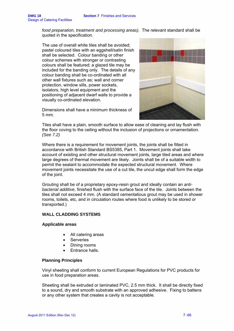
DMG 18 Section 7 Finishes and Services Design of Catering Facilities
food preparation, treatment and processing areas). The relevant standard shall be quoted in the specification. The use of overall white tiles shall be avoided; pastel coloured tiles with an eggshell/satin finish shall be selected. Colour banding or other colour schemes with stronger or contrasting colours shall be featured; a glazed tile may be included for the banding only. The details of any colour banding shall be co-ordinated with all other wall fixtures such as; wall and corner protection, window sills, power sockets, isolators, high level equipment and the positioning of adjacent dwarf walls to provide a visually co-ordinated elevation. Dimensions shall have a minimum thickness of 5 mm. Tiles shall have a plain, smooth surface to allow ease of cleaning and lay flush with the floor coving to the ceiling without the inclusion of projections or ornamentation. (See 7.2) Where there is a requirement for movement joints, the joints shall be fitted in accordance with British Standard BS5385, Part 1. Movement joints shall take account of existing and other structural movement joints, large tiled areas and where large degrees of thermal movement are likely. Joints shall be of a suitable width to permit the sealant to accommodate the expected structural movement. Where movement joints necessitate the use of a cut tile, the uncut edge shall form the edge of the joint. Grouting shall be of a proprietary epoxy-resin grout and ideally contain an anti-bacterial additive, finished flush with the surface face of the tile. Joints between the tiles shall not exceed 4 mm. (A standard cementatious grout may be used in shower rooms, toilets, etc, and in circulation routes where food is unlikely to be stored or transported.) WALL CLADDING SYSTEMS Applicable areas
• All catering areas • Serveries • Dining rooms • Entrance halls.
Planning Principles Vinyl sheeting shall conform to current European Regulations for PVC products for use in food preparation areas. Sheeting shall be extruded or laminated PVC, 2.5 mm thick. It shall be directly fixed to a sound, dry and smooth substrate with an approved adhesive. Fixing to battens or any other system that creates a cavity is not acceptable.
August 2011 Edition (Rev Dec 12) 7 -66
DMG 18 Section 7 Finishes and Services Design of Catering Facilities
PVC sheeting can be adversely affected if its surface temperature exceeds 60°C. Where it is anticipated that the temperature will be in excess of this, then a thermoplastic PVC sheet with a glass fibre core or stainless steel sheet shall be installed. All PVC cladding shall have a minimum Fire Rating: Class1 and Class 0, BS 476; Parts 6 and 7. Joints between sheets shall be connected either by welded joints or by extended joining strips. All corners shall be thermo-formed and all perimeter edges are to be effectively sealed with a food-safe silicon sealant. The use of overall white surfaces shall be avoided; pastel colours with an eggshell/satin finish shall be selected. Colour banding or other colour schemes with stronger or contrasting colours may be featured.
PAINT ON HARD PLASTER Applicable areas:
Staff accommodation Customer and storage areas including beer cellars.
Planning Principles In heavily used areas painted walls shall be of an oil-based eggshell finish, impervious, smooth and easily cleaned. In lighter use areas, an emulsion satin finish may be used. Epoxy wall finishes may also be considered for short-term use (up to five years) for the refurbishment of existing kitchen facilities.
7.4 CEILINGS
Ceilings and overhead fixtures shall be designed, constructed and finished to prevent the accumulation of dirt, reduce condensation and the growth of undesirable moulds and the shedding of particles. Integrated ceilings shall be provided which contain integral vapour-proof lighting and ventilation systems in a sealed unit. Materials used must be non-combustible and provide a smooth, impervious hygienic surface that is easily cleaned and maintained. The ceiling void shall be of a sufficient size to accommodate ventilation ductwork and mains services and be provided with adequate access for cleaning, maintenance and pest control purposes. All ducts, pipe work and conduits, etc, shall be correctly caulked and sealed. Ceiling heights shall be set between 2.5 and 3.0 m AFFL according to the particular performance requirements. All aspects regarding the installation of ceilings and associated ventilation systems shall be referred to the Defence Fire Adviser.
August 2011 Edition (Rev Dec 12) 7 -67

DMG 18 Section 7 Finishes and Services Design of Catering Facilities
VENTILATED CEILINGS Applicable Areas
• Kitchen • Pastry preparation • Crockwash and utensil wash.
Planning Principles See Section 7.11 - Ventilation.
SUSPENDED CEILINGS Applicable Areas
• All catering areas • Serveries • Beer cellars • Entrance halls.
Planning Principles Where it is not practical to provide a ventilated ceiling, a suspended ceiling shall be used in conjunction with traditional extract canopies and an integral ventilation system. Ceiling tiles shall be impervious with a plain smooth surface for ease of cleaning. Metal tiles having a white powder coating or PVC finish are the preferred option. Polystyrene and fibre tiles are not acceptable. Tiles shall be appropriately secured to the frame to prevent lifting and provide for ease of access for cleaning, maintenance and pest control. In temperature-controlled rooms insulation contained in vapour proof bags shall be provided to the back of the tiles to prevent condensation; loose insulation is not acceptable. Particular attention shall be made to the thermal transmittance properties of the ceiling tiles ('U value') in the larder and raw meat preparation areas to ensure that there is no condensation and that a constant temperature of +13°C can be maintained.
7.5 DOORS
Applicable Areas
• All catering areas • Serveries • Dining rooms • Staff facilities • Beer cellars.
August 2011 Edition (Rev Dec 12) 7 -68
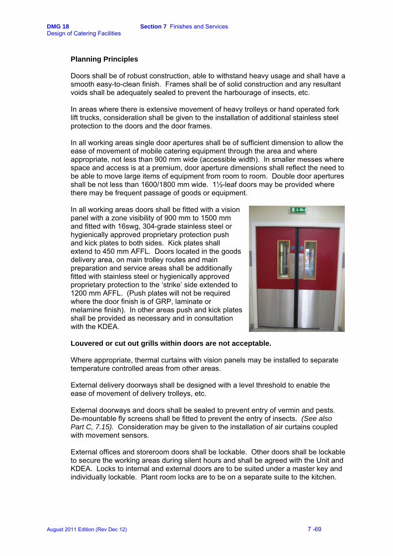
DMG 18 Section 7 Finishes and Services Design of Catering Facilities
Planning Principles Doors shall be of robust construction, able to withstand heavy usage and shall have a smooth easy-to-clean finish. Frames shall be of solid construction and any resultant voids shall be adequately sealed to prevent the harbourage of insects, etc. In areas where there is extensive movement of heavy trolleys or hand operated fork lift trucks, consideration shall be given to the installation of additional stainless steel protection to the doors and the door frames. In all working areas single door apertures shall be of sufficient dimension to allow the ease of movement of mobile catering equipment through the area and where appropriate, not less than 900 mm wide (accessible width). In smaller messes where space and access is at a premium, door aperture dimensions shall reflect the need to be able to move large items of equipment from room to room. Double door apertures shall be not less than 1600/1800 mm wide. 1½-leaf doors may be provided where there may be frequent passage of goods or equipment. In all working areas doors shall be fitted with a vision panel with a zone visibility of 900 mm to 1500 mm and fitted with 16swg, 304-grade stainless steel or hygienically approved proprietary protection push and kick plates to both sides. Kick plates shall extend to 450 mm AFFL. Doors located in the goods delivery area, on main trolley routes and main preparation and service areas shall be additionally fitted with stainless steel or hygienically approved proprietary protection to the ‘strike’ side extended to 1200 mm AFFL. (Push plates will not be required where the door finish is of GRP, laminate or melamine finish). In other areas push and kick plates shall be provided as necessary and in consultation with the KDEA. Louvered or cut out grills within doors are not acceptable. Where appropriate, thermal curtains with vision panels may be installed to separate temperature controlled areas from other areas. External delivery doorways shall be designed with a level threshold to enable the ease of movement of delivery trolleys, etc. External doorways and doors shall be sealed to prevent entry of vermin and pests. De-mountable fly screens shall be fitted to prevent the entry of insects. (See also Part C, 7.15). Consideration may be given to the installation of air curtains coupled with movement sensors. External offices and storeroom doors shall be lockable. Other doors shall be lockable to secure the working areas during silent hours and shall be agreed with the Unit and KDEA. Locks to internal and external doors are to be suited under a master key and individually lockable. Plant room locks are to be on a separate suite to the kitchen.
August 2011 Edition (Rev Dec 12) 7 -69

DMG 18 Section 7 Finishes and Services Design of Catering Facilities
Ironmongery shall be of heavy-duty stainless steel for external and catering areas use. All doors are to be fitted with the appropriate signage, the finish to be food safe and easily cleaned. Doorstops are to be fitted, where appropriate, to prevent damage to the infrastructure and positioned so as not to present a trip hazard when the door is closed. The Defence Fire Adviser shall be consulted on the means of escape, including the location and requirements for fire doors.
7.6 WINDOWS
Applicable Areas
• All catering areas • Serveries • Staff rest facilities.
Planning Principles
In all catering areas including the utensil and crockwash, serveries and pantries, windows shall be sealed and do not, therefore, require a fly screen to be fitted. Where opening windows are provided, fly screens shall be fitted as required by the EHO. Fly screens shall be of robust construction and capable of being easily removed and fitted for cleaning and maintenance purposes.
Internal sills shall slope from the window frame at an angle of approximately 20° for ease of cleaning and to prevent items being placed upon them.
Wherever possible, to enable the best use of
natural light, high-level windows shall be provided in stores areas and refrigeration rooms to make the best use of wall space for racking and refrigeration cabinets. For safety reasons, glazing shall not be fitted below 800 mm AFFL. Standard roof lights shall not be provided within catering areas. Where refurbishment is being undertaken, existing roof lights may be removed or permanently sealed. Where natural daylight is required to be introduced into corridor areas, etc, then sealed reflective light systems may be installed. Certain locations may be sensitive security areas and windows may require additional protection. The KDEA shall be consulted.
August 2011 Edition (Rev Dec 12) 7 -70

DMG 18 Section 7 Finishes and Services Design of Catering Facilities
Part B – Services and Services Co-ordination 7.7 DRAINAGE AND WASTE DISPOSAL
Drainage facilities shall be adequate for the purpose intended and designed and constructed to avoid the contamination of foodstuffs. They shall have sufficient fall to allow all solid and liquid waste to flow away with the minimum number of bends. The direction of flow shall be away from 'clean' areas to 'dirty' areas and toilets shall feed into the system after the kitchen. All appliances and floor gullies connected to the drainage system shall be provided with an effective trap. Manholes and inspection chambers must not be installed in food rooms. Rodding points shall, where possible, be located in a position outside the catering area and effectively sealed. Grease traps shall not be installed within the catering premises. (See Waste Disposal) FLOOR DRAINAGE
Applicable Areas
• Kitchen, including in front of bratt pan and water boiler • Utensil wash • Crockwash • Larder • Raw meat preparation • Vegetable preparation • Pastry preparation • Refuse areas • Beer cellars.
Provision of gullies in other areas shall be agreed with the KDEA
Planning Principles
Floor drainage is required for cleaning purposes and to receive discharge from cooking appliances. Gullies, tray gullies and gratings shall conform to BS EN 1433 (Gullies for Buildings), the load class selected appropriate to the application. They shall be manufactured from an austenitic 304-grade, 14swg (2 mm) minimum, stainless steel, fitted with removable foul air trap and stainless steel strainer/silt basket. An anti-slip grade-304 stainless steel grating shall be fitted, its perimeters reinforced with stainless steel angular frame suitably sealed with the surrounding floor finish to provide an
August 2011 Edition (Rev Dec 12) 7 -71
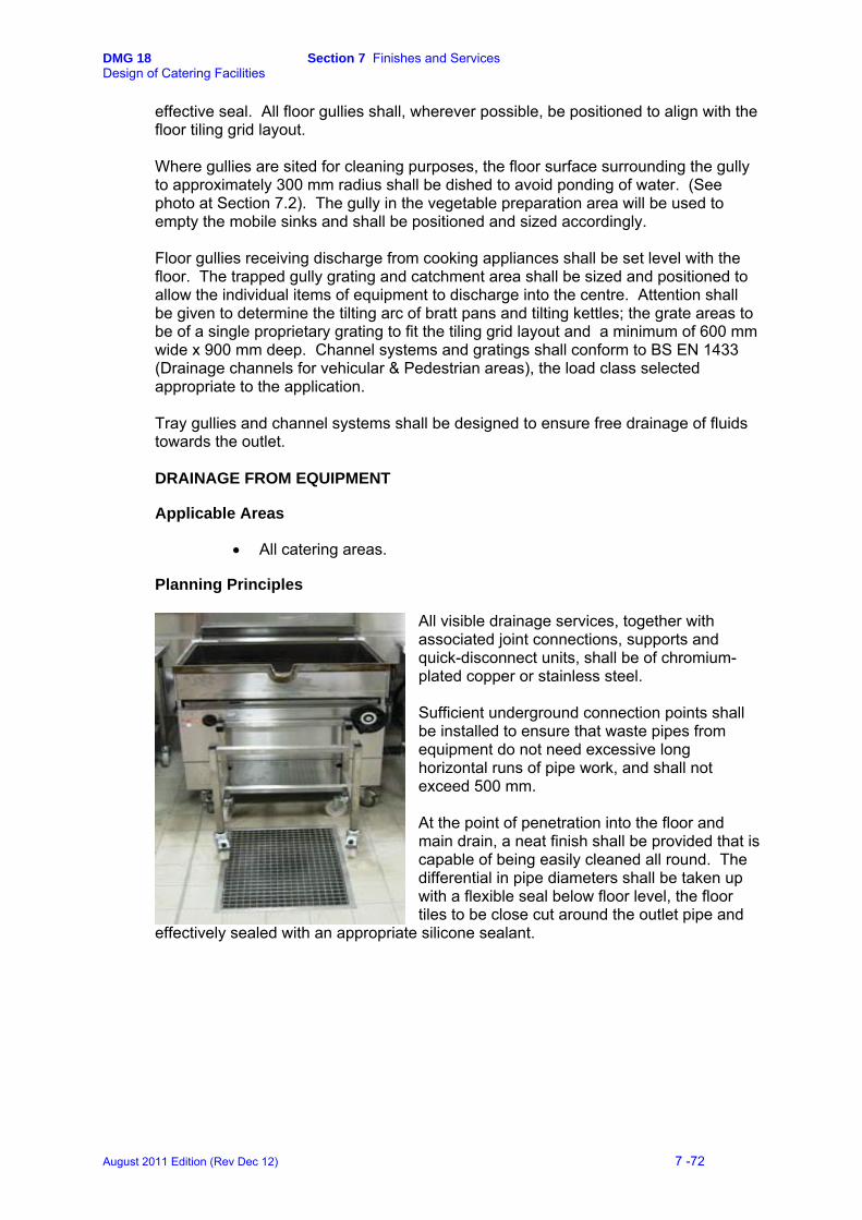
DMG 18 Section 7 Finishes and Services Design of Catering Facilities
effective seal. All floor gullies shall, wherever possible, be positioned to align with the floor tiling grid layout. Where gullies are sited for cleaning purposes, the floor surface surrounding the gully to approximately 300 mm radius shall be dished to avoid ponding of water. (See photo at Section 7.2). The gully in the vegetable preparation area will be used to empty the mobile sinks and shall be positioned and sized accordingly. Floor gullies receiving discharge from cooking appliances shall be set level with the floor. The trapped gully grating and catchment area shall be sized and positioned to allow the individual items of equipment to discharge into the centre. Attention shall be given to determine the tilting arc of bratt pans and tilting kettles; the grate areas to be of a single proprietary grating to fit the tiling grid layout and a minimum of 600 mm wide x 900 mm deep. Channel systems and gratings shall conform to BS EN 1433 (Drainage channels for vehicular & Pedestrian areas), the load class selected appropriate to the application. Tray gullies and channel systems shall be designed to ensure free drainage of fluids towards the outlet.
DRAINAGE FROM EQUIPMENT Applicable Areas
• All catering areas. Planning Principles
All visible drainage services, together with associated joint connections, supports and quick-disconnect units, shall be of chromium-plated copper or stainless steel.
Sufficient underground connection points shall be installed to ensure that waste pipes from equipment do not need excessive long horizontal runs of pipe work, and shall not exceed 500 mm.
At the point of penetration into the floor and main drain, a neat finish shall be provided that is capable of being easily cleaned all round. The differential in pipe diameters shall be taken up with a flexible seal below floor level, the floor tiles to be close cut around the outlet pipe and
effectively sealed with an appropriate silicone sealant.
August 2011 Edition (Rev Dec 12) 7 -72

DMG 18 Section 7 Finishes and Services Design of Catering Facilities
Each waste outlet shall have a trapped connection close to the equipment prior to connection to the drainage system. Cleaning eyes shall be provided to traps below each item of equipment, the waste outlet being easily de-mountable for clearance of blockages.
Potato peelers and vegetable preparation equipment shall discharge via an approved waste dilution unit and trap to the drainage system. The branch waste pipe shall be as short as possible and connection to the head of the system shall be avoided. Where walk-in refrigeration and air-cooling plant is installed, drainage will need to be provided to accept the defrost condensate. FOOD WASTE DISPOSAL Applicable Areas
• Kitchens • Utensil wash • Crockwash • Vegetable preparation • Refuse area.
Planning Principles: The disposal of waste food shall take due consideration of the Environmental Protection Act 1990, the Animal By-products (Enforcement) (England) Regulations 2011, and subsequent Waste Control Regulations and Landfill Directives. Every effort shall be made to ensure that the drainage system is kept free from Fats, Oils and Grease (FOG). The Local Authority (LA) policy regarding the disposal of waste food products shall be sought prior to designing the waste disposal system. Similarly, where units have their own sewage treatment works, consultation shall be made with the Property Manager or Project Aquatrine.
Potato peelers and vegetable processors shall discharge into the drainage system via an approved waste dilution unit and avoid passing through any external grease traps. Where it is anticipated that the levels of FOG will be high, consideration may be given to the installation of an approved automatic FOG recovery and removal unit. Consult the relevant KDEA. Alternative systems of food waste disposal may be considered within the unit Environmental Health Policy that avoid sending food waste into the LA sewage system or to landfill. Such systems may include ‘accelerated decomposition’,
August 2011 Edition (Rev Dec 12) 7 -73
DMG 18 Section 7 Finishes and Services Design of Catering Facilities
composting, or a waste vacuum dedicated storage system for off site processing. Consult the relevant KDEA. (See also Part E - 7.17 Food Waste Management) BIO-REMEDIATION FOG shall be treated by an approved bio-remediation system designed to incorporate automatic dosing of the biological product into the head(s) of the drainage system. As a minimum, the areas that require treatment are, the drain runs from the crockwash, utensil wash and kitchen cooking suite where combination ovens are sited. The dosing equipment shall be located in the plant room or in a location accessed directly from outside, not via the catering areas. The system shall be dispensed by a timed system allowing overnight injection into the drainage system to allow maximum treatment time. Replenishment and maintenance of the product and auto-dosing equipment shall be the responsibility of the Facilities Manager. Chemical based products shall not be used to treat FOG. Grease traps may be installed on the external drainage system in addition to the bio-remediation system. The installation of under-bench recovery, separation or grease traps within the building are not acceptable.
August 2011 Edition (Rev Dec 12) 7 -74

DMG 18 Section 7 Finishes and Services Design of Catering Facilities
7.8 WATER SUPPLY
INTRODUCTION Applicable Areas
• All catering areas • Staff facilities • Customer toilets.
Planning Principles An adequate supply of clean hot and /or cold potable water is required and must meet the statutory requirements of the water supply authority. All visible supply services together with associated joint connections, supports and quick-disconnect units, shall be of chromium-plated copper or stainless steel.
Supply services to equipment shall avoid the installation of excessively long horizontal runs and shall not exceed 500 mm. Services shall be brought to the nearest point to the relevant equipment via a ceiling or service duct and Dropped to Lower Level (DTLL) adjacent to the connection point to the equipment. Pipes shall not be fixed closer than 35 mm to the wall, and be not lower than 450 mm AFFL. All pipework shall be adequately secured by smooth finish stainless steel pipe brackets. Multiple services DTLL shall be set at a minimum of 50 mm apart.
Pipe penetrations into walls and ceilings shall be fully caulked with mastic or grout as appropriate and fitted with cloaking rings or roses. (The fitting of cloaking rings and roses over unsealed penetrations is not acceptable)
Prime cooking equipment requiring water connections shall be fitted with flexible final services connections and quick disconnect valves. These and associated brake/safety devices shall comply with the relevant Regulations.
Preparation sinks shall be fitted with 22 mm taps, having a flow rate of not less than 0.35 lts/sec. (5gals/min) Water hoses shall be permanently coiled and retractable to the appropriate bore and length of the host unit. They shall be constructed from spiral polyurethane with brass
August 2011 Edition (Rev Dec 12) 7 -75

DMG 18 Section 7 Finishes and Services Design of Catering Facilities
end fittings. They shall be fitted with a brass two-way quick-disconnect fitting and smooth outer sleeve suitable for catering installations. WATER QUALITY & TREATMENT Potable cold water shall be supplied directly from the mains supply pipe to all food preparation sinks, drinking water points, cooking equipment, beverage making equipment and ice making machines. All sinks and wash hand basins require a hot and cold water supply with the exception of the potato preparation sink. An external cold water supply suitably protected from frost conditions shall be supplied to the refuse area. ‘Grey water’ may be considered for the flushing of toilets. Many items of equipment have exacting requirements for the constant quality of water supply to enable them to function efficiently. These include minimum/maximum pressure ranges, the degree of mineral content that could cause scale formation and the pH level. The layout and design for the provision of the water supply shall take account of the individual equipment requirements in order that manufactures’ warranties are not invalidated, however, this shall not affect the requirement to provide potable cold water supplied directly from the mains supply pipe to all food preparation sinks, drinking water points, cooking equipment, beverage making equipment and ice making machines. Equipment manufacturers and the KDEA shall be consulted. (See also- Water Storage.) In all circumstances, the water hardness shall be measured on the Clark scale. Water hardness above 6° Clark scale shall be softened at source through a salt base exchange unit for treatment of the water supply to:
• Sanitation sinks • Dishwashers • Utensil washers • Glass washers • Bains-marie •
Individual stand-alone softening units or filter systems adjacent to the equipment may only be considered in exceptional circumstances. Consult the relevant KDEA. Treated, conditioned drinking water, by a food-safe method such as in line electronic or digital systems, in-line filter cylinders or replacement filter cartridge systems shall be supplied to:
• Combination ovens • Pressure/pressureless steaming
ovens • Beverage making equipment
August 2011 Edition (Rev Dec 12) 7 -76
DMG 18 Section 7 Finishes and Services Design of Catering Facilities
• Water boilers
Where the conditioning apparatus is sited adjacent to the equipment, suitable storage racking or space within a service spine shall be provided to ensure that the surrounding area is capable of being easily cleaned. Where the cold water supply is not potable throughout the unit, drinking water points shall be suitably labelled. WATER STORAGE AND METERING The storage of hot and cold water shall comply with current regulations including the relevant water authority regulations – HSC ACoP L8, Statutory Instrument 1999 No.1148 The Water Supply (Water Fittings) Regulations 1999 and BS 6700: 1997 -Design, installation, testing and maintenance of services supplying water for domestic use within buildings and their curtilages. Hot and cold water consumption and storage capacities shall be based on the recommendations in the relevant CIBSE and Defence Estates/Defence Infrastructure Organisation guides and in particular shall take account of the following:
• NTBF • That each unit serves a minimum of three meals per day • PAYD/CRL operating times • The unit's individual demand pattern • Any special unit requirements including out of hours functions • Specific items of catering equipment that require large volumes of treated
water • Male and female staff facilities inclusive of showers.
Water storage for the catering facility may be separate from any other storage that may be required for living or other accommodation within the building. Where the storage facility is combined, adequate provision shall be made to take account of equalised peak usage times, e.g. early morning wake up - v - breakfast service. Account shall be taken of the capacity of the water treatment plant and the availability of treated/conditioned water to the catering equipment, to be able to supply sufficient water to all items of equipment throughout the working day. Water consumption in the catering facility shall be separately metered from any other consumption within the building. Consumption shall be measured via a digitally pulsed meter, complete with an interface unit and 30-minute recording facility, linked to the Building Energy Management System (BEMS). Where considered to be viable, the system shall be linked to a PC and software package located in the Kitchen Office and capable of inter-facing with the BEMS.
August 2011 Edition (Rev Dec 12) 7 -77

DMG 18 Section 7 Finishes and Services Design of Catering Facilities
7.9 GAS
INTRODUCTION Natural gas is the preferred fuel for prime cooking equipment. Installations shall meet the requirements of the Gas Safety Regulations Apr 2009, the Health & Safety Commission Approved Code of Practice (ACOP) "Safety in the installation and use of gas systems and appliances.” 1994, BS 6173:2001. Applicable Areas
• Kitchens.
Planning Principles
All gas installations shall comply with current Gas Safety Regulations, the relevant British Standards Codes of Practice, Defence Estates/Defence Infrastructure Organisation Specification and Functional Standards publications, CIBSE publications and any relevant European Normalisations.
An interlock of the gas supply and the mechanical ventilation system that will shut off the gas supply in the event of an air movement failure shall be provided and meet the Emergency Isolation Requirements of BS 6173 (including Gas and Electric isolation and the interlocking of gas supply with any mechanical supply or extract ventilation system). (See also-Ventilation 7.11) Gas supply pipes shall be kept as short as possible and concealed within a service spine or ceiling void. Where exposed, they shall be painted with acrylic non-chip ochre yellow paint. Prime cooking equipment requiring gas connections shall be fitted with flexible final services connections and quick disconnect valves. These and associated brake/safety devices shall comply with the relevant Regulations. The gas hose shall be constructed from 304-grade stainless steel helical wound, annealed with an external stainless steel wire braid connection, and finished with a permanently bonded PVC heat resistant dipped coating. The quick disconnect valve shall be brass, ‘push to connect’ operation with a flat face finish and a Thermal Shut off/fusible link complete with a ¼-turn isolation valve. Both ends of the hose shall be fitted with a Supr-swivel multi-plane elbow, fitted so as to provide 360° in one plane and 270° rotation in the opposing plane. (See also-Services Co-ordination – 7.13). Isolators shall be easily accessible, sited in a safe location to the user and clearly labelled.
METERS Gas consumption in the catering facility shall be separately metered from any other consumption within the building. An automatic gas meter shall be installed specifically for the catering area consumption via a digitally pulsed meter complete with an interface unit and 30-minute recording facility linked to the BEMS. Where considered to be viable, the system shall be linked to a PC and software package located in the Kitchen Office and capable of inter-facing with the BEMS.
August 2011 Edition (Rev Dec 12) 7 -78

DMG 18 Section 7 Finishes and Services Design of Catering Facilities
EMERGENCY ISOLATION
Emergency isolators (panic buttons) shall be installed adjacent to the main entrances/exits and emergency exits. They shall be manually operable, suitably protected against accidental use and clearly labelled. The design shall be such that a single emergency isolator shall cut off both the gas and electrical supplies and that authorised staff such as the Works Services Manager (WSM) only can carry out the re-connection of the supply.
The Defence Fire Adviser shall be consulted on all matters regarding the installation, position and isolation of gas supplies.
August 2011 Edition (Rev Dec 12) 7 -79
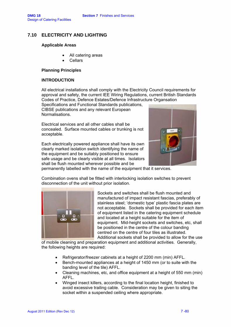
DMG 18 Section 7 Finishes and Services Design of Catering Facilities
7.10 ELECTRICITY AND LIGHTING
Applicable Areas
• All catering areas • Cellars
Planning Principles
INTRODUCTION All electrical installations shall comply with the Electricity Council requirements for approval and safety, the current IEE Wiring Regulations, current British Standards Codes of Practice, Defence Estates/Defence Infrastructure Organsation Specifications and Functional Standards publications, CIBSE publications and any relevant European Normalisations. Electrical services and all other cables shall be concealed. Surface mounted cables or trunking is not acceptable. Each electrically powered appliance shall have its own clearly marked isolation switch identifying the name of the equipment and be suitably positioned to ensure safe usage and be clearly visible at all times. Isolators shall be flush mounted wherever possible and be permanently labelled with the name of the equipment that it services. Combination ovens shall be fitted with interlocking isolation switches to prevent disconnection of the unit without prior isolation.
Sockets and switches shall be flush mounted and manufactured of impact resistant fascias, preferably of stainless steel; ‘domestic type’ plastic fascia plates are not acceptable. Sockets shall be provided for each item of equipment listed in the catering equipment schedule and located at a height suitable for the item of equipment. Mid-height sockets and switches, etc, shall be positioned in the centre of the colour banding centred on the centre of four tiles as illustrated. Additional sockets shall be provided to allow for the use
of mobile cleaning and preparation equipment and additional activities. Generally, the following heights are required:
• Refrigerator/freezer cabinets at a height of 2200 mm (min) AFFL. • Bench-mounted appliances at a height of 1450 mm (or to suite with the
banding level of the tile) AFFL. • Cleaning machines, etc, and office equipment at a height of 550 mm (min)
AFFL. • Winged insect killers, according to the final location height, finished to
avoid excessive trailing cable. Consideration may be given to siting the socket within a suspended ceiling where appropriate.
August 2011 Edition (Rev Dec 12) 7 -80
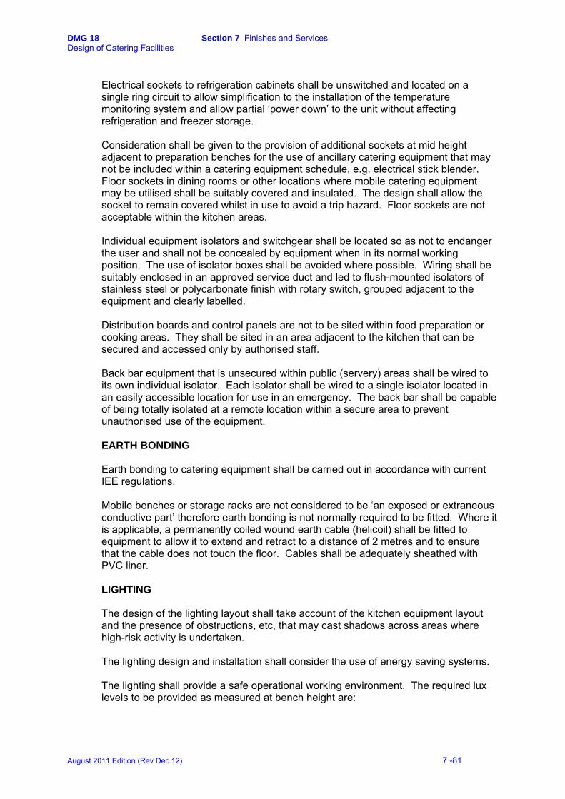
DMG 18 Section 7 Finishes and Services Design of Catering Facilities
Electrical sockets to refrigeration cabinets shall be unswitched and located on a single ring circuit to allow simplification to the installation of the temperature monitoring system and allow partial ‘power down’ to the unit without affecting refrigeration and freezer storage. Consideration shall be given to the provision of additional sockets at mid height adjacent to preparation benches for the use of ancillary catering equipment that may not be included within a catering equipment schedule, e.g. electrical stick blender. Floor sockets in dining rooms or other locations where mobile catering equipment may be utilised shall be suitably covered and insulated. The design shall allow the socket to remain covered whilst in use to avoid a trip hazard. Floor sockets are not acceptable within the kitchen areas. Individual equipment isolators and switchgear shall be located so as not to endanger the user and shall not be concealed by equipment when in its normal working position. The use of isolator boxes shall be avoided where possible. Wiring shall be suitably enclosed in an approved service duct and led to flush-mounted isolators of stainless steel or polycarbonate finish with rotary switch, grouped adjacent to the equipment and clearly labelled. Distribution boards and control panels are not to be sited within food preparation or cooking areas. They shall be sited in an area adjacent to the kitchen that can be secured and accessed only by authorised staff. Back bar equipment that is unsecured within public (servery) areas shall be wired to its own individual isolator. Each isolator shall be wired to a single isolator located in an easily accessible location for use in an emergency. The back bar shall be capable of being totally isolated at a remote location within a secure area to prevent unauthorised use of the equipment.
EARTH BONDING Earth bonding to catering equipment shall be carried out in accordance with current IEE regulations. Mobile benches or storage racks are not considered to be ‘an exposed or extraneous conductive part’ therefore earth bonding is not normally required to be fitted. Where it is applicable, a permanently coiled wound earth cable (helicoil) shall be fitted to equipment to allow it to extend and retract to a distance of 2 metres and to ensure that the cable does not touch the floor. Cables shall be adequately sheathed with PVC liner. LIGHTING The design of the lighting layout shall take account of the kitchen equipment layout and the presence of obstructions, etc, that may cast shadows across areas where high-risk activity is undertaken. The lighting design and installation shall consider the use of energy saving systems. The lighting shall provide a safe operational working environment. The required lux levels to be provided as measured at bench height are:
August 2011 Edition (Rev Dec 12) 7 -81

DMG 18 Section 7 Finishes and Services Design of Catering Facilities
• 500-lux in the kitchen, pastry preparation larder preparation, raw meat preparation, vegetable preparation and pantry, refrigeration/deep freeze walk in facilities
• 300-lux in the crockwash, utensil wash, kitchen food store, grocery store, and servery area.
• 125-lux in the equipment store, crockery, glass and linen store, cleaner’s room, wet and dry refuse/compactor areas and insulated container washroom.
• 350-lux in the kitchen office. Light fittings shall be vapour proof in all catering areas and form an integral part of the ceiling system. Surface-mounted systems are not acceptable. Where extraction canopies are installed, vapour proof light fittings shall be fitted within the canopy to ensure that there is adequate lighting for safe working. External weatherproof lighting shall be provided at entrances, loading and refuse areas. Spot lighting and the use of tungsten filament lamps may be considered for use in the dining room and other customer areas to provide a more convivial environment. METERS Electricity consumption in the catering facility shall be separately metered from any other consumption within the building. An automatic electricity meter shall be installed specifically for the catering area. Consumption shall be measured via a digitally pulsed meter complete with an interface unit and 30-minute recording facility linked to the BEMS. Where considered to be viable, the system shall be linked to a PC and software package located in the Kitchen Office and capable of inter-facing with the BEMS. EMERGENCY ISOLATION Emergency isolators (panic buttons) shall be installed adjacent to the main entrances/exits and emergency exits. They shall be manually operable, suitably protected against accidental use and clearly labelled. The design shall be such that a single emergency isolator shall cut off both the electrical and gas supplies and that authorised staff such as the Works Services Manager (WSM) only can carry out the re-connection of the supply. The Defence Fire Adviser shall be consulted on all matters regarding the installation, siting and isolation of services.
August 2011 Edition (Rev Dec 12) 7 -82

DMG 18 Section 7 Finishes and Services Design of Catering Facilities
7.11 VENTILATION
Applicable Areas
• All catering areas • Storerooms • Staff facilities • Dining rooms • Cellars • Toilets areas.
Planning Principles INTRODUCTION Ventilation design is fundamental to the efficient environmental operation of a catering unit and must incorporate a number of features including: the capture of smoke, steam, fumes and odours; grease extraction and disposal; reduction of carbon monoxide levels; fire protection and the maintenance of acceptable air quality and temperature. The design of the ventilation system shall be in accordance with current British Standards Codes of Practice, Defence Estates/Defence Infrastructure Organisation Specifications and Functional Standards publications, CIBSE publications and any relevant European Normalisations. In particular, the design shall meet DW172 Heating & Ventilation Contractors Association (HVCA)– Standards for Kitchen Ventilation Systems, unless specified differently. The design shall comply with The Food Hygiene (England) (No.2) Regulations 2006. (Regulation (EC) No.852/2004 on the hygiene of foodstuffs)3 and the Workplace (Health, Safety & Welfare) Regulations 1992 in that:
• There must be suitable and sufficient means of natural or mechanical ventilation to ensure that heat and/or humidity do not build up to levels that could compromise the safety of food. (See also Section 7.6-Windows)
• Mechanical airflow must not be from a contaminated area to a clean area., i.e. air drawn into 'clean' preparation areas must not be drawn from 'dirty' areas such as waste storage areas or rooms used for dirty processes such as the utensil wash.
• Construction shall be such that filters and other parts requiring cleaning or replacement are easily accessible and wherever possible, located outside the food preparation rooms.
• Effective and suitable provision shall be made to ensure that every enclosed workplace is ventilated by a sufficient quantity of fresh or purified air.
The Defence Fire Adviser shall be consulted on all matters regarding the installation and design of the ventilation system including the installation of fire rated ducting and zone separation.
3 (and equivalent regulations in Scotland, Wales and Northern Ireland)
August 2011 Edition (Rev Dec 12) 7 -83

DMG 18 Section 7 Finishes and Services Design of Catering Facilities
CONTROLS A variable fan speed control, with the appropriate indicator light and speed setting, shall be located in the kitchen office to suit the particular design. Where individual stand-alone systems are installed, such as back bars, then a single local control may be installed with the appropriate on/off control, indicator light and variable control. Where the ventilation system is controlled by the BEMS, an over ride and control facility shall be provided in the kitchen office. DRAUGHTS AND ODOURS The balance of the ventilation system shall be such that there are no draughts within the buildings or 'wind tunnels' between rooms. The location and style of air supply ventilation grids, particularly in servery areas and above hot service counters, shall be planned to avoid the risk of cool air passing over food, which, in turn, may result in food being held below the temperatures required by food hygiene regulations. Where air transfer grills have to be installed, ease of access to the void without the use of special tools shall be provided for maintenance and cleaning. Transfer grills shall not be fitted into doors. Where the catering facility is an integral part of a building, and there is living or working accommodation or it is in close proximity to residential areas, the external outlets from the extraction system shall be located so that cooking smells, noise, etc, shall not cause a nuisance. The system design shall ensure that cooking odours do not drift from the kitchen to the customer areas. Where the external 'drift' of cooking odours is difficult to control and may be a nuisance, consideration may be given to the installation of an appropriate filter system or the use of ultra violet light within the extract system to neutralise any odours. AIR COOLING – PREPARATION & STORAGE ROOMS In addition to the provision of fresh air and extraction, in the larder and raw meat preparation areas the temperature shall be controlled at +13°C during working hours. The bulk grocery store shall be controlled at +12°C to +16°C and the vegetable preparation and storage room to a maximum of +16°C.
The cooling system shall be a ceiling mounted cassette unit of an adequate size to maintain the desroom temperature, be draught free, easy to clean and incorporate a bactericidal filter. Drainage may berequired to receive condensathe equipme
ired
te from
nt.
The thermostatic variable control shall be manually operated, incorporate a timer with override and
August 2011 Edition (Rev Dec 12) 7 -84
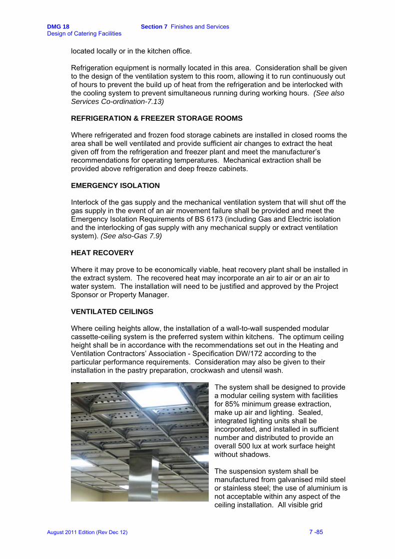
DMG 18 Section 7 Finishes and Services Design of Catering Facilities
located locally or in the kitchen office. Refrigeration equipment is normally located in this area. Consideration shall be given to the design of the ventilation system to this room, allowing it to run continuously out of hours to prevent the build up of heat from the refrigeration and be interlocked with the cooling system to prevent simultaneous running during working hours. (See also Services Co-ordination-7.13) REFRIGERATION & FREEZER STORAGE ROOMS Where refrigerated and frozen food storage cabinets are installed in closed rooms the area shall be well ventilated and provide sufficient air changes to extract the heat given off from the refrigeration and freezer plant and meet the manufacturer’s recommendations for operating temperatures. Mechanical extraction shall be provided above refrigeration and deep freeze cabinets. EMERGENCY ISOLATION Interlock of the gas supply and the mechanical ventilation system that will shut off the gas supply in the event of an air movement failure shall be provided and meet the Emergency Isolation Requirements of BS 6173 (including Gas and Electric isolation and the interlocking of gas supply with any mechanical supply or extract ventilation system). (See also-Gas 7.9) HEAT RECOVERY Where it may prove to be economically viable, heat recovery plant shall be installed in the extract system. The recovered heat may incorporate an air to air or an air to water system. The installation will need to be justified and approved by the Project Sponsor or Property Manager.
VENTILATED CEILINGS Where ceiling heights allow, the installation of a wall-to-wall suspended modular cassette-ceiling system is the preferred system within kitchens. The optimum ceiling height shall be in accordance with the recommendations set out in the Heating and Ventilation Contractors’ Association - Specification DW/172 according to the particular performance requirements. Consideration may also be given to their installation in the pastry preparation, crockwash and utensil wash.
The system shall be designed to provide a modular ceiling system with facilities for 85% minimum grease extraction, make up air and lighting. Sealed, integrated lighting units shall be incorporated, and installed in sufficient number and distributed to provide an overall 500 lux at work surface height without shadows.
The suspension system shall be manufactured from galvanised mild steel or stainless steel; the use of aluminium is not acceptable within any aspect of the ceiling installation. All visible grid
August 2011 Edition (Rev Dec 12) 7 -85

DMG 18 Section 7 Finishes and Services Design of Catering Facilities
components and modules shall be manufactured from 304-grade stainless steel. Vertical plenum partitions or plenum boxes shall be manufactured of suitably protected galvanised steel or stainless steel. Where the system provides for sealed easily cleaned extract and supply plenum areas, the walls and ceiling within the area shall be suitably prepared and sealed with an acrylic type, anti-fungicidal, washable paint to allow ease of maintenance and cleaning and to prevent dust contamination. Where the system provides for extract and supply directly from or into a sealed galvanised mild steel or stainless steel plenum box, the surrounding ceiling void areas shall be suitably treated and sealed for ease of maintenance and cleaning and to prevent dust contamination. The modules shall be easily removable for cleaning without the use of special tools, weigh not more than 4kg to allow ease of handling and be of a size that will pass through a conventional dishwasher (500 mm maximum). The finish may be of stainless steel or colour powder-coated or a combination of both. The overhang of the extraction modules (i.e. the extent in plan beyond the edges of the equipment) shall be set according to the finished height of the ceiling and meet the guidelines set out in HVCA DW/172.
EXTRACTION CANOPIES Where a ventilated ceiling is not viable, a canopy shall be fitted to provide dedicated extraction to prime cooking equipment in the kitchen, the dishwasher in the crockwash, the steriliser sink in the utensil wash and to pressure and large expansion water boilers. Additionally, they shall be sited above any gas equipment, including servery counters where fitted. A box or low-profile canopy is the preferred option above back bar units. Canopies shall be of box construction, manufactured from 304-grade stainless steel, suitably braced and stiffened to prevent distortion, with welded and polished joints. Canopies with sloping sides are not acceptable. An integral, full perimeter condensate channel at the bottom edge shall be included and suitably dimensioned to include a captive finger-tight drain plug to the front edge to provide ease of cleaning and draining. Ductwork to the canopy shall be designed to provide an even extraction of air across the length of the canopy. Where canopies are installed over cooking equipment, grease filters shall be fitted to the full length of the canopy. All components shall be of stainless steel and the baffle filter system installed to include a grease collection drawer suitably located to prevent re-entrainment. (Mesh impingement filters are not acceptable as primary grease filters) All fittings shall be easily removable for cleaning without the use of special tools. Where conditions apply, consideration may be given to incorporating a perimeter air supply within the canopy in conjunction with the overall ventilation system incorporated within the building.
August 2011 Edition (Rev Dec 12) 7 -86
DMG 18 Section 7 Finishes and Services Design of Catering Facilities
Where the production of grease-laden air is excessive, consideration may be given to the installation of a water wash or cold-water mist system. Where the location of the kitchen extract may impact on environmental issues such as residential areas, consideration may be given to the incorporation of an ultra-violet grease and odour destroying cassette within the extraction ductwork. Canopies installed over dishwashers, sterilising sinks and water boilers shall be fitted with an adequate air-handling unit to ensure the efficient removal of water vapour and prevent condensation to the surrounding area. Sealed, integrated lighting units shall be incorporated within the canopy area, to provide an overall 500 lux at work surface height in kitchens and 300 lux in the crockwash and utensil wash. The bottom edge of the canopy shall be installed at a minimum of 2 metres AFFL. The overhang of the canopy (i.e. the extent in plan beyond the edges of the equipment) shall be not less than 450 mm above all general prime cooking equipment and 600 mm above combination ovens, 300 mm above dishwashers, sterilising sinks and glass washers and 150 mm above beverage suites, expansion and pressure water boilers. The back bar cooking equipment must be served by a suitable ventilation system that meets the requirements of Crown Fire Standards, Para. 4.10 of Standard E5. (See also Section 3.2).
August 2011 Edition (Rev Dec 12) 7 -87

DMG 18 Section 7 Finishes and Services Design of Catering Facilities
7.12 HEATING
Applicable Areas
• All catering areas • Storerooms • Offices • Staff facilities • Toilet areas.
Planning Principles Heating shall be in accordance with CIBSE recommendations and capable of achieving the temperatures stated in JSP 315, Scale 39, Parts 1, 2, 3a, 5 and 6. Reference shall also be made to DE Specification 36 – Heating, hot and cold water, steam and gas installations. In catering areas and storerooms the preferred method of heating is by means of the ventilation and fresh air supply system, avoiding the use of radiators and the associated pipe work. In the remainder of the applicable areas, the installation of conventional panel radiators is acceptable. Panel radiators may also be considered for siting in some lobbies and corridors, etc, principally to prevent condensation and provide frost protection. Precise locations need to be carefully considered with regard to being prone to damage. Exposed pipe work shall be kept to a minimum and finished with chip-resistant paint. The KDEA shall be consulted. Heaters with an enclosed element are not to be used as they provide harbourage for insects. Heating pipe work must not pass directly through food stores.
August 2011 Edition (Rev Dec 12) 7 -88
DMG 18 Section 7 Finishes and Services Design of Catering Facilities
7.13 SERVICES CO-ORDINATION Applicable Areas
• All catering areas • Storerooms, • Offices • Staff facilities • Dining rooms • Toilets areas.
Planning Principles INTRODUCTION This section shall be read in conjunction with all other paragraphs within Section 7b. Considerable attention shall be paid to the co-ordination of all services, equipment, fixtures and fittings to present an efficient and hygienic working environment and prevent harbourage for insects. Wherever possible, services shall be concealed. Where services are exposed, they shall be designed so that fittings and the surrounding area and equipment can be easily accessed and cleaned. EQUIPMENT Each sub-division by type of catering equipment (i.e. ware-washing, refrigeration and fabrication) shall be obtained from a single manufacturer to allow the rationalisation of type and finish, installation of services and through-life maintenance. All equipment shall be of heavy-duty construction and supplied strictly in accordance with DE Specification 42 – Catering Equipment Specification. Equipment shall be mobile; where this is not possible, floor mounted equipment on pedestals shall be sealed to the floor to prevent the ingress of fluids, insects, etc. The siting of equipment shall be carried out in accordance with the manufacturer's instructions and with particular regard to the spacing of equipment adjacent to heat sources and ventilation grids to ovens, etc. As a general rule, items of prime cooking equipment shall be located a minimum of 150 mm apart and 150 mm from the wall or service spine. Designers may consider the provision of mobile benching between the main items to provide an appropriate space, ease of access and available 'put –down' space. The suiting of equipment shall provide for the front edges to be in-line and co-ordinated with other services provisions including tundish positions, e.g. floor drainage channels positioned to allow tilting kettles, bratt pans etc, to pour into the centre of the channel. Sinks and benches etc shall be designed to be located 100 mm clear of the walls.
August 2011 Edition (Rev Dec 12) 7 -89
DMG 18 Section 7 Finishes and Services Design of Catering Facilities
SERVICES Services shall be concealed; where this proves not to be possible they shall be placed well apart to allow ease of cleaning. Cables and trunking shall be run within the ceiling void. Service pipes shall not run through food rooms. All visible horizontal water supply and drainage runs shall be kept to a minimum. The associated pipe work together with joint connections and quick disconnect units shall be chromium-plated copper or stainless steel. Bio-remediation capillary feed pipes and other such services shall be contained within chromium-plated copper or stainless steel pipe work. Prime cooking equipment requiring water and gas connections shall be fitted with flexible final services connections and quick disconnect valves. These and associated brake/safety devices shall comply with the relevant Regulations. Where in-line water conditioning equipment, filter cylinders or cartridges need to be located adjacent to the individual equipment, suitable storage racking or space within a service spine shall be provided to ensure that the surrounding area is capable of being easily cleaned. Services to equipment in island locations shall be contained within a purpose designed service spine. The spine shall be manufactured in 16-gauge, 304-grade stainless steel and designed to meet the requirements of the particular layout. Earth bonding to catering equipment shall be carried out in accordance with current IEE regulations. Where applicable, a permanently coiled wound earth cable (helicoil) shall be fitted to equipment to allow it to extend and retract to a distance of 2000 mm to ensure that the cable does not touch the floor. Cables shall be adequately sheathed with PVC liner. Where hard-wired temperature-monitoring equipment is fitted that links to the recording unit by the earth, all items of equipment linked to the system shall be on a single circuit. I Insect killers shall be wired such that at least one unit will remain active following shut down of the kitchen. Isolator switches to individual items of equipment shall be located such that access does not offer a danger to the user, can be easily reached, seen at all times and are clearly labelled. Flush fitted switches are the preferred choice. Where equipment is sited in an island situation, the isolator switches shall be located to one end of the service spine adjacent to the riser.
August 2011 Edition (Rev Dec 12) 7 -90
DMG 18 Section 7 Finishes and Services Design of Catering Facilities
7.14 FIRE PRECAUTIONS
Applicable Areas All areas. Planning Principles Compliance with the Building Regulations and other primary legislation relating to fire safety is mandatory. In addition, compliance with Crown Fire Standards is mandatory for all MOD works and projects on the MOD estate. The Building Regulations have been formulated to protect the health and safety of the occupants of buildings. The Crown Fire Standards generally require higher standards as they exist to cover asset protection as well as life safety issues. Personnel of the Defence Fire Risk Management Organisation (DFRMO) advise and assist on the full range of fire safety matters. This includes the implementation of MOD fire safety policy, procedures and standards to ensure compliance with all current regulations and legislation. A Project Fire Officer will be appointed by the Regional Fire Focal Point/Command Fire Focal Point of DFRMO for all major projects within an area of authority. The Project Fire Officer will be responsible for representing the MOD interests and forwarding advice on fire related matters to the project. Before work begins, plans in relation to the works will require approval from the Project Fire Officer confirming that necessary fire protection measures are in place. The Project Fire Officer shall be consulted on all matters regarding fire safety at the design stage to ensure that fire protection requirements are established and approved before building work commences. Portable fire fighting equipment is issued under Joint Services scales and is advised by the Project Fire Officer. Open plan Servery areas –Back Bar/Call Order Cooking Suites Where the installation includes equipment such as deep fat fryer, bratt pan, char-grill or other intense heat cooking equipment, a suitable fire suppression system must be provided to cover the equipment in question. The system must be automatically operated and provided with the facility to operate manually in case of emergency. The operation of this system shall be linked in such a manner that its operation closes off the power to the equipment. (See also section 3.2) The back bar cooking equipment must be served by a suitable ventilation system that meets the requirements of Crown Fire Standards, Para.4.10 of Standard E5. (See also Section 7.11)
August 2011 Edition (Rev Dec 12) 7 -91
DMG 18 Section 7 Finishes and Services Design of Catering Facilities
Part C Infestation 7.15 INFESTATION
Applicable Areas All areas. INTRODUCTION Infestation can lead to immediate closure of catering facilities and prosecution of individuals by the Local Authority Environmental Health Officer (EHO). The design of catering facilities shall be such that there are no areas where insects and vermin may breed or easily gain access. Where infestation does occur the design shall allow for it to be effectively controlled.
Planning Principles All internal walls shall be of solid construction. Surface mounted services shall be avoided. Where it is necessary, the length shall be minimised and fixed with sufficient clearance for ease of cleaning all round. (See Section 7.8) Services shall not pass directly through food rooms. Services passing through the floor, walls and ceilings shall be sleeved and the sleeves sealed with a food safe sealant. Penetrations through walls and ceilings shall be sealed and finished with cloaking rings. Drainage pipe penetrations into the floor must be adequately sealed and provide a clear accessible area all round for ease of cleaning. Service ducts shall be avoided. Where they are unavoidable, they shall have close fitting access covers over the full length for ease of cleaning. Ducts shall not pass through food rooms. Where boxed in vertical pipework is unavoidable, the resulting cavities shall be suitably sealed to prevent the ingress and harbourage of insects, etc. Sealed windows are preferred for food rooms. Opening windows and other access points that open to the outside environment shall be fitted with insect proof screens that are easily removable without the use of special tools for cleaning. Doorways leading directly into a food room shall be suitably screened to prevent access to pests. All external doors shall be rodent proofed with the fitting of flexible seals to the base and vertical gaps. Screens shall be designed for easy removal and cleaning and provide ease of access to trolleys, etc, during deliveries. Refuse areas shall be similarly protected from all pests. Winged insect killers shall be installed at strategic points to protect all food rooms from the ingress of pests and sited in conjunction with advice from the EHO. Insect killers are not necessarily required within individual food preparation rooms. The power supply shall be designed to ensure that at least one predominant unit may be left on overnight when the main power supply has been switched off.
August 2011 Edition (Rev Dec 12) 7 -92
DMG 18 Section 7 Finishes and Services Design of Catering Facilities
Part D Energy Management 7.16 ENERGY MANAGEMENT
INTRODUCTION Saving energy results in less environmental pollution from CO2, acid rain and particulates. In addition, it will help to meet the UK Energy/CO2 reduction targets. Catering is a diverse and labour intensive activity and therefore offers the potential for large savings in energy consumption through the efficient design and layout of the facilities. Many successful energy saving initiatives are achieved by good housekeeping practices, however, the installation of energy conservation features is essential to the longer-term efficiency of the unit. The design or refurbishment of catering facilities shall incorporate energy conserving features. Design teams are to demonstrate and provide details of the energy saving features that are proposed to be introduced with an indication of the efficiency and payback potential. The detailed design shall take full account of the Energy Conservation Act 1981, the CIBSE Energy Code, the Building Regulations, DE Design & Maintenance Guides 17 and 22, MOD/DETR Energy Consumption Guide 75 and take advantage of the initiatives provided in the Government Strategic Energy Plan for "Creating our energy future and reducing carbon emissions". The installation shall be designed to meet any relevant Strategic Energy Plan and provide the appropriate systems to enable reductions in the costs of the Climate Change Levy (CCL). Planning considerations Systems shall be considered to reduce the energy consumption through everyday work practices, by minimising the movement of food and staff, providing flexibility of equipment and the use of standardised storage, cooking and service systems (e.g. gastronorm system). Automatic sub metering for gas, electric and water consumption is to be installed specifically for catering area consumption via digitally pulsed meters complete with an interface unit and 30 minute recording facility linked to the Building Energy Management System (BEMS). Where considered to be viable, the system shall be linked to a PC and software package located in the Kitchen Office and capable of inter-facing with the BEMS. EQUIPMENT The selection of the most energy efficient equipment provides major energy saving opportunities. Catering equipment has a long life expectancy so correct selection initially will improve the potential for saving energy. Prime consideration shall be given to the energy ratings and efficiency of appliances. Equipment shall be selected to comply with DE Specification 42 – Catering Equipment Specification. The installation of specific energy saving equipment, or additions, will invariably incur higher capital input costs but, in most cases will provide longer-term reductions. Designers shall assess the through life costs to determine the viability of energy conservation solutions.
August 2011 Edition (Rev Dec 12) 7 -93

DMG 18 Section 7 Finishes and Services Design of Catering Facilities
Considerations There shall be a clear visible indication that the equipment is switched on or running and is easy to switch off after use. Consideration shall be given to the provision of automatic pan sensors to turn the hob off, or down, following the removal of a pan. Induction hobs can provide substantial energy savings. Initial capital costs may be high but are highly energy efficient and offer the opportunity to reduce the amount of ventilation extraction needed. Re-circulation and heat recovery features are preferred options on high-energy usage equipment such as dishwashers. Gas fired equipment is generally cheaper to run than electric or steam equivalents. Installation and purchase price costs tend to be more expensive, however, the payback may prove to be viable. Controls shall be conveniently placed, easy to read and adjust with calibration marks permanently engraved so that they do not wear with prolonged use. Equipment with Hi-Low or economy settings is preferred when intermittent use is expected. All equipment shall have adequate thermal insulation to prevent heat loss into the kitchen and maintain temperatures in refrigerators and freezers. Large viewing windows may be fitted to ovens and similar equipment to allow food to be viewed and examined without the need to open the door with associated heat loss. Where fitted the windows shall be double or preferably triple glazed. WATER Water is an expensive resource both to buy and dispose of; added to which the cost of heating and maintaining temperature makes it an extremely expensive energy cost. High-energy usage is easily over-looked as the power source is often taken for granted. The need for hot water is constant, however, significant savings can be achieved. Considerations Appropriate water-softening systems to reduce scale formation and thereby reduce energy use. Variable thermostat and control settings to suit the peaks and troughs of daily production and service, with a manual over ride to account for unplanned off peak activity. Sub meter for water consumption. Automatic cut off devices to prevent prolonged or continuous drawing of water with spray taps installed in staff hand wash facilities. Rainwater collection systems may be considered as a supplement to part of the toilet flushing system.
August 2011 Edition (Rev Dec 12) 7 -94

DMG 18 Section 7 Finishes and Services Design of Catering Facilities
VENTILATION Heating and ventilation account for about 28% of the total energy cost within kitchens, of which approximately half is lost in the air exhausted through the ventilated ceiling or canopies. Good design and air change considerations shall be carried out to provide the basis of an energy efficient operation. Considerations Ventilation requirements and the canopy or ventilated ceiling design and dimensions need to be determined by considering the different types of cooking equipment to be installed and their thermal conductivity and emissions. Calculations must be made to determine the maximum rate of air extraction needed to maintain thermal equilibrium. The thermal convection shall be calculated and combined with the Air Change Rate required. To avoid excessive heat loss, the kitchen size and the intensity of use of equipment must be taken into account when calculating air changes. The volume of air extracted from the kitchen must be determined carefully and kept to a minimum since it must be replaced by ‘make-up’ air, (i.e. fresh air that usually will require heating or cooling). Air movement must be provided to combat excessively high temperatures radiated from catering equipment. Air movements from adjacent areas shall always be towards the kitchen to prevent odours escaping into unwanted areas (i.e. negative pressure). All ventilation plant shall be fitted with adequate controls (e.g. variable speed drives for fans), manually controlled from the Kitchen Office, allowing ventilation rates to be varied to meet the requirements. Consideration shall be given to the installation of air quality and temperature sensors to automate ventilation control. Consideration shall be given to recovering a significant amount of heat through the ventilation system when the installation is considered not to be complicated or involve excessive lengths of ducting. LIGHTING Lighting accounts for about 11% of energy used in catering establishments. Levels of illumination in kitchens shall be maintained at the recommended levels and be well distributed to avoid shadow.
Considerations
Fluorescent lighting is considered to be the most efficient. Significant savings can be made without loss of light quality or a lowering of illumination levels, by the use of brighter decoration and improved luminaries. 26 mm tubes consume 10% less electricity than the older 38 mm tubes for the same light output, will fit the same end cap fittings and, furthermore, are cheaper to buy.
New electronic starters enable the tube to strike without flickering, extend life and require less maintenance than the older canister-type glow starter.
August 2011 Edition (Rev Dec 12) 7 -95
DMG 18 Section 7 Finishes and Services Design of Catering Facilities
High frequency electronic ballasts shall be considered. These units display even lower running costs with reduced energy costs in the control gear and reduces the stroboscopic effect sometimes experienced with conventional fluorescent lamps. Locations of light switches shall be grouped and designed to enable the user to turn off all lights easily (e.g. at the exit to the catering area). Areas that are infrequently used may be fitted with occupancy sensors or automatic controls.
August 2011 Edition (Rev Dec 12) 7 -96
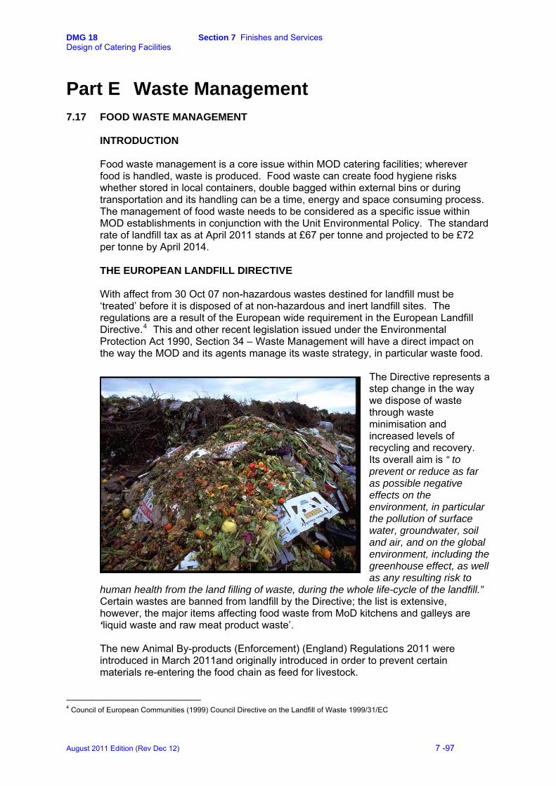
DMG 18 Section 7 Finishes and Services Design of Catering Facilities
Part E Waste Management 7.17 FOOD WASTE MANAGEMENT
INTRODUCTION Food waste management is a core issue within MOD catering facilities; wherever food is handled, waste is produced. Food waste can create food hygiene risks whether stored in local containers, double bagged within external bins or during transportation and its handling can be a time, energy and space consuming process. The management of food waste needs to be considered as a specific issue within MOD establishments in conjunction with the Unit Environmental Policy. The standard rate of landfill tax as at April 2011 stands at £67 per tonne and projected to be £72 per tonne by April 2014. THE EUROPEAN LANDFILL DIRECTIVE With affect from 30 Oct 07 non-hazardous wastes destined for landfill must be ‘treated’ before it is disposed of at non-hazardous and inert landfill sites. The regulations are a result of the European wide requirement in the European Landfill Directive.4 This and other recent legislation issued under the Environmental Protection Act 1990, Section 34 – Waste Management will have a direct impact on the way the MOD and its agents manage its waste strategy, in particular waste food.
The Directive represents a step change in the way we dispose of waste through waste minimisation and increased levels of recycling and recovery. Its overall aim is “ toprevent or reduce as far as possible negative effects on the environment, inthe pollution of surface water, groundwateand air, and on the global environment, including the greenhouse effect, as was any resulting risk to
human health from the land filling of waste, during the whole life
particular
r, soil
ell
-cycle of the landfill.”
Certain wastes are banned from landfill by the Directive; the list is extensive, however, the major items affecting food waste from MoD kitchens and galleys are ‘liquid waste and raw meat product waste’. The new Animal By-products (Enforcement) (England) Regulations 2011 were introduced in March 2011and originally introduced in order to prevent certain materials re-entering the food chain as feed for livestock.
4 Council of European Communities (1999) Council Directive on the Landfill of Waste 1999/31/EC
August 2011 Edition (Rev Dec 12) 7 -97

DMG 18 Section 7 Finishes and Services Design of Catering Facilities
Animal By-products (ABP’s) are divided into three categories according to the potential risk to human and animal health:
Category 1 Very High Risk (including catering waste from international transport)
Category 2 High Risk
Category 3 Low Risk – including: • Meat and fish from food manufacturing • Former foodstuffs of animal origin or containing
products of animal origin • Catering wastes • Eggs or other products that do not show signs of
infectious diseases • Milk • Fish or other sea animals • Shells • Hooves, horns and feathers
With regards to storage; the regulation states:
Storage of ABPs shall be kept separate, each category separated and separated from other waste streams
Must be stored in clean, leak proof containers labelled with the category
Containers shall be cleaned and disinfected after each emptying or collection
Must not be stored where they could contaminate other foodstuffs or be exposed to animals or birds
Food waste segregation will need to be considered including:
• Packaged or non packaged • Storage on site • Movement of waste around the site • Tipping and transfer • Cleaning and hygiene
Waste producers are not obliged to treat the waste themselves and may simply buy the service from a waste contractor, however, MOD Caterers do have a duty of care to ensure that waste is appropriately separated to allow the appointed waste contractors to comply with the regulations when taking waste to landfill. Several processing systems are available that may be operated locally, some of which are in use in MOD establishments.
August 2011 Edition (Rev Dec 12) 7 -98
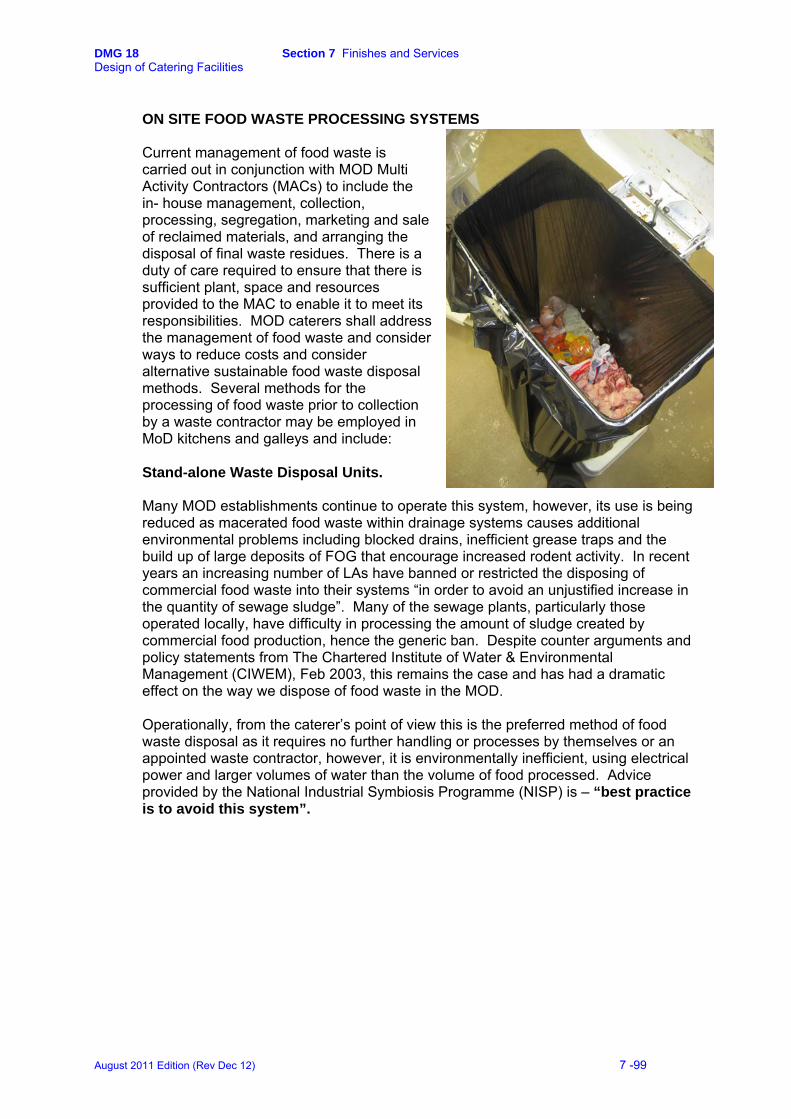
DMG 18 Section 7 Finishes and Services Design of Catering Facilities
ON SITE FOOD WASTE PROCESSING SYSTEMS Current management of food waste is carried out in conjunction with MOD Multi Activity Contractors (MACs) to include the in- house management, collection, processing, segregation, marketing and sale of reclaimed materials, and arranging the disposal of final waste residues. There is a duty of care required to ensure that there is sufficient plant, space and resources provided to the MAC to enable it to meet its responsibilities. MOD caterers shall address the management of food waste and consider ways to reduce costs and consider alternative sustainable food waste disposal methods. Several methods for the processing of food waste prior to collection by a waste contractor may be employed in MoD kitchens and galleys and include: Stand-alone Waste Disposal Units. Many MOD establishments continue to operate this system, however, its use is being reduced as macerated food waste within drainage systems causes additional environmental problems including blocked drains, inefficient grease traps and the build up of large deposits of FOG that encourage increased rodent activity. In recent years an increasing number of LAs have banned or restricted the disposing of commercial food waste into their systems “in order to avoid an unjustified increase in the quantity of sewage sludge”. Many of the sewage plants, particularly those operated locally, have difficulty in processing the amount of sludge created by commercial food production, hence the generic ban. Despite counter arguments and policy statements from The Chartered Institute of Water & Environmental Management (CIWEM), Feb 2003, this remains the case and has had a dramatic effect on the way we dispose of food waste in the MOD. Operationally, from the caterer’s point of view this is the preferred method of food waste disposal as it requires no further handling or processes by themselves or an appointed waste contractor, however, it is environmentally inefficient, using electrical power and larger volumes of water than the volume of food processed. Advice provided by the National Industrial Symbiosis Programme (NISP) is – “best practice is to avoid this system”.
August 2011 Edition (Rev Dec 12) 7 -99

DMG 18 Section 7 Finishes and Services Design of Catering Facilities
Waste Disposal Units combined with a De-watering system. Many installations in MOD kitchens and galleys employ this system in order to comply with local bye-law restrictions described above, however, it does present several operational problems and is not an efficient method of disposal. Food waste is
processed through maceration from where it is passed through a de-waterer that extracts up to 80% of the liquid from the macerated food mass. The liquid goes direct to drain as above, and the solids are collected for direct disposal to the refuse collection system. The solid food waste requires additional processing either by double bagging for forwarding to the refuse skips for subsequent collection by the appointed waste contractor, or further on site processing.
This system has generally not been
considered successful across the MOD, primarily due to insufficient volumes to operate effectively, complex installation requirements and difficulty in maintenance and cleaning. Double bagging Where there is no food waste process installed or a dewatering system is in place, food waste, including liquids, is currently double bagged and forwarded to the refuse skips for subsequent collection by the appointed waste contractor. This may include elements of general refuse such as paper, cardboard and plastics which does not comply with the requirements stated above. This is also a costly way of food waste disposal as invariably, it is by nature, very wet and therefore heavier per cubic metre. Additionally, further separation may have to be carried out which will inevitably result in additional costs to the contract. Vacuum food waste removal This system helps to meet the Landfill Directive by providing the means of sorting and storing food waste as a dedicated waste stream whilst reducing hygiene risks and the Health and Safety risks associated with the movement of heavy food waste within a catering facility. A recently introduced system aimed at the larger units, it operates by processing and transporting food waste from the point of disposal to a holding tank that can be located some distance away. Food waste is collected periodically by tanker vehicle and transferred to a treatment facility such as an anaerobic digestion plant, Biogas production, a renewable energy source or an automotive fuel. This system has already been installed in several new build facilities within the MOD. Whilst the initial capital costs are quite expensive and additional costs for the disposal transportation is required , the pay back period is approximately 5 years and does promote greater energy recovery from food waste via anaerobic digestion to capitalise on the potentially significant energy and carbon benefits. Locally, it provides for greater saving of water usage and as a stand-alone system does not add macerated food and FOG to the drainage system.
August 2011 Edition (Rev Dec 12) 7 -100
DMG 18 Section 7 Finishes and Services Design of Catering Facilities
Accelerated decomposition (Digestion) Relatively new to the UK, this system provides the means for the disposal of food waste directly to drain. The system operates in conjunction with a formula of micro organisms within a climatically controlled chamber that provides rapid and safe decomposition of food, the waste of which turns to water and is allowed to go to drain. The unit is available in several capacities that will suit both large and small kitchens. The advantages of the system include the reduction in landfill usage and cost, elimination of waste collection and transport costs with future proofing against increasing waste collection charges. This system is currently installed in several MOD kitchens and is proving a cost effective option against other methods and appears to satisfy most requirements. Being relatively new technology, recent installations are being monitored for performance.
In vessel composting
On site In Vessel Composting (IVC) systems are available in various types and sizes for on site usage adjacent to mess kitchens but does require daily care. The system is simple to operate with on-going production of quality organic compost, however, some systems, particularly the smaller units, may not always be ABP compliant. Food waste generally needs to be mixed with other green waste and card to attain satisfactory results. The system may require quite a large space with additional storage for card and green waste which will need to be considered; this may also attract vermin. The use of the compost produced would need to be identified.
Bio-drying
The system operates in a similar manner to IVC, can operate with a wide range of food types and volumes and can be sited within a small footprint. The output is in the form of pellets that may be sold or burned and would be suitable for some bio-mass boilers but may also be used as compost. The system needs to be managed carefully and will not accept any type of packaging. The output is thought to be generally ABP compliant.
August 2011 Edition (Rev Dec 12) 7 -101
DMG 18 Section 8 Combined Kitchens Design of Catering Facilities
8 Combined Kitchens
8.1 INTRODUCTION 8.2 PLANNING CONSIDERATIONS
August 2011 Edition (Rev Dec 12) 8 -99
DMG 18 Section 8 Combined Kitchens Design of Catering Facilities
8 Combined Kitchens
8.1 INTRODUCTION Consideration may be given to the option of providing a centralised kitchen to serve different messes whilst maintaining sound and visual segregation between the differing ranks. The principal is to reduce initial capital outlay and through–life costs and allow a reduction in the total number of kitchen staff required. Several areas may still require duplication and some circulation zones may need to be increased accordingly. The KDEA should be consulted with regard to the planning and design processes.
8.2 PLANNING CONSIDERATIONS
Where messes are combined, differing ranks normally require separate serveries and dining rooms in accordance with JSP 315 Scales 29, 34, 39 and 52. These facilities shall be segregated and each have its own separate entrance. The size of the kitchen and ancillary accommodation should be based on the total NTBF in the dependent messes. (See JSP 315, Scale 39, Part 2). Additional circulation space may be required for access to the separate serveries. The distances from the kitchen to the serveries should be kept to a minimum to allow the mess to function efficiently and to maintain communication between the dining room and the kitchen. Where possible, the design should allow for a single crockwash, sited to serve all messes and provide a logical workflow. Separate crockwashes may be required and is dependent on the individual mess requirements. Considerations for this may include siting constraints, messes operating on differing suites of crockery and cutlery, etc. The KDEA should be consulted. EQUIPMENT AND FITTINGS See JSP 315, Scale 39, Part 4 & Scale 52; Annexes B & D. FINISHES AND SERVICES See Section 7.
August 2011 Edition (Rev Dec 12) 8 -100
DMG 18 Section 9 Bars and Cellars Design of Catering Facilities
9 Bars and Cellars SECTION 9 BARS AND CELLARS 9.1 INTRODUCTION 9.2 PLANNING CONSIDERATIONS
August 2011 Edition (Rev Dec 12) 9 -101

DMG 18 Section 9 Bars and Cellars Design of Catering Facilities
9 Bars and Cellars
9.1 INTRODUCTION The storage and provision of alcoholic and non-alcoholic drinks are subject to the same food hygiene regulations as for food. Bar facilities are normally provided within the mess for Officers and SNCOs and should be provided in accordance with JSP 315, Scales 29 and 34. Junior ranks are normally provided with bar facilities within the dedicated leisure areas. The CRL concept provides for the Junior Ranks' leisure and social facilities to be provided within, or immediately adjacent to the messing facilities, to provide a combined social centre. Designers should take account of the functional relationships between the various areas provided for dining, social and leisure activities.
9.2 PLANNING CONSIDERATIONS BARS
The bar servery is a food room and as such should be designed to ensure an efficient workflow, fitted out with smooth, impervious fixtures and fittings to enable ease of cleaning. Adequate hot and cold water supply is to be provided for hand washing and the washing and sanitisation of glasses. Glass washing facilities may be provided by a dedicated glass washing machine, with the ability to provide sanitisation, supported by a sink with draining board. Sufficient space should be provided for the collection of dirty glasses and air drying/cooling space for clean glasses. Hand wash facilities should be separate with provision of a bactericidal soap dispenser and paper towel holder. Adequate ventilation shall be provided within the bar servery area and balanced to ensure that the air is drawn away from the servery into the public area. The run of beer pipes (Python) from the beer store to the bar dispense heads shall be installed to provide ease of access and cleaning to all parts. Any trenches or penetration points into food rooms shall be adequately sealed. Bar counters shall be manufactured to DE Specification 42 – Catering Equipment Specification - CES 51. Where kegs are dispensed directly from the bar area, provision should be made for the restraint of gas cylinders. A security grill/shutter along the full length of the counter shall be fitted according to the particular design requirements.
August 2011 Edition (Rev Dec 12) 9 -102
DMG 18 Section 9 Bars and Cellars Design of Catering Facilities
CELLARS AND STORAGE The beer store (cellar) is a food room and as such should be designed to ensure an efficient workflow and be fitted out with smooth, impervious fixtures and fittings to enable ease of cleaning. The beer store and the empties store should be sited adjacent to the service yard/delivery area and be suitably protected from ingress of pests. The cellar is to be close to the bar to ensure minimum pipe runs from the kegs and barrels to the service heads. Where kegs, real ales and bottled drinks are stored, the cellar shall be cooled to ensure that products are stored and dispensed at their optimum service temperature. Alternatively, provision may be made for the installation of an in-line chilled python system. Adequate hot and cold water supply is to be provided for the washing and sterilisation of dispensing equipment. A cold water point should be additionally provided for the hosing down of the cellar area. A treated, potable water supply shall be installed to an ice machine. Suitable drainage shall be provided to all equipment and comply with the details within Section 7.7. A trapped, dished floor gully is to be installed to allow adequate drainage. Adequate ventilation should be provided to prevent the build up of moulds and yeast spores on walls and ceilings and meet with the air changes requirements of manufacturer’ installed service equipment. Electrical installations shall be appropriately IP-rated as required by the particular room data specification. Adequate provision should be made for the storage and restraint of gas cylinders. A separate general store area should be provided for the storage of ancillary bar items. All storage areas shall be provided with suitable security locks to the doors and additional security to any external windows etc. EQUIPMENT AND FITTINGS See JSP 315, Scales 29, 34 and 52 and DE Specification 42 – Catering Equipment Specification.
August 2011 Edition (Rev Dec 12) 9 -103
DMG 18 Section 9 Bars and Cellars Design of Catering Facilities
FINISHES (See also Section 7) The general principles of the finishes and services apply as in Section 7 in that the layout, design and construction of bars, bar cellars and storage areas are fitted with smooth, impervious, hygienic surfaces that shall permit adequate cleaning and/or disinfection, and generally meet the requirements defined in the Food Hygiene (England) (No.2) Regulations 2006. (Regulation (EC) No.852/2004)1
Floors Floors behind bar counters shall generally be finished with non-flammable vinyl sheet. The principles of finish, specification and installation shall be as described at Section 7.2 with the exception that a 2.5 mm thickness may apply. Floor finishes in cellar storage areas should allow for the frequent movement of kegs and barrels, each weighing 50kg. The standard installation may be of smooth finished concrete sealed with a concrete hardener and/or epoxy resin floor paint. Alternatively, a heavy duty epoxy resin bonded floor system may be considered for particularly heavily used areas. Walls Finishes to walls behind bar service counters may complement the surrounding bar décor, however, they should retain the principles of the food hygiene regulations. Wall finishes should follow the principles stated at Section 7.3, however, the general requirement is for an epoxy resin coating applied direct to a plastered wall. This may also be applied directly to a sealed breeze block finish, however, this should only be considered where the finish of the block is smooth. Stainless steel sheeting may be provided to the lower levels as a finish and additional protection from damage. Wall protection as defined at Section 7.3 shall be fitted at mid-height, low level and external corners to prevent damage within the bar cellar and the delivery route from the goods inwards door to the storage location. Ceilings Ceilings behind bar servery areas should be of a washable painted plastered finish rather than a suspended ceiling. Ceilings in bar cellar areas may have a painted plaster finish or suspended metal pan-tiles. An epoxy resin coating shall be applied direct to a plastered ceiling to prevent the formation of mould spores etc. Doors The provision of doors shall follow the detail provided at Section 7.5. All doors associated with access to the bar or bar storage areas shall be lockable.
1 (and equivalent regulations in Scotland, Wales and Northern Ireland)
August 2011 Edition (Rev Dec 12) 9 -104
DMG 18 Section References Design of Catering Facilities
References Publications that may be read in conjunction with this guide excluding references to Building Regulations and associated Service installation regulations include: FOOD SAFETY AND HEALTH & SAFETY
The Food Safety Act 1990 Food Safety (General food Hygiene) Regulations 1995 Health & Safety at Work Act 1974 and its derivatives including; The Workplace (Health, Safety and Hygiene) Regulations 1992 The Management of Health & Safety at Work Regulations 1992 The Provision and Use of Work Equipment Regulations 1992 The Personal Protective Equipment at Work Regulations 1992 The Health & Safety (Display Screen Equipment) Regulations 1992 The Manual Handling Operations Regulations 1992 The Industry Guide to Good Hygiene Practice – Catering Guide The Animal By-Products Regulations 2003 The Food Hygiene (England) (No.2) Regulations 2005. (Regulation (EC) No.852/2004 on the hygiene of foodstuffs)
ENERGY MANAGEMENT AND CONSERVATION
The Government Strategic Energy Plan MOD/DETR Energy Consumption Guide 75 DETR Good Practice Guide 222 Energy Conservation Act 1981 CIBSE Energy Code
DEFENCE INFRASTRUCTURE ORGANISATION PUBLICATIONS
Design & Maintenance Guides DMG 07 - Justifying the Provision of Air Conditioning DMG 08 - Space Requirement for Plant Access, Operation & Maintenance DMG 15 - Safety Devices for Cold Rooms DMG 17 - Design Energy Targets DMG 22 - Building Energy Management Systems Joint Services Publication JSP 315 Services Accommodation Code Volumes 1 and 3 Buildings, Design & Construction Design Excellence Evaluation Process (DEEP) General All relevant Technical Bulletins
August 2011 Edition (Rev Dec 12)
DMG 18 Section References Design of Catering Facilities
Specifications Specification 05 - Property Management of the Defence Estate Specification 14 - Typical Estate Maintenance Policy Statement & Guidelines Specification 36 - Heating, Hot & Cold Water, Steam & Gas Installations Specification 37 - Air Conditioning, Air Cooling & Mechanical Ventilation Specification 38 - Hygienic Cleaning of Food Rooms & Catering Equipment Specification 42 - Catering Equipment Specification Specification 47 - Building Energy Management Systems
OTHER PUBLICATIONS
Food Research Organisation-TM44 Guidelines for the Design & Construction of Walls, Ceilings & Services for Food Production Areas Food Research Organisation- Guidelines for the Design & Construction of Floors for Food Preparation Areas. HVCA Specification for Kitchen Ventilation Systems HVCA Guide to Good Practice for Internal Cleanliness of Ventilation Systems New Metric Handbook – Planning & Design Data (Tett & Adler)
August 2011 Edition (Rev Dec 12)
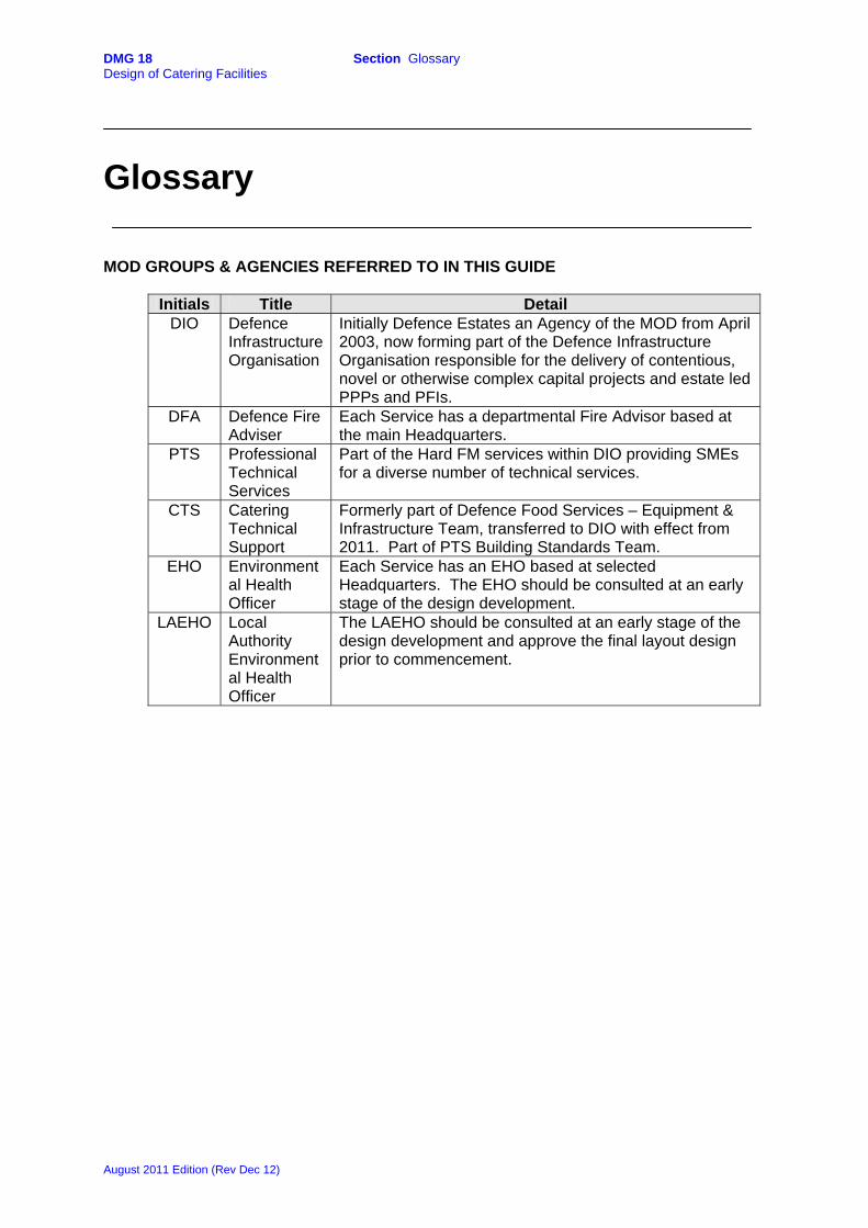
DMG 18 Section Glossary Design of Catering Facilities
Glossary MOD GROUPS & AGENCIES REFERRED TO IN THIS GUIDE
Initials Title Detail DIO Defence
Infrastructure Organisation
Initially Defence Estates an Agency of the MOD from April 2003, now forming part of the Defence Infrastructure Organisation responsible for the delivery of contentious, novel or otherwise complex capital projects and estate led PPPs and PFIs.
DFA Defence Fire Adviser
Each Service has a departmental Fire Advisor based at the main Headquarters.
PTS Professional Technical Services
Part of the Hard FM services within DIO providing SMEs for a diverse number of technical services.
CTS Catering Technical Support
Formerly part of Defence Food Services – Equipment & Infrastructure Team, transferred to DIO with effect from 2011. Part of PTS Building Standards Team.
EHO Environmental Health Officer
Each Service has an EHO based at selected Headquarters. The EHO should be consulted at an early stage of the design development.
LAEHO Local Authority Environmental Health Officer
The LAEHO should be consulted at an early stage of the design development and approve the final layout design prior to commencement.
August 2011 Edition (Rev Dec 12)