Embed Size (px)
Citation preview
Design and Fabrication of Automatic Rocker
ARM Feeding Mechanism using Compressed Air
R. S. Dayanidhi (1)
, S. P. Archana (2)
, R. Jayashruthi (3)
,
V. Arul (4) Dr. S. Santhana Krishnan(5)
Department of Mechanical Engineering,
Meenakshi Sundararajan Engineering College,
Tamil Nadu, India.
Abstract - Nowadays there are many efforts being
made for taking away the burden on the human.
For this purpose there are many efforts going on for
the Atomization of machines. This report taken up
the fabrication of “Automatic rocker arm feeding
mechanism using the compressed air” this machine
automatically feeds its stock and performs the
cutting operation. It involves simple mechanism.
Here the main objective is the power input from the
industrial exhaust gases, which is given to the
engine. When the piston actuates inside the cylinder
the reciprocating motion convert into rotary
motion. These rotaries motion given as input to the
feeding mechanism by using the belt. This
mechanism is handy in making holes on metal sheets
in industries, by changing tool various actions can
be performed.
Keywords – Cylinder, Piston, Belt, Metal sheets.
INTRODUCTION
Mechanical engineering without production and
manufacturing is meaningless and inspirable. Production
and manufacturing process deals with conversion of raw
materials inputs to finished products as per required
dimensions and efficiently using recent technology. Now a
days machines are widely controlled by embedded system,
to meet the need of exploding population economic and
effective control of machines is necessary the main theme
of our project is sed to feed the raw material automatically
to the machine And make the holes simultaneously with a
particular gap. A mechanism is considered to be more
general. It is an isolated group of rigid bodies through the
study of which we can understand the basic structure of any
machine and can design machines that are not in existence.
Whenever there is a need for motion accompanied with
force, there is a mechanism
A system that consists of links & joints and converts one
form of motion to another form is called as Mechanism.
Mechanism is a combination of rigid bodies which are
formed and connected together by links, so that they are
moved to perform some functions, such as the crank
connecting rod mechanism of the I.C. engines, mechanisms
of automobiles etc. A mechanism is considered to be more
general. It is an isolated group of rigid bodies through the
study of which one can understand the basic structure of
any machine and can design machines that are not in
existence.
Whenever there is a need for motion accompanied with
force, there is a mechanism. A group of rigid bodies
connected to each other by rigid kinematic pairs (joints) to
transmit force and motion. A machine consists of a
number of parts or bodies, the mechanism of the various
parts or bodies from which the machine is assembled. This
is done by making one of the parts fixed, and the relative
motion of other parts is determined with respect to the
fixed part..
Kinematic Element:Kinematic element is a part of a rigid body which is used
to connect it to another rigid body such that the relative
motion between the two rigid bodies can occur.
KINEMATIC PAIR:
Kinematic pairs the joining of two kinematic elements.
The types of kinematic pairs and their distribution within
the mechanism determine the main characteristics of a
mechanism. The relative motion between the kinematic
pair is completely or successfully constrained(i.e. in a
definite direction).Links are rigid bodies each having
hinged holes or slot to be connected together by some
means to constitute a mechanism which able to transmit
motion or forces to some another locations
PROBLEM IDENTIFICATION
Hand operated punching and feeding has many advantages
and disadvantages , like hand feeding has accuracy and job
availability but due to late work complete, accident and
high cost, alternate source of operation started.Individual
power is required to feed and puching, stamping etc…to
overcome this exhaust air will be used to run the feeding
mechanism
International Journal of Engineering Research & Technology (IJERT)
ISSN: 2278-0181http://www.ijert.org
IJERTV8IS080144(This work is licensed under a Creative Commons Attribution 4.0 International License.)
Published by :
www.ijert.org
Vol. 8 Issue 08, August-2019
353
,
A. OBJECTIVES:
• To save electricity
• Reuse the exhaust gases from the industries to mechanical
work
• Simple feeding mechanism used for small scale industries
• Now a day, machines are widely controlled by embedded
system. To meet the need of exploding population
economic and effective control of machines is necessary.
• The main theme is used to feed the raw material
automatically to the machine and make holes
simultaneously with a particular gap.
• To decrease the mistakes made by human. To increase the
accuracyB. SPECIFICATION:
Diameter of the cylinder (d)= 25mm
Stroke length(L)= 80mm
Diffuser inlet diameter (d1)= 10mm
Diffuser outlet diameter (d2)= 25mm
Diameter of the piston(d*)= 23mm
Pressure (P)= 2 BAR= 2*10^5 N/M^2
Link 5
Length of the rocker arm = 150mm
Width of the rocker arm = 80
Thickness of the rocker arm = 5mm
Links (1,2,3)
Length= 250mm
Width = 50mm
Thickness = 5mm
Link 4
Length= 200mm
Width = 50mm
Thickness = 5mm
Base 300mm*600 mm(1feet*2feet)
Drill holes = 8mm,8mm,6mm
Nut & bolt = M8,M10,M6
C. FORMULA USED:
INDICATED POWER:
IP= Pm*l*A*N*K
60
Where,
Pm = Mean effective pressure(N/m2)
L = Stroke length(m)
A = Area of cylinder(m2)
Where,
A =/4 d^2
d= diameter of cylinder (m) N = Speed ( rpm)
K = No of cylinder
BRAKE POWER:
BP= 2 NT
60
Where,
T= WxR
Where
W= Tangential force (or) force acting on the piston (N)
T= Twisting moment(NM)
R= Radial distance of wheel (m)
Where,
W= Pxd2 / 4
where
P= Pressure inside cylinder (N/m2) D = diameter of
cylinder (m)
Efficiency
=IP/BP*100
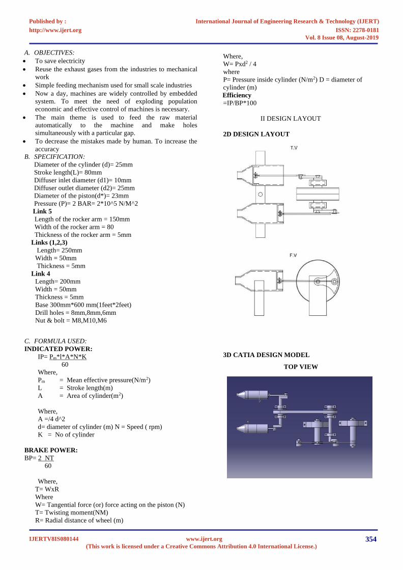
II DESIGN LAYOUT
2D DESIGN LAYOUT
3D CATIA DESIGN MODEL
TOP VIEW
International Journal of Engineering Research & Technology (IJERT)
ISSN: 2278-0181http://www.ijert.org
IJERTV8IS080144(This work is licensed under a Creative Commons Attribution 4.0 International License.)
Published by :
www.ijert.org
Vol. 8 Issue 08, August-2019
354

FRONT VIEW
SIDE VIEW
PROJECTIONAL VIEW
III DESIGN CALCULATION
INDICATED POWER :
IP= Pm*l*A*N*K
60
Pm= 2 X 10⁵ (N/m2)
L= 0.08 (m)
A= 4.908 x 10⁻⁴(m2) N = 100 ( rpm)
K = 2
IP= 2x105 x 0.08 x 4.908x10-4 x 100 x 2
60
IP = 26.179 W
BRAKE POWER
BP= 2 NT
60
Where
T= WxR
W= 31.25 (N)
R= 0.06 (m)
T= 31.25 x 0.06
T=1.875
BP= = 2 x 100 x 1.875
60
BP=19.634 W
EFFICIENCY
mech = BP/IP*100
19.634
26.179
0.7499 x 100
mech = 74 %
International Journal of Engineering Research & Technology (IJERT)
ISSN: 2278-0181http://www.ijert.org
IJERTV8IS080144(This work is licensed under a Creative Commons Attribution 4.0 International License.)
Published by :
www.ijert.org
Vol. 8 Issue 08, August-2019
355

A. GRAPH: BRAKE POWER VS INDICATED POWER
IV MATERIAL SELECTION
A. AVAILABLITY AND COST:
To prepare any machine part, the type of material should be
properly selected, considering design, safety and following
points. The selection of material for engineering application is
given by the following factors:-
1. Availability of materials
2. Suitability of the material for the required components.
3. Suitability of the material for the desired working
conditions.
4. Cost of materials.
B. PROPERTIES
V MANUFACTURING PROCESS
A. WELDING:
Arc welding is a welding process that is used to join metal to
metal by using electricity to create enough heat to melt metal,
and the melted metals when cool result in a binding of the
metals. It is a type of welding that uses a welding power supply
to create an electric arc between a metal stick ("electrode") and
the base material to melt the metals at the point of contact. Arc
welders can use either direct (DC) or alternating (AC) current,
and consumable or non-consumable electrodes.
S. No Mech. Properties Symbol Units Mild steel
1. Young’s Modulus E Gpa 105.0
2. Shear Modulus G Gpa 36.75
3. Poisson Ratio v -------- 0.23
4. Density Kg/m³ 7209
5. Yield Strength Sy Mpa 130
6. Shear Strength Ss Mpa 169
The welding area is usually protected by some type of shielding
gas, vapor, or slag. Arc welding processes may be manual,
semi-automatic, or fully automated. First developed in the late
part of the 19th century, arc welding became commercially
important in shipbuilding during the Second World War. Today
it remains an important process for the fabrication of steel
structures and vehicles.
International Journal of Engineering Research & Technology (IJERT)
ISSN: 2278-0181http://www.ijert.org
IJERTV8IS080144(This work is licensed under a Creative Commons Attribution 4.0 International License.)
Published by :
www.ijert.org
Vol. 8 Issue 08, August-2019
356
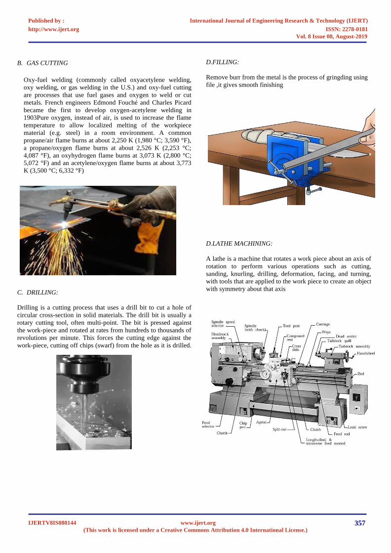
B. GAS CUTTING
Oxy-fuel welding (commonly called oxyacetylene welding,
oxy welding, or gas welding in the U.S.) and oxy-fuel cutting
are processes that use fuel gases and oxygen to weld or cut
metals. French engineers Edmond Fouché and Charles Picard
became the first to develop oxygen-acetylene welding in
1903Pure oxygen, instead of air, is used to increase the flame
temperature to allow localized melting of the workpiece
material (e.g. steel) in a room environment. A common
propane/air flame burns at about 2,250 K (1,980 °C; 3,590 °F),
a propane/oxygen flame burns at about 2,526 K (2,253 °C;
4,087 °F), an oxyhydrogen flame burns at 3,073 K (2,800 °C;
5,072 °F) and an acetylene/oxygen flame burns at about 3,773
K (3,500 °C; 6,332 °F)
D.FILLING:
Remove burr from the metal is the process of gringding using
file ,it gives smooth finishing
D.LATHE MACHINING:
A lathe is a machine that rotates a work piece about an axis of
rotation to perform various operations such as cutting,
sanding, knurling, drilling, deformation, facing, and turning,
with tools that are applied to the work piece to create an object
with symmetry about that axisC. DRILLING:
Drilling is a cutting process that uses a drill bit to cut a hole of
circular cross-section in solid materials. The drill bit is usually a
rotary cutting tool, often multi-point. The bit is pressed against
the work-piece and rotated at rates from hundreds to thousands of
revolutions per minute. This forces the cutting edge against the
work-piece, cutting off chips (swarf) from the hole as it is drilled.
International Journal of Engineering Research & Technology (IJERT)
ISSN: 2278-0181http://www.ijert.org
IJERTV8IS080144(This work is licensed under a Creative Commons Attribution 4.0 International License.)
Published by :
www.ijert.org
Vol. 8 Issue 08, August-2019
357
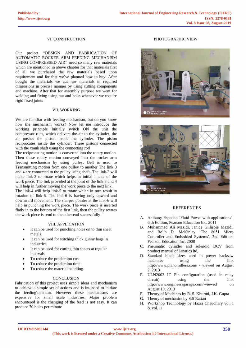
VI. CONSTRUCTION
Our project “DESIGN AND FABRICATION OF
AUTOMATIC ROCKER ARM FEEDING MECHANISM
USING COMPRESSED AIR” need so many raw materials
which are mentioned in above chapter for that materials first
of all we purchased the raw materials based upon
requirement and for that we’ve planned how to buy. After
bought the materials we cut raw materials in required
dimensions in precise manner by using cutting components
and machine. After that for assembly purpose we went for
welding and fixing using nut and bolts whenever we require
rigid fixed joints
VII. WORKING
We are familiar with feeding mechanism, but do you know
how the mechanism works? Now let me introduce the
working principle Initially switch ON the unit the
compressor runs, which delivers the air to the cylinder, the
air pushes the piston inside the cylinder. The piston
reciprocates inside the cylinder. These pistons connected
with the crank shaft using the connecting rod
The reciprocating motion is converted into the rotary motion
Then these rotary motion conveyed into the rocker arm
feeding mechanism by using pulley. Belt is used to
Transmitting motion from one pulley to another The link 3
and 4 are connected to the pulley using shaft. The link-3 will
make link-2 to rotate which helps in initial intake of the
work piece. The link provided at the joint of the link 3 and 4
will help in further moving the work piece to the next link.
The link-4 will help link-5 to rotate which in turn result in
rotation of link-6. The link-6 is having only upward and
downward movement. The sharper pointer at the link-6 will
help in punching the work piece. The work piece is inserted
flatly in to the bottom of the first link, then the pulley rotates
the work piece is send to the other end successfully
VIII. APPLICATION
• It can be used for punching holes on to thin sheet
metals.
• It can be used for stitching thick gunny bags in
industries.
• It can be used for cutting thin sheets at regular
intervals
• To reduce the production cost
• To reduce the production time
• To reduce the material handling.
CONCLUSION
Fabrication of this project uses simple ideas and mechanism
to achieve a simple set of actions and is intended to initiate
the feeding\operator. However these mechanisms are
expensive for small scale industries. Major problem
encountered is the changing of the feed is not easy. It can
produce 70 holes per minute
PHOTOGRAPHIC VIEW
REFERENCES
A. Anthony Esposito ‘Fluid Power with applications’,
6 th Edition, Pearson Education Inc. 2011
B. Muhammad Ali Mazidi, Janice Gillispie Mazidi,
and Rolin D. McKinlay ‘The 8051 Micro
Controller and Embedded Systems’, 2nd Edition,
Pearson Education Inc. 2008
C. Pneumatic cylinder and solenoid DCV from
product manual of Janatics ltd,
D. Standard blade sizes used in power hacksaw
machines using the link
http://www.planomillers.com/ - viewed on August
2, 2013
E. ULN2003 IC Pin configuration (used in relay
circuit) using the link
http://www.engineersgarage.com/-viewed on
August 10, 2013
F. Theory of Machines by R. S. Khurmi, J.K. Gupta
G. Theory of mechanics by S.S Rattan
H. Workshop Technology by Hazra Chaudhary vol. I
& vol. II
International Journal of Engineering Research & Technology (IJERT)
ISSN: 2278-0181http://www.ijert.org
IJERTV8IS080144(This work is licensed under a Creative Commons Attribution 4.0 International License.)
Published by :
www.ijert.org
Vol. 8 Issue 08, August-2019
358
1. M.Rethish ,S.Sujithbeno ,S.Ramkumar
,S.Sanjeev ,K.Chandrasekar
“AUTOMATIC SUSPENSION USING
ROCKER BOGIE MECHANISM”,
INTERNATIONAL JOURNAL FOR
RESEARCH & DEVELOPMENT IN
TECHNOLOGY Volume-7,Issue-4, (April-
17).
2. Prof. Sabry A. El-Shakery, Dr. Khaled. M.
Khader,”Optimal Synthesis of Crank-
Rocker Mechanism with Unit Time Ratio
and Desired Equal Deviation of Minimax
Transmission Angle”, International Journal
of Advanced Engineering and Global
Technology Vol-03, Issue-09, September
2015.
3. C.HChiang “ Design of spherical and
planar crank-rockers and double-
rockers as function generators—
IKonstrukton sphärischer und ebener
kurbelschwingen und doppelschwingen
als funktionsgetriebe–I.
kurbelschwingen: Crank-Rockers”,
ELSEVIER Mechanism and Machine
Theory Volume 21, Issue 4, 1986, Pages
287- 296.
International Journal of Engineering Research & Technology (IJERT)
ISSN: 2278-0181http://www.ijert.org
IJERTV8IS080144(This work is licensed under a Creative Commons Attribution 4.0 International License.)
Published by :
www.ijert.org
Vol. 8 Issue 08, August-2019
359


![INDEX []ROCKER ARM ASSY 9 KV74008BA ロツカ- プレ-ト 1 PLATE,ROCKER 10 KV72012AA ロツカア-ム 1 ARM,ROCKER 11 KV72013AA ロツカア-ム 1 ARM,ROCKER 12 KU23013AA ナツト](https://img.dokumen.tips/doc/110x75/5fde9bd37e867c36f63083d2/index-rocker-arm-assy-9-kv74008ba-iii-ioeii-i-1-platerocker-10.jpg)