Embed Size (px)
Citation preview
DESIGN AND FABRICATION OF A GLOVEBOX FOR THE PLASMA HEARTH PROCESS RADIOACTIVE BENCH-SCALE SYSTEM
Dale R. Wahlquist
Technology Development Division Argonne National Laboratory - West
P.O. Box 2528 Idaho Falls, ID 83403 Phone (208) 533-7580 Fax (208) 533-7151
e-mail: [email protected]
Submitted to the
“American Glovebox Society 10th Annual Conference”
San Diego, California July 22-25, 1996
by a contractor of the U. S. Government under contract No. W-31-104ENG-38. Accordingly, the U. S. Government retains a nonexclusive, royalty-free license to publish or reproduce the published form of this contribution, or allow others to do SO. for

DISCLAIMER
Portions of this document may be illegible in electronic image products. Images are produced from the best available original document.

Dale R Wahlquist Technology Development Division Argonne National Laboratory - West Idaho Falls, ID 83403
DESIGN A N D FABRICATION OF A GLOVEBOX FOR THE PLASMA HEARTH PROCESS RADIOACTIVE BENCH-SCALE SYSTEM
Abstract: This paper presents some of the design considerations and fabrication techniques for building a glovebox for the Plasma Hearth Process (PHP) Radioactive Bench-Scale System. The PHP Radioactive Bench-Scale System uses a plasma torch to process a variety ofradioactive materials into a find vitrified waste form. The processed waste will contain plutonium and trace amounts of other radioactive materials. The glovebox used in this system is located directly below the plasma chamber and is called the Hearth Handling Enclosure (HHE). The HHE is designed to maintain a confmement boundary between the processed waste and the operator. Operations that take place inside the HHE include raising and lowering the hearth using a hydraulic lift table, transporting the hearth within the HHE using an overhead monorail and hoist system, sampling and disassembly of the processed waste and hearth, weighing the hearth, rebuilding a hearth, and sampling HEPA Hters. The PHP Radioactive Bench- Scale System is located at the TREAT facility at Argonne National Laboratory-West in Idaho Falls, Idaho.
INTRODUCTION
The Hearth-Handling Enclosure (HHE) is part of the primary-confinement boundary for the Plasma Hearth Process (PHP) Radioactive Bench-Scale System. The PHP Radioactive Bench-Scale System is a one year demonstration project designed to process mixed hazardous radioactive waste into a final vitrified and non-leachable waste form. The Plasma Hearth processes eight one gallon cans of waste per batch run. The cans are fed into the plasma chamber where they are melted by the plasma torch and deposited in the hearth. The hearth is a refractory lined crucible 46" in diameter, 13" high and weighs up to 2400 lbs. The processed waste will be sampled to determine the amount of plutonium and other radioactive isotopes in the slag material. The HHE was designed primarily to provide a containment area for disassembly and reassembly of the hearth. The PHP Radioactive Bench-Scale System is located at the TREAT facility at Argonne National Laboratory-West in Idaho Falls, Idaho.
DESIGN AND PERFORMANCE CONSIDERATIONS
At the beginning of every design project, there are certain design and performance considerations that must be taken into account. Questions one might consider are; where will the glovebox be located, what are the electrical power requirements, what material is being contained inside the glovebox, what are the interfaces, what equipment is needed to support the operations, etc. Below is a brief list of some of the items considered important to the design of the HHE. d<
,. ,
The HHE must:
be an alpha-tight enclosure. be equipped with a scale capable of weighing a hearth (2400 Ibs.). contain a large transfer port capable of transferring a hearth and a small transfer port for transferring samples and small tools. be equipped with an overhead lifting device capable of lifting a hearth and transferring it to different work stations inside the HHE. incorporate human-factors design concepts to enhance the safety of operations personnel involved in materials handling. contain equipment capable of extracting samples from the processed material. be maintained at a minimum negative differential pressure of 0.3" to 0.8" w.g. with respect to the process room. have internal fire protection. be equipped with a lifting device capable of raising and lowering the hearth and plasma chamber base plate (combined weight of 4500 Ibs.) interface with the Plasma Chamber (60" in dia., 9' above floor level). include an access door for non-routine manned entries
SYSTEM DESCFUPTION
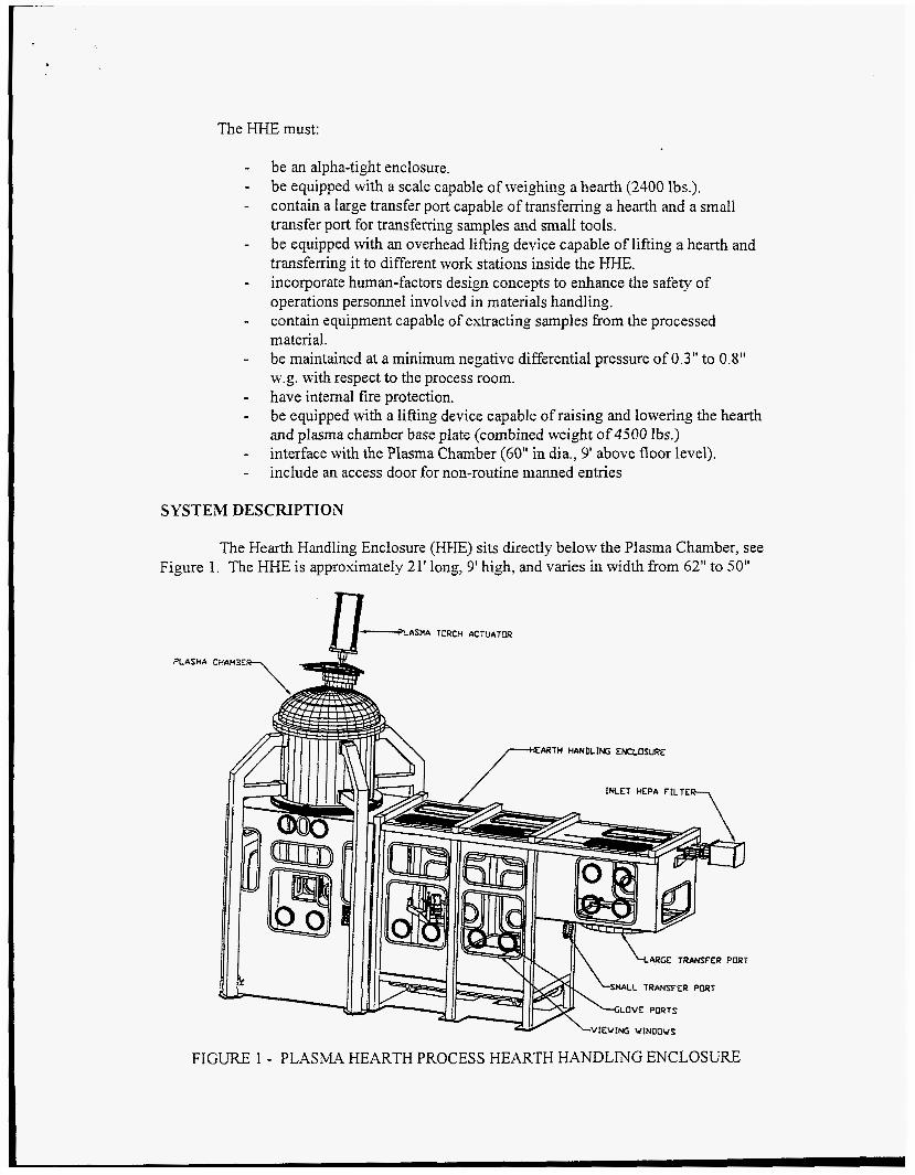
The Hearth Handling Enclosure (HHE) sits directly below the Plasma Chamber, see Fi,gre 1. The HHE is approximately 2 1' long, 9' high, and varies in width from 62" to 50"
PLASMA
AsnA TORCH ACTUP~TCR
CHAHSE7
LVIEVING VINOOVS
FIGURE 1 - PLASMA HEARTH PROCESS HEARTH HANDLING ENCLOSURE

along its length. The HHE shell is made with 1/8" thick stainless-steel plates supported by a framework of 4" x 4" x 114" carbon steel structural tubing on the exterior. The floor of the Slovebox has %" or 314" thick S . S . plates and 1/4" thick S.S. vertical plates on the ends of the glovebox to provide additional stiffening. The HHE was designed with the equipment and systems indicated below in order to meet the design and performance requirements.
Ventilation system - The HHE operates at a minimum differential air pressure (DP) of 0.3 inches w.g. negative and a masimum DP of 0.8 inches w.g. negative with respect to the process room. A Iow-pressure alarm sounds if the DP falls below 0.3 in. w.g. The ventilation system is capable of maintaining an air velocity of 125 ftlmin across the most credible opening in the event of a breach in confinement. The HHE has one HEPA-filtered inlet and two HEPA filters on the outlet.
Illumination - The HHE is equipped with six 2' X 2' and one 1' X 4' exterior fluorescent lights that illuminate the HHE interior through several different sized windows in the roof and sides of the enclosure.
Viewing Ports - There are 28 3/8" thick safety-glass windows of various sizes located around the perimeter of the enclosure. The window glass was laminated per ASTM C 1 172-91, from 2 lites of Kind LA, Type 1, Class 1, q3-quality glass. The windows are held in place using the "zippered" type rubber molding.
Fire Protection - Fire protection is provided inside the HHE by two water sprinkler heads. The sprinkler heads are connected to the facility's fire sprinkler system and are set to automatically turn on when the temperature at the head reaches 1650 F and turn off at 155. F. The HHE includes a drain port for draining the fire water.
Access and Transfer Ports - There are two 8" diameter glove ports at each norkstation of the HHE for a total of 24 glove ports. The glove ports are equipped with removable covers on the exterior of the enclosure. The ambidextrous gloves are 32" long and are made of 0.030" thick neoprene.
There is a removable sealed door in the HHE to facilitate initial equipment installation and for suited personnel entries during non-routine maintenance.
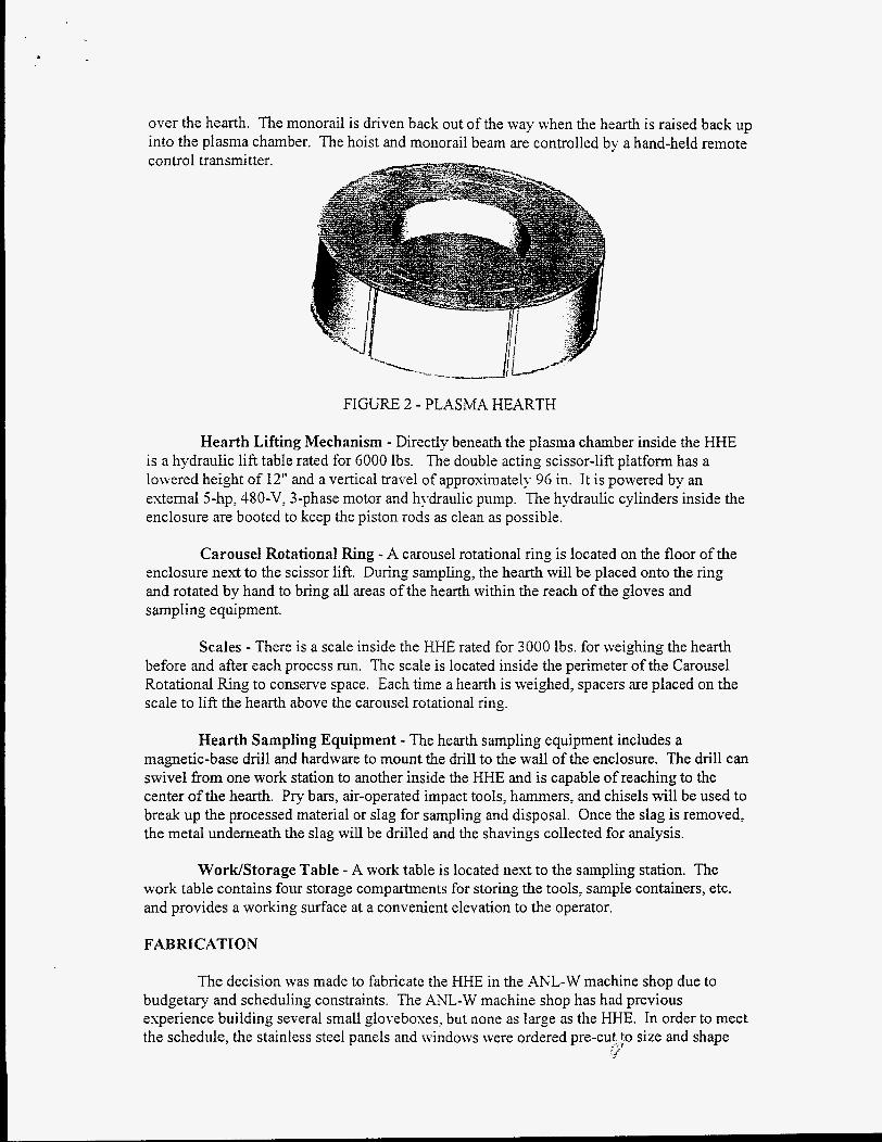
There are two transfer ports attached to the enclosure, see Figure 1. The large transfer port is 48" in diameter and the small transfer port is 8" in diameter. The large transfer port is used to transfer processed material out of the HHE and to transfer new refractory (brick) into the HHE. For each process batch, as much as 1200 Ibs. of refractory will be transferred through the large transfer port for disassembly and reassembly of the hearth, see Figure 2. The small transfer port is used to transfer samples out of the HHE and to transfer tools and sampling materials into the HHE. Both transfer ports are located inside the transfer room. The transfer room provides an additional layer of contamination control specifically for the bagging operations.
Overhead Handling Equipment - Mounted inside the roof of the HHE is a traveling-beam monorail with an electric hoist. The hoist is a low-headroom design and is rated for 3000 lbs. The hoist has sufficient travel to raise and lower a hearth from the plasma chamber base plate and also to transfer it through the large transfer port if necessary. The traveling beam monorail is externally motor driven and is used to position the hoist directly -3
over the hearth. The monorail is driven back out of the way when the hearth is raised back up into the plasma chamber. The hoist and monorail beam are controlled by a hand-held remote control transmitter.
FIGURE 2 - PLASMA HEARTH
Hearth Lifting Mechanism - Directly beneath the plasma chamber inside the HHE is a hydraulic lift table rated for 6000 Ibs. The double acting scissor-lift platform has a lowered height of 12" and a vertical travel of approximately 96 in. It is powered by an external j-hp, 4XO-V, 3-phase motor and hydraulic pump. The hydraulic cylinders inside the enclosure are booted to keep the piston rods as clean as possible.
Carousel Rotational Ring - A carousel rotational ring is located on the floor of the enclosure next to the scissor lift. During sampling, the hearth will be placed onto the ring and rotated by hand to bring all areas of the hearth within the reach of the gloves and sampling equipment.
Scales - There is a scale inside the HHE rated for 3000 Ibs. for weighing the hearth before and after each process run. The scale is located inside the perimeter of the Carousel Rotational Ring to conserve space. Each time a hearth is weighed, spacers are placed on the scale to lift the hearth above the carousel rotational ring.
Hearth Sampling Equipment - The hearth sampling equipment includes a magnetic-base drill and hardware to mount the drill to the wall of the enclosure. The drill can swivel fiom one work station to another inside the HHE and is capable of reaching to the center of the hearth. Pry bars, air-operated impact tools, hammers, and chisels will be used to break up the processed material or slag for sampling and disposal. Once the slag is removed, the metal underneath the slag will be drilled and the shavings collected for analysis.
WorWStorage Table - A work table is located nest to the sampling station. The work table contains four storage compartments for storing the tools, sample containers, etc. and provides a working surface at a convenient elevation to the operator.
FABRICATION
The decision was made to fabricate the HHE in the ANL-W machine shop due to budgetary and scheduling constraints. The ANL-W machine shop has had previous experience building several small gloveboses, but none iis large as the HHE. In order to meet the schedule, the stainless steel panels and windows were ordered pre-cut ;o size and shape
- I
using a water-jet cutter by an outside vendor and shipped to ANL-W. As the panels were installed, they were first tack welded to the external framework and then checked for squareness and leveled horizontally and vertically prior to being seal welded. Before installing the last side panel, the lift table and hoist were placed inside the HHE. Fabrication of the majority of the HHE was completed in October of 1995 and the HHE was delivered to the TREAT facilitl; at Argonne-West in early November. The HHE was installed in the TREAT facility in the process room and was anchored to the floor with concrete anchors for seismic stability. Once the HHE was anchored, the windows were installed, the plasma chamber was placed on top of the HHE, and the electrical, pneumatic and ventilation systems mere connected. Testing of the various systems began in March 1996 and the first test run \vas completed in June. The design and fabrication cost of the HHE and all of its internal equipment was approximately $425,000.
Problems Encountered During Fabrication
Many of the windows which were supplied by an outside vendor were inspected at XNL-W and found to be out of tolerance, usually on the positive side, and had to be rejected. The vendor sent another complete batch of cut glass, of which approximately half of the windows were rejected because they were again out of tolerance. Some of the rejected n-indows were ground around the edges using a water grinder to bring them into tolerance. Other windows were not salvageable and were scrapped.
All of the stainless steel panels other than the 1/8" thick panels were ordered with "an improved finish" as recommended by the manufacturer to limit the amount of surface defects. Although the surface of the panels was better than standard grade, they still required a considerable amount buffing to get a smooth finish. There were several discussions as to whether or not to paint the panels with an epoxy paint or a removable plastic coating to make them easier to decontaminate. The operations inside the HHE include the demolition of the hearth which produces flying glass and rock debris. The flying debris would chip and scratch the painted or coated panel surfaces and make them even more difficult to decontaminate than an unpainted surface. The decision was made not to paint or coat the panels.
When the 1/8" thick side panels were seal welded to the carbon steel ftame, most of the panels warped. The panels had to be cut, welded, and ground smooth in various places in order to keep them flat. In addition, unistruts were bolted to the panels around the windows to pull them flat to within 1/16" per linear foot as specified on the drawings. If the panels are not sufficiently flat, the windows will not install properly or will crack.
The health physicists at ANL-W assigned to review the operations of the HHE noted that the comer joints inside the HHE were too sharp and would be difficult to decontaminate. An epoxy material was applied to all joints inside the HHE and spread using a 1" radius putty knife. The epoxy remained soft for several hours during which time it could be smoothed before it hardened. The hardened epoxy provided a smooth hard surface which could be easily decontaminated.
Cleaning the stainless steel panels inside the HHE proved to be somewhahf a challenge. During the plasma torch strike off test, some plastic weld curtain and duct tape inside the HHE caught on fire and melted. The melted plastic and smoke left a residue that coated much of the inside of the HHE. Many different combinations of scrubbers, i.e., brushes, sponges, Brillo pads, ten?; towels, etc. along with different cleaning solutions, Le.,
Parson’s ammonia, glass cleaners, dish detergent and water, brass cleaner, Amway chrome and glass cleaner, and a commercial hydrochloric acid cleaning solution were used to attempt to remove the residue. However, many of the cleaners left a residue of their own. The combination that worked the best was the commercial hydrochloric acid cleaning solution applied with the terry towels followed by class cleaner.
TESTING
The HHE was leak tested by pressurizing it to 2” w.g. and applying a bubble leak detection solution at every joint and penetration. A temporary pressure relief device consisting of a plastic flexible tube and a beaker filled with 2” of water was attached to one of the ports into the HHE. When the pressure inside the HHE reached or exceeded 2” of water, the water in the beaker would bubble. The only leaks found were on two separate electrical penetrations. Both leaks were sealed by applying silicon caulking around the electrical connections on the outside of the enclosure.
A fluorescent powder barrier integrity test was performed on the glovebox to determine if the bagged transfers and glove change out operations were capable of containing contamination. The fluorescent powder spreads much like radioactive contamination and can be tracked using an ultraviolet light. Fluorescent powder was spread around the inside of the HHE and then the gloves were replaced and containers of fluorescent material were transferred out through the large and small transfer ports. The gloves and transfer bags were then inspected using the ultraviolet light to determine if any of the fluorescent powder escaped the confinement boundary. It was found that the heat sealer HEAT and DWELL times had to be increased to get an acceptable seal on the transfer bags. The heat sealing procedure was modified and the transfer operations were repeated until a transfer could be completed without detecting fluorescent material outside of the confinement boundary.
CONCLUSIONS
In summary, the Hearth Handling Enclosure was designed to provide a confinement system for containing radioactive material for the Plasma Hearth Process Radioactive Bench- Scale System. The enclosure provides a boundary between the operator and the processed radioactive material inside the plasma hearth. The HHE includes all of the equipment necessary to remove, weigh, disassemble, sample, transfer and reassemble a hearth. The design and fabrication of the HHE proved to be challenging because of the many design, performance, and interfacing requirements. Special features had to be designed into the HHE to allow for personnel entries of a non-routine basis, to provide for large and small material transfers into and out of the HHE, to provide a means of sampling the glasseous slag material, and to ensure that human factors considerations were met. The HHE was completed in March 1996 and is in the final stages of qualification testing. The system is expected to begin processing actual mixed hazardous waste in August of 1996.
REFERENCES
R. L. Gillins, S. D. Poling, Feb. 1995. ‘.Radioactive Demonstration of the Plasma Hearth Process on Spiked and Actual Low-Level Mixed Waste”, Waste Management ’95, Tucson, Arizona.
R. L. Gillins, S. D. Poling, May 1996. ”Latest Developments in the Plasma Hearth Process Demonstration Program for Treatment of Radioactive Mixed Waste”, 1996 Incineration Conference, Savannah, Georgia.
W. P. Wolfe, S. D. Poling, Oct. 1995, ”Plasma Hearth Process Hardware Development”, International Symposium on Environmental Technologies - Plasma Systems, Atlanta, Georgia.
ACKNOWLEDGMENTS
This work was supported by the United States Department of Energy under Contract W-3 1 - 109-ENG-3 8.
DISCLAIMER
This report was prepared as an account of work sponsored by an agency of the United States Government. Neither the United States Government nor any agency thereof, nor any of their employees, makes any warranty, express or implied, or assumes any legal liability or responsi- bility for the accuracy, completeness, or usefulness of any information, apparatus, product, or process disclosed, or represents that its use would not infringe privately owned rights. Refer- ence herein to any specific commercial product, process, or service by trade name, trademark, manufacturer, or otherwise does not necessarily constitute or imply its endorsement, recom- mendation, or favoring by the United States Government or any agency thereof. The views and opinions of authors expressed herein do not necessarily state or reflect those of the United States Government or any agency thereof.
~- _ _ _ - ~ -~~
~~


![Volkswagen Passat 3B 1997 AFN - Glovebox Repair[1]](https://img.dokumen.tips/doc/110x75/547f1316b4af9fce158b57b9/volkswagen-passat-3b-1997-afn-glovebox-repair1.jpg)