Embed Size (px)
Citation preview
DESIGN AND DEVELOPMENT OF ANDON SYSTEM FOR MACHINING
MACHINE AT FKP LAB
SITI ZURAIDA BT ISMAIL
Report submitted in partial fulfillment of the requirement
for the award of the degree of
Bachelor of Manufacturing Engineering
Faculty of Manufacturing Engineering
UNIVERSITI MALAYSIA PAHANG
JUNE 2013

vi
ABSTRACT
Andon system is a visual and audible response notification tool and widely used in
manufacturing industry. From this concept, one project is conducted to develop an
andon system to monitor the status of machine in Faculty of Manufacturing
Engineering (FKP) laboratory. This system used indicator lights (green, red and
yellow color) and the light was control by using wireless connection. The aims of
this project is to design and develop an andon system for better visual management
at FKP laboratory. There are three phases in this system. Phase I cover the design of
the transmitter board and receiver board. Phase II is the programming installation
into the PIC16F88 microcontroller. The programming are build using Proton IDE
software. Phase III is the fabrication of the andon system. To validate the system,
the light was observed and the results shows this system work efficiency. Green
lights show the machine in operation condition, yellow lights for idle condition and
red lights when then machine stop the operation. Efficiency test are conduct to
evaluate the application's efficiency with the computing environment. hundred test
has been run and the results show efficiency is in range of 90% to 100%. From the
results it shows that this system run well and provide a consistent application and
hardware environments to application developer. By implementing this system at
FKP laboratory, it will help students to identify the condition of the machine.

vii
ABSTRAK
Sisyem andon adalah alat pemberitahuan balas visual dan boleh didengar dan
digunakan secara meluas dalam industri pembuatan. Dari konsep ini, satu projek
telah dijalankan untuk membangunkan satu sistem andon untuk memantau status
mesin di makmal Fakulti Kejuruteraan Pembuatan (FKP). Sistem ini akan
menggunakan lampu penunjuk (warna hijau, merah dan kuning) dan cahaya itu
dikawal dengan menggunakan sambungan tanpa wayar. Tujuan projek ini dijalankan
adalah untuk mereka bentuk dan membangunkan sistem andon untuk pengurusan
visual yang lebih baik di makmal FKP. Terdapat tiga fasa dalam sistem ini. Fasa I
meliputi reka bentuk penghantar dan penerima. Fasa II adalah pemasangan
pengaturcaraan ke dalam mikropengawal PIC16F88. Pengaturcaraan yang dibina
ialah dengan menggunakan perisian Proton IDE. Fasa III adalah fabrikasi sistem
andon itu. Untuk mengesahkan sistem, cahaya diperhatikan dan keputusan ini
menunjukkan system bekerja secara efisyen. Lampu hijau menunjukkan mesin dalam
keadaan operasi, lampu kuning untuk keadaan rehat dan lampu merah apabila
kemudian mesin berhenti beroperasi. Ujian kecekapan adalah kelakuan untuk
menilai kecekapan aplikasi dengan persekitaran pengkomputeran. Seratus ujian telah
dijalankan dan keputusan menunjukkan kecekapan adalah dalam lingkungan 90%
hingga 100%. Dari keputusan itu menunjukkan bahawa sistem ini berjalan dengan
baik dan menyediakan aplikasi yang konsisten dan persekitaran perkakasan kepada
pemaju aplikasi. Dengan melaksanakan sistem ini di makmal FKP, ia akan
membantu para pelajar untuk mengenal pasti keadaan mesin tersebut.
viii
TABLE OF CONTENTS
Page
SUPERVISOR’S DECLARATION ii
STUDENT DECLARATION iii
ACKNOWLEDGEMENT iv
ABSTRACT vi
ABSTRAK vii
TABLE OF CONTENTS
LIST OF APPENDICES
ix
xi
LIST OF TABLES xii
LIST OF FIGURES xiii
LIST OF ABBREVIATIONS xiv
CHAPTER 1
INTRODUCTION
1.1 Background 1
1.2 Problem Statement 5
1.3 Objective 5
1.4 Scope of the Project 5
CHAPTER 2
LITERATURE REVIEW
2.1 Andon System
2.2.1 No Andon System
2.2.2 Andon System
9
10
12
2.3 The Concept of Andon System 16
2.3 Light Emitting Diode (LED) 16
2.4 PIC16F88 Microcontroller 17
ix
2.5 C Programming
19
CHAPTER 3
METHODOLOGY
3.1 Introduction 21
3.2 Flow Chart of Methodology
3.3 Flow Chart of Andon System 21
3.4 Design of Andon System 24
3.4.1 Transmitter 26
3.4.2 Receiver 27
3.4.2 UV PCB Etching Process 27
3.4.4 The Schematic Diagram for Transmitter
And Receiver Board
30
3.5 P C Programming 33
3.6 Fabrication of Andon System 36
CHAPTER 4
RESULTS AND DISCUSSION
4.1 Introduction 39
4.2 Experimental Result 39
4.2.1 Light Observation 39
4.2.2 Efficiency Test 40
CHAPTER 5 CONCLUSION AND RECOMMENDATION
5.1 Introduction 41
5.2 Conclusion 41
5.3 Recommendation for Future Research 42
x
REFERENCES 43
APPENDICES
A Gantt Chart For PSM 1 45
B Gantt Chart For PSM 2 46
C1 The Schematic Diagram For Transmitter 47
C2 The Schematic Diagram For Receiver 48
D1 Programming Software For Transmitter 49
D2 Programming Software For Receiver 50

xi
LIST OF TABLES
Table No.
Title
Page
2.1 Time and Narrative for No Andon System 12
2.2 Time and Narrative for Andon System 14
2.3 PIC16F88 Design Features 18
4.1 Light Changes by Different Situation 40
4.2 The Efficiency Percentage of The Andon System 40
xii
LIST OF FIGURES
Figure
Contents Page
2.1 Team Leader Respond To Worker’s Call For
Assistance
11
2.2 Two Working Needing Help On A Section
With Andon
13
2.3 Throughput of Defect Free Job Versus Team Size
For Andon And No Andon System
15
2.4 PIC16F88 Microcontroller 18 Pin 17
3.1 Flow Chart Of Methodology 23
3.2 Flow Chart Of Andon System 25
3.3
3.4
3.5
3.6
3.7
3.8
3.9
4.1
The Design Of The Printed Circuit for Transmitter
On The Transparent Paper
The Design Of The Printed Circuit for Receiver
On The Transparent Paper
The Design Of The Printed Circuit For Transmitter
On The PCB Board
The Design Of The Printed Circuit For Receiver On
The PCB Board
The Transmitter Board
The Receiver Board
The Andon System
Graph Of The Percentage Of Efficiency In Andon
System
26
27
29
30
37
37
38
41

xiii
LIST OF ABBREVIATIONS
LED Light Emitting Diode
PIC Peripheral Interface Controller
ii
CHAPTER 1
INTRODUCTION
1.1 BACKGROUND
Andon is derived from the Japanese word for paper lantern. Liker (2004) has
stated that andon is a term for a visual control system using an electric light board (or
other signal device) hung in a factory, so that worker can call for help and stop the
line. In a study on quantitative analysis of a transfer production line with andon
(Jingshan Li & Dennis E. Blumenfeld, 2006), andon is originates from Toyota
Production System and has been used in many Japanese and American
manufacturing plants as an effective approach to improve product quality The idea of
andon is that worker can pull the so-called andon cord, triggering the light and/or
music as a call for help and stopping the line when a defect is discovered. It has been
claimed that, although productivity is lost due to line stoppages, the overall system
performance improves (Liker, 2004).
The alert can be activated manually by a worker using either pullcord or
button, or it can also be activated automatically by the production equipment itself.
The system may include means to stop production so the issue can be corrected.

2
Some modern alert systems incorporate audio alarms, text, or other display.
For this design, buttons will be used as the indicator to activate the lights.
Derick Bailey (2008) has stated that an andon system is one of the principal
elements of the Jidoka quality-control method pioneered by Toyota as part of
the Toyota Production System and therefore now part of the Lean approach. It gives
the worker the ability, and the empowerment, to stop production when a defect is
found, and immediately call for assistance. Common reasons for manual activation
of andon are part shortage, defect created or found, tool malfunction, or the existence
of a safety problem. Work will be stopped until a solution has been found. The alerts
may be logged to a database so that they can be studied as part of a continuous-
improvement program.
As Jingshan & Dennis E. Blumenfeld (2006) carried their study, the current
literature on andon contains many popular articles that provides qualitative and
quantitative analysis on how andon system improves product quality and quantity.
By implementing andon, problems are not hidden anymore, but it can be detected
and also can be fixed so that good quality can be achieved the first time. The system
typically indicates where the alert was generated, and may also provide a description
of the trouble.
Modern andon systems can include text, graphics, or audio elements. Audio
alerts may be done with coded tones, music with different tunes corresponding to the
various alerts, or pre-recorded verbal messages. The most common type of andon
system is the three-light tower. Three colored lights (red, yellow, and green) are
mounted on a pole by a work station with a switch to allow the operator to quickly
change the status if anything goes wrong. The typical andon light color-coding
schema is red = stop and green = go (or running). Yellow may stand for not running
at rate, ‘need help’, or something similar.
3
These andon lights can also be mounted to machines or equipment and
automatically change color based on a signal from the machine. These are especially
handy when the machines are running with no operator.
Another more complex version of the andon light is the andon board. This is
where several indicators are mounted on the same board to centrally locate the visual
system. These are common in lean factories that have multiple production lines. This
allows anyone to look at a glance how the plant is running and its current status.
A pull cord is another style of andon. If an operator is having difficulties or
wants to signal management that there is a problem, they pull the andon cord (Liker,
2004). This is just like pulling the cord on a city bus to signal to the driver that you
want to get off at the next stop or in a hospital room where there is a cord to pull if
you need the nurse.
Even audible signals can be thought of as a type of andon. An alarm, bell or
buzzer gets attention when something is wrong or is trying to warn you about a
situation. In the old days, at department stores the chimes heard overhead were
actually signals to floor managers to contact the office. The number of chimes, the
sequence or sound was designated to different managers. This way a manager could
be notified without disturbing the customers with an annoying announcement. In
some lean facilities they even use the pace or rhythm of the sound to indicate if there
is a problem.
In any process, information is critical – it allows people to know where they
are, where they are going and if problems are occurring that could be prevented. No
one would consider driving a car without a dashboard, and few would operate a
machine that wasn’t equipped with the appropriate indicator lights, panel meters and
LCD touchscreens. However, like a car’s dashboard, panel meters and touchscreens
are only for a single operator. While both are forms of visual management, they lack
some of the phenomenon that occurs by having the information publicly available.
4
By having key performance indicators on display, the operators know what
their performance is, but more importantly, they know that everyone else knows
what their performance is. This allows the operator to take pride of ownership in
their contribution to the company. It also provides actionable information to
supervisors, allowing them to determine, in real time, areas that are in need of
improvement. Andon messages that communicate process problems across a facility
ensure that everyone is aware of a given issue, drastically reducing downtime.
The typical andon system is a manual system. It often consisting of a simple
series of lights or flags to indicate that an area is experiencing a problem and requires
assistance. It requires constant monitoring by support personnel and/or management.
It requires personnel to perform further investigation to determine the nature of the
problem or assistance required. It also will save time and resources. It gives support
personnel & management an “at-a-glance” view of in-work status. It reduces the
need for technicians to interrupt their work, in order to acquire assistance. It give
instant notifications. It notifies only the appropriate personnel and it will differentiate
between emergent and scheduled needs.
The advantages of using andon systems are it can removes errors associated
with manual data collection and input, minimizes production losses by facilitating
real-time problem analysis and correction and can removes costs associated with
manual data collection and input. To be sure, they allow a supervisor or team lead to
quickly spot a problem before it escalates. For example, if a supervisor wants to
know the status of six different work cells in an area, he would have to walk to each
one and look or ask an operator the status. Unfortunately, while the supervisor is in
the back area trying to find out what is going on, a work cell in the front has a
malfunction and the supervisor doesn’t even know about it. By installing andon
lights at each of the work cells, the supervisor can visually see that status and
5
proceed to the work cell that needs assistance. andon lights are a low cost solution
versus people waiting or not knowing the current status if work.
1.2 PROBLEM STATEMENT
There are several types of machine such as milling machines, turning
machine and grinding machines used by the lecturers and students in Fakulti
Kejuruteraan Pembuabtan (FKP) laboratory, however, some of the machines like
milling machine doesn’t have andon system attach to the machines. Lecturers and
students hard to identify which machines are available to use and which machine are
in maintenance condition due to lacking of andon system. Andon system is important
because it is one of the safety approach to avoid any accident happened.
The system is very important in terms of safety and also as a guide or
warning to the machines users about the condition of the machine. This system can
help users to identify the machine status whether it is in use, idle, available or
breakdown.
1.3 OBJECTIVES
The objectives for this research are as follow:
i. To design and develop an andon system at FKP labarotary.
ii. To verify and analyze an andon system via lights observation test and
efficiency test.

6
1.4 SCOPE OF PROJECT
This research is about the design of andon system that can be implemented in
the FKP lab. It is because some of the machines in the FKP lab such as milling
machine and grinding machine does not have andon system attached to them.
The andon system can be controlled using wireless connection that can be
triggered using switches. The signal will be given by the XBEE.
To show the visual control of the andon system, light emitting diode (LED)
are used to show the current situation of the machine. The LED have three different
color which are red, yellow and green. For this project, a prototype is constructed to
represent the andon system. Since this is only the prototype, the andon would prefer
to represent a motor as a machine in real situation.
For the programming of andon system, C program will be used as the coding
method. This program will be installed into the PIC16F88 microcontroller.

7
CHAPTER 2
LITERATURE REVIEW
2.1 THE ANDON SYSTEM
Andon is an extremely simple system of visual management for helping
teams identify when there is a problem with a process or machine. Originally they
were developed as part of the Jidoka quality-control method within the Toyota
Production System and have now been incorporated into standard lean
manufacturing practice.
Originally andon lamps were used to notify teams of a quality problem, and
more frequently we see them installed on continuous flow lines to help inform
operators of why machines have stopped. For example if it have an operator running
two packaging machines and one of the machines stop, a simple andon light stack
can instantly tell the operator if he has a problem (and has to intervene) or if the
machine has just run out of product.
There has been major research about the impact of productivity and
profitability in andon and no-andon System. A research has been made on good-job
throughput in a production line with andon and no-andon system (Robert R. Inman
and Dennis E. Blumenfeld, 2009)
8
Using a work team model to characterize the response to workers’ calls for help
(Blumenfeld and Inman, 2009) they optimize the team size for assembly lines with
and without an andon system. With andon, if a worker cannot finish the task, he or
she will pull the andon cord and stop the line. This preserves quality at the expense
of throughput (Li and Blumenfeld 2006) provide more general models of andon
system policies. Without andon, if the team leader cannot help a worker in need, the
job may leave the station incomplete – increasing the chance of a quality defect.
These impacts are illustrated in the following for the two systems.
2.1.1 No Andon System
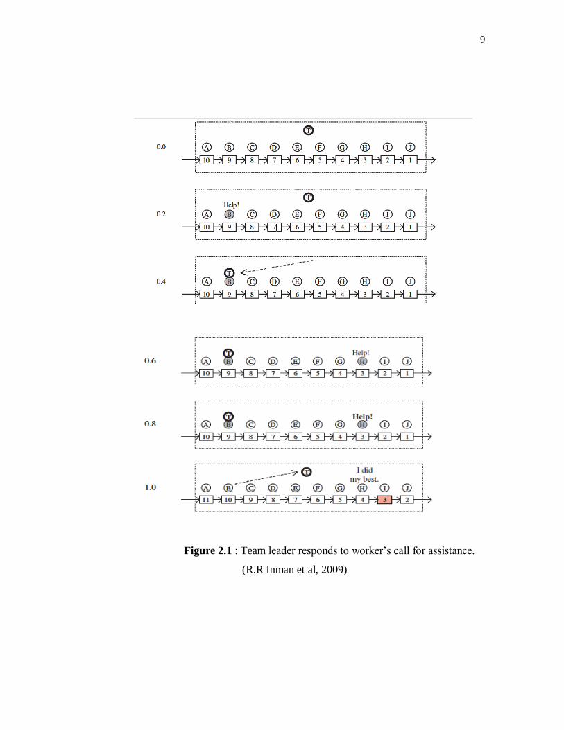
To clarify their work team model of a no-andon system, Figure 2.1 displays
an example section of the line in a series of six snapshots taken every 12 seconds.
(For simplicity, Figure 2.1 treats the line as an index line that holds the vehicles
stationary for one minute then instantaneously advances them all one station.)
Vehicles are shown as rectangles and workers as circles. The example 10-station
section has one worker per station (labelled A through J ) supported by one team
leader (labelled T). The following narrative accompanies Figure 2.1 (Robert R.
Inman et al, 2009).
7
8
9
Figure 2.1 : Team leader responds to worker’s call for assistance.
(R.R Inman et al, 2009)
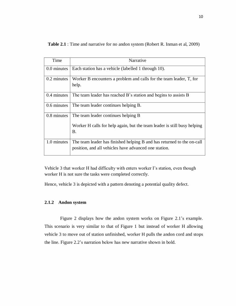
10
Table 2.1 : Time and narrative for no andon system (Robert R. Inman et al, 2009)
Time Narrative
0.0 minutes Each station has a vehicle (labelled 1 through 10).
0.2 minutes Worker B encounters a problem and calls for the team leader, T, for
help.
0.4 minutes The team leader has reached B’s station and begins to assists B
0.6 minutes The team leader continues helping B.
0.8 minutes The team leader continues helping B
Worker H calls for help again, but the team leader is still busy helping
B.
1.0 minutes The team leader has finished helping B and has returned to the on-call
position, and all vehicles have advanced one station.
Vehicle 3 that worker H had difficulty with enters worker I’s station, even though
worker H is not sure the tasks were completed correctly.
Hence, vehicle 3 is depicted with a pattern denoting a potential quality defect.
2.1.2 Andon system
Figure 2 displays how the andon system works on Figure 2.1’s example.
This scenario is very similar to that of Figure 1 but instead of worker H allowing
vehicle 3 to move out of station unfinished, worker H pulls the andon cord and stops
the line. Figure 2.2’s narration below has new narrative shown in bold.

11
Figure 2.2: Two workers needing help on a section with andon.
(R.R Inman et al, 2009)
12
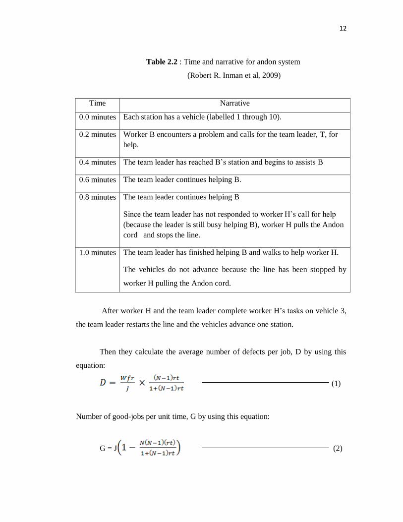
Table 2.2 : Time and narrative for andon system
(Robert R. Inman et al, 2009)
Time Narrative
0.0 minutes Each station has a vehicle (labelled 1 through 10).
0.2 minutes Worker B encounters a problem and calls for the team leader, T, for
help.
0.4 minutes The team leader has reached B’s station and begins to assists B
0.6 minutes The team leader continues helping B.
0.8 minutes The team leader continues helping B
Since the team leader has not responded to worker H’s call for help
(because the leader is still busy helping B), worker H pulls the Andon
cord and stops the line.
1.0 minutes The team leader has finished helping B and walks to help worker H.
The vehicles do not advance because the line has been stopped by
worker H pulling the Andon cord.
After worker H and the team leader complete worker H’s tasks on vehicle 3,
the team leader restarts the line and the vehicles advance one station.
Then they calculate the average number of defects per job, D by using this
equation:
(1)
Number of good-jobs per unit time, G by using this equation:
G = J (2)

13
Where:
f Fraction of unanswered calls that result in a defect.
D Average number of defects per job.
J Line rate (jobs per unit time).
W Total number of trained workers (¼number of work stations on the line).
T Number of teams on the line (W/N).
G Throughput of good jobs (good jobs per hour).
P Productivity (good jobs per hour per worker).
After doing some and calculation estimation based on the equation to the
good-job throughput in the No-Andon and Andon cases, respectively, as a function
of team size N, Figure 4 displays the results. As the team size gets larger, the team
leader must support more line workers and is less able to respond to calls for help.
Hence more defects creep in and the throughput of good jobs decreases.
Figure 2.3 : Throughput of defect-free jobs versus team size for Andon and Non-
Andon System (Blumenfeld and Inman, 2009)

14
As the result, in the Andon case, the line is stopped to prevent defects so the
total throughput is the same as the good-job throughput (because these models only
consider the defects resulting from calls for help that were not responded to). The
Andon system’s total throughput is less than the No-Andon’s, but the Andon’s
good-job throughput is much higher for larger team sizes.
2.2 THE CONCEPT OF ANDON SYSTEM
To design the Andon system, first the PIC16F88 microcontroller has been
decided as the connecting device between the machine and LED. The PIC16F88
microcontroller has been programmed with C Programming command installed in it.
2.3 LIGHT EMITTING DIODE (LED)
Light emitting diode ( LED) are the main component in the andon system. It
is commonly used on equipment in industrial manufacturing and process control
environments to provide visual indicators of a machine state or process event to
machine operators, technicians, production managers and factory personnel.
For this project, LED has been decided as the device of Andon lights. The
LED’s have three different colors which are red,yellow and green. Red is to indicate
that the machine is stop, yellow is to indicate that the machine is under maintenance
and green is to indicate the machine are being used.
This LEDs will be attach at the top of the machine as the visual warning
system to the users. The LEDs are programmed to light whenever the machine are
being used. When the user switch on the machine, the green light is on and it will
indicates that the machine is being used, so others users cannot used that machine.

15
While the green light is on but there is no activity (no push button) on the
machine for 10 seconds, the yellow light will on and it shows that the machine is
under maintenance or stop for a while.
When there is an emergency case happen to the machine, user will push the
STOP button and the red light will be on. This indicates that the machine is stop
because of breakdown.
2.4 PIC16F88 MICROCONTROLLER
A microcontroller is an electronic device that includes three components
Microprocessor, Memory and I/O on a single semiconductor unit called an Integrated
Circuit (Karthick Kumar Reddy et al. 2011). In addition to these components, the
microcontrollers include many supporting devices as shown in Figure 2.4. In this
paper, PIC16F88 is use and is available in 18-pin PDIP, SOIC and the features are
summarized in Table 2.3.
Figure 2.4 : PIC16F88 Microcontroller 18 Pin