Embed Size (px)
Citation preview

Design and Analysis of On-ChipCommunication for Network-on-Chip
Platforms
Zhonghai Lu
Stockholm 2007
Department of Electronic, Computer and Software SystemsSchool of Information and Communication Technology
Royal Institute of Technology (KTH)Sweden
Thesis submitted to the Royal Institute of Technology in partial fulfillmentof the requirements for the degree of Doctor of Technology

Lu, ZhonghaiDesign and Analysis of On-Chip Communication for Network-on-Chip Plat-
forms
ISBN 978-91-7178-580-0TRITA-ICT/ECS AVH 07:02ISSN 1653-6363ISRN KTH/ICT/ECS AVH-07/02 -SE
Copyright © Zhonghai Lu, March 2007
Royal Institute of TechnologySchool of Information and Communication TechnologyDepartment of Electronic, Computer and Software SystemsElectrum 229S-164 40 Kista, Sweden

Abstract
Due to the interplay between increasing chip capacity and complex applications,System-on-Chip (SoC) development is confronted by severe challenges, such asmanaging deep submicron effects, scaling communication architectures and bridg-ing the productivity gap. Network-on-Chip (NoC) has been a rapidly developedconcept in recent years to tackle the crisis with focus on network-based commu-nication. NoC problems spread in the whole SoC spectrum ranging from spec-ification, design, implementation to validation, from design methodology to toolsupport. In the thesis, we formulate and address problems in three key NoC areas,namely, on-chip network architectures, NoC network performance analysis, andNoC communication refinement.
Quality and cost are major constraints for micro-electronic products, particu-larly, in high-volume application domains. We have developed a number of tech-niques to facilitate the design of systems with low area, high and predictable per-formance. From flit admission and ejection perspective, we investigate the areaoptimization for a classical wormhole architecture. The proposals are simple buteffective. Not only offering unicast services, on-chip networks should also pro-vide effective support for multicast. We suggest a connection-oriented multicas-ting protocol which can dynamically establish multicast groups with quality-of-service awareness. Based on the concept of a logical network, we develop the-orems to guide the construction of contention-free virtual circuits, and employ aback-tracking algorithm to systematically search for feasible solutions.
Network performance analysis plays a central role in the design of NoC com-munication architectures. Within a layered NoC simulation framework, we developand integrate traffic generation methods in order to simulate network performanceand evaluate network architectures. Using these methods, traffic patterns may beadjusted with locality parameters and be configured per pair of tasks. We proposealso an algorithm-based analysis method to estimate whether a wormhole-switchednetwork can satisfy the timing constraints of real-time messages. This method isbuilt on traffic assumptions and based on a contention tree model that captures
iii

iv Abstract
direct and indirect network contentions and concurrent link usage.In addition to NoC platform design, application design targeting such a plat-
form is an open issue. Following the trends in SoC design, we use an abstractand formal specification as a starting point in our design flow. Based on the syn-chronous model of computation, we propose a top-down communication refine-ment approach. This approach decouples the tight global synchronization intoprocess local synchronization, and utilizes synchronizers to achieve process syn-chronization consistency during refinement. Meanwhile, protocol refinement canbe incorporated to satisfy design constraints such as reliability and throughput.
The thesis summarizes the major research results on the three topics.

Table of Contents
Acknowledgments vii
List of Publications ix
List of Figures xiv
Abbreviations xvi
1 Introduction 11.1 Network-on-Chip (NoC) . . . . . . . . . . . . . . . . . . . . . . 1
1.1.1 System-on-Chip (SoC) Design Challenges . . . . . . . . . 11.1.2 Network-on-Chip as a SoC Platform . . . . . . . . . . . . 41.1.3 On-Chip Communication Model . . . . . . . . . . . . . . 8
1.2 Research Overview . . . . . . . . . . . . . . . . . . . . . . . . . 101.3 Author’s Contributions . . . . . . . . . . . . . . . . . . . . . . . 11
2 NoC Network Architectures 172.1 Introduction . . . . . . . . . . . . . . . . . . . . . . . . . . . . . 17
2.1.1 On-Chip Communication Network . . . . . . . . . . . . . 172.1.2 Wormhole Switching . . . . . . . . . . . . . . . . . . . . 25
2.2 Flit Admission and Ejection . . . . . . . . . . . . . . . . . . . . 262.2.1 Problem Description . . . . . . . . . . . . . . . . . . . . 272.2.2 The Wormhole Switch Architecture . . . . . . . . . . . . 282.2.3 Flit Admission . . . . . . . . . . . . . . . . . . . . . . . 312.2.4 Flit Ejection . . . . . . . . . . . . . . . . . . . . . . . . . 33
2.3 Connection-oriented Multicasting . . . . . . . . . . . . . . . . . 362.3.1 Problem Description . . . . . . . . . . . . . . . . . . . . 362.3.2 The Multicasting Mechanism . . . . . . . . . . . . . . . 37
2.4 TDM Virtual-Circuit Configuration . . . . . . . . . . . . . . . . . 382.4.1 Problem Description . . . . . . . . . . . . . . . . . . . . 38
v

vi Table of Contents
2.4.2 Logical-Network-oriented VC Configuration . . . . . . . 392.5 Future Work . . . . . . . . . . . . . . . . . . . . . . . . . . . . . 43
3 NoC Network Performance Analysis 453.1 Introduction . . . . . . . . . . . . . . . . . . . . . . . . . . . . . 45
3.1.1 Performance Analysis for On-Chip Networks . . . . . . . 453.1.2 Practices of NoC Simulation . . . . . . . . . . . . . . . . 49
3.2 NNSE: Nostrum NoC Simulation Environment . . . . . . . . . . 503.2.1 Overview . . . . . . . . . . . . . . . . . . . . . . . . . . 503.2.2 The Simulation Kernel . . . . . . . . . . . . . . . . . . . 513.2.3 Network Configuration . . . . . . . . . . . . . . . . . . . 523.2.4 Traffic Configuration . . . . . . . . . . . . . . . . . . . . 533.2.5 An Evaluation Case Study . . . . . . . . . . . . . . . . . 56
3.3 Feasibility Analysis of On-Chip Messaging . . . . . . . . . . . . 573.3.1 Problem Description . . . . . . . . . . . . . . . . . . . . 573.3.2 The Network Contention Model . . . . . . . . . . . . . . 583.3.3 The Feasibility Test . . . . . . . . . . . . . . . . . . . . . 65
3.4 Future Work . . . . . . . . . . . . . . . . . . . . . . . . . . . . . 69
4 NoC Communication Refinement 714.1 Introduction . . . . . . . . . . . . . . . . . . . . . . . . . . . . . 71
4.1.1 Electronic System Level (ESL) Design . . . . . . . . . . 714.1.2 Communication Refinement . . . . . . . . . . . . . . . . 724.1.3 Synchronous Model of Computation (MoC) . . . . . . . . 73
4.2 The Communication Refinement Approach . . . . . . . . . . . . 764.2.1 Problem Description and Analysis . . . . . . . . . . . . . 764.2.2 Refinement Overview . . . . . . . . . . . . . . . . . . . 794.2.3 Channel Refinement . . . . . . . . . . . . . . . . . . . . 814.2.4 Process Refinement . . . . . . . . . . . . . . . . . . . . . 844.2.5 Communication Mapping . . . . . . . . . . . . . . . . . 90
4.3 Future Work . . . . . . . . . . . . . . . . . . . . . . . . . . . . . 91
5 Summary 935.1 Subject Summary . . . . . . . . . . . . . . . . . . . . . . . . . . 935.2 Future Directions . . . . . . . . . . . . . . . . . . . . . . . . . . 94
References 97
Appended papers 111

Acknowledgements
Studying towards Ph.D. takes five years, with 20% teaching workload. It is a longprocess filled with mixed feelings, pleasure and pressure, satisfaction and disap-pointment. The pleasure and enjoyment originate from the persistent developmentof innovative ideas in the frontline of the interesting research area. The pressuremay undergo in the face of frequent deadlines for tasks and papers, especially dur-ing the tight finance period in the department. The satisfaction comes often forthe recognition of a piece of innovative work while the disappointment may occurfor the sake of mis-understanding and rejections. My life as a Ph.D. student is acolorful picture, which composes a beautiful and important part of my life.
While this picture is painted, a lot of people have contributed in various ways.It is the right time and place to acknowledge their help. Professor Axel Jantschis the one I thank most. I thank him far more just because of the fact that he ismy supervisor. He is a very respectable person for his personality, knowledge andcreativity. I am lucky to be one of his students. In reality, he treats his studentsvery equally. He is not only a supervisor but also a colleague and a collaborator. Iam indebted to Dr. Ingo Sander. He has been acting as the co-supervisor for myPh.D. study, and helping me in all the ways possible. He is concerned with notonly my progress in research but also my office and health. We have had many andmany small talks and discussions, which are sources of friendship and inspiration.I thank Professor Shashi Kumar, who was my co-supervisor before he left KTH.
I acknowledge valuable discussions and diverse help from all my colleaguesin the System, Architecture and Methodology (SAM) group, particularly, the twoproject teams, Nostrum and ForSyDe, where I have been involved in. The Nostrumteam investigates network-on-chip architectures and associated design techniques.The present and past contributors include Mikael Millberg, Rikard Thid, ErlandNilsson, Raimo Haukilahti, Johnny Oberg, Kim Petersen and Per Badlund. Partic-ularly, I thank Rikard for his original work in the layered NoC simulation kernel.The ForSyDe team aims to develop a formal design methodology for System-on-Chip applications from modeling to implementation and verification. This team
vii

viii Acknowledgements
involves Ingo Sander, Tarvo Raudvere, Ashish Kumar Singh and Jun Zhu.I appreciate our system group, Hans Berggren and Peter Magnusson, for their
active and patient support in computer and network systems. I thank secretariesLena Beronius, Agneta Herling and Rose-Marie Lovenstig for their administrativeassistance in traveling and other issues.
I thank all other colleagues in the Department of Electronic, Computer andSoftware Systems for their various help and for the pleasant and encouraging en-vironment we contribute to and share. I thank Roshan Weerasekera for friendship.Special thanks should go to all my Chinese colleagues, particularly to Lirong, JianLiu, Li Li, Bingxin, and Jinliang, for the great occasions and happiness we share.
During my Ph.D. study period, I have supervised twelve Master theses. Theseworks have deepened my understanding on the corresponding subjects and most ofthem are excellent. I thank all the students for their hard and fruitful work, particu-larly, Bei Yin, Mingchen Zhong, Li Tong, Karl-Henrik Nielsen, Jonas Sicking andMing Liu.
I have taken an internship in Samsung Electronics in the summer of 2005.During the three-month period, I investigated the state-of-the-art interconnect tech-niques. I thank Mr. Soo Kwan Eo, Dr. Cheung and Dr. Yoo and all others in thesystem design technology group for their arrangements and assistance.
Finally I give my deepest gratitude to my family, my wife Yanhong and daugh-ter Lingyi. I could not count how many weekends I have spent with my computer,and how many times I have been late back home. Any piece of my achievementhas an invisible part of their contribution. I thank my brothers and sisters in Chinafor their endless concerns. I thank my parents for their permanent love and irre-placeable support.
The research presented in the dissertation is financed by the Swedish govern-ment within the SoCware program and the European Commission within the Sprintproject.
Zhonghai Lu
December 2006, Stockholm

List of Publications
Part A. Papers included in the thesis:
• NoC Network Architectures
1. Zhonghai Lu and Axel Jantsch. Flit admission in on-chip wormhole-switchednetworks with virtual channels. In Proceedings of the International Sympo-sium on System-on-Chip, pages 21-24, Tampere, Finland, November 2004.
2. Zhonghai Lu and Axel Jantsch. Flit ejection in on-chip wormhole-switchednetworks with virtual channels. In Proceedings of the IEEE NorChip Con-ference, pages 273-276, Oslo, Norway, November 2004.
3. Zhonghai Lu, Bei Yin, and Axel Jantsch. Connection-oriented multicasting inwormhole-switched networks on chip. In Proceedings of the IEEE ComputerSociety Annual Symposium on VLSI (ISVLSI’06), pages 205-210, Karlsruhe,Germany, March 2006.
4. Zhonghai Lu and Axel Jantsch. TDM virtual-circuit configuration in network-on-chip using logical networks. In submission to IEEE Transactions on VeryLarge Scale Integration Systems.
• NoC Network Performance Analysis
5. Zhonghai Lu and Axel Jantsch. Traffic configuration for evaluating networkson chip. In Proceedings of the 5th International Workshop on System-on-Chip for Real-time Applications, pages 535-540, Alberta, Canada, July 2005.
6. Zhonghai Lu, Mingchen Zhong, and Axel Jantsch. Evaluation of on-chip net-works using deflection routing. In Proceedings of the 16th ACM Great LakesSymposium on VLSI (GLSVLSI’06), pages 296-301, Philadelphia, USA, May2006.
ix

x List of Publications
7. Zhonghai Lu, Axel Jantsch and Ingo Sander. Feasibility analysis of messagesfor on-chip networks using wormhole routing. In Proceedings of the Asiaand South Pacific Design Automation Conference (ASPDAC’05), pages 960-964, Shanghai, China, January 2005.
• NoC Communication Refinement
8. Zhonghai Lu, Ingo Sander, and Axel Jantsch. Refining synchronous communi-cation onto network-on-chip best-effort services. In Alain Vachoux, editor,Applications of Specification and Design Languages for SoCs - Selected pa-pers from FDL 2005, Chapter 2, pages 23-38, Springer, 2006.
9. Zhonghai Lu, Ingo Sander, and Axel Jantsch. Towards performance-orientedpattern-based refinement of synchronous models onto NoC communication.In Proceedings of the 9th Euromicro Conference on Digital System Design(DSD’06), pages 37-44, Dubrovnik, Croatia, August 2006.
Part B. Publications not included in the thesis:
10. Zhonghai Lu, Ingo Sander, and Axel Jantsch. Refinement of a perfectlysynchronous communication model onto Nostrum NoC best-effort commu-nication service. In Proceedings of the Forum on Specification and DesignLanguages (FDL’05), Lausanne, Switzerland, September 2005.
11. Zhonghai Lu, Li Tong, Bei Yin, and Axel Jantsch. A power-efficient flit-admission scheme for wormhole-switched networks on chip. In Proceedingsof the 9th World Multi-Conference on Systemics, Cybernetics and Informat-ics, Florida, U.S.A., July 2005.
12. Zhonghai Lu, Rikard Thid, Mikael Millberg, Erland Nilsson, and Axel Jantsch.NNSE: Nostrum network-on-chip simulation environment. In Proceedingsof Swedish System-on-Chip Conference, Stockholm, Sweden, April 2005.
13. Zhonghai Lu, Rikard Thid, Mikael Millberg, Erland Nilsson, and Axel Jantsch.NNSE: Nostrum network-on-chip simulation environment. In The Univer-sity Booth Tool-Demonstration Program of the Design Automation and Testin Europe Conference, Munich, Germany, March 2005.
14. Ingo Sander, Axel Jantsch, and Zhonghai Lu. Development and application ofdesign transformations in ForSyDe. IEE Proceedings - Computers & DigitalTechniques, 150(5):313-320, September 2003.

List of Publications xi
15. Zhonghai Lu and Axel Jantsch. Network-on-chip assembler language (ver-sion 0.1). Technical Report TRITA-IMIT-LECS R 03:02, ISSN 1651-4661,ISRN KTH/IMIT/LECS/R-03/02-SE, Royal Institute of Technology, Stock-holm, Sweden, June 2003.
16. Ingo Sander, Axel Jantsch, and Zhonghai Lu. Development and application ofdesign transformations in ForSyDe. In Proceedings of Design, Automationand Test in Europe Conference, pages 364-369, Munich, Germany, March2003.
17. Zhonghai Lu and Raimo Haukilahti. NoC application programming inter-faces. In Axel Jantsch and Hannu Tenhunen, editors, Networks on Chip,Chapter 12, pages 239-260. Kluwer Academic Publishers, February 2003.
18. Zhonghai Lu, Ingo Sander, and Axel Jantsch. A case study of hardware andsoftware synthesis in ForSyDe. In Proceedings of the 15th InternationalSymposium on System Synthesis (ISSS’02), pages 86-91, Kyoto, Japan, Oc-tober 2002.
19. Zhonghai Lu and Axel Jantsch. Admitting and Ejecting Flits in Wormhole-switched On-chip Networks. In submission to Journal of Systems Architec-tures (under the second round review).

xii

List of Figures
1.1 A mesh NoC with 9 nodes . . . . . . . . . . . . . . . . . . . . . 51.2 On-chip communication layers with Application Level Interface
(ALI) and Core Level Interface (CLI) . . . . . . . . . . . . . . . 9
2.1 Flits delivered in a pipeline . . . . . . . . . . . . . . . . . . . . . 252.2 Virtual channels (lanes) . . . . . . . . . . . . . . . . . . . . . . . 262.3 Flit admission and ejection . . . . . . . . . . . . . . . . . . . . . 272.4 Flitization and assembly . . . . . . . . . . . . . . . . . . . . . . 272.5 A canonical wormhole lane switch (ejection not shown) . . . . . . 292.6 Lane-to-lane associations . . . . . . . . . . . . . . . . . . . . . . 302.7 Organization of packet- and flit-admission queues . . . . . . . . . 312.8 The coupled admission sharing a (p+1)-by-p crossbar . . . . . . . 332.9 The ideal sink model . . . . . . . . . . . . . . . . . . . . . . . . 342.10 The p-sink model . . . . . . . . . . . . . . . . . . . . . . . . . . 352.11 The virtual-circuit configuration problem . . . . . . . . . . . . . 392.12 TDM virtual circuits . . . . . . . . . . . . . . . . . . . . . . . . 402.13 Using logical networks to avoid conflict . . . . . . . . . . . . . . 412.14 The view of logical networks . . . . . . . . . . . . . . . . . . . . 412.15 Virtual-circuit configuration approaches . . . . . . . . . . . . . . 44
3.1 Network evaluation . . . . . . . . . . . . . . . . . . . . . . . . . 513.2 The communication layers in Semla . . . . . . . . . . . . . . . . 513.3 Network configuration tree . . . . . . . . . . . . . . . . . . . . . 533.4 The traffic configuration tree . . . . . . . . . . . . . . . . . . . . 543.5 Feasibility analysis in a NoC design flow . . . . . . . . . . . . . . 573.6 Network contention and contention tree . . . . . . . . . . . . . . 603.7 Message contention for links simultaneously . . . . . . . . . . . 623.8 Avoided flit-delivery scenario . . . . . . . . . . . . . . . . . . . 633.9 Message scheduling . . . . . . . . . . . . . . . . . . . . . . . . . 64
xiii

xiv List of Figures
3.10 A three-node contention tree . . . . . . . . . . . . . . . . . . . . 653.11 Message scheduling and contended slots . . . . . . . . . . . . . . 663.12 A feasibility analysis flow . . . . . . . . . . . . . . . . . . . . . . 68
4.1 Computation and communication elements . . . . . . . . . . . . . 774.2 NoC communication refinement . . . . . . . . . . . . . . . . . . 804.3 Processes for synchronization . . . . . . . . . . . . . . . . . . . . 864.4 Wrap a strong process . . . . . . . . . . . . . . . . . . . . . . . . 874.5 Wrap a strict process . . . . . . . . . . . . . . . . . . . . . . . . 874.6 A strong and a strict process . . . . . . . . . . . . . . . . . . . . 874.7 Two non-strict processes . . . . . . . . . . . . . . . . . . . . . . 874.8 Feedback loop . . . . . . . . . . . . . . . . . . . . . . . . . . . . 894.9 A relax-synchronization process . . . . . . . . . . . . . . . . . . 89

Abbreviations
ASIC Application-Specific Integrated CircuitAXI Advanced eXtensible InterfaceALI Application-Level InterfaceCAD Computer Aided DesignCLI Core-Level InterfaceCMOS Complementary Metal Oxide SemiconductorCT Contention TreeDSM Deep SubMicronDTL Device Transaction LevelESL Electronic System LevelFIFO First In First OutForSyDe FORmal SYstem DEsignFPGA Field-Programmable Gate ArrayGUI Graphical User InterfaceITRS International Technology Roadmap for SemiconductorsIP Intellectual PropertyLN Logical NetworkMoC Model of ComputationNNSE Nostrum Network-on-Chip Simulation EnvironmentNoC Network on ChipOCP Open Core ProtocolPC Physical ChannelPE Processing ElementQoS Quality of ServiceRNI Resource Network InterfaceRT Real TimeRTL Register Transfer LevelSEMLA Simulation EnvironMent for Layered ArchitectureSoC System on ChipTDM Time-Division MultiplexingULSI Ultra Large Scale IntegrationVC Virtual Channel / Virtual CircuitVCI Virtual Component Interface
xv

xvi Abbreviations

Chapter 1
Introduction
This chapter highlights System-on-Chip design challenges and introduces the Network-on-Chip concept. We also give an overview of the research presented in the thesisand outline the author’s contributions to the enclosed papers.
1.1 Network-on-Chip (NoC)
1.1.1 System-on-Chip (SoC) Design Challenges
Our life has been largely shaped by the exciting developments of modern elec-tronic technologies, such as pervasive and ubiquitous computing, ambient intelli-gence, communication, and Internet. Today micro-electronic products are influenc-ing the ways of communication, learning and entertainment. The key driving forcefor the developments during decades is the System-on-Chip (SoC) technologies,where complex applications are integrated onto single ULSI chips. Not only func-tionally enriched, these products such as mobile phones, notebooks and personalhandheld sets are becoming faster, smaller-in-size, larger-in-capacity, lighter-in-weight, lower-in-power-consumption and cheaper. One could favorably think thatthis trend will persistently continue. Following this trend, we could integrate moreand more complex applications and even systems onto a single chip. However, ourcurrent methodologies for SoC design and integration do not evenly advance dueto the big challenges confronted.
• Deep SubMicron (DSM) effects [43, 80, 134]: In early days of VLSI design,signal integrity effects such as interconnect delay, crosstalk, inter-symbol in-terference, substrate coupling, transmission-line effects, etc. were negligible
1
2 Chapter 1. Introduction
due to relatively slow clock speed and low integration density. Chip inter-connect was reliable and robust. At the scale of 250 nm with aluminum and180 nm with copper and below, interconnect started to become a dominatingfactor for chip performance and robustness. As the transistor density is in-creased, wires are getting neither fast nor reliable [43]. More noise sourcesdue to inductive fringing, crosstalk and transmission line effects are cou-pled to other circuit nodes globally on the chip via the substrate, commonreturn ground and electromagnetic interference. More and more aggressiveuse of high-speed circuit families, for example, domino circuitry, scalingof power supply and threshold voltages, and mixed-signal integration com-bine to make the chips more noise-sensitive. Third, higher device densitiesand faster switching frequencies cause larger switching-currents to flow inthe power and ground networks. Consequently, power supply is plaguedwith excessive IR voltage drops as wells as inductive voltage drops over thepower distribution network and package pins. Power supply noise degradesnot only the driving capability of gates but also causes possible false switch-ing of logical gates. Today signal and power integrity analysis is as importantas timing, area and power analysis.
• Global synchrony [3, 47]: Predominating digital IC designs have been fol-lowing a globally synchronous design style where a global clock tree is dis-tributed on the chip, and logic blocks function synchronously. However,this style is unlikely to survive with future wire interconnect. The reasonis that technology scaling does not treat wire delay and gate delay equally.While gate delay (transistor switching time) has been getting dramaticallysmaller in proportion to the gate length, wires have slowed down. As the chipbecomes communication-bound at 130 nm, multiple cycles are required totransmit a signal across its diameter. As estimated in [3], with the processtechnology of 35 nm in year 2014, the latency across the chip in a top-levelmetal wire will be 12 to 32 cycles depending on the clock rate assuming besttransmission conditions such as very low-permittivity dielectrics, resistivityof pure copper, high aspect ratio (ratio of wire height to wire width) wiresand optimally placed repeaters. Moreover, a clock tree is consuming largerportions of power and area budget and clock skew is claiming an ever largerportion of the total cycle time [94]. Even if we have an unlimited numberof transistors on a chip, chip design is to be constrained by communicationrather than capacity. A future chip is likely to be partitioned into locallysynchronous regions but global communication is asynchronous, so calledGALS (Globally Asynchronous Locally Synchronous).

1.1. Network-on-Chip (NoC) 3
• Communication architecture [9, 19]: Most current SoCs have a bus-basedarchitecture, such as simple, hierarchical or crossbar-type buses. In contrastto the scaling of chip capacity, buses do not scale well with the system sizein terms of bandwidth, clocking frequency and power. First, a bus systemhas very limited concurrent communication capability since only one de-vice can drive a bus segment at a time. Current SoCs integrate fewer thanfive processors and, rarely, more than 10 bus masters. Second, as the num-ber of clients grows, the intrinsic resistance and capacitance of the bus alsoincrease. This means that the bus speed is inherently difficult to scale up.Third, a bus is inefficient in energy since every data transfer is broadcast. Theentire bus wire has to be switched on and off. This means that the data mustreach each receiver at great energy cost. Although improvements such assplit-transaction protocols and advanced arbitration schemes for buses havebeen proposed, these incremental techniques can not overcome the funda-mental problems. To explore the future chip capacity, for high-throughputand low-power applications, hundreds of processor-sized resources must beintegrated. A bus-based architecture would become a critical performanceand power bottleneck due to the scalability problem. Novel on-chip commu-nication architectures are desired.
• Power and thermal management [85, 105]: As circuits run with higher andhigher frequencies, lowering power consumption is becoming extremely im-portant. Power is a design constraint, which is no more subordinate to per-formance. Despite process and circuit improvements, power consumptionshows rapid growth. Equally alarming is the growth in power density on thechip die, which increases linearly. In face of DSM effects, reducing powerconsumption is becoming even more challenging. As devices shrink to sub-micron dimensions, the supply voltage must be reduced to avoid damagingelectric fields. This development, in turn, requires a reduced threshold volt-age. However, leakage current increases exponentially with a decrease inthe threshold voltage. In fact, a 10% to 15% reduction can cause a two-foldincrease in leakage current. In increasingly smaller devices, leakage will be-come the dominant source of power consumption. Further, leakage occurs aslong as power flows through the circuit. This constant current can producean increase in the chip temperature, which in turn causes an increase in thethermal voltage, leading to a further increase in leakage current.
• Verification [107, 111]: Today SoC design teams are struggling with thecomplexity of multimillion gate designs. System verification runs through

4 Chapter 1. Introduction
the whole design process from specification to implementation, typicallywith formal methods or simulation-based validation. As the system hasbecome extremely complex, the verification or validation consumes an in-creasing portion of the product development time. The verification efforthas reached as high as 70% of engineering efforts.
• Productivity gap [4, 111]: Simply put, productivity gap is the gap betweenwhat we are capable of building and what we are capable of designing. Inline with Moore’s law [83], the logic capacity of a single chip has increasedat the rate of 58% per annum compounded. Soon the complexity of the chipenters the billion-transistor era. The complexity of developing SoCs is in-creasing continuously in order to exploit the potential of the chip capacity.However, the productivity of hardware and software design is not growingat a comparable pace. The hardware design productivity is increased at arate in the range 20% to 25% per annum compounded. Even worse, the soft-ware design productivity improves at a rate in the range from 8% to 10% perannum compounded. As a consequence, the costs of developing advancedSoCs are increasing at an alarming pace and time-to-market is negatively af-fected. The design team size is increased by more than 20% per year. Thishuge investment is becoming a serious threshold for new product develop-ments and is slowing down the innovation in the semiconductor industry.As stated in the ITRS roadmap [4], cost of design is the greatest threat tocontinuation of the semiconductor roadmap.
1.1.2 Network-on-Chip as a SoC Platform
Innovations occur where challenges are present. Network-on-Chip (NoC) was pro-posed in face of those challenges in around year 2001 in the SoC community[9, 27, 37, 41, 109, 119]. In March 2000, packet-switched networks were proposedin SPIN [37] as a global and scalable SoC interconnection. The term Network-on-Chip appeared initially in November 2000 [41] where NoC was proposed asa platform to cope with the productivity gap. In June 2001, Dally and Towlesproposed NoC as a structured way of communication to connect IP modules [27].The GigaScale Research Center (GSRC) suggested NoC to address interconnec-tion woes [119]. In October 2001, researchers from the Philips Research presenteda router architecture supporting both best-effort and guaranteed-throughput trafficfor Network-on-Silicon [109]. In January 2002, Luca and De Micheli formulatedNoC as a new SoC paradigm [9]. While network-on-chip is still in its infancy, the

1.1. Network-on-Chip (NoC) 5
S
S
S
Resource
RNI
Resource
RNI
Resource
RNI
S
S
Resource
RNI
Resource
RNI
S
S
S
Resource
RNI
Resource
RNI
S
Resource
RNI
Resource
RNI
SwitchLink (Physical channel)
Figure 1.1. A mesh NoC with 9 nodes
concept has spread and been accepted in academia very rapidly. Some big com-panies, for instance, NXP semiconductors (former part of Philips Semiconductors)and ST Micro-electronics, are also very active in this field [34, 52]. A comprehen-sive survey on current research and practices of NoC can be found in [13].
Aimed to be a systematic approach, NoC proposes networks as a scalable,reusable and global communication architecture to address the SoC design chal-lenges. As an instance, Nostrum [81, 90] is the name of the Network-on-Chipconcept developed at the Royal Institute of Technology (KTH), Sweden. It fea-tures a mesh structure composed of switches with each resource connected to ex-actly one switch, as shown in Figure 1.1. A resource can be a processor, memory,ASIC, FPGA, IP block or a bus-based subsystem. The resources are placed on theslots formed by the switches. The maximal resource area is defined by the max-imal synchronous region of a technology. The resources perform their own com-putational, storage and/or I/O processing functionalities, and are equipped withResource-Network-Interfaces (RNIs) to communicate with each other by routingpackets instead of driving dedicated wires.
Communication network is a well-known concept developed in the context oftelephony, computer communication as well as parallel machines. On-chip net-works share many characteristics with these networks, but also have significantdifferences. For clear presentation, throughout the thesis, we also call an on-chip

6 Chapter 1. Introduction
network a micro-network, a parallel-machine network a macro-network, a tele-phony or computer network a tele-network. On-chip networks are developed on asingle chip and designed for closed systems targeting perhaps heterogeneous ap-plications. Parallel-machine networks are developed on distributed boards and de-signed for a particular application which typically executes specific algorithms.Computer networks are geographically distributed and designed for open systemsrunning diverse applications from client-server, peer-to-peer and multicast appli-cations. Telephony networks are also geographically distributed but are designedmainly for the purposes of communicating voice, video and data. The design of aclosed system allows for customization in which the network properties includingthe network-level, link-level and physical-level properties can be propagated to theapplication level and both communication and computation may be efficiently op-timized. Since a micro-network is built on a single chip, it can have wide parallelwires and allows high rate synchronous clocking. On the other hand, it has morestringent constraints in performance, area and power, which are typical trade-offconsiderations for SoC designs. As communication is to transfer data, timing isthe first-level citizen. On-chip networks have the strictest requirement on delayand jitter. The time scale is measured in nano seconds. This requirement precludesmany of the software-based sophisticated arbitration, routing and flow-control al-gorithms. Cost is a major concern for on-chip networks since most SoCs targethigh-volume markets. The buffering in an on-chip network has very limited spaceand is expensive in comparison with board-level, local-area and wide-area net-works. This means that a NoC allows a limited count of routing tables and virtual-channel buffers in network nodes. Power consumption is important for all kinds ofnetworks. However, on-chip networks are developed also for embedded applica-tions with battery-driven devices. Such applications require extremely low powerwhich is not comparable to large-scale networks. As we also mentioned, on-chipnetwork designs are confronted by the DSM effects. Taming bad physical effects isas important as network design itself. Furthermore, many SoC networks are devel-oped as a platform for multiple use cases, not only for a single use case. Thereforedesigning micro-networks also need to take reconfigurability into account.
As we view it, Network-on-Chip is a revolutionary rather than evolutionaryapproach to address the SoC design crisis. It shifts our focus from computation tocommunication. It should take interconnect into early consideration in the designprocess, and might favor a meet-in-the middle (platform-based) design methodol-ogy against a top-down or bottom-up approach. NoC has the following features:
• Interconnect-aware [93]: As the technology scales, the reachable region inone clock cycle diminishes [3]. Consequently, chip design is increasingly

1.1. Network-on-Chip (NoC) 7
becoming communication-bound rather than capacity-bound. Since the sizeof a single module is limited by the reachable region in one cycle, to exploitthe huge chip capacity, the entire chip has to be partitioned into multipleregions. A good partitioning should be regular, making it easier to man-age the properties of long wires including middle-layer and top-layer wires.Each module is situated in one partitioned region and maintains its own syn-chronous region. In this way, the reliance on global synchrony and use ofglobal wires can be alleviated. To guarantee correct operation, registers maybe used in wire segments to make the design latency-insensitive [17]. Be-sides, each IP may be attached to a switch. Switches are in turn connectedwith each other to route packets in the network. The signal and power in-tegrity issues may be addressed at the physical, link and higher layers. Forexample, redundancy in time, space and information can be incorporated intransmission to achieve reliability. By physically structuring the communi-cation and successfully suppressing the DSM effects, the design robustnessand reliability can be improved.
• Communication-centric [10]: Networking distributed IP modules in a parti-tioned chip results in a naturally parallel communication infrastructure. Aslong as the chip capacity is not exceeded, the number of cores which can beintegrated on a single chip is scalable. The inter-core communications sharethe total network bandwidth with a high degree of concurrency. The networkcan be dimensioned to suit the bandwidth need of the application under in-terest. The parallel architecture allows concurrent processing in computationand communication. This helps to leverage performance and reduce powerin comparison with a sequential architecture permitting only sequentializedprocessing. A protocol stack is typically built to abstract the network-basedcommunication. Each layer has well-defined functionalities, protocols andinterfaces. The design space at each layer has to be sufficiently explored. Thetradeoffs between performance and cost should be considered in the design,analysis and implementation of the communication architecture. Quality-of-Service (QoS) and system-wide performance analysis are central issues toaddress predictability.
• Platform-based [50, 87]: Since the cost of design is the major obstacle forinnovative and complex SoCs [46], developing a programmable, reconfig-urable and extensible communication platform is essential for SoC designs.To this end, NoC shall serve as a communication and integration platform

8 Chapter 1. Introduction
providing a hardware communication architecture, an associated intercon-nect interface, as well as a high-level interface for integrating hardware IPs,custom logic and for software programming. This enables the architecture-level reuse. One challenge is to address the balance between generality andoptimality. A platform must serve not only one application but also many ap-plications within an application domain. On the other hand, customizationto enhance performance and efficiency is needed to make designs competi-tive. Providing well-defined interfaces at least at the network level and theapplication level is important, because it enables IPs and functional blocksto be reusable. Interface standardization is one major concern to make IPsfrom different vendors exchangeable. It must be efficient and also addresseslegacy IPs. The concept of interface-based design has been shown successfulfor IP plug-and-play in the history of software and hardware developments,for example, instruction sets and various interconnect buses or protocols suchas Peripheral Component Interface (PCI) and Universal Serial Bus (USB). ANoC design methodology should also favor communication interfaces forthe greatest possible IP reuse and integration [112, 129]. Using validatedcomponents and architectures in a design flow shrinks verification effort, re-duces time-to-market and guarantees product quality, thus enhancing designproductivity.
As such, NoC research does not deal with only several aspects of SoC de-sign but creates a new area [50]. The term NoC is used today mostly in a verybroad meaning. It encompasses the hardware communication infra-structure, themiddleware and operating system, application programming interfaces [64, 101],the design methodology and its associated tool chain. The challenges for NoC re-search have thus been distributed in all aspects of SoC design from architecture toperformance analysis, from traffic characterization to application design.
1.1.3 On-Chip Communication Model
On-chip communication is to provide a means to enable interprocess communica-tion with a set of constraints and properties satisfied. A good view of network-based process-to-process communication is to follow the ISO’s OSI model [135].The seven-layer model was proposed to interconnect open systems, which are het-erogeneous and distributed. The layered structure decomposes the communicationproblem into more manageable components at different hierarchical layers. Ratherthan a monolithic structure, several layers are designed, each of which solves onepart of the problem. Besides, layering provides a more modular design. At each

1.1. Network-on-Chip (NoC) 9
oN
C
P
TAL
FORM
OS & Middleware
Switch Switch Switch
Comm. AdapterSession
Transport
CLI
ALI
message/transaction
packet/stream
NetworkLinkPhyscial
phit/flit
Software coreOSI layer Hardware core
Presentation
Application P1 P2 P3 P4
Figure 1.2. On-chip communication layers with Application Level Interface (ALI)and Core Level Interface (CLI)
layer, protocols and services, which are implementation-independent, are well-defined. Peer entities at the same layer can thus communicate with each othertransparently. Adding new services to one layer may only need to modify the func-tionality at one layer, reusing the functions provided at all the other layers. Due tothese advantages, several NoC groups [9, 82, 119] have followed this model andadapted it to build a protocol stack for on-chip communication.
As a platform, NoC shall provide well-defined interfaces for application pro-gramming and IP integration. Two levels of interfaces can be identified. One is theCore-Level Interface (CLI), which is used to connect hardware cores. At this level,IPs and processors implement interfaces such as AXI [6], OCP [95], VCI [130],CoreConnect [45] and DTL [104]. The other level interface is for integrating hard-ware logic via a communication adapter and for programming embedded software.The Operating System (OS) [92] and middleware can be part of the platform. Thislevel of interface is Application-Level Interface (ALI). A recent proposal of thetwo-level interfaces for multiprocessors on chip can be found in [129].
An on-chip communication model combines the two views: abstract layeredcommunication and interface-based communication. Although having been dis-cussed separately, the two views are coherent, as shown in Figure 1.2. As canbe seen, hardware and software processes (illustrated as P1, P2, P3, P4 in Figure1.2) representing the application layer use the ALI. The hardware communicationadapter for integrating hardware cores and operating system & middleware for in-tegrating software cores realize the session and transport layers, and connect to theCLI. The CLI encapsulates the network. It is worth noting that bypassing one layeris possible, as long as the interfaces match. For example, if a hardware IP imple-

10 Chapter 1. Introduction
ments the CLI, it can be directly connected to the CLI instead of connecting to theALI, bypassing the communication adapter.
1.2 Research Overview
We have been orienting our NoC research towards three key issues: on-chip net-work architectures, network performance analysis and application design method-ology. The network communication architectures deal with the design of on-chipnetworks. The performance analysis evaluates the network performance and helpsto uncover the impact of network parameters on performance. The design method-ology is concerned with how to design applications on a NoC platform. Specifi-cally, we deal with communication refinement that synthesizes the communicationin a system model into on-chip communication. Essentially these topics deal withthe design and analysis of on-chip communication for NoC platforms.
We have identified and formulated problems related to the three aspects men-tioned above. The thesis is based on the research results from these studies. In thefollowing, we give a brief sketch of the main results:
• NoC network architectures: We have proposed cost-effective switch archi-tectures, a connection-oriented multicasting scheme, as well as a TDM (TimeDivision Multiplexing) virtual-circuit configuration method using logical net-works. After studying wormhole switch micro-architectures, we proposeflit admission and ejection schemes, which are cost-effective with mini-mal performance penalty. Our multicasting mechanism is also proposed forwormhole-switched networks. It is connection-oriented, and a connectioncan be established dynamically. Based on the concept of a logical network,we have developed theorems and used a back-tracking algorithm to configurecontention-free TDM virtual-circuits.
• NoC network performance analysis: We have investigated traffic configu-ration, carried out network simulation and made feasibility analysis. Wepropose how to configure synthetic traffic patterns using distribution withcontrollable locality or channel-by-channel customization. This traffic con-figuration method has been integrated into our Nostrum NoC Simulation En-vironment (NNSE). A case study on the deflection networks shows that oursimulator enables to explore the architectural design space and helps to makeproper decisions on topology, routing schemes and deflection policies. Thefeasibility analysis aids designers with information about whether the appli-cation can fulfill the timing requirements of messages on the network and
1.3. Author’s Contributions 11
how efficient network resources can be utilized. It allows one to evaluate thenetwork using algorithm instead of simulation. Hence, it is more efficient butless accurate. This feasibility analysis is performed on wormhole-switchednetworks.
• NoC communication refinement: Based on a synchronous system model, wehave proposed a communication refinement approach that refines the ab-stract communication into network-based communication. During the re-finement, synchronization consistency is maintained in order to be correct-by-construction and protocol refinement can be incorporated to satisfy per-formance constraints.
Next, we summarize the author’s contributions in each of the enclosed papers.
1.3 Author’s Contributions
The thesis is based on a collection of papers, which are all peer-reviewed exceptPaper 4 that is under review. The papers are grouped into three blocks, namely,NoC network architectures, NoC network performance analysis, and NoC commu-nication refinement. Each block is dedicated to one chapter in the thesis and weconcentrate on introducing the author’s contributions in each chapter. The detailedmaterials, experiments, results and other related work are referred to the papers. Inthe following, we summarize the enclosed papers highlighting the author’s contri-butions. These papers are also listed in the references.
• NoC Network Architectures
Paper 1 [66]. Zhonghai Lu and Axel Jantsch. Flit admission in on-chipwormhole-switched networks with virtual channels. In Proceedings ofthe International Symposium on System-on-Chip, pages 21-24, Tam-pere, Finland, November 2004.This paper discusses the flit admission problem in input-buffering andoutput-buffering wormhole switches. Particularly it presents a novelcost-effective coupling scheme that binds flit admission queues withoutput physical channels in a one-to-one correspondence manner. Theexperiments suggest that the network performance is equivalent to thebase line scheme which connects a flit admission queue to all the outputphysical channels.Author’s contributions: The author contributed with the problem for-mulation, conducted experiments and wrote the manuscript.

12 Chapter 1. Introduction
Paper 2 [67]. Zhonghai Lu and Axel Jantsch. Flit ejection in on-chipwormhole-switched networks with virtual channels. In Proceedings ofthe IEEE NorChip Conference, pages 273-276, Oslo, Norway, Novem-ber 2004.This paper studies flit ejection models in a wormhole virtual channelswitch. Instead of the costly ideal flit-ejection model, two alternativeswhich largely reduce the buffering cost are proposed. Experimentsshow that the p-sink model achieves nearly equivalent performancewith the ideal sink model if the network is not overloaded.Author’s contributions: The author formulated the flit-ejection prob-lem, proposed solutions, conducted experiments and wrote the manu-script.
Paper 3 [75]. Zhonghai Lu, Bei Yin, and Axel Jantsch. Connection-oriented multicasting in wormhole-switched networks on chip. In Pro-ceedings of the IEEE Computer Society Annual Symposium on VLSI(ISVLSI’06), pages 205-210, Karlsruhe, Germany, March 2006.This paper presents a connection-oriented multicast scheme in wormhole-switched NoCs. In this scheme, a multicast procedure consists of es-tablishment, communication and release phases. A multicast group canrequest to reserve virtual channels during establishment and has prior-ity on arbitration of link bandwidth. This multicasting method has beeneffectively implemented in a mesh network with deadlock freedom.Our experiments show that the multicast technique improves through-put, and does not exhibit significant impact on unicast performance ina network with mixed unicast and multicast traffic.Author’s contributions: The author contributed with the idea and pro-tocol design, suggested experimentation methods, and wrote the ma-nuscript. The implementation and experiments were conducted by BeiYin.
Paper 4 [65]. Zhonghai Lu and Axel Jantsch. TDM virtual-circuit con-figuration in network-on-chip using logical networks. In submission toIEEE Transactions on Very Large Scale Integration Systems.Configuring Time-Division-Multiplexing (TDM) Virtual Circuits (VCs)on network-on-chip must guarantee conflict freedom for VCs besidesallocating sufficient time slots to them. Using the generalized conceptof logical networks, we develop and prove theorems that constitute suf-ficient and necessary conditions to establish conflict-free VCs. More-over, we give a formulation of the multi-node VC configuration prob-

1.3. Author’s Contributions 13
lem and suggest a back-tracking algorithm to find solutions by con-structively searching the solution space.
Author’s contributions: The author developed and proved the theorems,formulated the problem, wrote the program, conducted experimentsand wrote the manuscript.
• NoC Network Performance Analysis
Paper 5 [68]. Zhonghai Lu and Axel Jantsch. Traffic configuration forevaluating networks on chip. In Proceedings of the 5th InternationalWorkshop on System-on-Chip for Real-time Applications, pages 535-540, Alberta, Canada, July 2005.
This paper details the traffic configuration methods developed for NNSE.It presents a unified expression to configure both uniform and localitytraffic and proposes application-oriented traffic configuration for on-chip network evaluation.
Author’s contributions: The author formulated the unified expressionfor the regular traffic patterns and defined application-oriented traffic,integrated the methods in NNSE, conducted experiments and wrote themanuscript.
Paper 6 [76]. Zhonghai Lu, Mingchen Zhong, and Axel Jantsch. Evalu-ation of on-chip networks using deflection routing. In Proceedings ofthe 16th ACM Great Lakes Symposium on VLSI (GLSVLSI’06), pages296-301, Philadelphia, USA, May 2006.
This paper evaluates the performance of deflection networks with dif-ferent topologies such as mesh, torus and Manhattan Street Network,different routing algorithms such as random, dimension XY, delta XYand minimum deflection, as well as different deflection policies suchas non-priority, weighted priority and straight-through policies. Theresults suggest that the performance of a deflection network is moresensitive to its topology than the other two parameters. It is less sensi-tive to its routing algorithm, but a routing algorithm should be minimal.A priority-based deflection policy that only uses global and history-related criterion can achieve both better average-case and worst-caseperformance than a non-priority or priority policy that uses local andstateless criterion. These findings may be used as guidelines by design-ers to make right decisions on the deflection network architecture.

14 Chapter 1. Introduction
Author’s contributions: The author formulated the problem, proposedsolution schemes, and wrote the manuscript. The implementation andexperiments were conducted by Mingchen Zhong.
Paper 7 [69]. Zhonghai Lu, Axel Jantsch and Ingo Sander. Feasibilityanalysis of messages for on-chip networks using wormhole routing. InProceedings of the Asia and South Pacific Design Automation Confer-ence, pages 960-964, Shanghai, China, January 2005.
The paper proposes a method for investigating the feasibility of deliver-ing mixed real-time and nonreal-time messages in wormhole-switchednetworks. Particularly it describes a contention tree model for the esti-mation of worst-case performance for delivering real-time messages.
Author’s contributions: The author formulated the contention tree model,developed the algorithm, wrote the program, performed experiments,and wrote the manuscript.
• NoC Communication Refinement
Paper 8 [71]. Zhonghai Lu, Ingo Sander, and Axel Jantsch. Refining syn-chronous communication onto network-on-chip best-effort services. InAlain Vachoux, editor, Applications of Specification and Design Lan-guages for SoCs - Selected papers from FDL 2005. Springer, Chapter2, pages 23-38, 2006.
The paper proposes a top-down design flow to refine synchronous com-munication onto NoC best-effort services. It consists of three steps,namely, channel refinement, process refinement, and communicationmapping. In channel refinement, synchronous channels are replacedwith stochastic channels abstracting the best-effort service. In processrefinement, processes are refined in terms of interfaces and synchro-nization properties. Particularly, we use synchronizers to maintain localsynchronization of processes and thus achieve synchronization consis-tency, which is a key requirement while mapping a synchronous modelonto an asynchronous architecture. Within communication mapping,the refined processes and channels are mapped onto a NoC platform.A digital equalizer is used as a tutorial example and implemented inthe Nostrum NoC platform to illustrate the feasibility of our concepts.
Author’s contributions: The author proposed the design flow for thecommunication refinement, developed solutions for the synchroniza-tion problem, conducted the case study, and wrote the manuscript.

1.3. Author’s Contributions 15
Paper 9 [72]. Zhonghai Lu, Ingo Sander, and Axel Jantsch. Towardsperformance-oriented pattern-based refinement of synchronous modelsonto NoC communication. In Proceedings of the 9th Euromicro Con-ference on Digital System Design (DSD’06), pages 37-44, Dubrovnik,Croatia, August 2006.
This paper is complementary to Paper 8, which mainly discusses howto maintain synchronization consistency while refining the synchronouscommunication on asynchronous NoC architectures. This paper fo-cuses on how to achieve performance-oriented refinement. Specifi-cally, it deals with protocol refinement and channel mapping issues.In protocol refinement, we show how to refine communication towardsapplication requirements such as reliability and throughput. In channelmapping, we discuss channel-convergence and channel-merge to makeefficient use of shared network resources.
Author’s contributions: The author developed the idea, implementedthe proposed techniques, conducted experiments, and wrote the manu-script.
The remainder of the thesis is structured as follows. Chapter 2 summarizesour research results on NoC network architectures. In Chapter 3, we describe ourwork on NoC network performance analysis. We present our NoC communicationrefinement approach in Chapter 4. Finally we summarize the thesis in Chapter 5.

16

Chapter 2
NoC Network Architectures
This chapter summarizes our research on NoC network architectures, particularly,cost-effective switch architectures [Paper 1, 2], connection-oriented multicasting[Paper 3], as well as TDM (Time Division Multiplexing) virtual-circuit configura-tion [Paper 4].
2.1 Introduction
2.1.1 On-Chip Communication Network
A. On-chip network characteristics
As with macro- and tele-networks, on-chip micro-networks share the same char-acteristics in topology, switching, routing, and flow control. Additionally, a micro-network has to provide high and predictable performance with small area overheadand low power consumption. As noted in [27], a micro-network should appear aslogical wires for network clients. Quality of Service (QoS) is thus a crucial aspectto distinguish one micro-network from another. Moreover, the design of on-chipsystems should take advantage of well-validated legacy or third-party IP cores toshorten time-to-market and to guarantee product quality. To this end, IP reuse, ex-change and integration are other critical issues. Addressing these issues demandsa standardized hardware interface. The interface wrapping a micro-network cantherefore be a distinguishing feature of a NoC proposal.
In the following, we describe the micro-network characteristics, namely, topol-ogy, switching, routing, flow control, Quality of Service and Interface, highlightingpresent NoC practices in these regards.
17

18 Chapter 2. NoC Network Architectures
B. Topology
The topology refers to the physical structure of the network graph, i.e., how net-work nodes (switches or routers) are physically connected. It defines the connec-tivity (the routing possibility) between nodes, thus having a fundamental impacton the network performance as well as the switch structure, for example, the num-ber of ports and port width. The tradeoff between generality and customizationis an important issue when determining a network topology. The generality fa-cilitates the re-usability and scalability of the communication platform. The cus-tomization is aimed for performance and resource optimality. Both regular andirregular topologies have been advocated for NoCs. Regular topologies such ask-ary 2-cube meshes [56] and tori [27] are popular ones because their layouts on atwo-dimensional chip plane use symmetric-length of wires. The significance of theregularity lies in its potential of managing wire delay and wire-related DSM effects.The k-ary tree and k-ary n-dimensional fat tree [1] are two alternative regular NoCtopologies. With a regular topology, the network area and power consumption scalepredictably with the size of the topology. The arguments for using irregular topolo-gies are that specific applications require flexible and optimal topology. In [123],the number of ports in switches can be synthesized according to the requirementof connectivity. However, the area and power consumption of an irregular networktopology may not scale predictably with the topology size. Other topologies inbetween regular and irregular ones are also proposed for NoCs. For example, aninteresting NoC topology is the Octagon NoC [52] in which a ring of 8 nodes con-nected by 12 bi-directional chords. Traveling between any pair of nodes takes atmaximum two hops. In [99], a butterfly fat-tree topology was proposed in whichIPs are placed at the leaves and switches placed at the vertexes. Moreover, regulartopology may be customized by introducing application-specific long-range linksto improve performance with a small area penalty [96].
C. Switching strategy
The switching strategy determines how a message traverses its route. There aretwo main switching strategies: circuit switching and packet switching. Circuitswitching reserves a dedicated end-to-end path from the source to the destinationbefore starting to transmit the data. The path can be a real or virtual circuit. Af-ter the transmission is done, the path reservation with associated resources is re-leased. Circuit-switching is connection-oriented, meaning that there is an explicitconnection establishment. In contrast to circuit-switching, packet-switching seg-ments the message into a sequence of packets. A packet typically consists of a

2.1. Introduction 19
header, payload and a tail. The header carries the routing and sequencing infor-mation. The payload is the actual data to be transmitted. The tail is the end ofthe packet and usually contains error-checking code. Packet-switching can be ei-ther connection-oriented or connection-less. Connection-oriented communicationpreserves resources while connection-less communication does not. Connection-oriented communication can typically provide a certain degree of commitmentfor message delivery bounds. With connection-less communication, packets arerouted individually in the network in a best-effort manner. The message deliv-ery is subject to dynamic contention scenarios in the network, thus is difficult toprovide bounds. However, the network resources can be better utilized. Typicalpacket switching techniques1 include store-and-forward, virtual cut-through [53],and wormhole switching 2.
• Store-and-forward: A network node must receive an entire packet beforeforwarding it to the next downstream node. Both link bandwidth and buffersare allocated at the packet-level. The non-contentional latency T for trans-mitting L flits is expressed by Equation 2.1. Flit is the smallest unit for thelink-level flow control, which is the minimum unit of information that canbe transferred across a link.
T = (L/BW + R) ∗ H (2.1)
where BW is the link bandwidth in flits per cycle; R is the routing delay perhop; Hop is the basic communication action from switch to switch. H is thenumber of hops from the source node to the destination node.
• Virtual cut-through: Like store-and-forward, virtual cut-through allocatesboth link bandwidth and buffers in units of packets. However, in virtual cut-through, a network node does not wait for the reception of an entire packet.It receives a portion of the packet, and then forwards it downstream if thebuffer space in the next switch is available. The downstream node musthave enough buffers to hold the entire packet. In case of blocking, the entirepacket is shunt into the buffers allocated. By transmitting packets as soonas possible, virtual cut-through reduces the non-contentional latency T fortransmitting L flits to
T = L/BW + R ∗ H (2.2)
1Both store-and-forward and virtual cut-through do not divide packets into flits. We show thedivision here for a consistent presentation of the switching techniques.
2In the literature, wormhole switching, wormhole routing and wormhole flow control have beenused. In this thesis, we tend to use wormhole switching.

20 Chapter 2. NoC Network Architectures
• Wormhole switching: A packet is decomposed into flits. Operating likevirtual cut-through, wormhole switching delivers flits in a pipelined fash-ion. Due to the pipelined transmission, the non-contentional latency T oftransmitting L flits is the same as that for virtual cut-through. Wormhole-switching and virtual cut-through are both cut-through switching techniques.They mainly differ in how they handle packet blocking. With wormholeswitching, link bandwidth and buffers are allocated to flits rather than pack-ets. The switch buffering capacity is a multiple of a flit. If a packet isblocked, flits of the packet are stalled in place. With virtual cut-through,a switch, at which a packet is blocked, must receive and store all flits of theblocked packet. This enforces that the buffering capacity in switches must bea multiple of a packet. Virtual cut-through utilizes the network’s bandwidthmore efficiently, achieving higher throughput than wormhole switching butrequiring higher buffering capacity.
Circuit-switching for on-chip networks is proposed in [132] to satisfy applica-tions with hard real-time constraints. The majority of on-chip networks is basedon packet-switching, and combined packet-switching and circuit-switching. Forexample, TDM virtual-circuits [34, 81], which preserves time slots to switch pack-ets in a contention-free manner, can be viewed as a circuit-switching techniqueimplemented in a packet-switched network.
D. Routing algorithm
The routing algorithm determines the routing paths the packets may follow throughthe network graph. It usually restricts the set of possible paths to a smaller set ofvalid paths. In terms of path diversity and adaptivity, routing algorithm can be clas-sified into three categories, namely, deterministic routing, oblivious routing andadaptive routing [28]. Deterministic routing chooses always the same path giventhe source node and the destination node. It ignores the network path diversity andis not sensitive to the network state. This may cause load imbalances in the networkbut it is simple and inexpensive to implement. Besides, it is often a simple way toprovide the ordering of packets. Oblivious routing, which includes deterministicalgorithms as a subset, considers all possible multiple paths from the source nodeto the destination node, for example, a random algorithm that uniformly distributestraffic across all of the paths. But oblivious algorithms do not take the networkstate into account when making the routing decisions. The third category is adap-tive routing, which distributes traffic dynamically in response to the network state.The network state may include the status of a node or link, the length of queues,

2.1. Introduction 21
and historical network load information. A routing algorithm is termed minimalif it only routes packets along shortest paths to their destinations, i.e., every hopmust reduce the distance to the destination. Otherwise, it is non-minimal. Bothtable-based and algorithmic routing mechanics can be used to realize the routingalgorithms [28]. The table-based routing mechanism uses routing tables either atthe source or at each hop along the route. Instead of storing the routing relationin a table, the algorithmic routing mechanism computes it. For speed, it is usuallyimplemented as a combinational logic circuit. The algorithmic routing is usuallyrestricted to simple routing algorithms and regular topologies, sacrificing the gen-erality of table-based routing.
In comparison with adaptive routing, deterministic or oblivious minimal rout-ing results in relatively simple switch designs because a routing decision is madeindependent of the dynamic network state. Though a routing algorithm has differ-ent properties in design complexity, adaptivity and load balancing, the performanceof a routing algorithm is also topology and application dependent [88]. An inter-esting extreme case of non-minimal adaptive routing is deflection routing [16], alsocalled hot-potato routing. Its distinguishing feature is that it does not buffer pack-ets. Instead, packets are always on the run cycle-by-cycle. A deflection policyprioritizes packets on the use of favored links. If there is no contention, packetsare delivered via shortest paths. Upon contending for shared links, packets with ahigher priority win arbitration and use the favored links while packets with a lowerpriority are mis-routed to non-minimal routes. Deflection routing has been used inoptical networks where buffering optical signals is too expensive [106]. Becauseof simplicity and adaptivity, it is adopted and implemented in communication net-works embedded in massively parallel machines such as the Connection machine[42]. For the same reasons, it has also been proposed for on-chip networks inthe Nostrum NoC [81, 91]. Using deflection routing results in faster and smallerswitch designs. As projected in [91], a deflection switch with an arity of five canrun 2.38 GHz with a gate count of 19370 in 65 nm technology. Deadlock and live-lock are the primary concern when designing a routing algorithm in order to ensurecorrect network operation [30]. As shown in [97], application knowledge can beeffectively utilized to avoid deadlock. In [16, 49], maximum delivery bounds arederived for deflection networks. Thus the networks are livelock free.
E. Network flow control
The network flow control governs how packets are forwarded in the network, con-cerning shared resource allocation and contention resolution. The shared resourcesare buffers and links (physical channels). Essentially a flow control mechanism

22 Chapter 2. NoC Network Architectures
deals with the coordination of sending and receiving packets for the correct deliv-ery of packets. Due to limited buffers and link bandwidth, packets may be blockeddue to contention. Whenever two or more packets attempt to use the same networkresource (e.g., a link or buffer) at the same time, one of the packets could be stalledin placed, shunted into buffers, detoured to an unfavored link, or simply dropped.For packet-switched networks, there exist bufferless flow control and buffered flowcontrol [28].
• Bufferless flow control is the simplest form of flow control. Since there is nobuffering in switches, the resource to be allocated is link bandwidth. It relieson an arbitration to resolve contentions between contending packets. Afterthe arbitration, the winning packet advances over the link. The other packetsare either dropped or misrouted since there are no buffers. The deflectionrouting uses bufferless flow control. In fact, deflection routing includes anorthogonal concern of routing algorithm and deflection policy. While a rout-ing algorithm determines the favored links for packets, a deflection policy re-solves contentions for shared links by forwarding the packet with the highestpriority to its favored link and misrouting other packet(s) with a lower pri-ority to unfavored links. As deflection routing does not buffer packets, theswitch design can be simpler and thus cheaper because it has no buffer andflow management. Moreover, since the routing paths of packets are fullyadaptive to the network state, deflection routing has higher link utilizationand offers the potential to allow resilience for link and switch faults.
• Buffered flow control stores blocked packets while they wait to acquire net-work resources. Store-and-forward, virtual cut-through and wormhole switch-ing techniques adopt buffered flow control. The granularity of resourceallocation for different buffered flow control techniques may be different.Store-and-forward switching and virtual cut-through switching allocate linkbandwidth and buffers in units of packets. Wormhole switching allocatesboth link bandwidth and buffers in units of flits. Buffered flow control re-quires a means to communicate the availability of buffers at the downstreamswitches. The upstream switches can then determine when a buffer is avail-able to hold the next flit to be transmitted. If all of the downstream buffersare full, the upstream switches must be informed to stop transmitting (as-suming drop-less delivery). This phenomenon is called back pressure. Link-level flow control mechanisms, in which the buffer availability informationis passed and propagated between switches, are introduced to provide such

2.1. Introduction 23
back-pressure. Today, there are three types of link-level flow control tech-niques in common use: credit-based, on/off, and ack/nack [28].
The flow control scheme of a network may be coupled with its switching strat-egy. For instance, both store-and-forward and virtual cut-through switching usethe packet-buffer flow control, and wormhole switching uses the flit-buffer flowcontrol. It is worthwhile to discuss them separately because a flow control schemeemphasizes the movement of packet flows instead of switching individual packets.
F. Quality of Service
Generally speaking, Quality-of-Service (QoS) defines the level of commitment forpacket delivery. Such a commitment can be correctness of the result, completionof the transaction, and bounds on the performance [33]. But, mostly, QoS has adirect association with bounds in bandwidth, delay and jitter, since correctness andcompletion are often the basic requirements for on-chip message delivery. Correct-ness is concerned with packet integrity (corrupt-less) and packet ordering. It can beachieved through different means at different levels. For example, error-correctionat the link layer or re-transmission at the upper layers can be used to ensure packetintegrity. A network-layer service may secure that the packets are delivered inorder. Alternatively, if a network-layer service cannot promise in-order delivery,a transport-layer service may compensate to do the re-ordering. Completion re-quires that a flow control method does not drop packets. In case of a shortage ofresources, packets can be mis-routed or buffered. In addition, the network mustensure deadlock and livelock freedom.
Roughly classified, NoC researchers have proposed best-effort, guaranteed,and differentiated services for on-chip packet-switched communication. A best-effort service is connectionless. The network delivers packets as fast as it can.Packets are routed in the network, resulting in dynamic contentions for sharedbuffers and links. A packet-admission policy is usually desired to avoid networksaturation. Below the saturation point, the network exhibits good average perfor-mance but the worst-case can be more than an order of magnitude worse than theaverage case. A guaranteed service is typically connection-oriented. It avoids net-work contentions by establishing a virtual circuit. Such a virtual circuit may beimplemented by time slots, virtual channels, parallel switch fabrics and so on. TheÆethereal NoC [34] implements a contention-free TDM virtual-circuit in a net-work employing buffered flow control. The Nostrum NoC [81] also realizes TDMvirtual-circuit but in a network using bufferless flow control. Both Æethereal andNostrum networks operate synchronously. The MANGO network [14] is clockless.

24 Chapter 2. NoC Network Architectures
Since the network switches do not share the same notion of time, it uses sequencesof virtual channels to set up virtual end-to-end connections. In contrast to TDM,SDM (Space-Division-Multiplexing)-based QoS is achieved by allocating individ-ual wires on the link for different connections [61]. For the guaranteed services,if a virtual circuit is set up dynamically, the setup procedure has to use best-effortpackets. This phase is somewhat unpredictable due to the best-effort nature. Adifferentiated service prioritizes traffic according to different categories, and thenetwork switches employ priority-based scheduling and allocation policies. Forinstance, the QNoC [15] network distinguishes four traffic classes, i.e., signaling,real-time traffic, read-write and block transfer. The signaling class has the highestand the block-transfer class the lowest priority. Priority-based approaches allowfor higher utilization of resources but cannot provide strong guarantees like guar-anteed services. To improve resource usage, a best-effort service may be mixedwith a guaranteed service using, for example, slack-time aware routing [5].
G. Interface
Wrapping on-chip networks with an interface is essential for NoC designs. The in-terface is preferably standardized, but domain-specific customization is necessaryfor optimal and dedicated solutions. An interface-based design approach [112, 129]separates computation from communication. It gives the interface users an abstrac-tion that makes only the relevant information visible. It facilitates the exchange andreuse of IPs as long as the IPs conform to the same interface.
To make a huge number of legacy IPs reusable and integrable, an on-chip net-work interface has to follow standard interfaces. Current network interconnectsimplement interfaces such as AXI [6], OCP [95], VCI [130] and DTL [104]. AXI(Advanced eXtensible Interface) is AMBA’s highest performance interface devel-oped by ARM to support ARM11 processors. The configurable AXI interconnec-tion is optimized for the processor-memory backplane and has advanced featuressuch as split transactions (address and data buses are decoupled), multiple out-standing transactions, and out-of-order data. OCP (Open Core Protocol) is a plug-and-play interface for a core having both master and slave interfaces. The OCPspecification defines a flexible family of memory-mapped, core-centric protocolsfor use as a native core interface in on-chip systems. OCP addresses both data-flowsignaling and side-band control-flow signaling for error, interrupt, flag, status andtest. The VCI (Virtual Component Interface) specification includes three variants:PVCI (peripheral), BVCI (basic) and AVCI (advanced). The DTL (Device Trans-action Level) interconnection interface is developed by Phillips Semiconductors to

2.1. Introduction 25
interface existing SoC IPs. It allows easy extension to other future interconnec-tion standards. The Æethereal NoC [113] provides a shared-memory abstractionto the cores and is compatible to standard interfaces such as AXI, DTL and OCP.The SPIN [37] and Proteo [122] NoCs support the VCI interface. The OCP inter-face is used in the MANGO NoC [14]. Nonetheless, the cost of adopting standardsocket-type interfaces is nontrivial. The HERMES NoC [84] demonstrates that theintroduction of OCP makes the transactions up to 50% slower than the native coreinterface. Therefore domain-specific interfaces will be an option for optimization.
Next, in Section 2.2, we investigate the design complexity of a canonical worm-hole switch from the perspective of admitting and ejecting flits, proposing the cou-pled admission model for flit admission (Paper 1) and the p-sink model for flit ejec-tion (Paper 2). Section 2.3 suggests a multicasting service (Paper 3). In Section2.4, we discuss the construction of TDM virtual-circuits using logical networks(Paper 4). Since both Section 2.2 and Section 2.3 consider wormhole switching,we introduce wormhole switching further in the next subsection.
2.1.2 Wormhole Switching
flits
Packet
switch switch switchswitch
flits flits
body body
bodybody
tail
tail
head
head
Figure 2.1. Flits delivered in a pipeline
Wormhole switching [26] allocates buffers and physical channels (PCs, links)to flits instead of packets. A packet is decomposed into a head flit, body flit(s), anda tail flit. A single-packet flit is also possible. We call this decomposition flitization.Flitization is named following packetization, i.e., encapsulate a message into oneor more packets. A flit, the smallest unit on which flow control is performed, canadvance once buffering in the next switch is available to hold the flit. This results inthat the flits of a packet are delivered in a pipeline fashion. As illustrated in Figure

26 Chapter 2. NoC Network Architectures
2.1, a packet is segmented into four flits, with one head flit leading two body flitsand one tail flit, and then the four flits are transmitted in a pipeline via switches.For the same amount of storage, it achieves lower latency and greater throughput.
a) One 12−flit buffer b) Four 3−flit buffers
Figure 2.2. Virtual channels (lanes)
However, wormhole switching uses physical channels (PCs) inefficiently be-cause a PC is held for the duration of a packet. If a packet is blocked, all PCs heldby this packet are left idle. To mitigate this problem, wormhole switching adoptsvirtual channels (lanes) to make efficient use of the PCs [25]. Several parallellanes, each of which is a flit buffer queue, share a PC (Figure 2.2). Therefore, ifa packet is blocked, other packets can still traverse the PC via other lanes, leadingto higher throughput. Because of these advantages, namely, better performance,smaller buffering requirement and greater throughput, wormhole switching withvirtual-channel flow control is the prevailing switching scheme advocated for on-chip networks [1, 24, 44, 110]. In addition, virtual-channel has a versatile usein optimizing link utilization, improving throughput, avoiding deadlock [26], in-creasing fault tolerance [18] and providing guaranteed services [14]. Nonetheless,in order to maximize its utilization, the procedure to allocate virtual channels iscritical in designing routing algorithms [128].
Note that wormhole switching is not without problems. First, it incurs flit-typeoverhead to distinguish head, body, tail, and single-packet flits. Second, the flits ofa packet may be distributed in flit buffers of multiple switches. The intermediatebuffers between a head flit and a tail flit may be under-utilized, resulting in lowerbuffer utilization [120]. Third, due to the flit distribution, wormhole switching ismore prone to deadlock.
2.2 Flit Admission and Ejection
This section summarizes the research in Paper 1 (Flit admission) and Paper 2 (Flitejection).

2.2. Flit Admission and Ejection 27
2.2.1 Problem Description
Despite the aforementioned advantages, using wormhole switching for on-chip net-works has to minimize the switch design complexity. First, since an on-chip net-work is an interconnect using shared wires instead of dedicated wires to pass sig-nals, its cost must be reasonable [27]. Second, embedded applications often havevery stringent requirements on power. For future complex SoC integration, thecommunication bandwidth is achievable but the energy consumption will probablybe the bottleneck that has to trade off the performance [98]. Therefore, in order toshrink energy dissipation, it is important to reduce the switch design complexity soas to decrease the number of gates and switching capacitance.
Destination switchSource switch
AssemblyFlitization deliveryNetwork
Flit ejectionFlit admission
Flits PacketsPackets Flits
Figure 2.3. Flit admission and ejection
2
8 4 496
42 2 22 228 28 28
896 44
Flitization
payload
4
headbodybodytail srcdst vcidvcidvcid
Flits (32 bits)
Packet (112 bits)
Packet (112 bits)
dst srcother
12
other
8
other
2 2
Assembly
data bits dst src
overhead
vcid
data bits
Figure 2.4. Flitization and assembly
We examine the problem of flit-admission and flit-ejection in a wormhole-switched network. As depicted in Figure 2.3, the delivery of packets passes throughthree stages: flitization, network delivery, and assembly. The flitization is per-formed at a source node, and the assembly, which decapsulates flits into packets, isconducted by a destination node. Figure 2.4 illustrates the flitization and assemblyof a packet. As can be seen, the packet is encapsulated into four flits (one head flit,two body flits and one tail flit), where vcid is the identity number of the lane the flitoccupies. We assume 4 lanes per port in a switch, thus vcid takes 2 bits.

28 Chapter 2. NoC Network Architectures
Since flits are both the workload of switches and the source of network con-tentions for shared Virtual Channels (VCs)3 and Physical Channels (PCs, links),their admission and ejection are as important as delivery. As the transmission timeof a flit comprises admission time, delivery time plus ejection time, the networkperformance is the function of flit-admission, flit-delivery and flit-ejection. Intu-itively, to achieve good network utilization and throughput, flits should be admittedas fast as possible. However, flits to be advanced (after admission) may contendnot only with each other, but also with flits to be admitted. Flit-admission andflit-delivery interfere with each other. This implies that a fast admission mecha-nism may speed up the admission but slow down the delivery. If the network istoo loaded, the overall transmission time may get worse. For the ejection process,a faster ejection frees flit buffers quicker, thus the faster the better. A slower ejec-tion of flits may slow down the flit delivery and eventually affect the flit deliveryand admission through back-pressure. However, an ideal ejection, which ejectsflits immediately once they reach destinations, may over-design the switch. Fi-nally the interplay between flit-admission and flit-ejection influences the tradeoffbetween performance and switch complexity. A practical cost-effective ejectionmodel may actually tolerate a slower but simpler admission model with reasonableperformance penalty.
In the rest of this section, we first explain the operation of a canonical worm-hole lane switch in Section 2.2.2. Then we discuss flit-admission and flit-ejectionmodels in Section 2.2.3 and Section 2.2.4, respectively. Particularly, we introducethe coupled admission and the p-sink model.
2.2.2 The Wormhole Switch Architecture
Figure 2.5 illustrates a canonical wormhole switch architecture with virtual chan-nels at input ports [25, 102, 110]. It has p physical channels (PCs) and v lanesper PC. It employs the credit-based link-level flow control to coordinate packetdelivery between switches.
A packet passes the switch through four states: routing, lane allocation, flitscheduling, and switch arbitration. In the routing state, the routing logic deter-mines the routing path the packet advances over. Routing is only performed withthe head flit of a packet and only when the head flit becomes the earliest-come flitin the FIFO lane. After routing, the packet path and output PC are determined. Inthe state of lane allocation, the lane allocator associates the lane the packet occu-pies with an available lane in the next switch on its routing path, i.e., to make a
3In Section 2.2 and Section 2.3, we use the shorthand VC for Virtual Channel.

2.2. Flit Admission and Ejection 29
Flit−admission queues
Routing
Routing
Crossbar2p−by−p
(1...p)Flit admission
states(1...v)
(1...v)
(1...v)
(1...p)1
2
p
1
2
p
12
p
12
p
Switch arbiter
Flits in
Credits out (1...p)
mux
mux
mux
states
states
Lane allocator(p,v)
ForwardLane status
(p,v)
(p,v)
(1...p)Flits out
Credits in (1...p)
Flit buffers
Lanes (1...v)
Packet queue
states
(1...p)
Figure 2.5. A canonical wormhole lane switch (ejection not shown)
lane-to-lane association. A lane is available if it is not currently being allocatedto an upstream lane. A lane-to-lane association fails when all requested lanes arealready associated to other lanes in directly connected switches, or the lane losesarbitration in case multiple lanes in the switch try to associate with the same down-stream lane. Note that it is not necessarily required here that there is an emptybuffer in the lane in order to make a successful association. If the lane-to-lane as-sociation succeeds, the flit vcid is determined and the packet enters the schedulingstate. If there is a buffer available in the associated downstream lane, the lane en-ters the state of switch arbitration. This can be done with a two-level arbitrationscheme. The first level of arbitration is performed on the lanes sharing the samephysical channel. The second level of arbitration is for the crossbar traversal. Ifthe lane wins the two levels of arbitration, the flit situated at the head of the laneis switched out. Otherwise, the lane stays in the arbitration state. The lane-to-lane

30 Chapter 2. NoC Network Architectures
association is released after the tail flit is switched out. Then the allocated laneis available to be reused by other packets. Credits are passed between adjacentswitches in order to keep track of the status of lanes, such as if a lane is free and acount of available buffers in the lane.
A flit differs from a packet in that (1) a flit has a smaller size; (2) only the headflit carries the routing information such as source/destination address, packet size,priority etc. As a consequence, the routing and lane allocation can only be per-formed with the head flit of a packet. Once a lane-to-lane association is establishedby the head flit of the packet, the rest of flits of the packet inherit this association.After the tail flit leaves, the lane-to-lane association is released. Thus, a lane isallocated at the packet level, i.e., packet-by-packet while a link is scheduled at theflit level, i.e., flit-by-flit since the flit scheduling as well as the switch arbitration isperformed per flit. As the head flit advances, lanes are associated like a chain alongthe routing path of the packet, the rest of flits are pipelined along the chain path.Carrying routing information only in the head flit of a packet leaves more spacefor payload. However, flits belonging to different packets can not be interleaved inassociated lane(s) since only head flits contain routing information. To guaranteethis, a lane-to-lane association must be one-to-one, i.e., unique at a time.
Lane 1
Lane 2
Lane 3
Lane 1
Lane 2
Lane 3
Lane 1
Lane 2
Lane 3
Switch 2 Switch 3
One−to−one association
Many−to−one association One−to−many association
Switch 1
t
tt
t
b
bb
b h
hh
h
b1b1
h1h1
t1t1
t2
t2b2
b2
h2
h2
√
Figure 2.6. Lane-to-lane associations

2.2. Flit Admission and Ejection 31
Figure 2.6 illustrates lane-to-lane associations. The one-to-many associationleads to that the flits from lane 2 in switch 2 are delivered to lane 2 and lane 3in switch 3. The many-to-one association results in that lane 3 in switch 2 willreceive flits from lane 1 and lane 2 from switch 1. Obviously the one-to-many andmany-to-one associations result in that the integrity of a worm (the flit sequence ofa packet) is destroyed. It becomes impossible either to route the flits of a packetor assemble the flits into a packet. Therefore, both one-to-many and many-to-oneassociations must be forbidden, and only one-to-one association is permissible.
2.2.3 Flit Admission
A. The decoupled admission
We assume that a switch receives packets injected via a packet FIFO. A packet isfirst flitized into flits that are then stored in flit FIFOs, called flit-admission queues,before being admitted into the network. There are various ways of organizingthe packet queue and the flit-admission queues. In Figure 2.7(a), flit-admissionqueues are organized as a FIFO. In Figures 2.7(b) and 2.7(c), they are arranged asp parallel FIFO queues (p is the number of PCs). Figures 2.7(a) and 2.7(b) permitat maximum one flit to be admitted to the network at a time while Figure 2.7(c)allows up to p flits to be admitted simultaneously. We adopt the organization offlit-admission queues in Figure 2.7(c) for our further discussions since it allowspotentially higher performance while the other two may lead to under-utilize thenetwork.
packet
Flit−admission queue
flitpacket
Packet queue (1 ... p)
packetflits
(1 ... p)
flit
(c)(b)(a)
Figure 2.7. Organization of packet- and flit-admission queues
The organization of p flit-admission queues is also illustrated in the switch ar-chitecture in Figure 2.5. Initially, packets are stored in the packet queue. Whena flit-admission queue is available, a packet is split into flits which are then putinto an admission queue. Similarly to a lane, a flit-admission queue transits statesto inject flits into the network via the crossbar. Note that flits to be admitted (inadmission) contend with flits already admitted (in delivery) for VCs in the lane-to-lane association state and PCs in the crossbar arbitration state. This interference

32 Chapter 2. NoC Network Architectures
makes a flit-admission model nontrivial. Our study shows that when the networkis nearly saturated, a faster admission model actually begins to slow down the de-livery, worsening the network performance. Furthermore, the routing is performedafter flitization. By this scheme, each flit-admission queue is connected to p multi-plexers. Flits from a flit-admission queue can be switched to anyone of the p outputPCs. To implement this scheme, the crossbar must be fully connected, resulting ina port size of 2p×p. Since the flit-admission queues are decoupled from the outputPCs, we call this flit-admission scheme decoupled admission.
B. The coupled admission
Although the decoupled admission allows a flit to be switched to anyone of thep output ports, this may not be necessary since a flit is aimed to one and onlyone port after routing. Based on this observation, we propose a coupling schemethat can sharply decrease the crossbar complexity, as sketched in Figure 2.8. Justlike the decoupled admission, it uses p flit-admission queues, but one queue isbound to one and only one multiplexer dedicated for a particular output PC. Dueto this coupling, flits from a flit-admission queue are dedicated to the output PC.Consequently, an admission queue only needs to be connected to one multiplexerinstead of p multiplexers. The size of the crossbar is sharply decreased from 2p×pto (p+1)×p, as shown in Figure 2.8. The number of control signals per multiplexeris reduced from �log(2p)� to �log(p + 1)� for any p > 1 4.
In order to support the coupling scheme, the routing must be performed be-fore flitization instead. By a routing algorithm, the output physical channel that apacket requests can be determined. Hence, the corresponding admission queue isidentified. One drawback due to the coupling is that the head-of-line blocking maybe worse if the packet injection rate is high. Specifically, if the head packet in thepacket queue is blocked due to the bounded number and size of the flit-admissionqueues, the packets behind the head packet are all unconditionally blocked dur-ing the head packet’s blocking time. In the decoupled admission, the head-of-lineblocking occurs when the four flit-admission queues are fully occupied. With thecoupled admission, this blocking occurs when the flit-admission queue, which thepresent packet targets, is full.
As the crossbar is a power-hungry component in a switch [131], the coupledadmission saves also power in comparison with the decoupled admission due tothe reduction in the gate count and switching capacitance. The study on the powerassumption of the flit admission schemes [74] shows that the coupled admission
4�x� is the ceiling function which returns the least integer that is not less than x.

2.2. Flit Admission and Ejection 33
(1...p)
Flit buffers
Lanes (1...v)
Packet queue
Routing
Routing
(p+1)−by−p crossbarFlit−admission queues
1
2
p
1
2
p
Flits out
mux
mux
mux
(1...p)
(1...p)Flits in
Figure 2.8. The coupled admission sharing a (p+1)-by-p crossbar
decreases the switch power by about 12% on average with the uniform traffic withrandom-bit payloads.
2.2.4 Flit Ejection
A. The ideal sink model
An ideal sink model is typically assumed for a wormhole lane switch. With such amodel, flits reaching their destinations are ejected form the network immediately,emptying the lane buffers they occupy. An ideal flit-ejection model is drawn inFigure 2.9. A flit sink is a FIFO receiving the ejected flits. Each lane is connectedto a sink and the crossbar (for packet forwarding) via a de-multiplexer.
To incorporate ejection, the lane state is extended with a reception state inaddition to the four states. If the routing determines that the head flit of a packetreaches its destination, the lane enters the reception state immediately by establish-ing a lane-to-sink association. Since flits from different packets can not interleavein a sink queue, there must be p · v sink queues, each of them corresponding toa lane, in order to realize an immediate transition to the reception state. Assum-ing that one sink takes the flits of one packet, the depth of a sink is the maximumnumber of flits of a packet. After the lane transits to the reception state, the headflit bypasses the crossbar and enters its sink. The subsequent flits of the packet are

34 Chapter 2. NoC Network Architectures
D
D
D
D
D
D
D
D
D
(1...v)
(1...v)
Packet sink
(1...v)
The ideal sink model
Packets
1
2
p
Flit sinks (p·v)
1
2
p
(1...v)
Crossbar(p-by-p)
Flits(1· · · p)
D: Demux
(1...v)
(1...v)
Flit FIFOs
(1· · · p)1
2
p
FlitsLanes
Figure 2.9. The ideal sink model
ejected into the sink immediately upon arriving at the switch. When the tail flit isejected, the lane-to-sink association is freed. This model is beneficial in both timeand space. Although a head flit may be blocked by flits situated in front of it inthe same lane, a non-head flit neither waits to be ejected (time) nor occupies a flitbuffer (space) once the lane is in the reception state. Moreover, it does not inter-fere with flits buffered in other lanes from advancing to next switches downstream(because the v demultiplexers of a PC share one input of the crossbar, one PC al-lows one flit from a lane to be switched via the crossbar without interference withsinking flits from other lanes.). Upon receiving all the flits of a packet, the packetis composed and delivered into the packet sink. If the packet sink is not empty, theswitch outputs one packet per cycle from it in a FIFO manner.
B. The p-sink model
Implementing the ideal sink model requires p · v flit sinks, which can eject p ·v flits per cycle. This may over-design the switch since there are only p inputports, implying that at maximum p flits can reach the switch per cycle. Since the

2.2. Flit Admission and Ejection 35
maximum number of flits to be ejected per switch per cycle is p, we can use p sinkqueues instead of p · v sink queues to eject flits to avoid over-design. Moreover, inorder to have a more structured design, we could connect the p sink queues to thecrossbar, as illustrated in the dashed box of Figure 2.10.
mux
mux
mux
mux
mux
mux
states
states(1...v)
(1...v)
(1...v)
states
Lanes (1...v)
Flits out(1...p)
(p, v)
Packet sink
(1...p)Flits in
p−by−2p crossbar
Flit FIFOs
The p−sink model
Packets
Switch arbiterRouting
Flit sinks (p)
1
2
p
1
2
p
Figure 2.10. The p-sink model
To enable ejecting flits in the p-sink model, we now extend the four lane stateswith two new states: an arriving and a reception state. If a head flit reaches itsdestination, the lane the flit occupies transits from the routing to the arriving state.Then it will try to associate with an available sink, i.e., to establish a lane-to-sinkassociation. If the association is successful, the lane enters the reception state.Subsequently the other flits of the packet follow this association exactly like flitsadvancing in the network. Upon the tail flit entering the sink, the association istorn down. If the lane-to-sink association fails (when all sinks have already beenallocated), the head flit is blocked in place holding the lane buffer. To speed up flitejection, the contentions for the crossbar input channels and crossbar traversal arearbitrated on priority. A lane in a reception state has a higher priority than a lanein a state for forwarding flits. The drawback in this sink model is the increase ofblocking time when flits reach their destinations. First, the lane-to-sink associationmay fail since all sink queues might be in use. In contrast, an ideal sink modelguarantees an exclusive sink for each lane. Second, only one lane per PC can winarbitration to an input channel of the crossbar due to sharing the input channel for

36 Chapter 2. NoC Network Architectures
both advancing flits and ejecting flits. In case of more than one lane of a PC are inthe reception state, only one lane can use the channel.
p × 1 Mux 1 × 2 Demux Flit sink
The ideal model - p · v p · vThe p-sink model p - p
Table 2.1. Cost of the sink models
To implement this p-sink model, the crossbar must double its capacity fromp-by-p (p p × 1 multiplexers) to p-by-2p (2p p × 1 multiplexers), as illustrated inFigure 2.10. The number of control ports of the crossbar is doubled proportionally.Table 2.1 summarizes the number of each component to implement the sink mod-els. As can be seen, the ideal sink model requires p · v flit sinks while the p-sinkmodel uses only p flit sinks. With the p-sink model, the number of flit-sinks be-comes independent of v, implying that the buffering cost for flit sinks is only 1/vas much as the ideal ejection model.
2.3 Connection-oriented Multicasting
This section summarizes the research in Paper 3.
2.3.1 Problem Description
As discussed previously, a bus and its variants (segmented, cross-bar and hierar-chical buses) do not scale well with the system size in bandwidth and clockingfrequency. However, a bus is very efficient in broadcasting since all clients aredirectly connected to it. A unicast is in fact broadcasted to all clients in the bussegment. In a NoC, IP blocks are distributed and communicate through multi-hop connections. This allows many more concurrent transactions, but does notdirectly support multicast. In NoC systems, it often desires to maintain a consis-tent view on the system state among the distributed cores, for example, in the caseof implementing cache coherency protocols, of passing global states for barriersynchronization, and of managing and configuring the network. These commu-nication patterns involve one source but multiple recipients. This type of patterndistinguishes from one-to-one communication in that the same message from onesource has to be transmitted to multiple destinations. Particularly, real-time con-strained, throughput-oriented embedded applications for multi-media processing

2.3. Connection-oriented Multicasting 37
exhibit such patterns, for instance, forking one data stream into multiple identicalstreams to be processed by multiple processing elements. Providing an efficientsupport for such one-to-many communication patterns is desirable.
Implementing multicast by sending multiple unicast messages is intuitive butneither efficient nor scalable because of excessive link and buffer consumption.Secondly, these messages are delivered in a best-effort manner without QoS. Ourpurpose is to provide an efficient multicast support from the network layer. Wehave taken a connection-oriented approach in aware of QoS. This allows dynamicmulticast setup and release, thus consuming resources only if necessary. Our mul-ticast scheme is realized in wormhole-switched networks. The resulting wormholeswitch supports both unicast and multicast.
2.3.2 The Multicasting Mechanism
Our multicasting mechanism consists of three phases: group setup, data transmis-sion, and group release. It is connection-oriented, meaning that a multicast con-nection must be established before one-to-many data transmission can start. Themember visiting order of a multicast group is computed off-line and the multicastpath is set up conforming to the unicast routing algorithm in the group setup phase.After data transmission, a multicast connection has to be explicitly released. Amulticast connection means that
• There is a group master who owns the connection. The group master isthe source node who has the group member information and determines themember visiting sequence. It initiates the establishment by sending a multi-cast setup packet using unicast. The last node in the sequence is responsiblefor acknowledging the establishment. In case of setup failure, a negativeacknowledgment is sent from the node where the failure occurs. After datatransmission, the group master sends a multicast release packet to release theconnection.
• A simplex path is defined from the group master to the last member, passingother member nodes. Data transmission will deterministically follow thispath from upstream to downstream. In addition to the group master, anyupstream node is allowed to send multicast packets downstream.
• Each switch along the multicast delivery path has stored information abouthow to deal with a multicast packet (copy, forward or sink) and about the

38 Chapter 2. NoC Network Architectures
connection status. The copy means that the multicast packet has to be for-warded besides being locally sunk. The record of a multicast connection in-cludes {MultiID, GroupType, Sadr, VCID, VCID downstream, Output PC,Next member addr.}, where MultiID is the multicast group identity num-ber, which is unique for each multicast group; GroupType is the type of themulticast group which informs the switches whether the multicast group re-quires reserving a lane or not; Sadr is the group master address; VCID isthe identity number of the lane that the multicast packets use in the currentswitch; VCID downstream is the identity number of the lane allocated inthe next downstream switch; OutputPC is the output physical channel overwhich the multicast packets are to be switched; Next member address is theaddress of the next member in the multicast group.
During the setup phase, multicasting can be aware of QoS in the sense that amulticast group may request to reserve a lane. The GroupType indicates if thegroup reserves a lane or not. To speed up multicasting, multicast packets enjoyhigher priority than unicast packets for link bandwidth arbitration. After a con-nection is established, a multicast is realized by sending a single copy of multi-cast packets to multicast group members along the pre-established path. Multicastpackets carry multiID in their headers. This results in low packet overhead andefficient use of link bandwidth. The drawback is the setup and release overhead.
The multicasting protocol is designed seamlessly with the unicasting protocol.The unicast packet format is extended to include different types of packets. Inthe implementation, the controller of the unicast switch is enriched to identify andact according to the different packet types. The data path of the switch remainsthe same. In this way, the resulting wormhole switch supports both unicast andmulticast. The network allows mixed unicast and multicast traffic.
2.4 TDM Virtual-Circuit Configuration
This section summarizes the research in Paper 4.
2.4.1 Problem Description
A Virtual Circuit (VC)5 is a set of pre-allocated resources to enable performanceguarantees. Since the pre-allocation involves a setup phase, a VC is connection-oriented. A TDM (Time-Division Multiplexing) VC [34, 81] is a VC that shares
5In Sections 2.4 and 2.5, we use the shorthand VC for Virtual Circuit.

2.4. TDM Virtual-Circuit Configuration 39
buffers and link bandwidth in a time-division fashion. Each node along the VC’spath is equipped with a time-sliced routing table which reserves time slots for in-put packets to use output links. The routing table partitions link bandwidth andavoids the simultaneous use of shared links. A VC is simplex. In general, it maycomprise multiple source and destination nodes (multi-node). As long as a VC isestablished, packets delivered on it, called VC packets, encounter no contentionand thus have guarantees in latency and bandwidth. Unlike connection-less Best-Effort (BE) packet delivery that starts as soon as possible, VC packet delivery cannot start until the VC is successfully set up. Therefore, VC configuration is an in-dispensable process. Moreover, well-planned VC configurations can make a betteruse of network resources and achieve better performance.
Con
figu
rabl
e, h
ow?
....BE traffic
v1
v2
v3
n1 n2 n3 n4
n5 n6 n7 n8
n9 n10 n11 n12v1 : {n1, n6, n11}, bw1
v2 : {n2, n8, n11}, bw2
v3 : {n4, n6, n9, n1}, bw3
Figure 2.11. The virtual-circuit configuration problem
Figure 2.11 illustrates the multi-node VC configuration problem. It shows apartial mesh network and a specification of three VCs, v1, v2 and v3, to be con-figured in the network. The network also delivers BE traffic. Each VC comprisesmultiple source and destination nodes and is associated with a bandwidth require-ment. Configuring VCs involves (1) path selection: This has to explore the networkpath diversity. It turns out that there exists a huge design space to explore. Sup-pose that the size of a VC specification set is m, each VC has p alternative paths,we have pm solution possibilities; (2) slot allocation: Since VC packets can notcontend with each other, VCs must be configured so that an output link of a switchis allocated to one VC per slot. Both steps together must ensure that VCs are setup free from contention and allocated with sufficient slots. The network must bedeadlock-free and livelock-free.
2.4.2 Logical-Network-oriented VC Configuration
A. TDM virtual circuits
Figure 2.12 shows two VCs, v1 and v2, and the respective routing tables for theswitches. An output link is associated with a buffer or register. v1 passes switches

40 Chapter 2. NoC Network Architectures
tE
in out
W2k
N
W E
S
t in out
S N2k+1
tE
in out
2kE2k+1
tE
in out
W2k+1WS
W
t in out
W2k NE2k+1
(v)
(v)
(v) (v)
(v)
(v)tN
in out
S2k
v1v1
v1
v1
v1
v2
v2
v2
v2
v2
sw1 sw2 sw3 sw4
sw5
sw6
b1 b2 b3 b4
b4′
b5
b6
Figure 2.12. TDM virtual circuits
sw1, sw2, sw3 and sw4 through {b1 → b2 → b3 → b4}; v2 passes switches sw5,sw3, sw4 and sw6 through {b5 → b3 → b′4 → b6}. v1 and v2 only overlap in bufferb3, i.e., v1 ∩ v2 = {b3}. A routing table entry (t, in, out) is equivalent to a routingfunction R(t, in) = out, where t is time slot, in an input link, and out an outputlink. For example, (2k, W, E) in sw1 means that sw1 reserves its E (East) outputlink at slots 2k (k ∈ N) for its W (West) inport (R(2k, W ) = E). As can also beobserved, sw3 configures its even slots 2k for v1 and its odd slots 2k + 1 for v2.As v1 and v2 interleavely use the shared buffer b3 and its associated output link, v1
and v2 do not conflict.
B. Using logical networks to avoid conflict
We draw a simplified picture of Figure 2.12 in Figure 2.13, where a bubble rep-resents a buffer. VC packets on v1 and v2 are fired once every two cycles. Theirbandwidth is bw1 = bw2 = 1/2 packets/cycle. Suppose that both VCs start admit-ting packets at slot t = 0. v1 packets visit the shared buffer b3 at even slots withan initial latency of two slots; v2 packets visit b3 at odd slots with an initial latencyof one slot. This also means that, at even slots, v1 packets hold buffers b1 and b3
while v2 packets hold buffers b5 and b′4; At odd slots, v1 packets hold buffers b2
and b4 while v2 packets hold buffers b3 and b6. Thus v1 and v2 never conflict witheach other. Figure 2.13 shows a snapshot of VC packets at even slots.
From the local perspective of buffer b3, the alternate use of this shared buffer byv1 and v2 virtually partitions its time slots into two disjoint sets, the odd set and theeven set. The two sets can be regularly mapped to the slot sets of other buffers on

2.4. TDM Virtual-Circuit Configuration 41
0 1 2 43 t
: time slot: packet
2
2
1 1
0 1 2 3 4 t
0 1 2 3 4 5 6 t
v1
v1 v1v1 v2v2v2
v2b1
b1 b2
b3
b3 b4
b4′
b5b5
b6
Figure 2.13. Using logical networks to avoid conflict
00
2
4
6
1
3
55
3
12
4
6
1
3
5
0
2
4
6
1
3
5
0
2
4
6
1
3
5
2
0
4
6
on the even LN on the odd LNv1 v2
(b1, t) (b2, t) (b3, t) (b5, t)
t
Figure 2.14. The view of logical networks
a VC in an unambiguous way. The reason is that, due to the synchronous networkoperation and contention-free VC-packet transmission, a VC packet advances onestep per slot and never stalls, thus a packet visiting b1 at even slots will visit b2
at odd slots, visit b3 at even slots, and so on. Therefore the partitioned slots arenetworked, as illustrated in Figure 2.14. We can view that v1 and v2 stay in thesame physical network but in different logical networks. We define a logical net-work (LN) as a composition of associated sets of time slots in a set of buffers ofa VC with respect to a reference buffer. We call them LNs because the logicallynetworked slots comprise disjoint networks over time. The overlapping of v1 and

42 Chapter 2. NoC Network Architectures
v2 results in two LNs, the even and odd LNs; b3 is the reference buffer. If v1 andv2 subscribe to different LNs, they are conflict-free. In the example, v1 subscribesto the even LN and v2 to the odd LN.
C. Formal conflit-free conditions
The logical-network concept generalizes the concepts of admission classes [16]and temporally disjoint networks [81]. In Paper 4, we have given formal definitionson the VC and LN. Formally, we have addressed the key questions for the LN-oriented VC configuration. Suppose that v1 and v2 are two overlapping VCs,
• The maximum number T of LNs, which both VCs can subscribe to withoutconflict, equals to GCD(D1, D2), the Greatest Common Divisor (GCD) oftheir admission cycles D1 and D2. The admission cycle D of a VC v isthe length (in number of time slots) of its packet-admission pattern. Thebandwidth that a LN possesses equals 1/T packets/cycle.
• Assigning both VCs to different logical networks is the sufficient and neces-sary condition to avoid conflict between them.
• If they have multiple shared buffers, these buffers must satisfy reference con-sistency in order to be free from conflict. If so, any of the shared buffers canbe used as the reference buffer to construct LNs. Two shared buffers b1 andb2 are termed consistent if it is true that “v1 and v2 packets do not conflict inbuffer b1” if and only if “v1 and v2 packets do not conflict in buffer b2”. Thesufficient and necessary condition for them to be consistent is that the dis-tances of b1 and b2 along the two VCs, denoted d �b1b2
(v1) and d �b1b2(v2), re-
spectively, satisfy d �b1b2(v1)− d �b1b2
(v2) = kT, k ∈ Z. Furthermore, insteadof pair-wise checking, the reference consistency can be linearly checked.
D. The VC configuration method
We have used the theorems to guide the construction of VCs. We use a back-tracking algorithm to constructively search the solution space while exploring thepath diversity. The algorithm is a recursive function performing a depth-first search.The solution space in a tree structure is generated while the search is conducted.The backtracking algorithm trades runtime for memory consumption. At any timeduring the search, only the route from the start node to the current expansion nodeis saved. As a result, the memory requirement of the algorithm is O(m), wherem is the number of VCs. This is important since the solution space organization

2.5. Future Work 43
needs excessive memory if stored in its entirety. Whenever two VCs overlap, theassignment of LNs to VCs is performed. If they can be assigned to two differentLNs with sufficient bandwidth, the assignment is done successfully. Otherwise, theassignment fails. Other path alternatives have to be considered. This VC-to-LN as-signment serves as a bounding function by which, if it fails, the algorithm prunesthe current expansion node’s subtrees, thus making the search efficient.
With a feasible solution, for each VC vi (1 ≤ i ≤ m) with a normalized band-width requirement ¯bwi, our VC configuration program returns (�Pi, Di, �Ai, Ri),where �Pi is the sequence of buffers visited by vi, representing its delivery path;Di is the admission cycle by which vi repeats its packet-injection pattern; �Ai is theallocated slot vector whose size | �Ai| is the number of slots in �Ai, and ∀Ai,j ∈ �Ai
(1 ≤ j ≤ | �Ai|), Ai,j ∈ [0, Di) and | �Ai| ∈ (0, Di]; Ri is the reference buffer forwhich the time slots are referred to. The LN(s) that vi subscribes to is reflected in�Ai explicitly, or implicitly if vi uses only a portion of bandwidth in the allocatedLN(s). In addition, they satisfy the bandwidth constraint:
| �Ai|Di
≥ ¯bwi
As an example, for the two VCs, v1 and v2, in Figure 2.13, D1 = D2 = 2.The number T of logical networks is GCD(2, 2) = 2. The result of configuringv1 is (< b1, b2, b3, b4 >, 2, {0}, b3), which is equivalent to (< b1, b2, b3, b4 >, 2, {0}, b1). This means that v1 packets are fired from b1 at even slots, once everytwo cycles. The result of configuring v2 is (< b5, b3, b
′4, b6 >, 2, {1}, b3), which is
equivalent to (< b5, b3, b′4, b6 >, 2, {0}, b5). This means that v2 packets are fired
from b5 at even slots, once every two cycles.
2.5 Future Work
NoC communication architectures need to offer various services with differentguarantees and efficient support for different communication patterns such as mul-ticast, peers and client-server, to provide robust and reliable communication, toenable re-configuration, and to reduce area and power budget. In the future, ourresearch may be complemented along the following threads:
• Contract-oriented virtual-circuit configuration: While configuring virtual-circuits (VCs), the network can satisfy their requirements in two ways. Oneis to meet their demand on its own. The other is to eventually generatecontracts through possible negotiation, one for each VC. According to the

44 Chapter 2. NoC Network Architectures
Network services
Contracts
injectionTraffic
configurationNetwork
VCs
Network servicesconfiguration
Network
VCs
a) non−contract b) contract−oriented
Figure 2.15. Virtual-circuit configuration approaches
contracts, the network nodes configure slot tables. Moreover, VC trafficis injected obligating to the contracts. We illustrate the two approaches inFigure 2.15. Figure 2.15a is non-contract oriented while Figure 2.15b iscontract-oriented. As we can see, there is an additional feedback loop intro-duced in the contract-oriented approach. This loop defines the obligation ofVCs in terms of traffic injection pattern. In this way, both the network andVCs must fulfill their obligations. Our VC configuration approach generates(�P , D, �A, R) for each VC. This in fact constitutes a contract. The networkconfigures slot tables along the VC delivery path using the contracts, andthe VCs regularly launch packets using the allocated slots. We expect that acontract-oriented method can facilitate predictable IP integration and the for-mal validation of QoS guarantees in comparison with a noncontract-orientedone. These benefits as stated have not yet been substantiated.
• Reconfigurable QoS network architectures: SoC applications are becom-ing extremely functionally rich. For example, a personal handheld set doestelephoning, multimedia processing, gaming, and may execute diverse web-based utilities. A network designed for such systems must be reconfigurablebecause different use cases require different configurations. Satisfying alluse cases concurrently may over-design the network, leading to unaccept-able cost. To have a dynamically re-configurable communication platformis most cost- and power-efficient since it allows us to allocate and use re-sources only if it is necessary. The challenge is not to sacrifice performance,efficiency and predictability when allowing adaptivity. Efficient protocols,micro-architectures and methods are in a great need to support network re-configurability. Error-resilient and self-healing mechanisms can be furtherincorporated to provide fault tolerance and robustness to cope with the nano-regime uncertainties.

Chapter 3
NoC Network PerformanceAnalysis
This chapter summarizes our simulation-based and algorithm-based NoC perfor-mance analysis [Paper 5, 6, 7]. The simulation-based analysis [Paper 5, 6] is per-formed within the Nostrum Network-on-chip Simulation Environment (NNSE).The algorithm-based approach addresses the feasibility test of delivering real-timemessages in wormhole-switched networks [Paper 7].
3.1 Introduction
3.1.1 Performance Analysis for On-Chip Networks
A. On-chip network performance analysis
Network-on-chip provides a structured communication platform for complex SoCintegration. However, it aggravates the complexity of on-chip communication de-sign. From the network perspective, there exists a huge design space to explore atthe network, link and physical layers. In the network layer, we need to investigatetopology, switching, routing and flow control. In the link layer, we can examinethe impact of link capacity and link-level flow control schemes on performance. Inthe physical layer, we could inspect wiring, signaling, and robustness issues. Eachof the design considerations (parameters) also has a number of options to consider.From the application perspective, the network should not only be customizable butalso be scalable. To design an efficient and extensible on-chip network that suitsa specific application or an application domain, performance analysis is a crucial
45

46 Chapter 3. NoC Network Performance Analysis
and heavy task. The impact of the design parameters at the different layers andthe performance-cost tradeoffs among these parameters must be well-understood.The customization on optimality and extensibility can sometimes be in conflictwith each other. For instance, a customized irregular topology may be optimalbut not easy to scale. In addition, the analysis task is very much complicated be-cause of the un-availability of domain-specific traffic models. Due to the separationbetween computation and communication, a communication platform may be de-signed in parallel with the design of computation. The concurrent developmentspeeds up time-to-market, but leaves the development of the communication plat-form without sufficiently relevant traffic knowledge. Therefore we must be ableto evaluate network architectures and analyze their communication performancewith various communication patterns extensively so as to make the right designdecisions and trade-offs. Once a network is constructed in hardware, it is diffi-cult, time-consuming, and expensive to make changes if performance problems areencountered.
Design decisions include both architecture-level decisions such as topology,switching, and routing algorithm, and application-level decisions such as task-to-node mapping, task scheduling and synchronization etc. While evaluating net-work architectures and analyzing their performance, we can embed design de-cisions in experiments during the evaluation and analysis process. In turn, thishelps to seek for optimal network and application constructions. Making designdecisions is likely to be an iterative process. The feedback information in sucha process includes functional and nonfunctional measures. Functional criteria aretypically bandwidth, latency, jitter, and reliability, which can be broadly classifiedinto quality-related metrics. Nonfunctional criteria are network utilization, areaand power consumption, which are all cost-related.
B. Network performance analysis methods
We may classify network performance analysis methods (before prototyping andimplementation) into three categories: simulation-based, algorithm-based and ma-thematics-based. Below, we give a brief account on them to the extent that is ade-quate for the introduction.
The simulation-based approach builds network and traffic models and then thenetwork operation is simulated by loading the traffic into the network. The networkmodels can be constructed in detail or in an abstract way. For example, a switchmodel can model all its functional components such as buffers, crossbar and controlunits in detail. Alternatively, a switch can only model the packet shuffling behav-ior without modeling each component. A switch may model the internal pipeline

3.1. Introduction 47
stages, leading to a multiple-cycle model. Or it can be just a single-cycle model inwhich packet switching completes in one cycle. More abstractly, a network maybe modeled without building detailed switch models. But the network behaviorsuch as routing and arbitration is modeled so that the net effect of packet deliverysuch as delay and jitter is reflected in the results. In a simulation-based approach,both synthetic and realistic traffic models can be applied. Furthermore, it allowsus to perform system-wide simulation where the interaction between the networkand traffic sources/sinks may be captured and the performance-cost tradeoff is ex-amined [103, 114]. The evaluation of the network performance is conducted aftersimulation statistics are collected. The simulation speed can be different dependingon the modeling details [78].
The algorithm-based approach makes assumptions on network communica-tion models. In the communication model, the network delivery characteristicsand switch arbitration behavior are captured. Additional models may be createdto reflect network contention. The network behavior can thus be approximated.Based on the models, an algorithm is then developed to conduct the performanceevaluation without resorting to detailed simulation. An algorithm-based approachusually assumes that traffic has certain properties, for example, periodicity andindependence. Examples using the algorithm-based approach can be found in[7, 40, 55, 69].
The mathematics-based approach builds mathematical models for network andtraffic. The performance figures are calculated through formal derivation. For in-stance, two basic analytic tools for network performance evaluation are queuingtheory and probability theory [28]. Queuing theory [36] is useful for analyzing anetwork in which packets spend much of their time waiting in queues. Probabilitytheory is more useful in analyzing networks in which most contention time is dueto blocking rather than queuing. Another example is the use of the network calcu-lus [22, 23] to compute the end-to-end delivery bounds. The mathematics-basedapproach is most efficient but limited in capability. It can model many aspects of anetwork, but there are some situations that are simply too complex to express underthe mathematical models. Besides, it often simplifies the real situations by makinga number of approximations that may affect the accuracy of results.
The performance analysis methods, as described above, are not isolated. Theycan be used to validate against each other. To validate a model, we need to compareits results against known good data at a representative set of operating points andnetwork configurations. They may be composed to take the advantages of eachmethod. For instance, simulation and formal methods may be combined to speedup the simulation-based performance analysis [57].
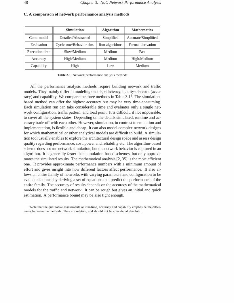
48 Chapter 3. NoC Network Performance Analysis
C. A comparison of network performance analysis methods
Simulation Algorithm Mathematics
Com. model Detailed/Abstracted Simplified Accurate/Simplified
Evaluation Cycle-true/Behavior sim. Run algorithms Formal derivation
Execution time Slow/Medium Medium Fast
Accuracy High/Medium Medium High/Medium
Capability High Low Medium
Table 3.1. Network performance analysis methods
All the performance analysis methods require building network and trafficmodels. They mainly differ in modeling details, efficiency, quality-of-result (accu-racy) and capability. We compare the three methods in Table 3.11. The simulation-based method can offer the highest accuracy but may be very time-consuming.Each simulation run can take considerable time and evaluates only a single net-work configuration, traffic pattern, and load point. It is difficult, if not impossible,to cover all the system states. Depending on the details simulated, runtime and ac-curacy trade off with each other. However, simulation, in contrast to emulation andimplementation, is flexible and cheap. It can also model complex network designsfor which mathematical or other analytical models are difficult to build. A simula-tion tool usually enables to explore the architectural design space and assess designquality regarding performance, cost, power and reliability etc. The algorithm-basedscheme does not run network simulation, but the network behavior is captured in analgorithm. It is generally faster than simulation-based schemes, but only approxi-mates the simulated results. The mathematical analysis [2, 35] is the most efficientone. It provides approximate performance numbers with a minimum amount ofeffort and gives insight into how different factors affect performance. It also al-lows an entire family of networks with varying parameters and configuration to beevaluated at once by deriving a set of equations that predict the performance of theentire family. The accuracy of results depends on the accuracy of the mathematicalmodels for the traffic and network. It can be rough but gives an initial and quickestimation. A performance bound may be also tight enough.
1Note that the qualitative assessments on run-time, accuracy and capability emphasize the differ-ences between the methods. They are relative, and should not be considered absolute.

3.1. Introduction 49
As simulation is most powerful, once it is verified, it is typically used to vali-date the algorithm-based and formalism-based approaches. In the next subsection,we outline current practices of NoC simulation.
3.1.2 Practices of NoC Simulation
NoC researchers have used general-purpose network simulators and NoC-specificsimulators to simulate the network behavior. OPNET is a commercial network sim-ulator used in [15, 133]. It provides a tool for hierarchical modeling and includesprocesses, network topology description and supports different traffic scenarios.However, to simulate an on-chip network, it has to be adapted by explicitly mod-eling synchronous operations and distribution [133]. OMNET is an open-sourceC++-based network simulation engine. It is used in [89] to validate a network con-tention model proposed in [69]. As with OPNET, additional modules are neededto model synchronous network operations in OMNET. Semla [125, 126] is a dedi-cated NoC simulator written in SystemC [20]. It implements five layers of the OSIseven-layer model (without the presentation and session layers), and is equippedwith transaction-level primitives to communicate messages between applicationprocesses. The SystemC kernel provides the concurrent and synchronous opera-tion semantics, thus a SystemC-based network simulator can take this advantage.In [8], a VHDL-based RTL model is created for evaluating power and performanceof NoC architectures. It can model dynamic and leakage power at the system-level. The Orion [131] performance-power simulator models only the dynamicpower consumption.
OCCN (On Chip Communication Network) [21] models on-chip network com-munication in SystemC using high-level modeling concepts such as transactionsand channels. In [77], an on-chip communication network is treated as a com-munication processor to reflect servicing demands. The network is modeled us-ing allocators, schedulers and synchronizers. The allocator decides the resourcerequirements such as bandwidth and buffers along a message’s path while mini-mizing resource conflict. The scheduler executes the message transfer accordingly,minimizing the resource occupation. The synchronizer performs synchronizationaccording to dependencies among messages while allowing concurrency. In [32],network communication is defined as a multiport blackbox communication struc-ture. A message can be transmitted from an arbitrary port to another but the actualimplementation of the NoC may not be considered.
Next, we present our NoC simulation tool NNSE in Section 3.2. In Section 3.3,we present our algorithm-based network performance analysis, focusing on the fea-

50 Chapter 3. NoC Network Performance Analysis
sibility test of delivering real-time messages, i.e., whether their timing constraintscan be met or not.
3.2 NNSE: Nostrum NoC Simulation Environment
3.2.1 Overview
NNSE stands for Nostrum NoC Simulation Environment in which Nostrum is thename of our NoC concept [81]. NNSE is aimed to be a tool for full NoC sys-tem simulation so that designers can use it to explore the architecture-level andapplication-level design space. Currently, it is capable of
• constructing network-based communication platforms [125],
• generating synthetic and semi-synthetic Traffic Patterns (TPs) [68],
• simulating the communication behavior with the various TPs [76], and
• mapping application tasks onto the platform [71].
The first three functions have been automated and the last function is so fara manual step. The automation is achieved through parameterizing network andsynthetic traffic configurations. One can configure these parameters, recompilethe program if the parameters are compile-time, and invoke simulations with thespecified network and traffic configurations. This procedure can be conducted in aGraphical User Interface (GUI). With the GUI, the tool allows us to easily exploredifferent network architectures and different traffic settings. Network architecturescan thus be efficiently and extensively evaluated. In addition to using synthetictraffic, the manual application mapping creates realistic traffic scenarios in thecommunication platform. The evaluation may be iterative by applying the con-figured or created traffic on the configured networks, as illustrated in Figure 3.1.The evaluation criteria can be performance, power and cost. The current versionevaluates only the network performance in terms of packet latency, link utilizationand throughput. Since it simulates the network behavior at the flit-level cycle-by-cycle, the performance estimates are accurate.
NNSE logically comprises a NoC simulation kernel [124, 125] wrapped witha GUI. The kernel is developed in SystemC and the GUI written in Python. Fol-lowing the ISO’s OSI seven-layer model [135], the simulation kernel called Semla(Simulation EnviornMent for Layered Architecture) implements five of the sevenlayers except for the representation and session layers. The simulation tool presently

3.2. NNSE: Nostrum NoC Simulation Environment 51
Network 2Network 1 Network n
TP1 TP2 TPn
Figure 3.1. Network evaluation
supports the configuration of the network and application layers in the GUI. Theconfiguration of the application layer refers to the traffic configuration. In the GUI,all the network and traffic configurations can be stored and thus reusable. To facil-itate data exchange, they are stored as eXtensible Markup Language (XML) files.The simulation results can be shown graphically or in a text format.
3.2.2 The Simulation Kernel
The simulation kernel Semla [124, 125] implements the five communication layers,namely, the physical layer (PL), the data link layer (LL), the network layer (NL),the transport layer (TL) and the application layer (AL). The upper three layers areshown in Figure 3.2, where TG/S stands for Traffic Generator/Sink, and Glue isthe TL component which does packetization/packet-assembly, message queuing,multiplexing, de-multiplexing and so on.
TG/S TG/S TG/S
TG/S
Glue Glue Glue
NetworkNL
TL
AL
messages
packets
TL interface
Platform
Figure 3.2. The communication layers in Semla
The transport layer provides transaction-level communication primitives as aninterface to enable communication via channels between application processes. Achannel, similar to a SystemC channel [20], is a transaction-level modeling en-tity which allows simplex communication from a source process to a destination

52 Chapter 3. NoC Network Performance Analysis
process. In Semla, a compact set of message passing primitives for using the best-effort service is defined and implemented:
• int open channel(int src pid, int dst pid): it opens a simplex channel from asource process src pid to a destination process dst pid. The method returnsa positive integer as a unique channel identity number cid upon successfullyopening the channel. Otherwise, it returns a negative integer for variousreasons of failure, such as invalid source and destination processes. Thecurrent implementation opens channels statically during compile time andthe opened channels are never closed through simulation.
• bool nb write(int cid, void msg): it writes msg to channel cid. The size ofmessages is finite. It returns the status of the write. The write is nonblocking.
• bool nb read(int cid, void *msg): it reads channel cid and writes the receivedprotocol data unit to the address starting at msg. It returns the status of theread. The read is nonblocking.
Application tasks use the set of communication primitives to communicatemessages with each other. While mapping tasks onto the NoC platform, the net-work topology is visible. The communication part of the tasks must be written in oradapted to the communication primitives. The interaction between the tasks createsrealistic workload in the platform, and the system behavior can be simulated.
Thanks to the layering, one can design and implement different structures andprotocols in a layer without modifying other layers as long as one complies withthe interfaces. For instance, Semla originally developed the network layer for de-flection routing. In order to perform experiments on flit-admission and flit-ejectionschemes in Chapter 2, the network layer for wormhole switching was developedand integrated into the simulator. The physical layer was skipped because the in-terest was on the flit-level not the phit-level activities. While the compilation andsimulation were invoked, only the network layer entity was replaced while the up-per layers remained the same.
3.2.3 Network Configuration
We parameterize a network according to topology, switching mode and routing al-gorithm. The network configuration is thus straightforward, as illustrated by thetree in Figure 3.3. The topology is for a 2D regular structure, which can be di-mensioned along the number of nodes on the X axis, the number of nodes on theY axis. The structure may be chosen from one of the options (mesh, torus, tree,

3.2. NNSE: Nostrum NoC Simulation Environment 53
or
and
SwitchingTopology
Network
(name, size, interface)
(routing algorithm)
link bandwidth)connectionstructure
Routing(mode: deflection | wormhole)
(VC number, VC depth)wormhole_routing
(num_nodes_X, num_nodes_Y,(mesh | torus | tree | ring),
(simplex | duplex),
deflection_routing(deflection policy)
Figure 3.3. Network configuration tree
ring). The link connection may be simplex or duplex with different data width. Thenetwork parameters may be further elaborated resulting in the next level in the treesince each of them has a number of choices on its own. As can be seen, with thedeflection scheme, different deflection polices may be chosen; with the wormholescheme, the number and depth of virtual channels (VCs) may be specified.
3.2.4 Traffic Configuration
This subsection summarizes the research in Paper 5.
A. Traffic configuration approaches
Network evaluation typically employs application-driven and synthetic traffic [28].Application-driven traffic models the network and its clients simultaneously. Thisis based on full system simulation and communication traces. Full system sim-ulation requires building the client models. Application-driven traffic can be toocumbersome to develop and control. In NNSE, application-driven traffic is createdby mapping application tasks onto the communication platform. Synthetic trafficcaptures the prominent aspects of the application-driven workload but can also beeasily designed and manipulated. Because of this, synthetic traffic is widely usedfor network evaluation.
In NNSE, two types of traffic can be configured. One is purely synthetic traffic,the other application-oriented traffic. For synthetic traffic, we proposed a unifiedformal expression for both uniform and locality traffic. With this expression, wecan control the locality of traffic distribution by setting locality factors for the traf-fic. The application-oriented traffic is semi-synthetic, which can be viewed as a
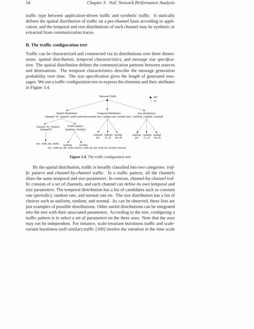
54 Chapter 3. NoC Network Performance Analysis
traffic type between application-driven traffic and synthetic traffic. It staticallydefines the spatial distribution of traffic on a per-channel basis according to appli-cation, and the temporal and size distributions of each channel may be synthetic orextracted from communication traces.
B. The traffic configuration tree
Traffic can be characterized and constructed via its distributions over three dimen-sions: spatial distribution, temporal characteristics, and message size specifica-tion. The spatial distribution defines the communication patterns between sourcesand destinations. The temporal characteristics describe the message generationprobability over time. The size specification gives the length of generated mes-sages. We use a traffic configuration tree to express the elements and their attributesin Figure 3.4.
or
and
Temporal distribution
Network Traffic
(constant rate | random rate | normal rate)Spatial distribution
uniform locality
(uniform | locality)Traffic pattern
(channel*)Channel−by−channel
(src. node, dst. node)
(src. node set, dst. node set, locality factors)(src. node set, dst. node set)
(channel−by−channel | traffic pattern)Size distribution
(uniform | random | normal)
(m, d)normalrandom
(n) [1, n]constant random
[1, n]normal(m, d)(n)
uniform
Figure 3.4. The traffic configuration tree
By the spatial distribution, traffic is broadly classified into two categories: traf-fic pattern and channel-by-channel traffic. In a traffic pattern, all the channelsshare the same temporal and size parameters. In contrast, channel-by-channel traf-fic consists of a set of channels, and each channel can define its own temporal andsize parameters. The temporal distribution has a list of candidates such as constantrate (periodic), random rate, and normal rate etc. The size distribution has a list ofchoices such as uniform, random, and normal. As can be observed, these lists arejust examples of possible distributions. Other useful distributions can be integratedinto the tree with their associated parameters. According to the tree, configuring atraffic pattern is to select a set of parameters on the three axes. Note that the axesmay not be independent. For instance, scale-invariant burstiness traffic and scale-variant burstiness (self-similar) traffic [100] involve the variation in the time scale

3.2. NNSE: Nostrum NoC Simulation Environment 55
and message size, thus requiring the synergy between the temporal distribution andthe size distribution.
C. Representation of traffic patterns
As shown in Figure 3.4, the traffic patterns consist of uniform and locality traffic.They can be uniformly expressed in a formal representation.
We first define communication distribution probability DP from node i to nodej DPi→j as the probability of distributing messages from node i to node j whilenode i sends messages to the network. Suppose, there are N nodes in the network,Equation 3.1 means that all messages from node i are aimed to the N destinationnodes.
N∑j=1
DPi→j = 1 (3.1)
Next, we relate DP to the minimal distance between nodes. Let the shortestdistance between a source node i and a destination node j be d, we define com-munication distribution probability DPi→j as a relative probability to a commonprobability factor Pc (0 ≤ Pc ≤ 1) in Equation 3.2.
DPi→j = coef (α, d) · Pc (3.2)
where coef (α, d) = 1 +α
d + 1In the equation, coef is the distribution coefficient and α called locality factor.
Since DPi→j ≥ 0, α ≥ −(d + 1). Particularly when α = −(d + 1), DPi→j =0; when α = 0, DPi→j = Pc. Besides, when −(d + 1) < α < 0, DPi→j
is proportional to distance d; When α > 0, DPi→j is inversely proportional todistance d. In addition, α(d) can be defined for each possible value of distance d.
Using the traffic expression, the locality of traffic distribution can be easilycontrolled by setting α(d) for each possible distance value d. For instance, ifα(d) = −(d + 1), coef(−(d + 1), d) = 0 meaning that no traffic is generatedbetween sources and destinations if their shortest distance is d; if α(0) = −1 ford = 0, coef(−1, 0) = 0, meaning that no self-loop traffic is created. If we set“α(d) = 0” for all possible values of d in the network, their distribution coeffi-cients coef (0, d) = 1. Then for any source node i, it has an equal probability todistribute traffic to any node j. In this case, the traffic distribution is independent ofdistance d, meaning that the traffic is uniform. After setting α(d), we can calculatecoef (α, d) and Pc using Equations 3.1 and 3.2. Then DP (d) can be derived. Anexample of the calculation is given in Paper 5.

56 Chapter 3. NoC Network Performance Analysis
D. Channel-by-channel traffic
For the traffic patterns, we control the traffic generation and locality by setting a lo-cality factor α for each possible distance d. Since one distance may cover a numberof pairs of source and destination nodes, we avoid specifying the communicationdistribution probabilities for each source node to each and every possible desti-nation node. For channel-by-channel traffic, as the name suggests, we set trafficparameters for each individual channel. The set of traffic parameters of a channelis {s proc, d proc, T, S}, where s proc represents the source process, d proc thedestination process, T its temporal characteristics, and S its message size specifi-cation. For each channel, we can determine the source node for s proc and thedestination node for d proc after the application task graph is mapped onto thenetwork nodes. The temporal characteristics T and the message size specificationS can be synthetically configured using the same set of options in the tree or ap-proximated using analysis or communication traces [68].
Channel-by-channel traffic differs from the traffic patterns mainly in that thetraffic’s spatial pattern is statically built on a per-channel basis according to an ap-plication task graph. Since the communication pattern in the task graph is captured,this type of traffic is used to construct application-oriented workloads.
3.2.5 An Evaluation Case Study
As a case study (Paper 6), we have evaluated deflection networks in NNSE [76].A deflection-routed network (see Section 2.1 of Chapter 2) has three orthogonalcharacteristics: topology, routing algorithm and deflection policy. It is crucial toexplore the alternatives of the three aspects since the decisions on these aspectsmay be hardwired and may not be dynamically configurable or too costly to permitdynamic configuration. Therefore identifying the significance of each factor andevaluating their alternatives play a vital role in the decision-making.
In the evaluation, we have considered 2D regular topologies such as mesh,torus and Manhattan Street Network, different routing algorithms such as random,dimension XY, delta XY and minimum deflection, as well as different deflectionpolicies such as non-priority, weighted priority and straight-through policies [76].Our results suggest that the performance of a deflection network is more sensitiveto its topology than the other two parameters. It is less sensitive to its routingalgorithm, but a routing algorithm should be minimal. A priority-based deflec-tion policy that uses global and history-related criterion can achieve both betteraverage-case and worst-case performance than a non-priority or priority policy thatuses only local and stateless criterion. These findings are important since they can

3.3. Feasibility Analysis of On-Chip Messaging 57
guide designers to make right decisions on the network architecture, for instance,selecting a routing algorithm or deflection policy which has potentially low costand high speed for hardware implementation.
3.3 Feasibility Analysis of On-Chip Messaging
This section summarizes the research in Paper 7.
3.3.1 Problem Description
Partitioning & Mapping
Feasibility analysis
NoC arch.
System spec. Process
Node
P0
P1 P2
P3 P4
N1 N2
N3 N4
Figure 3.5. Feasibility analysis in a NoC design flow
As illustrated in Figure 3.5, NoC design starts with a system specificationwhich can be expressed as a set of communicating tasks. The second step is topartition and map these tasks onto the resources of a NoC. With a mapping, ap-plication tasks running on these resources load the network with messages, and

58 Chapter 3. NoC Network Performance Analysis
impose timing constraints for delivering messages. The feasibility analysis is per-formed on the resulting NoC instance. Feasibility analysis could, on its own, covera wide range of evaluation criteria such as performance, power and cost. In ourcontext, we concentrate on the timely delivery of messages, which is essential forperformance and predictability.
Following [110], we distinguish real-time and nonreal-time messages in on-chip networks. Messages with a deterministic performance bound, which mustbe delivered predictably even under worst case scenarios, are real-time (RT) mes-sages. Messages with a probabilistic bound, which ask for an average responsetime, are nonreal-time messages. Our focus in the thesis is on the feasibility anal-ysis of delivering RT messages in a wormhole-switched network. We follow thefeasibility definition in [7]: Given a set of already scheduled messages, a messageis termed feasible if its own timing property is satisfied irrespective of any arrivalorders of the messages in the set, and it does not prevent any message in the set frommeeting its timing property. We resort to an algorithm-based instead of simulation-based approach in the analysis to avoid cycle-by-cycle simulations. Since it is thenetwork contention that makes the message delivery non-deterministic, we formu-late a contention tree model that captures direct and indirect network contentionsand reflects concurrency in link usage. Based on this model, we investigate mes-sage scheduling to estimate the worst-case performance for RT messages and de-velop an algorithm to conduct the feasibility analysis. The analysis returns the passratio, i.e., the percentage of feasible messages, and the network utilization of thefeasible messages.
In the following, we first describe the contention tree model, message schedul-ing on a contention tree, and then the feasibility analysis flow.
3.3.2 The Network Contention Model
A. The real-time communication model
Wormhole switching divides a message into a number of flits for transmission2.During the delivery, it manages two types of resources, the lanes and the link band-width. Lanes are flit buffers organized into several independent FIFOs instead of asingle FIFO. Lane allocation is made at the message level while link bandwidth isassigned at the flit level. In conventional wormhole switches, the shared lanes arearbitrated on First-Come-First-Serve (FCFS), and the shared link bandwidth aremultiplexed by the lanes. Messages are not associated with a priority and they areequally treated. This model is fair and produces average-case performance results.
2The effect of packetization is not considered here.

3.3. Feasibility Analysis of On-Chip Messaging 59
It is suitable to deliver nonreal-time messages, which do not require guarantees.But, it can not directly support real-time messages because there is no promisethat messages are delivered before deadlines. In order to enable guarantees, real-time messages must be served with other disciplines, for instance, priority-basedarbitrations [62].
We assume a conventional wormhole switch architecture and a priority-baseddelivery model for RT messages. Special RT communication services generallyrequire special architectural support which may potentially complicate the switchdesign. All messages are globally prioritized, and priority ties are resolved ran-domly. This model arbitrates shared lanes and link bandwidth on priority. Thepriority, which may be assigned according to rate, deadline or laxity [40, 62], takesa small number of flits. With this RT communication model, the worst-case latencyT rt of delivering a message of L flits is given by :
T rt = (L + Lpri)/Brt + HR + τ = T + τ (3.3)
where Brt is the link bandwidth allocated to the RT message along its route; H isthe number of hops from the source node to the destination node; R is the routingdelay per hop; Lpri is the number of flits used to express the message priority. Therouting delay R is assumed to be the same for head flits and body/tail flits. Thefirst term counts for the transmission time of all the message flits; the sum of thefirst two terms is the non-contentional or base latency T , which is the lower boundon T rt; the last term τ is the worst-case blocking time due to network contention.
B. Network contention
To estimate the worst-case latency T rt of an RT message M , we have to estimatethe worst-case blocking time τ . To this end, we first determine all the contentionsthe message may meet.
In flit-buffered networks, the flits of a message Mi are pipelined along its rout-ing path. The message advances when it receives the link bandwidth along thepath. The message may directly and/or indirectly contend with other messages forshared lanes and link bandwidth. Mi has a higher priority set Si that consists of adirect contention set SDi and an indirect contention set SIi , Si = SDi + SIi . SDi
includes the higher priority messages that share at least one link with Mi. Mes-sages in SDi directly contend with Mi. SIi includes the higher priority messagesthat do not share a link with Mi, but share at least one link with a message in SDi ,and SIi ∩ SDi = ∅. Messages in SIi indirectly contend with Mi. As an example,Fig. 3.6a shows a fraction of a network with four nodes and four messages. Themessages M1, M2, M3 and M4 pass the links AB, BC, AB→BC→CD, and CD,

60 Chapter 3. NoC Network Performance Analysis
respectively. A lower message index denotes a higher priority. The message M1
has the highest priority, thus S1 = ∅. For the message M2, it directly contends withM3, but it has a higher priority, thus S2 = ∅. The message M3 has a higher prioritymessage set S3 = SD3 = {M1, M2}, SI3 = ∅. For the message M4, SD4 = {M3}and SI4 = {M1, M2} because M1 or M2 may block M3 which in turn blocks M4.
B C DA
(a) (b)
M1
M1
M2M2
M3
M3M3
M3 M4
M4E13
E23
E34
Figure 3.6. Network contention and contention tree
C. The contention tree
To capture both direct and indirect contentions and to reflect concurrent schedulingon disjoint links, we have formulated a contention tree model that is defined as adirected graph G : M × E. A message Mi is represented as a node Mi in thetree. An edge Eij(i < j) directs from node Mi to node Mj , representing the directcontention between Mi and Mj . Mi is called parent, Mj child. Given a set n ofRT messages, after mapping the messages to the target network, we can build acontention tree with the following three steps:
Step 1. Sort the message set in descending priority sequence with a chosen prior-ity assignment policy.
Step 2. Determine the routing path for each of the messages.
Step 3. Construct a tree, starting with the highest priority message M1, and thenM2...Mn. If Mi shares at least one link with Mj where i < j ≤ n, an edgeEij is created between them. Each node in the tree only maintains a list ofits parent nodes.
In a contention tree, a direct contention is represented by a directed edge whilean indirect contention is implied by a walk via parent node(s). A walk is a pathfollowing directed edges in the tree. The contention tree for Fig. 3.6a is shown inFig. 3.6b, where the three direct contentions are represented by the three edges E13,E23 and E34, and the two indirect contentions for M4 are implied by the two walksE13 → E34 and E23 → E34 via M4’s parent node M3. Since determining the

3.3. Feasibility Analysis of On-Chip Messaging 61
routing path is a priori, creating a contention tree is more suitable for deterministicrouting. For adaptive routing, it is difficult to figure out the worst-case routing path.
D. Assumptions and simplifications
The estimation of latency bounds are based on messages’ schedules on links. Aschedule is a timing sequence where a time slot is occupied by a message or leftempty. The latency bound of a message is the earliest possible completion time fordelivery under the worst case. Before introducing schedules of messages, we listthe assumptions, limitations and simplifications as follows:
• The messages we consider are periodic and independent. There is no datadependency among messages so that each message can be periodically firedor activated, meaning that the messages are sent to the network and start tocompete for shared resources, i.e., buffers and links.
• We focus on link contentions. Similarly to [7, 40], we assume that thereis a sufficient number of Virtual Channels (VCs) so that priority inversiondue to VC unavailability does not occur. Priority inversion happens whena message with a lower priority holds shared resources, leading to blockingmessages with a higher priority. As discussed in [7, 40], this problem can bealleviated by packetization.
• In this communication model, messages are allocated with time slots de-pending on their priorities and contentions. Whenever there is a contentionfor a link, a message with a higher priority will be scheduled first. In addi-tion, a higher priority message can preempt a lower priority message.
• The worst case is assumed to occur when all the messages are fired into thenetwork at the same time.
• The bandwidth of a link is assumed to transmit one flit in one time slot. Therouting delay per hop takes one time slot. We simplify the pipeline latencyon links so that the flits of a message are available to compete all the linkbandwidth along the message’s path simultaneously for the duration of itscommunication time. To explain this, we illustrate a message transmissionin Figure 3.7, where M2 passes through three hops (A, B, C) and two links(AB, BC). M2 contains four flits (one head h flit, two body b flits and onetail t flit). It has a base latency of 7 (1 · 3 + 4). If M2 fires at time instant 0,by the assumption, it will compete for both links AB and BC from slot 1 to7, i.e., for its entire base latency period.

62 Chapter 3. NoC Network Performance Analysis
B CA
t=1t=2t=3t=4t=5t=6t=7
0
M2M2
b1
b1
b1
b1
b2
b2
b2
b2
hh
hh
tt
tt
Figure 3.7. Message contention for links simultaneously
• We assume that a message advances only if it simultaneously receives allthe link bandwidth along its path. This means that the flits are deliveredeither concurrently via the links or blocked in place. As a result, a messagecompetes for links only for its base latency period. It does not happen thata flit advances via a link while another flit is blocked in place. As shown inFigure 3.8, at time slot 3, the head flit h has advanced from node B to C butthe first body flit b1 is blocked in node A. As a consequence, the pipelinelatency is increased by one slot. According to our assumption, this scenarioin time slot 3 is avoided and thus not considered. Apparently, if flits areindividually routed via links, the contention period may become larger thanits base latency and unpredictable.
E. Scheduling on the contention tree: an example
Table 3.2 shows an example of message parameters for Fig. 3.6, where the priorityis assigned by rate, and the deadline D equals period p. The worst-case schedulesfor the three links are illustrated separately in Fig. 3.9a. Initially, all messages arefired. M1 is allocated 7 slots on link AB. M2 is allocated 3 slots on link BC. M3
is blocked by M1 and M2. M4 is blocked by M3. After M1 and M2 completetransmission, M3 is allocated 3 slots concurrently on link AB, BC and CD. At timeslot 10, M1 fires again and holds slots [11, 17] on link AB, preempting M3. Attime slot 15, M2 fires the second time and holds slots [16, 18] on link BC. AfterM1 and M2 complete their second transmission, M3 continues its first transmis-sion by holding slots [19, 20]. After M3 finishes its first delivery, M4 is allocated

3.3. Feasibility Analysis of On-Chip Messaging 63
B CA
t=1t=2t=3
0
t=4t=5t=6t=7t=8
b1
b1
b1
b1
b1
b2
b2
b2
b2
hhh
hh
tt
tt
M2M2
Figure 3.8. Avoided flit-delivery scenario
Table 3.2. Message parameters and latency bounds
Message Period p Deadline D Base latency T Latency bound T rt
M1 10 10 7 7
M2 15 15 3 3
M3 30 30 5 20
M4 30 30 8 28
slots [21, 28] on link CD. M1 starts its third round and holds slots [21, 27] on linkAB. Since the four messages have a Least Common Multiple (LCM) period of 30,the four messages are scheduled in the same way at each LCM period. From theschedules, we can find that the latency bounds for M1, M2, M3, M4 are 7, 3, 20,28, respectively. Equivalently, the worst-case blocking times for the four messagesare 0, 0, 15, 20. The latency bounds for the four messages are also listed in Table3.2. We can see that all the four messages are feasible.
Looking into the schedules, we can observe that
(1) M1 and M2 are scheduled in parallel. This concurrency is in fact reflected bythe disjoint nodes in the tree. We call two nodes disjoint if no single walkcan pass through both nodes. For instance, M1 and M2 in Fig. 3.6b aredisjoint, therefore their schedules do not interfere with each other.

64 Chapter 3. NoC Network Performance Analysis
���������
���������
������������
������������
������������������������
��������
��������
���������
���������
link AB0 25 282010 15 305 37
Message fires
7 18
28200 1510 30 37
link BC
Message fires
0
link CD
2810 15 20 30 37
0 252010 155
0 10 15 20
200 1510
7 18 30
30
30
0 2810 15 20 30
Unroll 3 times
Unroll twice
Directly Indirectly
7 18
5 25
Message fires
(b) Global schedules of the messages
(a) Link schedules of the messages
Contended slots
M1 M1M1M1
M1
M1
M1
M1
M1M1
M2 M2 M2
M2
M2
M2 M2
M3 M3M3
M3
M3
M3M3
M3
M3
M4 M4
M4
M1, M3M1, M3
M2, M3M2, M3
M3, M4M3, M4
Figure 3.9. Message scheduling
(2) M3 is scheduled on the overlapped empty time slots [8, 10] and [19, 20] leftafter scheduling M1 and M2. This is implied in the tree where M3 has twoparents, M1 and M2. The contended slots [1,7] and [11,18] are occupiedby M1 or M2. A contended slot is a time slot occupied by a higher prioritymessage when the contention occurs. A contention occurs only when twocompeting messages are fired.
(3) M4 is scheduled only after M3 completes transmission at time 20. The indirectcontentions from M1 and M2, which are reflected via slots [1,7] and [11,18],propagate via its parent node M3. For M3, these slots are directly contended

3.3. Feasibility Analysis of On-Chip Messaging 65
slots. For M4, they become indirectly contended slots.
The four message schedules are individually depicted in Fig. 3.9b. If the direc-tion contention is not distinguished from the indirect contention as the lumped-linkmodel [7] does, M3 and M4 would be considered infeasible since M2 would oc-cupy the slots [8, 10] and [18, 20], leaving only three slots [28, 30] for M3 and M4.If the concurrent use of the two links, AB by M1 and BC by M2, was not properlycaptured as the blocking-dependency model [55] does, M3 and M4 would also beconsidered infeasible since M2 would occupy the slots [8, 10] and [18, 20] beforeslot 30.
In a contention tree, all levels of indirect contentions propagate via the inter-mediate node(s). This is pessimistic since many of them are not likely to occur atthe same time. Also, a lower priority message can actually use the link bandwidthif a competing message with a higher priority is blocked elsewhere.
The validation of the contention-tree model as well as the comparisons withother proposed contention models are provided in [89].
3.3.3 The Feasibility Test
A. The feasibility test algorithm
Based on the contention tree and priority-based message scheduling, each feasiblemessage obtains a global schedule. A message schedule is based on its parents’schedules. If a node has no parent or feasible parent, it is scheduled whenever itfires, thus it is always feasible. If a node has feasible parent(s), we must first markthe contended slots as occupied and then schedule the node.
(b)(a)
A CBM1
M1M2
M2
M2
M3
M3
E12 E23
Figure 3.10. A three-node contention tree
Note that a slot occupied by a higher priority message is not necessarily a con-tended slot. Consider the contention tree in Figure 3.10 where the three messagesuse the parameters in Table 3.2. The message schedules are depicted in Figure3.11. M1 has the highest priority and schedules whenever it fires. Consider theLCM period for the three messages, which is 30 in this case, M1 fires three timesand occupies slots [1, 7], [11, 17] and [21, 27]. M2 fires twice at time 0 and 15.

66 Chapter 3. NoC Network Performance Analysis
������������
������������
���������
���������
������������������������
������������������������
0 10 15 30 377 18
0 10 15 20 30 377 18
0 252010 155 30 37
M1 M1 M1M1M1
M2M2 M2
M3M3
Figure 3.11. Message scheduling and contended slots
Although the slots [10, 15] and [21, 27] are occupied by M1, M1 does not contendwith M2 during these time slots since M2 is not fired or has already been sched-uled. The directly contended slots with M1 are slots [1, 7] and [16, 17], implyingthat M2 can not be scheduled on these slots. Hence, M2 schedules on slots [8, 10]and [18, 20]. M3 fires once at time 0. The contended slots are [1, 7] (indirectlywith M1) and [8, 10] (directly with M2). Hence, M3 is scheduled on slots [11,15]. In summary, a slot is regarded as a contended slot only if two conditions aretrue: (1) it is occupied by a higher-priority message; (2) competing messages mustfire at the time slot. Particularly, for indirectly contended slots, the intermediatemessage(s) must also fire in order to pass the contention downwards; otherwise,the slots are not contended. As illustrated in Figure 3.11, for M3, slots [11, 15] areoccupied by M1 but not contended slots, since M2 are not fired during these slots.Therefore M3 is scheduled on these slots.
The indirect contentions propagate via parent nodes. Disjoint nodes are sched-uled concurrently. If a node M has k feasible parents, M can only be scheduled onthe overlapped empty or free (non-contended) slots of the k parents’ schedules. Thefeasibility of a message can be determined by comparing the number N of emptyslots available for scheduling M with its non-contentional or base latency T . Wedistinguish messages with a deadline constraint D or a jitter constraint J . For adeadline constrained message, its latency bound T rt must satisfy T rt ≤ D; For ajitter constrained message, its latency bound T rt must satisfy D − J ≤ T rt ≤ D.For a message M with a base latency T , we denote that the number of availableslots for scheduling M before its jitter range D − J and before its deadline Dis NJ and ND, respectively. If M is deadline-constrained and T ≤ ND, M isfeasible (feasible(M )=1); otherwise, M is infeasible (feasible(M )=0). If M isjitter-constrained and NJ ≤ T ≤ ND, M is feasible; otherwise, M is infeasible.
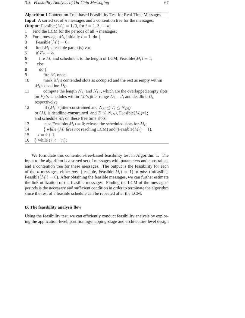
3.3. Feasibility Analysis of On-Chip Messaging 67
Algorithm 1 Contention-Tree-based Feasibility Test for Real-Time MessagesInput: A sorted set of n messages and a contention tree for the messages;Output: Feasible(Mi) = 1/0, for i = 1, 2, · · ·n;1 Find the LCM for the periods of all n messages;2 For a message Mi, initially i = 1, do {3 Feasible(Mi) = 0;4 find Mi’s feasible parent(s) FP ;5 if FP = φ6 fire Mi and schedule it to the length of LCM; Feasible(Mi) = 1;7 else8 do {9 fire Mi once;10 mark Mi’s contended slots as occupied and the rest as empty within
Mi’s deadline Di;11 compute the length NJi and NDi, which are the overlapped empty slots
on FP ’s schedules within Mi’s jitter range Di − Ji and deadline Di,respectively;
12 if (Mi is jitter-constrained and NJi ≤ Ti ≤ NDi)or (Mi is deadline-constrained and Ti ≤ NDi), Feasible(Mi)=1;and schedule Mi on these free time slots;
13 else Feasible(Mi) = 0; release the scheduled slots for Mi;14 } while (Mi fires not reaching LCM) and (Feasible(Mi) = 1);15 i = i + 1;16 } while (i <= n);
We formulate this contention-tree-based feasibility test in Algorithm 1. Theinput to the algorithm is a sorted set of messages with parameters and constraints,and a contention tree for these messages. The output is the feasibility for eachof the n messages, either pass (feasible, Feasible(Mi) = 1) or miss (infeasible,Feasible(Mi) = 0). After obtaining the feasible messages, we can further estimatethe link utilization of the feasible messages. Finding the LCM of the messages’periods is the necessary and sufficient condition in order to terminate the algorithmsince the rest of a feasible schedule can be repeated after the LCM.
B. The feasibility analysis flow
Using the feasibility test, we can efficiently conduct feasibility analysis by explor-ing the application-level, partitioning/mapping-stage and architecture-level design

68 Chapter 3. NoC Network Performance Analysis
Application task graph
START
messages
Task partitioning
Message priority policy
Feasibility test
Satisfied?
END
N
Y
Build contention tree
Message mappingTopology
Routing algorithm
messages and contentions
Pass ratio and network utilization
Message characterization
Figure 3.12. A feasibility analysis flow
space. Figure 3.12 shows a feasibility analysis flow. First, we partition the tasksand then characterize the messages from the application task graph. Then we builda contention tree. Since the contention tree is affected by several design decisionssuch as task partitioning, priority policy, message mapping strategy and the routingalgorithm etc., we can build different contention trees by exploring these possibil-ities. After creating a contention tree, the feasibility test algorithm can performthe analysis. The outcome of the test is the pass ratio and network utilization offeasible messages. These two measures may serve as the criteria to calibrate thedesign decisions. Clearly, this procedure is iterative until satisfaction.

3.4. Future Work 69
3.4 Future Work
NNSE has been demonstrated in the University Booth EDA (Electronic Design Au-tomation) Tool Program of DATE 2005 [73]. After publicity, it has been requestedfor research use by a number of NoC research groups in Europe, U.S.A. and Asia.In the future, we plan to improve it in the following directions:
• Parameterize more layers: Current tunable parameters include topology,routing, and switching schemes. Each of the parameters may be extendedwith more options. These are all network-layer parameters. In NNSE, thelayered structure allows us to orthogonally consider other layers’ parame-ters. In the physical layer, we can build wire, noise and signaling modelsto examine the reliability and robustness issues. We may consider the linklayer parameters such as the link capacity, link-level flow control schemesetc. The upper layer like the transport layer allows us to investigate bufferdimensioning and buffer sharing schemes, as well as end-to-end flow controlmethods.
• Configure dependent traffic: We have so far configured independent traf-fic, both synthetic and semi-synthetic. This means that traffic from differentchannels is independent from each other. This is easy to control and generate,but realistic traffic exhibits dependency and correlation. The way to gener-ate traffic with various dependencies such as data, control, time, causalityetc. is worth investigating. For example, traffic with the requirement of lip-synchronization shows correlated delivery requirements on video and audiotraffic streams.
• Support Quality-of-Service (QoS): This requires the implementation of QoSin the communication platform, and accordingly QoS generators and sinks.Monitoring service may be necessary to collect statistics on whether the per-formance constraints of a traffic stream have been satisfied or not.
• Integrate application mapping: A tool that only explores communicationperformance is not sufficient. System performance is the result of interactiveinvolvement of both communication and computation. Therefore, supportingapplication-mapping onto NoC platforms is surely desirable. To this end, weneed to build and/or integrate resources models for cores, memories and I/Omodules.
• Incorporate power estimation: As power is as sensible as performance for aquality SoC/NoC product, NNSE should incorporate the estimation of power

70 Chapter 3. NoC Network Performance Analysis
consumption so that the performance and power tradeoffs can be better in-vestigated and understood.
Extending further the traffic generation for performance evaluation ends upwith benchmarking different on-chip networks. The diverse NoC proposals neces-sitate standard sets of NoC benchmarks and associated evaluation methods to fairlycompare them.

Chapter 4
NoC Communication Refinement
This chapter presents our NoC communication refinement approach [Paper 8, 9].We start with a system model specified in the synchronous model of computation.Through a top-down procedure, we refine the communication in the system modelinto NoC communication via the communication interface of a NoC platform.
4.1 Introduction
4.1.1 Electronic System Level (ESL) Design
The rapid advancement of technology constantly fuels the SoC revolution [79]. Aswe mentioned previously, the state-of-the-art SoC design methodologies cannotsufficiently exploit the abundant transistor capacity. An on-going trend to shrinkthe productivity gap is Electronic System Level (ESL) design. This trend is mixedwith the platform-based design concept [54] and the promotion of using formalmodels for system specification and verification.
Traditional Register Transfer Level (RTL) for hardware design, which was in-troduced in the 90s, allows synthesized standard cell design. A synthesizable RTLdescription is presently often the starting point for an ASIC/FPGA design flow. Thedesign productivity cannot keep pace with the exponential expansion of the numberof transistors on a chip. Traditional C-based design for embedded software devel-opment shows even slower enhancement in design productivity. To shrink the gapbetween the design capability and the chip capacity, raising the design abstraction-level is an essential step forward. The current activities in Electronic System Level(ESL) [29] is consistent with this direction. The ITRS [46] defined ESL to be a
71

72 Chapter 4. NoC Communication Refinement
level above RTL, that consists of “a behavioral (before hardware/software partition-ing) and architectural level (after)”. The ESL raises the abstraction level in whichsystems are expressed. A system-level design allows larger function-architectureco-exploration [63], which is more than traditional hardware-software codesign.The final implementation can benefit in performance and cost. Using system-levelmodels, hardware and software design can be developed in parallel. This breaksthe sequential flow of hardware-first-software-second, thus compressing the de-sign cycle. Besides, the benefits of ESL include enabling new levels of designreuse and offering design chain integration across tool flows and abstraction levels.Using formal models is also advocated for system-level design [54, 116, 118]. Asnoted in [54], using formal models and transformations in system design is pro-moted so that verification and synthesis can be applied to advantage in the designmethodology. Verification, which is a key design activity, is effective if complexityis handled by formalization, abstraction and decomposition. Besides, the conceptof synthesis can be applied only if the precise mathematical meaning of a systemspecification is defined.
A formal model is associated with Models of Computation (MoCs). As de-fined in [118], a MoC refers to mathematical models that specify the semantics ofcomputation and of concurrency. Loosely defined, MoC specifies the operationalsemantics governing how processes interact with each other. There are a variety ofMoCs that exist for embedded system design, such as finite state machines [39],Petri nets [86], Kahn process networks [51], and synchronous models [11, 12] etc.A comprehensive digest of the various models can be found in [31, 118]. Thetagged-signal model [59] defines a denotational, semantic framework of signalsand processes within which models of computation can be studied and compared.In [48], a formal classification and description of these models is presented com-prehensively. Essentially, how time and concurrency are expressed distinguishesone MoC from another.
4.1.2 Communication Refinement
Communication refinement is a key step in a system-level design approach. It isa top-down process of synthesizing abstract communication in the system modelinto concrete communication in the system implementation architecture [31, 54].Abstraction defines the type of information present in a model. Unlike hierarchy,abstraction is not concerned with the amount of information visible, but with thesemantic principles of a model. In general, the movement from high to low ab-straction levels involves a decision-making process. By making design decisionsand increasing information about implementation details, we replace more abstract

4.1. Introduction 73
models with less abstract models, until the system is manufacturable. Through therefinement process, system properties and application constraints must be incorpo-rated and satisfied.
Communication refinement may be conducted in the functional domain or inthe implementation domain and usually comprises well-defined steps. A systemmodel, after steps of refinement, is derived into a refined model. The three keyissues for refinement are correctness, constraint and property satisfaction and ef-ficiency. As the refined model is an elaborate version of the original model, theymust be functionally equivalent. This is achieved by preserving semantics duringrefinement, i.e., a refinement step should not introduce semantic deviation. Thesecond requirement means that the refined, correct model must satisfy design con-straints for performance and ensure properties to achieve design objectives. Thethird one here refers to resource consumption in the system implementation archi-tecture. It can be very specific, depending on whether our application is aimed forlow power or low cost.
In the NoC case, the communication architecture is preferably predefined asa platform and the Application Level Interface (ALI), which provides primitivesfor inter-process communication, is the only way to access the communicationservices. The NoC communication refinement is therefore to refine the abstractcommunication in a system specification onto the NoC platform via the ALI. Wehave proposed a three-step top-down procedure to refine the communication of asystem model specified in the synchronous MoC into NoC communication. Beforewe present the refinement steps, we introduce the synchronous MoC.
4.1.3 Synchronous Model of Computation (MoC)
A. Synchronous modeling paradigm
The synchronous modeling paradigm [11, 12] is based on an elegant and simplemathematical model, which has been shown successful and is the ground of syn-chronous languages [38] such as Esterel, Signal, Argos and Lustre. The basis is theperfect synchrony hypothesis, i.e., both computation and communication take non-observable time. The critical requirement from specification to implementation isthat the implementation has to be fast enough both in communication and computa-tion. This means that the implementation phase has to take worst-case into account.Synchronous MoC was initially introduced for reactive and safety-critical embed-ded control systems where reasoning about the functional correctness is supreme.It has to verify that at each tick over time the system works properly.

74 Chapter 4. NoC Communication Refinement
In a synchronous MoC, a system is modeled as a set of fully concurrent com-municating processes via signals. Processes use ideal data types and assume infi-nite buffers. By following the tagged-signal model [59], a signal can be defined asa set of ordered events, with each event taking a value and a tag. The value is theinformative data to be communicated, and the tag indicates a time slot. This meansthat each event is conceptually and explicitly accompanied by a time slot to conveydata. If the data contains a useful value, the event is present and called a token;otherwise, the event is absent and modeled as a 1 representing a clock tick. Withthe introduction of , multi-rate systems can be modeled since every nth event inone signal aligns with the events in another. A synchronous MoC is a timed MoCwhere events are globally and totally ordered. Each signal can be related to thetime slots of another signal in an unambiguous way. The output events of a pro-cess occur in the same time slot as the corresponding input events. Moreover, theyare instantaneously distributed in the entire system and are available to all otherprocesses in the same slot. Receiving processes in turn consume the events andemit output events again in the same time slot. Processes can thus be viewed ascommunicating events via an ideal channel, which is delay-free. In addition, theideal channel is buffer-less and has unlimited bandwidth because any type of eventvalues passes through it instantaneously. This communication channel is in con-trast to that of other MoCs. For example, the Kahn and dataflow process networks[58] assume unbounded FIFO channels between actors (processes).
Two events are synchronous if they have the same tag. Two signals are syn-chronous if each event in one signal synchronous with an event in the other signaland vice versa. A process is synchronous if every signal of the process is syn-chronous with every other signal of the process. A system is synchronous if allprocesses are synchronous locally and globally (synchronous with each other). Asystem specified in the synchronous paradigm is a synchronous system. For feed-back loops, the perfect synchrony leads to cyclic dependency between an inputsignal and an output signal. If such cyclic communication is allowed in system be-havior, some mechanism must be used to resolve it. One possibility is to introducea delay in the output signal. Another possibility is to use fixed-point semantics,where the system behavior is defined as a set of events that satisfy all processes.The third possibility is to leave the results undefined, resulting in nondetermin-ism or infinite computation within one tick. If only one precise result is definedfor a feedback loop using the delayed time tag, a synchronous model is determin-
1In Paper 9, we used ⊥ (pronounced “bottom”) to represent absent. Since ⊥ has been used indataflow process networks to represent don’t-care [58], we later used � in Paper 8 to represent absentin order to distinguish it from ⊥. This notation is also consistent with [48].

4.1. Introduction 75
istic, i.e., given the same input sequence of events, it generates the same outputsequences of events.
B. The ForSyDe methodology
ForSyDe stands for FORmal SYstem DEsign. It is a system-level design methodol-ogy for SoC applications developed in the Royal Institute of Technology, Sweden.The ForSyDe methodology [116] is based on the synchronous MoC. It uses pro-cess constructors to cleanly separate communication from computation. Commu-nication is captured by the process constructors and computation by the functionof the processes. It employs transformations in the functional domain to refine asystem model into a less-abstract model optimized for implementation [115, 117].The transformations, which are conducted step by step, can be either semantic-preserving or a design decision. Semantic-preserving transformations are correctby construction while design decision is not. But, formal verification of designdecisions is possible by defining an appropriate notion of equivalence [108]. Af-ter refinement, the refined model is partitioned into hardware and software andmapped onto the implementation architecture [70]. In ForSyDe, the zero-delayfeedback is forbidden. A delay is introduced in the feedback loop. ForSyDe usesthe functional language Haskell [127] to express its system models. The modelsare executable.
Our refinement approach has been conducted in the ForSyDe framework inorder to experiment and validate our concepts with executable models, but ourrefinement approach applies also to a general synchronous model.
C. Modeling NoC applications with the synchronous MoC
The reason to start our refinement from a synchronous model is two fold. One isto adopt a formal MoC for the specification of system function. A synchronousmodel is formal and purely functional. This highest abstraction level leaves thegreatest design space to explore, and the advantage of formalism can be used forwell-defined refinement, synthesis and verification. The second reason lies in theappropriateness of the synchronous MoC. To model a NoC application, one canask which MoC is more appropriate? In general the answer depends on whichkind of NoC applications to be designed. Considering the strength and weaknessof various MoCs, most probably there is no such a one-size-fits-all MoC but dif-ferent MoCs find their own roles for different applications. However, as the daysof cheap communication are gone, expressing communication in a system specifi-cation is necessary. A model for a NoC application has to capture communication
76 Chapter 4. NoC Communication Refinement
properly. Besides, as NoC is a concurrent-processing platform, capturing concur-rency in the system model is also necessary. We believe that the synchronous MoCis a good candidate to specify some NoC applications because it captures concur-rent computation and communication, and explicitly expresses them in the simplestform possible.
In the following, we first formulate and analyze the communication refinementproblem in order to identify the exact sub-problems to be addressed, and then wesummarize our solutions presented in Papers 8 and 9.
4.2 The Communication Refinement Approach
4.2.1 Problem Description and Analysis
Our task is to refine synchronous communication into on-chip communication.Specifically, the problem can be formulated as follows: Given is a synchronoussystem model, refine the system communication onto a network-based communi-cation platform. During the refinement, design constraints should be satisfied andthe network should be efficiently utilized.
A synchronous model provides globally synchronous, concurrent and instantcommunication for inter-process communication. The properties of synchronouscommunication can be summarized as follows:
• Global synchrony: There is logically a global clock triggering the consump-tion and generation of events. Since computation takes non-observable time,input and output events are distributed synchronously in each and every tick.
• Instancy: Events pass via an ideal communication channel. The channel pro-vides zero-delay (instantaneous), unlimited bandwidth, ordered, and losslessdelivery. The unlimited bandwidth is due to that a signal can have a valuetype of any kind, such as any primitive and compound types, demanding anarbitrary communication bandwidth. Consequently, if an output signal of aprocess is connected to an input signal of another process (as long as theyhave the same value type), the two signals are identical. Thus we can usea single signal to represent both. Together with the global synchrony, idealchannels maintain a global event order.
• Full-scale concurrency: In the topology of a process network, all events arecommunicated in parallel. Each communication channel is point-to-point

4.2. The Communication Refinement Approach 77
and dedicated. No serialization on the use of the channels is necessary. Full-scale communication concurrency makes the full-scale process computationconcurrency possible because input events are available each tick and pro-cesses can evaluate the input events and generate output events each tick.
st st’ s’s
service channel
communication process
stream
s
ideal channel
signal
ready ready
a) Specification domain
b) Implementation domain
P1
P1
P2
P2C1 C2
Figure 4.1. Computation and communication elements
The computation elements in the specification domain are processes, whichproduce and/or consume events. The communication elements are signals, whichare ordered sequences of events, and conceptually ideal channels. We illustratethese elements with two processes, P1 and P2, in Figure 4.1a.
In the implementation domain, NoC has a very different communication modeland associated properties. We consider a message-passing NoC platform whereeach core has its own local memory. As we discussed in Chapter 1, NoC communi-cation can be represented using the layered and interfaced model. The inter-processcommunication is offered by the Application-Level Interface (ALI). The appli-cation processes use communication primitives such as open channel(), read()and write() to communicate messages. Logically we can view that process-to-process communication is conducted through a dedicated, point-to-point servicechannel. The service is mapped directly to an underlying network communica-tion service. We simplify the consideration of the session/transport layer, whichperforms packetization/de-packetization, interleaving for using shared buffers andbandwidth, and re-ordering for maintaining the message causality, if necessary.We assume that the net effect of the session/transport layer is the addition of delay
78 Chapter 4. NoC Communication Refinement
and in-order message delivery. This delay contributes to the delay in the servicechannel model.
The service-channel communication model differs drastically from the syn-chronous communication model.
• Multiple clock domain communication: There is no a global clock trigger-ing system computation and communication. Instead the cores and the net-work reside in different clock domains. We assume that the network itself isclocked by a single clock, which has the same phase as the core clocks. Thecore frequencies can be different from each other. The communication be-havior of the cores and network can be modeled in their own clock domainsfollowing the synchronous model. But the cross-domain time structures mustbe arbitrated.
• Bandwidth-limited and delay-variant channel: Although we can abstract theinter-process communication as logically a point-to-point service channelat the application layer, these channels share physical communication re-sources such as buffers and links in the session/transport and network layers.The service channel has a capacity limitation and in general introduces de-lay and delay variation (jitter). It provides in-order message delivery within aservice channel, but there is no message ordering between service channels.
• Conditional concurrency: As a service channel is bandwidth-limited, it isimpossible to send and receive arbitrary amount of data (any kind of datastructure) within a fixed-length time window. The communication concur-rency is restricted by available bandwidth. This limitation leads to condi-tional computation concurrency, i.e., computation concurrency is communi-cation dependent.
In the implementation domain, we must introduce a communication process inorder to glue a signal to a service channel. The communication elements in theimplementation domain are communication processes, streams and service chan-nels. Streams are ordered sequences of messages. The elementary communica-tion processes either generate messages by consuming events or produce events byconsuming messages. Service channels are where the streams are transported. Thecomputation processes must be stallable if the required input tokens for computa-tion are not available. We illustrate the three communication elements with the twocomputation processes, P1 and P2, in Figure 4.1b.

4.2. The Communication Refinement Approach 79
As we can observe from the above analysis, the ideal communication in thesynchronous model does not exist at all in the implementation domain. The imme-diate questions to answer while refining the synchronous communication into NoCcommunication are:
• How to compromise global synchrony into multiple-clock synchrony?
• How to refine ideal communication into shared communication?
• How to refine fully concurrent computation and communication into condi-tionally concurrent computation and communication?
• How to satisfy performance constraints and communication properties?
• How to make a good utilization of network resources during the refinement?
These questions may not be addressed in isolation because they are inherentlycorrelated. For example, refining ideal communication into shared communicationresults in reducing the concurrency level in the system model. Throughout thecommunication refinement, the system behavior can not be changed. Maintainingthe correct system behavior during the refinement is the first concern because ofthe violation of the ideal communication assumption in the implementation do-main. This task is burdened with the requirements of satisfying constraints suchas processing n samples/second and of not over-dimensioning the underlying net-work.
4.2.2 Refinement Overview
In Papers 8 and 9, we have proposed a three-step approach for the NoC communi-cation refinement problem. Paper 8 mainly focuses on refinement for correctnessand Paper 9 for performance and efficiency. In this section, we unify the conceptspresented in the two papers in order to give a coherent view of the proposed com-munication refinement approach.
Our refinement approach consists of three steps, namely, channel refinement,process refinement and communication mapping, as illustrated in Figure 4.2.
Step 1. Channel refinement (Section 4.2.3): An ideal channel is refined into a ser-vice channel. The service channel models the characteristics of the underly-ing network communication service. We also model the interfaces betweendifferent clock domains assuming that the network resides in a clock domaindifferent from cores.

80 Chapter 4. NoC Communication Refinement
SpecificationModel
CommunicationImplementation
ArchitectureModel
FunctionalDomain
ImplementationDomain
MappingCommunication
Back−annotation
ModelRefined
Process
Channel
Refinement
Refinement
Figure 4.2. NoC communication refinement
Step 2. Process refinement (Section 4.2.4): In the specification model, a pro-cess may be viewed as only performing functionality since communicationis ideal (unlimited bandwidth and zero-delay). This will not be the case oncethe ideal channel is replaced by a service channel. To reuse the originalcomputational process, we leave it untouched. But we need to encapsulatethe process with a communication process. This communication process(a) interfaces with the service channel; (b) fulfills the computation synchro-nization requirement of the process, which we call process synchronizationproperty. This synchronization property must be consistent during the re-finement. With the introduction of the service channel, the process cannotfire automatically with the clock. Instead, it requires additionally a synchro-nization ready signal from the communication process to control its execu-tion; (c) satisfies communication property and performance constraints byrefining communication protocols, for example, performing end-to-end flowcontrol for reliability and overlapping computation with communication tohide the communication latency; (d) deals with feedback loops, if any. Azero-delay feedback loop is resolved by introducing an initial delay in the
4.2. The Communication Refinement Approach 81
loop to break the cyclic dependency in our specification model. However,in implementation, it results in excessive delay when the feedback is loopedthrough service channels. If the process sticks to this synchronization point,the feedback loop becomes a serious performance bottleneck.
Step 3. Communication mapping (Section 4.2.5): After the above two steps, weobtain a refined model. To further optimize for the use of shared networkresources, two or multiple service channels (a) may be converged to shareone implementation channel and (b) may be merged into one service channelso as to use one implementation channel. After the optimization, we movefrom the functional domain to the implementation domain. With a process-to-core mapping plan, we map the service channels and the communicationprocesses in the refined and optimized model onto the NoC platform.
In Step 1, ideal channels are replaced by service channels, which involve multi-ple clock-domain communication. We use communication processes in Step 2a andStep 2b to refine the ideal communication into shared communication and to refinefull-scale concurrency into conditional concurrency. Particularly, we have focusedon Step 2b of synchronization consistency, which is proposed for correctness. Step2c aims to satisfy communication property and performance requirements by com-munication protocol refinement. Step 2d deals with the feedback problem. It aimsalso to enhance system performance. In Step 3a and Step 3b, we consider channel-convergence and channel-merge to make efficient use of network resources. Insummary, we have taken into account correctness, performance as well as resourceutilization during the refinement.
4.2.3 Channel Refinement
A. The clock-domain interface
A synchronous model is very simplified in the sense that a single clock drives thesystem computation and communication. We assume that NoC communication ispartitioned into multiple clock domains. While each clock domain is synchronous,the time structures of cross-domain communications have to be correctly arbitrated.Our assumption is that the cores and the network have their own clock domains. Inaddition, we assume that all clock phases are aligned.
To refine a single clock domain into multiple clock domains, we introduceclock sub-domains into the system’s main domain. Each sub-domain is modeledsynchronously, and a clock domain interface arbitrates the time structures of differ-ent clock domains. Introducing a synchronous sub-domain into the system model

82 Chapter 4. NoC Communication Refinement
was presented in [115] where the event rate of the sub-domain is 1n (n is a positive
integer) of the main domain. The main domain is interfaced to the sub-domain bya single down-sampling process Pdn(n). The sub-domain is interfaced back to themain domain by a single up-sampling process Pup(n). We extend this work by con-sidering a generic domain interface that connects a clock domain with event ratef1 to another clock domain with event rate f2. The simplest form of the fractionf1
f2is m
n , where m and n are coprime.The generic interface from domain f1 to domain f2 is constructed by using two
processes as If1→f2 = Pdn(m)◦Pup(n), where ◦ is the composition operator. Theprocesses, Pup(n) and Pdn(m), are formally defined as follows:
Pup(n)({x1, x2, . . . }) = {⊥, . . . ,⊥︸ ︷︷ ︸n−1
, x1,⊥, . . . ,⊥︸ ︷︷ ︸n−1
, x2, . . . }
Pdn(m)({x1, x2, . . . , xm︸ ︷︷ ︸m
, xm+1,⊥, . . . ,⊥︸ ︷︷ ︸m
, . . . }) = {xm, xm+1, . . . }
The up-sampling process Pup(n) samples out n times of the input events, anddoes not result in event loss. The down-sampling process Pdn(m) samples out1m times of the input events. At each down-sampling cycle, m − 1 events arediscarded and only the last token (non-absent value) is kept. The interface firstdoes up-sampling and then down-sampling. If f1 ≤ f2, no event drops, hence notoken is lost. If f1 > f2, events are cyclically dropped. But this may or may notlead to the loss of tokens because the token rate may be less than the event rate. Toguarantee that there is no data loss at the clock domain interface, the token rate ofdomain f1 can not be faster than the event rate of domain f2. This is to say, that aproducer in domain f1 can not use bandwidth (by generating tokens) more than theconsumer domain’s capacity. In our further analysis, we assume that this conditionis satisfied and there is no data loss at the clock domain interfaces.
B. The service channel model
As we mentioned previously in the analysis, we consider a generic service channelthat provides inter-process communication using message passing. In our context,we are interested in that different processes are distributed in different cores. Thus,an inter-process communication corresponds to an inter-core communication. Suchkind of communication involves the session/transport layer and the network layer.As having discussed previously, we focus on the network services and simplify thesession/transport layer effects.
A service channel is logically a simplex point-to-point channel, offering in-order, lossless and bounded-in-time communication between two end-processes. A

4.2. The Communication Refinement Approach 83
service channel is mapped to a communication service in the underlying network.A basic distinction of network services is the guaranteed service and best-effort ser-vice. The guaranteed service requires the establishment of a virtual circuit beforedata transmission can start. Once a virtual circuit is set up, the message delivery isbounded in time. The best-effort service delivers messages as fast as possible. Aslong as the network does not drop packets and is free from deadlock and livelock,the delivery completion property is honored. Since no resources are pre-allocated,there is no guarantee on a delivery bound in general. This nondeterminism is dueto that message delivery experiences dynamic contentions in the network. How-ever, if such a bound does not exist, further analysis may be meaningless since thesystem performance becomes unpredictable. Therefore we assume that the best-effort service provides a delivery bound, but with an additional condition. Thecondition can be that the processes (the network clients) and the network interacton a contract basis. Processes inject traffic into the network in a controlled man-ner according to a traffic specification. Such a traffic specification may conformto, for example, the regulated (σ, ρ) flow model [22, 23]. The network performs adisciplined arbitration on resource sharing. In this way, the network saturation isavoided and the delivery bound can be derived. But, in our current analysis, thisregulated traffic admission as well as traffic discipline has not been modeled. In-stead we have assumed that such a scheme exists and even the best-effort networkservice can guarantee the bounded-in-time delivery.
With this assumption, we concentrate on considering the net effect of mes-sage delivery, i.e., the delay and its variation (jitter) by resorting to a stochas-tic approach. Formally, we develop a unicast service channel as a point-to-pointstochastic channel: given an input stream of messages {m1, m2,· · · , mn} to theservice channel, the output stream is {d1, m1, d2, m2, · · · , dn, mn}, where di de-notes the delay of mi (i ∈ [1, n]), which may be expressed as the number of ab-sent ( ) values and is subject to a distribution with a minimum dmin and max-imum dmax value. The actual distribution, which may differ from channel tochannel, is irrelevant here. We do not make any further assumptions about this.If di = k (k is a positive integer), it means that there are k absent values betweenmi−1 and mi. We can identify two important properties of the generic service chan-nel: (1) di may be varying; (2) di is bounded. This behavior is purely viewed fromthe perspective of application processes and the implementation details are hidden.
Together with clock-domain interfaces, a service channel provides transparentcommunication for processes in different clock domains. Since the effect of clock-domain interfaces can be modeled by the delay distribution in a service channel,we do not explicitly consider them further.

84 Chapter 4. NoC Communication Refinement
4.2.4 Process Refinement
A. Interfacing with a service channel
Once an ideal channel is replaced by a service channel, the original process cannot be directly connected to the service channel because a service channel uses adifferent data unit, message, and has limited bandwidth. A communication processmust be introduced as an interface to connect the original process with the servicechannel. This communication process implements necessary data conversion andhandshake-like control functionality, detailed as follows:
• Data conversion: The input/output data type of a service channel is a mes-sage that is of a bounded size. But a signal in the specification assumes anideal data type, whose length is finite but arbitrary, e. g., a 32/64-bit integer,a 64-bit floating point or a user-defined 512-bit record type. Matching thedata types requires data conversion, such as decomposition and composition.
• Bandwidth-regulated control: The service channel has limited bandwidthwhile a signal uses unlimited resources. The sending and receiving of mes-sages using the service channel is subject to the available bandwidth. Acontrol function is needed in the communication process to co-ordinate themessage sending and receiving.
These adaptations are achieved by writer and reader processes. Specifically, tointerface with the service channel, a producer needs to be wrapped with a writer,a consumer with a reader. As shown in Figure 4.1, P1 is a producer and P2 aconsumer. C1 implements the writer function and C2 the reader function.
B. Synchronization consistency
Replacing the ideal channel (zero delay and unlimited bandwidth) with a stochas-tic channel (varying delay and limited bandwidth) leads to the violation of thesynchrony hypothesis. Consequently, two synchronous events in the specificationmodel may not have the same time tag any more because they may experience dif-ferent delays in the service channels. Two synchronous signals in the specificationmodel may no longer be synchronous. Furthermore, the synchronous system be-comes globally asynchronous. This leads to possible behavior deviation from thespecification. The entire system may not function properly. Correctness becomesthe first issue to address in refinement.
We restrict our discussions to continuous processes [48]. Informally, we say aprocess continuous if, given partial input events, it generates partial output events.

4.2. The Communication Refinement Approach 85
In addition, adding more input events, more output events are generated but it willnot affect the previously generated results. For a continuous process to work cor-rectly, two conditions for delivering its input signals must be satisfied: (1) the eventorder of each signal must be maintained; (2) the synchronization requirement onthe input events, called process synchronization property, must be satisfied beforethe process can fire. In the synchronous model, events are delivered in order andfully concurrent, the two conditions are satisfied cycle by cycle. However, withthe NoC service channel model, the first condition is met but the second is notguaranteed. Our objective is to satisfy the process synchronization property, i.e., tomaintain synchronization consistency. Our approach is to refine the system-levelglobal synchronization into process-level local synchronization. We first classifythe process synchronization properties and then use synchronizers to achieve syn-chronization consistency during refinement.
The synchronization in the system model requires all signals are synchronousand all processes are synchronous. This might over-specify the whole system,limiting implementation alternatives. We derive the synchronization property of aprocess according to its evaluation conditions. This is similar to firing rules that areused to discuss dataflow processes in [58]. By using evaluation conditions, we areable to decouple local computation synchrony from global computation synchrony.In effect, this refines the computation concurrency in the system model from beingfully concurrent into being conditionally concurrent.
For a synchronous process with n input signals, PI is a set of N input patterns,PI = {I1, I2, · · · , IN}. The input patterns of a synchronous process describe itsfiring rules, which give the conditions of evaluating input events at each event cy-cle. Ii (i ∈ [1, N ]) constitutes a set of event patterns, one for each of n input sig-nals, Ii = {Ii,1, Ii,2, · · · , Ii,n}. A pattern Ii,j contains only one element that can beeither a token wildcard ∗ or an absent value , where ∗ does not include . Basedon the definition of firing rules, we define four levels of process synchronizationproperties as follows:
• Strict synchronization: All the input events of a process must be presentbefore the process evaluates and consumes them. The only rule that theprocess can fire is PI = {I1} where I1 = {[∗], [∗], · · · , [∗]}.
• Nonstrict synchronization: Not all the input events of a process are absentbefore the process can fire. The process can not fire with the pattern I ={[ ], [ ], · · · , [ ]}. This also includes cases where the process can not fireif one or more particular input events are .

86 Chapter 4. NoC Communication Refinement
• Strong synchronization: All the input events of a process must be eitherpresent or absent in order to fire the process. The process has only two firingrules PI = {I1, I2}, where I1 = {[∗], [∗], · · · , [∗]} and I2 = {[ ], [ ], · · · , [ ]}.
• Weak synchronization: The process can fire with any possible input patterns.For a 2-input process, its firing rules are PI = {I1, I2, I3, I4} where I1 ={[∗], [∗]}, I2 = {[ ], [ ]}, I3 = {[∗], [ ]} and I4 = {[ ], [∗]}.
Apparently, for processes with a strict or strong synchronization, their synchro-nization properties can not be satisfied if any of their input signals passes through aservice channel since the delays via the channel are stochastic. Although globallyasynchronous, the processes can be locally synchronized by using synchronizationprocesses, called synchronizers, to satisfy their synchronization properties.
b) A de-synchronization process
{an, ..., a2, , , a1, }
{bn, ..., b2, , , b1, }
{an, ..., a2, , , a1, }
{bn, ..., b2, , , b1, }deSync
{an, ..., a2, a1}addSync
sync
c) An add-synchronization process
a) An align-synchronization process
{..., bn, ..., , b2, , , , b1}
{an, ..., a2, , , a1, }deSync
{bn, ..., b2, b1}{bn, ..., b2, , , b1, }
{an, ..., a2, a1}
{..., an, ..., a2, , , a1, }
{..., bn, ..., b2, , , b1, }
{bn, ..., b2, b1}
{..., an, ..., , , a2, , a1, }
Figure 4.3. Processes for synchronization
We use a two-input process to illustrate these synchronizers in Figure 4.3. Inthe figure, we follow the direction of the signals and place the earlier events inthe right side of a signal, i.e., {· · · , xn, · · · , x2, x1}. An align-synchronizationprocess sync aligns the tokens of its input events, as illustrated in Figure 4.3a. Itdoes not change the time structure of the input signals. A desynchronizer deSyncremoves the absent values, as shown in Figure 4.3b. All its input signals musthave the same token pattern, resembling the output signals of the sync process.

4.2. The Communication Refinement Approach 87
Removing absent values implies that the process is stalled. The desynchronizerchanges the timing structure of the input signals, which must be recovered in orderto prevent from causing unexpected behavior of other processes that use the timinginformation. An add-synchronizer addSync adds the absent values to recover thetiming structure, as shown in Figure 4.3c. It must be used in relation to a deSyncprocess. If the input events of the deSync is a token, the addSync reads one tokenfrom its internal buffers for each output signal; otherwise, it outputs a event. Thetwo processes deSync and addSync are used as a pair to assist processes to fulfillstrictness.
sync
{..., bn, ..., , b2, , , , b1}
{..., an, ..., a2, , , a1, }
{..., bn, ..., b2, , , b1, }
{..., an, ..., , , a2, , a1, }Pstrong
{..., cn, ..., c2, , , c1, }
{..., dn, ..., d2, , , d1, }
Figure 4.4. Wrap a strong process
{..., bn, ..., , b2, , , , b1}addSync
{..., an, ..., , , a2, , a1, }deSyncsync
{an, ..., a2, , , a1, }
{bn, ..., b2, , , b1, }Pstrict
{an, ..., a2, a1}
{bn, ..., b2, b1}
{cn, ..., c2, c1} {cn, ..., c2, , , c1, }
{dn, ..., d2, d1} {dn, ..., d2, , , d1, }
Figure 4.5. Wrap a strict process
R
{· · · , 5, 4, 3, , 2, 1}
{· · · , 5, 4, 3, , 2, 1}cSum cSum
sSum
b)
{· · · , 15, 10, 6, 3, 1, 0}{· · · , 10, 8, 6, , 4, 2}
{· · · , 5, 4, 3, 2, 1}
a) clk
Figure 4.6. A strong and a strict process
0
1 1
0select switch
ctrlctrl
Figure 4.7. Two non-strict processes
To achieve strong synchronization, we use an align-synchronization process syncto wrap a strong process, as shown in Figure 4.4. To achieve strict synchroniza-tion, we use three processes, sync, deSync and addSync, to wrap a strict process,

88 Chapter 4. NoC Communication Refinement
as illustrated in Figure 4.5. A strong process is typically a combinational process,which is state-less. As long as both input tokens and delays are aligned, the delayson the input signals do not change the behavior of the process. For example, acombinational sum process cSum in Figure 4.6a consumes two input events, onefrom each signal, adding them together. Delays on both input signals are tolerableas long as they are aligned. A strict process is typically a sequential process, whichhas states and thus is sensitive to the delay on its input signals. For instance, thesequential process sSum in Figure 4.6b calculates the running sum of its inputevents by adding its state and the token value on the input signal. Its initial state is0. Any delay on its input signal changes the output sequence. A non-strict processis often a control process, which can not fire if a control token is not available. Forexample, as shown in Figure 4.7, the select and switch processes can not fire if thecontrol signal ctrl is neither 0 nor 1. Feeding control tokens is particularly impor-tant while refining non-strict processes. The refinement of processes with weaksynchronization should be individually investigated. Practical examples of usingsynchronizers are given in Paper 8.
C. Protocol refinement
Message passing between a producer process and a consumer process is essen-tially a process of moving data from the producer side buffer to the consumerside buffer. This requires a co-ordination between the producer process and theconsumer process in order to guarantee some properties, such as reliability, com-pletion and buffer-overflow freedom. As the communication via a service channelintroduces variable delay, it is important to overlap computation with communica-tion in order to hide the communication latency. Protocol refinement is to refinethe communication protocol for various reasons, for example, coordinated and im-proved communication. We have shown in Paper 9 that our refinement approachcan formally incorporate different communication protocols in the step of processrefinement to satisfy reliability and to improve throughput. For reliability, we haveintroduced acknowledgment in the protocol. For throughput, we have shown thatdata pipelines may be elaborated to hide communication latency and thus increaseconcurrency in computation and communication.
D. Feedback loop
Figure 4.8a illustrates a feedback loop in the specification. The loop passes throughn processes, P1, P2, · · · , Pn. In the synchronous model, we insert a single Delay

4.2. The Communication Refinement Approach 89
Delay
a) Specification model
b) Refined model
P1
P1
P2
P2
P3
P3 Pn
Pn
relax
Figure 4.8. Feedback loop
process (can be viewed as a register) to break the zero-delay loop. In an implemen-tation domain as shown in Figure 4.8b, even if one process has one cycle delay,it will take n cycles for the feedback signal to loop back. If process P1 sticksto this synchronization point, the system throughput can never be faster than 1/nsamples/cycle. A similar and even worse situation occurs in the NoC refinementcase. If a feedback signal passes through a best-effort service channel, the delaysare nondeterministic. Depending on the length of such a loop, the varying delaysmay be very long. If strictly observing the dependency, the process has to wait forthe availability of the feedback events and cannot fire. The entire system is sloweddown and becomes unpredictable due to the feedback loop.
{an, ..., a2, , , a1} {an, ..., a2, x0, x0, a1}relax s3
s2
s1
{bn, ..., b4, b3, b2, b1}P
Figure 4.9. A relax-synchronization process
In our current proposal, we have used a relaxed synchronization method toforce the synchronization satisfied. The synchronizer for this purpose is the relax-synchronization process relax, as illustrated in Figure 4.9. If the input event is a
90 Chapter 4. NoC Communication Refinement
token, it outputs the token; otherwise, a token x0 is emitted. The exact value of x0 isapplication dependent. Note that relaxing synchronization is a design decisionleading to behavior discrepancy between the specification model and the refinedmodel. Care must be taken to validate the resulting system.
An example of using relax is given in Paper 8 where an equalizer regulatesthe volume of an input audio stream to protect the speaker by preventing the audiobass from exceeding a threshold. It analyzes the power spectrum of the resultingoutput audio stream after the regulation. In case a certain level is reached, it feedsa control signal back to adjust the amplification level of the audio bass amplifier.In the specification, the equalizer has an immediate response whenever surpass-ing the threshold occurs. However, after mapping the signals to best-effort servicechannels, the feedback signal takes long and nondeterminate delays to reach theamplifier. If the amplifier sticks to this over-specified synchronization point by fol-lowing exactly the specification model, the equalizer may not be able to processenough audio samples per second. The system performance might become unac-ceptable. In this case, a relax is inserted to generate an amplification level when atoken is not available. The equalizer can thus fulfill the requirement on throughput.The side-effect of this refinement is that the response to the audio-volume controlbuttons is delayed by some cycles. We can validate that the small amount of delayis acceptable for users. Therefore this design-decision is justified.
4.2.5 Communication Mapping
A. Channel convergence and channel merge
In the mapping phase, a refined channel, i.e., a service channel, is to be mapped toan implementation channel. A simple way of doing this is to map one service chan-nel to one implementation channel. This one-to-one channel mapping may lead toinefficient use of network resources. For example, considering a guaranteed serviceusing TDM virtual-circuits, for low-delay low-bandwidth traffic, bandwidth has tobe reserved to satisfy the low-delay requirement. This results in extra time slotsreserved but under-utilized. Therefore, an implementation channel should allowmultiplexing, i.e., shared by more than one service channel, if possible. Consid-ering these effects, the refined model can be further optimized for efficiency. InPaper 9, we have introduced channel convergence and channel merge. Channelconvergence is for two or multiple service channels to share one implementationchannel provided the implementation channel can support their total bandwidth re-quirement. Channel merge means that two or multiple service channels may be

4.3. Future Work 91
merged into one service channel so as to use one implementation channel by pack-ing messages at the sender side and splitting them at the receiver side.
B. Channel and communication process mapping
The inputs to this task are the refined and optimized model as well as a process-to-core allocation scheme; the output is a communication implementation. Wehave used the NoC simulator Semla [125] as our implementation platform. TheApplication-Level Interface (ALI) is the set of message-passing primitives intro-duced in Chapter 3. The mapping stage involves channel mapping and communi-cation process mapping.
With channel mapping, each pair of processes communicating via a servicechannel in the refined model results in its dedicated unicast implementation chan-nel, which is mapped to the open channel primitive open channel().
In communication-process mapping, communication processes for interfac-ing service channels (reader and writer), maintaining synchronization consistency(synchronizers such as sync, deSync, addSync and relax), elaborating protocol andoptimizing resource usage, are mapped onto cores. The original computation pro-cesses do not change, but their executions are controlled by their respective com-munication processes. Besides, with a single-thread implementation on a core,a static schedule has to be found to sequentialize the process executions and co-ordinate write and read operations [70]. With a multi-thread implementation on acore, processes may be dynamically fired when their synchronization requirementsare met according to their evaluation conditions [121]. The reader and writer pro-cesses access the ALI by directly calling the communication primitives read() andwrite() defined in the NoC simulator. The resulting implementation is executablein the simulation framework.
4.3 Future Work
Our refinement proposal has sketched a way of refining synchronous communica-tion into on-chip network-based communication. Through the refinement, correct-ness, constraint and efficiency have been taken into account. This approach hasbeen validated in the ForSyDe framework and with our NoC simulator. The con-cept of synchronization consistency is independent of a particular communicationimplementation scheme. It can be applied to pure hardware, software and bus-based mixed hardware/software architectures. The proposed synchronizers havebeen implemented in hardware, software and mixed hardware/software [121].

92 Chapter 4. NoC Communication Refinement
To make our refinement approach fully-fledged, we realize that the researchcan be further carried on along the following three tracks:
• Embed formal semantics in the refinement approach: This is to give formaldefinitions for the synchronization issues and develop transformation rulesfor using synchronizers to represent and check the equivalence between thespecification model and the refined model.
• Conduct performance analysis and optimization: The refined model allowsus to derive performance figures. This requires that a stochastic process mustbe annotated with good-enough values. So far we just consider the effectof varying delay of the stochastic process. How to estimate the delay/jittervalues and further system performance analysis are not addressed yet. Par-ticularly, we will treat feedback using TDM virtual-circuits [34, 81] in orderto obtain strong guarantees on delay and jitter bounds.
• Automate the design flow: With the well-defined synchronizers and well-controlled use of the synchronizers, automation is possible. Currently aprocess’s synchronization property is annotated manually. But this can bedone automatically. The reason is that, in the system model, a process canbe defined using pattern matching evaluation [116], which nicely matchesthe process synchronization property. We are building synchronizer librariesin hardware, software and mixed hardware/software, and plan to developprograms that can automatically instantiate synchronizers for processes tomaintain synchronization consistency. Optimization for performance andefficiency will be part of the automation.

Chapter 5
Summary
This chapter summarizes the thesis and outlines future directions.
5.1 Subject Summary
Moore’s law has sustained in the semiconductor industry for 42 years. Followingthis law, the process technology has been ever-advancing. Meanwhile, the desireto exploit the technology capacity is ever-aggressive. However, the advancementof the chip capacity and the system integration capability is not evenly developed.The slower development of SoC integration is due to the extremely high level ofcomplexity in system modeling, design, implementation and verification. As com-munication becomes a crucial issue, NoC is advocated as a systematic approachto address the challenges. NoC problems span the whole SoC spectrum in all do-mains at all levels. This thesis has focused on on-chip network architectures, NoCnetwork performance analysis, and NoC communication refinement.
• Research on wormhole-switched networks has traditionally emphasized theflit delivery phase while simplifying flit admission and ejection. We have ini-tiated investigation of these issues. It turns out that different flit-admissionand flit-ejection models have quite different impact on cost, performance andpower. In a classical wormhole switch architecture, we propose the coupledflit-admission and p-sink flit-ejection models. These optimizations are sim-ple but effective. The coupled admission significantly reduces the crossbarcomplexity. Since the crossbar consumes a large portion of power in theswitch, this adjustment is beneficial in both cost and power. The networkperformance, however, is not sensible to the adjustment before the network
93

94 Chapter 5. Summary
reaches the saturation point. The p-sink model has a direct impact on de-creasing buffering cost, and has negligible impact on performance beforenetwork saturation. As the support for one-to-many communication is nec-essary, we design a multicasting protocol and implement it in a wormhole-switched network. This multicast service is connection-oriented and QoS-aware. For the TDM virtual-circuit configuration, we utilize the generalizedlogical-network concept and develop theorems to guide the construction ofcontention-free virtual circuits. Moreover, we employ a back-tracking al-gorithm to explore the path diversity and systematically search for feasibleconfigurations.
• On-chip networks expose a much larger design space to explore when com-pared with buses. The existence of a lot of design considerations at differentlayers leads to making design decisions difficult. As a consequence, it is de-sirable to explore these alternatives and to evaluate the resulting networks ex-tensively. We have proposed traffic representation methods to configure var-ious workload patterns. Together with the choices of the traffic configurationparameters, the exploration of the network design space can be conducted inour network simulation environment. We have suggested a contention-treemodel which can be used to approximate network contentions. Using thismodel and its associated scheduling method, we develop a feasibility analy-sis test in which the satisfaction of timing constraints for real-time messagescan be evaluated through an estimation program.
• As communication is taking the central role in a design flow, how to refinean abstract communication model onto on-chip network-based communica-tion platform is an open problem. Starting from a synchronous specifica-tion, we have formulated the problem and proposed a refinement approach.This refinement is oriented for correctness, performance and resource usage.Correct-by-construction is achieved by maintaining synchronization consis-tency. We have also integrated the refinement of communication protocolsin our approach, thus satisfying performance requirements. By composingand merging communication tasks of processes to share the underlying im-plementation channels, the network utilization can be improved.
5.2 Future Directions
With only a short history, Network-on-Chip (NoC) has become a very active re-search field. Looking into the future, we believe that NoC will continue to be vivid.

5.2. Future Directions 95
We list some key issues that have not been sufficiently addressed or emphasized inthe community as follows:
• Heterogeneous modeling: In current SoC design flows, a number of model-ing techniques have been used ranging from sequential to concurrent mod-els, from untimed to timed models. Application complexity and heterogene-ity have driven the need to model a system using heterogeneous models.The Ptolemy project [60] is such an example. This is particularly true forNoC since it also targets highly complex and heterogeneous applications.To which extent to model the underlying architecture characteristics is oneissue. While a model itself does not necessarily reflect the detailed character-istics, refinement may be facilitated if the architecture characteristics such asconcurrency, time and adaptivity are captured in the model properly. Sincethere does not exist a one-size-fits-all Model-of-Computation (MoC), multi-MoC modeling will be highly necessary. Based on our understanding on thevarious MoCs, one challenge is the cross-MoC-domain modeling, i.e., fromuntimed domain to timed domain, from discrete time to continuous time,from a sequential model to a concurrent model, and vice versa. The follow-up challenges include multi-MoC refinement, synthesis, and verification.
• Programmability: To reduce cost, making a NoC soft is essential. This re-quires the support of operating systems that offer various services such asI/O handling, memory management, system monitoring, process schedulingand migration, and inter-process communication, and provide programmingmodels balancing ease-of-programming and efficiency. Efficient application-level interfaces and standardized core-level interfaces are the hard part. AsNoC is a distributed (not centralized) system in nature, investigating parallelcomputing models beyond von Neumann models for NoC systems to achievehigh performance will become hot. For example, the MultiFlex system [101]supports an object-oriented message passing model.
• Composability: To build complex systems, we are moving away from creat-ing individual components from scratch towards methodologies that empha-size composition of re-usable components via the network paradigm. NoCsystems should allow one to plug new validated components and upgradeold components with linear design efforts and without compromising per-formance, reliability and verifiability. This feature makes a NoC easy-to-integrate and easy-to-extend, leveraging the reuse to the system level andshrinking the time-to-market.

96 Chapter 5. Summary
• Autonomy: There are several reasons to hope for an autonomous NoC. Anano-chip is an extremely condensed device where transient and permanentfaults on wires and nodes are increasingly possible. Power consumptionis workload-dependent and performance-sensible. System optimization in-volves the re-organization and orchestration of its computation and com-munication components to tradeoff power and performance and to balancethe thermal distribution on the chip. These reliability, performance, powerand thermal issues call for an intelligent way like human self-healing, self-vaccinating and self-adjusting systems to dynamically and autonomouslyadapt the NoC to suit its application demands and operating environments.Along this thread, a simulation tool may be aimed to be intelligent in, for ex-ample, pinpointing performance bottlenecks and suggesting hints on bufferdimensioning.
• Design flow integration: Present design flows for SoC/NoC are not seam-lessly integrated. From application specification down to chip fabrication,there exist a number of concerns from physical issues (electrical and ther-mal), clocking, power, performance, verification, manufacturability and testa-bility. A design flow usually targets one or a small subset of the designaspects. To enable a truly automated design flow, all relevant issues arepreferably handled in an integrated design flow to leverage efficiency andovercome the inconsistency between different tools which may come fromdifferent vendors.
Technically, NoC has a huge potential to expand. It would come no sur-prise when yesterday’s 1000-node supercomputers become tomorrow’s 1000-nodenetworks-on-chips. In addition, NoC will be driven not only for application-specificapplications but also for general-purpose applications. Finally, SoC/NoC technol-ogy will be combined with other technologies, such as sensor-technology, nano-chemistry, biotechnology, micro-mechanics etc., into a multi-disciplinary technol-ogy. Innovative application domains will be further inspired by the needs of im-proving our life quality such as health care, entertainment, safety, information pro-duction and exchange, non-restricted communications and of improving our living,developing and ecological environment.

References
[1] A. Adriahantenaina, H. Charlery, A. Greiner, L. Mortiez, and C. A. Zeferino.SPIN: A scalable, packet switched, on-chip micro-network. In Design, Au-tomation and Test in Europe Conference and Exhibition - Designers’ Forum,March 2003.
[2] A. Agarwal. Limits on interconnection network performance. IEEE Trans-actions on Parallel and Distributed Systems, 2(4):398–412, October 1991.
[3] V. Agarwal, M. S. Hrishikesh, S. W. Keckler, and D. Burger. Clock rateversus IPC: the end of the road for conventional microarchitectures. In Pro-ceedings of the 27th Annual International Symposium on Computer Archi-tecture, pages 248 – 259, 2000.
[4] A. Allan, D. Edenfeld, J. W. Joyner, A. B. Kahng, M. Rodgers, and Y. Zo-rian. 2001 technology roadmap for semiconductors. IEEE Computer,35(1):42–53, January 2002.
[5] D. Andreasson and S. Kumar. Slack-time aware routing in NoC systems. InIEEE International Symposium on Circuits and Systems, May 2005.
[6] ARM. AMBA advanced extensible interface (AXI) protocol specifcation,version 1.0. http://www.amba.com, 2004.
[7] S. Balakrishnan and F. Ozguner. A priority-driven flow control mechanismfor real-time traffic in multiprocessor networks. IEEE Transactions on Par-allel and Distributed Systems, 9(7):664–678, July 1998.
[8] N. Banerjee, P. Vellanki, and K. S. Chatha. A power and performance modelfor network-on-chip architectures. In Proceedings of the Design Automationand Test in Europe Conference, pages 1250–1255, 2004.
97

98 References
[9] L. Benini and G. D. Micheli. Networks on chips: A new SoC paradigm.IEEE Computer, 35(1):70–78, January 2002.
[10] L. Benini and G. D. Micheli, editors. Networks on Chips: Technology andTools. Morgan Kaufmann, 2006.
[11] A. Benveniste and G. Berry. The synchronous approach to reactive and real-time systems. Proceedings of the IEEE, 79(9):1270–1282, 1991.
[12] A. Benveniste, P. Caspi, S. A. Edwards, N. Halbwachs, P. L. Guernic, andR. D. Simone. The synchronous languages 12 years later. Proceedings ofThe IEEE, 91(1):64–83, January 2003.
[13] T. Bjerregaard and S. Mahadevan. A survey of research and practices ofnetwork-on-chip. ACM Computing Survey, 38(1):1–54, 2006.
[14] T. Bjerregaard and J. Sparso. A router architecture for connection-orientedservice guarantees in the MANGO clockless network-on-chip. In Proceed-ings of the Design, Automation and Test in Europe Conference, pages 1226–1231, 2005.
[15] E. Bolotin, I. Cidon, R. Ginosar, and A. Kolodny. QNoC: QoS architectureand design process for network on chip. The Journal of Systems Architec-ture, December 2003.
[16] J. T. Brassil and R. L. Cruz. Bounds on maximum delay in networks withdeflection routing. IEEE Transactions on Parallel and Distributed Systems,6(7):724–732, July 1995.
[17] L. P. Carloni, K. L. McMillan, and A. L. Sangiovanni-Vincentelli. Theory oflatency-insensitive design. IEEE Transactions on Computer-Aided Designof Integrated Circuits and Systems, 20(9):1059–1076, September 2001.
[18] S. Chalasani and R. V. Boppana. Fault-tolerant wormhole routing algorithmsfor mesh networks. IEEE Transactions on Computers, 44(7):848–864, 1995.
[19] T. Claasen. An industry perspective on current and future state-of-the-art insystem-on-chip (SoC) technology. Proceedings of the IEEE, 94(6):1121–1137, June 2006.
[20] M. Coppola, S. Curaba, M. Grammatikakis, and G. Maruccia. IPSIM: Sys-temC 3.0 enhancements for communication refinement. In Proceedings ofDesign Automation and Test in Europe, 2003.

References 99
[21] M. Coppola, S. Curaba, M. Grammatikakis, and G. Maruccia. OCCN: Anetwork-on-chip modeling and simulation framework. In Proceedings ofDesign Automation and Test in Europe, 2004.
[22] R. L. Cruz. A calculus for network delay, part I: Network elements in iso-lation. IEEE Transactions on Information Theory, 37(1):114–131, January1991.
[23] R. L. Cruz. A calculus for network delay, part II: Network analysis. IEEETransactions on Information Theory, 37(1):132–141, January 1991.
[24] M. Dall’Osso, G. Biccari, L. Giovannini, D. Bertozzi, and L. Benini.Xpipes: a latency insensitive parameterized network-on-chip architecturefor multi-processor SoCs. In Proceedings of the 21st International Confer-ence on Computer Design, September 2003.
[25] W. J. Dally. Virtual-channel flow control. IEEE Transactions on Paralleland Distributed Systems, 3(2):194–204, March 1992.
[26] W. J. Dally and C. L. Seitz. The torus routing chip. Journal of DistributedComputing, 1(3):187–196, 1986.
[27] W. J. Dally and B. Towles. Route packets, not wires: On-chip interconnec-tion networks. In Proceedings of the 38th Design Automation Conference,2001.
[28] W. J. Dally and B. Towles. Principles and Practices of InterconnectionNetworks. Morgan Kaufman Publishers, 2004.
[29] D. Densmore, R. Passerone, and A. Sangiovanni-Vincentelli. A platform-based taxonomy for ESL design. IEEE Design and Test of Computers,23(5):359– 374, September-October 2006.
[30] J. Duato, S. Yalamanchili, and L. Ni. Interconnection Network - An Engi-neering Approach. IEEE Computer Society Press, 1997.
[31] S. Edwards, L. Lavagno, E. A. Lee, and A. Sangiovanni-Vincentelli. Designof embedded system: Formal models, validation and synthesis. Proceedingsof the IEEE, 85(3):366–390, March 1997.
[32] A. Gerstlauer, S. Dongwan, R. Domer, and D.D.Gajski. System-level com-munication modeling for network-on-chip synthesis. In Proceedings of Asiaand South Pacific Design Automation Conference, pages 45–48, 2005.

100 References
[33] K. Goossens, J. Dielissen, J. Meerbergen, P. Poplavko, A. Radulescu, E. Ri-jpkema, E. Waterlander, and P. Wielage. Networks on Chip, chapter Guar-anteeing The Quality of Services. Kluwer Academic Publisher, 2003.
[34] K. Goossens, J. Dielissen, and A. Radulescu. The Æthereal network onchip: Concepts, architectures, and implementations. IEEE Design and Testof Computers, 22(5):21–31, Sept-Oct 2005.
[35] A. G. Greenberg and J. Goodman. Sharp approximate models of deflec-tion routing in mesh networks. IEEE Transactions on Communications,41(1):210–223, January 1993.
[36] D. Gross and C. M. Harris. Fundamentals of Queueing Theory. Wiley, 1998.
[37] P. Guerrier and A. Greiner. A generic architecture for on-chip packet-switched interconnections. In Proceedings of the Design, Automation andTest in Europe Conference, pages 250–256, March 2000.
[38] N. Halbwachs. Synchronous Programming of Reactive Systems. KluwerAcademic Publishers, 1993.
[39] D. Harel. Statecharts: A visual formalism for complex systems. Science ofComputer Programming, 8(3):231–274, June 1987.
[40] S. L. Harry and F. Ozguner. Feasibility test for real-time communicationusing wormhole routing. IEE Proceedings of Computers and Digital Tech-niques, 144(5):273–278, September 1997.
[41] A. Hemani, A. Jantsch, S. Kumar, A. Postula, J. Oberg, M. Millberg, andD. Lindqvist. Network on chip: An architecture for billion transistor era. InProceeding of the IEEE NorChip Conference, November 2000.
[42] W. D. Hills. The Connection machine. Scientific American, 256(6), June1987.
[43] R. Ho, K. Mai, and M. Horowitz. The future of wires. Proceedings of theIEEE, 89(4):490–504, April 2001.
[44] J. Hu and R. Marculescu. Exploiting the routing flexibility for energy/per-formance aware mapping of regular NoC architectures. In Proceedings ofthe Design Automation and Test in Europe Conference, 2003.

References 101
[45] IBM. CoreConnect bus architecture - A 32-, 64-, 128-bit core on-chip busstructure. http://www-03.ibm.com/chips/products/coreconnect/.
[46] ITRS. International technology road map for semiconductors 2004 update:Design, 2004, wwww.itrs.net.
[47] A. Iyer and D. Marculescu. Power and performance evaluation of globallyasynchronous locally synchronous processors. In Proceedings of the 29thAnnual International Symposium on Computer Architecture, pages 158–168, 2002.
[48] A. Jantsch. Modeling Embedded Systems and SoCs. Morgan KaufmannPublishers, 2004.
[49] A. Jantsch. Models of computation for networks on chip. In Proceedings ofthe Sixth International Conference on Application of Concurrency to SystemDesign, June 2006.
[50] A. Jantsch and H. Tenhunen, editors. Networks on Chip. Kluwer AcademicPublisher, 2003.
[51] G. Kahn. The semantics of a simple language for parallel programming.Information Processing, 1974.
[52] F. Karim, A. Nguyen, and S. Dey. An interconnect architecture for network-ing systems on chips. IEEE Micro, 22(5):36–45, Sep/Oct 2002.
[53] P. Kermani and L. Kleinrock. Virtual cut-through: A new computer com-munication switching technique. Computer Networks, 3:267–286, January1979.
[54] K. Keutzer, S. Malik, A. R. Newton, J. M. Rabaey, and A. Sangiovanni-Vincentelli. System-level design: Orthogonalization of concerns andplatform-based design. IEEE Transaction on Computer-Aided Design ofIntegrated Circuits, 19(12):1523–1543, December 2000.
[55] B. Kim, J. Kim, S. Hong, and S. Lee. A real-time communication method forwormhole switching networks. In Proceedings of International Conferenceon Parallel Processing, pages 527–534, Aug. 1998.
[56] S. Kumar, A. Jantsch, J.-P. Soininen, M. Forsell, M. Millberg, J. Oberg,K. Tiensyrja, and A. Hemani. A network-on-chip architecture and designmethodology. In IEEE Computer Society Annual Symposium on VLSI, 2002.

102 References
[57] S. K. Kunzli, F. Poletti, L. Benini, and L. Thiele. Combining simulationand formal methods for system-level performance analysis. In Proceedingsof Design, Automation and Test in Europe Conference, pages 1–6, March2006.
[58] E. A. Lee and T. M. Parks. Dataflow process networks. Proceedings of theIEEE, 83(5):773–799, May 1995.
[59] E. A. Lee and A. Sangiovanni-Vincentelli. A framework for comparingmodels of computation. IEEE Transactions on Computer-Aided Design ofIntegrated Circuits and Systems, 17(12):1217–1229, December 1998.
[60] E. A. Lee and Y. Xiong. A behavioral type system and its application inPtolemy II. Formal Aspects of Computing, August 2004.
[61] A. Leroy, P. Marchal, A. Shickova, F. Catthoor, F. Robert, and D. Verkest.Spatial division multiplexing: a novel approach for guaranteed throughputon NoCs. In Proceedings of the 3rd International Conference on Hardware/-Software Codesign and System Synthesis, pages 81–86, 2005.
[62] J.-P. Li and M. W. Mutka. Real-time virtual channel flow control. Journalof Parallel and Distributed Computing, 32(1):49–65, 1996.
[63] P. Lieverse, T. Stefanov, P. van der Wolf, and E. Depretter. System level de-sign with SPADE: an M-JPEG case study. In Proceedings of the IEEE/ACMInternational Conference on Computer-Aided Design, 2001.
[64] Z. Lu and R. Haukilahti. Networks on Chip, chapter NoC Application Pro-gramming Interfaces. Kluwer Academic Publisher, 2003.
[65] Z. Lu and A. Jantsch. TDM virtual-circuit configuration in network-on-chipusing logical networks. In submission to IEEE Transactions on Very LargeScale Integration Systems.
[66] Z. Lu and A. Jantsch. Flit admission in on-chip wormhole-switched net-works with virtual channels. In Proceedings of International Symposiumon System-on-Chip (ISSoC’04), pages 21–24, Tampere, Finland, November2004.
[67] Z. Lu and A. Jantsch. Flit ejection in on-chip wormhole-switched networkswith virtual channels. In Proceedings of the IEEE Norchip Conference(Norchip’04), pages 273–276, Oslo, Norway, November 2004.

References 103
[68] Z. Lu and A. Jantsch. Traffic configuration for evaluating networks on chips.In Proceedings of the 5th International Workshop on System on Chip forReal-time applications (IWSOC’05), pages 535–540, July 2005.
[69] Z. Lu, A. Jantsch, and I. Sander. Feasibility analysis of messages for on-chipnetworks using wormhole routing. In Proceedings of the Asia and South Pa-cific Design Automation Conference (ASPDAC’05), pages 960–964, Shang-hai, China, January 2005.
[70] Z. Lu, I. Sander, and A. Jantsch. A case study of hardware and softwaresynthesis in ForSyDe. In Proceedings of the 15th International Symposiumon System Synthesis (ISSS’02), pages 86–91, Kyoto, Japan, October 2002.
[71] Z. Lu, I. Sander, and A. Jantsch. Applications of Specification and DesignLanguages for SoCs - Selected papers from FDL 2005, chapter Refining syn-chronous communication onto network-on-chip best-effort services, pages23–38. Springer, 2006.
[72] Z. Lu, I. Sander, and A. Jantsch. Towards performance-oriented pattern-based refinement of synchronous models onto NoC communication. InProceedings of the 9th Euromicro Conference on Digital System Design(DSD’06), pages 37–44, Dubrovnik, Croatia, August 2006.
[73] Z. Lu, R. Thid, M. Millberg, E. Nilsson, and A. Jantsch. NNSE: Nostrumnetwork-on-chip simulation environment. In The University Booth Tool-Demonstration Program of the Design, Automation and Test in Europe Con-ference, March 2005.
[74] Z. Lu, L. Tong, B. Yin, and A. Jantsch. A power-efficient flit-admissionscheme for wormhole-switched networks on chip. In Proceedings of the 9thWorld Multi-Conference on Systemics, Cybernetics and Informatics, July2005.
[75] Z. Lu, B. Yin, and A. Jantsch. Connection-oriented multicasting inwormhole-switched networks on chip. In Proceedings of the IEEE Com-puter Society Annual Symposium on VLSI, pages 205–210, Karlsruhe, Ger-many, March 2006.
[76] Z. Lu, M. Zhong, and A. Jantsch. Evaluation of on-chip networks usingdeflection routing. In Proceedings of the 16th ACM Great Lakes Symposiumon VLSI (GLSVLSI’06), pages 296–301, Philadelphia, USA, May 2006.

104 References
[77] J. Madsen, S. Mahadevan, K. Virk, and M. Gonzalez. Network-on-chipmodeling for system-level multiprocessor simulation. In International Real-Time Systems Symposium, 2003.
[78] S. Mahadevan, F. Angiolini, M. Storgaard, R. Olsen, J. Sparsø, and J. Mad-sen. A network traffic generator model for fast network-on-chip simulation.In Proceedings of the Design, Automation and Test in Europe Conference,pages 780–785, March 2005.
[79] G. Martin and H. Chang, editors. Winning the SoC Revolution. KluwerAcademic Publishers, 2003.
[80] J. W. McPherson. Reliability challenges for 45nm and beyond. In Pro-ceedings of the 43rd Design Automation Conference, pages 176– 181, July2006.
[81] M. Millberg, E. Nilsson, R. Thid, and A. Jantsch. Guaranteed bandwidthusing looped containers in temporally disjoint networks within the Nostrumnetwork on chip. In Proceedings of the Design Automation and Test in Eu-rope Conference, February 2004.
[82] M. Millberg, E. Nilsson, R. Thid, S. Kumar, and A. Jantsch. The Nostrumbackbone - a communication protocol stack for networks on chip. In Pro-ceedings of the VLSI Design Conference, Mumbai, India, January 2004.
[83] G. E. Moore. Cramming more components onto integrated circuits. Elec-tronics, 38(5), 1965.
[84] F. G. Moraes, N. Calazans, A. Mello, L. Moller, and L. Ost. HERMES:an infrastructure for low area overhead packet-switching networks on chip.Integration, the VLSI Journal, 38(1):69–93, 2004.
[85] T. Mudge. Power: A first-class architectural design constraint. IEEE Com-puter, 34(4):52–58, April 2001.
[86] T. Murata. Petri nets: Properties, analysis and applications. Proceedings ofthe IEEE, 77(4):541–580, April 1989.
[87] M. D. Nava, P. Blouet, P. Teninge, M. Coppola, T. Ben-Ismail, S. Picchiot-tino, and R. Wilson. An open platform for developing multiprocessor SoCs.IEEE Computer, 38(7):60–67, July 2005.

References 105
[88] C. Neeb, M. Thul, and N. Wehn. Network-on-chip-centric approach to in-terleaving in high throughput channel decoders. In IEEE International Sym-posium on Circuits and Systems, pages 1766–1769, 2005.
[89] K.-H. Nielsen. Evaluation of real-time performance models in wormhole-routed on-chip networks. Master’s thesis, Department of Microelectronicsand Information Technology, Royal Institute of Technology, Sweden, 2005.
[90] E. Nilsson, M. Millberg, J. Oberg, and A. Jantsch. Load distribution withthe proximity congestion awareness in a network on chip. In Proceedings ofthe Design Automation and Test in Europe Conference, 2003.
[91] E. Nilsson and J. Oberg. Reducing peak power and latency in 2D meshNoCs using globally pseudochronous locally synchronous clocking. In Pro-ceedings of the International Conference on Hardware/Software Codesignand System Synthesis, September 2004.
[92] V. Nollet, M. Marescaux, and D. Verkest. Operating-system controlled net-work on chip. In Proceedings of the 41st Design Automation Conference,pages 256–259, Los Alamitos, CA, USA, 2004.
[93] J. Nurmi, H. Tenhunen, J. Isoaho, and A. Jantsch, editors. Interconnect-Centric Design for Advanced SoCs and NoCs. Kluwer Academic Publisher,2004.
[94] J. Oberg. Networks on Chip, chapter Clocking Strategies for Networks onChip. Kluwer Accademic Publisher, 2003.
[95] OCP International Partnership. Open core protocol specification, version2.0. http://www.ocpip.org, 2003.
[96] U. Y. Ogras, R. Marculescu, H. G. Lee, and N. Chang. Communica-tion architecture optimization: making the shortest path shorter in regularnetworks-on-chip. In Proceedings of Design, Automation and Test in Eu-rope Conference, March 2006.
[97] M. Palesi, R. Holsmark, and S. Kumar. A methodology for design of appli-cation specific deadlock-free routing algorithms for NoC systems. In Pro-ceedings of the 4th International Conference on Hardware/Software Code-sign and System Synthesis, pages 142–147, October 2006.

106 References
[98] D. Pamunuwa, J. Oberg, L.-R. Zheng, M. Millberg, A. Jantsch, and H. Ten-hunen. A study on the implementation of 2D mesh based networks on chipin the nanoregime. Integration - The VLSI Journal, 38(2):3–17, October2004.
[99] P. P. Pande, C. Grecu, M. Jones, A. Ivanov, and R. Saleh. Performance eval-uation and design trade-offs for network-on-chip interconnect architectures.IEEE Transactions on Computers, 54(8):1025–1040, August 2005.
[100] K. Park and W. Willinger, editors. Self-Similar Network Traffic and perfor-mance Evaluation. New York: Wiley, 2000.
[101] P. G. Paulin, C. Pilkington, M. Langevin, E. Bensoudane, D. Lyonnard,O. Benny, B. Lavigueur, D. Lo, G. Beltrame, V. Gagne, and G. Nicolescu.Parallel programming models for a multiprocessor SoC platform applied tonetworking and multimedia. IEEE Transactions on Very Large Scale Inte-gration (VLSI) Systems, 14(7):667–680, July 2006.
[102] L. S. Peh and W. J. Dally. A delay model for router microarchitectures.IEEE Micro, 21(1):26–34, Jan.-Feb. 2001.
[103] S. G. Pestana, E. Rijpkema, A. Radulescu, K. Goossens, and O. P. Gang-wal. Cost-performance trade-offs in networks on chip: A simulation-basedapproach. In Proceedings of the Design, Automation and Test in EuropeConference, 2004.
[104] Philips Semiconductors. Device transaction level (DTL) protocol specifica-tion, version 2.2, 2002.
[105] V. Raghunathan, M. B. Srivastava, and R. K. Gupta. A survey of techniquesfor energy efficient on-chip communication. In Proceedings of Design Au-tomation Conference, June 2003.
[106] R. Ramaswami and K. N. Sivarajan. Optical Networks: A Practical Per-spective. Morgan Kaufmann Publishers, 1998.
[107] P. Rashinkar, P. Paterson, and L. Singh. System-On-A-Chip Verification:Methodology and Techniques. Kluwer Academic Publishers, 2001.
[108] T. Raudvere, I. Sander, A. K. Singh, and A. Jantsch. Verification of designdecisions in ForSyDe. In Proceedings of CODES+ISSS, California, USA,October 2003.

References 107
[109] E. Rijpkema, K. Goossens, and P. Wielage. A router architecture for net-works on silicon. In Proceedings of Progress 2001, 2nd Workshop on Em-bedded Systems, Veldhoven, The Netherlands, Oct. 2001.
[110] E. Rijpkema, K. G. W. Goossens, A. Radulescu, J. Dielissen, J. van Meer-bergen, P. Wielage, and E. Waterlander. Trade offs in the design of a routerwith both guaranteed and best-effort services for networks on chip. In Pro-ceedings of Design Automation and Test in Europe Conference, Mar. 2003.
[111] C. Rowen. Engineering the Complex SoC. Prentice Hall PTR, 2004.
[112] J. A. Rowson and A. Sangiovanni-Vincentelli. Interface based design. InProceedings of the 34th Design Automation Conference, 1997.
[113] A. Radulescu, J. Dielissen, P. S. Gonzalez, O. P. Gangwal, E. Rijpkema,P. Wielage, and K. Goossens. An efficient on-chip network interface offer-ing guaranteed services, shared-memory abstraction, and flexible networkprogramming. IEEE Transactions on CAD of Integrated Circuits and Sys-tems, 24(1):4–17, 2005.
[114] E. Salminen, T. Kangas, V. Lahtinen, J. Riihimaki, K. Kuusilinna, and T. D.Hamalainen. Benchmarking mesh and hierarchical bus networks in system-on-chip context (in press). Journal of System Architectures, 2007.
[115] I. Sander and A. Janstch. Transformation based communication and clockdomain refinement for system design. In Proceedings of the 39th DesignAutomation Conference, pages 281 – 286, June 2002.
[116] I. Sander and A. Jantsch. System modeling and transformational designrefinement in ForSyDe. IEEE Transactions on Computer-Aided Design ofIntegrated Circuits and Systems, 23(1):17–32, February 2004.
[117] I. Sander, A. Jantsch, and Z. Lu. Development and application of designtransformations in ForSyDe. In Proceedings of Design, Automation and Testin Europe Conference, pages 364–369, Munich, Germany, March 2003.
[118] M. Sgroi, L. Lavagno, and A. Sangiovanni-Vincentelli. Formal models forembedded system design. IEEE Design & Test of Computers, pages 2–15,April-June 2000.
[119] M. Sgroi, M. Sheets, A. Mihal, K. Keutzer, S. Malik, J. Rabaey, andA. Sangiovanni-Vencentelli. Addressing the system-on-a-chip interconnect

108 References
woes through communication-based design. In Proceedings of the 38th De-sign Automation Conference, 2001.
[120] K. G. Shin and S. W. Daniel. Analysis and implementation of hybrid switch-ing. In Proc. of the 22nd International Symposium on Computer Architec-ture, pages 211–219, 1995.
[121] J. Sicking. Implementation of asynchronous communication for ForSyDein hardware and software. Master’s thesis, Royal Institute of Technology,Sweden, IMIT/LECS/[2005-73].
[122] D. Siguenza-Tortosa, T. Ahonen, and J. Nurmi. Issues in the developmentof a practical NoC: the Proteo concept. Integration, the VLSI Journal,38(1):95–105, 2004.
[123] K. Srinivasan, K. S. Chatha, and G. Konjevod. Linear programming basedtechniques for synthesis of network-on-chip architectures. IEEE Transac-tions on VLSI Systems, 14(4):407–420, 2006.
[124] R. Thid. A network on chip simulator. Master’s thesis, Department of Mi-croelectronics and Information Technology, Royal Institute of Technology,Sweden, 2002.
[125] R. Thid, M. Millberg, and A. Jantsch. Evaluating NoC communication back-bones with simulation. In Proceedings of the IEEE NorChip Conference,November 2003.
[126] R. Thid, I. Sander, and A. Jantsch. Flexible bus and NoC performance anal-ysis with configurable synthetic workloads. In Proceedings of the 9th Eu-romicro Conference on Digital System Design, August 2006.
[127] S. Thompson. Haskell - The Craft of Functional Programming. Addison-Wesley, 2 edition, 1999.
[128] A. S. Vaidya, A. Sivasubramaniam, and C. R. Das. Impact of virtual chan-nels and adaptive routing on application performance. IEEE Transactionson Parallel and Distributed Systems, 12(2):223–237, 2001.
[129] P. van der Wolf, E. de Kock, T. Henriksson, W. Kruijtzer, and G. Essink.Design and programming of embedded multiprocessors: an interface-centricapproach. In International Conference on Hardware/Software Codesign andSystem Synthesis, pages 206–217, 2004.

References 109
[130] VSI Alliance. Virtual component interface, standard version 2.http://www.vsi.org, 2000.
[131] H.-S. Wang, X. Zhu, L.-S. Peh, and S. Malik. Orion: A power-performancesimulator for interconnection networks. In Proceedings of the 35th Interna-tional Symposium on Microarchitecture (MICRO), November 2002.
[132] D. Wiklund and D. Liu. SoCBUS: Switched network on chip for hard realtime embedded systems. In International Parallel and Distributed Process-ing Symposium, 2003.
[133] J. Xu, W. Wolf, J. Henkel, S. Chakradhar, and T. Lv. A case study innetworks-on-chip design for embedded video. In Proceedings of the De-sign Automation and Test in Europe Conference, 2004.
[134] L.-R. Zheng. Design, Analysis and Integration of Mixed-Signal Systems forSignal and Power Integrity. PhD thesis, Royal Institute of Technology, 2001.
[135] H. Zimmermann. OSI Reference Model – the ISO model of architecturefor open systems interconnection. IEEE Transactions on Communications,28(4):425–432, April 1980.