Embed Size (px)
Citation preview

DESIGN AND ANALYSIS OF A COMPRESSION MOLDED CARBON COMPOSITE
WHEEL CENTER
By
VINOTH KUMAR DHANANJAYAN
Presented to the Faculty of the Graduate School of
The University of Texas at Arlington in Partial Fulfillment
of the Requirements
for the Degree of
MASTER OF SCIENCE IN MECHANICAL ENGINEERING
THE UNIVERSITY OF TEXAS AT ARLINGTON
MAY 2013

Copyright © by Vinoth Kumar Dhananjayan 2013
All Rights Reserved

To my dear parents Dhananjayan and Padmavathi Dhananjayan and to my brother
Hemananthan Dhananjayan for their support throughout my life

iv
ACKNOWLEDGEMENTS
I would like to thank my supervising professor Dr. Robert L. Woods for his immense
help in pushing me to explore new options throughout my research. His constant search for
learning new possibilities has helped me elevate my quest for knowledge. I have travelled a
small journey along with him in search of new options in composites manufacturing.
I would like to express my sincere gratitude to my thesis committee members Dr. Kent
L. Lawrence and Dr. Wen S. Chan for taking time to serve in my committee. I would also like to
thank my family, friends and UTA FSAE team for their support throughout this research.
April 3, 2013
v
ABSTRACT
DESIGN AND ANALYSIS OF A COMPRESSION MOLDED CARBON COMPOSITE
WHEEL CENTER
Vinoth kumar Dhananjayan, M.S.
The University of Texas at Arlington, 2013
Supervising Professor: Robert Woods
Importance of closed mold and short fibers in the manufacture of carbon composite
parts was realized based on a study of existing manufacturing processes for thermoset resins
as these can improve production volumes, cost reduction of the part, production of near net
shape parts eliminating secondary operations and production of parts with near isotropic
properties due to random fiber orientation. Compression molding process is the most preferred
process as this addresses the problems of fiber damage effectively because of the minimal flow
in the material. A brief study was done on the compression molded carbon composite parts in
the industry. Identification of part manufacturers, process types, raw material suppliers are the
key findings of the study. Compression molding process depends on three key areas such as
geometry of the part, raw material used and the process conditions for producing a desired part.
This thesis will demonstrate the advantageous carbon composite compression molding
process by developing a high strength part for the racing team. A comparative study was done
between wheel center and wheel hub for the existing process and areas for improvement.
Wheel center was identified as the most suitable part for development based on scope of weight
Reduction in team’s goal and need for improvement in functional aspects. A detailed market
study was done on the material suppliers and their compounds.

vi
Compounds are compared in relation to the existing aluminum grade. Three
compounds are selected based on the strength and modulus values which are closer to the
aluminum values. Modifications are made to the design to address the functional issues and to
suit the process. Stress and deformation values are compared for existing and proposed
designs. The proposed design promised over 20 % reduction in weight, stress and deformation.
Detailed design for the mold is done based on the proposed design. Heating and cooling
systems are studied and positions in the mold are analyzed in ansys and solidworks for the
thermal distribution in the cavity. Detailed engineering drawings are made for the part and the
mold. Process parameters like cure temperature, process pressure, press tonnage required are
identified based on the selected raw material. This thesis will provide an approach for
developing high strength parts by compression molding process.

vii
TABLE OF CONTENTS
ACKNOWLEDGEMENTS ............................................................................................................ iv
ABSTRACT ................................................................................................................................... v
LIST OF ILLUSTRATIONS............................................................................................................ x
LIST OF TABLES ........................................................................................................................ xii
CHAPTER Page
1.INTRODUCTION ........................................................................................................................ 1
1.1 Composites overview .......................................................................................................... 1
1.2 Composites constituents ..................................................................................................... 2
1.2.1 Constituents comparison ............................................................................................. 3
1.3 Applications ......................................................................................................................... 3
1.4 Manufacturing methods ...................................................................................................... 4
1.5 Importance of closed mold and short fibers ........................................................................ 4
1.6 Compression Molding ......................................................................................................... 5
1.6.1 Process description ................................................................................................... 6
1.6.2 Advantages ................................................................................................................ 7
1.6.3 Disadvantages ........................................................................................................... 7
1.6.4 Applications ............................................................................................................... 8
1.6.5 Challenges ............................................................................................................... 10
1.7 Objective of Thesis ........................................................................................................... 10
1.8 Outline of the Thesis ......................................................................................................... 10
2.IDENTIFICATION OF PART AND RAW MATERIAL SELECTION ......................................... 11
2.1 Expectations from the part development .......................................................................... 11
2.2 Part Identification .............................................................................................................. 11

viii
2.2.1 Wheel center .............................................................................................................. 12
2.2.2 Wheel hub .................................................................................................................. 13
2.2.3 Comparison ............................................................................................................... 14
2.2.3.1 Influence of improvement in teams goal ............................................................ 14
2.2.3.2 Existing process study ....................................................................................... 15
2.2.3.3 Issues to be addressed ...................................................................................... 15
2.3 Material selection .............................................................................................................. 15
2.3.1 Raw material .............................................................................................................. 15
2.3.2 Manufacturing ............................................................................................................ 16
2.3.3 Types ......................................................................................................................... 16
2.3.4 Curing process ........................................................................................................... 16
2.4 SMC materials market study comparison ......................................................................... 17
3.ANALYSIS AND DESIGN OF EXISTING AND PROPOSED WHEEL CENTER .................... 20
3.1 Software introduction ........................................................................................................ 20
3.2 Analysis of existing design ................................................................................................ 20
3.2.1 Wheel center assembly ............................................................................................. 20
3.2.2 Loading conditions ..................................................................................................... 21
3.2.2.1 Cornering load .................................................................................................... 21
3.2.2.2 Braking load condition ........................................................................................ 22
3.2.3 Analysis conditions .................................................................................................... 22
3.2.4 Analysis results of the existing design ....................................................................... 22
3.2.4.1Lateral load .......................................................................................................... 22
3.2.4.2 Braking load ....................................................................................................... 24
3.2.4.3 Result interpretation ........................................................................................... 25
3.3 Proposed design ............................................................................................................... 25
3.4 Analysis of proposed design ............................................................................................. 26

ix
4.MOLD DESIGN AND PROCESS PARAMETERS IDENTIFICATION ..................................... 33
4.1 Mold type .......................................................................................................................... 33
4.2 Mold material .................................................................................................................... 34
4.3 Press pressure, Process temperature .............................................................................. 35
4.4 Mold temperature .............................................................................................................. 35
4.4.1 Heating system .......................................................................................................... 35
4.4.1.1 Wattage calculation ............................................................................................ 36
4.4.1.2 Thermal simulation for heating system .............................................................. 38
4.4.2 Cooling system .......................................................................................................... 40
4.5 Mold Construction ............................................................................................................. 42
4.6 Press closing speed .......................................................................................................... 45
4.7 Charge pattern .................................................................................................................. 45
4.8 Process simulation study .................................................................................................. 45
4.9 Software ............................................................................................................................ 46
5.CONCLUSIONS AND FUTURE WORK .................................................................................. 47
APPENDIX
A LITERATURE REVIEW ........................................................................................................... 48
B THERMOSET MANUFACTURING PROCESSES REVIEW ................................................... 52
C SHEET MOLDING COMPOUND ............................................................................................ 60
D ANALYSIS SETTINGS AND DESIGN PATTERN ................................................................... 63
E ENGINEERING DRAWING ..................................................................................................... 68
F ELECTRIC HEATERS ............................................................................................................. 72
REFERENCES ............................................................................................................................ 76
BIOGRAPHICAL INFORMATION ............................................................................................... 79

x
LIST OF ILLUSTRATIONS
Figure Page
1 Composite constituents .............................................................................................................. 2
2 Compression molding setup [1] .................................................................................................. 7
3 Lamborghini sesto elemento passenger cell [2] ......................................................................... 8
4 Carbon composite compression molded parts [4,5] ................................................................... 8
5 Existing wheel center ............................................................................................................... 12
6 Wheel hub ................................................................................................................................ 14
7 Wheel center assembly ............................................................................................................ 20
8 Cornering forces ....................................................................................................................... 21
9 Stress plot in Lateral load condition for existing wheel center ................................................. 23
10 Deformation plot in Lateral load condition for existing wheel center ...................................... 23
11 Stress plot under braking load in existing wheel center ......................................................... 24
12 Deformation plot under braking load in existing wheel center ............................................... 24
13 High stress areas in wheel center .......................................................................................... 25
14 Stiffness increase section....................................................................................................... 25
15 Proposed wheel center........................................................................................................... 26
16 Stress plot for lateral load condition in proposed wheel center.............................................. 27
17 Deformation plot for lateral load condition in proposed wheel center .................................... 28
18 Stress plot for braking load in proposed wheel center ........................................................... 28
19 Deformation plot for braking load in proposed wheel center.................................................. 29
20 Wheel center stress comparison ............................................................................................ 29
21 Wheel center deformation comparison .................................................................................. 30
22 Wheel center weight comparison ........................................................................................... 30
xi
23 Proposed design B ................................................................................................................. 31
24 Deformation plot under lateral load in proposed design B ..................................................... 31
25 Mold shear edge design ......................................................................................................... 33
26 Cartridge heaters [16]............................................................................................................. 36
27 Top mold thermal distribution ................................................................................................. 39
28 Bottom mold Thermal distribution .......................................................................................... 39
29 Top mold temperature variation with flow rate ....................................................................... 41
30 Bottom mold temperature variation with flow rate .................................................................. 41
31 Mold temperature top and bottom .......................................................................................... 42
32 Top mold ................................................................................................................................ 43
33 Bottom mold ........................................................................................................................... 43
34 Mold exploded view ................................................................................................................ 44
35 Mold assembled view ............................................................................................................. 44
36 Manufacturing process selection criteria [1] ........................................................................... 59
37 Analysis settings for lateral load conditions ........................................................................... 64
38 Loading section ...................................................................................................................... 65
39 Analysis settings for braking load condition ........................................................................... 65
40 Mesh model ............................................................................................................................ 66
41 Design patterns ...................................................................................................................... 67
42 Bottom mold drawing.............................................................................................................. 69
43 Molded wheel center .............................................................................................................. 70
44 Top mold drawing ................................................................................................................... 71
45 Cartridge heaters .................................................................................................................... 74
46 Strip heaters ........................................................................................................................... 74
47 Coil heaters ............................................................................................................................ 75
48 Heat loss graph ...................................................................................................................... 75

xii
LIST OF TABLES
Table Page
1 Composites constituent’s comparison ........................................................................................ 3
2 Composites manufacturing process ........................................................................................... 4
3 Thermoset process evaluation ................................................................................................... 5
4 Compression molding parts market study .................................................................................. 9
5 Epoxy resin and vinyl ester resin comparison .......................................................................... 17
6 SMC properties comparison ..................................................................................................... 19
7 Raw material comparison ......................................................................................................... 27
8 Stress comparison .................................................................................................................... 32
9 Deformation comparison .......................................................................................................... 32
10 Weight comparison ................................................................................................................. 32
11 Mold materials properties comparison [15] ............................................................................ 34
12 Heat capacity required for heating the mold without losses................................................... 37
13 Heat capacity required for heating the charge ....................................................................... 37
14 Net heat capacity required after losses .................................................................................. 38
15 SMC study comparison [6,7] .................................................................................................. 61
16 SMC study [8] ......................................................................................................................... 62
17 Material Properties table ........................................................................................................ 64
18 Mesh settings ......................................................................................................................... 65
19 Solution convergence ............................................................................................................. 66
20 Lateral load stress values comparison ................................................................................... 66
21 Lateral load deformation values comparison all cases .......................................................... 66

1
CHAPTER 1
INTRODUCTION
1.1 Composites overview
Improving performance is a key challenge enforced to all manufacturers to meet
customer demands and to maintain a dominant place in competition driven market.
Manufacturers have decoded this art by introducing new technologies, improving the process,
introduction of lightweight materials. All of them lead to a single goal of increasing product
performance envelope. Introduction of lightweight materials led to the development of
composites. Composites fare better when compared to steel and aluminum in terms of weight,
thermal expansion, specific stiffness, specific strength and fatigue strength. Replacing steel with
composite can save from 60% to 80% in weight and can save up to 50% when composites are
used in place of aluminum [1].
Composites possess several distinct advantages that the metal counter parts could not
offer. They are extremely lightweight, offer tailor made properties and provides parts
consolidation. There are quite some disadvantages which remains a key question in adapting a
composite structure for the application. Cost, lack of proven design criteria, long lead time for
development, manufacturing difficulties are some of the negative aspects of composites. The
usage is on consistent rise because of the extensive research in the design, analysis and
manufacturing of composite parts. The manufacturing processes had been greatly developed
for the composites since its inception.

2
1.2 Composites constituents
The concept of composites is not invented by human beings. It is found in nature. Wood
is a nice example for composite; it consists of cellulose fibers found in matrix glue called lignin.
Husk, straw are mixed with clay to build houses in countries like India several hundred years
ago. Mixing of husk with clay is a particulate composite and mixing of straw with clay is a short
fiber composite [1]. Composites are defined as
“Composite materials are those solid materials composed of a binder or matrix that surrounds
and holds in place reinforcements” [1].
The two main constituents of a composite material are matrix and reinforcement.
Superior strength is obtained when two different materials are combined together than they
exist separately. The properties of the constituent materials are still retained. Constituents of a
composite are shown in figure 1.
Figure 1 Composite constituents
As the name implies the reinforcement supports the matrix to improve strength. Matrix
is a medium in which the reinforcements are placed. Composites are classified based on the
matrix and reinforcement in the structure.

3
1.2.1 Constituents comparison
Differences between matrix and reinforcement are tabulated in Table 1.
Table 1 Composites constituent’s comparison
Attributes Matrix Reinforcement
Function
Transfer loads to reinforcement and protects
it from environmental conditions
Load bearing members
Secondary functions
Gives shape to the part, contributes to specific
properties like toughness, failure is primarily
dependent on matrix
Contributes to the mechanical properties of composite
Types Polymers, ceramics, metals Fibers, particles
Sub category classification
Polymers - thermoset, thermoplastics
Fibers - glass, carbon, organic
Focus area Thermoset polymers Carbon fibers
Focus area properties
Cross linking formed when curing, cannot be re melted
once cured
Properties depend on rovings and form of carbon fiber. It can
be unidirectional, chopped, woven mat.
Example epoxy, vinyl ester,
unsaturated poly ester, phenolic compounds
continuous fibers, discontinuous or chopped fiber
1.3 Applications
Aircraft industry is the first one who realized the importance of composites. Composites
are used in boeing 757 in doors, fairings, elevators, rudders, spoiler and flaps [4]. Rise of
composite usage is evident from the recent trends. The composite consumption has increased
greatly in aerospace, automotive and construction industry. With the introduction of newer
manufacturing methods for processing carbon fiber, the cost of carbon fiber is steadily
decreasing. This is a primary reason for the increase in composite usage as the overall cost is
constantly reducing. Automotive market is a cost driven market where fiberglass reinforcements
plays a vital role. Composite parts are used in hood, seat floor, radiator support and bumper

4
beams. Composites are used in sporting industry in tennis racquets, golf clubs, fishing rods,
bicycle frames and snow skis. Composites are used in general appliances like tables, chairs,
bath tub, doors, computers and printers. Composites are used in construction industry to
improve corrosion resistance, enhance strength and perform repair.
1.4 Manufacturing methods
Processing of composites is based on the matrix material and the form of
reinforcement. We are concerned on the polymer reinforced composites, so thermoset and
thermoplastic are the two categories which fall under composites processing. Based on the form
i.e., short fiber or continuous fiber the processing techniques varies. Brief classification of the
processes is described in the Table 2.
Table 2 Composites manufacturing process
Thermoset composites Thermoplastic composites
Short fiber Continuous fiber Short fiber Continuous fiber
Compression molding Filament winding Blow molding Thermoforming
SRIM Pultrusion Injection Molding Tape winding
Wet layup RTM
Compression molding
Injection molding Hand layup Autoclave process
BMC molding Autoclave process Diaphragm forming
Roll wrapping
RTM- Resin Transfer Molding; SRIM – Structural Reaction Injection molding
Process selection plays a key role in developing a composite part for an application. It
depends on several factors such as production rate, cost, performance, size and shape.
1.5 Importance of closed mold and short fibers
Composite manufacturing has four basic criteria which affects the cost and application
of the process. They are material cost, labor skill requirement, volume capability, complex
shapes capability. Processes are screened based on these four factors in table 3. Closed mold

5
processes address these criteria effectively. Closed mold process either employs pellets or
chopped fibers. In addition to the above advantages intricate shapes and parts with ribs, bosses
can be molded.
Table 3 Thermoset process evaluation
Thermoset processes
Low raw material cost
Less labor High volume
Complex shapes
Prepreg layup
Wet layup
Spray layup Spray layup
FW FW FW FW
Pultrusion Pultrusion Pultrusion Pultrusion
RTM RTM RTM
SRIM SRIM SRIM SRIM SRIM
IM IM IM IM IM
CM CM CM CM CM
Roll wrapping
FW – Filament winding; IM- Injection Molding; CM- Compression molding
The strength of the parts produced by closed mold processes which utilizes short fibers
are less than the continuous fiber parts but can match or even surpass the aluminum
counterparts. So short fiber molded parts find application in areas where high strength
aluminum is used. Several papers have been published to study the characteristics, notch
behavior, modulus measurement, failure initiation and damage analysis of short fiber molded
parts. Refer Appendix A Literature review on short fibers and compression molding process.
1.6 Compression Molding
In this thesis we are trying to build a metal part in composite for the formula SAE team
which would reduce weight and benefit the team. A process should be selected which is
capable of reducing the lead time and capable of producing intricate parts with strength
6
properties matching the existing grade aluminum. Refer Appendix B for detailed process review
available for thermoset composites.
Compression molding process is a suitable process for the defined requirements.
Compression molding primarily utilizes short fibers. Continuous fiber also can be molded but a
perform is made prior to the process in order to avoid fiber damage. Compression molding
process lead to quicker cycle times and intricate shapes can be processed along with ribs and
bosses.
1.6.1 Process description
Compression molding is a closed mold process. It consists of matched die molds. Two
molds (Male and Female) are provided with heating and cooling sources. Ejector pins are
placed in the bottom mold to facilitate the component removal. Sheet molding compound also
called as charge is the raw material for this process. Charge is cut in predetermined shapes and
placed in the mold. Compression molding employs a heated mold for curing the sheet molding
compound in the mold. Charge which is in semi cured stage is placed in the mold and the mold
is closed by bringing down the male mold and female mold together. The charge is squeezed
and allowed to flow inside the cavity. Due to the heat source in the mold the charge gets heated
and the viscosity drops thereby starts flowing inside the cavity. The molding process requires
high pressures so the molds are mounted in big presses. The presses enable rapid curing
cycles and high production volume. Because of this advantage this is highly used in automotive
industry where there is a need for high volume process. Part repeatability is better than the
other composite processes. Process repeatability and parts quality depends on part design,
mold design, raw material selection, process conditions and charge placement. A simple
compression mold process setup is shown in figure 2.

7
Figure 2 Compression molding setup [1]
1.6.2 Advantages
1. Low labor cost and shorter lead time
2. Holes, flanges, non uniform thickness can be created in the part thereby
reducing additional processes like welding and drilling.
3. Produces near net shape parts eliminating secondary operations
1.6.3 Disadvantages
1. High initial investment in the form of mold is needed, but a high volume part can
compensate this investment
2. Lack of simulation facilities for the process
3. Knowledge about the process and controlling parameters

8
1.6.4 Applications
Applications include roof panels, doors, hood, radiator support, oil pans, bath tubs,
switches and fuses. Lamborghini has developed a new technology called forged composite
which is an advanced compression molding process. This technology is utilized in making parts
for its concept car sesto elemento in parts like passenger tub which is shown in figure 3 and
suspension arms [2]. Parts made of Hexcel HexMC compound and parts made by Carbone
forge are shown in figure 4.
Figure 3 Lamborghini sesto elemento passenger cell [2]
Figure 4 Carbon composite compression molded parts [4,5]
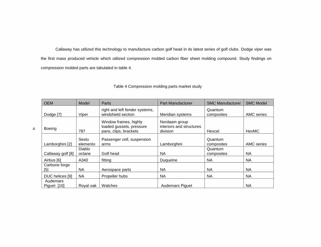
Callaway has utilized this technology to manufacture carbon golf head in its latest series of golf clubs. Dodge viper was
the first mass produced vehicle which utilized compression molded carbon fiber sheet molding compound. Study findings on
compression molded parts are tabulated in table 4.
Table 4 Compression molding parts market study
OEM Model Parts Part Manufacturer SMC Manufacturer SMC Model
Dodge [7] Viper right and left fender systems, windshield section Meridian systems
Quantum composites AMC series
Boeing 787
Window frames, highly loaded gussets, pressure pans, clips, brackets
Nordaam group interiors and structures division Hexcel HexMC
Lamborghini [2] Sesto elemento
Passenger cell, suspension arms Lamborghini
Quantum composites AMC series
Callaway golf [8] Diablo octane Golf head NA
Quantum composites NA
Airbus [6] A340 fitting Duqueine NA NA
Carbone forge [5] NA Aerospace parts NA NA NA
DUC helices [9] NA Propeller hubs NA NA NA
Audemars Piguet [10] Royal oak Watches Audemars Piguet NA
9

10
1.6.5 Challenges
Fiber orientation in the part determines the strength of the part. Fiber orientation is
decided by the material flow during mold closing. The quality of a compression molded part is
dependent on numerous factors unlike the other process. The challenges include good part
design, material selection, mold design, thermal system design, charge placement, process
parameters etc.
1.7 Objective of Thesis
This thesis will focus on developing a high strength part for the racing team using
compression molding process. The part development must lead to significant weight savings
and additional benefits to the team. Three key areas had been identified which significantly
affect the compression molding process. They are part geometry, raw material and process
conditions. The influencing parameters will be studied and the parameters will be identified for
the wheel center development.
1.8 Outline of the Thesis
Chapter 1 describes about composites and brief introduction to compression molding
process
Chapter 2 talks about identification of a high strength part and raw material for
compression molding
Chapter 3 explains the structural analysis of the existing design and the proposed
design.
Chapter 4 details about the mold design and process parameters identification and
prediction for the wheel center development
Chapter 5 summarizes the results and scope for future work

11
CHAPTER 2
IDENTIFICATION OF PART AND RAW MATERIAL SELECTION
2.1 Expectations from the part development
Formula Society of Automotive Engineers team (FSAE) is functioning in our university
which involves a group of students in building a formula style race car towards the yearly
competition. The team has won several times in the competitions because of the competitive
car built by the students. Weight reductions in parts play a vital role in deciding a championship.
The car should be extremely light but powerful. This paves the way for carbon composite
materials usage in the structures used in the car. Every year the formula SAE team is revising
its target goal in achieving the performance in order to stay competitive in the competition. This
part development process by using composite was aimed at benefitting the team’s performance.
Weight reduction will be the main goal of this development process without compromising
strength and other requirements. The alternate manufacturing method will ease the way in
which the part is manufactured today. The new process should address the following aspects
such as adaptability, cost, quality output parts and reduction of skilled labor requirement.
2.2 Part Identification
A part needs to be selected such that it reaps in maximum benefits from the
development. Aluminum and metal casting parts are the main focus here as they consume a lot
of weight in the car. Part selection must address the following criteria
1. Weight of the part and influence of weight reduction in target goal
2. Addressing existing functional issues
3. Reduction in manufacturing lead time

12
Some of the heavy weight parts are wheel center, wheel hub, control arms etc. Of these
based on the above set of criteria wheel center and wheel hub are identified for compression
molding process. The most suitable part will be selected based on existing process study,
weight reduction scope and effect.
2.2.1 Wheel center
Wheel center is a critical functional part which connects the wheel rim and the wheel
hub. It is a critical load bearing member which experiences high stress during cornering and
braking. Existing wheel center which is used by the team is shown in figure 5. Loads are
transmitted from the ground through the tire and to the wheel center. Identical wheel centers are
used for all four wheels. Each wheel center weighs around 1.98lb which makes 7.92lb for the
entire car. Wheel center is made of Al 6061 T6 material. It is manufactured by machining a solid
aluminum block.
Figure 5 Existing wheel center

13
The main constraints of the present wheel center are high machining time and high
material wastage as it is machined from a solid block. Present design has complicated profiles
in the form of a radial pattern. Every year the team manufactures two sets of wheel centers for
the competition. Each set consist of four wheel centers. Deflection in the part was found to be
high. For weight reduction the hollow spaces are created in between the patterns which give
rise to the stress concentrations in the arms. The component has not failed as of now in any
circumstances. Weight reductions, stiffness increase, reducing manufacturing lead time are the
key areas which are identified for the compression molding process. Wheel center is subjected
to racing driving conditions. It involves dry and wet track racing conditions. It is also subjected to
high temperatures. Heat generated in the tires will be dissipated through the wheel rims and to
the wheel center.
2.2.2 Wheel hub
Wheel hub is a structural load bearing member. Wheel hub connects the wheel center
and the stationery axle through bearings. Wheel hub is mounted to wheel center on one side
and it’s positioned over the stationery axle though two tapered roller bearings. Brake disc is
mounted to the wheel hub. It experiences severe load in the form of torsion when the disc
brakes are applied and also a considerable load from cornering which is transferred from the
wheel center. Wheel hub is made of Al 6061 T6 alloy. Wheel hub weighs at 0.98lb. Each car
utilizes two identical wheel hubs which sums the total weight of 1.96 lbs. Each year the team
manufactures two sets of wheel hubs for the competition use. Existing wheel hub which is used
by the team is shown in figure 6.

14
Figure 6 Wheel hub
It is manufactured by machining a solid block of aluminum. It involves numerous
machine setups because of the profile complexity in the part. The component is very rigid and
has high FOS. This component has not failed in the past since its inception. The areas where it
is mounted with brake disc and the wheel center are the high stressed areas. Wheel hub is
subjected to high temperatures. The heat generated from the brake disc is dissipated in the
wheel hub.
2.2.3 Comparison
The following criteria are considered before the selection
2.2.3.1 Influence of improvement in teams goal
Our target of 20% weight reduction will impact wheel center greatly than wheel hub.
Total weight reduction of 1.58 lbs can be achieved by wheel center against 0.392 lbs through
wheel hub. Each year the team revises the weight of the car to be 25 lbs lighter than the
previous year. With that goal into consideration the influence of weight reduction through wheel
center will be significant than the wheel hub.

15
2.2.3.2 Existing process study
Both the parts are manufactured by machining solid aluminum. The number of
machining setups is high in wheel hub when compared to wheel center. But the material
wastage will be higher in wheel center because of the part size. Wheel center is 10.5” in
diameter. Solid blocks of aluminum are required for machining. Wheel hub is 5” in diameter.
Either bars or solid blocks can be used because of the smaller size. Material wastage can be
greatly reduced in wheel center when compared to wheel hub.
2.2.3.3 Issues to be addressed
Wheel center has greater deflection under cornering. Wheel center bears less lateral
stiffness. On the other hand wheel hub has not got any significant issues to be addressed.
From the above comparison criteria wheel center will be the best suitable choice for
development through alternate process by composite.
2.3 Material selection
2.3.1 Raw material
Sheet molding compound (SMC), Bulk molding compound (BMC), Thick molding
compound (TMC) are the initial raw materials used for compression molding. Sheet molding
compound comes in the form of sheets of thickness ranging up to 0.236” whereas Thick
molding compound which is a thicker version of SMC has a thickness up to 2”. Bulk molding
compound comes in the form of logs or ropes which is extruded after mixing resin, fibers and
fillers and then cut to small lengths. Fiber content varies from 30% to 50%. Depending on the
fiber volume fraction the strength of the component is determined. Nowadays high strength raw
materials are being developed with fiber volumes greater than 50%.
All compounds utilized for compression molding process consists of 10% additives of
the total weight. Additives include initiators to start the chemical reaction, Inhibitors to retard the
reaction and low profile additives to control shrinkage.

16
2.3.2 Manufacturing
Sheet molding compound is prepared by dispersing chopped carbon fiber over resin
sheet and compacted after placing another resin sheet for impregnation. Fillers and curing
initiators are mixed with the resin to start curing. Curing starts once the resin wets out fibers
after compaction. Initiators such as heat activated peroxide will cause minimal curing in the
manufacturing stage. Furthermore to avoid premature curing it is stored in refrigerator under
sub zero conditions thereby extending the shelf life of the material. Typical shelf life of SMC
material will be in the order of 6 - 8 weeks when stored at room temperature 23 deg C. Normally
SMC requires a week to be used in compression molding from the time of sheet preparation.
This phase is called maturation phase.
2.3.3 Types
Sheet molding compound can be either
1. SMC-R for randomly oriented short fibers.
2. SMC-CR for continuously oriented fibers.
3. XMC represents mixture of short fibers and continuous fiber reinforcement.
2.3.4 Curing process
Curing of the material is directly related to the viscosity of the material. Viscosity of the
material is constantly changing throughout the lifecycle of SMC. During molding operation the
sheets are placed in the heated mold which causes the resin viscosity to decrease once it
absorbs the heat and starts flowing in the mold. Preheating of the charge outside the mold can
be done for quicker processing. Flow of the material is associated with the viscosity and that is
related to the fiber content and the resin compatibility with the fibers. Viscosity increases and
the curing reach a maximum. Too many fibers will reduce the flow and high viscosity will also
inhibit flow. The art lies in finding a balance with the fibers and causing the material to flow
along with the fibers. Minimal flow is a typical feature of SMC molding as the charge already
covers 80% of the mold during initial placement. The material is stored in rolls or stack form.

17
They should be used within a limited period as they have a limited shelf life. Various curing
models have been developed in order to define the complex curing process. Barone and Caulk
was the first who developed an analytical cure model for SMC [12].
2.4 SMC materials market study comparison
A raw material which is suitable for the compression molding process and also should
possess stiffness similar to existing aluminum 6061 T6 is required for our development.
Availability and usage of this compound in the industry is also considered.
A study was made on the list of available SMC in the market matching the properties of existing
grade. Hexcel, Quantum composites and Tencate are the most dominant manufacturers of
sheet molding compound in the market. Around 15 compounds in the market are taken into the
study. Compounds belong to epoxy, vinyl ester, unsaturated poly ester and phenolic resin
types. Epoxy and vinyl ester resins can be used in thick regions. Unsaturated polyester is the
most commonly used but molding thick regions will be an issue. Phenolic resins are used in
place of fire resistance. Thickness of the wheel center ranges up to 1” in certain areas. Epoxies
and vinyl esters will be suitable for the purpose. Common differences between epoxy and vinyl
ester are tabulated in table 5.
Table 5 Epoxy resin and vinyl ester resin comparison
Epoxy resin Vinyl ester resin
Excellent adhesion, good thermal stability, good mechanical properties
High chemical resistance
Expensive than vinyl ester Less expensive than epoxy but expensive than unsaturated polyester
Slow curing Fast curing
Most commonly used Only used in places of chemical resistance applications and corrosion requirements

18
Refer Appendix C for the detailed comparison of properties of all compounds taken for
the study. Properties of all the compounds are tabulated in table 15 and 16.
Hexcel [4]
HexMC is a proprietary sheet molding compound developed by Hexcel. It is one of the
high strength compounds available in the market. It is made of short fibers chopped from a
unidirectional prepreg. Each chopped fiber prepreg measures around 2” in length and 0.3” in
width. It has high shelf life time of 18 months. Cure time is relatively quicker than the others. It is
used in structures of Boeing, Lamborghini. Modulus value is slightly lower than aluminum but
the tensile strength equals aluminum values.
Quantum composites [7]
Lytex series and AMC series are the sheet molding compounds which are mainly used
in compression molding systems. Lytex is a carbon epoxy compound whereas AMC is carbon
vinyl ester compound. It is used in structures of Lamborghini. Complete properties of the
compound was not available to us.
Tencate YLA [13]
It is one of the fast curing intermediate modulus category compounds from Tencate.
Excellent moldability, good strength and stiffness are the key features. MS4A has almost equal
modulus values in all directions.
Properties of selected compounds are tabulated in table 6.

19
Table 6 SMC properties comparison
Manufacturer Aluminum[14] Hexcel Tencate
Properties/Material name
Al 6061 T6 HexMC® / C / 2000 /
M77 MS 1H MS 4A
Type - carbon epoxy
carbon epoxy
carbon epoxy
Material density lb/in3 0.098 0.056 0.055 0.054
Fiber length in - 2 1 1
Fiber width in 0.31 0.13 0.13
Fiber volume % - up to 57 52 52
Cure temp °f - 302 280-309 280-309
Tensile modulus msi 10 5.5 10 9
Compressive modulus msi
10 5.5 9 8
Flexural modulus msi 10 4.35 10 7
Press pressure psi - 725-2175 2000 2000
HexMC, MS4A, MS1H are the three compounds which are selected for the analysis
and based on the analysis results final compound will be chosen for the manufacture of wheel
center.

20
CHAPTER 3
ANALYSIS AND DESIGN OF EXISTING AND PROPOSED WHEEL CENTER
3.1 Software introduction
Software used for the analysis is Ansys 14 workbench. Static structural analysis is
performed for the wheel center. The components are modeled in solidworks and imported to
ansys and the analysis was performed as an assembly.
3.2 Analysis of existing design
3.2.1 Wheel center assembly
Wheel center is mounted to wheel hub on one side and wheel rim on the other. Wheel
hub is fastened to wheel center by four titanium lugs and nuts. On the other side, the flat face at
the periphery of the wheel center is butted on the wheel rim inside and riveted at the points
where the wheel center arms meet the rims. From the assembly the load transfer path is
predominantly in the rivet points which hold the components together. Wheel center assembly is
shown in figure 7.
Figure 7 Wheel center assembly

21
3.2.2 Loading conditions
Wheel center is subjected to two loading scenarios during the race. They are cornering
load and braking load conditions.
3.2.2.1 Cornering load
The car weight is supported on four tires touching the ground. These are the only
contact points with the ground. The vertical weight will push the tire towards the ground
whereas the lateral force acting towards the tire pushes the tire laterally. When the race car
approaches a turn the lateral load will act on the tires forcing the car out of the racing line.
Higher the speeds higher the cornering forces acting on the tires. During high speeds based on
the acceleration g’s the car weight is distributed between the tires. When the car is stationery
the car weight is equally loaded in the four tires but during motion the weight acting on the tire is
proportional to the acceleration g and also whether it is cornering or braking. During braking in
straight line, front tires will be loaded heavily and during cornering, the outside tires will be
loaded heavily. Forces acting on the wheel during cornering are shown in figure 8.
Figure 8 Cornering forces
The car is subjected to 3g acceleration at the maximum. The analysis should be done
for the extreme condition. During 3g acceleration in the corners the car will be subjected to 750
lb of lateral force and 600 lb of normal force (car weight). Diameter of the wheel center is 10.5 “.
22
3.2.2.2 Braking load condition
During braking the car will be subjected to 2g’s at the maximum and the force acting on
the wheel center is 600 lbs in addition to the car weight.
3.2.3 Analysis conditions
Wheel center is analyzed with wheel rim and wheel hub in place simulating the on track
conditions. The entire assembly models are obtained from the formula SAE team and analyzed
for the above load conditions. The car is loaded on four tires and only a small portion of the tire
which is really making contact with the ground. All the forces generated are transferred through
this small portion. A small contact patch was identified in the rim and the loads are applied. The
loads are given as remote forces from the point in the ground. The model is constrained in the
bearing seating faces of the hub. Bonded connection is used between the wheel rim and wheel
center and also between wheel center and hub. Stress and deformation in the part are our
prime interest in the analysis. Wheel center is also analyzed by rotating the wheel center in the
assembly by 45 deg. Results are found to be less than the normal assembly conditions. Hence
the analysis results of the normal condition is discussed and compared with the proposed
design. For other results refer Appendix D
3.2.4 Analysis results of the existing design
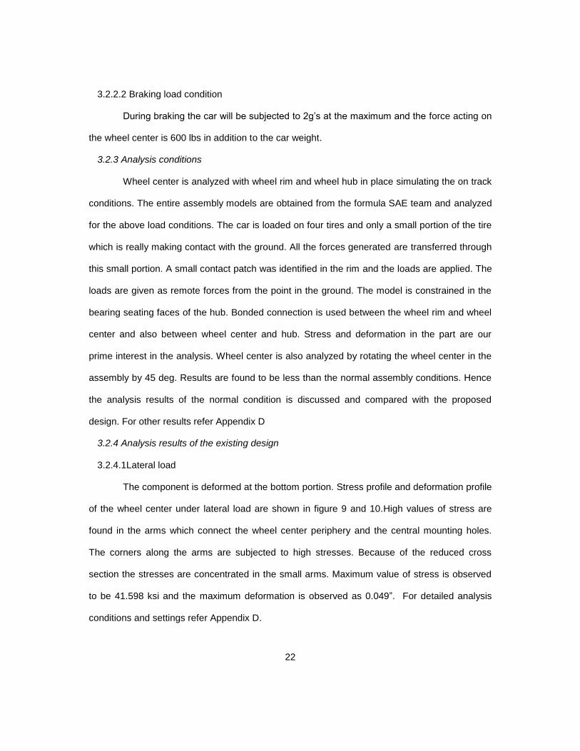
3.2.4.1Lateral load
The component is deformed at the bottom portion. Stress profile and deformation profile
of the wheel center under lateral load are shown in figure 9 and 10.High values of stress are
found in the arms which connect the wheel center periphery and the central mounting holes.
The corners along the arms are subjected to high stresses. Because of the reduced cross
section the stresses are concentrated in the small arms. Maximum value of stress is observed
to be 41.598 ksi and the maximum deformation is observed as 0.049”. For detailed analysis
conditions and settings refer Appendix D.

23
Figure 9 Stress plot in lateral load condition for existing wheel center
Figure 10 Deformation plot in lateral load condition for existing wheel center

24
3.2.4.2 Braking load
High stresses are found at the bottom radius of the arms. Peak value is found to be
9.034 ksi and the maximum deformation is found to be 0.0044808”. Stress plot and deformation
plot under braking load are shown in figure 11 and 12.
Figure 11 Stress plot under braking load in existing wheel center
Figure 12 Deformation plot under braking load in existing wheel center

25
3.2.4.3 Result interpretation
The component needs to be strengthened for the lateral stiffness. Arms which connect
the wheel center radially are the weakest points in the model. These areas should be
strengthened. High stress points are found in the arms in both the scenarios. High stressed
areas in wheel center are shown in figure 13.
Figure 13 High stress areas in wheel center
3.3 Proposed design
The periphery of the wheel center is thin and it is connected by arms to the center.
When the lateral load acts on the bottom edge of the wheel center it immediately bends
because of the lack of rigidity. It is not supported by a solid section. The loading regions must
be strengthened by adding material in these areas. The critical dimension for the proposed
dimension is shown in figure 14.
Figure 14 Stiffness increase section

26
Empty spaces between the patterns are not advisable. Compression molding process
requires the part to have a minimum draft angle of 1.5 deg in the direction of pull. Thickness
variation should be gradual. We cannot use a single charge to create the part at the present
condition. We need to place multiple charges in the mold all along the arms and the center
areas to process the part. The problem with using multiple charges is that the flow front of two
charges will meet creating a low strength area. We have too many spaces and we are inviting
too many flow front joining areas with the existing design. Instead we can use reduced
thickness in these regions or create mash off regions which will be removed once the part is
molded.
Figure 15 Proposed wheel center
Various design patterns are considered and analyzed for the stress values in the part
for lateral load conditions. Above design was finalized because of the ease of simplicity in
manufacturing and wider areas at the rivet intersection to provide better load transfer. Front and
rear view of the proposed design is shown in figure 15.
3.4 Analysis of proposed design
Similar loading and analysis conditions are used for the proposed design analysis too.
Proposed design promised over 20 % reduction in stress, deformation and weight than the
current design. The results are shown in figures 16 - 19. Proposed design reduces the part

27
weight by 24 %. It saves 1.84 lbs for the whole car. All three raw materials are analyzed for the
lateral load condition and the results are tabulated in table 7. Lateral stiffness of the component
is the prime deciding factor for the selection of raw material. Based on the values MS4A has got
the minimum deformation in the part under the analysis. Selected MS4A raw material behaves
in an isotropic fashion and hence isotropic properties are considered for analysis. Comparisons
between the existing and proposed wheel center are shown in figure 20-22.
Table 7 Raw material comparison
Material Stress (ksi) Deformation (in)
MS1H 32.177 0.036
MS4A 30.452 0.0358
HexMC 25.112 0.045
Figure 16 Stress plot for lateral load condition in proposed wheel center

28
Figure 17 Deformation plot for lateral load condition in proposed wheel center
Figure 18 Stress plot for braking load in proposed wheel center

29
Figure 19 Deformation plot for braking load in proposed wheel center
Figure 20 Wheel center stress comparison
41.60
9.03
30.452
3.958
0.00
15.00
30.00
45.00
Lateral load Braking
Existing
Proposed
WHEEL CENTER STRESS ANALYSIS COMPARISON (ksi)

30
Figure 21 Wheel center deformation comparison
Figure 22 Wheel center weight comparison
0.049
0.004
0.036
0.005
0.00
0.02
0.04
0.06
Lateral load Braking
Existing
Proposed
WHEEL CENTER DEFORMATION COMPARISON (in)
1.98
1.52
0.00
0.50
1.00
1.50
2.00
2.50
Existing Proposed
WHEEL CENTER WEIGHT COMPARISON (lbs)

31
3.5 Alternate design proposals
The mash off regions can be removed by additional machining operation. It will lead to
reduce further weight at the expense of increased deformation values. Proposed design B is
shown in figure 23 and the deformation plot for proposed design B in figure 24.
Figure 23 Proposed design B
Figure 24 Deformation plot under lateral load in proposed design B

32
The analysis results and weight comparison of existing and the proposed designs are
summarized in table 8-10. With additional weight reduction the percentage deformation
reduction decreases.
Table 8 Stress comparison
Stress (ksi) Lateral load Braking % reduction Lateral load
FOS Lateral
load
Existing 41.598 9.034 - 0.96
Proposed 1 30.452 3.958 27% 1.48
Proposed 2 27.709 7.627 33% 1.62
Table 9 Deformation comparison
Deformation (in) Lateral load Braking
% reduction Lateral load
Existing 0.049 0.00448
Proposed 1 0.0345 0.00447 30%
Proposed 2 0.0418 0.00603 15%
Table 10 Weight comparison
Weight (lb) % reduction
Existing 1.98
Proposed 1 1.52 24%
Proposed 2 1.28 36%
33
CHAPTER 4
MOLD DESIGN AND PROCESS PARAMETERS IDENTIFICATION
Deriving process conditions for a defect free part is a skill which comes out by
experience. Process conditions will be fine tuned each and every day until the desired quality is
achieved. Compression molding process depends on various process conditions which need to
be understood to get a desired part out of the process. Various influencing parameters are
studied and configurations are finalized in accordance to our wheel center development.
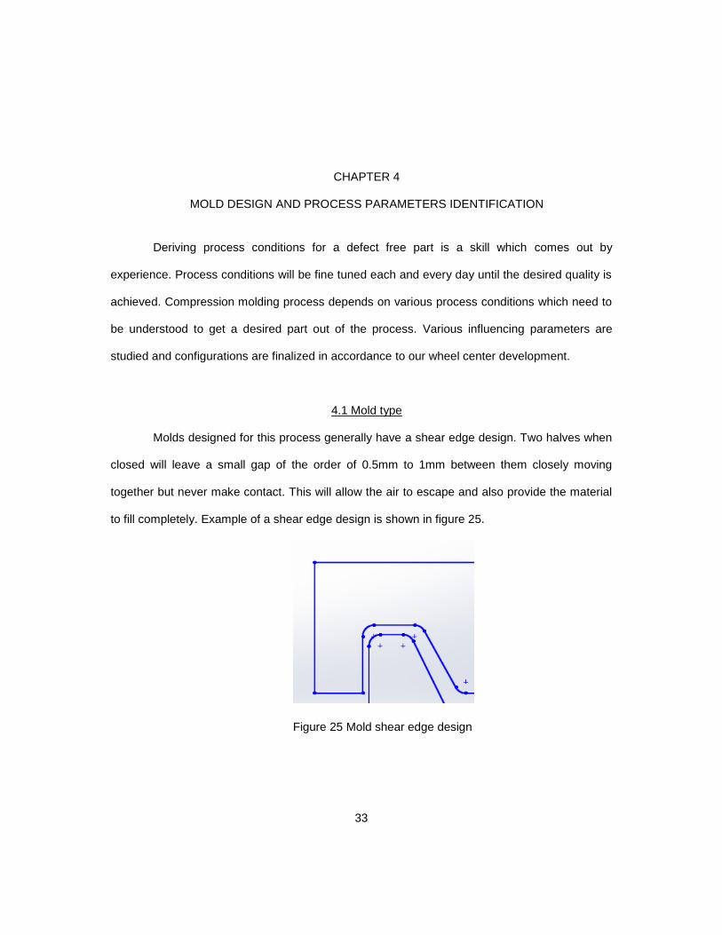
4.1 Mold type
Molds designed for this process generally have a shear edge design. Two halves when
closed will leave a small gap of the order of 0.5mm to 1mm between them closely moving
together but never make contact. This will allow the air to escape and also provide the material
to fill completely. Example of a shear edge design is shown in figure 25.
Figure 25 Mold shear edge design

34
4.2 Mold material
Compression molding process usually involves steel dies because of the large press
pressures involved. Molds are internally heated by heating sources. Steel conducts heat at a
lower rate. Nowadays aluminum molds are used for the process. The advantages of using
aluminum are reduction in machining time of the mold, superior surface finish, less maintenance
of the mold, free from corrosion and better heat transfer. Commonly used mold materials are
P20 steel, S7 steel, Al QC7 aluminum and Al7075 aerospace grade aluminum. Comparison of
the properties in terms of machining capabilities and thermal properties are tabulated in table
11.
Table 11 Mold materials properties comparison [15]
Mold materials P20 Al QC 7 S7 Al 7075 T6
Features
Common mold steel with good
fatigue abrasion and
impact resistance
Developed for molds
with higher strength,
hardness and conductivity
Excellent toughness and high strength
but lower wear
resistance
High strength and corrosion
resistance aircraft grade
Ultimate strength (ksi) 130 75 210 81.95
Modulus (msi) 29.73 10.5 30.02 10.5
Hardness Brinell 300 167 369 150
Cutting speed (ft/sec) 3.463 21.50 3.55 21.50
Volume machine rate (ft 3/h) 0.035 0.321 0.035 0.321
Thermal conductivity BTU ft/hr/ft2/deg F 20 91 21 75.1
Specific heat (BTU/ lb deg F) 0.119 0.206 0.110 0.229
Density (lb/in3) 0.283 0.101 0.282 0.102
Wheel center measures 10.5” in diameter. The mold size should be 15” in length and
14” in breadth and 2.5” thick. Aluminum is the preferred choice of the mold. Aluminum 6061 T6
grade alloy can be used for making the mold as the team gets the alloy through its sponsors.

35
Aluminum 6061 T6 is a heat treated aluminum alloy which stands next to Al 7075 in terms of
strength.
4.3 Press pressure, Process temperature
Fiber content determines the mold closing force. Higher the fiber content, larger the
force. Increase in fiber size also increases the mold closing force. The material should be
squeezed and forced to flow inside the cavity. Large pressures are involved for doing this.
During squeezing the entrapped air is forced out and leads to less void content in the part. Raw
material selected for our process is MS 4A which is manufactured by Tencate YLA. They had
fixed recommended curing pressure and temperature for this material to be followed to get a
desired quality part. Recommended pressure for curing a MS 4A part is 2000 psi at 302 deg F
[13].
4.4 Mold temperature
The mold is heated by a heating source which maintains a uniform temperature
distribution in the mold. The charge absorbs heat from the mold and starts curing (resin starts
flowing in the mold as the viscosity drops). Any variation in the temperature within the cavity will
affect the part curing levels within the part. Certain areas will be fully cured and the other areas
will be partially cured. Maintaining the temperature uniformly depends on heating system and
temperature controllers. Thermocouples will be placed in the mold at desired areas where the
temperature profile is highly important. The feedback signals from the thermocouples are fed
back to the temperature controller and the controller adjusts the heater sources accordingly by
switching it on and off based on the set point temperature.
4.4.1 Heating system
Heating system is embedded in the mold or sometimes in the platen which is attached
to the press. Mold can be heated by a variety of sources. Oil, electric, water heating systems
are available. Oil heating system and water heating system produces uniform temperature
distribution in the mold but the capital investment is high and the maintenance is also high. On

36
the other hand electric heating systems are low cost, less maintenance and easy to manage;
the temperature distribution is not so uniform like oil heating system. But with the individual
temperature controllers available today the heaters are controlled in zones splitted in the mold
so that the change in temperature is kept less than 5 deg C (41deg F). Electric heaters will be
the most feasible and economic option in terms of cost, maintenance etc. A study was made on
the available electric heaters and their configuration availability in the market. For the detailed
study refer Appendix F. Cartridge heaters was selected for the purpose among the various
heaters available in the market. Cartridge heaters are cylindrical rod like heaters. Cartridge
heaters are available under various lengths and watt densities. They are easy to place in the
mold and heats up quickly.
Figure 26 Cartridge heaters [16]
It can be easily replaced in case of failure. It will provide uniform heating throughout the
body. For deciding the wattage required per heater for heating the mold we need to calculate
the heat required for the mold and charge to reach the processing temperature.
4.4.1.1 Wattage calculation
Mold is made of Al 6061 T6 alloy. Specific heat capacity and density are listed
in the table. Heat capacity required for heating the mold is calculated and found to be 2.82 KW
in 30 minutes without losses. Wattage required for charge material to be heated was found to
be 0.09 KW without losses. Wattage calculations are tabulated in tables 12-14.

37
Table 12 Heat capacity required for heating the mold without losses
MOLD
Mold material Al 6061 T6
Material density lb/in3 0.098
Specific heat 0.214
No of halves 2
Mold length in 15
Mold breadth in 14
Mold thickness in 2.5
Volume in3 525
Volume of the cavity (part profile) in3 28
Net volume in3 497.00
Mass /half lb 48.46
Total mass lb 96.92
Operating temperature 302
Ambient temperature 70
time required to heat up hr 0.5
Wattage required for heat up KW 2.82
Table 13 Heat capacity required for heating the charge
CHARGE MATERIAL
Type MS 4A
Mass lb 1.51
Operating temperature 302
Ambient temperature 70
time required to heat up hr 0.32
Wattage required for heatup KW 0.09
Total wattage without heat losses
Total wattage (A+C) KW 2.91
Compensation factor 10% 0.29
Total wattage required KW 3.20
Heat loss graphs are referred from a manufacturer’s website [16]. Refer Appendix F for
the graph. Heat loss from the side walls of the mold and from the top surface is included.
Wattage lost due to convection heat loss is found to be 0.41 KW.

38
Table 14 Net heat capacity required after losses
Heat loss Mold
Vertical surface area (four sides) in2 290
Heat loss from vertical surface at 150 deg c W/ft2 75
Heat loss from mold vertical surface KW 0.15
Horizontal surface area top and bottom in2 420
Heat loss from horizontal surface surface at 150 deg c W/ft2 75
Heat loss from platen horizontal surface KW 0.22
Total KW 0.37
Compensation 10% 0.04
Total wattage losses KW 0.41
Total wattage required after heat losses KW 3.61
W 3600
A total of 3600 W is required for heating up the mold along with the charge. Cartridge
heaters of 12” in length and 0.5” in diameter will be used. Maximum of 8 heaters or 4 per mold
can be used with the available mold space. Wattage required per heater is 450W. Watt density
per heater is 23.88 W/in2. Commercial available heaters come in variety of sizes and watt
densities. Heater fittings can be screw mounted, NPT, L bend etc. The leads coming out of the
heater has a number of options. Thermocouple can be embedded in the heater too. For our
process 8 cartridge heaters of 450 W heat capacity and measuring 12” length 0.5” diameter with
screw mounting and normal lead is selected.
4.4.1.2 Thermal simulation for heating system
Temperature distribution in the mold is an important consideration for curing of the part.
Heaters are assembled in the mold which is designed from the proposed wheel center and
analyzed for the temperature distribution in the cavity. SS 304 material is used for heaters and
Al 6061 T6 for mold and each heater capacity used is 450W.

39
Figure 27 Top mold thermal distribution
Figure 28 Bottom mold thermal distribution
Convection load is applied to the top and two sides in which the heaters are mounted. Static
thermal analysis was done in Ansys. Maximum temperature variation of up to 10 deg C was
found in the mold after 30 min. Thermal profiles for top and bottom molds are shown in figures

40
27-28. Initial charge covers up to 80% of the mold. They absorb the initial heat. Temperature
uniformity in the mold coverage area is important rather than maintaining it for the entire cavity.
4.4.2 Cooling system
Charge curing involves two phases namely absorption of heat and liberation of heat
during cross linking. Heating system provides the heat for absorption in order to reduce
viscosity and start flowing. The heat liberated during the curing process is absorbed by the
cooling channels which run in the mold which is placed in alternate fashion to the heaters.
Unusual cooling will result in component warpage. Warpage is a critical issue in compression
molding. Non- uniform temperature profiles will result in warping. Cooling system can be water
cooled, oil cooled or by heat pipes. Oil heating system and water heating system can be
reversed to cool the mold thus providing both the functions but requires machinery investment.
Our process will include water cooled system. It will be circulated by water pressure which is
connected to the normal water line. The outlet water will be fed to the drains. Cooling channels
are made in the mold which circulates just like radiator design and the outlet water comes from
the other side of the mold extracting heat from the mold. Cooling channels positions are
analyzed to visualize the time required for the mold to cool from 150 deg C which is the curing
temperature stated by the manufacturer. Molds are analyzed for various flow rates ranging from
0.5m/s to 3 m/s with increments of 0.5. It was observed that the time required varies between
the top and bottom mold for a constant flow rate.

41
Figure 29 Top mold temperature variation with flow rate
In order to find a similar cooling curve for both the molds various flow rates are
analyzed separately and the curves are plotted in figures 29-31. The closest curve between the
top and bottom mold will yield an identical cooling between the top and bottom halves.
Figure 30 Bottom mold temperature variation with flow rate
0
40
80
120
160
0 200 400 600
Tem
pe
ratu
re d
eg
C
Time sec
Top mold temperature vs time
T 2.5 m/s
T2 m/s
T1.5 m/s
T1 m/s
T0.5 m/s
0
40
80
120
160
0 200 400 600 800
Tem
pe
ratu
re d
eg
C
Time sec
Bottom mold temperature vs time
B3 m/s
B 2.5 m/s
B2 m/s
B1.5 m/s
B1 m/s
B0.5 m/s

42
Figure 31 Mold temperature top and bottom
4.5 Mold Construction
The heating and cooling system in both the molds are analyzed for their position to
produce effective heating and cooling uniformly in the mold. Guide pillars are assmebled in the
top mold before clamping it in the press.The mold is clamped to the base plate or platen in the
press through T slots and screws. The threaded couplings are fitted to the mold and then the
heaters are placed. Bore size of the heaters is an important parameters to be achieved in
machining of the mold. Gap between the heater and the bore determines the heat transfer.
Close gaps of the order of 0.02 mm to be manintained. The top mold slides through the guide
pillar and mates with the bottom mold ensuring a closed cavity. Parallelism of the molds is very
important in ensuring uniform pressure application over the cavity and also the flash formation.
Part ejection is done by the ejector pin arrangement provided in the bottom mold.
Ejector pins are placed in four locations. They can be activated by a pneumatic system.
Tonnage required for the process was found to be 85T with the proejcted area of 85 in2 and
press pressure of 2000psi. Recommended press parallelism is 0.001”/ft. Mold assmebly and
exploded view of the top and bottom molds are shown in figures 32-35.
0
40
80
120
160
0 200 400 600
Tem
pe
ratu
re d
eg
c
Time sec
Mold temperature Bottom vs Top
T0.5 m/s
B 2.5 m/s

43
Figure 32 Top mold
Figure 33 Bottom mold

44
Figure 34 Mold exploded view
Figure 35 Mold assembled view

45
4.6 Press closing speed
Closing speed of the mold will affect the flow of the material. When the material gets
heated up it softens (i.e., viscosity drops) and starts flowing in the cavity. At this point of time the
mold should be closed as soon as possible. Flashes in the mold are controlled by the mold
closing speed. Closing speed can be finalized by using trial and error method during process
trials or using simulation.
4.7 Charge pattern
Charge pattern plays an important role in determining the properties in each section of
the part. Sheet molding compounds also called as charge is placed in the mold. A single sheet
cannot facilitate for the entire mold. Sheets should be cut and strategically placed in order to
avoid knit lines (place where flow of two sheets meet) when they are cured. This will lead to less
strength in that area. The knit lines should be predicted based on the charge pattern and should
be offset to non critical areas as they cannot be avoided completely. Charge usually covers
around 80% of the mold.
4.8 Process simulation study
Process simulation will help us understand the compression molding process better
which will lead to better part design, mold design and process design. The cost incurred for
preparing the mold is high because of the heating and cooling system requirements in the mold.
Hence a process simulation will help us reduce costs greatly in mold design. Temperature
distribution in the mold can be simulated and with respect to the temperature the curing of the
charge varies in the mold. The flow characteristics of the charge depend on the part design,
mold design, temperature distribution. The fibers will tend to flow during the cure along with the
resin and it will be cured once it fills the cavity. The fiber orientation will be a critical parameter
to be tested and that is done effortlessly by the process simulation. Fiber orientation model was
developed by Folgar-Tucker [12 ]. Based on the fiber intensity the strength can be calculated

46
and the structural analysis can be done based on the fiber orientations. Charge placement is
another important aspect that requires a lot of trials to be decided when we manufacture the
part. The trials can be done to simulate the effective filling and the optimum charge placement
can be found. These are some of the advantages of the software process simulation.
4.9 Software
Compression molding process simulation is relatively new to industry. There are not too
many players in the simulation industry market. Few software’s are developed for the consulting
purpose or for private use.
Cadpress (Madison group) [17]
Express (M Base) [18]
Passage (Technalysis) – Commercial version available [19]
Moldflow (Autodesk) [20]
Moldex3d – Commercial version launched in Mar 2013 [21]

47
CHAPTER 5
CONCLUSIONS AND FUTURE WORK
Three key areas influencing the compression molding process are studied and the
systems are designed and process conditions are predicted through the wheel center part
development. With the mold design and the associated systems in place manufacturing of the
part can take place. The next step in the development is manufacturing and testing of the part.
Some of defects which might be encountered during manufacturing are blisters, chipped edges,
drag marks, fiber pull, flow lines etc. These defects can be avoided by close control in the
process parameters. Troubleshooting of compression molding process for various defects which
are found during the process was explained in detail by Davis [12].
In future the process simulation will play a key role in designing the part and mold. In
future part developments by compression molding process, process simulation in addition to
structural analysis can be done to evaluate the process variables.

48
APPENDIX A
LITERATURE REVIEW

49
Importance of composite parts and development of a carbon/epoxy structural part for a
high performance vehicle was studied by Feraboli [22]. Fiber architecture, Failure modes,
factors affecting strength are discussed in this paper. A fiber reinforced thermoset part
development (engine valve cover) which is used in Daimler Chrysler 4.7L V8 engine was
studied by Steve Crawford [23]. The development process and the importance of FEM
simulation in the analysis of the part and process are explained. Flow simulation was done to
simulate the mold filling to optimize the process.
Modulus measurement for prepreg based discontinuous fibers was studied by Paolo
Feraboli [24]. Notched behavior for a discontinuous carbon fiber/epoxy system was done by
Paolo Feraboli [25]. The elastic behavior and the failure response are studied. Comparison is
made between a notched specimen and an unnotched specimen. Short fibers are notch
insensitive is the key finding in this research study. Failure initiation in HexMC molded panels
and the effect of defects was studied by Bruno Boursier [26]. The differences in failure initiation
in both discontinuous and continuous fiber composites were discussed. Characteristics and
influence of strength with respect to various attributes are studied by Paolo Feraboli [27]. The
relationship between aspect ratio and tensile, compressive and flexural moduli and strengths
are observed. Failure in these materials is mainly dominated by matrix rather than fibers were a
key finding in this study.
A method of finding modulus value in discontinuous fiber molded panels was proposed
by Paolo Feraboli [28]. Large modulus variations are observed in short fibers molded panels
due to the heterogeneous nature of the material. In order to evaluate the modulus value of
these types of panels a randomization process called Random Representative Volume Element
(RRVE) algorithm was developed.
Forged composite technology which was demonstrated in Lamborghini and Callaway
was discussed by Paolo Feraboli [29]. Development of control arms with discontinuous fibers
was discussed. Design methodology, FEM analysis comparison, Material selection was

50
discussed and compared with the current manufacturing process by Aluminum.
Characterization and the mechanical properties of Callaway forged carbon fiber reinforced
sheet molding compound was studied by Bradley Jones [30]. Panels were prepared and tensile
strength, flexure strength values are measured and the variations are recorded for the test
panel.
Molding parameters such as mold closing speed and mold temperature are studied for
their effect in tensile and flexural properties by Ki-Taek Kim [31]. Surface roughness, tensile and
three point bending tests were conducted on the molded parts. Fiber orientation and distribution
in the molded parts were also investigated in this study.
Analysis and certification of discontinuous carbon fiber reinforced composite is difficult because
it does not behave like unidirectional composites or isotropic materials. Panels made of HexMC
are molded and the effects of material flow and material behavior are studied by Mark Tuttle
[32]. The panels are tested for tensile strength and the results were discussed.
Manufacturing a part by various processes and by various available materials that is
available for composites processing and the costs involved are compared by Michael G Bader
[33]. Importance of computer aided engineering CAE in compression molding process
simulation was demonstrated by Antoine Rios [34]. The effect of flow pattern, temperature and
curing will affect the properties of the part. Warpage simulation, residual stress analysis is done
in order to optimize the design at the development stage. The mechanism by which the sink
marks occur in the compression molded parts are studied by Tsuneo Hirai [35] and methods to
minimize the sink mark formation is developed.
Reasons for poor surface quality in compression molded parts was studied and the
parameters was found and parameterized compression molding process was performed with
Design of Experiments approach to find the influence of the parameters in the surface quality of
the parts by N E Jimmy Olsson [36].

51
Dodge viper demonstrated the usage of carbon fiber SMC in large volume for the first
time. Carbon fiber SMC is used in right and left fender systems and for stiffening in windshield
support along with fiber glass SMC. Development process of the carbon composite molded
parts was studied by Mark Bruderick [37].
Numerical simulation of the compression molding process was compared with a
simulation of a thermoset sample by Sejin Han [38]. Comparison results include flow pattern,
fiber orientation, fiber length distribution and curing of the resin. Comparison yields reasonable
agreement between the experiment and simulation.
Importance of chopped prepregs was studied by jack D Fudge [39]. Characteristics,
advantages of chopped prepregs in comparison with normal unidirectional prepreg and
aluminum is included and validated for the cost impact between them. Effect of reinforcement
type and length in the properties of the part was studied by Sarah Boylan [41]. Comparison
include usage of various sizes of glass fibers and carbon fibers and the effect on properties and
surface quality of the molded part.
The essential guidelines for a high volume compression molded carbon epoxy part was
studied by Donald M. Lasell [42].

52
APPENDIX B
THERMOSET MANUFACTURING PROCESSES REVIEW

53
Thermoset composites are more rigid and suitable for high strength applications than
thermoplastic composites. Thermoset composites occupy a major portion of the composite
market. They comprise around 75% of the total composite market. Processes used for
thermoset composites are more established and it’s used in variety of industries. Thermoset
composites are used in aerospace, automotive, sporting and commercial applications. We are
limiting our study on the various manufacturing methods available for thermoset composites.
Prepreg layup process
Process description: Prepreg layup is a type of hand layup process. Prepreg sheets are nothing
but resin impregnated sheets. Process sequence include placing the prepreg sheets in the mold
in desired pattern to achieve desired fiber orientation, vacuum bag the entire mold setup, place
the setup in the autoclave under monitored pressure and temperature.
Process parameter: Labor skill
Advantages: High fiber volume fraction can be achieved, minimum tooling requirement and
suitable for low volume industries.
Applications: Big parts used for aircraft structures are primarily manufactured by prepreg layup
because of the high fiber volume fraction requirement which is related to the strength.
Applications include large aircraft structures, yachts and sporting goods.
Challenge: achieving desired orientation, maintaining low void content.
Disadvantages: high lead time, labor intensive process.
Wet layup process
Process description: It is a hand layup process. Curing is done under normal room temperature.
Resin is applied to the mold and then the reinforcements are added over to the mold and
compacted by a roller until it is impregnated by a resin. This process is repeated until the
desired thickness is achieved.

54
Process parameters: Operator skill
Advantages: simplicity and less expensive.
Applications: manufacture of boats, yachts in the marine industry.
Challenges: achieving part consistency, fiber volume fraction control
Disadvantages: High labor skill dependency, low productivity, High styrene emission
Spray layup process
Process description: Spray layup process differs from wet layup process in the method of
application of fibers and resin over the mold. An air gun is used which is fed with continuous
roving’s of fibers and the fibers are chopped and immersed in the resin and sprayed over the
mold. Chopping and impregnation with resin is done in the spray gun. Compaction to remove air
bubbles is done by rollers.
Process parameters: Operator skill and spray pattern.
Advantages: less expensive, relatively simple process, suitable for low volume and large non
structural items.
Applications: Bathtubs, storage tanks, swimming pools
Challenges: Achieving uniform density of fiber is difficult.
Disadvantages: Suitable for low volume and non structural applications.
Filament winding process
Process description: Filament winding process is suitable for producing tubular structures.
Continuous roving’s of fibers are wound over rotating mandrel after immersing the fiber over
resin. By adjusting the motion of tail stock and rotational speed of mandrel the desired fiber
orientation angle is achieved. Curing can be done at room temperature and also under heated
ovens. Filament winding process is the only available process for making pressure vessels.
Tooling cost is less and the mandrels used are relatively inexpensive.

55
Process parameters: Motion of tailstock, speed of mandrel and fiber tension
Advantages: Use of cheap raw material such as fiber roving’s, high volume production, desires
fiber angle can be achieved by CAM control, independent of operator skill
Applications: Tubes, fishing rods, golf equipments, pressure vessel
Challenges: Achieving small fiber angles, controlling the fiber volume fraction.
Disadvantages: Limited to only tubular structures, Investment in the form of machinery and
automated software for controlling the fiber orientations are required
Pultrusion Process
Process description: Pultrusion process is mainly suitable to produce constant cross section
parts. Roving’s of fibers are immersed in a resin bath and pulled through a steel die with the
impression of the final part shape. Curing is almost done when the part comes out of the die as
the dies are heated.
Process parameters: Resin impregnation, Steel dies heating, Part shape
Advantages: High volume production, can be automated, utilization of cheap raw material such
as fiber rovings
Applications: constant cross section parts such as channels, bars etc
Challenges: Achieving fiber angle.
Disadvantages: Suitable for only constant cross section, High tolerances cannot be achieved,
surface texture is not smooth, thin walled parts cannot be processed
Resin Transfer Molding
Process description: Resin transfer molding is suitable for manufacturing high strength parts at
moderate volumes. Process includes layup of a preform in the mold and then the mold is closed
and the resin is forced into mold under pressure to wet out the fabric. The resin impregnates the
fabric and starts curing. After certain period of time depending on the part geometry the mold is

56
opened to take out the part. Preform can be conformal mats, or fabric. Tooling is inexpensive
when compared to injection and compression molding.
Process parameters: Resin infusion
Advantages: High strength parts can be made, suitable for moderate volumes, less expensive
tooling as the processing pressure is low, better surface finish as the mold is closed and High
tolerances can be achieved
Applications: bicycle frames, windmill blades, sports car bodies, automotive panels
Challenges: achieving uniform resin infusion, avoiding dry areas
Disadvantages: Good knowledge about resin transfer is required which includes simulation
model of the resin infusion, tooling expensive than hand layup process
Structural reaction Injection molding
Process description: This process is derived from RTM. The main difference is the method of
application of resin. In this method the two resins are forced to mix at high velocity and pressure
on a separate chamber and the mixed resins are forced into the mold at low pressure. A
preform is already placed in the mold which is made of short fibers. The resin impregnates the
preform and the curing starts. The cross linking is quick in this process as the resin is allowed to
mix at high pressures.
Process parameters: resin mixing and injection into the mold
Advantages: High volume production, high strength parts can be made, automated process for
better results
Applications: Used in automotive industry where high volume and low cycle time are required.
Challenges: Fibers wash away while resin is injected
Disadvantages: Requires large investment in the form of tools, high fiber volume fraction cannot
be achieved.

57
Compression molding
Process description: Sheet molding compounds are cut to defined shapes and placed in a
heated mold. The mold is closed and the material is allowed to flow in the cavity, because of the
viscosity drop by the absorption of heat from the mold. Once the curing is done the mold is
unclamped and the part is removed. Steel tools are used because of the high pressures
involved in the process.
Process parameters: Mold filling, mold temperature, mold closing speed, pressure, charge
placement
Advantages: High volume production, less labor dependency, high intricate shapes can be
produced, good dimensional tolerance
Applications: panels, spoilers, doors hoods
Challenges: mold filling
Disadvantages: High initial investment in the form of tooling, high strength parts cannot be
made, reinforcements required.
Roll wrapping
Process description: It is similar to prepreg layup but the prepreg mats are rolled over by
mandrels and a shrink wrap is made and it is allowed to cure. Once the curing is completed the
mandrel can be withdrawn and the part is taken out. It is suitable for producing cylindrical tubes.
Tooling is inexpensive.
Process parameters: Operator skill in rolling the mandrel with uniform pressure and squeezing
the entrapped air
Advantages: high volume production, less expensive tooling, high fiber volume fraction, highly
suitable for thin and tapered cross sections
Applications: golf shafts, fishing rods
Challenges: reducing voids, surface quality
Disadvantages: Limited to tubular structures and thick composite parts cannot be made

58
Injection Molding
Process description: Injection molding is one of the most commonly used process in the
industry because of its advantages and productivity. Bulk molding compound is used as raw
material which is available in the form of pellets. Pellets are loaded in a hopper and it is
propelled through a chamber by a rotating screw. The injection chamber is heated so that the
mixture viscosity is reduced before injecting it into mold. Then it is injected to the mold at high
speed by a plunger. Because of the high processing pressures high strength tools are required
Process parameters: plunger speed, temperature of the feed chamber, Mold closing pressure
Advantages: high volume production, good dimensional stability,
Applications: small appliances, motor housings, electrical fuses
Challenges: mold flow design
Disadvantages: High investment in tooling, fiber breakage during injection

Figure 36 Manufacturing process selection criteria [1]
59

60
APPENDIX C
SHEET MOLDING COMPOUND

Table 15 SMC study comparison [6,7]
Manufacturer Hexcel Quantum Composites
Properties/Material name
HexMC® / C / 2000
/ M77
AMC8590 HT
AMC 8590
AMC8592 AMC8593 AMC8593
HT Lytex 4149
Lytex 4181
Lytex 4197
Type carbon epoxy
carbon vinyl ester
carbon vinyl ester
carbon vinyl ester
carbon vinyl ester
carbon vinyl ester
carbon epoxy
carbon epoxy
carbon epoxy
Material Density lb/in
3
0.056 0.053 0.053 0.053 0.053 0.052 0.053 0.053 0.053
Fiber Length in 2 1 1 2 1 1 1 1 2
fiber width in 0.31 NA NA NA NA NA NA NA NA
Fiber Volume % Up to 57 53 53 53 50 50 55 55 55
Cure temp °F 302 259-309 259-309
259-309 259-309 259-309 280-329
280-329
280-329
Cure time min 3 5 to 10 5 to 10 5 to 10 5 to 10 5 to 10 5 to 10 5 to 10 5 to 10
Tensile strength ksi 44 40 40 55 61 40 42 25 42
Tensile modulus msi 38 10 9 10 9.5 10 8 7.8 11
Compression strength ksi
42 NA NA NA NA NA 40 0 0
Compressive modulus msi
38 NA NA NA NA NA 4.6 NA NA
Flexural strength Ksi 73 82 90 92 115 82 89 70 107
Flexural modulus msi 30 5.9 5.2 4.7 6.5 6.2 5 5.5 7.2
Shelf life at room temp weeks
6 8 8 8 8 8 NA NA NA
Shelf life at 0 °F 18
months NA NA NA NA NA
6 months
6 months
6 months
Press pressure psi 725-2175 NA NA NA NA NA NA NA NA
NA - Data not available
61

Table 16 SMC study [8]
Manufacturer Tencate
Properties/Material name MS 1A MS 1D MS 1H MS 2D MS 4A MS 4H MS 4F
Type carbon epoxy
carbon epoxy
carbon epoxy
carbon epoxy
carbon epoxy
carbon epoxy
carbon cyanate
ester
Material Density lb/in3 0.056 0.062 0.055 0.061 0.054 0.055 0.054
Fiber Length in 1 25 1 25 1 1 1
fiber width in 0.13 NA 0.13 0.13 0.13 0.13 0.13
Fiber Volume % 52 52 52 52 52 52 52
Cure temp °F 280-309 138 -154 280-309 138 -154 280-309 280-309 325-365
Cure time min 30 30 30 30 30 30 50
Tensile strength ksi 42 28 37 28 45 44 45
Tensile modulus msi 19 19 10 19 9 6.2 7
Compression strength ksi 41 26 33 19 52 48 42
Compressive modulus msi
16 19 9 20 8 7.3 7
Flexural strength Ksi 67 50 64 64 93 109 90
Flexural modulus msi 13 13 10 10 7 9.3 7
Shelf life at room temp NA NA NA NA NA NA NA
Shelf life at 0 °F 6 months 6 months 6 months 6 months 6 months 6 months 6 months
Press pressure psi 2000 2000 2000 2000 psi 2000 2000 2000
NA - Data not available
62

63
APPENDIX D
ANALYSIS SETTINGS AND DESIGN PATTERN

64
Material conditions
Table 17 Material properties table
Properties Units Al 6061 T6 Al alloy Carbon epoxy
Density lb / in3 0.097 0.0975 0.054
Young’s modulus msi 10 10.297 8.357
Poisson ratio 0.33 0.33 0.3
Parts Wheel hub,
existing wheel center
Wheel rim Proposed
wheel center
Loading conditions
Figure 37 Analysis settings for lateral load conditions

65
Figure 38 Loading section
Figure 39 Analysis settings for braking load condition
Table 18 Mesh settings
Global mesh controls
Relevance Medium
Smoothing Medium
Transition Fast
Span angle center Medium

66
Figure 40 Mesh model
Table 19 Solution convergence
Elements Equiv Stress (ksi) Change %
51831 36.424
60157 38.935 6.894%
70013 41.098 5.555%
93733 41.598 1.217%
Table 20 Lateral load stress values comparison
Stress (ksi) Lateral load Braking
Normal 45 deg Normal 45 deg
Existing 41.598 39.417 9.034 8.835
Proposed 1 30.452 28.604 3.958 6.049
Proposed 2 28.472 21.492 7.792 5.863
Table 21 Lateral load deformation values comparison all cases
Deformation (in) Lateral load Braking
Normal 45 deg Normal 45 deg
Existing 0.049 0.0504 0.00448 0.00441
Proposed 1 0.0358 0.0338 0.0047 0.0055
Proposed 2 0.0402 0.03912 0.00579 0.00568

67
Figure 41 Design patterns

68
APPENDIX E
ENGINEERING DRAWING

Figure 42 Bottom mold drawing
69

Figure 43 Molded wheel center
70

Figure 44 Top mold drawing
71

72
APPENDIX F
ELECTRIC HEATERS

73
Heater selection
Electric heaters are the preferred heaters for our development because of the easy
installation and cost. It is available based on customer requirements in various watt densities.
Uniform temperature distribution produced by oil or water heating system cannot be matched by
electric heating systems. That is being addressed by modern temperature controllers available
in the market which splits the mold into zones and a thermocouple is placed in each zone and
heaters placed in the zone are controlled separately and thereby reducing the temperature
gradient between zones in the mold.
Available forms of electric heaters are
1. Cartridge heaters
2. Strip heaters
3. Coil heaters
Cartridge heaters
It consists of hollow tube made of steel 300 series or incoloy material called as sheath.
Inside that a coil is wounded over ceramic cores and a insulation is present between the coils
and sheath to avoid shorting. It comes in a variety of sizes, lengths, watt densities etc. Incoloy
sheath is usually recommended for high temperature applications. Steel series sheath is used
for low temperature applications.
Performance of the cartridge heater depends on the clearance zone between the heater
and the bore size. This plays a direct effect in the heat transfer of the part. Small clearances
lead to efficient heat transfer. Thermocouples are embedded within the heaters to monitor the
temperature in the heaters. Thermocouples will be fixed just below the cavity and above the
heaters so that the actual temperature in the mold will be less than the heater temperature. To
avoid overheating and failure separate thermocouples to monitor coil temperature are fixed in
the heater itself. There are various types available for mounting the heaters. Different types of
cartridge heaters are shown in figure 43.

74
Figure 45 Cartridge heaters
Terminations are available in a variety of forms. The electrical terminations can be plain leads,
Teflon leads, braided leads, SS armor leads, and flexible tubing leads.
Strip heaters
These heaters appear in a small strip and it can be placed anywhere. It can be fixed by
an adhesive. Flexible forms of strip heaters are called band heaters and they are mounted over
cylindrical vessels for heating purpose. Strip heaters are suitable when the part to be heated
has a flat surface and it couldn’t be used in molds. Because undercuts to be machined to place
the heaters with the mold. A simple strip heater is shown in figure 44.
Figure 46 Strip heaters

75
Coil heaters
These are thin coils and can be formed to custom shapes and fitted for certain
applications. As it is a custom requirement the cost is expensive but the temperature profile will
be uniform as what we expect. Figure 45 is a simple coil heater available in the market.
Figure 47 Coil heaters
Figure 48 Heat loss graph

76
REFERENCES
1. Mazumdar, S.K., “Composites manufacturing Materials, product and process engineering”.
2. www.lambolab.com
4. www.hexcel.com
5. www.carbone-forge.com
6. www.duqueine.fr
7. www.quantumcomposites.com
8. www.callawaygolf.com
9. www.duc-helices.com
10. www.audemarspiguet.com/en/
11. www.plasticstechnology.com/articles/boeing-787-update
12. Davis, Gramann, Osswald, Rios, “Compression Molding” Chapter 4 Pg 140-146.
13. www.tencate.com
14. www.asmmatweb.com
15. Kazmer, D.O., “Injection Mold Design Engineering” Appendix B Pg 394-396.
16. www.hotwatt.com
17. www.madisongroup.com
18. www.m-base.de/en/
19. www.technalysis.com/compression_software.aspx
20. www.autodesk.com
21. www.moldex3d.com/en/
22. Feraboli, P., and Masini, A., “Development of carbon/epoxy structural components for a high
performance vehicle”, Composites: Part B 35 (2004) 323-330.

77
23. Crawford, S., Dixon, M., and Gramann, P., “Development of the fiber reinforced thermoset
Daimler Chrysler 4.7l V8 engine valve cover”.
24. Feraboli, P., Peitso, E., Cleveland, T., and Stickler, P.B., “Modulus measurement for
Prepreg-based Discontinuous carbon fiber/epoxy systems”, Journal of composite materials,
Volume 43, 2009.
25. Feraboli, P., Peitso, E., Cleveland, T., Stickler, P.B., and Halpin, J.C., “Notched behavior of
prepreg-based discontinuous carbon fiber/epoxy systems”, Composites: Part A 40 (2009) 289-
299.
26. Boursier, B., and Lopez, A., “Failure initiation and effect of defects in structural
discontinuous fiber composites”, Society for the advancement of material and process
engineering.
27. Feraboli, P., Peitso, E., Deleo, F., Tyler Cleveland, T., and Stickler, P.B., “ Characterization
of Prepreg-Based Discontinuous Carbon Fiber/Epoxy systems”, Journal of reinforced plastics
and composites, Volume 28, No. 10 /2009.
28. Feraboli, P., Cleveland, T., Stickler, P.B., and Halpin, J.C., “Stochastic laminate analogy for
simulating the variability in modulus of discontinuous composite materials”, Composites (Part
A), 41/4, 2010, pp. 557-570.
29. Feraboli, P., Gasco, F., Wade, B., Maier, S., Kwan, R., Masini, A., DeOto, L., and Reggiani,
M., “Lamborghini Forged Composite® Technology”, ASC Technical Conference, Montreal,
Canada, Nov. 2011.
30. Jones, B., and London., “Characterizing the mechanical properties of Callaway forged
carbon fiber reinforced sheet molding compound”.
31. Kim, K., Jeong, J., and Im, Y., “Effect of molding parameters on compression molded sheet
molding compound parts”, Journal of Materials Processing technology 67 (1997) 105-111.

78
32. Tuttle, M., Shifman, T., and Boursier, B., “Simplifying certification of discontinuous
composite material forms for primary aircraft structures”.
33. Bader, M.G., “Selection of composite materials and manufacturing routes for cost effective
performance”.
34. Rios, A., Davis, B., and Gramann P., “Computer aided engineering in compression
molding”.
35. Hirai, T., and Yamabe, M., “Design Concept for One-piece vehicular components in SMC
compression molding”, Composite structures 14 (1990) 3-14.
36. Olsson, N.E.J., “Compression molding of SMC experiments and simulation”,
37. Bruderick, M., Denton, D., Shinedling, M., and Kiesel, M., “Applications of Carbon fiber SMC
for the Dodge viper”.
38. Han, S., Jin, X., Wang, J., Costa, F., Bendickson, R., and Kaczmarczyk, M., “The Numerical
Analysis and validation of compression molding process”.
40. Fudge, J., “Chopped prepregs – A Compelling performance and cost alternative material
form”.
41. Boylan, S., and Castro, J.M., “ Effect of reinforcement type and length on physical
properties, surface quality and cycle time for sheet molding compound (SMC) compression
molded parts”, Journal of Applied Polymer Science, Vol. 90, 2557-2571 (2003).
42. Lasell, D.M., “Part and Mold design guidelines for the high volume compression molding of
carbon fiber reinforced epoxy”.

79
BIOGRAPHICAL INFORMATION
Vinoth Kumar Dhananjayan received his Bachelor of Engineering in Mechanical
Engineering from Anna University, Chennai, India. He has worked as a new product
development quality assurance engineer in India for Royal Enfield (motorcycle manufacturer
with engine displacements above 350cc) from Sept 2008 to July 2011. He joined UT Arlington in
fall 2011 and started working under Dr. Robert L Woods in spring 2012. His research interests
include composite manufacturing methods, aluminum casting technologies and compression
molding. He received his Master of Science degree in Mechanical Engineering from the
University of Texas at Arlington in May 2013.


![Investigation of Thermal and Thermomechanical Properties ... · and thermomechanical properties. Yokohara and Yamaguchi [25] found that compression-molded PLA/PBS blends led to improved](https://img.dokumen.tips/doc/110x75/5e6a5478a34a4572727edda9/investigation-of-thermal-and-thermomechanical-properties-and-thermomechanical.jpg)