Embed Size (px)
Citation preview

CITY OF HUNTSVILLE
ENGINEERING DEPARTMENT
DESIGN AND ACCEPTANCE MANUAL
FOR
SANITARY SEWERS
March 2011

List of Revisions
CITY OF HUNTSVILLE DESIGN AND ACCEPTANCE MANUAL FOR SANITARY SEWERS
LIST OF REVISIONS
SECTION REVISION List of Figures Deleted Figure 2.1 – Ratio of Peak Hourly Flow to Design Average
Flow. Renamed Figure 2.2 Computations for Sanitary Sewer Design to Figure 2.1. Renamed Figure 2.3 Sample Computations for Sanitary Sewer Design to Figure 2.2.
Section 2.0 Deleted Section 2.0 Sanitary Sewer Capacity Determination Table of Contents.
2.3.1 – Replaced “obtained from the curve shown in Figure 2.2” with “obtained from the equation shown in Figure 2.2.”
Section 3.0 Deleted Section 3.0 Design Criteria for Manholes Table of Contents 3.2 – Replaced Kor-N-Seal with A-Lok. 3.6 – Revised section to include shallow manholes, minimum and
maximum height above 100-year flood elevation, and added watertight manholes and vents.
3.9 – Replaced Kor-N-Seal with A-Lok. 3.11 – Revised testing requirements. 3.12 – Added lateral connections. Section 4.0 Deleted Section 4.0 Design Criteria for Sewer Lines Table of Contents. Table 4.2 – Revised minimum allowable slopes. 4.6.1 – Added section. 4.6.2 – Added section. Section 5.0 Deleted Section 5.0 Design Criteria for Service Laterals Table of
Contents. 5.1 – Added “Service lateral locations shall be shown on all as-built
drawings…” 5.1 – Added “Service lateral connections are not allowed on gravity
sewer lines with diameters larger than 10”.” 5.2 – Added “Service lateral connection shall be made with wye, tee-
wye, or other approved fittings only…” 5.1.1 – Added Clarification Statement. 5.6 – Revised curb markers. 5.7 – Added Oil, Water, and Grease Separation section. 5.8 – Added Lateral Connections to Manholes section. Section 6.0 Deleted Section 6.0 Plan Set Requirement Table of Contents. Section 7.0 Deleted Section 7.0 Construction Administration Table of Contents. Section 8.0 Added the following details: SD-8A, SD-8B, SD-22A, SD-22B, SD-
22C, SD-23, SD-24, and SD-25. Replaced SD-13 with Manhole Venting Detail.

Table of Contents
CITY OF HUNTSVILLE DESIGN AND ACCEPTANCE MANUAL FOR SANITARY SEWERS
TABLE OF CONTENTS
SECTIONS SECTION 1 INTRODUCTION SECTION 2 SANITARY SEWER CAPACITY DETERMINATION SECTION 3 DESIGN CRITERIA FOR MANHOLES SECTION 4 DESIGN CRITERIA FOR SANITARY SEWER LINES SECTION 5 DESIGN CRITERIA FOR SERVICE LATERALS SECTION 6 PLAN SET REQUIREMENTS SECTION 7 CONSTRUCTION ADMINISTRATIONS SECTION 8 CHECKLISTS APPENDICES APPENDIX A MISCELLANEOUS FLOW DATA AND CHARTS APPENDIX B STANDARD DETAILS APPENDIX C STANDARD SPECIFICATIONS

List of Abbreviations
CITY OF HUNTSVILLE DESIGN AND ACCEPTANCE MANUAL FOR SANITARY SEWERS
LIST OF ABBREVIATIONS
ADEM ....................................Alabama Department of Environmental Management Avg. ........................................Average COH .......................................City of Huntsville Conc. ......................................Concrete Dia. .........................................Diameter DIP .........................................Ductile Iron Pipe Elev. .......................................Elevation Equiv. .....................................Equivalent Ex./Exist .................................Existing Fps ..........................................Feet per Second Ft ............................................Feet Gpd .........................................Gallons per Day I/I ............................................Infiltration & Inflow In. ...........................................Inches Max. .......................................Maximum MH .........................................Manhole Min. ........................................Minimum OSHA .....................................Occupational Safety & Health Association Psi ...........................................Pounds per Square Inch PVC ........................................Polyvinyl Chloride RCP ........................................Reinforced Concrete Pipe SRF ........................................State Revolving Fund TCE ........................................Temporary Construction Easement TVA .......................................Tennessee Valley Authority Typ. ........................................Typical

List of Figures
CITY OF HUNTSVILLE DESIGN AND ACCEPTANCE MANUAL FOR SANITARY SEWERS
LIST OF FIGURES
FIGURE LOCATION FIGURE 2.1 - COMPUTATIONS FOR SANITARY SEWER DESIGN SECTION 2 FIGURE 2.2 - SAMPLE COMPUTATIONS FOR SANITARY SEWER DESIGN SECTION 2 FIGURE 6.1 - SAMPLE PLAN SET SECTION 6 FIGURE 8.1 - SANITARY SEWER PLANS REVIEW CHECKLIST SECTION 8

List of Tables
CITY OF HUNTSVILLE DESIGN AND ACCEPTANCE MANUAL FOR SANITARY SEWERS
LIST OF TABLES
TABLE LOCATION TABLE 2.1 - COMMERCIAL/INDUSTRIAL WASTEWATER FLOWS SECTION 2 TABLE 2.2 - HYDRAULIC ELEMENTS CHART SECTION 2 SECTION 2 TABLE 3.1 - LINE LENGTH BETWEEN MANHOLES SECTION 3 TABLE 4.1 - PIPE MATERIAL SELECTION SECTION 4 TABLE 4.2 - MINIMUM ALLOWABLE SLOPES SECTION 4 TABLE 4.3 - MAXIMUM ALLOWABLE SLOPES SECTION 4 TABLE 4.4 - EASEMENT WIDTHS SECTION 4 TABLE A-1 - DESIGN BASIS FOR WASTEWATER FLOWS OF NEW SEWAGE WORKS APPENDIX A TABLE A-2 - DEVELOPED AREA WASTEWATER FLOWS APPENDIX A

1-1
SECTION 1.0 INTRODUCTION This manual will address the following:
1. Basic methodology of the planning and design of a sanitary sewer. 2. Manhole and pipe materials accepted by the City of Huntsville. 3. Standard details for construction accepted by the City of Huntsville. 4. Standard practices accepted by the City of Huntsville. 5. Checklists for submittals to the City of Huntsville. 6. Requirements for Plans submitted to the City of Huntsville. 7. Updated Standard specifications accepted by the City of Huntsville.
This manual is only intended as a guide to the design of public and private sanitary sewers and not as a step-by-step design manual. All circumstances encountered during planning and design cannot be contained in a manual. In these instances, engineering judgement and experience must be applied. For any questions or criteria not covered by this manual refer to the Recommended Standards for Wastewater Facilities, Great Lakes – Upper Mississippi River Board of State and Provincial Public Health and Environmental Managers, “Ten States Standards”, latest revision. (These manuals are available from the Health Education Services, PO Box 7126, Albany, NY 12224, Phone (518) 439-7286, Web site at www.hes.org). Plans approved by the City of Huntsville Engineering Department shall be constructed in a manner consistent with the letter and intent of this manual and shall not be construed as having any authority to violate, cancel, alter, or set aside any of the provisions of this manual, nor shall issuance of approval prevent the City of Huntsville Engineering Department from thereafter requiring a correction of errors in plans, errors in construction or violations of these regulations. In addition, the regulations included in this manual consist of a minimum standard and may be supplemented as determined appropriate by the City of Huntsville Engineering and Water Pollution Control Departments. The items of consideration for basic sanitary sewer design consists of several key elements. Some of the key elements to consider are listed below.
1. Location - Locating the “best” possible path or alignment for the proposed sewer that will allow effective sanitary sewer service to the most people.
2. Restrictions – Existing sewer elevations, sewer depth required to service users, environmentally sensitive areas, wetlands, archaeological considerations, creek crossings, underground utilities or facilities, railroads, highways, property values and easements, floodplains, potential development, high usage or aesthetics, minimum cover, minimum slopes, and rock, sinkholes, or other topographic features.
3. Design Flow – Acceptable pipe size to transport the existing and future design flows.

1-2
4. Pipe Material and Construction Methods – Appropriate pipe type and bedding designed to meet the requirements for depth of bury, typical terrain, and other project specific criteria.
5. Manholes and other Appurtenances - All sanitary sewer facilities shall be designed in accordance with all rules, regulations, and standards of the City of Huntsville - Engineering Department, Alabama Department of Environmental Management, and all other governing agencies. Sanitary sewer plans and specifications shall be prepared in accordance with these design standards and a professional engineer registered in the State of Alabama shall stamp all construction documents. City Engineering shall also approve the plans.
Three other City of Huntsville manuals exist that address sanitary sewers. These manuals are as follows: City of Huntsville, City Engineer, “Standard Specifications For Construction of Public Improvements Contract Projects”, 1991; City of Huntsville, City Engineer, “Engineering Standards For Construction of Public Improvements”, 1991; and “City of Huntsville, 2003 Master Sewer Plan”, December 2003. Material covered in this manual will take precedence over the above-mentioned City of Huntsville manuals. Refer to these manuals for additional specifications not directly related to sanitary sewers or their construction such as pavement replacement, seeding and mulching, etc.

2-1
SECTION 2.0 SANITARY SEWER CAPACITY DETERMINATION 2.1 Planning Period
In order to determine the capacity for a sanitary sewer, population and land use projections for the sewer’s service area shall be made for a 20-year planning period, and also the saturation condition based on information obtained from the City’s Planning Division.
2.2 Service Area Land Use and Population Projections
The land use and population projections for a sanitary sewer shall be coordinated with the City’s latest wastewater system improvements master plan and with the City Planning Division to incorporate the latest revisions in the projections.
2.3 Wastewater Flow Projections Wastewater flows shall be estimated from population projections, commercial/ industrial land usage and an estimated infiltration/inflow (I/I) in the sanitary sewer service area, all for a 20-year planning period. The sewer shall be designed for an estimated peak hourly flow as described below.
2.3.1 Residential Flows: The residential wastewater flows shall be calculated
using an average per capita per day flow of 100 gallons. This number includes a 25% allowance for potential inflow and infiltration (I/I). However, an additional allowance should be made where conditions are unfavorable, such as areas of known high groundwater.
When historical wastewater flow records are not available, the ratio of peak hourly flow to estimated average daily domestic wastewater flow can be obtained from the equation shown in Figure 2.2.
2.3.2 Commercial /Industrial Flows: When no specific flow data is available,
Table 2.1 shall be used for estimating peak commercial/industrial flows. Every effort shall be made to obtain accurate data as the flows vary widely depending upon specific needs of the user.
A list of known industrial users may also be prepared for planning
purposes. The industrial users’ flow may be estimated using water usage records. Included in Appendix A are two charts of standard wastewater flow data assumptions for different types of developments. These charts can be used for flow projections, if no other data is available.

2-2
2.3.3 Total Peak Flow: Total peak hourly design flow can be calculated by adding the residential and the commercial/industrial peak flows.
Sample design flow calculations are as follows:
1. Average Daily Flow = 100 gallons/person/day x Total Equivalent Population
2. Peak Design Flow = Average Daily Flow x Peaking Factor TABLE 2.1
COMMERCIAL/INDUSTRIAL WASTEWATER FLOWS*** Commercial Flow (gpd/acre)
Industrial Flow (gpd/acre)
Avg. Daily
I/I * @25%
Total Avg. Daily
Peak** Flow
Avg. Daily
I/I* @25%
Total Avg. Daily
Peak** Flow
400
100
500
1,000
1,300
325
1,625
3,250
* Additional allowance shall be made where conditions are unfavorable ** Based on a peaking factor of 2.0 *** Reference: “City of Huntsville, 2003 Master Sewer Plan”, Latest Edition 2.4 Collector Sewers
Collector sewers transport wastewater directly from property service connections. Changes in land use can have a significant impact on the quantity of flow to a collector sewer. For this reason, collector systems shall be designed to transport the saturation flows of the service area, except as otherwise required by the latest edition of the City of Huntsville Master Sewer Plan. For further information on design flows and saturation flows, refer to the latest City of Huntsville, Master Sewer Plan.
2.5 Interceptor Sewers
Interceptor sewers are principal sewers to which collector sewers are tributary. All interceptor sewers shall be designed to transport the saturation levels of the cumulative collector sewer drainage areas, except as otherwise required by the latest edition of the City of Huntsville Master Sewer Plan. For further

2-3
information on design flows and saturation flows, refer to the latest City of Huntsville, Master Plan.
2.6 Submittals
An Engineering Report on flow calculations must be reviewed with City Engineering before final design is accepted. This review will afford City Engineering the opportunity to alter specific design criteria if needed. Required items for the Engineering Report on Flow Calculations are as follows:
1. Topographic map outlining the drainage area. Service area and acreage for
each zoning classification shall be shown. 2. General layout of the proposed sanitary sewer line. 3. Flow Calculations – population of each drainage basin; all present and future
users. Must include all assumptions with basis for determining numbers. Use the included calculation form at the end of this section (Figure 2.2). Electronic copies of the calculation sheet are available from the City Engineering office or the website.
4. Appropriate Peaking Factor used for zoning or individual basins. 5. The minimum design velocity shall be 2.0 fps and the maximum design
velocity shall be 10.0 fps. In areas where velocities exceeding 10.0 fps are needed due to the existing site conditions, such as mountainside development, prior approval from City Engineering is required. Appropriate design for safety and durability under the increased stress shall be incorporated into the plans and specifications for these higher velocity sections of pipe.
q/Qfull v/Vfull d/Dfull0.000 0.000 0.0000.005 0.130 0.0250.010 0.260 0.0500.015 0.330 0.0750.020 0.400 0.1000.035 0.460 0.1250.050 0.520 0.1500.060 0.570 0.1750.070 0.620 0.2000.103 0.655 0.2250.135 0.690 0.2500.168 0.733 0.2750.200 0.775 0.3000.230 0.808 0.3250.260 0.840 0.3500.300 0.870 0.3750.340 0.900 0.4000.380 0.928 0.4250.420 0.955 0.4500.460 0.978 0.4750.500 1.000 0.5000.540 1.015 0.5250.580 1.030 0.5500.628 1.050 0.5750.675 1.070 0.6000.718 1.085 0.6250.760 1.100 0.6500.800 1.110 0.6750.840 1.120 0.7000.878 1.125 0.7250.915 1.130 0.7500.945 1.135 0.7750.975 1.140 0.8000.990 1.140 0.8251.014 1.140 0.8501.040 1.130 0.8751.060 1.120 0.9001.065 1.103 0.9251.070 1.085 0.9501.035 1.043 0.9751.000 1.000 1.000
TABLE 2.2HYDRAULIC ELEMENTS CHART
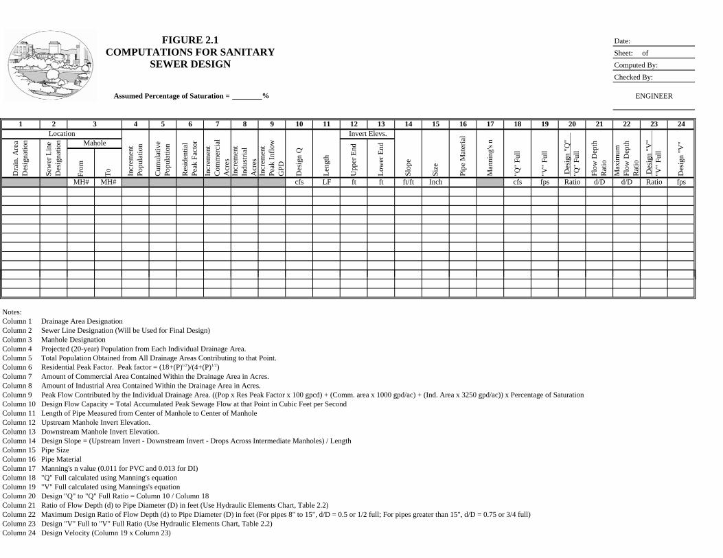
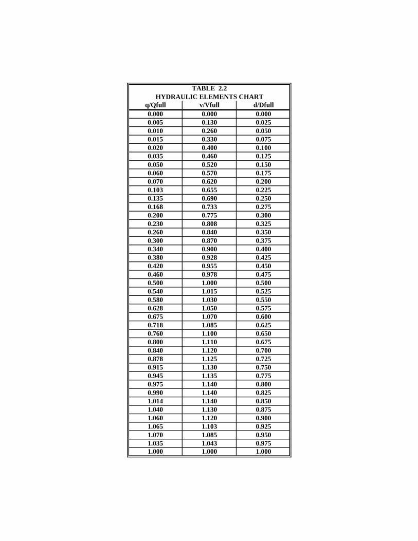
FIGURE 2.1 Date: COMPUTATIONS FOR SANITARY Sheet: of SEWER DESIGN Computed By:
Checked By:
Assumed Percentage of Saturation = % ENGINEER
1 2 4 5 6 7 8 9 10 11 12 13 14 15 16 17 18 19 20 21 22 23 24
From
To
MH# MH# cfs LF ft ft ft/ft Inch cfs fps Ratio d/D d/D Ratio fps
LocationIn
crem
ent
Popu
latio
n
Cum
ulat
ive
Popu
latio
n
Res
iden
tial
Peak
Fac
tor
Incr
emen
t C
omm
erci
al
Acr
esIn
crem
ent
Indu
stria
l A
cres
Incr
emen
t Pe
ak In
flow
G
PD
Des
ign
Q
3
Des
ign
"V"
"V"
Full
Pipe
Mat
eria
l
Man
ning
's n
"Q"
Full
"V"
Full
Leng
th
Invert Elevs.
Slop
e
Size
Des
ign
"V"
Dra
in. A
rea
Des
igna
tion
Sew
er L
ine
Des
igna
tion Mahole
Upp
er E
nd
Low
er E
nd
Des
ign
"Q"
"Q
" Fu
ll
Flow
Dep
th
Rat
io
Max
imum
Fl
ow D
epth
R
atio
Notes:Column 1 Drainage Area DesignationColumn 2 Sewer Line Designation (Will be Used for Final Design)Column 3 Manhole DesignationColumn 4 Projected (20-year) Population from Each Individual Drainage Area.Column 5 Total Population Obtained from All Drainage Areas Contributing to that Point.Column 6 Residential Peak Factor. Peak factor = (18+(P)1/2)/(4+(P)1/2)Column 7 Amount of Commercial Area Contained Within the Drainage Area in Acres.Column 8 Amount of Industrial Area Contained Within the Drainage Area in Acres.Column 9 Peak Flow Contributed by the Individual Drainage Area. ((Pop x Res Peak Factor x 100 gpcd) + (Comm. area x 1000 gpd/ac) + (Ind. Area x 3250 gpd/ac)) x Percentage of Saturation Column 10 Design Flow Capacity = Total Accumulated Peak Sewage Flow at that Point in Cubic Feet per SecondColumn 11 Length of Pipe Measured from Center of Manhole to Center of ManholeColumn 12 Upstream Manhole Invert Elevation.Column 13 Downstream Manhole Invert Elevation.Column 14 Design Slope = (Upstream Invert - Downstream Invert - Drops Across Intermediate Manholes) / LengthColumn 15 Pipe SizeColumn 16 Pipe MaterialColumn 17 Manning's n value (0.011 for PVC and 0.013 for DI)Column 18 "Q" Full calculated using Manning's equationColumn 19 "V" Full calculated using Mannings's equationColumn 20 Design "Q" to "Q" Full Ratio = Column 10 / Column 18Column 21 Ratio of Flow Depth (d) to Pipe Diameter (D) in feet (Use Hydraulic Elements Chart, Table 2.2)Column 22 Maximum Design Ratio of Flow Depth (d) to Pipe Diameter (D) in feet (For pipes 8" to 15", d/D = 0.5 or 1/2 full; For pipes greater than 15", d/D = 0.75 or 3/4 full)Column 23 Design "V" Full to "V" Full Ratio (Use Hydraulic Elements Chart, Table 2.2)Column 24 Design Velocity (Column 19 x Column 23)

FIGURE 2.2 Date:
COMPUTATIONS FOR SANITARY Sheet: 1 of 1
SEWER DESIGN Computed By: ABC
SATURATED GROWTH Checked By: ABC
Assumed Percentage of Saturation = 100% ENGINEEREngineer
1 2 4 5 6 7 8 9 10 11 12 13 14 15 16 17 18 19 20 21 22 23 24
From
To
MH# MH# cfs LF ft ft ft/ft Inch cfs fps Ratio d/D d/D Ratio fpsSB-1-3 N/A 37 33 0 0 4.50 0.0 153.2 497856 0.77 1028 651.60 646.42 0.0047 10 PVC 0.011 1.68 3.08 0.46 0.45 0.50 0.96 2.94SB-4 N/A 33 27 0 0 4.50 0.0 50.7 164661 1.03 1400 646.32 631.35 0.0103 10 PVC 0.011 2.48 4.54 0.41 0.43 0.50 0.93 4.22SB-5 N/A 27 20 0 0 4.50 0.0 76.1 247346 1.41 1363 631.25 621.22 0.0069 12 PVC 0.011 3.30 4.20 0.43 0.45 0.50 0.96 4.01SB-6 N/A 20 12 130 130 4.21 4.4 144.5 528916 2.23 1727 621.02 611.91 0.0049 15 PVC 0.011 5.02 4.09 0.44 0.45 0.50 0.96 3.90SB-7 N/A 12 7 593 724 3.89 30.4 79.0 517711 3.03 1425 611.81 604.50 0.0048 18 PVC 0.011 8.14 4.61 0.37 0.40 0.75 0.90 4.14SB-8 N/A 7 1 771 1495 3.68 39.7 78.0 577156 3.92 1380 604.40 600.80 0.0022 18 PVC 0.011 5.54 3.13 0.71 0.60 0.75 1.07 3.35SB-9 N/A 1 PS 1608 3103 3.43 84.7 0.0 636312 4.90 80 600.70 600.52 0.0022 18 PVC 0.011 5.54 3.14 0.88 0.73 0.75 1.13 3.53
Notes:
Date
Des
ign
"V"
Dra
in. A
rea
Des
igna
tion
Sew
er L
ine
Des
igna
tion Mahole
Upp
er E
nd
Low
er E
nd
Des
ign
"Q"
"Q
" Fu
ll
Flow
Dep
th
Rat
io
Max
imum
Fl
ow D
epth
R
atio
Man
ning
's n
"Q"
Full
"V"
Full
Leng
th
Invert Elevs.
Slop
e
Size
Incr
emen
t Pe
ak In
flow
G
PD
Des
ign
Q
3
Des
ign
"V"
"V"
Full
Pipe
Mat
eria
lLocationIn
crem
ent
Popu
latio
n
Cum
ulat
ive
Popu
latio
n
Res
iden
tial
Peak
Fac
tor
Incr
emen
t C
omm
erci
al
Acr
esIn
crem
ent
Indu
stria
l A
cres
Notes:Column 1 Drainage Area DesignationColumn 2 Sewer Line Designation (Will be Used for Final Design)Column 3 Manhole DesignationColumn 4 Projected (20-year) Population from Each Individual Drainage Area.Column 5 Total Population Obtained from All Drainage Areas Contributing to that Point.Column 6 Residential Peak Factor. Peak factor = (18+(P) 1/2)/(4+(P)1/2)Column 7 Amount of Commercial Area Contained Within the Drainage Area in Acres.Column 8 Amount of Industrial Area Contained Within the Drainage Area in Acres.Column 9 Peak Flow Contributed by the Individual Drainage Area. ((Pop x Res Peak Factor x 100 gpcd) + (Comm. area x 1000 gpd/ac) + (Ind. Area x 3250 gpd/ac)) x Percentage of Saturation Column 10 Design Flow Capacity = Total Accumulated Peak Sewage Flow at that Point in Cubic Feet per SecondColumn 11 Length of Pipe Measured from Center of Manhole to Center of ManholeColumn 12 Upstream Manhole Invert Elevation.Column 13 Downstream Manhole Invert Elevation.Column 14 Design Slope = (Upstream Invert - Downstream Invert - Drops Across Intermediate Manholes) / LengthColumn 15 Pipe SizeColumn 16 Pipe MaterialColumn 17 Manning's n value (0.011 for PVC and 0.013 for DI)Column 18 "Q" Full calculated using Manning's equationColumn 19 "V" Full calculated using Mannings's equationColumn 20 Design "Q" to "Q" Full Ratio = Column 10 / Column 18Column 21 Ratio of Flow Depth (d) to Pipe Diameter (D) in feet (Use Hydraulic Elements Chart, Table 2.2)Column 22 Maximum Design Ratio of Flow Depth (d) to Pipe Diameter (D) in feet (For pipes 8" to 15", d/D = 0.5 or 1/2 full; For pipes greater than 15", d/D = 0.75 or 3/4 full)Column 23 Design "V" Full to "V" Full Ratio (Use Hydraulic Elements Chart, Table 2.2)Column 24 Design Velocity (Column 19 x Column 23)
3-1
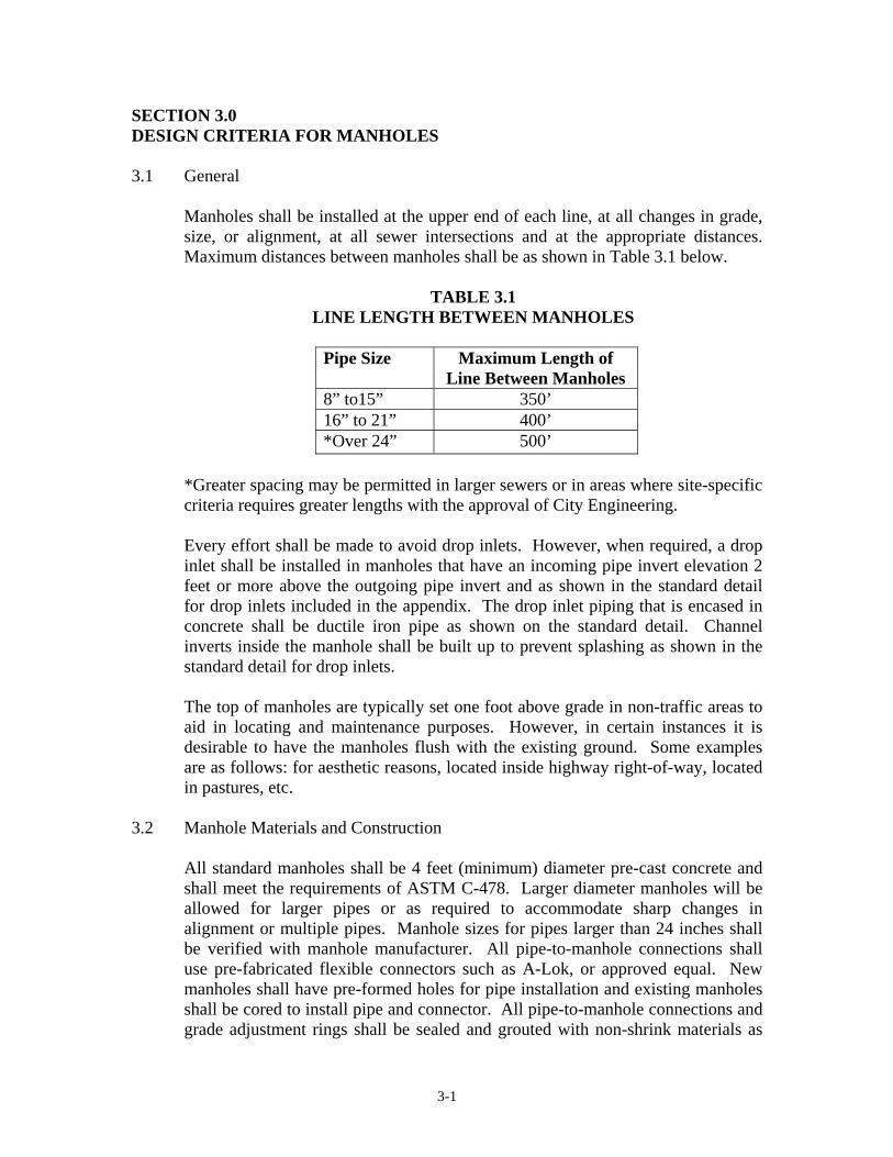
SECTION 3.0 DESIGN CRITERIA FOR MANHOLES 3.1 General
Manholes shall be installed at the upper end of each line, at all changes in grade, size, or alignment, at all sewer intersections and at the appropriate distances. Maximum distances between manholes shall be as shown in Table 3.1 below.
TABLE 3.1 LINE LENGTH BETWEEN MANHOLES
Pipe Size Maximum Length of
Line Between Manholes 8” to15” 350’ 16” to 21” 400’ *Over 24” 500’
*Greater spacing may be permitted in larger sewers or in areas where site-specific criteria requires greater lengths with the approval of City Engineering.
Every effort shall be made to avoid drop inlets. However, when required, a drop inlet shall be installed in manholes that have an incoming pipe invert elevation 2 feet or more above the outgoing pipe invert and as shown in the standard detail for drop inlets included in the appendix. The drop inlet piping that is encased in concrete shall be ductile iron pipe as shown on the standard detail. Channel inverts inside the manhole shall be built up to prevent splashing as shown in the standard detail for drop inlets. The top of manholes are typically set one foot above grade in non-traffic areas to aid in locating and maintenance purposes. However, in certain instances it is desirable to have the manholes flush with the existing ground. Some examples are as follows: for aesthetic reasons, located inside highway right-of-way, located in pastures, etc.
3.2 Manhole Materials and Construction
All standard manholes shall be 4 feet (minimum) diameter pre-cast concrete and shall meet the requirements of ASTM C-478. Larger diameter manholes will be allowed for larger pipes or as required to accommodate sharp changes in alignment or multiple pipes. Manhole sizes for pipes larger than 24 inches shall be verified with manhole manufacturer. All pipe-to-manhole connections shall use pre-fabricated flexible connectors such as A-Lok, or approved equal. New manholes shall have pre-formed holes for pipe installation and existing manholes shall be cored to install pipe and connector. All pipe-to-manhole connections and grade adjustment rings shall be sealed and grouted with non-shrink materials as

3-2
specified in the City of Huntsville Sanitary Sewer Specifications. All lift holes except those in cone section shall also be grouted with the non-shrink grout. Lift holes shall not penetrate the wall of the manhole. Manholes shall include a manhole lift system as specified in the City of Huntsville Sanitary Sewer Specifications. All manholes shall be backfilled and tested according to City of Huntsville Sanitary Sewer Specifications and Details.
3.3 Flow Channel
The flow channel shall conform in shape and size to that of the connecting sewers. Minimum drops shall be increased when curved flow channels are required inside manholes. Refer to paragraph 3.7 for additional information.
3.4 Bench
When pipe diameters are less than 48 inches, a bench shall be provided on each side of the flow channel. The bench slope shall be 1 inch per foot. No pipe shall discharge onto the bench surface.
3.5 Manhole Types
Shallow Manhole: A shallow manhole is defined as any manhole that is 5 feet or less in depth, as measured from the invert of the manhole base at its center to the finished ground. Every effort shall be made to avoid using shallow manholes.
Standard Manhole: A standard manhole is defined as any manhole that is greater than 5 feet in depth, as measured from the invert of the manhole base at its center to the finished ground.
3.6 Manhole Frames, Covers, and Vents
Shallow and standard manholes shall be equipped with traffic-type frames and covers as shown in Appendix B. Sanitary sewer manholes proposed within the 100-year flood boundary shall be designed with the rim elevation a minimum of 1’ above the 100-year flood elevation. Manhole rims shall be installed no higher than 3’ above the ground surface to allow easy access to the manhole. In an area where the 100-year flood elevation will cause the manhole rim to exceed 3’ above the ground surface, the manhole rim shall be installed flush with the ground surface and shall be equipped with a watertight frame and cover and a manhole vent shall be installed. In cases where multiple manholes are required to be equipped with vents, a manhole vent shall be installed at every other manhole. All watertight manhole covers shall be bolted to the frame. See Appendix B for watertight frame and cover and vent details.

3-3
Manholes requiring a vent and located within an easement or other areas where raised manholes are not allowed will be required to be constructed with a flat top, as shown on Standard Detail SD-23 in Appendix B. Flat-top manholes will not be allowed for manholes located within traffic areas. Manholes proposed adjacent to drainage ditches, or drainage structures in which there is a potential problem of storm water entering the sanitary sewer, shall be equipped with watertight frames and covers. All manhole frame and covers shall include butyl sealant (ram neck) under the flange of the manhole frame prior to grouting as shown in Appendix B.
3.7 Hydraulic Grade Lines
The hydraulic grade line or energy grade line of flow through a manhole shall always be designed to stay within the crown of the pipe. When the pipe size does not change, or increases by only one pipe size, a minimum elevation drop of 0.1 foot shall be applied to the invert of the outgoing pipe. When the pipe will change directions by 90 degrees inside the manhole, a minimum elevation drop of 0.2 foot shall be applied to the invert of the outgoing pipe. Calculations shall be performed to insure that the hydraulic grade line stays within the crown of the pipe when there is reason for concern. These calculation checks may be performed by hand calculations or with the aid of computer software.
3.8 Location of Manholes
Manholes located in easements shall be placed outside areas subject to flooding or runoff when possible. Manholes located in streets shall be placed a minimum of 5 feet from the edge of the curb or pavement. Every effort shall be made to place the entire manhole frame and cover within the pavement limits. Manholes shall be positioned outside the normal tire path of vehicles.
3.9 Connecting to Existing Sewers
When connecting a new sewer line to an existing manhole, the existing manhole shall be core drilled and flexible connectors, such as A-Lok or approved equal, installed to connect the pipe. When connecting new manholes to existing sewers, the new manholes shall be equipped with flexible connectors, such as Kor-N-Seal or approved equal. The new sewer line or manhole shall be connected to the existing sewer line as shown in the standard details included in the appendix.

3-4
3.10 Abandoned Manholes and Sewer Lines All piping connected to abandoned manholes shall be plugged and filled with 24” of grout fill or flowable fill at each end as shown on the standard details. The manhole top shall be removed down to not less than 3 feet below final grade and the remaining portion shall be filled with crushed rock and capped with 12” of concrete or filled with flowable fill as shown on the standard details.
3.11 Testing Requirements
The City of Huntsville Engineering Department requires testing of all new public and private sanitary sewer lines and manholes. Minimum testing requirements are included in the City of Huntsville Sanitary Sewer Construction Specifications (see Appendix C). The Contractor shall receive approval of all as-built drawings and the City of Huntsville shall issue all manhole numbers to the Contractor prior to conducting any television inspection activities. The City of Huntsville shall review and approve all television inspection logs prior to the commencement of testing procedures. The Contractor must provide a 72-hour notice prior to testing. A representative from the Engineering Department and/or Water Pollution Control must be present during final testing procedures. An independent testing firm as approved by the Engineering and Water Pollution Control Departments shall conduct testing. A list of approved testing firms is available from Water Pollution Control. All testing costs shall be included in the costs of manholes and pipes. A copy of all as-built drawings, television inspection files, and testing results shall be submitted to Water Pollution Control.
3.12 Lateral Connections All lateral connections made at a manhole shall be made with the invert of the lateral connection equal to the crown of the exiting (downstream) sewer main line.

4-1
SECTION 4.0 DESIGN CRITERIA FOR SEWER LINES 4.1 Sizing of Pipe
Design calculations for sizing pipe shall be conducted using the following criteria:
• For pipe sizes 8” to 15”, design for ½ full depth flow*. • For pipe sizes greater than 15”, design for ¾ full depth flow*.
* References:
1. “Master Sewer Plan, City of Huntsville”, April 1997 (currently under revision).
2. “Gravity Sanitary Sewer Design and Construction”, ASCE Manuals and Reports on Engineering Practice No. 60, WPCF Manual of Practice No. FD-5.
The appropriate pipe size and slope to transport the design flow shall be calculated using Manning’s Equation as shown below. The minimum pipe size for sanitary sewer in the City of Huntsville is 8 inch. The minimum design velocity is 2 feet/second. A roughness coefficient of n = 0.013 for ductile iron (n = 0.011 for PVC) shall be used for sanitary sewers.
Manning’s Equation
V (fps) = (1.486/n)R2/3S1/2
Where n = Roughness Coefficient R = Hydraulic Radius, ft = Area/Wetted Perimeter S = Slope, ft/ft
Manning’s Equation for Pipes Flowing Full
V (fps) = (0.590/n)D2/3S1/2 or Q (cfs) = (0.463/n)D8/3S1/2
Where n = Roughness Coefficient D = Pipe Diameter, ft S = Slope, ft/ft

4-2
4.2 Geotechnical Studies
A geotechnical study shall be conducted in project areas suspected of rock bedding. Rock soundings shall be at intervals not to exceed 350 to 500 (should match manhole location intervals) feet along the centerline of the proposed sewer and to at least one foot below the depth of the sewer at the location of the sounding. If rock is encountered, then the soundings shall be conducted at closer intervals determined by the Design Engineer and/or City Engineering.
4.3 Surveying of Sanitary Sewer Lines
A professional land surveyor licensed in the State of Alabama shall conduct the survey of the proposed sanitary sewer line. The surveyor shall stake out the proposed sewer line as follows: stake each manhole’s proposed centerline location with offset referencing, reference each P.I. in the field, and note all benchmarks in the field and on the Plans. The surveyor shall provide drawings meeting all requirements of City of Huntsville. Refer to paragraph 4.8, of this Section for additional information.
4.4 Minimum Cover
All sanitary sewers shall have a minimum cover of 3 feet (36”). Special cases will require approval from City Engineering. Trench bedding and backfill requirements shall be per City of Huntsville Standard Details and Specifications (see Appendix C).
4.5 Pipe Materials and Ratings
Listed in Table 4.1 are several general ways to determine which pipe material is best suited for a particular project. Reinforced concrete pipe, ductile iron pipe, and polyvinyl chloride pipe are the City of Huntsville accepted sanitary sewer pipe materials. Use of all other pipe materials must have prior written approval from City Engineering. All gravity and force main piping specified below shall be bedded per City of Huntsville standard details. The same pipe material shall extend from manhole to manhole. No pipe material changes will be allowed between manholes. The minimum design criteria for each pipe material are discussed below. For additional specifications, refer to the City of Huntsville Standard Specifications included in the appendix.

4-3
TABLE 4.1 PIPE MATERIAL SELECTION
No. Laying Condition Required Pipe Material to Specify* 1 For grades less than 0.60% DIP or PVC ***
2 For grades from 0.60% to 12.00% DIP or PVC 3
For grades from 12.00% to 20.00%. ** DIP with no anchors.
4
For grades from 20.00% to 34.00%. ** DIP with anchors required each 36 feet center to center.
5
For grades from 35.00% and up to 50.00%. **
DIP with anchors required each 24 feet center to center.
6 For grades greater than 50.00%. ** DIP with anchors required each 16 feet center to center.
7 For areas where proposed pipe is to be within filled areas.
DIP
8 For areas where proposed sewer is at depths greater than 15 feet.
DIP Note: Any service risers to DIP from this depth shall also be DIP.
9 For areas within backyard and side lot utility and drainage easement or other difficult to access areas.
DIP
10 For crossing ditches and/or streams. DIP (reinforced concrete encasement shall be required if minimum cover is less than 3 feet) see standard drawing
11 For areas where proposed pipe is at depths less than 5 feet and under traffic conditions
DIP
12 For crossing existing pipe and roadways. DIP (steel encasement may be required on certain projects.)
13 For boring lines. DIP
*All pipe materials shall meet minimum requirements as specified in this manual and in the City of Huntsville Specifications. **The surface area is to be stabilized for grades in excess of 12% (sod, etc.). Steep grades that produce pipe velocities greater than 10.0 fps (Refer to page 4-8) will require prior approval from City Engineering.
***RCP will only be allowed where required pipe size exceeds maximum size available in DIP.
4.5.1 Reinforced Concrete Pipe (RCP)

4-4
RCP shall only be used where the required pipe size exceeds the maximum size allowable in ductile iron pipe.
Reinforced Concrete Pipe for gravity flow shall conform to the requirements specified in ASTM C76. Non-air-entraining portland cement with a 28-day compressive strength of not less than 4,000 psi conforming to the requirements of ASTM C150 shall be used. The interior of the RCP shall be lined with a high build, 2-component amine cured epoxy system. The spigot ends shall be coated to give full protection to the area exposed in the bell of the joint. The coatings and/or liners shall meet requirements or specifications of the manufacturer for a sanitary sewer line. All RCP pipe shall meet the following requirements: • Standard lengths of at least 8 feet are required, except for end pieces
and special pieces. • Pipe shall be marked as required by ASTM C76. • Rubber gaskets for pipe joints shall be in accordance with ASTM
C361 and C443. • A 72-hour notice shall be required prior to testing procedures. All
final inspections and testing procedures shall be conducted with a representative of City Engineering and Water Pollution Control present.
• Bedding and backfill requirements shall be as specified in City of Huntsville Sanitary Sewer Specifications.
• Additional requirements can be found in the City of Huntsville, Standard Specifications. (see section 645-8)
4.5.2 Ductile Iron Pipe (DIP)
Pipe Size Minimum
Pressure Class Up to and including 12” 350 14” up to and including 24” 250 Greater than 24” 150 Above Ground Pipe – Up to and including 12” 350 Above Ground Pipe – Greater than 12” 250
4-5
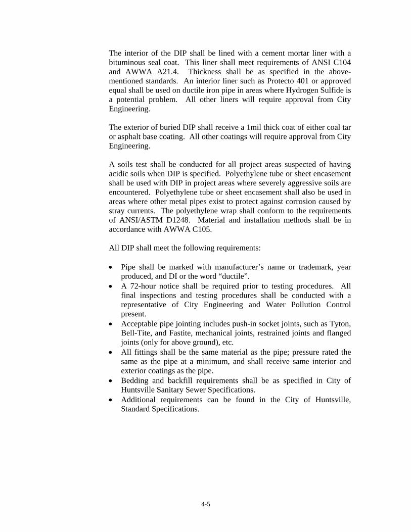
The interior of the DIP shall be lined with a cement mortar liner with a bituminous seal coat. This liner shall meet requirements of ANSI C104 and AWWA A21.4. Thickness shall be as specified in the above-mentioned standards. An interior liner such as Protecto 401 or approved equal shall be used on ductile iron pipe in areas where Hydrogen Sulfide is a potential problem. All other liners will require approval from City Engineering. The exterior of buried DIP shall receive a 1mil thick coat of either coal tar or asphalt base coating. All other coatings will require approval from City Engineering. A soils test shall be conducted for all project areas suspected of having acidic soils when DIP is specified. Polyethylene tube or sheet encasement shall be used with DIP in project areas where severely aggressive soils are encountered. Polyethylene tube or sheet encasement shall also be used in areas where other metal pipes exist to protect against corrosion caused by stray currents. The polyethylene wrap shall conform to the requirements of ANSI/ASTM D1248. Material and installation methods shall be in accordance with AWWA C105. All DIP shall meet the following requirements: • Pipe shall be marked with manufacturer’s name or trademark, year
produced, and DI or the word “ductile”. • A 72-hour notice shall be required prior to testing procedures. All
final inspections and testing procedures shall be conducted with a representative of City Engineering and Water Pollution Control present.
• Acceptable pipe jointing includes push-in socket joints, such as Tyton, Bell-Tite, and Fastite, mechanical joints, restrained joints and flanged joints (only for above ground), etc.
• All fittings shall be the same material as the pipe; pressure rated the same as the pipe at a minimum, and shall receive same interior and exterior coatings as the pipe.
• Bedding and backfill requirements shall be as specified in City of Huntsville Sanitary Sewer Specifications.
• Additional requirements can be found in the City of Huntsville, Standard Specifications.

4-6
4.5.3 Polyvinyl Chloride Pipe (PVC)
PVC pipe will only be allowed for pipe diameters of 8” and 10” on mainlines unless written approval is obtained from City Engineering. They shall be minimum SDR 26 (ASTM D-3034). The PVC pipe shall be installed according to standard details and specifications for the appropriate trench type. The standard details are included in the appendix.

4-7
All PVC pipe shall meet the following requirements: • Standard lengths of at least 12 feet 6 inches are required. Longer
sections will be permitted. • Pipe shall be marked with manufacturer’s name, production lot
number, ASTM designation, PVC, SDR rating, and nominal diameter. • A 72-hour notice shall be required prior to testing procedures. All
final inspections and testing procedures shall be conducted with a representative of City Engineering and Water Pollution Control present.
• Bedding and backfill requirements shall be as specified in City of Huntsville Sanitary Sewer Specifications.
• Additional requirements can be found in the City of Huntsville, Standard Specifications.
4.6 Slopes
The minimum allowable slopes for each pipe size are displayed in Table 4.2 and the maximum allowable slopes for each pipe size are displayed in Table 4.3. These slopes were calculated using Manning’s Equation with a Roughness coefficient of n = 0.011 (PVC) and n = 0.013 (DIP, RCP) as shown. The last run or segment of sewer at the upper end of a collector system shall have a minimum slope of 0.010 foot per foot or greater. This will allow for proper drainage of this dead end line.

4-8
TABLE 4.2 MINIMUM ALLOWABLE SLOPES
Pipe Diameter (inches)
Slope (ft/ft) Velocity (ft/sec) Full (for n = 0.011)
Velocity (ft/sec) Full (for n = 0.013)
8 0.0050 2.9 2.5 10 0.0035 2.8 2.4 12 0.0022 2.1 16 0.0015 2.0 18 0.0012 2.0 21 0.0010 2.1 24 0.0008 2.0 27 0.00067 2.0 30 0.00058 2.0 36 0.00046 2.0 42 0.00037 2.0 48 0.00030 2.0 54 0.00026 2.0 60 0.00026 2.0 66 0.00026 2.3 72 0.00026 2.4 78 0.00026 2.6
Table 4.3
MAXIMUM ALLOWABLE SLOPES
Pipe Diameter (inches)
Velocity (ft/sec) Full*
Slope (ft/ft) (for n = 0.011)
Slope (ft/ft) (for n = 0.013)
8 10.0 0.05970 0.08339 10 10.0 0.04433 0.06192 12 10.0 0.04855 16 10.0 0.03605 18 10.0 0.02827 21 10.0 0.02301 24 10.0 0.01926 27 10.0 0.01646 30 10.0 0.01430 36 10.0 0.01121 42 10.0 0.00913 48 10.0 0.00764 54 10.0 0.00653 60 10.0 0.00567 66 10.0 0.00500 72 10.0 0.00445 78 10.0 0.00400
*Steep grades that produce pipe velocities greater than 10.0 fps will require prior approval from City Engineering. Reference: Design and Construction of Sanitary and

4-9
Storm Sewers, WPCF Manual of Practice No. 9, ASCE Manual on Engineering Practice No. 37, 1970 (Fifth Printing 1982), Water Pollution Control Federation.
4.6.1 The minimum allowable design slope on 8” gravity sewer lines shall be 0.50%. Approval by the City of Huntsville’s Engineering Department is required for designs implementing slopes on 8” sanitary sewers less than 0.50%.
4.6.2 The minimum allowable design slope on 10” gravity sewer lines shall be
0.35%. Approval by the City of Huntsville’s Engineering Department is required for designs implementing slopes on 10” sanitary sewers less than 0.35%.
4.7 Easements
Installation of sanitary sewer facilities to be maintained by the City of Huntsville shall be constructed within dedicated rights-of-way and utility and drainage easements if available. If no existing easements are available for the proposed sewer, easement plats must be surveyed and prepared by a licensed professional land surveyor and submitted to the City. These documents must include a legal description of the easement(s), legal owner’s name, and Deed Book and Page. A licensed State of Alabama professional land surveyor must stamp easement plats. All easement plat submittals (hard copies and digital copies) shall meet the requirements of the Land Acquisition Department. These requirements are available from City Engineering.
Special easements such as Railroad Crossings, TVA crossings, and State Highway crossings will require special permitting. The Design Engineer shall be required to submit copies of the plans showing crossings to the appropriate agencies and obtain all necessary permits.
Table 4.4 displays the standard minimum permanent easement requirements and recommended temporary easements for different size sewer pipe. Written approval from City Engineering shall be required for additional permanent easement or for decreasing permanent easement widths. The Design Engineer and/or City Engineering shall set the temporary easement widths. The Contractor is required to conduct work in accordance with all safety requirements set by OSHA and all other regulatory agencies.

4-10
TABLE 4.4 EASEMENT WIDTHS
Pipe Diameters Minimum Width Permanent Easement*
Recommended Additional Width for Temporary Construction Easement (TCE)**
8” through 12” 15 ft 20 ft 14” through 54” 30 ft 20 ft 60” and larger 50 ft 0 ft
*Additional permanent easement may be required on lines with depths greater than 8 feet. City Engineering and Water Pollution Control shall determine this additional easement. **Additional temporary easements are based on trench side slope of 3:1. Additional temporary easements or trench boxes will need to be used on pipe depths greater than 5 feet. 4.8 Utility Crossings
Sanitary sewer lines shall be installed below water mains. A minimum of 10 feet of horizontal clearance between sanitary sewers and water mains shall be maintained. A minimum vertical separation of 18 inches should be maintained between sanitary sewers and water mains. Written approval from City Engineering and Huntsville Utilities is required in cases where these minimum requirements cannot be obtained. A utility crossing detail can be found in the City of Huntsville Standard Details. Other utility crossings shall maintain clearances as specified by Huntsville Utilities and City Engineering.
4.9 Stream Crossings Ductile iron pipe will be required at all creek, stream and ditch crossings. Reinforced concrete encasement shall be required when crossing creeks, streams or ditches if minimum cover of 3 feet cannot be maintained. DIP shall extend from manhole to manhole. Sewer lines shall cross the streams or creeks as near perpendicular to stream flow as possible. The Design Engineer shall be responsible for obtaining all necessary permitting when crossing streams or creeks unless otherwise specified. The Design Engineer shall also be responsible for meeting the design specifications for the permitting. An evaluation of the stream crossing shall be conducted by the Design Engineer to investigate conditions such as the vulnerability of the stream to meander and/or scour. Historical information such as stream scour data is available for review from City Engineering. The stream crossing detail shall then be selected and/ or modified to reflect the minimum requirements established by the permitting agency as well as the limits shown based on the above criteria as well as other applicable conditions. Standard details for these items are included in the appendix.

4-11
4.10 Crossing Existing Roadways Sanitary sewers crossing under existing City/County roadways shall be installed by either open trenching or bore and jack with steel encasement pipe as approved by City Engineering. Open trench installation on county roadways will require written permission from the County Engineer. Sanitary sewers crossing existing State roadways shall be installed by bore and jack with steel encasement. The Design Engineer shall prepare all necessary state roadway-crossing permit applications. Ductile iron pipe is required for crossing under all existing roadways. City Engineering shall determine the use of casing pipes on existing roadways. The Design Engineer shall prepare all required roadway-crossing permit applications. Standard details for these items are included in the appendix.
4.11 Testing Requirements
City Engineering requires testing of all new public and private sanitary sewer lines and manholes. Minimum testing requirements are included in the City of Huntsville Sanitary Sewer Specifications. All testing costs shall be included in the costs for manholes and pipes. An independent testing firm as approved by City Engineering and Water Pollution Control shall conduct testing, and a list of approved testing firms is available from Water Pollution Control. The Contractor must provide a 72-hour notice to Water Pollution Control prior to testing. A representative from City Engineering and Water Pollution Control must be present during final testing procedures. A copy of all tapes and logs on testing results shall be submitted to Water Pollution Control.
5-1
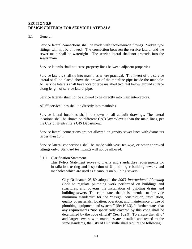
SECTION 5.0 DESIGN CRITERIA FOR SERVICE LATERALS 5.1 General
Service lateral connections shall be made with factory-made fittings. Saddle type fittings will not be allowed. The connection between the service lateral and the sewer main shall be watertight. The service lateral shall not protrude into the sewer main. Service laterals shall not cross property lines between adjacent properties. Service laterals shall tie into manholes where practical. The invert of the service lateral shall be placed above the crown of the mainline pipe inside the manhole. All service laterals shall have locator tape installed two feet below ground surface along length of service lateral pipe. Service laterals shall not be allowed to tie directly into main interceptors. All 6” service lines shall tie directly into manholes. Service lateral locations shall be shown on all as-built drawings. The lateral locations shall be shown on different CAD layers/levels than the main lines, per the City of Huntsville’s GIS Department.
Service lateral connections are not allowed on gravity sewer lines with diameters larger than 10”.
Service lateral connections shall be made with wye, tee-wye, or other approved fittings only. Standard tee fittings will not be allowed. 5.1.1 Clarification Statement
This Policy Statement serves to clarify and standardize requirements for installation, testing and inspection of 6” and larger building sewers, and manholes which are used as cleanouts on building sewers:
City Ordinance 05-80 adopted the 2003 International Plumbing Code to regulate plumbing work performed on buildings and structures, and governs the installation of building drains and building sewers. The code states that it is intended to “provide minimum standards” for the “design, construction, installation, quality of materials, location, operation, and maintenance or use of plumbing equipment and systems” (Sec101.3). It further states that any requirements “not specifically covered by this code shall be determined by the code official” (Sec 102.9). To ensure that all 6” and larger sewers with manholes are installed and tested to the same standards, the City of Huntsville shall require the following:

5-2
Building sewers which are 6” and larger, with any manholes, shall be designed, installed, and tested in accordance with the requirements of the City of Huntsville’s Design and Acceptance Manual for Sanitary Sewers (Engineering Dept). Specifically, this requires air testing and CCTV of lines and vacuum testing of manholes by a City approved independent contractor, with Water Pollution Control Dept. (WPC) personnel present to observe the test. WPC requires a 72 hour notice to schedule a test observation. Tests should be scheduled by the contractor with WPC’s Wastewater Collection Division at 883-3792.
5.2 Service Lateral Diameters
Residential service laterals shall not be less than 4” in diameter. 5.3 Pipe Materials and Ratings
Service lateral pipes which originate on the mainline shall be the same pipe material as the mainline unless nearby utilities pose problems. However, in the case of service laterals that span roadways, they shall be ductile iron only. Ductile iron pipe service laterals shall be minimum Pressure Class 350. Polyvinyl Chloride service laterals shall be minimum schedule 40. Pipe material shall stay the same from manhole to manhole.
5.4 Installation of Residential Service Laterals
Service laterals shall be installed for each lot or property a minimum of 5 feet beyond the right-of-way or easement line. The service laterals shall be installed at the low point of the lot or property when not in conflict with existing utilities. Standard details for service laterals are included in the Appendix. Service laterals shall extend a minimum of 15’ beyond the adjacent right-of-way or a minimum of 5’ beyond the adjacent easement.
5.5 Installation of Commercial/Industrial Service Laterals
A manhole shall be installed at the edge of easement or property line in lieu of a cleanout on all industrial/commercial service lines greater than or equal to 6 inches in diameter.
5.6 Permanent Curb Markers for Service Laterals
A permanent marker shall be installed on the curb face at a point which intersects with the service lateral. Curb markers shall be glued or otherwise permanently attached to the curb face at a point which intersects with the service lateral.

5-3
Curb markers shall be 2 ½” circular-shaped made of UVHDPE material utilizing a two-color face. The curb marker shall be manufactured by Almetek or approved equal.
5.7 Oil, Water, and Grease Separation
A grease trap shall be required to receive the drainage from fixtures and equipment with grease-laden waste located in food preparation areas, such as in restaurants, hotel kitchens, hospitals, school kitchens, bars, factory cafeterias, or restaurants and clubs.
A grease trap shall not be required for individual dwelling units or any private living quarters.
Such minimal pretreatment requires passage through a grease trap meeting the City's engineering standards and providing a minimum retention time of ten minutes between influent and effluent baffles with 20 percent of the total volume as allowance for a sludge pocket.
5.8 Lateral Connections to Manholes All lateral connections made at a manhole shall be made with the invert of the lateral connection equal to the crown of the exiting (downstream) sewer main line.

6-1
SECTION 6.0 PLAN SET REQUIREMENTS 6.1 Standard Requirements for Plan Sets
The following standard requirements are guidelines for the preparation of sanitary sewer plans and should not be construed as being the total requirements. City Engineering may at its option require additions to be made in the plans where circumstances warrant. An example plan set is shown at the end of this section.
1. Plans shall be prepared on standard 24” x 36” plan and profile sheets. 2. A cover sheet containing the name of the project, date, city project numbers,
mayor, city engineer, city council members, and engineering firm with address and phone numbers, etc. shall be included in all plans.
3. A general sheet containing a location map at an approximate scale of not less
than 1” = 1000 feet, a legend, abbreviation listing, general notes, and index of drawings shall be included in all plans.
4. Plan views shall be drawn at a scale of 1” = 50 feet and profiles shall be
drawn at a scale of 1” = 50 feet horizontal and 1” = 5 feet or 1” = 10 feet vertical. In areas where existing topographic features are dense, detail sheets at a scale of 1” = 20 feet with the clearance from the proposed main to existing structures clearly defined and noted may be required. The project legend shall be shown on each plan sheet as well as the general sheet when practical.
5. Standard Detail sheets shall include all details required for the project. The
details must be the standards accepted by the City of Huntsville as shown in the appendix of this manual. If a required detail is not available in the City of Huntsville standards, the Engineer shall submit a recommended detail for approval by City Engineering.
6. An Alabama licensed professional engineer shall seal and sign all plans.
7. All plans shall contain the following notes:
a. The intent of the drawings is that the contractor shall furnish all labor,
materials, tools, equipment and transportation necessary for the proper execution of the work in accordance with the Contract Documents and all incidental work necessary to complete the project in an acceptable manner, ready for use, occupancy or operation by the owner.
b. Efforts have been made to indicate locations of existing structures, piping,
utilities, and topography. However, it is the contractor’s responsibility to

6-2
field verify exact measurements and locations of all existing items before initiating any construction operations. Any existing structure, piping or utility disturbed or damaged by the contractor during construction operations shall be replaced by the contractor at no additional cost to the owner and/or engineer. Sufficient advance coordination of disruption with the owner of any facility is the total responsibility of the contractor.
c. The limits of construction shall be the property lines or easement lines as
shown on the plans. The contractor shall acquire any additional easements required for construction at no additional expense to the owner and\or engineer.
d. Existing grading and drainage elevations shall be maintained after
construction unless otherwise shown on plans.
e. All buried pipes shall have a minimum of 3'-0" cover as measured vertically from finished grade to the top of pipe, unless otherwise noted.
f. It shall be the contractor's responsibility to work all applicable Drawings
and the appropriate specifications as a unit. Any omissions, deletions, or conflicts arising as a result of failure to incorporate all drawings and specifications that apply shall be corrected by the Contractor at no additional cost to the Owner and\or Engineer.
g. All sewer construction shall be in accordance with the “Standard
Specifications for the Construction of New Sanitary Sewers” latest edition.
h. The contractor shall be totally responsible for TVI, vacuum testing manholes and air testing sewer lines. A 72-hour notice is required prior to testing procedures. Representatives from both the City Engineering office and Water Pollution Control shall be present to verify testing results.
i. The Contractor shall provide the City Engineer with a complete set of
record drawings (as-builts) in digital Microstation (.dgn) and hardcopy format, and the Contractor/Inspector red-lined drawings upon completion of construction. Drawings shall be referenced to Alabama State Plane Coordinate System, NAD83 Alabama East Zone as described in the "Code of Alabama" (1975), section 35-2-1. Surveys shall be tied to a minimum of two accepted GPS monuments or one GPS tie point plus an astronomic observation to determine grid north. A land surveyor licensed in the State of Alabama shall complete the survey. In addition, the record drawings shall show final vertical and horizontal alignment of all buried utilities added or moved as a result of construction. They shall include actual field angles between lines, all service lines and tee locations, all valve vaults and valve boxes, stubouts, and lines, and shall reflect all alignment and grade changes from the design Drawings made during construction.

6-3
Record drawings must be completed and submitted prior to acceptance of the sewers into the public system and any connections being made thereto.
j. The Engineer shall provide geotechnical information such as borings, soil
tests, etc upon written request.
k. All concrete, asphalt driveways and other road accesses, shall be sawcut and repaired in as good or better condition as before construction. Property owners shall have access to property at all times during construction.
l. Contractor shall supply and install service connections and flex
connections in manholes at elevations and deflections as noted on plans for all service laterals shown.
m. Service laterals and stubouts shall be extended to property or easement
lines as shown on plans.
n. Seed, fertilize, and mulch all disturbed areas during construction.
o. Fencing may be removed for construction purposes only. Fences shall be reinstalled in their original positions and in as good or better condition as before construction with exception of fence along interstate R.O.W. in which no fence shall be disturbed.
p. Contractor shall maintain a 15' minimum excavation clearance at all
transmission line tower supports and down guy anchors.
q. Contractor shall coordinate in advance and during construction operations with the owner of any fiber optic communication cables in the areas where these utilities may exist.
r. Traffic control shall be maintained per the "Manual on Uniform Traffic
Control Devices”, latest revision.
s. The contractor shall be responsible for obtaining and complying with NPDES stormwater permits during entire construction period. A copy of the ADEM permit shall be provided to the City Engineer and maintained on site at all times.
8. All plans shall show the locations of existing and proposed utilities, including
but not limited to gas lines, underground telephone, power, and telephone poles, water mains, sanitary sewer lines, storm sewers, etc.
9. All sewer plans shall include a Bench Mark based on U.S.G.S Datum or NAD
1983 Alabama East Zone. Plans that use a manhole invert elevation or an assumed elevation will not be approved.

6-4
10. Limits of easements shall be shown on the plans.
11. Show all planimetric features such as driveways, pavement, rights-of-way,
property lines, storm drainage, structures, archaeological sites, etc.
12. The direction of North shall be clearly noted on each plan sheet.
13. An Engineering Report shall be submitted with the plans, including criteria justifying the proposed sizing unless City Engineering specifies otherwise. (As required in Section 2)
14. All property lines shall be shown on the plans with Owners and Deed Book
and Page noted on plans.
15. A service connection must be provided for each piece of property, parcel or lot. The connection shall be shown as a standard pre-manufactured wye connection and an appropriately sized service line extension (4-inch minimum) to the right-of-way or edge of easement. Handmade Tee’s and “Y” connections are not acceptable. A manhole shall be installed at the end of the service connection for all services equal to or greater than 8-inch.
16. Stationing shall increase upstream with Station 0+00.00 being at the
downstream end.
17. State Revolving Fund (SRF) projects will require a set of specifications and a half-size set of plans to be submitted to ADEM for review prior to the bid.
18. All City of Huntsville standard details and specifications are included in the
appendix of this manual. A checklist for submittal purposes is included in Section 8 as well.
6.2 Design Engineer Specification Requirements
Technical specifications prepared by the Design Engineer shall accompany each set of sanitary sewer design plans when required by City Contract. The specifications shall be stamped and signed by a State of Alabama licensed professional engineer. Minimum criteria for the specifications are as follows: 1. Specifications shall be organized according to the sixteen-division format of
the Construction Specifications Institute (CSI). 2. Projects to be funded under the SRF program shall have the ADEM front-end
specifications incorporated.
3. Specifications at a minimum shall include instructions to the Contractor regarding the following items.
6-5
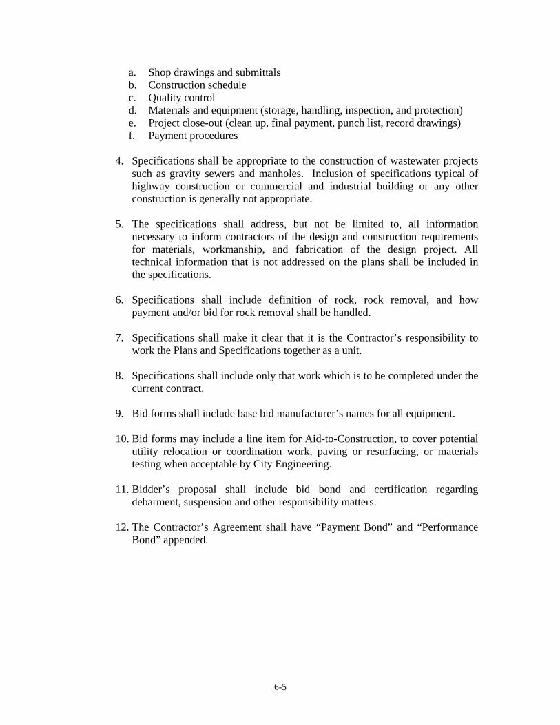
a. Shop drawings and submittals b. Construction schedule c. Quality control d. Materials and equipment (storage, handling, inspection, and protection) e. Project close-out (clean up, final payment, punch list, record drawings) f. Payment procedures
4. Specifications shall be appropriate to the construction of wastewater projects
such as gravity sewers and manholes. Inclusion of specifications typical of highway construction or commercial and industrial building or any other construction is generally not appropriate.
5. The specifications shall address, but not be limited to, all information
necessary to inform contractors of the design and construction requirements for materials, workmanship, and fabrication of the design project. All technical information that is not addressed on the plans shall be included in the specifications.
6. Specifications shall include definition of rock, rock removal, and how
payment and/or bid for rock removal shall be handled.
7. Specifications shall make it clear that it is the Contractor’s responsibility to work the Plans and Specifications together as a unit.
8. Specifications shall include only that work which is to be completed under the
current contract.
9. Bid forms shall include base bid manufacturer’s names for all equipment.
10. Bid forms may include a line item for Aid-to-Construction, to cover potential utility relocation or coordination work, paving or resurfacing, or materials testing when acceptable by City Engineering.
11. Bidder’s proposal shall include bid bond and certification regarding
debarment, suspension and other responsibility matters.
12. The Contractor’s Agreement shall have “Payment Bond” and “Performance Bond” appended.
6-6
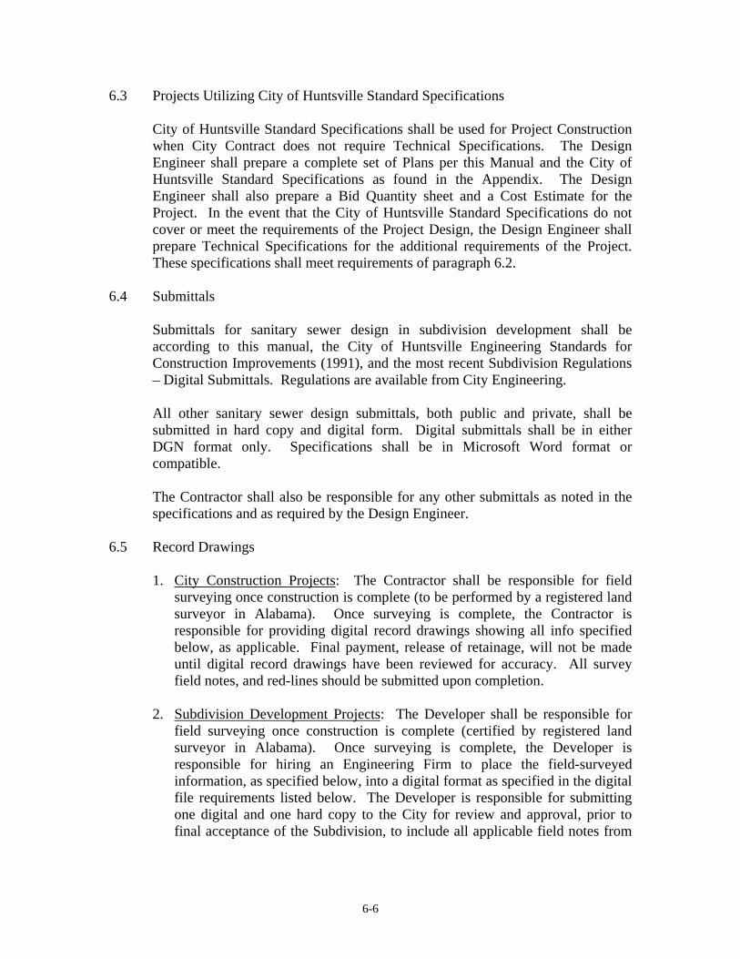
6.3 Projects Utilizing City of Huntsville Standard Specifications
City of Huntsville Standard Specifications shall be used for Project Construction when City Contract does not require Technical Specifications. The Design Engineer shall prepare a complete set of Plans per this Manual and the City of Huntsville Standard Specifications as found in the Appendix. The Design Engineer shall also prepare a Bid Quantity sheet and a Cost Estimate for the Project. In the event that the City of Huntsville Standard Specifications do not cover or meet the requirements of the Project Design, the Design Engineer shall prepare Technical Specifications for the additional requirements of the Project. These specifications shall meet requirements of paragraph 6.2.
6.4 Submittals
Submittals for sanitary sewer design in subdivision development shall be according to this manual, the City of Huntsville Engineering Standards for Construction Improvements (1991), and the most recent Subdivision Regulations – Digital Submittals. Regulations are available from City Engineering. All other sanitary sewer design submittals, both public and private, shall be submitted in hard copy and digital form. Digital submittals shall be in either DGN format only. Specifications shall be in Microsoft Word format or compatible. The Contractor shall also be responsible for any other submittals as noted in the specifications and as required by the Design Engineer.
6.5 Record Drawings 1. City Construction Projects: The Contractor shall be responsible for field
surveying once construction is complete (to be performed by a registered land surveyor in Alabama). Once surveying is complete, the Contractor is responsible for providing digital record drawings showing all info specified below, as applicable. Final payment, release of retainage, will not be made until digital record drawings have been reviewed for accuracy. All survey field notes, and red-lines should be submitted upon completion.
2. Subdivision Development Projects: The Developer shall be responsible for
field surveying once construction is complete (certified by registered land surveyor in Alabama). Once surveying is complete, the Developer is responsible for hiring an Engineering Firm to place the field-surveyed information, as specified below, into a digital format as specified in the digital file requirements listed below. The Developer is responsible for submitting one digital and one hard copy to the City for review and approval, prior to final acceptance of the Subdivision, to include all applicable field notes from

6-7
land surveyor. Bonded improvements will need to be incorporated into the record drawings upon completion.
3. Format Requirements for all record drawing submittals: All drawings shall be
prepared in Micro Station .DGN format, unless otherwise approved by the City Engineer. Transmittal letters shall consist of a list of files being submitted, a description of the data in each file, and a level/layer schematic of each design file. DGN design files should have working units as follows: master units in feet, no sub-units, and 1,000 positional units. All data submitted should use NAD 1983 Alabama East Zone coordinates as described in The Code of Alabama (1975), section 35-2-1 and NGVD 1988. Digital files shall be submitted on 4-3/4” CD ROM, 100 MB zip drive, 3 and ½ inch floppy disk, or to the City of Huntsville F.T. P. Site. Engineering Firm/Developer required to certify that record drawings are in the correct format upon submittal.
4. Record Drawing Guidelines, unless otherwise noted by City Engineer:
a. Gravity Line i. Horizontal Location of Manholes – Northing, and Easting
Coordinates ii. Vertical Location of Manholes – Lid elevation and Invert
elevation. iii. Location of service lateral connection to main line. iv. Changes in length, slope, size, or material of lines.
b. Force Mains
i. Horizontal Location of Air Relief/Vacuum/Isolation Valves – Northing and Easting Coordinates
ii. Horizontal and Vertical Location of Fittings/Bends iii. Changes in length, size, depth or material of lines iv. Changes in restraint types
c. Pump Stations
i. Changes in Structural Requirements – (length, width, thickness, cover, laps, bar size, spacing, materials, etc.)
ii. Changes in Site Development and/or Landscaping iii. Changes in Equipment
5. Record drawings must be submitted and approved prior to acceptance of the
sewers into the public system.

6-8
6. Record Drawing Certification: The Design Engineer shall certify record drawings. The following statement shall be added to the cover sheet of the record drawings and signed by the Design Engineer.
RECORD DRAWING CERTIFICATION: Based upon the provided survey and construction information, I, the Design Engineer, certify that I have reviewed the information provided to me on this project and determined that this project as constructed will convey the Design Flows as intended during the design phase. No guarantees or warranties are implied on the quality of construction. Signed:
Company: Date:

6-9
FIGURE 6.1 SAMPLE PLAN SET
(Following Page)
NOTICE: This sample plan set is shown to display the minimum layout requirements and sheet requirements. It is in no way considered a complete set of plans for a project. All sanitary sewer design projects shall contain a minimum of 4-5 sheets depending on the size and scope of the projects. All finished drawings and plans should contain the appropriate standard details and shall be referenced thoroughly throughout the entire drawing set. It is the responsibility of the Design Engineer to ensure the plans are complete and workable.


7-1
SECTION 7.0 CONSTRUCTION ADMINISTRATION 7.1 General
1. City of Huntsville Projects: The following general requirements apply to consultants hired by the City of Huntsville to perform construction administration or resident inspection.
• For SRF projects, the Contractor shall comply with the Equal Employment Opportunity, Minority Business Enterprises and Woman Business Enterprises requirements as required by ADEM.
• The Contractor shall submit a work schedule based on either the “Critical
Path Method” or “Primavera System”, within ten calendar days after the “Notice-to-proceed” is issued.
• During construction, material sampling and testing shall be required for
concrete and backfill.
• The inspector shall insure that the contractor performs required testing of gravity sewer lines and manholes.
• Pipe and fittings shall be handled and stored according to manufacturer’s
recommendations and the City of Huntsville Sanitary Sewer Specifications. This applies to all other materials used during construction.
• Project closeout requirements shall be clearly defined in the Contract
documents.
• Line and grade of gravity sanitary sewers shall be verified prior to backfill.
• All other Construction Administration responsibilities as specified in
contract between the City of Huntsville and Engineer.
2. Development Projects: The following general requirements apply to construction administration performed for private development projects within the City of Huntsville.
• Pipe and fittings shall be handled and stored according to manufacturer’s
recommendations and the City of Huntsville Sanitary Sewer

7-2
Specifications. This applies to all other materials used during construction.
• The Design Engineer shall insure that the contractor performs required
testing of gravity sewer lines and manholes.
• Line and grade of gravity sanitary sewers shall be surveyed by a Licensed Surveyor and verified by the Design Engineer for accuracy prior to sub-grade testing.
• Developer must submit certified record drawings to City Engineering.
Refer to Section 6, Paragraph 6.5. 7.2 Field Testing
Field testing of construction shall be conducted according to the City of Huntsville Sanitary Sewer Construction Specifications (See Section 4) and any additional specifications set forth by the Design Engineer. The City Construction Inspector or other City Representative and a Water Pollution Control representative shall be present during all field testing procedures as discussed throughout this manual. The City of Huntsville Standard Specifications are included in the Appendix.

8-1
SECTION 8.0 CHECKLISTS A checklist is provided on the following page for submittal purposes. This will allow for a quick review of remaining tasks. At each submittal the designer shall check “yes” for items that have been completed and “no” for those not completed. There is also a column for not applicable items and a column for comments. After completion, the checklist shall be submitted to the City Engineer with the appropriate contract documents. This checklist is available in digital format (Microsoft Excel).

City Project Number:
Engineer: Sheet #:
Project Name: Percent Submittal:
Project Number: Submittal Date:
ITEM YES NO N/A COMMENTS ITEM YES NO N/A COMMENTSCalculations: Calculation Sheet Submitted Calculation Sheet Approved
Plans: Specifications:Bench Marks & Datum Shown Engineer's Seal & SignatureConcrete Encasement SRF Documents IncludedDeed Book and Page Number City Specifications ReferencedDrop Inlets labeled Geotechnical Report AppendedEasement Plats Existing Utility Lines Shown (i.e. electric, gas, sewer, storm drains, telephone, water) Engineer's Seal & Signature Existing Ground Labeled Existing Utility Crossings Flow Arrows House/Lot No.
Sanitary Sewer Plans Review ChecklistCity of Huntsville, Alabama
FIGURE 8.1
Invert Elevations Labeled Legend Line Designation Location Map Lot Lines & Dimensions Manhole Exterior CoatingManhole Stations North Arrow Shown Pipe Type Labeled NAD 83 State Plane CoordinatesPlan DateProperty Owners, name & addressRailway Lines, existingResurfacing LimitsRight-of-Way, existingRim Elevation, manholeRock soundings/boringsScale/Graphic ScaleSewer GradesSewer SizesStandard NotesStation EquationsStationing Street NamesStream CrossingsStubsSurveyor's Seal & SignatureSurveyor's CertificationTitle Block/SheetTopo., existingTunnels/Bores/Sections

Appendix A
APPENDIX A MISCELLANEOUS FLOW DATA & CHARTS
TABLE OF CONTENTS
TABLE A-1 DESIGN BASIS FOR WASTEWATER FLOWS OF NEW SEWAGE WORKS TABLE A-2 DEVELOPED AREA WASTEWATER FLOWS

TABLE A-1DESIGN BASIS FOR WASTEWATER FLOWS OF NEW SEWAGE WORKS
DISCHARGE FACILITY DESIGN UNITSFLOW* (GPD)
FLOW DURATION (HOUR)
Dwellings per person 100 24Schools with showers and cafeteria per person 16 8Schools without showers and cafeteria per person 12 8Boarding Schools per person 75 16Motels at 65 gallons/person (rooms only) per person 130 16Trailer courts at 3 persons/trailer per trailer 225 24Restaurants per seat 40 16Interstate or through highway restaurants per seat 180 16Interstate rest areas per person 5 24Service Stations per vehicle serviced 10 16Factories per person per 8-hr shift 25 Operating PeriodShopping Centers (no food) per 1,000 SF of ultimate floor 150 12Hospitals per bed 300 24Nursing Home (add 75 gallons for laundry) per bed 120 24Homes for the Aged per bed 60 24Child Care Center per child and adult 10 Operating PeriodLaundromats, 9 to 12 machines per machines 250 16Swimming Pools per swimmer 10 12Theaters, Auditorium type per seat 5 12Picnic Areas per person 5 12Resort Camps, day and night with limited plumbing per campsite 50 24Luxury Camps with flush toilets per campsite 100 24Churches, no kitchens per seat 3 Operating Period
*Includes normal infiltration
Note: In all cases, use actual data from similar facilities when possible. Note variations due to factors such as age, water conservation, etc. Submit all design data used.
Source: City of Huntsville, City Engineer, Engineering Standards For Construction of Public Improvements, 1991.
A-1

TABLE A-2DEVELOPED AREA WASTEWATER FLOWS
DEVELOPMENTPOPULATION
PER UNITAVERAGE
(GALLON/UNIT/DAY)Single Family Dwelling 4 400Two Family Dwelling 8 8001 Bedroom Apartment 2 2002 Bedroom Apartment 3 3003 Bedroom Apartment 4 400Motel Rooms 2 200
DEVELOPMENT UNITEQUIVALENT
POPULATION PER UNITAVERAGE
(GALLON/UNIT/DAY)Schools* Students 0.15 15Mobile Homes Persons 2.00 200Nursing Homes Bed 1.00 100Offices Employee 0.15 15Laundromats Washer 4.00 400Non-developable Land Acres 1.00 100Commercial* Acres 20.00 2000Industrial* Acres 10.00 1000
*Actual measured wastewater flows should be used when available with allowance for futureexpansion. In addition, refer to flow rate values as presented in the City of HuntsvilleMaster Sewer Plan according to Service Area.
Source: Louisville and Jefferson County Metropolitan Sewer District Design Manual
A-2

Appendix B
APPENDIX B CITY OF HUNTSVILLE STANDARD DETAILS
TABLE OF CONTENTS
SD-1 ............................. Standard Sanitary Sewer Manhole Detail SD-2 ............................. Standard Sanitary Sewer Manhole Eccentric Top Section Detail SD-3 ............................. Standard Sanitary Sewer Manhole Frame and Cover Detail SD-4 ............................. Watertight Manhole Frame and Cover Detail SD-5 ............................. Precast Manhole Riser Joint SD-6 ............................. Standard Sanitary Sewer Manhole Step Detail SD-7 ............................. Flexible Pipe-To-Manhole Connector Detail SD-8A ........................... Sanitary Sewer Manhole Drop Connection Detail 12” Pipe and Larger SD-8B ........................... Sanitary Sewer Manhole Drop Connection Detail Pipe sizes 10” and Smaller SD-9 ............................. Bedding and Backfill Requirements Around Manholes in Non-Traffic
Areas SD-10A ......................... Option No. 1 - Bedding and Backfill Requirements in Around Manholes
in Traffic Areas SD-10B ......................... Option No. 2 - Bedding and Backfill Requirements in Around Manholes
in Traffic Areas SD-11 ........................... New Manhole Connection Detail SD-12 ........................... Abandonment of Existing Manhole and Line Detail SD-13 ........................... Manhole Venting Detail SD-14A ......................... Typical Trench Detail for Pipe in Non-Traffic Areas SD-14B ......................... Typical Trench Detail for Pipe in Non-Traffic Areas SD-15A ......................... Option No.1 - Typical Trench Detail for Pipe in Traffic Areas SD-15B ......................... Option No.2 - Typical Trench Detail for Pipe in Traffic Areas SD-15C ......................... Option No.3 - Typical Trench Detail for Pipe in Traffic Areas SD-16 ........................... Utility Crossing Details SD-17 ........................... Pipe Encasement Details for Borings SD-18 ........................... (Shallow Creek Crossing) Concrete Encasement with Control Joint
Detail SD-19A ......................... Creek Crossing in Earth or Loose Rock SD-19B ......................... Creek Crossing in Earth or Loose Rock SD-20A ......................... Above Creek Crossing Detail SD-20B ......................... Above Creek Crossing Support Detail SD-21A ......................... Service Connection Details for Deep Sewer (More Than 6’) SD-21B ......................... Service Connection Details for Shallow Sewer (Less Than 6’) SD-22A ......................... Oil, Water, and Grease Separation Detail SD-22B ......................... Grease Interceptor Inlet Sanitary Sewer Tee Detail SD-22C ......................... Grease Interceptor Outlet Sanitary Sewer Tee Detail SD-23 ........................... Flat Top Manhole Vent Detail SD-24 ........................... Manhole Invert Detail SD-25 ........................... Tee Wye Detail

5"5"
16"
TYP.
STANDARD SANITARY SEWER MANHOLE DETAILNOT TO SCALE
2’ MIN.
4’ MAX.
1’- 4"
2’- 8"
TYPICAL SECTION
CLASS "A" CONCRETE
PRE-CAST CONC. BASE
5" TYP.
8" ALL AROUND
NOTE: CONCRETE SHALL BE 4000 PSI
(28 DAY COMPRESSIVE STRENGTH)
SEE SANITARY SEWER MANHOLE
FRAME AND COVER DETAIL.
SEE SANITARY
SEWER MANHOLE
STEP DETAIL.
SEE PRECAST MH RISERJOINTS DETAIL.
FINISHED GRADE
CITY OF HUNTSVILLE, ALABAMA
CITY OF HUNTSVILLE
STANDARD SANITARY SEWER
MANHOLE DETAIL
SD-1
SEE FLEXIBLE
PIPE-TO-MANHOLE
CONNECTOR DETAIL
2’-2 3/4"
MIN.
NOTE: ADDITIONAL RISER SECTIONS
CAN BE ADDED AS NEEDED
VARIABLE
TO 4’-0"
BENCH SLOPESHALL BE 1" PER FOOT
6"
SEE STANDARD
SANITARY SEWER
MANHOLE ECCENTRIC
TOP SECTION DETAIL.
PRECAST CONCRETE
ADJUSTING RINGS
(MAX. OF 3 OR 12 IN.),
(BRICKS WILL NOT
BE ALLOWED)
4’- 0"
MIN.
ALDOT #78
CRUSHED STONE6" MIN. IN STABLE SOIL,12" MIN. IN ROCK ORUNSTABLE, SOFT SOIL
(BASE SECTION FOR 6" - 24" PIPE SHOWN; LARGER PIPES NOVEMBER REQUIRE
LARGER MANHOLE. CONSULT MANHOLE MANUFACTURER FOR DETAILS)
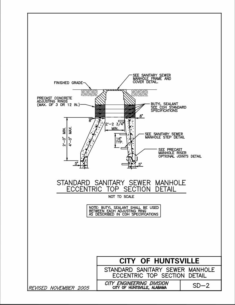
NOT TO SCALE
8"
8"
5" 5"
16"
TYP.
STANDARD SANITARY SEWER MANHOLE
ECCENTRIC TOP SECTION DETAIL
4’-0
" M
AX
.
2’-0" M
IN
.
STANDARD SANITARY SEWER MANHOLE
ECCENTRIC TOP SECTION DETAIL
SD-2
FINISHED GRADE
CITY OF HUNTSVILLE, ALABAMA
CITY OF HUNTSVILLE
SEE PRECAST
MANHOLE RISER
OPTIONAL JOINTS DETAIL
SEE SANITARY SEWER
MANHOLE FRAME AND
COVER DETAIL.
2’-2 3/4"
MIN.
NOTE: BUTYL SEALANT SHALL BE USED
BETWEEN EACH ADJUSTING RING
AS DESCRIBED IN COH SPECIFICATIONS
PRECAST CONCRETE
ADJUSTING RINGS
(MAX. OF 3 OR 12 IN.) BUTYL SEALANT
SEE COH STANDARD
SPECIFICATIONS
SEE SANITARY SEWER
MANHOLE STEP DETAIL

COH MASTER DETAILS 042009.dgn 5/13/2010 3:05:30 PM justin.marsh

COH MASTER DETAILS 042009.dgn 5/13/2010 3:02:35 PM justin.marsh

NOT TO SCALE
SD-5CITY OF HUNTSVILLE, ALABAMA
CITY OF HUNTSVILLE
PRECAST MANHOLE RISER JOINT
PRECAST MANHOLE RISER JOINT
NOTE:
ALL JOINTS SHALL BE OF SUCH DESIGN
AS WILL PERMIT EFFECTIVE JOINING WITH
NO LEAKAGE AND NO INFILTRATION AND TO
PERMIT PLACEMENT WITHOUT APPRECIABLE
IRREGULARITIES ON THE INTERIOR WALL.
HAMILTON KENT
PRE-LUBRICATED
MANHOLE RUBBER GASKET
OR APPROVED EQUAL
BUTYL SEALANT,
CONSEAL CS-231
OR APPROVED EQUAL
DOUBLE SEAL METHOD
HAMILTON KENT RUBBER GASKET
AND CONSEAL CS-231-BUTYL SEALANT

1 1/8 "3 3/8 "
9 1/8 "1 1/4 "
10 3/4 "
12"
5 3/4 "
POLYPROPYLENE PLASTIC
NOTE:
NOT TO SCALE
STANDARD SANITARY SEWER MANHOLE STEP DETAIL
STANDARD SANITARY SEWER
MANHOLE STEP DETAIL
SD-6CITY OF HUNTSVILLE, ALABAMA
CITY OF HUNTSVILLE
1/2 " GRADE 60
STEEL REINFORCEMENT
MANHOLE STEPS SHALL BE MANUFACTURED FROM POLYPROPYLENE PLASTIC
REINFORCED WITH A 1/2 " GRADE 60 STEEL ROD. STEPS SHALL BE EMBEDDED
IN THE RISER, BASE AND TOP SECTIONS A MINIMUM OF 3" AT THE TIME OF CONSTRUCTION.
MANHOLE STEPS SHALL BE A MINIMUM OF 10 3/4 " WIDE AND EXTEND FROM THE MANHOLE
WALL A MINIMUM OF 5 3/4 ".


NOT TO SCALE
MA
NH
OL
E O
R O
TH
ER
ST
RU
CT
UR
E
6" MIN. IN STABLE SOIL,12" MIN. IN ROCK ORUNSTABLE, SOFT SOIL
PIPEPIPE
3’
FINISHED GRADE
COMPACT THIS PORTION OF
TRENCH WITH HAND HELD
MECHANICAL TAMPERS
92% STANDARD PROCTOR
DENSITY
BEDDING AND BACKFILL REQUIREMENTS
AROUND MANHOLES AND OTHER DRAINAGE
& SANITARY SEWER STRUCTURES
IN NON-TRAFFIC AREAS
SD-9
BACKFILL AS REQUIRED
BY TYPICAL TRENCH
DETAILS FOR PIPE
CITY OF HUNTSVILLE, ALABAMA
CITY OF HUNTSVILLE
COMPACTED SOIL
IN 12" LAYERS TO
92% STANDARD
PROCTOR DENSITY
ALDOT #78
CRUSHED STONE
BEDDING AND BACKFILL REQUIREMENTS
AROUND MANHOLES IN NON-TRAFFIC AREAS

CITY OF HUNTSVILLE, ALABAMA
CITY OF HUNTSVILLE
SD-10A
NOT TO SCALE
MA
NH
OL
E O
R O
TH
ER
ST
RU
CT
UR
E
6" MIN. IN STABLE SOIL,12" MIN. IN ROCK OR
PIPE
ALDOT #78 CRUSHED STONE
UNSTABLE, SOFT SOIL(TYPICAL ALL SIDES)
DENSE GRADED BASE
MATERIAL AS REQUIRED
BY STREET SECTION
(TYPICAL ALL SIDES)
DENSE GRADED BASE
MATERIAL AS REQUIRED
BY STREET SECTION
(TYPICAL ALL SIDES)
PIPE
(OPTION NO. 1)
BEDDING AND BACKFILL REQUIREMENTS
AROUND MANHOLES AND OTHER DRAINAGE
& SANITARY SEWER STRUCTURES
WITHIN TRAFFIC AREAS
OPTION NO. 1BEDDING AND BACKFILL REQUIREMENTSAROUND MANHOLES IN TRAFFIC AREAS
FINISHED PAVEMENT
(SEE NOTE BELOW)
12" MIN. DENSE
GRADED BASE MATERIAL
(TYPICAL ALL SIDES)
ALDOT #78 CRUSHEDSTONE, (TYPICALALL SIDES)
NOTE:
1. TRAFFIC AREAS SHALL EXTEND TO 5 FT BEYOND BACK OF CURB OR EDGE OF
PAVEMENT, UNLESS OTHERWISE NOTED ON PLAN VIEW.
2. ASPHALT PAVING FOR STREETS SHALL MEET CURRENT CITY REQUIREMENTS.

CITY OF HUNTSVILLE, ALABAMA
CITY OF HUNTSVILLE
SD-10B
NOT TO SCALE
MA
NH
OL
E O
R O
TH
ER
ST
RU
CT
UR
E
6" MIN. IN STABLE SOIL,12" MIN. IN ROCK OR
PIPE
ALDOT #78 CRUSHED STONE
PIPE
UNSTABLE, SOFT SOIL(TYPICAL ALL SIDES)
GEOTEXTILE
FILTER FABRIC
COMPACTED SOIL
IN 6" LAYERS TO
95% STANDARD
PROCTOR DENSITY
DENSE GRADED BASE
MATERIAL AS REQUIRED
BY STREET SECTION
(TYPICAL ALL SIDES)
(OPTION NO. 2)
BEDDING AND BACKFILL REQUIREMENTS
AROUND MANHOLES AND OTHER DRAINAGE
& SANITARY SEWER STRUCTURES
WITHIN TRAFFIC AREAS
OPTION NO. 2BEDDING AND BACKFILL REQUIREMENTSAROUND MANHOLES IN TRAFFIC AREAS
NOTE:
(SOIL BACKFILL OPTION ONLY TO BE USED ON TRENCHES GREATER THAN 15 FEET DEEP)
FINISHED PAVEMENT
(SEE NOTE BELOW)
PAVEMENT SUBGRADE
TOP 6" COMPACTED
TO 100% STANDARD
PROCTOR DENSITY
(TYPICAL ALL SIDES)
BACKFILL AS REQUIRED
BY TYPICAL TRENCH
DETAIL FOR PIPE
NOTE:
1. TRAFFIC AREAS SHALL EXTEND TO 5 FT BEYOND BACK OF CURB OR EDGE OF
PAVEMENT, UNLESS OTHERWISE NOTED ON PLAN VIEW.
2. ASPHALT PAVING FOR STREETS SHALL MEET CURRENT CITY REQUIREMENTS.
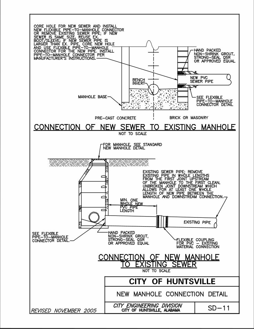
MANHOLE BASE
NOT TO SCALE
PRE-CAST CONCRETE BRICK OR MASONRY
CONNECTION OF NEW SEWER TO EXISTING MANHOLE
EXISTING SEWER PIPE; REMOVE
EXISTING PIPE IN WHOLE LENGTHS
FROM THE FIRST JOINT UPSTREAM
OF THE MANHOLE TO THE FIRST CLEAN,
UNBROKEN JOINT DOWNSTREAM WHICH
ALLOWS FOR AT LEAST ONE WHOLE
LENGTH OF NEW PIPE BETWEEN THE
MANHOLE AND DOWNSTREAM CONNECTION.
NOT TO SCALE
MIN. ONEWHOLE NEW PVC PIPELENGTH
EXISTING PIPE
FLEXIBLE COUPLING
FOR PVC - EXISTING
MATERIAL CONNECTION
FOR MANHOLE, SEE STANDARD
NEW MANHOLE DETAIL
CONNECTION OF NEW MANHOLE
TO EXISTING SEWER
NEW MANHOLE CONNECTION DETAIL
BENCH
INVERT
CITY OF HUNTSVILLE, ALABAMA
CITY OF HUNTSVILLE
SD-11
CORE HOLE FOR NEW SEWER AND INSTALL
NEW FLEXIBLE PIPE-TO-MANHOLE CONNECTOR
OR REMOVE EXISTING SEWER PIPE; IF NEW
SEWER IS SAME SIZE, REUSE EX.
BOOT/SLEEVE; IF NEW SEWER PIPE IS
LARGER THAN EX. PIPE, CORE NEW HOLE
AND USE FLEXIBLE PIPE-TO-MANHOLE
CONNECTOR FOR THE NEW PIPE. INSTALL
PIPE-TO-MANHOLE CONNECTOR PER
MANUFACTURER’S INSTRUCTIONS.
SEE FLEXIBLE
PIPE-TO-MANHOLE
CONNECTOR DETAIL
SEE FLEXIBLE
PIPE-TO-MANHOLE
CONNECTOR DETAIL.
HAND PACKED
NON-SHRINK GROUT,
STRONG-SEAL QSR
OR APPROVED EQUAL
HAND PACKED
NON-SHRINK GROUT,
STRONG-SEAL QSR
OR APPROVED EQUAL
NEW PVC
SEWER PIPE

FINISHED GRADE
REMOVE EXISTING
CONE SECTION
GROUT/FILL EXISTING
PIPE FOR MIN. OF 12"
12" MIN.
EXISTING LINE
TO BE ABANDONED
3’ MIN.
ABANDONMENT OF EXISTING
MANHOLE AND LINE DETAIL
CITY OF HUNTSVILLE, ALABAMA
CITY OF HUNTSVILLE
SD-12
NOT TO SCALE
EARTH BACKFILL
(FREE OF LARGE
ROCKS) IN NON-
TRAFFIC AREAS
TO BE COMPACTED
AS PER SPECS.
ALDOT #78
CRUSHED STONE
OR FLOWABLE FILL
IN TRAFFIC AREAS
AS PER SPECS.
FILL EXISTING
MANHOLE
WITH CRUSHED
ROCK
GROUT/FILL
EXISTING
PIPE FOR
MIN. OF 12"
REMOVE EXISTING
MANHOLE FRAME
& COVER AND RETURN
TO THE CITY
OF HUNTSVILLE
ABANDONMENT OF
EXISTING MANHOLE AND LINE
12" MIN.
CONCRETE
FILL/CAP
NOTE: FLOWABLE FILL NOVEMBER BE USED IN LIEU
OF GROUT/FILL AND CRUSHED ROCK
WHEN APPLICABLE.


CL
PIPE
12"MIN.
EARTH BACKFILL (FREE OF
LARGE ROCKS) TO BE COMPACTED
NOT TO SCALE
FINISHED GRADE
COMPACT THIS PORTION OF
TRENCH WITH HAND HELD
MECHANICAL TAMPERS
IN 12" LAYERS TO 92%
6" MIN. IN STABLE SOIL,
12" MIN. IN ROCK OR
UNSTABLE, SOFT SOIL
STANDARD PROCTOR DENSITY
EACH
SIDE
ALDOT #78 CRUSHED STONE OR SELECT
BACKFILL APPROVED BY THE INSPECTOR
ALDOT #78 CRUSHED STONE
3’ MIN.
TYPICAL TRENCH DETAIL
FOR PIPE IN NON-TRAFFIC AREAS
CITY OF HUNTSVILLE, ALABAMA
CITY OF HUNTSVILLE
SD-14A
NOTE: ALL EXCAVATION WORK SHALL BE IN COMPLIANCE
WITH APPLICABLE REQUIREMENTS OF GOVERNING
AUTHORITIES HAVING JURISDICTION
TYPICAL TRENCH DETAIL FORDUCTILE IRON SANITARY SEWER PIPE
IN NON-TRAFFIC AREA
BACKFILL IN WETLAND AREAS SHALL
BE RESTORED TO ORIGINAL GRADE;
IN ALL OTHER AREAS BACKFILL TO BE
MOUNDED TO ALLOW FOR SETTLEMENT.
D

CL
PIPE
12"MIN.
12"
MIN.
EARTH BACKFILL (FREE OFLARGE ROCKS) TO BE COMPACTED
NOT TO SCALE
FINISHED GRADE
COMPACT THIS PORTION OFTRENCH WITH HAND HELD
IN 12" LAYERS TO 92%
ALDOT #78 CRUSHED STONE
6" MIN. IN STABLE SOIL,
12" MIN. IN ROCK OR
UNSTABLE, SOFT SOIL
STANDARD PROCTOR DENSITY
EACH
SIDE
ALDOT #78 CRUSHED STONE
NOTE: ALL EXCAVATION WORK SHALL BE IN COMPLIANCE
WITH APPLICABLE REQUIREMENTS OF GOVERNING
AUTHORITIES HAVING JURISDICTION
TYPICAL TRENCH DETAIL
FOR PIPE IN NON-TRAFFIC AREAS
CITY OF HUNTSVILLE, ALABAMA
CITY OF HUNTSVILLE
SD-14B
3’ MIN.
TYPICAL TRENCH DETAIL FORRCP & PVC SANITARY SEWER PIPE
IN NON-TRAFFIC AREA
BACKFILL IN WETLAND AREAS SHALL
BE RESTORED TO ORIGINAL GRADE;
IN ALL OTHER AREAS BACKFILL TO BE
MOUNDED TO ALLOW FOR SETTLEMENT.
D
MECHANICAL TAMPERS 2’ ABOVE
CRUSHED STONE

CL
PIPE
12"MIN.
6" MIN. IN STABLE SOIL,
12" MIN. IN ROCK OR
UNSTABLE, SOFT SOIL
EACH
SIDE
FINISHED PAVEMENT
ALDOT #78 CRUSHED STONE
NOT TO SCALE
2’
3’ MIN.
CITY OF HUNTSVILLE, ALABAMA
CITY OF HUNTSVILLE
SD-15A
NOTES:
1.
2.
ALDOT #78 CRUSHED STONE
ASPHALT PAVING: SEE NOTE BELOW.
3.
4.
OPTION NO. 1TYPICAL TRENCH DETAILS
FOR PIPE IN TRAFFIC AREAS
DENSE GRADED BASE MATERIAL
AS REQUIRED BY STREET SECTION
12" MIN. DENSE
GRADED BASE MATERIAL
D
(OPTION NO. 1)
TYPICAL TRENCH DETAIL FOR
SANITARY SEWER PIPE
IN TRAFFIC AREAS
MAXIMUM
ALLOWABLE
TRENCH WIDTH
"W"
INSIDE
DIAMETER
OF PIPE
"D"
2’-6" 4"
2’-8"
2’-10"
3’-0"
3’-5"
3’-9"
4’-1"
BACKFILLLIMITS TABLE
4’-4"
4’-8"
5’-1"
5’-5"
5’-10"
6’-2"
6’-8"
6’-11"
7’-6"
D+2t+2’-8"
6"
8"
10"
12"
15"
18"
21"
24"
27"
30"
33"
36"
39"
42"
48"
OVER 48"
IF "W" IS EXCEEDED, THE CONTRACTOR
SHALL BE RESPONSIBLE FOR ADDITIONAL
COST OF CRUSHED STONE, UNLESS
OTHERWISE APPROVED BY CITY ENGINEERING.
SAW CUT 1’-0" MIN.
BEYOND TRENCH EXCAVATION
ALL EXCAVATION WORK SHALL BE IN COMPLIANCE
WITH APPLICABLE REQUIREMENTS OF GOVERNING
AUTHORITIES HAVING JURISDICTION.
TRAFFIC AREAS TO EXTEND 5 FT BEYOND BACK OF
CURB OR EDGE OF PAVEMENT, UNLESS OTHERWISE
NOTED ON PLAN VIEW.
ASPHALT PAVING FOR STREETS SHALL MEET CURRENT
CITY REQUIREMENTS.
STEEL ENCASEMENT SHALL BE USED UNDER ROADWAYS
WHERE SPECIFIED.

CL
PIPE
12"MIN.
6" MIN. IN STABLE SOIL,
12" MIN. IN ROCK OR
UNSTABLE, SOFT SOIL
EACH
SIDE
FINISHED PAVEMENT
ALDOT #78 CRUSHED STONE
NOT TO SCALE
CITY OF HUNTSVILLE, ALABAMA
CITY OF HUNTSVILLE
SD-15B
NOTES:
1.
2.
ASPHALT PAVING: SEE NOTE BELOW.
3.
4.
OPTION NO. 2TYPICAL TRENCH DETAILS
FOR PIPE IN TRAFFIC AREAS
(OPTION NO. 2)
TYPICAL TRENCH DETAIL FOR
SANITARY SEWER PIPE IN TRAFFIC AREAS
WITH TRENCH DEPTHS GREATER THAN 15 FEET
VARIES
1 FT. MIN.
GEOTEXTILE FILTER FABRIC
DENSE GRADED BASE MATERIAL
AS REQUIRED BY STREET SECTION
EARTH BACKFILL
(FREE OF LARGE ROCKS)
TO BE COMPACTED
IN 6" LAYERS TO 95%
STANDARD PROCTOR DENSITY
ALDOT #78
CRUSHED STONE
PAVEMENT SUBGRADE
TOP 6" COMPACTED T0 100%
STANDARD PROCTOR DENSITY
D
5.
SAW CUT 1’-0" MIN.
BEYOND TRENCH EXCAVATION
ALL EXCAVATION WORK SHALL BE IN COMPLIANCE
WITH APPLICABLE REQUIREMENTS OF GOVERNING
AUTHORITIES HAVING JURISDICTION.
TRAFFIC AREAS TO EXTEND 5 FT BEYOND BACK OF
CURB OR EDGE OF PAVEMENT, UNLESS OTHERWISE
NOTED ON PLAN VIEW.
ASPHALT PAVING FOR STREETS SHALL MEET CURRENT
CITY REQUIREMENTS.
STEEL ENCASEMENT SHALL BE USED UNDER ROADWAYS
WHERE SPECIFIED.
CONTRACTOR RESPONSIBLE FOR TESTING TO CERTIFY
MINIMUM COMPACTION REQUIREMENTS.

CL
PIPE
12"MIN.
6" MIN. IN STABLE SOIL,
12" MIN. IN ROCK OR
UNSTABLE, SOFT SOIL
EACH
SIDE
ALDOT #78 CRUSHED STONE
NOT TO SCALE
CITY OF HUNTSVILLE, ALABAMA
CITY OF HUNTSVILLE
SD-15C
NOTES:
1.
2.
ASPHALT PAVING: SEE NOTE BELOW.
3.
4.
OPTION NO. 3TYPICAL TRENCH DETAILS
FOR PIPE IN TRAFFIC AREAS
(OPTION NO. 3)
TYPICAL TRENCH DETAIL FOR
SANITARY SEWER PIPE IN TRAFFIC AREAS
WITH TRENCH DEPTHS GREATER THAN 15 FEET
VA
RIE
S
DENSE GRADED BASE MATERIAL
AS REQUIRED BY STREET SECTION
PAVEMENT SUBGRADE
TOP 6" COMPACTED T0 100%
STANDARD PROCTOR DENSITY
D
5.
CONTROLLED LOWSTRENGTH MATERIAL(CLSM)
FINISHED PAVEMENT
SAW CUT 1’-0" MIN.
BEYOND TRENCH EXCAVATION
ALL EXCAVATION WORK SHALL BE IN COMPLIANCE
WITH APPLICABLE REQUIREMENTS OF GOVERNING
AUTHORITIES HAVING JURISDICTION.
TRAFFIC AREAS TO EXTEND 5 FT BEYOND BACK OF
CURB OR EDGE OF PAVEMENT, UNLESS OTHERWISE
NOTED ON PLAN VIEW.
ASPHALT PAVING FOR STREETS SHALL MEET CURRENT
CITY REQUIREMENTS.
STEEL ENCASEMENT SHALL BE USED UNDER ROADWAYS
WHERE SPECIFIED.
CONTRACTOR RESPONSIBLE FOR TESTING TO CERTIFY
MINIMUM COMPACTION REQUIREMENTS.


6" M
IN
.
#4
’s @
12
" O
.C.
#4’s (
TY
P.)
SU
PP
OR
T P
IPE
ON
CO
NC
RE
TE
BL
OC
K
#4
’s @
12
" O
.C.
CO
NT
RO
L J
OIN
T
NO
TE
:
CO
NT
RO
L J
OIN
TS
AN
D P
IPE
JO
INT
S
FO
R E
NC
AS
EM
EN
T S
HA
LL
CO
INC
IDE
FO
R S
PA
CIN
G. M
AX
. D
IST
AN
CE
BE
TW
EE
N
CO
NT
RO
L J
OIN
TS
SH
AL
L B
E 2
4’.
CO
MP
AC
TE
D G
RA
NU
LA
R F
ILL
PL
AC
ED
BE
TW
EE
N C
ON
CR
ET
E
AN
D U
ND
IST
UR
BE
D E
AR
TH
SD-18
6"
MIN
.
6"
MIN
.
CITY OF HUNTSVILLE, ALABAMA
CITY OF HUNTSVILLE
CL
AS
S "
B"
(3
00
0 P
SI)
CO
NC
RE
TE
EN
CA
SE
ME
NT
(SH
AL
LO
W C
RE
EK
CR
OS
SIN
G)
CO
NC
RE
TE
EN
CA
SE
ME
NT
WIT
H C
ON
TR
OL
JO
INT
DE
TA
IL
(SHALLOW CREEK CROSSING)CONCRETE ENCASEMENT
WITH CONTROL JOINT DETAIL
NO
T T
O S
CA
LE
*3 F
T.
OR
LE
SS
* N
OT
E:
TH
IS
ME
TH
OD
OF
IN
ST
AL
LA
TIO
N N
OV
EM
BE
R A
LS
O
BE
NE
CE
SS
AR
Y O
N C
RE
EK
S/S
TR
EA
MS
WIT
H H
IG
H V
UL
NE
RA
BIL
IT
Y T
O E
RO
SIO
N.

EA. SIDE12" MIN. ONBOTT. AND6" MIN. ON6" MIN.
18"
36
" M
IN
.
12"
MIN.MIN.
FLOWLINE
TOP OF BANK
5’-0"5’-0"
PAY LIMITS
CREEK CROSSING IN
EARTH OR LOOSE ROCKNOT TO SCALE
SD-19A
CREEK CROSSING
IN EARTH OR LOOSE ROCK
CITY OF HUNTSVILLE, ALABAMA
CITY OF HUNTSVILLE
ALDOT #78
STONE BACKFILL
STONE BACKFILL
ALDOT #2
NATIVE MATERIAL
6"
ALDOT #78
STONE BACKFILL

NOT TO SCALE
EARTH OR LOOSE ROCK
18"
12"
PIP
E36"
O.D
.M
IN.
STREAM BED
MIN.O.D.MIN.
12"PIPE12"
CREEK CROSSING IN
SD-19B
CREEK CROSSING
IN EARTH OR LOOSE ROCK
CITY OF HUNTSVILLE, ALABAMA
CITY OF HUNTSVILLE
ALDOT #2
STONE
BACKFILL
TYPICAL SECTION
12" MIN.
NATIVE
SOILS
6"
6" MIN.
ALDOT #78
STONE
BACKFILL

20’
APPROX. 25’
STREAM BED
NOT TO SCALE
SECTION
ABOVE CREEK CROSSING DETAIL
PLAN
1’ MIN.DEPTH
TO
E O
F
BA
NK
(T
YP
)
TO
P O
F
BA
NK
(T
YP
)
ABOVE CREEK CROSSING DETAIL
2’
24"MIN.
SD-20ACITY OF HUNTSVILLE, ALABAMA
CITY OF HUNTSVILLE
CONCRETEPIER
EXIST.GRADE
DUCTILE IRON PIPE
NOTES:
1. DUCTILE IRON PIPE (DIP) SHALL BE AS SPECIFIED IN SPEC. SECTION 645.
2. LONG-SPAN DIP SHALL BE USED TO REDUCE THE NUMBERS OF PIERS REQUIRED IN CREEK.
RIPRAPAS SPECIFIEDTYPICALEACH SIDE
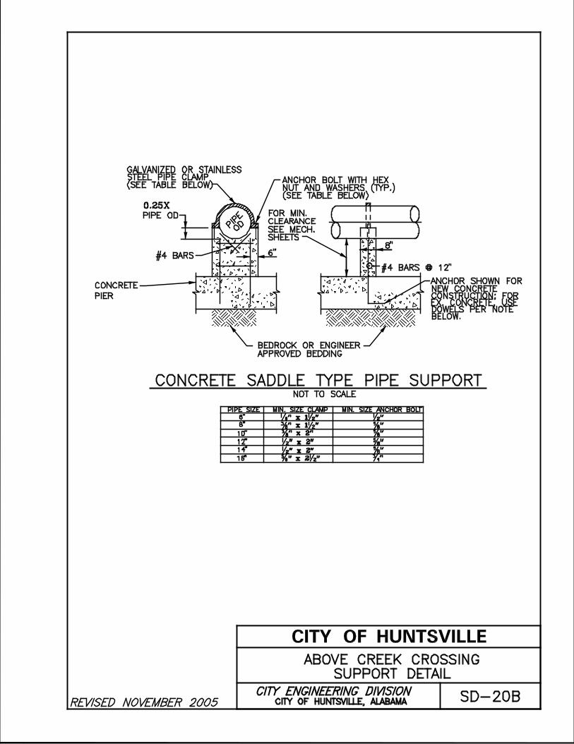
#4 BARS @ 12"
8"6"#4 BARS
PIP
E
OD
ANCHOR SHOWN FORNEW CONCRETECONSTRUCTION; FOREX. CONCRETE, USE
ANCHOR BOLT WITH HEXNUT AND WASHERS (TYP.)(SEE TABLE BELOW)
GALVANIZED OR STAINLESSSTEEL PIPE CLAMP(SEE TABLE BELOW)
PIPE SIZE
6"
8"
10"
12"
14"
16"
1/8 " x 1 1/2 "
3/8 " x 1 1/2 "
3/8 " x 2"
1/2 " x 2"
5/8 " x 2 1/2 "
1/2 " x 2"
1/2 "
5/8 "
5/8 "
5/8 "
5/8 "
3/4 "
NOT TO SCALE
CONCRETE SADDLE TYPE PIPE SUPPORT
DOWELS PER NOTEBELOW.
FOR MIN.
CLEARANCE
SEE MECH.
SHEETS
MIN. SIZE CLAMP MIN. SIZE ANCHOR BOLT
SD-20BCITY OF HUNTSVILLE, ALABAMA
CITY OF HUNTSVILLE
CONCRETE
PIER
PIPE OD
ABOVE CREEK CROSSING
SUPPORT DETAIL
0.25X
BEDROCK OR ENGINEER
APPROVED BEDDING


Appendix C
APPENDIX C CITY OF HUNTSVILLE STANDARD SPECIFICATIONS
TABLE OF CONTENTS
Section 125 – Measurement and Payment
Section 202 – Excavating, Backfilling, and Compacting for Sanitary Sewers
Section 203 – Rock Removal
Section 204 – Subsurface Investigation
Section 644 – Dewatering
Section 645 – Sanitary Sewers
Section 646 – Manholes for Sanitary Sewers
Section 647 – Television Inspection of Sewers
Section 648 – Maintaining Wastewater Flow

DIVISION 100 – GENERAL CONDITIONS
SECTION 125 MEASUREMENT AND PAYMENT
125.01 BASIS OF PAYMENT
A. General
1. The “Owner” shall refer to the City of Huntsville’s Engineering Department and/or Water Pollution Control. The Owner’s Representative” shall refer to the Design Engineer.
2. Contractor shall be responsible to repair any damage to those items not designated
for demolition or removal in a manner satisfactory to the Owner at no additional cost to the Owner.
3. The Owner reserves the right to make reasonable changes in line locations without
extra cost, except as may be determined by extra units of materials and construction actually involved.
4. At completion of project, deliver record documents and plan view drawing to Owner.
Record Drawings must be submitted and approved prior to acceptance of the sewers into the public system. APPROVAL FOR FINAL PAYMENT WILL BE CONTINGENT UPON COMPLIANCE WITH THESE PROVISIONS.
B. Subsurface Investigation
1. No separate pay item shall be included for subsurface investigation. Test borings and
other exploratory operations conducted by the Contractor will be at no cost to the Owner.
C. Excavation
1. All excavation of materials shall be included in the unit bid price for the sanitary sewer pipe, unless otherwise specified on the Plans or in the bid proposal.
2. All excavation will be unclassified and no additional payment will be made
regardless of type of material encountered unless provisions were made in bid documents.
3. Unauthorized excavation, as well as remedial work directed by the Owner or the
Owner’s Representative, shall be at Contractor's expense.
DIVISION 100 – GENERAL CONDITIONS
4. No compensation will be allowed for additional excavation necessary for establishing stable subgrade; it shall be included in the unit bid price.
5. Dispose of excess soil material and waste materials in a legal manner per the
Owner’s direction at no additional cost to the Owner.
6. Pavement shall be sawcut without extra compensation to the Contractor.
7. Sheeting and shoring of trenches shall be provided at the Contractor’s expense. In the event the Owner directs the Contractor to leave shoring materials in place, the Owner will reimburse the Contractor for the reasonable cost of leaving such materials in place.
8. Should the lack of a solid vertical excavation face occur due to improper trench
excavation, the entire cost of furnishing and installing metal harness anchorages in excess of the Contract value of the contract blocking replaced by such anchorages shall be borne by the Contractor.
D. Rock Removal
1. If provisions are made in the bid for rock excavation, rock excavation shall be paid for. Otherwise, all excavation of any nature shall be unclassified and payment for the same shall be included in the unit price of other items of work.
E. Dewatering
1. Dewatering of all excavations shall be the responsibility of the Contractor, and no additional compensation shall be allowed. The presence of groundwater and surface water should be accounted for in the base bid price.

DIVISION 100 – GENERAL CONDITIONS
F. Pressure Sewer Main
1. Measurement shall be on the basis of lineal foot along the centerline of the pipe (excluding fittings and valves) with deductions only for structures such as pump stations, meter vaults, and other structures of similar nature.
Payment shall be as specified below:
* inch Type Sanitary Sewer Pipe, Class ** - per Linear Foot.
Accepted Types are as Follows:
Ductile Iron (DIP) Polyvinyl Chloride (PVC) Reinforced Concrete (RCP)
* Denotes Pipe Size ** Denotes Class of Pipe
2. Work under these items includes, but is not limited to, trenching, bedding,
backfilling, solid rock removal, hauling and disposal of bedding and waste material, unpaved surface restoration, repair or replacement of fences, pressure testing, cleanup, seeding, and any work included in the Contract not covered by other items on the Bid Form.
3. Payment for fittings is not included in this pay item.
4. Copper tracer wire or metallic tape is not included in this pay item and will be paid
for separately as shown on Drawings.
G. Gravity Sewer Main
1. Payment for gravity sewer lines will be made at the contract unit price per linear foot in place, with deductions for manholes, and shall include compensation for furnishing pipe, trenching (including rock excavation), Class I bedding material, laying, jointing, temporary trench shoring, sheeting and bracing, initial backfill of Class I material over top of pipe, and all other appurtenances required but not specifically delineated herein.
2. The quantity of sewer to be paid for shall be the length of pipe measured along the
centerline of the completed pipelines without deducting the length of branches and fittings to the center of the manhole.

DIVISION 100 – GENERAL CONDITIONS
3. Payment for final backfill shall be included in this pay item including Class II material (DGA) and bituminous binder material required in restoration of paved areas. Class II material and bituminous binder shall be included in this pay item and is considered incidental to the installation of the gravity sewer main.
4. Payment for concrete sidewalk replacement, including compensation for compacting,
Class I material, furnishing and installing concrete to a minimum strength and thickness as specified in the entire area of existing concrete sidewalk disturbed during construction is considered incidental to the installation of the gravity sewer main.
5. Payment for this item shall include the testing of the completed gravity sewer line
and any water, gas, or other utility relocation if necessary.
H. Standard Manholes And Drop Manholes
1. Payment is for furnishing and installing standard manholes of the types shown at a depth of six (6) feet or less for six (6) feet to 12 feet, and for manholes greater than 12 feet, as shown on the Drawings, to be measured to the invert including the height of the frame and cover. This is to be paid at the contract unit price each, complete in place, which shall include compensation for materials, furnishing, plugging existing lines, hauling, excavation (including rock excavation), bedding, backfilling, cleanup, and all other items necessary for a complete installation on new or existing sewer lines.
PAYMENT WILL BE MADE UNDER:
Sanitary Sewer Manholes * to * Depth – per Each * Indicate Depths
2. Two additional pay items are included for the installation of drop connections for any
case where the invert elevations of joining sewer lines do not match. Measurement of Drop manholes shall be made according to the diameter of the pipe in the top clean-out pipe to the invert of the lower pipe entry into the manhole. The size and length of Drops at Manholes measured for payment will be the actual size and linear feet of each as defined here, ordered, completed and accepted.
3. If the manhole fails the test a second time, the Contractor will be responsible for
supplying and installing a brand new manhole at no cost to the Owner.
I. Connection Existing Sewer To Manhole

DIVISION 100 – GENERAL CONDITIONS
Payment for the connection of the existing gravity sewer main to the new manhole, as shown on said drawings will be made at the contract unit price, complete in place, which shall include compensation for materials, backfilling, reforming inverts and/or manhole bench, clean-up and all other items necessary for a complete installation.
J. Backfill and Fill
1. Pipe bedding and trench stabilization are not considered separate pay items, regardless of amount or material required.
2. No additional compensation will be allowed for deep trenches, unless otherwise
specified in bid documents.
3. The use of off-site borrow material for use as non-structural fill shall not result in additional compensation for the Contractor.
4. Earth, Class I, and Class II material used in final backfill is not a separate pay item.
5. The Contractor shall receive no extra payment for the filling in of settled or washed
areas.
6. Excavated materials from trenches in excess of the quantity required for trench backfill, shall be disposed of by the Contractor at no additional cost to the Owner
7. When not shown as a bid item, controlled low-strength (CLSM) or flowable backfill
will not be measured for separate payment but the cost thereof shall be included in the price bid for the appropriate item. Such price shall be full compensation for furnishing and installing flowable backfill and for all materials, labor, tools, equipment and incidentals necessary to complete the work.
K. Testing
1. All testing costs shall be included in the Contractor’s base bid. There will be no
separate bid item for testing manholes and pipes. Cost associated with testing should be included in the cost of the manholes and pipes unless a Testing Allowance is included in the Contractor’s base bid.
2. Should the sections under test fail to meet the requirements, the Contractor shall do
all work of locating and repairing the leaks and re-testing as the Owner or Owner’s Representative may require without additional compensation.
3. All pipes that do not pass the deflection test shall be replaced so that they do pass the ball, at no cost to the Owner.

DIVISION 100 – GENERAL CONDITIONS
L. Television Inspection
1. All inspection costs shall be included in the Contractor’s base bid. There will be no separate bid item for television inspection. Cost associated with television inspection should be included in the unit price bid for sanitary sewer pipe.
2. When required, the Contractor shall implement wastewater flow control methods at
no additional cost to the Owner.
3. If excavation is required to remove the television unit, the Contractor shall replace or repair any damage to the sewer pipe that occurs as a result at no extra cost to the Owner.
M. Maintaining Wastewater Flow
1. No direct payment shall be made to the Contractor for this item. The Contractor shall include the cost of this work in other bid items, unless specified in the Contract Documents.
2. All repairs, replacements, and rebuilding caused by wastewater flow control
operations shall be paid for by the Contractor.
N. Tunneling and Boring
1. If any public or private property is endangered, or has been damaged as a direct result of the tunneling or boring and jacking operations, it shall be repaired at the Contractor's expense. All cost and expense to the Contractor for carrying out the above requirements shall be considered to be included in the lump sum bid prices for the completed sewer installation.
2. Tunnel stabilization shall be performed at no additional cost to the Owner.
3. The Contractor shall receive no compensation for any expenses incurred by
unsuccessful bores.
O. Encasement Pipe
1. Measurement shall be on the basis of lineal foot along the centerline of the casing pipe.
2. Bore and Jack Installations: This item includes furnishing casing pipe in sizes and
material specified, joining casing pipe, excavation and backfill of the bore pit, boring

DIVISION 100 – GENERAL CONDITIONS
the hole under the embankment, jacking the casing pipe into place, installing the carrier pipe with pipe insulators to prevent movement of the carrier pipe, sealing of the ends with molded casing seals and all other appurtenances not covered by other sections of these Specifications and detailed on the Drawings.
3. Open Cut Installation: This item includes furnishing casing pipe in sizes and material
specified, joining casing pipe, sawing of pavement, excavation and removal of any rock, placement of casing pipe, backfilling with crushed stone, installing the carrier pipe with pipe insulators to prevent movement of the carrier pipe, sealing of the ends with molded casing seals and all other appurtenances not covered by other sections of these Specifications and detailed on the Drawings.
4. Payment: Payment will be on the basis of unit price Bid per lineal foot. Payment of
this item does not include the cost of the carrier pipe or paved surface replacement.
P. Crushed Stone Surface Replacement
1. Measurement shall be on the basis of lineal foot along the centerline of carrier pipe. 2. This item includes the crushed stone (DGA and # 2 stone), equipment, and labor
necessary to restore the surfaces of gravel roads, driveways, city streets, shoulders, parking areas, or any other areas subject to traffic to their original conditions. Depth of application shall be 12 inches over the entire excavated area and shall include compaction to 95% STANDARD PROCTOR DENSITY. Width of replacement shall be up to 10 feet wide.
3. Payment will be on the basis of unit price Bid per lineal foot.
Q. Line Markers
1. Measurement shall be on a per unit basis. 2. This item includes the cost of furnishing all labor, materials, and equipment to
complete installation of line markers at locations shown on the Drawings or as directed by the Engineer.
3. Payment will be on the basis of the unit price Bid for each item.
125.02 EXECUTION
A. Pay Items

DIVISION 100 – GENERAL CONDITIONS
1. The pay items listed hereinbefore refer to the items listed in the Bid Schedule and cover all the pay items under the base bid for the contract.
2. Any and all other items of work listed in the specifications or shown on the Contract
Drawings for the contract shall be considered incidental to and included in those pay items.
B. Quantities of Estimate
1. Wherever the estimated quantities of work to be done and materials to be furnished under this contract are shown in any of the documents, including the Bid Proposal, they are given for use in comparing bids and the right is especially reserved except as herein otherwise specifically limited, to increase or diminish them as may be deemed reasonably necessary or desirable by the Owner to complete the work contemplated by this contract, and such increase or diminution shall not give cause for claims or liability for damages. The Engineer will not be financially responsible for any omissions from the Contract Documents and therefore not included by the Contractor in his proposal.
2. The mapping utilized for the sewer line plan sheets in the Contract Documents are
indicated at an approximate scale and shall not be scaled for quantity take-offs. The pipeline quantities listed in the bid schedule are given for use in comparing bids and may not be the actual quantities to be installed. It is the Contractor’s responsibility to field verify the length and quantities of pipeline to be installed prior to the ordering of materials. Payment on unit price contracts are based on actual quantities installed. The Owner or Engineer will not be financially responsible for any shortage of pipe or overrun of pipe ordered for the pipeline quantities.
3. The actual quantities of all materials to be used for this project shall be field verified
prior to the Contractor ordering the necessary materials. The quantity listed in the bid schedule is given for use in comparing bids and may increase or diminish as may be deemed necessary or as directed by the Owner. Any such increase or diminution shall not give cause for claims or liability for damages. The Engineer or Owner will not be financially responsible for any charges incurred for restocking of materials ordered.
- END OF SECTION -

DIVISION 200 - EARTHWORK
SECTION 202 EXCAVATING, BACKFILLING AND COMPACTING FOR SANITARY SEWERS
202.01 DESCRIPTION OF WORK
This Section describes the earthwork necessary for installing new gravity sanitary sewer. The extent of earthwork shall be as indicated on the Plans. Excavation for site piping and utilities is included as part of this work. "Excavation" consists of removal of all material encountered to subgrade elevations and subsequent disposal or reuse of materials removed. The Contractor shall furnish, place and compact all bedding and backfill materials specified herein or as denoted on the Plans. Topsoil shall be removed and stockpiled for later reuse. Subsoil shall be excavated and stockpiled for later reuse as directed in this Section. All excavated areas shall be graded and restored to near original contours or to new grading contours as directed on Plans after backfilling and compaction is completed. All work included in this section shall follow the standards of the Federal Occupational Safety and Health Act and the Alabama Department of Labor. The “Owner” shall refer to the City of Huntsville’s Engineering Department and/or Water Pollution Control. The Owner’s Representative” shall refer to the Design Engineer.
202.02 MATERIALS
A. Soil Material Definitions
1. Subbase Material: Naturally or artificially graded mixture of natural or crushed gravel, crushed stone, crushed slag, natural or crushed sand.
2. Drainage fill: Washed, uniformly graded mixture of crushed stone or crushed gravel
conforming to No. 2 of The Table of ALDOT Coarse Aggregate Sizes of the Alabama Department of Transportation (ALDOT) Standard Specifications.
3. Backfill and non-structural fill materials: Satisfactory soil materials free of debris,
waste, frozen materials, vegetable, and other deleterious matter.
4. Topsoil: Excavated material, graded free of roots, rocks larger than one inch, subsoil, debris, and large weeds.
5. Subsoil: Excavated material, graded free of lumps larger than 12 inches, rocks larger
than 12 inches and debris.

DIVISION 200 - EARTHWORK
B. Backfill Requirements
1. Backfill Materials
The nature of the materials will govern both their acceptability for backfill and the methods best suited for their placement and compaction in the backfill. No stone or rock fragment larger than 12 inches in greatest dimension shall be placed in the backfill nor shall large masses of backfill materials be dropped into the trench in such a manner as to endanger the pipeline. If necessary, a timber grillage shall be used to break the fall of material dropped from a height of more than 5 feet. Pieces of bituminous pavement shall be excluded from the backfill unless their use is expressly permitted, in which case they shall be broken up as directed.
2. Crushed Stone
Crushed stone material shall conform with the requirement of the applicable sections of the ALDOT Standard Specifications and shall consist of clean, hard, and durable particles or fragments, free from dirt, vegetation or objectionable materials. Two classes of crushed stone may be referred to in this Section, as follows. a. Class I - ALDOT No. 78 Aggregate. b. Class II - Dense Graded Aggregate (DGA).
202.03 CONSTRUCTION REQUIREMENTS
A. Quality Assurance
1. Codes and Standards: Perform excavation work in compliance with applicable
requirements of governing authorities having jurisdiction. 2. Testing and Inspection Service: The Owner shall select the services of a qualified
geotechnical engineering, inspection, and testing firm for quality control testing during earthwork operations. The Contractor shall shall coordinate testing and inspection with the testing firm for services directed by the Owner and/or the Owner’s Representative.
3. Inspection: Verify that all stockpiled fill to be reused is approved. Verify areas to be
backfilled are free of debris, snow, ice, or water, and surfaces are not frozen. Verify foundation perimeter drainage installation has been inspected.

DIVISION 200 - EARTHWORK
B. Submittals
1. Copies of all test reports and field reports shall be made available to the Owner and the Owner’s Representative.
2. The Contractor shall provide access to site areas, borrow pits and other areas for
testing. The Contractor shall also indicate when there is a need for tests to be performed. The Contractor is responsible for preparation for any tests necessary for the conduct of the Work.
C. Site Information and Preparation
1. The Owner and/or Owner’s Representative shall provide subsurface information on
the project area when available. 2. The Contractor may conduct test borings and other exploratory operations.
3. Identify all required lines, levels, contours and datum necessary during construction
work.
D. Existing Utilities
Prior to commencement of work, the Contractor shall locate existing underground utilities in areas of the work. If utilities are to remain in place, provide adequate means of protection during earthwork operations where required. Upon discovery of unknown utility or concealed conditions, affected work shall be discontinued until the Owner and the Owner’s Representative are notified.
E. Use of Explosives
Use of explosives shall not be allowed without prior written approval from the Owner. Contractor shall refer to the “City of Huntsville Code of Ordinances, Chapter 12: Environmental Management, Article III. Blasting” latest revision for details.
F. Protection of Persons and Property
1. Barricade open excavations occurring as part of this work and post with warning
lights. Operate warning lights as recommended by authorities having jurisdiction. 2. Protect structures, utilities, sidewalks, pavements, and other facilities from damage
caused by settlement, lateral movement, undermining, washout, and other hazards created by earthwork operations.

DIVISION 200 - EARTHWORK
3. Protect trees and other features remaining as portion of final landscaping.
4. Protect benchmarks, existing structures, fences, roads, sidewalks, and other features not designated for demolition. Contractor shall be responsible to repair any damage to those items not designated for demolition or removal in a manner satisfactory to the Owner.
G. Tolerances
1. Top Surface or Subgrade: Plus or minus three (3) inches. 2. Top Surface of Backfilling: Plus or minus one (1) inch.
H. Excavation
1. Excavation includes excavation to subgrade elevations including excavation of earth, rock, bricks, wood, cinders, and other debris. All excavation shall conform to 29CFR, Part 1926, Subpart P.
2. Unauthorized excavation consists of removal of materials beyond indicated subgrade
elevations or dimensions without specific direction of the Owner or the Owner’s Representative.
3. Additional Excavation:
When excavation has reached required subgrade elevations, notify the Owner or Owner’s Representative who will make an inspection of conditions. If unsuitable bearing materials are encountered at required subgrade elevations, carry excavation deeper and replace excavated material as directed in writing by the Owner or Owner’s Representative.
4. Stability of Excavations:
a. Slope sides of excavations to comply with OSHA regulations and all other ordinances having jurisdiction. Shore and brace where sloping is not possible because of space restrictions or stability of material excavated.
b. Maintain sides and slopes of excavations in safe condition until completion of
backfilling.

DIVISION 200 - EARTHWORK
5. Shoring and Bracing:
a. The Contractor shall furnish, put in place, and maintain such sheeting, bracing, etc. as may be necessary to support the sides of the excavation and to prevent any movement of earth which could in any way diminish the width of the excavation to less than that necessary for proper construction, or could otherwise injure or delay the work, or endanger adjacent structures.
b. Where unstable material is encountered or where the depth of excavation in earth
exceeds 5 feet, the sides of the trench or excavation shall be supported by substantial sheeting, bracing, and shoring, or the sides sloped to the angle of repose. Sloping the sides of the ditch to the angle of repose will not be permitted in streets, roads, narrow rights-of-way or other constricted areas unless otherwise specified. The design and installation of all sheeting, sheet piling, bracing and shoring shall be based on computations of pressure exerted by the materials to be retained under obtaining conditions. Adequate and proper shoring of all excavations shall be the entire responsibility of the Contractor; however, the Owner or Owner’s Representative may require the submission of shoring plans (accompanied by supporting computations) for approval prior to the Contractor undertaking any portion of the work. The standards of the Federal Occupational Safety and Health Act and the Alabama Department of Labor shall be followed.
c. Whenever possible, sheeting shall be driven ahead of the excavation to avoid loss of material from behind the sheeting. If it is necessary to excavate below the sheeting, care shall be taken to avoid trimming behind the face along which the sheeting will be driven. Care shall be taken to prevent voids outside of the sheeting, but if voids occur, they shall be filled immediately with sand and compacted.
d. The Contractor shall leave in place to be embedded in the backfill, or concrete,
all sheeting, bracing, etc. which indicated on the Plans to be so left in place. The Contractor also shall leave in place any and all other sheeting, bracing, etc. which the Owner or Owner’s Representative may direct him in writing to leave in place at any time during the progress of the work for the purpose of preventing injury to structures or property.
e. The Owner or Owner’s Representative may direct that sheeting and bracing be
cut at any specified elevation.

DIVISION 200 - EARTHWORK
f. All sheeting and bracing not to be left in place shall be carefully removed in such manner as not to endanger the construction or other structures. All voids left or caused by the withdrawal of sheeting shall be backfilled immediately using suitable materials and compaction methods.
6. Dewatering and Drainage: Refer to Section 644 for dewatering and drainage
requirements. It is anticipated that dewatering and/or drainage may be required at excavations.
7. Material Storage: Stockpile satisfactory excavated materials where directed, until
required for backfill or fill. Place, grade, and shape all stockpiles for proper drainage. 8. Excavation for Pavements: The Contractor shall remove only as much of any existing
pavement as is necessary for the prosecution of the work. Pavement shall be sawcut. Where pavement is removed in large pieces, it shall be disposed of before proceeding with the excavation.
9. Trench Excavation:
a. All existing facilities shall be protected from danger or damage while pipelines
are being constructed and backfilled, and from damage due to settlement of the backfill.
b. The Contractor shall remove only as much of any existing pavement as is
necessary for the prosecution of the work in a paved area.
c. From areas within which excavations are to be made, loam and topsoil shall be carefully removed and separately stored to be used again as directed; or, if the Contractor prefers not to separate surface materials, the Contractor shall furnish, as directed, loam and topsoil at least equal in quantity and quality to that excavated.
e. In the event any existing structure is damaged, repair and restoration shall be
made at once and backfill shall not be replaced until this is done. Restoration and repair shall be such that the damaged structure is equal to or better than its original condition and can serve its purpose as completely as before.
f. Trenches must be dug to lines and grades shown on the Plans. Hand trenching
may be required in areas where machine trenching would result in undue damage to existing structures and facilities.

DIVISION 200 - EARTHWORK
g. Sheeting and shoring of trenches shall be provided where necessary to protect life, property and the new or existing structures from damage or to maintain maximum permissible trench widths at top of pipe. All necessary materials, including, but not limited to, sheeting, sheet piling, trench jacks, braces, shores and stringers, shall be used to hold trench walls. Sheeting and shoring may be withdrawn as the trenches are being backfilled, after backfill has been tamped over top of the pipe at least 18-inches. If removal before backfill is completed to surface endangers adjacent structures, such as buildings, pipelines, street paving, and sidewalks, then the sheeting and shoring shall be left in place until such danger has passed, and then pulled if practical. Voids caused by sheeting withdrawal shall be backfilled and tamped. If not withdrawn, sheeting shall be cut off at least 18-inches below final surface grade, so there is no obstruction at the ground level. More information on Sheeting and Shoring is included in Section H – Excavation, Paragraph 5.
h. Where pipe is to be laid in gravel bedding or concrete cradle, the trench may be
excavated by machinery to, or just below, the designated subgrade, provided that the material remaining at the bottom of the trench is no more than slightly disturbed and existing pipe to remain is not damaged.
i. Where pipe is to be laid directly on the trench bottom, the lower part of trenches
in earth shall not be excavated to subgrade by machinery. However, just before the pipe is to be placed, the last of the material to be excavated shall be removed by means of hand tools to form a flat or shaped bottom, true to grade, so that the pipe will have a uniform and continuous bearing and support on firm and undisturbed material between joints except for limited areas where the use of pipe slings may have disturbed the bottom. Notching shall be provided under pipe bells.
j. The location of the pipelines and their appurtenances as shown on the Plans are
those intended for the final construction. However, conditions may present themselves before construction on any line is started that would indicate desirable changes in location. The Owner reserves the right to make reasonable changes in line and structure locations. The Owner is under no obligation to locate pipelines so they may be excavated by machine.
k. The Contractor shall only have sufficient trench open ahead of the pipe laying
work as necessary for the prosecution of the work that day. Dig trenches to the uniform width required for the particular item to be installed, sufficiently wide to provide ample working room. Provide a minimum of 12-inches clearance on both sides of pipe or conduit. In doing this, based on backfill requirements, the Contractor must use 12” of stone on sides of pipe, even for smaller diameter pipes.

DIVISION 200 - EARTHWORK
1. Excavate trenches to depth indicated or required. Carry depth of trenches for piping to establish indicated flow lines and invert elevations. Beyond building perimeter, keep bottoms of trenches sufficiently below finish grade to avoid freeze-ups.
2. Where rock is encountered, carry excavation 12 inches below required
elevation and backfill with a 12-inch layer of crushed stone or gravel prior to installation of pipe as shown on the City of Huntsville standard details.
3. For pipes or conduit 6 inches or larger in nominal size excavate to subbase
depth indicated or, if not otherwise indicated, to 6 inches below of work to be supported.
4. Except as otherwise indicated, excavate for piping so top of piping is no less
than 5-feet 0-inches below finish grade.
5. Encase pipe with concrete (full encasement) where trench excavations pass within 18 inches of columns, wall footings, or slabs, or which pass under wall footings. Place concrete to level of bottom of adjacent footing(s) or slab.
6. Concrete is specified in the City of Huntsville City Engineer Standard
Specifications for Construction of Public Improvements, Contract Projects. 7. For pipe which is not to be pressure-tested, do not backfill trenches until tests
and inspections have been made and backfilling authorized by the Owner or Owner’s Representative. Use care in backfilling to avoid damage or displacement of pipe systems.
8. Pipe trenches shall be made as narrow as practicable and shall not be
widened by scraping or loosening materials from the sides. Every effort shall be made to keep the sides of the trenches firm and undisturbed until backfilling has been completed and consolidated.
9. Trenches shall be excavated with approximately vertical sides between the
elevation of the center of the pipe and an elevation 1-foot above the top of the pipe.
l. Cold Weather Protection: Protect excavation bottoms against freezing when
atmospheric temperature is less than 35oF (1oC).
m. Depth of Trench: Trenches shall be excavated to such depths as will permit the pipe to be laid at the elevations, slopes, or depths of cover as indicated on the Plans, and at uniform slopes between indicated elevations.

DIVISION 200 - EARTHWORK
n. Trench Excavation in Fill: If pipe is to be laid in embankments or other recently filled material, the material shall first be placed to the top of the fill or to a height of at least 1 foot above the top of the pipe, whichever is the lesser. Particular care shall be taken to ensure maximum consolidation of material under the pipe location. The pipe trench shall be excavated as though in undisturbed material.
o. Rock Excavation: Rock excavation or removal is included in Section 203.
I. Backfill And Fill
1. General
a. All material to be used as backfill material shall be tested and approved by the
Owner or Owner’s Representative prior to backfilling excavations. b. With the exception of the organic and inorganic debris, and topsoil, the on-site
soil removed from the excavations could be used as non-structural/non-low permeability fill or vegetative backfill material provided the moisture content of the soil is within acceptable limits and the Geotechnical Engineer approves the material for the intended use. However, offsite borrow material may be required for use as non-structural fill.
c. Place acceptable backfill material in maximum 6 inch to 8-inch lifts (loose
thickness) as specified on City of Huntsville standard details to required subgrade elevations, for each area classification listed below.
1. In excavations, use satisfactory excavated or borrow material. 2. Under slabs, use drainage fill material for a minimum depth of 6 inches.
Below drainage fill use satisfactory excavated or borrow material.
d. Backfill excavations as promptly as work permits, but not until completion of the following:
1. Acceptance of construction below finish grade. 2. It is recommended, but not required, that inspection and testing of the sewer
lines and manholes be conducted prior to backfilling. The documentation may be of benefit at time of the final testing, which is mandatory after all other utilities are installed, roadway sub-grade is laid, and backfill is complete. Final testing requirements are listed in Sections 645 and 646.
3. Recording locations of underground utilities.

DIVISION 200 - EARTHWORK
4. Removal of concrete formwork. 5. Removal of shoring and bracing, and backfilling of voids with satisfactory
materials. Cut off temporary sheet piling driven below bottom of structures and remove in manner to prevent settlement of the structure or utilities, or leave in place if required.
5. Removal of trash and debris.
e. As soon as practicable after the pipes have been laid and the connection joints have acquired a suitable degree of hardness, if applicable, or the structures have been built and are structurally adequate to support the loads, including construction loads to which they will be subjected, the backfilling shall be started and thereafter it shall proceed until its completion.
f. It is recommended that trenches not be backfilled at pipe joints until after that
section of the pipeline has successfully passed the required and specified tests. Should the Contractor wish to minimize the maintenance of lights and barricades and the obstruction of traffic, he may, at his own risk, backfill the entire trench as soon as practical provided the joints have acquired a suitable degree of hardness, if applicable, and the related structures have acquired a suitable degree of strength. He shall, however, be responsible for removing and later replacing such backfill, at his own expense, should he be ordered to do so in order to locate and repair or replace leaking or defective joints or pipe. Any inspection and testing documentation may be of benefit at time of the final testing, which is mandatory after all other utilities are installed, roadway sub-grade is laid, and backfill is complete. Final testing requirements are listed in Sections 645 and 646. The approval and acceptance of the sewer lines and manholes will be based on the final testing.
g. Excavated materials from trenches in excess of the quantity required for trench
backfill, shall be disposed of by the Contractor. It shall be the responsibility of the Contractor to obtain location or permits for its disposal, unless specific waste areas have been designated on the Plans.
h. The Contractor shall protect all sewer, gas, electric, telephone, water, and drain
pipes or conduits from damage while pipelines are being constructed and backfilled, and from danger due to settlement of trench backfill.
i. On completion of the Work, all backfill shall be dressed; holes filled; and surplus
material hauled away.

DIVISION 200 - EARTHWORK
2. Pipe Bedding
a. All pipe shall be laid on a bed of granular material except when a concrete encasement situation occurs. All pipe bedding material shall be Class I and shall be placed to a depth of 6 inches in a stable earth trench and 12 inches in a rock or unstable earth trench. The Contractor will not be permitted to use dense graded aggregate material for pipe bedding.
b. Pipe bedding shall be graded to provide for a uniform and continuous support
beneath the pipe at all points. c. After each pipe has been brought to grade, aligned, and placed in final position,
Class I material shall be deposited and densified under the pipe haunches and on each side of the pipe, up to the spring line of the pipe or as indicated on the City of Huntsville standard details, to prevent lateral displacement and hold the pipe in proper position during subsequent pipe jointing, bedding, and backfilling operations.
d. In wet, yielding and mucky locations where pipe is in danger of sinking below
grade or floating out of grade or line, or where backfill materials are of such a fluid nature that such movements of pipe might take place during the placing of the backfill, the pipe must be weighted or secured permanently in place by such means as will prove effective.
e. Where an unstable (i.e., water, mud, etc.) trench bottom is encountered,
stabilization of the trench bottom is required. This is to be accomplished by undercutting the trench depth and replacing to grade with a foundation of crushed stone aggregate. The depth of the foundation is dependent upon the severity of the trench bottom. The size of stone aggregate used in the foundation will be determined by the condition of the unstable material. Once the trench bottom has been stabilized, the required ALDOT #78 crushed stone aggregate bedding material can be placed.
f. No pipe shall be laid on solid or blasted rock.
3. Backfill Under Foundation Elements (i.e., base slabs)
All backfill under foundation elements shall consist of granular structural fill as herein defined.

DIVISION 200 - EARTHWORK
4. Backfilling Trenches
a. Initial Backfill:
1. This backfill is defined as the material that is placed over the pipe from the spring line to a point 12 inches above the top of the pipe.
2. Zone around Pipe: The zone around the pipe shall be backfilled with the
materials and to the limits indicated on the City of Huntsville standard details. Material shall be compacted by tamping to the percentages shown on the City of Huntsville standard details. Uneven places in the backfill shall be leveled by hand.
3. In areas where large quantities of rock are excavated and the available
excavated earth in the immediate vicinity is insufficient for placing the required amount of backfill over the top of the pipe as set forth in Paragraph 1, the Contractor shall either haul in earth or order Class I material for backfilling over the pipe. Neither the hauling and placement of earth nor the ordering and placement of Class I material to fulfill the backfill requirements set forth herein is considered a separate pay item.
4. Packing of crushed stone between joints shall be uniform and progress as the
pipe laying progresses. This is in order to avoid danger of misalignment from slides, flooding or other causes.
b. Final Backfill:
1. There are two cases where the method of final backfilling varies. The various
cases and their trench situations are as follows:
a. Case I - Areas not subject to vehicular traffic. b. Case II - Paved areas including streets, drives and walks where horizontal
borings are not specified.
2. In all cases, walking or working on the completed pipelines, except as may be necessary in backfilling, will not be permitted until the trench has been backfilled to a point twelve (12) inches above the top of the pipe. The method of final backfilling for each of the above cases is as follows:

DIVISION 200 - EARTHWORK
a. Case I – Non-Traffic Areas - The trench shall be backfilled from a point as indicated on the City of Huntsville standard details to a point 8 inches below the surface of the ground with earth material free from large rock (over one-half cubic foot in volume), acceptable to the Owner or Owner’s Representative. The backfill material should be placed in 12 in. lifts and compacted to 92% Standard Proctor Test. The remainder of the trench shall be backfilled with earth material reasonably free of any rocks.
b. Case II – Traffic Areas –
i. Option 1 - The trench shall be backfilled from the top of the pipe to the sub-grade of pavement surface with Class I material. The backfill shall be installed as shown on City of Huntsville standard details. ii. Option 2 – (This option available for trench depths greater than 15 feet only.) The trench shall be backfilled from a point as indicated on the City of Huntsville standard details to a point 6” below dense graded base material with earth material free from large rock (over one-half cubic foot in volume), acceptable to the Owner or Owner’s Representative. The backfill material should be placed in 6 in. lifts and compacted to 95% Standard Proctor Test. The 6” of pavement subgrade as indicated on the standard details shall be compacted to 100% Standard Proctor Test. iii. Option 3 – Controlled Low Strength (CLSM) or Flowable Backfill
1. Description: This work shall consist of placing of
flowable backfill in lieu of compacted soil or aggregate backfill.
2. Materials: Cement type shall be approved by Owner prior
to installation. Fly Ash shall have no specific requirement for fineness, loss of ignition, or reactivity.
Water shall conform to the requirements of the City of
Huntsville Standard Design Specifications. Aggregates shall conform to the requirements of the City
of Huntsville Standard Design Specifications with a combined gradation as determined by the Contractor.

DIVISION 200 - EARTHWORK
Admixtures shall conform to the requirements of the City of Huntsville Standard Design Specifications.
Granulated Iron Blast Furnace Slag shall conform to the
requirements of the City of Huntsville Standard Design Specifications.
3. Mixture Design: Mixture design for flowable backfill
shall be provided by the Contractor. Flowable backfill shall have a design compressive strength of 30 to 200 psi at 28 days when tested in accordance with AASHTO T-23. Mixture design shall result in a fluid product having an 8 inches to 10 inches slump at time of placement. The Contractor shall submit a mixture design for approval supported by laboratory test data verifying compliance with 28 day compressive strength requirements. Mix design shall be approved by the Engineer prior to placement.
4. Procedures: Mixing and transporting shall be in
accordance with the City of Huntsville Standard Design Specifications or by other methods approved by the Engineer.
Temperature of backfill shall be at least 50 degrees Fahrenheit at time of placement. Material shall be protected from freezing for 24 hours after placement. When used as backfill for pipe and floatation or misalignment occurs, correct alignment of the pipe culvert shall be assured by means of straps, soil anchors or other approved means of restraint.
c. For temporary measures the Class I material may be brought up to the
existing pavement surface. A slight mound may be left if, in the opinion of the Owner or Owner’s Representative, the public would not be inconvenienced. Extreme care shall be exercised to prevent damage to the pipe during the backfilling operation.

DIVISION 200 - EARTHWORK
3. Remainder of Trench: The remainder of the trench (above the zone around the pipe) shall be compacted by tamping as shown on the City of Huntsville standard details. If the material is to be compacted by tamping or, under appropriate circumstances, rolling, the material shall be deposited and spread in uniform, parallel layers. Before the next layer is placed, each layer shall be tamped as required so as to obtain a thoroughly compacted mass. Care shall be taken that the material close to the bank, as well as in all other portions of the trench, is thoroughly compacted. When the trench width and the depth to which backfill has been placed are sufficient to make it feasible and it can be done effectively and without damage to the pipe, backfill may, on approval, be compacted by the use of suitable rollers, tractors, or similar powered equipment instead of by tamping. For compaction by tamping (or rolling), the rate at which backfilling material is deposited in the trench shall not exceed that permitted by the facilities for its spreading, leveling, and compacting as furnished by the Contractor. If necessary to ensure proper compaction by tamping (or rolling), the material shall first be wet by sprinkling. However, no compaction by tamping (or rolling) shall be done when the material is too wet either from rain or too great an application of water to be compacted properly; at such times, the work shall be suspended until the previously placed and new materials have dried out sufficiently to permit proper compacting, or such other precautions shall be taken as may be necessary to obtain proper compaction.
4. Miscellaneous Requirements: Whatever method of compacting backfill is
used, care shall be taken that stones and lumps shall not become nested and that all voids between stones shall be completely filled with fine material. Only suitable quantities of stone and rock fragments shall be used in the backfill. The Contractor shall, as part of the work done under the items involving earth excavation and rock excavation as appropriate, furnish and place all other necessary backfill material.
All voids left by the removal of sheeting shall be completely backfilled with
suitable materials and thoroughly compacted. Excavated material, which is acceptable to the Engineer for surfacing or
pavement subbase shall be placed at the top of the backfill to such depths as may be specified elsewhere or as directed. The surface shall be brought to required grade and stones raked out and removed.
5. Class I – Backfill limitations – Crushed stone or AHD # 78 stone shall be
limited to the dimensions specified on the City of Huntsville Standard Details for payment purposes.

DIVISION 200 - EARTHWORK
6. A sufficient amount of Class II material shall be stockpiled to insure immediate replacement by the Contractor of any settled areas.
5. Compaction
a. Control soil compaction during construction providing minimum percentage of
density specified for each area classification indicated below. 1. Granular structural fill under foundation elements, i.e., footings and base
slabs for manholes and vaults shall be compacted to 100% Standard Proctor Density, at a moisture content between 2 percent below to 3 percent above the optimum moisture content.
2. Native soils used as fill under foundation elements shall be placed in
maximum eight-inch loose lifts and compacted to a minimum dry density of 100% of the Standard Proctor density at a moisture content between 2 percent below to 3 percent above the optimum moisture content.
b. Moisture Control
1. Where subgrade or layer of soil material must be moisture conditioned before
compaction, uniformly apply water to surface or subgrade, or layer of soil material, to prevent free water appearing on surface during or subsequent to compaction operations. Do not place backfill or fill material on surfaces that are muddy, frozen, or contain frost or ice.
2. Remove and replace, or scarify and air dry, soil material that is too wet to
permit compaction to specified density.
3. Soil material that has been removed because it is too wet to permit compaction may be stockpiled or spread and allowed to dry. Assist drying by dicing, harrowing, or pulverizing until moisture content is reduced to the optimum moisture for compaction.
c. Place backfill and fill materials evenly adjacent to structures, piping, or conduit
to required elevations. Take care to prevent wedging action of backfill against structures or displacement of piping or conduit by carrying material uniformly around structure, piping, or conduit to approximately same elevation in each lift. All backfill and fill materials shall be compacted per City of Huntsville standard details.
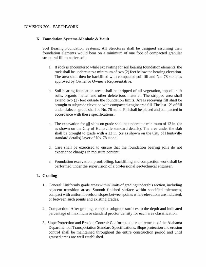
DIVISION 200 - EARTHWORK
K. Foundation Systems-Manhole & Vault
Soil Bearing Foundation Systems: All Structures shall be designed assuming their foundation elements would bear on a minimum of one foot of compacted granular structural fill to native soil.
a. If rock is encountered while excavating for soil bearing foundation elements, the
rock shall be undercut to a minimum of two (2) feet below the bearing elevation. The area shall then be backfilled with compacted soil fill and No. 78 stone as approved by Owner or Owner’s Representative.
b. Soil bearing foundation areas shall be stripped of all vegetation, topsoil, soft
soils, organic matter and other deleterious material. The stripped area shall extend two (2) feet outside the foundation limits. Areas receiving fill shall be brought to subgrade elevation with compacted-engineered fill. The last 12" of fill under slabs on grade shall be No. 78 stone. Fill shall be placed and compacted in accordance with these specifications.
c. The excavation for all slabs on grade shall be undercut a minimum of 12 in. (or
as shown on the City of Huntsville standard details). The area under the slab shall be brought to grade with a 12 in. (or as shown on the City of Huntsville standard details) layer of No. 78 stone.
d. Care shall be exercised to ensure that the foundation bearing soils do not
experience changes in moisture content.
e. Foundation excavation, proofrolling, backfilling and compaction work shall be performed under the supervision of a professional geotechnical engineer.
L. Grading
1. General: Uniformly grade areas within limits of grading under this section, including
adjacent transition areas. Smooth finished surface within specified tolerances, compact with uniform levels or slopes between points where elevations are indicated, or between such points and existing grades.
2. Compaction: After grading, compact subgrade surfaces to the depth and indicated
percentage of maximum or standard proctor density for each area classification. 3. Slope Protection and Erosion Control: Conform to the requirements of the Alabama
Department of Transportation Standard Specifications. Slope protection and erosion control shall be maintained throughout the entire construction period and until grassed areas are well established.

DIVISION 200 - EARTHWORK
M. Field Quality Control
1. Quality Control Testing During Construction: Allow the Geotechnical Engineer to inspect and report to the Owner or Owner’s Representative on findings and approve sub-grades and fill layers before further construction work is performed. Perform field density tests in accordance with ASTM D 1556 (sand cone method), ASTM D 2167 (rubber balloon method), or ASTM D 2992 (nuclear density method), as applicable and at a frequency necessary to be reasonably assured that adequate compaction is achieved.
2. If in the opinion of the Owner or Owner’s Representative, based on testing service
reports and inspection, subgrade or fills, which have been placed are below specified density, the Contractor shall provide additional compaction and testing at no additional expense to the Owner.
N. Maintenance
1. Reconditioning Compacted Areas: Where completed compacted areas are disturbed
by subsequent construction operations or adverse weather, scarify surface, reshape, and compact to required density prior to further construction.
2. Settling: Where settling is measurable or observable at excavated areas during
general project warranty period, remove surface (pavement, or other finish), add backfill material, compact, and replace surface treatment. Restore appearance, quality, and condition of surface or finish to match adjacent work, and eliminate evidence of restoration to greatest extent possible.
O. Disposal Of Excess Non-Organic Soil And Rock
All excess excavated material shall become the property of the Contractor and shall be disposed by him outside the project limits. It is the Contractor's responsibility to locate a suitable legal waste area off-site, obtain necessary permits or use of the waste area and be in compliance with applicable laws and regulations.
- END OF SECTION -

DIVISION 200 - EARTHWORK
SECTION 203 ROCK REMOVAL
203.01 DESCRIPTION OF WORK
The work under this section shall cover the following topics:
1. Removal of discovered rock during excavation. 2. Use of explosives for rock removal.
All work included in this section shall follow the standards of the Federal Occupational Safety and Health Act and the Alabama Department of Labor. The “Owner” shall refer to the City of Huntsville’s Engineering Department and/or Water Pollution Control. The Owner’s Representative” shall refer to the Design Engineer.
203.02 MATERIALS
A. Definitions
1. Rock Definition: Solid mineral material that cannot be removed with a power shovel. 2. Explosives: Type recommended by explosives firm and required by authorities
having jurisdiction. 3. Delay Devices: Type recommended by explosives firm and conforming to State
regulations. 4. Blasting Materials: Type recommended by explosives firm and conforming to State
regulations.
203.03 CONSTRUCTION REQUIREMENTS
A. References
1. NFPA 495 - Code for the Manufacture, Transportation, Storage and Use of Explosive Materials.
2. City of Huntsville Code of Ordinances, Chapter 12, Article III, State of Alabama,
and Federal Laws and Regulations Governing Explosives and Blasting.

DIVISION 200 - EARTHWORK
B. Quality Assurance
1. Seismic Survey Firm: Company specializing in seismic surveys with five years documented experience.
2. Explosives Firm: Company specializing in explosives for disintegration of
subsurface rock with five years documented experience.
C. Regulatory Requirements
1. Conform to State of Alabama code for explosive disintegration of rock. 2. Obtain permits from local authorities having jurisdiction before explosives are
brought to site or drilling is started. 3. Contractor shall conform to all State, Federal, and City laws, ordinances and
regulations in regard to transportation, use, and handling of explosives. 4. Indicate proposed method of blasting, delay pattern, explosive types, type of blasting
mat or cover, and intended rock recovery method. 5. Blasting shall be coordinated through the Fire Department. The Contractor shall
adhere to all local ordinances.
D. Inspection
1. The Contractor shall verify site conditions and note irregularities affecting work of this Section.
2. A pre-blast survey must be performed on all structures within a 1500-foot radius of
all blast sites, in accordance with the Alabama Department of Transportation's standard specifications, and applicable City of Huntsville standards.
3. Beginning work of this Section means acceptance of existing condition.
E. Rock Removal - Mechanical Methods
1. Cut away rock at excavation bottom to form even surface. 2. In utility trenches, excavate to 6 inches below invert elevation of pipe and 24 inches
wider than pipe diameter.

DIVISION 200 - EARTHWORK
F. Rock Removal - Explosives Methods
1. If rock is uncovered requiring the explosives method for rock disintegration, notify the Owner or Owner’s Representative.
2. Advise owners of adjacent buildings or structures as well as utility companies in
writing prior to setting up seismographs. Describe blasting and seismic operations.
3. Peak particle velocity will be limited to 4.0 in/sec. 4. Provide seismographic monitoring during progress of all blasting operations, or as
required by State regulations. 5. Disintegrate rock and remove from excavation. 6. Contractor shall conduct all blasting in accordance with the “City of Huntsville Code
of Ordinances, Chapter 12: Environmental Management, Article III. Blasting” G. Field Quality Control
1. Owner or Owner’s Representative shall approve of final rock cut. 2. If rock is excavated beyond the limits of excavation indicated on the Plans, specified
or authorized in writing by the Owner or Owner’s Representative, the excess excavation, whether resulting from overbreakage or other causes, shall be backfilled by and at the expense of the Contractor, as specified below in this section.
3. In pipe trenches, excess excavation below the elevation of the top of the bedding,
cradle, or envelope shall be filled with material of the same type, placed and compacted in the same manner as specified for the bedding, cradle, or envelope. Excess excavation above said elevation shall be filled with earth as specified in Section 202, "Excavating, Backfilling and Compacting for Sanitary Sewers".
H. Blasting Precautions
1. All operations involving explosives shall be conducted with all possible care to avoid injury to persons and property. Blasting shall be done only with such quantities and strengths of explosives and in such manner as will break the rock approximately to the intended lines and grades and yet will leave the rock not to be excavated in an unshattered condition.

DIVISION 200 - EARTHWORK
2. Care shall be taken to avoid excessive cracking of the rock upon or against which any structure will be built and to prevent injury to existing pipes or other structures and property above or below ground.
3. Rock shall be well covered with logs or mats or both where required. 7. Sufficient warning shall be given to all persons in the vicinity of the work before a
charge is exploded. 8. All blasting shall be completed within a distance of 50 feet before any portion of a
structure is placed or any pipe is laid.
I. Blasting Records
The Contractor shall keep and submit to the Owner or Owner’s Representative an accurate record of each blast. The record shall show the general location of the blast, the depth and number of drill holes, the kind and quantity of explosive used, kind and number and interval of delay periods used, and other data required for a complete record.
J. Shattering Rock
1. Shattering rock at ends of pipe and elsewhere as indicated on the Plans shall be done by drilling and blasting a single line of holes in the vertical face of the rock at the end of the trench.
2. Drillholes shall have a minimum depth of 4 feet and maximum spacing of 18 in. on
centers. Sufficient explosive shall be used to shatter the rock for future excavation. Shattering shall be completed before any pipe or fitting is placed within 50 feet of rock to be shattered.
3. If the rock below normal depth is shattered due to drilling or blasting operations of
the Contractor, and the Owner or Owner’s Representative considers such shattered rock to be unfit for foundations, the shattered rock shall be removed and the excavation shall be backfilled with gravel. All such removal and backfilling shall be done by and at the expense of the Contractor.
K. Preparation of Rock Surfaces
1. Whenever so directed during the progress of the work, the Contractor shall remove all dirt and loose rock from designated areas and shall clean the surface of the rock thoroughly, using steam to melt snow and ice if necessary. Water in depressions shall then be removed as required so that the whole surface of the designated area can be inspected to determine whether seams or other defects exist.
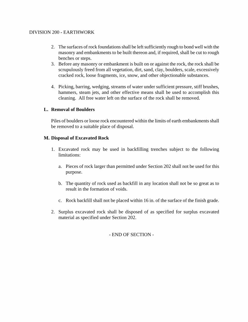
DIVISION 200 - EARTHWORK
2. The surfaces of rock foundations shall be left sufficiently rough to bond well with the masonry and embankments to be built thereon and, if required, shall be cut to rough benches or steps.
3. Before any masonry or embankment is built on or against the rock, the rock shall be scrupulously freed from all vegetation, dirt, sand, clay, boulders, scale, excessively cracked rock, loose fragments, ice, snow, and other objectionable substances.
4. Picking, barring, wedging, streams of water under sufficient pressure, stiff brushes,
hammers, steam jets, and other effective means shall be used to accomplish this cleaning. All free water left on the surface of the rock shall be removed.
L. Removal of Boulders
Piles of boulders or loose rock encountered within the limits of earth embankments shall be removed to a suitable place of disposal.
M. Disposal of Excavated Rock
1. Excavated rock may be used in backfilling trenches subject to the following limitations:
a. Pieces of rock larger than permitted under Section 202 shall not be used for this
purpose. b. The quantity of rock used as backfill in any location shall not be so great as to
result in the formation of voids. c. Rock backfill shall not be placed within 16 in. of the surface of the finish grade.
2. Surplus excavated rock shall be disposed of as specified for surplus excavated material as specified under Section 202.
- END OF SECTION -

DIVISION 200 – EARTHWORK
SECTION 204 SUBSURFACE INVESTIGATION
204.01 DESCRIPTION OF WORK
This section shall cover the minimum requirements for Subsurface Investigation. All projects shall require subsurface investigations unless otherwise directed by the Owner. The investigations may include the following types of studies or inspections: rock soundings, various soil tests when deemed necessary, groundwater levels, etc. A licensed Geotechnical Engineer shall perform all studies and investigations covered under this section. Work shall be performed during the design phase. All work included in this section shall follow the standards of the Federal Occupational Safety and Health Act and the Alabama Department of Labor. The “Owner” shall refer to the City of Huntsville’s Engineering Department and/or Water Pollution Control. The Owner’s Representative” shall refer to the Design Engineer.
204.02 MATERIALS
All materials, methods and equipment used during the subsurface investigations shall be standard documented procedures by regulating agencies such as ASTM Standards.
204.03 CONSTRUCTION REQUIREMENTS
Rock soundings shall be at intervals of no greater than 500 feet along the proposed sewer line and to at least one foot below the depth of the sewer at the location of the sounding. The soundings shall be conducted at closer intervals, if rock is encountered, as determined by the Owner or Owner’s Representative. Geotechnical Reports shall be included with bid documents when applicable. The Geotechnical Reports shall be intended for informational purposes only. The inclusion of these Reports does not relieve the Contractor of the responsibility to investigate and make determinations as to soil types, stability, groundwater level, bearing pressures, etc. in the work areas.
- END OF SECTION -

DIVISION 600 - INCIDENTALS
SECTION 644 DEWATERING
644.01 DESCRIPTION OF WORK
This section shall cover the work of furnishing all labor and equipment required to dewater all excavations. Dewatering of all excavations shall be the responsibility of the Contractor. The presence of groundwater and surface water can be anticipated during construction. All work included in this section shall follow the standards of the Federal Occupational Safety and Health Act and the Alabama Department of Labor. The “Owner” shall refer to the City of Huntsville’s Engineering Department and/or Water Pollution Control. The Owner’s Representative” shall refer to the Design Engineer.
644.02 MATERIALS
None specified. 644.03 CONSTRUCTION REQUIREMENTS
A. Dewatering of many of the construction excavations may be required to provide a dry work environment. Dewatering equipment shall be of adequate size and quantity to assure maintaining proper conditions for installing pipe, concrete, backfill or other material or structure in the excavation. Dewatering shall include proper removal of any and all liquid, regardless of its source, from the excavation and the use of all practical means available to prevent surface runoff from entering any excavation.
B. Extra pumps shall be maintained on site for use in the event of a breakdown of operating
pumps.
C. Drainage: 1. To ensure proper conditions at all times during construction, the Contractor shall
provide and maintain ample means and devices (including spare units kept ready for immediate use in case of breakdowns) with which to intercept and/or remove promptly and dispose properly of all water entering trenches and other excavations. Such excavation shall be kept dry until the structures, pipes, and appurtenances to be built therein have been completed to such extent that they will not be floated or otherwise damaged.
2. All water pumped or drained from the work shall be disposed of in a suitable
manner without undue interference with other work, damage to pavements, other surfaces, or property. Suitable temporary pipes, flumes, or channels shall be provided for water that may flow along or across the site of the work. All

DIVISION 600 - INCIDENTALS
groundwater/leachate pumped from site shall be drained to nearby sanitary sewer upon approval from the Owner.
a. Temporary Underdrains: Temporary underdrains, if used, shall be laid in
trenches beneath the grade of the structure. Trenches shall be of suitable dimensions to provide room for the chosen size of underdrain and its surrounding gravel.
Underdrain pipe shall be acceptable vitrified-clay or concrete pipe of
standard thickness. Sewer pipe of the quality known as "seconds" will be acceptable.
Underdrains, if used, shall be laid at a suitable distance below the bottom
of the normal excavation and with open joints wrapped in cheese cloth, and entirely surrounded by graded gravel, or crushed stone to prevent the admission of sand or other soil into the underdrains. The distance between the bottom of the pipe or structure and the top of the bell of the underdrain pipe shall be at least 3 in unless otherwise permitted. The space between the underdrain and the pipe or structure shall be filled with screened gravel or crushed stone which shall be rammed if necessary and left with a surface suitable for laying the pipe or building the structure.
b. Drainage Wellpoint System: If necessary, the Contractor shall dewater
the excavations by means of an efficient drainage wellpoint system which will drain the soil and prevent saturated soil from flowing into the excavation. The wellpoints shall be designed especially for this type of service. The pumping unit shall be designed for use with the wellpoints, and shall be capable of maintaining a high vacuum and of handling large volumes of air and water at the same time.
The installation of the wellpoints and pump shall be done under the
supervision of a competent representative of the manufacturer. The Contractor shall do all special work such as surrounding the wellpoints with sand or gravel or other work, which is necessary for the wellpoint system to operate for the successful dewatering of the excavations.
- END OF SECTION -

DIVISION 600 - INCIDENTALS
SECTION 645 SANITARY SEWERS
645.01 DESCRIPTION OF WORK
This section shall cover all labor, materials, equipment and services required for furnishing and installing all new sanitary sewers, the connection of new sanitary sewers to existing sanitary sewers and the testing of all sanitary sewer lines. This work shall also include the furnishing and construction of joints, cutting, and connection to other pipes as may be required by the plans or directed to provide an acceptable facility. The piping specified in this section includes sanitary sewer gravity lines and forcemains. Sanitary sewer manholes are specified in Section 646. All sanitary sewer gravity lines shall be designed in accordance with the City of Huntsville, Engineering Department, “Design and Acceptance Manual for Sanitary Sewers”. All work included in this section shall follow the standards of the Federal Occupational Safety and Health Act and the Alabama Department of Labor. The “Owner” shall refer to the City of Huntsville’s Engineering Department and/or Water Pollution Control. The Owner’s Representative” shall refer to the Design Engineer.
645.02 MATERIALS
A. Ductile Iron Pipe (DIP)
1. General a. All ductile iron pipe shall conform to ANSI/AWWA C150/A21.50 and
ANSI/AWWA C151/A21.51, latest revision. Ductile iron pipe for buried service shall be class and size as specified on Drawings. Minimum requirements for pressure class of buried service ductile iron pipe are listed in the table below.
Pipe Diameters Minimum Pressure Class Up to and including 12” 350 14” up to and including 24” 250 Greater than 24” 150
Pipe fabricated for above ground service, with flanged joints, shall be fabricated in accordance with ANSI/AWWA C115/A21.15 and shall be Pressure Class 350 for up to and including 12” and Pressure Class 250 for pipe greater than 12”.
b. The lining and coating for DIP shall meet the following requirements: Unless
otherwise specified, the interior of the pipe and fittings shall be cement mortar lined with bituminous seal coat in accordance with ANSI/AWWA C104/A21.4.

DIVISION 600 - INCIDENTALS
Thicknesses of the lining shall be as recommended by pipe manufacturer, unless otherwise directed by the Owner or Owner’s Representative. Protecto 401 Ceramic Epoxy liner or approved equal shall be used when called for on the Drawings or as directed by the Owner or Owner’s Representative. All approved linings shall meet the testing requirements of ASTM E-96-66, ASTM B-117, ASTM G-95 and ASTM D-714-87. Minimum thickness of the lining shall be 40 mils. All touch up and repair jobs shall be completed in accordance with manufacturer’s recommendations.
c. The exterior of all pipe and fittings, unless otherwise specified, shall receive
either coal tar or asphalt base coating with a minimum of 1 mil thick. d. All ductile iron installed shall be encased with polyethylene tube in accordance
with ANSI/AWWA-C105/A21.5 when soil tests deem necessary, when other circumstances warrant, or as specified by Owner or Owner’s Representative. The film shall be manufactured of virgin polyethylene material per ANSI D4976. Eight (8) mil thick polyethylene shall be furnished in minimum 20-in. flat width or as appropriate for the pipe diameter to be encased. Tensile strength and elongation properties shall be as specified in ASTM D882.
e. Each piece of pipe shall bear the manufacturer's name or trademark, the year in
which it was produced and the letters "DI" or word "DUCTILE". Pipe manufacturer shall furnish notarized certificate of compliance to the above AWWA or ANSI specifications.
f. The cleaning and assembly of pipe and fitting joints shall be in accordance with
the manufacturer's recommendations. g. All ductile iron pipe forcemain and service laterals shall have a metallic tape laid
2 foot below finished grade. The tape shall be green in color to identify the pipe use and have the words "CAUTION SANITARY SEWER" printed on it. Product shall be Seton Name Plate Corp., New Haven, CT, No. 210, or equivalent.
h. All ductile iron pipe and fittings shall be new, unused pipe delivered directly
from the manufacturer to the job site. Pipe, which has been stored by the Contractor for 3 months or longer, is not acceptable. All pipe must be approved by Owner or Owner’s Representative prior to installation.

DIVISION 600 - INCIDENTALS
2. Pipe Joint and Fittings
a. General
1. All items used for jointing pipe shall be furnished with the pipe and tested before shipment. The joints shall be made with tools and lubricant in strict conformity with the manufacturer's instructions. If requested, three (3) copies of such instructions shall be delivered to the Owner or Owner’s Representative at start of construction.
2. Push-in socket joints shall be equal to manufacturer's specifications for
"Tyton," "Bell-Tite," or "Fastite." The joints shall consist of a rubber ring gasket compressed in groove in bell of pipe with beveled spigot end of pipe for initial centering into rubber gasket in bell and conform to ANSI/AWWA C111/A21.11.
3. All ductile iron fittings shall be pressure rated 350 and shall be ductile cast
iron grade per ASTM A536 with same interior and exterior coatings as the pipe.
4. Mechanical joints shall be used where specifically called for on the Plans.
Mechanical joints are to be furnished according to ANSI/AWWA C111/A21.11. All pipe joints must be furnished complete with all accessories. Ductile iron mechanical joints shall be used for ductile iron pipe. Rubber gaskets shall be made of plain first grade rubber, free of imperfections and porosity. Hardness shall be 70 to 75 durometer.
b. Flanged Pipe and Fittings
1. Ductile iron flanges for pipe and fittings are to have dimensions, facing, and
drilling to correspond with ANSI B16.1 125 pound template with pressure rating 250.
2. Where flanges are pit cast integrally with pipe in vertical position in dry sand
molds, flanged pipe shall be latest revision of ANSI Specifications A21.2 for Class 150 or Class 250 pipe. Where flanged pipe is made up by threading plain end, centrifugally cast pipe, screwing on specially designed long hub flanges, and refacing across both face of flange and end of pipe, flange shall be per ANSI Specification B16.1 and pipe shall be ANSI Specification A21.6 Class 125. Either method of manufacture of flanged pipe will be acceptable; except when plain ends fit into mechanical joint bells, then centrifugally cast pipe shall be used.

DIVISION 600 - INCIDENTALS
3. With prior approval of the Owner or Owner’s Representative, the Contractor may use mechanical grooved or shouldered pipe couplings, flanges, and fittings, as manufactured by Victaulic Company of America or equal, conforming to ANSI/AWWA C606-97 on ductile iron piping systems in lieu of flanged joints. Grooved product manufacturer is to be certified ISO-9001 single supplier. The Contractor shall install the grooved system by means of reference to the manufacturer's most recent published instruction and ensure that the complete installation is similar in function to a flanged piping system.
4. With prior approval of the Owner or Owner’s Representative, couplings and
flanges for use with grooved and shouldered joints shall be ductile iron or malleable iron conforming to ASTM A-536 or A-47. Fittings shall be ductile, ASTM A-536, or cast iron, ASTM A-48. Fittings conforming to center to end dimensions, wall thickness, and rigid grooving dimensions for end pipe preparation as specified in AWWA C-110, AWWA C-153, and AWWA C-606 shall be required. Gaskets shall be the center leg design to conform to ductile pipe surfaces, have properties designated in ASTM A-2000, and shall be suitable for the required service. Bolts shall be heat treated, track head design, plated, and manufactured in accordance with ASTM A-183, minimum tensile 110,000 PSI or Type 304 stainless steel to ASTM A-193, Grade B-8, Class 2.
c. Restrained Joints, Reaction Anchorage and Blocking
1. Restrained joint pipe shall be furnished and installed in accordance with
these specifications and the manufacturer's recommendations, in the locations shown on the Plans. Restrained joints shall prevent "pulling apart" of push-on joints due to axial thrust forces. Joints shall restrain against working pressures at least equal to the working pressure rating of the pipe. Restrained joint fittings shall be equal to manufacturer's specifications for "TR FLEX", "Flex-Ring", "Lok-Ring", or other approved equal. Restrained joint fittings incorporating set-screws shall not be allowed.
2. In tunnel or boring applications only, restraining gaskets for push-on joints
may be used. Restraining gasket joints shall be equal to manufacturer's specifications for "Field Lok", "Fast-Grip", or other approved equal.
3. Reaction anchorage and blocking (thrust blocks) shall only be allowed where
specifically called for on the Plans, or at the direction of the Owner or Owner’s Representative.

DIVISION 600 - INCIDENTALS
a. Unplugged bell and spigot or bell tees, Y-branches, bends deflecting 11-1/4 degrees or more, and plugs which are installed in buried piping shall be provided with reaction blocking, anchors, joint harness, or other acceptable means for preventing movement of the pipe and joints caused by the internal test pressure.
b. Concrete blocking shall extend from the fittings to solid undisturbed
earth and shall be installed so that all joints are accessible for repair. The bearing area of concrete reaction blocking shall be as shown on the Plans or as directed by the Owner or Owner’s Representative. If adequate support against undisturbed ground cannot be obtained, metal harness anchorages consisting of steel rods across the joint, securely anchored to pipe and fitting or other adequate facilities, shall be installed to provide the necessary support.
c. Reaction blocking, anchorage, or other supports for fittings installed in
fills or other unstable ground or above grade shall be provided as shown on the Plans or as directed by the Owner or Owner’s Representative.
d. Flexible Couplings
1. Flexible couplings shall be installed where shown on the Plans. The type of
couplings used shall be approved by the Owner or Owner’s Representative. 2. Sleeve-type couplings for ductile iron pipe shall be of a gasketed, sleeve-type
with diameter to properly fit the outside diameter of the pipe. Each coupling shall consist of one (1) middle ring, two (2) follower rings, two (2) resilient gaskets and sufficient track-head steel bolts to properly compress the gaskets. The manufacturer shall supply information as to the recommended torque to which the bolts shall be tightened. Gaskets shall be of a compound which will not deteriorate from age, heat, or exposure to air under normal storage or operating conditions. The material shall be resilient and resist cold flow so that the joint will remain sealed and tight indefinitely when subjected to shock, vibration, pulsation, temperature or other adjustments of the pipeline. Couplings shall be as manufactured by Dresser Manufacturing Division, Bradford, PA; JCM Industries, Inc., Nash, TX; or approved equal.

DIVISION 600 - INCIDENTALS
3. Flanged coupling adapters for ductile iron pipe shall consist of a flanged-plain end sleeve with a follower ring, resilient gasket, and high-strength bolts for compression of the gasket. The manufacturer shall supply information as to the recommended torque to which the bolts shall be tightened. Gaskets shall be as specified for sleeve-type couplings. Flanged coupling adapters shall be as manufactured by Dresser Manufacturing Division, Bradford, PA; JCM Industries, Inc., Nash, TX; or approved equal.
4. Grooved-shoulder type couplings shall be cast of ductile iron conforming to
ASTM A-536 or malleable iron conforming to ASTM A-47 with an alkyd enamel coating, with a synthetic rubber gasket and plated nuts and bolts. Gaskets shall have elastomeric properties as designated in ASTM D-2000, and shall be suitable for service on raw sewage lines. All pipe to be joined using this type of coupling shall be cut grooved in accordance with ANSI/AWWA C-606, latest revision. Any lubricants used in the installation of flexible couplings shall be recommended by the coupling manufacturer. Grooved-shoulder type couplings shall be as manufactured by Victaulic of Easton, PA, or approved equal.
5. Where pipe connected with flexible couplings is subject to axial thrust forces
which may cause pipe pullout, pipe joints must be anchored (restrained). Anchorage shall be provided using tie rods or other method approved by the Owner or Owner’s Representative. Set screws shall not be considered an approved form of anchorage.
e. Cam and Groove Couplings
1. Where hoses must be connected to pipe to pump out tanks or pipe contents,
cam and groove type couplings shall be provided. 2. Ductile iron pipe to accept the coupling shall have male threads as required
by the coupling fitting. 3. The coupling fitting shall be female NPT, equivalent to American Packing
and Gasket Co. part no. 3TDSS (316 stainless steel) for use on the sizes of pipe shown on the Plans.
4. Each coupling shall be provided with a dust plug equivalent to American
Packing and Gasket Co. part no. 3TDPSS (316 stainless steel).
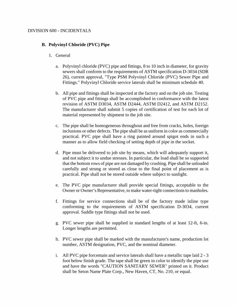
DIVISION 600 - INCIDENTALS
B. Polyvinyl Chloride (PVC) Pipe
1. General
a. Polyvinyl chloride (PVC) pipe and fittings, 8 to 10 inch in diameter, for gravity sewers shall conform to the requirements of ASTM specification D-3034 (SDR 26), current approval, "Type PSM Polyvinyl Chloride (PVC) Sewer Pipe and Fittings." Polyvinyl Chloride service laterals shall be minimum schedule 40.
b. All pipe and fittings shall be inspected at the factory and on the job site. Testing
of PVC pipe and fittings shall be accomplished in conformance with the latest revision of ASTM D3034, ASTM D2444, ASTM D2412, and ASTM D2152. The manufacturer shall submit 5 copies of certification of test for each lot of material represented by shipment to the job site.
c. The pipe shall be homogeneous throughout and free from cracks, holes, foreign
inclusions or other defects. The pipe shall be as uniform in color as commercially practical. PVC pipe shall have a ring painted around spigot ends in such a manner as to allow field checking of setting depth of pipe in the socket.
d. Pipe must be delivered to job site by means, which will adequately support it,
and not subject it to undue stresses. In particular, the load shall be so supported that the bottom rows of pipe are not damaged by crushing. Pipe shall be unloaded carefully and strung or stored as close to the final point of placement as is practical. Pipe shall not be stored outside where subject to sunlight.
e. The PVC pipe manufacturer shall provide special fittings, acceptable to the
Owner or Owner’s Representative, to make water-tight connections to manholes. f. Fittings for service connections shall be of the factory made inline type
conforming to the requirements of ASTM specification D-3034, current approval. Saddle type fittings shall not be used.
g. PVC sewer pipe shall be supplied in standard lengths of at least 12-ft, 6-in.
Longer lengths are permitted. h. PVC sewer pipe shall be marked with the manufacturer's name, production lot
number, ASTM designation, PVC, and the nominal diameter. i. All PVC pipe forcemain and service laterals shall have a metallic tape laid 2 - 3
foot below finish grade. The tape shall be green in color to identify the pipe use and have the words "CAUTION SANITARY SEWER" printed on it. Product shall be Seton Name Plate Corp., New Haven, CT, No. 210, or equal.

DIVISION 600 - INCIDENTALS
j. Five copies of directions for handling and installing shall be furnished to the Contractor from the manufacturer at the first delivery of the pipe to the job.
k. All PVC pipe and fittings shall be new, unused pipe delivered directly from the
manufacturer to the job site. Pipe, which has been stored by the Contractor for 3 months or longer, is not acceptable. All pipe must be approved by Owner or Owner’s Representative prior to installation.
2. Pipe Jointing for PVC Pipe
a. Polyvinyl Chloride (PVC) Pipe Joints: Jointing of PVC pipe shall be by a rubber
or organic compound ring inserted in the belled end of the pipe or double hub joints, or mechanical joint. Ring shall be corrosion resistant for specific service of piping. Solvent weld joints are not acceptable. All lubricants used in pipe jointing shall be per the manufacturer's recommendations.
b. Joints for PVC pipe shall be installed per the manufacturer's recommendations.
Pipe that has been field cut must be beveled for insertion into gasketed joints. Bevel can be made with hand or power tool. In either case, the finished bevel should be the same as the factory bevel. All pipe shall be provided with home marks to insure proper gasket seating. Gasket material shall comply with the physical requirements specified in ASTM D-1869, C-361, C-433, current approval.
C. Reinforced Concrete Pipe
1. General
a. Except as otherwise specified herein, pipe shall conform to ASTM Standard
Specifications for Reinforced Concrete Culvert, Storm Drain, and Sewer Pipe, Designation C 76, of the Class shown on the Plans. The supplier is responsible for the performance of all inspection requirements as specified in ASTM C 76. A complete set of records of the tests shall be submitted in accordance with these specifications.
b. Non-air-entraining portland cement conforming to ASTM Specification C 150,
Type II shall be used, except as otherwise approved in writing to the Owner or Owner’s Representative. The use of a non-bleeding, water-reducing, dispersing agent may be permitted subject to the specific approval of the Owner or Owner’s Representative. The use of any other admixture will not be permitted.
c. Aggregates shall conform to the requirements of ASTM Specification C 33,
latest edition, except for gradation.
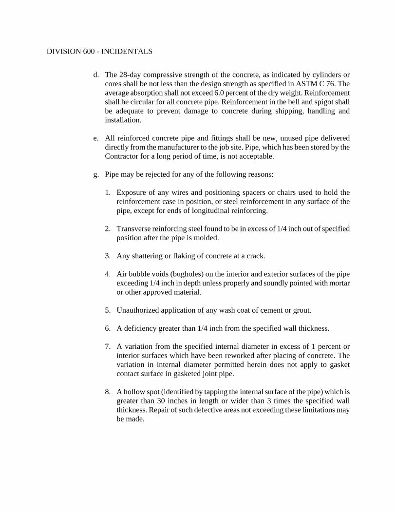
DIVISION 600 - INCIDENTALS
d. The 28-day compressive strength of the concrete, as indicated by cylinders or cores shall be not less than the design strength as specified in ASTM C 76. The average absorption shall not exceed 6.0 percent of the dry weight. Reinforcement shall be circular for all concrete pipe. Reinforcement in the bell and spigot shall be adequate to prevent damage to concrete during shipping, handling and installation.
e. All reinforced concrete pipe and fittings shall be new, unused pipe delivered
directly from the manufacturer to the job site. Pipe, which has been stored by the Contractor for a long period of time, is not acceptable.
g. Pipe may be rejected for any of the following reasons:
1. Exposure of any wires and positioning spacers or chairs used to hold the
reinforcement case in position, or steel reinforcement in any surface of the pipe, except for ends of longitudinal reinforcing.
2. Transverse reinforcing steel found to be in excess of 1/4 inch out of specified
position after the pipe is molded. 3. Any shattering or flaking of concrete at a crack. 4. Air bubble voids (bugholes) on the interior and exterior surfaces of the pipe
exceeding 1/4 inch in depth unless properly and soundly pointed with mortar or other approved material.
5. Unauthorized application of any wash coat of cement or grout. 6. A deficiency greater than 1/4 inch from the specified wall thickness. 7. A variation from the specified internal diameter in excess of 1 percent or
interior surfaces which have been reworked after placing of concrete. The variation in internal diameter permitted herein does not apply to gasket contact surface in gasketed joint pipe.
8. A hollow spot (identified by tapping the internal surface of the pipe) which is
greater than 30 inches in length or wider than 3 times the specified wall thickness. Repair of such defective areas not exceeding these limitations may be made.

DIVISION 600 - INCIDENTALS
9. Defects that indicate imperfect molding of concrete; or any surface defect indicating honeycomb or open texture (rock pockets) greater in size than area equal to a square with a side dimension of 2-1/2 times the wall thickness or deeper than two times the maximum graded aggregate size; or local deficiency of cement resulting in loosely bonded concrete, the area of which exceeds in size the limits of area described in paragraph 8 above when the defective concrete is removed. Repair of such defects not exceeding these limits may be made as provided in paragraph 8 above.
10. Any of the following cracks:
a. A crack having a width of 0.005 inch to 0.01 inch throughout a
continuous length of 36 inches or more. b. A crack having a width of 0.01 inch to 0.03 inch or more throughout a
continuous length of 1 foot or more. c. A crack greater than 0.005 inch extending through the wall of the pipe
and having a length in excess of the wall thickness. d. Any crack showing two visible lines of separation for a continuous length
of 2 feet or more, or an interrupted length of 3 feet or more anywhere in evidence, both inside and outside.
f. Cracks anywhere greater than 0.03 inch in width.
11. The pipe shall be clearly marked as required by ASTM C76. The markings
may be at either end of the pipe for the convenience of the manufacturer, but for any one size shall always be at the same end of each pipe length. Pipe shall not be shipped until the compressive strength of the concrete has attained the design strength.
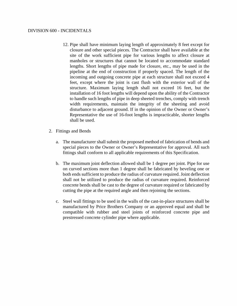
DIVISION 600 - INCIDENTALS
12. Pipe shall have minimum laying length of approximately 8 feet except for closure and other special pieces. The Contractor shall have available at the site of the work sufficient pipe for various lengths to affect closure at manholes or structures that cannot be located to accommodate standard lengths. Short lengths of pipe made for closure, etc., may be used in the pipeline at the end of construction if properly spaced. The length of the incoming and outgoing concrete pipe at each structure shall not exceed 4 feet, except where the joint is cast flush with the exterior wall of the structure. Maximum laying length shall not exceed 16 feet, but the installation of 16 foot lengths will depend upon the ability of the Contractor to handle such lengths of pipe in deep sheeted trenches, comply with trench width requirements, maintain the integrity of the sheeting and avoid disturbance to adjacent ground. If in the opinion of the Owner or Owner’s Representative the use of 16-foot lengths is impracticable, shorter lengths shall be used.
2. Fittings and Bends
a. The manufacturer shall submit the proposed method of fabrication of bends and special pieces to the Owner or Owner’s Representative for approval. All such fittings shall conform to all applicable requirements of this Specification.
b. The maximum joint deflection allowed shall be 1 degree per joint. Pipe for use
on curved sections more than 1 degree shall be fabricated by beveling one or both ends sufficient to produce the radius of curvature required. Joint deflection shall not be utilized to produce the radius of curvature required. Reinforced concrete bends shall be cast to the degree of curvature required or fabricated by cutting the pipe at the required angle and then rejoining the sections.
c. Steel wall fittings to be used in the walls of the cast-in-place structures shall be
manufactured by Price Brothers Company or an approved equal and shall be compatible with rubber and steel joints of reinforced concrete pipe and prestressed concrete cylinder pipe where applicable.

DIVISION 600 - INCIDENTALS
3. Joints for Concrete Pipe
a. Pipe joints shall be of the rubber gasket type in which the gaskets are in compression and which will permit both longitudinal and angular movement. Each unit of pipe shall be provided with proper ends made of concrete formed true to size and formed on machined rings to ensure accurate joint surface. Joints and gaskets shall be O-ring or ribbed gasket type and shall conform to the requirements of ASTM Standard Specifications for Joints for Circular Concrete Sewer and Culvert Pipe, Using Rubber Gaskets, Designation C443, or ASTM Standard Specifications for Reinforced Concrete Low-Head Pressure Pipe, Designation C361 and to the additional requirements specified.
b. Gaskets shall be of a composition and texture which is resistant to common
ingredients of sewage, industrial wastes, and groundwater, and which will endure permanently under the conditions likely to be imposed by this service. Gaskets shall be the product of a manufacturer having at least five years' experience in the manufacture of the rubber gaskets for the pipe joints.
c. The gaskets shall be designed and manufactured so that the completed joint will
withstand an internal hydrostatic pressure of 13 psi for a period of 10 minutes without showing any leakage by the gasket or displacement of it (see ASTM C 443). The pipe manufacturer shall provide facilities for testing the effectiveness of the joints against leakage and one such test may be required for 1 percent of pipe for each type of joint manufactured.
d. With prior approval of the Owner or Owner’s Representative, Victaulic
Company of America grooved or shouldered end system may be used, referenced to the manufacturer's recommendations.
4. Coating and Lining for Concrete Sewer Pipe
a. General: Where shown on the Plans or the Pipe Schedule, concrete pipe shall be lined at the manufacturer's plant with a high build, 2-component amine-cured epoxy system and the spigot ends coated to give full protection to the area exposed in the bell of the joint. Instructions for coating and lining the concrete pipe shall apply to the total interior of the pipe and the exterior of the spigot end.
b. The pipe manufacturer shall submit complete information on the proposed
system, method of application and name of applicator to the Owner or Owner’s Representative and shall have received the Owner or Owner’s Representative's review and comments before undertaking any pipe coating or lining.

DIVISION 600 - INCIDENTALS
c. Material: The compound shall conform to Corps of Engineers Paint Specification
C2200 with modifications as required for application to concrete sanitary sewer pipe, for application with a high speed centrifugal airless device in a multipassed operation to produce the total required film thickness.
d. Surface Preparation: All interior and exterior surface areas, including pipe
jointing areas, shall be prepared for coating so as to remove all laitance form oil and other loose, foreign or deleterious materials which would adversely affect the bond of the lining compound to the pipe surface. Specifically, surface preparation shall consist of sandblasting and cleaning the barrel of the pipe and the joint surface areas on which the coatings will be applied.
e. After blasting and cleaning, all barrel surfaces shall be inspected, and if such
inspection reveals open holes, such holes shall be sealed in strict accordance with the coating manufacturer's written instructions. In all cases, the coating manufacturer's surface preparation requirements shall prevail and, if any questions arise, written instructions shall be solicited from the coating manufacturer by the Contractor and strictly followed.
f. Atmospheric and Substrate Conditions: The pipe surface areas to be lined and
coated shall be blown off with air to remove all sand, dust and other loose materials immediately prior to application of the lining compound. The compound must be applied on completely frost-free pipe surface and shall not be applied when the ambient temperature is below 40 degrees Fahrenheit.
g. Equipment: All application equipment shall be as recommended by the supplier
of the compound. The preferred method of application for the pipe barrel is by means of a high speed centrifugal airless device equipped to apply the material at a controlled rate and speed with multipass application along the longitudinal axis of the pipe to build up the coating to the prescribed thickness without localized buildup, lumping or sagging. Where such equipment is not available or is not recommended by the coating manufacturer, consideration may be given to application by manual brush or spray using not less than 2 successive coats with varying patterns to avoid ridges and holidays. Spray equipment or brush shall be utilized to coat the joint surfaces. Exterior surfaces may be sprayed or coated by brush.
h. Application: The compound shall be applied to the barrel of the pipe utilizing the
equipment specified so as to obtain a continuous and relatively uniform and smooth integral lining and coating.

DIVISION 600 - INCIDENTALS
i. The total dry film thickness shall be a minimum of 40 mils. The manufacturer shall furnish complete instructions as to build per coat, thinning and minimum as well as maximum drying time between coats, and such instructions shall be strictly followed by the applicator.
j. The coating shall be applied to all interior surfaces of the pipe including the bell,
and shall extend around the end and on the outside of the spigot end. Dry film thickness on the mating surface of the joints may be reduced to 8 to 10 mils if required to maintain clearance.
k. Applicator: In order to avoid controversy in the event of unsatisfactory results,
the applicator must be furnished by or approved by the coating manufacturer. The applicator must have a proven experience record of at least 3 years in the application of such coatings to concrete pipe, and must be acceptable to the Owner or Owner’s Representative.
l. Supervision and Control: Where the application is not performed by the coating
manufacturer, the manufacturer shall provide technical assistance as required to insure proper procedures and results.
m. The applicator shall regularly and routinely check the material temperature,
moisture content of the pipe sections and wet film thickness of the coated pipe. He shall also make available for use a holiday detector equal to Tinker & Rasor Model M-1 and shall check each coated pipe section for holidays.
n. Inspection: The pipe shall be inspected and labeled by the independent testing
laboratory provided by the Owner. The independent testing laboratory provided by the Owner will make random selections of up to 1 percent of the coated pipe sections which will be visually inspected, checked for holidays and tested for dry film thickness. Any changes in procedure or any recoating necessary to correct defective coating systems shall be carried out promptly upon notification of such deficiencies.
o. Repair of Coating: Any coating areas damaged in shipping, handling or installing
shall be repaired in accordance with material furnished by and in accordance with instructions of the coating manufacturer.
D. Tunneling, Boring and Jacking for Pipe Installation
The Contractor shall submit to the Owner or Owner’s Representative, details of the procedure proposed for work, along with a description of the equipment available for use.
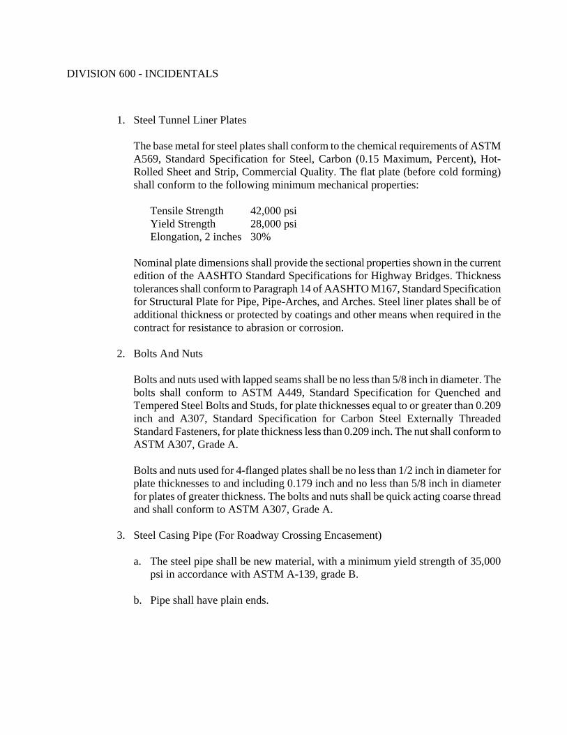
DIVISION 600 - INCIDENTALS
1. Steel Tunnel Liner Plates
The base metal for steel plates shall conform to the chemical requirements of ASTM A569, Standard Specification for Steel, Carbon (0.15 Maximum, Percent), Hot-Rolled Sheet and Strip, Commercial Quality. The flat plate (before cold forming) shall conform to the following minimum mechanical properties:
Tensile Strength 42,000 psi Yield Strength 28,000 psi Elongation, 2 inches 30%
Nominal plate dimensions shall provide the sectional properties shown in the current edition of the AASHTO Standard Specifications for Highway Bridges. Thickness tolerances shall conform to Paragraph 14 of AASHTO M167, Standard Specification for Structural Plate for Pipe, Pipe-Arches, and Arches. Steel liner plates shall be of additional thickness or protected by coatings and other means when required in the contract for resistance to abrasion or corrosion.
2. Bolts And Nuts
Bolts and nuts used with lapped seams shall be no less than 5/8 inch in diameter. The bolts shall conform to ASTM A449, Standard Specification for Quenched and Tempered Steel Bolts and Studs, for plate thicknesses equal to or greater than 0.209 inch and A307, Standard Specification for Carbon Steel Externally Threaded Standard Fasteners, for plate thickness less than 0.209 inch. The nut shall conform to ASTM A307, Grade A. Bolts and nuts used for 4-flanged plates shall be no less than 1/2 inch in diameter for plate thicknesses to and including 0.179 inch and no less than 5/8 inch in diameter for plates of greater thickness. The bolts and nuts shall be quick acting coarse thread and shall conform to ASTM A307, Grade A.
3. Steel Casing Pipe (For Roadway Crossing Encasement)
a. The steel pipe shall be new material, with a minimum yield strength of 35,000 psi in accordance with ASTM A-139, grade B.
b. Pipe shall have plain ends.

DIVISION 600 - INCIDENTALS
c. Steel shall comply with the appropriate requirements for the size shown in the following table and approved by the Owner or Owner’s Representative.
Pipe Diameter* Inches
Minimum Casing Diameter Inches
Minimum Wall Thickness Inches
8 18 0.250 12 24 0.250 20 30 0.312 42 54 0.500 48 60 0.625
*Minimum casing diameter shall be obtained by adding 10-inches to carrier pipe diameter and then rounding up to the next available steel pipe diameter. Consult steel casing manufacturer for the minimum wall thickness and obtain approval from Owner or Owner Representative.
4. Cement Grout for Filling Voids Outside of Tunnel Plates or Casing Pipe
Cement grout for filling voids outside tunnel liner plates and 24 inch and larger casing pipe, unless shown otherwise on the Plans, shall consist of a mixture of water and one part Type 1 Portland Cement to two parts mortar sand by volume. The water shall be adjusted to produce a mixture of consistency suitable for pumping, with a minimum slump of 5 inches and a maximum slump of 9 inches. Provisions shall be made for releasing of air and filling with grout. A pressure of 10 to 15 PSI shall be used.
5. Casing End Seals Casing End Seals as manufactured by the CASCADE System or approved equal shall be used to seal off each end of the casing pipe preventing backfill debris and seepage from entering the casing pipe. The seal shall be manufactured of virgin SBR. Stainless Steel bands shall be used to connect the end seal to the casing pipe and carrier pipe. The Owner or Owner’s Representative shall approve the installation.
645.03 CONSTRUCTION REQUIREMENTS
A. Pipe Laying
1. The pipe shall be protected during handling against impact shocks and free fall. Care shall be taken to avoid dragging the spigot ring on the ground or allowing it to be damaged by contact with gravel, crushed stone, or other hard objects.

DIVISION 600 - INCIDENTALS
2. After being delivered alongside the trench, the pipe shall be carefully examined for soundness or damage. All pipes shall be new and unused. No piece of pipe or fitting which is known to be defective shall be laid or placed in the lines. If any defective pipe or fitting shall be discovered after the pipe is laid, it shall be removed and replaced with a satisfactory pipe or fitting without additional charge. Before each piece of pipe is lowered into the trench, it shall be thoroughly cleaned out. Each piece of pipe shall be lowered separately unless special permission is given otherwise by the Owner or Owner’s Representative. In case a length of pipe is cut to fit in a line, it shall be so cut as to leave a smooth end at right angles to the longitudinal axis of the pipe.
3. The bell and spigot of the joint shall be cleaned of dirt and foreign matter
immediately prior to jointing. The contact surfaces shall be coated with a lubricant, primer or adhesive recommended by the pipe manufacturer, and pushed together until the joint snaps distinctly in place. The pushing together of the pipe may be done by hand or by the use of a bar.
4. All pipe shall be laid straight between changes in alignment and at uniform grade
between changes in grade. When jointed in the trench the pipe shall form a true and smooth line.
5. Trenches shall be kept dry during pipe laying. Before pipe laying is started, all water
that may have collected in the trench shall be removed.
6. All pipe shall be laid starting at the lowest point and installed so that the spigot ends point in the direction of the flow.
7. When pipe laying stops for any reason, the exposed end shall be closed with a
plywood plug fitted into the bell end, so as to protect it from intrusion of foreign material. The Contractor shall take all precautions to prevent intrusion of any foreign material into the pipe system. Precautions shall also be taken to prevent flotation of pipe caused by flooding of the trench from surface water or ground water.
B. Site Piping Installation
1. Excavation and backfilling for pipeline trenches shall be as specified in Section 202 - Excavating, Backfilling and Compacting for Sanitary Sewers, and as shown on the Plans.
2. Minimum cover for all pipelines shall be 3 ft. - 0 in., unless otherwise shown on the
Plans.
3. Jointing: The types of joints described hereinbefore shall be made in accordance with

DIVISION 600 - INCIDENTALS
the manufacturer's recommendations.
4. Bituminous Pavement Replacement: Sections of pavement shall be replaced as required to install the pipelines under the work of this Section. Pavement replacement shall be in accordance with the City of Huntsville standard details and the Alabama Department of Transportation Standard Specifications.
5. Before final acceptance, the Contractor will be required to level off all trenches or to
bring the trench up to grade. The Contractor shall also remove from roadways, rights-of-way and/or private property all excess earth or other materials resulting from construction in accordance with Section 202 – Excavating, Backfilling and Compacting for Sanitary Sewers.
C. Tunneling, Boring And Jacking Installation
1. General
a. Sewer pipe shall be constructed by tunneling or boring and jacking only at those locations and within limits shown on the Plans or as directed by the Owner or Owner’s Representative. Where pipe is required to be installed under railroads, highways, streets, or other facilities by tunneling or boring and jacking, construction shall be made according to the plans, specifications, and permit requirements in such a manner that will not interfere with the operation of the railroad street, highway, or other facility, and shall not weaken or damage any embankment or structure.
b. If any utility above or adjacent to the tunnel or bore is endangered or has been
damaged because of the tunneling or boring and jacking operations or movements of earth caused by such operations, the owner of same shall be notified immediately and shall be given access to the work to carry out all necessary repairs to such utilities.
c. The Contractor shall be responsible for protection of utilities, sewers, and drains
against damage by the work.
2. Dewatering

DIVISION 600 - INCIDENTALS
Prior to commencing, the Contractor shall furnish and operate all necessary pumping equipment of ample capacity and make all necessary provisions to keep tunnels, shafts and pits free of water during construction and to satisfactorily dispose of such water. During placing of concrete, drainage and pumping shall be so arranged that concrete is placed in the dry and that no water will flow over the concrete until it has hardened. For additional information on dewatering refer to Section 644.
3. Line and Grade
Line and grade shall be checked frequently by the Contractor's Professional Land Surveyor and not less than once per day. Results from these checks shall be provided to the Owner or Owner’s Representative. The Contractor also shall assist the Owner or Owner’s Representative in checking line and grade as often as the Owner or Owner’s Representative deems necessary to ensure that proper tolerances in line and grade are being met. Tunneled or bored and jacked sections of sewers shall be completely installed prior to construction of adjoining sections. If permitted by the Owner or Owner’s Representative, minor adjustments in the line and/or grade of the adjoining sections shall be allowed to compensate for slight deviations from the Drawing line and grade of the installed tunneled sections.
4. Tunneling
a. Submittals and Approvals
Tunnel support systems shall be with steel liner plates, ribs and lagging, steel casing pipe or other systems approved by the Owner or Owner’s Representative. The Contractor shall furnish a detailed Tunneling Plan for review by the Owner or Owner’s Representative. The plans shall contain a description of the tunneling method and equipment proposed, tunnel support system, shop drawings, details and cross-sections, a schedule of operations, and the proposed work hours. Tunnel construction shall not commence until the Owner or Owner’s Representative has reviewed the submittal and provided approval of plan. The Owner or Owner’s Representative's approval shall in no way relieve the Contractor of the sole responsibility for the execution of this work or any liability. When tunnel construction occurs under the Alabama Department of Transportation or Norfolk-Southern Railway Corporation right of ways or under a stream belonging in the Corps of Engineer's jurisdiction, the tunneling plan shall also be subject to the approval of the governing agency.
b. Safety

DIVISION 600 - INCIDENTALS
All work shall conform to 29 CFR, Part 1926, Subpart S, "Tunneling".
c. Working Hours
Work hours must be approved by the Owner as part of the construction schedule submittal. Tunnel construction operations may progress for 24 hours a day, except on Sundays. When work is done at night, the Contractor shall provide adequate safety precautions such as watchmen, barricades, lights, etc., and any mechanical equipment used in the construction operations shall be of a type that produces a minimum amount of noise to avoid creating a nuisance.
d. Tunnel Shafts
Shafts shall be constructed at the locations shown on the Plans. If not shown on the Plans, shafts shall be constructed at locations selected by the Contractor, subject to approval by the Owner or Owner’s Representative. Temporary construction shafts shall be of adequate size and properly constructed and equipped to meet all requirements of safety to personnel and to the work. All shafts shall be barricaded, lighted, fenced, and properly guarded from the beginning of the excavation until the completion of the construction requiring the shaft. A substantially constructed ladder shall be provided in each shaft and shall be kept in safe, good repair and clean and clear of debris. Provisions shall be made at each shaft so that plumb lines suspended on the centerline of the sewer at each end of the shaft will hang freely from the surface.
e. Tunnel Construction
The Contractor shall carry out the work of tunneling and supporting the tunnel face, roof, walls, and floor so that there will be no fall, flow, caving, or heaving of earth or other materials into the tunnel excavation. If there should be any fall or movement of earth into the tunnel at any time, the Contractor shall proceed with the work with all necessary precautions and in such a manner as will ensure the safety of life and of all sewers, utilities and public and private property above and adjacent to the tunnel. The Contractor shall furnish, place and maintain all sheeting, bracing or lining required to support the tunnel floor, roof, sides, and face until the pipe and its
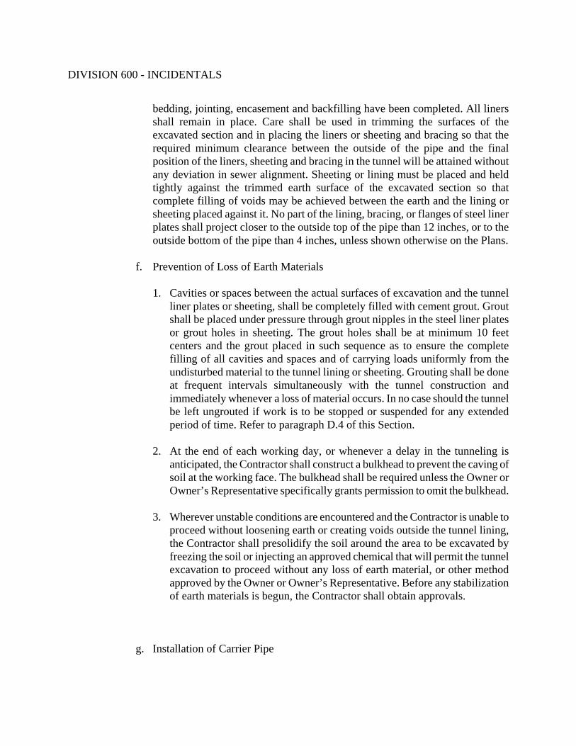
DIVISION 600 - INCIDENTALS
bedding, jointing, encasement and backfilling have been completed. All liners shall remain in place. Care shall be used in trimming the surfaces of the excavated section and in placing the liners or sheeting and bracing so that the required minimum clearance between the outside of the pipe and the final position of the liners, sheeting and bracing in the tunnel will be attained without any deviation in sewer alignment. Sheeting or lining must be placed and held tightly against the trimmed earth surface of the excavated section so that complete filling of voids may be achieved between the earth and the lining or sheeting placed against it. No part of the lining, bracing, or flanges of steel liner plates shall project closer to the outside top of the pipe than 12 inches, or to the outside bottom of the pipe than 4 inches, unless shown otherwise on the Plans.
f. Prevention of Loss of Earth Materials
1. Cavities or spaces between the actual surfaces of excavation and the tunnel liner plates or sheeting, shall be completely filled with cement grout. Grout shall be placed under pressure through grout nipples in the steel liner plates or grout holes in sheeting. The grout holes shall be at minimum 10 feet centers and the grout placed in such sequence as to ensure the complete filling of all cavities and spaces and of carrying loads uniformly from the undisturbed material to the tunnel lining or sheeting. Grouting shall be done at frequent intervals simultaneously with the tunnel construction and immediately whenever a loss of material occurs. In no case should the tunnel be left ungrouted if work is to be stopped or suspended for any extended period of time. Refer to paragraph D.4 of this Section.
2. At the end of each working day, or whenever a delay in the tunneling is
anticipated, the Contractor shall construct a bulkhead to prevent the caving of soil at the working face. The bulkhead shall be required unless the Owner or Owner’s Representative specifically grants permission to omit the bulkhead.
3. Wherever unstable conditions are encountered and the Contractor is unable to
proceed without loosening earth or creating voids outside the tunnel lining, the Contractor shall presolidify the soil around the area to be excavated by freezing the soil or injecting an approved chemical that will permit the tunnel excavation to proceed without any loss of earth material, or other method approved by the Owner or Owner’s Representative. Before any stabilization of earth materials is begun, the Contractor shall obtain approvals.
g. Installation of Carrier Pipe

DIVISION 600 - INCIDENTALS
1. All pipe used in tunnels shall be of the type shown on the Plans or in the Contract Documents and shall be of the size and strength class required.
2. After the tunnel section is excavated, lined, and braced, the carrier pipe shall
be placed on and supported by steel rails, a concrete pad, or other approved supports. The supporting system shall assure line and grade and shall allow sufficient space below the pipe for placing concrete. Care shall be used to avoid damage to the pipe or to the liner plates. The carrier pipe shall be rigidly braced to prevent its displacement during construction installation.
3. End seals as specified shall be used to seal off the space between the carrier pipe and sides of the roof of the tunnel. 4. Temporary shafts shall be completely abandoned. Unless otherwise specified
in the Plans or Contract Documents, all sheeting, bracing, and similar items may be removed unless the Contractor requests and receives authorization from the Owner or Owner’s Representative to leave it in place.
5. Boring and Jacking
a. Submittals and Approvals
Boring and jacking support systems shall be with steel casing pipe or other systems approved by the Owner or Owner’s Representative. The Contractor shall furnish a detailed Boring and Jacking Plan for review by the Owner or Owner’s Representative. The plans shall contain a description of the Boring and Jacking method and equipment proposed, boring and jacking support system, shop drawings, details and cross-sections, a schedule of operations, and the proposed work hours. Boring and Jacking construction shall not commence until the Owner or Owner’s Representative has reviewed and approved the submittal. The Owner or Owner’s Representative's approval shall in no way relieve the Contractor of the sole responsibility for the execution of this work or any liability. When boring and jacking occurs under the Alabama Department of Transportation or Norfolk-Southern Railway Corporation right of ways or under a stream belonging in the Corps of Engineers jurisdiction, the Boring and Jacking Plan shall also be subject to the approval of the governing agency.
b. Boring and Jacking Equipment and Construction
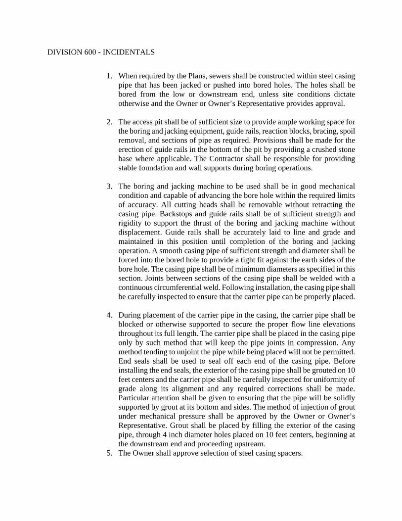
DIVISION 600 - INCIDENTALS
1. When required by the Plans, sewers shall be constructed within steel casing pipe that has been jacked or pushed into bored holes. The holes shall be bored from the low or downstream end, unless site conditions dictate otherwise and the Owner or Owner’s Representative provides approval.
2. The access pit shall be of sufficient size to provide ample working space for
the boring and jacking equipment, guide rails, reaction blocks, bracing, spoil removal, and sections of pipe as required. Provisions shall be made for the erection of guide rails in the bottom of the pit by providing a crushed stone base where applicable. The Contractor shall be responsible for providing stable foundation and wall supports during boring operations.
3. The boring and jacking machine to be used shall be in good mechanical
condition and capable of advancing the bore hole within the required limits of accuracy. All cutting heads shall be removable without retracting the casing pipe. Backstops and guide rails shall be of sufficient strength and rigidity to support the thrust of the boring and jacking machine without displacement. Guide rails shall be accurately laid to line and grade and maintained in this position until completion of the boring and jacking operation. A smooth casing pipe of sufficient strength and diameter shall be forced into the bored hole to provide a tight fit against the earth sides of the bore hole. The casing pipe shall be of minimum diameters as specified in this section. Joints between sections of the casing pipe shall be welded with a continuous circumferential weld. Following installation, the casing pipe shall be carefully inspected to ensure that the carrier pipe can be properly placed.
4. During placement of the carrier pipe in the casing, the carrier pipe shall be
blocked or otherwise supported to secure the proper flow line elevations throughout its full length. The carrier pipe shall be placed in the casing pipe only by such method that will keep the pipe joints in compression. Any method tending to unjoint the pipe while being placed will not be permitted. End seals shall be used to seal off each end of the casing pipe. Before installing the end seals, the exterior of the casing pipe shall be grouted on 10 feet centers and the carrier pipe shall be carefully inspected for uniformity of grade along its alignment and any required corrections shall be made. Particular attention shall be given to ensuring that the pipe will be solidly supported by grout at its bottom and sides. The method of injection of grout under mechanical pressure shall be approved by the Owner or Owner’s Representative. Grout shall be placed by filling the exterior of the casing pipe, through 4 inch diameter holes placed on 10 feet centers, beginning at the downstream end and proceeding upstream.
5. The Owner shall approve selection of steel casing spacers.

DIVISION 600 - INCIDENTALS
6. When unforeseen obstructions or conditions require abandonment of a partially completed bore hole, plug end of pipe by filling with grout. Then the Contractor shall backfill the abandoned bore hole and start a new hole.
6. Waterproofing
After installation of the carrier pipe within the encasement or tunnel pipe, the ends of the casing or tunnel shall be sealed with end seals as specified in this section.
D. Abandoned Lines
All sanitary sewer lines to be abandoned shall be as noted on the plans. All piping connected to abandoned manholes shall be plugged and filled with 24” of grout fill or flowable fill at each end as shown on the standard details. The manhole top shall be removed down to not less than 3 feet below final grade and the remaining portion shall be filled with crushed rock and capped with 12” of concrete or filled with flowable fill as shown on the standard details. All lines shall be abandoned per City of Huntsville standard details.
E. Stream Crossings
Ductile Iron Pipe shall be required at all creek and stream crossings. Ductile Iron Pipe shall extend from manhole to manhole. No pipe material changes will be allowed between manholes. Sewer lines shall cross the streams or creeks as near perpendicular to stream flow as possible. Contractor shall be responsible for acquiring all necessary permitting for working in or near a stream. All design specifications shall be approved by the appropriate agencies prior to construction. Three standard creek crossing details are included in the City of Huntsville standard details. Contractor shall be responsible for using Best Management Practices for erosion and sediment control as specified in these specifications and on the Drawings.
F. Clean-Up
Upon completion of the installation of the piping and appurtenances, the Contractor shall remove all debris and surplus construction materials resulting from the work. The Contractor shall grade the ground along each side of pipe trenches in a uniform and neat manner leaving the construction area in a shape as near as possible to the original ground line or to the grade shown on the Plans.
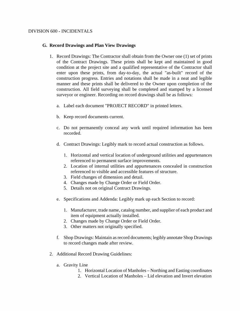
DIVISION 600 - INCIDENTALS
G. Record Drawings and Plan View Drawings 1. Record Drawings: The Contractor shall obtain from the Owner one (1) set of prints
of the Contract Drawings. These prints shall be kept and maintained in good condition at the project site and a qualified representative of the Contractor shall enter upon these prints, from day-to-day, the actual "as-built" record of the construction progress. Entries and notations shall be made in a neat and legible manner and these prints shall be delivered to the Owner upon completion of the construction. All field surveying shall be completed and stamped by a licensed surveyor or engineer. Recording on record drawings shall be as follows:
a. Label each document "PROJECT RECORD" in printed letters.
b. Keep record documents current.
c. Do not permanently conceal any work until required information has been
recorded.
d. Contract Drawings: Legibly mark to record actual construction as follows.
1. Horizontal and vertical location of underground utilities and appurtenances referenced to permanent surface improvements.
2. Location of internal utilities and appurtenances concealed in construction referenced to visible and accessible features of structure.
3. Field changes of dimension and detail. 4. Changes made by Change Order or Field Order. 5. Details not on original Contract Drawings.
e. Specifications and Addenda: Legibly mark up each Section to record:
1. Manufacturer, trade name, catalog number, and supplier of each product and
item of equipment actually installed. 2. Changes made by Change Order or Field Order. 3. Other matters not originally specified.
f. Shop Drawings: Maintain as record documents; legibly annotate Shop Drawings
to record changes made after review.
2. Additional Record Drawing Guidelines:
a. Gravity Line 1. Horizontal Location of Manholes – Northing and Easting coordinates 2. Vertical Location of Manholes – Lid elevation and Invert elevation

DIVISION 600 - INCIDENTALS
3. Changes in location of service lateral connection to main line. 4. Changes in length, slope, size, or material of lines.
b. Forcemains
1. Horizontal Location of Air Relief/Vacuum/Isolation Valves – Northing and Easting coordinates
2. Horizontal and Vertical Location of Fittings/Bends 3. Changes in length, size, depth or material of lines 4. Changes in restraint types
c. Pump Stations
1. Changes in Structural Requirements – (length, width, thickness, cover, laps, bar size, spacing, materials, etc.)
2. Changes in Site Development and/or Landscaping 3. Changes in Equipment
At completion of project, deliver record documents and plan view drawing to Owner. Record Drawings must be submitted and approved prior to acceptance of the sewers into the public system.
645.04 TESTING REQUIREMENTS AND INSPECTION
A. Testing of Pipes and Fittings (Gravity Lines)
1. General
It is recommended, but not required, that inspection and testing of the sewer lines and manholes be conducted prior to backfilling. Any documentation may be of benefit at the time of the final testing, which is mandatory after all other utilities are installed, roadway sub-grade is laid, and backfill is complete. Final testing requirements for sewer lines and manholes are listed in this Section and Section 646. The approval and acceptance of the sewer lines and manholes will be based on the final testing. The Contractor must provide a 72-hour notice prior to final testing. A representative from the Owner must be present during final testing procedures before it will be accepted as fulfilling the requirements of these specifications. A copy of all tapes and logs on testing results shall be submitted to the Owner. An independent testing firm as approved by the Owner shall conduct testing. Use of other testing firms shall require prior written approval from the Owner. Approved testing firms are available from the Owner.

DIVISION 600 - INCIDENTALS
2. Minimum Testing Requirements
a. After the sewer mains have been brought to completion, and prior to final inspection, the Contractor shall rod out the entire system by pushing through each individual line in the system, from manhole to manhole, appropriate tools for the removal from the lines of any and all dirt, debris and trash. If necessary during the process of rodding the system, water shall be turned into the system in such quantities to carry off the dirt, debris and trash. The dirt, debris and trash shall be collected and properly disposed of by the Contractor.
b. During the final inspection, the Contractor will inspect each individual line, from
manhole to manhole, either by use of lights, television or other means at his disposal to determine whether the completed lines are true to line and grade as laid out or as shown on the Plans.
c. Deflection Test (Mandrel Test)
1. The Owner or Owner’s Representative may require a deflection test to be
performed on all flexible pipe. The test shall be conducted after the final backfill has been in place at least 30 days to permit stabilization of the soil-pipe system.
2. No pipe shall exceed a deflection of 5 percent. If deflection exceeds 5
percent, replacement or correction shall be accomplished at the Contractor's expense.
3. The rigid ball or mandrell used for the deflection test shall be a diameter not
less than 95 percent of the average inside diameter of the pipe. The pipe shall be measured in compliance with ASTM D 2122 Standard Test Method of Determining Dimensions of Thermoplastic Pipe and Fittings. The test shall be performed without mechanical pulling devices. The Contractor shall thoroughly clean the line prior to the deflection test.
4. The Contractor shall pass through the system, under its own momentum, a
rigid ball or mandrell as specified above. All pipes that do not pass ball shall be replaced so that they do pass the ball.
d. All lines or sections of line that are found to be laid improperly with respect to
line or grade, found to contain broken or leaking sections of pipe, or are obstructed in such a manner that they cannot be satisfactorily corrected otherwise, shall be removed and replaced at the Contractor's expense.

DIVISION 600 - INCIDENTALS
e. The Contractor shall lay sewer mains so that the ground water infiltration shall not average more than 100 gallons per 24 hours per inch of nominal diameter per mile of pipe. The length of the main sewers shall be used in making the foregoing computation.
f. The Contractor shall provide continuous sanitary sewer service. The Contractor
shall be responsible for providing temporary wastewater collection and disposal until a satisfactory leakage test is obtained.
g. All apparatus and equipment required for testing shall be furnished by the
Contractor at no additional expense to the Owner.
3. Low Pressure Air Testing: a. General
The Contractor shall conduct Low Pressure Air Tests of all pipes before putting the new sewers into service. Tests shall be made from manhole to manhole at an average pressure of 3.0 psi greater than the average back pressure of any ground water present and shall be conducted in accordance with the test procedure outlined below. The maximum allowance for air loss during testing shall be determined from tables of minimum holding time for a pressure drop of 1.0 psi for the particular pipe size and length being tested. These tables are prepared by and may be obtained from the Uni-Bell Plastic Pipe Associated, and at least two copies shall be furnished the Owner or Owner’s Representative by the Contractor. A representative from the Owner must be present to witness each satisfactory air test before it will be accepted as fulfilling the requirements of these specifications.
b. Test Equipment
The Contractor shall be responsible for acquiring an approved independent testing firm with all necessary equipment and personnel required to conduct the tests. The equipment used shall be identical or equal to the Air-Loc system as manufactured by Cherne Industrial, Inc., Hopkins, Minnesota. Equipment used shall meet the following minimum requirements: 1. Pneumatic plugs shall have a sealing length equal to or greater than the
diameter of the pipe to be tested. 2. Pneumatic plugs shall resist internal test pressures without requiring bracing
or blocking.

DIVISION 600 - INCIDENTALS
3. All air used shall pass through a single control panel. 4. Three individual hoses shall be used for the following connections:
a. From control panel to pneumatic plugs for inflation. b. From control panel to sealed line for introducing the low pressure air. c. From sealed line to control panel for continually monitoring the air
pressure rise in the sealed line. c. Test Procedure
1. The sewer line to be tested shall be flushed and cleaned prior to the test (a wetted pipe surface will produce more consistent results).
2. All pneumatic plugs shall be seal-tested before being used in the actual test
installation. One length of pipe shall be laid on the ground and sealed at both ends with the pneumatic plugs to be checked. Air shall be introduced into the plugs to 25 psig. The sealed pipe shall be pressured to 5.0 psig. The plugs shall hold against this pressure without movement of the plugs out of the pipe.
3. Plug all pipe outlets with suitable test plugs. It is advisable to restrain
gasketed caps, plugs, or short pipe lengths with bracing stakes, clamps and tie-rods, or wire harnesses over the pipe bells.
4. If the sewer line to be tested is submerged in ground water, insert a pipe
probe (by boring or jetting) into the backfill material adjacent to the center of the pipe, determine the pressure in the probe when air passes slowly through it. This is the back pressure due to ground water submergence over the end of the probe. All gauge pressures in the test shall be increased by this amount.
5. Add air slowly to the portion of the sewer line installation under test until the
internal pressure is raised to 4.0 psig. 6. After an internal pressure of 4.0 psig is obtained, allow at least two (2)
minutes for the air temperature to stabilize, adding only the amount of air required to maintain pressure.

DIVISION 600 - INCIDENTALS
7. When the pressure decreases to 3.5 psig, start timing with a stopwatch. Determine the time, in seconds, that is required for the internal air pressure to reach 2.5 psig (a drop of 1.0 psig). Minimum permissible pressure holding times for runs of single pipe diameter and for systems of 4 inch laterals in combination with trunk lines are indicated in the following table in minutes.
Pipe Diameter (inches)
Minutes
4 2.5 6 4.0 8 5.0 10 6.5 12 7.5 15 9.5
8. When the sewer section to be tested contains more than one size of pipe, the
minimum allowable time shall be based on the largest diameter pipe in the section, and shall be the time shown in the table reduced by 0.5 minutes.
9. If the pressure drops 1.0 psig before the appropriate time shown on the table
has elapsed, the air loss rate shall be considered excessive and the section of pipe has failed the test.
10. If the section fails to meet these requirements, the Contractor shall determine
at his own expense, the sources of leakage, and he shall repair or replace all defective materials and/or workmanship to the satisfaction of the Owner or Owner’s Representative. The completed pipe installation shall then be re-tested and required to meet the requirements of this test.
11. It is recommended that inspection and testing of the sewer lines and
manholes be conducted prior to backfilling. All documentation should be retained and presented to Owner and Owner’s Representative at time of the final testing which is required after all other utilities are installed, roadway sub-grade is laid, and backfill is complete.
d. Safety Precautions

DIVISION 600 - INCIDENTALS
1. The air test may be dangerous if because of ignorance or carelessness a line
is improperly prepared. It is extremely important that the various plugs be installed and braced in such a way as to prevent blowouts. Since an internal pressure of 5 psi exerts a force of 250 pounds on an 8-inch plug, it should be realized that the sudden expulsion of a poorly installed plug or of a plug that is partially deflated before the pipe pressure is released can be very dangerous.
2. No one shall be allowed in the manholes of the section being tested at the
time of the test or until after the lines have been depressurized. 3. Pressurizing equipment shall include a regulator set at 10 psi to avoid over
pressurizing and damaging an otherwise acceptable line.
4. Smoke Testing Smoke testing may be required to locate leaks if the low air pressure testing fails. To test for leaks, the Owner or Owner’s Representative may also require that all completed sewers be tested by the so-called smoke method in which smoke is blown into closed-off sections of the sewers under pressure and observation made of any smoke appearing on top of the ground indicating the presence of such leaks. All such leaks or breaks discovered by the smoke tests shall be repaired and/or corrected by the Contractor at his own expense. Equipment and supplies required for smoke tests shall be furnished by the Contractor. The Contractor will be required to smoke test the first section (manhole to manhole) of each size of pipe and type of joint on each construction contract prior to backfilling to establish and check laying and jointing procedures. Other supplementary smoke tests prior to backfilling may be performed by the Contractor at his option; however, any such tests shall not supplant the final tests of the completed work unless such final tests are waived by the Owner or Owner’s Representative.
5. Exfiltration Test a. In order to test for infiltration sources, the Owner or Owner’s Representative may
also require exfiltration tests on each section of pipe between manholes after it has been laid but prior to backfilling of joints. Exfiltration testing may also be used if the low air pressure testing fails. Exfiltration tests shall be conducted by plugging the lower end of the section of sewer to be tested and filling the sewer with water to a point approximately five feet above the invert at the lower end and at least one foot above the pipe at the upper end, observing for leakage at all joints and measuring the amount of leakage for a given interval of time. Exfiltration shall not exceed 110 percent times the infiltration limits set out in

DIVISION 600 - INCIDENTALS
Paragraph A.2.e. ALL OBSERVED LEAKS SHALL BE CORRECTED EVEN THOUGH EXFILTRATION IS WITHIN THE ALLOWABLE LIMITS. Exfiltration tests will normally be required for flat sections of sewer that are expected to be below the wet-season ground water table.
b. The Contractor shall plug the open ends of all lines at the manhole so that
measurements may be made at each section of sewer line. This exfiltration test will not be made until the sewer line is completed, and the Contractor will be required to correct all conditions that are conducive to excessive infiltration and may be required to relay such sections of the line that may not be corrected otherwise. ALL OBSERVED LEAKS SHALL BE CORRECTED EVEN THOUGH INFILTRATION IS WITHIN ALLOWABLE LIMITS.
B. Inspection
After completion of laying and backfilling of new pipe, after all other utilities have been installed and after roadway sub-grade has been laid, the sewer installation shall be television inspected in accordance with Section 647. All service entrances shall be accounted for. No infiltration should be apparent. If the pipe is not acceptable to the Owner or Owner’s Representative, remedies shall be accomplished at the Contractor's expense and to the Owner's satisfaction.
- END OF SECTION -

DIVISION 600 - INCIDENTALS
SECTION 646 MANHOLES FOR SANITARY SEWERS
646.01 DESCRIPTION OF WORK
This Section shall cover the construction of manholes for sanitary sewers complete with the necessary cast iron frames, covers and steps in accordance with the plans and specifications at the locations and to the grades shown. All manholes shall be precast concrete units unless otherwise approved in writing by the Owner. All work included in this section shall follow the standards of the Federal Occupational Safety and Health Act and the Alabama Department of Labor. The “Owner” shall refer to the City of Huntsville’s Engineering Department and/or Water Pollution Control. The Owner’s Representative” shall refer to the Design Engineer.
646.02 MATERIALS
A. Pipe
All pipe and pipe fittings used for gravity sewers or forcemains on this project shall conform to the requirements of Section 645 – Sanitary Sewers.
B. Manholes
1. General
The Contractor shall construct all manholes for sanitary sewers as indicated on the City of Huntsville standard details and as specified herein.
2. Description
a. Manholes shall conform in shape, size, dimensions, materials, and other respects to the details indicated on the Plans or bound in the Specifications or as ordered by the Owner or Owner’s Representative.
b. All manholes shall have precast reinforced concrete developed bases. No
other type of base will be allowed. Sloping invert channels shall be constructed whenever the difference between the inlet and outlet elevation is two feet or less.

DIVISION 600 - INCIDENTALS
c. Manhole walls (barrels and cones) shall be precast concrete sections. The top of the eccentric cone shall be built of reinforced concrete adjustment rings to permit adjustment of the frame to meet the finished surface. No more than three adjustment rings (maximum of 12 inches) will be allowed.
d. The inverts of the developed bases shall conform accurately to the size of the
adjoining pipes. Side inverts shall be curved and main inverts (where direction changes) shall be laid out in smooth curves of the longest possible radius, which is tangent, within the manhole, to the centerlines of adjoining pipelines. Precast inverts meeting the above requirements will be allowed.
e. The cast-iron frames and covers shall be the standard frame and cover as
indicated on the City of Huntsville standard details and as specified hereinafter in this section.
f. All cast-in-place concrete shall be Class A and shall conform to the
requirements specified in the Alabama Department of Transportation, Standard Specifications.
g. All holes for pipe connections in barrels and bases shall have a flexible pipe-
to-manhole connector to prevent infiltration. The connector shall be Kor-N-Seal as manufactured by NPC Inc., or approved equivalent. The connectors shall be installed in the manhole wall in strict accordance with the recommendations of the connector manufacturer. All connectors shall comply with the requirements of ASTM C-923. The connectors shall be as shown on the City of Huntsville Standard Details.
h. Contractor shall provide precast manholes, which have been approved by the
Owner. i. All precast manholes shall be new, unused manholes delivered directly from the
manufacturer to the job site.
3. Definitions
The following definitions cover the types of manholes used.
a. Standard Manhole: A standard manhole is defined as any manhole that is greater than 5 feet in depth, as measured from the invert of the manhole base at its center to the finished ground.
b. Shallow Manhole: A shallow manhole is defined as any manhole that is 5
feet or less in depth, as measured in the preceding sentence.

DIVISION 600 - INCIDENTALS
c. Drop Manhole: A drop manhole is defined as any manhole having a
difference in elevation greater than 2 feet between inverts.
1. The drop shall be constructed as shown on the City of Huntsville standard details. The drop may be field constructed or be a factory pre-cast unit as approved by the Owner or the Owner’s Representative.
2. The drop connection piping shall be ductile iron pipe. The drop
connection piping shall be so encased in concrete that the tee and the ductile iron pipe laid upstream of the connection shall be totally contained within the concrete as shown on the City of Huntsville standard details
4. Precast Concrete Sections
a. Precast concrete sections and appurtenances shall conform to the ASTM Standard Specifications for Precast Reinforced Concrete Manhole Sections, Designation C-478, latest revision, with the following exceptions and additional requirements:
1. The wall sections shall not be less than 5 inches thick for a 48” diameter
manhole, 6 inches thick for a 60” diameter manhole and 7 inches thick for a 72” diameter manhole.
2. Type II or III cement shall be used except as otherwise permitted. 3. Sections shall be cured by subjecting them to thoroughly saturated steam at a
temperature between 100 degrees and 130 degrees F for a period of not less than 12 hours or, when necessary, for such additional time as may be needed to enable the sections to meet the strength requirements.
4. No more than two lift holes may be cast or drilled in each section. Lift hole
inserts shall be required. Lift eyes as provided by the manufacturer shall be inserted and used to move manhole sections. The lift systems shall be as manufactured by M.A. Industries or approved equivalent. Holes shall not penetrate the wall of the manhole. All lift holes, except those in the cone section, shall be plugged with non-shrink grout as specified in this section.
5. Flat slab tops shall not be used, unless otherwise directed by the Owner. 6. The date of manufacture and the name or trademark of the manufacturer shall
be clearly marked on the outside of the barrel.

DIVISION 600 - INCIDENTALS
7. Acceptance of the sections will be on the basis of material tests and
inspection of the completed product. 8. Eccentric cones shall be precast sections of similar construction. 9. Drop manholes shall be constructed in accordance with the City of Huntsville
standard details. Every effort shall be made to avoid using drop manholes when possible.
b. The tops of the bases shall be suitably shaped by means of accurate bell-ring
forms to receive the barrel sections.
5. Setting Precast Manhole Sections
a. Precast reinforced concrete manhole sections shall be set so as to be vertical and with sections in true alignment.
b. Joints between sections on a 48” diameter manhole shall be made watertight
through the use of a 1” diameter butyl sealant, CS-231, as manufactured by Conseal or approved equal, and a Hamilton Kent rubber gasket (pre-lubricated manhole rubber gasket) as supplied by Sherman Industries, or approved equal. This same method as described above shall be used for larger sized manholes. The manhole manufacturer shall provide appropriate sized sealants and gaskets for the larger diameter manholes. A detail of the method described above is shown on the City of Huntsville standard details. Gaskets shall conform to the ASTM Standard C-443, latest revision. A rubber gasket (ASTM C-443) and CS-231 shall be required at each joint.
C. Manhole Frames And Covers
1. General
a. The Contractor shall furnish all cast-iron manhole frames and covers conforming to the City of Huntsville standard details and as specified herein.
b. The castings shall be of good quality, strong, tough, even-grained cast-iron,
smooth, free from scale, lumps, blisters, sandholes, and defects of every nature which would render them unfit for the service for which they are intended. Contact surfaces of covers and frame seats shall be machined to prevent rocking of covers.
c. All castings shall be thoroughly cleaned and subject to a careful hammer inspection.

DIVISION 600 - INCIDENTALS
d. Castings shall be at least Class 30 conforming to the ASTM Standard
Specifications for Gray Iron Castings, Designation A-48, latest revision. Covers and Frames shall be made in the United States, and shall be made of materials from the United States.
e. All castings shall be provided unpainted. f. Unless otherwise specified, manhole frames and covers shall be self-sealing, and
shall be Vulcan Foundry Inc., V-1355, with two (2) non-penetrating pick holes, or equivalent.
g. Where indicated on the Plans, or where the top of manhole elevations are below
the 100-year flood elevation, manhole covers shall be of the watertight type. The frames and covers shall be self-sealing, and shall be Vulcan Foundry, Inc., V-2355 as shown on the City of Huntsville standard details, or equal. A watertight gasket seal shall be installed under the cover that prevents entry of water into the manhole. Watertight frame and covers shall be bolted to the manhole as shown on City of Huntsville Standard Details.
h. All covers shall be marked as shown on the City of Huntsville standard details.
Castings shall also be clearly marked with the manufacturers name, company logo, and “Made in USA” in cast letters.
i. Contractor shall provide manhole frame and covers, which have been approved
by the Owner.
2. Setting Manhole Frames and Covers
a. Manhole frames shall be set with the tops conforming to the required elevations set forth in paragraph 3 of this Article. A controlled expansion waterstop or butyl sealant of Conseal CS-231 or approved equal shall be placed beneath the frame and between each concrete adjusting ring. A maximum of three concrete adjustment rings (maximum of 12 inches) shall be used. Frame shall be set concentric with the top of the precast concrete masonry and in a full bed of non-shrink grout so that the space between the top of the manhole masonry and the bottom flange of the frame shall be completely filled and made watertight. A thick ring of non-shrink grout extending to the outer edge of the masonry shall be placed all around and on the top of the bottom flange. The non-shrink grout shall be smoothly finished and have a slight slope to shed water away from the frame.
b. Manhole covers shall be left in place in the frames on completion of the work at
the manholes.

DIVISION 600 - INCIDENTALS
2. Adjusting Manhole Frames and Covers to Grade
a. The top of the precast concrete eccentric cone of a standard manhole shall terminate 4 in. below existing grade in an unpaved non-traffic area other than in a residential yard and 13 in. below existing grade in a paved or unpaved traffic area and in a residential yard. The remainder of the manhole shall be adjusted to the required grade as described hereinafter in subparagraphs B of this article.
b. When a manhole is located in an unpaved non-traffic area other than a residential
yard, the frame and cover shall be adjusted to an elevation 3 in. to 5 in. above the existing grade at the center of the cover. If field changes have resulted in the installed manhole invert elevation to be lower than the invert elevation shown on the Plans, the adjustment to an elevation of 3 in. to 5 in. above existing grade shall be accomplished by the use of precast concrete adjustment rings. A maximum of three adjustment rings(maximum of 12 inches) shall be used. If field changes have resulted in the complete manhole invert to be greater than the invert shown on the Plans and the cover higher than 5 in. above existing grade, then the top of the barrel section, when used, shall be trimmed down so that the manhole cover, after installation, is no greater than 5 in. above existing grade at the center of the cover. The area around the adjusted frame and cover shall be filled with the required material, sloping it away from the cover at a grade of one (1) inch per foot. After installation the inside and outside surfaces of the concrete rings shall receive a waterproofing bitumastic coating.
c. When a manhole is located in a bituminous, concrete, or crushed stone traffic
area, or in a residential yard, the frame and cover shall be adjusted to the grade of the surrounding area by the use of precast concrete rings. A maximum of three adjustment rings (maximum of 12 inches) shall be used. The adjusted cover shall conform to the elevation and slope of the surrounding area. If field changes have resulted in the installed manhole invert elevation to be so much higher than the invert elevation shown on the Plans that the top of the eccentric cone, when used, is less than the thickness of the frame and cover (7 in.) from the grade of the surrounding area, then the top of the cone or barrel section shall be trimmed down enough to permit the cover, after installation, to conform to the elevation and slope of the surrounding area. After installation the inside and outside surfaces of the concrete rings shall receive a waterproofing bitumastic coating.
3. Precast Concrete Adjustment Rings

DIVISION 600 - INCIDENTALS
A maximum of three adjustment rings (maximum of 12 inches) shall be used per manhole as shown on the City of Huntsville Standard Details. Butyl sealant of Conseal CS-231 or approved equal shall be placed beneath the frame and between each concrete adjusting ring as shown on the City of Huntsville Standard Details.
D. Stubs In Manholes
1. Stubs shall be installed at all dead end manholes. 2. Stubs shall be set accurately to the required line and elevation and shall be installed
in the manhole masonry as indicated on the Plans. 3. Polyvinyl chloride (PVC) stubs shall be short pieces of PVC pipe with bell ends and
plugs. E. Manhole Steps
Manhole steps shall be of the polypropylene plastic type reinforced with ½” grade 60 steel reinforcement rod. The steps shall be of the size and configuration as shown in the City of Huntsville standard details. The steps shall be MA Industries PS1-PF on 16” centers in vertical alignment per ASTM C 478 or approved equal. The steps shall be embedded into the manhole wall a minimum of 3 inches and be centered under the manhole cover opening. The bottom step shall be a maximum of two (2) feet above the fillet. The steps shall be capable of withstanding a force of 350 pounds, applied at any place on the step and in any direction which projects from the point of application through a diameter of the step cross-section at that point, with no permanent deformation resulting.
F. Non-Shrink Grouts 1. General: All surfaces shall be cleaned and shall be free of debris, grease, oil, etc.
All loose concrete shall be removed prior to patching. All water used in mixing processes shall be clean and potable. All grouts shall be mixed and applied in strict accordance with manufacturer’s recommendations.
2. Manhole to Pipe Connection, Bench, and Invert: Grout shall be a non-shrink type,
rapid setting, corrosion resistant, cement based material. All grouting in these areas shall be preformed with Conspec All-Patch as manufactured by Conspec Marketing and Manufacturing Co., Inc., Kansas City, Kansas or with Strong Seal QSR as manufactured by The Strong Company, Pine Bluff, Arkansas or approved equivalent. Non-shrink grouts shall be mixed and applied in strict accordance with manufacturer’s recommendations.

DIVISION 600 - INCIDENTALS
3. Interior Joints, Lift Holes, and Connections: Grout shall be a non-shrink type, rapid
setting, corrosion resistant cement repair material. All grouting in these areas shall be preformed with Waterplug as manufactured by ChemRex, Inc., Shakopee, Minnesota or with BONSAL Instant Hydraulic Cement as manufactured by W.R. Bonsal Company, Charlotte, North Carolina or approved equivalent. Non-shrink grouts shall be mixed and applied in strict accordance with manufacturer’s recommendations.
4. Manhole Interior: Grout shall be a hydraulic cement coating that produces a
waterproof surface after application. Grout for manhole interior repairs shall be ThoRoc Brushbond as manufactured by Harris Specialty Chemicals, Inc., Jacksonville, Florida or approved equivalent. Non-shrink grouts shall be mixed and applied in strict accordance with manufacturer’s recommendations.
646.03 CONSTRUCTION REQUIREMENTS
A. Excavation For Manholes
Excavation for manholes shall be in accordance with Section 202 - Excavating, Backfilling, and Compacting for Sanitary Sewers.
B. Connection To Existing Manholes
When connecting sewers to existing manholes, the Contractor shall provide all diversion equipment and perform all work necessary to maintain sewage flow in existing sewers during connection to manholes. Refer to Section 648 – Maintaining Wastewater Flow for additional information. Where an existing manhole does not have existing stubs, it will be necessary for the Contractor to construct a new invert for the existing manhole. When connecting a new sewer line to an existing manhole, the existing manhole shall be core drilled and flexible boots shall be installed using stainless steel bands to connect the pipe. When connecting new manholes to existing sewers, the new manholes shall be equipped with flexible connectors as described in paragraph 646.02 of this Section. The new sewer line or manhole shall be connected to the existing sewer line as shown in the City of Huntsville standard details.
C. Testing Of Manholes
The Owner requires testing of all new public and private sanitary sewer lines and
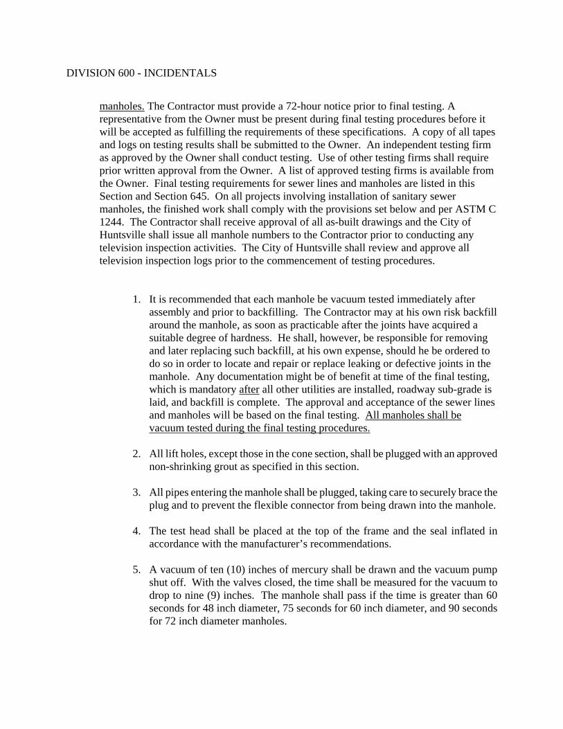
DIVISION 600 - INCIDENTALS
manholes. The Contractor must provide a 72-hour notice prior to final testing. A representative from the Owner must be present during final testing procedures before it will be accepted as fulfilling the requirements of these specifications. A copy of all tapes and logs on testing results shall be submitted to the Owner. An independent testing firm as approved by the Owner shall conduct testing. Use of other testing firms shall require prior written approval from the Owner. A list of approved testing firms is available from the Owner. Final testing requirements for sewer lines and manholes are listed in this Section and Section 645. On all projects involving installation of sanitary sewer manholes, the finished work shall comply with the provisions set below and per ASTM C 1244. The Contractor shall receive approval of all as-built drawings and the City of Huntsville shall issue all manhole numbers to the Contractor prior to conducting any television inspection activities. The City of Huntsville shall review and approve all television inspection logs prior to the commencement of testing procedures.
1. It is recommended that each manhole be vacuum tested immediately after assembly and prior to backfilling. The Contractor may at his own risk backfill around the manhole, as soon as practicable after the joints have acquired a suitable degree of hardness. He shall, however, be responsible for removing and later replacing such backfill, at his own expense, should he be ordered to do so in order to locate and repair or replace leaking or defective joints in the manhole. Any documentation might be of benefit at time of the final testing, which is mandatory after all other utilities are installed, roadway sub-grade is laid, and backfill is complete. The approval and acceptance of the sewer lines and manholes will be based on the final testing. All manholes shall be vacuum tested during the final testing procedures.
2. All lift holes, except those in the cone section, shall be plugged with an approved
non-shrinking grout as specified in this section. 3. All pipes entering the manhole shall be plugged, taking care to securely brace the
plug and to prevent the flexible connector from being drawn into the manhole. 4. The test head shall be placed at the top of the frame and the seal inflated in
accordance with the manufacturer’s recommendations.
5. A vacuum of ten (10) inches of mercury shall be drawn and the vacuum pump shut off. With the valves closed, the time shall be measured for the vacuum to drop to nine (9) inches. The manhole shall pass if the time is greater than 60 seconds for 48 inch diameter, 75 seconds for 60 inch diameter, and 90 seconds for 72 inch diameter manholes.

DIVISION 600 - INCIDENTALS
6. If the manhole fails the initial test, necessary repairs shall be made with a non-shrinking grout as specified in this Section. The contractor will be allowed to re-test the manhole one additional time. If the manhole fails the test a second time, the Contractor will be responsible for supplying and installing a brand new manhole. In addition, the Contractor will retest the new manhole as well as all pipe segments connected to the new manhole.
D. Abandoned Manholes
All manholes designated for abandonment shall be noted on the Plans. Existing manhole frames and covers from abandoned manholes shall be removed and returned to the Owner. The cone section of abandoned manholes shall be removed to a minimum of 3 feet below the existing grade. All abandoned manholes and lines shall be filled and plugged as shown on the City of Huntsville standard details.
E. Clean-Up
Upon completion of the installation of the manholes and appurtenances, the Contractor shall remove all debris and surplus construction materials resulting from the work. The Contractor shall grade the ground around each manhole in a uniform and neat manner leaving the construction area in a shape as near as possible to the original ground line or to the grade shown on the Plans.
F. Record Drawings
Record drawings are required on all construction projects. These drawings shall comply with the provisions listed in Section 645 – Sanitary Sewers and with any additional requirements set forth by the Owner.
- END OF SECTION -

DIVISION 600 - INCIDENTALS
SECTION 647 TELEVISION INSPECTION OF SEWERS
647.01 DESCRIPTION OF WORK
This Section provides for the operations necessary to complete internal inspections for verification of new construction of sanitary sewers. The Contractor shall furnish all labor, materials, equipment, tools and other incidental services required for closed circuit television inspection work. The Contractor must provide a 72-hour notice prior to final testing and inspection. A representative from the Owner must be present during final testing procedures before it will be accepted as fulfilling the requirements of these specifications. A copy of all tapes and logs on testing results shall be submitted to the Owner. An independent testing firm as approved by the Owner shall conduct testing. Use of other testing firms shall require prior written approval from the Owner. A list of approved testing firms is available from the Owner. All work included in this section shall follow the standards of the Federal Occupational Safety and Health Act and the Alabama Department of Labor. The “Owner” shall refer to the City of Huntsville’s Engineering Department and/or Water Pollution Control. The Owner’s Representative” shall refer to the Design Engineer.
647.02 MATERIAL
A. Television Equipment
The television camera shall be specifically designed and constructed for internal sewer inspections and operate in a 100% humid condition. Inspection cameras shall be a pan and tilt type camera and mounted on conventional camera skids. Quality of camera equipment and accessories shall be such that a clear, in-focus, non-distorted, color picture is produced for the entire inside pipe periphery for a distance of at least six feet. The camera monitor shall be located within a temperature controlled mobile inspection unit that will comfortably accommodate three people observing sewer line inspections by television.
B. Video Cassette Recorder
A standard VHS format video cassette recorder (VCR) shall be provided by the Contractor to make video and audio recordings of the sewer inspection work. The VCR shall have a 1/2" tape width with a speed of 1.31 inches per second and be suitable for recording directly from the television inspection camera.

DIVISION 600 - INCIDENTALS
C. Camera
A 35mm, Polaroid, or digital camera for making still photographs shall be furnished with appropriate lens and mounting accessories to "frame" the television monitor exactly. Still photographs, which have less than total screen or extend beyond screen area will not be accepted.
647.03 INSPECTION REQUIREMENTS
A. Existing Sewer Conditions
Information and data concerning depth of flow in sewers, accessibility of manholes, traffic conditions or other considerations relative to performance of the inspection work shall be the responsibility of the Contractor.
B. Television Inspection
1. A closed-circuit television camera shall be moved slowly through the sewer stopping as necessary to verify or record internal defects. When conditions permit, the inspection shall start at the upstream manhole and proceed to the downstream manhole. If a blockage impedes the progress of the camera, then the remaining portion of the sewer shall be inspected by progressing the camera upstream from the downstream manhole. Electric winches, television cable, camera skids and other equipment used to transport the camera shall not obstruct the picture or interfere with proper documentation of sewer conditions.
2. The camera shall be used to inspect all lateral connections in the sewer line. The
Contractor shall be responsible for determining which laterals are active or inactive. 3. A skilled technician shall control operation of equipment from a control panel
located in the television unit. This technician shall control television camera movement at all times. Camera operation may be accomplished by remote control winches, by telephone or other suitable means of communication between the winches at either end of the sewer line segment being inspected.
C. Depth of Flow 1. If the depth of flow in the existing sewer segment at a point upstream of the work is
above the maximum allowable depth for television inspection, flow shall be reduced to an acceptable level for television inspection by operation of pump station, plugging or blocking of the sewer, or by pumping and bypassing of flow as specified in Section 648 – Maintaining Wastewater Flow.

DIVISION 600 - INCIDENTALS
2. In performing TVI, the Contractor shall control the depth of flow in the sewer within the following guidelines.
Maximum Pipe Flow Depth
Television Inspection Pipe Diameter Flow Depth, (% of Diameter)
8 – 10 inch 20% 12 – 24 inch 25%
27 inch or larger 30%
3. When sewer line flows, as measured in the first manhole upstream of the sewer segment being televised, exceeds the maximum depths listed above or inspection of the complete pipe periphery is necessary for effective inspection, the Contractor shall implement wastewater flow control methods.
D. Maintaining Wastewater Flows
All wastewater flows shall be maintained per Section 648 – Maintaining Wastewater Flow, until construction is complete and sewer line is in service.
E. Documentation
A log of the television inspection shall be kept on a form acceptable to the Owner or Owner’s Representative, and note identification of sewer size, line segment, manhole-to-manhole direction of travel, pipe construction material, point of entry of service connections (using a clock system), bad joints, dips in the pipe, and any other structural defects. Each of the above items shall be recorded on the inspection log, along with the distance from the reference manhole. Color copies of any photographs or video tapes taken during the inspection shall be submitted to the Owner or Owner’s Representative along with one typewritten or computer generated copy of the television inspection log. The television inspection logs shall be submitted weekly within five (5) working days after completion.
F. Precautions And Liability
The Contractor shall take necessary precautions to ensure safety during inspection setup, operation, and breakdown. Requirements of OSHA with respect to confined space entry shall be met by the Contractor at all times. If a television inspection unit becomes lodged in the sewer line, if possible remove the unit from the line at the nearest manhole. If excavation is required to remove the television unit, the Contractor shall replace or repair any damage to the sewer pipe that occurs as a result.
- END OF SECTION -

DIVISION 600 - INCIDENTALS
SECTION 648 MAINTAINING WASTEWATER FLOW
648.01 DESCRIPTION OF WORK
This Section shall include all pumps, hoses, tank trucks, traffic control, clean up, and any other materials required to effectively by-pass pump and maintain continuous wastewater flow in the existing sewer system. The Contractor shall furnish all labor, materials, tools and equipment necessary to maintain wastewater flows in the sewer by means of by-pass pumping around the sewer segment or manhole to maintain flow continuously until work is completed. All work included in this section shall follow the standards of the Federal Occupational Safety and Health Act and the Alabama Department of Labor. The “Owner” shall refer to the City of Huntsville’s Engineering Department and/or Water Pollution Control. The Owner’s Representative” shall refer to the Design Engineer.
648.02 MATERIALS
None specified. 648.03 CONSTRUCTION REQUIREMENTS
The Contractor shall contact the Owner or Owner’s Representative 72 hours in advance of any work related to wastewater flow control in existing systems. Procedures and equipment planned by the Contractor for maintaining wastewater flow during work shall be coordinated with the Owner or Owner’s Representative.
A. Sewer Plugging or Blocking
1. During any type of sewer work, if necessary to temporarily control wastewater flow, after proper notice is given to the Owner or Owner’s Representative, the Contractor may plug or block the sewer pipe.
2. A sewer line plug shall be inserted into the pipe at a manhole upstream from the
construction work. The plug shall be so designed that during all or any portion of the operation, wastewater flows shall be shut off or substantially reduced in order to properly complete necessary work. After work is complete, flows shall be restored to normal.

DIVISION 600 - INCIDENTALS
B. Bypass Pumping
1. Where pumping is required, for wastewater flow control, in the opinion of the Owner or Owner’s Representative, to assure completion of the work, the Contractor shall furnish pumping equipment, traffic control, conduits, fittings, barricades, safety equipment, power and other necessary equipment. No pumping operations shall be performed from manhole to manhole in which wastewater is allowed to enter surface drainage facilities, ditches, or natural water courses.
2. Sanitary sewage shall be pumped directly into the nearest downstream available
manhole, providing that the existing sewer has capacity to transport the flow, or, if no manhole is available, into tank trucks for hauling sewage. The Contractor shall be responsible for keeping pumps running continuously, 24 hours a day if required, until the by-pass operation is no longer required.
3. The by-pass system shall have adequate capacity to handle existing wastewater flow
plus any additional peak flows, which may occur during the work process.
C. Precautions And Liability
1. During wastewater flow control operations, the Contractor shall take proper precautions to prevent flooding and/or damage to existing sanitary sewer facilities, or to public or private property.
2. The Contractor shall make repairs or replacements or rebuild any damaged section or
sections of existing sewers, as directed by the Owner or Owner’s Representative. 3. The Contractor shall make provisions as necessary for handling all flows in existing
sewers, connections, and manholes by pipes, flumes, or by other approved methods at all times in which operations would interfere with normal functioning of those facilities.
4. The Contractor shall be responsible for the removal of any debris and sedimentation
in the existing sewers, laterals and manholes, etc. which is attributable to work under this Contract.
5. All operations shall be performed by the Contractor in strict accordance with OSHA
and any applicable local safety requirements. Particular attention of the Contractor is directed to safety regulations for excavations and entering confined spaces.

DIVISION 600 - INCIDENTALS
6. It is the Contractor's responsibility to notify any property owner having a sewer service connection on the sewer being by-passed that such work is being performed. The Contractor shall be solely responsible for any damage caused by property service connection backups caused by the Contractor's sewer operations.
7. If sewage should leak or spill during any of the Contractor's operations under this
Contract, the Contractor shall immediately contact the Owner or Owner’s Representative and implement emergency containment actions.
- END OF SECTION -