Embed Size (px)
Citation preview

DESIGN ANALYSIS OF AN UNDERGROUND TUNNEL IN
TAMILNADU
VANUVAMALAI.A1, JAYA K P1
Abstract: Underground structures have gained importance in recent times all over the globe. Successful completion of
such ventures hinges on accurate and realistic design which is neither optimistic nor conservative, and a balanced design
is the need of the hour. The present work shows a comparative study on support design, such as Terzhagi’s load theory
and quantitative methods of Rock mass quality (Q), Rock Mass Rating of Bieniawski, and PLAXIS-2D Numerical
modeling. The results obtained show that final support measures such as shotcreting, thickness, rock bolting, length,
frequency, and requirements of steel supports are better. Based on engineering judgment and analytical approaches,
realistic support measures were obtained for an access tunnel to be excavated in Nilagiri, Tamil Nadu.
Keywords: Underground Structures, RMR, Design, Support Measures, PLAXIS-2D.
1. INTRODUCTION
A wide range of engineering models are available to investigate the reliability of the lining in the
serviceability stage of tunnels. Different types of engineering models are applied depending on the
design phase of the lining, whether preliminary or final design. Engineering models can be classified
as analytical, empirical, structural beam, and numerical - like FEM models. Analytical and
numerical models are clear and easy to understand and to use. Solutions for tunnelling problems are
obtained using analytical and numerical methods. Analytical methods estimate rock and soil
behaviour after excavation and during construction of the tunnel. Due to the limitations in
exploratory data, detailed analysis in on numerical methods is used to represent the sequence of
construction.
1PhD Student, Anna University, Department of Civil Engineering, College of Engineering Guindy,Chennai,India. e-mail:[email protected] 1Prof., PhD., Anna University, Department of Civil Engineering, College of Engineering Guindy,Chennai,India.

2. SITE CHARACTERIZATION
The access tunnel leading to the underground power house complex is 8m x8m in size (completed)
with a length of 500m, which can be further extended. Based on the available information of tunneling
in the neighbourhood, rock mass biotite gneiss and charnockite is traversed by foliation parallel shear
fracture zones. Since some of these reaches will fall in poor-to-very poor categories, adequate
temporary and permanent supports are required. Except for the initial and low cover reaches, inflow
of water into the tunnel is expected to be less than 5L/m, and many reaches are expected to be dry or
only moist. The data control for predicting a forecast is also considerably restricted due to the
explorations carried out along the alignment, which is limited. In general, it can be stated that
tunneling will take place through good and fair rock categories, with very limited portions of poor
and very poor rock mass categories.
In this present study, rock classes assigned were based on RMR rating reported by Bieniawski (1979),
[4, 5] for design support requirements of both immediate temporary or permanent adoption. Since the
project is located in a stable continental region, the seismic design load is not taken into consideration.
The rock mass classes, their support, and, for tunnels less than 10m diameter, vertical stresses less
than 25Mpa and a method of construction by Drilling and Blasting are depicted in Table 1.
Table 1. The following Rock class parameters were considered in the numerical analyses.
Rock Mass Class Excavation Rock bolts of 25mm diameter
Shotcrete Steel Sets
Very Good Rock I RMR
81-100
3m of Full face advance Only Spot bolts None None
Good Rock II RMR 61-80
Full face of 1-1.5m, complete support of 20m from face.
Locally bolts in Crown-3m long spaced 2.5m with occasional mesh.
50mm in Crown wherever required.
None
Fair Rock III RMR 41-60
Top heading and benching of3m in advance commence support after every blast complete support of 10m from face.
Systematic bolts of 4m long spaced between 1.5-2.0m in crown and walls with mesh in Crown.
50-100mm in crown 30mm in sidewalls.
None
Poor Rock IV RMR 21-40
Top heading and bench. Advance commence support of 1-1.5m in heading install support
Systematic bolts of 4-5.0m long spaced 1-1.5m in Crown and walls with wire mesh.
100-150mm in crown and 100mm in side walls.
Light ribs spaced 1.5m wherever required.
A. VANUVAMALAI, K.P. JAYA22
concurrently with excavation of 10m from face.
Very poor rock V RMR <20
Multiple drifts, 0.5m to 1.5m advance in top heading install support concurrently with excavation. Shotcrete as soon as possible after excavation.
Systematic bolting of 5-6m long space of 1-1.5m between crown and walls with wire mesh. Bolt invert.
150-200mm in crown, 150mm in sides and 50mm on face.
Medium to heavy ribs spaced 7.5m with steel lagging and fore poling if required. Close invert.
3. NEW AUSTRIAN TUNNELING METHOD (NATM)
Based on the concept of minimum intervention and stabilization of tunnels by controlled stress
release, an approach of "design as you proceed" (rather than having a fixed design) is selected [1].
The emphasis on installation of systematic rock bolting in tandem with shotcrete lining allows limited
deformation, but prevents loosening of the rock mass. It is particularly highly advantageous in non-
squeezing ground conditions, as in the instant case where shotcrete has to be applied within the stand-
up time of the ground. The grounds are identified based on rock mass rating (RMR) obtained by
geological and geotechnical investigations. This approach is the most commonly used method in
construction of modern tunnels all over the world and preferred in view of its simplicity &
adoptability.
Table 2. Relation between RMR & Ground types with support measures.
RMR Ground Type Support Requirements
81-100 GT 1 No Rock Bolt, No Shotcrete.
61-80 GT 2 No Shotcrete, 3m length Rock Bolt @ 3m c/c (as per Site Conditions.
41-60 GT 3 50mm Shotcrete, 3m length Rock Bolt @ 3m c/c.
21-40 GT 4 75mm Shotcrete & 4m length Rock Bolt @ 2m c/c & Pantex Lattice
Girder P50-20-30 @ 1.0m c/c.
Less than 20 GT 5 75mm Shotcrete with wire mesh & 4m length Rock Bolt @ 2m c/c &
Steel Girder ISMB300 @ 500 c/c with Backfilling.
DESIGN ANALYSIS OF AN UNDERGROUND TUNNEL IN TAMILNADU 23

4. GEOTECHNICAL DESIGN PARAMETERS & NUMERICAL
ANALYSES
The geotechnical design parameters for analyses are gathered from field and laboratory test data, and
are based on the experience in local and similar ground/terrain conditions. The parameters used in the
static design and analyses are depicted in the Table 3.
Five numerical analyses were performed using the finite element software PLAXIS-2D[7] on
simplified 2-dimensional models, assuming plane strain conditions, in order to check the results of
the analytical model for different support categories with high overburden, ground type, and
maximum overburden of 30 m over the tunnel crown or 3D cover of the access tunnel. The geometry
of the tunnel with its main primary support elements was taken from the design blueprints. In the
numerical modelling, a “homogeneous” underground situation and “plain” ground surface conditions
were assumed. The overburden was simulated by means of a 30 m thick layer introduced in the model.
The model boundaries were determined at a distance of approximately 3 times the tunnel diameter to
the outer tunnel circumference. The numerical model was therefore about 80 m wide and 57 m in
height, including the over burden layer 30 m in thickness. The model was fixed at the lower boundary
in the x- and y-directions and at the lateral boundaries in the x-direction by allowing the upper
boundary to move freely. Additionally, primary lining of the tunnel was fixed at the top of the
symmetrical axis against rotation (= symmetrical boundary conditions for plates).
The mesh generation was done automatically by the finite element program with 15-noded triangular
shaped elements. Excavation of approximately 8 m around the mesh of the tunnel was refined.
Table 3. The following rock mass parameters were considered in the numerical analyses.
Ground Type
Various Rock Class
�[kN/m³]
�[°]
c [MPa]
E [GPa]
�[-]
GT1 Very Good 28-30 27
40-50 43
0.4 70-150 90
0.1-0.2 0.15
GT2 Good 26-30 27
30-45 40
0.35 10-100 70
0.1-0.2 0.15
GT3 Fair 26-28 27
23-35 30
0.25 20-50 50
0.15-0.25 0.20
GT4 Poor 26-28 26
21-28 20
0.15 10-30 30
0.15-0.25 0.20
GT5 Very Poor 26-28 26
12-18 13
0.1 6-25 20
0.15-0.25 0.20
� Specific weight
A. VANUVAMALAI, K.P. JAYA24

� Friction angle C Cohesion E Young’s modulus (primary loading); � Poisson’s ratio
The rock mass was simulated with the linear elastic and perfectly plastic Mohr-Coulomb constitutive
model. Tensile stresses were generally not allowed in the analysis. The parameters were valid for
drained conditions. It was assumed that drainage measures dissipate possible pore pressures.
The Young’s modulus (E) indicated above was used to describe the deformation behaviour of the
rock mass for primary loading conditions. Below the excavation level, the modulus was set as 3 times
higher to consider more realistic heave effects caused by excavation.
4.1. SHOTCRETE
Shotcrete of M25with/without wire mesh is designed for primary lining of support categories. The
shotcrete lining was modelled with linear elastic plate elements and the thickness varied in the support
categories. The modulus of elasticity was estimated with an average value of 2500 MPa from
previous projects by considering the gain of strength over time and the shrinking and creeping effects.
The properties of shotcrete considered in the analyses are given in Table 4.
Table 4. Shotcrete parameters considered in the numerical analyses.
4.1.1. SHOTCRETE WITH STEEL SETS
Steel sets/lattice girders are installed in the shotcrete primary lining. The shotcrete thicknesses as well
as the type of the lattice girders (and the spacing) varied in the different support categories. The lining
was modelled with linear elastic plate elements.
ROCK BOLTS
Rock bolts are modelled as “geogrid” elements of an elastoplastic type of material which can sustain
only tensional (but not compressive) forces. The main input parameters considered are the extensional
stiffness and the maximum axial force per each meter of tunnel. The part of the extensional stiffness
Specific weight 25 [kN/m³] E-Modulus 2.5E+06[kN/m²] Poisson’s ratio 0.20
DESIGN ANALYSIS OF AN UNDERGROUND TUNNEL IN TAMILNADU 25
carried by the grouted body is not considered. The following material properties for rock bolts [9]
have been considered.
Table 5. Rock bolt parameters considered in the numerical analyses. Type Frictional bolts Grouted bolts Min.Breaking Load NUlt [kN] 200 250 Yielding Load Np(1) [kN] 180 220 E-Modulus E [kN/m²] 2.1E+08 2.1E+08
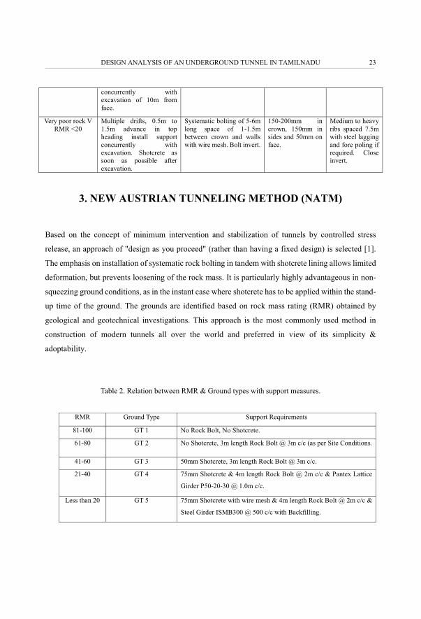
INTERFACE ELEMENTS
Interface elements were arranged around the outer surface of the primary lining of the tunnel into the
surrounding rock by considering the rock-structure interaction. In the interfaces, the friction angle of
the surrounding rock was reduced by a factor Rinter which corresponds to 2/3�, where � is the friction
angle.
A. VANUVAMALAI, K.P. JAYA26
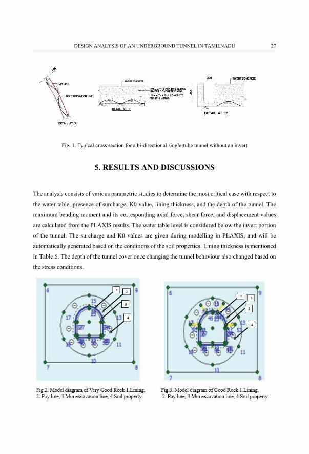
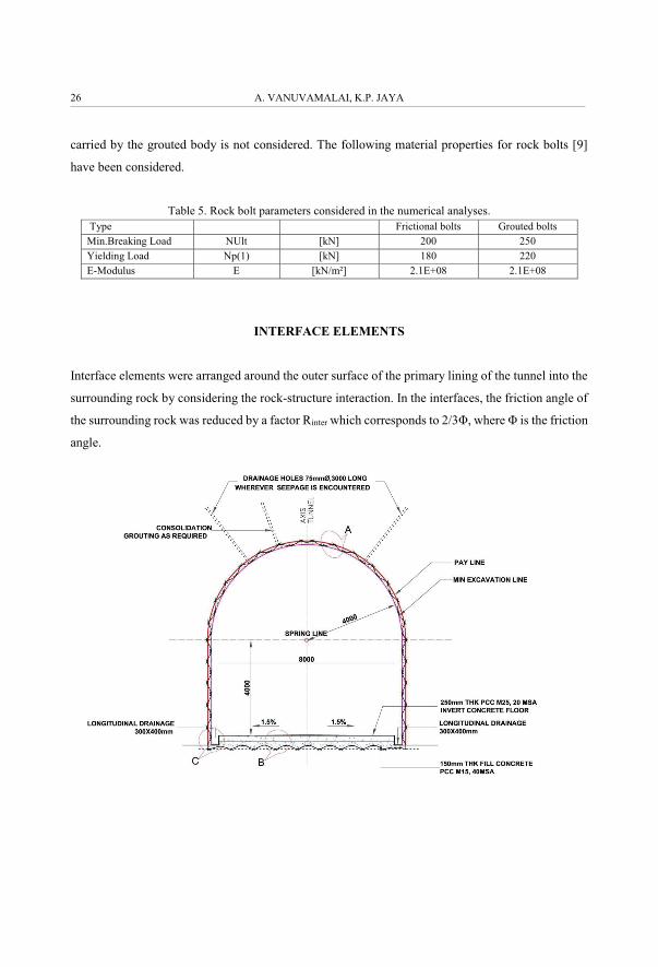
Fig. 1. Typical cross section for a bi-directional single-tube tunnel without an invert
5. RESULTS AND DISCUSSIONS
The analysis consists of various parametric studies to determine the most critical case with respect to
the water table, presence of surcharge, K0 value, lining thickness, and the depth of the tunnel. The
maximum bending moment and its corresponding axial force, shear force, and displacement values
are calculated from the PLAXIS results. The water table level is considered below the invert portion
of the tunnel. The surcharge and K0 values are given during modelling in PLAXIS, and will be
automatically generated based on the conditions of the soil properties. Lining thickness is mentioned
in Table 6. The depth of the tunnel cover once changing the tunnel behaviour also changed based on
the stress conditions.
DESIGN ANALYSIS OF AN UNDERGROUND TUNNEL IN TAMILNADU 27

A. VANUVAMALAI, K.P. JAYA28

DESIGN ANALYSIS OF AN UNDERGROUND TUNNEL IN TAMILNADU 29

A. VANUVAMALAI, K.P. JAYA30
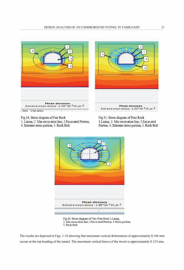
The results are depicted in Figs. 1-16 showing that maximum vertical deformation of approximately 0.166 mm
occurs at the top heading of the tunnel. The maximum vertical heave of the invert is approximately 0.133 mm.
DESIGN ANALYSIS OF AN UNDERGROUND TUNNEL IN TAMILNADU 31

The maximum horizontal deformation at the lower part of the bench is approximately 0.11 mm, occurring in
very good, good, and fair rock conditions. The maximum in poor and very poor rock conditions is 0.619 mm
and 13 mm.
A. VANUVAMALAI, K.P. JAYA32

Figs. 23-25 show bending moments of the primary lining (final step). Figs. 17-22 show the internal
forces of the final calculation step. A maximum normal force of approximately 108 KN and 1002 KN
is determined for the primary lining. Due to the closure of the primary lining, no singularities occur
in this numerical analysis. The maximum bending moments are determined to be about 0.316 kNm
DESIGN ANALYSIS OF AN UNDERGROUND TUNNEL IN TAMILNADU 33
and 19 kNm, respectively. The primary lining is designed in sections by providing radial bolting in
the rock bolts of the final calculation step. It can be observed that the rock bolts reach the ultimate
level in most parts of the tunnel. For the analyses, the correlation between ground types, behaviour
types, ranges of overburden, and support categories are investigated, as shown in Table 6. Fault zones
are not calculated via the simple analytical method due to the limited thickness of the fault zone,
which leads to significantly lower displacements and loading of the tunnel lining than in the 2D
analysis.
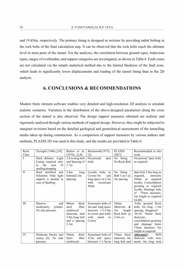
6. CONCLUSIONS & RECOMMENDATIONS
Modern finite element software enables very detailed and high-resolution 2D analysis to simulate
realistic scenarios. Variation in the distribution of the above-designed parameters along the cross
section of the tunnel is also observed. The design support measures obtained are realistic and
rigorously analysed through various methods of support design. However, they might be subjected to
marginal revisions based on the detailed geological and geotechnical assessments of the tunnelling
media taken up during construction. As a comparison of support measures by various authors and
methods, PLAXIS 2D was used in this study, and the results are provided in Table 6:
Rock Class
Terzaghi (1946).,[10] Barton et al. (1974)., [2,8]
Bieniawski(1973)., [3]
PLAXIS 2D[7]
Recommended in this work
I Hard &Intact. Light Lining required only in the case of spalling/popping
3.8 m long bolt and Spacing of 2.7m
Occasional spot bolts
No lining / No Rock Bolt
Occasional Spot bolts as required
II Hard stratified and Schistose. Only light support is needed in case of Spalling
3.8m long boltand2.5m Spacing
Locally bolts in Crown-3m and long space of 2.5m with occasional Mesh
No lining / Bolt 3 no’s @ 3m spacing
Spot bolt 3.0m long as required, shotcrete 50mm as required locally, Consolidation grouting as required locally, Drainage hole of 75mm diameter, 3m length as required locally
III Massive and moderately jointed. No side pressure.
40mm thick steel fiber reinforced shotcrete. And 3.8m long bolt and a spacing 2.3m
Systematic bolts of 4m and long space between 1.5-2.0m in crown and walls with mesh in Crown
50mm Shotcrete & 3m length Rock Bolt @ 2.5m c/c
Fully grouted Rock bolts 3m long, 1.5m spacing, Staggered M-30, 50mm thick shotcrete, consolidation grouting and drainage holes 75mm diameter, 3m length as required.
IV Moderate blocky and seamy [6]. No side pressure
50mm thick Steel fiber reinforced
Systematic bolts of 4-5m and space between 1-1.5m in
75mm thick shotcrete, 4m long bolt and
Alternate1: M30 shotcrete with wire mesh, 4m long rock
A. VANUVAMALAI, K.P. JAYA34

shotcrete with3.8m long bolts and Spacing of 1.5m
crown and walls with wire mesh
2m spacing bolt, spacing at 2.0m with lattice girder P50-20-30 @ 1.0M C/C Alternate2: 75mm shotcrete with wire mesh and ISMB 300 @ 1.00mmC/C, Rock bolt 4m @1.50m c/c
V Very blocky and seamy. Little or no side pressure
120-150mm shotcrete Steel fibers with 3.8m long bolts at a spacing of 1.2m
Systematic bolts of 5-6m and space between 1-1.5m in Crown and walls with wire mesh. Bolt invert
75mm thick shotcrete, 4m long, @2m spacing
Shotcrete 75Mm thick with wire mesh, 5m long bolts at a spacing of 1.5m & Steel girder ISMB 300× 140@ 500mmc/c
A thorough comparison of supports across various methods prevalent in general practice using
conventional wisdom is also considered for the final support measures. As the superincumbent load
is below 500m in competent media, no overstressing or squeezing conditions are discussed. This
study is based on the detailed design carried out by collecting field data and applied data, however,
variations will be encountered during the actual tunneling process. As a compromise, conducting in
situ tests is recommended as a pre-construction activity in order to obtain more realistic conditions,
and also to validate the present design work which was carried out based primarily on lab data.
ACKNOWLEDGEMENTS
The first author acknowledges the financial assistance provided by Anna University, Chennai, through
the Anna Centenary Research Fellowship research grant and would also like to thank
Mr.V.Balachandran, GSI Retd, (HoD), Chennai, for his moral support.
DESIGN ANALYSIS OF AN UNDERGROUND TUNNEL IN TAMILNADU 35

REFERENCES
1. Austrian Society for Geomechanics, Guideline for the geotechnical design of underground structures with conventional excavation. 2001, 2008, 2009.
2. Barton, N. Lien., and Lunde J. (1974). Engineering classification of Rock masses for the Design of tunnel Supports, Rock Mechanics Springer-Vertag vol.6.
3. Bieniawski, Z.T. (1973). Engineering Classification of Jointed Rock masses, The Civil Engineer in South Africa. 4. Bieniawski, Z.T. (1979).the Geomechanics Classification in Rock Engineering Applications, Intl.Soc. For Rock.
Mech. 5. Bieniawski, Z.T. (1989). Engineering Rock Mass Classification John Wiley &sons. 6. Brekke, T.L. (1968). Blocky and seamy rock in tunnelling Bull.Assoc.Eng.Geol Vol.5. 7. Brinkgreve R.B.J. et al., (2002), PLAXIS 2D- Version 8 User Manual, A.A. Balkema Publishers. 8. Grimstad, E. and Barton, N. (1993) Updating of the Q system for NMT-Intl symposium on sprayed concrete-
Modern use of wet mix sprayed concrete for underground support. 9. Hoek, E. and Brown, E.T. (1982). Underground excavation in rocks Institution of Mining and Metallurgy,
London. 10. Terzhagi, K. (1946). Rock defects and load on tunnel supports, Introduction to Rock tunnelling with steel
supports published by Proctor, Ohio, USA.
A. VANUVAMALAI, K.P. JAYA36
LIST OF FIGURES AND TABLES:
Fig. 1. Typical cross section for bi-directional single tube tunnel without invert
Rys. 1. Typowy przekrój dla dwukierunkowego tunelu z pojedyncz� rur�, bez odwracania
Fig.2. Model diagram of Very Good Rock
Rys. 2. Wzorcowy wykres bardzo dobrej skały
Fig.3. Model diagram of Good Rock
Rys. 3. Wzorcowy wykres dobrej skały
Fig.4. Model diagram of Fair Rock
Rys. 4. Wzorcowy wykres przeci�tnej skały
Fig.5. Model diagram of Poor Rock
Rys. 5. Wzorcowy wykres słabej skały
Fig.6. Model diagram of Very Poor Rock
Rys. 6. Wzorcowy wykres bardzo słabej skały
Fig.7. Displacement diagram of Very Good Rock
Rys. 7. Wykres przemieszczenia bardzo dobrej skały
Fig.8. Displacement diagram of Good Rock
Rys. 8. Wykres przemieszczenia dobrej skały
Fig.9. Displacement diagram of Fair Rock
Rys. 9. Wykres przemieszczenia przeci�tnej skały
Fig.10.Displacement diagram of poor Rock
Rys. 10.Wykres przemieszczenia słabej skały
Fig.11.Displacement diagram of Very poor Rock
Rys. 11.Wykres przemieszczenia bardzo słabej skały
Fig.12. Stress diagram of Very good Rock
Rys. 12. Wykres napr��e� bardzo dobrej skały
Fig.13. Stress diagram of good Rock
Rys. 13. Wykres napr��e� dobrej skały
Fig.14. Stress diagram of fair Rock
Rys. 14. Wykres napr��e� przeci�tnej skały
Fig.15. Stress diagram of poor Rock
Rys. 15. Wykres napr��e� słabej skały
Fig.16. Stress diagram of Very poor Rock
Rys. 16. Wykres napr��e� bardzo słabej skały
Fig.17.Figure shows Fair Rock Axial force
Rys. 17. Rysunek przedstawiaj�cy sił� osiow� przeci�tnej skały
Fig.18.Figure shows poor Rock Axial force
DESIGN ANALYSIS OF AN UNDERGROUND TUNNEL IN TAMILNADU 37

Rys. 18. Rysunek przedstawiaj�cy sił� osiow� słabej skały
Fig.19.Figure shows very poor Rock Axial force
Rys. 19. Rysunek przedstawiaj�cy sił� osiow� bardzo słabej skały
Fig.20.Figure shows Fair Rock shear force
Rys. 20. Rysunek przedstawiaj�cy sił� cinaj�c� przeci�tnej skały
Fig.21.Figure shows poor Rock shear force
Rys. 21. Rysunek przedstawiaj�cy sił� cinaj�c� słabej skały
Fig.22.Figure shows very poor Rock shear force
Rys. 22. Rysunek przedstawiaj�cy sił� cinaj�c� bardzo słabej skały
Fig.23.Figure shows Fair Rock Bending Moment
Rys. 23. Rysunek przedstawiaj�cy moment zginaj�cy przeci�tnej skały
Fig.24. Figure shows Poor Rock Bending Moment
Rys. 24. Rysunek przedstawiaj�cy moment zginaj�cy słabej skały
Fig.25. Figure shows Very Poor Rock Bending Moment
Rys. 25. Rysunek przedstawiaj�cy moment zginaj�cy bardzo słabej skały
Received 15.05.2017 Revised 26.02.2018
A. VANUVAMALAI, K.P. JAYA38

ANALIZA PROJEKTOWA TUNELU PODZIEMNEGO W TAMILNADU
Słowa kluczowe: Technologia przestrzeni podziemnej, RMR, Projekt, rodki wsparcia, Plaxis 2D.
STRESZCZENIE:
W ostatnim czasie technologia przestrzeni lub podziemne struktury zyskały na znaczeniu na całym wiecie. Sukces w
realizacji takich przedsi�wzi�� zale�y od dokładnego i realistycznego projektu, który nie jest ani optymistyczny, ani
konserwatywny, a niezwykle potrzeby jest obecnie zbalansowany projekt. W niniejszej pracy przedstawiono badanie
porównawcze dotycz�ce projektu wsparcia, takie jak teoria obci��enia Terzhagiego oraz ilociowe metody jakoci
orodka skalnego (Q), oceny orodka skalnego według Bieniawskiego oraz modelowanie numeryczne Plaxis 2D.
Uzyskane wyniki pokazuj�, �e ko�cowe rodki wsparcia, takie jak torkretowanie, grubo�, przebijanie skał, kotwienie,
długo�, cz�stotliwo�, wymagania w zakresie stalowych podpór, s� lepsze. Na podstawie os�dów in�ynieryjnych i
podej� analitycznych uzyskano realistyczne rodki wsparcia dla tunelu dost�powego, który ma zosta� wykopany w
Nilagiri, Tamil Nadu.
Nowoczesne oprogramowanie elementów sko�czonych umo�liwia przeprowadzenie bardzo szczegółowej analizy 2D o
wysokiej rozdzielczoci dla realistycznych scenariuszy. Obserwuje si� równie� zmian� w rozkładzie powy�szego
parametru projektowego wzdłu� przekroju poprzecznego tunelu. Przyj�te rodki wsparcia projektowego s� realistyczne i
s� analizowane za pomoc� ró�nych metod projektowania podpór. Mog� one jednak zosta� poddane nieznacznej korekcie
w oparciu o szczegółow� geologiczn� i geotechniczn� ocen� dr��enia tunelu, któr� nale�y przeprowadzi� podczas
budowy. W badaniu zastosowano porównanie rodków wsparcia przez ró�nych autorów i za pomoc� ró�nych metod oraz
Plaxis 2D. Dokładne porównanie podpór za pomoc� ró�nych metod dominuj�cych w powszechnej praktyce pod
wzgl�dem konwencjonalnych przekona� równie� wpłyn�ło na ko�cowe rodki wsparcia. Ze wzgl�du na fakt, i� zwisaj�cy
ładunek znajduje si� na wysokoci poni�ej 500 metrów nad właciwym podło�em, nie omówiono �adnych warunków
przeci��ania ani ciskania. Badanie to opiera si� na szczegółowym projekcie realizowanym poprzez zbieranie danych
terenowych oraz stosowanych danych. Jednak wariacje zostan� spełnione podczas rzeczywistego dr��enia tunelu. W
ramach kompromisu zalecono przeprowadzenie bada� w pierwotnym miejscu jako wst�pnych działa� budowlanych
� �������� ������������ ����� ��������� ������������� ���!"�#� tak�e, aby przede wszystkim sprawdzi� obecne prace
projektowe wykonywane w oparciu o dane laboratoryjne.
DESIGN ANALYSIS OF AN UNDERGROUND TUNNEL IN TAMILNADU 39