Embed Size (px)
Citation preview

Design a drill jig for drilling 4 holes in the following component.

Design procedure for Jiga. Selection of Jig
A leaf (or) latch jig is selected to accomplish this component. The leaf is hinged on one side of jig body by hinges.
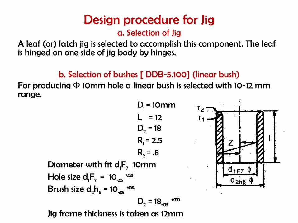
b. Selection of bushes [ DDB-5.100] (linear bush)For producing 10mm hole a linear bush is selected with 10-12 mm Фrange.
D1 = 10mm
L = 12D2 = 18R1 = 2.5R2 = .8
Diameter with fit d1F7 10mmHole size d1F7 = 10-.06
+.024
Brush size d2h6 = 10-.06+.024
D2 = 18-.013+.000
Jig frame thickness is taken as 12mm
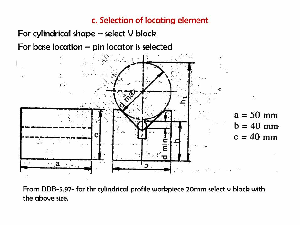
c. Selection of locating element
For cylindrical shape – select V block
For base location – pin locator is selected
From DDB-5.97- for thr cylindrical profile workpiece 20mm select v block with the above size.
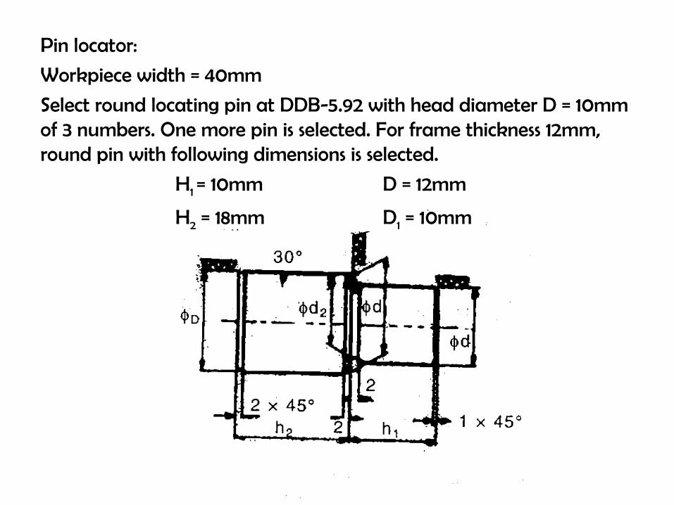
Pin locator:
Workpiece width = 40mm
Select round locating pin at DDB-5.92 with head diameter D = 10mm of 3 numbers. One more pin is selected. For frame thickness 12mm, round pin with following dimensions is selected.
H1 = 10mm D = 12mm
H2 = 18mm D1 = 10mm
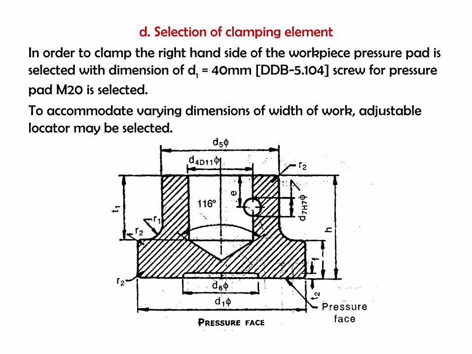
d. Selection of clamping element
In order to clamp the right hand side of the workpiece pressure pad is selected with dimension of d1 = 40mm [DDB-5.104] screw for pressure pad M20 is selected.
To accommodate varying dimensions of width of work, adjustable locator may be selected.
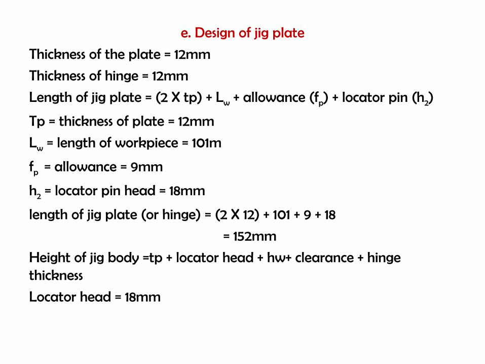
e. Design of jig plate
Thickness of the plate = 12mm
Thickness of hinge = 12mm
Length of jig plate = (2 X tp) + Lw + allowance (fp) + locator pin (h2)
Tp = thickness of plate = 12mm
Lw = length of workpiece = 101m
fp = allowance = 9mm
h2 = locator pin head = 18mm
length of jig plate (or hinge) = (2 X 12) + 101 + 9 + 18
= 152mm
Height of jig body =tp + locator head + hw+ clearance + hinge thickness
Locator head = 18mm
Height of workpiece = 10+30+10 = 50mm
Clearance (workpiece is assumed as casting)(brittle material)
Clearance = drill diameter
= 10mm
Hinge thickness and plate thickness = 12mm
Height of jig body without jig feet = 12+18+50+10+12
=102mm
Hinge is to be fabricated
Length = 152mm
Thickness = 12mm
Quarter turn screw can be used for easy operation

f. Selection of jig feet (or) jig buttonInorder to place drill jig, jig button should be at the bottom. Dimension h = 5mm [DDB-5.98] Material : case hardened – C45Tensile strength , бu = 520 N/mm2
Hardness = 45-50 RCSurface finish = .025mm to .05 mm
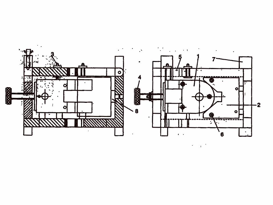
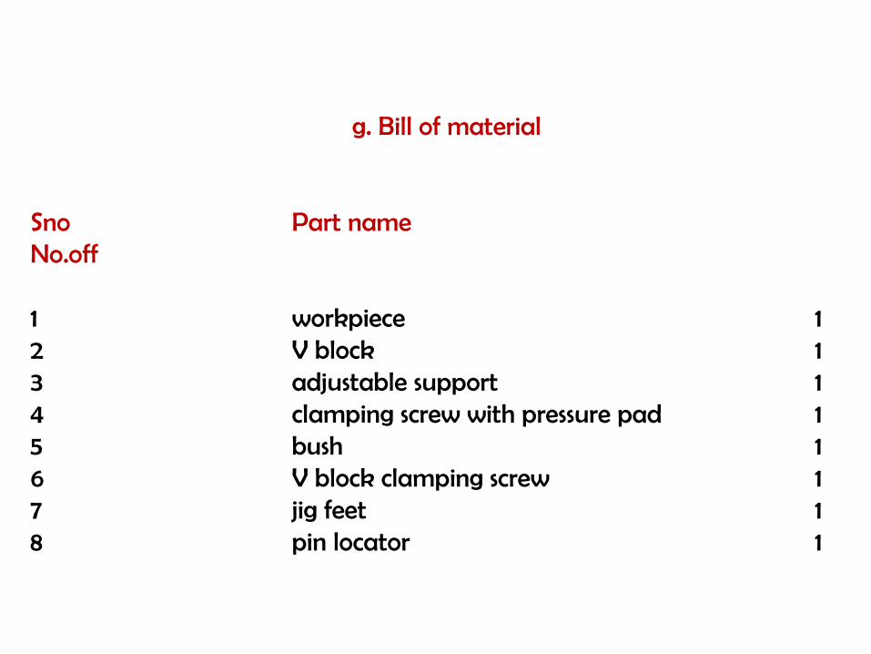
g. Bill of material
Sno Part nameNo.off
1 workpiece 12 V block 13 adjustable support 14 clamping screw with pressure pad 15 bush 16 V block clamping screw 17 jig feet 18 pin locator 1
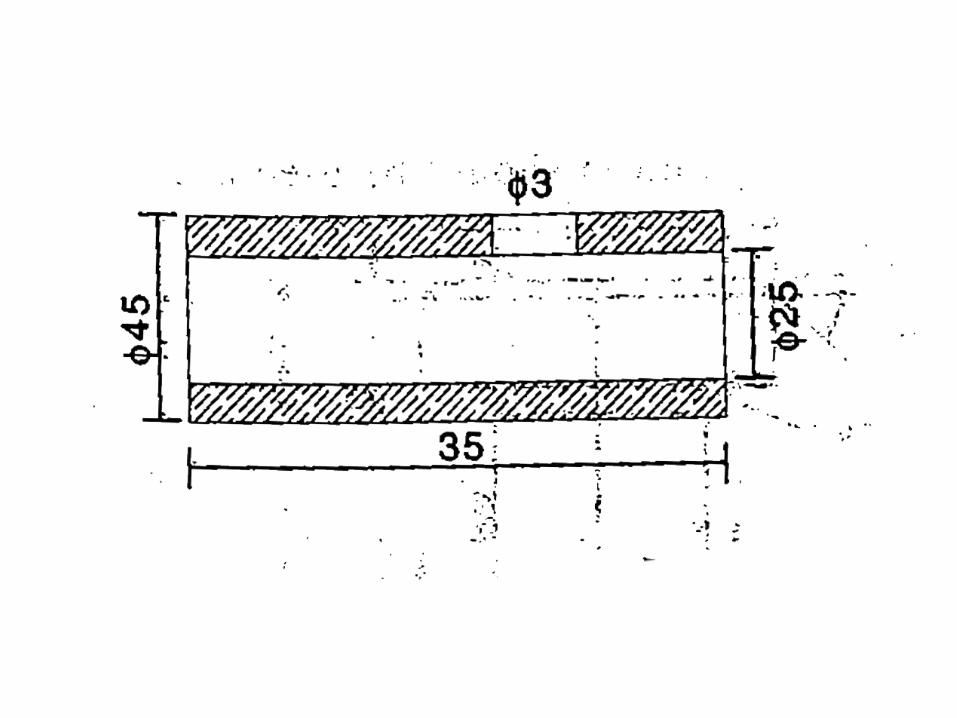
Design a drill jig for drilling an oil hole of size 3mm for the given job as in figure.
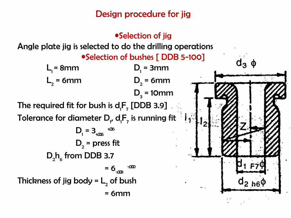
Design procedure for jig
•Selection of jigAngle plate jig is selected to do the drilling operations
•Selection of bushes [ DDB 5-100]L1 = 8mm D1 = 3mm
L2 = 6mm D2 = 6mm
D3 = 10mm
The required fit for bush is d1F7 [DDB 3.9]
Tolerance for diameter D1, d1F7 is running fit
D1 = 3+.006+.016
D2 = press fit
D2h6 from DDB 3.7
= 6-.009-.000
Thickness of jig body = L2 of bush
= 6mm

c. Jig body (casted body)
Base length of jig body may be selected as 3 times the length of the workpiece for better rigidity.
Base length Lb = 3 X 35 =105 mm
Thickness of jig body = 6mmThe working height h2 of the jig body is approximately equal to 1.5 to 2 times outer dia of workpiece.
H2 = 2X45 = 90mm
Ht = 2tp + h2 (including clearance) + (2X6) + 90
Ht = 102mm
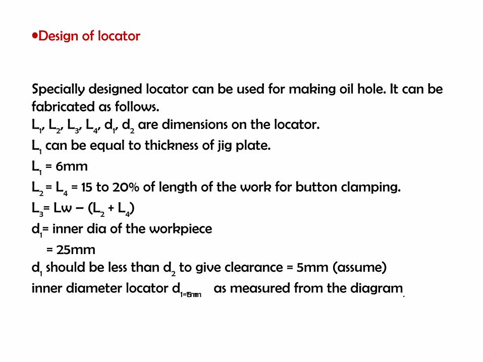
•Design of locator
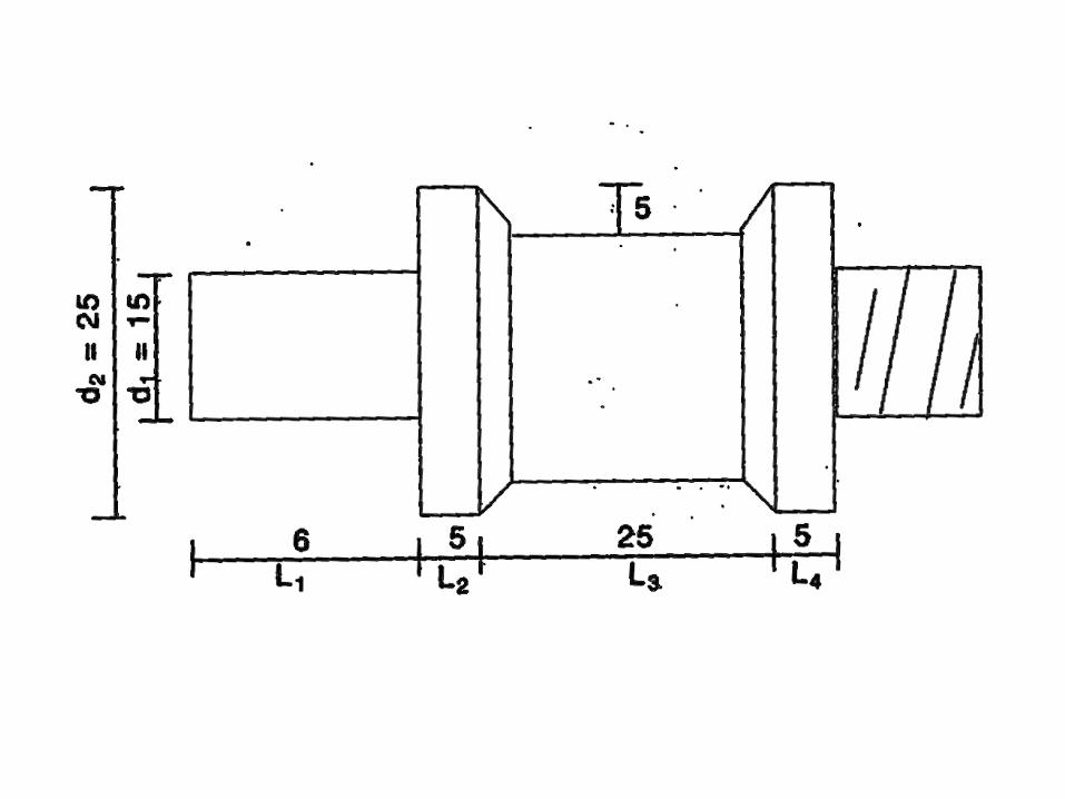
Specially designed locator can be used for making oil hole. It can be fabricated as follows.L1, L2, L3, L4, d1, d2 are dimensions on the locator.
L1 can be equal to thickness of jig plate.
L1 = 6mm
L2 = L4 = 15 to 20% of length of the work for button clamping.
L3= Lw – (L2 + L4)
d1= inner dia of the workpiece
= 25mmd1 should be less than d2 to give clearance = 5mm (assume)
inner diameter locator d1 = 15mm as measured from the diagram.
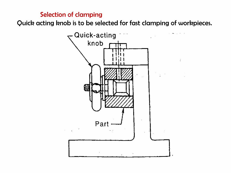
Selection of clampingQuick acting knob is to be selected for fast clamping of workpieces.
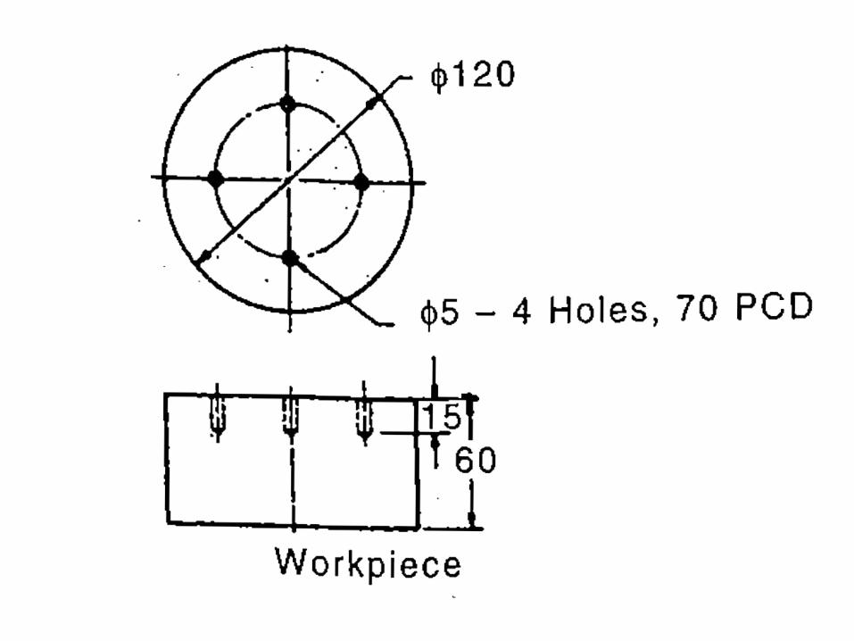
Design and draw jig for mild steel component shown in figure to drill 4 holes of 5mm diameter
at 70 P.C.D
Design procedure for a jig
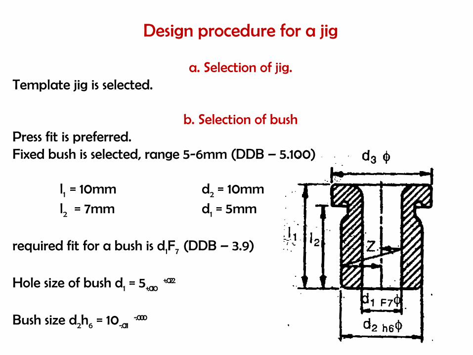
a. Selection of jig.Template jig is selected.
b. Selection of bushPress fit is preferred.Fixed bush is selected, range 5-6mm (DDB – 5.100)
l1 = 10mm d2 = 10mml2 = 7mm d1 = 5mm
required fit for a bush is d1F7 (DDB – 3.9) Hole size of bush d1 = 5+.010
+.022
Bush size d2h6 = 10-.011-.000
Thickness of frame work = 7mm which is equal to l2 of bush
Material : case hardened C45
Tensile strength бu = 520 N/mm2
Hardness = 229 BHN
Surface finish = .025mm to .05mm
Bush material- high carbon steel – hardening 60 +_ 2 RC

c. Selection of locator
Nesting locator is selected because vertical cylinder is to be drilled.
Size 240X240X60 mm
d. Template design (to be fabricated)
Size 170X240X60 mm
e. Selection of clamping nut (DDB 5.81)
M8X1 is selected.
f. T- bolt
12X50 is to be fabricated.Ф
![Seat No.: Enrolment No. GUJARAT TECHNOLOGICAL UNIVERSITYgtu-info.com/Files/ExamPapersOther/DE/2117/3361902.pdf · a] Select suitable drill jig to drill 2 holes of 10 mm diameter and](https://img.dokumen.tips/doc/110x75/5e7b206a0f8e8a233267326e/seat-no-enrolment-no-gujarat-technological-universitygtu-infocomfilesexampapersotherde2117.jpg)

![Development of Flexible Drilling Jig for Wing-Fuselage ... · Wiemann [5] introduced a flexible template for drill units which can be pinned into piloted datum holes, allowing the](https://img.dokumen.tips/doc/110x75/5cad8fe488c993ab5e8b6c32/development-of-flexible-drilling-jig-for-wing-fuselage-wiemann-5-introduced.jpg)