Embed Size (px)
Citation preview
USER INSTRUCTIONSGC09/12
Universal Dowelling Jig SetModel No: CDJ-2
Part No: 6462124

2
Parts & Service: 020 8988 7400/E-mail:[email protected] or [email protected]
INTRODUCTION
Thank you for purchasing this CLARKE Dowel Jig Set.
Please read and follow the instructions carefully. In doing so you will ensurethe safety of yourself and others around you, and you can look forward to theproduct giving you long & satisfactory service.
Please keep these instructions in a safe place for future reference
GUARANTEEThis product is guaranteed against faulty manufacture for a period of 12months from the date of purchase. Please keep your receipt which will berequired as proof of purchase.
This guarantee is invalid if the product is found to have been abused ortampered with in any way, or not used for its intended purpose. Faulty goodsshould be returned to their place of purchase. No product can be returned tous without prior permission.
This guarantee does not effect your statutory rights.
3
Parts & Service: 020 8988 7400/E-mail:[email protected] or [email protected]
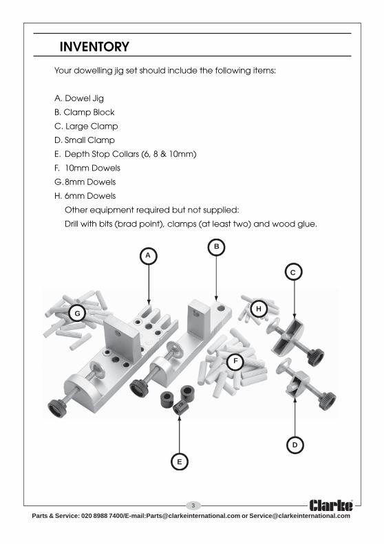
INVENTORY
Your dowelling jig set should include the following items:
A. Dowel Jig
B. Clamp Block
C. Large Clamp
D. Small Clamp
E. Depth Stop Collars (6, 8 & 10mm)
F. 10mm Dowels
G.8mm Dowels
H. 6mm Dowels
Other equipment required but not supplied:
Drill with bits (brad point), clamps (at least two) and wood glue.
AB
C
D
E
F
GH

4
Parts & Service: 020 8988 7400/E-mail:[email protected] or [email protected]
SAFETY PRECAUTIONS
1. ALWAYS learn the equipment’s applications, limitations and the specificpotential hazards peculiar to it. Read and become familiar with the entireoperating manual.
2. ALWAYS use a face or dust mask if operation is particularly dusty.
3. ALWAYS check for damage. Before using tools and equipment, anydamaged part, should be checked to ensure that it will properly performits intended function. Check for alignment of parts, breakage of parts,mountings and any other condition that may affect the tools operation.Any damage should be properly repaired or the part replaced. If in doubt,DO NOT use the tool. Consult your local dealer.
4. ALWAYS keep work area clean. Cluttered areas and benches inviteaccidents.
5. ALWAYS ensure that adequate lighting is available. A minimum intensity of300 lux should be provided. Ensure that lighting is placed so that you willnot be working in your own shadow.
6. ALWAYS keep children away. All visitors should be kept a safe distancefrom the work area, especially whilst operating the equipment.
7. ALWAYS maintain tools in top condition. Keep tools/machines clean for thebest and safest performance. Follow maintenance instructions.
8. ALWAYS concentrate on the job in hand, no matter how trivial it mayseem. Be aware that accidents are caused by carelessness due tofamiliarity.
9. ALWAYS keep your proper footing and balance at all times - don’toverreach. For best footing, wear rubber soled footwear. Keep floor clearof oil, scrap wood, etc
5
Parts & Service: 020 8988 7400/E-mail:[email protected] or [email protected]
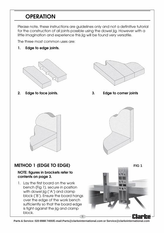
OPERATION
Please note, these instructions are guidelines only and not a definitive tutorialfor the construction of all joints possible using the dowel jig. However with alittle imagination and experience this jig will be found very versatile.
The three most common uses are:
1. Edge to edge joints.
2. Edge to face joints. 3. Edge to corner joints
METHOD 1 (EDGE TO EDGE)NOTE: figures in brackets refer tocontents on page 3.
1. Lay the first board on the workbench (Fig 1), secure in positionwith dowel jig (‘A’) and clampblock (‘B’). Ensure the board hangsover the edge of the work benchsufficiently so that the board edgeis tight against the jig and clampblock.
FIG 1

6
Parts & Service: 020 8988 7400/E-mail:[email protected] or [email protected]
Place second board onto jig (Fig. 2),ensure as before, the board edge istight against the jig and clampblock, also line up the ends andsecure with upper clamps.
DO NOT over-tighten clamps.
The next step is to choose the dowelsize.
The size of dowels to be used is mainlydependant on the board thickness.Determine which of the three holes linesup closest to the centre of the board(example Fig. 3 shows a 6mm dowel isrequired). NOTE: diagram is forillustrative purposes only.
When the dowel size is decided (in thisexample 8mm), slide the 8mm depth stoponto the equivalent drill.
The position of the stop is determined by thetype of joint and the length of the dowelused. in this example, edge to edge, thedowels will be required to be insertedequally into both pieces to be joined.Measure the length of the dowel (average= 37mm), divide by 2, = 18.5.
Insert the drill into the 8mm guide so that19mm protrudes through the jig. (Fig. 4), thisensures the dowels will not bottom andprevent the boards from meeting whenjoining together.
Slide the depth stop up to the jig bodywithout moving the drill, lock in position,check the drill still protrudes 19mm, if not re-adjust.
FIG 2
FIG 3
FIG 4
19mm
8mm 6mm
10mm
7
Parts & Service: 020 8988 7400/E-mail:[email protected] or [email protected]
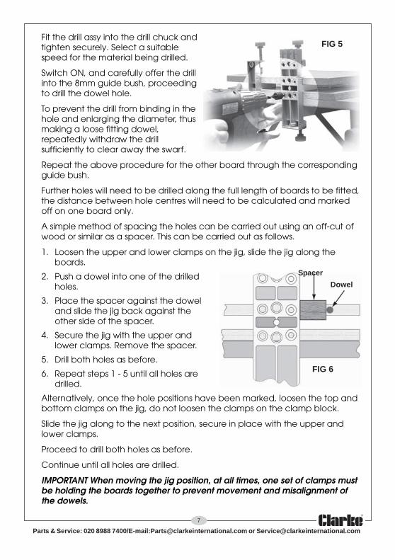
Fit the drill assy into the drill chuck andtighten securely. Select a suitablespeed for the material being drilled.
Switch ON, and carefully offer the drillinto the 8mm guide bush, proceedingto drill the dowel hole.
To prevent the drill from binding in thehole and enlarging the diameter, thusmaking a loose fitting dowel,repeatedly withdraw the drillsufficiently to clear away the swarf.
Repeat the above procedure for the other board through the correspondingguide bush.
Further holes will need to be drilled along the full length of boards to be fitted,the distance between hole centres will need to be calculated and markedoff on one board only.
A simple method of spacing the holes can be carried out using an off-cut ofwood or similar as a spacer. This can be carried out as follows.
1. Loosen the upper and lower clamps on the jig, slide the jig along theboards.
2. Push a dowel into one of the drilledholes.
3. Place the spacer against the doweland slide the jig back against theother side of the spacer.
4. Secure the jig with the upper andlower clamps. Remove the spacer.
5. Drill both holes as before.
6. Repeat steps 1 - 5 until all holes aredrilled.
Alternatively, once the hole positions have been marked, loosen the top andbottom clamps on the jig, do not loosen the clamps on the clamp block.
Slide the jig along to the next position, secure in place with the upper andlower clamps.
Proceed to drill both holes as before.
Continue until all holes are drilled.
IMPORTANT When moving the jig position, at all times, one set of clamps mustbe holding the boards together to prevent movement and misalignment ofthe dowels.
FIG 5
FIG 6
Dowel
Spacer

8
Parts & Service: 020 8988 7400/E-mail:[email protected] or [email protected]
METHOD 2 (EDGE TO CORNER)The procedure for this joint is very similar to theedge to edge joint.
The first board is clamped to the workbench inexactly the same way (Fig. 1).
The second board is stood on its edge as in Fig 7with the upper clamps from behind, see Fig 8.
Two hole depths are required when drilling dowelholes in edge to corner joints. The depth stop positions are determined by theboard thickness as follows:
The vertical board (Fig. 8 ‘A’)
1. Measure the board thickness (15mm),calculate two thirds = 10mm, this is the depthof hole to be drilled in the board surface.
2. Slide the depth stop onto the relevant drill bitand adjust as before (Fig. 4), this time only10mm protrudes through the jig.
The horizontal board (Fig. 8 ‘B’)
Based on the dowels being 37mm in length, theholes need to be 27mm + 1mm deep to ensurethe dowels do not bottom, thus preventing theboards meeting properly.
Adjust the depth stop so that the drill protrudes28mm through the jig.
1. Drill all holes in the horizontal board,withdrawing it regularly to clear any swarf.
2. Re-adjust the depth stop to 10mm and drill allholes in the vertical board.
Board thickness (15mmin this example)
FIG 9
FIG 8
FIG 7
A
B

9
Parts & Service: 020 8988 7400/E-mail:[email protected] or [email protected]
METHOD 3 (EDGE TO SURFACE)The procedure for this joint is very similarto the edge to corner joint.
The first board is clamped to theworkbench in exactly the same way(Fig. 1). The drilling depths arecalculated as above.
1. Adjust the depth stop to 28mm, drillall holes in horizontal board.
2. Re-adjust the depth stop to 10mm,put safely to one side.
3. Mark a centre line on the second board where the boards are to bejoined.
4. Lay the first board on top of the second board (Fig 10) and loosely clampin position.
5. Place jig on one end of the second board (Fig 11), adjust the position ofthe first board until the centre line can be viewed in the dead centre ofthe relevant guide bush.
7. Check drill is still set to 10mm(step 2). Locate the jig onprotruding dowels using thecorresponding slot to theguidebush being used for drilling(8mm) see Fig 12. Drill all holes insecond board ensuring the jig isheld square and firmly againstthe edge of the first board.
FIG 10
FIG 12
FIG 11
Second Board
Centre line
First Board
‘A’ ‘B’
6. Move the jig to other endand line up as above,keep repeating steps 5and 6 until ‘A’ equals ‘B’.Carefully secure inposition with ‘G’ clampsor similar, recheck ‘A’ and‘B’ are still equal, if not,re-adjust before starting.
NOTE: keep the jig sqaure to theedge of the first board at all timeswhen using in this mode.

10
Parts & Service: 020 8988 7400/E-mail:[email protected] or [email protected]
NOTES
___________________________________________________________________________
___________________________________________________________________________
___________________________________________________________________________
___________________________________________________________________________
___________________________________________________________________________
___________________________________________________________________________
___________________________________________________________________________
___________________________________________________________________________
___________________________________________________________________________
___________________________________________________________________________
___________________________________________________________________________
___________________________________________________________________________
___________________________________________________________________________
___________________________________________________________________________

11
Parts & Service: 020 8988 7400/E-mail:[email protected] or [email protected]
NOTES
___________________________________________________________________________
___________________________________________________________________________
___________________________________________________________________________
___________________________________________________________________________
___________________________________________________________________________
___________________________________________________________________________
___________________________________________________________________________
___________________________________________________________________________
___________________________________________________________________________
___________________________________________________________________________
___________________________________________________________________________
___________________________________________________________________________
___________________________________________________________________________
___________________________________________________________________________