Embed Size (px)
Citation preview
DESCO Air Hat Service Manual
Section1. DESCO Air Hat Owners Manual2. Sub-Assemblies, Installation & Servicing3. Testing4. Report
DESCO CORPORATION240 N. MILWAUKEE STREETMILWAUKEE, WISCONSIN 53202PHONE 414-272-2371 FAX 414-272-2373E-Mail: [email protected] Catalog: www.divedesco.comDESCO Informational Website: www.descocorp.com
2012 DESCO Corporation
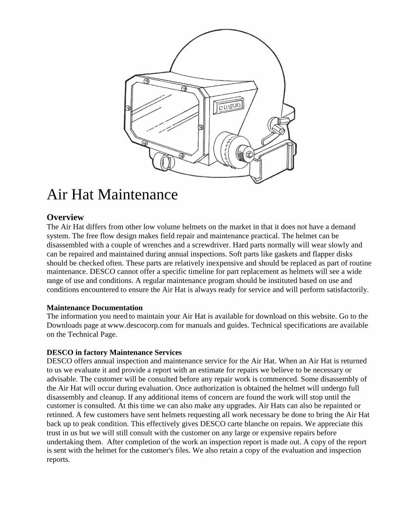
Air Hat MaintenanceOverviewThe Air Hat differs from other low volume helmets on the market in that it does not have a demandsystem. The free flow design makes field repair and maintenance practical. The helmet can bedisassembled with a couple of wrenches and a screwdriver. Hard parts normally will wear slowly andcan be repaired and maintained during annual inspections. Soft parts like gaskets and flapper disksshould be checked often. These parts are relatively inexpensive and should be replaced as part of routinemaintenance. DESCO cannot offer a specific timeline for part replacement as helmets will see a widerange of use and conditions. A regular maintenance program should be instituted based on use andconditions encountered to ensure the Air Hat is always ready for service and will perform satisfactorily.
Maintenance DocumentationThe information you need to maintain your Air Hat is available for download on this website. Go to theDownloads page at www.descocorp.com for manuals and guides. Technical specifications are availableon the Technical Page.
DESCO in factory Maintenance ServicesDESCO offers annual inspection and maintenance service for the Air Hat. When an Air Hat is returnedto us we evaluate it and provide a report with an estimate for repairs we believe to be necessary oradvisable. The customer will be consulted before any repair work is commenced. Some disassembly ofthe Air Hat will occur during evaluation. Once authorization is obtained the helmet will undergo fulldisassembly and cleanup. If any additional items of concern are found the work will stop until thecustomer is consulted. At this time we can also make any upgrades. Air Hats can also be repainted orretinned. A few customers have sent helmets requesting all work necessary be done to bring the Air Hatback up to peak condition. This effectively gives DESCO carte blanche on repairs. We appreciate thistrust in us but we will still consult with the customer on any large or expensive repairs beforeundertaking them. After completion of the work an inspection report is made out. A copy of the reportis sent with the helmet for the customer's files. We also retain a copy of the evaluation and inspectionreports.
DESCO AIR HATOWNERS MANUAL
This manual is supplied with all new DESCO Air Hats. General care andmaintenance guidelines are found in this manual.
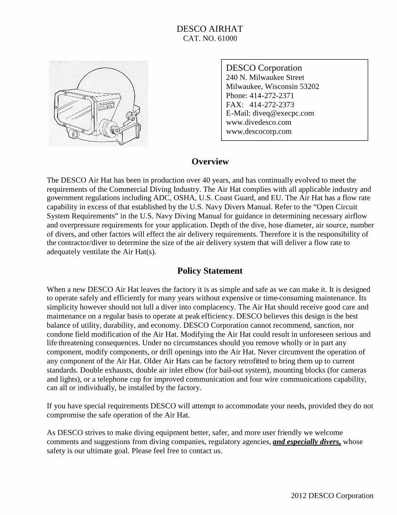
DESCO AIRHATCAT. NO. 61000
Overvie
The DESCO Air Hat has been in production over 40 yearequirements of the Commercial Diving Industry. The Agovernment regulations including ADC, OSHA, U.S. Cocapability in excess of that established by the U.S. NavySystem Requirements” in the U.S. Navy Diving Manualand overpressure requirements for your application. Depof divers, and other factors will effect the air delivery reqthe contractor/diver to determine the size of the air deliveadequately ventilate the Air Hat(s).
Policy State
When a new DESCO Air Hat leaves the factory it is as sto operate safely and efficiently for many years without esimplicity however should not lull a diver into complacemaintenance on a regular basis to operate at peak efficienbalance of utility, durability, and economy. DESCO Corcondone field modification of the Air Hat. Modifying thelife threatening consequences. Under no circumstances scomponent, modify components, or drill openings into thany component of the Air Hat. Older Air Hats can be facstandards. Double exhausts, double air inlet elbow (for band lights), or a telephone cup for improved communicacan all or individually, be installed by the factory.
If you have special requirements DESCO will attempt tocompromise the safe operation of the Air Hat.
As DESCO strives to make diving equipment better, safecomments and suggestions from diving companies, regusafety is our ultimate goal. Please feel free to contact us.
DESCO Corporation240 N. Milwaukee StreetMilwaukee, Wisconsin 53202Phone: 414-272-2371FAX: 414-272-2373E-Mail: [email protected]
w
rs, and has continually evolved to meet their Hat complies with all applicable industry andast Guard, and EU. The Air Hat has a flow rateDivers Manual. Refer to the “Open Circuitfor guidance in determining necessary airflowth of the dive, hose diameter, air source, numberuirements. Therefore it is the responsibility ofry system that will deliver a flow rate to
ment
imple and safe as we can make it. It is designedxpensive or time-consuming maintenance. Its
ncy. The Air Hat should receive good care andcy. DESCO believes this design is the best
poration cannot recommend, sanction, norAir Hat could result in unforeseen serious and
hould you remove wholly or in part anye Air Hat. Never circumvent the operation oftory retrofitted to bring them up to currentail-out system), mounting blocks (for camerastion and four wire communications capability,
accommodate your needs, provided they do not
r, and more user friendly we welcomelatory agencies, and especially divers, whose
2012 DESCO Corporation
Instructions for use and maintenance of the DESCO Air Hat.
Contents: PageSection 1. Instructions for use of the Air Hat. 1
Section 2. Maintenance of the DESCO Air Hat 5
Section 3. Helmet Disassembly 7
Section 4. Inspection of Air Hat Parts 9
Air Hat Exploded View 12
Air Hat Parts List 13
DESCO offers factory annual inspection services for the Air Hat. An evaluation is madeand recommendations are made on repairs and servicing necessary to certify the helmetas dive ready. Some DESCO dealers are also factory authorized to do annual inspectionsand repairs. Check with your dealer to see if they are part of this program.
DESCO is an importing distributor/dealer for Trelleborg Viking and Hunter Drysuits. Wecan provide a drysuit with a Viking or Hunter factory installed yoke ready to mate to theAir Hat.
Latest revision 08/29/12DESCO Corporation
Section 1. Instructions for use of the Air Hat.
Equipment Usable with the Air Hat: When attachment to a dry suit is not desired, the Air Hat can beused with the special DESCO neck dam, which provides a seal at the diver’s neck. The Air Hat can alsobe mated to a conventional commercial collar dress by means of the DESCO Neoprene Breastplate. Thisattaches to the dress in the same manner as a copper commercial breastplate but incorporates astretchable cylindrical collar, which is attached to the neck ring insert so as to make a seal with the AirHat. Similar use can be made of any dry suit, which comes equipped with such a collar.
Adjusting the Headpiece Insert for Head Size: Size adjustments to the headpiece assembly are madewith the assembly removed from the Air Hat. Loosen the two brass screws on the upper edge of the backplate at the rear of the assembly. The proper fit is achieved by changing the circumference of theheadpiece assembly, by sliding the back band in or out. The headpiece should fit snugly on the diver’shead, as the liner will compress somewhat under pressure. When the correct fit is achieved tighten thetwo screws and reinstall in the Air Hat.
How to Choose the Proper Size of Neck Dam: Neck Dams are available in sizes 12 through 15. Theappropriate size is approximately two sizes smaller than the diver’s regular collar size. Thus, a diverwho wears a size 16 collar should use a size 14 Neck Dam. Custom sized Neck Dams are available uponrequest.
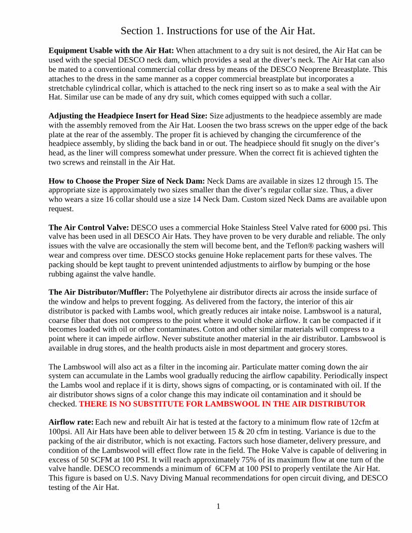
The Air Control Valve: DESCO uses a commercial Hoke Stainless Steel Valve rated for 6000 psi. Thisvalve has been used in all DESCO Air Hats. They have proven to be very durable and reliable. The onlyissues with the valve are occasionally the stem will become bent, and the Teflon® packing washers willwear and compress over time. DESCO stocks genuine Hoke replacement parts for these valves. Thepacking should be kept taught to prevent unintended adjustments to airflow by bumping or the hoserubbing against the valve handle.
The Air Distributor/Muffler: The Polyethylene air distributor directs air across the inside surface ofthe window and helps to prevent fogging. As delivered from the factory, the interior of this airdistributor is packed with Lambs wool, which greatly reduces air intake noise. Lambswool is a natural,coarse fiber that does not compress to the point where it would choke airflow. It can be compacted if itbecomes loaded with oil or other contaminates. Cotton and other similar materials will compress to apoint where it can impede airflow. Never substitute another material in the air distributor. Lambswool isavailable in drug stores, and the health products aisle in most department and grocery stores.
The Lambswool will also act as a filter in the incoming air. Particulate matter coming down the airsystem can accumulate in the Lambs wool gradually reducing the airflow capability. Periodically inspectthe Lambs wool and replace if it is dirty, shows signs of compacting, or is contaminated with oil. If theair distributor shows signs of a color change this may indicate oil contamination and it should bechecked. THERE IS NO SUBSTITUTE FOR LAMBSWOOL IN THE AIR DISTRIBUTOR
Airflow rate: Each new and rebuilt Air hat is tested at the factory to a minimum flow rate of 12cfm at100psi. All Air Hats have been able to deliver between 15 & 20 cfm in testing. Variance is due to thepacking of the air distributor, which is not exacting. Factors such hose diameter, delivery pressure, andcondition of the Lambswool will effect flow rate in the field. The Hoke Valve is capable of delivering inexcess of 50 SCFM at 100 PSI. It will reach approximately 75% of its maximum flow at one turn of thevalve handle. DESCO recommends a minimum of 6CFM at 100 PSI to properly ventilate the Air Hat.This figure is based on U.S. Navy Diving Manual recommendations for open circuit diving, and DESCOtesting of the Air Hat.
1
How to Minimize Air Intake Noise: Setting the Air Control Valve to provide sufficient airflow for theworkload will reduce airflow noise. At ¾ turn the Air Hat will deliver approximately 10cfm. In drybench testing by DESCO the sound level at full flow averaged 100db. Reducing the flow rate will cutdown the sound level. Testing showed that db will drop to about 94db at 10cfm. At 6.1cfm the soundlevel measured 88db. OSHA permissable continuous exposure to 90db is 8 hours; at 100db is 2 hours[1910.95(b) (2)].
Non-Return and Bail-out Non-Return Valves: The Non-Return valve on the Air Hat is standard9/16”- 18 Oxygen thread. The Bail-out Non-Return (marked with a letter ”B”) is drilled to accept aSCUBA whip from a Bail-out Bottle. A dust cap is provided on the Bail-out Non-Return to protect thethreads when not in use. The dust cap will provide some sealing but a complete airtight seal is notguaranteed. The integrity of the Non-returns can be tested by applying air pressure to the Air Hat withthe control valve fully closed, then removing the air supply hose, and applying a solution of dishwashingdetergent and water to the inlets. No air should leak back through the Non-Returns. If a leak is found theNon-Return disk may require replacement. This test method can be used on all connections in the airsupply train.
DESCO does not offer a suit inflator whip connection on the Air Hat. DESCO discourages using thebreathing gas supply for anything other than life support. Suit inflation should be accomplished by othermeans when using the Air Hat IMPORTANT SAFETY NOTE: Never add additional plumbing to eitherNon-return Valve or the air inlet elbow. The additional length increases the forces exerted on thesecomponents. Failure of the Non-return Valve or the elbow is possible. There is also an increased snaghazard and the possibility of the helmet being dislodged from the diver’s head.
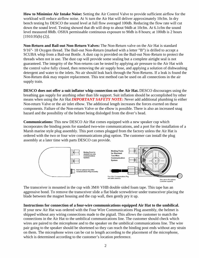
Communications: This new DESCO Air Hat comes equipped with a new speaker cup whichincorporates the binding posts for standard two-wire communications, and a port for the installation of aMarsh marine style plug assembly. This port comes plugged from the factory unless the Air Hat isordered with the two or four wire communications plug option. The customer can install the plugassembly at a later time with parts DESCO can provide.
The transceiver is mounted in the cup with 3M® VHB double sided foam tape. This tape has anaggressive bond. To remove the transceiver slide a flat blade screwdriver under transceiver placing theblade between the magnet housing and the cup wall, then gently pry it up.
Instructions for connection of a four-wire communications equipped Air Hat to the umbilical.If your new Air Hat was ordered with the Four Wire Communications Plug assembly, the helmet isshipped without any wiring connections made to the pigtail. This allows the customer to match theconnections in the Air Hat to the umbilical communications line. The customer should check whichwires are paired to the microphone and to the speaker on the umbilical communications line. The wirepair going to the speaker should be shortened so they can reach the binding post ends without any strainon them. The microphone wires can be cut to length according to the placement of the microphone,which is determined according to the customer’s location preference.
2
Installing a Four-wire communications assembly retrofit: Remove the port plug and clean andinspect the threads. Mix a small amount of fast set two-part epoxy, apply it to the threads on the fitting,and insert into the port. Tighten the fitting to approximately 3/4 of the length of the threads. Allow theepoxy to set per the manufacturers recommendations. Slip the compression nut and ferrules providedonto the plug pigtail. The nut and ferrules should be placed so as to leave enough of the plug out toconnect to the umbilical without straining. Approximate the final location of the plug in relation to thebulkhead fitting and strip off the excess cable sheathing, leaving enough to pass through the bulkheadfitting into the helmet. Insert the cable through the bulkhead fitting. If the cable resists passing throughapply soapy water or silicone spray to the cable. Also, the sheathing of the cable can be worked towardsthe bare wire ends of the cable to reduce the diameter to aid in installation. Tighten the compression nut.Follow the connection instructions above to complete the installation. Bench test the installation beforeplacing the Air Hat “in service”.
Light/Video Mounting Blocks: Two mounting blocks have been added to the snout of the Air Hat.They are supplied with a 3/8”-16 x ½” Brass hex bolt and a rubber washer. Mounting ancillary items onthe Air Hat will change the natural balance of the helmet and should be taken into account. The blocksare soft soldered to the helmet in recesses machined into the snout. This allows he block to break away ifsufficient force from being hit or hung up is applied. This feature offers some protection to the diver’shead and neck in a mishap involving the mounts.
Welding Shield: A Welding Shield accessory is available for the Air Hat from DESCO (Cat.No.61001W/S). It features a standard 4 ½”x 5 ¼” square lens, and the frame covers the entire faceplate.It comes with 2 stainless steel screws, which should be used in lieu of the brass window screws.
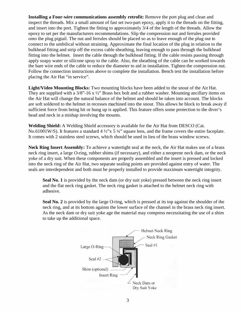
Neck Ring Insert Assembly: To achieve a watertight seal at the neck, the Air Hat makes use of a brassneck ring insert, a large O-ring, rubber shims (if necessary), and either a neoprene neck dam, or the neckyoke of a dry suit. When these components are properly assembled and the insert is pressed and lockedinto the neck ring of the Air Hat, two separate sealing points are provided against entry of water. Theseals are interdependent and both must be properly installed to provide maximum watertight integrity.
Seal No. 1 is provided by the neck dam (or dry suit yoke) pressed between the neck ring insertand the flat neck ring gasket. The neck ring gasket is attached to the helmet neck ring withadhesive.
Seal No. 2 is provided by the large O-ring, which is pressed at its top against the shoulder of theneck ring, and at its bottom against the lower surface of the channel in the brass neck ring insert.As the neck dam or dry suit yoke age the material may compress necessitating the use of a shimto take up the additional space.
3
These two seals are different both in operation and effect. The flat neck ring gasket used in Seal No.1 isan open-cell or sponge like material, which resists, but will not wholly prevent the passage of water. Anopen cell material is used since it maintains its shape under pressure at depth. So long as a positive airpressure is maintained in the Air Hat no water will enter. Should the pressure in the Air Hat becomenegative, as when the air is turned off and the diver inhales, a little water may enter. This can, however,readily be blown out through the neck dam simply by closing the exhaust valve so that air is forced outthrough the neck dam. Seal No.2, when installed properly provides a completely watertight seal. Theshim (optional) is provided to take up any space caused by the neck dam or yoke material compressingunder long term use.
Assembly of Neck Dam or Dry Suit Collar to Air Hat: To attach the DESCO neck dam to the Air Hathold the brass neck ring insert with its smaller diameter up. Bring the neck dam up through the ring wideend first. Fold the top edge of the neck dam out over the top of the insert ring so that the taped edge fitsinto the channel. Holding this point fold the rest of the top edge of the neck dam outward and over thechannel. The large O-ring is then placed in the insert ring channel on top of the neck dam material. Ifbecause of wear or compacting of this material the O-ring fits too loosely one or more rubber shims canbe placed in the channel on top or below the neck dam material, beneath the O-ring. When properlyfitted the O-ring should rest firmly against the neck dam material.
The collar of the Neoprene Breastplate or dry suit can be assembled to the neck ring insert in the samemanner except that with the thinner collar material it will nearly always be necessary to use one or morerubber shims in order to properly fit the O-ring. To insure a completely watertight seal care must betaken to see that the large O-ring is correctly fitted so its outer circumference contacts completelyaround the inside surface of the Air Hat neck ring when it is clamped in place.
Due to variances in materials and processes by suit manufacturers the fit of the drysuit yoke may requirethe use of shims.
The large O-ring in the Air Hat has been given a light coat of Silicone lubricant at the factory. It will befound that keeping the insert parts clean and lubricated will ease installing the neck ring insert assemblyinto the Air Hat, and will prolong the life of the O-ring. Use a lubricant suitable for rubber O-rings(petroleum free).
4
Section 2. Maintenance of the DESCO Air Hat
The DESCO Air Hat is simple to maintain and will provide reliable service with normal care andmaintenance. The following schedule will keep your DESCO Air Hat in top working order.
General Maintenance: The basic materials and construction of the DESCO Air Hat shell are the sameas those used in conventional diving gear like the U.S. Navy Mark V helmet, and it should generally becared for in the same manner. If used in salt water it should be washed off with fresh water after use, anddried with a clean cloth.
The Air Hat shell has a standard coating of tin-plating, or it can be painted as an option. If the finishbecomes badly worn the Air Hat can be disassembled and the shell can be retinned or repainted.
Painted Air Hats are coated with DuPont Imron Polyurethane Enamel Paint. This is a high durabilityAutomotive and Boat coating. This finish should be treated in the same manner as a cars finish.
The window is Acrylic and care should be taken to prevent scratching the surface. Clean the windowwith standard glass cleaner and a soft clean cloth. To remove very fine scratches and some stains use aspecially formulated plastic cleaner like Novus Plastic Polish No.2. This polish will also work on fineabrasions in the paint on the shell.
IMPORTANT MAINTENANCE NOTE: The flat neck ring gasket can be permanently compressed,which will reduce its effectiveness as a seal, if the neck ring insert assembly is left clamped in the AirHat while it is not in use. When the Air Hat is not going to be used for some time the neck ring insertassembly should be separated from the Air Hat.
Before each dive:1. Inspect all seals for nicks and tears. Replace as necessary.
2. Inspect the window for nicks, cracks, and deep scratches, which may weaken it. Pay specialattention to the screw holes.
3. Check the window screws for damage and tightness.
4. Check the air control valve for smooth operation. There should be some resistance to openingand closing of the valve to prevent accidental readjustment during the dive.
5. Inspect the clamp and lock mechanism for damage and adjustment. . There should be someresistance to opening and closing of the clamps and locks to prevent accidental opening duringthe dive.
6. Inspect the shell of the helmet for damage. Pay special attention to fittings and joints
7. Inspect the insert ring for damage. Also inspect the O-Ring, shim (if installed), and neck dam (ifinstalled).
8. Test the air train. With air connected check the operation of the non-return valves and air train.Close the air control valve to pressurize the air train. Turn off the compressed air supply to thehelmet. After one minute open the air control valve. Air should be heard escaping from the airdistributor. If no air is heard check all fittings for leakage, repair and retest.
5
Periodic Maintenance:Due to the varying conditions that DESCO Air Hats will encounter it is not possible to suggest afixed interval for periodic maintenance. The compressor, umbilical, environment, and usage will alleffect how often the Air Hat will need comprehensive maintenance. Particular attention should bepaid to these items when doing periodic maintenance. DESCO recommends that the periodicmaintenance be done fairly often. It is not possible to over maintain a DESCO Air Hat.
1. Check Lambswool in the Air Diffuser for discoloration and/or particulate matter. Replace if anycontamination is observed. ONLY USE Lambswool in the Air Diffuser. Use of any othermaterial in the Air Diffuser is not recommended.
2. Check the threading on the non-return valves for wear, dirt, or damage. Never use Teflon Tapein any part of the air train. Loose pieces of tape can clog the Lambswool or air controlvalve and result in loss of airflow.
3. Check all items, which are not easily accessible during the pre dive inspections.
To Replace the Flat Neck Ring Gasket: This gasket, as supplied with the Air Hat, is attached to theneck ring using Feathering Disc adhesive (used for attaching sanding disk paper sanders). This adhesiveallows for easier changing of the neck ring gasket. The gasket can be removed by peeling it gently offthe neck ring surface. A new gasket is installed using the same type of adhesive. Care should be taken tosee that the gasket’s outer edge is in contact with and adhered to the wall of the neck ring at all points,otherwise the gaskets effectiveness as a seal is reduced. Lacquer Thinner can be used on the tinned AirHats to remove adhesive residue when changing the neck ring gasket. Lacquer Thinner should not beused on painted helmets. Instead a cleaner like Goo Gone can be used as it will not damage the paint.
Repacking the Air Distributor with Lambswool: To pack the Air distributor with Lambswool take aquantity almost as large as a golf ball. Shred the Lambswool to loosen and fluff the fibers. Roll thefluffed Lambswool in your hands but do not compress it. The quantity you want will remain close to thesize of a golf ball. Use a flat screwdriver to tuck the ball of Lambswool into the Air Distributor. TheLambswool will be lightly packed once in place. Over packing the Air Distributor will reduce the airflow.
To Replace Pads on the Headband Assembly: The headpiece assembly is held in the Air Hat by asingle #10-32 hex nut in the center of the top band. To remove the headpiece assembly unscrew the hexnut as pull the headpiece assembly out by the side opposite the air control valve. On older helmets withthe diagonal binding post block backing out or removing the communications binding posts will easeremoval. The pads are attached with pressure sensitive tape making replacement simpler. The top pad isheld in place by a thin top pad above the band and a thick pad below the band. To change the padsremove the liner from the Air Hat. Peel off the old side pad and discard. Remove the old top pad bycutting it away. Clean any oil, grease, dirt, or old adhesive from the area where the new side pads will gowith Denatured Alcohol or Lacquer Thinner. Line up the new upper top pad with the mounting hole thenalign the lower top pad with the upper and press them together so the self adhesive tape forms a fullbond. Peel the paper backing from the new side pad and press firmly into place. Slide the headpieceassembly back into place. Watch the side pads as you install the liner so they do not roll as you press theliner into place. Check the liner to make sure it is centered in the Air Hat and replace and tighten the hexnut. Make sure all the solvents are completely gone before using the Air Hat again.
6
Section 3. Helmet Disassembly
1. Before doing any disassembly inspect the general condition of the helmet. Look for signs of wear,corrosion and/or damage.
a. Dents, deep scratches, or gouges in the helmet shellb. Scratches, chips, or hazing in the Acrylic window.c. Mechanical operation of the air control valve, exhaust valve, clamps and locks.d. Dents, nicks, or gouges in the insert ring.e. Holes in the neck dam (if installed).f. Cuts or gouges in the insert ring O-ring.g. Corrosion on any exposed solder joints.h. Corrosion to nuts, bolts, and screws.
2. Disassemble the helmet keeping the parts grouped together as they are removed. During the detailedinspection having the related parts together will aid in diagnosing problems. Some parts are bestexamined as they are removed from the helmet. Sub assemblies will be individually examined after thehelmet is disassembled. The disassembly sequence is as follows:
Insert Ring Assembly (with Neckdam installed):a. Remove the assembly from the helmet.b. Remove the O-ring from the insert ring.c. Remove the Neckdam from the insert ring.d. If the insert ring is fitted with a shim, remove it. On helmets where the shim has been in use
for a long time it may have adhered to the insert ring. It will be necessary to destroy the shimto remove it. Carefully scrape the shim off of the insert ring. The insert ring can be cleanedwith Lacquer thinner and very fine steel wool to remove the residual shim material.
Window Assemblya. Remove the six window screws from the front window. Take note of the force required to
remove them. The need for excessive force may indicate a damaged screw or significantcorrosion in the threads. Corrosion will be visually obvious on the screw threads. Check forany bent screws.
b. Remove the window and gasket from the helmet. The gasket may stick to the helmet frame,or the window, or both. If necessary you may use a thin blade screwdriver or putty knife torelease the gasket being careful not to damage any of the parts.
Exhaust Valve Assembly (Double Exhaust):a. Remove the two 6-32 screws closest to the helmet and pull the exhaust valve off of the base.b. Remove the O-ring and flapper valve.c. Remove the flapper screw and nut.
Exhaust Valve Assembly (Single Exhaust):a. Remove the four 6-32 screws in the cover assembly.b. Remove the flapper valve.c. Remove the flapper screw and nut.Clamp and Lock Assemblies:a. Unbolt each clamp and lock assembly keeping the related parts together.
7
Binding Posts and Communications:Old Style Installation:a. Remove the speaker by first unscrewing the lock screw from the speaker ring. Pull the speaker
and cup from the ring. Detach the wires from the binding posts. Remove the post retainingnuts and unscrew the binding posts. Remove the bushings from the block.
New Style Installation:a.Remove the speaker from the side cup. It is held in place with two sided foam tape. Using a flat
screwdriver gently pry up on the speaker, alternating sides until the tape releases. Detach thewires from the binding posts. Remove the post retaining nuts and pull out the binding posts.Remove the bushings from the cup.
Headpiece Assembly:a. Remove retaining nut in the center top of the helmet.b. On older helmets the side and top pads may be adhered to the shell. Slide a screwdriver or
putty knife along the shell and gently pry the pads loose. You may have to pry in severallocations to keep from tearing the pads.
c. On older helmets with the diagonal binding post block the liner is easiest to remove by pullingthe side by the binding post block in and up to clear the block then hooking the assemblyaround from under the air train assembly.
d. To replace the headpiece assembly insert the side at the air control valve first making sure it isclear of the copper tube. Rock the assembly in till the top band is over the retaining stud, thencheck the assembly is aligned left and right by gauging the distance between the snout/shellseam and the front end of the side pads. Replace and tighten the hex nut.
Air Train Assembly:a. Remove the Non-Return Valve/s from the helmet.b. Remove the Air Control Valve Handle.c. Loosen the valve-retaining nut.d. Loosen the compression nuts on the copper tube and remove the tube.e. Remove the valve-retaining stem adapter, valve retaining nut, brass and lead washers, and then
the valve. Use caution when removing the valve so as not to lose the compression ring off ofthe valve stem. A piece of tape on the valve stem before the valve is removed will preventloss.
f. Unscrew the Air Diffuser from the valve body.g. The inside elbow can be removed if needed. It is secured using 10-minute two-part epoxy. Use
two adjustable wrenches, one on the flats of the elbow and one to turn the first wrench. Useextreme caution to avoid damaging the threads or bending the elbow.
To remove the copper air distribution tube, first loosen the air control valve-retaining nut so that thevalve will rotate freely. Secondly, completely unscrew the compression nuts at both ends of the coppertube and rotate the valve body counter clockwise until the tube drops free. If the tube is undamaged itcan be reused. If replacement is necessary the compression ferrules will also have to be replaced. A setof stainless steel ferrules are used on the valve end, and a set of brass ferrules on the elbow end. Thesmall ferrule goes on first, then the larger one with the tapers on both pointing towards the end of thetube
Light/Video Block Assembly:a. Unscrew the two 3/8” bolts and Rubber washers from their blocks.
8
Section 4. Inspection of Air Hat Parts
Insert Ring O-ring: Wash the O-ring in soap and warm water to remove all dirt and contaminates. Do acareful inspection for cuts, nicks, or gouges. Look closely at the glue seam for any evidence of potentialfailure.
Neckdam: When examining for holes pay particular attention to the area where the Neckdam wrapsback around to pass under the O-ring. Slightly stretching the material aids in locating holes. Check forwear and stretching at the lower end of the Neckdam where it contacts with the diver’s neck.
Shim: Where the shim has been removed intact from the insert ring check for deterioration of the shimmaterial.
Insert Ring: Carefully inspect the insert ring for dents and nicks. Remove any burrs with very finesandpaper. Check the ring for evidence of damage, which may have put it out of round.
Window: Check the window carefully for cracks, scratches, or chips along the edges. Inspect thewindows gasket-sealing surface for dirt or gasket material adhering to it.
Window Gasket: Wash the gasket and window with soap and warm water. Carefully inspect the gasketfor cuts, cracking, or nicks, and check that the gasket is not gotten hard or soft.
Window Screws: Check for excessive corrosion or if the screw is bent. Look for cracking where thethreads meet the head.
Double Exhaust Valve: Generally look over the unit for contamination or damage. Inspect the solderjoint where the adjuster cap meets the top section. Look for corrosion or cracking. Check the movementof the plunger in the top section assembly and the action of the spring. Inspect the threads on the topsection adjuster assembly. Work the adjuster cap as a check for the condition of the cap threads.Excessive play in the operation of the adjuster would warrant further disassembly down to thecomponent parts. Check the condition of the plunger in the top section and the flapper guard in the midsection. Look for signs that the flapper valve(s) may be sticking to them.
Exhaust Valve O-ring: Wash the O-ring on soap and warm water. Carefully inspect for cuts and nicks.
Exhaust Valve Flapper Disk(s): Check for wear and cracking in the material. Look for signs ofphysical deterioration of the material such as hardening or softening. Look for signs that the flappervalve may be sticking to the plunger or flapper guard.
Exhaust Valve Body Sections: Look for signs of damage or corrosion. Look for plating flaking orcracking. Check the flapper valve sealing surface on the mid body for wear or damage. Check thethreads in the mid body for dirt or corrosion.
Single Exhaust Valve: Generally look over the unit for contamination, corrosion, cracking, or damage.Inspect the solder joint where the adjuster cap meets the cover. Check the movement of the plunger inthe cover assembly and the action of the spring. Work the adjuster cap as a check for the condition of thecap threads. Excessive play in the operation of the adjuster would warrant further disassembly down tothe component parts. Check the condition of the four cover retaining screws.
9
Clamps: Inspect the clamps for corrosion, bends and cracks. Inspect the clamp holes for cracks andwear.
Locks: Inspect the locks for cracks at the solder joint. Look for bending or twisting in the tab. Check thehole for cracking or wear.
Bolts & Nuts: Inspect the bolts for corrosion, wear, and bending. Look at the nuts for rounding off andthread corrosion or wear. Try threading the nuts and bolts together to test the threads and the nylon lockson the nuts. If the nuts will not self-lock they should be replaced. If the nylon washers appear to beflattened out replace them.
Binding Posts: Check the solder joint for cracking. Test the clamp nut for operation. Check for bending.Older binding posts were drilled for inserting the communications wire. If the binding post has this holelook for cracking of the post next to the hole. Check the bushing for cracks of excessive compression.Check for rounding off and the general condition of the threads.
Speaker: Check the speaker for operation using a sound source. Inspect the speaker, wire and terminalsfor wear, corrosion, or damage.
Speaker Cup: Check for wear and damage.
Headpiece Band Assembly: Inspect for corrosion, missing parts, or loose hardware. Check for wearand cracking.
Insert: Check for wear and excessive hardening of the pads. Check the screw fasteners to make surethey are still firmly attached to the pad.
Top & Side Pads: Inspect for wear, compression, or damage. Check that they are still firmly attached tothe band.
Non-Return Valve(s): Inspect the body parts for corrosion, wear, or damage. Check the threads forcondition. Check for damage to the valve seat. Look for loose plating or corrosion. Check the spring forloss of strength or corrosion.
Inside Elbow: Inspect the elbow for corrosion, wear, or damage.
Tube Inspect for corrosion, wear, or damage. Look for corrosion at the tube ends and on the ferruleswhere it can interfere with the seals.
Air Control Valve Inspect for corrosion, wear, or damage. Look inside the valve openings for signs offoreign material or contaminates. If the valve operation seemed loose before disassembly check thevalve packing. Check the valve stem for bending.
Air Distributor Inspect for contamination or damage. Carefully remove and place the Lambswool intoa plastic bag. Inspect the Lambswool for contaminates and foreign material. Check the opening in thebody for excessive wear. Look at the body for oil or contaminate saturation.
10
11
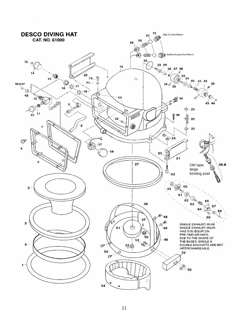
DESCO Air Hat Cat. No. 61000Exploded View & Parts List
1-3 NECK RING INSERT ASSEMBLY 610501. NECK SEAL O-RING 610542. NECK RING INSERT 610513. NECK DAM 610524. SHIM 610535-7 WINDOW ASSEMBLY 610755. WINDOW 610766. WINDOW RETAINING SCREWS 610787. WINDOW GASKET 610778-18 AIR INTAKE ASSEMBLY 611258. COPPER TUBE 611279. INSIDE ELBOW 6112610 AIR DISTRIBUTOR 6113511. LAMBSWOOL12. CONTROL VALVE 6112813. VALVE HANDLE NUT 6113414. VALVE HANDLE (SMALL) 61133S15. VALVE STEM ADAPTER 6113216. VALVE RETAINING NUT 6113117. BRASS WASHER 6113018. LEAD WASHER 6112919-27 POT & NECK RING ASSEMBLY 6102519. POT & NECKRING 6102620. NECK RING CLAMP (RIGHT) 6103421. NECK RING CLAMP (LEFT) 6103522. CLAMP SCREW 6103023. CLAMP & LOCK WASHER 6103124. CLAMP & LOCK NUT 6103225. LOCK 6103826. LOCK RETAINING SCREW 6103727. NECK RING GASKET 6103628-31 NON-RETURN VALVE ASS’Y 5909128. BODY 5307929. SPRING 5702930. PLATE 5203031. ADAPTER 5302931. ADAPTER (BAILOUT) 53029B32-44 DOUBLE EXHAUST ASSEMBLY 6023132. LOCKNUT 5302533. SCREW 5303734. FLAPPER 5602635. O-RING 6023436. FLAPPER GUARD 6023837. STAR WASHER 6023738. SET SCREW 6-32 6023539. CENTER SECTION 6023340. PLUNGER 5302441. SPRING 5702942. TOP SECTION 6023643. KNURLED CAP 5302844. NUT 54016
45-55 HEAD PIECE ASSEMBLY 6110045. TOP BAND 6110346. HEAD BAND 6110147. BACK PLATE 6110448. 3/8” BRASS SCREW 6110849. BRASS FLAT WASHER 6110950. BRASS NUT 6111051. TOP PAD 6111352. SIDE PAD 6111253. 7/16” BRASS SCREW 6111454. INSERT 6110655. SCREW 6110756-59 COMMUNICATIONS 6120056. BINDING POST ASS’Y (SMALL) 6122456A. BINDING POST ASS’Y (LARGE) 6120357. SPEAKER WITH CLIPS 6120558. FOAM SPEAKER COVER 6122659. ¼” NPT PIPE PLUG 6122760-68 SINGLE EXHAUST ASSEMBLY 59112T60. EXHAUST BASE 5102561. SCREW 5303762. FLAPPER 5302663. PLUNGER 5302464. SPRING 2700965. COVER 5209066. SCREW 5402567. CAP 5302868. NUT 5405869-71 VIDEO/LIGHT MOUNTS 6111569. VIDEO/LIGHT BLOCK 6111570. VIDEO/LIGHT BLOCK BOLT 6111671. VIDEO/LIGHT BLOCK WASHER 61117
NOT SHOWN ON EXPLODED VIEWThese parts are for older DESCO Air Hats. The transceiverwas mounted above the exhaust port in a plastic cup held bya brass ring. Two sizes of speaker were offered but thelarger may not fit on very old Air Hats due to the speakerring location. Parts with * indicate parts for the four wireretrofit offered for older Air Hats.
COMMUNICATIONSRETAINING SCREW 54009
57X SPEAKER WITH CLIPS 61204TELEPHONE CUP 61209*4 WIRE COMM ELBOW 61214*BULKHEAD FITTING 61215*4 WIRE PIGTAIL 61216
MISCELLANEOUS14X VALVE HANDLE (CAST) 6113314X VALVE HANDLE (LARGE) 61133N
12
SUB-ASSEMBLIESInstallations & Servicing
Section1. Installing the Air Train2. Assembling the Non-Return Valve3. Assembling the Double Exhaust Valve4. Servicing the Air Control Valve5. Spring Loaded Lock Conversion Instructions
DESCO Air Hat Air Train Installation Instructions
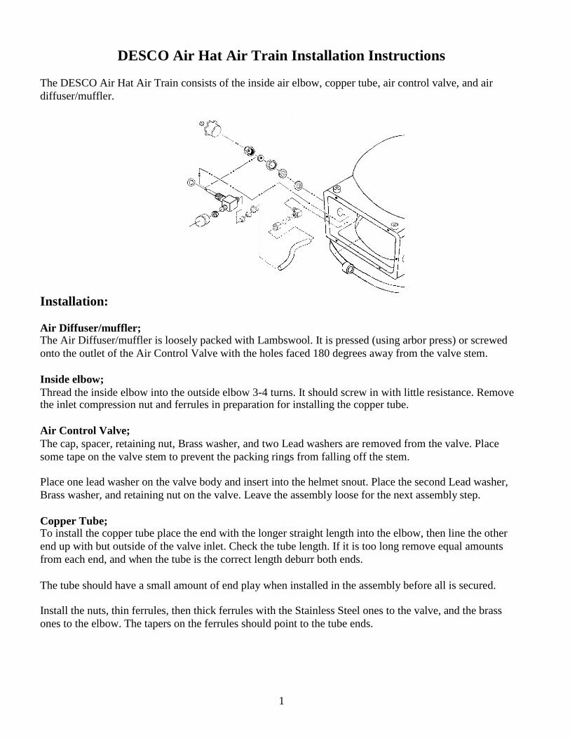
The DESCO Air Hat Air Train consists of the inside air elbow, copper tube, air control valve, and airdiffuser/muffler.
Installation:
Air Diffuser/muffler;The Air Diffuser/muffler is loosely packed with Lambswool. It is pressed (using arbor press) or screwedonto the outlet of the Air Control Valve with the holes faced 180 degrees away from the valve stem.
Inside elbow;Thread the inside elbow into the outside elbow 3-4 turns. It should screw in with little resistance. Removethe inlet compression nut and ferrules in preparation for installing the copper tube.
Air Control Valve;The cap, spacer, retaining nut, Brass washer, and two Lead washers are removed from the valve. Placesome tape on the valve stem to prevent the packing rings from falling off the stem.
Place one lead washer on the valve body and insert into the helmet snout. Place the second Lead washer,Brass washer, and retaining nut on the valve. Leave the assembly loose for the next assembly step.
Copper Tube;To install the copper tube place the end with the longer straight length into the elbow, then line the otherend up with but outside of the valve inlet. Check the tube length. If it is too long remove equal amountsfrom each end, and when the tube is the correct length deburr both ends.
The tube should have a small amount of end play when installed in the assembly before all is secured.
Install the nuts, thin ferrules, then thick ferrules with the Stainless Steel ones to the valve, and the brassones to the elbow. The tapers on the ferrules should point to the tube ends.
1
DESCO Air Hat Air Train Installation Instructions continued.
Final Assembly;Remove the copper tube and inside elbow. Using two part epoxy cement the inside elbow into the helmet.The epoxy should be the 10 – 15 minute type to allow time for reassembly. Make sure no epoxy covers theend of the valve or the opening in the helmet. A method of assuring there is no epoxy blocking the openingis to blow compressed air into the double elbow from the outside before the copper tube is reinstalled.Reinstall the copper tube and hand tighten all joints. If the copper tube is in contact with the helmet shellplace a piece of cardboard box under the tube as a spacer. Allow the epoxy to completely set.
Remove the cardboard spacer from under the copper tube (if used).
Tighten all connections starting with the air control valve retaining nut. The copper tube and inside elbowcan force the air control valve to cock if tightened first. It is important to align the air control valve with thesnout to insure the valve handle will not hit the snout.
Install the spacer and cap on the Air Control Valve stem.
After the Non-Return Valves are installed on the outside elbow the assembly can be pressure tested byattaching a 100psi air source to the helmet. With the ACV closed use dish soap and water solution to checkeach joint for leakage.
2
ASSEMBLY of the DESCO Non-Return Valve
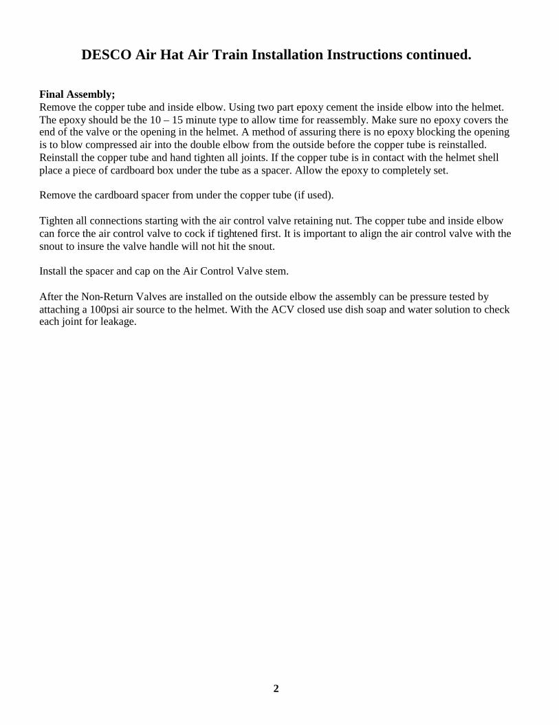
The Non-Return Valve on the DESCO Air Hat is the same part as is used on the DESCO Jack BrowneMask. This unit has been in use in excess of 50 years and has proven to be reliable.
Assembly of the Non-Return Valve is straight forward. It consists of four parts, the body, disk, spring, andadapter. There are twoversions of the adapter. The supply Non-Return Valve has a adapter which will accept a 9/16-18 Oxygenfitting for the supply umbilical hose. A second adapter for a Bailout whip has its inlet drilled to accept aSCUBA whip. It is stamped with a “B”.
All parts should be clean and free of defects.
To install the Non-Return Disk bend one tab out slightly to allow the spring to seat against the bottom ofthe disk. Bend the tab back to its original position.
Insert the disk and spring into the body.
Apply pipe thread compound to the threads on the body and assemble the parts.
Test the Non-Return Valve for leaks.
DESCO Air Hat Double Exhaust Assembly Instructions
The DESCO Air Hat Double Exhaust Valve consists of two flapper chambers. The upper flapper resistanceis adjustable, while the lower flapper resistance is fixed. Tension on the upper flapper is controlled by aknurled cap on the top of the exhaust valve which alters spring tension on the plunger.
Assembly:Top section;Screw the cap onto the exhaust cover completely. Check for roughness or catching in the threads whenscrewing the cap on. Unscrew the cap from the top section and clean the threads of any plating which mayhave flaked off.
Thread the cap onto the top section ¼ turn. Place the spring over the plunger and insert the plunger into thetop section and cap assembly so the threaded stud protrudes from the cap. Install the hex nut on thethreaded stud to hand tight. Back the cap slightly to wedge the nut in position.
Remove the excess threaded stud above the hex nut. Using a center punch put three dimples in the end ofthe stud to prevent the hex nut from coming off. Make sure the relief hole in the center of the stud is open.The relief hole prevents a vacuum from forming between the flapper and plunger.
Screw the cap down fully to make sure the spring will not catch between the top section and the cap. If thecap does not screw down fully the spring is shifted to one side and is pinching between the cap and topsection. Run the cap up and lightly tap the side of the top section on a table or bench top to reposition thespring.
Center Section;Screw the 10-32 Pan Head screw into the center section about 1/3 of the way in.
Place the flapper disk onto the screw head. Turn the flapper disk down until it sits evenly on the centersection. Turn it flapper disk in an additional 1/8 turn to put tension on it.
Turn the assembly over and install the star lock washer and flapper guard. Tighten the flapper guard usingneedle nose pliers in the relief holes.
The top and center sections can now be assembled using two 6-32 Stainless Steel Pan Head screws.
1
DESCO Air Hat Double Exhaust Assembly Instructions continued.
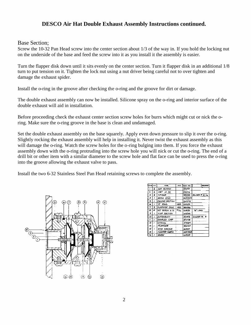
Base Section;Screw the 10-32 Pan Head screw into the center section about 1/3 of the way in. If you hold the locking nuton the underside of the base and feed the screw into it as you install it the assembly is easier.
Turn the flapper disk down until it sits evenly on the center section. Turn it flapper disk in an additional 1/8turn to put tension on it. Tighten the lock nut using a nut driver being careful not to over tighten anddamage the exhaust spider.
Install the o-ring in the groove after checking the o-ring and the groove for dirt or damage.
The double exhaust assembly can now be installed. Silicone spray on the o-ring and interior surface of thedouble exhaust will aid in installation.
Before proceeding check the exhaust center section screw holes for burrs which might cut or nick the o-ring. Make sure the o-ring groove in the base is clean and undamaged.
Set the double exhaust assembly on the base squarely. Apply even down pressure to slip it over the o-ring.Slightly rocking the exhaust assembly will help in installing it. Never twist the exhaust assembly as thiswill damage the o-ring. Watch the screw holes for the o-ring bulging into them. If you force the exhaustassembly down with the o-ring protruding into the screw hole you will nick or cut the o-ring. The end of adrill bit or other item with a similar diameter to the screw hole and flat face can be used to press the o-ringinto the groove allowing the exhaust valve to pass.
Install the two 6-32 Stainless Steel Pan Head retaining screws to complete the assembly.
2
Servicing the Air Control Valve
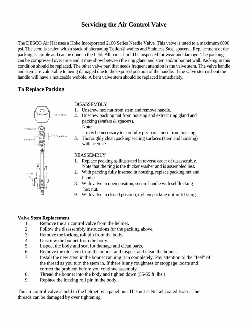
The DESCO Air Hat uses a Hoke Incorporated 2100 Series Needle Valve. This valve is rated to a maximum 6000psi. The stem is sealed with a stack of alternating Teflon® wafers and Stainless Steel spacers. Replacement of thepacking is simple and can be done in the field. All parts should be inspected for wear and damage. The packingcan be compressed over time and it may show between the ring gland and stem and/or bonnet wall. Packing in thiscondition should be replaced. The other valve part that needs frequent attention is the valve stem. The valve handleand stem are vulnerable to being damaged due to the exposed position of the handle. If the valve stem is bent thehandle will have a noticeable wobble. A bent valve stem should be replaced immediately.
To Replace Packing
DISASSEMBLY1. Unscrew hex nut from stem and remove handle.2. Unscrew packing nut from housing and extract ring gland and
packing (wafers & spacers).Note:It may be necessary to carefully pry parts loose from housing.
3. Thoroughly clean packing sealing surfaces (stem and housing)with acetone.
REASSEMBLY1. Replace packing as illustrated in reverse order of disassembly.
Note that the ring is the thicker washer and is assembled last.2. With packing fully inserted in housing, replace packing nut and
handle.8. With valve in open position, secure handle with self locking
hex nut.9. With valve in closed position, tighten packing nut until snug.
Valve Stem Replacement1. Remove the air control valve from the helmet.2. Follow the disassembly instructions for the packing above.3. Remove the locking roll pin from the body.4. Unscrew the bonnet from the body.5. Inspect the body and seat for damage and clean parts.6. Remove the old stem from the bonnet and inspect and clean the bonnet.7. Install the new stem in the bonnet running it in completely. Pay attention to the “feel” of
the thread as you turn the stem in. If there is any roughness or stoppage locate andcorrect the problem before you continue assembly.
8. Thread the bonnet into the body and tighten down (55-65 ft. lbs.)9. Replace the locking roll pin in the body.
The air control valve is held in the helmet by a panel nut. This nut is Nickel coated Brass. Thethreads can be damaged by over tightening.
Spring Loaded Lock Conversion Instructionsfor the DESCO Air Hat Cat. No. 61041
This conversion kit was developed for DESCO Air Hats which will be used in an environment wheresignificant snagging hazards exist.
The clamping system on a standard Air Hat relies upon drag being induced on the clamp and lock via thebolts, nuts, and Nylon washers. It is necessary in any pre-dive inspection to assure that sufficient drag ispresent on a standard Air Hat clamping system. Drag is set by tightening the self locking nuts on both theclamps and locks until they will stay in any position they are placed.
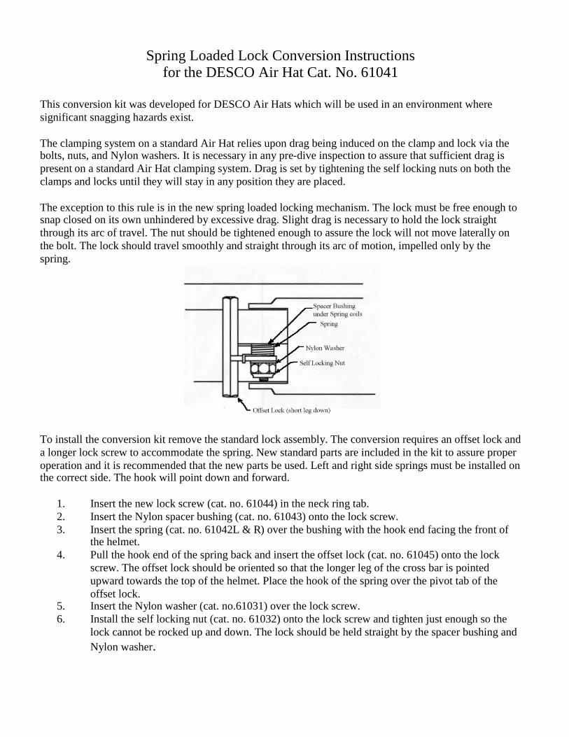
The exception to this rule is in the new spring loaded locking mechanism. The lock must be free enough tosnap closed on its own unhindered by excessive drag. Slight drag is necessary to hold the lock straightthrough its arc of travel. The nut should be tightened enough to assure the lock will not move laterally onthe bolt. The lock should travel smoothly and straight through its arc of motion, impelled only by thespring.
To install the conversion kit remove the standard lock assembly. The conversion requires an offset lock anda longer lock screw to accommodate the spring. New standard parts are included in the kit to assure properoperation and it is recommended that the new parts be used. Left and right side springs must be installed onthe correct side. The hook will point down and forward.
1. Insert the new lock screw (cat. no. 61044) in the neck ring tab.2. Insert the Nylon spacer bushing (cat. no. 61043) onto the lock screw.3. Insert the spring (cat. no. 61042L & R) over the bushing with the hook end facing the front of
the helmet.4. Pull the hook end of the spring back and insert the offset lock (cat. no. 61045) onto the lock
screw. The offset lock should be oriented so that the longer leg of the cross bar is pointedupward towards the top of the helmet. Place the hook of the spring over the pivot tab of theoffset lock.
5. Insert the Nylon washer (cat. no.61031) over the lock screw.6. Install the self locking nut (cat. no. 61032) onto the lock screw and tighten just enough so the
lock cannot be rocked up and down. The lock should be held straight by the spacer bushing andNylon washer.

TESTINGFlow testing the Air Hat
Leak testing the Non-Return Valve
Flow testing the DESCO Air Hat
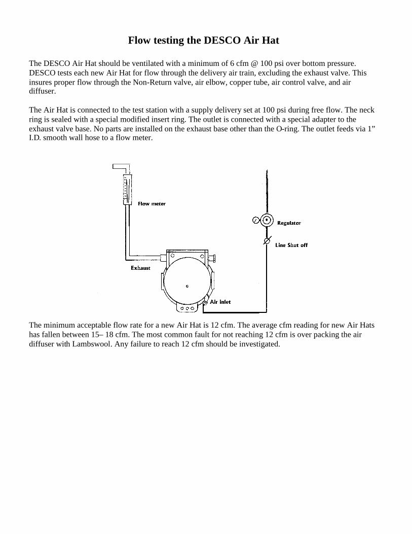
The DESCO Air Hat should be ventilated with a minimum of 6 cfm @ 100 psi over bottom pressure.DESCO tests each new Air Hat for flow through the delivery air train, excluding the exhaust valve. Thisinsures proper flow through the Non-Return valve, air elbow, copper tube, air control valve, and airdiffuser.
The Air Hat is connected to the test station with a supply delivery set at 100 psi during free flow. The neckring is sealed with a special modified insert ring. The outlet is connected with a special adapter to theexhaust valve base. No parts are installed on the exhaust base other than the O-ring. The outlet feeds via 1”I.D. smooth wall hose to a flow meter.
The minimum acceptable flow rate for a new Air Hat is 12 cfm. The average cfm reading for new Air Hatshas fallen between 15– 18 cfm. The most common fault for not reaching 12 cfm is over packing the airdiffuser with Lambswool. Any failure to reach 12 cfm should be investigated.
Leak testing of DESCO Non-Return Valve
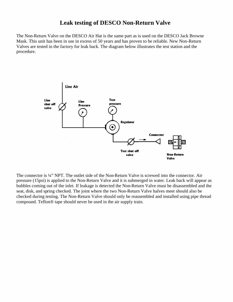
The Non-Return Valve on the DESCO Air Hat is the same part as is used on the DESCO Jack BrowneMask. This unit has been in use in excess of 50 years and has proven to be reliable. New Non-ReturnValves are tested in the factory for leak back. The diagram below illustrates the test station and theprocedure.
The connector is ¼” NPT. The outlet side of the Non-Return Valve is screwed into the connector. Airpressure (15psi) is applied to the Non-Return Valve and it is submerged in water. Leak back will appear asbubbles coming out of the inlet. If leakage is detected the Non-Return Valve must be disassembled and theseat, disk, and spring checked. The joint where the two Non-Return Valve halves meet should also bechecked during testing. The Non-Return Valve should only be reassembled and installed using pipe threadcompound. Teflon® tape should never be used in the air supply train.

Air Hat Inspection ReportUpon completion of inspection and repair of the Air Hat a report should be filled out todocument the services performed. This report should be kept on file as an ongoing record ofmaintenance of the helmet.
The sample report provided is nearly identical to the report supplied by DESCOCorporation when inspections are done at our facility. This report will satisfy current recordkeeping requirements of the government and trade associations.
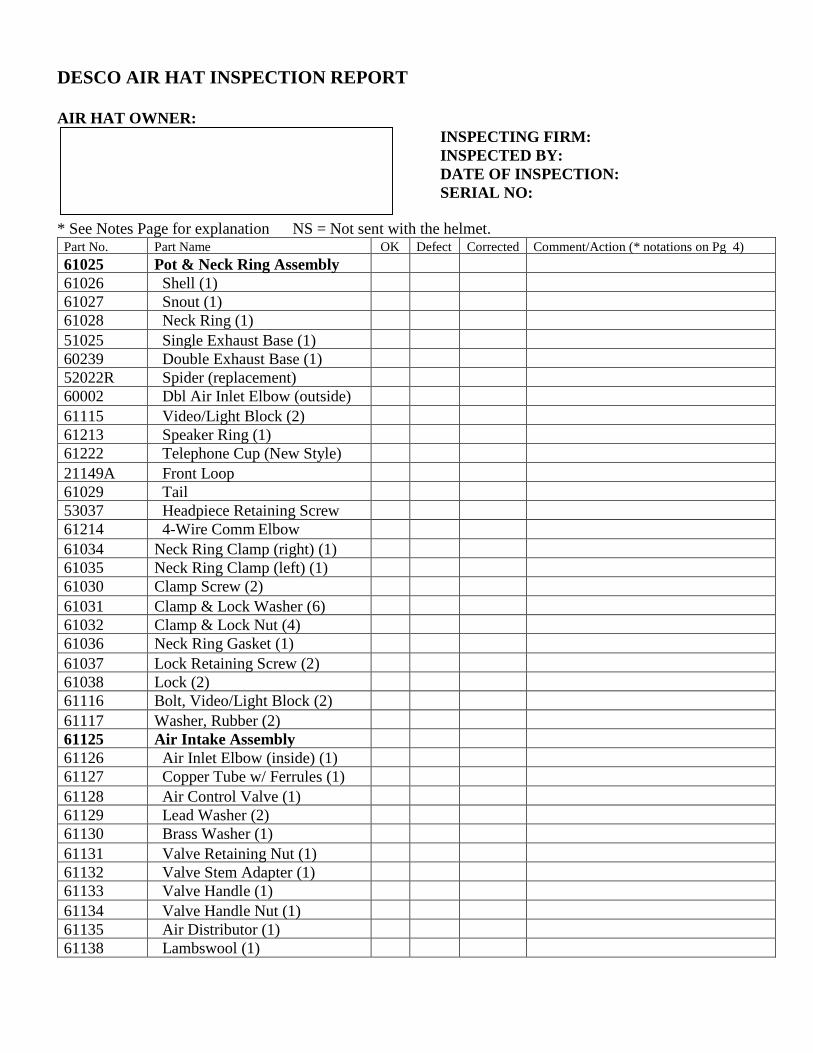
DESCO AIR HAT INSPECTION REPORT
AIR HAT OWNER:INSPECTING FIRM:INSPECTED BY:DATE OF INSPECTION:SERIAL NO:
* See Notes Page for explanation NS = Not sent with the helmet.Part No. Part Name OK Defect Corrected Comment/Action (* notations on Pg 4)61025 Pot & Neck Ring Assembly61026 Shell (1)61027 Snout (1)61028 Neck Ring (1)51025 Single Exhaust Base (1)60239 Double Exhaust Base (1)52022R Spider (replacement)60002 Dbl Air Inlet Elbow (outside)61115 Video/Light Block (2)61213 Speaker Ring (1)61222 Telephone Cup (New Style)21149A Front Loop61029 Tail53037 Headpiece Retaining Screw61214 4-Wire Comm Elbow61034 Neck Ring Clamp (right) (1)61035 Neck Ring Clamp (left) (1)61030 Clamp Screw (2)61031 Clamp & Lock Washer (6)61032 Clamp & Lock Nut (4)61036 Neck Ring Gasket (1)61037 Lock Retaining Screw (2)61038 Lock (2)61116 Bolt, Video/Light Block (2)61117 Washer, Rubber (2)61125 Air Intake Assembly61126 Air Inlet Elbow (inside) (1)61127 Copper Tube w/ Ferrules (1)61128 Air Control Valve (1)61129 Lead Washer (2)61130 Brass Washer (1)61131 Valve Retaining Nut (1)61132 Valve Stem Adapter (1)61133 Valve Handle (1)61134 Valve Handle Nut (1)61135 Air Distributor (1)61138 Lambswool (1)

DESCO Air Hat Inspection Report Page 2Date: Owner: Serial Number:* See Notes Page for explanation NS = Not sent with the helmet.
Part No. Part Name OK Defect Corrected Comment/Action (* notations on Pg 4)61075 Window Assembly61076 Window (1)61077 Window Gasket (1)61078 Window Retaining Screw (6)61100 Headpiece Assembly61101 Head Band (1)61103 Top Band (1)61104 Back Plate (2)61106 Insert (1)61107 Screw, SS (4)61108 Screw, 3/8” Brass (2)61109 Flat Washer (6)61110 Brass Nut (6)61112 Side Pad (2)61113 Top Pad (1)61114 Screw, 7/16” Brass (4)59091 Non-Return Valve Assembly52030 Plate (1)53029 Adapter (1)53079 Body (1)57029 Spring (1)59091B Bailout Non-Return Valve Ass’y52030 Plate (1)53029B Adapter (1)53079 Body (1)57029 Spring (1)61136 Dust Cap (1)60231 Double Exhaust Assembly53024 Plunger (1)53025 Lock Nut (1)53028 Knurled Cap (1)53037 Flapper Screw (2)54016 Nut (1)56026 Flapper Disc (2)57029 Spring (1)60233 Center Section (1)60234 O-Ring (1)60235 Set Screw (4)60236 Top Section (1)60237 Star Washer (1)60238 Flapper Guard (1)
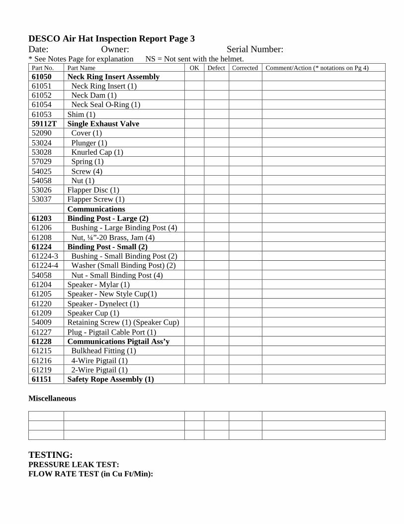
DESCO Air Hat Inspection Report Page 3Date: Owner: Serial Number:* See Notes Page for explanation NS = Not sent with the helmet.
Part No. Part Name OK Defect Corrected Comment/Action (* notations on Pg 4)61050 Neck Ring Insert Assembly61051 Neck Ring Insert (1)61052 Neck Dam (1)61054 Neck Seal O-Ring (1)61053 Shim (1)59112T Single Exhaust Valve52090 Cover (1)53024 Plunger (1)53028 Knurled Cap (1)57029 Spring (1)54025 Screw (4)54058 Nut (1)53026 Flapper Disc (1)53037 Flapper Screw (1)
Communications61203 Binding Post - Large (2)61206 Bushing - Large Binding Post (4)61208 Nut, ¼”-20 Brass, Jam (4)61224 Binding Post - Small (2)61224-3 Bushing - Small Binding Post (2)61224-4 Washer (Small Binding Post) (2)54058 Nut - Small Binding Post (4)61204 Speaker - Mylar (1)61205 Speaker - New Style Cup(1)61220 Speaker - Dynelect (1)61209 Speaker Cup (1)54009 Retaining Screw (1) (Speaker Cup)61227 Plug - Pigtail Cable Port (1)61228 Communications Pigtail Ass’y61215 Bulkhead Fitting (1)61216 4-Wire Pigtail (1)61219 2-Wire Pigtail (1)61151 Safety Rope Assembly (1)
Miscellaneous
TESTING:PRESSURE LEAK TEST:FLOW RATE TEST (in Cu Ft/Min):

DESCO Air Hat Inspection Report Page 4
Date: Owner: Serial Number:*Notes:
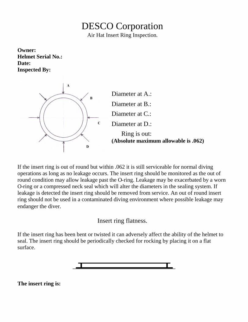
DESCO CorporationAir Hat Insert Ring Inspection.
Owner:Helmet Serial No.:Date:Inspected By:
Diameter at A.:
Diameter at B.:Diameter at C.:
Diameter at D.:Ring is out:
(Absolute maximum allowable is .062)
If the insert ring is out of round but within .062 it is still serviceable for normal divingoperations as long as no leakage occurs. The insert ring should be monitored as the out ofround condition may allow leakage past the O-ring. Leakage may be exacerbated by a wornO-ring or a compressed neck seal which will alter the diameters in the sealing system. Ifleakage is detected the insert ring should be removed from service. An out of round insertring should not be used in a contaminated diving environment where possible leakage mayendanger the diver.
Insert ring flatness.
If the insert ring has been bent or twisted it can adversely affect the ability of the helmet toseal. The insert ring should be periodically checked for rocking by placing it on a flatsurface.
The insert ring is: