Embed Size (px)
Citation preview

Deposition of diamond-like carbon coatings byunbalanced magnetron sputteringPrincen, E.P.H.
Published: 01/01/1994
Document VersionPublisher’s PDF, also known as Version of Record (includes final page, issue and volume numbers)
Please check the document version of this publication:
• A submitted manuscript is the author's version of the article upon submission and before peer-review. There can be important differencesbetween the submitted version and the official published version of record. People interested in the research are advised to contact theauthor for the final version of the publication, or visit the DOI to the publisher's website.• The final author version and the galley proof are versions of the publication after peer review.• The final published version features the final layout of the paper including the volume, issue and page numbers.
Link to publication
General rightsCopyright and moral rights for the publications made accessible in the public portal are retained by the authors and/or other copyright ownersand it is a condition of accessing publications that users recognise and abide by the legal requirements associated with these rights.
• Users may download and print one copy of any publication from the public portal for the purpose of private study or research. • You may not further distribute the material or use it for any profit-making activity or commercial gain • You may freely distribute the URL identifying the publication in the public portal ?
Take down policyIf you believe that this document breaches copyright please contact us providing details, and we will remove access to the work immediatelyand investigate your claim.
Download date: 02. Aug. 2018

TUE-investigationproject
Technical University of EindhovenMechanical EngineeringSection Manufacturing of materials
DEPOSITION OF DIAMOND-LIKE CARBONCOATINGS BY UNBALANCED MAGNETRONSPUTTERING.
Edo PrincenEindhoven, november 1994
Report nr. WPA: 110006
Tutors: Dr. D.G. TeerTeer Coatings Limited, 290 Hartlebury Trading Estate, WorcesterDYlO 4ffi (UK)
Dr. ir. J.H. DautzenbergTechnical University EindhovenDepartment Mechanical Engineering

ABSTRACT
Amorphous hydrogenated carbon films contammg a small amount of metal (Me-C:H)have been deposited by closed field unbalanced magnetron sputtering. The films havegraded compositions to optimise the adhesion to the substrates. Multilayer TiC/Ti-C:Hfilms have also been deposited. The films have excellent properties: high microhardness(more than 2000 Hv), excellent adhesion to tool steel (a critical load of 100 N in thescratchtest) and a coefficient of friction against bearingsteel of about 0.1. The coatingprocedure, for in generally metals, is ideally suited to the system used. The graded filmpreparation is important for the intrinsic stress. The rather low deposition temperature(about 200°C) has no influence on the properties of the metal substrate.

CONTENTS
CHAPTER 1 Introduction..................................................... p. 1
CHAPTER 2 Diamond-like carbon coatings (DLC)....................... p. 2
CHAPTER 3 Experimental details............................................ p. 4
CHAPTER 4 Analyses p. 5
CHAPTER 5 Results........................................................... p. 7
5.1 DLC without TiN interlayer. .
5.2 DLC with titanium and niobium targets .
5.3 DLC without the gradually TiC interlayer. .
5.4 DLC with or without nitrogen in the final stage .
5.5 DLC with rather thin TiN and TiCN interlayers .
5.6 DLC etching with argon ions ..
5.7 DLC on cemented carbide inserts .
CHAPTER 6 Discussion........................................................ p. 10
References p. 11
Appendix .
A -figures p. 12B -properties of diamond and DLC p. 16C -standard DLC procedure p. 17D -DLC composition on cemented carbids........... p. 19

1 INTRODUCTION
The deposition of amorphous hydrogenated carbon films (Me:C-H) have been performedin a multiple magnetron coating system by the magnetron sputter ion plating technique.The apparatus is named the uniform deposition and plasma (UDP) system, and exists of aclosed field unbalanced magnetron sputtering arrangement (PLASMAG).The basis of the technique is that the outer magnets of the magnetron are made relativelymuch stronger, compared with the central magnet, than with the conventional magnetron.This can be done by placing more permanent magnets on the perimeter of the magnetron,or by simply weakening the central magnet. The several magnetrons are used to surrounda central substrate, and adjacent magnetrons are manufactured with opposite polarities.The plasma is then confined within this closed field, preventing loss of electrons to thechamber walls and creating intense ion bombardment of the substrate.
The hybrid CVD/PVD process is controlled by a simple technique based on opticalemission spectroscopy. An optical emission monitor is combined with a photomultiplier tomonitor the intensity of the metal plasma in the neighbourhood of the target surface. Arapid response piezo-electric valve is then used to control the intensity of the plasma to agiven level by an inlet of the reactive gas. The intensity setting gives the requiredstoichiometric composition of the compound being deposited. The intensive titanium lineat 506 nm was selected as most suitable light emission of the plasma to control theprocess. [1]
The small amounts of metal in DLC have beneficial effects onto the compressive stress inthe coating. A-C:H gives a rather high compressive stress, reducing the adhesionespecially on steel. This is an essential reason for its limited practical application. Metalcontaining hydrocarbon have much lower compressive stress than a-C:H. However, thewear resistance and friction coefficients are rather similar. [2]
Me-C:H can be prepared by reactive RF sputtering[4] or by reactive DC magnetronsputtering[6] in an argon-hydrocarbon gas mixture using metal targets. DC magnetronsputtering is somewhat difficult for films with low metal contents. It needs rather highreactive gas concentrations. Above a critical flow the target tends to be completelypoisoned with a carbon film. The magnetron discharge becomes unstable.The deposition rate for DC is about one order of magnitude higher than RF magnetronsputtering and very promising with respect to industrial needs.
Edo Princen, November 1994 1
2 DIAMOND-LIKE CARBON COATINGS (DLC)
The DLC film composes of a mixture of diamond, graphite and polymeric crystalstructures. Diamond-like solids are often discussed together with crystalline diamondfilms even though their structure is significantly different (appendix B). The reason is thatthe diamond-like films exhibit a number of properties of bulk diamond. The diamond-likesolids have very high densities compared with other conventional hydrocarbons andhydrocarbon polymers[3]. This high number density arises from their completely crosslinked structure and is another point of similarity with crystalline diamond.
The structure exists of SP3 coordinated carbon, tetrahedrally bonded to four other atoms,SP2 carbon, trigonally bonded to three other atoms, and finally free bonds saturated byhydrogen atoms.Diamond and graphite are two crystalline allotropes of carbon. In the diamond crystalstructure each atom is covalently bonded to four other carbon atoms (SP3). Graphite ismade up of layers of carbon atoms with strong trigonal bonds (SP2) in the basal plane.The fourth electron in the outer shell forms a weak Van der Waals bond between theplanes, and accounts for such properties of graphite as lubricity, lower density, softnessand a greyish black appearance.In order to grow true diamond films, the SP3 type of tetrahedral carbon bonding must beexclusively maintained in a dynamic non-equilibrium system. It is now generally acceptedthat atomic hydrogen plays a crucial role in the promotion of SP3 bonding and for purediamond deposition atomic hydrogen must be present. When carbon deposits tetrahedrally, each carbon atom on the growing face has a "swinging" bond and it is believed thatthese bonds are stabilised by the presence of atomic hydrogen. Also, if the carbon istending to form a graphitic stucture, it can be broken up by energetic particle bombardment, since the SP2 bonds are energetically less stable. The bombarding species may behydrogen, oxygen, argon or any other ionised or energetic species.The following figure shows schematicly the structure.
,I
IGRAPHITIC
..,.....- DIAMOND-LIKE
Figure 2.1 Sketch of a representative compound model for amorphous hydrogenated carbon (a-C:H)
Edo Princen, November 1994 2

Depending on the deposition method and parameters, the films may contain up to 50%hydrogen[7]. As a result of this structure, such amorphous diamond-like carbon films aremore elastic than diamond.
Certain DLC films deposited by plasma-aided processes have extremely high internalcompressive stresses and are extremely sensitive to microstructural disturbances. Even theslightest damage to the films may lead to spalling of large areas of the film. This,combined with the structure mismatch when DLC is applied to different kind of substrates, commonly leads to poor adhesion. In high mechanical stress applications, theadhesion of the films is often the critical factor.Grading of very hard alloy nitride films through various intermediate compounds ofdifferent compositions has been shown to increase the scatch adhesions levels[I]. Theinterfaces ensure no abrupt changes in composition and the (compressive) stress isintroduced gradually.It has been found that the optimum film sequence in this case is:
Ti, TiN, TiCN, TiC, DLC.
It has also been subsequently found that the mechanical properties of the hard carbonfilms can be improved by incorporating a small percentage of metal dopant (usually :::::: 5%titanium)[1] .
On the other hand is compressive stress necessary for diamond-like structure (SP3)
formation in a hydrocarbon atmosphere[5]. The deposition mechanism is shown in thefollowing figure.
=C--C=I II I
H H
=C=C=
=C=C=
H-H t----- >
compression----- >
=C=C=
=C--C=I II I
=C--C=
(2.1)
(2.2)
Edo Princen, November 1994 3

3 EXPERIMENTAL DETAILS
The process used here for deposition of the carbon films (Me-C:H) is based upon atechnique first reported by Dimigen and co-workers[4]. The introduction of a hydrocarbon gas (acetylene, butane) during sputtering causes a breakdown of the gas on the puremetal target surface so that the metal and hydrocarbon are sputtered simultaneously fromthe poisoned target surface. The amount of target poisoning by the hydrocarbon willdetermine for more than 90% the final composition of the DLC film. The other 10%structure is contributed by a plasma polymerization component[3].If total poisoning of the metal target results, the process tends to become unstable owingto the non-conducting layer of carbon on the target surface, and "arcing" results.
A low RF power (13.56 Mhz) is often applied to the substrates to promote ion assistanceduring film deposition. In other words, the ion current density (ICD) to the substrates willbe higher with RF bias voltage.
It is also possible to deposit a-C in a non-reactive mode. The graphite targets are conducting and therefore DC can again be applied to the magnetrons. The sputtered carbon isthen deposited onto the workpieces with RF substrate bias without any hydrocarbon gaspresent.The presence of the hydrocarbon gas will usually increase the deposition rate, but mayaffect the other properties due to the hydrogen concentration (see chapter 2 I).
Appendix C shows Teer's standard DLC procedure.The 'standard' DLC in production has the following configuration, minding different kindof DLC can be prepared. The coating looks the same, but many parameters can bechanged (different bias voltage, deposition times, gases, other apparatus etc.)
DLC
TiC
TiCN
TiN
Tis u bs1:ra.1:e
Fig. 3.1 A possible DLC coating for a substrate
Edo Princen, November 1994 4

4 ANALYSES
The several coatings were investigated by wear/friction test, ball cratering, scratch test,hardness-test and S.E.M.
The wear/friction test ("ball on disc test") is particularly valuable for the tribologicalbehaviour. However, it is a first evaluation of a coating and in practice approval is stillthe one and only ultimate test.Important factors with respect to the used wear-tester:
* air humidity plays an important role. Especially in the case of DLC. The reaction layerdependant on the environment determines the coefficient of friction and the wear rate.The relationship is often more or less like; low friction, high wear rate coatings in a dryenvironment and vice versa in a humid environment.DLC forms a reaction layer in a tribological system under humid air conditions. Thislayer decreases the wear rate, but increases the coefficient of friction. It is in this case notanymore a pure graphitic friction like the dry air condition case. In the latter case is noformation of a reaction layer. This results in a lower coefficient of friction, but a higherwear rate of particularly the graphitic structure. Both coating-properties are of course alsodependant on the share of diamond-like and polymeric structure. As a rule of thumb itcan be concluded that the diamond-like structure is always beneficial for the coefficient offriction and the wear rate. This structure is non-reactive and very hard.
* the counterpart (=ball) is always bearing steel. Other materials could give oppositeresults.
* the contact area is circular, which is very unlikely in practice.
* the normal force is in the same direction as the gravity force. This introduces anunpleasant effect in the case of hard coatings. Abrasive particles could get stuck in thecontact area. High wear rates are then very common, while another normal forcedirection shows less wear.
* the ratio of adhesive, ploughing or chemical wear is difficult to measure. This problemmight be solved assuming the ploughing effect of friction will be present in the firstrounds.
Ball cratering is a fast method to define the different layer thickness. In this experimentthe coating is polished locally. A crater is made by rolling a ball, for several minutes, ina diamond paste on the same place. This method is for determining the layer thicknesseven better than the available S.E.M., because it is possible to distinct the different layersby colour.
Scratch testing (scratchtester ST 200) is a method to determine one of the most importantfactors of mechanical coatings, the adhesion strength to the substrate. Better known as thecritical load.
Edo Princen, November 1994 5

Optical investigation of not just the total failure load but also the area around the scratchgives even more information e.g. interface bonding, internal stress, failure mode (ductileor brittle) etc. Referring to the literature of BuU[9].
The hardness test (300 gr. Vickers) is mainly to check the brittleness of the coatinge.The absolute value has no sense, because the influence of the substrate is too big at a loadof 300gr. and DLC is elastic!
The S.E.M. is a good mean to examine for the structure (columnar, dense, adhesion)and to determine the individual layer thickness. Figure 4.1 shows a S.E.M. picture of aDLC coating. It is possible to distinct two layers, a light and a dark one. The light layerhas a columnar structure, the dark layer a dense structure.
Figure 4.1 S.E.M. picture of a DLe coating (6900 xl
Edo Princen, November 1994 6

5 RESULTS
The next combinations, compared to the 'standard DLC-procedure' (appendix C) havebeen investigated:
5.1 DLC without TiN interlayer
According to the publication of Ghosh and Kohler[8] the adhesion of TiCN on Ti is betterthan TiN on Ti (critical load resp. 60N and 50N).This apparent difference is tested in run numbers 8/22, 8/23 and 8/24 (runsheets at TeerCoatings Limited). The experimental results don't show any reasonable contrast betweenthe two different interlayer structures in DLC. An explanation can be found in the factthat all the interlayers are related to each other. In the published report TiN and TiCN aretoplayers. In DLC-coatings, TiN and TiCN are interlayers.The meaning of interlayers will be discussed further in this report.
5.2 DLC with niobium and titanium targets
Niobium is also a carbide-forming element. The difference between titanium, concerningsputtering, is the about 3/2 higher sputter rate in an argon atmosphere and the larger atomsize than titanium.The unstable, relative big NbC (room temperature) could introduce compressive stress,necessary for the tetrahedral Sp3 structure (chapter 2).
Samples of run 8/21 on toolsteel, produced with 1 Ti-target and 1 Nb target, showed verygood tribological properties in comparison with standard DLC.In run-numbers 1 to 5, 2 Ti-targets and 1 Nb-target were used. One of the optimisedcoatings has the next properties.COF against steel 0.1critical load total failure 45 N ; edge failure 15 NNo wear on counterpart after 1 hour 80 N wear-testingUnfortunately, there was a leak in the Argon-pipe. Oxygen was in the chamber and it iswell known that oxygen favours diamond growth.
The next remarks should be considered:1) The scratchtest showed a lot of flaking. Probably because of the leak,causing
contamination.
2) Wear and friction qualities are excellent, referring to the mentioned properties.This behaviour could be caused by a high SP3/SP2 ratio.
3) An interesting property of Nb-C:H is the electrical conductivity. At an OEMreading of 10% (pure Ti) the DLC-layer is still conductive. This could be an
Edo Princen, November 1994 7

advantage for electrical applications.
4) Because of economical aspects it should always be considered using niobiumtargets instead of titanium-targets in order to get high ICD. Niobium-targets are 10times more expensive than titanium-targets.
5.3 DLC without the gradually TiC interlayer
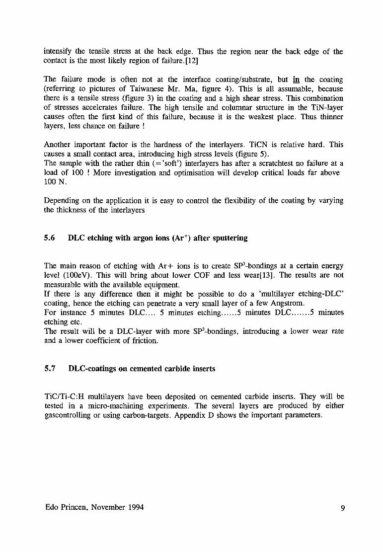
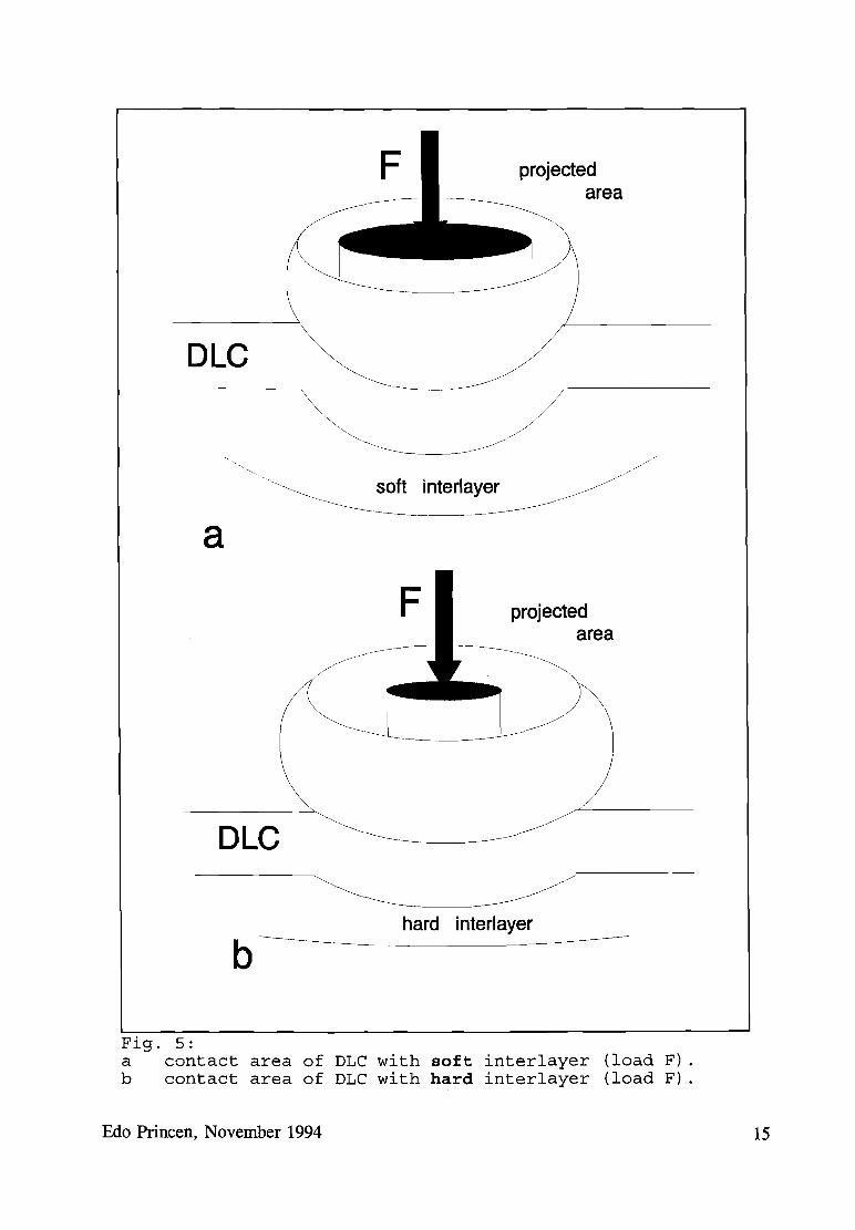
The DLC-toplayers deposited directly on the (hard) TiCN, thus without gradually TiC,don't show any bad adhesion in the scratchtest. Referring to figure 1 (App. A) showing ahard interlayer decreases the contact area but increases the stress as well as the shearstress[lO]. It is this case I agree with the opinion of Prof. Amell (Salford University,U.K.): "It seems that toughness for tribological applications is desirable and it may beworthwhile sacrificing some hardness to give significant increase in toughness".It can be concluded after inspection of scratches that the failure mode with the graduallyTiC layer is less brittle[9] , thus ideal for mechanical applications.
5.4 DLC without nitrogen in final stage
According to Palmier ea. [11] nitrogen favours a decrease of the internal stress level. Thisstatement is not measurable with the available equipment. Personally I think it makes thecoating brittle. Too high amounts of nitrogen might be a reason. After all I think the roleof nitrogen is not enormous and it is just constrained to reactionlayer formation infrictioncases.
5.5 DLC with thinner TiN and TiCN interlayers
Although the interlayers are not a part of the contact area, they are very important for thestress level and failure mode in the coating. DLC, produced with standard procedure,exists of rather thick TiN and TiCN interlayers. Primarily to reduce the internal stresslevel in the coating and to improve the adhesion to the substrate. Depositing these layersthinner, there will be still a reduction of the stress level and the chance on failure (in thescratchtest) will be decreased.
The failure mode in a scratchtest can be made clear in figures 1 and 2 (App. A). Themaximum shear stress occurs on the axis of symmetry at a distance 0.48r below thesurface (r : radius of the contact area).Addition of a tangential traction has three effects. Firstly, the area of maximum shearstress moves forwards and towards the surface as the tangential force is increasing andwill reach the surface at a friction coefficient of 0.3. Secondly, the region of tensile stresswill develop in the surface at the back edge of the contact. Thirdly, the effect of thefrictional traction is to add a compressive stress at the front edge of the contact and to
Edo Princen, November 1994 8
intensify the tensile stress at the back edge. Thus the region near the back edge of thecontact is the most likely region of failure. [12]
The failure mode is often not at the interface coating/substrate, but in the coating(referring to pictures of Taiwanese Mr. Ma, figure 4). This is all assumable, becausethere is a tensile stress (figure 3) in the coating and a high shear stress. This combinationof stresses accelerates failure. The high tensile and columnar structure in the TiN-layercauses often the first kind of this failure, because it is the weakest place. Thus thinnerlayers, less chance on failure!
Another important factor is the hardness of the interlayers. TiCN is relative hard. Thiscauses a small contact area, introducing high stress levels (figure 5).The sample with the rather thin (= 'soft') interlayers has after a scratchtest no failure at aload of 100 ! More investigation and optimisation will develop critical loads far above100 N.
Depending on the application it is easy to control the flexibility of the coating by varyingthe thickness of the interlayers
5.6 DLC etching with argon ions (Ar+) after sputtering
The main reason of etching with Ar+ ions is to create Sp3-bondings at a certain energylevel (lOOeV). This will bring about lower COF and less wear[13]. The results are notmeasurable with the available equipment.If there is any difference then it might be possible to do a 'multilayer etching-DLC'coating, hence the etching can penetrate a very small layer of a few Angstrom.For instance 5 minutes DLC 5 minutes etching 5 minutes DLC 5 minutesetching etc.The result will be a DLC-Iayer with more Sp3-bondings, introducing a lower wear rateand a lower coefficient of friction.
5.7 DLC-coatings on cemented carbide inserts
TiC/Ti-C:H multilayers have been deposited on cemented carbide inserts. They will betested in a micro-machining experiments. The several layers are produced by eithergascontrolling or using carbon-targets. Appendix D shows the important parameters.
Edo Princen, November 1994 9

6 DISCUSSION
At this moment it is clear that role of the interlayers is important. In the past they didn'tget the attentention they should deserve. Other important factors concerning DLC coatingsare:
*
*
*
*
*
*
A very thin unstochiometric, softer TiN (less nitrogen) interlayer to exhibitductility of the coating. The critical load in the scratchtest will probably be higher.
A microwave plasma instead of a RF glow discharge to get more stable processcontrol. Above all it could be possible to sputter with less argon ions in a microwave plasma. By exciting the hydrocarbons with the proper frequency it might bepossible to maintain a plasma with C+ ions ("self-sputtering"), favouring a higherion current density to the substrate.
It is generally known that the amount of hydrogen in DLC is a very importantfactor in resulting the ratio SP3/Sp2 (see chapter 2). Even more important than theamount of hydrogen is the form of hydrogen in DLC.[3]The hydrogen can be unbonded, bonded in SP3 structure or bonded in SP2 structure. The kind of bonding has influence on the coating properties
There might be a relationship between high ion current density and diamond-likecarbon growth. This is not measurable with the available equipment. SEMinvestigation of Nb-C:H, produced by high lCD, showing a very dense structureconfirms this statement. More investigation is definitely necessary.
In the past lots of studies have been done on the influences of gases on diamondgrowth. At this moment it is clear that the presence of even small amounts ofcertain gases can affect the process, e.g. a leak. After comparing the differentprocesses (CVD,PVD,IBAM etc.) of diamond-growth and their relationship withgases. It is very difficult to define relations, because a gas property depends ontemperature and pressure. More investigation is certainly necessary, especially incombination with the kind of powersupply (RF,DC, microwave).
By varying the thickness and hardness of interlayers it is possible to determinesome very important properties of a coating in general. The message from thiswork is that interlayers can be useful in enhancing adhesion, but their structureshould be dictated by the requirements of the application.
Edo Princen, November 1994 10

REFERENCES
1 D.P. Monaghan, D.G. Teer, P.A. Logan, I. Efeoglu, R.D. Amell, Deposition ofwear resistant coatings based on DLC by DBMS, Surface and Coatings Technology, 60 (1993) p525-530
2 K. Bewilogua, H. Dimigen, Preparation of W-C:H coatings by magnetronsputtering, Surface and Coatings Technology, 61 (1993) p144-150
3 J.C. Angus, Diamond and diamond-like films, Thin Solid Films, 216 (1992) p126133
4 H. Dimigen, H. Hiibsch, R. Memming, Tribological and electrical properties ofmetal-containing hydrogenated carbon films, Appl. Phys. Lett, 50 (1987)
5 J. Robertson, The deposition mechanism of diamond-like a-C and a-C:H, Diamondand Related Materials, 3 (1994) p361-368
6 E. Bergmann, J. Vogel, J. Vac. Sci. Techn., 5 (1987) p70
7 o. Knotek, F. L6ffler, W. Burgmer, Amorphous carbon physically vapourdeposited coatings, Surface and Coating Technology, 49 (1991) p370-373
8 Ghosh, Kohler, Surface and Coating Technology, (1992) p54/55
9 S.J. Bull, Failure modes in scratch adhesion testing, Surface and Coating Technology, 50 (1991) p25-32
10 A. Matthews, Engineering applications for diamond-like carbon, Diamond andRelated Materials, 3 (1994) p902/911
11 D. Paulmier, H. Zaidi, H. Nery, T. Le Huu, Tribological behaviour of diamondlike coatings, Surface and Coating Technology, 62 (1993) p570-576
12 Amell, unpublished work.
13 S. Miyake, Tribological properties of hard carbon films, Surface and CoatingTechnology, 54/55 (1992) p563-569
Edo Princen, November 1994 11
APPENDIX A
//
Fig. 1: Iso-stress levels in substrate under normal load.
Edo Princen, November 1994 12

• (
Fig. 2:Iso-stress levels under normal and tangential load(fJ.=O.3)
Edo Princen, November 1994 13

pMEMBRANE STRESS
---- ..---------------
tSUBSTRATE REACTION
Fig. 3: Stress in coating under normal point-load.
DLC
TiC
TiCN
TiN
Tisubstrate
Fig. 4: Coating failure in the coating.
Edo Princen, November 1994 14
DLC
F projectedarea
a
F projectedarea
DLC
b----~hard interlayer------
Fig. 5:a contact area of DLC with soft interlayer (load F) .b contact area of DLC with hard interlayer (load F) .
Edo Princen, November 1994 15

APPENDIX B
Table: Properties of Diamond and OLe Materials (from literature)
Thin Film Bulk
Property CVP Dia a=C a=C:H Diamond Graphite
crystal structure Cubic Amorphous Amorphous Cubic Hexagonal
ao-3.561A mixed sp3 and sp3/sp2 ao-3.567A a-2.47
sp2 bonds
Form Facteted crystals Smooth to rough Smooth - Facted crystals
Hardness Hv 3,000-12,000 1,200-3,000 900-3,000 7,000-10.000
Density 2.8-3.5 1.6-2.2 1.2-2.6 3.51 2.26
Refractive Index 1.5-3.1 1.6-3.1 2.42 2.15
Electrical >1013 >10 10 106_1014 >1016 0.4
Resistivity (ohms/em)
ThermaJ 1100 2000 3500
Conductivity (W/mK)
Chemical Stability Inert Inert Inert Inert Inert
Hydrogen Content (HIC) 0.25-1
Growth Rate -1 2 5 1000
(J.LmIh) (synthetic)
Edo Princen, November 1994 16

APPENDIX C
OUTLINE OF A DEPOSITION PROCEDURE FOR Ti-C:H.
1 Pump to 5 * E-5 Torr
2 Cooling-water on + leaktest
3 Check the nitrogen pressure of 3.5 * E-4 Torr with the needle valve. Read thevalue and close the valve
4 Input argon 3 * E-3 Torr. This pressure needs to be constant during the run.
5 30 minutes cleaning with 2 Ti-targets on 0.2A (ramp)DC substrate bias -1000VRF substrate bias 200W forward power
6 3-4 minutes pure Ti (2 targets 6A each)DC substrate bias -250VRF substrate bias -100V DC-bias
7 20 minutes TiN with nitrogen through the piezo valve.55 % OEM of pure titanium
8 Gradually input of extra nitrogen through the needle valve, see step 3. Inlet ofnitrogen to 3.5 * E-4 Torr.
9 30 minutes TiCN with acetylene (or butane) through the piezo valve. 50% OEMof pure titanium.
10 Gradually decreasing of the OEM reading from 50% to 15% in about 20 minutes.The deposited layer is unstochiometric TiC.
11 Close nitrogen needle-valve and switch off.
12 Leave the system untill the desired DLC thickness is reached (about 40 minutes).
It is necessary to clean the targets after each DLC-run for about 45 minutes with acurrent of 6A.
Edo Princen, November 1994 17

DEPOSITION OF TiC/Ti-C:H MULTILAYERS
Multilayers can be deposited by:
GAS PULSING: x min. OEM 50% ... x min. OEM 15 % .... etc.-fine or thick multilayers with diffuse interfaces
SEQUENTIAL DEPOSITION-thick layers
SIMULTANEOUS DEPOSITON: it is possible to deposit a-C with an extra carbon targetand TiC with the presence of a hydrocarbon gas. Non-continuous sample rotation isrecommended.-fine multilayers with discrete interfaces
GAS PULSING AND SHUTTERING: the target is covered during switching over of theOEM-reading-fine multilayers with discrete interfaces
Edo Princen, November 1994 18

APPENDIXDDLC COMPOSITION ON CEMENTED CARBIDE INSERTS
!RunNum GAS GAS GAS TARGETS bias Ti time TiN time OEM TiCN time OEM DLC time OEM[%)
ber 1 2 3f.po- [W) [min.) [W) [min.) [%) [W] [min.) [%) [W) [min.)
wer
2 Ar N2 C4HlO2 Ti DC-6 Amps 110 I 5 20 I 25 I 55 20 I 30 I
45 20 I 701 I 15/50RF I I I I I I II I I I I I II I I I I I II I I I I I II I I I I I I
3 Ar N2 C4HlO2 Ti DC-6 Amps 125 I 4 20 I 28 I
55 20 I
35 I 45 20 I 60 I15RF I I I I I I I
I I t I I I II I I I I I II I I I I I II I I : I : I
4 Ar N2 C4HlO1 Ti+ 1 C DC-6f1 Amps 114 I 4 20 I 26 I 55 20 I 28
I45 20 I 65 I 50RF I I I I I I I
I I I I I I II I I I I I II I I I I I II I I I I I t
5 Ar N2 C4HlO2 Ti + 1 Nb DC-6f6 Amps 125 I
3 20 I15
I55 20 I 46 I 45 20 I
45 I 13RF I I I I I I II I I I I I II I I I I I II I I I I I I
: I I I I I :6 Ar N2 C4HlO
1 Ti + 1 C DC-6f1 Amps RF 125 3 15 24 55 15 33 45 15 45 15
i
7 Ar N2 C4HlO1 Ti+ 1 C DC-6f1 Amps RF 125 3 15 10 55 15 17 45 15 202 10
1) 5 minutes 50% and 5 minutes 15%. varying for 70 minutes.2) with gradually TiC-layer; in 20 min. from 45% to 10%.
Edo Princen, November 1994 19