Embed Size (px)
Citation preview

Dr
HS
a
ARRAA
KTSRP
1
tWmdmjputta
eo[tIt
0d
Applied Surface Science 256 (2010) 6420–6426
Contents lists available at ScienceDirect
Applied Surface Science
journa l homepage: www.e lsev ier .com/ locate /apsusc
eposition and characterization of TiAlSiN nanocomposite coatings prepared byeactive pulsed direct current unbalanced magnetron sputtering
arish C. Barshilia ∗, Moumita Ghosh, Shashidhara, Raja Ramakrishna, K.S. Rajamurface Engineering Division, National Aerospace Laboratories (CSIR), Post Bag No. 1779, Bangalore 560 017, India
r t i c l e i n f o
rticle history:eceived 8 October 2009eceived in revised form 20 February 2010ccepted 9 April 2010vailable online 18 April 2010
eywords:iAlSiN nanocomposite coatings
a b s t r a c t
This work reports the performance of high speed steel drill bits coated with TiAlSiN nanocompositecoating at different Si contents (5.5–8.1 at.%) prepared using a four-cathode reactive pulsed direct cur-rent unbalanced magnetron sputtering system. The surface morphology of the as-deposited coatings wascharacterized using field emission scanning electron microscopy. The crystallographic structure, chemi-cal composition and bonding structure were evaluated using X-ray diffraction, energy-dispersive X-rayanalysis, X-ray photoelectron spectroscopy, respectively. The corrosion behavior, mechanical proper-ties and thermal stability of TiAlSiN nanocomposite coatings were also studied using potentiodynamic
tructure and propertieseactive magnetron sputteringerformance evaluation
polarization, nanoindentation and Raman spectroscopy, respectively. The TiAlSiN coating thickness wasapproximately 2.5–2.9 �m. These coatings exhibited a maximum hardness of 38 GPa at a silicon contentof approximately 6.9 at.% and were stable in air up to 850 ◦C. For the performance evaluation, the TiAlSiNcoated drills were tested under accelerated machining conditions by drilling a 12 mm thick 304 stainlesssteel plate. Under dry conditions the uncoated drill bits failed after drilling 50 holes, whereas, TiAlSiNcoated drill bits (Si = 5.5 at.%) drilled 714 holes before failure. Results indicated that for TiAlSiN coated
eased
drill bits the tool life incr. Introduction
High speed steel (HSS) is used in the manufacturing of cuttingools (such as drill bits) as it can withstand high temperatures.
hen uncoated drill bits advance into the metallic work piece, theaterial is removed in the form of chips which bind around the
rill bits and cause breakage. In case of coated drill bits, the chipoves over the coating and can be easily removed, preventing the
amming and breakage of the drill bits. Also while drilling, the tem-erature at the contact point between tool and work piece increasesp to 1200 ◦C [1,2]. Uncoated tools cannot be used for such highemperature applications. To meet these conditions, it is necessaryo develop coatings which are wear-resistant and thermally stablet high cutting temperatures.
TiN coatings have been widely used as a protective layer tonhance the lifetime and performance of cutting tools. But thexidation resistance of TiN is limited up to approximately 500 ◦C
3,4]. TiAlN coatings show an improvement in the oxidation resis-ance when compared to TiN coatings (approximately 700 ◦C) [5,6].ncreasing requirements on high speed and dry cutting applica-ions at elevated temperatures are of great importance. This opens∗ Corresponding author. Tel.: +91 80 2508 6494; fax: +91 80 2521 0113.E-mail address: [email protected] (H.C. Barshilia).
169-4332/$ – see front matter © 2010 Elsevier B.V. All rights reserved.oi:10.1016/j.apsusc.2010.04.028
by a factor of more than 14.© 2010 Elsevier B.V. All rights reserved.
up demand for the quality of wear resistant coatings at high tem-peratures. Incorporation of Si into the TiAlN system increasesthe hardness as well as thermal stability (approximately 900 ◦C)[7,8]. Therefore, coatings with quaternary system (e.g., TiAlSiN) areof special interest for high temperature cutting tool applications[9,10].
In the present study, TiAlSiN nanocomposite coatings with dif-ferent Si contents ranging from 5.5 to 8.1 at.% were deposited onvarious substrates such as HSS drill bits, silicon and mild steel (MS)by four-cathode reactive pulsed direct current unbalanced mag-netron sputtering system. We present the mechanical properties,structural and microstructural characterization, chemical compo-sition and corrosion behavior of the TiAlSiN coatings. We have alsostudied the performance of the TiAlSiN coated HSS drill bits.
2. Experimental details
2.1. Preparation of TiAlSiN coatings
TiAlSiN coatings were deposited on HSS drill bits, silicon (1 0 0)
and mild steel substrates using a four-cathode reactive unbalancedpulsed direct current magnetron sputtering system. The details ofthe sputtering system are described elsewhere [11]. Four direct-cooled unbalanced magnetron cathodes (2 Ti, 1 Al and 1 Si) withfeed-throughs mounted horizontally in opposed-cathode configu-
H.C. Barshilia et al. / Applied Surface Science 256 (2010) 6420–6426 6421
Table 1Process parameters for the deposition of TiAlSiN coatings.
Diameter of sputtering gun 0.1524 mAr flow rate 35 sccmN2 flow rate 15 sccmOperating pressure 5.0 × 10⁻⁴ PaAr + N2 pressure 5.0 × 10⁻¹ PaSubstrate temperature 200 ◦CTi target power 500 WAl target power 250 WSi target power 150–200 W
rgstgppalblomIasakstpTotf
2
XE(bcsrtsecmfnaBosrt
sN
Table 2Standard parameters for testing of TiAlSiN coated HSS drill bits.
Testing material SS 304Drill speed 800 rpmFeed rate 0.08 mm/revDrill diameter 8 mm
Si–Si bond (99.15 eV) due to the formation of Si–Ti bond structure[22]. Fig. 1(d) associated with N 1s spectrum of the TiAlSiN coatingrevealed the presence of two peaks at 396.6 and 398.3 eV. The peakat 396.6 eV corresponds to nitrogen in TiN or AlN, as the binding
Table 3Composition of TiAlSiN coatings determined using EDAX analysis.
Sample no. Composition
Bias voltage −75 VThickness of the coating 2.5–2.9 �mSubstrate holder rotation frequency 1 rpm
ation were used for co-sputtering. The diameter of the sputteringuns was 0.1524 m. In order to deposit TiAlSiN coatings, the sub-trates were first degreased using acetone, isopropyl alcohol andrichloroethylene. The substrates were finally dried with dry nitro-en. After loading, the vacuum chamber was evacuated to a baseressure of 5.0 × 10⁻⁴ Pa. This was followed by argon–hydrogenlasma cleaning under an operating pressure of 1.34 Pa for 45 mint a discharge voltage of −800 V, which helps to remove the oxideayer effectively from the metallic substrates [12,13]. To achieveetter adhesion between the coating and the substrate, an inter-
ayer of Ti with a thickness of approximately 0.3 �m was depositedn the substrates. During Ti interlayer deposition, argon flow wasaintained at 35 sccm and the voltage was maintained at −125 V.
n order to deposit TiAlSiN coatings, two Ti targets (99.99% purity),n Al target (99.99% purity), and a Si target (99.99% purity) wereputtered in Ar (99.999% purity) and N2 (99.999% purity) plasmat an operating pressure of 5.0 × 10⁻¹ Pa. The flow rate of N2 wasept constant at 15 sccm. All the coatings were prepared at a sub-trate temperature of 200 ◦C and an infrared lamp, fixed behindhe substrate holder, was used for substrate heating. Coatings wererepared at different Si contents by varying power to the Si target.he coating thickness was approximately 2.5–2.9 �m. In order tobtain uniform coating on drill bits and other substrates a plane-ary substrate rotation was employed. The deposition conditionsor TiAlSiN coatings are listed in Table 1.
.2. Characterization of the coatings
The bonding structure of the coatings was characterized by-ray photoelectron spectroscopy (XPS, V.G. Microtech) using anSCA 3000 system with a monochromatic Al K� X-ray beamenergy = 1486.5 eV and power = 150 W). The C 1s peak with ainding energy of 285.0 eV was used to make correction for theharge shift. Sputter cleaning was not performed for the XPS mea-urements. X-ray diffraction (XRD) patterns of the coatings wereecorded in a Rigaku D/max 2200 Ultima thin film X-ray diffrac-ometer using a Cu K� radiation (� = 0.15418 nm). Microstructuraltudies and thickness measurements were carried out using fieldmission scanning electron microscopy (FESEM, Carl Zeiss). Theomposition of the coatings was measured using an Oxford Instru-ents energy dispersive X-ray analysis (EDAX). The detector area
or EDAX measurements was 30 mm2, which provided large sig-al/noise ratio. The hardness measurements were performed innanoindenter (CSEM Instruments) at a load of 5 mN using a
erkovich diamond indenter. Before indentation, the samples werebserved under an optical microscope and a suitable area was cho-en. Ten indentations were made on the sample and the values
eported herein represent the average of ten values. More details ofhe nanoindentation measurements are described elsewhere [14].The corrosion behavior of the coatings deposited on mild steelubstrate was studied using potentiodynamic polarization in 3.5%aCl solution under free-air condition at room temperature. The
Drilling depth 12 mmTime for drilling each hole 11 sPenetration rate 64 mm/min
experimental conditions for the polarization measurements aredescribed elsewhere [15]. The corrosion potential (Ecorr), the cor-rosion current density (icorr) and the polarization resistance (Rp)were deduced from the Tafel plots (log i vs. E). In order to testthe thermal stability of the coatings, silicon substrates coated withTiAlSiN were heated in air in a resistive furnace at temperatures inthe range 750–1000 ◦C. The structural changes of the coatings as aresult of heating were measured using micro-Raman spectroscopy.A DILOR-JOBIN-YVON-SPEX integrated micro-Raman spectrome-ter was used for the present study [16]. Drilling tests were carriedout using an automated Oerlikron make radial drilling machine. Inorder to determine the performance, the uncoated drill bits and thedrill bits coated with TiAlSiN were used to drill a 12 mm thick SS304 plate. The standard test parameters are summarized in Table 2.After drilling operation, the TiAlSiN coatings on the margins, cut-ting edges, and lips of the drills were observed under an opticalmicroscope.
3. Results and discussion
3.1. Chemical composition and chemical structure
TiAlSiN nanocomposite coatings prepared at Si contents of 5.5,6.9 and 8.1 at.% are denoted as Sample nos. 1, 2 and 3, respectively.The relative composition of the as-deposited TiAlSiN coatings withdifferent Si contents as determined from EDAX is presented inTable 3. The EDAX data also showed trace amounts of argon andoxygen in the coatings.
Fig. 1 shows the high-resolution core level spectra for theTiAlSiN coatings with Si content of 5.5 at.%. In Fig. 1(a), deconvo-lution of the Ti 2p peak indicated that it was composed of fourpeaks centered at binding energy values of 456.9, 458.7, 461.6 and464.0 eV. The peaks centered at 456.9 and 461.6 eV originate from Ti2p3/2 and Ti 2p1/2 electrons in titanium oxynitride [11,17]. The twopeaks centered at 458.7 and 464.0 eV correspond to Ti 2p3/2 and Ti2p1/2 electrons respectively in TiO2 [18,19]. Fig. 1(b) shows the XPScore level spectrum of Al 2p with a peak centered at 74.1 eV, whichcorresponds to AlN [17,20]. The Si 2p spectrum showed a charac-teristic peak of Si3N4 at a binding energy of 100.8 eV as shown inFig. 1(c) [20–22]. The origin of a very low intensity peak centered ata binding energy of approximately 97.0 eV, shown in Fig. 1(c), maybe attributed to the formation of SiTix phase as the Si 2p compo-nent shifts gradually to lower binding energies relative to that of
Ti Al Si N Ar O
1 24.5 at.% 11.9 at% 5.5 at% 56.7 at.% 1.0 at.% 0.4 at.%2 23.1 at.% 11.9 at.% 6.9 at.% 56.5 at.% 1.6 at.% –3 21.2 at.% 10.8 at.% 8.1 at.% 57.2 at.% 1.8 at.% 0.9 at.%

6422 H.C. Barshilia et al. / Applied Surface Science 256 (2010) 6420–6426
l 2p, (c
eTw55i
3
dvo
Fe
Fig. 1. XPS core-level spectra of: (a) Ti 2p, (b) A
nergies of TiN and AlN have been reported to be very similar [23].he peak at 398.3 eV corresponds to Si3N4 [24]. Fig. 1(e) associatedith O 1s spectrum consists of two peaks centered at 529.6 and
31.8 eV. The high intensity peak centered at a binding energy of31.8 eV corresponds to oxygen in titanium oxynitride and the low
ntensity peak at 529.6 eV corresponds to oxygen in TiO2 [18].
.2. Structural characterization
Fig. 2 shows the XRD patterns of TiAlSiN coatings prepared atifferent Si contents. The weak diffraction peaks observed at 2�alues of 36.6◦ and 42.2◦ correspond to (1 1 1) and (2 0 0) planesf TiAlSiN with cubic B1 NaCl structure. The peaks centered at
ig. 2. XRD patterns of TiAlSiN coatings deposited on silicon substrates with differ-nt Si contents: (a) 5.5, (b) 6.9 and (c) 8.1 at.%.
) Si 2p, (d) N 1s and (e) O 1s of TiAlSiN coating.
2� = 34.8◦, 38.1◦ and 40.0◦ correspond to hcp Ti (0 1 0), (0 0 2) and(0 1 1) planes, respectively. These diffractions originate from the Tiinterlayer, which was incorporated for improved adhesion of thecoatings, as discussed previously. A high intensity peak centered at2� ≈ 32.6–32.9◦ originates from Si substrate, which was consistedof a pristine SiO2 layer. This was confirmed by taking XRD data ofan uncoated Si substrate. As the Si content increased, the intensityof the diffraction peaks decreased and a significant broadening ofthe peaks was also noticed. This can be attributed to an increase inamorphous content and diminution of grain size with the additionof Si [25,26]. The average grain size for the coatings with differ-ent Si contents was determined from the broadening of the XRDpeak using Debye-Scherrer formula [25]. The grain size decreasedfrom 7.5 to 5.0 nm for Si contents of 5.5–8.1 at.%, respectively. Inaddition to a decrease in the grain size, the residual stress in crys-tal lattice also contributes to broadening of the diffraction peaks[27,28].
3.3. Microstructural and surface morphological studies
Fig. 3 shows the FESEM micrographs of the as-deposited TiAlSiNcoatings. Fig. 3(a)–(c) shows the surface microstructure of as-deposited TiAlSiN coatings with Si contents of 5.5, 6.9 and 8.1 at.%,respectively. It is clear from the microstructures that as the Sicontent increases from 5.5 to 8.1 at.% the coatings exhibit a finegrained morphology. Fig. 3(d) and (e) shows the cross-sectionalmicrographs of as-deposited TiAlSiN coatings with Si contents of5.5 and 8.1 at.%. A columnar morphology is partially visible for theTiAlSiN coating prepared at low Si content. With an increase in theSi content to 8.1 at.% the columnar morphology reduced consid-erably [28–31]. These results were further confirmed by atomicforce microscopy images, which showed decrease in root meansquare roughness of the TiAlSiN coatings from 25 to 20 nm withan increase in Si content from 5.5 to 8.1 at.%. Addition of Si stopsthe grain growth and stimulates a re-nucleation of grains, which
results in a non-columnar morphology [29]. It is widely estab-lished that addition of amorphous phase in a nano-crystalline phaseaffects the columnar structure and crystallite size, which determinethe surface morphologies of the nanocomposite coatings [28,29].For example, it has been reported that the unbalanced magnetron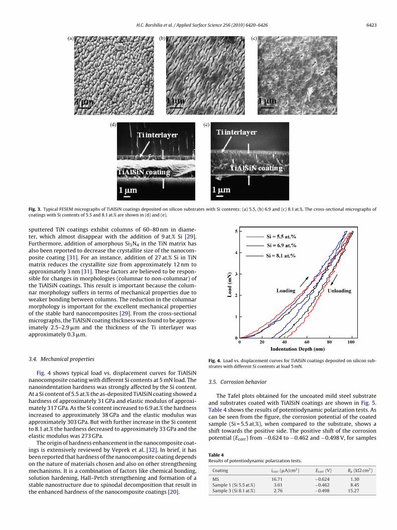
H.C. Barshilia et al. / Applied Surface Science 256 (2010) 6420–6426 6423
F ates with Si contents: (a) 5.5, (b) 6.9 and (c) 8.1 at.%. The cross-sectional micrographs ofc
stFapmastnwmomia
3
nnAhmiate
ibomsst
can be seen from the figure, the corrosion potential of the coatedsample (Si = 5.5 at.%), when compared to the substrate, shows ashift towards the positive side. The positive shift of the corrosionpotential (Ecorr) from −0.624 to −0.462 and −0.498 V, for samples
Table 4Results of potentiodynamic polarization tests.
ig. 3. Typical FESEM micrographs of TiAlSiN coatings deposited on silicon substroatings with Si contents of 5.5 and 8.1 at.% are shown in (d) and (e).
puttered TiN coatings exhibit columns of 60–80 nm in diame-er, which almost disappear with the addition of 9 at.% Si [29].urthermore, addition of amorphous Si3N4 in the TiN matrix haslso been reported to decrease the crystallite size of the nanocom-osite coating [31]. For an instance, addition of 27 at.% Si in TiNatrix reduces the crystallite size from approximately 12 nm to
pproximately 3 nm [31]. These factors are believed to be respon-ible for changes in morphologies (columnar to non-columnar) ofhe TiAlSiN coatings. This result is important because the colum-ar morphology suffers in terms of mechanical properties due toeaker bonding between columns. The reduction in the columnarorphology is important for the excellent mechanical properties
f the stable hard nanocomposites [29]. From the cross-sectionalicrographs, the TiAlSiN coating thickness was found to be approx-
mately 2.5–2.9 �m and the thickness of the Ti interlayer waspproximately 0.3 �m.
.4. Mechanical properties
Fig. 4 shows typical load vs. displacement curves for TiAlSiNanocomposite coating with different Si contents at 5 mN load. Theanoindentation hardness was strongly affected by the Si content.t a Si content of 5.5 at.% the as-deposited TiAlSiN coating showed aardness of approximately 31 GPa and elastic modulus of approxi-ately 317 GPa. As the Si content increased to 6.9 at.% the hardness
ncreased to approximately 38 GPa and the elastic modulus waspproximately 303 GPa. But with further increase in the Si contento 8.1 at.% the hardness decreased to approximately 33 GPa and thelastic modulus was 273 GPa.
The origin of hardness enhancement in the nanocomposite coat-ngs is extensively reviewed by Veprek et al. [32]. In brief, it haseen reported that hardness of the nanocomposite coating depends
n the nature of materials chosen and also on other strengtheningechanisms. It is a combination of factors like chemical bonding,olution hardening, Hall–Petch strengthening and formation of atable nanostructure due to spinodal decomposition that result inhe enhanced hardness of the nanocomposite coatings [20].
Fig. 4. Load vs. displacement curves for TiAlSiN coatings deposited on silicon sub-strates with different Si contents at load 5 mN.
3.5. Corrosion behavior
The Tafel plots obtained for the uncoated mild steel substrateand substrates coated with TiAlSiN coatings are shown in Fig. 5.Table 4 shows the results of potentiodynamic polarization tests. As
Coating icorr (�A/cm2) Ecorr (V) Rp (k� cm2)
MS 16.71 −0.624 1.30Sample 1 (Si 5.5 at.%) 3.61 −0.462 8.45Sample 3 (Si 8.1 at.%) 2.76 −0.498 15.27

6424 H.C. Barshilia et al. / Applied Surface Science 256 (2010) 6420–6426
FS
wrdcrt2ttipars
3
toawTFica14tAt
aRodppwItcf9fi
In engineering design and manufacturing industries, metal cut-ting is an essential process. Power consumed in metal cutting islargely converted into heat near the work piece and cutting toolinterface. The cost of machining is strongly dependent on the rate ofmetal removal and costs may be reduced by increasing the cutting
ig. 5. Potentiodynamic polarization curves of mild steel and TiAlSiN coatings withi contents of 5.5 and 8.1 at.%.
ith Si = 5.5 at.% and Si = 8.1 at.%, respectively, indicates better cor-osion resistance of the TiAlSiN coated samples. Corrosion currentensity is an important parameter to evaluate the kinetics of theorrosion reactions. The corrosion rate is proportional to the cor-osion current density measured by polarization. The decrease inhe corrosion current from 16.71 × 10⁻⁶ A/cm2 to 3.61× 10⁻⁶ and.76 × 10−6 A/cm2, for Samples 1 and 3, respectively, indicates bet-er corrosion resistance of the TiAlSiN coated samples comparedo the uncoated mild steel substrate. The polarization resistancencreases from 1.30 k� cm2 to 8.45 and 15.27 k� cm2 for sam-les with Si = 5.5 at.% and Si = 8.1 at.%, respectively. Increase in Rp
lso indicates improvement in the corrosion resistance. The aboveesults show that TiAlSiN coated substrates exhibit a better corro-ion resistance compared to the uncoated mild steel substrates.
.6. Thermal stability
For hard nanocomposite coatings the thermal stability at higheremperatures is very important. This is because these coatings areften used at high temperature conditions. The high temperaturepplication of cutting tools results in oxidation of the coatings,hich affects their wear resistance [33]. The thermal stability of
iAlSiN coatings was studied using micro-Raman spectroscopy.ig. 6 shows the Raman spectra of as-deposited TiAlSiN coat-ngs with different Si contents. The Raman spectrum of TiAlSiNoatings show two broad bands centered approximately at 220nd 560 cm−1. These bands correspond to acoustic mode in the50–350 cm−1 region (LA and TA) and the optic modes in the00–650 cm−1 region (LO and TO), respectively [34]. Scattering inhe acoustic range is due to the vibrations of the heavy metal (Ti,l, etc.) ions and that in the optic range is due to the vibrations of
he light element (N) ions [35,16].Fig. 7 shows the Raman spectra of TiAlSiN coatings heat treated
t different temperatures. There was no significant change in theaman spectra after heating the sample up to a temperaturef 850 ◦C. The width of the optic mode increased and intensityecreased with increase in temperature. The optic mode disap-eared completely at 900 ◦C. At a temperature of 900 ◦C, additionaleaks at 449, 520, 641, 866 and 992 cm−1 were observed. Theeak peak at 449 cm−1 is assigned to the rutile phase of TiO2 [16].
ntensity of this peak increased with an increase in the annealing
emperature. This indicates the onset of oxidation of the TiAlSiNoatings at 900 ◦C. The weak peak centered at 520 cm−1 originatesrom Si substrate [36]. The broad peaks centered at 641, 866 and92 cm−1 originate from Al2O3 [16,37]. The Raman data thus con-rms that the TiAlSiN coatings of the present study were stableFig. 6. Raman spectra of as-deposited TiAlSiN coatings deposited on silicon sub-strates with Si contents: (a) 5.5 (b) 6.9 and (c) 8.1 at.%.
upto 850 ◦C. The assignments of the Raman peaks observed in theas-deposited and heat-treated TiAlSiN coatings are listed in Table 5.
3.7. Performance evaluation
Fig. 7. Raman spectra of as-deposited TiAlSiN coatings deposited on silicon sub-strates with Si content of 5.5 at.% and coatings heat treated at 750, 800, 850, 900,950 and 1000 ◦C.

H.C. Barshilia et al. / Applied Surface Science 256 (2010) 6420–6426 6425
Table 5Assignment of Raman peaks in as-deposited and heat-treated TiAlSiN coatings.
Sample Peak position (cm−1) Peak assignment Ref.
TiAlSiN (a) As-deposited 220 (B) Longitudinal and transverse acoustic [34]560 (B) Longitudinal and transverse optic [34]
(b) Heat-treated at temperature >900 ◦C 449 (W) TiO2 (Rutile) [16]520 (W) Si [16]641 (B) Al2O3 [16,37]866 (B) Al2O3 [16,37]992 (B) Al2O3 [16,37]
B: broad; W: weak.
rillin
sa[ficmoctd
tc3caT7iTou
ping of the material. This resulted in poor surface finish of the drilledholes and jamming of the drill bit in the holes. Hence the drill bitwas taken out of the drilling process. Fig. 10 shows the roughnessof the drilled holes using Sample 1, Sample 2 and uncoated drill
Table 6Wear measurements of TiAlSiN coated HSS drill bit with Si content of 5.5 at.%.
Holes drilled Wear
350 Chisel wear: 0.24 mmLip wear: 0.31 mmCorner radius: 0.25 mm
700 Chisel wear: 0.39 mm
Fig. 8. Photographs of TiAlSiN coated HSS drill bit after d
peed and/or the feed rate. However, there are limits to the speednd feed beyond which the life of the tool is shortened excessively26,38]. When cutting very hard materials like stainless steel, suf-cient high temperatures are reached resulting in the cracking andhipping of the cutting tool edge. In order to evaluate the perfor-ance of TiAlSiN coated HSS drill bits, drilling tests were carried
ut on a 12 mm thick stainless steel (SS 304) material under dryonditions. Drilling was done using HSS drill bit having a diame-er of 8 mm. After the drilling experiments, the roughnesses of therilled holes were measured by a Mitutoyo roughness tester.
Under dry conditions, Sample 1 (5.5 at.% Si) drilled 714 holeshrough SS 304 plate. Fig. 8 shows the photographs of the chisel,orner radius and lip of TiAlSiN coated HSS drill bit (Sample 1) after50, 700 and 714 holes. Table 6 provides the wear values of thehisel edge, lip and corner radius. After drilling 350 holes, weart the chisel edge, lip and corner radius was very less (Fig. 8 andable 6). Partial removal of the coating was observed after drilling
00 holes and the cutting lip got slightly blunt. However, the qual-ty of the drilled holes was still good. After drilling 714 holes, theiAlSiN coated drill bit was totally blunt and therefore was takenut of the drilling process. Sample 2 (6.9 at.% Si) drilled 320 holesnder same testing conditions before becoming blunt. Under the
g (a) 350, (b) 700 and (c) 714 holes under dry condition.
same testing parameters, the uncoated HSS drill bits could drillonly 50 holes. The performance graph of Sample 1, Sample 2 andan uncoated drill bit is shown in Fig. 9. The uncoated drill bitsshowed damage on the lips and chisel edge which led to the chip-
Lip wear: 0.45 mmCorner radius: 0.52 mm
714 Chisel wear: 0.66 mmLip wear: 0.61 mmCorner radius: 0.85 mm

6426 H.C. Barshilia et al. / Applied Surface
Fig. 9. Performance graph of uncoated and coated with TiAlSiN HSS drill bit with Sicontents of 5.5 and 6.9 at.%.
Fd
bS
4
irsiAcnidsmdb
[
[[
[[
[
[[
[
[[[
[[[[[
[[[
[
[
[
[[[[36] H.C. Barshilia, N. Selvakumar, K.S. Rajam, A. Biswas, Solar Energy Mater. Solar
ig. 10. Roughness values of drilled holes with uncoated and TiAlSiN coated HSSrill bits.
it. Test results for Sample 3 showed similar results as those forample 2.
. Conclusions
Approximately 2.5–2.9 �m thick nanocomposite TiAlSiN coat-ngs with different Si contents were prepared using four-cathodeeactive pulsed direct current unbalanced magnetron sputteringystem on commercially available HSS drill bits, mild steel and sil-con substrates. The TiAlSiN coatings exhibited B1–NaCl structure.
maximum hardness of approximately 38 GPa was obtained at a Siontent of 6.9 at.%. The Raman data of the TiAlSiN coatings showedo phase transformation upto 850 ◦C in air, indicating that the coat-
ngs were stable up to 850 ◦C. The performance of the TiAlSiN coated
rill bits was evaluated by drilling holes in a 12 mm thick stainlessteel plate (SS 304). The results indicate a significant enhance-ent in the performance of the TiAlSiN coated HSS drill bits andry drilling of SS 304 was possible with TiAlSiN coated HSS drillits.
[
[
Science 256 (2010) 6420–6426
Acknowledgements
The authors thank the Director, NAL (CSIR) for allowing to pub-lish these results. Mr. Praveen Kumar is thanked for performanceevaluation tests and Mr. Siju and Mr. Manikandanath N.T. arethanked for FESEM and Raman measurements. This work was sup-ported by the Council of Scientific and Industrial Research, NewDelhi (Grant Nos. FAC-00-01-11 and NWP-00-51-03), India.
References
[1] R.F. Silva, J.M. Gomes, A.S. Miranda, J.M. Vieira, Wear 148 (1991) 69.[2] S.-T. Buljan, S.F. Wayne, Wear 133 (1989) 309.[3] W.D. Sproul, J. Vac. Sci. Technol. A 4 (1986) 2874.[4] W.D. Sproul, R. Rothstein, Thin Solid Films 126 (1985) 257.[5] S. Hofmann, H.A. Jehn, Surf. Interf. Anal. 12 (1988) 329.[6] D. McIntyre, J.E. Greene, G. Hakansson, J.E. Sundgren, W.-D. Munz, J. Appl. Phys.
67 (1990) 1542.[7] S. PalDey, S.C. Deevi, Mater. Sci. Eng. A 342 (2003) 58.[8] S. Carvalho, L. Rebouta, A. Cavaleiro, L.A. Rocha, J. Gomes, E. Alves, Thin Solid
Films 398–399 (2001) 391.[9] F. Vaz, L. Rebouta, M. Andritschky, M.F. da Silva, J.C. Soares, J. Eur. Ceram. Soc.
17 (1997) 1971.10] F. Vaz, L. Rebouta, M. Andritschky, M.F. da Silva, J.C. Soares, Surf. Coat. Technol.
98 (1998) 912.11] H.C. Barshilia, K. Yogesh, K.S. Rajam, Vacuum 83 (2009) 427.12] N. Korner, E. Beck, A. Dommann, N. Onda, J. Ramm, Surf. Coat. Technol. 76–77
(1995) 731.13] J.H. Hsieh, L.H. Fong, S. Yi, G. Metha, Surf. Coat. Technol. 112 (1999) 245.14] H.C. Barshilia, M.S. Prakash, D.V.S. Rao, K.S. Rajam, Surf. Coat. Technol. 195
(2005) 147.15] V.K.W. Grips, H.C. Barshilia, V.E. Selvi, K.S. Rajam, Thin Solid Films 514 (2006)
204.16] H.C. Barshilia, K.S. Rajam, J. Mater. Res. 19 (2004) 3196.17] A. Vennemann, H.-R. Stock, J. Kohlscheen, S. Rambadt, G. Erkens, Surf. Coat.
Technol. 174–175 (2003) 408.18] H.C. Barshilia, N. Selvakumar, K.S. Rajam, D.V.S. Rao, K. Muraleedharan, Thin
Solid Films 516 (2008) 6071.19] I. Bertoti, M. Mohai, J.L. Sullivan, S.O. Saied, Appl. Surf. Sci. 84 (1995) 357.20] D. Yu, C. Wang, X. Cheng, F. Zhang, Thin Solid Films 517 (2009) 4950.21] B.-S. Yau, J.-L. Huang, H.-H. Lu, P. Sajgalik, Surf. Coat. Technol. 194 (2005)
119.22] Y. Fu, H. Du, S. Zhang, W. Huang, Mater. Sci. Eng. A 403 (2005) 25.23] I. Bertoti, Surf. Coat. Technol. 151–152 (2002) 194.24] C.-L. Chang, J.-W. Lee, M.-D. Tseng, Thin Solid Films 517 (2009) 5231.25] B.D. Cullity, Elements of X-ray Diffraction, Addison-Wesley, Reading, 1978.26] J.S. Kim, G.J. Kim, M.C. Kang, J.W. Kim, K.H. Kim, Surf. Coat. Technol. 193 (2005)
249.27] Y.H. Yoo, D.P. Le, J.G. Kim, S.K. Kim, P.V. Vinh, Thin Solid Films 516 (2008) 3544.28] M. Diserens, J. Patscheider, F. Levy, Surf. Coat. Technol. 108 (1998) 241.29] A. Cavaleiro, J.T.M. De Hosson, Nanostructured Coatings, Springer, New York,
2006.30] N. Jiang, Y.G. Shen, Y-W. Mai, T. Chan, S.C. Tung, Mater. Sci. Eng. B106 (2004)
163.31] H.C. Barshilia, B. Deepthi, A.S. Arun Prabhu, K.S. Rajam, Surf. Coat. Technol. 201
(2006) 329.32] S. Veprek, M.G.J. Veprek-Heijman, P. Karvankova, J. Prochazka, Thin Solid Films
476 (2005) 1.33] J.A. Sue, T.P. Chang, Surf. Coat. Technol. 76–77 (1995) 61.34] W. Spengler, R. Kaiser, Solid State Commun. 18 (1976) 881.35] M. Franck, J.-P. Celis, J.R. Roos, J. Mater. Res. 10 (1995) 119.
Cells 92 (2008) 495.37] A. Misra, H.D. Bist, M.S. Navati, R.K. Thareja, J. Narayan, Mater. Sci. Eng. B 79
(2001) 49.38] E.M. Trent, P.K. Wright, Metal Cutting, 4th edition, Butterworth-Heinemann,
Boston, 2000.


![Nanocomposite [5]](https://img.dokumen.tips/doc/110x75/577c7ecf1a28abe054a26499/nanocomposite-5.jpg)


