Embed Size (px)
Citation preview

Document version 1.2
Deployment Guide
Deploying the BIG-IP LTM with IBM WebSphere 8Welcome to the F5 Deployment Guide for IBM® WebSphere. This document provides guidance for deploying the BIG-IP Local Traffic Manager (LTM) with IBM WebSphere 8.
The BIG-IP system can optimize IBM WebSphere at many layers: in front of the IBM HTTP Servers, between HTTP Servers and WebSphere Application Servers, or to eliminate the HTTP layer altogether. By configuring the BIG-IP LTM system within the WebSphere infrastructure F5 provides a number of benefits, including simplification of the infrastructure, application level health monitoring, SSL offload and intelligent load balancing. While high availability remains the central goal of BIG-IP LTM, reducing complexity in an another complex environment allows organizations to spend more time on the important aspects of the architecture such as application delivery, intelligent reporting, and gathering granular statistics from the environment.
Why F5
• Reduces the complexity of WebSphere deployments, including removing the need for an additional HTTP layer.
• Ensures application health by determining the availability of a specific application based on the URI being requested and the port used by the application.
• Enables better visibility through analytics, and provides a granular understanding of how many sessions are established to each WebSphere Application server and the ability to limit these sessions using various metrics.
• Reduces the load on the WebSphere servers by taking on the following tasks:
» SSL processing: the BIG-IP system terminates SSL requests at the front end and delivers HTTP requests to the backend.
» TCP optimizations: the BIG-IP system reduces the number of requests to the servers using HTTP Request and Content caching.
» Connection pooling: The OneConnect feature on the BIG-IP system reduces the number of server-side connections that a server must open by using existing server-side connections for multiple new client-side requests.
For more information of IBM WebSphere see: http://www-01.ibm.com/software/webservers/appserv/was/features/ For more information on the F5 BIG-IP system, see http://www.f5.com/products/big-ip
What's inside:
2 Products and versions tested
2 Prerequisites and configuration notes
3 Deployment scenarios
4 Scenario 1: Configuring the BIG-IP LTM as an HTTP Proxy for IBM WebSphere
11 Scenario 2: Configuring the BIG-IP LTM for WebSphere 8 Web Tier
15 Scenario 3: Configuring the BIG-IP LTM for the HTTP Tier and the WebSphere Application Tier
18 Configuring BIG-IP ASM for WebSphere
20 Appendix: Optional dynamic health monitor for Scenario 1
25 Document Revision History
DEPLOYMENT GUIDE IBM WebSphere 8
2
To provide feedback on this deployment guide or other F5 solution documents, contact us at [email protected].
Products and versions tested
Product Version
BIG-IP LTM 11.1 HF-2
IBM WebSphere 8 and 8.5
Important: Make sure you are using the most recent version of this deployment guide, found at http://www.f5.com/pdf/deployment-guides/ibm-websphere-8-dg.pdf.
Prerequisites and configuration notes
The following are general prerequisites and configuration notes for this guide:
h The configuration in this guide was tested with IBM WebSphere 8 servers in Network Deployment mode with a single Application Profile and two Enterprise applications installed.
h If you are using the BIG-IP advanced monitor for SNMP, SNMP services must be enabled on your WebSphere Application Server per the instructions in this guide.
h If you are using the BIG-IP system to act as an HTTP proxy and eliminate the need for a separate HTTP tier, you need the following information from your WebSphere implementation.
» URIs associated with each WebSphere application
» Ports associated with each WebSphere application
» Host name and/or IP addresses of the WebSphere Application Server hosting each application.
For more information, including where to find this information, see Creating the iRule on page 8.
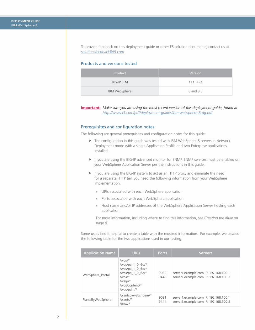
Some users find it helpful to create a table with the required information. For example, we created the following table for the two applications used in our testing.
Application Name URIs Ports Servers
WebSphere_Portal
/wps/*/wps/pa_1_0_6d/*/wps/pa_1_0_6e/*/wps/pa_1_0_6c/*/wps/*/wsrp/*/wps/content/*/wps/pdm/*
90809443
server1.example.com IP: 192.168.100.1 server2.example.com IP: 192.168.100.2
PlantsByWebSphere/plantsbywebshpere/*/plants/*/pbw/*
90819444
server1.example.com IP: 192.168.100.1 server2.example.com IP: 192.168.100.2

DEPLOYMENT GUIDE IBM WebSphere 8
3
Deployment scenarios
One of the fundamental ideas covered in this architecture and deployment is the separation of the Web, Application and Data tiers. The IBM HTTP Server is acting on the Web tier while the WebSphere software is the Application tier. This Application tier then interfaces with the Data tier to provide a full and rich application experience.
Clients
Internet
DMZ
IBM HTTP Servers
Internal
Web Tier Application/Data Tier
IBM WebSphereApplication Servers
There are three different deployment scenarios described in this guide in which the BIG-IP system can be configured. Follow the instructions for the scenario appropriate to your desired configuration:
1. Configuring the BIG-IP LTM as an HTTP proxy The BIG-IP system can reduce complexity in WebSphere environments by acting as the HTTP proxy. This enables benefits such as better application health monitoring, more visibility into the environment, more granular statistics gathering, and removes the need for the additional HTTP layer that only proxies connections to the back-end.
To configure this scenario, see Scenario 1: Configuring the BIG-IP LTM as an HTTP Proxy for IBM WebSphere on page 4
2. Configuring the BIG-IP LTM to load balance the IBM HTTP servers The BIG-IP system can provide intelligent load balancing and health monitoring to the IBM HTTP servers. The IBM HTTP servers direct traffic to the WebSphere application servers.
To configure this scenario, see Scenario 2: Configuring the BIG-IP LTM for WebSphere 8 Web Tier on page 11.
3. Configuring the BIG-IP LTM to load balance the IBM HTTP servers and WebSphere application servers The BIG-IP system can be located in front of the HTTP layer as well as between the HTTP layer and the WebSphere application servers. This enables additional visibility, statistics gathering and better health monitoring.
To configure this scenario, see Scenario 3: Configuring the BIG-IP LTM for the HTTP Tier and the WebSphere Application Tier on page 15.

DEPLOYMENT GUIDE IBM WebSphere 8
4
Scenario 1: Configuring the BIG-IP LTM as an HTTP Proxy for IBM WebSphere
In this section, we configure the BIG-IP LTM to act as an HTTP proxy. Because the BIG-IP LTM is acting as the HTTP proxy, the HTTP Tier of the deployment can be eliminated altogether.
Clients
Internet
BIG-IPLocal Traffic Manager
1 2
3
WebSphere Application Server 6WebSphere Application Server 5WebSphere Application Server 4
pool_gbw for URI /wps/*Application port: 9081
WebSphere Application Server 1
WebSphere Application Server 2
WebSphere Application Server 3
pool_pbw for URI /PlantsByWebSphere/*Application port: 9080
The traffic flow is as follows:
1. Client requests the URL http://www.example.com/PlantsByWebSphere/promo.jsf. This address resolves to the virtual server address on the BIG-IP system.
2. Based on the URI, the BIG-IP system sends the client request to the load balancing pool pool_pbw, serving port 9080.
3. The request is received by an available WebSphere application server in pool_pbw.
Also see Appendix: Optional dynamic health monitor for Scenario 1 on page 20.
Gathering the WebSphere application information
In order to configuring the BIG-IP system to eliminate the need for a separate HTTP Tier, you need the following information from your WebSphere implementation, as described in the prerequisites:
• URIs associated with each WebSphere application
• Ports associated with each WebSphere application
• Host name and IP addresses of the WebSphere Application Server hosting each application.
There are two ways of obtaining this information, depending on whether you have previously configured the IBM HTTP server with your WebSphere Application server or not.
If you have not previously configured the IBM HTTP serverIf you have not previously configured the IBM HTTP server as a part of a WebSphere Application server deployment, you must manually gather this information from your WebSphere implementation. For information on how to find this information, see the IBM documentation.
If you have previously configured the IBM HTTP server If you have previously configured the IBM HTTP Server with your WebSphere Application Server, you can find the required information in the plugin-cfg.xml file.
The URIs are found in the URIGroup statements of the file. UriGroup statements group selected URIs together for the applications deployed within WebSphere. Locate the URIGroup Name that matches the relevant Application.

DEPLOYMENT GUIDE IBM WebSphere 8
5
In the following example from the plugin-cfg.xml file, the URIs for our two are shown in bold.
<UriGroup Name="default_host_WebSphere_Portal_URIs">
<Uri AffinityCookie="JSESSIONID" AffinityURLIdentifier="jsessionid" Name="/wps/PA_1_0_6D/*"/>
<Uri AffinityCookie="JSESSIONID" AffinityURLIdentifier="jsessionid" Name="/wps/PA_1_0_6E/*"/>
<Uri AffinityCookie="JSESSIONID" AffinityURLIdentifier="jsessionid" Name="/wps/PA_1_0_6C/*"/>
<Uri AffinityCookie="JSESSIONID" AffinityURLIdentifier="jsessionid" Name="/wps/*"/>
<Uri AffinityCookie="JSESSIONID" AffinityURLIdentifier="jsessionid" Name="/wsrp/*"/>
<Uri AffinityCookie="JSESSIONID" AffinityURLIdentifier="jsessionid" Name="/wps/content/*"/>
<Uri AffinityCookie="JSESSIONID" AffinityURLIdentifier="jsessionid" Name="/wps/pdm/*"/>
...
</UriGroup>
...
<UriGroup Name="default_host_PlantsByWebSphere_URIs">
<Uri AffinityCookie="JSESSIONID" AffinityURLIdentifier="jsessionid" Name="/plantsbywebsphere/*"/>
<Uri AffinityCookie="JSESSIONID" AffinityURLIdentifier="jsessionid" Name="/pbw/*"/>
<Uri AffinityCookie="JSESSIONID" AffinityURLIdentifier="jsessionid" Name="/plants/*"/>
...
</UriGroup>
The Ports and Host names can be found in the ServerCluster section of the XML file. ServerClusters are essentially the application definitions designated by the IBM WebSphere system. Locate the ServerCluster Name that matches the relevant Application, and gather the Ports and host names. You also need to know the IP addresses to which the host names resolve for the BIG-IP Pool.
In the following example from the plugin-cfg.xml file, the Ports and Host names for our two are shown in bold.
<ServerCluster CloneSeparatorChange="false" LoadBalance="Round Robin" Name="WebSphere_Portal"...
<Server CloneID="12xx2868r" ConnectTimeout="0" ExtendedHandshake="false" LoadBalanceWeight="2"...
<Transport Hostname="server1.example.com" Port="9081" Protocol="http"/>
<Transport Hostname="server1.example.com" Port="9444" Protocol="https">
<Property Name="keyring" Value="D:\IBM\WebSphere\AppServer\etc\plugin-key.kdb"/>
<Property Name="stashfile" Value="D:\IBM\WebSphere\AppServer\etc\plugin-key.sth"/>
</Transport>
</Server>
<Server CloneID="12vxx4xx3" ConnectTimeout="0" ExtendedHandshake="false" LoadBalanceWeight="2"...
<Transport Hostname="server2.example.com" Port="9081" Protocol="http"/>
<Transport Hostname="server2.example.com" Port="9444" Protocol="https">
<Property Name="keyring" Value="D:\IBM\WebSphere\DM\etc\plugin-key.kdb"/>
<Property Name="stashfile" Value="D:\IBM\WebSphere\DM\etc\plugin-key.sth"/>
</Transport>
</Server>
<PrimaryServers>
<Server Name="WebSphere_Portal_1"/>
<Server Name="WebSphere_Portal_2"/>
</PrimaryServers>
</ServerCluster>
<ServerCluster CloneSeparatorChange="false" LoadBalance="Round Robin" Name="PlantsByWebSphere" ...
<Server ConnectTimeout="0" ExtendedHandshake="false" MaxConnections="-1" Name="server01" ...
<Transport Hostname="server1.example.com" Port="9080" Protocol="http"/>
<Transport Hostname="server1.example.com" Port="9443" Protocol="https">
<Property Name="keyring" Value="D:\IBM\WebSphere\DM\etc\plugin-key.kdb"/>
<Property Name="stashfile" Value="D:\IBM\WebSphere\DM\etc\plugin-key.sth"/>
</Transport>
</Server>

DEPLOYMENT GUIDE IBM WebSphere 8
6
<Server ConnectTimeout="0" ExtendedHandshake="false" MaxConnections="-1" Name="server2" ...
<Transport Hostname="server2.example.com" Port="9080" Protocol="http"/>
<Transport Hostname="server2.example.com" Port="9443" Protocol="https">
<Property Name="keyring" Value="D:\IBM\WebSphere\DM\etc\plugin-key.kdb"/>
<Property Name="stashfile" Value="D:\IBM\WebSphere\DM\etc\plugin-key.sth"/>
</Transport>
</Server>
<PrimaryServers>
<Server Name="PlantsByWebSphere_1"/>
<Server Name="PlantsByWebSphere_2"/>
</PrimaryServers>
</ServerCluster>
Configuring the BIG-IP LTM
The following tables contain a list of BIG-IP configuration objects along with any non-default settings you should configure as a part of this deployment. Unless otherwise specified, settings not mentioned in the table can be configured as applicable for your configuration. For specific instructions on configuring individual objects, see the online help or product manuals.
BIG-IP LTM Object Non-default settings/Notes
Health Monitors1 (Main tab-->Local Traffic-->Monitors)
HTTP
Name Type a unique name, such as WebSphere_Portal_HTTP.
Type HTTP
Interval 30 (recommended)
Timeout 91 (recommended)
Send and Receive Strings While the Send String and Receive String fields are optional, for a more specific monitor you should add Send and Receive Strings specific to your application. For example, for Portal we use GET /wps/HTTP/1.0 \r\n\r\n
HTTPS
Name Type a unique name, such as WebSphere_Portal_HTTPS.
Type HTTPS
Interval 30 (recommended)
Timeout 91 (recommended)
Send and Receive Strings While the Send String and Receive String fields are optional, for a more specific monitor you should add Send and Receive Strings specific to your application. For example, for Portal we use GET /wps/HTTP/1.0 \r\n\r\n
Important: Repeat this section to create unique HTTP and HTTPS health monitors for each WebSphere application that is a part of this deployment.
1 See Appendix: Optional dynamic health monitor for Scenario 1 on page 20 for an optional, dynamic ratio health monitor.

DEPLOYMENT GUIDE IBM WebSphere 8
7
BIG-IP LTM Object Non-default settings/Notes
Pool (Main tab--> Local Traffic -->Pools)
Name Type a unique name
Health Monitor Select the monitor you created for this application
Load Balancing Method Choose a load balancing method. We recommend Least Connections (Member)
Address Type an IP address specific to your WebSphere application node.
Service Port Type the appropriate Service port for your WebSphere application. This should match the port you found in your WebSphere configuration. Click Add and repeat Address and Service Port for all nodes.
Important: Repeat to create a unique pool for each WebSphere application that is a part of this deployment. Be sure to use the appropriate address and service port.
Profile (Main tab-->Local Traffic-->Profiles)
TCP LAN (Profiles-->Protocol)
Name Type a unique name
Parent Profile tcp-lan-optimized
iRules (Main tab-->Local Traffic-->iRules)
L Critical: You must create both iRules in this section. There are 2 separate iRules
Switching iRule
Configure the iRule as described in Creating the iRule on page 8
Persistence iRule
Name Type a unique name
Definition Copy and paste the following iRule, omitting the line numbers.
12345678910111213141516171819
when CLIENT_ACCEPTED { set add_persist 1}when HTTP_RESPONSE { if { [HTTP::cookie exists "JSESSIONID"] and $add_persist } { persist add uie [HTTP::cookie "JSESSIONID"] set add_persist 0 }}when HTTP_REQUEST { if { [HTTP::cookie exists "JSESSIONID"] } { persist uie [HTTP::cookie "JSESSIONID"] } else { set jsess [findstr [HTTP::uri] "jsessionid" 11 ";"] if { $jsess != "" } { persist uie $jsess } }}
Virtual Servers (Main tab-->Local Traffic -->Virtual Servers)
HTTP
Name Type a unique name.
Address Type the IP Address for the virtual server
Service Port Type the appropriate Port for the virtual server
Protocol Profile (server)1,2 Select the LAN optimized TCP profile you created
SNAT Pool 3 Automap (optional; see footnote 3)
iRule4 Enable the built-in
Default Pool2 Select the pool you created above
1 You must select Advanced from the Configuration list for these options to appear 2 Only required if offloading SSL on the BIG-IP LTM 3 Create two persistence profiles. Source Address Affinity is used as a fallback persistence method.

DEPLOYMENT GUIDE IBM WebSphere 8
8
BIG-IP LTM Object Non-default settings/Notes
Virtual Servers (Main tab-->Local Traffic -->Virtual Servers)
HTTPS5
Name Type a unique name.
Address Type the IP Address for the virtual server
Service Port 443
Protocol Profile (client)1 Select the WAN optimized TCP profile you created
Protocol Profile (server)1 Select the LAN optimized TCP profile you created
OneConnect Select the OneConnect profile you created
HTTP Profile Select the HTTP profile you created
Web Acceleration profile Select the Web Acceleration profile you created. Note: If you are using WebAccelerator, be sure to select the profile you created in the WebAccelerator configuration table with the webacceleration parent.
HTTP Compression profile Select the HTTP Compression profile you created
SSL Profile (Client) Select the Client SSL profile you created
SNAT Pool 3 Automap (optional; see footnote 3)
iRule Enable the iRule you created
Default Pool Select the pool you created
Default Persistence Profile Select the Cookie Persistence profile you created
Fallback Persistence Profile Select the Source Address Affinity profile you created
1 You must select Advanced from the Configuration list for these options to appear 2 Do not enable these objects on the HTTP virtual server if offloading SSL. The HTTP virtual server is only used for redirecting users to the HTTPS virtual server, and only requires a name, IP address, Port, and the redirect iRule. 3 If want to use SNAT, and you have a large deployment expecting more than 64,000 simultaneous connections, you must configure a SNAT Pool with an IP address for each 64,000 simultaneous connections you expect. See the BIG-IP documentation on configuring SNAT Pools. 4 Only enable this iRule if offloading SSL5 Only create this virtual server if offloading SSL
Creating the iRule
The next task is to create an iRule on the BIG-IP system. The iRule inspects all HTTP requests coming into the BIG-IP system, and checks the requested URI against the list of URIs you gathered from the WebSphere configuration, and then directs the request to the appropriate load balancing pool.
You need the URIs from the WebSphere configuration you found in Gathering the WebSphere application information on page 4. You also need the BIG-IP LTM Pool names you created in the preceding table.
HTTP RequestThe first section of the iRule configures the iRule to listen for all HTTP Requests. As the HTTP request comes through the BIG-IP system, the iRule checks the requested URI against the list created using the URIs gathered in our table. You do not modify this section of the iRule.
when HTTP_REQUEST { switch -glob [string tolower [HTTP::uri]] {
URI listThe next section of the iRule contains the URIs from the WebSphere application you found in Gathering the WebSphere application information on page 4. Each URI is on a separate line, surrounded by quotes, and ends with a hyphen (-) with the exception of the last entry.

DEPLOYMENT GUIDE IBM WebSphere 8
9
In the following example, we list the URIs from our WebSphere Portal application.
The URIs must be entirely in lower case. Change any uppercase letters to lowercase.
"/wps/pa_1_0_6d/*" –"/wps/pa_1_0_6e/*" –"/wps/pa_1_0_6c/*" –"/wps/*" –"/wsrp/*" –"/wps/content/*" –"/wps/pdm/*"
And this is list from our PlantsbyWebSphere application:
"/plantsbywebsphere/*" -"/pbw/*" -"/plants/*" -
Assigning the load balancing poolAfter you have the list of URIs, the next task is to include a line that assigns the traffic to a pool. Because we created two unique pools per application (one for HTTP and another for HTTPS), we create an if/else statement to appropriately direct the traffic.
The first line checks if the traffic is coming if as HTTPS. If it is, we assign the traffic to the HTTPS pool (WebSphere_Portal_https in our example). Use the following syntax:
{ if {[TCP::local_port] == 443} { pool <HTTPS-Pool-Name>
In our example, it looks like the following:
{ if {[TCP::local_port] == 443} { pool WebSphere_Portal_https
The else statement sends the traffic that is not HTTPS to the HTTP pool (WebSphere_Portal_http in our example).
} else { pool <HTTP-Pool-Name>}
In our example, it looks like the following:
} else { pool WebSphere_Portal_http}
Repeat these lines for each WebSphere application that is a part of your implementation.
Closing the iRuleThe final section is to add the default action, and the add two closing brackets:
default { HTTP::respond 200 content { Wrong URL } }
}}
Critical

DEPLOYMENT GUIDE IBM WebSphere 8
10
Creating the iRule in the BIG-IP configuration utilityOnce you have all of the pieces of the iRule, you create the iRule in the BIG-IP Configuration utility.
To create the iRule
1. On the Main tab, expand Local Traffic and then click iRules.
2. Click the Create button.
3. In the Name box, type a unique name, such as WebSphere-switch-iRule.
4. In the Definition section, add the iRule you created. In our example, the complete iRule looks like the following. Be sure to change all text in red from our example to match your settings. You may have more applications than the two in our example.
123456789101112131415161718192021222324252627282930313233343536
when HTTP_REQUEST { switch -glob [string tolower [HTTP::uri]] {
#These are the URIs from our WebSphere Portal application "/wps/pa_1_0_6d/*" – "/wps/pa_1_0_6e/*" – "/wps/pa_1_0_6c/*" – "/wps/*" – "/wsrp/*" – "/wps/content/*" – "/wps/pdm/*" { if {[TCP::local_port] == 443} { pool WebSphere_Portal_https } else { pool WebSphere_Portal_http } }
#These are the URIs from our PlantsByWebSphere application "/plantsbywebsphere/*" – "/pbw/*" - "/plants/*" { if {[TCP::local_port] == 443} { pool PlantsByWebSphere_https } else { pool PlantsByWebSphere_http } }
default { HTTP::respond 200 content { Wrong URL } } }}
5. Click the Finished button.

DEPLOYMENT GUIDE IBM WebSphere 8
11
Scenario 2: Configuring the BIG-IP LTM for WebSphere 8 Web Tier
In order to provide intelligent load balancing for the application without placing the BIG-IP LTM deeper within the application stack, the BIG-IP is placed in front of the IBM HTTP Servers.
Configuration example
The following is a logical configuration example of this scenario. In this example, a client requests an application. The BIG-IP receives the request and intelligently directs this request to an available HTTP Server.
Clients
Internet
DMZ
IBM HTTP Servers
Web Tier
BIG-IPLocal Traffic Manager
Configuring the BIG-IP LTM for the IBM HTTP Servers
The following tables contain a list of BIG-IP configuration objects along with any non-default settings you should configure as a part of this deployment. Unless otherwise specified, settings not mentioned in the table can be configured as applicable for your configuration. For specific instructions on configuring individual objects, see the online help or product manuals.
BIG-IP LTM Object Non-default settings/Notes
Health Monitor (Main tab-->Local Traffic-->Monitors)
Name Type a unique name
Type HTTP
Interval 30 (recommended)
Timeout 91 (recommended)
Pool (Main tab--> Local Traffic -->Pools)
Name Type a unique name
Health Monitor Select the monitor you created above
Slow Ramp Time1 300
Load Balancing Method Choose a load balancing method. We recommend Least Connections (Member)
Address Type the IP Address of the IBM HTTP Server nodes
Service Port 80. Click Add and repeat Address and Service Port for all nodes.
1 You must select Advanced from the Configuration list for these options to appear

DEPLOYMENT GUIDE IBM WebSphere 8
12
BIG-IP LTM Object Non-default settings/Notes
Profiles (Main tab-->Local Traffic-->Profiles)
HTTP6 (Profiles-->Services)
Name Type a unique name
Parent Profile http
Rewrite Redirect2 Matching2
TCP WAN (Profiles-->Protocol)
Name Type a unique name
Parent Profile tcp-wan-optimized
TCP LAN (Profiles-->Protocol)
Name Type a unique name
Parent Profile tcp-lan-optimized
Persistence3 (Profiles-->Persistence)
Name Type a unique name
Persistence Type Cookie
Name Type a unique name
Persistence Type Source Address Affinity3
OneConnect (Profiles-->Other)
Name Type a unique name
Parent Profile oneconnect
Client SSL2 (Profiles-->SSL)
Name Type a unique name
Parent Profile clientssl
Certificate and Key Select the appropriate Certificate and Key
Web Acceleration (Profiles-->Services)
Name Type a unique name
Parent Profile optimized-caching
URI List
Optional. In our example, we add /PlantsByWebSphere/servlet/ShoppingServlet to the Exclude list to avoid caching the Shopping Cart.
HTTP Compression (Profiles-->Services)
Name Type a unique name
Parent Profile wan-optimized-compression
Virtual Servers (Main tab-->Local Traffic -->Virtual Servers)
HTTP
Name Type a unique name.
Address Type the IP Address for the virtual server
Service Port 80
Protocol Profile (client)1,4 Select the WAN optimized TCP profile you created
Protocol Profile (server)1,4 Select the LAN optimized TCP profile you created
OneConnect4 Select the OneConnect profile you created
HTTP Profile4 Select the HTTP profile you created
Web Acceleration profile4 Select the Web Acceleration profile you created
HTTP Compression profile4 Select the HTTP Compression profile you created
SNAT Pool 5 Automap (optional; see footnote 5)
iRule2If offloading SSL only: Enable the built-in _sys_https_redirect irule
Default Pool4 Select the pool you created above
Persistence Profile4 Select the Persistence profile you created
1 You must select Advanced from the Configuration list for these options to appear2 Only required if offloading SSL. Also see Note about configuring the BIG-IP system for SSL offload on page 13.3 Create two persistence profiles. Source Address Affinity is used as a fallback persistence method.4 Do not enable these objects on the HTTP virtual server if offloading SSL. The HTTP virtual server is only used for redirecting
users to the HTTPS virtual server, and only requires a name, IP address, Port, and the redirect iRule.5 If want to use SNAT, and you have a large deployment expecting more than 64,000 simultaneous connections, you
must configure a SNAT Pool with an IP address for each 64,000 simultaneous connections you expect. See the BIG-IP documentation on configuring SNAT Pools
6 If you are offloading SSL, see Note about configuring the BIG-IP system for SSL offload on page 13 for an additional field to set on this profile

DEPLOYMENT GUIDE IBM WebSphere 8
13
BIG-IP LTM Object Non-default settings/Notes
Virtual Servers (Main tab-->Local Traffic -->Virtual Servers)
HTTPS1
Name Type a unique name.
Address Type the IP Address for the virtual server
Service Port 443
Protocol Profile (client)2 Select the WAN optimized TCP profile you created
Protocol Profile (server)2 Select the LAN optimized TCP profile you created
OneConnect Select the OneConnect profile you created
HTTP Profile Select the HTTP profile you created
Web Acceleration profile Select the Web Acceleration profile you created. Note: If you are using WebAccelerator, be sure to select the profile you created in the WebAccelerator configuration table with the webacceleration parent.
HTTP Compression profile Select the HTTP Compression profile you created
SSL Profile (Client) Select the Client SSL profile you created
SNAT Pool 3 Automap (optional; see footnote 3)
Default Pool Select the pool you created
Default Persistence Profile Select the Cookie Persistence profile you created
Fallback Persistence Profile Select the Source Address Affinity profile you created
1 Only create this virtual server if offloading SSL. See "Note about configuring the BIG-IP system for SSL offload" following.2 You must select Advanced from the Configuration list for these options to appear 3 If want to use SNAT, and you have a large deployment expecting more than 64,000 simultaneous connections, you
must configure a SNAT Pool with an IP address for each 64,000 simultaneous connections you expect. See the BIG-IP documentation on configuring SNAT Pools.
Note about configuring the BIG-IP system for SSL offload
For certain applications, when SSL offload is used, a special variable must be set on the BIG-IP system to tell the WebSphere Application server that SSL has been offloaded. This allows WebSphere to properly form its URLs and redirects, and reduces the need for iRules or Stream profiles on the BIG-IP system.
If the BIG-IP system is offloading SSL from your WebSphere application, we recommend performing the following tasks on the BIG-IP system and the WebSphere application server as applicable.
On the BIG-IP systemThe HTTP profile must have the Request Header Insert enabled. To modify an existing profile to enable this header, use the following procedure.
1. On the Main tab, expand Local Traffic and then click Profiles.
2. Click the name of the HTTP profile you created for the WebSphere application.
3. In the Request Header Insert row, click the Custom button if necessary, and then use the following syntax in the box: <value>:
For example: httpsoffload: Be sure to include the colon. This value must match the value you configure on the WebSphere Application Server in the next section.
4. Click the Update button.

DEPLOYMENT GUIDE IBM WebSphere 8
14
On the WebSphere application serverThe WebSphere application server needs to be configured to detect the header you configured in the preceding procedure. For more specific instructions, consult the WebSphere documentation.
1. Connect to the administration port for the WebSphere server.
2. Navigate to Servers > Application Servers and then select the App Server.
3. Navigate to Web Container Settings > Web Container > Custom Properties.
4. Add a property named httpsIndicatorHeader and add a value of httpsoffload.
Note that the property value must match the value used in the BIG-IP system, without the trailing colon, and finally, the property and value are case sensitive. Be sure you do not capitalize the "H" in httpsIndicatorHeader for WebSphere versions 7 or greater.
5. Navigate to Environment >Virtual Hosts and select the host for your application.
6. Select Host Aliases.
7. Add a property with the Host Name of * and a port of 443
You must rebuild and redeploy your applications and restart your web and application servers.

DEPLOYMENT GUIDE IBM WebSphere 8
15
Scenario 3: Configuring the BIG-IP LTM for the HTTP Tier and the WebSphere Application Tier
In this section, we configure the BIG-IP LTM to implement application monitoring and advanced load balancing capabilities which optimize traffic flows through all application infrastructure. The BIG-IP LTM ensures that traffic from front-end web servers is only sent to available application servers. In addition to the round robin and weighting capabilities included in the WebSphere framework, BIG-IP LTM can track server state, and, for example, send traffic to the fastest server, or to the server with the least connections.
In this section the BIG-IP LTM manages application traffic according to the network knowledge it has about the client, web tier and application tier. IBM WebSphere management tools are used to maintain the servers, and all web and application servers included in the deployment should be equally weighted.
This solution is powered in part by an iRule that enables persistence based on the application’s own unique identifier (JSESSIONID).
h For the scenario described in this chapter, we assume there are three VLANs available in the deployment architecture: one for the BIG-IP virtual servers, one for the presentation tier and one for the application tier. Also, our deployment places all front end web servers are in the presentation tier VLAN and all application servers are in the application tier VLAN.
h We assume you have configured the BIG-IP LTM for the IBM HTTP Server with the WebSphere plugin as described in Scenario 2: Configuring the BIG-IP LTM for WebSphere 8 Web Tier on page 11.
Configuration example
The following diagram shows an example configuration with a redundant pair of BIG-IP devices and a cluster of WebSphere servers. The HTTP servers and WebSphere application servers are configured to communicate with each other using WebSphere tools. In this configuration, we configure an iRule on the BIG-IP LTM system which uses the application’s JSESSIONID for persistence. While the diagram shows two separate BIG-IP LTM systems, the configuration could also be on a single BIG-IP LTM system.
Clients
Internet
DMZ
IBM HTTP Servers
Internal
Web Tier Application/Data Tier
IBM WebSphereApplication Servers
BIG-IPLocal Traffic Manager
BIG-IPLocal Traffic Manager
1 2 3 4
The traffic flow is as follows:
1. Client request requests an application, such as http://app.example.com/PlantsByWebSphere/.
2. The BIG-IP directs this request to an available HTTP Server on port 80.
3. The HTTP Server sends the response to the BIG-IP virtual server listening on port 9080.
4. The BIG-IP directs traffic to an available WebSphere Application Server.

DEPLOYMENT GUIDE IBM WebSphere 8
16
Configuring the BIG-IP LTM for the WebSphere Application Tier
The following tables contain a list of BIG-IP configuration objects along with any non-default settings you should configure as a part of this Application tier deployment. Unless otherwise specified, settings not mentioned in the table can be configured as applicable for your configuration. For specific instructions on configuring individual objects, see the online help or product manuals.
BIG-IP LTM Object Non-default settings/Notes
Health Monitor (Main tab-->Local Traffic-->Monitors)
Name Type a unique name
Type HTTP
Interval 30 (recommended)
Timeout 91 (recommended)
Send String Optional. In our example, we use GET /PlantsByWebSphere/HTTP/1.0 \r\n\r\n
Receive String Optional. Type the result you expect the server to return if healthy. In our example, we use <title>Plants By WebSphere Promo</title>
Pool (Main tab--> Local Traffic -->Pools)
Name Type a unique name
Health Monitor Select the monitor you created above
Slow Ramp Time1 300
Load Balancing Method Choose a load balancing method. We recommend Least Connections (Member)
Address Type the IP Address of the WebSphere Application server nodes
Service Port 9080. Click Add and repeat Address and Service Port for all Application server nodes.
Profiles (Main tab-->Local Traffic-->Profiles)
TCP LAN (Profiles-->Protocol)
Name Type a unique name
Parent Profile tcp-lan-optimized
iRule (Main tab-->Local Traffic-->iRules)
Name Type a unique name
Definition Copy and paste the following iRule, omitting the line numbers.
12345678910111213141516171819
when CLIENT_ACCEPTED { set add_persist 1}when HTTP_RESPONSE { if { [HTTP::cookie exists "JSESSIONID"] and $add_persist } { persist add uie [HTTP::cookie "JSESSIONID"] set add_persist 0 }}when HTTP_REQUEST { if { [HTTP::cookie exists "JSESSIONID"] } { persist uie [HTTP::cookie "JSESSIONID"] } else { set jsess [findstr [HTTP::uri] "jsessionid" 11 ";"] if { $jsess != "" } { persist uie $jsess } }}
1 You must select Advanced from the Configuration list for these options to appear

DEPLOYMENT GUIDE IBM WebSphere 8
17
BIG-IP LTM Object Non-default settings/Notes
Virtual Servers (Main tab-->Local Traffic -->Virtual Servers)
WebSphere Application Server virtual
Name Type a unique name.
Destination Type: Network Address: Type the IP Address for the virtual server Mask: Type the appropriate netmask.
Service Port 9080
Protocol Profile (server)1 Select the LAN optimized TCP profile you created
HTTP Profile Select HTTP
VLAN and Tunnel TrafficSelect Enabled On and then select the VLAN on which your IBM HTTP devices reside. Click the Add (<<) button.
SNAT Pool 3 Automap (optional; see footnote 3)
iRule Select the iRule you created above
Default Pool Select the pool you created above
HTTP Forwarding virtual
Name Type a unique name.
Destination Type: Network Address: Type the IP Address for the virtual server Mask: Type the appropriate netmask.
Service Port 0 or select * All Ports from the list
Type Forwarding (IP)
Protocol *All Protocols
VLAN and Tunnel TrafficSelect Enabled On and then select the VLAN on which your IBM HTTP devices reside. Click the Add (<<) button.
SNAT Pool 3 Automap (optional; see footnote 3)
Application Forwarding virtual
Name Type a unique name.
Destination Type: Network Address: Type the IP Address for the virtual server Mask: Type the appropriate netmask.
Service Port 0 or select * All Ports from the list
Type Forwarding (IP)
Protocol *All Protocols
VLAN and Tunnel TrafficSelect Enabled On and then select the VLAN on which your WebSphere Application servers reside. Click the Add (<<) button.
SNAT Pool 3 Automap (optional; see footnote 3)
1 You must select Advanced from the Configuration list for these options to appear 3 If want to use SNAT, and you have a large deployment expecting more than 64,000 simultaneous connections, you must configure a SNAT Pool with an IP address for each 64,000 simultaneous connections you expect. See the BIG-IP documentation on configuring SNAT Pools.

DEPLOYMENT GUIDE IBM WebSphere 8
18
Configuring BIG-IP Application Security Manager for WebSphere
The BIG-IP Application Security Manager can add an additional later of application security to your WebSphere deployment. WebSphere Application Server 8 has been tested with BIG-IP Application Security Manger (ASM) and users can use ASM to develop security policies that can protect their application servers.
There are two methods we can use to build a policy for WebSphere:
• You can use a tool such as IBM AppScan to scan for vulnerabilities and then import this list into BIG-IP system.
• You can create a policy using learning mode within ASM.
Prerequisites
h In order to build a security policy dynamically, a scanner such as IBM Rational AppScan should be available to scan your application server. In our environment AppScan Standard Edition version 8.0 was used.
h The BIG-IP Application Security Manager (ASM) should be fully installed, licensed and provisioned on your BIG-IP Appliance.
h If you have not already initially configured the BIG-IP ASM, we recommend you use the Getting Started guide for the initial configuration: http://support.f5.com/kb/en-us/products/big-ip_asm/manuals/product/asm_getting_started_11_0_0.html
Building a dynamic policy using data imported from IBM AppScan (option 1)
To dynamically build a BIG-IP ASM policy using an import from IBM AppScan, use the following steps:
1. Run the application scan of your environment and export the results via the XML export tool. Consult the AppScan documentation for specific instructions.
2. Click Application Security > Security Policies, and then click the Create button. The Deployment Wizard begins.
3. In the Local Traffic Deployment Scenario box, click Existing Virtual Server, and then click Next.
4. Configure the Local Traffic Settings page as applicable for your configuration, and then click Next.
5. In the Deployment Scenario box, select Create a policy using third party vulnerability assessment tool output.
6. Configure the Security Policy Properties page as applicable for your configuration.
7. From the Vulnerability Assessment Tool list, select IBM® AppScan® and then configure any exceptions as applicable for your configuration. Click Next.
8. Review the settings, and then click Finished.
9. On the Import IBM AppScan Vulnerabilities page, click Choose File, and then browse to the location of your AppScan results file.
10. Manually go through the list and select which vulnerabilities to mitigate .
11. Click the Apply Policy button in the upper right.
DEPLOYMENT GUIDE IBM WebSphere 8
19
Building a policy automatically using BIG-IP ASM Learning mode (option 2)
To build a security policy automatically using BIG-IP ASM Learning mode, use the following steps:
1. Click Application Security > Security Policies, and then click the Create button. The Deployment Wizard begins.
2. In the Local Traffic Deployment Scenario box, click Existing Virtual Server, and then click Next.
3. Configure the Local Traffic Settings page as applicable for your configuration, and then click Next.
4. In the Deployment Scenario box, select Create a policy automatically (recommended).
5. Configure the Security Policy Properties page as applicable for your configuration, and then click Next.
6. From the Configure Attach Signatures page, assign the appropriate Systems, and then click Next.
7. On the Configure Automatic Policy Building page, from the Policy Type list, select a policy type. The options here are Fundamental, Enhanced and Comprehensive. Fundamental policies enforce HTTP request protocols, Enhanced policies include Fundamental policies and also check URLs, cookies and all allowed methods. Comprehensive policies enforce Fundamental and Enhanced policies and check for meta characters on parameters, and dynamic parameters.
8. Configure the rest of the options on the Automatic Policy Building page as applicable for your configuration. Click Next.
9. Review the settings, and then click Finished.
After you finish the Security policy, the BIG-IP ASM goes through a period of learning where the BIG-IP ASM will generate a dynamic policy based on your environment. Once enough traffic has passed through the system, the BIG-IP ASM automatically begins enforcing these policies. You can check the status of your ASM by clicking Application Security > Policy Building > Automatic > Status.
Additionally, you can manually add a number of protections such as DOS prevention, Brute force prevention, IP enforcement, Web scraping detection, Cross-site request forgery protection, Sensitive data masking and Antivirus protection through an ICAP server.
This completes the BIG-IP ASM configuration. For more information, see the BIG-IP ASM documentation, available at http://support.f5.com/kb/en-us.html.

DEPLOYMENT GUIDE IBM WebSphere 8
20
Appendix: Optional dynamic health monitor for Scenario 1
In this appendix, we describe how to dynamically configure BIG-IP LTM based on health information learned from the WebSphere system. Dynamic load manipulation of pool member ratios is possible when BIG-IP LTM is deployed as described in Scenario 1 of this deployment guide, specifically, the scenario where the BIG-IP system is directly load balancing connections for WebSphere.
Prerequisites
The following are prerequisites and configuration notes for this appendix.
h An IBM Monitoring solution that can provide real-time or near real-time information via SNMP. In this guide we used the IBM WebSphere SNMP Agent for WebSphere 8.5.0.1, a production ready SNMP Agent. It is also possible to use IBM Tivoli Composite Application Manager (ITCAM) based on the NetCool monitoring platform.
h A BIG-IP LTM that has been deployed as described in Scenario 1 of this deployment guide.
h IBM WebSphere 8.5.0.1 (Fix Pack 1) contains a critical fix for the SNMP Agent.
h A free login account to F5's DevCentral community (http://devcentral.f5.com)
More information about IBM WebSphere SNMP Agent can be found by watching this short presentation: http://publib.boulder.ibm.com/infocenter/ieduasst/v1r1m0/index.jsp?topic=/com.ibm.iea.was_v8/was/8.5.0.1/Performance/WASV8501_SnmpAgent/player.html
While this deployment guide does give some information about configuring IBM WebSphere SNMP Agent, specific installation information about SNMP Agent can be found here:http://pic.dhe.ibm.com/infocenter/wasinfo/v8r5/index.jsp?topic=/com.ibm.websphere.nd.multiplatform.doc/ae/welcome_ndmp.html
Solution Overview
When the BIG-IP LTM is deployed directly in front of WebSphere server, the ability to monitor and control WebSphere application server pool members dynamically becomes possible. By layering dynamic monitoring along with standard HTTP monitors, we can control the ratio of requests sent to a particular pool member if particular indicators warrant a change.
In this example, we have setup an SNMP Agent on our WebSphere Server and we are monitoring our Java Heap Size. Once the Heap Size exceeds a predetermined threshold, the ratio is adjusted.
SNMP Polling
BIG-IP Local Traffic Manager
WebSphere Application Servers
Monitor diagram with no ITCAM monitoring

DEPLOYMENT GUIDE IBM WebSphere 8
21
SNMP Polling
WebSphere Application Servers
BIG-IP Local Traffic Manager
ITCAM monitoring
Monitor diagram with ITCAM monitoring
Configuring WebSphere 8.5.0.1 Application Center for this scenario
In this section, we summarize our test environment and changes to WebSphere Application Center. Refer to IBM WebSphere product documentation on the exact configuration procedures.
There are four basic steps after your application environment is up and running: installing the SNMP Agent, configuring the SNMP Agent, configuring RMI or SOAP, and pulling the OID from the MIB.
The goal of this setup is to have an SNMP agent to monitor and to be able to retrieve the OID from the BIG-IP system.
Configuring the IBM SNMP Agent used in this exampleThe configuration in this section are examples only, refer to the IBM documentation and the prerequisites and documentation at the beginning of this section. For reference, we include direct links to IBM documentation.
1. Use the wsadmin.sh interface to WebSphere to install the SNMP Agent. In our example, we launched wsadmin.sh in the Deployment Manager Context (Dmgr01) and used the interactive mode by issuing the following command:
$AdminTask setVariable {-interactive}
and then
$AdminTask importserver {-interactive}
Refer to the following instructions for specific step-by-step details: http://pic.dhe.ibm.com/infocenter/wasinfo/v8r5/index.jsp?topic=%2Fcom.ibm.websphere.nd.iseries.doc%2Fae%2Ftprf_snmp_install.html We used interactive mode as it seemed to be less error-prone than the instructions on this page.
2. Export the Certificate Store on the SOAP interface of your WebSphere application server to allow for secure connections from your SNMPAgent. You will use the XWindows ikeymam.sh . ikeyman is documented in various places on IBM.com including here: http://pic.dhe.ibm.com/infocenter/wasinfo/v6r0/index.jsp?topic=%2Fcom.ibm.websphere.express.doc%2Finfo%2Fexp%2Fae%2Ftsec_keytu.html
3. Configure agentConfig.xml and jmxConfig.xml which control the SNMP variables and monitoring variables, respectively. These are the settings that the SNMP program will use to connect. In our example, we set ipAddress to localhost and snmpPort to 10162. We set user to user and password to password, and set authMode to md5. Within jmxConfig we set the connectorType to SOAP and Security to Yes. We set the

DEPLOYMENT GUIDE IBM WebSphere 8
22
Address and Port to the SOAP interface of the WebSphere SOAP Listener. We set the trustStore to the fully qualified path of the Trust Store we exported in step two. We set the sampleInterval to 120 seconds. Finally, we provided the User and Password to the SOAP console, in this case because it is a default install, wasadmin and wasadmin, respectively. For complete instructions see this link: http://pic.dhe.ibm.com/infocenter/wasinfo/v8r5/index.jsp?topic=%2Fcom.ibm.websphere.nd.iseries.doc%2Fae%2Ftprf_snmp_install.html
4. Fourth, we used the snmpwalk program within the BIG-IP system to test the connection and pull the OID we are interested in, Java Heap Size. In this case, that OID is: .1.3.6.1.4.1.1977.22.10.13.1.2.1.126.36.
The following IBM link details the Tables that can be retrieved: http://pic.dhe.ibm.com/infocenter/wasinfo/v8r5/index.jsp?topic=%2Fcom.ibm.websphere.nd.iseries.doc%2Fae%2Ftprf_snmp_accessing.html
By probing the CounterTable for example, we were able to find the appropriate OID. The full command we used was: snmpwalk -v3 -u user -a md5 -A password 10.0.1.170:10162 1.3.6.1.4.1.1977.22.10.12.1.2
This completes the setup of the SNMP Agent on WebSphere in our example. If you are using IBM Tivoli Composite Application Manager (ITCAM) or another solution, the bottom line is that at the completion of this section, you should have and SNMP agent and OID to probe.
Configuring the monitor on the BIG-IP systemIn this section, we configure a new monitor that is layered on any existing monitors (such as HTTP or TCP). This monitor probes the health of the JVM (or another SNMP variable) and then dynamically changes the monitor.
To configure the monitor on the BIG-IP system
1. Open a browser, and go to: https://devcentral.f5.com/wiki/AdvDesignConfig.IBM-WebSphere-SNMP-Dynamic-Ratio-Monitor-for-BIG-IP-with-TMSH.ashx?NoRedirect=1&NS=AdvDesignConfig
You may need to log in, or register for a free account before you can access this page.
2. In the Monitor Source section, move your curser to the upper right corner of the code box, and then click the View Source (< >) icon. Save the file with a name like such as IBMWebSphereMonitor.pl.
3. Open the file in a text editor to edit the following variables in red text if necessary (the numbers on the left correspond to the line numbers in the Monitor Source section):

DEPLOYMENT GUIDE IBM WebSphere 8
23
28293031323334353637383940414243444546474849505152535455565758596061626364656667686970717273
# Configuration Section# This is the pool that this monitor is applied to. You can specify it here# or pass it in as the parameter for the monitor.my $pool = "<pool name>";
# For version 11.x and above leave thismy $partition = "/Common/";
# SNMP Version to use, options are V1, V2c, V3my $snmp_version = "V3";
# SNMP Community to use if V1 or V2my $snmp_community = "public";
# SNMP Variables to use if V3my $snmp_auth_type = "md5";my $snmp_user = "user";my $snmp_password = "password";my $snmp_port = "10162";
# Specify here what items to consider when determining the ratio for the nodemy @ratio_items = ( 'cpu' );#my @ratio_items = ( 'cpu', 'memory', 'disk' );
# Specify the Coefficient for each item heremy %coefficient = ( 'memory' => 4, 'cpu' => 2, 'disk' => 1,);
# Specify the Threshold for each item here (between 0.00 and 1.00)my %threshold = ( 'memory' => 0.9, 'cpu' => 0.9, 'disk' => 0.9,);
# Define one or more OIDs or calculations for each item to monitor. If # multiple items are listed then the results are averaged. Each item may be# a single OID but may also contain multiple OIDs and/or constants separated# by basic arithmetic operators (Such as +, -, /, and *). OIDs must be numeric# and must begin with a period.# Each item should result in a percentage (between 0.00 and 1.00)my %oids;$oids{'cpu'} = [ '.1.3.6.1.4.1.1977.22.10.13.1.2.1.126.36 / 100' ];
4. Save the file in a location accessible by the BIG-IP system.
5. Log on to the BIG-IP system Configuration utility.
6. Click System > File Management > External Monitor Program File List.
7. Click the Import button.
8. In the File Name row, click Choose File and then browse to the script file you just edited.
9. In the Name box, give the file a name. We use: IBMWebSphereMonitor.pl again.
10. Click Import.
11. Repeat steps 5-10 on each BIG-IP device (all Active and Standby units) that are a part of this configuration.
12. Click Local Traffic > Monitors, and then click the Create button.

DEPLOYMENT GUIDE IBM WebSphere 8
24
13. In the Name box, give the monitor a name, such as IBMWebSphereMonitor.
14. From the Type list, select External.
15. In the Interval box, type 120.
16. In the Timeout box, type 361.
17. From the External Program list, select the name of the script file you imported.
18. Click FInished. The final task is to associate the monitor with the Pool.
19. Click Local Traffic > Pools.
20. From the list, select the name of the WebSphere pool you created previously.
21. In the Health Monitor section, from the Available list, select the name of the monitor you just created, and click the Add (<<) button to move it to the Active list. This monitor should be in addition to the other monitor you already added to the pool.
22. Click Update.
This concludes the instructions on the dynamic monitor for WebSphere 8.

DEPLOYMENT GUIDE IBM WebSphere 8
25
©2013 F5 Networks, Inc. All rights reserved. F5, F5 Networks, the F5 logo, and IT agility. Your way., are trademarks of F5 Networks, Inc. in the U.S. and in certain other countries. Other F5 trademarks are identified at f5.com. Any other products, services, or company names referenced herein may be trademarks of their respective owners with no endorsement or affiliation, express or implied, claimed by F5.
F5 Networks, Inc.Corporate Headquarters
F5 Networks, Inc. 401 Elliott Avenue West, Seattle, WA 98119 888-882-4447 www.f5.com
F5 NetworksAsia-Pacific
F5 Networks Ltd.Europe/Middle-East/Africa
F5 NetworksJapan K.K.
Document Revision History
Version Description Date
1.0 New guide 06-01-2012
1.1
- Added Appendix: Optional dynamic health monitor for Scenario 1 on page 20 with instructions on configuring a dynamic monitor.
- Added Configuring BIG-IP Application Security Manager for WebSphere on page 18 with instructions on configuring BIG-IP ASM for application-layer security for WebSphere.
- Added Note about configuring the BIG-IP system for SSL offload on page 13 with specific instructions on configuring SSL offload on the BIG-IP system and the WebSphere servers.
04-18-2013
1.2 Added a missing closing bracket (line 17) to the iRule in Creating the iRule in the BIG-IP configuration utility on page 10.
04-26-2012