Embed Size (px)
Citation preview

ibm.com/redbooks
IBM® WebSphere® Front cover
Virtualization with IBM Workload DeployerDesigning and Deploying Virtual Systems
Deni Lukmanul HakimAlexander Hay
Marco MantegazzaPeter Piechaczek
Sudhir MohithCarla Sadtler
Deploy highly customized virtual systems to a private cloud
Use Rational Automation Framework for WebSphere for customization
Discover tools that complement the IBM Workload Deployer

International Technical Support Organization
Virtualization with IBM Workload Deployer: Designing and Deploying Virtual Systems
November 2011
SG24-7967-00

© Copyright International Business Machines Corporation 2011. All rights reserved.Note to U.S. Government Users Restricted Rights -- Use, duplication or disclosure restricted by GSA ADP ScheduleContract with IBM Corp.
First Edition (November 2011)
This edition applies to IBM Workload Deployer V3, WebSphere Application Server V7, WebSphere eXtreme Scale V7.1, WebSphere Virtual Enterprise V7.
Note: Before using this information and the product it supports, read the information in “Notices” on page vii.
Contents
Notices . . . . . . . . . . . . . . . . . . . . . . . . . . . . . . . . . . . . . . . . . . . . . . . . . . . . . . . . . . . . . . . . . viiTrademarks . . . . . . . . . . . . . . . . . . . . . . . . . . . . . . . . . . . . . . . . . . . . . . . . . . . . . . . . . . . . . viii
Preface . . . . . . . . . . . . . . . . . . . . . . . . . . . . . . . . . . . . . . . . . . . . . . . . . . . . . . . . . . . . . . . . . ixThe team who wrote this book . . . . . . . . . . . . . . . . . . . . . . . . . . . . . . . . . . . . . . . . . . . . . . . . ixNow you can become a published author, too! . . . . . . . . . . . . . . . . . . . . . . . . . . . . . . . . . . . xiComments welcome. . . . . . . . . . . . . . . . . . . . . . . . . . . . . . . . . . . . . . . . . . . . . . . . . . . . . . . . xiStay connected to IBM Redbooks . . . . . . . . . . . . . . . . . . . . . . . . . . . . . . . . . . . . . . . . . . . . . xii
Part 1. Private clouds with the IBM Workload Deployer . . . . . . . . . . . . . . . . . . . . . . . . . . . . . . . . . . . . . . 1
Chapter 1. IBM private clouds and the IBM Workload Deployer . . . . . . . . . . . . . . . . . . . 31.1 Private clouds . . . . . . . . . . . . . . . . . . . . . . . . . . . . . . . . . . . . . . . . . . . . . . . . . . . . . . . . . 4
1.1.1 Characteristics . . . . . . . . . . . . . . . . . . . . . . . . . . . . . . . . . . . . . . . . . . . . . . . . . . . . 41.1.2 Benefits . . . . . . . . . . . . . . . . . . . . . . . . . . . . . . . . . . . . . . . . . . . . . . . . . . . . . . . . . . 51.1.3 Requirements . . . . . . . . . . . . . . . . . . . . . . . . . . . . . . . . . . . . . . . . . . . . . . . . . . . . . 61.1.4 Private cloud adoption process. . . . . . . . . . . . . . . . . . . . . . . . . . . . . . . . . . . . . . . . 7
1.2 IBM Workload Deployer . . . . . . . . . . . . . . . . . . . . . . . . . . . . . . . . . . . . . . . . . . . . . . . . . 91.2.1 Features and benefits . . . . . . . . . . . . . . . . . . . . . . . . . . . . . . . . . . . . . . . . . . . . . . 101.2.2 IBM Workload Deployer patterns . . . . . . . . . . . . . . . . . . . . . . . . . . . . . . . . . . . . . 111.2.3 Customizing . . . . . . . . . . . . . . . . . . . . . . . . . . . . . . . . . . . . . . . . . . . . . . . . . . . . . 13
Chapter 2. Middleware-centric cloud management with IBM Workload Deployer . . . 152.1 Technology overview for virtual systems deployment . . . . . . . . . . . . . . . . . . . . . . . . . . 162.2 Administrative interfaces . . . . . . . . . . . . . . . . . . . . . . . . . . . . . . . . . . . . . . . . . . . . . . . . 17
2.2.1 Web-based user interface. . . . . . . . . . . . . . . . . . . . . . . . . . . . . . . . . . . . . . . . . . . 182.2.2 Command-line interface . . . . . . . . . . . . . . . . . . . . . . . . . . . . . . . . . . . . . . . . . . . . 192.2.3 Representational State Transfer REST API . . . . . . . . . . . . . . . . . . . . . . . . . . . . . 20
2.3 Hypervisors . . . . . . . . . . . . . . . . . . . . . . . . . . . . . . . . . . . . . . . . . . . . . . . . . . . . . . . . . . 202.4 IP groups. . . . . . . . . . . . . . . . . . . . . . . . . . . . . . . . . . . . . . . . . . . . . . . . . . . . . . . . . . . . 212.5 Cloud groups. . . . . . . . . . . . . . . . . . . . . . . . . . . . . . . . . . . . . . . . . . . . . . . . . . . . . . . . . 222.6 Environment profiles . . . . . . . . . . . . . . . . . . . . . . . . . . . . . . . . . . . . . . . . . . . . . . . . . . . 232.7 Virtual images . . . . . . . . . . . . . . . . . . . . . . . . . . . . . . . . . . . . . . . . . . . . . . . . . . . . . . . . 242.8 Intelligent Management Pack . . . . . . . . . . . . . . . . . . . . . . . . . . . . . . . . . . . . . . . . . . . . 262.9 Script packages. . . . . . . . . . . . . . . . . . . . . . . . . . . . . . . . . . . . . . . . . . . . . . . . . . . . . . . 272.10 Virtual system patterns . . . . . . . . . . . . . . . . . . . . . . . . . . . . . . . . . . . . . . . . . . . . . . . . 282.11 Virtual systems . . . . . . . . . . . . . . . . . . . . . . . . . . . . . . . . . . . . . . . . . . . . . . . . . . . . . . 302.12 Appliance settings . . . . . . . . . . . . . . . . . . . . . . . . . . . . . . . . . . . . . . . . . . . . . . . . . . . . 31
2.12.1 Networking . . . . . . . . . . . . . . . . . . . . . . . . . . . . . . . . . . . . . . . . . . . . . . . . . . . . . 312.12.2 Security . . . . . . . . . . . . . . . . . . . . . . . . . . . . . . . . . . . . . . . . . . . . . . . . . . . . . . . . 322.12.3 Appliance maintenance. . . . . . . . . . . . . . . . . . . . . . . . . . . . . . . . . . . . . . . . . . . . 32
2.13 Users and groups . . . . . . . . . . . . . . . . . . . . . . . . . . . . . . . . . . . . . . . . . . . . . . . . . . . . 33
Chapter 3. Tooling framework to plan, customize, and automate virtual systems. . . 353.1 Extending the tool set beyond IBM Workload Deployer . . . . . . . . . . . . . . . . . . . . . . . . 363.2 IBM Image Construction and Composition Tool . . . . . . . . . . . . . . . . . . . . . . . . . . . . . . 373.3 Rational Software Architect: Deployment planning and automation . . . . . . . . . . . . . . . 373.4 Rational Automation Framework for WebSphere . . . . . . . . . . . . . . . . . . . . . . . . . . . . . 41
3.4.1 Integration with IBM Workload Deployer. . . . . . . . . . . . . . . . . . . . . . . . . . . . . . . . 42
© Copyright IBM Corp. 2011. All rights reserved. iii

3.4.2 Integration use case options with IBM Workload Deployer. . . . . . . . . . . . . . . . . . 433.5 IBM Tivoli Service Automation Manager . . . . . . . . . . . . . . . . . . . . . . . . . . . . . . . . . . . . 45
Part 2. The ITSO private cloud sample . . . . . . . . . . . . . . . . . . . . . . . . . . . . . . . . . . . . . . . . . . . . . . . . . . . 49
Chapter 4. Sample overview. . . . . . . . . . . . . . . . . . . . . . . . . . . . . . . . . . . . . . . . . . . . . . . 514.1 Application requirements. . . . . . . . . . . . . . . . . . . . . . . . . . . . . . . . . . . . . . . . . . . . . . . . 52
4.1.1 HTTP session management with WebSphere eXtreme Scale . . . . . . . . . . . . . . . 524.1.2 Dynamic scaling with WebSphere Virtual Enterprise . . . . . . . . . . . . . . . . . . . . . . 534.1.3 Virtual system life cycle management with IBM Workload Deployer . . . . . . . . . . 544.1.4 Application life cycle management with Rational Automation Framework for
WebSphere and script packages . . . . . . . . . . . . . . . . . . . . . . . . . . . . . . . . . . . . . 554.1.5 Enterprise infrastructure monitoring with IBM Tivoli Monitoring . . . . . . . . . . . . . . 57
4.2 The ITSO private cloud . . . . . . . . . . . . . . . . . . . . . . . . . . . . . . . . . . . . . . . . . . . . . . . . . 574.2.1 Virtual system topology. . . . . . . . . . . . . . . . . . . . . . . . . . . . . . . . . . . . . . . . . . . . . 604.2.2 WebSphere eXtreme Scale topology . . . . . . . . . . . . . . . . . . . . . . . . . . . . . . . . . . 614.2.3 Network topology . . . . . . . . . . . . . . . . . . . . . . . . . . . . . . . . . . . . . . . . . . . . . . . . . 644.2.4 Pre-production and production virtual systems. . . . . . . . . . . . . . . . . . . . . . . . . . . 66
4.3 Customizing the components . . . . . . . . . . . . . . . . . . . . . . . . . . . . . . . . . . . . . . . . . . . . 664.3.1 The basic component: The Hypervisor Edition image. . . . . . . . . . . . . . . . . . . . . . 674.3.2 Customizing the base image. . . . . . . . . . . . . . . . . . . . . . . . . . . . . . . . . . . . . . . . . 674.3.3 Creating and customizing the pattern . . . . . . . . . . . . . . . . . . . . . . . . . . . . . . . . . . 68
4.4 Deploying the virtual system . . . . . . . . . . . . . . . . . . . . . . . . . . . . . . . . . . . . . . . . . . . . . 69
Chapter 5. Configuring the IBM Workload Deployer . . . . . . . . . . . . . . . . . . . . . . . . . . . 715.1 Logging into the appliance user interface . . . . . . . . . . . . . . . . . . . . . . . . . . . . . . . . . . . 725.2 Setting up the appliance . . . . . . . . . . . . . . . . . . . . . . . . . . . . . . . . . . . . . . . . . . . . . . . . 73
5.2.1 Creating the user IDs . . . . . . . . . . . . . . . . . . . . . . . . . . . . . . . . . . . . . . . . . . . . . . 745.2.2 Creating the user groups . . . . . . . . . . . . . . . . . . . . . . . . . . . . . . . . . . . . . . . . . . . 775.2.3 Reviewing users’ permissions. . . . . . . . . . . . . . . . . . . . . . . . . . . . . . . . . . . . . . . . 81
5.3 Setting up the cloud . . . . . . . . . . . . . . . . . . . . . . . . . . . . . . . . . . . . . . . . . . . . . . . . . . . 845.3.1 Creating the IP groups and adding IP addresses . . . . . . . . . . . . . . . . . . . . . . . . . 845.3.2 Adding the hypervisors . . . . . . . . . . . . . . . . . . . . . . . . . . . . . . . . . . . . . . . . . . . . . 925.3.3 Creating the cloud groups. . . . . . . . . . . . . . . . . . . . . . . . . . . . . . . . . . . . . . . . . . . 945.3.4 Starting the hypervisors . . . . . . . . . . . . . . . . . . . . . . . . . . . . . . . . . . . . . . . . . . . . 98
5.4 Adding a new virtual image . . . . . . . . . . . . . . . . . . . . . . . . . . . . . . . . . . . . . . . . . . . . . 100
Chapter 6. Creating and customizing virtual images . . . . . . . . . . . . . . . . . . . . . . . . . 1076.1 Uploading the script packages . . . . . . . . . . . . . . . . . . . . . . . . . . . . . . . . . . . . . . . . . . 108
6.1.1 Uploading the WebSphere eXtreme Scale script package . . . . . . . . . . . . . . . . . 1116.1.2 Uploading the ITM agent script package. . . . . . . . . . . . . . . . . . . . . . . . . . . . . . . 112
6.2 Extending the client image . . . . . . . . . . . . . . . . . . . . . . . . . . . . . . . . . . . . . . . . . . . . . 1146.2.1 Cloning and deploying a virtual image . . . . . . . . . . . . . . . . . . . . . . . . . . . . . . . . 1146.2.2 Customizing the image . . . . . . . . . . . . . . . . . . . . . . . . . . . . . . . . . . . . . . . . . . . . 1176.2.3 Capturing the image . . . . . . . . . . . . . . . . . . . . . . . . . . . . . . . . . . . . . . . . . . . . . . 124
6.3 Extending the server image . . . . . . . . . . . . . . . . . . . . . . . . . . . . . . . . . . . . . . . . . . . . 1246.3.1 Customizing the image . . . . . . . . . . . . . . . . . . . . . . . . . . . . . . . . . . . . . . . . . . . . 1256.3.2 Capturing the image . . . . . . . . . . . . . . . . . . . . . . . . . . . . . . . . . . . . . . . . . . . . . . 127
6.4 Confirming and locking the extended images . . . . . . . . . . . . . . . . . . . . . . . . . . . . . . . 1276.5 Cloning the server image for the Deployment Manager . . . . . . . . . . . . . . . . . . . . . . . 136
Chapter 7. Creating the pattern and environment profiles . . . . . . . . . . . . . . . . . . . . . 1397.1 Creating a pattern . . . . . . . . . . . . . . . . . . . . . . . . . . . . . . . . . . . . . . . . . . . . . . . . . . . . 1407.2 Creating an environment profile . . . . . . . . . . . . . . . . . . . . . . . . . . . . . . . . . . . . . . . . . 149
iv Virtualization with IBM Workload Deployer: Designing and Deploying Virtual Systems

7.3 Deploying the pattern using the environment profile . . . . . . . . . . . . . . . . . . . . . . . . . . 152
Chapter 8. Configuring the pre-production system . . . . . . . . . . . . . . . . . . . . . . . . . . . 1598.1 Manual configuration steps for the pre-production environment . . . . . . . . . . . . . . . . . 1608.2 Installing the fix pack. . . . . . . . . . . . . . . . . . . . . . . . . . . . . . . . . . . . . . . . . . . . . . . . . . 160
8.2.1 Creating a script package for future use . . . . . . . . . . . . . . . . . . . . . . . . . . . . . . . 1678.3 Enabling the log command assistance functionality . . . . . . . . . . . . . . . . . . . . . . . . . . 1708.4 WebSphere eXtreme Scale configuration . . . . . . . . . . . . . . . . . . . . . . . . . . . . . . . . . . 172
8.4.1 Starting the catalog services. . . . . . . . . . . . . . . . . . . . . . . . . . . . . . . . . . . . . . . . 1728.4.2 Creating a script package to start the catalog services automatically. . . . . . . . . 1748.4.3 Configuring the catalog service domain . . . . . . . . . . . . . . . . . . . . . . . . . . . . . . . 176
8.5 Creating and configuring the cluster for the grid containers . . . . . . . . . . . . . . . . . . . . 1788.5.1 Creating the cluster . . . . . . . . . . . . . . . . . . . . . . . . . . . . . . . . . . . . . . . . . . . . . . . 1798.5.2 Configuring the grid. . . . . . . . . . . . . . . . . . . . . . . . . . . . . . . . . . . . . . . . . . . . . . . 1818.5.3 Installing the RemoteHTTPGrid EAR and starting the ITSOCache cluster. . . . . 183
8.6 Deploying the business application and configuring the session persistence. . . . . . . 1898.6.1 Creating the dynamic cluster. . . . . . . . . . . . . . . . . . . . . . . . . . . . . . . . . . . . . . . . 1898.6.2 Installing the sample application . . . . . . . . . . . . . . . . . . . . . . . . . . . . . . . . . . . . . 1958.6.3 Configuring the sample application to use the grid for session persistence . . . . 198
8.7 Starting the dynamic cluster . . . . . . . . . . . . . . . . . . . . . . . . . . . . . . . . . . . . . . . . . . . . 2028.8 Configuring the on demand router . . . . . . . . . . . . . . . . . . . . . . . . . . . . . . . . . . . . . . . 2038.9 Testing the configuration. . . . . . . . . . . . . . . . . . . . . . . . . . . . . . . . . . . . . . . . . . . . . . . 206
Chapter 9. Capturing the pre-production configuration and applying it to a production deployment . . . . . . . . . . . . . . . . . . . . . . . . . . . . . . . . . . . . . . . . . . . . . . . . . . 211
9.1 Capturing the pre-production configuration: The process . . . . . . . . . . . . . . . . . . . . . . 2129.2 Working with Rational Automation Framework for WebSphere . . . . . . . . . . . . . . . . . 2139.3 Integrating Rational Automation Framework for WebSphere with the IBM Workload
Deployer . . . . . . . . . . . . . . . . . . . . . . . . . . . . . . . . . . . . . . . . . . . . . . . . . . . . . . . . . . . 2149.3.1 Generating the integration artifacts . . . . . . . . . . . . . . . . . . . . . . . . . . . . . . . . . . . 2159.3.2 Creating the user ID . . . . . . . . . . . . . . . . . . . . . . . . . . . . . . . . . . . . . . . . . . . . . . 2169.3.3 Adding the script package to the IBM Workload Deployer . . . . . . . . . . . . . . . . . 218
9.4 Using Rational Automation Framework for WebSphere to configure the ITSO pre-production cell . . . . . . . . . . . . . . . . . . . . . . . . . . . . . . . . . . . . . . . . . . . . . . . . . . . 221
9.4.1 Creating the base cell definition . . . . . . . . . . . . . . . . . . . . . . . . . . . . . . . . . . . . . 2219.4.2 Updating the environment configuration for project execution . . . . . . . . . . . . . . 2269.4.3 Creating a project to configure the pre-production environment . . . . . . . . . . . . . 229
9.5 Testing the project to configure the pre-production environment . . . . . . . . . . . . . . . . 2499.6 Deploying and configuring the production environment . . . . . . . . . . . . . . . . . . . . . . . 252
9.6.1 Promoting the pre-production project to production . . . . . . . . . . . . . . . . . . . . . . 2529.6.2 Cloning the pre-production configuration project . . . . . . . . . . . . . . . . . . . . . . . . 2539.6.3 Creating the production pattern in IBM Workload Deployer . . . . . . . . . . . . . . . . 2549.6.4 Creating the production environment profile . . . . . . . . . . . . . . . . . . . . . . . . . . . . 2569.6.5 Deploying the production pattern . . . . . . . . . . . . . . . . . . . . . . . . . . . . . . . . . . . . 257
Part 3. Post deployment . . . . . . . . . . . . . . . . . . . . . . . . . . . . . . . . . . . . . . . . . . . . . . . . . . . . . . . . . . . . . . 261
Chapter 10. Life cycle management . . . . . . . . . . . . . . . . . . . . . . . . . . . . . . . . . . . . . . . 26310.1 Overview . . . . . . . . . . . . . . . . . . . . . . . . . . . . . . . . . . . . . . . . . . . . . . . . . . . . . . . . . . 26410.2 Virtual system maintenance . . . . . . . . . . . . . . . . . . . . . . . . . . . . . . . . . . . . . . . . . . . 26410.3 Applying maintenance with IBM Workload Deployer. . . . . . . . . . . . . . . . . . . . . . . . . 26510.4 Applying maintenance with Rational Automation Framework for WebSphere . . . . . 269
10.4.1 Creating the RAFW cell definition using the Environment Wizard . . . . . . . . . . 27010.4.2 Copying the most recent Update Installer image into the media tree . . . . . . . . 275
Contents v
10.4.3 Copying the fix pack to the media tree . . . . . . . . . . . . . . . . . . . . . . . . . . . . . . . 27610.4.4 Extending the framework for new fix pack releases . . . . . . . . . . . . . . . . . . . . . 27710.4.5 Adding a new library . . . . . . . . . . . . . . . . . . . . . . . . . . . . . . . . . . . . . . . . . . . . . 27910.4.6 Creating a project to apply the fix pack. . . . . . . . . . . . . . . . . . . . . . . . . . . . . . . 28510.4.7 Applying the fix pack . . . . . . . . . . . . . . . . . . . . . . . . . . . . . . . . . . . . . . . . . . . . . 290
10.5 Managing images and patterns: Strategic approach. . . . . . . . . . . . . . . . . . . . . . . . . 29310.5.1 Extending a virtual image to apply maintenance. . . . . . . . . . . . . . . . . . . . . . . . 29410.5.2 Importing and exporting virtual images . . . . . . . . . . . . . . . . . . . . . . . . . . . . . . . 302
10.6 Managing application updates . . . . . . . . . . . . . . . . . . . . . . . . . . . . . . . . . . . . . . . . . 30510.7 Managing the appliance . . . . . . . . . . . . . . . . . . . . . . . . . . . . . . . . . . . . . . . . . . . . . . 308
10.7.1 Backup and restore. . . . . . . . . . . . . . . . . . . . . . . . . . . . . . . . . . . . . . . . . . . . . . 30810.7.2 Firmware updates . . . . . . . . . . . . . . . . . . . . . . . . . . . . . . . . . . . . . . . . . . . . . . . 312
10.8 Managing licenses . . . . . . . . . . . . . . . . . . . . . . . . . . . . . . . . . . . . . . . . . . . . . . . . . . 31310.8.1 Tracking maximum usage. . . . . . . . . . . . . . . . . . . . . . . . . . . . . . . . . . . . . . . . . 31510.8.2 Enabling license awareness notification . . . . . . . . . . . . . . . . . . . . . . . . . . . . . . 31610.8.3 Updating the licensing data. . . . . . . . . . . . . . . . . . . . . . . . . . . . . . . . . . . . . . . . 317
Chapter 11. Monitoring and troubleshooting environment . . . . . . . . . . . . . . . . . . . . . 31911.1 IBM Tivoli Monitoring to monitor deployed images . . . . . . . . . . . . . . . . . . . . . . . . . . 320
11.1.1 Components . . . . . . . . . . . . . . . . . . . . . . . . . . . . . . . . . . . . . . . . . . . . . . . . . . . 32011.1.2 Fault management . . . . . . . . . . . . . . . . . . . . . . . . . . . . . . . . . . . . . . . . . . . . . . 32211.1.3 Integrating features to the cloud . . . . . . . . . . . . . . . . . . . . . . . . . . . . . . . . . . . . 325
11.2 Simple Network Management Protocol monitoring . . . . . . . . . . . . . . . . . . . . . . . . . . 32611.3 Troubleshooting procedures . . . . . . . . . . . . . . . . . . . . . . . . . . . . . . . . . . . . . . . . . . . 328
11.3.1 IBM Workload Deployer troubleshooting menu overview . . . . . . . . . . . . . . . . . 32811.3.2 IBM Workload Deployer log files and trace level configuration . . . . . . . . . . . . . 334
Related publications . . . . . . . . . . . . . . . . . . . . . . . . . . . . . . . . . . . . . . . . . . . . . . . . . . . . 341IBM Redbooks . . . . . . . . . . . . . . . . . . . . . . . . . . . . . . . . . . . . . . . . . . . . . . . . . . . . . . . . . . 341Online resources . . . . . . . . . . . . . . . . . . . . . . . . . . . . . . . . . . . . . . . . . . . . . . . . . . . . . . . . 341Help from IBM . . . . . . . . . . . . . . . . . . . . . . . . . . . . . . . . . . . . . . . . . . . . . . . . . . . . . . . . . . 343
vi Virtualization with IBM Workload Deployer: Designing and Deploying Virtual Systems

Notices
This information was developed for products and services offered in the U.S.A.
IBM may not offer the products, services, or features discussed in this document in other countries. Consult your local IBM representative for information on the products and services currently available in your area. Any reference to an IBM product, program, or service is not intended to state or imply that only that IBM product, program, or service may be used. Any functionally equivalent product, program, or service that does not infringe any IBM intellectual property right may be used instead. However, it is the user's responsibility to evaluate and verify the operation of any non-IBM product, program, or service.
IBM may have patents or pending patent applications covering subject matter described in this document. The furnishing of this document does not give you any license to these patents. You can send license inquiries, in writing, to: IBM Director of Licensing, IBM Corporation, North Castle Drive, Armonk, NY 10504-1785 U.S.A.
The following paragraph does not apply to the United Kingdom or any other country where such provisions are inconsistent with local law: INTERNATIONAL BUSINESS MACHINES CORPORATION PROVIDES THIS PUBLICATION "AS IS" WITHOUT WARRANTY OF ANY KIND, EITHER EXPRESS OR IMPLIED, INCLUDING, BUT NOT LIMITED TO, THE IMPLIED WARRANTIES OF NON-INFRINGEMENT, MERCHANTABILITY OR FITNESS FOR A PARTICULAR PURPOSE. Some states do not allow disclaimer of express or implied warranties in certain transactions, therefore, this statement may not apply to you.
This information could include technical inaccuracies or typographical errors. Changes are periodically made to the information herein; these changes will be incorporated in new editions of the publication. IBM may make improvements and/or changes in the product(s) and/or the program(s) described in this publication at any time without notice.
Any references in this information to non-IBM websites are provided for convenience only and do not in any manner serve as an endorsement of those websites. The materials at those websites are not part of the materials for this IBM product and use of those websites is at your own risk.
IBM may use or distribute any of the information you supply in any way it believes appropriate without incurring any obligation to you.
Information concerning non-IBM products was obtained from the suppliers of those products, their published announcements or other publicly available sources. IBM has not tested those products and cannot confirm the accuracy of performance, compatibility or any other claims related to non-IBM products. Questions on the capabilities of non-IBM products should be addressed to the suppliers of those products.
This information contains examples of data and reports used in daily business operations. To illustrate them as completely as possible, the examples include the names of individuals, companies, brands, and products. All of these names are fictitious and any similarity to the names and addresses used by an actual business enterprise is entirely coincidental.
COPYRIGHT LICENSE:
This information contains sample application programs in source language, which illustrate programming techniques on various operating platforms. You may copy, modify, and distribute these sample programs in any form without payment to IBM, for the purposes of developing, using, marketing or distributing application programs conforming to the application programming interface for the operating platform for which the sample programs are written. These examples have not been thoroughly tested under all conditions. IBM, therefore, cannot guarantee or imply reliability, serviceability, or function of these programs.
© Copyright IBM Corp. 2011. All rights reserved. vii

Trademarks
IBM, the IBM logo, and ibm.com are trademarks or registered trademarks of International Business Machines Corporation in the United States, other countries, or both. These and other IBM trademarked terms are marked on their first occurrence in this information with the appropriate symbol (® or ™), indicating US registered or common law trademarks owned by IBM at the time this information was published. Such trademarks may also be registered or common law trademarks in other countries. A current list of IBM trademarks is available on the Web at http://www.ibm.com/legal/copytrade.shtml
The following terms are trademarks of the International Business Machines Corporation in the United States, other countries, or both:
AIX®alphaWorks®Build Forge®CloudBurst™DataPower®DB2®
developerWorks®IBM®Passport Advantage®PowerVM™Rational®Redbooks®
Redbooks (logo) ®Tivoli Enterprise Console®Tivoli®WebSphere®z/VM®
The following terms are trademarks of other companies:
Microsoft, Windows, and the Windows logo are trademarks of Microsoft Corporation in the United States, other countries, or both.
Java, and all Java-based trademarks and logos are trademarks or registered trademarks of Oracle and/or its affiliates.
Intel, Intel logo, Intel Inside, Intel Inside logo, Intel Centrino, Intel Centrino logo, Celeron, Intel Xeon, Intel SpeedStep, Itanium, and Pentium are trademarks or registered trademarks of Intel Corporation or its subsidiaries in the United States and other countries.
Linux is a trademark of Linus Torvalds in the United States, other countries, or both.
Other company, product, or service names may be trademarks or service marks of others.
viii Virtualization with IBM Workload Deployer: Designing and Deploying Virtual Systems

Preface
The IBM® Workload Deployer appliance provides a solid foundation for private cloud strategy, enabling the rapid adoption and deployment of both infrastructure and platform as a Service offering. The IBM Workload Deployer uses the concept of patterns to describe the logical configuration of both the physical and virtual assets that comprise a particular solution. The use of patterns allows an organization to construct an individual element or integrated solution one time, and then dispense the final product on demand. Virtual system patterns are comprised of an operating system and IBM software solutions, such as WebSphere® Application Server and WebSphere Virtual Enterprise. Virtual application patterns are constructed to support a single application workload.
This book focuses on the virtual systems capability of the IBM Workload Deployer and specifically addresses the process of building customized virtual systems that go beyond the standard capabilities of the virtual images available with the product.
The book starts by describing private clouds and how they can benefit your business. It introduces the IBM Workload Deployer and its capabilities, and then talks about the various tools that you can use to enhance the process of planning, customizing, and automating virtual system deployment. A sample is used to illustrate how the standard virtual images that are available for the IBM Workload Deployer can be customized for a robust solution that includes dynamic workload management, high-performing data caching, and monitoring of system state. The book then discusses how you can use the IBM Workload Deployer to facilitate the progression of an application through its lifecycle. Finally, an overview is provided of the troubleshooting capabilities that come with the IBM Workload Deployer.
The team who wrote this book
This book was produced by a team of specialists from around the world working at the International Technical Support Organization, Raleigh Center.
Deni Lukmanul Hakim is a consultant working for IBM Global Technology Services, specializing in middleware and system management. He has a degree in Computer Science from the University of Indonesia, Depok, and was a part of PPSDMS. His area of expertise includes several Websphere products, DB2, Datastage, iSeries, and AS400. He is also a volunteer Mathematics Teacher for indigent high school students in Indonesia.
Alexander Hay works in the United States as a Senior Engineer at Nationwide in Columbus, Ohio. He has 17 years of experience in the Information Technology (IT) field and has several professional certifications. His areas of expertise are middleware, systems administration, and security technologies. He presented at the IBM Impact conference to share real-world experiences regarding the adoption of private cloud solutions.
© Copyright IBM Corp. 2011. All rights reserved. ix

Marco Mantegazza is an IT Specialist at the IBM Software Group Italy. He has worked at IBM since 2006. He has a Master's degree in Telecommunication Engineering from Polytechnic University of Milan. He also has a Second level Master in Information Technology (one year) at Center of Excellence For Research, Innovation, Education and Industrial Labs partnership (Cefriel) Milan, Middleware area. His area of expertise includes WebSphere Application Server, WebSphere Virtual Enterprise, WebSphere eXtreme Scale, and IBM Workload Deployer.
Peter Piechaczek Peter Piechaczek is a Senior IT Specialist at GAD in Germany. He has worked over 10 years as a System Administrator as well as an IT-Trainer. Since 2005, he has worked with GAD as a WebSphere Administrator on distributed platforms. He has a degree in physics from the University of Münster(WWU). His area of expertise is WebSphere on distributed platforms.
Sudhir Mohith is a Managing Consultant within the ISSW Partner Services Practice. He has a Bachelor of Science degree (Hons) in Computer Science from the Australian National University and an MPhil in Computer Vision from the University of Manchester Institute of Science and Technology. He has over 15 years of experience in the IT industry, numerous publications, and presented at multiple technical conferences. He joined IBM from Transarc in 2000 as a Technical Support Engineer and Developer for DCE/DFS and Encina. For the past five years, Sudhir specialized on the WebSphere DataPower appliances and Cloud Computing.
Carla Sadtler is a Consulting IT Specialist at the ITSO, Raleigh Center. She writes extensively about WebSphere products and solutions. Before joining the ITSO in 1985, Carla worked in the Raleigh branch office as a Program Support Representative, supporting MVS™ customers. She has a degree in Mathematics from the University of North Carolina at Greensboro.
Thanks to the following people for their contributions to this project:
Margaret TicknorInternational Technical Support Organization, Raleigh Center
Snehal AntaniDustin AmrheinNitin GaurRuth WillenborgMarc HaberkornJayesh PatelAndrew HoytJoshua T DettingerAnn BlackJared Anderson
x Virtualization with IBM Workload Deployer: Designing and Deploying Virtual Systems

Quinn McGillMichael SmithMarcus ThomasHwaam LeeIBM US
Now you can become a published author, too!
Here's an opportunity to spotlight your skills, grow your career, and become a published author—all at the same time! Join an ITSO residency project and help write a book in your area of expertise, while honing your experience using leading-edge technologies. Your efforts will help to increase product acceptance and customer satisfaction, as you expand your network of technical contacts and relationships. Residencies run from two to six weeks in length, and you can participate either in person or as a remote resident working from your home base.
Find out more about the residency program, browse the residency index, and apply online at:
ibm.com/redbooks/residencies.html
Comments welcome
Your comments are important to us!
We want our books to be as helpful as possible. Send us your comments about this book or other IBM Redbooks® publications in one of the following ways:
� Use the online Contact us review Redbooks form found at:
ibm.com/redbooks
� Send your comments in an email to:
� Mail your comments to:
IBM Corporation, International Technical Support OrganizationDept. HYTD Mail Station P0992455 South RoadPoughkeepsie, NY 12601-5400
Preface xi

Stay connected to IBM Redbooks
� Find us on Facebook:
http://www.facebook.com/IBMRedbooks
� Follow us on Twitter:
http://twitter.com/ibmredbooks
� Look for us on LinkedIn:
http://www.linkedin.com/groups?home=&gid=2130806
� Explore new Redbooks publications, residencies, and workshops with the IBM Redbooks weekly newsletter:
https://www.redbooks.ibm.com/Redbooks.nsf/subscribe?OpenForm
� Stay current on recent Redbooks publications with RSS Feeds:
http://www.redbooks.ibm.com/rss.html
xii Virtualization with IBM Workload Deployer: Designing and Deploying Virtual Systems

Part 1 Private clouds with the IBM Workload Deployer
In this part, we describe the use of private clouds in the enterprise and the features of the IBM Workload Deployer that make it the perfect device for implementation of a private cloud. We provide an overview of the IBM Workload Deployer, and then expand the discussion to include additional tools that can be used to enhance the planning, customization, and automation of virtual systems to be deployed with the IBM Workload Deployer.
This part contains the following chapters:
� Chapter 1, “IBM private clouds and the IBM Workload Deployer” on page 3
� Chapter 2, “Middleware-centric cloud management with IBM Workload Deployer” on page 15
� Chapter 3, “Tooling framework to plan, customize, and automate virtual systems” on page 35
Part 1
© Copyright IBM Corp. 2011. All rights reserved. 1

2 Virtualization with IBM Workload Deployer: Designing and Deploying Virtual Systems

Chapter 1. IBM private clouds and the IBM Workload Deployer
The IBM private cloud vision enables organizations to be more effective with IT service delivery without making a significant investment in new technologies. It integrates common solution sets and years of process maturity into a unique offering that is directly applicable by novice and expert providers alike. This approach ensures consistency in adoption and provides a group of beneficial capabilities. Incorporation of this vision into an organization’s IT strategy can result in a rapid return on investment and appreciable improvements in the overall user experience.
This chapter introduces the core characteristics of private clouds, the benefits they provide, and the IBM Workload Deployer solution that makes this rapid adoption feasible.
This chapter contains the following topics:
� 1.1, “Private clouds” on page 4� 1.2, “IBM Workload Deployer” on page 9
1
© Copyright IBM Corp. 2011. All rights reserved. 3

1.1 Private clouds
Cloud computing is a rapidly emerging trend within the IT industry. It provides organizations with new opportunities for controlling the costs that are associated with the instantiation and maintenance of application solutions. This trend became viable because of the maturity of virtualization technologies and the ongoing drive to provide standard services in a near instantaneous fashion.
This capability was previously unattainable for most organizations because of the significant integration efforts required and the cross-functional boundaries that it crossed. Current offerings can be placed into the following main categories:
� Infrastructure as a Service (IaaS): Delivers infrastructure elements, such as networks, memory, storage, and compute resources in a utility-based fashion
� Platform as a Service (PaaS): Provides an integrated platform consisting of infrastructure and middleware components to speed the development and delivery of applications
� Software as a Service (SaaS): Enables the consumption of applications and their data without the associated installation and maintenance costs of the supporting infrastructure
The degree of customization that is available within these categories varies, and the associated labor costs and savings reflect this fact. Many organizations are examining the opportunities that a private cloud or internally hosted cloud can provide with the goal of reducing operational and capital expenditures for IT resources.
The IBM private cloud vision provides both a strategy and functional solutions for the incorporation of these benefits into common processes. The combination of these components allows organizations to adopt the private cloud capabilities that are most appropriate for their current needs at a rate that will not cause significant organizational disruption.
1.1.1 Characteristics
Although the definition of cloud computing is evolving, there are five characteristics or facets that are widely agreed upon and can be found in any mature offering. Exclusion of any one of these facets can seriously hamper the ability of the offering to provide a full-featured experience to the consumer and reduces the overall efficiencies gained. We describe these facets in the sections that follow.
Resource poolsPooling of infrastructure resources (processor, memory, and storage) is a necessary capability for the deployment of a private cloud. These infrastructure resources are usually provided in a virtual fashion, permitting the abstraction of the actual compute service itself from the physical hardware on which it relies. This abstraction allows the addition or removal of physical resources, as required by capacity needs, without compromising the availability of the resource pool itself. Recent developments enabled the construction of these pools using disparate technologies to take advantage of their unique strengths, further ensuring that the most effective technologies can be aligned with the supported workloads.
Dynamic and elasticThe ability for the private cloud to provide resources, on demand as required by workload behavior, is necessary to ensure that the qualities of service and user experience remain consistent during periods of heavy load. A well-designed solution can operate in either a minimally managed or, in several cases, fully automated manner to achieve this dynamic
4 Virtualization with IBM Workload Deployer: Designing and Deploying Virtual Systems
behavior. This elastic trait is achieved by identifying the variable aspects of a particular workload and then focusing efforts into providing a normalized resource solution that scales in a near linear fashion.
Service-centric approachThe fundamental shift that cloud computing provides is the concept of treating infrastructure and middleware components as services as opposed to stand-alone entities. With this new concept comes the realization that no individual element can provide a fully functional solution. This understanding enables providers to focus on new opportunities for efficiency and user experience. In this model, it is no longer necessary or desirable to provide highly optimized elements that are loosely coupled. Instead, a focus is placed on the interaction of these components and an optimization of the service in its entirety.
Ubiquitous accessibilityInternet protocols, such as HTTP and REST, have become the standard means of accessing application services. This standard requires that any emerging infrastructure and platform service offerings employ a similar interface to ensure that users with varying degrees of skill can deploy and consume them. Utilizing common means of access ensures cross compatibility between private cloud components and the integration frameworks upon which they are constructed.
Service meteringOne of the most heralded aspects to the private cloud is the ability to enable chargeback models that are aligned with service consumption. In many organizations, consumers pay for the initial creation and ongoing maintenance of all assets that are associated with an IT solution. This cost is incurred regardless of whether a service is in current use. As it becomes possible for consumers to pay for only the discrete resources that are required for solution enablement, fewer physical resources are consumed. This reduction in consumption can mean reinvestment of previously allocated IT expenditures into new or innovative application solutions or simply a realized savings over forecasted costs.
1.1.2 Benefits
The financial benefits that are gained by adopting private cloud capabilities are numerous and can generally be placed into two basic categories: optimization of operational expenses and optimization of capital expenses.
Identification of these expenses prior to construction of a private cloud can be of great assistance in targeting the highest value opportunities for Return on Investment (ROI). It is also true that some of these benefits are an unavoidable result of shifting the focus from a system-centric view to that of the service-centric private cloud model.
Optimization of operational expensesThese expenses are associated with the ongoing maintenance and running of IT solutions. They include both asset and personnel attributes and are, many times, the most significant portion of an organization’s IT budget.
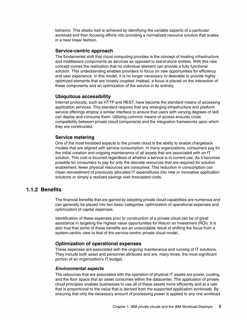
Environmental aspectsThe resources that are associated with the operation of physical IT assets are power, cooling, and the floor space that an asset consumes within the datacenter. The application of private cloud principles enables businesses to use all of these assets more efficiently and at a rate that is proportional to the value that is derived from the supported application workloads. By ensuring that only the necessary amount of processing power is applied to any one workload
Chapter 1. IBM private clouds and the IBM Workload Deployer 5

organizations can eliminate the over allocation of physical resources that is often experienced by application solutions.
Human resourcesIn a traditional application solution, it is necessary to allocate a percentage of the employee’s time to each of the assets that are associated with the solution. With the introduction of cloud computing methodologies, it is feasible to allocate human resources as necessary to support the applications that undergo the most change or integration activities. After the initial configuration and deployment of a new solution occurs, the automated and dynamic nature of the private cloud allows the employee to focus on the next solution or to identify further opportunities for optimization.
Optimization of capital expensesAs is the case with operational expenses, the capital expense allocation in a private cloud computing model can be similarly optimized. Because infrastructure resources are combined into a larger pool, it becomes possible to capitalize on the fact that most workloads operate in a variable manner. The past standard of allocating dedicated hardware resources to a theoretical high water mark is no longer necessary. Additional savings are derived from higher utilization of those hardware assets that are already in use without the need for complex forecasting models, which can be inaccurate. Software licensing is also another critical component to the overall cost of an application solution. Because many suppliers tend to charge on a per-installation basis, a reduction in the number of licenses that are deployed implies a lower total cost of software licensing for any application solution.
1.1.3 Requirements
For any private cloud model to be ultimately successful, it is necessary to ensure a high degree of maturity within its foundational components. Many organizations already invested time into strategies that support these elements and are realizing benefits. Adopting a private cloud can further refine these capabilities and highlight their unique strengths.
VirtualizationTechnologies that abstract the underlying physical resources from the dependent application have existed for many years, and the market solutions reflect this fact. Most organizations have already allocated some portion of their ongoing operations to the development of various virtualization capabilities. Private clouds make heavy use of these capabilities and are reliant upon them to provide some of the dynamic features offered.
InfrastructureMany times referred to as hypervisors, infrastructure virtualization has existed for decades and evolved from a capability provided only by mainframe suppliers. Within the last 10 years solutions were introduced that include services provided by mid- to small-range hardware. Hypervisors permit the abstraction of the traditional hardware services, such as compute, memory, and storage, from the operating systems that make use of them. By allowing this abstraction, it becomes possible to introduce components, experience hardware failures, or upgrade entire solutions without the need for downtime and without impact to the application solution. Recent developments in the areas of storage and networking technologies provide further capabilities for infrastructure virtualization. Dynamic reassignment of network addresses or storage volumes enable this solution to be more resilient and flexible.
PlatformPlatform virtualization encompasses all middleware services, and includes components, such as application servers and databases. This capability is rapidly evolving to meet the
6 Virtualization with IBM Workload Deployer: Designing and Deploying Virtual Systems

requirements of common workloads. The primary differentiation between platform and infrastructure virtualization is the focus on service levels as opposed to availability. Because these solutions exist closer to the consumer, it is appropriate to focus on the user experience rather than the amount of physical resources that are being consumed by an application solution. This unique focus enables the direct association between transactions and the resources that are required to support them with the desired performance characteristics. Another facet of platform virtualization is that individual transactions within an application can now be given prioritization over others. This facet is in stark contrast to infrastructure virtualization, which at best provides prioritization capabilities for an entire application solution.
StandardizationA driving force within any private cloud is the unwavering focus on standardizing elements that comprise an application solution. Organizations are familiar with the concept of using a discrete set of hardware offerings in combination with operating systems that can be best supported and maintained by their IT staff. The opportunities for cost reductions that are associated with such standardization are well known and regularly employed. This simple principle of permitting customization only when required is desirable because it requires fewer highly-skilled resources to both construct and maintain solutions. The next logical evolution of this approach is to focus on the middleware elements that are associated with an application solution. This approach reduces the cost of maintaining the middleware software and configurations and can also have a positive effect on the underlying infrastructure hardware.
AutomationArguably the most critical aspect of any private cloud is the ability to automate both the provisioning and removal of standardized components and resources. It is this capability that makes the dynamic nature of a private cloud a true reality. The ability to construct deployable service units in a repeatable fashion with high levels of consistency simplifies the lifecycle management within a private cloud. Rapid provisioning also enables the on-demand or metering characteristics that are core characteristics for any private cloud.
OptimizationFor any private cloud to be effective in providing the resources required to support current workload demands, it is necessary to continuously review allocations. The automation aspect enables this capability and provides a mechanism to perform this function without human intervention. This process of optimization ultimately permits the scaling up or down of resources to meet the application solution needs and is many times referred to as private cloud elasticity. Inherent to this capability are the concepts of efficient use of hardware and fit for purpose. Optimization allows a much higher normalized or average usage of the physical resources because it provides a level of granularity in resource assignment that cannot be achieved with traditional virtualization techniques alone. It also enables the application solution to examine the characteristics of a particular workload and determine which of the resources available are best suited to achieve an appropriate balance between performance and user experience. An example can be where a singularly threaded batch job is assigned to a hardware resource whose strength is execution of such workloads. Similarly, a highly-parallelized web application can be assigned to processors with multiples cores and pipelines.
1.1.4 Private cloud adoption process
As is the case with many new technologies, private clouds are an evolutionary aggregation of capabilities with which most organizations are familiar. It is important to examine the current maturity of these capabilities to determine which have immediate utility and which require
Chapter 1. IBM private clouds and the IBM Workload Deployer 7

further development to support construction of a private cloud. Over the last several years many IT teams adopted the processes of consolidation and virtualization and maybe even invested in a high degree of process refinement. For those teams, the concepts that are part and parcel to private clouds are not unusual. However, if high degrees of system-level integration or customization are the norm, time must be invested in promoting and understanding the potential benefits that a private cloud can provide.
It is anticipated that most application solutions share common resource requirements and similar expectations for service availability and performance. This is especially true for Internet or web-based applications that are commonly written in the Java programming language and share many of the same architectural characteristics. With the advent of a common programming language that is abstracted from the underlying systems, it becomes possible to aggressively pursue virtualization of the application platforms themselves. This enables the applications to be run on any application platform (hardware, operating system, and application server) that adheres to a standard API. Such a capability is what makes the construction of a private cloud attractive for IT teams. The introduction of application mobility made it possible for organizations to refresh underlying physical hardware, apply system maintenance, or upgrade entire application platforms without incurring outages for the application itself.
Another common characteristic of applications is that load conditions cannot necessarily be predetermined. A single television advertisement or radio commercial can result in a sudden flood of inbound requests to the application. The application solution might not be able to handle the load with the resources at hand. This is especially true for online retailers during peak seasons, such as holiday sales. Similar effects are experienced by many organizations during quarter or year-end batch flows that are associated with annual summaries and reporting. An additional aspect to any application undergoing continuous development is that its workload characteristics will vary over time. Rapid introduction of new features or functions is common and it is not feasible for development teams to stop working while the infrastructure organization determines the resource impact of each change. These situations are also ideal opportunities for the private cloud to address. By prioritizing the importance of particular business transactions it is possible for these organizations to deliver sales or required reporting without purchasing extraordinary levels of resources that will remain unused for the majority of the year.
Figure 1-1 on page 9 depicts the normal cycle of adoption for private clouds. It is common to begin by consolidating workloads onto physical or virtualized hardware in an attempt to better use the available resources. Many times the servers on which applications are housed do not require the full amount of compute or memory resources provided. Recognizing this fact, organizations will attempt to perform a coarse grain collocation of applications within a single physical server or multiple virtual server instances. This can become problematic as workload characteristics and availability aspects vary between the applications. The ultimate solution for this situation is to provide a mechanism for applications to scale above or below the hard resource allocations provided by physical servers or virtual guests. Private clouds provide this capability and can assist an organization in effectively managing the user experience.
8 Virtualization with IBM Workload Deployer: Designing and Deploying Virtual Systems

Figure 1-1 Private cloud adoption cycle
1.2 IBM Workload Deployer
IBM Workload Deployer is one of the foundational elements for the private cloud strategy. This appliance enables the rapid adoption and deployment of both Infrastructure and Platform as Service offerings. It provides a high degree of integration and automation for common scenarios and assists organizations with the adoption and lifecycle management of a private cloud. All of this can be accomplished without investing significant resources into the development of unique skills or advanced process maturity.
Another ideal use case for the IBM Workload Deployer is for rapid prototyping of new business applications. By using this solution, organizations can quickly instantiate a complete application platform and begin testing in a matter of hours. It can return resources to the resource pool in a predetermined time and can also rebuild the platform on demand if further development is desired. This feature enables a change in a common behavior that is to retain a system for excessive periods simply because it takes too long to appropriate the resources initially. Figure 1-2 on page 10 illustrates this unique solution.
IBM Workload Deployer is positioned directly between the business workloads that many organizations use and the underlying infrastructure and platform components. Because of this unique position, IBM Workload Deployer can receive and act upon operational data from the resource pools. It can also monitor application workload demand conditions and adjust resource allocation or prioritization as required to achieve established service level agreements.
IndividualDeployment
Middleware
Application
Hardware
Consolidation & Virtualization
Operating System
Shared Hardware
MW MW
App App
OS OS
SharedHardware
Expected Benefits•Increased utilization of infrastructure•Rapid deployment through standardization & automation
Challenges•Low HW utilization•Heavily customized
VirtualizedApplications
Shared Infrastructure
MW
App
OS
MW
App
OS
MW
App
OS
Chapter 1. IBM private clouds and the IBM Workload Deployer 9

Figure 1-2 IBM Workload Deployer architectural positioning
1.2.1 Features and benefits
IBM Workload Deployer is based on the IBM DataPower® 7199/9005 product family. This appliance offering provides several benefits.
ConsumabilityAfter the initial set up of the appliance and accepting the end user license agreement, the appliance console is immediately available. No extra installation steps are necessary, and you can start building private clouds in minutes.
SecurityIBM Workload Deployer manages a shared, multi-tenant environment, where isolation and security are of utmost importance. The secure nature of the appliance is rooted in a self-disabling switch, triggered if the appliance cover is removed. This physical security allows IBM Workload Deployer to serve as a secure vault for credentials, which can be tied to virtual images throughout their entire lifecycle (in storage, being dispensed, running in the cloud, or being removed from the cloud).
• Policy-driven Workload Management
• Fine-grained Service Level Enforcement
• Workload Optimization• Continuous Availability• Workload and Data Mobility• Governance• Open Standards
InfrastructureMulti-platform Management and Integration
Workloads
API
IBM Workload Deployer
API
WebSphere
Accelerators
System p
System z
x86
Web Apps Batch
AnalyticsBPM
Commerce
10 Virtualization with IBM Workload Deployer: Designing and Deploying Virtual Systems

StorageIBM Workload Deployer contains a storage driver that streamlines the storage of image customizations. When an image is loaded on to the appliance, it is “shredded” into parts by the storage driver. When an image is later customized and re-loaded on to the appliance, it is similarly shredded in a consistent and deterministic way. These collections of shredded images are then compared and only the new or modified ones are stored.
PerformanceIBM Workload Deployer serves as a dedicated store for both the pre-loaded and customized middleware virtual images and patterns. The appliance includes advanced compression and storage techniques that enable a significant number of these sizeable virtual images to be stored by a user. The appliance is backed up by the DataPower processing power that is needed to manage and provision these images to the cloud.
CostThe total cost of ownership (TCO) that is associated with a physical appliance is low. With a single appliance, with single updates, this expensive process is eliminated and requires less skill. Also, the solution is fully tested as one unit, including functionality and performance.
1.2.2 IBM Workload Deployer patterns
One of the core tenets to the flexibility and power of IBM Workload Deployer is the concept of patterns. Patterns are logical descriptions of both the physical and virtual assets that comprise a particular solution. This template-based approach to construction permits the rapid creation and modification of an otherwise complex set of hardware and software components. The use of patterns allows an organization to construct an individual element or integrated solution one time, and then dispense the final product on demand. IBM Workload Deployer provides two types of patterns to assist with the rapid deployment and integration of private cloud capabilities:
� Virtual system patterns provide the most flexibility and customization options of the two types. It consists of an operating system and, potentially, additional IBM software solutions, such as WebSphere® Application Server. These patterns can either be constructed by hand using specialized tools or purchased directly from IBM as an integrated unit.
� Virtual application patterns are highly optimized and are constructed solely for the purpose of supporting a singular workload. The features and functions of the integrated software are limited to only those that are required. This pattern requires the least amount of customization during deployment and it provides the most direct method for obtaining a rapid return on investment.
Figure 1-3 on page 12 provides a high-level view of the pattern types provided with IBM Workload Deployer.
Chapter 1. IBM private clouds and the IBM Workload Deployer 11

Figure 1-3 IBM Workload Deployer pattern types
These patterns represent varying degrees of automation and customization and are optimized with the most appropriate configurations and settings for the solutions that they support. It is conceivable that an organization can deploy and maintain a large portion of their platform services by making use of these patterns alone.
Construction of either Virtual System or Virtual Application patterns is performed by combining one or more elements together, and then performing a degree of integration. The integration activities can be as simple as standardizing the default location for software installation or as complex as in the case of automatic node federation within a WebSphere cell. Figure 1-4 provides a high-level view of the elements that can be used to construct patterns and the characteristics that define them.
Figure 1-4 IBM Workload Deployer pattern elements
Virtual Applications
Custom Hypervisor Edition Images created with ICON
• Delivered as full solutions, tailored for a use case (e.g., "IBM Workload Deployer Pattern for Web Applications")
• Products in workload patterns are subsets of their generally available forms, delivered as an atomic unit
• Optimized-for-purpose, requires no additional scripting or customization
Fle
xib
ility
Lab
or
Savin
gs
• Custom arrangements of Hypervisor Edition virtual images and user scripting
• IBM sells Hypervisor Edition images containing the full functionality of a single IBM product
• IBM Image Construction and Composition Tool (ICON) is available on alphaWorks
Shared Resource ManagementShared Resource Management infrastructure services apply to all workload models:
• User/group permissions management• License management• Usage tracking
Hypervisor Edition Images Offered by IBM
Virtual Systems
Images
• Basic execution services for standalone VM images
• Complete control over image contents
• Basic image management/ library functions
• IBM provided product images
• Ability to create custom images
• Leverages IBM image management tools
Topologies
• IBM defined product images and patterns for common topologies
• Ability to create custom patterns
• Traditional configuration and administration model
• Aligned around existing products
• Automated provisioning of images into patterns
Workloads
• Application awareness
• Fully integrated software stacks
• IBM defined topologies• Simplified interaction model
• Highly standardized and automated
• Integrated middleware with cloud capabilities
• Integrated lifecycle management
12 Virtualization with IBM Workload Deployer: Designing and Deploying Virtual Systems

ImagesThis element is typically associated with a single operating system instance. It provides the core resources of compute, memory, and storage necessary for application execution. An organization can incorporate this element alone into a Virtual System pattern to begin introducing the basic concepts of private cloud computing. Full access to the resulting system is provided, which can be useful in the integration with established operational processes.
TopologiesBuilding upon the previous element, this construct permits an organization to create sets of images for common products. An example is a WebSphere cell consisting of web, application, and database services. The ability to integrate standard aspects of high availability and fault tolerance are contained within this element. Greater emphasis is placed on the platform solutions that are commonly managed by middleware teams.
WorkloadsThe final step in the development and introduction of private cloud capabilities are provided within this element. Significant integration with middleware components and infrastructure resources is achieved and the components are optimized for a particular type of application workload. Very little knowledge of the underlying components is required to deploy and make use of the solution. Dynamic and elastic capabilities are fully realized and the system can create or remove additional resources as required by the application demand.
1.2.3 Customizing
Although sample patterns are provided with IBM Workload Deployer, organizations might find it necessary to introduce additional components or processes to integrate with established systems. This functionality is provided within the solution and assists with the adoption of private cloud capabilities. Each of the pattern categories have varying levels of customization available, and it is conceivable that an organization might desire to begin by reproducing much of their current processes. This can mean construction of entirely new images and integration with the various middleware elements as required. There might also be specific industry or security controls that require unique settings. In either case, the flexibility to construct new patterns from scratch or adapt those provided is contained within IBM Workload Deployer.
A useful way to envision an image is in the concept of an atom. There are many distinct types of atoms, and they all have unique characteristics. However, even atoms of the same element can vary in the number of particles contained within them. This is also the case with images. It might be that the stock images provided by IBM Workload Deployer meet the majority of an organization’s requirements. But it is just as likely that some slight change is necessary to ensure alignment with operational or business processes. By providing the ability to make modifications to the makeup of the image, a powerful level of flexibility is enabled and unique permutations become possible.
Just as with images, topologies are flexible and customizable. And as with the concept of atoms, topologies have an analog in the molecule. Molecules are created by combining atoms of differing types into a construct with unique properties. These molecules cannot be created out of random atoms because there is a particular order and set of prerequisites that must be met for stability. Such is the case with topologies. Although it is possible to place a random set of images together within a logical grouping, it is unlikely that their combination will provide the desired level of utility without some integration between the components. Topologies can be extended to include secondary components or to provide a generalized set of compute resources upon which other services can be deployed. A simple example is in the case of a development environment. It is possible to lock in a standard number or type of
Chapter 1. IBM private clouds and the IBM Workload Deployer 13

servers deployed to meet the basic needs of these activities. After development and testing is complete, another topology that contains aspects of high availability and resiliency can be employed. By using topologies in this manner, an organization can ensure that consistency is achieved in the number and types of resources that are allocated for particular activities.
The strengths of IBM Workload Deployer are truly demonstrated by the manner in which it creates and manages these molecular combinations. It provides the reality of Platform as a Service without introducing a complex set of processes or technologies. Organizations can adjust the Virtual System patterns at a discrete level without creating entirely new images or topologies.
14 Virtualization with IBM Workload Deployer: Designing and Deploying Virtual Systems
Chapter 2. Middleware-centric cloud management with IBM Workload Deployer
This chapter focuses on the customizable and repeatable middleware cloud management features of IBM Workload Deployer, which is the next generation of WebSphere CloudBurst Appliance. It includes all of the capabilities of WebSphere CloudBurst Appliance V2.0 and more.
For those of you who are familiar with WebSphere CloudBurst Appliance, this chapter concentrates on features that are specific to that appliance that are also included in IBM Workload Deployer V3.0. We introduce that technology and then describe the core features and benefits before drilling down into each of its components.
This chapter contains the following topics:
� 2.1, “Technology overview for virtual systems deployment” on page 16� 2.2, “Administrative interfaces” on page 17� 2.3, “Hypervisors” on page 20� 2.4, “IP groups” on page 21� 2.5, “Cloud groups” on page 22� 2.6, “Environment profiles” on page 23� 2.7, “Virtual images” on page 24� 2.8, “Intelligent Management Pack” on page 26� 2.9, “Script packages” on page 27� 2.10, “Virtual system patterns” on page 28� 2.11, “Virtual systems” on page 30� 2.12, “Appliance settings” on page 31� 2.13, “Users and groups” on page 33
2
© Copyright IBM Corp. 2011. All rights reserved. 15

2.1 Technology overview for virtual systems deployment
IBM Workload Deployer is a physical appliance that can provision standard and customized middleware virtual images and patterns that can be securely deployed and managed within private or on-premise cloud computing environments.
These intelligent management solutions use “Hypervisor Edition” virtual images that can help organizations to develop, test, and deploy business applications easily and quickly, thus ending the manual, repetitive, and error prone processes that are often associated with creating these complex environments. Upon completion, resources are returned to the shared resource pool automatically for future use and are logged for internal charge-back purposes. These solutions enable applications to adapt to changing market conditions while lowering costs.
The appliance also manages individual user and group access to resources, providing IT managers with the control needed to optimize efficiency at a fine-grain level. IBM Workload Deployer incorporates management-preferred practices for cost-effective, rapid, and repeatable application deployment in the cloud, and integrates seamlessly with development and service management tools from IBM Rational® and IBM Tivoli® for architectural, design, development, management, and monitoring purposes.
Figure 2-1 shows the three core components of the appliance.
Figure 2-1 IBM Workload Deployer core components
First, you have the physical appliance itself with its hardware configuration and management application firmware, pre-loaded and customizable middleware virtual images, configurable patterns, script packages, and administration interfaces.
Next, you have the on-premise or private cloud environment on which the middleware application runs and which constitutes of the hypervisors, networking infrastructure, and storage devices that are allocated to the appliance.
Finally, you have the virtual systems that are deployed by the physical appliance into this cloud environment. These systems are dispensed into the cloud using the intelligent
Appliance:Hardware configurationAppliance management functionMiddleware virtual imagesPatterns and script packages
Cloud:HypervisorsNetworkingStorage
Virtual systems:Highly customized deploymentDispensed and run in cloudIntelligently managed and monitored
Users andgroups
OVFImages
Patternsand scripts
Web 2.0 UI, CLI, and REST APIs
………..………..………..………..………..………..
………..………..………..………..………..………..
16 Virtualization with IBM Workload Deployer: Designing and Deploying Virtual Systems

placement capabilities of IBM Workload Deployer, which guarantee efficient cloud resource usage coupled with high availability.
To build a custom private cloud with IBM Workload Deployer:
1. Identify the hardware, hypervisors, and networking for the cloud.
2. Select and customize the virtual images.
3. Add script packages to customize the deployed middleware environment.
4. Use preinstalled or customized patterns to describe the middleware topology to be deployed. You can build patterns from virtual images easily using drag-and-drop.
5. Deploy virtual systems to the cloud with the push of a button.
Figure 2-2 shows the various components involved and the flow of operations in building the private cloud.
Figure 2-2 IBM Workload Deployer technology preview
2.2 Administrative interfaces
There are three ways to interact with the IBM Workload Deployer:
� Web-based user interface� Command-line interface� Representational State Transfer REST API
IBM Workload Deployer
Topology PatternVirtual Image
Deploy the images to the cloud
Select and customizethe pattern
Select and customizevirtual images
Add custom scripts
Pre-loaded and customizedvirtual images
Pre-loaded and customizedtopology patterns
Operating System
IBM HTTP Server
WebSphere Application Server
Profiles
Additional Custom Software
Scripts
Script Packages
Customize Security
Define Connections
Install Application
CustomNode
CustomNode
CustomNode
Set up the cloud
Hypervisors
DMgr/IHS
5
1
2
3
4
Chapter 2. Middleware-centric cloud management with IBM Workload Deployer 17

2.2.1 Web-based user interface
The primary administrative access to the IBM Workload Deployer appliance is through the web-based user interface, shown in Figure 2-3. This management console is enabled when the appliance is first initialized through the serial console.
Figure 2-3 IBM Workload Deployer user interface
The Welcome window provides wizards for you to configure the core functionality of IBM Workload Deployer in a step-by-step approach. There are also drop-down menus, highlighted in Figure 2-3, that accomplish the same results in a more granular way. The menu items are grouped by category. For example, the appliance settings are under the Appliance menu item, and the cloud management options for the hypervisors, cloud and IP groups are under Cloud, and so on.
18 Virtualization with IBM Workload Deployer: Designing and Deploying Virtual Systems

2.2.2 Command-line interface
The IBM Workload Deployer command-line interface (CLI) provides a scripting environment based on Jython, the Java-based implementation of Python. In addition to commands that are specific to Workload Deployer, you can issue Python commands at the command prompt. To manage Workload Deployer with the CLI, you can download the command-line tool from the user interface (UI) to a Windows operating system or Linux system, and then point to where Workload Deployer is running, as shown in Figure 2-4.
Figure 2-4 Downloading the command line tool from the UI
Using the Workload Deployer CLI, you can manage a Workload Deployer appliance remotely. The CLI communicates with the Workload Deployer appliance over an HTTPS session. The CLI does not cache updates, and it has only minimal caching for reads.
The Workload Deployer CLI can run in both interactive and batch modes. For interactive mode, use a command similar to the following example, where -h expects the hostname or IP address of the IBM Workload Deployer appliance, -u requires a user name as an argument, and -p specifies the password:
c:\deployer.cli\bin>deployer -h iwd_host -u iwd_user -p iwd_password
The following command returns the list of users defined on the appliance. For batch mode, specify the -c option, followed by the command to execute, as follows:
c:\deployer.cli\bin>deployer -h iwd_host -u iwd_user -p iwd_password -c deployer.users
In addition, if you want the command line to run a given Jython script with a number of arguments, pass in the script name as parameter to the -f flag followed by the arguments:
c:\deployer.cli\bin>deployer -h iwd_host -u iwd_user -p iwd_password -f sample.jy arg1 arg2
For more information about using the CLI, refer to the CLI online help or the Workload Deployer Information Center. The following developerWorks article, although written for WebSphere CloudBurst, is valid to manage the middleware-centric cloud components that we address in this chapter.
http://www.ibm.com/developerworks/websphere/techjournal/0907_burr/0907_burr.html
Chapter 2. Middleware-centric cloud management with IBM Workload Deployer 19

2.2.3 Representational State Transfer REST API
The IBM Workload Deployer appliance exposes a subset of its function using a REST API. Each Workload Deployer appliance exposes a REST API because there are no special configuration settings to enable or disable this interface. The Workload Deployer REST API is available on the same IP address or host name used to access the appliance UI and CLI.
The REST API provides a means to interact with the appliance that is both language neutral and programming model neutral. When using the REST API, you interact with the resources of the appliance, such as the hypervisors, patterns, script packages, and so on, just by using well-defined HTTP URLs and associated HTTP verbs (GET, POST, PUT, DELETE).
Unlike the UI, the REST API is only supported over the HTTPS protocol. The appliance uses a self-signed certificate for its SSL sessions. The same certificate is used for the UI, CLI, and REST API sessions. You must configure your HTTPS client to either accept or ignore this certificate during the SSL handshake. You must use an HTTPS client that allows you to set the HTTP headers for each request.
Finally, the REST API supports only the sending and receiving of UTF-8 encoded data. Ensure that your HTTP client is appropriately set to encode and decode character data, including JSON data.
For additional information about the REST APIs and for examples about how to use them, refer to the IBM Workload Deployer Information Center or the following developerWorks article, which applies to the IBM Workload Deployer although it was written for WebSphere CloudBurst:
Managing your private cloud, Part 2: Using the WebSphere CloudBurst REST API interface:
http://www.ibm.com/developerworks/websphere/techjournal/0911_amrhein/0911_amrhein.html
2.3 Hypervisors
A hypervisor is a software virtualization program that provides a layer of abstraction between operating systems and physical resources on a machine. This abstraction enables multiple operating systems and application stacks to run on a single physical entity, sharing resources, thus enabling higher levels of resource utilization.
To set up the cloud, the administrator defines the location and login credentials for the hypervisors. These hypervisors host the virtual systems that IBM Workload Deployer dispenses. IBM Workload Deployer automatically detects the storage that is associated with the hypervisors and manages the placing of the middleware virtual systems across the set of hypervisors.
At the time of writing, the following hypervisors are supported:
� VMware ESX� IBM PowerVM™� IBM z/VM®
Figure 2-5 on page 21 shows the parameters that can be queried on a given hypervisor on the Workload Deployer appliance. You get to the Hypervisor panel by selecting Cloud Hypervisors from the menu bar.
20 Virtualization with IBM Workload Deployer: Designing and Deploying Virtual Systems

Figure 2-5 Managing hypervisors within IBM Workload Deployer
2.4 IP groups
Another component of the private IBM Workload Deployer cloud is a pool of IP addresses, known as IP groups, that are available for use by the deployed virtual machines. The administrator defines this pool of IP addresses, and when new virtual machines are created, the appliance takes care of assigning each machine a unique value.
Your administrator typically must define the IP group only one time. IP addresses can then be added to and removed from the pre-configured pool as needed.
Figure 2-6 on page 22 illustrates how the pool of IP addresses are managed in the pool on the appliance. You get to this view by selecting Cloud IP Groups from the menu bar.
Chapter 2. Middleware-centric cloud management with IBM Workload Deployer 21

Figure 2-6 IP group management on IBM Workload Deployer
2.5 Cloud groups
A cloud group is a collection of related hypervisors. When deploying patterns to create virtual systems, you use a cloud group as the deployment target. One or more hypervisors of the same type make up a cloud group, for example, you can group all of your ESX hypervisors together or all of your high-end PowerVM hypervisors together.
Select Cloud Cloud Groups on the Workload Deployer appliance to get to the cloud group configuration panel. From there, you can manage resource allocation thresholds, such as CPU or memory usage, and also verify the runtime status of your configured hypervisors, as shown in Figure 2-7 on page 23.
22 Virtualization with IBM Workload Deployer: Designing and Deploying Virtual Systems

Figure 2-7 Cloud group management on IBM Workload Deployer
2.6 Environment profiles
Environment profiles group related deployment configuration, such as virtual machine names, IP address assignment, and cloud groups. Deploying patterns with environment profiles enable deployments across tiers from a single pattern.
In IBM Workload Deployer, environment profiles provide the functionality to:
� Define the operational environments, such as development, test, or quality assurance
� Define virtual machine naming conventions within the operational environment
� Specify whether the IP group or a pattern deployer provides the IP address on the deployment
� Segment the clouds, and IP groups within the clouds, to specific environments
Chapter 2. Middleware-centric cloud management with IBM Workload Deployer 23

� Assign aliases to the cloud resources, such as clouds and IP groups
� Assign sections within the clouds to specific users or groups
With environment profiles, you can also group multiple clouds to be used in the deployment. You can deploy a pattern to multiple cloud groups of the same hypervisor type. You might deploy a pattern to multiple PowerVM cloud groups, for example. However, you cannot deploy a single pattern to a z/VM cloud group and to a PowerVM cloud group. Environment profiles are platform-specific, so IBM Workload Deployer filters out the appropriate clouds.
Figure 2-8 Managing environment profiles on IBM Workload Deployer
2.7 Virtual images
Workload Deployer supports a number of middleware Hypervisor Edition images, in the application infrastructure, business process management, connectivity, database, and portal arena, that are immediately available for use as-is or can be customized to add extra functionality. The appliance uses these virtual images to create and deploy virtual machines into the cloud. The virtual images follow the Open Virtualization format (OVF) specification, which is an industry standard specification for packaging and distributing virtual appliances that contain one or more virtual machines. Using OVF provides a standard mechanism to communicate virtual machine resource requirements to several hypervisors.
Table 2-1 on page 25 lists the current supported Hypervisor Edition image portfolio at the time of writing. This lists is constantly being updated. Use your usual software download channels to acquire them.
24 Virtualization with IBM Workload Deployer: Designing and Deploying Virtual Systems

Table 2-1 Current supported Hypervisor Edition image portfolio
On the appliance, you can manage your virtual images by selecting Catalog Virtual Images, as illustrated in Figure 2-9 on page 26.
Product/Platform RedHatESX
AIX®PowerVM
SUSE zLinuxz/VM
RedHat zLinuxz/VM
SUSE Linux
(64-bit)ESX
SUSE Linux
(32-bit)ESX
WebSphere Portal Server and IBM Web Content Manager V6.5.1
X
WebSphere Portal Server and IBM Web Content Manager V7.0
32-bit X
IBM DB2® V9.7 X X X
WebSphere Process Server V6.2
X X X
WebSphere Process Server V7.0
32-bit X X X
WebSphere Business Monitor V7.0
X
WebSphere MQ V7.0.1
64-bit
WebSphere Message Broker V7.0
64-bit
WebSphere Application Server V6.1
32-bit X X
WebSphere Application Server V7.0
64, 32-bit X X X X X
IBM HTTP Server for WebSphere Application Server V7.0
64, 32-bit X X X X X
Chapter 2. Middleware-centric cloud management with IBM Workload Deployer 25
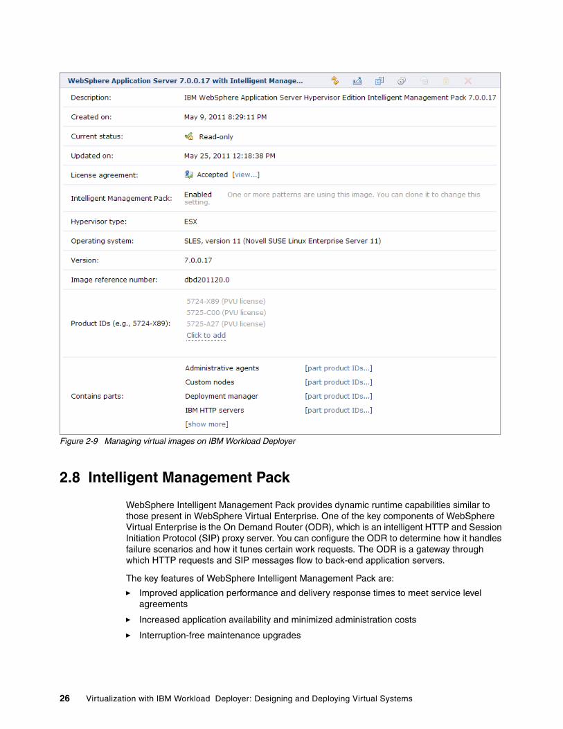
Figure 2-9 Managing virtual images on IBM Workload Deployer
2.8 Intelligent Management Pack
WebSphere Intelligent Management Pack provides dynamic runtime capabilities similar to those present in WebSphere Virtual Enterprise. One of the key components of WebSphere Virtual Enterprise is the On Demand Router (ODR), which is an intelligent HTTP and Session Initiation Protocol (SIP) proxy server. You can configure the ODR to determine how it handles failure scenarios and how it tunes certain work requests. The ODR is a gateway through which HTTP requests and SIP messages flow to back-end application servers.
The key features of WebSphere Intelligent Management Pack are:
� Improved application performance and delivery response times to meet service level agreements
� Increased application availability and minimized administration costs
� Interruption-free maintenance upgrades
26 Virtualization with IBM Workload Deployer: Designing and Deploying Virtual Systems

� Health Management allows you to take a policy driver approach to monitoring your environment and take corrective action when certain predefined criteria are met. Health management standard policies are:
– Monitor when excessive memory is being consumed.
– Monitor when a memory leak has been detected.
– Monitor when a server reaches a certain age and recycle the server automatically.
– Monitor incoming requests and take corrective action if a certain predefined threshold is met (ODR specific).
– Monitor the number of time-out requests and take corrective action if the response times exceed a predefined threshold (ODR specific).
� Dynamic clusters are application deployment targets that operate at the application layer virtualization level taking care of the resources inside the cell. The key points of dynamic clustering are:
– Dynamic clusters grow and shrink depending on the workload demand.
– Dynamic clusters work closely with the ODR to ensure the even distribution of workload amongst the cluster members.
� Overload protection monitors the use of memory and CPU. It regulates the rate at which the on demand router forwards traffic to the application server tier to prevent memory and processor overload.
2.9 Script packages
A script package is an archive (.zip) file that contains artifacts that you want to be executed and artifacts that you want to be executed upon. The code included in the script package can be as simple as a .war file or as complex as a complete product. The content of a script package is not defined by IBM Workload Deployer. The embedded script defines the required content for that package.
During deployment, script packages are transferred to the target virtual machines at a file location you specify in the configuration. After they transfer, they are extracted in that same location. When the virtual machines successfully start and the nodes are federated (if applicable), script packages are then extracted and the scripts are run using the supplied command line. The goal behind using script packages is to further enable you to customize your middleware environment beyond the customization provisions that are standard with Workload Deployer. A typical scenario might be to install a WebSphere Application Server application and configure the required JDBC resources into a server or cluster environment rendered by Workload Deployer.
Figure 2-10 on page 28 shows the content of a sample script package.
Enabling the Intelligent Management Pack feature: The Intelligent Management Pack feature is disabled by default on the WebSphere Application Server Hypervisor Edition image. To enable it, select the Enable option under Intelligent Management Pack, as shown in Figure 2-9 on page 26.
Chapter 2. Middleware-centric cloud management with IBM Workload Deployer 27
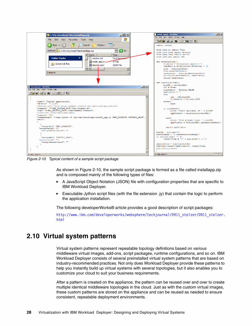
Figure 2-10 Typical content of a sample script package
As shown in Figure 2-10, the sample script package is formed as a file called installapp.zip and is composed mainly of the following types of files:
� A JavaScript Object Notation (JSON) file with configuration properties that are specific to IBM Workload Deployer.
� Executable Jython script files (with the file extension .jy) that contain the logic to perform the application installation.
The following developerWorks® article provides a good description of script packages:
http://www.ibm.com/developerworks/websphere/techjournal/0911_stelzer/0911_stelzer.html
2.10 Virtual system patterns
Virtual system patterns represent repeatable topology definitions based on various middleware virtual images, add-ons, script packages, runtime configurations, and so on. IBM Workload Deployer consists of several preinstalled virtual system patterns that are based on industry-recommended practices. Not only does Workload Deployer provide these patterns to help you instantly build up virtual systems with several topologies, but it also enables you to customize your cloud to suit your business requirements.
After a pattern is created on the appliance, the pattern can be reused over and over to create multiple identical middleware topologies in the cloud. Just as with the custom virtual images, these custom patterns are stored on the appliance and can be reused as needed to ensure consistent, repeatable deployment environments.
28 Virtualization with IBM Workload Deployer: Designing and Deploying Virtual Systems

IBM Workload Deployer comes pre-loaded with a number of virtual system patterns. These patterns were developed based on the IBM experience in the middleware arena for more than a decade. The highlighted section in Figure 2-11 contains those predefined patterns.
Figure 2-11 Pre-defined virtual system patterns on IBM Workload Deployer
Figure 2-12 on page 30 shows a detailed view of one of those virtual system patterns.
Chapter 2. Middleware-centric cloud management with IBM Workload Deployer 29

Figure 2-12 IBM Workload Deployer WebSphere advanced cluster pattern
2.11 Virtual systems
Virtual system instances are created by using patterns that are composed of parts that are provided in your virtual images. The pattern is deployed to your hypervisors based on a component of Workload Deployer called placement. The placement component is an internal component that performs the job of deciding which hypervisors to use when deploying virtual machines. The placement component is also used when an existing virtual system instances is extended by adding virtual machines. It uses an advanced algorithm that considers a number of properties of the environment. For example, it considers the properties of the physical machines, existing virtual system instances on the hypervisors, and virtual machines on the hypervisor not managed by Workload Deployer. The properties of the virtual system instances being deployed or extended are also considered when making placement decisions. Most notably, the placement component considers the memory, physical CPUs, network addresses, disk space, and disk image sharing on the hypervisor. The placement component is part of the product code and is not configurable.
30 Virtualization with IBM Workload Deployer: Designing and Deploying Virtual Systems
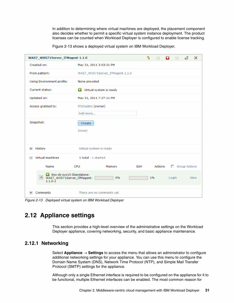
In addition to determining where virtual machines are deployed, the placement component also decides whether to permit a specific virtual system instance deployment. The product licenses can be counted when Workload Deployer is configured to enable license tracking.
Figure 2-13 shows a deployed virtual system on IBM Workload Deployer.
Figure 2-13 Deployed virtual system on IBM Workload Deployer
2.12 Appliance settings
This section provides a high-level overview of the administrative settings on the Workload Deployer appliance, covering networking, security, and basic appliance maintenance.
2.12.1 Networking
Select Appliance Settings to access the menu that allows an administrator to configure additional networking settings for your appliance. You can use this menu to configure the Domain Name System (DNS), Network Time Protocol (NTP), and Simple Mail Transfer Protocol (SMTP) settings for the appliance.
Although only a single Ethernet interface is required to be configured on the appliance for it to be functional, multiple Ethernet interfaces can be enabled. The most common reason for
Chapter 2. Middleware-centric cloud management with IBM Workload Deployer 31

doing so is to add a level of redundancy to your environment. Another reason multiple Ethernet interfaces are used is to enable the appliance to separate the virtual machines network from the administrative one.
2.12.2 Security
Workload Deployer is designed with key features that establish and manage trust across the cloud. In addition to ready for use security on the appliance, you can also use a Lightweight Directory Access Protocol (LDAP) to authenticate users with the Workload Deployer appliance.
Figure 2-14 shows the authentication panel on the Workload Deployer appliance where you can configure the mode of authentication.
Figure 2-14 Authentication panel on IBM Workload Deployer
2.12.3 Appliance maintenance
Using the backup and restore process, you can capture a complete Workload Deployer environment at any point. You can then either restore that environment on the appliance from which it was taken or restore it on another appliance.
Upgrades to the Workload Deployer appliance are done using firmware updates. New firmware versions can be downloaded from the IBM fix central web site and used to update your appliance. A firmware upgrade changes only the appliance application and does not affect the Hypervisor Edition virtual images on the appliance.
Finally, the appliance can be restarted or powered down by selecting Appliance Settings.
For a detailed description of these administrative settings, which also apply to IBM Workload Deployer, refer to WebSphere Cloudburst Appliance and PowerVM, SG24-7806.
32 Virtualization with IBM Workload Deployer: Designing and Deploying Virtual Systems

2.13 Users and groups
Users and user groups are configurable so that you can manage the level of access for each individual to your Workload Deployer appliance.
User permissions are defined to determine which panels are viewable for each user and to determine a user's access to a particular object. Permissions provide the granularity to define the access and roles for each user. Access to patterns, virtual system instances, and catalog content is specified at the object level.
The permissions assigned to users define which administrative tasks for Workload Deployer the users can perform. In addition to determining which of the administrative pages are displayed, the content of the Welcome page is dynamically generated to display distinct content for users that are assigned dissimilar levels of access. For example, the following role-based groups can be defined to control user access to resources on the appliance:
� Pattern deployers: This group has permission to deploy patterns. Typically, these users have less middleware administration expertise and probably want to deploy constructed, configured environments.
� Pattern authors and catalog managers: This group has permission to create patterns, upload script packages, and create custom images. These users are typically seasoned middleware administrators who can build and configure application environments. They simply map their existing configuration knowledge to the various customization approaches in Workload Deployer.
� Cloud and appliance administrators: This group has permission to administer the cloud infrastructure and the appliance. These users are familiar with the configuration and administration of the hardware components within the cloud. In addition, they have the skills necessary to manage and maintain the appliance.
Table 2-2 describes the Workload Deployer panels that are visible on the appliance based on the user permission levels defined.
Table 2-2 Viewable panels based on user permission level
Permission Welcomepage
Instancespage
View Patternspage
View Catalogpage
View Cloudpage
Appliancepage
Deploy patterns in thecloud
Yes Yes Yes Yes No No
Create new patterns
Yes Yes Yes Yes No No
Create new environment profiles
Yes Yes Yes Yes No No
Create new catalog content
Yes Yes Yes Yes No No
Cloud administration
Yes Yes Yes Yes Yes No
Appliance administration (Read only)
Yes Yes Yes Yes No Yes
Chapter 2. Middleware-centric cloud management with IBM Workload Deployer 33

Appliance administration
(Full)Yes Yes Yes Yes Yes Yes
IBM License Metric Tool
Yes Yes Yes Yes No No
Permission Welcomepage
Instancespage
View Patternspage
View Catalogpage
View Cloudpage
Appliancepage
34 Virtualization with IBM Workload Deployer: Designing and Deploying Virtual Systems

Chapter 3. Tooling framework to plan, customize, and automate virtual systems
IBM Workload Deployer provides a solid solution to the creating and managing images to be deployed in a private cloud. It is rich in features that allow you to effectively build and deploy virtual systems from base images, to extend those images, and to customize them for future use as repeatable deployable units. However, there are aspects of building and managing a private cloud solution that can be enhanced using additional products that have specialized features that compliment IBM Workload Deployer.
In this chapter, we discuss how you can use IBM products to enhance the process of building and customizing virtual images and patterns in a private cloud environment and also how to create, plan, and automate the deployment process for repeated delivery.
This chapter contains the following topics:
� 3.1, “Extending the tool set beyond IBM Workload Deployer” on page 36� 3.2, “IBM Image Construction and Composition Tool” on page 37� 3.3, “Rational Software Architect: Deployment planning and automation” on page 37� 3.4, “Rational Automation Framework for WebSphere” on page 41� 3.5, “IBM Tivoli Service Automation Manager” on page 45
3
© Copyright IBM Corp. 2011. All rights reserved. 35

3.1 Extending the tool set beyond IBM Workload Deployer
When development, test, and operations each deploy the same application at different times in the software delivery lifecycle to dispersed environments, the process might be manual, time-consuming, and error-prone because of:
� Little shared understanding of deployment across these groups� No shared automations� No reuse of previous successful cycles, leading to configuration errors
In addition, physical test infrastructure is often time consuming to acquire and configure, expensive to manage and maintain, and under-utilized between tests.
The IBM deployment planning and automation solution, a new approach to application deployment that leverages cloud-based infrastructure to help quickly develop and test new software, can help organizations by:
� Planning your application deployment using discovered resources and standard configuration templates to reduce time and errors and improve communication of deployment requirements and the subsequent automation of provisioning tasks.
� Automating infrastructure provisioning, middleware configuration, and application installation to repeatedly set up standardized environments in the cloud, removing costly manual errors, and dramatically reducing provisioning times.
� Governing and sharing application artifacts, standard templates, deployment plans, and trace development artifacts to deployed instances to support change management.
Figure 3-1 shows a collection of the IBM Rational and Tivoli tools that you can use in conjunction with IBM Workload Deployer in the planning aimed towards building and maintaining highly-customized images and patterns.
Figure 3-1 Tooling for planning, customizing, and automating application deployments
RationalAutomation
Framework forWebSphere
Imagecatalog
ImageImage
Topologycatalog
PatternPattern
Virtualized x86,P, Z, laaS,IBM SBC
Uses
IBM SME orcustomer architect
Creates
Uses Creates
Creates
IBM SME orcustomer architect
IBM development
IBM WorkloadDeployer pattern
builder
Rationalsoftware
Architect DP&A
Imageconstruction
and compositiontool
IBM WorkloadDeployer
Tivoli ServiceAutomation
Manager
IBM SME orcustomer architect
IBM SME orcustomer architect
Uses
Uses
Retrieves
Workloadcatalog
Pattern
Pattern
Rational Application Developer
Uses
36 Virtualization with IBM Workload Deployer: Designing and Deploying Virtual Systems
In Figure 3-1 on page 36:
� IBM Image Construction and Composition Tool (Icon): A tool for building virtual images for deployment into cloud environments. You install the tool as a local virtual machine in your private cloud and then connect it to a cloud to use as a build environment for creating new images. The tool integrates with your existing enterprise resources by connecting to either your private cloud or by utilizing the IBM Smart Business Development and Test on the IBM Cloud, which allows you to take advantage of the servers and storage that you already have and use them as your cloud provider.
� Rational Software Architect (RSA) Deployment Planning and Automation (DP&A): Allows you to plan and validate deployment of applications and infrastructure and generate and publish workflows to drive automation and the creation of service templates.
� Rational Automation Framework for WebSphere (RAFW): Provides a framework for you to work from the published deployment workflow from RSA, typically managed by Rational Asset Manager (RAM), refine it as required, and save it as an asset. The Rational Automation Framework automation engine then performs automation activities to configure the middleware and deploy the application in the private cloud.
� Tivoli Service Automation Manager (TSAM): Provides you with the capability to request, deploy, manage, and monitor cloud services from a single management interface. Regardless of which type of cloud service or software components constitute the service, you can use TSAM to standardize and automate the delivery of the environment to your cloud. After it is delivered, TSAM builds on existing IT infrastructure to provide insight into the full lifecycle of the cloud-based service.
� IBM Workload Deployer Pattern Builder: The built-in pattern builder in IBM Workload Deployer, as discussed in Chapter 2, that allows you to create topology/virtual system patterns based on virtual image parts, script packages, and custom configuration settings.
� Rational Application Developer: The integrated development environment on which an application developer can build an application, access a workload application pattern created by the IBM SME or customer solution architect, and then publish it to the catalog for future deployment to the private cloud.
3.2 IBM Image Construction and Composition Tool
You can use the IBM Image Construction and Composition Tool to build virtual images for use in a cloud environment. Images built using the Image Construction and Composition Tool can be provisioned to the cloud using WebSphere CloudBurst Appliance, IBM Workload Deployer, Tivoli Provisioning Manager, or the IBM Smart Business Development and Test on the IBM Cloud. Additional support for images created with IBM Image Construction and Composition Tool is introduced with IBM Workload Deployer V3.1.
3.3 Rational Software Architect: Deployment planning and automation
IBM Rational Software Architect (RSA) with an extension for Deployment Planning and Automation (DP&A) provides a graphical environment on which to define the target topology and to plan activities to configure the machines within it and the middleware running on them. It helps bridge the Development-Operations communication gap with semantically rich topology templates and deployment models to ensure that your software solutions deploy correctly on the first attempt.
Chapter 3. Tooling framework to plan, customize, and automate virtual systems 37
This extension can be used with IBM Rational Software Architect to provide the following core benefits:
� Smarter IT Deployment Planning: Communicate and validate IT deployments to avoid costly problems late in the application lifecycle
� Deployment Template Design and Reuse: Capture and reuse organizational standards to quickly and easily plan deployments
� Datacenter Discovery: Quickly construct a topology describing what you have in your infrastructure
The focus of deployment planning and automation is to address the complex problem of deploying IT applications across heterogeneous environments. It is about solving the problem where operations inherits an application from development from an environment totally foreign to them with hardly any idea about the infrastructure it must run on. A considerable amount of time and effort is spent trying to generate automation scripts, which are typically rarely reused, and struggling through impossible to debug issues. This is generally the result of the lack of communication that exists between the separate organizations.
What RSA delivers is the ability for application architects to define the deployment plans or topology of the infrastructure that the application must run on. This way they can determine the servers, JDBC data sources, JMS providers, deployment node configuration, and so on of the target environment at the beginning of the process and pass the information to the operations group.
Figure 3-2 on page 39 shows how solution architects can make use of environment configurations, templates, and artifacts to specify deployment plans from a set of reusable building blocks in RSA so that a proven environment can be stored and reused over and over throughout the product lifecycle across the organization.
38 Virtualization with IBM Workload Deployer: Designing and Deploying Virtual Systems

Figure 3-2 Rational Software Architect: Deployment Planning and Automation
Figure 3-3 on page 41 shows a typical scenario that identifies the deployment planning and automation flows with RSA and the other products that it interacts with to address the challenges we discussed earlier. We do not cover the automation phase in this section because we cover that in detail when we introduce Rational Automation Framework for WebSphere (RAFW) in 3.4, “Rational Automation Framework for WebSphere” on page 41.
During the deployment planning phase, a solution architect uses RSA with the extension for Deployment Planning to plan the deployment of their composite application (with an application topology) generally using a logical reference architecture for the target environment. Application topologies allow the user to specify the application components, their dependencies, deployment requirements, and how they are hosted against a target reference architecture that is captured as a template topology, stored, and governed using Rational Asset Manager (RAM). The rich technical semantics, diagramatic capabilities, and validation support make the deployment planning tools an effective communication device
Chapter 3. Tooling framework to plan, customize, and automate virtual systems 39

between development and operations. The application topology can then be published in RAM to be governed and handed over to the Deployment Engineer to create the corresponding automation workflow.
While creating a deployment plan, the architect might utilize live infrastructure data by connecting and querying discovered resources from Tivoli Application Dependency Discovery Manager (TADDM) and standard technical templates and application artifacts that are stored and governed in RAM. Using standardized templates that the operation team creates removes costly manual and error prone configuration steps when creating deployment plans because the templates capture the technical details of the chosen technologies. After it is created, the deployment plan can be published to RAM to be approved and governed.
The deployment engineer is then responsible for using RSA to bind the application topology from the solution architect to the target environment, which is accomplished by creating a deployment topology and importing the application topology and selecting the target environment. The target environment can be described as a template in RAM, or it can be discovered using an integration with the TADDM. The deployment engineer binds conceptual structures, such as servers, clusters, and so on, from the imported application topology to elements from the target environment. Because the constraints and requirements from the application topology are enforced on the bound element in the target environment, the deployment engineer cannot make target environment binding selections that conflict with the constraints that the solution architect defined. It is possible for the deployment engineer to bind the application topology to multiple target environments as necessary.
After a bound deployment topology is created, the deployment engineer can plan the automation workflows for provisioning the application. The engineer uses RSA with the extension for Deployment Planning and Automation and RAFW to automatically generate an automation workflow from the deployment topology. The automatic generation of the workflow works by analyzing the deployment topology detecting registered patterns that are associated with deployment tasks. The engineer can modify and adjust the workflow prior to publishing it to RAFW for execution. With the built-in integration for Build Forge® and RAFW, the engineer can publish the automation workflow and RAFW configuration files from RSA to automatically construct the executable automation project in Build Forge and configure the RAFW environment tree. Publishing the workflow from RSA to Build Forge/RAFW dramatically reduces or eliminates manual steps to define the executable automation project and matching RAFW environment.
As a final note, there is an RSA and Tivoli Service Automation Manager (TSAM), introduced in 3.5, “IBM Tivoli Service Automation Manager” on page 45, integration package that is available on the Integrated Service Management (ISM) Library. This integration package makes it possible to create a Service Definition Archive from RSA and a corresponding importer within TSAM that allows the deployment engineer to quickly and easily import a new service definition into the service catalog with a management plan (for example, provision workflow). It automatically defines the flow to provision the target environment and configures the RAF integration module to call the generated RAF project. As a result, it removes more manual configuration steps, allowing less-skilled users to construct and automate services using standard building blocks in RSA.
40 Virtualization with IBM Workload Deployer: Designing and Deploying Virtual Systems

Figure 3-3 Rational Software Architect Deployment Planning and Automation integration
3.4 Rational Automation Framework for WebSphere
Rational Automation Framework for WebSphere simplifies the configuration and administration of WebSphere deployments by providing built-in functions for several common tasks. It provides a centralized interface that allows users to automate the import of WebSphere installations, perform routine maintenance, such as patching or fix pack installation, and deploy applications with their associated configuration files to target environments. This solution permits administrators and developers alike to attain a greater level of confidence in platform configuration and life cycle management than is available when using more traditional methodologies. Additional capabilities include:
� Scheduling projects for unattended configuration or installation of software� Enables baseline comparison of the changes made throughout the platform lifecycle� Integrated auditing for association with change or modification activities� Trigger-based notification to alert on project status or system messages� Role-based security mechanism for enablement of separation of duties
Figure 3-4 on page 42 depicts the architecture of Rational Automation Framework for WebSphere and some components with which it can interact. This solution is accessible using both rich and thin clients and provides integration with other services using both agent and agentless communication protocols. Because Rational Automation Framework for WebSphere is based on standard Internet protocols and programming interfaces, it is easy to extend without having to learn a unique set of proprietary programming routines.
Rational SoftwareArchitect
Applicationartifacts andtemplates
Deploymentplan
Retrieveapprovedapplicationartifacts
•Deployment Planning- Pre-deployment validation, improving accuracy- Reusing standard configurations helping avoid
costly mistakes
Install and configureapplication
Seamlessworkflow
ServiceRequester
Request service
•Deployment AutomationAccelerating repeatable infrastructure and software deployment through seamless workflow management
Cloud
Solution Architect
Deployment Engineer
RationalAsset
Manager
IBMWorkloadDeployer
RationalAutomationFramework
Chapter 3. Tooling framework to plan, customize, and automate virtual systems 41

Figure 3-4 Rational Automation Framework for WebSphere architectural overview
The main components that are used to construct an automated routine in Rational Automation Framework for WebSphere are:
� Environment: A logical collection of variables. For the purposes of this book, these variables describe WebSphere deployments, including cells, clusters, nodes, and servers.
� Action: A script that performs the actual automation functions within the project steps. Rational Automation Framework for WebSphere enables the construction of composite or super-composite actions through a combination of multiple standard actions.
� Project: The actual automation plan that is created using actions and applied to environments or servers within an environment.
After a project is created, it can be run in several unrelated modes that affect the behavior of the project steps. The three operational modes that we use in our scenario are preview, import, and execute. In preview mode, the project’s steps are invoked in a “dry-run” manner with tracing enabled. This allows for basic debugging operations and validation that the project steps execute as expected. Import mode is used when reading the configuration of an existing WebSphere cell. Execute mode invokes the actual project to apply a configuration change or otherwise modify the associated environment.
3.4.1 Integration with IBM Workload Deployer
The ability to update the Rational Automation Framework for WebSphere environment and configuration repositories when deploying a new pattern from IBM Workload Deployer is
RAFW
DeploymentManager
ServerServer
ServerServer
SourceControlMgmt
DeploymentManager
ServerServer
ServerServer
DeploymentManager
ServerServer
ServerServer
RationalAsset
Manager
Agent
Agent
AgentDatabase
Application ServerCustomAdmin
Web Browser
Web Browser
Web Browser
Rich Client
Existinginvestment incustom adminis preserved
• Centralized automation server
• Proven enterprise automation platform
42 Virtualization with IBM Workload Deployer: Designing and Deploying Virtual Systems

important because it ensures an additional level of continuity in the management and administration of a private cloud. The integration mechanism that is provided enables a common process to capture the baseline configuration of an application platform. Along with this baseline, an environment and associated project is generated that can be duplicated or modified as needed. This environment can assist with the process of configuration checkpoints or to deploy the same application to a dissimilar platform topology.
Figure 3-5 illustrates the interaction between Rational Automation Framework for WebSphere and IBM Workload Deployer when deploying a pattern that includes the integration script package.
Figure 3-5 Rational Automation Framework for WebSphere integration script process flow
3.4.2 Integration use case options with IBM Workload Deployer
For the purposes of this book, Rational Automation Framework for WebSphere is used to perform the activities in this section.
Cell capture and environment importThe initial deployment of a pattern within the private cloud can be further automated using the Rational Automation Framework for WebSphere integration script package. This script package enables a hands-free generation of both the Environment and Project that will be used for platform configuration management. The project itself can be run in both import and execute Modes that have the effects of either gathering all current configurations or re-deploying previously captured settings. These initial artifacts represent a description of the deployed cell that can be used to restore the environment to its initial configuration. The project will be further augmented and customized for deployment in a production-like topology to generate the concept of promotion.
Both initial environment creation and a full configuration import are performed for the purposes of this publication. After the solution topology is deployed, a representative environment will be generated automatically that describes the basic components of the infrastructure. This enables Rational Automation Framework for WebSphere to ascertain
IBM Workload Deployer
Rational Automation Framework for WebSphere
WebSphere Cell
IHS
DMGR
WAS WAS
1
2
3
Pattern containing the RAFW integration script is deployed1
Deployment manager performs call back to generate environment2
RAFW connects to each component and imports/applies configuration3
Chapter 3. Tooling framework to plan, customize, and automate virtual systems 43

which systems to connect to so that additional configuration information can be gathered. After the initial environment generation completes, a full import of the WebSphere cell will be performed to capture custom settings, such as JDBC providers or WVE configuration.
Configuration promotionThe concept of configuration promotion is one that appeals to many organizations. It is not uncommon for a middleware administrator to install and configure the necessary software components by hand. This manual configuration introduces a number of error conditions that are multiplied for every subsequent installation. Construction of a second environment in this manner amplifies these potential errors. By the time configuration of development, test, and production systems is complete, a number of differences can arise. The differences can affect either the stability or performance of the platform solution and weaken both the reliability and availability of the systems involved. Using the capability of configuration promotion makes it possible to ensure that platform configuration settings that must remain constant do so.
For the purposes of this publication, we use the configuration promotion capability to migrate platform and application configurations from a pre-production environment to a production environment.
Application deploymentInstalling application code (EAR or WAR file) within the Java Virtual Machine is a core capability of Rational Automation Framework for WebSphere that we demonstrate in the example scenario of this book. Using a project-based approach to application deployment ensures consistency in the process. It also permits the delegation of application deployment activities to non-administrative users. Full auditing and error handling is provided, including a notification mechanism for project status.
Fix pack installationOne of the standard operational functions of any organization is the application of patches or software maintenance. Like many of the common administrative activities, this capability is also provided within the base functionality. Using this software installation capability allows an organization to reduce the amount of time required to perform routine maintenance. This frees resources that are otherwise dedicated to these activities to focus on operational effectiveness. Installing a fix pack is demonstrated as part of the example scenario within this book.
The level of integration with IBM Workload Deployer varies with each of these activities and demonstrates a subset of the full capabilities that are available.
Manually configuring WebSphere with automated reconfigurationIn this scenario, the systems themselves are created using IBM Workload Deployer. The WebSphere environment is manually configured with applications deployed and tuned for performance and reliability. You want to have a copy of this configuration to reduce the time involved with recreating the environment. Rational Automation Framework for WebSphere can be used to perform a full import of the settings and all related artifacts. After these tasks are captured, it is possible to apply the configuration directly to similar environments and promote the configuration through Test, Pre-production, and production systems. Each time IBM Workload Deployer creates the environment, it can call Rational Automation Framework for WebSphere to apply the tuned configuration and deploy the applications.
Creating patterns for existing environmentsThis scenario is similar to the prior scenario except that the installations of WebSphere are created without using the IBM Workload Deployer or Rational Automation Framework for
44 Virtualization with IBM Workload Deployer: Designing and Deploying Virtual Systems
WebSphere solutions. These heritage implementations present a unique challenge because documentation that describes each component and its unique configuration might not be available. By using Rational Automation Framework for WebSphere it is possible to not only capture these heritage configurations, but create a topology pattern that can be used to document and describe the environment. In the case of a catastrophic failure, this topology description can be used to assist with rebuilding the infrastructure components. The platform configuration can then be applied directly to restore the environment to a known good state.
Physical to virtual platform migrationThe concept of infrastructure virtualization is well-known within most organizations. Unfortunately, it is often difficult to provide the level of assurance necessary when migrating WebSphere environments from physical to virtual servers using traditional means. The result is that applications continue to remain on server hardware that might be out of warranty or is more powerful than required to achieve the necessary performance. By simultaneously using the rapid provisioning capabilities of IBM Workload Deployer and the environment configuration strengths of Rational Automation Framework for WebSphere, you can provide a level of surety during the migration. This ability enables a rapid transition from existing or overpriced physical assets into a dynamic infrastructure that can be managed with fewer resources and higher levels of availability.
Rapid prototyping for innovationWith the advent of application development methodologies, such as Agile, it is increasingly important for organizations to provide ready access to platform solutions, which helps to ensure continuity in the development life cycle. In some cases, developers might even want to create multiple variants of a single application platform solution. By having this capability available, an organization can enable rapid prototyping of new application features. Additional benefits include reductions in the overhead associated with scheduling platform resources and the occasional wide-impact outages inherent to any shared testing solution. In this situation, IBM Workload Deployer can be used to rapidly provision the platform and Rational Automation Framework for WebSphere can perform the necessary personalization. Both of these activities can be done automatically in a matter of minutes or hours instead of the days or weeks associated with manual construction. The end result is a dynamic development platform that can be instantiated or decommissioned at will and according to the established application development time lines.
3.5 IBM Tivoli Service Automation Manager
IBM Tivoli Service Automation Manager (TSAM) enables users to request, deploy, monitor and manage cloud computing services. This Tivoli offering enables a modern and dynamic data center framework made up of the following components:
� Self-Service Portal: Enables data center personnel to achieve rapid time-to-value for virtual-server provisioning from any platform
� Service catalog: Standardized images and environments are automatically updated, and an outstanding user experience through the self serve portal
� Automated Provisioning: Ability to set up new environments and capable of de-provisioning resource and return to pool
� Image Library: Provides a framework for maintaining multiple repositories of server images for use during virtual server provisioning
Chapter 3. Tooling framework to plan, customize, and automate virtual systems 45

For system administrators and planners looking to build a private cloud computing environment, TSAM and IBM Workload Deployer provide a number of benefits when deployed within the same environment:
� IBM Workload Deployer allows users to create, deploy, and manage customized middleware application environments in a private cloud. The patterns-based approach taken by the appliance allows rapid, consistent provisioning of those application environments.
� TSAM equips users with the necessary tools to drive high degrees of standardization and automation in their cloud environment, hence enabling rapid provisioning for a wide range of workloads. In addition, TSAM provides an integrated management and monitoring platform that helps decrease operating costs for your private cloud.
� The integration of the two products means that users benefit from a wide spectrum of service delivery and management capability provided by TSAM, while still inheriting the depth of middleware capability provided by IBM Workload Deployer. The integrated solution provides a unified interface through TSAM from which users can deploy and manage all of their cloud-based environments.
IBM Workload Deployer exposes its patterns as service offerings in the TSAM service console with TSAM being the top-level management device for your private cloud. This way, TSAM exposes both patterns from the given IBM Workload Deployer appliance and service offerings defined in its own catalog from within a single management portal. Similarly, the user can benefit from the value of IBM Workload Deployer and its patterns through its rapid provisioning, consistent configurations, and inherent product knowledge for middleware-based workloads without having to switch back and forth between multiple service management portals.
Figure 3-6 on page 47 provides an illustration of the integration of the two products. When you request an IBM Workload Deployer pattern deployment through the TSAM portal, the latter communicates with the appliance to drive the deployment of the requested pattern from the appliance's repository to the private cloud.
46 Virtualization with IBM Workload Deployer: Designing and Deploying Virtual Systems

Figure 3-6 Integrating Tivoli Service Automation Manager and IBM Workload Deployer
There are a few things to take into consideration when integrating the two products:
� TSAM interacts with IBM Workload Deployer through a well-defined interface. Any IBM Workload Deployer capability exposed by TSAM derives from its usage of the appliance's REST APIs. In this way, the coupling is loose and inter-product dependencies are limited to publicly documented and supported interfaces. Additionally, this means that IBM Workload Deployer behaves as it would if you were to use it directly, meaning, among other things, that you still benefit from the appliance's intelligent placement algorithm for virtual systems.
� TSAM enables other solutions to be integrated. TSAM is a prominent part of other IBM cloud offerings including IBM CloudBurst and IBM Service Delivery Manager. Because of that, you can integrate IBM Workload Deployer and IBM CloudBurst, and IBM Workload Deployer and IBM Service Delivery Manager, in the same way that you integrate it with TSAM.
� TSAM exposes a subset of IBM Workload Deployer capability in its management portal. From the TSAM interface, you can request a deployment of an IBM Workload Deployer pattern and remove the virtual system when you want. You still interact directly with the appliance to define your private cloud, creating custom images and patterns, manage resource access, and more.
� All TSAM and IBM Workload Deployer capabilities remain the same. When integrating them, the integration in no way restricts the capabilities of either of the products. Rather,
IBM WorkloadDeployer
Tivoli ServiceAutomation Manager
Patterns
Chapter 3. Tooling framework to plan, customize, and automate virtual systems 47

the integration sets the stage for you to take a unified approach to managing a cloud consisting of heterogeneous services.
In general, knowing when to integrate TSAM and IBM Workload Deployer is about identifying situations where one offering can provide complementary value to the other. While it is impossible to list every possible scenario, we can identify a couple of common integration scenarios based on user needs:
� When there is a need for unified management of private clouds that include middleware products
� When you must add request workflow capabilities to IBM Workload Deployer
For a close-up look on how to set up the integration between the two products, refer to the following article (written for WebSphere CloudBurst Appliance but still applicable to IBM Workload Deployer):
Build a private cloud with CloudBurst and TSAM
http://www.ibm.com/developerworks/cloud/library/cl-cloudbursttsam/
48 Virtualization with IBM Workload Deployer: Designing and Deploying Virtual Systems

Part 2 The ITSO private cloud sample
In this part, we show how to create a private cloud using IBM Workload Deployer and other related products. In particular, we use Rational Automation Framework for WebSphere to automate the configuration of our environment and IBM Tivoli Monitoring as the enterprise monitoring infrastructure. We also use the Intelligent Management Pack and WebSphere eXtreme Scale to provide a dynamic and scalable infrastructure to our application.
This part contains the following chapters:
� Chapter 4, “Sample overview” on page 51
� Chapter 5, “Configuring the IBM Workload Deployer” on page 71
� Chapter 6, “Creating and customizing virtual images” on page 107
� Chapter 7, “Creating the pattern and environment profiles” on page 139
� Chapter 8, “Configuring the pre-production system” on page 159
� Chapter 9, “Capturing the pre-production configuration and applying it to a production deployment” on page 211
Part 2
© Copyright IBM Corp. 2011. All rights reserved. 49

50 Virtualization with IBM Workload Deployer: Designing and Deploying Virtual Systems

Chapter 4. Sample overview
In this chapter, we describe the sample application and the ITSO private cloud used to illustrate the actions that are required to build a custom cloud environment. Using a private cloud approach allows us to overcome the limitations of a classic infrastructure and provide more flexibility to the system.
We describe the application and the requirements that it must satisfy.
This chapter contains the following topics:
� 4.1, “Application requirements” on page 52� 4.2, “The ITSO private cloud” on page 57� 4.3, “Customizing the components” on page 66� 4.4, “Deploying the virtual system” on page 69
4
© Copyright IBM Corp. 2011. All rights reserved. 51

4.1 Application requirements
Our application is a simple servlet that runs in WebSphere Application Server V7. This servlet stores HTTP session data. We will create an environment to run this application that takes the following requirements into consideration:
� HTTP session management
The HTTP session data must be stored to provide failover capabilities and to maintain the session state.
� Dynamic scaling capability based on the workload and service level agreement (SLA)
The runtime resources must be optimized so that we can use the same systems for additional applications. An SLA will also be in place with the users of the application that spells out the performance and availability requirements. The infrastructure must have the resources required to meet the SLA.
� Disciplined environments to run the application
To successfully deploy an application into a production environment, different crucial aspects have to be considered. One of this key aspects is to have a set of separate stages to develop, test, and deploy the application.
� Application life cycle and configuration management:
Our system has to provide automated feature to manage the life cycle of our application from one stage to anther (in our sample, we show only pre-production and production, but this can be extended to as many stages as you need). We want to have automated features to consistently promote the configuration to the next steps, avoiding manual activities.
� Enterprise monitoring infrastructure
Our system is based on a private cloud implementation. A cloud-based implementation aims to offer ease of scale, quality-of-service, resource optimization, and other characteristics across a dynamic and virtualized environment.
Monitoring cloud services is a key to determine if you are obtaining all of those advantages and in which degree. It is also crucial to have visibility on the cloud. This means respond faster with better decisions based on the performance of the environment monitored.
4.1.1 HTTP session management with WebSphere eXtreme Scale
HTTP session management is a functionality offered by the Java Enterprise Edition (JEE) application servers. WebSphere Application Server offers two options to store HTTP sessions:
� Persist HTTP session on a database� Memory-to-memory HTTP session replication
While these mechanisms are comparable from a performance point of view they each have their challenges and associated costs.
Replicating session in memory means that you are using part of the JVM heap size to store HTTP session replicas from other servers. Moreover you have a limited amount of sessions that you can store that are based on the total amount of memory that your JVMs have. If you want to add more memory, you must add another JVM, which means worse efficiency in resource utilization. If your application only needs N-1 JVMs to run, you add another JVM just for HTTP session (storing) purposes, which lowers the JVM utilization.
52 Virtualization with IBM Workload Deployer: Designing and Deploying Virtual Systems

Storing session data in a database requires that you manage a database (and probably you will depend on database administrators for this). Moreover database do not easily scale, and might became a performance bottleneck.
Both of these mechanisms also have limits that suggest you should not share sessions between data centers.
A third option for HTTP session management is available with the addition of WebSphere eXtreme Scale to your environment. WebSphere eXtreme Scale provides the ability to build an in-memory data grid that can be run on hundreds of servers. It can be configured to process, replicate, and manage application data across servers and data centers.
WebSphere eXtreme Scale can be used in multiple scenarios, including application state store (or HTTP session store), which will be the case in our scenario. Using WebSphere eXtreme Scale for HTTP sessions does not require any application changes, but is a simple matter of building a grid for the cached session data and configuring WebSphere Application server to use the grid for this application. Only sessions that use cookies as the session tracking mechanism can be saved to the data grid. You cannot persist sessions that use URL rewriting as a session tracking mechanism.
Note that WebSphere eXtreme Scale is a software product. Another option is the WebSphere DataPower XC10 appliance. The appliance offers support for a subset of the WebSphere eXtreme Scale usage scenarios, including application state store.
4.1.2 Dynamic scaling with WebSphere Virtual Enterprise
An important consideration for workload and service level agreement (SLA) management is the efficient utilization of application serving resources. In a classic JEE environment, an application is installed in a JEE-compliant application server. If the application requires high availability, it is installed in a cluster, which is a collection of application servers with the same configuration that serve the application. WebSphere Application Server supports static clusters, where you manually specify the application servers that are members of the cluster.
In static clusters, you must size the cluster based on the peak usage expected for the application or applications that are installed in the cluster. This action can lead to a poor resource utilization because the workload typically peaks only during specific times during the day. The rest of the time, your system is under-utilized. If an application experiences a higher peak usage than expected, you cannot easily apply more resources to that application, even if you have free resources available.
A second consideration for workload and SLA management in a classic JEE environment, is providing resources during times of constraint to the more critical applications. All the applications installed in your JEE system are considered to be equal, that is, there is no way to define that one application is more important than another. So if application A and application B are installed on the same subset of resources and both of them are under peak usage, both of them suffer because of resource constraints. Unfortunately, in the real world some applications are more important than others.
WebSphere Virtual Enterprise offers functionality that can help solve the issues of efficient resource utilization and workload management. It offers the ability to define a dynamic cluster, which is a cluster that can grow or shrink based on the load on the application served. It also offers the ability to define relative priorities for your applications. In the event of a resource constraint, this prioritization allows the infrastructure to remove resources from the application with the lower priority to give more resources to the important application. With
Chapter 4. Sample overview 53

these abilities, you have greater control over resource utilization and can hypothetically consolidate more applications on a lower hardware capacity.
Starting with WebSphere Application Server Hypervisor Edition 7.0.0.11, WebSphere Virtual Enterprise is available in the virtual images enabled for the Intelligent Management Pack. The features include all of the functionalities that WebSphere Virtual Enterprise offers with a degree of integration with IBM Workload Deployer.
4.1.3 Virtual system life cycle management with IBM Workload Deployer
To successfully deploy an application to your production environment, you must test the application in the runtime environment. It is important that you have well-defined and separate deployment stages as you prepare for production deployment. These deployment stages can include development, test, quality assurance, performance, research, pre-production, and production. Note that these stages are examples and will vary with the needs of your company.
In our scenario, we show the pre-production and the production stage to illustrate the concepts in this book. We decided to focus on these two stages because while they are ideally as similar as possible, it is not uncommon to have an application work perfectly in the pre-production environment but encounter problems in the production environment. We focus on reducing the risk of problems with the adoption of a configuration promotion strategy. We also discuss how to optimize the resources and to have as many stages as possible even when facing resource constraints.
IBM Workload Deployer offers the ability to store a virtual system that is deployed for future use. Using this feature you can use the same hardware to run your application at various life cycle stages. IBM Workload Deployer manages the virtual system life cycle management, as shown in Figure 4-1 on page 55.
54 Virtualization with IBM Workload Deployer: Designing and Deploying Virtual Systems

Figure 4-1 Resources life cycle management with IBM Workload Deployer
In Figure 4-1:
1. Dispense a pattern to the cloud as a virtual system.
2. Run the virtual system as long as you need it.
3. Remove the resource reservation by deleting or storing the virtual system. Storing a virtual system releases the hardware resources but not the IP addresses.
4. Delete the virtual system to return all the resources to the resource pools.
If you store the virtual system rather than delete it, you can rapidly restart it in the future. However, because IBM Workload Deployer offers rapid systems provisioning you can also delete the system and deploy it again quickly, if needed.
4.1.4 Application life cycle management with Rational Automation Framework for WebSphere and script packages
The life cycle of an application typically involves multiple stages. Managing the life cycle of the application while moving the application and the configuration needed to run it at each stage is error prone if done manually.
In our scenario, we want our system to be as automated as possible to avoid redundancy and to ensure consistency in the deployment and the configuration process. Automation not only allows for speed of deployment but allows repeatability and consistency in the environment creation. Automation also allows a reduction in the number of inconsistencies when moving an application through its various life cycle stages.
Returncapacity to
available pool
Dispense singlevirtual imageor a pattern
At the end ofthe reservation,
remove the virtualimage(s) from
the cloud
Virtual ApplicationsHypervisor Edition Images
Custom Configurations
Run in virtual /cloud computing
environment(IaaS)
1
2
3
4
Chapter 4. Sample overview 55

The concept of configuration promotion, meaning the capacity to move configurations from one stage to anther in a consistent manner, is one that appeals to many organizations. It is not uncommon for a middleware administrator to install and configure each of the necessary software components manually. Error conditions introduced during this process are multiplied for every subsequent installation. Construction of a second different environment in this manner can amplify these errors. The results can affect the stability or performance of the platform solution and weaken both the reliability and availability of the systems involved.
Using a configuration promotion capability makes it possible to ensure that platform configuration settings that must remain constant do so. There are two separate approaches to accomplish this:
� Create your own scripting libraries. WebSphere Application Server offers scripting support through Jython. Every configuration step can be executed through a Jython script. You can use Jython to create your own scripts for automating the configuration of your environment. This unfortunately also means that you must maintain those scripts.
� Use script libraries provided and maintained by someone else. Rational Automation framework for WebSphere is a tool that offers hundreds of pre-built scripts that can be used to customize your WebSphere Application Server environment. IBM maintains those scripts.
For the purpose of our sample, we use both of these approaches. We use script packages and Rational Automation Framework for WebSphere.
Rational Automation Framework for WebSphereRational Automation Framework for WebSphere offers a variety of functionality. We are specifically interested in using the following capabilities to create our environment:
� Cell capture and environment import
Rational Automation Framework for WebSphere can be used to capture the configuration of an existing cell and import it into a virtual system in IBM Workload Deployer. Both an initial environment creation and a full configuration import are performed in our scenario.
After our topology is deployed, a representative environment is generated automatically that describes the basic components of the infrastructure. This enables Rational Automation Framework for WebSphere to ascertain which systems to connect to so that additional configuration information can be gathered.
After the initial environment generation completes, a full import of the WebSphere cell is performed to capture custom settings, such as JDBC providers and the WebSphere Virtual Enterprise configuration.
� Configuration promotion
In our scenario, the configuration promotion capability is used to migrate platform and application configurations from a pre-production environment to a production environment.
� Application deployment
Installation of application code to (EAR or WAR file) within the JVM is a core capability of Rational Automation Framework for WebSphere and is demonstrated in our scenario. Using a project-based approach to application deployment ensures consistency in the process and permits the delegation of application deployment activities to non-administrative users. Full auditing and error handling is provided, including a notification mechanism for project status.
� Fix pack installation
The installation of a fix pack using Rational Automation Framework for WebSphere is demonstrated as part of the scenario.
56 Virtualization with IBM Workload Deployer: Designing and Deploying Virtual Systems

Script packagesSome of the steps needed to set up our environment in an automated style cannot be performed using Rational Automation Framework for WebSphere. Using IBM Workload Deployer you can add script packages to its catalog. These scripts can be used to automatically execute scripts when a system is created. We use script packages to perform the following actions:
� Augment the profiles to add the functionalities offered by WebSphere eXtreme Scale� Configure the IBM Tivoli Monitoring agent for base OS
4.1.5 Enterprise infrastructure monitoring with IBM Tivoli Monitoring
IT departments typically face many challenges. The most important is the ability to pro-actively identify issues that can affect the performance and availability of the applications and the application serving environments. The adoption of a cloud approach leads to a more dynamic environment where the concept of resource reuse and optimization is a key of this kind of approach.
The adoption of an enterprise monitoring solution then becomes important. It allows us to monitor and manage distributed resources through a centralized console. To determine if we are getting the most from our environment, we must have an enterprise monitoring infrastructure to keep track of all the changes that happen in a dynamic infrastructure. Our choice for the monitoring infrastructure is the IBM Tivoli Monitoring. This platform provides real-time monitoring and management of the systems deployed in our cloud, capabilities to monitor specific conditions that occur in the system, reporting, and raising alerts.
4.2 The ITSO private cloud
In the previous section, we described the requirements of our system. We also introduced some of the components that we use in our implementation:
� IBM Workload Deployer� The cloud (the hardware resources managed by IBM Workload Deployer)� WebSphere eXtreme Scale� WebSphere Virtual Enterprise (the Intelligent Management Pack)� Rational Automation Framework for WebSphere� IBM Tivoli Monitoring
Figure 4-2 on page 58 shows a high-level overview of our cloud. This implementation satisfies the following characteristics, described in 1.1, “Private clouds” on page 4:
� Pools of resources� Dynamic and elastic� Service-centric approach� Ubiquitous accessibility
Chapter 4. Sample overview 57

Figure 4-2 High level overview of our private cloud implementation
IBM Workload Deployer offers cloud shaping and topology management functionalities. It provides the ability to enable a self-service middleware-based cloud (service-centric approach).
Operators are allowed to create and deploy middleware in a platform-as-a-service based on virtual images or virtual applications. In our scenario, we use the IBM Workload Deployer to define and deploy virtual image systems. The IBM Workload Deployer console is Web based, allowing an ubiquitous access through a browser.
WebSphere eXtreme Scale and WebSphere Virtual Enterprise give us the ability to create a scalable, dynamic, elastic, and optimized system. WebSphere eXtreme Scale can be used to store HTTP sessions, offering scalability and reliability features. It can be used to separate the conversational state data from the application layer. These two layers can then scale independently. If you need more computational power, you can simply add a new application layer component, as shown in Figure 4-3 on page 59.
Cloud Shaping andTopology Management
WebSphereVirtual
Enterprise
DynamicInfrastructure
Services
IBM Workload Deployer
IBM WorkloadDeployer Pattern
Application
Optimized with WebSphere eXtreme Scale
Tivoli Monitoring
Automate configuration andapplication lifecycle
management
Rational AutomationFramework for
WebSphere
Monitor
58 Virtualization with IBM Workload Deployer: Designing and Deploying Virtual Systems
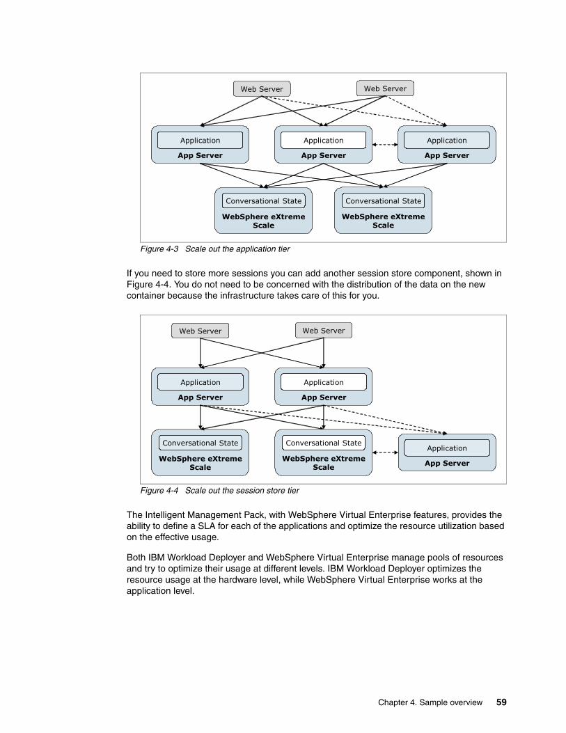
Figure 4-3 Scale out the application tier
If you need to store more sessions you can add another session store component, shown in Figure 4-4. You do not need to be concerned with the distribution of the data on the new container because the infrastructure takes care of this for you.
Figure 4-4 Scale out the session store tier
The Intelligent Management Pack, with WebSphere Virtual Enterprise features, provides the ability to define a SLA for each of the applications and optimize the resource utilization based on the effective usage.
Both IBM Workload Deployer and WebSphere Virtual Enterprise manage pools of resources and try to optimize their usage at different levels. IBM Workload Deployer optimizes the resource usage at the hardware level, while WebSphere Virtual Enterprise works at the application level.
App Server
Web Server
Application
App Server
Application
WebSphere eXtremeScale
WebSphere eXtremeScale
Conversational State
App Server
Application
Web Server
Conversational State
App Server
Web Server
Application
App Server
Application
WebSphere eXtremeScale
Conversational State
App Server
Application
Web Server
WebSphere eXtremeScale
Conversational State
Chapter 4. Sample overview 59

4.2.1 Virtual system topology
To meet the requirements of our application, we defined a simple topology based on the following components:
� A deployment manager for the WebSphere Application Server cell
� An HTTP server
� An WebSphere Virtual Enterprise On Demand Router (ODR)
� Four WebSphere Application Server custom nodes
The custom nodes are used to create two clusters:
� A dynamic cluster using WebSphere Virtual Enterprise. This cluster runs our sample application. These custom nodes must have the WebSphere eXtreme Scale client installed.
� A cluster to run the remote data grid. This cluster stores HTTP sessions using WebSphere eXtreme Scale.
Figure 4-5 shows the topology.
Figure 4-5 Least complex topology design
In this topology, user requests enter the HTTP server in the DMZ. The requests are then forwarded to the ODR, which acts as an HTTP proxy, sending requests to the application running in the dynamic cluster. The ODR can prioritize inbound traffic according to service
Cell
HTTPServer
WXS Client
Application
WXS Client
Application WVEDynamic Cluster
WASDMGR
Grid Grid
Partition
WASWXS
Cluster
CatalogServer
CatalogServer
WXSStandalone
Catalog Service Domain
ODR
60 Virtualization with IBM Workload Deployer: Designing and Deploying Virtual Systems

policy configuration. It manages traffic flow to the application servers in the dynamic cluster to ensure that the load is balanced and that servers are not overloaded. When a request arrives at the application, a session object is created. The application server is configured to use the WebSphere eXtreme Scale grid to cache the session data. The WebSphere eXtreme Scale catalog servers control the placement of the session data in the grid.
The purpose of this topology is to demonstrate how you can build a custom pattern with the IBM Workload Deployer. It is not the purpose of this book to describe how to create a production topology. For instance, we only use one HTTP server and one ODR. In a production topology, you most likely configure these components for high availability by having more than one instance of each. Information you need to effectively design a dynamic cluster topology and WebSphere eXtreme Scale is not included in this book.
4.2.2 WebSphere eXtreme Scale topology
In our scenario, we use WebSphere eXtreme Scale to store session data. In this type of use, the WebSphere Application Server installation that hosts the application collecting and using the session data becomes the client of the grid holding the data. The grid is a collection of WebSphere eXtreme Scale server components that act in concert to manage the data stored in the grid.
This section takes you through the high-level concepts and topology options that were used to design our scenario topology.
Grid topology conceptsTo design the WebSphere eXtreme Scale topology, there are a few basic concepts to understand. We provide a high-level view of those concepts here, but if you are not familiar with WebSphere eXtreme Scale, this information is not enough to design and build a grid. Additional resources on this topic are in “Related publications” on page 341.
WebSphere eXtreme Scale consists of two primary process types: a catalog service and the containers that host the grid:
� Catalog service processes
The catalog service hosts the logic needed to support and manage hundreds of containers. A catalog service is not involved in the normal grid operation when a steady state is reached. It offers the following services:
– Location service: Used by a client that intends to connect to the grid. The client contacts the catalog service to retrieve a routing table describing which containers host the data. The location service is also used by a container that starts and wants to register itself as a container.
– Placement service: Defines the distribution of the data across the available containers.
– Core group manager: Organizes the containers into small groups that monitor the availability of each of the group’s members through a heartbeat mechanism. One of the group members is responsible for sending failure information to the catalog service.
– Administration: Offers the ability to manage and monitor the grid.
The catalog service is made up of a single catalog server or of multiple catalog servers in a catalog service domain. Catalog service domains define a group of catalog servers that manage the placement of the data in the grid and monitors the health of container servers. The use of multiple catalog servers is highly recommended to provide high availability for the services offered.
Chapter 4. Sample overview 61

You can also choose whether to have the catalog services running within a WebSphere process or run in a stand alone JVM.
� Container server processes:
The container servers are the processes that actually store the application data. The data is generally split into partitions. Each partition has one primary copy of the data and one or more replicas, hosted by several JVMs. The collection of containers forms the grid.
Figure 4-6 Basic WebSphere eXtreme Scale components
Grid topology optionsWhen determining the topology for the container servers, there are two basic possibilities for placement of the servers:
� Embedded grid configuration
In this configuration, the eXtreme Scale grid is located in the same application server as the application. Compared to memory-to-memory replication, this scenario offers a better replication and invalidation mechanism, but you still have session data co-located with the application, which can result in a non-optimized resource utilization. For this topology, you must install WebSphere eXtreme Scale to your application server environment.
� Remote grid configuration
In this configuration, the eXtreme Scale grid is remote to the application and located on dedicated JVMs. These JVMs can be a WebSphere Application Server JVM or a stand alone JVM.
A remote grid physically separates the conversational state layer from the application layer and can be useful when you must deal with large HTTP session objects because you can scale the conversational state layer independently. WebSphere eXtreme Scale is memory intensive, but does not require powerful CPUs. In a remote grid topology, you can consider running the grid on less expensive, less powerful hardware while saving the more powerful CPUs for your application.
Catalog service
Core groupmanager Admin
Placementservice
Locationservice
Container 1 Container 2
Partition 1Primaryshard
Replicashard
Partition NReplicashard
Primaryshard
62 Virtualization with IBM Workload Deployer: Designing and Deploying Virtual Systems

In a remote grid configuration, you only need to install the WebSphere eXtreme Scale client on your application server environment where the application runs. The WebSphere eXtreme Scale client and server code is installed on the systems where the grid will run.
Client configurationThe application that requires session management is installed in a WebSphere Application Server environment. The WebSphere eXtreme Scale client code is installed on the systems running the application. The installation of the client adds new functionality to WebSphere Application Server that allows you to configure HTTP session persistence using WebSphere eXtreme Scale. This configuration can be performed using the WebSphere Application Server administrative console, as shown in Figure 4-7.
Figure 4-7 Configure WebSphere Application Server to use WebSphere eXtreme Scale to store sessions
ITSO grid topologyFigure 4-8 on page 64 shows the topology for our scenario. The application that will use the grid for session management will run in WebSphere Application Server. The nodes where the application runs have the WebSphere eXtreme Scale client installed. The grid runs remote from the application. The catalog service and grid are placed on the same systems, but while the grid container servers run on WebSphere Application Server, the catalog servers run in stand alone JVMs.
Chapter 4. Sample overview 63
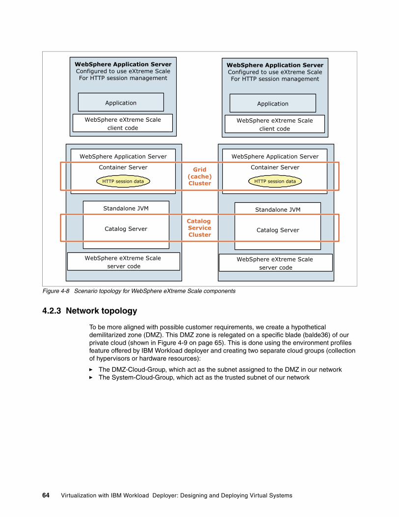
Figure 4-8 Scenario topology for WebSphere eXtreme Scale components
4.2.3 Network topology
To be more aligned with possible customer requirements, we create a hypothetical demilitarized zone (DMZ). This DMZ zone is relegated on a specific blade (balde36) of our private cloud (shown in Figure 4-9 on page 65). This is done using the environment profiles feature offered by IBM Workload deployer and creating two separate cloud groups (collection of hypervisors or hardware resources):
� The DMZ-Cloud-Group, which act as the subnet assigned to the DMZ in our network� The System-Cloud-Group, which act as the trusted subnet of our network
Standalone JVM
Catalog Server
WebSphere Application Server
Container Server
WebSphere eXtreme Scale server code
Standalone JVM
Catalog Server
WebSphere Application Server
Container Server
WebSphere eXtreme Scale server code
WebSphere Application ServerConfigured to use eXtreme ScaleFor HTTP session management
Application
WebSphere eXtreme Scaleclient code
WebSphere Application ServerConfigured to use eXtreme ScaleFor HTTP session management
Application
WebSphere eXtreme Scaleclient code
Catalog ServiceCluster
Grid(cache)Cluster HTTP session dataHTTP session data
64 Virtualization with IBM Workload Deployer: Designing and Deploying Virtual Systems

Figure 4-9 Cloud network topology
This is used only for the purpose to show how to customize the deployment of a virtual system. We use the environment profiles to be able to specify the IP addresses. The environment profiles allow you to decide whether or not to delegate to IBM Workload Deployer the assignment of the IP addresses to the virtual images deployed, as shown in Figure 4-10. This is just a higher level of control that you can optionally use; otherwise, you can deploy the system on a cloud group and have IBM Workload Deployer to manage the IP addresses assignment.
Figure 4-10 Define who has to assign IBP addresses
Using environment profiles at deploymentUsing environment profiles allows you manage conditions specific to an environment at deployment time, for example, the WebSphere eXtreme Scale grid does not need a lot of computational power, but needs memory to store data. You can use the environment profiles to deploy the grid’s servers on less powerful machines, while the cluster running the application can be deployed on more powerful machines. This feature can also be useful from a licensing perspective, allowing you to save processors value units.
We use environment profiles in our sample to control the cloud group used at deploy time and to allow the deployer to select the IP addresses of the new systems versus having them taken
DMZ-Cloud-GroupBlade36
System-Cloud-Groupblade9,
blade40, and blade45
FIREW
ALL
FIREW
ALL
Chapter 4. Sample overview 65

from an IP group. Environment profiles are created and used in Chapter 7, “Creating the pattern and environment profiles” on page 139.
4.2.4 Pre-production and production virtual systems
In our sample, we are going to create two separate virtual systems based on the topology in Figure 4-5 on page 60: a pre-production (ITSO pre-production system) and a production (ITSO production system) virtual system.
These two virtual systems illustrate the promotion of the application and of the configuration from one stage to the other. Rational Automation Framework for WebSphere is the tool we use for this demonstration. These two systems are also used to demonstrate the functionalities of all the components used. Of course it is possible to extend this scenario to a higher number of stages and applications.
In Chapter 7, “Creating the pattern and environment profiles” on page 139, we show how to rapidly provision a virtual system with IBM Workload Deployer. This virtual system, the ITSO pre-production system, has only a few basic customizations: the IBM Tivoli Monitoring agent configuration and the profile augmentation for WebSphere eXtreme Scale. In Chapter 8, “Configuring the pre-production system” on page 159, we show how to configure this system to run our sample application. These steps are typical when a virtual system for a new application is created:
1. Deploy the new system environment (manually or with some degree of automation).
2. Configure the deployed system (manually or with some degree of automation) and test the configuration.
3. If everything works, promote this configuration to the next stage using one of the following methods:
– Recreate the new system in the same way as the previous system– Automate the promotion with automation scripts or frameworks– Use a combination
Using an automated solution, either with scripts or a framework, allows us to save time and reduce the errors in the creation. In particular, we might need to deploy the same virtual system multiple times. If the time saved with the first deployment is not worth the time spent to automate, consider what you save if you need to deploy the same system a third, fourth, fifth time, and so on. The time saved and the errors avoided (and the time spent in troubleshooting, which can be significant) are now much more significant.
After we have a stable configuration, we capture it using Rational Automation Framework for WebSphere. The usage of the integration scripts offered by the Rational framework allows us to deploy the ITSO production system in a fully automated way.
4.3 Customizing the components
The topology defined in Figure 4-5 on page 60 is defined in a IBM Workload Deployer through the creation of a virtual system pattern and deployed on the resources managed by the appliance. By default, the Hypervisor Edition images provided by IBM do not provide all the functionalities that are needed to set up our environment. Some degrees of customization are indeed required. The steps required for this customization are described in detail in Chapter 6, “Creating and customizing virtual images” on page 107. This section is intended to provide you with an overview of the customization process.
66 Virtualization with IBM Workload Deployer: Designing and Deploying Virtual Systems

4.3.1 The basic component: The Hypervisor Edition image
WebSphere Application Server Hypervisor Edition is the basic building block for our system. By default, this product includes the WebSphere Application Server binaries, the HTTP binaries, and some default profiles used by the activation engine to create the desired WebSphere profile at deployment time.
WebSphere Application Server Hypervisor Edition also includes the WebSphere Virtual Enterprise functionality using the Intelligent Management Pack.
4.3.2 Customizing the base image
For the purposes of this example, we need additional components to be installed on this system. The components we need to install are:
� IBM Tivoli Monitoring agent for Linux OS v6.2.2� WebSphere eXtreme Scale v7.1 client on two custom nodes� WebSphere eXtreme Scale v7.1 server on two custom nodes
This customization requires the extension of the basic image. From a technical point-of-view, we can modify a single image and install the IBM Tivoli Monitoring agent and WebSphere eXtreme Scale. That image can then be used to create all of the components that we need. From a licensing point-of-view, creating a single image with the full WebSphere eXtreme Scale product impacts all of the images with the licensing cost of those components. For this reason we decided to extend two separate images:
� WAS7_WXS71Client_ITMagent
This image has the Intelligent Management Pack enabled, the IBM Tivoli Monitoring agent installed, and the WebSphere eXtreme Scale client, which is free of charge. This image can be used for the HTTP server, the ODR, and the two custom nodes running the application.
� WAS7_WXS71Server_ITMagent
This image has the Intelligent Management Pack disabled, the IBM Tivoli Monitoring agent installed, and the WebSphere eXtreme Scale server. This image can be used for the two nodes running the grid.
We are still missing one component: the deployment manager. The deployment manager, for management purposes, must have both the Intelligent Management Pack enabled and the WebSphere eXtreme Scale server installed. Instead of extending another image, we can simply clone the WAS7_WXS71Server_ITMagent image and enable the Intelligent Management Pack.
Figure 4-11 on page 68 shows the our topology with the component just listed.
Activation engine: The activation engine is basically a bundle of scripts and libraries that allow you to automatically configure the Hypervisor Edition image at startup.
Chapter 4. Sample overview 67

Figure 4-11 Topology with the software components used
We are not configuring the IBM Tivoli agent and we are not augmenting any WebSphere Application Server profiles at this time. These processes are done at deployment time using script packages.
Now we have all the components needed to create our topology.
4.3.3 Creating and customizing the pattern
To deploy our systems, we must create a representation of the topology. This representation is a new pattern in IBM Workload Deployer. Figure 4-12 on page 69 shows our base pattern: the version number associated to each part reflects the three images we defined in 4.3.2, “Customizing the base image” on page 67:
� 1.1.1 is the image with the Intelligent Management Pack enabled, the WebSphere eXtreme Scale server, and the ITM agent
� 1.1.0 is the image with the Intelligent Management Pack disabled, the WebSphere eXtreme Scale server, and the ITM agent
� 1.0.0 is the image with the Intelligent Management Pack enabled, the WebSphere eXtreme Scale client, and the ITM agent
Cell
HTTPServer
ITM Agent
WXS Client
IMP
Application
WXSClient
WXSServer
ITM Agent
WXSServer
ITM Agent
ITM Agent
IMP
Application
WXSClient
ITM Agent
IMP
DMGR
WXSServer
ITM Agent
FIREWALL
FIREWALL
DMZ
ODR
68 Virtualization with IBM Workload Deployer: Designing and Deploying Virtual Systems

You can see in Figure 4-12 that the IBM HTTP server has a different version because we decided not to monitor this part because it is not really needed to prove our scenario. In the event that you want to monitor the HTTP server too, you must add the agent to this image.
Figure 4-12 Pattern definition
This is the basic pattern definition. Deploying this pattern requires the following additional steps:
� Augment the custom node profiles and the deployment manager profile with the WebSphere eXtreme Scale functionalities.
� Configure the ITM agent to effectively communicate with the server.
We automate these steps with a script package. Script packages are discussed in 2.9, “Script packages” on page 27, and an example can be found in 6.1, “Uploading the script packages” on page 108.
4.4 Deploying the virtual system
After a pattern is defined, including script packages for customization that occurs at deployment, we can start to deploy our systems. We must differentiate between the pre-production environment and the production environment. Our pre-production deployment still requires some manual configuration steps, but, as you will see, all of the future deployments based on that configuration are fully automated.
Deploying the pre-production systemWe deploy the pre-production pattern and provide some configuration both manually and using Rational Automation Framework for WebSphere. Basically, we deploy the pattern with IBM Workload Deployer. This pattern has the IBM Tivoli Monitoring configuration script included. After the system is ready, we log in to the WebSphere Application Server console and execute manual configuration actions (create the dynamic cluster definition, the grid cluster definition, and define the catalog service’s cluster). Using the command assistance, we log all the manual configuration steps for future reuse in Rational Automation Framework for WebSphere to automate each of the next deployment. Then we capture the configuration
Chapter 4. Sample overview 69

using Rational Automation Framework for WebSphere to use for all new deployments of the same pattern.
Deploying the production systemBy cloning the pre-production pattern, we define the production pattern. We must add to this pattern the Rational Automation Framework for WebSphere’s integration scripts. This allows us to call Rational Automation Framework for WebSphere from the virtual system deployed and have all the configuration steps automatically executed.
70 Virtualization with IBM Workload Deployer: Designing and Deploying Virtual Systems

Chapter 5. Configuring the IBM Workload Deployer
In this chapter, we illustrate the steps needed to set up the appliance to create our private cloud. When you log in to the appliance with an administrative user, the welcome panel provides links to the steps that are needed to configure the appliance:
� Set up the appliance� Set up the cloud� Add virtual images� Set up pattern types
In this chapter, we describe the first three steps. The last step is described in Chapter 7, “Creating the pattern and environment profiles” on page 139.
This chapter contains the following topics:
� 5.1, “Logging into the appliance user interface” on page 72� 5.2, “Setting up the appliance” on page 73� 5.3, “Setting up the cloud” on page 84� 5.4, “Adding a new virtual image” on page 100
5
Before you begin: To complete the scenario described in this book, we assume that you have set up the appliance and completed the steps described in the IBM Workload Deployer information center:
http://publib.boulder.ibm.com/infocenter/worlodep/v3r0m0/index.jsp?topic=/com.ibm.worlodep.doc/gs/gst_setupdev.html
© Copyright IBM Corp. 2011. All rights reserved. 71

5.1 Logging into the appliance user interface
The configuration of the appliance is done with the user interface.
1. Open a web browser, and enter the URL of the user interface:
https://9.42.170.220/login
2. Log into the IBM Workload Deployer user interface as an appliance administrator, as shown in Figure 5-1. We use cbadmin, the default administrative user that comes with the appliance.
Figure 5-1 IBM Workload Deployer login panel
3. When you first log into the IBM Workload Deployer with an administrator user ID, the Welcome panel is displayed, as shown in Figure 5-2 on page 73. The panel has four expandable sections. The section we are dealing with initially is the “Setting up your private cloud section”. Expand this section if it is not already expanded.
72 Virtualization with IBM Workload Deployer: Designing and Deploying Virtual Systems

Figure 5-2 IBM Workload Deployer Welcome window
5.2 Setting up the appliance
For the purpose of our scenario, we defined the following roles. We assigned distinct permissions to these roles to have an effective assignment of duty to the users who belong to those groups.
� The ITSOadms role is the ITSO administrator user group. Users who are assigned to this group can extend images and add script packages to the catalog. Only users of this group can add content to the catalog. ITSOadms users provide the ITSOopts users all the basic components that they need to create a new topology. The ITSOadms users can also lock some options of the basic virtual images. An example is to lock the operating system root password because we do not want ITSOopts users to know this password.
Chapter 5. Configuring the IBM Workload Deployer 73

� The ITSOopts role is the ITSO operator user group. This group is the WebSphere administrator group. Users from this group can define topologies and environment profiles. Users from this group can also install additional software during the extension process of a virtual images.
� The ITSOdeps role is the ITSO deployer user group. The users who are assigned to this group have only the basic permission to deploy a system on the cloud.
5.2.1 Creating the user IDs
In this step, we define the following user IDs:
� ITSOadm1� ITSOopt1� ITSOdep1
These user IDs are created with basic permissions. In a later step, we add these users to user groups, and they inherit the permissions from their group.
To define the ITSOadm1 user, follow these steps:
1. In the user interface, select Appliance Users, as shown in Figure 5-3.
Figure 5-3 Appliance menu
2. A list of users for the appliance is displayed. You should see at least one user-defined Administrator. The Administrator user represents the cbadmin user ID. The green symbol ( ) next to the user ID means that the user is or was logged in earlier.
To create a new user, click New ( ), as shown in Figure 5-4.
Figure 5-4 Add a new user
74 Virtualization with IBM Workload Deployer: Designing and Deploying Virtual Systems

3. In the dialog box that opens, enter the required information for the ITSOadm1 user, as shown in Figure 5-5, and click OK.
Figure 5-5 Define user ITSOadm1
Chapter 5. Configuring the IBM Workload Deployer 75

4. The new user ID is added to the list, and a configuration page is displayed, shown in Figure 5-6. You do not need to provide any additional permissions. The user is added to a user group later and will inherit the group permissions.
Figure 5-6 User defined and default permission
5. Repeat steps 2 to 4 for the ITSOopt1 and ITSOdep1 users. When complete, the list of users should look like Figure 5-7.
Figure 5-7 The list of users defined
76 Virtualization with IBM Workload Deployer: Designing and Deploying Virtual Systems

5.2.2 Creating the user groups
Next, define the user groups:
1. In the user interface, select Appliance User Groups.
2. The group Everyone is provided by default. Click New ( ), as shown in Figure 5-8.
Figure 5-8 Add a new user group
3. In the dialog box that opens, Figure 5-9, enter ITSOadms as the group’s name, and add a description. Click OK.
Figure 5-9 Define ITSOadms user group
Chapter 5. Configuring the IBM Workload Deployer 77

4. The new group is added to the list, and a configuration page will open. Give this group the full set of permissions by checking each box in the Permissions section and selecting Full permissions in the Cloud administration and Appliance administration sections. This configuration is shown in Figure 5-10.
You do not need to save your changes because they are automatically saved.
Figure 5-10 Providing full permission to ITSOadms user group
5. Add the ITSOadm1 user to the ITSOadms group. Click in the Group members field and the list of users is displayed, as shown in Figure 5-11. Select ITSOadm1.
Figure 5-11 Add user ITSOadm1 to group ITSOadms
The result should look like Figure 5-12.
Figure 5-12 ITSOadm1 now is in the Group members field
78 Virtualization with IBM Workload Deployer: Designing and Deploying Virtual Systems

Note that the Group member field now lists ITSOadm1.
6. Repeat steps 2 through 5 to define the ITSOopts group, but select only the following permissions, as shown in Figure 5-13:
– Deploy patterns in the cloud– Create new patterns– Create new environment profiles
Figure 5-13 Provide create new pattern permission to ITSOopts
Add the ITSOopt1 user to the ITSOopts group, as shown in Figure 5-14.
Figure 5-14 Add user ITSOopt1 to group ITSOopts
7. Repeat steps 2 through 5 to define the ITSOdeps group, but this time define only the default permission as shown in Figure 5-15 on page 80:
– Deploy patterns in the cloud.
Chapter 5. Configuring the IBM Workload Deployer 79

Figure 5-15 Provide basics permission to ITSOdeps
8. Add the ITSOdep1 user to the ITSOdeps group, as shown in Figure 5-16.
Figure 5-16 Add user ITSOdep1 to group ITSOdeps
9. The resulting list of user groups in the navigation column on the left should now look like Figure 5-17.
Figure 5-17 User groups listed
We created all the users and user groups that are needed.
80 Virtualization with IBM Workload Deployer: Designing and Deploying Virtual Systems

5.2.3 Reviewing users’ permissions
We provided specific permissions to the user groups based on the roles we defined. This section discusses the differences between the permissions granted.
To review users’ permissions:
1. Log out from the console, and log in as the ITSOadm1 user. The console will show the user ID you are logged in with, as shown in Figure 5-18.
Figure 5-18 Log in as ITSOadm
The options you see in the console menu are an indication of the permissions for this user ID. Because ITSOadm1 is in the ITSOadms group, and that group was given all permissions, this user ID is allowed to do everything:
a. Go to Appliance Users, and select the ITSOadm1 user. Look at the user’s permissions, and notice that the ITSOadm1 inherited the permissions from the ITSOadms user group, shown in Figure 5-19 on page 82.
Using LDAP for authentication: You can add as many users as you want to the user groups. IBM Workload Deployer allows you to use a Lightweight Directory Access Protocol (LDAP) directory to authenticate users within the appliance. Note that this directory server can be used only to authenticate, not to authorize, users and user groups.
You can find further details about how to configure a directory server in IBM Workload Deployer at:
http://publib.boulder.ibm.com/infocenter/worlodep/v3r0m0/index.jsp?topic=/com.ibm.worlodep.doc/welcome.html
Chapter 5. Configuring the IBM Workload Deployer 81

Figure 5-19 ITSOadm1 permissions
You cannot change any of the permissions that are granted to the user because these permissions are defined at the user group level. If you define a user but do not assign the user to a group, the user by default is assigned to the Everyone user group. This group has permission only to deploy a pattern in the cloud.
b. Open the Cloud menu, and note that ITSOadm1 is allowed to access IP Groups, Cloud Groups, Hypervisors, and all the entities listed in the menu, as shown in Figure 5-20.
Figure 5-20 ITSOadm1 option list in the Cloud menu
2. Log out from the console, and log in as the ITSOopt1 user, as shown in Figure 5-21 on page 83:
a. If you compare Figure 5-18 on page 81 with Figure 5-21 on page 83, you can see that the ITSOopt1 user has a different list of items in the menu on the console. This user does not have the Reports and Appliance options.
82 Virtualization with IBM Workload Deployer: Designing and Deploying Virtual Systems

Figure 5-21 Console menu for ITSOopt1
b. If you open the Cloud option, Environment Profiles is the only option available. Select Cloud Environment Profiles. Note that ITSOopt1 can create new environment profiles (the New icon ( ) is available, as shown in Figure 5-22).
Figure 5-22 ITSOopt1 can create an Environment Profiles
3. Log out from the console, and log in as the ITSOdep1:
a. Notice that the first level menu items are the same as for ITSOopt1. The difference is in the 2nd level menus.
b. Select Cloud Environment Profiles from the menu, and you will see that the ITSOdep1 user cannot create environment profiles. The New icon ( ) is not available.
Chapter 5. Configuring the IBM Workload Deployer 83
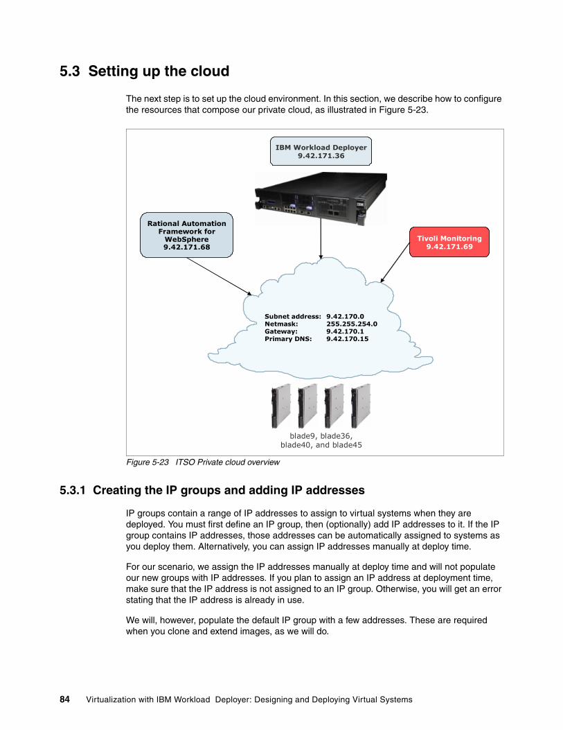
5.3 Setting up the cloud
The next step is to set up the cloud environment. In this section, we describe how to configure the resources that compose our private cloud, as illustrated in Figure 5-23.
Figure 5-23 ITSO Private cloud overview
5.3.1 Creating the IP groups and adding IP addresses
IP groups contain a range of IP addresses to assign to virtual systems when they are deployed. You must first define an IP group, then (optionally) add IP addresses to it. If the IP group contains IP addresses, those addresses can be automatically assigned to systems as you deploy them. Alternatively, you can assign IP addresses manually at deploy time.
For our scenario, we assign the IP addresses manually at deploy time and will not populate our new groups with IP addresses. If you plan to assign an IP address at deployment time, make sure that the IP address is not assigned to an IP group. Otherwise, you will get an error stating that the IP address is already in use.
We will, however, populate the default IP group with a few addresses. These are required when you clone and extend images, as we will do.
Tivoli Monitoring9.42.171.69
Rational AutomationFramework for
WebSphere9.42.171.68
blade9, blade36,blade40, and blade45
IBM Workload Deployer9.42.171.36
Subnet address: 9.42.170.0Netmask: 255.255.254.0Gateway: 9.42.170.1Primary DNS: 9.42.170.15
84 Virtualization with IBM Workload Deployer: Designing and Deploying Virtual Systems

For our scenario, we create the following IP groups:
� DMZ-IP-Group
This IP group contains only the IP addresses of the HTTP servers that are deployed in a DMZ.
� System-IP-Group
The System-IP-Group contains the IP addresses used for all the other virtual systems (with the exclusion of the HTTP servers).
� Default-IP-Group
The Default-IP-Group will have IP addresses assigned to it for use in the clone, to extend a virtual image, and for testing the virtual images.
To create IP groups:
1. Log in to the appliance with an administrative user.
2. Select Cloud IP Groups.
Figure 5-24 Cloud menu for IP Groups
3. Click New ( ) to add a new IP Group, as shown in Figure 5-25.
Figure 5-25 Adding an IP Group
Before you begin: You will need the following information (related to the cloud) to define the IP groups:
� Subnet address� Netmask� Gateway� Primary DNS
Chapter 5. Configuring the IBM Workload Deployer 85

4. Add the information requested in the dialog box, as shown in Figure 5-26, and click Create.
Figure 5-26 IP group DMZ-IP-Group definition
We do not need to add IP addresses to the group now. In our scenario, we will add the IP addresses to the virtual systems at deployment time.
Your console should now look similar to Figure 5-27 on page 87.
86 Virtualization with IBM Workload Deployer: Designing and Deploying Virtual Systems

Figure 5-27 DMZ-IP-Group definition
5. Define the second IP Group, System-IP-Group, by repeating steps 3 and 4. The definition of the subnet is the same for our configuration, as shown in Figure 5-28 on page 88.
Chapter 5. Configuring the IBM Workload Deployer 87
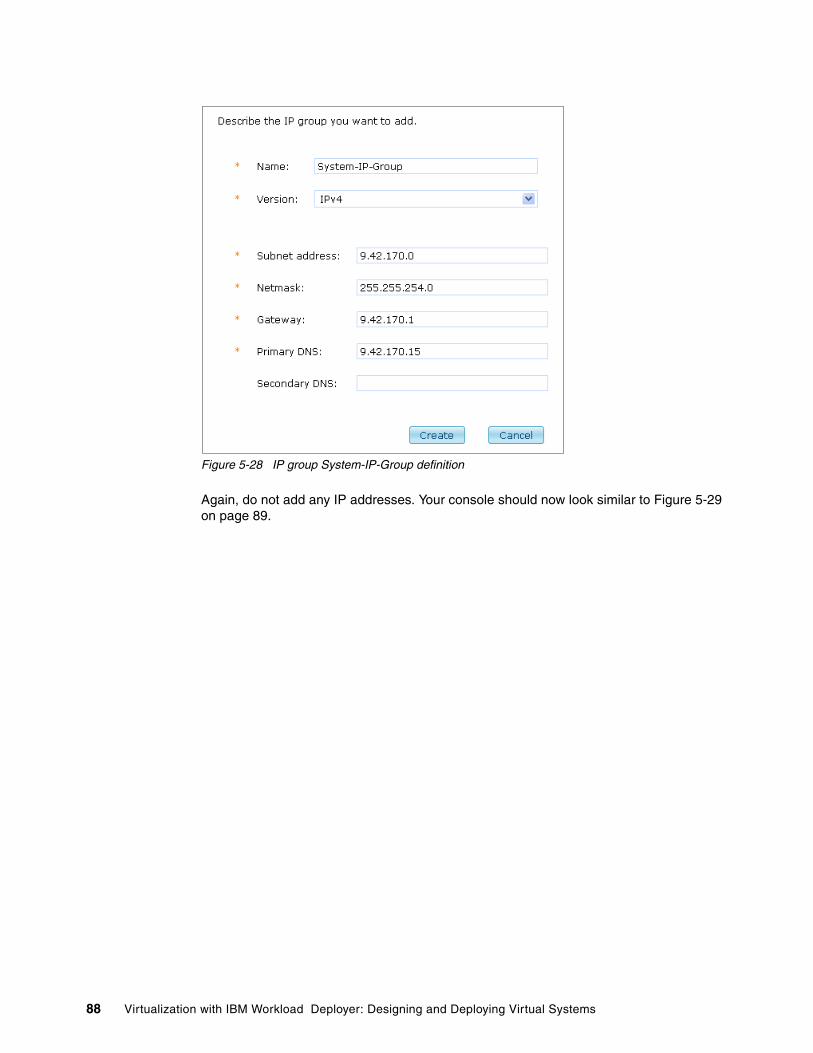
Figure 5-28 IP group System-IP-Group definition
Again, do not add any IP addresses. Your console should now look similar to Figure 5-29 on page 89.
88 Virtualization with IBM Workload Deployer: Designing and Deploying Virtual Systems

Figure 5-29 System-IP-Group definition
6. Repeat steps 3 and 4 to add a third group called Default-IP-Group.
Chapter 5. Configuring the IBM Workload Deployer 89

Figure 5-30 Default-IP-Group definition
7. This group will be used in the clone to extend functions for virtual images and for testing new virtual images, so we will assign a few IP address to this group. You can add IP addresses in one of two ways:
– Enter the IP address in the “start” field and click Add.– Enter the host names in the host names field, separated by a space, and click Add
Host Names.
We will enter the IP addresses in this example, as shown in Figure 5-31 on page 91.
Tip: When you add an IP address or host name, the IBM Workload Deployer attempts to look it up in the domain name server. If there are problems with this lookup, check your appliance settings to ensure that the Ethernet Interfaces are defined correctly, including the mask and that the domain name server is defined.
90 Virtualization with IBM Workload Deployer: Designing and Deploying Virtual Systems
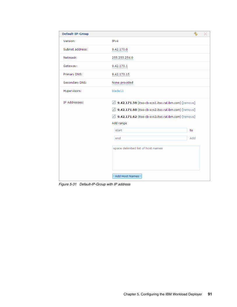
Figure 5-31 Default-IP-Group with IP address
Chapter 5. Configuring the IBM Workload Deployer 91

5.3.2 Adding the hypervisors
We now must add the resources where our virtual systems will run. Thus, we must provide hypervisors to IBM Workload Deployer to manage. To add hypervisors:
1. Navigate to Cloud Hypervisors, as shown in Figure 5-32.
Figure 5-32 Cloud menu for Hypervisors
2. Add a new hypervisor by clicking New ( ), as shown in Figure 5-33.
Figure 5-33 Add a new hypervisor
92 Virtualization with IBM Workload Deployer: Designing and Deploying Virtual Systems

3. Insert all of the information required in the pop-up window, and click OK. In Figure 5-34, we add blade9, one of our blades.
Figure 5-34 Adding blade9
4. After a few seconds, another window is displayed. This window contains the hypervisor’s certificate. Click Accept. You must accept the certificate to have IBM Workload Deployer able to deploy on it.
Figure 5-35 Accepting the hypervisor’s certificate
Now that the license is accepted, you should see the blade in maintenance mode, as shown in Figure 5-36.
Chapter 5. Configuring the IBM Workload Deployer 93

Figure 5-36 The blade is in maintenance mode
The blade is in maintenance mode because you have not completed the necessary configuration for it, including selecting the network, adding an IP Group, and selecting the data storage to use. We will do that later.
5. The first blade was successfully added to IBM Workload Deployer. We now must repeat steps 2 to 4 for all of the other blades that we want to add to the cloud. We do this for blade11, blade38, blade36, blade40, and blade45 in the hypervisor list, as shown in Figure 5-37.
Figure 5-37 Hypervisors’ list
5.3.3 Creating the cloud groups
Now that you defined the hypervisors, you must pool them in cloud groups. We created two separate cloud groups for our hypervisors: DMZ-Cloud-Group with Blade36 and System-Cloud-Group with the remaining Blades.
The first cloud group simulates our DMZ. To create the DMZ-Cloud-Group:
1. Select Cloud Cloud Groups, as shown in Figure 5-38.
Cloud groups: Cloud groups are a collection of hypervisors. When determining how to define the groups, keep the following rules in mind:
� A cloud group can contain only one type (ESX, PowerVM, or z/VM) of hypervisor� One hypervisor can belong to only one cloud group� A cloud group can contain one or more hypervisors
More information can be found in the IBM Workload Deployer Information Center in the topic About cloud groups at:
http://publib.boulder.ibm.com/infocenter/worlodep/v3r0m0/index.jsp?topic=/com.ibm.worlodep.doc/sr/cg/cgr_cloudgro.html
94 Virtualization with IBM Workload Deployer: Designing and Deploying Virtual Systems

Figure 5-38 Cloud menu
If you have not defined any cloud groups, you will only see the Default ESX Group in the cloud groups list, as shown in Figure 5-39. Notice the warning icon ( ) to the right of the cloud group. The reason for this warning is that at the moment, the cloud groups contain no hypervisors.
Figure 5-39 Cloud group list
2. We will use Default ESX Group for our clone and extend operations, so we need to add a hypervisor. Click Default ESX Group to open the configuration page.
3. To add a hypervisor to the DMZ-Cloud-Group, click in the Hypervisors input field, as shown in Figure 5-40. This brings up a list of the hypervisors. Select Blade11 to add it to the cloud group.
Chapter 5. Configuring the IBM Workload Deployer 95

Figure 5-40 Add a hypervisor
Adding a hypervisor does not eliminate the warnings. Because we have not started the hypervisor, there will be a new warning indicating that the hypervisor has not started (see Figure 5-41). Our hypervisors are still in maintenance mode. We will take care of starting the hypervisors after we create all the cloud groups.
Figure 5-41 Warning message
4. Now, we must add two more cloud groups. Click New ( ) to create a new cloud group.
Figure 5-42 Cloud group list
96 Virtualization with IBM Workload Deployer: Designing and Deploying Virtual Systems

5. Enter the name for the new cloud group, DMZ-Cloud-Group, enter a description, and select ESX as the hypervisor type, as shown in Figure 5-43, and click Create.
Figure 5-43 Cloud Group definition
6. You should now have two entries in the cloud group list, Default ESX group and DMZ-Cloud-Group, as shown in Figure 5-44.
Figure 5-44 Cloud group list with DMZ-Cloud-Group
Click the DMZ-Cloud-Group in the cloud groups list to open the configuration page.
7. Click in the Hypervisors input field, and select blade36 to add it to the cloud group. The resulting panel should be similar to Figure 5-45.
Figure 5-45 Blade36 added to the cloud group
8. Click in the Access granted to input field, and add ITSOopts. Click again in the field, and add ITSOdeps.
Figure 5-46 Grant access to the cloud group
Chapter 5. Configuring the IBM Workload Deployer 97
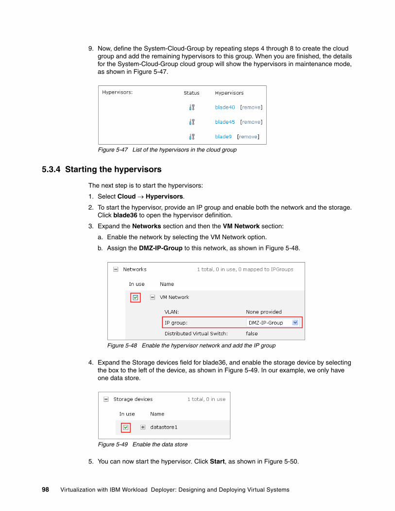
9. Now, define the System-Cloud-Group by repeating steps 4 through 8 to create the cloud group and add the remaining hypervisors to this group. When you are finished, the details for the System-Cloud-Group cloud group will show the hypervisors in maintenance mode, as shown in Figure 5-47.
Figure 5-47 List of the hypervisors in the cloud group
5.3.4 Starting the hypervisors
The next step is to start the hypervisors:
1. Select Cloud Hypervisors.
2. To start the hypervisor, provide an IP group and enable both the network and the storage. Click blade36 to open the hypervisor definition.
3. Expand the Networks section and then the VM Network section:
a. Enable the network by selecting the VM Network option.
b. Assign the DMZ-IP-Group to this network, as shown in Figure 5-48.
Figure 5-48 Enable the hypervisor network and add the IP group
4. Expand the Storage devices field for blade36, and enable the storage device by selecting the box to the left of the device, as shown in Figure 5-49. In our example, we only have one data store.
Figure 5-49 Enable the data store
5. You can now start the hypervisor. Click Start, as shown in Figure 5-50.
98 Virtualization with IBM Workload Deployer: Designing and Deploying Virtual Systems

Figure 5-50 Start the hypervisor
6. In the hypervisor list you should now see the hypervisor started, as in Figure 5-51.
Figure 5-51 Hypervisor list with blade36 started
7. Now, we must start the rest of the hypervisors. Repeat steps 2 through 6 to activate the network, activate the data store, and assign IP groups to each hypervisor as follows:
– blade40, blade45, and blade9: System-IP-Group– blade11: Default-IP-Group
8. When you are finished, the hypervisor list will look similar to Figure 5-52 on page 99.
Figure 5-52 Hypervisor list
9. Select Cloud Cloud Groups. Now that the hypervisors are started, the cloud groups must also be in a started state, as shown in Figure 5-53.
Tip: Blade36 was defined as a hypervisor in the DMZ-Cloud-Group. If you navigate back to the cloud group page, you can see that the DMZ-Cloud-Group is now active.
Chapter 5. Configuring the IBM Workload Deployer 99

Figure 5-53 Cloud groups in started state
5.4 Adding a new virtual image
IBM Workload Deployer comes with preinstalled images. You can use these images, or you can import the latest Hypervisor Edition images to the appliance.
In our sample, we used IBM WebSphere Application Server Hypervisor Edition V7.0.0.15 for Red Hat Linux Enterprise Server. There are three versions of this image: OVA, OVF, and ESX. We downloaded the OVA image since this is the version used by IBM Workload Deployer.
After you download the image, import the OVA file into the appliance. You can use both the GUI or the CLI to import the OVA file. To use the GUI, follow these steps:
1. Select Catalog Virtual Images, as shown in Figure 5-54 on page 100.
Figure 5-54 Catalog menu for virtual images
2. Click New ( ) to add a new image, as shown in Figure 5-55.
Getting the latest images: You can get the hypervisor images from the following IBM web site:
http://www-01.ibm.com/software/howtobuy/passportadvantage/pao_customers.htm
You must have an IBM Password Advantage account.
100 Virtualization with IBM Workload Deployer: Designing and Deploying Virtual Systems

Figure 5-55 List of images empty
3. To import the OVA file using the GUI, the OVA file must be accessible through an HTTP server. Provide the path to the OVA file, as shown in Figure 5-56. You must also provide the credentials required to log in to the HTTP server if needed. In our scenario, we do not need any credentials to access the file. After you provide all of the information needed, click OK.
Figure 5-56 Import OVA file
A new image now displays in the list of the virtual images that are available, as shown in Figure 5-57 on page 101.
Figure 5-57 OVA file during import
4. If you click the new virtual image link, the details about the image are imported. In Figure 5-58, the image is in a downloading state. Click Refresh periodically to see the current status.
Chapter 5. Configuring the IBM Workload Deployer 101

Figure 5-58 Current status of the import
5. When the import finishes, the name of the image changes to the one describing the content of the image, as shown in Figure 5-59.
Figure 5-59 Virtual image imported, but not ready for the usage
6. The next step is to accept the licenses. Click in the License agreement field, as shown in Figure 5-60.
Figure 5-60 License acceptance
7. A new window opens with a list of the licenses that are required for the image. Accept each license by clicking each link shown in Figure 5-61. A new window opens for each license that you click. Click Accept in the window, and continue to the next license.
102 Virtualization with IBM Workload Deployer: Designing and Deploying Virtual Systems

Figure 5-61 LIcenses to be accepted
8. When completed, all of the licenses that are listed have a green check mark to the left of the name, as shown in Figure 5-62. Click OK.
Figure 5-62 Licenses accepted
9. The image is now ready to be used, as indicated by the green check mark next to the license agreement and the green check mark next to the image, as shown in Figure 5-63. The Intelligent Management Pack feature is currently disabled.
Figure 5-63 Virtual image is active
10.To build our private cloud, we need both an image with the Intelligent Management Pack enabled and an image with the Intelligent Management Pack disabled. When imported, the image has this feature disabled, as shown in Figure 5-63 on page 103.
Chapter 5. Configuring the IBM Workload Deployer 103

Now we must clone this image to have a copy of the WebSphere Application Server Hypervisor Edition 7.0.0.15 where we can enable the Intelligent Management Pack. To clone the image, select the image that you want to clone from the image list on the GUI, and click Clone ( ).
11.The clone process requires that you provide information. In particular, you must provide the name of the cloned image and the version, as shown in Figure 5-64.
Click General Information to show the fields in Figure 5-64. Enter the following information:
– Name: WebSphere Application Server 7.0.0.15 with Intelligent Management Pack V61.1.3
– Description: WebSphere Application Server 7.0.0.15 with Intelligent Management Pack V61.1.3
– Version: 1.0
Click OK.
Figure 5-64 Cloned image details
12.This process takes some time to complete. While the cloning process take place, the new image displays in the virtual images list. If you click this image, you can see the details, as shown in Figure 5-65.
Figure 5-65 Cloning process
13.When the process completes, the new image is available. All of the licenses are accepted because you accepted the license in the original image. Now, you must enable the Intelligent Management Pack for this image. From the drop-down menu, select Enabled, as shown in Figure 5-66.
104 Virtualization with IBM Workload Deployer: Designing and Deploying Virtual Systems

Figure 5-66 Enable the Intelligent Management Pack
You now have all the basic components that are needed to set up the private cloud.
Chapter 5. Configuring the IBM Workload Deployer 105

106 Virtualization with IBM Workload Deployer: Designing and Deploying Virtual Systems

Chapter 6. Creating and customizing virtual images
In Chapter 5, “Configuring the IBM Workload Deployer” on page 71, we discussed the necessary preparations for our example environment. In this chapter, we continue with the customization of the environment by extending the images to suit our scenario.
This chapter includes the following topics:
� 6.1,“Uploading the script packages” on page 108� 6.2,“Extending the client image” on page 114� 6.3,“Extending the server image” on page 124� 6.4,“Confirming and locking the extended images” on page 127� 6.5,“Cloning the server image for the Deployment Manager” on page 136
To perform these actions, the IBM Workload Deployer user needs permission to create new catalog content and must be granted all access to the virtual image to be extended or must be assigned the Appliance administration role with full permission. The user, ITSOadm1, has the necessary rights.
6
© Copyright IBM Corp. 2011. All rights reserved. 107

6.1 Uploading the script packages
For our example, we need the following script packages:
� The first script package is for WebSphere eXtreme Scale client and server and consists of a ZIP archive named wxsAugment.zip.
� The second package is for IBM Tivoli Monitoring Agent and consists of a ZIP archive named imtagentconfig.zip.
The wxsAugment.zipThis script package augments the WebSphere Application Server profiles in the virtual machine with WebSphere eXtreme Scale to benefit from the eXtreme Scale functionality. The archive includes the cbscript.json and wxsAugment.sh files.
Example 6-1 contains the content of the cbscript.json configuration file. This file contains the script package definition and can also be used for defining variables. You will see an example of defining variables in a json script later in “The itmagentconfig.zip” on page 109. Variables, which are placed in the keys section of the json file, can be used to provide specific information to the processes executed by the script at deployment time.
Example 6-1 cbscript.json
{ "name": "WXS Augmentation", "version": "1.0.0", "description": "This script uses the WXS binaries to augment the existing WAS profile", "command": "/bin/sh /tmp/wxsAugment/wxsAugment.sh", "log": "/tmp/wxsAugment/wxsAugment.traceout", "location": "/tmp/wxsAugment", "timeout": "0", "commandargs": "", "keys": [ ]}
The wxsAugment.sh script, shown in Example 6-2, performs the profile augmentation. It stops the WebSphere Application Server processes, augments the profile, and then starts the processes again. The first line of the script gives the location of the virtualimage.properties file, which includes environment variables for the augmentation. The /etc/virtualimage.properties file comes by default in each of the Hypervisor Edition images. You will see an example of using this properties file later in “Creating a script package for future use” on page 167.
Example 6-2 wxsAugment.sh
source /etc/virtualimage.propertiescd /opt/IBM/WebSpherechown -R virtuser:users *if [ $PROFILE_TYPE == "custom" ] ; then su virtuser -c "$WAS_PROFILE_ROOT/bin/stopNode.sh" ls -l $WAS_PROFILE_ROOT/config/cells/CloudBurstCell_1/nodes/$NODE_NAME/servers su virtuser -c "$WAS_PROFILE_ROOT/bin/manageprofiles.sh -augment -profileName $PROFILE_NAME -profilePath $WAS_PROFILE_ROOT -templatePath $WAS_INSTALL_ROOT/profileTemplates/xs_augment/managed"
108 Virtualization with IBM Workload Deployer: Designing and Deploying Virtual Systems

ls -l $WAS_PROFILE_ROOT/config/cells/CloudBurstCell_1/nodes/$NODE_NAME/servers chown -R virtuser:users $WAS_INSTALL_ROOT/systemApps/isclite.ear ls -l $WAS_PROFILE_ROOT/config/cells/CloudBurstCell_1/nodes/$NODE_NAME/servers su virtuser -c "$WAS_PROFILE_ROOT/bin/startNode.sh"elif [ $PROFILE_TYPE == "default" ] ; then su virtuser -c "$WAS_PROFILE_ROOT/bin/stopServer.sh server1" ls -l $WAS_PROFILE_ROOT/config/cells/CloudBurstCell_1/nodes/$NODE_NAME/servers su virtuser -c "$WAS_PROFILE_ROOT/bin/manageprofiles.sh -augment -profileName $PROFILE_NAME -profilePath $WAS_PROFILE_ROOT -templatePath $WAS_INSTALL_ROOT/profileTemplates/xs_augment/default" ls -l $WAS_PROFILE_ROOT/config/cells/CloudBurstCell_1/nodes/$NODE_NAME/servers chown -R virtuser:users $WAS_INSTALL_ROOT/systemApps/isclite.ear ls -l $WAS_PROFILE_ROOT/config/cells/CloudBurstCell_1/nodes/$NODE_NAME/servers $WAS_PROFILE_ROOT/bin/iscdeploy.sh -restore su virtuser -c "$WAS_PROFILE_ROOT/bin/startServer.sh server1"else su virtuser -c "$WAS_PROFILE_ROOT/bin/stopManager.sh" ls -l $WAS_PROFILE_ROOT/config/cells/CloudBurstCell_1/nodes/$NODE_NAME/servers su virtuser -c "$WAS_PROFILE_ROOT/bin/manageprofiles.sh -augment -profileName $PROFILE_NAME -profilePath $WAS_PROFILE_ROOT -templatePath $WAS_INSTALL_ROOT/profileTemplates/xs_augment/dmgr" ls -l $WAS_PROFILE_ROOT/config/cells/CloudBurstCell_1/nodes/$NODE_NAME/servers chown -R virtuser:users $WAS_INSTALL_ROOT/systemApps/isclite.ear ls -l $WAS_PROFILE_ROOT/config/cells/CloudBurstCell_1/nodes/$NODE_NAME/servers $WAS_PROFILE_ROOT/bin/iscdeploy.sh -restore su virtuser -c "$WAS_PROFILE_ROOT/bin/startManager.sh"fi
The itmagentconfig.zipThe itmagentconfig.zip script package configures an IBM Tivoli Monitoring (ITM) agent installed in the virtual machine to report back to a Tivoli Enterprise Management Server instance.
The archive includes the following files:
� cbscript.json� configITMAgent.sh � readme.txt.
Example 6-3 shows the content of the cbscript.json configuration file. In the keys section, a variable called ITM_TEMS_HOSTNAME is defined. This variable is used to provide the host name value for a Tivoli Enterprise Management Server instance to the configITMAgent.sh script.
Example 6-3 cbscript.json for the itmagent
{ "name": "Configure ITM agent", "version": "1.0.0", "description": "This script configures an ITM agent installed in the virtual machine to report to a Tivoli Enterprise Management Server instance", "command": "/bin/sh /tmp/configITMAgent/configITMAgent.sh", "log": "", "location": "/tmp/configITMAgent", "timeout": "0", "commandargs": "", "keys": [
Chapter 6. Creating and customizing virtual images 109

{ "scriptkey": "ITM_TEMS_HOSTNAME", "scriptvalue": "", "scriptdefaultvalue": "" } ]}
The configITMagent.sh script configures the IBM Tivoli Monitoring agent with the host name of the IBM Tivoli Monitoring Server, as defined in the ITM_TEMS_HOSTNAME variable. Example 6-4 shows the content of this script.
Example 6-4 configITMagent.sh
#!/bin/sh## For IBM Workload Deployer# Script to change ITM agent config to point to correct ITM server#PROGNAME=`basename $0`BINDIR=`dirname "$0"`ITM_DIR=/opt/IBM/ITMITM_RSP=$BINDIR/configITMAgent.rspecho "----------------------------------------------"echo " Show environment variables"echo "----------------------------------------------"setecho "----------------------------------------------"echo " Stop ITM Agent"echo "----------------------------------------------"$ITM_DIR/bin/itmcmd agent stop lz echo "----------------------------------------------"echo " Build response file for config of ITM Agent "echo "----------------------------------------------"# Environment variable ITM_TEMS_HOSTNAME if [[ "$ITM_TEMS_HOSTNAME" = "" ]]; then echo "ITM TEMS hostname was not passed in! Default to localhost." ITM_TEMS_HOSTNAME=localhostfiecho "ITM TEMS Hostname is $ITM_TEMS_HOSTNAME"# remove old response file, if it existsrm -f $ITM_RSP# build new response fileecho "#ITM Response File" >$ITM_RSPecho "CMSCONNECT=YES" >>$ITM_RSPecho "HOSTNAME=$ITM_TEMS_HOSTNAME" >>$ITM_RSPecho "NETWORKPROTOCOL=ip.pipe" >>$ITM_RSPecho "----------------------------------------------"echo " Change config for ITM Agent "echo "----------------------------------------------"ITM_DIR/bin/itmcmd config -A -p $ITM_RSP lz #-----------------------------------------------------------------------------# remove response filerm -f $ITM_RSPecho "----------------------------------------------"echo " Start ITM Agent"
110 Virtualization with IBM Workload Deployer: Designing and Deploying Virtual Systems

echo "----------------------------------------------"$ITM_DIR/bin/itmcmd agent start lz echo ""echo "Done"
6.1.1 Uploading the WebSphere eXtreme Scale script package
To upload the WebSphere eXtreme Scale script package:
1. To complete the steps in this section, log into IBM Workload Deployer as ITSOadm1.
2. From the IBM Workload Deployer user interface, select Catalog Script Packages.
Figure 6-1 Choose “Script Packages” from the Catalog Menu
3. Click New, as shown in Figure 6-2.
Figure 6-2 Add a new script package
4. Provide a name for the script package, as shown in Figure 6-3. Click OK.
Figure 6-3 Name of the script package
An entry for the new script is displayed in the navigation column on the left, and a configuration page on the right opens.
5. Click Browse, and navigate to the wxsAugment.zip script package on your system, as shown in Figure 6-4 on page 112.
Chapter 6. Creating and customizing virtual images 111
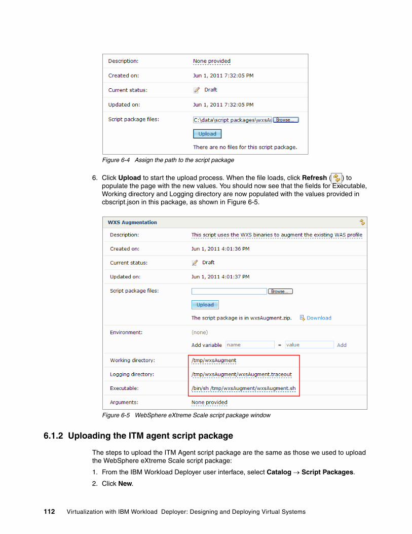
Figure 6-4 Assign the path to the script package
6. Click Upload to start the upload process. When the file loads, click Refresh ( ) to populate the page with the new values. You should now see that the fields for Executable, Working directory and Logging directory are now populated with the values provided in cbscript.json in this package, as shown in Figure 6-5.
Figure 6-5 WebSphere eXtreme Scale script package window
6.1.2 Uploading the ITM agent script package
The steps to upload the ITM Agent script package are the same as those we used to upload the WebSphere eXtreme Scale script package:
1. From the IBM Workload Deployer user interface, select Catalog Script Packages.
2. Click New.
112 Virtualization with IBM Workload Deployer: Designing and Deploying Virtual Systems
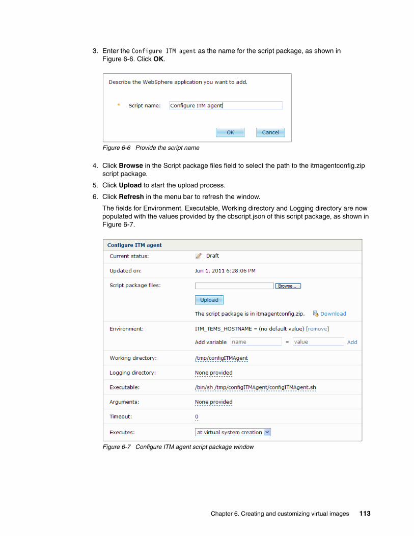
3. Enter the Configure ITM agent as the name for the script package, as shown in Figure 6-6. Click OK.
Figure 6-6 Provide the script name
4. Click Browse in the Script package files field to select the path to the itmagentconfig.zip script package.
5. Click Upload to start the upload process.
6. Click Refresh in the menu bar to refresh the window.
The fields for Environment, Executable, Working directory and Logging directory are now populated with the values provided by the cbscript.json of this script package, as shown in Figure 6-7.
Figure 6-7 Configure ITM agent script package window
Chapter 6. Creating and customizing virtual images 113

6.2 Extending the client image
In this step, we extend a base WebSphere Application Server virtual image and customize it by installing the WebSphere eXtreme Scale client and the IBM Tivoli Monitoring agent code. You create the client image by extending an existing image. We describe the following steps in this section:
� 6.2.1,“Cloning and deploying a virtual image” on page 114� 6.2.2,“Customizing the image” on page 117� 6.2.3,“Capturing the image” on page 124
6.2.1 Cloning and deploying a virtual image
The following steps describes the extension of our virtual image:
1. From the IBM Workload Deployer user interface, select Catalog Virtual Images, as shown in Figure 6-8.
Figure 6-8 Choose “Virtual Images” from the Catalog Menu
2. Click WebSphere Application Server 7.0.0.15 with Intelligent Management Pack 6.1.1.3, as shown in Figure 6-9. This is the image we want to extend.
Figure 6-9 Choose WebSphere Application Server 7.0.0.15
114 Virtualization with IBM Workload Deployer: Designing and Deploying Virtual Systems

3. Click Clone and extend in the menu bar to create a copy of the selected virtual image, as shown in Figure 6-10.
Figure 6-10 Choose the Clone and extent icon
In the dialog box that opens, shown in Figure 6-11, all three sections must be selected before you can go further. A section with no options selected means that information is missing from this category. After you select the link for the section and complete the information, the option is automatically selected.
Figure 6-11 Several types of information must be provided
4. Click General information to expand this section, as shown in Figure 6-12. The Name and Version fields are marked with a red star, which means that these fields are mandatory. The Description field is optional.
Enter the following values for the fields:
– Name: WAS7_WXS71Client_ITMagent– Description: WAS 7.0.0.15, WXS 7.1.0.0, ITM Base OS Agent– Version: 1.0.0
Figure 6-12 Enter Name and Version
5. Now, click Deployment configuration to expand this section, as shown in Figure 6-13 on page 116, and then:
– Choose Default ESX Group for the cloud group.
Chapter 6. Creating and customizing virtual images 115

– Enter a password for the default user virtuser on the virtual system, and then re-enter the password in the Verify password field. This is also the password for the root user.
Figure 6-13 Deployment configuration
6. Click Hardware configuration to expand this section, as shown in Figure 6-14. This section inherits the configuration information from the image that you just extended. In this case, no changes are needed.
Figure 6-14 Overview of the Hardware Configuration
7. Click OK. The image is deployed into the cloud. In the IBM Workload Deployer user interface, you can check the current status of the image creation process, as shown in Figure 6-15.
Figure 6-15 Status of the image creation process
116 Virtualization with IBM Workload Deployer: Designing and Deploying Virtual Systems

When the current status is The virtual system has been deployed and is ready to use, as shown in Figure 6-16, you can now customize the image, as explained in the next section.
Figure 6-16 The image creation process finished
6.2.2 Customizing the image
Now, you can customize the image. We install the WebSphere eXtreme Scale Client code and an IBM Tivoli Monitoring Agent on the deployed system. As a prerequisite, complete the following steps:
1. Obtain a copy of the software to install, and make it available to the virtual machine. In our case, we copy the software packages on the virtual machine. To store the files on the virtual machine, choose a temporary folder. After the installation of the software, you can delete the files.
2. Log on to the virtual machine.
8. After you are logged into the Virtual Machine, open a terminal. If you are not connected as root, enter su and the password that you assigned during the creation process of this image in step 5 on page 115 of Chapter 7.2.1. It is the same that the virtuser has.
Installing the WebSphere eXtreme Scale clientInstall the WebSphere eXtreme Scale client:
1. Change to the directory, where the install script resides.
2. Execute the install script.
Tip: When you perform the Clone and Extend for an image, a new pattern is created for the virtual system with the image. The pattern contains a stand alone server. If something goes wrong with the deploy of the image, for example, you do not have enough storage on the hypervisor or no IP addresses are available. Check the status fields for both the image and the pattern.
Logging into the virtual system:
You can use the IBM Workload Deployer user interface to connect to the virtual machine:
1. Click the Instances toggle button to expand a list of instance categories.
2. Click Virtual Systems.
3. Click WAS7_WXS71Client_ITMagent in the list of available instances on the left side of the user interface.
4. On the right side, click Virtual machines.
5. Click the virtual machine you want to connect to, which expands this section.
6. In the lower left corner of the expanded section, there is a link named VNC. Click this link to get a connection to your Virtual Machine.
7. Use the password that you assigned when creating the image in step 5 on page 115 of Chapter 7.2.1.
Chapter 6. Creating and customizing virtual images 117

3. In the IBM WebSphere eXtreme Scale 7.1.0.0 Installation Wizard Welcome window, click Next to continue. The License Agreement window opens.
4. Read and accept the agreement, and click Next.
5. Choose the installation location, as shown in Figure 6-17. Click Next.
Figure 6-17 Choose the installation directory
6. In the Confirmation window, choose the directory for the installation of the WebSphere eXtreme Scale client, and click Next.
118 Virtualization with IBM Workload Deployer: Designing and Deploying Virtual Systems

7. The Optional Features Installation window opens. For this image, you install only the WebSphere eXtreme Scale client, so select the Install the IBM WebSphere eXtreme Scale server option, as shown in Figure 6-18. Click Next.
Figure 6-18 Optional Feature Installation
8. In the Profile augmentation window, clear the DefaultAppSrv01 option, shown in Figure 6-19 on page 120, because we do not want to augment the profile at this point.
At the end of the customization process, you capture this image and all profiles are reset. The wxsAugment script package is executed at deploy time to augment the profile.
Click Next.
Chapter 6. Creating and customizing virtual images 119
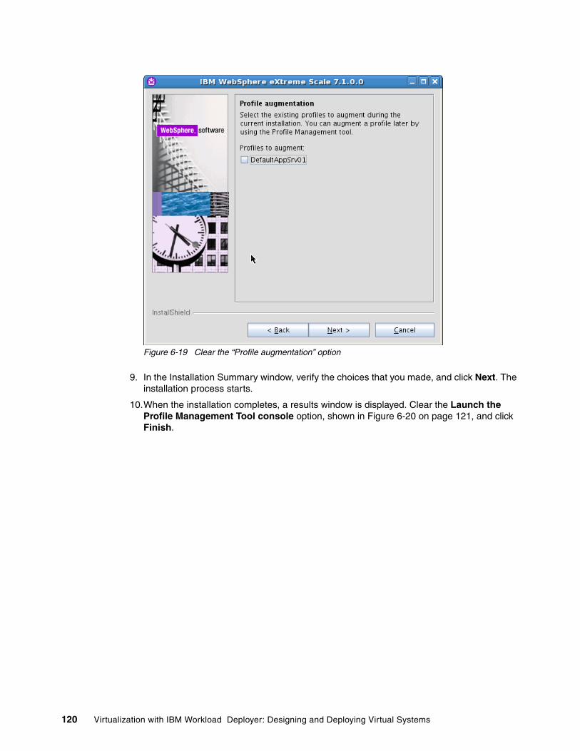
Figure 6-19 Clear the “Profile augmentation” option
9. In the Installation Summary window, verify the choices that you made, and click Next. The installation process starts.
10.When the installation completes, a results window is displayed. Clear the Launch the Profile Management Tool console option, shown in Figure 6-20 on page 121, and click Finish.
120 Virtualization with IBM Workload Deployer: Designing and Deploying Virtual Systems
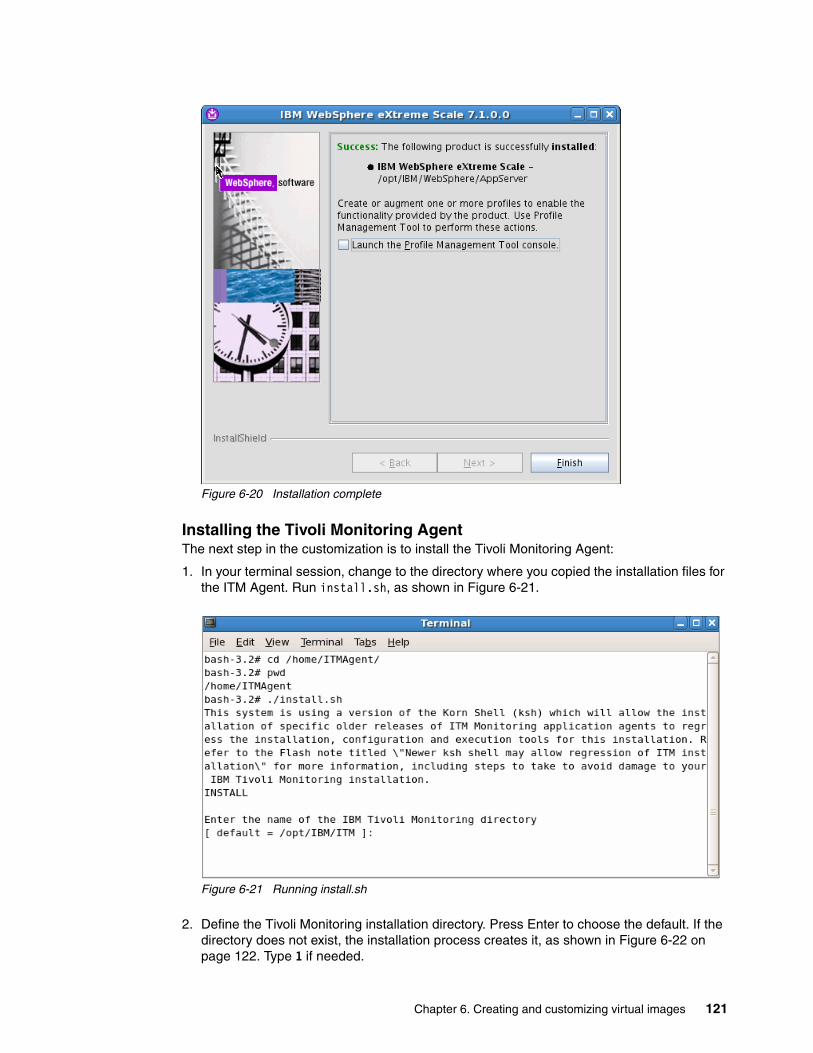
Figure 6-20 Installation complete
Installing the Tivoli Monitoring AgentThe next step in the customization is to install the Tivoli Monitoring Agent:
1. In your terminal session, change to the directory where you copied the installation files for the ITM Agent. Run install.sh, as shown in Figure 6-21.
Figure 6-21 Running install.sh
2. Define the Tivoli Monitoring installation directory. Press Enter to choose the default. If the directory does not exist, the installation process creates it, as shown in Figure 6-22 on page 122. Type 1 if needed.
Chapter 6. Creating and customizing virtual images 121
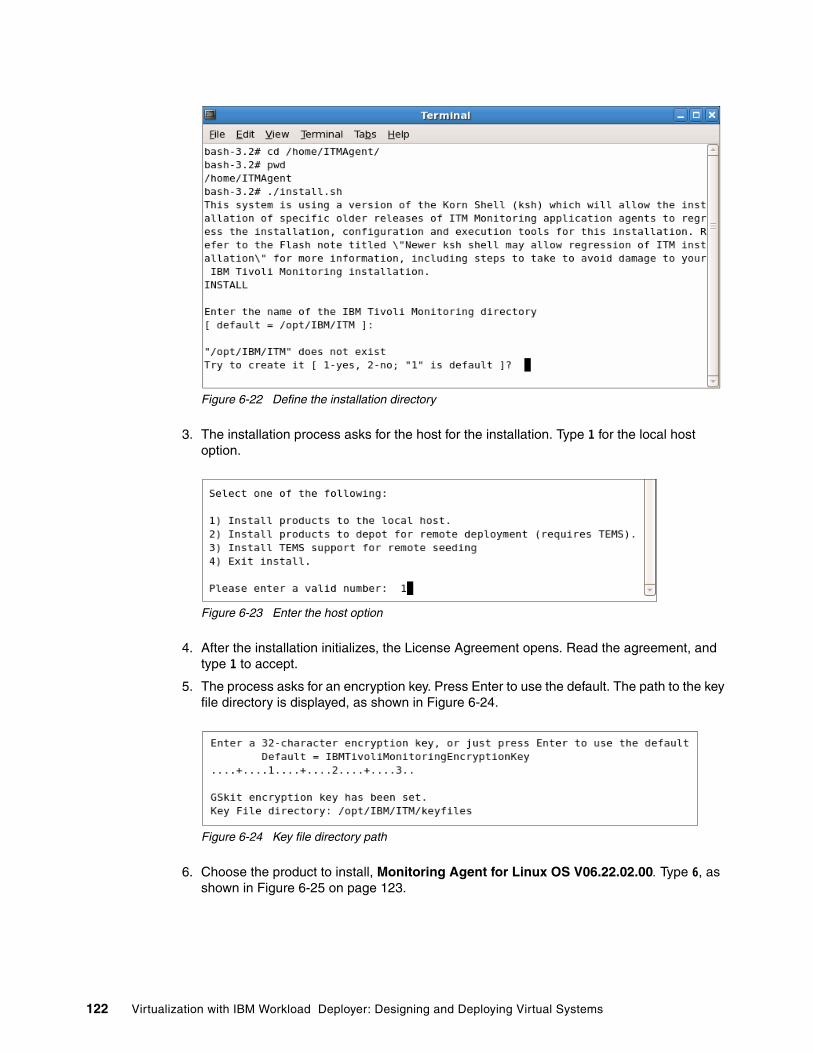
Figure 6-22 Define the installation directory
3. The installation process asks for the host for the installation. Type 1 for the local host option.
Figure 6-23 Enter the host option
4. After the installation initializes, the License Agreement opens. Read the agreement, and type 1 to accept.
5. The process asks for an encryption key. Press Enter to use the default. The path to the key file directory is displayed, as shown in Figure 6-24.
Figure 6-24 Key file directory path
6. Choose the product to install, Monitoring Agent for Linux OS V06.22.02.00. Type 6, as shown in Figure 6-25 on page 123.
122 Virtualization with IBM Workload Deployer: Designing and Deploying Virtual Systems

Figure 6-25 Choose the product to install
7. Type 1, and press Enter to confirm your selections. The installation begins. After the installation, you are prompted for additional product installations. Press Enter. You do not need to install any other products.
Figure 6-26 No additional product installations
Chapter 6. Creating and customizing virtual images 123

The ITM agent is installed. The agent still must be configured with the Tivoli Enterprise Server to which the agent provides the monitoring data. This configuration is done when we deploy the pattern with this image using the itmagentconfig script package.
6.2.3 Capturing the image
All the software is now installed on the client images, so now we can capture this image. By doing this, we store the customized image as an new image in the catalog:
1. In the IBM Workload Deployer user interface, select Catalog Virtual Images.
2. Click WAS7_WXS71Client_ITMagent. In the menu bar, click Capture, as shown in Figure 6-27.
Figure 6-27 Capture the image
3. Click OK to confirm the creation process. This process takes a while because a new virtual image is created based on the original virtual system that we customized. In the IBM Workload Deployer user interface, you can follow the status of the creation process, as shown in Figure 6-28.
Figure 6-28 Current status of the capturing process
6.3 Extending the server image
We extend the same base image that we used for the client, but this time we install the software that will run on the WebSphere eXtreme Scale server systems.
The next step is to customize and capture our server image. Again, we first create a new image:
1. From the IBM Workload Deployer user interface, select Catalog Virtual Images.
2. Click WebSphere Application Server 7.0.0.15 with Intelligent Management Pack 6.1.1.3.
3. Click Clone and extend in menu bar to create an extension of the selected virtual image.
4. Click General information to expand this section, as shown in Figure 6-29 on page 125. Use the following values for the Name, Description and Version field:
– Name: WAS7_WXS71Server_ITMagent– Description: WAS 7.0.0.15, WXS 7.1.0.0, ITM Base OS Agent – Version: 1.1.0
124 Virtualization with IBM Workload Deployer: Designing and Deploying Virtual Systems

Figure 6-29 Enter General information
5. In the Deployment Configuration section, choose the Cloud Group Default ESX Group, and provide a password, as shown in Figure 6-30.
Figure 6-30 Choose cloud group and provide password
6. In the Hardware Configuration, section no changes are needed. Click OK to deploy the image into the cloud.
6.3.1 Customizing the image
In this step, we install the WebSphere eXtreme Scale client and server code and the IBM Tivoli Monitoring agent. As a prerequisite, copy the product installation binaries to the virtual machine.
Installing the WebSphere eXtreme Scale server and clientTo install the WebSphere eXtreme Scale server and client:
1. Install the WebSphere eXtreme Scale server and client. Log into the virtual system, and change to the directory where the install script resides.
2. Execute the install script.
3. In the IBM WebSphere eXtreme Scale 7.1.0.0 Installation Wizard Welcome window, click Next to continue.
Chapter 6. Creating and customizing virtual images 125
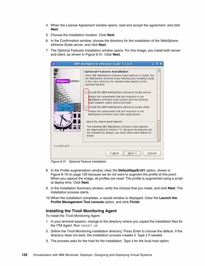
4. When the License Agreement window opens, read and accept the agreement, and click Next.
5. Choose the installation location. Click Next.
6. In the Confirmation window, choose the directory for the installation of the WebSphere eXtreme Scale server, and click Next.
7. The Optional Features Installation window opens. For this image, you install both server and client, as shown in Figure 6-31. Click Next.
Figure 6-31 Optional Feature Installation
8. In the Profile augmentation window, clear the DefaultAppSrv01 option, shown in Figure 6-19 on page 120 because we do not want to augment the profile at this point. When you capture the image, all profiles are reset. The profile is augmented using a script at deploy time. Click Next.
9. In the Installation Summary window, verify the choices that you made, and click Next. The installation process starts.
10.When the installation completes, a results window is displayed. Clear the Launch the Profile Management Tool console option, and click Finish.
Installing the Tivoli Monitoring AgentTo install the Tivoli Monitoring Agent:
1. In your terminal session, change to the directory where you copied the installation files for the ITM Agent. Run install.sh.
2. Define the Tivoli Monitoring installation directory. Press Enter to choose the default. If the directory does not exist, the installation process creates it. Type 1 if needed.
3. The process asks for the host for the installation. Type 1 for the local host option.
126 Virtualization with IBM Workload Deployer: Designing and Deploying Virtual Systems

4. After the installation initializes, the License Agreement opens. Read the agreement and type 1 to accept.
5. You are asked for an encryption key. Press Enter to use the default. The path to the key file directory displays.
6. Choose the product to install, which is Monitoring Agent for Linux OS V06.22.02.00. Type 6.
7. Type 1, and press Enter to confirm your selections. The installation begins. After the installation, you are prompted for additional product installations. Press Enter. You do not need to install any other products.
6.3.2 Capturing the image
To capture this new image, as described in Chapter 6.2.3,“Capturing the image” on page 124:
1. In the IBM Workload Deployer user interface, select Catalog Virtual Images. 2. Click WAS7_WXS71Server_ITMagent. In the menu bar, click Capture.3. Click OK to confirm the creation process.
6.4 Confirming and locking the extended images
The next step in the customization process is to check our new images. This step is recommended because after locking an image you cannot change it:
The check consists of three steps:
1. Create a test pattern with the extended images.2. Deploy this pattern.3. Confirm the pattern.
After a successful check, we will lock the extended images.
Creating a test patternIn this step we build test patterns with the new extended images. First, we build a test pattern for the WebSphere eXtreme Scale server image:
1. Select Patterns Virtual Systems, as shown in Figure 6-32.
Figure 6-32 Choose Virtual Systems
2. Click New.
3. Provide a name and description for the pattern, as shown in Figure 6-33 on page 128, and click OK:
– Name: TestServerPattern– Description: Test WXS Server and ITM client
Chapter 6. Creating and customizing virtual images 127

Figure 6-33 Describe the pattern
4. The properties page of your test pattern opens. In the menu bar, click Edit, shown in Figure 6-34, to edit your new pattern.
Figure 6-34 Click Edit
5. In the Pattern Editor, on the left side of the IBM Workload Deployer user interface, there is a list of several images, including your custom images. Click the image Standalone server WAS7_WXS71Server_ITMagent 1.1.0. Drag-and-drop this entry to the right side of the IBM Workload Deployer user interface. Figure 6-35 shows the result of this action.
Figure 6-35 Editing the test pattern
6. In the lower left corner of the IBM Workload Deployer console, click Scripts to open the script package section, as shown in Figure 6-36 on page 129. Scroll to the bottom of the list to find the WXS Augmentation script.
128 Virtualization with IBM Workload Deployer: Designing and Deploying Virtual Systems

Figure 6-36 Choose the script package
7. Drag-and-drop the WebSphere eXtreme Scale Augmentation script onto the Standalone server part in the canvas, as shown in Figure 6-37.
Figure 6-37 Add the WXS Augmentation script package to the Deployment Manager image
8. Now, drag-and-drop the Configure ITM agent script to the standalone server part. Figure 6-38 shows the results of this action.
Figure 6-38 Test pattern with two script packages
9. In the menu bar, click Done editing, as shown in Figure 6-39 on page 130.
Chapter 6. Creating and customizing virtual images 129

Figure 6-39 Finish editing
Your test pattern now looks like Figure 6-40.
Figure 6-40 Custom test pattern
Deploying the test patternThe next step is to deploy this new pattern:
1. In the menu bar, click Deploy in the cloud, as shown in Figure 6-41.
Figure 6-41 Deploy in the cloud
2. Type WXS Server Test as the name of the virtual system, as shown in Figure 6-42 on page 131.
130 Virtualization with IBM Workload Deployer: Designing and Deploying Virtual Systems

Figure 6-42 Describe the virtual system
3. Click Choose Environment, and ensure that the Default ESX group is selected.
Figure 6-43 Select the cloud group
4. Click Configure virtual parts to expand that option, and click Standalone server. A window opens with values for the stand alone server, as shown in Figure 6-44 on page 132. In the first part of this window, no changes are needed.
Chapter 6. Creating and customizing virtual images 131

Figure 6-44 Upper part of the additional information panel
5. Scroll to the end of that window, as shown in Figure 6-45, and perform these tasks:
a. Provide passwords for the root and the WebSphere administrative user.
b. Enter the host name of your ITM Server. This is where the ITM_TEMS_HOSTNAME variable defined in our cbscript.json for the itmagent script package is now used (See “The itmagentconfig.zip” on page 109).
Figure 6-45 Provide passwords and the hostname of your IBM Tivoli Monitoring Server
132 Virtualization with IBM Workload Deployer: Designing and Deploying Virtual Systems

c. Click OK to close the configuration for the virtual parts.
6. Click OK again to deploy the pattern.
The view automatically switches to the Instances Virtual Systems view. Deploying the new WXS Server Test virtual system can take some time. Click Refresh ( ) to see the current status. When the deploy is complete, a message is displayed that indicates the virtual system is ready to use, as shown in Figure 6-46.
Figure 6-46 Deploy is complete
Confirming the patternNow we are ready to check our customized image:
1. In the Instances Virtual Systems view, click the WXS Server Test virtual system in the navigator column, and then click Virtual machines in the details page. Select the name of your virtual machine to expand the configuration overview of this virtual machine, as shown in Figure 6-47 on page 134.
Chapter 6. Creating and customizing virtual images 133

Figure 6-47 Virtual machine information for the virtual system
2. Scroll to the end of this section to see information about the script packages used in the pattern, as shown in Figure 6-48.
Figure 6-48 Script packages of the test pattern
Click the link for the remote_std_out.log file for the WXS Augmentation script package.
3. Look for a message that contains the text Instconfsuccess: Profile augmentation succeeded. In addition, look for messages that indicate that the instance successfully restarted.
4. Log into the virtual system, and browse the augmentation log. In our example, it is the /opt/IBM/WebSphere/Profiles/logs/manageprofiles/DefaultAppSrv01_augment.log. Look
134 Virtualization with IBM Workload Deployer: Designing and Deploying Virtual Systems

for any errors. At the end of this file, the success message in Figure 6-49 on page 135 is displayed.
Figure 6-49 The DefaultAppSrv01_augment Log with an INSTCONFSUCCESS message
5. Click the WebSphere link, as shown in Figure 6-48 on page 134, to connect to the Deployment Manager.
Clicking this link opens a new web browser with the WebSphere Application Server console.You are now going to check if the profile augmentation is also visible in the WebSphere Application Server administrative console.
6. On the left side of the administrative console, click Servers Server Types WebSphere application servers. On the right side, there are two entries in the version column, as shown in Figure 6-50. The WXS 7.1.0.0 entry indicates the profile is augmented for WebSphere eXtreme Scale.
Figure 6-50 Check the version info
7. Close the administrative console.
8. In the IBM Workload Deployer interface, check the log files for the Configure ITM agent script. Click the link for the remote_std_out.log file of the script package. Look for messages indicating that the configuration of the ITM agent started and then completed and that the agent was restarted.
9. Log into the virtual system, and check the /opt/IBM/ITM/logs/itm_install.trc file for errors. The file should contain messages that look like those in Figure 6-51 on page 136.
Chapter 6. Creating and customizing virtual images 135

Figure 6-51 itm_install.trc file without errors
10.Log onto your IBM Tivoli Enterprise Portal server to verify that there is an entry for the system in the Navigator Physical view. You might need to refresh the view to see the entry.
11.After you verify that the image and pattern are working, you can delete the test pattern and virtual system to free up resources.
Locking the imagesAfter locking the image, it is no longer possible to change it. To lock the image:
1. In the user interface, select Catalog Virtual images.
2. In the list of images, click WAS7_WXS71Server_ITMagent.
3. In the menu bar, click Make read-only, as shown in Figure 6-52.
Figure 6-52 Lock the image
4. Click OK to confirm the lock.
Testing and locking the client imageCreate, deploy, and test a pattern using the client image WAS7_WXS71Client_ITMagent 1.0.0.The steps to do this are the same as used for the server image. When you confirm that the image and scripts are working correctly, delete the test pattern and virtual system, and then lock this image too.
6.5 Cloning the server image for the Deployment Manager
The last step of the customization of our environment is to create an image for the Deployment Manager for the WebSphere Application Server cell. To create this image, we clone the WebSphere eXtreme Scale Server image and enable the Intelligent Management Pack for that clone:
1. From the IBM Workload Deployer user interface, select Catalog Virtual Images.
2. Select WAS7_WXS71Server_ITMagent.
3. Click Clone in the menu bar to create an extension of the selected virtual image, as shown in Figure 6-53.
Figure 6-53 Choose the Clone icon to create a clone of the selected image
136 Virtualization with IBM Workload Deployer: Designing and Deploying Virtual Systems

4. Insert the following values in the dialog box that appears:
– Name: WAS7_WXS71Server_IMP_ITMagent– Description:WAS7_WXS71Server_ITMagent with IMP enabled– Version: 1.1.1
Figure 6-54 Insert the Name, Description and Version of the cloned image
5. Because you are only creating a clone, the Deployment and Hardware configuration cannot be edited. Click OK.
6. In the properties page of this new clone image, choose Enabled from the drop-down list for the Intelligent Management Pack, as shown in Figure 6-55.
Figure 6-55 Property panel of the WAS7_WXS71_IMP_ITMagent image
The customization of our example environment is finished. The next step is to create a custom pattern and environment, which we describe next in Chapter 7, “Creating the pattern and environment profiles” on page 139.
Chapter 6. Creating and customizing virtual images 137

138 Virtualization with IBM Workload Deployer: Designing and Deploying Virtual Systems

Chapter 7. Creating the pattern and environment profiles
This chapter describes the creation of a pre-production pattern and a pre-production environment profile using the images and script packages that we built in Chapter 6, “Creating and customizing virtual images” on page 107.
Environment profiles can provide several benefits when deploying patterns. In this chapter, we use environment profiles to control the placement of virtual machines on separate cloud groups and the assignment of IP addresses to virtual machines.
This chapter includes the following topics:
� 7.1, “Creating a pattern” on page 140� 7.2, “Creating an environment profile” on page 149� 7.3, “Deploying the pattern using the environment profile” on page 152
7
© Copyright IBM Corp. 2011. All rights reserved. 139

7.1 Creating a pattern
In this section, a pattern is created from the virtual images. Because the images were built and the scripts were uploaded by the administrator, and our patterns are created by someone in the operations role, we start by editing the access permissions for the script packages uploaded in the last chapter.
For this task, make sure that you are logged into the IBM Workload Deployer user interface as a user of the ITSOadm group because the user ITSOadm1 is the owner of the script packages:
1. Select Catalog script packages. The script packages that are available are on the left side.
2. Click WXS Augmentation.
3. On the right side of the user interface, you see the properties of this script package. Double-click in the Add more box of the Access granted to area, as shown in Figure 7-1 on page 141.
140 Virtualization with IBM Workload Deployer: Designing and Deploying Virtual Systems

Figure 7-1 Click Add more to open the user and group list
4. When the box with the users and groups opens, shown in Figure 7-2, click ITSOopts.
Figure 7-2 Choose the ITSOopts group
Chapter 7. Creating the pattern and environment profiles 141

5. As shown in Figure 7-3, the ITSOopts group is added to the list of users and groups that have read access to the script package. The read link is a toggle switch that allows you to choose read, write, or all, as the permission setting. To add this script package to patterns, the ITSOopts group must read permissions so that we can leave the permission set to read.
Figure 7-3 Access granted to the ITSOopts user group
6. Repeat steps 2 through 5 for the Configure ITM agent script package.
7. Log out and then log in as ITSOopt1. This user is a member of the ITSOopts group and inherits the permissions from the group.
8. Create the pattern. Select Patterns Virtual Systems.
9. Click New to open the New pattern description dialog box.
10.Type the name of the pattern, ITSO pre-production, as shown in Figure 7-4. Add a description for that pattern. When you finish, click OK.
Figure 7-4 Enter Name and Description of your pattern
Figure 7-5 on page 143 shows the new pattern. The topology section is empty.
142 Virtualization with IBM Workload Deployer: Designing and Deploying Virtual Systems

Figure 7-5 The new ITSO pre-production pattern
11.To edit this pattern, click Edit ( ) in the menu bar.
12.On the left side of the panel, there is a list of virtual images that you can choose to create a pattern. Click the image Deployment manager WAS7_WXS71Server_IMP_ITMagent 1.1.1, as shown in Figure 7-6.
Drag-and-drop this image to the right side of your IBM Workload Deployer user interface.
Figure 7-6 Add a Deployment Manager image to the pattern
Tip: To filter the list of images, type characters to filter on in the box before the list, as we did in Figure 7-6 by typing “dep” to find the deployment manager parts. To get the full list back, simply clear the box.
Chapter 7. Creating the pattern and environment profiles 143
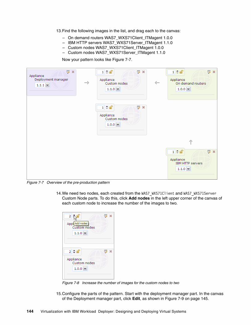
13.Find the following images in the list, and drag each to the canvas:
– On demand routers WAS7_WXS71Client_ITMagent 1.0.0– IBM HTTP servers WAS7_WXS71Server_ITMagent 1.1.0– Custom nodes WAS7_WXS71Client_ITMagent 1.0.0– Custom nodes WAS7_WXS71Server_ITMagent 1.1.0
Now your pattern looks like Figure 7-7.
Figure 7-7 Overview of the pre-production pattern
14.We need two nodes, each created from the WAS7_WXS71Client and WAS7_WXS71Server Custom Node parts. To do this, click Add nodes in the left upper corner of the canvas of each custom node to increase the number of the images to two.
Figure 7-8 Increase the number of images for the custom nodes to two
15.Configure the parts of the pattern. Start with the deployment manager part. In the canvas of the Deployment manager part, click Edit, as shown in Figure 7-9 on page 145.
144 Virtualization with IBM Workload Deployer: Designing and Deploying Virtual Systems

Figure 7-9 Click Edit to see the properties of the Deployment Manager part
16.A dialog box opens that shows the properties that you can edit and lock for that image. In our example, the deployer group deploys this pattern and must make a few changes to the pattern at deploy time. Lock everything except the cell and node name fields by clicking Lock for each remaining field, as shown in Figure 7-10. The cell and node name must be editable so that this information can be provided by the deployment group when the pattern is deployed.
Figure 7-10 Lock the properties by clicking the lock symbol
17.Scroll down to lock the Feature packs property, and lock the field, as shown in Figure 7-11.
Figure 7-11 Lock the Feature packs
Chapter 7. Creating the pattern and environment profiles 145

18.Scroll down to see the lower part of the dialog box. Enter the password for the root user and the WebSphere administrative user. Lock everything except the password for the virtuser, as shown in Figure 7-12. When finished, click OK.
Figure 7-12 Lower part of the property dialog box
19.Repeat steps 15 - 17 for the rest of the parts of this pattern to lock all the properties except the node name and the WebSphere administrative password.
20.Add the scripts to the parts:
a. In the navigation column, click Scripts.
b. Drag the WXS Augmentation script to the Deployment Manager and Custom node parts.
c. Drag the Configure ITM agent script to the Deployment Manager and Custom node parts.
The pattern now looks like Figure 7-13 on page 147.
146 Virtualization with IBM Workload Deployer: Designing and Deploying Virtual Systems
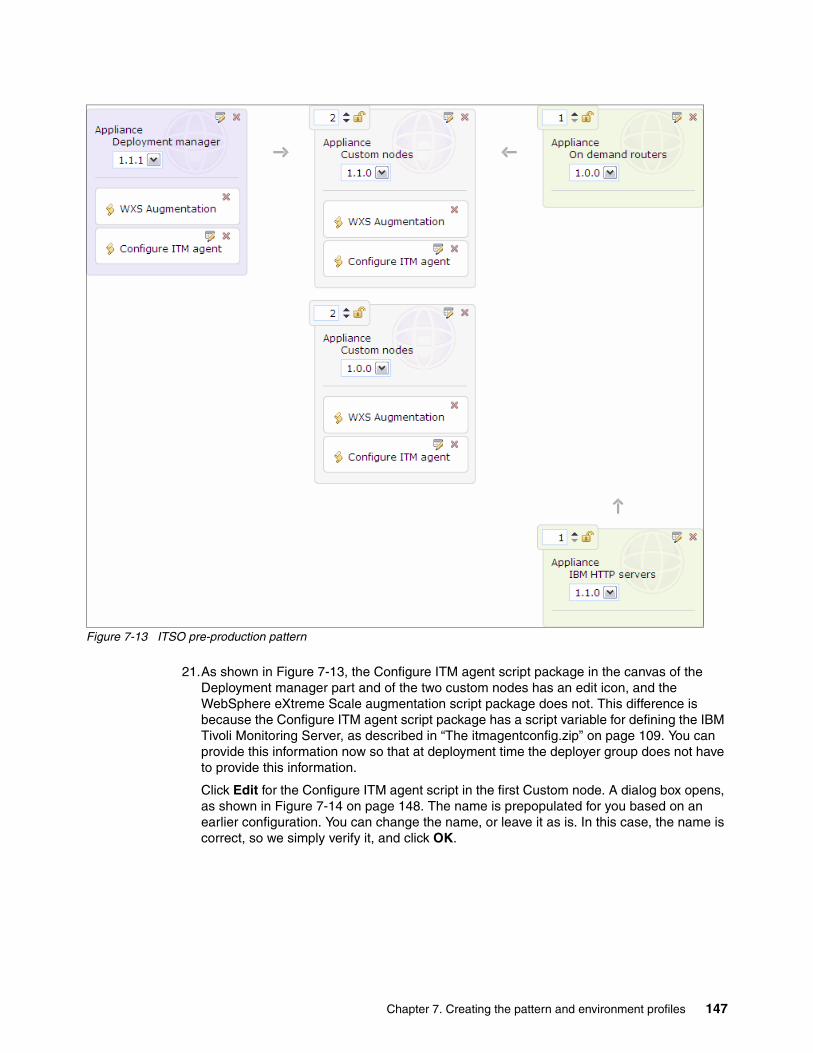
Figure 7-13 ITSO pre-production pattern
21.As shown in Figure 7-13, the Configure ITM agent script package in the canvas of the Deployment manager part and of the two custom nodes has an edit icon, and the WebSphere eXtreme Scale augmentation script package does not. This difference is because the Configure ITM agent script package has a script variable for defining the IBM Tivoli Monitoring Server, as described in “The itmagentconfig.zip” on page 109. You can provide this information now so that at deployment time the deployer group does not have to provide this information.
Click Edit for the Configure ITM agent script in the first Custom node. A dialog box opens, as shown in Figure 7-14 on page 148. The name is prepopulated for you based on an earlier configuration. You can change the name, or leave it as is. In this case, the name is correct, so we simply verify it, and click OK.
Chapter 7. Creating the pattern and environment profiles 147

Figure 7-14 Enter the host name of your IBM Monitoring Server
22.Edit the Configure ITM agent script for the second Custom node.
23.Edit the Configure ITM agent script for the Deployment Manager.
24.Click Done editing in the menu bar, as shown in Figure 7-15.
Figure 7-15 Click Done editing when finished
25.The deployer group needs permission to access this pattern. To provide this permission, double-click Add more in the list of Access granted to field, shown in Figure 7-16.
Figure 7-16 The deployer group needs Access permission to this pattern
Click ITSOdeps to give the deployment group the permission to read this pattern. See Figure 7-17 on page 149.
148 Virtualization with IBM Workload Deployer: Designing and Deploying Virtual Systems

Figure 7-17 The ITSOdeps group has now the necessary rights to deploy this pattern
Now, the preproduction pattern is ready to use.
7.2 Creating an environment profile
The goal of this section is to create an environment profile that enables you to choose several cloud groups for the ITSO preproduction pattern and to assign specific IP addresses to each virtual machine in this pattern at deployment time.
To create an environment profile:
1. Make sure that you are logged in as ITSOopt1.
2. Select Cloud Environment Profiles.
3. Click New.
4. In the environment profile description dialog box, enter the following values for the fields:
– Name: ITSO pre-prod profile– Description: ITSO pre-production profile– Hypervisor type: ESX
5. Open the pull-down menu for the Environment field, shown in Figure 7-18, to see a list of predefined entries. These entries can be used during deployment to narrow down the list of environment profiles to choose from. Choose Pre-Production, and click OK.
Figure 7-18 Enter the environment profile information
In Figure 7-19 on page 150, you see your new environment profile. The current status of the profile lets you know that more information is needed before you can use it.
Chapter 7. Creating the pattern and environment profiles 149

Figure 7-19 The new environment profile
6. Change the value for the field IP addresses provided by. Choose Pattern Deployer, as shown in Figure 7-20. Selecting this option allows you to define the IP addresses for each part of your pattern.
Figure 7-20 Choose the IP address provider
7. Define the cloud groups that will be available for selection when you deploy a pattern using this environment profile. Click in the Add more box of the cloud groups field, as shown in Figure 7-21.
Figure 7-21 Click in the Add more box add cloud groups to the environment profile
You get a drop-down list with the available cloud groups, as shown in Figure 7-22 on page 151. Choose DMZ-Cloud-Group first.
150 Virtualization with IBM Workload Deployer: Designing and Deploying Virtual Systems

Figure 7-22 The drop down list of available cloud groups
As shown in Figure 7-23, the Deploy to cloud groups field is extended by the DMZ-Cloud-Group.
Figure 7-23 Extended cloud group field
8. Click Add more again, and add the cloud group System-Cloud-Group. The result is shown in Figure 7-24.
Figure 7-24 Your example cloud groups has been added
9. Provide the IP groups for the cloud groups. To do that, first expand the DMZ-Cloud-Group, as shown in Figure 7-25.
Select the In use option of the DMZ-IP-Group, as shown in Figure 7-25.
Figure 7-25 Check the DMZ-IP-Group
Chapter 7. Creating the pattern and environment profiles 151
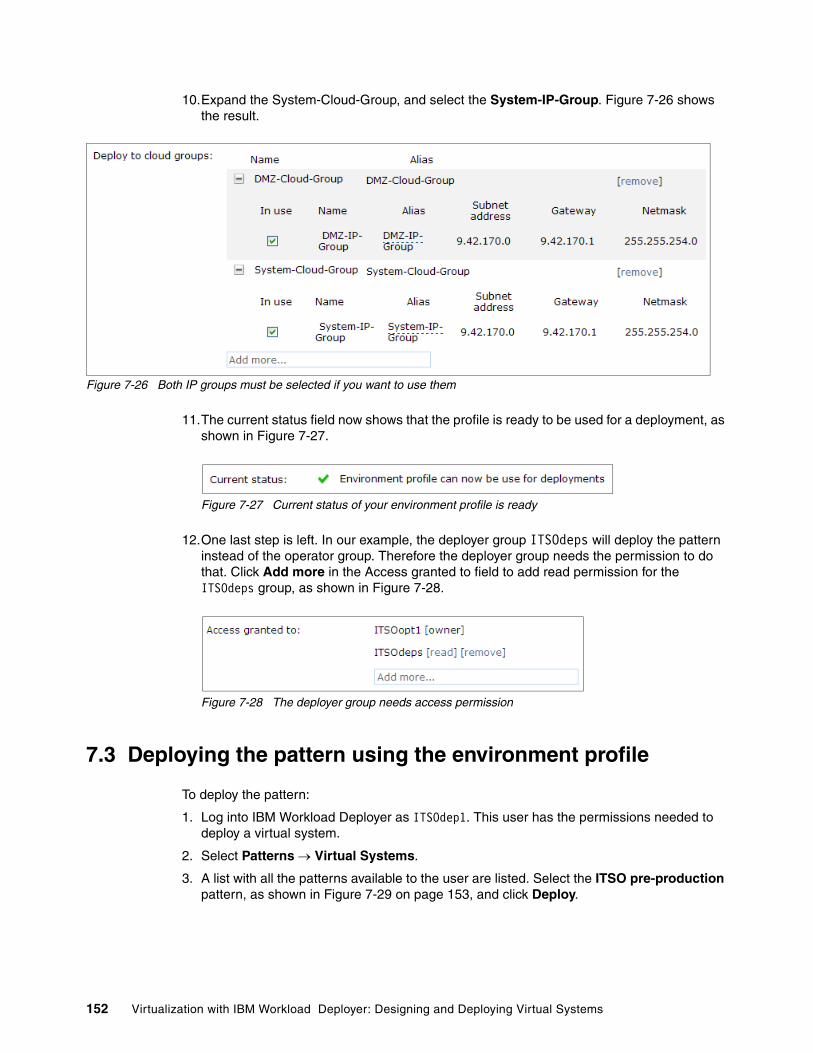
10.Expand the System-Cloud-Group, and select the System-IP-Group. Figure 7-26 shows the result.
Figure 7-26 Both IP groups must be selected if you want to use them
11.The current status field now shows that the profile is ready to be used for a deployment, as shown in Figure 7-27.
Figure 7-27 Current status of your environment profile is ready
12.One last step is left. In our example, the deployer group ITSOdeps will deploy the pattern instead of the operator group. Therefore the deployer group needs the permission to do that. Click Add more in the Access granted to field to add read permission for the ITSOdeps group, as shown in Figure 7-28.
Figure 7-28 The deployer group needs access permission
7.3 Deploying the pattern using the environment profile
To deploy the pattern:
1. Log into IBM Workload Deployer as ITSOdep1. This user has the permissions needed to deploy a virtual system.
2. Select Patterns Virtual Systems.
3. A list with all the patterns available to the user are listed. Select the ITSO pre-production pattern, as shown in Figure 7-29 on page 153, and click Deploy.
152 Virtualization with IBM Workload Deployer: Designing and Deploying Virtual Systems

Figure 7-29 Deploy the pattern
4. Provide all of the information requested in the dialog box shown in Figure 7-30:
a. Type the name of the virtual system, ITSO pre-production system.
Figure 7-30 Dialog window for virtual system deployment
b. For our deployment, we must change the environment default behavior. Select Choose Environment Choose profile Pre-production, as shown in Figure 7-31 on page 154.
Chapter 7. Creating the pattern and environment profiles 153

Figure 7-31 Choose environment profile
c. Review the Schedule deployment section. The default is to deploy the system immediately and for the system to run until you manually delete it. We do not want to schedule the deployment, so leave the default options, as shown in Figure 7-32.
Figure 7-32 Deployment schedule
d. To complete the deployment, provide the information required for each of the parts composing the pattern. Click Configure virtual parts, as shown in Figure 7-33 on page 155.
154 Virtualization with IBM Workload Deployer: Designing and Deploying Virtual Systems

Figure 7-33 Virtual part list
e. Click Deployment Manager and provide the required information, as shown in Figure 7-34:
• Cloud group: System-Cloud-Group• IP Group: System-IP-Group• IP address: 9.42.171.64
Figure 7-34 Deployment manager configuration
The options you see here will vary depending on how you created the pattern. Options in the pattern that are locked, for example, the root password, are not shown in the configuration.
As shown in Figure 7-34, in the lower part of this dialog box, the field for the host name of the IBM Tivoli Monitoring server is already populated. This is because you defined this value when you edited the Configure ITM agent script package in the ITSO Pre-production pattern. This value is editable because you did not lock this field.
Click OK after you complete the configuration.
f. Click each part in the pattern, and complete the fields. Every part, with the exception of the IBM HTTP servers part, will be in the System-Cloud-Group and will use the System-IP-Group.
The IBM HTTP servers part uses the DMZ-Cloud-Group and DMZ-IP-Group, as shown in Figure 7-35 on page 156.
Chapter 7. Creating the pattern and environment profiles 155

Figure 7-35 Choose the DMZ-IP-Group for the HTTP servers in this example
5. The dialog window now has all green check marks next to the entries, as shown in Figure 7-36.
Figure 7-36 The virtual system is ready to be deployed
6. Click OK to start the deployment. You are redirected to the virtual systems page, where you can follow the status of the deploy. Click Refresh occasionally to check the status.
156 Virtualization with IBM Workload Deployer: Designing and Deploying Virtual Systems

Figure 7-37 Processing request
After the deployment finishes, you can access your new system.
Chapter 7. Creating the pattern and environment profiles 157

158 Virtualization with IBM Workload Deployer: Designing and Deploying Virtual Systems
Chapter 8. Configuring the pre-production system
When an IT organization prepares for a new application, they typically configure one system manually and deploy their applications to it. This configuration must be repeated as the application moves from one stage to another. The best way to promote the configuration for deployment to subsequent stages is to automate this process, reducing the time needed to create the new system and limiting the possibility of introducing errors that often occur when multiple systems are manually configured.
In our scenario, the deployment of the pre-production virtual system using IBM Workload Deployer resulted in a cell with all the nodes federated and the On Demand Router (ODR) and the web server configured for the use. Additional manual configuration is now required before the application is deployed. Our application is really simple, so these steps are limited.
In this chapter, we perform the final configuration of the pre-production environment. The objective is to bring the system to the state that we want to repeat in the production deployment and to record the information required to automate the process in the future.
This chapter contains the following topics:
� 8.1, “Manual configuration steps for the pre-production environment” on page 160
� 8.2, “Installing the fix pack” on page 160
� 8.3, “Enabling the log command assistance functionality” on page 170
� 8.4, “WebSphere eXtreme Scale configuration” on page 172
� 8.5, “Creating and configuring the cluster for the grid containers” on page 178
� 8.6, “Deploying the business application and configuring the session persistence” on page 189
� 8.7, “Starting the dynamic cluster” on page 202
� 8.8, “Configuring the on demand router” on page 203
� 8.9, “Testing the configuration” on page 206
8
© Copyright IBM Corp. 2011. All rights reserved. 159

8.1 Manual configuration steps for the pre-production environment
In Chapter 7, “Creating the pattern and environment profiles” on page 139, we created the ITSO pre-production pattern and deployed it. The ITSO pre-production system is now running on our cloud, but it only has a basic configuration that includes:
� The IBM Tivoli Monitoring agent is configured to register itself to the IBM Tivoli Enterprise Monitoring Server
� The profiles are augmented with the WebSphere eXtreme Scale functionalities
We (in the role of the WebSphere system administrator) are now going to work on this system to create a working and stable configuration to run the application. Before starting the configuration, we install the latest fix pack for WebSphere eXtreme Scale (at the time of the creation of this book, the latest version available is 7.1.0.2).
Next, we create a simple script package to automate the installation of the fix pack onto other systems, for example the production system, so that no manual installation of the fix is needed in future deployments.
The configuration steps required are:
1. Install a fix pack.2. Create a WebSphere eXtreme Scale cluster to store the session data.3. Create a dynamic cluster to host our application.4. Configure the application to store session data on WebSphere eXtreme Scale.5. Configure the On Demand Router (ODR).
8.2 Installing the fix pack
Fix Pack 2 for WebSphere eXtreme Scale must be installed on five virtual machines:
� The deployment manager machine� The two custom nodes where the application will run� The two custom nodes where the grid will run
Before we begin, we must download the fix pack and copy it on the previously listed virtual images.
Creating the dynamic cluster: Using IBM Workload Deployer you can define a dynamic cluster by editing a pattern. We decided not to use this option, but defined the cluster by hand because by default IBM Workload Deployer tries to create a dynamic cluster on all of the available custom nodes. This means that the membership policy of the dynamic cluster includes both the custom node with the Intelligent Management Pack enabled and the custom node where it is not enabled.
You can choose to have IBM Workload Deployer to create the dynamic cluster for you. You only need to update the membership policy after the deployment.
160 Virtualization with IBM Workload Deployer: Designing and Deploying Virtual Systems

To install the fix pack, we followed the these steps:
1. Log in the WebSphere Application Server administrative console.
2. Stop the custom nodes:
a. Select System Administration Nodes.b. Check the box for each custom node.c. Click Stop.
Getting the fix pack:
The fix can be downloaded from the fix central web site:
http://www-933.ibm.com/support/fixcentral/
If you search for WebSphere eXtreme Scale fix packages, you find two different fix packages:
� 7.1.0.2-WS-WXS-FP0000002.pak� 7.1.0.2-WS-WXS-Client-FP0000002.pak
Select 7.1.0.2-WS-WXS-FP0000002.pak, if you installed WebSphere eXtreme Scale using the full product. Even if you installed the client using the full product binaries, use this fix pack.
Select 7.1.0.2-WS-WXS-Client-FP0000002.pak only if you installed the Client for WebSphere DataPower XC10 Version, available here:
http://www-01.ibm.com/support/docview.wss?uid=swg24027148&wv=1
If you search the fix pack on fix central, you should be prompted for only the WebSphere eXtreme Scale package.
Chapter 8. Configuring the pre-production system 161

Figure 8-1 Select the custom nodes and stop them
d. When the nodes stop, log out of the administrative console.
3. Log into the virtual image that hosts the Deployment Manager.
4. Stop the Deployment Manager:
/opt/IBM/WebSphere/AppServer/bin/stopServer.sh dmgr
5. Copy the fix pack, using user virtuser, on the following virtual images:
– The deployment manager virtual machine– The two client virtual machines– The two server virtual machines
We copied the downloaded file, 7.1.0-WS-WXS-FP0000002.pak, into the /tmp directory on each virtual machine.
6. The WebSphere Update Installer is already available on each of the WebSphere Application Server Hypervisor Edition base image. To run the Update Installer, log in to the deployment manager virtual machine as user virtuser and run update.sh:
/opt/IBM/WebSphere/AppServer/UpdateInstaller/update.sh
7. Follow the wizard to install the fix pack. Click Next, as shown in Figure 8-2 on page 163.
162 Virtualization with IBM Workload Deployer: Designing and Deploying Virtual Systems

Figure 8-2 Update installer wizard welcome
8. The directory path of the WebSphere Application Server and WebSphere eXtreme Scale are already correctly selected, as shown in Figure 8-3.
Figure 8-3 Installation directory selection
If the /opt/IBM/WebSphere/AppServer directory path is not selected, select it, and click Next. This is the installation path of the WebSphere eXtreme Scale installation.
9. Select the Install maintenance package option, as shown in Figure 8-4 on page 164, and click Next.
Chapter 8. Configuring the pre-production system 163
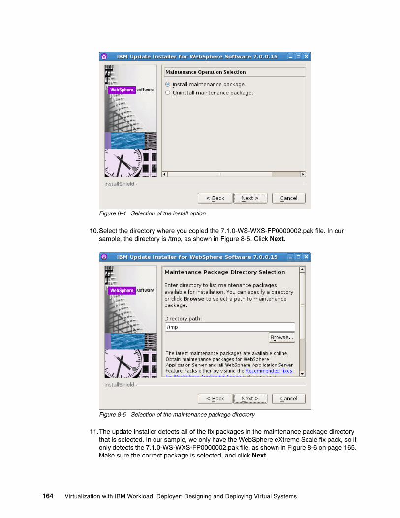
Figure 8-4 Selection of the install option
10.Select the directory where you copied the 7.1.0-WS-WXS-FP0000002.pak file. In our sample, the directory is /tmp, as shown in Figure 8-5. Click Next.
Figure 8-5 Selection of the maintenance package directory
11.The update installer detects all of the fix packages in the maintenance package directory that is selected. In our sample, we only have the WebSphere eXtreme Scale fix pack, so it only detects the 7.1.0-WS-WXS-FP0000002.pak file, as shown in Figure 8-6 on page 165. Make sure the correct package is selected, and click Next.
164 Virtualization with IBM Workload Deployer: Designing and Deploying Virtual Systems

Figure 8-6 Fix pack selection
12.The update installer allows you to check if your user ID has sufficient permissions to install the update. Leave the check box selected, as shown in Figure 8-7, and click Next.
Figure 8-7 User permission check
Chapter 8. Configuring the pre-production system 165

13.If you have sufficient permissions the option allows you to proceed, as shown in Figure 8-8. Click Next to proceed.
Figure 8-8 Permissions’ verification result
14.After the update installer finishes, verify that the installation completed successfully, and then click Finish, as shown in Figure 8-9 on page 167.
166 Virtualization with IBM Workload Deployer: Designing and Deploying Virtual Systems

Figure 8-9 Update installer result
15.Start the Deployment Manager:
/opt/IBM/WebSphere/AppServer/bin/startServer.sh dmgr
When you see the following message, Deployment Manager started:
ADMU30001: Server dmgr open for e-business
16.Log into each virtual image that hosts a custom node and install the Fix Pack. For each system:
a. Log into the virtual system.
b. Verify that the node agent is stopped.
Issue: /opt/IBM/WebSphere/AppServer/bin/serverStatus.sh nodeagent
The following message indicates that the node agent is stopped:
ADMU0509I The Node Agent “nodeagent” cannot be reached. It appears to be stopped.
c. Run the update.sh command to install the fix pack:
/opt/IBM/WebSphere/AppServer/UpdateInstaller/update.sh
d. Start the node agent:
/opt/IBM/WebSphere/AppServer/bin/startServer.sh nodeagent
17.When the installations are complete, log into the Deployment Manager, and select Administration Nodes and ensure that all the nodes have a started status.
8.2.1 Creating a script package for future use
There are multiple methods for handling maintenance installation in virtual images and virtual systems, for example:
� You can install the maintenance manually, as we just did.
� You can clone and extend the image, install the maintenance, and then recapture the image for future use (see 10.5, “Managing images and patterns: Strategic approach” on page 293).
Chapter 8. Configuring the pre-production system 167

� You can install maintenance directly to a virtual system using the IBM Workload Deployer Catalog Emergency Fixes option (see 10.3, “Applying maintenance with IBM Workload Deployer” on page 265).
� You can use Rational Automation Framework for WebSphere to apply the maintenance (see 10.4, “Applying maintenance with Rational Automation Framework for WebSphere” on page 269).
� You can also create a script package, and add it to each part in the pattern so that the Fix Package is installed at deployment.
This section addresses the last option. We created a script package to automate the installation of the fix pack in future deployments of the virtual systems. The script package uses the silent installation option to execute the upgrade of the system. This script package can be added to each part in the pattern where WebSphere eXtreme Scale is installed.
The script package archive contains the following files:
� cbscript.json � serverUpgrade.sh� install.txt� 7.1.0.2-WS-WXS-FP0000002.pak
The cbscript.json is a special JSON object used to populate the information needed by the script package. The content of the cbscript.json file for this package is shown in Example 8-1. It specifies that the serverUpgrade.sh command be executed. At deployment, the serverUpgrade.zip file is extracted in the directory specified in the location filed of the cbscript.json file, so in our example the /tmp/serverUpgrade directory, so all of the files included in the script package are in this directory.
Example 8-1 cbscript.json for the serverUpgrade.zip
{ "name": "serverUpgrade", "version": "1.0.0", "description": "Install the fix pack 7.1.0.2 for WebSphere eXtreme Scale", "command": "/bin/sh /tmp/serverUpgrade/serverUpgrade.sh", "log": "", "location": "/tmp/serverUpgrade", "timeout": "0", "commandargs": "", "keys": [ ]}
The serverUpgrade.sh script, shown in Example 8-2, invokes the WebSphere update installer in silent mode. It first stops the WebSphere processes on the node and then runs the update installer with the -silent option. After the update process is complete, the WebSphere processes are started again.
Example 8-2 serverUpgrade.sh for the serverUpgrade.zip
#!/bin/sh## Script to install the fix pack#source /etc/virtualimage.properties
168 Virtualization with IBM Workload Deployer: Designing and Deploying Virtual Systems

cd /opt/IBM/WebSpherechown -R virtuser:users *chmod -R 775 *
if [ $PROFILE_TYPE == "custom" ] ; then su virtuser -c "$WAS_PROFILE_ROOT/bin/stopNode.sh"elif [ $PROFILE_TYPE == "default" ] ; then su virtuser -c "$WAS_PROFILE_ROOT/bin/stopServer.sh server1"else su virtuser -c "$WAS_PROFILE_ROOT/bin/stopManager.sh"fi
su virtuser -c "/opt/IBM/WebSphere/AppServer/UpdateInstaller/update.sh -silent -options /tmp/serverUpgrade/install.txt”
if [ $PROFILE_TYPE == "custom" ] ; thensu virtuser -c "$WAS_PROFILE_ROOT/bin/startNode.sh"
elif [ $PROFILE_TYPE == "default" ] ; thensu virtuser -c "$WAS_PROFILE_ROOT/bin/startServer.sh server1"
elsesu virtuser -c "$WAS_PROFILE_ROOT/bin/startManager.sh"
fi
You probably noticed that we defined the /etc/virtualimage.properties file as a source for our bash script. This file contains a set of predefined environment variables that can be used. This file is shown in Example 8-3.
Example 8-3 Sample content of the /etc/virtualimage.properties/etc file
CELL_NAME=CloudBurstCell_3VNC_SERVER_URL=http://itso-cb-sys6.itso.ral.ibm.com:5801/JMGR_REGISTER=falseAPP_SERVICE_PACKAGE_LOCATION=/tmp/update/appSERVICE_PACKAGE_LOCATION=/tmp/updateAPP_SERVICE_COMMAND=/opt/IBM/AE/AS/installAppService.shSTART_SERVICES_COMMAND_LOCATION=/opt/IBM/AE/ASWAS_INSTALL_ROOT=/opt/IBM/WebSphere/AppServerPROFILE_NAME=DefaultDmgr01ADMIN_CONSOLE_URL=http://itso-cb-sys6.itso.ral.ibm.com:9060/ibm/consoleSERVICE_COMMAND=/opt/IBM/AE/AS/installService.shHOSTNAME=itso-cb-sys6.itso.ral.ibm.comITM_TEMS_HOSTNAME=itso-cb-sys8.itso.ral.ibm.comAUGMENT_LIST=noneSTOP_SERVICES_COMMAND=/opt/IBM/AE/AS/stopVirtualImageServices.shETHERNET0="VM Network"SERVICE_COMMAND_LOG=/opt/IBM/WebSphere/AppServer/logsWAS_CONTROL_HOME=/opt/IBM/AE/ASRESET_VIRTUAL_IMAGE_COMMAND_LOCATION=/var/adm/ibmvmcoc-postinstallPROFILE_ROOT=/opt/IBM/WebSphere/ProfilesDMGR_FEDERATE=falseDELETE_VIRTUAL_MACHINE=/opt/IBM/AE/AS/removeWASVM.shAPP_SERVICE_COMMAND_LOG=/opt/IBM/WebSphere/AppServer/logsOS_SERVICE_COMMAND=/opt/IBM/AE/AS/installOSService.shAMT_MEM=2075488OPERATION_COMMAND_LOCATION=/opt/IBM/AE/AS
Chapter 8. Configuring the pre-production system 169

OS_SERVICE_COMMAND_LOG=/opt/IBM/WebSphere/AppServer/logsNUM_CPUS=1OPERATION_COMMAND="/opt/IBM/WebSphere/AppServer/bin/ws_ant.sh -f /opt/IBM/AE/AS/wasHVControl.ant"PROFILE_NUMBER=SERVICE_COMMAND_LOCATION=/opt/IBM/AE/ASOS_SERVICE_PACKAGE_LOCATION=/tmp/update/osADVANCED_FEATURE_SELECTED=trueNODE_NAME=CloudBurstNode_3RESET_VIRTUAL_IMAGE_COMMAND=/var/adm/ibmvmcoc-postinstall/resetvm.shSTART_SERVICES_COMMAND=/opt/IBM/AE/AS/startVirtualImageServices.shAUTOSTART=truePROFILE_TYPE=dmgrSTOP_SERVICES_COMMAND_LOCATION=/opt/IBM/AE/ASWAS_PROFILE_ROOT=/opt/IBM/WebSphere/Profiles/DefaultDmgr01
Finally, the install.txt file is the response file you must provide to execute the silent installation. It contains a number of options as the maintenance package directory or the option to define whether or not to check the file permissions. The file for our installation is shown in Example 8-4.
Example 8-4 install.txt response file for the serverUpgrade.zip
-OPT checkFilePermissions="false"-W maintenance.package=/tmp/serverUpgrade/7.1.0-WS-WXS-FP0000002.pak-OPT disableNonBlockingPrereqChecking="true"-W product.location="/opt/IBM/WebSphere/AppServer"-W update.type="install"
8.3 Enabling the log command assistance functionality
Rational Automation Framework for WebSphere natively supports the configuration steps for the WebSphere Application Server cell. We perform the configuration manually using the WebSphere Application Server administrative console and enable a feature in the console that logs the commands as we execute them. To enable this feature:
1. Log into the WebSphere Application Server console, and select System administration Console Preferences, as shown in Figure 8-10.
Figure 8-10 Console preferences option
170 Virtualization with IBM Workload Deployer: Designing and Deploying Virtual Systems

2. Select the following options, as shown in Figure 8-11:
– Enable command assistance notifications– Log command assistance commands
Figure 8-11 Enable the log command assistance
You can optionally select also the Synchronize changes with Nodes option to have the configuration synchronized automatically after each configuration change.
3. Select Apply to apply the changes.
4. The command assistance logs are saved under the Deployment Manager logs directory, as shown in Figure 8-12.
Figure 8-12 Deployment manager logs directory content
The output of the command assistance is similar to the sample shown in Example 8-5. It contains the wsadmin commands required to execute the same configuration tasks that you performed in the console.
Example 8-5 Sample command assistant log
# [6/13/11 20:05:24:287 UTC] ApplicationServer
Chapter 8. Configuring the pre-production system 171
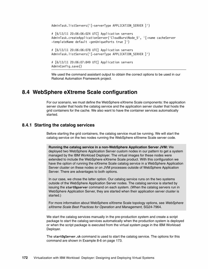
AdminTask.listServers('[-serverType APPLICATION_SERVER ]')
# [6/13/11 20:06:06:024 UTC] Application serversAdminTask.createApplicationServer('CloudBurstNode_5', '[-name cacheServer -templateName default -genUniquePorts true ]')
# [6/13/11 20:06:06:078 UTC] Application serversAdminTask.listServers('[-serverType APPLICATION_SERVER ]')
# [6/13/11 20:06:07:849 UTC] Application serversAdminConfig.save()
We used the command assistant output to obtain the correct options to be used in our Rational Automation Framework project.
8.4 WebSphere eXtreme Scale configuration
For our scenario, we must define the WebSphere eXtreme Scale components: the application server cluster that hosts the catalog service and the application server cluster that hosts the grid containers for the cache. We also want to have the container services automatically started.
8.4.1 Starting the catalog services
Before starting the grid containers, the catalog service must be running. We will start the catalog service on the two nodes running the WebSphere eXtreme Scale server code.
We start the catalog services manually in the pre-production system and create a script package to start the catalog services automatically when the production system is deployed or when the script package is executed from the virtual system page in the IBM Workload Deployer.
The startOgServer.sh command is used to start the catalog service. The options for this command are shown in Example 8-6 on page 173.
Running the catalog service in a non-WebSphere Application Server JVM: We deployed two WebSphere Application Server custom nodes in our pattern to get a system managed by the IBM Workload Deployer. The virtual images for these nodes were extended to include the WebSphere eXtreme Scale product. With this configuration we have the option of running the eXtreme Scale catalog service in a WebSphere Application Server cluster on these nodes or on JVM processes outside of WebSphere Application Server. There are advantages to both options.
In our case, we chose the latter option. Our catalog service runs on the two systems outside of the WebSphere Application Server nodes. The catalog service is started by issuing the startOgserver command on each system. (When the catalog servers run in WebSphere Application Server, they are started when their application server cluster is started.)
For more information about WebSphere eXtreme Scale topology options, see WebSphere eXtreme Scale Best Practices for Operation and Management, SG24-7964.
172 Virtualization with IBM Workload Deployer: Designing and Deploying Virtual Systems

Example 8-6 startOgServer.sh options
To start an eXtreme Scale catalog service process: <server> [options]To start an eXtreme Scale container server: <server> -objectgridFile <xml file> [options] <server> -objectgridUrl <xml URL> [options]Catalog service options: -catalogServiceEndPoints <server:host:port:port,server:host:port:port> -quorum true|false -heartbeat 0|1|-1 -clusterSecurityFile <cluster security xml file> -clusterSecurityUrl <cluster security xml URL> -domain <domain name>Container server options: -catalogServiceEndPoints <host:port,host:port> -deploymentPolicyFile <deployment policy xml file> -deploymentPolicyUrl <deployment policy xml URL> -haManagerPort <port> -zone <zoneName>Common options: -listenerHost <hostname> -listenerPort <port> -serverProps <server properties file> -JMXServicePort <port> -traceSpec <trace specification> -traceFile <trace file> -timeout <seconds> -script <script file> -jvmArgs <JVM arguments>
To start the catalog services we run the following commands:
� On node itso-cb-sys1.itso.ral.ibm.com:
– /opt/IBM/WebSphere/AppServer/bin/startOgServer.sh cs1 -catalogServiceEndPoints cs1:itso-cb-sys1.itso.ral.ibm.com:6670:6671,cs2:itso-cb-sys2.itso.ral.ibm.com:6770:6771 -listenerPort 6672 -JMXServicePort 6673 -jvmArgs -Xms256M -Xmx512M
� On node itso-cb-sys2.itso.ral.ibm.com:
– /opt/IBM/WebSphere/AppServer/bin/startOgServer.sh cs2 -catalogServiceEndPoints cs1:itso-cb-sys1.itso.ral.ibm.com:6670:6671,cs2:itso-cb-sys2.itso.ral.ibm.com:6770:6771 -listenerPort 6772 -JMXServicePort 6773 -jvmArgs -Xms256M -Xmx512M
The catalog service does not start until both of the catalog services are started. You can check if the catalog services cs1 and cs2 are started by looking at the sysout.log files for each server and searching for the following command:
CWOBJ1001I: ObjectGrid Server server_name is ready to process requests
Example 8-7 on page 174 shows the system out log for the server on itso-cb-sys1.itso.ral.ibm.com where catalog server cs1 has been started.
Chapter 8. Configuring the pre-production system 173
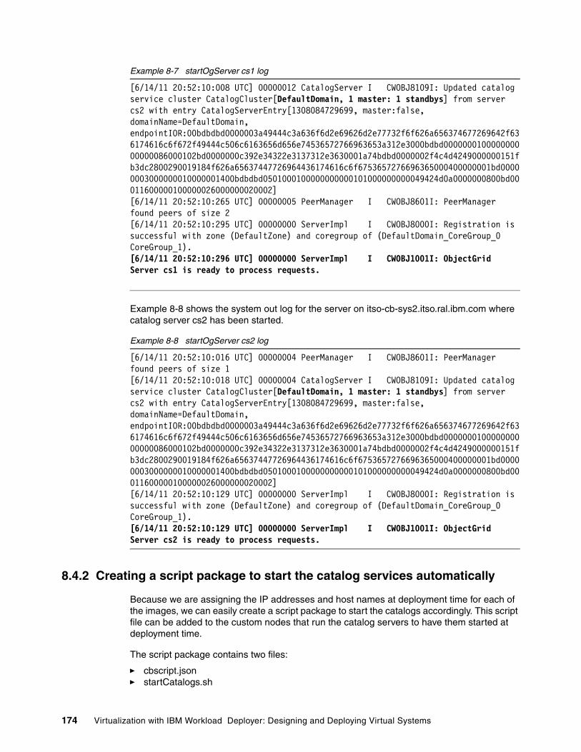
Example 8-7 startOgServer cs1 log
[6/14/11 20:52:10:008 UTC] 00000012 CatalogServer I CWOBJ8109I: Updated catalog service cluster CatalogCluster[DefaultDomain, 1 master: 1 standbys] from server cs2 with entry CatalogServerEntry[1308084729699, master:false, domainName=DefaultDomain, endpointIOR:00bdbdbd0000003a49444c3a636f6d2e69626d2e77732f6f626a656374677269642f636174616c6f672f49444c506c6163656d656e74536572766963653a312e3000bdbd000000010000000000000086000102bd0000000c392e34322e3137312e3630001a74bdbd0000002f4c4d4249000000151fb3dc2800290019184f626a65637447726964436174616c6f6753657276696365000400000001bd00000003000000010000001400bdbdbd0501000100000000000101000000000049424d0a0000000800bd00011600000100000026000000020002][6/14/11 20:52:10:265 UTC] 00000005 PeerManager I CWOBJ8601I: PeerManager found peers of size 2[6/14/11 20:52:10:295 UTC] 00000000 ServerImpl I CWOBJ8000I: Registration is successful with zone (DefaultZone) and coregroup of (DefaultDomain_CoreGroup_0 CoreGroup_1).[6/14/11 20:52:10:296 UTC] 00000000 ServerImpl I CWOBJ1001I: ObjectGrid Server cs1 is ready to process requests.
Example 8-8 shows the system out log for the server on itso-cb-sys2.itso.ral.ibm.com where catalog server cs2 has been started.
Example 8-8 startOgServer cs2 log
[6/14/11 20:52:10:016 UTC] 00000004 PeerManager I CWOBJ8601I: PeerManager found peers of size 1[6/14/11 20:52:10:018 UTC] 00000004 CatalogServer I CWOBJ8109I: Updated catalog service cluster CatalogCluster[DefaultDomain, 1 master: 1 standbys] from server cs2 with entry CatalogServerEntry[1308084729699, master:false, domainName=DefaultDomain, endpointIOR:00bdbdbd0000003a49444c3a636f6d2e69626d2e77732f6f626a656374677269642f636174616c6f672f49444c506c6163656d656e74536572766963653a312e3000bdbd000000010000000000000086000102bd0000000c392e34322e3137312e3630001a74bdbd0000002f4c4d4249000000151fb3dc2800290019184f626a65637447726964436174616c6f6753657276696365000400000001bd00000003000000010000001400bdbdbd0501000100000000000101000000000049424d0a0000000800bd00011600000100000026000000020002][6/14/11 20:52:10:129 UTC] 00000000 ServerImpl I CWOBJ8000I: Registration is successful with zone (DefaultZone) and coregroup of (DefaultDomain_CoreGroup_0 CoreGroup_1).[6/14/11 20:52:10:129 UTC] 00000000 ServerImpl I CWOBJ1001I: ObjectGrid Server cs2 is ready to process requests.
8.4.2 Creating a script package to start the catalog services automatically
Because we are assigning the IP addresses and host names at deployment time for each of the images, we can easily create a script package to start the catalogs accordingly. This script file can be added to the custom nodes that run the catalog servers to have them started at deployment time.
The script package contains two files:
� cbscript.json� startCatalogs.sh
174 Virtualization with IBM Workload Deployer: Designing and Deploying Virtual Systems

The cbscript.json is a special JSON object used to populate the information needed by the script package. The content of the cbscript.json for this package is shown in Example 8-9.
Example 8-9 cbscript.json for the startCatalogs script package
{ "name": "Start catalog services", "version": "1.0.0", "description": "This script starts the catlalog services on each of the two custom node with WXS", "command": "/bin/sh /tmp/startCatalogs/startCatalogs.sh", "log": "/tmp/wxsAugment/startCatalogs.traceout", "location": "/tmp/startCatalogs", "timeout": "0", "commandargs": "", "keys": [ ]}
The Bash script that starts the catalog services is a simple one. Because we define the IP addresses and host names of the virtual machines at deployment time, we can check the host names of the server where the script is running and start the appropriate catalog server. If the host name of the system is itso-cb-sys1.itso.ral.ibm.com, the script will start the catalog server referred to as cs1. Otherwise, the assumption is that the script is running on itso-cb-sys2.itso.ral.ibm.com and the catalog referred to as cs2 is started.
The script is shown in Example 8-10.
Example 8-10 startCatalogs.sh script
#!/bin/sh#
source /etc/virtualimage.properties
if [ $HOSTNAME == "itso-cb-sys1.itso.ral.ibm.com" ] ; thensu virtuser -c "/opt/IBM/WebSphere/AppServer/bin/startOgServer.sh cs1 -catalogServiceEndPoints cs1:itso-cb-sys1.itso.ral.ibm.com:6670:6671,cs2:itso-cb-sys2.itso.ral.ibm.com:6770:6771 -listenerPort 6672 -JMXServicePort 6673 -jvmArgs -Xms256M -Xmx512M"elsesu virtuser -c "/opt/IBM/WebSphere/AppServer/bin/startOgServer.sh cs2 -catalogServiceEndPoints cs1:itso-cb-sys1.itso.ral.ibm.com:6670:6671,cs2:itso-cb-sys2.itso.ral.ibm.com:6770:6771 -listenerPort 6772 -JMXServicePort 6773 -jvmArgs -Xms256M -Xmx512M"fi
Note: It is possible to generalize the script referencing these properties in your script package by using the syntax ${part-name.property-name}. For more information, see the Properties variable syntax topic in the IBM Workload Deployer Information Center at:
http://publib.boulder.ibm.com/infocenter/worlodep/v3r0m0/topic/com.ibm.worlodep.doc/pc/pcc_part_properties.html
Chapter 8. Configuring the pre-production system 175

8.4.3 Configuring the catalog service domain
In this step, we configure the catalog service domain using the administrative console and capture the wsadmin commands for use in a script.
1. In the WebSphere Application Server console, navigate to System administration WebSphere eXtreme Scale Catalog service domains, as shown in Figure 8-13.
Figure 8-13 Catalog service domain configuration
2. In the catalog service domains definition page, click New to add a new catalog service domain.
3. Fill in the required information, as shown in Figure 8-14:
a. The name of the catalog service domain name is ITSOCatalogCluster.
b. The catalog server can run on the Deployment Manager (the process local to the administrative console), another process in the cell, or on a server outside of the cell. In this case, we are running the catalog servers in a stand alone server outside of the WebSphere cell. Select Remote server, and provide the host name of the first server where you started the catalog service. In our sample, it is itso-cb-sys1.itso.ral.ibm.com.
c. Provide the Listener Port for that catalog service. In our sample, it is 6672 (this port matches the -listenerPort option on the startOgServer command).
Figure 8-14 Catalog service cluster definition Part 1
4. Click New to add a second catalog server entry, as shown in Figure 8-15 on page 177.
176 Virtualization with IBM Workload Deployer: Designing and Deploying Virtual Systems

Figure 8-15 Add a second catalog server to the domain
5. Add the information required, as shown in Figure 8-16:
a. Select Remote server, and provide the host name of the second server where you started the catalog service. In our sample, it is itso-cb-sys2.itso.ral.ibm.com.
b. Provide the Listener Port for that catalog service. In our, it is sample 6772.
Figure 8-16 Catalog servers defined
6. Click OK, and save the changes. Because we previously selected the console preferences setting to synchronize the changes with the nodes automatically, the synchronization takes place at this time. The synchronization ends when you see the following message (Figure 8-17 on page 178):
The configuration synchronization is complete for the cell
Wait until the process completes, and click OK.
Chapter 8. Configuring the pre-production system 177

Figure 8-17 Synchronization completed
7. Because the two catalog servers are already started, if you go to System administration WebSphere eXtreme Scale Catalog service domains, and select the link for the ITSOCatalogCluster domain, the console shows both of the catalog servers with a started status, as shown in Figure 8-18.
Figure 8-18 Catalog servers started
8. You can also test the connection by clicking Test connection. If the catalog servers are active and reachable, you will receive the message in Figure 8-19.
Figure 8-19 Connection test completed successfully
8.5 Creating and configuring the cluster for the grid containers
We create a cluster to host our grid containers. This cluster is created on the two custom nodes extended with the WebSphere eXtreme Scale server software. These are the same systems where the catalog service JVMs will run. To have the servers act as containers, we must provide two configuration files. Both of these steps are discussed in this section.
Note: If you run the catalog service within a WebSphere process, you must install the interim fix 7.1.0.2-WS-WXS-IFPM37461.
178 Virtualization with IBM Workload Deployer: Designing and Deploying Virtual Systems

8.5.1 Creating the cluster
We first create a cluster of grid containers to host our cache using the following steps:
1. Before you create the cluster, identify which nodes are the WebSphere eXtreme Scale nodes but do not have the Intelligent Management Pack.
In the WebSphere administrative console, select System administration Nodes to obtain a list of all the nodes in the cell. The list will look like Figure 8-20.
The images with WXS 7.1.0.2 in the Version column, but without WXDOP (the Intelligent Management Pack), are the images that we want to use. They are highlighted in Figure 8-20.
Figure 8-20 WebSphere eXtreme Scale servers
2. Now that we have identified the nodes, select Servers Clusters, and click WebSphere application sever clusters, as shown in Figure 8-21.
Figure 8-21 Server menu
3. Click New to create a new WebSphere application sever cluster.
Chapter 8. Configuring the pre-production system 179

4. Type the cluster name. In our sample, we use ITSOCacheCluster as the cluster name, as shown in Figure 8-22, and click Next.
Figure 8-22 Cluster ITSOCacheCluster Step 1
5. Provide the first cluster member name, and select one of the two nodes. In our sample, we defined the member name as ITSOCache, as shown in Figure 8-23. Leave the default options for all of the other configurations, and click Next.
Figure 8-23 First cluster member definition
6. Define the second cluster member ITSOCache_1 (to match the naming convention used for the nodes). Select the second node, and click Add Member, as shown in Figure 8-24 on page 181. Click Next.
180 Virtualization with IBM Workload Deployer: Designing and Deploying Virtual Systems

Figure 8-24 Second cluster member definition
The console should look like Figure 8-25.
Figure 8-25 Cluster members
7. Click Finish, and save the configuration.
8.5.2 Configuring the grid
To start the WebSphere eXtreme Scale containers automatically, we deploy an application on the cluster that contains the WebSphere eXtreme Scale configuration files. WebSphere eXtreme Scale monitors all the applications installed, and if a module with the WebSphere eXtreme Scale XML file is detected, it registers the application server as a container process to the catalog service.
We created a simple EAR file (you can create also a WAR file if you prefer) that contains, in the META-INF of the WebContent directory, the following files, shown in Figure 8-26:
� objectGrid.xml� objectGridDeployment.xml
Figure 8-26 Content of the WebContent’s META-INF directory
Chapter 8. Configuring the pre-production system 181

Those files are provided by IBM, and you can find them in the WebSphere eXtreme Scale installation directory, as shown in Figure 8-27.
/opt/IBM/WebSphere/AppServer/optionalLibraries/ObjectGrid/session/samples
Figure 8-27 Content of the directory <WAS_HOME>/optionalLibreries/ObjectGird/session/samples
The directory includes five XML files and a splicer.properties file.
WebSphere eXtreme Scale can be configured in a co-located topology or in a remote topology. Co-located means that the application and the grid both run in the same JVM. Remote means that the application and grid run in separate JVMs, which is the case in our scenario.
To use the co-located topology, use the following configuration files:
� objectGridDeployment.xml� objectGrid.xml
To use the remote topology, as is our case, use the following configuration files:
� objectGridDeploymentStandAlone.xml� objectGridStandAlone.xml
Example 8-11 shows the newly named objectGrid.xml configuration file. We use this file as is (no changes).
Example 8-11 objectGrid.xml
<?xml version="1.0" encoding="UTF-8"?><objectGridConfig xmlns:xsi="http://www.w3.org/2001/XMLSchema-instance" xsi:schemaLocation="http://ibm.com/ws/objectgrid/config ../objectGrid.xsd" xmlns="http://ibm.com/ws/objectgrid/config">
<objectGrids><objectGrid name="session">
<bean id="ObjectGridEventListener" className="com.ibm.ws.xs.sessionmanager.SessionHandleManager"/> <backingMap name="objectgridSessionMetadata" pluginCollectionRef="objectgridSessionMetadata" readOnly="false" lockStrategy="PESSIMISTIC" ttlEvictorType="LAST_ACCESS_TIME" timeToLive="3600" copyMode="COPY_TO_BYTES"/> <backingMap name="objectgridSessionAttribute.*" template="true" readOnly="false" lockStrategy="PESSIMISTIC" ttlEvictorType="NONE" copyMode="COPY_TO_BYTES"/>
Attention! The deployed file names must be objectGridDeployment.xml and objectGrid.xml, so when using the configuration files for the remote topology you must change the names from objectGridDeploymentStandAlone.xml to objectGridDeployment.xml and from objectGridStandAlone.xml to objectGrid.xml
182 Virtualization with IBM Workload Deployer: Designing and Deploying Virtual Systems
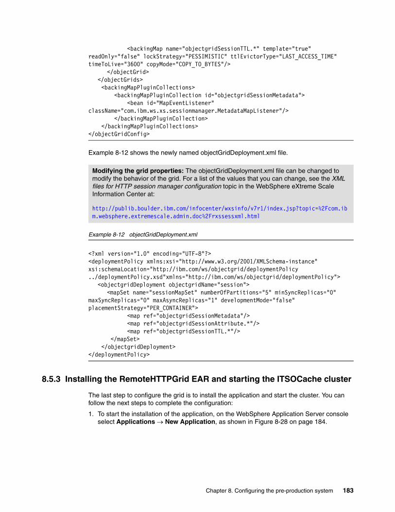
<backingMap name="objectgridSessionTTL.*" template="true" readOnly="false" lockStrategy="PESSIMISTIC" ttlEvictorType="LAST_ACCESS_TIME" timeToLive="3600" copyMode="COPY_TO_BYTES"/>
</objectGrid></objectGrids>
<backingMapPluginCollections> <backingMapPluginCollection id="objectgridSessionMetadata"> <bean id="MapEventListener" className="com.ibm.ws.xs.sessionmanager.MetadataMapListener"/> </backingMapPluginCollection> </backingMapPluginCollections></objectGridConfig>
Example 8-12 shows the newly named objectGridDeployment.xml file.
Example 8-12 objectGridDeployment.xml
<?xml version="1.0" encoding="UTF-8"?><deploymentPolicy xmlns:xsi="http://www.w3.org/2001/XMLSchema-instance" xsi:schemaLocation="http://ibm.com/ws/objectgrid/deploymentPolicy ../deploymentPolicy.xsd"xmlns="http://ibm.com/ws/objectgrid/deploymentPolicy">
<objectgridDeployment objectgridName="session"><mapSet name="sessionMapSet" numberOfPartitions="5" minSyncReplicas="0"
maxSyncReplicas="0" maxAsyncReplicas="1" developmentMode="false" placementStrategy="PER_CONTAINER"> <map ref="objectgridSessionMetadata"/> <map ref="objectgridSessionAttribute.*"/> <map ref="objectgridSessionTTL.*"/>
</mapSet> </objectgridDeployment></deploymentPolicy>
8.5.3 Installing the RemoteHTTPGrid EAR and starting the ITSOCache cluster
The last step to configure the grid is to install the application and start the cluster. You can follow the next steps to complete the configuration:
1. To start the installation of the application, on the WebSphere Application Server console select Applications New Application, as shown in Figure 8-28 on page 184.
Modifying the grid properties: The objectGridDeployment.xml file can be changed to modify the behavior of the grid. For a list of the values that you can change, see the XML files for HTTP session manager configuration topic in the WebSphere eXtreme Scale Information Center at:
http://publib.boulder.ibm.com/infocenter/wxsinfo/v7r1/index.jsp?topic=%2Fcom.ibm.websphere.extremescale.admin.doc%2Frxssessxml.html
Chapter 8. Configuring the pre-production system 183
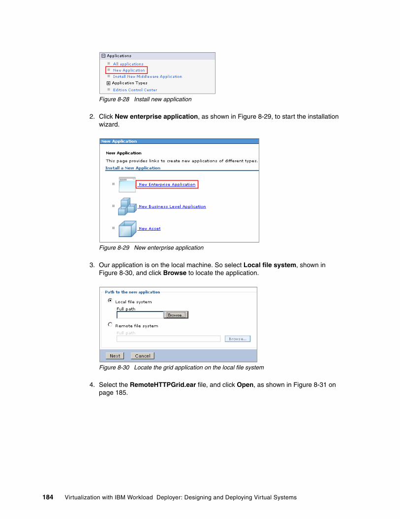
Figure 8-28 Install new application
2. Click New enterprise application, as shown in Figure 8-29, to start the installation wizard.
Figure 8-29 New enterprise application
3. Our application is on the local machine. So select Local file system, shown in Figure 8-30, and click Browse to locate the application.
Figure 8-30 Locate the grid application on the local file system
4. Select the RemoteHTTPGrid.ear file, and click Open, as shown in Figure 8-31 on page 185.
184 Virtualization with IBM Workload Deployer: Designing and Deploying Virtual Systems

Figure 8-31 RemoteHTTPGrid EAR selection
5. The console should look like in Figure 8-32. Click Next to continue the installation procedure.
Figure 8-32 The EAR file is now selected
6. Select the Fast Path option for the installation, as shown in Figure 8-33, and click Next.
Figure 8-33 Fast path installation
Chapter 8. Configuring the pre-production system 185

7. In Step 1 (Select installation options, shown in Figure 8-34 on page 186), leave the default values.
You can provide an application edition number and edition description. This is because the Deployment Manager profile is also augmented with the Intelligent Management Pack containing the WebSphere Virtual Enterprise function.
Click Next to proceed with the installation.
Figure 8-34 Select installation option for RemoteHTTPGrid EAR
8. Map the application on the ITSOCacheCluster, as shown in Figure 8-35:
a. Check the box to the left of the application.b. Select the cluster in the list of clusters and servers.c. Click Apply.d. Click Next to continue.
Figure 8-35 Map the application on the ITSOCacheCluster
9. Accept the default virtual host mapping, and click Next.
10.Click Finish to complete the installation.
11.Save the configuration.
12.You can now start the cluster. Select Servers Clusters WebSphere application server clusters.
186 Virtualization with IBM Workload Deployer: Designing and Deploying Virtual Systems
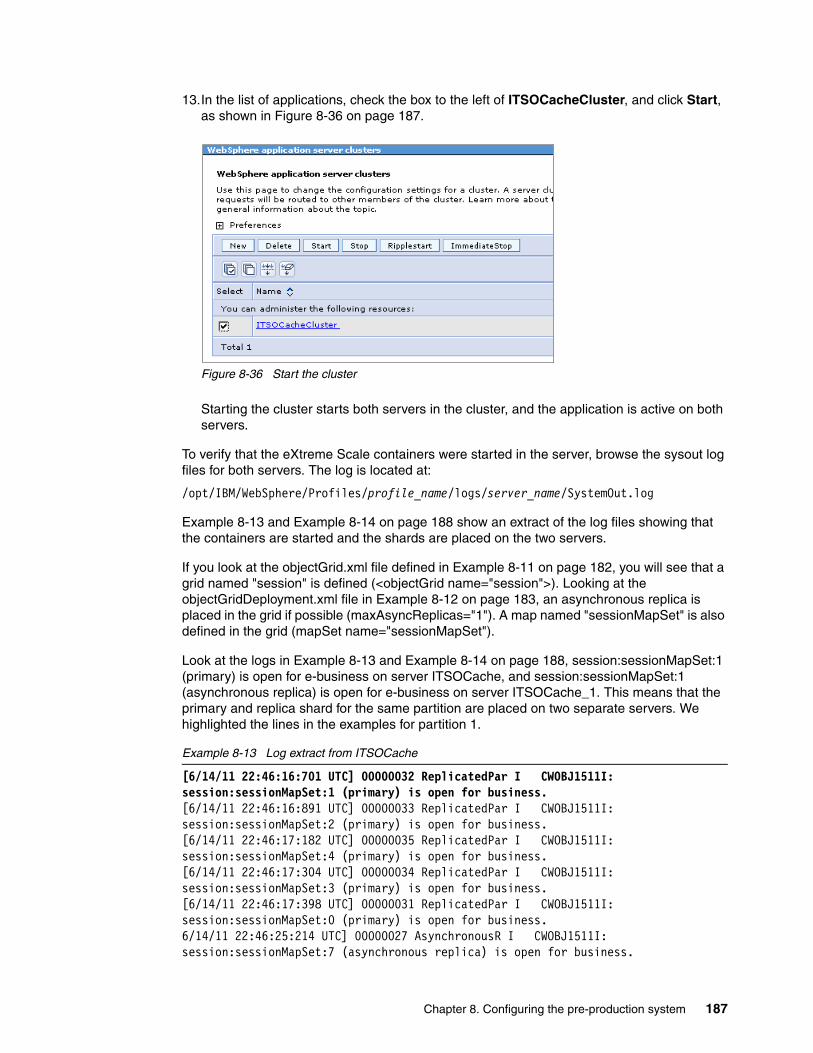
13.In the list of applications, check the box to the left of ITSOCacheCluster, and click Start, as shown in Figure 8-36 on page 187.
Figure 8-36 Start the cluster
Starting the cluster starts both servers in the cluster, and the application is active on both servers.
To verify that the eXtreme Scale containers were started in the server, browse the sysout log files for both servers. The log is located at:
/opt/IBM/WebSphere/Profiles/profile_name/logs/server_name/SystemOut.log
Example 8-13 and Example 8-14 on page 188 show an extract of the log files showing that the containers are started and the shards are placed on the two servers.
If you look at the objectGrid.xml file defined in Example 8-11 on page 182, you will see that a grid named "session" is defined (<objectGrid name="session">). Looking at the objectGridDeployment.xml file in Example 8-12 on page 183, an asynchronous replica is placed in the grid if possible (maxAsyncReplicas="1"). A map named "sessionMapSet" is also defined in the grid (mapSet name="sessionMapSet").
Look at the logs in Example 8-13 and Example 8-14 on page 188, session:sessionMapSet:1 (primary) is open for e-business on server ITSOCache, and session:sessionMapSet:1 (asynchronous replica) is open for e-business on server ITSOCache_1. This means that the primary and replica shard for the same partition are placed on two separate servers. We highlighted the lines in the examples for partition 1.
Example 8-13 Log extract from ITSOCache
[6/14/11 22:46:16:701 UTC] 00000032 ReplicatedPar I CWOBJ1511I: session:sessionMapSet:1 (primary) is open for business.[6/14/11 22:46:16:891 UTC] 00000033 ReplicatedPar I CWOBJ1511I: session:sessionMapSet:2 (primary) is open for business.[6/14/11 22:46:17:182 UTC] 00000035 ReplicatedPar I CWOBJ1511I: session:sessionMapSet:4 (primary) is open for business.[6/14/11 22:46:17:304 UTC] 00000034 ReplicatedPar I CWOBJ1511I: session:sessionMapSet:3 (primary) is open for business.[6/14/11 22:46:17:398 UTC] 00000031 ReplicatedPar I CWOBJ1511I: session:sessionMapSet:0 (primary) is open for business.6/14/11 22:46:25:214 UTC] 00000027 AsynchronousR I CWOBJ1511I: session:sessionMapSet:7 (asynchronous replica) is open for business.
Chapter 8. Configuring the pre-production system 187

[6/14/11 22:46:25:226 UTC] 00000029 AsynchronousR I CWOBJ1511I: session:sessionMapSet:5 (asynchronous replica) is open for business.6/14/11 22:46:25:232 UTC] 00000029 AsynchronousR I CWOBJ1511I: session:sessionMapSet:9 (asynchronous replica) is open for business.[6/14/11 22:46:25:471 UTC] 0000003e AsynchronousR I CWOBJ1511I: session:sessionMapSet:8 (asynchronous replica) is open for business.[6/14/11 22:46:25:479 UTC] 00000027 AsynchronousR I CWOBJ1511I: session:sessionMapSet:6 (asynchronous replica) is open for business.
Example 8-14 Log extract from ITSOCache_1
[6/14/11 22:46:24:316 UTC] 00000026 ReplicatedPar I CWOBJ1511I: session:sessionMapSet:6 (primary) is open for business.[6/14/11 22:46:24:354 UTC] 00000028 ReplicatedPar I CWOBJ1511I: session:sessionMapSet:8 (primary) is open for business.[6/14/11 22:46:24:393 UTC] 00000029 ReplicatedPar I CWOBJ1511I: session:sessionMapSet:9 (primary) is open for business.[6/14/11 22:46:24:430 UTC] 00000025 ReplicatedPar I CWOBJ1511I: session:sessionMapSet:5 (primary) is open for business.[6/14/11 22:46:24:455 UTC] 00000027 ReplicatedPar I CWOBJ1511I: session:sessionMapSet:7 (primary) is open for business.[6/14/11 22:46:25:730 UTC] 0000003a AsynchronousR I CWOBJ1511I: session:sessionMapSet:1 (asynchronous replica) is open for business.[6/14/11 22:46:25:766 UTC] 0000003a AsynchronousR I CWOBJ1511I: session:sessionMapSet:3 (asynchronous replica) is open for business.[6/14/11 22:46:25:904 UTC] 0000003b AsynchronousR I CWOBJ1511I: session:sessionMapSet:2 (asynchronous replica) is open for business.[6/14/11 22:46:26:225 UTC] 00000023 AsynchronousR I CWOBJ1511I: session:sessionMapSet:4 (asynchronous replica) is open for business.[6/14/11 22:46:26:335 UTC] 0000003b AsynchronousR I CWOBJ1511I: session:sessionMapSet:0 (asynchronous replica) is open for business.
You can also run the /opt/IBM/WebSphere/AppServer/bin/xsadmin.sh command, included with WebSphere eXtreme Scale, to check the container status. Example 8-15 shows the output of the xsadmin command run against one of the catalog servers.
Example 8-15 xsadmin command result for containers status
[virtuser@itso-cb-sys1 bin]$ ./xsadmin.sh -containers -p 6673
This Administrative Utility is provided as a sample only and is not to beconsidered a fully supported component of the WebSphere eXtreme Scale product
Connecting to Catalog service at localhost:6673
*** Show all online containers for grid - session & mapset - sessionMapSetHost: itso-cb-sys2.itso.ral.ibm.com Container: CloudBurstCell_1\CloudBurstNode_9\ITSOCache_C-2, Server:CloudBurstCell_1\CloudBurstNode_9\ITSOCache, Zone:DefaultZone Partition Shard Type Reserved 5 AsynchronousReplica false 6 AsynchronousReplica false 7 AsynchronousReplica false 8 AsynchronousReplica false
188 Virtualization with IBM Workload Deployer: Designing and Deploying Virtual Systems

9 AsynchronousReplica false 0 Primary false 1 Primary false 2 Primary false 3 Primary false 4 Primary false
Host: itso-cb-sys1.itso.ral.ibm.com Container: CloudBurstCell_1\CloudBurstNode_9_1\ITSOCache_1_C-1, Server:CloudBurstCell_1\CloudBurstNode_9_1\ITSOCache_1, Zone:DefaultZone Partition Shard Type Reserved 0 AsynchronousReplica false 1 AsynchronousReplica false 2 AsynchronousReplica false 3 AsynchronousReplica false 4 AsynchronousReplica false 5 Primary false 6 Primary false 7 Primary false 8 Primary false 9 Primary false
Num containers matching = 2 Total known containers = 2 Total known hosts = 2
8.6 Deploying the business application and configuring the session persistence
The last configuration step creates the dynamic cluster and installs the sample application. After the cluster is created and the application deployed, we run a few test to verify that everything is working properly.
8.6.1 Creating the dynamic cluster
To create the dynamic cluster follow:
1. Verify which node the ODR is running on. If you do not know which node the ODR is running on, you can look in the administrative console to find this information. Select Servers All Servers and look for the ODR. In the example shown in Figure 8-37, the server is on node CloudBurstNode_11.
Figure 8-37 Check the On Demand Router Node
2. You can start creating the dynamic cluster. From the WebSphere Application Server console, navigate to Servers Clusters Dynamic clusters, as shown in Figure 8-38 on page 190.
Chapter 8. Configuring the pre-production system 189

Figure 8-38 Dynamic cluster
3. In the panel, click New to start the creation wizard.
4. Select WebSphere application server from the drop-down menu for the server type selection, as shown in Figure 8-39. Click Next to proceed.
Figure 8-39 Selection of WebSphere application sever as the server type
5. Provide the dynamic cluster name. In our sample, we used ITSOdynCluster, as shown in Figure 8-40 on page 191, and click Next.
190 Virtualization with IBM Workload Deployer: Designing and Deploying Virtual Systems

Figure 8-40 Dynamic cluster name
6. In the dynamic cluster member definition panel, click Preview membership, shown in Figure 8-41, to see which nodes are included by default.
Figure 8-41 Preview membership
7. By default all the nodes with the Intelligent Management Pack are included in the membership policy, shown in Figure 8-42 on page 192. Click Close to go back to the membership policy.
Chapter 8. Configuring the pre-production system 191

Figure 8-42 Node included in the default policy
8. We want to exclude the ODR on CloudBurstNode_11. Click Subexpression builder, shown in Figure 8-43, to open the subexpression builder wizard.
Figure 8-43 Subexpression builder
The subexpression builder provides you two ways to define the nodes to include in the dynamic cluster:
– We can state the nodes that we want to exclude (in our sample CloudBurstNode_11).
– We can state the nodes that we want to include (in our sample CloudBurstNode_3 and CloudBurstNode_3_1).
We decided to use the second option, stating the nodes we want to include (dynClustNode and dynClustNode_1).
9. On the wizard, select:
– And for the Logical operator
– Node name for the Select operand
– Like (LIKE) for the Operator
– Type CloudBurstNode_3* as the Value. This includes both of the nodes starting with CloudBurstNode_3.
192 Virtualization with IBM Workload Deployer: Designing and Deploying Virtual Systems

These settings are shown in Figure 8-44. Click Generate subexpression.
Figure 8-44 Subexpression builder
10.The subexpression is generated. You can see the expression in the Subexpression field at the bottom of the wizard, as shown in Figure 8-45. Click Append, and then Close to exit from the wizard.
Figure 8-45 Subexpression generated
The subexpression is appended to the membership policy.
11.If you click Preview membership, the membership policy now includes only the two nodes desired, as shown in Figure 8-46. Click Close to return to the wizard. Click Next to proceed.
Figure 8-46 Preview of the new membership policy
12.Leave the default options for the dynamic cluster template, shown in Figure 8-47 on page 194, and click Next.
Chapter 8. Configuring the pre-production system 193

Figure 8-47 Template selection
13.Leave the default options for the dynamic cluster specific properties, shown in Figure 8-48, and click Next.
Figure 8-48 Dynamic cluster properties
194 Virtualization with IBM Workload Deployer: Designing and Deploying Virtual Systems

14.Click Finish, as shown in Figure 8-49, and save the changes.
Figure 8-49 Create the dynamic cluster
15.If you navigate to Servers Clusters Dynamic clusters, you will see the new dynamic cluster, as shown in Figure 8-50. Do not start the cluster at this time.
Figure 8-50 Dynamic cluster defined
8.6.2 Installing the sample application
Now that we have the target for the application deployment, we can install the sample application using these steps:
1. In the WebSphere administrative console, select Applications New application, as shown in Figure 8-51 on page 196.
Chapter 8. Configuring the pre-production system 195
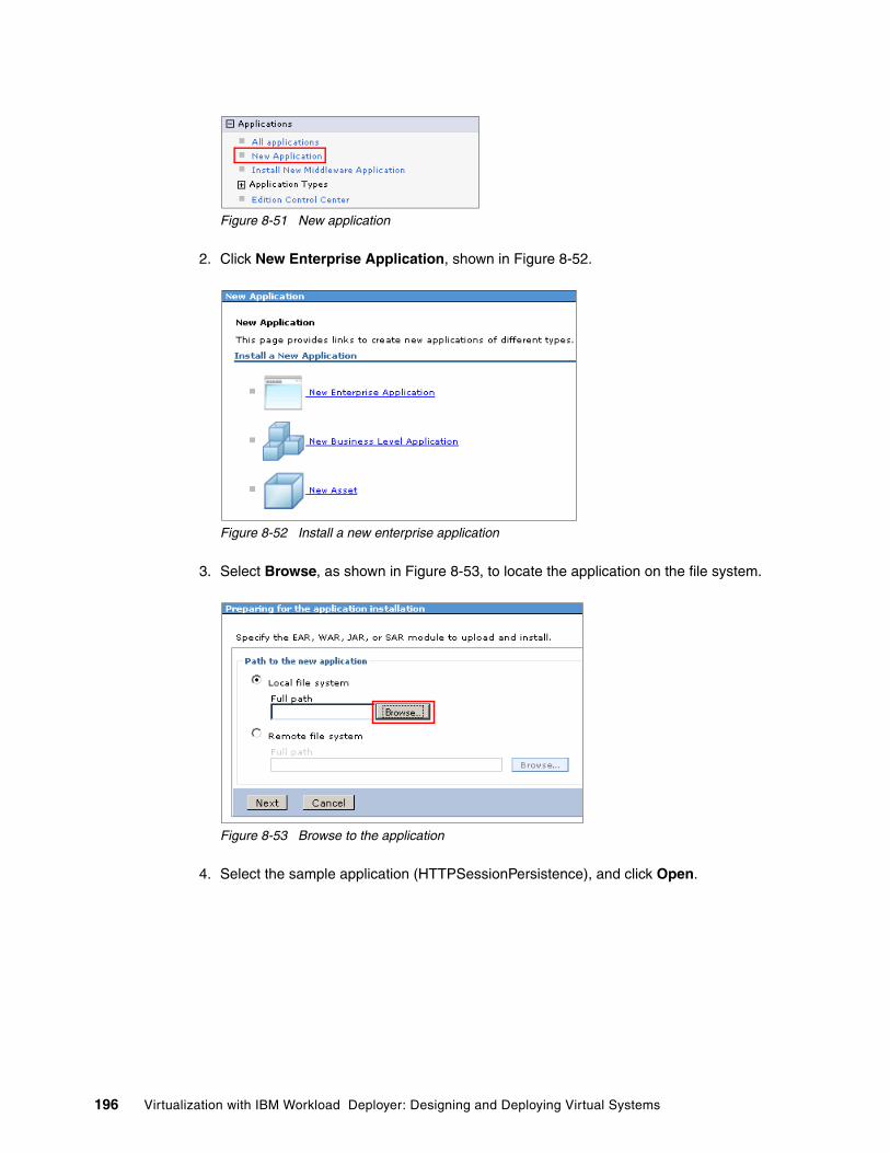
Figure 8-51 New application
2. Click New Enterprise Application, shown in Figure 8-52.
Figure 8-52 Install a new enterprise application
3. Select Browse, as shown in Figure 8-53, to locate the application on the file system.
Figure 8-53 Browse to the application
4. Select the sample application (HTTPSessionPersistence), and click Open.
196 Virtualization with IBM Workload Deployer: Designing and Deploying Virtual Systems

Figure 8-54 Select the sample application
5. Click Next to proceed with the wizard.
6. Select the Fast Path option to install the application.
7. On the next panel, leave the application edition field, Figure 8-55, blank, and click Next.
Prior to WebSphere eXtreme Scale 7.1.0.4 there is an issue with using HTTP session persistence with WebSphere eXtreme Scale and using application edition numbers. If you are above this maintenance level, you can add the application edition numbers.
Figure 8-55 Step 1 of the installation wizard
8. Map the application to the dynamic cluster by checking the box to the left of the application module, Figure 8-56, and then clicking the dynamic cluster entry in the list of clusters and servers. Click Apply. Click Next.
Chapter 8. Configuring the pre-production system 197

Figure 8-56 Map the application on the dynamic cluster
9. Click Finish, and save the changes. The application is now installed.
8.6.3 Configuring the sample application to use the grid for session persistence
To configure the application to persist the session data on the WebSphere eXtreme Scale grid:
1. Select Application All applications, as shown in Figure 8-57, to see the new sample application. It will be in stopped state. Do not start it yet.
Figure 8-57 Applications installed
2. To configure the session persistence, click the application name HTTPSessPersistence to open the configuration for the application.
3. Under the Web Module Properties section, click Session management, as shown in Figure 8-58.
198 Virtualization with IBM Workload Deployer: Designing and Deploying Virtual Systems

Figure 8-58 Session management configuration
4. On the next page, under the section Additional Properties, select eXtreme Scale session management settings, shown in Figure 8-59.
Figure 8-59 eXtreme Scale session management settings
5. Select Enable session management Remote eXtreme Scale data grid from the drop-down menu, as shown in Figure 8-60.
Figure 8-60 Enabling session management
6. Under the Remote eXtreme Scale data grid configuration, select the catalog service domain defined. In our example, Figure 8-61 on page 200, we only have one catalog service domain (ITSOCatalogCluster), but you can have more than one.
Chapter 8. Configuring the pre-production system 199

Figure 8-61 Catalog domain selection
7. Click Browse to continue, and select the data grid to store the sessions on. From the list, select session, shown in Figure 8-62, and click Close. If you have more data grids registered to the same catalog service domain, you will see additional entries to choose from.
Figure 8-62 Data grid selection
8. The configuration should now look similar to Figure 8-63. Click OK, and save the changes.
Figure 8-63 Session management configuration
200 Virtualization with IBM Workload Deployer: Designing and Deploying Virtual Systems

9. Check for the custom property defined as a result of the session management configuration you performed. Select System administration Cell.
10.Under Additional Properties, select Custom Properties.
11.You can see the custom property, shown in Figure 8-64, defined at the cell scope:
HttpSessPersistence,com.ibm.websphere.xs.sessionFilterProps =${USER_INSTALL_ROOT}/config/cells/ITSOpreprodCell/applications/HttpSessPersistence.ear/deployments/HttpSessPersistence/splicer.properties
Figure 8-64 WebSphere eXtreme Scale custom property
Splicing applications: “Splicing” an application means to enable the application to use the session manager provided by WebSphere eXtreme Scale. There are multiple options to splice your application:
� Auto-splice the application with WebSphere Application Server, by configuring the application from the WebSphere administrative console, as we did. This automatically defines a custom property specific for the application.
� Auto-splice the application with a custom property. You can define a custom property at the scope you prefer (cell, cluster, server). The custom property is com.ibm.websphere.xs.sessionFilterProps and has to point to the splicer.properties file. The location of the file must be the same on all the nodes.
� Splice the application using the addObjectGridFilter command.
� Manually splice the application with an Ant build script.
� Manually update the Web descriptor.
For more information, see the Configuring the HTTP session manager with WebSphere Application Server topic in the WebSphere eXtreme Scale Information Center at:
http://publib.boulder.ibm.com/infocenter/wxsinfo/v7r1/index.jsp?topic=%2Fcom.ibm.websphere.extremescale.admin.doc%2Ftxshttpwas.html
Chapter 8. Configuring the pre-production system 201

8.7 Starting the dynamic cluster
We will not address further configuration of your dynamic cluster and ODR environment, but note that by default, the new dynamic cluster is in a manual operating mode, which means that it operates the same as a static cluster. To start the cluster, we start both of the servers in the cluster:
1. In the administrative console, select Servers Clusters Dynamic Clusters.
Figure 8-65 List of dynamic clusters
2. Click the cluster name ITSOdynCluster to open the configuration page. Click Dynamic cluster members in the Additional properties section.
Issue with application edition numbers: If you define the session persistence from the console and you also provide an application edition qualifier to the application, session management does not work properly. If, for example, you define the qualifier 1.0.0 for the edition of the application installed, this causes the custom property to be defined as:
HttpSessPersistence-edition1.0.0,com.ibm.websphere.xs.sessionFilterProps =${USER_INSTALL_ROOT}/config/cells/ITSOpreprodCell/applications/HttpSessPersistence.ear/deployments/HttpSessPersistence-edition1.0.0/splicer.properties
For the session management to work properly, you must delete the -edition1.0.0 qualifier from the custom property. This issue is expected to be resolved in WebSphere eXtreme Scale 7.1.0.4 and 7.1.1.
202 Virtualization with IBM Workload Deployer: Designing and Deploying Virtual Systems

Figure 8-66 Dynamic cluster configuration page
3. Check the box to the left of the two dynamic cluster servers, and click Start.
8.8 Configuring the on demand router
Most of the on demand router configuration is done for you when the virtual system is built and deployed. You can check the configuration for this component using the WebSphere administrative console:
1. Select Servers Server types On Demand Routers.
2. Click the on demand router name, odr, as shown in Figure 8-67 to access the configuration panel.
Figure 8-67 On Demand Router section
3. Under On Demand Router Settings, expand On Demand Router Properties, and select On Demand Router settings, as shown in Figure 8-68.
Figure 8-68 On Demand Router settings definition
Chapter 8. Configuring the pre-production system 203

4. On the configuration page, add the IP address of the web server to the Trusted security proxies list, as shown in Figure 8-69. In our sample, 9.42.171.62 is the IP address of the web server machine.
Figure 8-69 Trusted security proxies list
5. Click OK, and save the configuration.
6. If you navigate to System administration Cell and then under Additional Properties you select Custom Properties you will see a number of custom properties already defined for you, shown in Figure 8-70.
Figure 8-70 Custom properties for the cell
By default, the plugin-cfg.xml file is automatically generated for you by the HAPluginCfgGenerator component of WebSphere Virtual Enterprise. The plugin-cfg.xml file is saved under the directory defined by the custom property ODCPluginCfgOutputPath_default. The plug-in is generated under the /tmp directory of the node where the HAPluginCfgGenerator is running.
7. To check where the HAPluginCfgGenerator process is running, navigate to Runtime Operations Extended Deployment, as shown in Figure 8-71.
Figure 8-71 Check the HAPluginCfgGenerator process
204 Virtualization with IBM Workload Deployer: Designing and Deploying Virtual Systems

8. Select the Core components tab, and look for the HAPluginCfgGenerator entry, as shown in Figure 8-72.
Figure 8-72 HAPluginCfgGenerator location
In this case, the generator is running on the Deployment Manager, meaning that the plugin-cfg.xml file is generated into the /tmp directory of the Deployment Manager node.
9. Log into the deployment manager node, and check in the /tmp directory that the file exists, as shown in Figure 8-73.
Figure 8-73 Plugin-cfg.xml
10.Propagate the plug-in configuration file to the web server. You can use the scp copy utility to copy the file from the Deployment Manager node to the HTTP server, as shown in Figure 8-74.
Figure 8-74 scp the plugin-cfg.xml from the deployment manager to the web server
Chapter 8. Configuring the pre-production system 205

8.9 Testing the configuration
To test the configuration, we go through a few simple checks:
1. Before running the application, we run the xsadmin.sh -mapsizes command to see the status of our containers. Example 8-16 shows the results of this command. There are primary and some asynchronous replicas on both of the containers and nothing in the maps (you can see that all the values in the Used Bytes column is zero). The grid is completely empty.
Example 8-16 xsadmin before accessing the grid
[virtuser@itso-cb-sys1 startCatalogs]$ /opt/IBM/WebSphere/AppServer/bin/xsadmin.sh -mapsizes -p 6673
This Administrative Utility is provided as a sample only and is not to beconsidered a fully supported component of the WebSphere eXtreme Scale product
Connecting to Catalog service at localhost:6673
*** Listing Maps for CloudBurstCell_1\CloudBurstNode_9\ITSOCache ***Map Name Partition Map Size Used Bytes (B) Shard TypeobjectgridSessionAttributeEvicted 0 0 0 PrimaryobjectgridSessionAttributeEvicted 1 0 0 PrimaryobjectgridSessionAttributeEvicted 2 0 0 PrimaryobjectgridSessionAttributeEvicted 3 0 0 PrimaryobjectgridSessionAttributeEvicted 4 0 0 PrimaryobjectgridSessionAttributeEvicted 5 0 0 AsynchronousReplicaobjectgridSessionAttributeEvicted 6 0 0 AsynchronousReplicaobjectgridSessionAttributeEvicted 7 0 0 AsynchronousReplicaobjectgridSessionAttributeEvicted 8 0 0 AsynchronousReplicaobjectgridSessionAttributeEvicted 9 0 0 AsynchronousReplicaobjectgridSessionMetadata 0 0 0 PrimaryobjectgridSessionMetadata 1 0 0 PrimaryobjectgridSessionMetadata 2 0 0 PrimaryobjectgridSessionMetadata 3 0 0 PrimaryobjectgridSessionMetadata 4 0 0 PrimaryobjectgridSessionMetadata 5 0 0 AsynchronousReplicaobjectgridSessionMetadata 6 0 0 AsynchronousReplicaobjectgridSessionMetadata 7 0 0 AsynchronousReplicaobjectgridSessionMetadata 8 0 0 AsynchronousReplicaobjectgridSessionMetadata 9 0 0 AsynchronousReplicaServer Total: 0 (0B)
*** Listing Maps for CloudBurstCell_1\CloudBurstNode_9_1\ITSOCache_1 ***Map Name Partition Map Size Used Bytes (B) Shard TypeobjectgridSessionAttributeEvicted 0 0 0 AsynchronousReplicaobjectgridSessionAttributeEvicted 1 0 0 AsynchronousReplicaobjectgridSessionAttributeEvicted 2 0 0 AsynchronousReplicaobjectgridSessionAttributeEvicted 3 0 0 AsynchronousReplicaobjectgridSessionAttributeEvicted 4 0 0 AsynchronousReplicaobjectgridSessionAttributeEvicted 5 0 0 Primary
Automating the plug-in copy: For information about automating the propagation of the plug-in, see Optimizing Operations with WebSphere Extended Deployment V6.1, SG24-7422.
206 Virtualization with IBM Workload Deployer: Designing and Deploying Virtual Systems

objectgridSessionAttributeEvicted 6 0 0 PrimaryobjectgridSessionAttributeEvicted 7 0 0 PrimaryobjectgridSessionAttributeEvicted 8 0 0 PrimaryobjectgridSessionAttributeEvicted 9 0 0 PrimaryobjectgridSessionMetadata 0 0 0 AsynchronousReplicaobjectgridSessionMetadata 1 0 0 AsynchronousReplicaobjectgridSessionMetadata 2 0 0 AsynchronousReplicaobjectgridSessionMetadata 3 0 0 AsynchronousReplicaobjectgridSessionMetadata 4 0 0 AsynchronousReplicaobjectgridSessionMetadata 5 0 0 PrimaryobjectgridSessionMetadata 6 0 0 PrimaryobjectgridSessionMetadata 7 0 0 PrimaryobjectgridSessionMetadata 8 0 0 PrimaryobjectgridSessionMetadata 9 0 0 PrimaryServer Total: 0 (0B)
Total Domain Count: 0 (0B)
2. We now access the sample application through the web server. The application responds with the web page shown in Figure 8-75. As you can see the servlet is running on server ITSOdynCluster_CloudBurstNode_3.
Figure 8-75 Simple Session Servlet
3. We run xsadmin.sh -mapsizes again and can see that the grid is no longer empty. The Used Byte column now contains values other than 0.
Example 8-17 xsadmin after accessing the application
[virtuser@itso-cb-sys1 startCatalogs]$ /opt/IBM/WebSphere/AppServer/bin/xsadmin.sh -mapsizes -p 6673
This Administrative Utility is provided as a sample only and is not to be
Chapter 8. Configuring the pre-production system 207

considered a fully supported component of the WebSphere eXtreme Scale product
Connecting to Catalog service at localhost:6673
************Displaying Results for Grid - session, MapSet - sessionMapSet**************
*** Listing Maps for CloudBurstCell_1\CloudBurstNode_9\ITSOCache ***Map Name Partition Map Size Used Bytes (B) Shard TypeobjectgridSessionAttribute 6 2 736 AsynchronousReplicaobjectgridSessionAttributeEvicted 0 0 0 PrimaryobjectgridSessionAttributeEvicted 1 0 0 PrimaryobjectgridSessionAttributeEvicted 2 0 0 PrimaryobjectgridSessionAttributeEvicted 3 0 0 PrimaryobjectgridSessionAttributeEvicted 4 0 0 PrimaryobjectgridSessionAttributeEvicted 5 0 0 AsynchronousReplicaobjectgridSessionAttributeEvicted 6 0 0 AsynchronousReplicaobjectgridSessionAttributeEvicted 7 0 0 AsynchronousReplicaobjectgridSessionAttributeEvicted 8 0 0 AsynchronousReplicaobjectgridSessionAttributeEvicted 9 0 0 AsynchronousReplicaobjectgridSessionMetadata 0 0 0 PrimaryobjectgridSessionMetadata 1 0 0 PrimaryobjectgridSessionMetadata 2 0 0 PrimaryobjectgridSessionMetadata 3 0 0 PrimaryobjectgridSessionMetadata 4 0 0 PrimaryobjectgridSessionMetadata 5 0 0 AsynchronousReplicaobjectgridSessionMetadata 6 1 504 AsynchronousReplicaobjectgridSessionMetadata 7 0 0 AsynchronousReplicaobjectgridSessionMetadata 8 0 0 AsynchronousReplicaobjectgridSessionMetadata 9 0 0 AsynchronousReplicaServer Total: 3 (1KB)
*** Listing Maps for CloudBurstCell_1\CloudBurstNode_9_1\ITSOCache_1 ***Map Name Partition Map Size Used Bytes (B) Shard TypeobjectgridSessionAttribute 6 2 736 PrimaryobjectgridSessionAttributeEvicted 0 0 0 AsynchronousReplicaobjectgridSessionAttributeEvicted 1 0 0 AsynchronousReplicaobjectgridSessionAttributeEvicted 2 0 0 AsynchronousReplicaobjectgridSessionAttributeEvicted 3 0 0 AsynchronousReplicaobjectgridSessionAttributeEvicted 4 0 0 AsynchronousReplicaobjectgridSessionAttributeEvicted 5 0 0 PrimaryobjectgridSessionAttributeEvicted 6 0 0 PrimaryobjectgridSessionAttributeEvicted 7 0 0 PrimaryobjectgridSessionAttributeEvicted 8 0 0 PrimaryobjectgridSessionAttributeEvicted 9 0 0 PrimaryobjectgridSessionMetadata 0 0 0 AsynchronousReplicaobjectgridSessionMetadata 1 0 0 AsynchronousReplicaobjectgridSessionMetadata 2 0 0 AsynchronousReplicaobjectgridSessionMetadata 3 0 0 AsynchronousReplicaobjectgridSessionMetadata 4 0 0 AsynchronousReplicaobjectgridSessionMetadata 5 0 0 PrimaryobjectgridSessionMetadata 6 1 504 PrimaryobjectgridSessionMetadata 7 0 0 PrimaryobjectgridSessionMetadata 8 0 0 PrimaryobjectgridSessionMetadata 9 0 0 PrimaryServer Total: 3 (1KB)
Total Domain Count: 6 (2KB)
208 Virtualization with IBM Workload Deployer: Designing and Deploying Virtual Systems

4. Type 1 in the dialog box, and submit it. This is saved in the http session data. As shown in Figure 8-76, the servlet shows our current input (1).
Figure 8-76 Enter first input value
5. Add another value, 2, and the servlet tracks both of the values inserted. Figure 8-77 shows the current input and the previous one.
Figure 8-77 Enter the second input value
Chapter 8. Configuring the pre-production system 209

6. Shut down the ITSOdynCluster_CloudBurstNode_3, the application server that is serving the sample application in this instance. After the system is stopped, enter another value, 3, to the servlet. Because the server where we were running is no longer available, we are routed to the second cluster member, and the session manager recovers our data from the grid. As shown in Figure 8-78, vour previous input was kept even though we are running on a different server.
Figure 8-78 Results after one server is shut down
This means that the configuration works properly because we can recover our session data.
The pre-production environment is now configured.
210 Virtualization with IBM Workload Deployer: Designing and Deploying Virtual Systems

Chapter 9. Capturing the pre-production configuration and applying it to a production deployment
In Chapter 8, “Configuring the pre-production system” on page 159 the pre-production system was configured. In particular, the WebSphere eXtreme Scale grid was set up, a sample application was installed, and the application was configured to use the grid for caching of session data.
This chapter demonstrates how to capture this configuration and promote it to the production stage. We want this done automatically using Rational Automation Framework for WebSphere and the integration script package. Following this process enables future deployments of the system to be configured automatically.
This chapter contains the following topics:
� 9.1, “Capturing the pre-production configuration: The process” on page 212
� 9.2, “Working with Rational Automation Framework for WebSphere” on page 213
� 9.3, “Integrating Rational Automation Framework for WebSphere with the IBM Workload Deployer” on page 214
� 9.4, “Using Rational Automation Framework for WebSphere to configure the ITSO pre-production cell” on page 221
� 9.5, “Testing the project to configure the pre-production environment” on page 249
� 9.6, “Deploying and configuring the production environment” on page 252
9
© Copyright IBM Corp. 2011. All rights reserved. 211
9.1 Capturing the pre-production configuration: The process
In this section, we capture the working pre-production configuration with Rational Automation Framework for WebSphere. Capturing the configuration allows us to repeat it in the deployment of the production stage. This process begins by pointing Rational Automation Framework for WebSphere to the Deployment Manager and having it capture the cell configuration. Next, a project is built in Rational Automation Framework for WebSphere that contains additional configuration information to apply.
The process to capture the environment and to build the project consists of the following steps:
1. Create a cell definition based on the existing pre-production cell using the Rational Automation Framework for WebSphere Environment Wizard.
2. Create a wsadmin Jython script to configure the catalog service domain for the cell.
3. Create the ITSO_Configure_Cell - Pre-Production project to provide additional configuration steps for the pre-production environment.
The project includes the following steps:
– Steps 1 through 5 prepare the Rational Automation Framework for WebSphere environment definition to support the remaining steps in the project.
– Step 6: Creates the catalog service domain.
– Step 7: Creates the cache cluster for the grid.
– Step 8: Creates the RemoteHTTPGrid.properties for the grid configuration.
– Step 9: Copies the RemoteHTTPGrid.ear to the cache cluster media directory.
– Step10: Deploys the RemoteHTTPGrid.ear.
– Step 11: Starts the cache cluster.
– Step 12: Creates the dynamic cluster.
– Step 13: Creates the HttpSessPersistence.properties.
– Step 14: Copies HttpSessPersistence.ear to the dynamic cluster media directory.
– Step 15: Deploys HttpSessPersistence.ear.
– Step 16: Stops the dynamic cluster.
– Step 17: Starts the dynamic cluster.
– Steps 18 and 19 complete the project.
4. After the base cell definition is captured and a project created to apply configuration, it is tested to ensure proper operation.
Testing requires the pre-production cell configuration to be restored to its initial state. This task can be accomplished in two ways. One process is to delete the applications, clusters, and catalog service domain within the WebSphere Application Server administrative console. The second method is to simply deploy a new pre-production environment using IBM Workload Deployer. A new deployment is the method chosen for this scenario to ensure that a reproducible process can be followed for testing quality purposes.
212 Virtualization with IBM Workload Deployer: Designing and Deploying Virtual Systems

9.2 Working with Rational Automation Framework for WebSphere
Rational Automation Framework for WebSphere is designed to simplify the configuration and administration of WebSphere deployments by providing built-in actions for many common tasks. It provides a centralized interface that allows users to automate the regular import of WebSphere installations, perform routine maintenance, such as patching or fix pack installation, and deploy applications with their associated configuration files to target environments. This solution permits administrators and developers to attain a greater level of confidence in platform configuration and life cycle management than is available when using more traditional methodologies. Additional capabilities include:
� Scheduling projects for unattended deployments or installation of software� Configuration drift comparison to ensure fidelity in platform settings� Integrated auditing for association with change or modification activities� Trigger-based notification to alert project status or system messages� Role-based security mechanism for enabling separation of duties
Rational Automation Framework for WebSphere provides both browser-based and rich-client interfaces. Both interfaces make use of standard Internet protocols and provide similar functionality. The browser-based access does not require integration with secondary components and will be used for all example scenarios in this book.
To access the Rational Automation Framework for WebSphere interface:
1. Open a web browser and enter the address of the Rational Automation Framework for WebSphere server. In our scenario, the URL is:
http://itso-cb-sys7.itso.ral.ibm.com
2. Login to the Rational Automation Framework for WebSphere interface using Rational Automation Framework for WebSphere administrative credentials to view all of the available options and functions. For this example, Figure 9-1, the root user is used to gain access. Enter the required information into the Username and Password fields, and click Login.
Figure 9-1 Rational Automation Framework for WebSphere login box
In Figure 9-2 on page 214, the default home page for the root user is shown.
Chapter 9. Capturing the pre-production configuration and applying it to a production deployment 213

Figure 9-2 Rational Automation Framework for WebSphere default home page for the root user
On the left side of the browser window, shown in Figure 9-3, are several menus that enable creation and execution of projects, scheduling, and system administration. These menus are role-aware and display varying amounts of information depending on the assigned permissions. For example, a user that is a member of the Guest group can view settings within the Administration menu but cannot make modifications.
Figure 9-3 Rational Automation Framework for WebSphere activity panel
9.3 Integrating Rational Automation Framework for WebSphere with the IBM Workload Deployer
Rational Automation Framework for WebSphere provides a level of integration that both compliments and further extends the capabilities of IBM Workload Deployer. By making use of these features you can fully automate the deployment of WebSphere Application Server cells through advanced platform and application configuration actions. An additional benefit includes automatic tracking of new deployments that assist with asset management processes.
214 Virtualization with IBM Workload Deployer: Designing and Deploying Virtual Systems

Integrating Rational Automation Framework for WebSphere with the IBM Workload Deployer entails the following steps:
1. Generate the automation routines, variables, and environments for use by the IBM Workload Deployer.
2. Create a user within Rational Automation Framework for WebSphere that enables IBM Workload Deployer to execute automation projects.
3. Add the Rational Automation Framework for WebSphere script package to the IBM Workload Deployer script packages catalog.
After these steps are complete, you can automatically call Rational Automation Framework automation projects when provisioning stand alone systems or entire cells with IBM Workload Deployer.
9.3.1 Generating the integration artifacts
To generate the automation routines, variables, and environments for use by the IBM Workload Deployer:
1. Log into the server hosting Rational Automation Framework for WebSphere server as the root user, as shown in Figure 9-4.
Figure 9-4 Rational Automation Framework for WebSphere server login
2. Run the integrateToBF.sh command with the createIntegrationArtifacts wca option, as shown in Figure 9-5. This command updates Rational Automation Framework for WebSphere with automation projects that are specifically designed to be executed by IBM Workload Deployer. The integrateToBF.sh script is located in the RAFW_HOME/bin directory.
Figure 9-5 Rational Automation Framework for WebSphere create integration artifacts
Figure 9-6 on page 216 shows the output of the command.
Chapter 9. Capturing the pre-production configuration and applying it to a production deployment 215

Figure 9-6 Rational Automation Framework for WebSphere create integration artifacts output
9.3.2 Creating the user ID
To create the Rational Automation Framework for WebSphere user that is called during execution of the integration script package:
1. Log into the Rational Automation Framework for WebSphere interface using an administrative user ID (root in this case).
2. Select Administration Users, Figure 9-7, from the panel on the left side of the browser. Click Add User.
Figure 9-7 Rational Automation Framework for WebSphere user administration menu
3. Populate the form under the Details tab with the information for creating an integration user. These can be set to any value. The values used in this example are:
– User name: iwdrafw
216 Virtualization with IBM Workload Deployer: Designing and Deploying Virtual Systems

– Name: IWD & RAFW Integration User– Password: itso4you– Verified: itso4you
Figure 9-8 shows the completed tab form.
Figure 9-8 Rational Automation Framework for WebSphere integration user details tab
4. Select the Change Groups tab to modify the group assignment for the iwdrafw user. This step is required to enable the new user to execute the automation project that will be created. Select the Build Engineer group, and click Add, as shown in Figure 9-9.
Figure 9-9 Rational Automation Framework for WebSphere integration user change groups tab
5. Click Save to create the user. Figure 9-10 shows the user administration panel after the integration user is created.
Figure 9-10 Rational Automation Framework for WebSphere user listing
Chapter 9. Capturing the pre-production configuration and applying it to a production deployment 217

9.3.3 Adding the script package to the IBM Workload Deployer
In this section, we demonstrate the addition of the Rational Automation Framework for WebSphere integration script to the IBM Workload Deployer script catalog. After this operation is complete, the integration script can be added to the Deployment Manager and stand alone server patterns. Adding the script package to these patterns enables automatic generation of Rational Automation Framework for WebSphere Environment and Project artifacts that are customized for the deployed environment.
To add the script package to the IBM Workload Deployer:
1. Copy the Rational Automation Framework for WebSphere integration script package to the local system. This step is done so that the script package can be uploaded to IBM Workload Deployer from a local browser. This script package is located in the RAFW_HOME/framework/wca directory and is named rafwScriptPackage.zip. Figure 9-11 shows this copy operation using the scp command.
Figure 9-11 Copy Rational Automation Framework for WebSphere integration script locally
2. Access the main IBM Workload Deployer page by entering the address of the appliance into the web browser. Log into the IBM Workload Deployer interface as an appliance administrator, as shown in Figure 9-12. For this example the default administrative user cbadmin is used.
Figure 9-12 IBM Workload Deployer login panel
3. Select Catalog Script Packages, as shown in Figure 9-13 on page 219.
218 Virtualization with IBM Workload Deployer: Designing and Deploying Virtual Systems

Figure 9-13 IBM Workload Deployer script packages menu
4. Create a new script by clicking New on the script packages menu, as shown in Figure 9-14.
Figure 9-14 IBM Workload Deployer create new script package button
5. Fill in the Script Name text box, and click OK, as shown in Figure 9-15. The value entered in this box is what is displayed in the script packages catalog listing and can be any user supplied value.
Figure 9-15 IBM Workload Deployer integration script package naming
Chapter 9. Capturing the pre-production configuration and applying it to a production deployment 219

6. Provide the location for the integration script package so that it can be uploaded to IBM Workload Deployer:
a. Click in the input field for the Script package files field to invoke a file browser on the local system. Navigate to the location where the Rational Automation Framework for WebSphere integration script package was saved, and select the file for upload.
b. Click Upload to save the integration script package to IBM Workload Deployer.
Figure 9-16 shows the result of a successful upload of the integration script package.
Figure 9-16 IBM Workload Deployer integration script uploaded successfully
7. After the successful upload of the integration script package several new environment and script execution variables are available. Click Refresh to see the new information. Figure 9-17 shows an example of the updated script package details.
Figure 9-17 IBM Workload Deployer integration script details
220 Virtualization with IBM Workload Deployer: Designing and Deploying Virtual Systems

9.4 Using Rational Automation Framework for WebSphere to configure the ITSO pre-production cell
In this section, we discuss the steps to enable the management and configuration of the pre-production environment in our example. Building the automation project to configure the pre-production environment allows us to automatically configure new deployments and also facilitates the migration to a production cell. The following steps will be demonstrated within this section:
1. Create the Rational Automation Framework for WebSphere cell definition using the Environment Wizard.
2. Extend the framework to support WebSphere eXtreme Scale operations.
3. Create the cell configuration project.
The cell configuration project executes the configuration steps in the following order:
1. Update and augment the cell environment definition.2. Create the WebSphere eXtreme Scale service domain.3. Create a standard cluster to support the WebSphere eXtreme Scale grid.4. Enable the deployment of the application containing the grid configuration.5. Deploy the grid configuration application.6. Initialize the grid.7. Create a dynamic cluster to house the HTTP session test application.8. Enable deployment of the HTTP session test application.9. Deploy the HTTP session test application with caching functionality enabled.10.Restart the dynamic cluster to enable the new caching functionality.
These prerequisites are required to successfully complete these steps:
� Rational Automation Framework for WebSphere version 7.1.2.0 installation on Linux
� A newly deployed pre-production virtual system (before the manual configuration), as described in 7.3, “Deploying the pattern using the environment profile” on page 152.
9.4.1 Creating the base cell definition
In this section, we create the base cell definition using the Rational Automation Framework for WebSphere Environment Wizard:
1. Log into the Rational Automation Framework for WebSphere interface using administrative credentials.
2. Click the RAFW tab at the top right of the Rational Automation Framework for WebSphere home page, shown in Figure 9-18.
Figure 9-18 Rational Automation Framework for WebSphere tabs
3. The first time the Rational Automation Framework for WebSphere server is installed, and after any restarts, perform a system initialization. Subsequent selections of the RAFW tab do not require this process to be performed.
Chapter 9. Capturing the pre-production configuration and applying it to a production deployment 221

Enter the full path of the Rational Automation Framework for WebSphere installation on the server, and click Next. For this example, shown in Figure 9-19 we enter:
/opt/ibm/rational/buildforge/rafw
Figure 9-19 Rational Automation Framework for WebSphere system initialization Step 1
4. Click Validate to have the system verify the installation path. A successful validation results in Figure 9-20. Click Next after the proper installation path is recorded.
Figure 9-20 Rational Automation Framework for WebSphere system initialization Step 2
5. Click Read an Existing Cell Configuration, shown in Figure 9-21 on page 223, and enter the required information to perform this activity.
222 Virtualization with IBM Workload Deployer: Designing and Deploying Virtual Systems
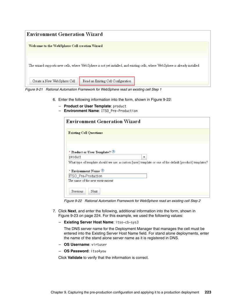
Figure 9-21 Rational Automation Framework for WebSphere read an existing cell Step 1
6. Enter the following information into the form, shown in Figure 9-22:
– Product or User Template: product– Environment Name: ITSO_Pre-Production
Figure 9-22 Rational Automation Framework for WebSphere read an existing cell Step 2
7. Click Next, and enter the following, additional information into the form, shown in Figure 9-23 on page 224. For this example, we used the following values:
– Existing Server Host Name: itso-cb-sys3
The DNS server name for the Deployment Manager that manages the cell must be entered into the Existing Server Host Name field. For stand alone deployments, enter the name of the stand alone server name as it is registered in DNS.
– OS Username: virtuser
– OS Password: itso4you
Click Validate to verify that the information is correct.
Chapter 9. Capturing the pre-production configuration and applying it to a production deployment 223
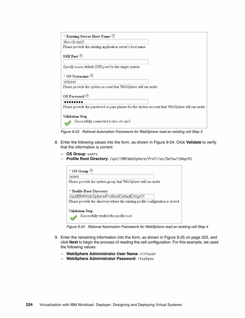
Figure 9-23 Rational Automation Framework for WebSphere read an existing cell Step 3
8. Enter the following values into the form, as shown in Figure 9-24. Click Validate to verify that the information is correct:
– OS Group: users– Profile Root Directory: /opt/IBM/WebSphere/Profiles/DefaultDmgr01
Figure 9-24 Rational Automation Framework for WebSphere read an existing cell Step 4
9. Enter the remaining information into the form, as shown in Figure 9-25 on page 225, and click Next to begin the process of reading the cell configuration. For this example, we used the following values:
– WebSphere Administrator User Name: virtuser– WebSphere Administrator Password: itso4you
224 Virtualization with IBM Workload Deployer: Designing and Deploying Virtual Systems

Figure 9-25 Rational Automation Framework for WebSphere read an existing cell Step 5
10.Click Update Progress Output on the next page to view the current output of the read existing cell configuration process, as shown in Figure 9-26.
Figure 9-26 Rational Automation Framework for WebSphere update progress for read existing cell
The progress output provides information as to which steps are executed, including any associated results. Figure 9-27 on page 226 shows an example of a successful read of a cell configuration.
Chapter 9. Capturing the pre-production configuration and applying it to a production deployment 225

Figure 9-27 Rational Automation Framework for WebSphere read existing cell complete
When this process has completes, both an environment and a project for this cell are created, which you can view by selecting the respective menu items from the main Rational Automation Framework for WebSphere console.
Figure 9-28 shows the resulting environment artifact created during this example.
Figure 9-28 Rational Automation Framework for WebSphere read existing cell environment artifact
Figure 9-29 shows the resulting project artifact created during this example.
Figure 9-29 Rational Automation Framework for WebSphere read existing cell project artifact
9.4.2 Updating the environment configuration for project execution
In this section, we update the environment configuration to support project execution:
1. Log into the server that hosts the Rational Automation Framework for WebSphere as a user that has the privilege necessary to place files into the user actions tree. In this example, the root user is selected. The user actions tree is normally located in the RAFW_HOME/user/actions directory.
226 Virtualization with IBM Workload Deployer: Designing and Deploying Virtual Systems

2. Definition of the WebSphere eXtreme Scale catalog service domain is a prerequisite for caching HTTP sessions. The following steps demonstrate how to create a simple Jython script and to extend the framework to include the new action that defines the required service domain:
a. Create the user actions directory using the mkdir command, as shown in Figure 9-30.
RAFW_HOME/user/actions/configure/was/common/nd/scripts
Figure 9-30 Rational Automation Framework for WebSphere user actions directory creation
b. Create a new Jython script in the user actions directory. The script defines the catalog service domain to the WebSphere Application Server cell. The script file is named createXSDomain.py. Figure 9-31 shows the contents of this new script.
Figure 9-31 Rational Automation Framework for WebSphere action script contents
c. Edit the custom user common action build file, and add the new Ant target to enable execution of the new action:
RAFW_HOME/user/actions/configure/was/common/nd/custom_configure_was_common_nd.xml
Figure 9-32 on page 228 shows the content of the action build file with the updated information in bold.
# createXSDomain.py## This script creates a WebSphere eXtreme Scale service domain within## ToDo: Externalize the eXtreme Scale catalog server:port combination so# that it can be supplied within a field in the RAFW project
AdminTask.createXSDomain('[-name "ITSOCatalogCluster domain" -default true -properties -defineDomainServers [[itso-cb-sys3.itso.ral.ibm.com "" ,6672] [itso-cb-sys11.itso.ral.ibm.com "" ,6772]]]')AdminConfig.save()
Hard coded names and ports: The catalog servers and ports (itso-cb-sys3:6672, itso-cb-sys11:6772) are hard coded into this script for simplicity in our lab environment. For production implementations, a more complex script can be created that requires the host names and port numbers of the catalog servers to be supplied on the command line. Alternatively, variables can be created within Rational Automation Framework for WebSphere whose values can be substituted into this script during execution.
Chapter 9. Capturing the pre-production configuration and applying it to a production deployment 227

Figure 9-32 Rational Automation Framework for WebSphere action build file contents
d. Run the rafw.sh command with the -list option to ensure that the new custom action is successfully created, as shown in Figure 9-33.
Figure 9-33 Rational Automation Framework for WebSphere extreme scale action listing
<?xml version="1.0" encoding="UTF-8"?>
<!--======================================================================Licensed Materials - Property of IBM Corp.IBM Rational Build Forge(c) Copyright IBM Corporation 2005, 2009. All Rights Reserved.
U.S. Government Users Restricted Rights - Use, duplication or disclosure restricted byGSA ADP Schedule Contract with IBM Corp.
File name: custom_configure_was_common_nd.xml
This is the configuration build file.======================================================================-->
<project default="default" basedir="."> <description> Contains custom configuration tasks for WAS 61 ND </description> <target name="itso_create_xs_domain" description="Create the eXtreme Scale service domain" depends="only_execute,scope_init"> <antcall target="call_wsadmin"> <param name="TASK" value="itso_create_xs_domain"/> <param name="SCRIPT_NAME" value="${RAFW_HOME}/user/actions/configure/was/common/nd/scripts/ createXSDomain.py"/> </antcall> </target></project>
228 Virtualization with IBM Workload Deployer: Designing and Deploying Virtual Systems

9.4.3 Creating a project to configure the pre-production environment
In this section, we create a new project to configure future deployments of the pre-production environment:
1. Log into the Rational Automation Framework for WebSphere interface using Rational Automation Framework for WebSphere administrative credentials. Select the Projects menu item (Figure 9-34) from the panel on the left side of the browser.
Figure 9-34 Rational Automation Framework for WebSphere projects menu
2. Fill in the form in the Project Details tab (lower panel) with the required information. For this example, the following values were used:
– Name: ITSO_Configure_Cell - Pre-Production– Environment: RAFW_ITSO_Pre-Production_ITSOpreprodCell_1
Figure 9-35 shows the completed form.
Figure 9-35 Rational Automation Framework for WebSphere project details tab
3. Click Save to create the new project.
Chapter 9. Capturing the pre-production configuration and applying it to a production deployment 229

Figure 9-36 New project
4. The new project contains a series of steps. The first step locks the environment definition. This action prevents environment modification while the project is running:
a. Click Add Step at the top of the project window.
b. Fill in the form with the following values:
– Name: call RAFW_Lock_Env_Cell_Library– Path: Absolute
A path can be relative or absolute. If you specify Relative, step commands are executed in a path found by adding together the server, project, job, and step directories. If you specify Absolute, step commands are executed in a path found by adding together the server and step directories. This option allows you to access directories that are not in the project directory structure.
– Inline: RAFW_Lock_Env_Cell_Library
This field specifies an existing project or library to run.
– Command: echo "calling RAFW_Lock_Env_Cell_Library"
A command to run. This can be an operating system command, dot command, or a combination of both. You will see examples of more complex commands in later steps. This field must be populated. Because we selected a library to run inline, we simply put an echo command.
– Timeout in Minutes: 5
Specifies how many minutes the system waits for the current command to produce output. A value of 0 means that the step does not timeout if the step properly connects to the agent. If the timeout value is reached, the system fails the step. The project also fails unless the step is set to Continue on Fail.
– Selector: - Default -
Specifies a selector to use to choose a server for this step. If left as Default, the step executes on the server determined by the project's selector.
– Result: - Exit Code -
Determines how the system judges whether a step succeeded or failed. If you specify Exit Code, the success is determined based on an exit code returned by the command shell.
230 Virtualization with IBM Workload Deployer: Designing and Deploying Virtual Systems

Click Save Step.
Figure 9-37 shows an example of the completed form.
Figure 9-37 Rational Automation Framework for WebSphere Project Step 1
5. After saving, the form is cleared so you can add the next step. This step sets a project variable for the location of the environment definition file. Click Save Step again after the following values are added:
– Name: Set Properties File
– Path: Absolute
– Command: In this case, we enter a command to execute. The .bset command changes project settings temporarily during a job:
.bset env "BATCH_FILE_PATH=/opt/ibm/rational/buildforge/rafw/work/${ENVIRONMENT}-${CELL_NAME}.properties"
– Timeout in Minutes: 5
– Selector: - Default -
– Result: - Exit Code -
Figure 9-38 on page 232 shows an example of the completed form.
Chapter 9. Capturing the pre-production configuration and applying it to a production deployment 231

Figure 9-38 Rational Automation Framework for WebSphere Project Step 2
6. The next project step updates the environment definition file to enable execution of WebSphere Virtual Enterprise actions within Rational Automation Framework for WebSphere. Fill in the form with the following values, and click Save Step:
– Name: Update Properties File
– Path: Absolute
– Command:
/bin/sed -i 's/^CELL_TYPE=WAS/CELL_TYPE=WVE/' ${BATCH_FILE_PATH}
/bin/sed -i 's/^NUMBER_OF_CLUSTERS=0/NUMBER_OF_CLUSTERS=2/' ${BATCH_FILE_PATH}
/bin/sed -i 's/^PRODUCT_VERSION=WAS70/PRODUCT_VERSION=WVE61/' ${BATCH_FILE_PATH}
/bin/sed -i 's/^CLUSTERS=/CLUSTERS=ITSOCacheCluster/' ${BATCH_FILE_PATH}
– Timeout in Minutes: 5
– Selector: - Default -
– Result: - Exit Code -
Figure 9-39 on page 233 shows the completed form for this step.
232 Virtualization with IBM Workload Deployer: Designing and Deploying Virtual Systems

Figure 9-39 Rational Automation Framework for WebSphere Project Step 3
7. Now the environment definition file is augmented to include elements, such as product version and cluster definitions. These elements are required to populate the user environment tree during the next step. Enter the following values and click Save Step:
– Name: Augment Properties File
– Path: Absolute
– Command:
cat >> ${BATCH_FILE_PATH} << EOF
WVE_VERSION=61
DYNCLUSTERS=ITSOdynCluster
CLUSTER1_CLUSTER_NAME=ITSOCacheCluster
CLUSTER1_CLUSTER_NODES=`/bin/awk -F= '/^NODES=/ {print $2}' ${BATCH_FILE_PATH} | /bin/awk -F, '{ORS = ","} {for(i=1;i<=NF;i++) {if($i ~ /CacheNode/) {print $i}}}' | /bin/sed 's/,$/\n/'`
CLUSTER1_CLUSTER_TYPE=WAS
CLUSTER1_PERNODE=1
CLUSTER1_PREFIX=ITSOCache
CLUSTER1_TRANSPORT_STARTING_POINT=0
CLUSTER1_TRANSPORT_NODE_INCREMENTOR=0
CLUSTER2_CLUSTER_NAME=ITSOdynCluster
CLUSTER2_CLUSTER_TYPE=DYNAMIC_WAS
CLUSTER2_MEMBERSHIP_POLICY=node_name LIKE \'dynClustNode*\'
EOF
– Timeout in Minutes: 5
Chapter 9. Capturing the pre-production configuration and applying it to a production deployment 233

– Selector: - Default -
– Result: - Exit Code -
Figure 9-40 shows an example of the completed form.
Figure 9-40 Rational Automation Framework for WebSphere Project Step 4
8. Updating the user environment tree is performed by executing the Rational Automation Framework for WebSphere environment generation against the augmented definition file. Enter the following values, and click Save Step:
– Name: Update RAFW Environment
– Path: Absolute
– Command: ${RAFW_HOME}/bin/rafwEnvBuild${SCRIPT_EXT} -b "${BATCH_FILE_PATH}" -genRAFWEnv
– Timeout in Minutes: 5
– Selector: - Default -
– Result: - Exit Code -
Figure 9-41 on page 235 shows the completed form for this step.
234 Virtualization with IBM Workload Deployer: Designing and Deploying Virtual Systems

Figure 9-41 Rational Automation Framework for WebSphere Project Step 5
9. The WebSphere eXtreme Scale service domain provides a location for the HTTP sessions to be stored. The service domain is created in this project step. Enter the following values, and click Save Step:
– Name: Create eXtreme Scale Service Domain
– Path: Absolute
– Command: ${RAFW_HOME}/bin/rafw${SCRIPT_EXT} -env ${ENVIRONMENT} -cell ${CELL_NAME} ${MODE} itso_create_xs_domain
– Timeout in Minutes: 10
– Selector: - Default -
– Result: RAFW
We specify RAFW whenever there is an action or inline library in the project step so that any return or exit codes are handled by Rational Automation Framework for WebSphere.
Figure 9-42 on page 236 shows the completed form for this step.
Chapter 9. Capturing the pre-production configuration and applying it to a production deployment 235

Figure 9-42 Rational Automation Framework for WebSphere Project Step 6
10.Create the application server cluster (ITSOCacheCluster) that will host the WebSphere eXtreme Scale grid. Enter the following values, and click Save Step:
– Name: Create WXS Cluster
– Path: Absolute
– Command: ${RAFW_HOME}/bin/rafw${SCRIPT_EXT} -env ${ENVIRONMENT} -cell ${CELL_NAME} -cluster ITSOCacheCluster ${MODE} was_common_configure_create_cluster
– Timeout in Minutes: 5
– Selector: - Default -
– Result: RAFW
An example of the completed form can be seen in Figure 9-43 on page 237.
236 Virtualization with IBM Workload Deployer: Designing and Deploying Virtual Systems
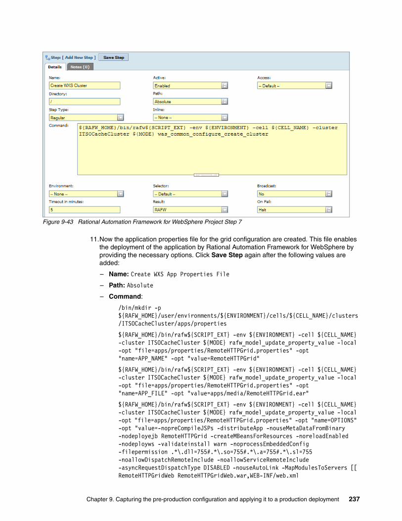
Figure 9-43 Rational Automation Framework for WebSphere Project Step 7
11.Now the application properties file for the grid configuration are created. This file enables the deployment of the application by Rational Automation Framework for WebSphere by providing the necessary options. Click Save Step again after the following values are added:
– Name: Create WXS App Properties File
– Path: Absolute
– Command:
/bin/mkdir -p ${RAFW_HOME}/user/environments/${ENVIRONMENT}/cells/${CELL_NAME}/clusters/ITSOCacheCluster/apps/properties
${RAFW_HOME}/bin/rafw${SCRIPT_EXT} -env ${ENVIRONMENT} -cell ${CELL_NAME} -cluster ITSOCacheCluster ${MODE} rafw_model_update_property_value -local -opt "file=apps/properties/RemoteHTTPGrid.properties" -opt "name=APP_NAME" -opt "value=RemoteHTTPGrid"
${RAFW_HOME}/bin/rafw${SCRIPT_EXT} -env ${ENVIRONMENT} -cell ${CELL_NAME} -cluster ITSOCacheCluster ${MODE} rafw_model_update_property_value -local -opt "file=apps/properties/RemoteHTTPGrid.properties" -opt "name=APP_FILE" -opt "value=apps/media/RemoteHTTPGrid.ear"
${RAFW_HOME}/bin/rafw${SCRIPT_EXT} -env ${ENVIRONMENT} -cell ${CELL_NAME} -cluster ITSOCacheCluster ${MODE} rafw_model_update_property_value -local -opt "file=apps/properties/RemoteHTTPGrid.properties" -opt "name=OPTIONS" -opt "value=-nopreCompileJSPs -distributeApp -nouseMetaDataFromBinary -nodeployejb RemoteHTTPGrid -createMBeansForResources -noreloadEnabled -nodeployws -validateinstall warn -noprocessEmbeddedConfig -filepermission .*\.dll=755#.*\.so=755#.*\.a=755#.*\.sl=755 -noallowDispatchRemoteInclude -noallowServiceRemoteInclude -asyncRequestDispatchType DISABLED -nouseAutoLink -MapModulesToServers [[ RemoteHTTPGridWeb RemoteHTTPGridWeb.war,WEB-INF/web.xml
Chapter 9. Capturing the pre-production configuration and applying it to a production deployment 237

WebSphere:cell=${CELL_NAME},cluster=ITSOCacheCluster ]] -MapWebModToVH [[ RemoteHTTPGridWeb RemoteHTTPGridWeb.war,WEB-INF/web.xml default_host ]]"
– Timeout in Minutes: 5
– Selector: - Default -
– Result: RAFW
Figure 9-44 shows an example of the completed form.
Figure 9-44 Rational Automation Framework for WebSphere Project Step 8
12.In this step the application EAR file is copied into the ITSOCacheCluster media directory to fulfill the application deployment dependencies. Populate the form, and click Save Step. For this step, in the example, the following values were used:
– Name: Copy WXS App To Media Directory
– Path: Absolute
– Command:
/bin/mkdir -p ${RAFW_HOME}/user/environments/${ENVIRONMENT}/cells/${CELL_NAME}/clusters/ITSOCacheCluster/apps/media
/bin/cp /tmp/RemoteHTTPGrid.ear ${RAFW_HOME}/user/environments/${ENVIRONMENT}/cells/${CELL_NAME}/clusters/ITSOCacheCluster/apps/media
Command assist option: The application deployment options can be obtained by performing a test deployment of the application using the WebSphere administrative console with the command assist option enabled.
Note: Delete any -appname -mapToServers references from the deployment options. Rational Automation Framework for WebSphere automatically populates these.
238 Virtualization with IBM Workload Deployer: Designing and Deploying Virtual Systems

– Timeout in Minutes: 5
– Selector: - Default -
– Result: - Exit Code -
Figure 9-45 shows the completed form for this step.
Figure 9-45 Rational Automation Framework for WebSphere Project Step 9
13.The final step to configure the ITSOCacheCluster is to deploy the grid configuration and make it available for use. Enter the following values, and click Save Step:
– Name: Deploy WXS Grid Configuration
– Path: Absolute
– Command: ${RAFW_HOME}/bin/rafw${SCRIPT_EXT} -env ${ENVIRONMENT} -cell ${CELL_NAME} -cluster ITSOCacheCluster ${MODE} was_common_deploy_install_app -a RemoteHTTPGrid
– Timeout in Minutes: 10
– Selector: - Default -
– Result: RAFW
Figure 9-46 on page 240 shows an example of the completed form.
Chapter 9. Capturing the pre-production configuration and applying it to a production deployment 239

Figure 9-46 Rational Automation Framework for WebSphere Project Step 10
14.The ITSOCacheCluster must be started prior to deploying and starting the HTTP session test application. This project step starts the cluster. Enter the following values, and click Save Step:
– Name: Start Cache Cluster
– Path: Absolute
– Command: ${RAFW_HOME}/bin/rafw${SCRIPT_EXT} -env ${ENVIRONMENT} -cell ${CELL_NAME} -cluster ITSOCacheCluster ${MODE} was_common_configure_start_cluster
– Timeout in Minutes: 10
– Selector: - Default -
– Result: RAFW
Figure 9-47 on page 241 shows the completed form for this step.
240 Virtualization with IBM Workload Deployer: Designing and Deploying Virtual Systems

Figure 9-47 Rational Automation Framework for WebSphere Project Step 11
15.Creating the dynamic cluster that will house the HTTP session persistent test application is next. Enter the following values, and click Save Step:
– Name: Create Dynamic Cluster
– Path: Absolute
– Command: ${RAFW_HOME}/bin/rafw${SCRIPT_EXT} -env ${ENVIRONMENT} -cell ${CELL_NAME} -cluster ITSOdynCluster ${MODE} wve_common_configure_create_dyncluster
– Timeout in Minutes: 5
– Selector: - Default -
– Result: RAFW
Figure 9-48 on page 242 shows the completed form for this step.
Tip: The dynamic cluster that is created as part of this example has its Operational Mode set to manual by default. It is possible to introduce another step within the project that sets the mode to automatic and can be an ideal configuration for some production application environments.
Chapter 9. Capturing the pre-production configuration and applying it to a production deployment 241

Figure 9-48 Rational Automation Framework for WebSphere Project Step 12
16.Now the properties file for the HTTP session test application is created. This file enables the deployment of the application by Rational Automation Framework for WebSphere by providing the necessary options. Enter the following values, and click Save Step:
– Name: Create HTTP Session App Properties File
– Path: Absolute
– Command:
/bin/mkdir -p ${RAFW_HOME}/user/environments/${ENVIRONMENT}/cells/${CELL_NAME}/clusters/ITSOdynCluster/apps/properties
${RAFW_HOME}/bin/rafw${SCRIPT_EXT} -env ${ENVIRONMENT} -cell ${CELL_NAME} -cluster ITSOdynCluster ${MODE} rafw_model_update_property_value -local -opt "file=apps/properties/HttpSessPersistence.properties" -opt "name=APP_NAME" -opt "value=HttpSessPersistence"
${RAFW_HOME}/bin/rafw${SCRIPT_EXT} -env ${ENVIRONMENT} -cell ${CELL_NAME} -cluster ITSOdynCluster ${MODE} rafw_model_update_property_value -local -opt "file=apps/properties/HttpSessPersistence.properties" -opt "name=APP_FILE" -opt "value=apps/media/HttpSessPersistence.ear"
${RAFW_HOME}/bin/rafw${SCRIPT_EXT} -env ${ENVIRONMENT} -cell ${CELL_NAME} -cluster ITSOdynCluster ${MODE} rafw_model_update_property_value -local -opt "file=apps/properties/HttpSessPersistence.properties" -opt "name=OPTIONS" -opt "value=-nopreCompileJSPs -distributeApp -nouseMetaDataFromBinary -nodeployejb -appname HttpSessPersistence -createMBeansForResources -noreloadEnabled -nodeployws -validateinstall warn -noprocessEmbeddedConfig -filepermission .*\.dll=755#.*\.so=755#.*\.a=755#.*\.sl=755 -noallowDispatchRemoteInclude -noallowServiceRemoteInclude -asyncRequestDispatchType DISABLED -nouseAutoLink -SessionManagement [[true XSRemoteSessionManagement ITSOCatalogCluster:!:session]]-MapModulesToServers [[ HttpSessPersistence
242 Virtualization with IBM Workload Deployer: Designing and Deploying Virtual Systems

HttpSess.war,WEB-INF/web.xml WebSphere:cell=${CELL_NAME},cluster=ITSOdynCluster ]]"
– Timeout in Minutes: 5
– Selector: - Default -
– Result: RAFW
Figure 9-49 shows an example of the completed form.
Figure 9-49 Rational Automation Framework for WebSphere Project Step 13
17.In this step, the application EAR file is copied into the dynamic cluster media directory to fulfill the application deployment dependencies. Enter the following values, and click Save Step:
– Name: Copy HTTP Session App To Media Directory
– Path: Absolute
– Command:
/bin/mkdir -p ${RAFW_HOME}/user/environments/${ENVIRONMENT}/cells/${CELL_NAME}/clusters/ITSOdynCluster/apps/media
Notes:
� The application deployment options can be obtained by performing a test deployment of the application using the WebSphere administrative console with the command assist option enabled.
� Delete any -appname -mapToServers references from the deployment options. Rational Automation Framework for WebSphere automatically populates these.
� The -SessionManagement [[true XSRemoteSessionManagement ITSOCatalogCluster:!:session]] enables the application to use the WebSphere eXtreme Scale remote grid to manage the HTTP sessions.
Chapter 9. Capturing the pre-production configuration and applying it to a production deployment 243

/bin/cp /tmp/HttpSessPersistence.ear ${RAFW_HOME}/user/environments/${ENVIRONMENT}/cells/${CELL_NAME}/clusters/ITSOdynCluster/apps/media
– Timeout in Minutes: 5
– Selector: - Default -
– Result: - Exit Code -
Figure 9-50 shows the completed form for this step.
Figure 9-50 Rational Automation Framework for WebSphere Project Step 14
18.Now the HTTP session test application is deployed. Enter the following values, and click Save Step:
– Name: Deploy HTTP Session App
– Path: Absolute
– Command: ${RAFW_HOME}/bin/rafw${SCRIPT_EXT} -env ${ENVIRONMENT} -cell ${CELL_NAME} -cluster ITSOdynCluster ${MODE} was_common_deploy_install_app -a HttpSessPersistence
– Timeout in Minutes: 10
– Selector: - Default -
– Result: RAFW
Figure 9-51 on page 245 shows the completed form for this project step.
244 Virtualization with IBM Workload Deployer: Designing and Deploying Virtual Systems

Figure 9-51 Rational Automation Framework for WebSphere Project Step 15
19.Because a dynamic cluster is being used for the HTTP session test application, the cluster must be restarted to recognize the newly deployed application. This project step stops the dynamic cluster. Enter the following values, and click Save Step:
– Name: Stop Dynamic Cluster
– Path: Absolute
– Command: ${RAFW_HOME}/bin/rafw${SCRIPT_EXT} -env ${ENVIRONMENT} -cell ${CELL_NAME} -cluster ITSOdynCluster ${MODE} wve_common_configure_stop_dyncluster
– Timeout in Minutes: 10
– Selector: - Default -
– Result: RAFW
Figure 9-52 on page 246 shows the completed form for this step.
Chapter 9. Capturing the pre-production configuration and applying it to a production deployment 245

Figure 9-52 Rational Automation Framework for WebSphere Project Step 16
20.The next step starts the dynamic cluster. Enter the following values, and click Save Step:
– Name: Start Dynamic Cluster
– Path: Absolute
– Command: ${RAFW_HOME}/bin/rafw${SCRIPT_EXT} -env ${ENVIRONMENT} -cell ${CELL_NAME} -cluster ITSOdynCluster ${MODE} wve_common_configure_start_dyncluster
– Timeout in Minutes: 10
– Selector: - Default -
– Result: RAFW
Figure 9-53 on page 247 shows the completed form for this project step.
246 Virtualization with IBM Workload Deployer: Designing and Deploying Virtual Systems

Figure 9-53 Rational Automation Framework for WebSphere Project Step 17
21.The final step in the project unlocks the environment definition and allows modifications to the environment. Enter the following values, and click Save Step:
– Name: call RAFW_Release_Lock_Env_Cell_Library
– Path: Absolute
– Inline: RAFW_Release_Lock_Env_Cell_Library
– Command: echo "calling RAFW_Release_Lock_Env_Cell_Library"
– Timeout in Minutes: 5
– Selector: - Default -
– Result: - Exit Code -
Figure 9-54 on page 248 shows an example of the completed form.
Chapter 9. Capturing the pre-production configuration and applying it to a production deployment 247

Figure 9-54 Rational Automation Framework for WebSphere Project Step 18
22.The remaining step in this section modifies the project Tags so that a meaningful identifier is used during project runs. The default tag format for any new project is BUILD_$B where the $B variable indicates the project run number and increments automatically. Modifying this format allows easier tracking of the project status within the job listing.
Select the Projects menu, and click Project Edit to the left of the project, shown in Figure 9-55, that was just created (ITSO_Configure_Cell - Pre-Production).
Figure 9-55 Rational Automation Framework for WebSphere edit project button
23.Click the Tags tab in the bottom panel, modify the tag as indicated, and click Save. For this example the following value was entered:
– Tag Format: ITSO_Configure_Cell - Pre-Production_$B
Figure 9-56 shows the updated Tags form.
Figure 9-56 Rational Automation Framework for WebSphere updated tag format
248 Virtualization with IBM Workload Deployer: Designing and Deploying Virtual Systems

9.5 Testing the project to configure the pre-production environment
The ITSO_Configure_Cell - Pre-Production project will now be used to perform the following actions against a new virtual system provisioned using IBM Workload Deployer:
1. Create both standard and dynamic WebSphere clusters.2. Create a WebSphere eXtreme Scale catalog service domain.3. Configure a cache cluster.4. Deploy the sample HTTP test application.5. Start all services.
To start the project:
1. Log into the Rational Automation Framework for WebSphere server using administrator credentials. In this example, we use the root user.
2. Select the Projects menu from the panel on the left side, and click ITSO_Configure_Cell - Pre-Production, as shown in Figure 9-57.
Figure 9-57 Rational Automation Framework for WebSphere projects menu
This action opens the project management panel, as shown in Figure 9-58.
Figure 9-58 Rational Automation Framework for WebSphere project management window
Chapter 9. Capturing the pre-production configuration and applying it to a production deployment 249

3. Click Start Project at the top of this panel to begin the job execution process. A new panel is displayed that allows you to customize the project invocation parameters. Two tabs are available: Job Details (Figure 9-59) and Job Steps (Figure 9-60).
Figure 9-59 Rational Automation Framework for WebSphere job details
The Job Steps tab, Figure 9-60, is useful if there is a requirement to invoke only certain portions of a complex job (for example to start server) or if a restart of a failed job is necessary.
Figure 9-60 Rational Automation Framework for WebSphere job steps
For this example, only the Job Details tab is used:
4. Verify that the following field and value combination is correct:
– MODE: Execute
5. Click Execute at the top of the Job Details tab to start this project, shown in Figure 9-59. After the job starts, a new page is displayed that provides information regarding the current project status, including details for each step.
6. Select any job step link to view the messages associated with the execution of the project step. For this example the Deploy WXS Grid Configuration link is selected, as shown in Figure 9-61 on page 251.
250 Virtualization with IBM Workload Deployer: Designing and Deploying Virtual Systems

Figure 9-61 Rational Automation Framework for WebSphere project job step detailed messages
The final status of the project execution can be viewed in two ways. One is to use the Jobs menu. Figure 9-62 shows a successful completion status using this process.
Figure 9-62 Rational Automation Framework for WebSphere project status using the jobs menu
The second option is to review the project status from the Home Completed Runs menu that is shown in Figure 9-63 on page 252. The main difference between the two options is that one shows the result of each job step while the other indicates only the status of the project as a whole.
Chapter 9. Capturing the pre-production configuration and applying it to a production deployment 251

Figure 9-63 Rational Automation Framework for WebSphere project status using the completed runs menu
After the project completes successfully, validate the proper operation of all components. In this case, repeat the validation steps in 8.9, “Testing the configuration” on page 206. It is important to test any new project to ensure that all steps are performing as expected and that the desired result is achieved. After you finish project testing, perform this validation for every project run. Rational Automation Framework for WebSphere provides failure status and corresponding codes if an unexpected project result occurs.
9.6 Deploying and configuring the production environment
To deploy and configure the production environment, we must promote the pre-production project in Rational Automation Framework for WebSphere to a production version, clone the existing pattern in IBM Workload Deployer, and add the Rational Automation Framework for WebSphere script package. This script package is provided with the Rational Automation Framework for WebSphere installation and must be added to the IBM Workload Deployer script package catalog. The process for adding this script to the catalog is provided in 9.3.3, “Adding the script package to the IBM Workload Deployer” on page 218.
9.6.1 Promoting the pre-production project to production
In 9.4, “Using Rational Automation Framework for WebSphere to configure the ITSO pre-production cell” on page 221, Rational Automation Framework for WebSphere was configured to support the unique characteristics of the pre-production environment. The changes made included:
� Creation of Jython scripts to enable configuration of WebSphere eXtreme Scale service domains
� Augmenting the cell environment definition to include additional clusters and applications
� Updating the environment within Rational Automation Framework for WebSphere
� Creation of dynamic and standard clusters within the cell
� Deployment of the WebSphere eXtreme Scale grid configuration
� Installation and enablement of the HTTP session test application
Performing these activities again to configure the production environment requires investing valuable time. By using Rational Automation Framework for WebSphere, you can significantly reduce the time involved. In this section of the chapter, the promotion of the pre-production cell configuration project to a production project is demonstrated.
After you perform these actions, you can deploy the production cell using IBM Workload Deployer and configure it automatically using the integration script provided with Rational Automation Framework for WebSphere.
252 Virtualization with IBM Workload Deployer: Designing and Deploying Virtual Systems

9.6.2 Cloning the pre-production configuration project
In this section, the pre-production project is cloned and renamed to support automatic configuration of the production cell:
1. Log into the Rational Automation Framework for WebSphere interface using Rational Automation Framework for WebSphere administrative credentials.
2. Select the Projects menu, and click Project Edit to the left of the ITSO_Configure_Cell - Pre-Production project, as shown in Figure 9-64.
Figure 9-64 Rational Automation Framework for WebSphere edit project button
3. Click Copy Project, as shown in Figure 9-65 to clone the pre-production project. The cloned project appears in the projects list with the name ITSO_Configure_Cell - Pre-Production Copy.
Figure 9-65 Rational Automation Framework for WebSphere copy project button
4. Select the Projects menu again, and click Project Edit to the left of the ITSO_Configure_Cell - Pre-Production Copy project to open the project for updating.
5. We update the project name and tags to reflect the production status of this project. Change the settings for the project, and click Save.
Figure 9-66 shows the updated Project Details tab. Change the settings for the project to the following values:
– Name (Project Details Tab): ITSO_Configure_Cell - Production– Environment (Project Details Tab): - None -
Figure 9-66 Rational Automation Framework for WebSphere updated project details tab
6. Click Save.
7. Select the Tags tab, and update the Tag Format to:
ITSO_Configure_Cell - Production_$B
Chapter 9. Capturing the pre-production configuration and applying it to a production deployment 253
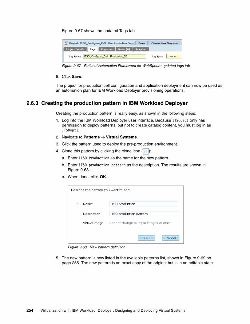
Figure 9-67 shows the updated Tags tab.
Figure 9-67 Rational Automation Framework for WebSphere updated tags tab
8. Click Save.
The project for production cell configuration and application deployment can now be used as an automation plan for IBM Workload Deployer provisioning operations.
9.6.3 Creating the production pattern in IBM Workload Deployer
Creating the production pattern is really easy, as shown in the following steps:
1. Log into the IBM Workload Deployer user interface. Because ITSOdep1 only has permission to deploy patterns, but not to create catalog content, you must log in as ITSOopt1.
2. Navigate to Patterns Virtual Systems.
3. Click the pattern used to deploy the pre-production environment.
4. Clone this pattern by clicking the clone icon ( ):
a. Enter ITSO Production as the name for the new pattern.
b. Enter ITSO production pattern as the description. The results are shown in Figure 9-68.
c. When done, click OK.
Figure 9-68 New pattern definition
5. The new pattern is now listed in the available patterns list, shown in Figure 9-69 on page 255. The new pattern is an exact copy of the original but is in an editable state.
254 Virtualization with IBM Workload Deployer: Designing and Deploying Virtual Systems

Figure 9-69 The new pattern in an editable state
6. First, grant the ITSOdeps group read access to the pattern so the ITSOdep1 user can deploy the virtual system. To grant the permission to the group, click the Access granted to dialog box, and select the ITSOdeps group. As a result, the group is now listed in the access list, as shown in Figure 9-70.
Figure 9-70 Grant access to the ITSOdeps group
7. Edit this pattern to make the appropriate changes to the system by clicking Edit ( ). The console looks similar to Figure 9-71.
Figure 9-71 Edit pattern panel
Chapter 9. Capturing the pre-production configuration and applying it to a production deployment 255

8. Before we deploy the system, we must add the Rational Automation Framework for WebSphere script package. Click the Scripts heading on the left side of the pattern editor to display the script packages available.
Drag-and-drop the Rational Automation Framework for WebSphere script package to the Deployment Manager part. The Deployment Manager part now looks similar to Figure 9-72.
Figure 9-72 Deployment manager virtual part after adding the Rational Automation Framework script package
The Rational Automation Framework for WebSphere script package requires you to provide additional information. We can add the information at deployment time or define it now. In our sample, we provide the information at deployment time.
The ITSO production pattern is now complete.
9.6.4 Creating the production environment profile
Before we can deploy the production pattern, we must create an environment profile to deploy it. You can perform this process as described in 7.2, “Creating an environment profile” on page 149 for the pre-production environment profile, or you can simply clone the pre-production environment profile and change a few required details.
To clone the pattern:
1. Select Cloud Environment Profiles, as shown in Figure 9-73.
Figure 9-73 Environment profile menu
2. Select the ITSO pre-prod profile, and click Clone ( ) to start the process.
3. Fill in the information for the new profile, as shown in Figure 9-74 on page 257:
– Name: ITSO production profile
– Description: This is the ITSO production profile
Click OK.
256 Virtualization with IBM Workload Deployer: Designing and Deploying Virtual Systems
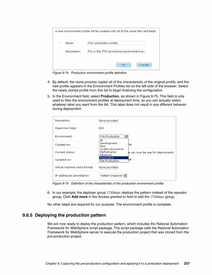
Figure 9-74 Production environment profile definition
4. By default, the clone process copies all of the characteristic of the original profile, and the new profile appears in the Environment Profiles list on the left side of the browser. Select the newly cloned profile from this list to begin finalizing the configuration.
5. In the Environment field, select Production, as shown in Figure 9-75. This field is only used to filter the environment profiles at deployment time, so you can actually select whatever label you want from the list. This label does not result in any different behavior during deployment.
Figure 9-75 Definition of the characteristic of the production environment profile
6. In our example, the deployer group ITSOdeps deploys the pattern instead of the operator group. Click Add more in the Access granted to field to add the ITSOdeps group.
No other steps are required for our purpose. The environment profile is complete.
9.6.5 Deploying the production pattern
We are now ready to deploy the production pattern, which includes the Rational Automation Framework for WebSphere script package. The script package calls the Rational Automation Framework for WebSphere server to execute the production project that was cloned from the pre-production project.
Chapter 9. Capturing the pre-production configuration and applying it to a production deployment 257

To deploy the pattern:
1. Log into the IBM Workload Deployer console as ITSOdep1 and navigate to Pattern Virtual Systems.
2. Select the ITSO production pattern, as shown in Figure 9-76.
Figure 9-76 ITSO production pattern selection
3. Click Deploy ( ) to start the deployment and provide the virtual system name.
4. Expand Choose Environment:
a. Select Choose profile.b. Select Production as the Type.c. Select ITSO production profile as the Profile.
This is shown in Figure 9-77. By choosing Production as the type, we filter the environment profiles, which is why the ITSO pre-production profile does not appear in the list.
Figure 9-77 Environment profile selection
5. Configure the virtual parts, shown in Figure 9-78. Select each part, and complete the required information.
Figure 9-78 Virtual parts composing the pattern
Read permission: If you do not see the pattern, be sure you granted the read permission to the ITSOdeps group.
258 Virtualization with IBM Workload Deployer: Designing and Deploying Virtual Systems

6. Now we must provide the IP addresses and host names of the images that we are deploying. For each virtual part:
a. Click the virtual part in the list to open the configuration page.b. Select the cloud group.c. Select the IP group.d. Enter the IP address for the part.
An example is shown in Figure 9-79 for the IBM HTTP Server.
Figure 9-79 Providing the host name and IP address
7. Open the Deployment Manager part again, and provide the information needed by the Rational Automation Framework for WebSphere script package, shown in Figure 9-80 on page 260. Providing this information enables IBM Workload Deployer to call the production configuration project upon completion of system deployment.
Tip: When you create a multi-image pattern there is no way to identify the similar parts by name. In our case, it was difficult to determine which part was the server and which was the client. The parts are listed in the order that you drag them to the dashboard, but this might not be enough.
To solve this issue, we created two simple script packages that only contained a cbscript.json file. The names of the script packages included “client” and “server”. Adding the script package to the appropriate parts gave us a label of sorts for the part (because the name of the script package is displayed in the part).
Chapter 9. Capturing the pre-production configuration and applying it to a production deployment 259

Figure 9-80 Rational Automation Framework for WebSphere script configuration
8. After all of the parts are configured, the dialog window will have all green check marks, as shown in Figure 9-81, and the pattern is ready to be deployed.
Figure 9-81 Ready for the deployment
9. Deploy the pattern and then test the configuration, as described in 8.9, “Testing the configuration” on page 206.
260 Virtualization with IBM Workload Deployer: Designing and Deploying Virtual Systems

Part 3 Post deployment
This part provides information about post-deployment issues. Life cycle management is about repeating the deployment of the infrastructure for an application as it moves through its life cycle stages. Consistency in the configuration of the application server environment is key to maintaining the stability of the application. The goal is to ensure that the way that an application performs during test is also the way it performs during production.
This part also discusses the troubleshooting features in the IBM Workload Deployer that will help you ensure that your private cloud deployment continues to function properly.
This part contains the following chapters:
� Chapter 10, “Life cycle management” on page 263� Chapter 11, “Monitoring and troubleshooting environment” on page 319
Part 3
© Copyright IBM Corp. 2011. All rights reserved. 261

262 Virtualization with IBM Workload Deployer: Designing and Deploying Virtual Systems

Chapter 10. Life cycle management
This chapter explores the customization capability within IBM Workload Deployer to manage the life cycle of virtual systems, image and deployment patterns, the application environment, and licensing.
This chapter contains the following topics:
� 10.1, “Overview” on page 264
� 10.2, “Virtual system maintenance” on page 264
� 10.3, “Applying maintenance with IBM Workload Deployer” on page 265
� 10.4, “Applying maintenance with Rational Automation Framework for WebSphere” on page 269
� 10.5, “Managing images and patterns: Strategic approach” on page 293
� 10.6, “Managing application updates” on page 305
� 10.7, “Managing the appliance” on page 308
� 10.8, “Managing licenses” on page 313
10
© Copyright IBM Corp. 2011. All rights reserved. 263

10.1 Overview
IBM Workload Deployer comes with a number of virtual images and deployment patterns preinstalled. These images and patterns can be customized to adapt to diverse cloud environments. Customization can occur at the operating system, the middleware layer, and all the way to the application tier.
Figure 10-1 shows the layers of customization within the cloud as a way to isolate those objects that are predominantly static from the dynamic ones. These layers of customization typically relate to distinct teams (infrastructure, operations, and application) in charge of maintaining the various pieces of the infrastructure, namely, the operating system environments, middleware environments, and applications.
Figure 10-1 Workload Deployer image and pattern customization overview
The sections that follow address the customization that can happen at layers of the deployment infrastructure.
10.2 Virtual system maintenance
Maintaining application environments can be a repetitive and time consuming process. Maintenance actions include delivering fixes and upgrades to the application environment and to the infrastructure on which they depend. IBM Workload Deployer does not eliminate the need for such maintenance, but it does make the delivery of maintenance to your applications and application infrastructure simple, consistent, and fast.
Infrastructure team Clones patternand customizes
topology
Infrastructure team
Applications team
Extendsimage
Provides deploytime parameters
Custom image
Sourcedfrom
Customizeswith
applications
Sourcedfrom
IBMWebSphere application server
hypervisor edition
Clusterpattern
Customnode
Customnode
DMgr/IHS
Custom clusterpattern
DMgr/IHS
Finance Application Pattern
DMgr/IHS Custom software
Customnode
Custom software
Customnode
Custom software
Finance application virtual system
FinanceDMgr
Custom software
FinanceNode0
Custom software
FinanceNode1
Custom software Custom software
Operations team
Custom software
Customnode
Custom software
Customnode
264 Virtualization with IBM Workload Deployer: Designing and Deploying Virtual Systems
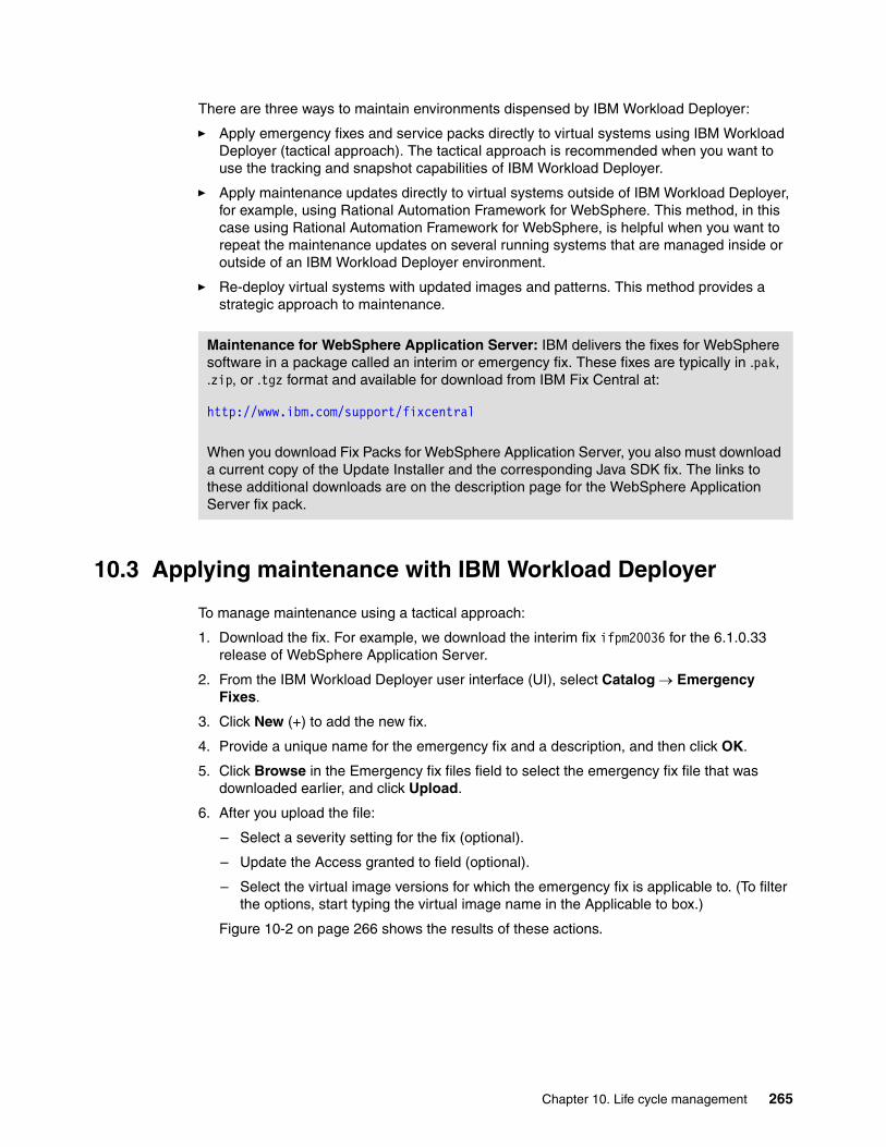
There are three ways to maintain environments dispensed by IBM Workload Deployer:
� Apply emergency fixes and service packs directly to virtual systems using IBM Workload Deployer (tactical approach). The tactical approach is recommended when you want to use the tracking and snapshot capabilities of IBM Workload Deployer.
� Apply maintenance updates directly to virtual systems outside of IBM Workload Deployer, for example, using Rational Automation Framework for WebSphere. This method, in this case using Rational Automation Framework for WebSphere, is helpful when you want to repeat the maintenance updates on several running systems that are managed inside or outside of an IBM Workload Deployer environment.
� Re-deploy virtual systems with updated images and patterns. This method provides a strategic approach to maintenance.
10.3 Applying maintenance with IBM Workload Deployer
To manage maintenance using a tactical approach:
1. Download the fix. For example, we download the interim fix ifpm20036 for the 6.1.0.33 release of WebSphere Application Server.
2. From the IBM Workload Deployer user interface (UI), select Catalog Emergency Fixes.
3. Click New (+) to add the new fix.
4. Provide a unique name for the emergency fix and a description, and then click OK.
5. Click Browse in the Emergency fix files field to select the emergency fix file that was downloaded earlier, and click Upload.
6. After you upload the file:
– Select a severity setting for the fix (optional).
– Update the Access granted to field (optional).
– Select the virtual image versions for which the emergency fix is applicable to. (To filter the options, start typing the virtual image name in the Applicable to box.)
Figure 10-2 on page 266 shows the results of these actions.
Maintenance for WebSphere Application Server: IBM delivers the fixes for WebSphere software in a package called an interim or emergency fix. These fixes are typically in .pak, .zip, or .tgz format and available for download from IBM Fix Central at:
http://www.ibm.com/support/fixcentral
When you download Fix Packs for WebSphere Application Server, you also must download a current copy of the Update Installer and the corresponding Java SDK fix. The links to these additional downloads are on the description page for the WebSphere Application Server fix pack.
Chapter 10. Life cycle management 265

Figure 10-2 Adding an emergency fix in IBM Workload Deployer
7. Navigate to the Instances Virtual Systems panel, and click any virtual system for which the fix is applicable. In our case, we chose a virtual system deployed from a WebSphere Application Server Hypervisor Edition V6.1.0.33 image.
8. The History view, as illustrated in Figure 10-3 on page 267, shows that a newly added fix is available to the given virtual system.
266 Virtualization with IBM Workload Deployer: Designing and Deploying Virtual Systems
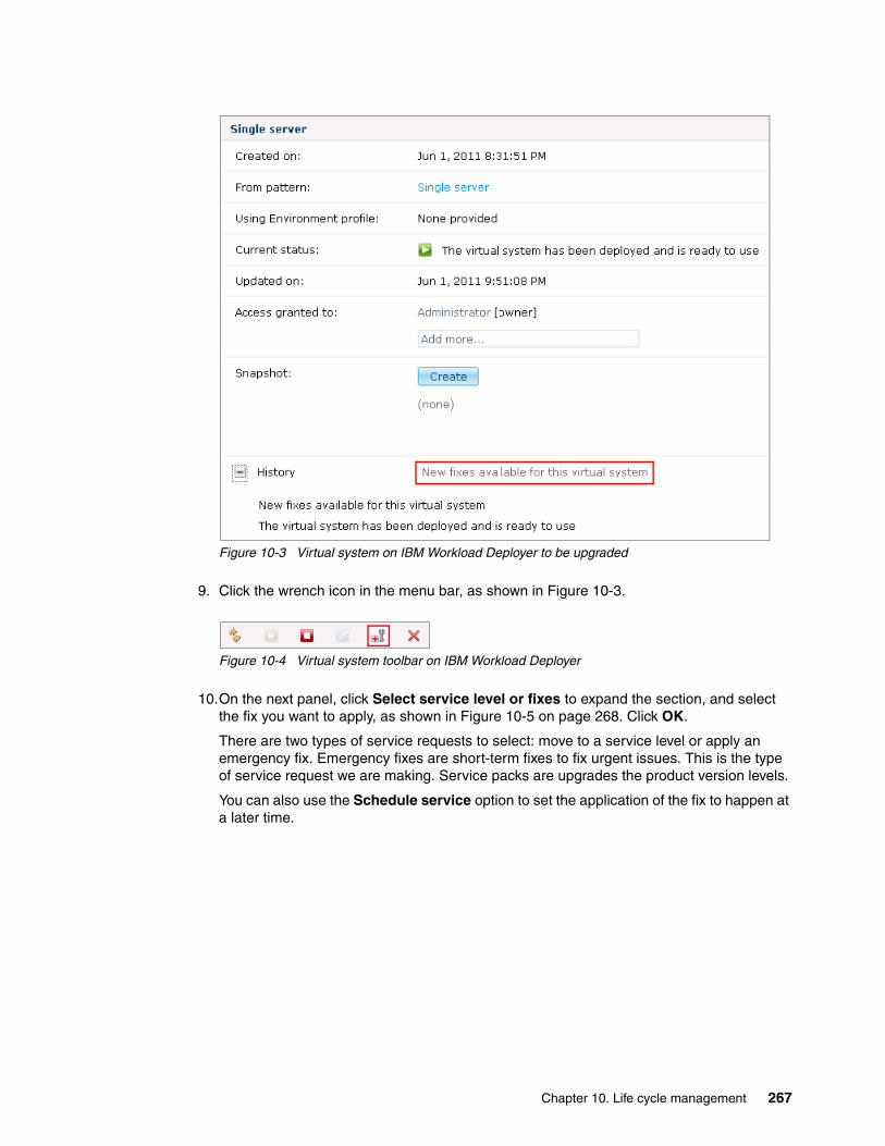
Figure 10-3 Virtual system on IBM Workload Deployer to be upgraded
9. Click the wrench icon in the menu bar, as shown in Figure 10-3.
Figure 10-4 Virtual system toolbar on IBM Workload Deployer
10.On the next panel, click Select service level or fixes to expand the section, and select the fix you want to apply, as shown in Figure 10-5 on page 268. Click OK.
There are two types of service requests to select: move to a service level or apply an emergency fix. Emergency fixes are short-term fixes to fix urgent issues. This is the type of service request we are making. Service packs are upgrades the product version levels.
You can also use the Schedule service option to set the application of the fix to happen at a later time.
Chapter 10. Life cycle management 267

Figure 10-5 Select emergency fix to apply to the virtual system
11.The appliance first shuts down each virtual machine in the virtual system and takes a snapshot of the entire system, enabling you to rollback to the current level if unexpected results occur after the update.
After the interim fix is applied to the WebSphere Application Server installations on each of the virtual machines in your virtual system, IBM Workload Deployer restarts the virtual machines and WebSphere Application Server components within those machines.
The status of the virtual system at the end of this process is shown in Figure 10-6 on page 269.
268 Virtualization with IBM Workload Deployer: Designing and Deploying Virtual Systems

Figure 10-6 Virtual system maintenance update completed
10.4 Applying maintenance with Rational Automation Framework for WebSphere
Rational Automation Framework for WebSphere can be used to apply fix packs across multiple systems to systems managed by IBM Workload Deployer and to systems outside of the IBM Workload Deployer domain. In this section, we use Rational Automation Framework for WebSphere to install a fix pack to a stand alone server. We first create a project to install a fix pack, FP17, to an existing WebSphere Application Server 7.0.0.15 virtual system provisioned using IBM Workload Deployer. We then apply that fix pack from Rational Automation Framework for WebSphere.
Restoring the previous version: Using the Restore button, shown in Figure 10-6, you can bring the system back to its state prior to the fix update. IBM Workload Deployer uses the snapshot it took of the virtual system prior to applying the update to do so.
Chapter 10. Life cycle management 269

For this example we download a new fix pack for WebSphere Application Server, create a new fix pack directory structure, and create a custom action for the installation process.
Extension of the framework is unnecessary for known fix packs because the media tree has placeholders and the actions are already created for these fix packs.
The following steps are demonstrated within this section:
1. Creating the RAFW cell definition using the Environment Wizard.2. Placing the latest Update Installer files in the media tree.3. Creating and populating a directory in the media tree for the fix pack installation files.4. Extending the framework with a custom action to apply a new fix pack.5. Adding a custom library (optional).6. Creating a project to install the fix pack.7. Installing the fix pack.
The following prerequisites are required to successfully complete these activities:
� Rational Automation Framework for WebSphere version 7.1.2.0 installation on Linux� A running WebSphere stand alone cell created using IBM Workload Deployer� The downloaded fix pack and Update Installer for WebSphere Application Server
For an example of this same process using a distributed cell with a Deployment Manager and multiple nodes, see:
� IBM Rational Automation Framework for WebSphere® Guided Activity: Applying fix packs to nodes in a WebSphere Application Server cell at:
http://www-01.ibm.com/support/docview.wss?uid=swg27017834&aid=1
10.4.1 Creating the RAFW cell definition using the Environment Wizard
In this step, we create a cell definition in Rational Automation Framework for WebSphere.
1. Open a web browser, and enter the address of the Rational Automation Framework for WebSphere server.
2. Log into the Rational Automation Framework for WebSphere interface using administrator credentials. For this example, Figure 10-7, the root user is used to gain access. Enter the required information into the Username and Password fields, and click Login.
Figure 10-7 Rational Automation Framework for WebSphere login box
3. Click the RAFW tab at the top right of the Rational Automation Framework for WebSphere home page, as shown in Figure 10-8 on page 271.
270 Virtualization with IBM Workload Deployer: Designing and Deploying Virtual Systems

Figure 10-8 Rational Automation Framework for WebSphere tabs
4. Enter the full path of the Rational Automation Framework for WebSphere installation on the server, and click Next. For this example, as shown in Figure 10-9, /opt/ibm/rational/buildforge/rafw is entered.
Figure 10-9 Rational Automation Framework for WebSphere system initialization Step 1
5. Click Validate to have the system verify the installation path. A successful validation results in the display of the panel shown in Figure 10-10. Click Next after the proper installation path is recorded.
Figure 10-10 Rational Automation Framework for WebSphere system initialization Step 2
6. Click Read an Existing Cell Configuration, as shown in Figure 10-11 on page 272, and enter the required information to perform this activity.
Chapter 10. Life cycle management 271

Figure 10-11 Rational Automation Framework for WebSphere read an existing cell Step 1
7. We name this new environment “ITSO”. Enter the following information into the form, as shown in Figure 10-12:
– Product or User Template: product– Environment Name: ITSO
Click Next.
Figure 10-12 Rational Automation Framework for WebSphere read an existing cell Step 2
8. Enter the required information in the next panel, as shown in Figure 10-13 on page 273:
– Existing Server Host Name: itso-cb-sys15
Enter the DNS server name for the Deployment Manager in the Existing Server Host Name field. For stand alone deployments, enter the DNS name of the stand alone server.
– OS Username: virtuser
– OS Password: itso4you
Click Validate to verify the that information is correct.
272 Virtualization with IBM Workload Deployer: Designing and Deploying Virtual Systems
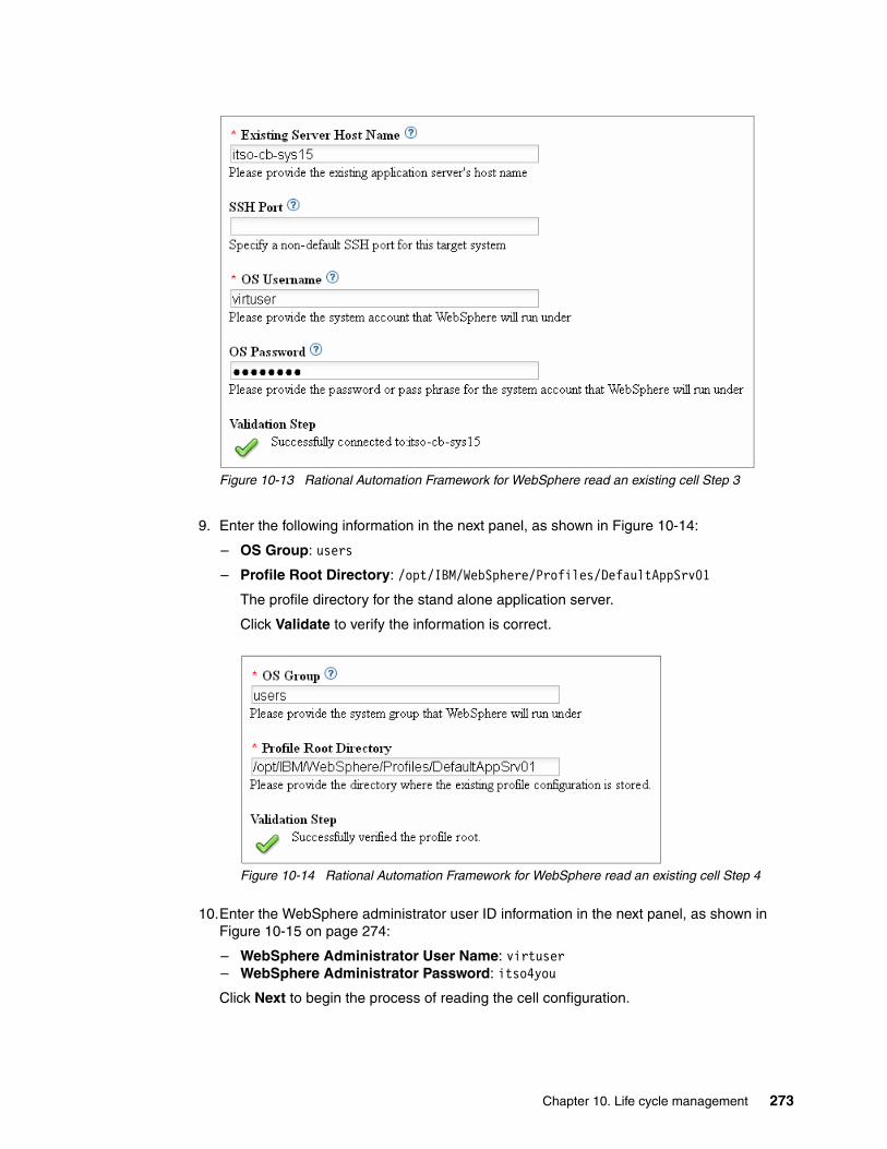
Figure 10-13 Rational Automation Framework for WebSphere read an existing cell Step 3
9. Enter the following information in the next panel, as shown in Figure 10-14:
– OS Group: users
– Profile Root Directory: /opt/IBM/WebSphere/Profiles/DefaultAppSrv01
The profile directory for the stand alone application server.
Click Validate to verify the information is correct.
Figure 10-14 Rational Automation Framework for WebSphere read an existing cell Step 4
10.Enter the WebSphere administrator user ID information in the next panel, as shown in Figure 10-15 on page 274:
– WebSphere Administrator User Name: virtuser– WebSphere Administrator Password: itso4you
Click Next to begin the process of reading the cell configuration.
Chapter 10. Life cycle management 273

Figure 10-15 Rational Automation Framework for WebSphere read an existing cell Step 5
11.Click Update Progress Output on the next page to view the current output of the read existing cell configuration process, as shown in Figure 10-16.
Figure 10-16 Rational Automation Framework for WebSphere update progress for read existing cell
The progress output provides information as to which steps are being executed including any associated results. An example of a successful reading of a cell configuration is shown in Figure 10-17.
Figure 10-17 Rational Automation Framework for WebSphere read existing cell complete
274 Virtualization with IBM Workload Deployer: Designing and Deploying Virtual Systems

When this process completes both an Environment and a Project for this cell are created. These can be viewed by selecting the respective menu items from the main Rational Automation Framework for WebSphere console. Figure 10-18 and Figure 10-19 show the resulting artifacts created during this example.
Figure 10-18 Rational Automation Framework for WebSphere read existing cell environment artifact
Figure 10-19 Rational Automation Framework for WebSphere read existing cell project artifact
10.4.2 Copying the most recent Update Installer image into the media tree
When you install WebSphere Application Server maintenance, you first must install the latest Update Installer. We copy the Update Installer install file to the media tree and make it available to Rational Automation Framework for WebSphere. Replace previous versions of the Update Installer that you downloaded.
The following steps assume that you downloaded the Update Installer to the system where Rational Automation Framework for WebSphere is installed:
1. Log into the Rational Automation Framework for WebSphere server as a user that has the privilege necessary to place files into the media tree. In this example, as shown in Figure 10-20, the root user is selected. The media tree is normally located within the RAFW_HOME/media directory.
Figure 10-20 Rational Automation Framework for WebSphere server login
2. Change to the Update Installer media tree directory, as shown in Figure 10-21 on page 276.
Chapter 10. Life cycle management 275

Figure 10-21 Rational Automation Framework for WebSphere update installer directory example
3. Extract the Update Installer archive, as shown in Figure 10-22.
Figure 10-22 Rational Automation Framework for WebSphere extract update installer image
Figure 10-23 shows the directory listing after these steps are complete.
Figure 10-23 Rational Automation Framework for WebSphere update installer directory listing
10.4.3 Copying the fix pack to the media tree
Next, we copy the fix pack to the media tree and make it available to Rational Automation Framework for WebSphere. The following steps assume that you downloaded the fix pack to the system where Rational Automation Framework for WebSphere is installed:
1. Log into the operating system as a user that has the privilege necessary to place files into the media tree. The media tree is normally located within the RAFW_HOME/media directory. In this example, the root user is selected. Open a command window.
2. Execute the mkdir command to create the new patch directory for the platform being used, as shown in Figure 10-24. For this example the patch directory is:
RAFW_HOME/media/linux/X32/was/70/patches/was70_fp17
Figure 10-24 Rational Automation Framework for WebSphere create fix pack directory
3. Change to the new patch directory, as shown in Figure 10-25.
Figure 10-25 Rational Automation Framework for WebSphere fix pack directory example
4. Copy the fix pack file to the new patch directory, as shown in Figure 10-26, using the cp command.
Figure 10-26 Rational Automation Framework for WebSphere copy fix pack to media tree
276 Virtualization with IBM Workload Deployer: Designing and Deploying Virtual Systems

Figure 10-27 shows the directory listing after these steps are complete.
Figure 10-27 Rational Automation Framework for WebSphere fix pack directory listing
10.4.4 Extending the framework for new fix pack releases
In this step, we extend the framework for the new fix pack by adding a new custom action to install the latest fix pack:
1. Determine the actions for install fix packs that are installed on your system.
If you are not sure what actions exist in your installation, use a grep command to list them:
RAFW_HOME/bin/rafw.sh -e environment -c cell -n node -l | grep was_70_install_fp
Look for entries that start with was_70_install_fp.
Figure 10-28 List the installed actions for installing a fix pack
2. Still at the command prompt, run the rafw.sh command, as shown in Figure 10-29. The purpose of this command is to print the Ant code for an existing action that installs a fix pack. We use the Ant code printed as a template for a new custom action to install a later fix pack.
For this example, the was_70_install_fp13 action is selected as a template, as shown in Figure 10-29.
Figure 10-29 Rational Automation Framework for WebSphere display Ant code command
In Figure 10-29:
– -e ITSO: The environment for the cell
– -c CloudBurstCell: The WebSphere Application Server cell
– -n CloudBurstNode: The WebSphere Application Server node
Do not extract or modify the fix pack: Do no extract or modify the fix pack. Doing so results in a failure to apply the fix pack to the WebSphere node.
Chapter 10. Life cycle management 277

– -p was_70_install_fp13: Displays the Ant code command output for the existing action was70_install_fp13.
Figure 10-30 shows the output for this example and displays the Ant code that is called to perform the action.
Figure 10-30 Rational Automation Framework for WebSphere fix pack 13 Ant code example
3. Modify the custom action install file to include the fix pack actions using the Ant code that is generated in the previous step to serve as a template:
a. Edit the RAFW_HOME/user/actions/install/was/70/custom_install_was70.xmlfile, and add the Ant code generated in the previous step to this file.
b. Modify the code for the new fix pack version. An example of the completed modification is shown in Figure 10-31 (changes in bold).
Figure 10-31 Rational Automation Framework for WebSphere custom install file modification
4. Run the rafw.sh command with the -list option to ensure that the new custom action is successfully created, as shown in Figure 10-32.
Figure 10-32 Rational Automation Framework for WebSphere Fix Pack 17 action listing
<project default="default" basedir="."> <description> Contains custom install tasks for WAS 70 Base </description>
<rafwaction location="remote,transfer" name="custom_was_70_install_fp17"/> <target depends="only_execute" description="Install WAS 7.0 fix pack 17" name="custom_was_70_install_fp17"> <antcall target="was_install_patch_was_to_level"> <param name="PATCH_NAME" value="was70_fp17"/> </antcall> </target>
</project>
Fix pack name: The fix pack name must have a prefix of custom to denote that a custom action was created.
278 Virtualization with IBM Workload Deployer: Designing and Deploying Virtual Systems

10.4.5 Adding a new library
This step is only necessary if the pre-installed Rational Automation Framework for WebSphere libraries do not provide all of the required functionality or need augmentation. For this example, a custom library is required to stop and start a single stand alone server. The RAFW_stop_servers and RAFW_start_servers libraries that start and stop servers in a distributed environment are provided with the product and are used as templates for our new library.
To create the library to stop the stand alone server:
1. Select the Libraries menu from the left panel of the browser menu, as shown in Figure 10-33.
Figure 10-33 Rational Automation Framework for WebSphere library menu selected
2. Enter RAFW_stop_servers in the Filter field, and click Filter.
Figure 10-34 Rational Automation Framework for WebSphere stop servers filter
3. Select the library editing button, as shown in Figure 10-35.
Figure 10-35 Rational Automation Framework for WebSphere edit this library button
4. Click Copy Library in the bottom right panel to create a clone of the current library, as shown in Figure 10-36.
Figure 10-36 Rational Automation Framework for WebSphere copy library
Chapter 10. Life cycle management 279

5. Select the library editing button, as shown in Figure 10-37 on page 280, to modify the new copy.
Figure 10-37 Rational Automation Framework for WebSphere edit copied library
6. Enter a name for the new library. For this example ITSO_stop_server is entered, as shown in Figure 10-38.
Figure 10-38 Rational Automation Framework for WebSphere copied library details
7. Select the Tags tab, and modify the Tag Format field, as shown in Figure 10-39. For this example ITSO_stop_server_$B is used. Click Save to make these changes permanent.
Figure 10-39 Rational Automation Framework for WebSphere copied library tags
8. Select the link for the new ITSO_stop_server library, as shown in Figure 10-40, to edit the command actions. Clear the filter box or change it to a different filter string to locate the new library.
Figure 10-40 Rational Automation Framework for WebSphere select new library link
Selecting this link causes a new page to be displayed where the steps and command actions can be modified. A portion of this panel is shown in Figure 10-41 on page 281. This library consists of one step that stops the application server.
Select the copy of the library for editing: Make sure that the copy of the library is selected for editing. Otherwise, changes might be made to the default library, which can create failure conditions for dependent projects.
280 Virtualization with IBM Workload Deployer: Designing and Deploying Virtual Systems

Figure 10-41 Rational Automation Framework for WebSphere new library steps and actions
9. Select the stop_server - servers link, as shown in Figure 10-41, to edit the step actions. Figure 10-42 shows the step action panel.
Figure 10-42 Rational Automation Framework for WebSphere edit step bottom right panel
10.Fill in the form with the following information:
– Name: stop_server - server
– Step Type: Regular
– Command: ${RAFW_HOME}/bin/rafw${SCRIPT_EXT} -env ${ENVIRONMENT} -cell ${CELL_NAME} -node ${BASE_NODE_NAME} -server ${BASE_SERVERS_ON_NODE} ${MODE} was_common_configure_stop_server
Leave all other values the same. An example of the completed form is shown in Figure 10-43 on page 282.
Chapter 10. Life cycle management 281

Figure 10-43 Rational Automation Framework for WebSphere completed step edit bottom right panel
11.Click Save Step to make these changes permanent.
A similar process is used to create the start_server - server library using the library created in the previous steps as a template. This action reduces the number of steps and changes necessary to create the new library.
To create the library to start the stand alone server:
1. Select the Libraries menu from the left panel of the browser menu. Enter ITSO_stop_server in the filter field, and click Filter, as shown in Figure 10-44.
Figure 10-44 Rational Automation Framework for WebSphere stop server filter
2. Select the library editing button, as shown in Figure 10-45.
Figure 10-45 Rational Automation Framework for WebSphere edit this library button
3. Click Copy Library to create a clone of the current library, as shown in Figure 10-46.
Figure 10-46 Rational Automation Framework for WebSphere copy library
282 Virtualization with IBM Workload Deployer: Designing and Deploying Virtual Systems

4. Select the library editing button, as shown in Figure 10-47, to modify the newly created copy.
Figure 10-47 Rational Automation Framework for WebSphere edit copied library
5. Enter the new name in the Name field. For this example ITSO_start_server is entered, as shown in Figure 10-48.
Figure 10-48 Rational Automation Framework for WebSphere copied library details
6. Select the Tags tab, as shown in Figure 10-49, and modify the Tag Format field. For this example ITSO_start_server_$B is used. Click Save to make these changes permanent.
Figure 10-49 Rational Automation Framework for WebSphere copied library tags
7. Select the link for the new library, as shown in Figure 10-50, to edit the command actions.
Figure 10-50 Rational Automation Framework for WebSphere select new library link
Selecting this link causes a new page to be displayed where the steps and command actions can be modified, as shown in Figure 10-51.
Figure 10-51 Rational Automation Framework for WebSphere new library steps and actions
8. Select the stop_server - server link, as shown in Figure 10-51, to edit the step actions. Figure 10-52 on page 284 shows the step action panel located in the lower right of the browser.
Chapter 10. Life cycle management 283

Figure 10-52 Rational Automation Framework for WebSphere edit step bottom right panel
9. Fill in the form with the following information:
Change the command so that it starts a server rather than stopping it.
– Name: start_server - server
– Command: ${RAFW_HOME}/bin/rafw${SCRIPT_EXT} -env ${ENVIRONMENT} -cell ${CELL_NAME} -node ${BASE_NODE_NAME} -server ${BASE_SERVERS_ON_NODE} ${MODE} was_common_configure_start_server
Leave all other values the same. An example of the completed form is shown in Figure 10-53.
Figure 10-53 Rational Automation Framework for WebSphere completed step edit bottom right panel
10.Click Save Step to make these changes permanent.
The ITSO_start_server and ITSO_stop_server libraries can now be used in Rational Automation Framework for WebSphere projects.
284 Virtualization with IBM Workload Deployer: Designing and Deploying Virtual Systems

10.4.6 Creating a project to apply the fix pack
To create a new project to apply the fix pack:
1. Select the Projects menu item.
2. Fill in the form in the Project Details tab with the following information, and click Save:
– Name: WAS_70_ApplyFixPack17 - stand alone– Environment: RAFW_ITSO_CloudBurstCell– Sticky: Sticky
The sticky option specifies that the steps in a project must all run on the same server.
In Figure 10-54, an example of the completed form is shown.
Figure 10-54 Rational Automation Framework for WebSphere project details tab
3. After saving, the project step editing panel is displayed, as shown in Figure 10-55 on page 286. The first step stops the stand alone server that is going to be updated. Enter the following values for the first step, and click Save Step:
– Name: Stop All Processes– Inline: ITSO_stop_server– Command: echo "Stop All Processes"– Timeout in Minutes: 0– Selector: - Default -– Result: RAFW
Chapter 10. Life cycle management 285

Figure 10-55 Rational Automation Framework for WebSphere project Step 1
4. Click Add Step at the top of the projects panel, as shown in Figure 10-56, to clear the form and begin creating the next step. This step uses the was_70_install_updateinstaller action to install the Update Installer.
Add the following values:
– Name: Update Installer
– Path: Absolute
– Command: ${RAFW_HOME}/bin/rafw${SCRIPT_EXT} -env ${ENVIRONMENT} -cell ${CELL_NAME} -node ${BASE_NODE_NAME} ${MODE} was_70_install_updateinstaller -transferMedia
– Timeout in Minutes: 0
– Selector: - Default -
– Result: RAFW
Figure 10-56 Rational Automation Framework for WebSphere add step button
Click Save Step.
Figure 10-57 on page 287 shows the completed project step.
286 Virtualization with IBM Workload Deployer: Designing and Deploying Virtual Systems

Figure 10-57 Rational Automation Framework for WebSphere project Step 2
5. Create a third project step by clicking Add Step, entering the following values, and clicking Save Step. This step uses the custom action we created to install the new fix pack:
– Name: Apply FP17
– Path: Absolute
– Command: ${RAFW_HOME}/bin/rafw${SCRIPT_EXT} -env ${ENVIRONMENT} -cell ${CELL_NAME} -node ${BASE_NODE_NAME} ${MODE} custom_was_70_install_fp17 -transferMedia
– Timeout in Minutes: 0
– Selector: - Default -
– Result: RAFW
Figure 10-58 on page 288 shows the completed form for this step.
Chapter 10. Life cycle management 287

Figure 10-58 Rational Automation Framework for WebSphere project Step 3
6. For the final step in this project the Clone Step feature is used to reduce the amount of time required to create the step. This step clones the stop step to create a start step that starts all the WebSphere processes after the fix pack is applied.
Hover over the Button Menu, as shown in Figure 10-59, for the Stop All Processes step to display the available options, as shown in Figure 10-60.
Figure 10-59 Rational Automation Framework for WebSphere project step button menu
Select the Clone To Bottom option to copy the step to the bottom of the list of project steps.
Figure 10-60 Rational Automation Framework for WebSphere project step button menu options
Figure 10-61 on page 289 shows the result of this operation, where a new step named Stop All Processes COPY 0 is now the last step in the project.
288 Virtualization with IBM Workload Deployer: Designing and Deploying Virtual Systems

Figure 10-61 Rational Automation Framework for WebSphere project step cloned to bottom
7. Select the Stop All Processes COPY 0 project step to display its details. Change the form, as shown in Figure 10-62. Click Save Step. Enter the following values:
– Name: Start All Processes– Inline: ITSO_start_server– Command: echo "Start All Processes"
Figure 10-62 Rational Automation Framework for WebSphere project Step 4
The remaining steps in this section modify the project Tags so that a meaningful identifier is used during project runs. The default tag format for any new project is BUILD_$B, where the variable indicates the project run number and increments automatically. Modifying this format allows easier tracking of the project status within the job listing:
1. Select the Projects menu from the left side of the web browser, and click Project Edit to the left of the WAS_70_ApplyFixPack17 - stand alone project, as shown in Figure 10-63.
Figure 10-63 Rational Automation Framework for WebSphere edit project button
2. Click the Tags tab, and modify the tag as indicated:
– Tag Format: WAS_70_ApplyFixPack17 - Standalone_$B
Chapter 10. Life cycle management 289

Figure 10-64 shows the updated Tags form.
Figure 10-64 Rational Automation Framework for WebSphere updated tag format
Click Save.
We created the project to apply fix pack 17 to a stand alone application server. The next step is to execute the project.
10.4.7 Applying the fix pack
Now, we apply the fix pack to the stand alone WebSphere Application Server using the project we created:
1. Log into the Rational Automation Framework for WebSphere interface using administrator credentials.
2. Select the Projects menu from the panel on the left hand side, and click the WAS_70_ApplyFixPack17 - stand alone link shown in Figure 10-65.
Figure 10-65 Rational Automation Framework for WebSphere projects menu
The project management panel shown in Figure 10-66 opens.
Figure 10-66 Rational Automation Framework for WebSphere project management window
3. Click Start Project at the top of this panel to begin the job execution process. A new panel will display that allows customization of the project invocation parameters. Two tabs are available that provide separate customization options. The default tab is Job Details, as shown in Figure 10-67 on page 291, and the other tab is Job Steps.
290 Virtualization with IBM Workload Deployer: Designing and Deploying Virtual Systems

Figure 10-67 Rational Automation Framework for WebSphere job details
For this example, only the Job Details tab is used. The Job Steps functionality is useful if there is a requirement to invoke only certain portions of a more complex job (for example, start server) or if a restart of a failed job is necessary.
4. Click Execute to start this project. Prior to performing this action, verify that the following fields and values are correct:
– MODE: Execute– MEDIA_TRANSFER: Transfer Media
After the job starts, a new page is displayed that provides information about the current project status, including details for each step, as shown in Figure 10-68.
Figure 10-68 Rational Automation Framework for WebSphere project status
5. Selecting a job step link allows you to view the messages that are associated with the execution of the project step. For this example, the Apply FP17 link is selected, as shown in Figure 10-69 on page 292.
Chapter 10. Life cycle management 291

Figure 10-69 Rational Automation Framework for WebSphere project job step detailed messages
6. Select the job link at the top of the job step page to return to the job status menu, as shown in Figure 10-70.
Figure 10-70 Rational Automation Framework for WebSphere job status link
The final status of the project execution can be viewed in two ways. One is to use the Jobs menu. Figure 10-71 shows a successful completion status using this process.
Figure 10-71 Rational Automation Framework for WebSphere project status using the jobs menu
The second option is to review the project status from the Home Completed Runs menu that is shown in Figure 10-72 on page 293. The main difference between the two options is that one shows the result of each job step while the other indicates only the status of the project as a whole.
292 Virtualization with IBM Workload Deployer: Designing and Deploying Virtual Systems

Figure 10-72 Rational Automation Framework for WebSphere project status using the completed runs menu
7. To validate the fix pack update, we can use the versionInfo.sh command on the WebSphere Application Server that is running virtual system itself. Figure 10-73 shows the invocation and sample output from this command, indicating a successful application of the fix pack.
Figure 10-73 Sample output from the versionInfo.sh command
10.5 Managing images and patterns: Strategic approach
While the tactical approach for updating and maintaining IBM Workload Deployer environments applies to running virtual systems, the strategic approach relates to updating
[virtuser@itso-cb-sys15 ~]$ /opt/IBM/WebSphere/AppServer/bin/versionInfo.shWVER0010I: Copyright (c) IBM Corporation 2002, 2005, 2008; All rights reserved.WVER0012I: VersionInfo reporter version 1.15.1.26, dated 8/9/08
--------------------------------------------------------------------------------IBM WebSphere Application Server Product Installation Status Report--------------------------------------------------------------------------------
Report at date and time June 8, 2011 6:55:18 PM UTC
Installation--------------------------------------------------------------------------------Product Directory /opt/IBM/WebSphere/AppServerVersion Directory /opt/IBM/WebSphere/AppServer/properties/versionDTD Directory /opt/IBM/WebSphere/AppServer/properties/version/dtdLog Directory /opt/IBM/WebSphere/AppServer/logsBackup Directory /opt/IBM/WebSphere/AppServer/properties/version/nif/backupTMP Directory /tmp
...
Installed Product--------------------------------------------------------------------------------Name IBM WebSphere Application Server - NDVersion 7.0.0.17ID NDBuild Level cf171115.15Build Date 4/16/11Architecture Intel (32 bit)
--------------------------------------------------------------------------------End Installation Status Report--------------------------------------------------------------------------------[virtuser@itso-cb-sys15 ~]$
Chapter 10. Life cycle management 293

and maintaining images and patterns. The benefit of this approach is that all subsequent deployments of the extended image and pattern contain the updates.
Figure 10-74 shows the process for extending and updating a virtual image.
Figure 10-74 Strategic approach to update virtual images
The process of extending a virtual images involves the following steps:
1. Clone an existing virtual image.
2. Deploy the new image to the cloud.
3. Apply the updates to the deployed virtual system.
4. Capture the new updated image into the catalog.
5. Create new custom patterns (or clone your existing custom patterns), and select this new image as the basis for your patterns.
10.5.1 Extending a virtual image to apply maintenance
To extend a virtual image to create a newly updated image for use in patterns:
1. Choose a virtual image to customize. From the IBM Workload Deployer user interface (UI), select Catalog Virtual Images.
2. Select the image, and click Clone and extend, as illustrated in Figure 10-75 on page 295.
1. Clonevirtual image
5. Updatedvirtual image
can be redeployed
4. Capturevirtual system
3. Apply maintenance
2. Deployvirtual imageto the cloud
Stand aloneNode
294 Virtualization with IBM Workload Deployer: Designing and Deploying Virtual Systems

Figure 10-75 Clone and extend virtual image to be updated
3. Enter a Name and Version for the new image you are creating:
– Name: WebSphere Application Server 7.0.0.11 with ifixes 22533 and 34841– Version: 7.0.0.11.1
Figure 10-76 Naming the virtual image that is being extended
In the optional Deployment configuration section, you can specify the cloud group for the virtual system to be deployed and the password for the virtuser. Similarly, using the Hardware configuration (optional) tab you can customize hardware parameters, such as
Chapter 10. Life cycle management 295

disk space, memory allocation, and so on, for the virtual system to be deployed. We leave these sections as they are, and click OK.
4. IBM Workload Deployer creates and deploys a pattern based on the extended image that you defined. The resulting virtual system’s name is a combination of the name that you provided for your new virtual image along with the version you specified as highlighted in Figure 10-77.
Figure 10-77 Virtual image cloning and extension complete
5. Navigate to Instances Virtual Systems, and select the newly deployed virtual system created as part of the image extension.
6. Click Apply service, as shown in Figure 10-78 on page 297.
296 Virtualization with IBM Workload Deployer: Designing and Deploying Virtual Systems
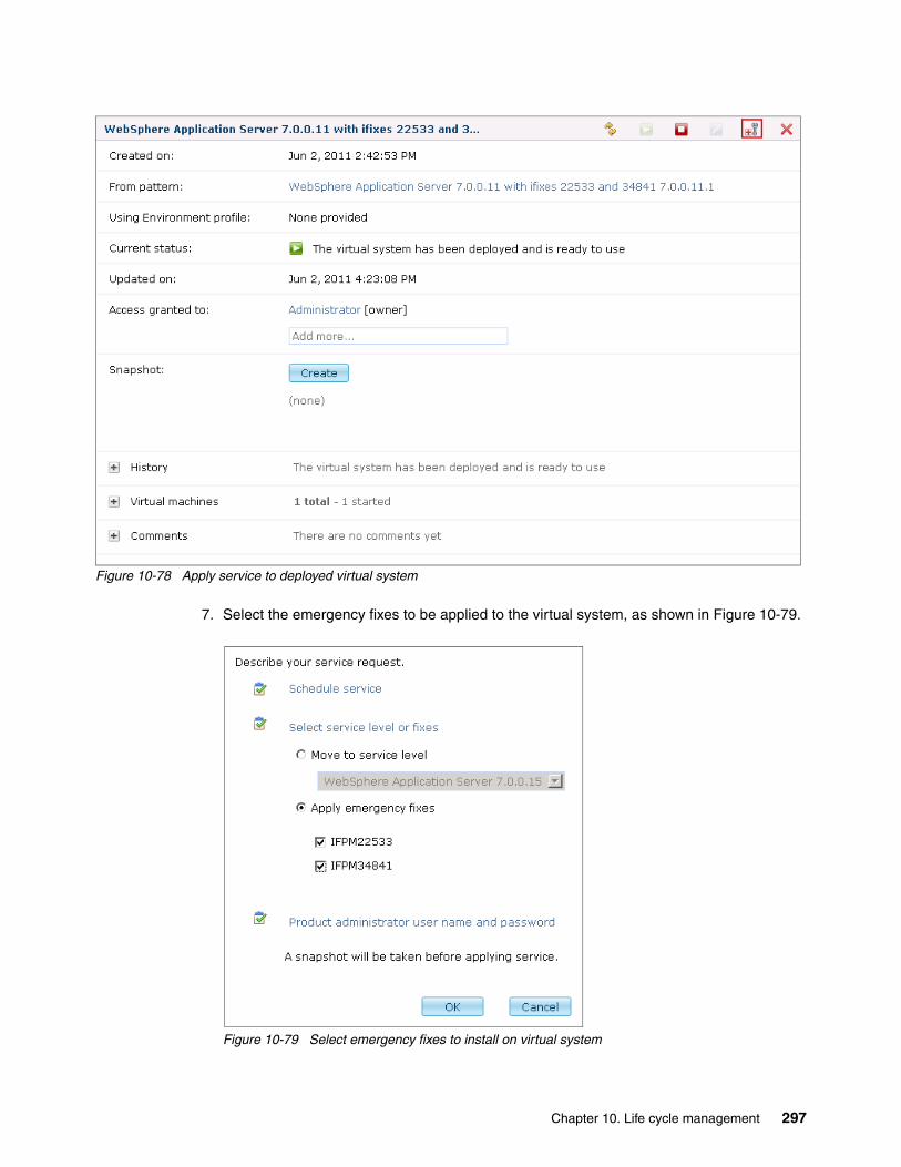
Figure 10-78 Apply service to deployed virtual system
7. Select the emergency fixes to be applied to the virtual system, as shown in Figure 10-79.
Figure 10-79 Select emergency fixes to install on virtual system
Chapter 10. Life cycle management 297

8. Upon a successful installation of the emergency fixes on the virtual system, the service history will look like Figure 10-80.
Figure 10-80 Emergency fixes successfully installed on virtual system
9. Now that the emergency fixes are applied, the virtual machine can be captured and stored in the catalog as a new virtual image. To do this, navigate back to the Catalog Virtual Images section in the IBM Workload Deployer UI, and select the virtual image that was cloned and extended. Capture the image by clicking Capture in the menu bar, as shown in Figure 10-81 on page 299.
Making the fixes available: The emergency fixes listed in Figure 10-79 on page 297 were previously added to the catalog in the same way described in Section 10.3, “Applying maintenance with IBM Workload Deployer” on page 265.
298 Virtualization with IBM Workload Deployer: Designing and Deploying Virtual Systems

Figure 10-81 Capturing the updated virtual image back into the catalog
10.After the capture is done, lock down the image using the Make read-only icon, as shown in Figure 10-82 on page 300, to prevent further changes to it.
Chapter 10. Life cycle management 299

Figure 10-82 Successful capture and locking of virtual image
11.You can now create a new pattern based on the new image.
Browse to Patterns Virtual Systems, and locate a pattern based on the virtual image without the emergency fixes. Click the Clone icon in the upper-right corner of the toolbar, as shown in Figure 10-83 on page 301.
300 Virtualization with IBM Workload Deployer: Designing and Deploying Virtual Systems
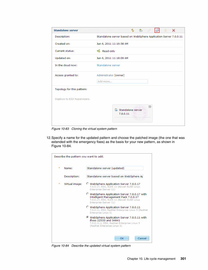
Figure 10-83 Cloning the virtual system pattern
12.Specify a name for the updated pattern and choose the patched image (the one that was extended with the emergency fixes) as the basis for your new pattern, as shown in Figure 10-84.
Figure 10-84 Describe the updated virtual system pattern
Chapter 10. Life cycle management 301

13.Upon completion, the updated pattern will look like Figure 10-85. Note the extended image version reference (7.0.0.11.1). Deploy the pattern to the cloud using the corresponding icon in the toolbar.
Figure 10-85 Deploying the updated virtual system pattern
After the newly deployed virtual system is tested successfully, the transition from the old system to the new can happen transparently to the end user.
10.5.2 Importing and exporting virtual images
There are times when you must import and export virtual images to and from the IBM Workload Deployer appliance. The virtual images can be base or image updates from IBM or customized images that you created that you want to deploy to other appliances.
Importing an imageTo import an image to the appliance:
1. Navigate through the Catalog Virtual Images menu, and click New (+).
2. Specify the URL to the Open Virtual Appliance (OVA) file to import and optionally a username and password if the location of the new virtual image is secured, as illustrated in Figure 10-86 on page 303. Click OK.
Getting new OVA images: OVA images by IBM are generally available for download by customers through the Passport Advantage® channel and by business partners through Partnerworld.
302 Virtualization with IBM Workload Deployer: Designing and Deploying Virtual Systems

Figure 10-86 Importing a virtual image to the appliance
3. The import task starts and is placed in the task queue. After a successful import, the imported virtual image will appear in the catalog giving you the opportunity to accept the license agreement for the various components that make up the image, as illustrated in Figure 10-87.
Figure 10-87 Accepting license agreement on imported image
Chapter 10. Life cycle management 303
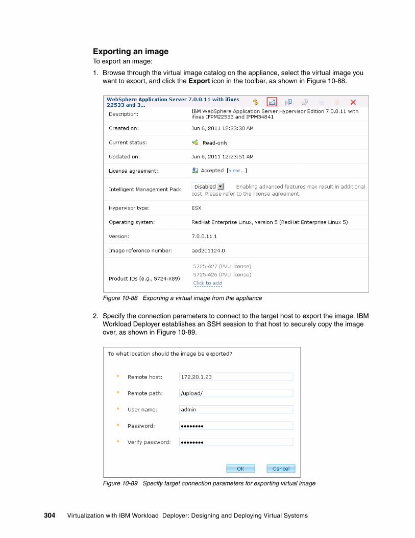
Exporting an imageTo export an image:
1. Browse through the virtual image catalog on the appliance, select the virtual image you want to export, and click the Export icon in the toolbar, as shown in Figure 10-88.
Figure 10-88 Exporting a virtual image from the appliance
2. Specify the connection parameters to connect to the target host to export the image. IBM Workload Deployer establishes an SSH session to that host to securely copy the image over, as shown in Figure 10-89.
Figure 10-89 Specify target connection parameters for exporting virtual image
304 Virtualization with IBM Workload Deployer: Designing and Deploying Virtual Systems

3. If email notification is enabled in the profile for the user issuing the export command, a confirmation email, with the results of the operation, is received when the task completes. The logs on the appliance can also be checked to verify whether the export completed successfully.
10.6 Managing application updates
In addition to updating the virtual images, patterns, and running virtual systems, IBM Workload Deployer simplifies the delivery of application updates into the environments managed by the appliance. Generally, script packages are invoked towards the end of the pattern deployment process. However, you can declare user-initiated script packages, which can be invoked from the IBM Workload Deployer UI interactively at any time and as often as needed.
In this example, a script package consisting of wsadmin commands to uninstall an application, then install a new updated version of the application are added to the pattern:
1. Create a script package with the wsadmin commands required to upgrade an installed application. The current application, simple_v1, is uninstalled by the script package and an updated version of the application, called simple_v2, is installed.
2. Upload the script packages to the IBM Workload Deployer catalog using the process outlined in 6.1, “Uploading the script packages” on page 108.
3. Navigate to Catalog Script packages, and click the new script package to open it. Set the Executes: field to “when I initiate it” as shown in Figure 10-90 on page 306, so the script can be executed manually.
Chapter 10. Life cycle management 305
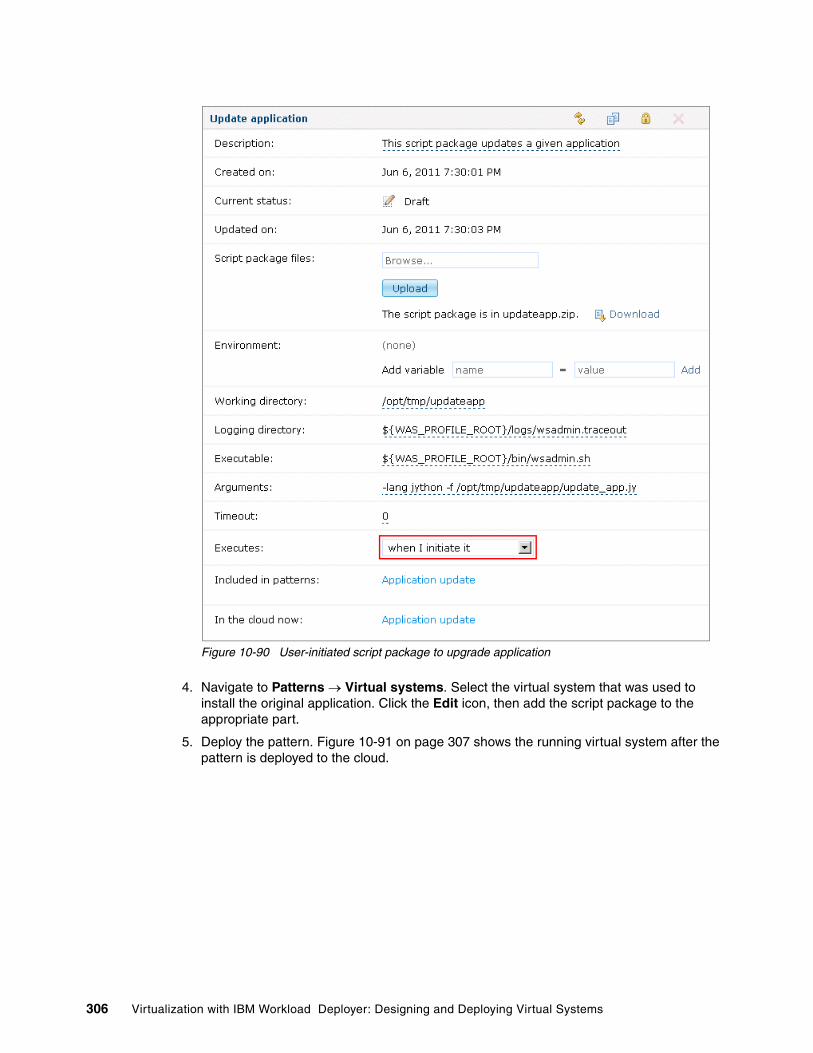
Figure 10-90 User-initiated script package to upgrade application
4. Navigate to Patterns Virtual systems. Select the virtual system that was used to install the original application. Click the Edit icon, then add the script package to the appropriate part.
5. Deploy the pattern. Figure 10-91 on page 307 shows the running virtual system after the pattern is deployed to the cloud.
306 Virtualization with IBM Workload Deployer: Designing and Deploying Virtual Systems

Figure 10-91 Virtual system with user-initiated script package
6. Prior to running the script, note the version of the application running on the WebSphere Application Server administration console, as highlighted in Figure 10-92 on page 308.
Chapter 10. Life cycle management 307

Figure 10-92 Simple application Version 1
7. To run the user initiated script, return to the virtual systems page shown in Figure 10-91 on page 307, and click Execute now.
8. The script upgrades the application and the results are reflected in the WebSphere Application server administration console.
Figure 10-93 Simple application upgraded to Version 2
10.7 Managing the appliance
In 2.12, “Appliance settings” on page 31, we provided an introduction to the IBM Workload Deployer appliance settings. In this section, we cover the backup and restore and firmware update functionality in more detail because they serve an important part in the appliance life cycle management.
10.7.1 Backup and restore
The backup and restore process, available with the Appliance Settings menu of the appliance, as shown in Figure 10-94 on page 309, allows you to capture an IBM Workload Deployer environment at any given point-in-time. You can then either restore that environment on the appliance from which it was taken or restore it on another appliance.
308 Virtualization with IBM Workload Deployer: Designing and Deploying Virtual Systems

Figure 10-94 Backup and restore options
The backup and restore process can be broken down into five steps, shown in Figure 10-94:
1. Storing your certificate and private key:
Though the certificate containing the public key pair is stored on IBM Workload Deployer, the certificate and private key must be stored in a safe location:
a. Specify a host name.
b. Specify the path where the files are to be stored.
c. Specify the user name to access the host.
d. Click Edit to specify the password to access the host. Click Submit to enter the password.
Click Test connection to ensure that you have connectivity to the host.
Figure 10-95 on page 310 shows the storing key pair for backup.
Chapter 10. Life cycle management 309

Figure 10-95 Storing key pair for backup
2. Generating or uploading your certificate and private key:
To protect the sensitive information that exists in your backup images, the Rivest, Shamir, and Adleman (RSA) encryption is used. The certificate and private key protect your sensitive information as you back it up and restore it. The certificate and private key must either be provided or generated.
Figure 10-96 shows the generating or uploading key pair.
Figure 10-96 Generating or uploading key pair
3. Configuring backup storage:
A backup storage location for the backup artifacts is required before you can schedule a backup image to be taken. This profile also provides the required parameters for establishing authentication to an external server with a Secure Shell (SSH) daemon running.
Figure 10-97 on page 311 illustrates generating or uploading the key pair.
310 Virtualization with IBM Workload Deployer: Designing and Deploying Virtual Systems

Figure 10-97 Configuring backup storage
4. Enabling or disabling backups:
You can schedule backups of your IBM Workload Deployer environment to begin immediately or repeatedly at hourly time intervals, as shown in Figure 10-98.
Figure 10-98 Enabling or disabling backups
5. Restoring to a previous time:
The Workload Deployer appliance can be returned to a specific state by restoring from a backup image. The backup image is decrypted and streamed onto the appliance to return IBM Workload Deployer to a previous state, as shown in Figure 10-99 on page 312.
Chapter 10. Life cycle management 311

Figure 10-99 Restoring to a previous time
10.7.2 Firmware updates
You can update the firmware of the appliance by downloading a new update from IBM Fix Central at:
http://www.ibm.com/support/fixcentral
1. Go to IBM Fix Central, and download a firmware update to your local file system. This file is signed to ensure the integrity of the update being performed.
2. Expand Appliance Settings Firmware. The current installed firmware level on the appliance is displayed.
Figure 10-100 Appliance firmware update
3. Click Browse to search the local file system for the new firmware update file you downloaded.
4. Click Upgrade when ready.
The actual firmware update takes an average of about 10 to 15 minutes after it begins, but can possibly take longer.
312 Virtualization with IBM Workload Deployer: Designing and Deploying Virtual Systems
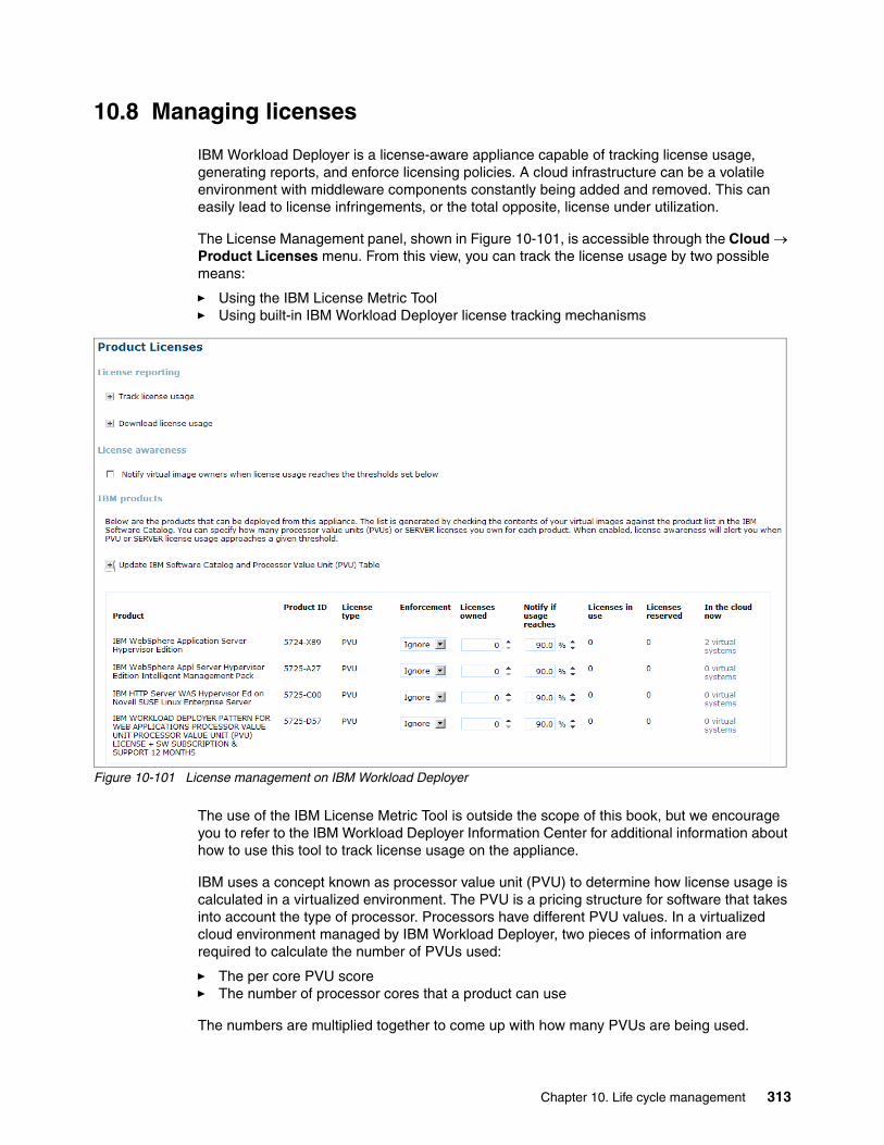
10.8 Managing licenses
IBM Workload Deployer is a license-aware appliance capable of tracking license usage, generating reports, and enforce licensing policies. A cloud infrastructure can be a volatile environment with middleware components constantly being added and removed. This can easily lead to license infringements, or the total opposite, license under utilization.
The License Management panel, shown in Figure 10-101, is accessible through the Cloud Product Licenses menu. From this view, you can track the license usage by two possible means:
� Using the IBM License Metric Tool� Using built-in IBM Workload Deployer license tracking mechanisms
Figure 10-101 License management on IBM Workload Deployer
The use of the IBM License Metric Tool is outside the scope of this book, but we encourage you to refer to the IBM Workload Deployer Information Center for additional information about how to use this tool to track license usage on the appliance.
IBM uses a concept known as processor value unit (PVU) to determine how license usage is calculated in a virtualized environment. The PVU is a pricing structure for software that takes into account the type of processor. Processors have different PVU values. In a virtualized cloud environment managed by IBM Workload Deployer, two pieces of information are required to calculate the number of PVUs used:
� The per core PVU score� The number of processor cores that a product can use
The numbers are multiplied together to come up with how many PVUs are being used.
Chapter 10. Life cycle management 313

As an example, we have two physical machines in the cloud, each with two dual-core processors, making a total of four cores per physical machine, as shown in Figure 10-102. In the example, assume that each core has a PVU value of 120.
Figure 10-102 Physical servers in cloud
Four virtual machines are placed in the cloud, two with two virtual processors and one with a single virtual processor (or core), as shown in Figure 10-103.
Figure 10-103 Virtual machines in the cloud
The total PVU usage is PVU score x the number of cores in use. In our situation, these values are 120 x 5 = 600.
Another four virtual machines are deployed, three with two virtual processors and one with a single virtual processor, as shown in Figure 10-104.
Figure 10-104 More virtual machines in the cloud
The PVU usage for this scenario is 120 x 8 = 960. The PVU license usage value cannot exceed the number of cores on the physical hardware, no matter how many virtual machines are deployed.
Machine 1 Machine 2
4 Cores4 Cores
Machine 1 Machine 2
vm1 vm2 vm3 vm4
vm5
Machine 1 Machine 2
vm1
vm6
vm2 vm3 vm4
vm7
314 Virtualization with IBM Workload Deployer: Designing and Deploying Virtual Systems

To help better understand, let us add another physical machine to the cloud, which has two dual-core processors, four cores in total, as shown in Figure 10-105.
Figure 10-105 Extra physical machine in the cloud
The PVU usage depends on where the virtual machines are located. In the scenario depicted in Figure 6-62, the PVU license usage is still 960. If vm7, which contains a single virtual processor, is moved to machine3, as shown in Figure 10-106, the PVU license usage changes and becomes 120 x 9 = 1080. This is because all virtual machines running in the cloud now have access to a total of nine cores.
Figure 10-106 Virtual machine move
During deployment of a new virtual system, WebSphere CloudBurst Appliance analyzes the running systems in the cloud and uses an algorithm that attempts to minimize PVU usage and balance workloads across physical machines in the cloud.
10.8.1 Tracking maximum usage
You can track the maximum usage, also known as high water usage, for each product being dispensed by IBM Workload Deployer from the Download License usage view, as shown in Figure 10-107 on page 316.
Note: For more information about PVU licensing refer to:
http://www-01.ibm.com/software/lotus/passportadvantage/pvu_licensing_for_customers.html
http://www-01.ibm.com/software/lotus/passportadvantage/Counting_Software_licenses_using_specific_virtualization_technologies.html
vm5
Machine 1 Machine 2 Machine 3
vm1
vm6
vm2 vm3 vm4
vm7
vm5
Machine 1 Machine 2 Machine 3
vm1
vm6
vm2 vm3 vm4 vm7
Chapter 10. Life cycle management 315
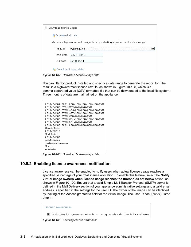
Figure 10-107 Download license usage data
You can filter by product installed and specify a date range to generate the report for. The result is a highwatermarklicense.csv file, as shown in Figure 10-108, which is a comma-separated value (CSV) formatted file that can be downloaded to the local file system. Three months of data are maintained on the appliance.
Figure 10-108 Download license usage data
10.8.2 Enabling license awareness notification
License awareness can be enabled to notify users when actual license usage reaches a specified percentage of your total license allocation. To enable this feature, select the Notify virtual image owners when license usage reaches the thresholds set below option, as shown in Figure 10-109. Ensure that a valid Simple Mail Transfer Protocol (SMTP) server is defined in the Mail Delivery section of your appliance administrative settings and a valid email address is specified in the settings for the user ID. The owner of the image can be identified by looking at the Access granted to field for the virtual image. The user ID has [owner] listed after it.
Figure 10-109 Enabling license awareness
316 Virtualization with IBM Workload Deployer: Designing and Deploying Virtual Systems
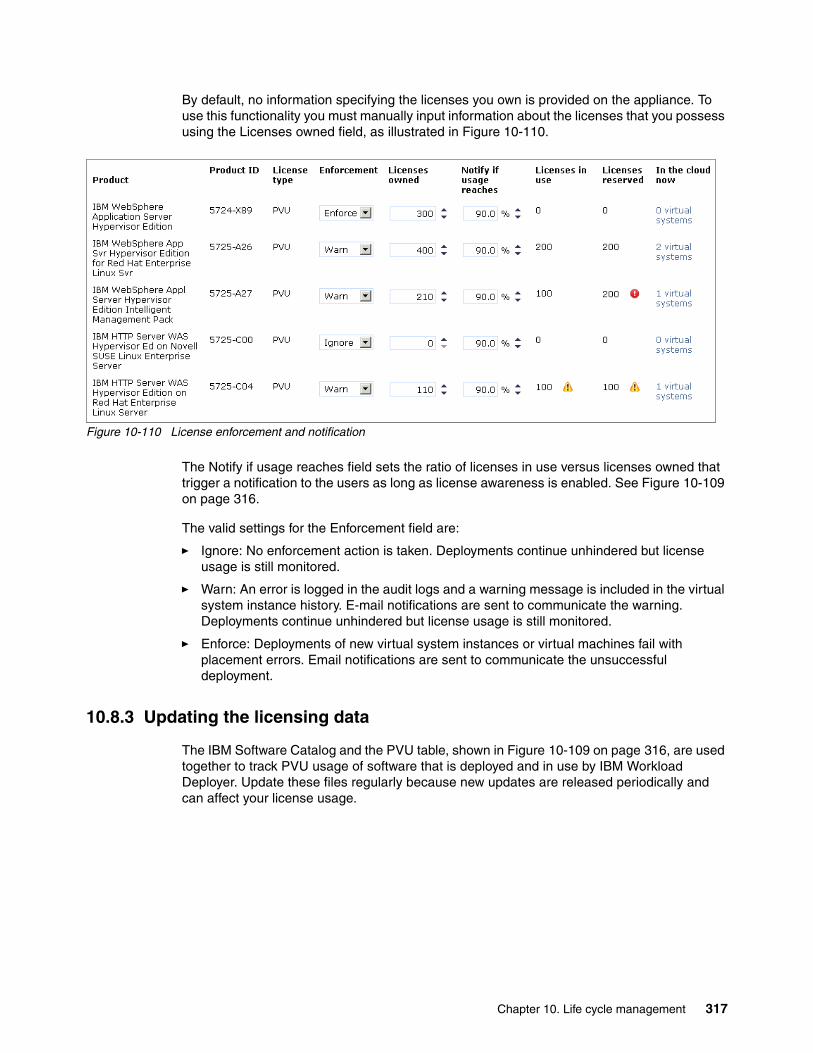
By default, no information specifying the licenses you own is provided on the appliance. To use this functionality you must manually input information about the licenses that you possess using the Licenses owned field, as illustrated in Figure 10-110.
Figure 10-110 License enforcement and notification
The Notify if usage reaches field sets the ratio of licenses in use versus licenses owned that trigger a notification to the users as long as license awareness is enabled. See Figure 10-109 on page 316.
The valid settings for the Enforcement field are:
� Ignore: No enforcement action is taken. Deployments continue unhindered but license usage is still monitored.
� Warn: An error is logged in the audit logs and a warning message is included in the virtual system instance history. E-mail notifications are sent to communicate the warning. Deployments continue unhindered but license usage is still monitored.
� Enforce: Deployments of new virtual system instances or virtual machines fail with placement errors. Email notifications are sent to communicate the unsuccessful deployment.
10.8.3 Updating the licensing data
The IBM Software Catalog and the PVU table, shown in Figure 10-109 on page 316, are used together to track PVU usage of software that is deployed and in use by IBM Workload Deployer. Update these files regularly because new updates are released periodically and can affect your license usage.
Chapter 10. Life cycle management 317

Figure 10-111 Updating IBM software catalog and PVU table
318 Virtualization with IBM Workload Deployer: Designing and Deploying Virtual Systems

Chapter 11. Monitoring and troubleshooting environment
In this chapter, we discuss tools that you can use to monitor and troubleshoot a virtual system.
This chapter includes the following topics:
� 11.1, “IBM Tivoli Monitoring to monitor deployed images” on page 320� 11.2, “Simple Network Management Protocol monitoring” on page 326� 11.3, “Troubleshooting procedures” on page 328
11
© Copyright IBM Corp. 2011. All rights reserved. 319

11.1 IBM Tivoli Monitoring to monitor deployed images
IBM Tivoli Monitoring software is designed to monitor your IT infrastructure and applications and to alert you when incidents occur. IBM Tivoli Monitoring can also respond automatically to events as specified by the user. IBM Tivoli Monitoring can detect and correct system problems quickly, reducing or eliminating the impact to the end users. IBM Tivoli Monitoring also collects data so that it can be used to analyze the performance and capacity planning activities.
Key functions of this tool include:
� IBM Tivoli Monitoring recognizes and responds quickly to problems, helping your team meet the terms of Service Level Agreements (SLAs). A history of incidents can be created to provide assistance in researching and tracking incidents.
� Using IBM Tivoli Monitoring you can set thresholds so that you can detect when an abnormal situation is about to occur.
� IBM Tivoli Monitoring can provide reports that are useful for capacity planning.
� IBM Tivoli Monitoring provides the system operators with the tools to analyze data, including tools to visualize the data, the use of common data and reporting, and best practice advice to the operator in response to incidents.
11.1.1 Components
An IBM Tivoli Monitoring environment includes the components shown in Figure 11-1.
Figure 11-1 Sample Diagram of Cloud Monitoring System with IBM Tivoli Monitoring
Tivoli EnterprisePortal Server
Hub TivoliEnterprise
Monitoring ServerTEMS
DB
TEMSDB
TEMSDB
Remote TivoliEnterprise
Monitoring Server
Deployed image
Agent
Deployed image
Agent
Deployed image
Agent
Deployed image
Agent
Deployed image
Agent
Deployed image
Agent
Deployed image
Agent
Deployed image
Agent
320 Virtualization with IBM Workload Deployer: Designing and Deploying Virtual Systems

Tivoli Enterprise Monitoring ServerTivoli Enterprise Monitoring Server (also called the monitoring server), is the key component in the IBM Tivoli Monitoring environment. There are two types of monitoring server: a hub monitoring server (also referred to as the main monitoring server) and optional remote monitoring servers. There must be at least one hub monitoring server, and there can be several optional remote monitoring servers. The main function of the hub monitoring server is to collect data from Tivoli Enterprise Management agents and remote monitoring servers in the environment. Both the hub monitoring server and remote monitoring servers provide data to the Tivoli Enterprise Portal.
Tivoli Enterprise Management agentsA Tivoli Enterprise Management agent must be installed in each host where monitoring occur.s The agents provide the following function:
� Collect data from operating systems, applications, and databases to be monitored by the Tivoli Enterprise Monitoring Server.
� Evaluate situations or conditions that are configured to the Tivoli Enterprise Monitoring Server, and then take action when those situations or conditions occur.
� When a situation or condition is evaluated, the agent sends data and alerts to the monitoring server.
There are two ways to implement the agent technology:
� Agent-based technology
An agent is installed in the monitored system. This is the method used in our scenario. The agent is installed with a script that is added to the pattern for the virtual system (See “The itmagentconfig.zip” on page 109.)
� Agentless technology
No agent is installed on the monitored system. The monitoring server uses a remote application programming interface (API). Examples of the use of this technology include:
– Simple Network Management Protocol (SNMP)– Java Management Extensions (JMX)– Common Interface Model (CIM)– Windows Management Instrumentation (WMI)
Tivoli Enterprise Portal ServerThe Tivoli Enterprise Portal provides a user interface to the Tivoli Enterprise Monitoring Server. The Tivoli Enterprise Portal can be installed in the same server as the monitoring server or on a separate system.
Figure 11-2 on page 322 shows the Tivoli Enterprise Portal.
Chapter 11. Monitoring and troubleshooting environment 321

Figure 11-2 Tivoli Enterprise Portal
The Navigator provides a physical view of your monitored network, organized by operating system platform, system type, Tivoli Enterprise Monitoring product (agents), and the attribute groups from which the agents can collect information.
As you deploy virtual systems from the IBM Workload Deployer that have the IBM Tivoli Monitoring (ITM) agent installed, entries for those systems appear in the Navigator. The agent used in our scenarios is a monitoring agent for Linux. It provides insight into aspects of the operating system, such as disk usage, system capacity, file sizes, and other information that can help you understand the performance of your system.
11.1.2 Fault management
Fault management is about managing situations, conditions, alerts, and actions in IBM Tivoli Monitoring. There are several ways that these conditions are recognized:
� Comparing one or several metrics with its corresponding thresholds. This is called a situation. Situations define conditions that you want to be alerted to.
� Checking whether several situations are triggered simultaneously.
� Checking whether a situation is triggered at different agents simultaneously.
� Adaptives, based on specific schedules, destinations, or calculating baselines.
322 Virtualization with IBM Workload Deployer: Designing and Deploying Virtual Systems

Situations are key to fault management. A situation is a test for certain conditions on managed systems. When the conditions are met, an event occurs, and if defined to the situation, a take action command is carried out. The products that run in the Tivoli Monitoring environment come with their own set of situations that can be used as is, and can serve as models for defining custom situations.
Situations are defined under the Process category for the operating system, as shown in Figure 11-3.
Figure 11-3 Open the situations list for the selected item in the Navigator
Selecting Situations opens the panel in Figure 11-4 on page 324.
Chapter 11. Monitoring and troubleshooting environment 323

Figure 11-4 Situation panel
In Figure 11-4, on the left of the panel is a Navigator view with a list of the situations associated with the current item selected in the Navigator, in this case, the Linux operating system.
On the right of the panel, you have a panel that allows you to define or modify the situation. Multiple tabs can be selected, giving you access to the various criteria, actions, advice, and managed systems for the situation:
� Use the Formulas tab to define the condition that will be compared to the attribute values sampled by the agent. If the comparison is true, an event is opened.
� The Distribution tab allows you to assign the managed systems where the situation should run.
� The Expert Advice tab contains the advice for responding to a situation. You can enter your own text, have a web page opened, or build conditional expressions.
� The Action tab can be used to send a command to a managed system or a message to the universal message console view when the situation becomes true.
� The Event Integration Facility (EIF) tab is used to forward situation events to one or more EIF receivers, such as Tivoli Enterprise Console® Server.
324 Virtualization with IBM Workload Deployer: Designing and Deploying Virtual Systems
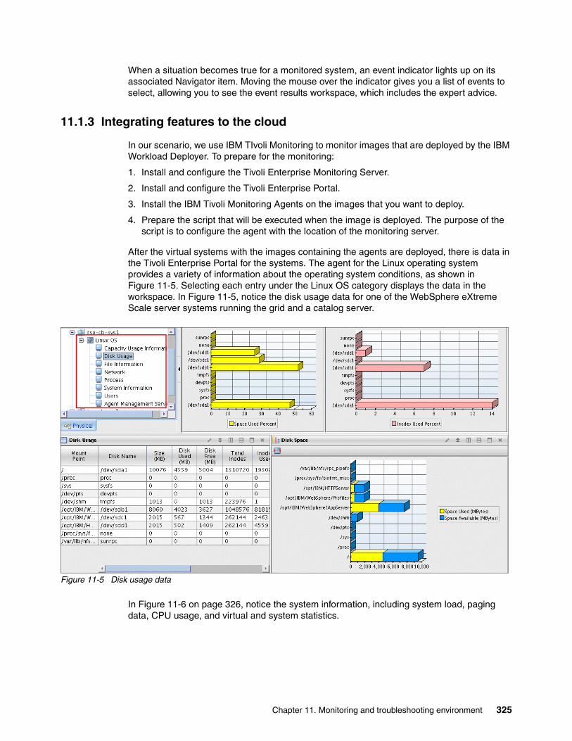
When a situation becomes true for a monitored system, an event indicator lights up on its associated Navigator item. Moving the mouse over the indicator gives you a list of events to select, allowing you to see the event results workspace, which includes the expert advice.
11.1.3 Integrating features to the cloud
In our scenario, we use IBM TIvoli Monitoring to monitor images that are deployed by the IBM Workload Deployer. To prepare for the monitoring:
1. Install and configure the Tivoli Enterprise Monitoring Server.
2. Install and configure the Tivoli Enterprise Portal.
3. Install the IBM Tivoli Monitoring Agents on the images that you want to deploy.
4. Prepare the script that will be executed when the image is deployed. The purpose of the script is to configure the agent with the location of the monitoring server.
After the virtual systems with the images containing the agents are deployed, there is data in the Tivoli Enterprise Portal for the systems. The agent for the Linux operating system provides a variety of information about the operating system conditions, as shown in Figure 11-5. Selecting each entry under the Linux OS category displays the data in the workspace. In Figure 11-5, notice the disk usage data for one of the WebSphere eXtreme Scale server systems running the grid and a catalog server.
Figure 11-5 Disk usage data
In Figure 11-6 on page 326, notice the system information, including system load, paging data, CPU usage, and virtual and system statistics.
Chapter 11. Monitoring and troubleshooting environment 325

Figure 11-6 System data
11.2 Simple Network Management Protocol monitoring
Many organizations have a monitoring system that provides data about the ongoing operation of the infrastructure components. These systems often make use of protocols that are industry standards and have a high degree of reliability. The Simple Network Management Protocol (SNMP) is one of those standards and is embedded in many components both at a hardware and software level. It is contained within the suite of official Internet protocols and consists of standards for network management. The SNMP does not prescribe the set of data or information that a component provides. Instead, it consists of a standard framework that can be extended to provide the types of data desired by the provider.
IBM Workload Deployer incorporates the SNMP within its monitoring subsystem. This allows administrators to receive and respond to alerts quickly and to avoid unanticipated or unnecessary downtime.
The IBM Workload Deployer user interface provides the options to configure the SNMP agent in your appliance so that it can be monitored using an SNMP client. The SNMP clients can poll the SNMP agent in the appliance.
To enable SNMP navigate to the Appliance Monitoring menu option. There are several options in the monitoring menu, as shown in Figure 11-7 on page 327.
326 Virtualization with IBM Workload Deployer: Designing and Deploying Virtual Systems

Figure 11-7 IBM Workload Deployer SNMP configuration options
These options provide configuration settings for the SNMP:
� Enterprise MIBs: This menu option allows the download of the available management information bases (MIBs) for the purpose of importing them into a SNMP client.
� SNMP v2c Communities: Required when monitoring is enabled to authenticate remote access to the SNMP information. The SNMP client passes the agent credentials as a community name to the agent, similar to using a user ID.
Creating a communityTo begin monitoring the IBM Workload Deployer, an SNMP community must first be created.
1. Expand the SNMP v2c Communities option, and click Create community, as shown in Figure 11-8.
Figure 11-8 IBM Workload Deployer create SNMP v2c community
2. Complete the required fields, as shown in Figure 11-9:
– Name: Define the community name. The field supports alphanumeric characters.
– Permissions: Communities are configured as read-only or read-write access and can include a host restriction.
– Host restriction: Entering an IP Address in the Host restriction field limits SNMP communication to only that system. Additional SNMP communities can be added to allow connectivity from other systems. Leaving this field blank permits any system to connect and receive information from the embedded SNMP agent.
Figure 11-9 Adding a SNMP community to IBM Workload Deployer
Chapter 11. Monitoring and troubleshooting environment 327

Click OK to create a new SNMP community. After this step is complete the new community is displayed within the IBM Workload Deployer interface, as shown in Figure 11-10.
Figure 11-10 IBM Workload Deployer with a SNMP community added
Enabling monitoringTo begin monitoring the IBM Workload Deployer select the Enable SNMP on port. A port other than the default port of 161 can be entered if this be required. Figure 11-11 shows the default settings.
Figure 11-11 IBM Workload Deployer SNMP monitoring enabled
The Started message next to the green check mark indicates that the SNMP is enabled and is functioning correctly.
11.3 Troubleshooting procedures
As with any IT solution the hardware and software components can stop functioning as expected. When these conditions occur it is necessary to gather as much information as possible to assist with problem determination and root-cause analysis. IBM Workload Deployer provides a set of troubleshooting functions that enable the examination of fault conditions. It automatically collects much of this data and also provides a mechanism for customizing the granularity of details provided.
The following section covers the following topics and activities:
� An overview of the available troubleshooting options� Accessing and configuring log files and trace levels
Knowing how to perform these activities assists with problem determination and can help to speed issue resolution.
11.3.1 IBM Workload Deployer troubleshooting menu overview
The IBM Workload Deployer provides a menu of options that can be helpful during normal operations and for troubleshooting activities. The menu includes options to view logs, stored configuration objects, physical conditions, such as the temperature of the box, and other useful information. It also includes the options to shut down or restart the appliance:
1. Access the main IBM Workload Deployer page by entering the address of the appliance into the web browser. Log into the IBM Workload Deployer interface as an appliance administrator. For this example the default administrative user cbadmin is used.
328 Virtualization with IBM Workload Deployer: Designing and Deploying Virtual Systems

2. Navigate to the Appliance Troubleshooting menu option, shown in Figure 11-12.
Figure 11-12 IBM Workload Deployer troubleshooting menu option
Figure 11-13 depicts the available options within the troubleshooting menu.
Figure 11-13 IBM Workload Deployer troubleshooting options
These options provide information regarding current operational statuses:
– Logging: Enables access to detailed operational information contained within the kernel, error, storehouse, and trace files. It also allows you to define trace levels.
– Auditing: Provides information regarding the addition, modification, and deletion of auditable objects, such as users, virtual systems, patterns, and other items. This information is retained to ensure that appropriate audit coverage is provided.
– Hardware Capacity: This option details the memory and storage utilization on the IBM Workload Deployer appliance.
– Hardware Temperatures: Provides current operational temperatures of internal components, such as CPU and memory.
– Outbound Connections: Graphical ping interface to ensure that IBM Workload Deployer can communicate with remote systems.
– Power: Enables the restart or complete shutdown of the IBM Workload Deployer.
– Storehouse Browser: Explorer-style window that allows the opening and examination of the configuration files and elements associated with objects, such as clouds, groups, and users.
The following activities demonstrate how to access information from these options within the troubleshooting menu. The Logging option is deliberately omitted from these activities because it is covered in greater depth in 11.3.2, “IBM Workload Deployer log files and trace level configuration” on page 334.
Chapter 11. Monitoring and troubleshooting environment 329

AuditingAuditing data provides information about configuration activities that occurred. To see the audit data, select Appliance Troubleshooting Auditing, as shown in Figure 11-14.
Figure 11-14 IBM Workload Deployer auditing option within the troubleshooting menu
To download all available audit data, click the Download all data link. Clicking this link results in the download of an audit.zip file that contains three files in comma-separated format:
� appliance-audit.csv� license-audit.csv� pvu-audit.csv
These three files contain information about user activity, license activity, and hardware components.
If you are looking for audit data within a specific date range, enter the desired days in the Start date and End date fields, and click Download filtered data. Placing the cursor within the date field causes the interface to display a calendar from which the desired day can be selected. Similarly, a time bar is displayed when placing the cursor within the time field. An optional time zone selection can be made if desired.
The resulting archive contains the same three files as before but is limited to the dates selected. A sample appliance-audit report is provided in Figure 11-15 on page 331, shown as viewed in Microsoft Excel. Some fields (to the right) are not shown in Figure 11-15 on page 331 because of the size of the report.
330 Virtualization with IBM Workload Deployer: Designing and Deploying Virtual Systems
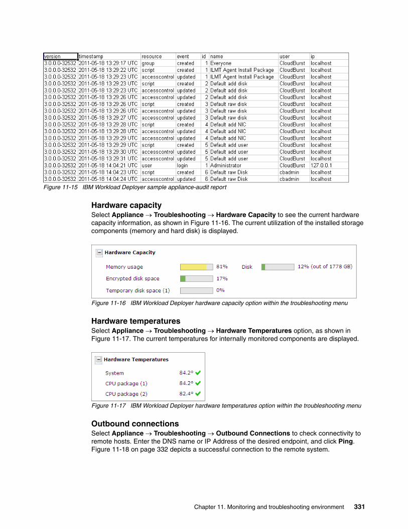
Figure 11-15 IBM Workload Deployer sample appliance-audit report
Hardware capacitySelect Appliance Troubleshooting Hardware Capacity to see the current hardware capacity information, as shown in Figure 11-16. The current utilization of the installed storage components (memory and hard disk) is displayed.
Figure 11-16 IBM Workload Deployer hardware capacity option within the troubleshooting menu
Hardware temperaturesSelect Appliance Troubleshooting Hardware Temperatures option, as shown in Figure 11-17. The current temperatures for internally monitored components are displayed.
Figure 11-17 IBM Workload Deployer hardware temperatures option within the troubleshooting menu
Outbound connectionsSelect Appliance Troubleshooting Outbound Connections to check connectivity to remote hosts. Enter the DNS name or IP Address of the desired endpoint, and click Ping. Figure 11-18 on page 332 depicts a successful connection to the remote system.
Chapter 11. Monitoring and troubleshooting environment 331

Figure 11-18 IBM Workload Deployer successful connection to a remote system
PowerThe IBM Workload Deployer can be shut down or restarted from the console.
Select Appliance Troubleshooting Power, as shown in Figure 11-19.
Figure 11-19 IBM Workload Deployer power option within the troubleshooting menu
The options are to restart the appliance or to shut the appliance down. Selecting either option brings up a second window where you can validate the selection.
Selection of either option results in a second set of options allowing you to wait for active tasks to complete, to perform the shutdown or restart immediately, or to cancel the action, as shown in Figure 11-20. To restart the appliance, select the desired option, and click OK.
Figure 11-20 IBM Workload Deployer restart validation
Storehouse browserThe storehouse browser allows you to view configuration files in raw format versus as displayed on the console pages you use when you configure the appliance and cloud.
Select Appliance Troubleshooting Storehouse Browser, and click the Storehouse Browser link, as shown in Figure 11-21, to open a new window with an Explorer-style interface for the configuration object repository.
Figure 11-21 Selecting the storehouse browser link
The new window has a listing of the configuration objects in the left pane and the configuration details of that object within the right pane, as shown in Figure 11-22 on page 333.
332 Virtualization with IBM Workload Deployer: Designing and Deploying Virtual Systems

Figure 11-22 IBM Workload Deployer storehouse browser configuration object
Clicking Get Contents (New Window) in the pane on the right causes the browser to download the detailed information that is associated with the object. An example of this data is illustrated in Figure 11-23.
Figure 11-23 IBM Workload Deployer storehouse browser configuration object contents
Chapter 11. Monitoring and troubleshooting environment 333

11.3.2 IBM Workload Deployer log files and trace level configuration
IBM Workload Deployer provides a customizable interface for situations that require collection of log files and examination of system messages. These logs can provide significant insight into the operation of the appliance and are a primary means of problem determination should an issue arise. The following procedures demonstrate how to access these log files and adjust the level of detail they contain:
1. Log into the IBM Workload Deployer interface as an appliance administrator. For this example, the default administrative user cbadmin is used. Navigate to the Appliance Troubleshooting menu option. Expand the Logging option, as shown in Figure 11-24.
Figure 11-24 IBM Workload Deployer logging option within the troubleshooting menu
2. After expanding the Logging option, the following links and additional configuration options are displayed:
– Kernel Service log file: Opens a new browser window and presents the messages generated by the kernel service.
– Storehouse log file: Provides information related to the operation of the object configuration repository including any error messages.
– View current error file: Displays the IBM Workload Deployer error log in real time.
– View current trace file: Displays the IBM Workload Deployer trace log in real time.
– Download log files: Displays the local download of the available log files including archived copies of the trace logs.
– Configure trace levels: Allows the customization of the level of detail provided within the trace files.
Kernel Service log fileWhen you select the Kernel Service log file link a new window opens that displays the kernel service log file, as shown in Figure 11-25 on page 335.
334 Virtualization with IBM Workload Deployer: Designing and Deploying Virtual Systems

Figure 11-25 Kernel service log viewer
At the top left of the browser window the Auto-refresh option is set to On. Scrolling to the top of the page causes this option to automatically be set to Off. Scrolling to the bottom of the page causes the option to automatically switch to On. When the refresh option is on, the log updates in real-time to display the most recent messages.
At the bottom left of the browser window are tabs that allow the display of the current log file and any trace files that are associated with the kernel service log. Clicking the console.log.0: More information link causes the entire log to be opened in a new browser window. Each of the tabs have a corresponding link that opens a new browser window and displays the entire log associated with the tab selected.
Storehouse log fileSelect the Logging Storehouse log file to open a new window that displays the storehouse log file, as shown in Figure 11-26 on page 336.
Chapter 11. Monitoring and troubleshooting environment 335

Figure 11-26 Storehouse log viewer
At the top left of the browser window the Auto-refresh option is set to On. Scrolling to the top of the page causes this option to automatically be set to Off. When set to On, the log updates in real-time to display the most recent messages.
At the bottom left of the browser window are tabs that allow the display of the current log file and any trace files that are associated with the storehouse log. Clicking the console.log.0: More information link causes the entire log to be opened within a new browser window. Each of the tabs has a corresponding link that opens a new browser window and displays the entire log that is associated with the selected tab.
View current error fileIn the Logging menu, select the View current error file link to open a new browser window that displays the real-time messages associated with the error file, as shown in Figure 11-27 on page 337.
336 Virtualization with IBM Workload Deployer: Designing and Deploying Virtual Systems

Figure 11-27 Error log
At the top of the browser window are Clear and Pause links. Clicking the Clear link causes the browser window to be cleared and only new messages from that point on are displayed. Clicking the Pause link causes the automatic display of new messages to cease and the link changes to Restart. By clicking the Restart link normal operation is resumed and new messages are displayed immediately.
View current trace fileIn the Logging menu, select the View current trace file link to open a new window with the trace file displayed in current time, as shown in Figure 11-28.
Figure 11-28 Current trace file
At the top of the browser window are Clear and Pause links. Clicking the Clear link causes the browser window to be cleared and only new messages from that point on are displayed. Clicking the Pause link causes the automatic display of new messages to cease and the link changes to Restart. Clicking the Restart link causes the normal display to resume, and new messages are displayed immediately.
Downloading log filesIn the Logging menu, select the Download log files link to cause an archive file named trace.zip to be downloaded locally.
Chapter 11. Monitoring and troubleshooting environment 337

Configuring trace levels and adding a custom trace stringCustomizing the trace levels allows you to define the level of trace data to collect to assist with problem determination and resolution. Trace strings can be added and removed as needed to support operational requirements:
1. In the Logging menu, expand the Configure trace levels option, as shown in Figure 11-29. After expanding this option, the available trace strings and their associated trace level is displayed.
Figure 11-29 IBM Workload Deployer configure trace levels expanded
2. To modify the trace level associated with a trace string, click the link to the right of the trace string, as shown in Figure 11-30, and select the desired level from the drop-down list that appears.
Figure 11-30 IBM Workload Deployer modify trace level link
After changing the trace level to the desired setting, click Save.
3. To add a new trace string, click Add trace level, as shown in Figure 11-31 on page 339 at the bottom of the trace level list, and enter the desired information.
Important: The trace.zip archive contains all of the logs necessary for IBM to perform an initial problem assessment. Download it immediately upon recognition of abnormal operations of IBM Workload Deployer and attach it to the Problem Management Resolution (PMR).
338 Virtualization with IBM Workload Deployer: Designing and Deploying Virtual Systems

Figure 11-31 IBM Workload Deployer add new trace setting
After adding the new trace string, it is placed into the trace level list in alphabetical order and the associated trace level can now be modified as described in the previous step.
4. To delete the new trace string and its associated level, click the red X next to the trace level, as shown in Figure 11-32. The trace string is immediately removed from the list.
Figure 11-32 IBM Workload Deployer removing the com.itso.apc trace setting
Chapter 11. Monitoring and troubleshooting environment 339

340 Virtualization with IBM Workload Deployer: Designing and Deploying Virtual Systems

Related publications
The publications listed in this section are considered particularly suitable for a more detailed discussion of the topics covered in this book.
IBM Redbooks
The following IBM Redbooks publications provide additional information about the topic in this document. Note that some publications referenced in this list might be available in softcopy only.
� WebSphere Cloudburst Appliance and PowerVM, SG24-7806
� Adopting Cloud Computing using the WebSphere CloudBurst Appliance, REDP-4708
� Rapid WebSphere Application Server Provisioning with WebSphere CloudBurst Appliance, REDP-4565
You can search for, view, download, or order these documents and other Redbooks, Redpapers, Web Docs, draft, and additional materials, at the following web site:
ibm.com/redbooks
Online resources
These websites are also relevant as further information sources:
� Application environment migration with WebSphere CloudBurst
http://www.ibm.com/developerworks/cloud/tutorials/cl-appmigration/index.html
� Automated WebSphere Environment Management with RAFW
http://www.websphereusergroup.org.uk/wug/files/presentations/30/David_Sayers_&_Leigh_Williamson_-_RAFW_for_UK_WUG_2010_Sept_v2.pdf
� Build a private cloud with CloudBurst and TSAM
http://www.ibm.com/developerworks/cloud/library/cl-cloudbursttsam/
� Cloud computing for the enterprise, Part 3: Using WebSphere CloudBurst to create private clouds
http://www.ibm.com/developerworks/websphere/techjournal/0906_amrhein/0906_amrhein.html
� Collect troubleshooting data: MustGather for the IBM WebSphere CloudBurst Appliance
http://www-01.ibm.com/support/docview.wss?rs=4007&uid=swg21391319
� Customizing with WebSphere CloudBurst, Part 1: Creating highly customized private clouds
http://www.ibm.com/developerworks/websphere/techjournal/0907_amrhein/0907_amrhein.html
© Copyright IBM Corp. 2011. All rights reserved. 341

� Enabling Clouds with WebSphere
http://docs.google.com/viewer?a=v&pid=sites&srcid=ZGVmYXVsdGRvbWFpbnxzbmVoYWxhbnRhbml8Z3g6NjliYWMxN2RlNTIyOThkYg
� IBM Deployment Planning and Automation
http://www.websphereusergroup.org.uk/wug/files/presentations/31/Leigh_Williamson_Dave_Sayers_-_Rational_Deployment_-_UK_WUG_March_2011.pdf
� IBM Private Cloud Strategy, Snehal Antani
http://docs.google.com/viewer?a=v&pid=sites&srcid=ZGVmYXVsdGRvbWFpbnxzbmVoYWxhbnRhbml8Z3g6M2JhOTliYTRkNDZhMDAzYQ
� IBM Workload Deployer Information Center
http://publib.boulder.ibm.com/infocenter/worlodep/v3r0m0/index.jsp
� IBM WebSphere CloudBurst Appliance Information Center
http://publib.boulder.ibm.com/infocenter/wscloudb/v2r0/index.jsp
� Know your WebSphere Application Server options for a large cache implementation
http://www.ibm.com/developerworks/websphere/techjournal/0801_alcott/0801_alcott.html
� Managing your private cloud, Part 2: Using the WebSphere CloudBurst REST API interface
http://www.ibm.com/developerworks/websphere/techjournal/0911_amrhein/0911_amrhein.html
� Rational Automation Framework for WebSphere (RAFW), An Overview
http://www.websphereusergroup.org/ibmrafw/blog/download_file.one?id=18409
� Rational Automation Framework for WebSphere (RAFW), An Overview
http://www.websphereusergroup.org/ibmrafw/blog/download_file.one?id=18409
� Simplifying WebSphere Development: Using WebSphere CloudBurst and Rational Automation Framework for WebSphere
http://www.websphereusergroup.org/dustinamrhein/blog/download_file.one?id=21201
� Simplifying WebSphere Development: Using WebSphere CloudBurst and Rational Automation Framework for WebSphere
http://www.websphereusergroup.org/dustinamrhein/blog/download_file.one?id=21201
� WebSphere CloudBurst plus Rational Automation Framework for WebSphere
http://www.ibm.com/developerworks/cloud/library/cl-hardinfra/index.html
� WebSphere CloudBurst plus Rational Automation Framework for WebSphere
http://www.ibm.com/developerworks/cloud/library/cl-hardinfra/index.html
� What’s New in IBM Rational Software Architect
ftp://ftp.software.ibm.com/software/emea/de/rsc/tag1/WED_PM_WAS_1_1_Leroux_IBM.pdf
� What you want to know about HTTP session persistence
http://www.ibm.com/developerworks/websphere/techjournal/0809_col_burckart/0809_col_burckart.html
342 Virtualization with IBM Workload Deployer: Designing and Deploying Virtual Systems

� HTTP session management, WebSphere eXtreme Scale Information Center
http://publib.boulder.ibm.com/infocenter/wxsinfo/v7r1/index.jsp?topic=/com.ibm.websphere.extremescale.over.doc/cxshttpsession.html
� IBM WebSphere Developer Technical Journal: The Ideal WebSphere Development Environment, Keys Botzum and Wayne Beaton
http://www.ibm.com/developerworks/websphere/techjournal/0312_beaton/beaton.html
� The "special sauce" inside the WebSphere CloudBurst Appliance
http://www.ibm.com/developerworks/websphere/techjournal/0909_col_willenborg/0909_col_willenborg.html
� Using virtual image templates to deploy WebSphere Application Server, Ruth Willenborg, Qingbo Wang, David Gilgen, Shawn Smith, Le He
http://www.ibm.com/developerworks/websphere/techjournal/0705_willenborg/0705_willenborg.html
� Rational Automation Framework for WebSphere (RAFW), An Overview
http://www.websphereusergroup.org/ibmrafw/blog/download_file.one?id=18409
� Simplifying WebSphere Development: Using WebSphere CloudBurst and Rational Automation Framework for WebSphere
http://www.websphereusergroup.org/dustinamrhein/blog/download_file.one?id=21201
� Automated WebSphere Environment Management with RAFW
http://www.websphereusergroup.org.uk/wug/files/presentations/30/David_Sayers_&_Leigh_Williamson_-_RAFW_for_UK_WUG_2010_Sept_v2.pdf
� WebSphere CloudBurst plus Rational Automation Framework for WebSphere
http://www.ibm.com/developerworks/cloud/library/cl-hardinfra/index.html
Help from IBM
IBM Support and downloads
ibm.com/support
IBM Global Services
ibm.com/services
Related publications 343

344 Virtualization with IBM Workload Deployer: Designing and Deploying Virtual Systems

(0.5” spine)0.475”<
->0.873”
250 <->
459 pages
Virtualization with IBM
Workload Deployer: Designing and Deploying Virtual System
s
Virtualization with IBM
Workload
Deployer: Designing and Deploying
Virtualization with IBM
Workload
Deployer: Designing and Deploying Virtual System
s
Virtualization with IBM
Workload Deployer: Designing and Deploying Virtual

Virtualization with IBM
Workload
Deployer: Designing and Deploying Virtual System
s
Virtualization with IBM
Workload
Deployer: Designing and Deploying Virtual System
s


®
SG24-7967-00 ISBN 0738436003
INTERNATIONAL TECHNICALSUPPORTORGANIZATION
BUILDING TECHNICAL INFORMATION BASED ON PRACTICAL EXPERIENCE
IBM Redbooks are developed by the IBM International Technical Support Organization. Experts from IBM, Customers and Partners from around the world create timely technical information based on realistic scenarios. Specific recommendations are provided to help you implement IT solutions more effectively in your environment.
For more information:ibm.com/redbooks
®
Virtualization with IBM Workload DeployerDesigning and Deploying Virtual Systems
Deploy highly customized virtual systems to a private cloud
Use Rational Automation Framework for WebSphere for customization
Discover tools that complement the IBM Workload Deployer
The IBM Workload Deployer appliance provides a solid foundation for private cloud strategy, enabling the rapid adoption and deployment of both infrastructure and platform as a Service offering. The IBM Workload Deployer uses the concept of patterns to describe the logical configuration of both the physical and virtual assets that comprise a particular solution. The use of patterns allows an organization to construct an individual element or integrated solution one time, and then dispense the final product on demand. Virtual system patterns are comprised of an operating system and IBM software solutions, such as WebSphere Application Server and WebSphere Virtual Enterprise. Virtual application patterns are constructed to support a single application workload.
This book focuses on the virtual systems capability of the IBM Workload Deployer and specifically addresses the process of building customized virtual systems that go beyond the standard capabilities of the virtual images available with the product.
The book starts by describing private clouds and how they can benefit your business. It introduces the IBM Workload Deployer and its capabilities, and then talks about the various tools that you can use to enhance the process of planning, customizing, and automating virtual system deployment. A sample is used to illustrate how the standard virtual images that are available for the IBM Workload Deployer can be customized for a robust solution that includes dynamic workload management, high-performing data caching, and monitoring of system state. The book then discusses how you can use the IBM Workload Deployer to facilitate the progression of an application through its lifecycle. Finally, an overview is provided of the troubleshooting capabilities that come with the IBM Workload Deployer.
Back cover