Embed Size (px)
Citation preview

STATE OF CALIFORNIA-BUSINESS TRANSPORTATION AND HOUSING AGENCY GRAY DAVIS Governor
DEPARTMENT OF TRANSPORTATION ESCOE MS 43 1727 30TH Street 2ND Floor Sacramento CA 95816
October 20 2000
04-CCSol-80-1952270007 04-013054
Addendum No 2
Dear Contractor
This addendum is being issued to the contract for construction on State highway in CONTRA COSTA AND SOLANO COUNTIES IN CROCKETT AND VALLEJO FROM OLEUM REFINERY ROAD UNDERCROSSING TO CARQUINEZ BRIDGE TOLL PLAZA
Submit bids for this work with the understanding and full consideration of this addendum The revisions declared in this addendum are an essential part of the contract
Bids for this work will be opened on November 15 2000 instead of the original date of November 1 2000
This addendum is being issued to set a new bid opening date as shown herein and revise the Project Plans the Notice to Contractors and Special Provisions and the Proposal and Contract
Project Plan Sheets 1 3 4 5 6 7 8 9 10 11 17 20 21 22 37 40 74 79 83 84 85 86 89 93 100 102C 103 106 113A 114 115 116 117 119 120 121 129 130 131 132 136 137 138 139 140 141 142 143 159 180 184 197 203 205 206 207 208 209 210 211 226 227 228 230 238 273 339 347 388 390 402 654 655 656 688 690 822 824 833 911 955 957 973 1027 1028 1043 and 1047 are revised A half-sized copy of the revised sheets are attached for substitution for the like-numbered sheets
Project Plan Sheets 72A 87A 96A 102A 102B 158A 163A 924A and 924B are added A half-sized copy of the added sheets are attached for addition to the project plans
Project Plan Sheets 30 53 76 102 151 152 and 153 are deleted
In the Notice to Contractors and Special Provisions the A + B BIDDING SPECIAL NOTICE is revised as attached
In the Special Provisions Section 3 AWARD AND EXECUTION OF CONTRACT is revised as attached
In the Special Provisions Section 4 BEGINNING OF WORK TIME OF COMPLETION AND LIQUIDATED DAMAGES is revised as attached
In the Special Provisions Section 5-130 AVAILABLE EXISTING DOCUMENTS the first paragraph is revised as follows
The following items are available for inspection at Department of Transportation at 111 Grand Avenue Oakland California 94612
As-Builts for the 1958 Bridge As-Builts for the 1927 Bridge Foundation Recommendation for the New Crockett Interchange Retaining Walls R1 and
R2 Foundation Recommendation Westbound On-Ramp Wall R3 Foundation Recommendation Vista Del Rio Wall 4
Addendum No 2 Page 2 October 20 2000
04-CCSol-80-1952270007 04-013054
Supplemental Foundation Recommendations for the Crockett Interchange (West of Existing Bridge)
Foundation Recommendations for Crockett Interchange Viaduct Westbound On-Ramp Westbound Off-Ramp and Eastbound Off-Ramp
South Anchorage Pile Field Acceptance Criteria Pile Dynamic Analysis and Pile Load Test Results
Bent 7 Pile Field Acceptance Criteria Pile Dynamic Analysis and Pile Load Test Results
Crockett Viaduct Driveability Analysis Westbound Off-Ramp Driveability Analysis Contract Plans and Specifications for the New Carquinez Bridge Project
(EA 04-013014) Foundation Report for the New Carqinez Bridge Project (EA 04-013014)
In the Special Provisions Section 10-105 TEMPORARY CREEK DIVERSION SYSTEM is deleted
In the Special Provisions Section 10-113 TEMPORARY FENCE (TYPE ESA) is deleted
In the Special Provisions Section 10-118 PROGRESS SCHEDULE (CRITICAL PATH) the third paragraph is revised as follows
PRECONSTRUCTION SCHEDULING CONFERENCE The Engineer shall schedule and conduct a Preconstruction Scheduling Conference with the
Contractors Project Manager and Construction Scheduler within seven days after the bidder has received the contract for execution At this meeting the requirements of this section of the special provisions will be reviewed with the Contractor The Contractor shall be prepared to discuss its schedule methodology proposed sequence of operations the activity identification system for labeling all work activities the schedule file numbering system and any deviations it proposes to make from the Stage Construction Plans
In the Special Provisions Section 10-118 PROGRESS SCHEDULE (CRITICAL PATH) subsection EQUIPMENT AND SOFTWARE the first paragraph is revised as follows
EQUIPMENT AND SOFTWARE The Contractor shall provide for the States exclusive possession and use a complete computer system
specifically capable of creating storing updating and producing CPM schedules Before delivery and setup of the computer system the Contractor shall submit to the Engineer for approval a detailed list of all computer hardware and software the Contractor proposes to furnish The minimum computer system to be furnished shall include the following
A Complete computer system including keyboard mouse 20 inch color SVGA monitor (1024x768 pixels) Intel Pentium III 850 MHz microprocessor chip or equivalent
B Computer operating system software compatible with the selected processing unit for Windows 95 or later or equivalent
C Minimum one-twenty-eight (128) megabytes of random access memory (RAM) D A 64 gigabytes minimum hard disk drive a 144 megabyte 3 12 inch floppy disk
drive 32x speed minimum CD-ROM drive Ethernet card and 56k modem
Addendum No 2 Page 3 October 20 2000
04-CCSol-80-1952270007 04-013054
E A color-ink-jet plotter with a minimum 36 megabyte RAM capable of 300 dots per inch color 600 dots per inch monochrome or equivalent capable of printing fully legible time scaled charts and network diagrams in four colors with a minimum size of 36 inches by 48 inches (E size) and is compatible with the selected system an HP Design Jet 1055 CM or equivalent plotter stand roll paper assembly and automatic paper cutter and provide plotter paper and ink cartridges throughout the contract
F CPM software shall be Primavera Project Planner the latest version for Windows 95 or later
G Scheduler Analyzer Pro or equivalent (a suite of programs to assist in schedule analysis) in the latest version for Windows 95 Windows NT or later and
H Microsoft Office Software the latest version for Windows 95 Windows NT or later and McAfee Virus software or equivalent
In the Special Provisions Section 10-119 OVERHEAD is revised as attached
In the Special Provisions Section 10-121 OBSTRUCTIONS is revised as attached
In the Special Provisions Section 10-129 PORTABLE CHANGEABLE MESSAGE SIGN the second paragraph is revised as follows
Portable changeable message signs shall be on the project at all times and available for public awareness information purposes as directed by the Engineer
In the Special Provisions Section 10-135 RAISE BRIDGE subsection REMOVE CONCRETE is revised to Section 10-136 REMOVE CONCRETE
In the Special Provisions Section 136 REMOVE CONCRETE the first paragraph is revised as follows
Concrete where shown on the plans to be removed shall be removed and shall conform to the provisions in Section 15 Existing Highway Facilities of the Standard Specifications and these special provisions
In the Special Provisions Section 10-138 EARTHWORK the following paragraph is added after the fourth paragraph
Full compensation for shoring as required at Retaining Wall R-1 shall be considered as included in the contract price paid per cubic meter for roadway excavation and no separate paymentadditional compensation will be madeallowed therefor
In the Special Provisions Section 10-155 PILING subsection CAST-IN-DRILLED-HOLE CONCRETE PILES is revised as attached
In the Special Provisions Section 10-155 PILING subsection SLURRY is revised as attached
In the Special Provisions Section 10-156 STEEL SOLDIER PILING subsection MEASUREMENT AND PAYMENT (PILING) the following paragraph is added after the eighth paragraph
Excavation of open ended steel shells beyond the limits shown on the plans shall be backfilled with concrete fill Full compensation for backfilling the open ended steel shells with concrete fill beyond the limits shown on the plans shall be considered as included in the contract unit price paid for drive pile and no additional compensation will be allowed therefor
Addendum No 2 Page 4 October 20 2000
04-CCSol-80-1952270007 04-013054
In the Special Provisions Section 10-156 STEEL SOLDIER PILING the section heading Section 10-156 STEEL SOLDIER PILING is revised to subsection heading STEELSOLDIER PILING
In the Special Provisions Section 10-160 CONCRETE STRUCTURES subsections TEMPORARY HINGE TIEDOWNS DRILL AND BOND DOWEL (EPOXY CARTRIDGE) and MEASUREMENT AND PAYMENT are added as attached after subsection ELASTOMERIC BEARING PADS
In the Special Provisions Section 10-164 ARCHITECTURAL SURFACE (TEXTURED CONCRETE) is revised as attached
In the Special Provisions Section 10-175 ISOLATION CASINGS is revised as attached
In the Special Provisions Section 10-198 BRIDGE DECK DRAINAGE SYSTEM the following paragraph is added after the second paragraph
Stainless steel plate shall conform to the requirements in ASTM Designation A 276 Type 316
In the Special Provisions Section 10-172 WELDED HEADED BAR REINFORCEMENT the section heading Section 10-172 WELDED HEADED BAR REINFORCEMENT is revised to subsection heading WELDED HEADED BAR REINFORCEMENT
In the Special Provisions Section 10-1108 SURVEY OF EXISTING NON-HIGHWAY FACILITIES is added as attached
In the Special Provisions Section 10-204 HIGHWAY PLANTING subsection PLANT ESTABLISHMENT WORK the first paragraph is revised as follows
PLANT ESTABLISHMENT WORK The plant establishment period shall be Type 2 and shall be not less than 1100 working days
In the Special Provisions Section 10-601 AIR AND WATER LINES is added as attached
In the Special Provisions Section 10-602 MODIFY BRIDGE WATER LINE is added as attached
In the Proposal and Contract the Engineerrsquos Estimate Items 8 10 20 21 23 24 30 40 41 58 68 69 79 82 102 103 107 108 125 126 127 128 142 151 152 182 184 187 189 190 194 198 199 200 201 202 204 208 214 228 231 232 233 236 258 and 259 are revised Items 261 262 263 264 and 265 are added and Items 1 13 143 and 260 are deleted as attached
To Proposal and Contract book holders
Replace the entire Engineers Estimate in the Proposal with the attached revised Engineers Estimate The revised Engineers Estimate is to be used in the bid
Attached is a copy of the Material Information California Department of Fish and Game Permit Indicate receipt of this addendum by filling in the number of this addendum in the space provided on the
signature page of the proposal Submit bids in the Proposal and Contract book you now possess Holders who have already mailed their
book will be contacted to arrange for the return of their book Inform subcontractors and suppliers as necessary
Addendum No 2 Page 5 October 20 2000
04-CCSol-80-1952270007 04-013054
This office is sending this addendum by UPS overnight mail to Proposal and Contract book holders to ensure that each receives it
If you are not a Proposal and Contract book holder but request a book to bid on this project you must comply with the requirements of this letter before submitting your bid
Sincerely
ORIGINAL SIGNED BY
NICK YAMBAO Chief Office of Plans Specifications amp Estimates Division of Office Engineer
Attachments
A + B BIDDING SPECIAL NOTICE
The bidders attention is directed to Section 2 Proposal Requirements and Conditions Section 3-101B Award and Execution of Contract and Section 4 Beginning of Work Time of Completion and Liquidated Damages in the special provisions In addition to the item prices and totals the proposal shall set forth the number of working days bid to complete all the Phase II work (except plant establishment work) Working days are defined in Section 4 All bids will be compared on the basis of the sum of the Engineers Estimate of the quantities of work to be done (TOTAL BID (A)) plus the product of the number of working days bid to complete all the Phase II (except plant establishment work) work and the cost per day shown on the Engineers Estimate (TOTAL BID (B)) The lowest bid will be determined on the basis of the Total Basis for Comparison of Bids set forth in the Engineers Estimate
Bids in which the number of working days bid exceed 610 for all the Phase II (except plant establishment work) work will be considered non-responsive and will be rejected
The bidders attention is also directed to the provisions in Section 4 of the special provisions regarding liquidated damages The total number of working days to complete all work in the contract shall be the number of working days bid plus 800 days excluding working days when only plant establishment is to be performed
No incentive payments will be paid nor will disincentive deductions be charged on this project For purposes of determining liquidated damages all work must be completed for a given Phase and the contract
accepted by the Director as specified in Section 7-117 Acceptance of Contract of the Standard Specifications Examples of determining liquidated damages for Phase I work are as follows
Completing all the work in Phase I at 1155 pm on day 800 shall be deemed completing all the work in Phase I shown on the project plans on day 800
Completing all the work in Phase I at 1205 am on day 801 shall be deemed completing all the work in Phase I shown on the project plans on day 801
Examples of determining liquidated damages for Phase I working days and Phase II work bid (except plant establishment work) are as follows
Contractor bids 600 working days for Phase II work (except plant establishment work) The contractor has been notified that the New Carquinez Bridge (contract 04-013014) is ready to accept traffic on day 790 The contractor has 1400 (800 plus 600) working days to completely finish Phase II work (except plant establishment work)
Contractor bids 600 working days for Phase II work (except plant establishment work) The contractor completely finishes all the work in Phase I on day 800 The contractor has been notified that the New Carquinez Bridge (contract 04-013014) is ready to accept traffic on day 805 The contractor has 1405 (805 plus 600) working days to completely finish Phase II work (except plant establishment work)
Contractor bids 600 working days for Phase II work (except plant establishment work) The contractor completely finishes all the work in Phase I on day 830 The contractor has been notified that the New Carquinez Bridge (contract 04-013014) is ready to accept traffic on day 800 The contractor has 1400 (800 plus 600) working days to completely finish Phase II work (except plant establishment work)
CONTRACT NO 04-013054 REVISED PER ADDENDUM NO 2 DATED OCTOBER 20 2000
SECTION 3 AWARD AND EXECUTION OF CONTRACT
The bidders attention is directed to the provisions in Section 3 Award and Execution of Contract of the Standard Specifications and these special provisions for the requirements and conditions concerning award and execution of contract
The award of contract if it be awarded will be to the lowest responsible bidder whose proposal complies with all the requirements prescribed and who has met the goal for DVBE participation or has demonstrated to the satisfaction of the Department adequate good faith efforts to do so Meeting the goal for DVBE participation or demonstrating to the satisfaction of the Department adequate good faith efforts to do so is a condition for being eligible for award of contract
It is anticipated that this contract will be awarded within 10 days after the bid opening The contract shall be signed by the successful bidder and shall be received with contract bonds by the Department within
4 days including Saturdays Sundays and legal holidays after the bidder has received notice that the contract has been awarded Failure to do so shall be just cause for forfeiture of the proposal guaranty The executed contract documents shall be delivered to the following address Department of Transportation PO Box 942874 Sacramento CA 94274-0001 Attn Office Engineer (MS 43)- Contracts
Within 2 days not including Saturdays Sundays and legal holidays of return of the executed contract and bonds the Department will notify the successful bidder of either approval of the contract by the Attorney General or the attorney appointed and authorized to represent the Department of Transportation or disapproval of the submittal Should the Department fail to provide notification within said 2 days the delay will be considered a right of way delay as specified in Section 8-109 Right of Way Delays of the Standard Specifications
The bidder shall bid the number of working days for it to complete the work in Phase II (except plant establishment work) of this contract Bids in which the number of working days bid for completion of all the work in Phase II exceed 610 days will be considered non-responsive and will be rejected
All bids will be compared on the basis of the Engineers Estimate of the quantities of work to be done (TOTAL BID (A)) plus the product of the number of working days bid for completion of all the work in Phase II and the cost per day shown on the Engineers Estimate (TOTAL BID (B))
The apparent lowest bid will be determined on the basis of the Total Basis for Comparison of Bids (A + B) set forth in the Engineers Estimate The contract price for the awarded contract will be the TOTAL BID (A) set forth in the proposal
Each of the two bonds specified in Section 3-102 Contract Bonds of the Standard Specifications shall be the sum equal to 100 percent of the Total Bid (A) set forth on the proposal form
A Payee Data Record form will be included in the contract documents to be executed by the successful bidder The purpose of the form is to facilitate the collection of taxpayer identification data The form shall be completed and returned to the Department by the successful bidder with the executed contract and contract bonds For the purposes of the form vendor shall be deemed to mean the successful bidder The form is not to be completed for subcontractors or suppliers Failure to complete and return the Payee Data Record form to the Department as provided herein will result in the retention of 20 percent of payments due the contractor and penalties of up to $20000 This retention of payments for failure to complete the Payee Data Record form is in addition to any other retention of payments due the Contractor
It is expected that within 2 days not including Saturdays Sundays and legal holidays of return of the executed contract and bonds the Department will notify the successful bidder of either approval of the contract by the Attorney General or the attorney appointed and authorized to represent the Department of Transportation or disapproval of the submittal
Attention is also directed to Small Business Preference of these special provisions Any bidder who is certified as a Small Business by the Department of General Services Office of Small Business Certification and Resources will be allowed a preference in the award of this contract if it be awarded under the following conditions
A The apparent low bidder is not certified as a Small Business or has not filled out and signed the Request for Small Business Preference included with the bid documents and attached a copy of their Office of Small Business Certification and Resources (OSBCR) small business certification letter to the form and
B The bidder filled out and signed the Request for Small Business Preference form included with the bid documents and attached a copy of their Office of Small Business Certification and Resources (OSBCR) small business certification letter to the form
CONTRACT NO 04-013054 REVISED PER ADDENDUM NO 2 DATED OCTOBER 20 2000
The small business preference will be a reduction in the bid submitted by the small business contractor for bid comparison purposes by an amount equal to 5 percent of the amount bid by the apparent low bidder the amount not to exceed $50000 If this reduction results in the small business contractor becoming the low bidder then the contract will be awarded to the small business contractor on the basis of the actual bid of the small business contractor notwithstanding the reduced bid price used for bid comparison purposes
Attention is also directed to California Company Preference of these special provisions The amount of the California company reciprocal preference shall be equal to the amount of the preference applied by
the state of the nonresident contractor with the lowest responsive bid except where the California company is eligible for a California Small Business Preference in which case the preference applied shall be the greater of the two but not both
If the bidder submitting the lowest responsive bid is not a California company and with the benefit of the reciprocal preference a California companys responsive bid is equal to or less than the original lowest responsive bid the California company will be awarded the contract at its submitted bid price except as provided below
Small business bidders shall have precedence over nonsmall business bidders in that the application of the California company preference for which nonsmall business bidders may be eligible shall not result in the denial of the award to a small business bidder
CONTRACT NO 04-013054 REVISED PER ADDENDUM NO 2 DATED OCTOBER 20 2000
SECTION 4 BEGINNING OF WORK TIME OF COMPLETION AND LIQUIDATED DAMAGES
Attention is directed to the provisions in Section 8-103 Beginning of Work in Section 8-106 Time of Completion and in Section 8-107 Liquidated Damages of the Standard Specifications and these special provisions
The 72 hours advance notice before beginning work as referred to in Section 8-103 Beginning of Workrdquo is changed to 24 hours advance notice for this project
A working day as defined in Section 8-106 ldquoTime of Completionrdquo is re-defined for this project with the following exceptions
Subparagraph (a) shall not apply Saturdays Sundays and legal holidays including days of inclement weather that do not exceed the days described below shall be counted as working days
Subparagraph (b) is re-defined to the following A rainy season is defined as the twelve month period beginning after the contract has been approved by the Attorney General or the attorney appointed and authorized to represent the Department of Transportation For each rainy season of the contract forty-five days (45) of inclement weather are expected The Contractor is expected to anticipate the loss of forty-five days of work to inclement weather in his bid for each rainy season as defined above The forty-five days of inclement weather per rainy season shall be reduced for any partial rainy season on the contract as follows
Partial Year Inclement Weather Days = ((forty-five days12) x (months remaining in raining season))
The contract will be extended an additional working day for each inclement weather day in excess of the days described above The Contractor will not be charged for a working day for days on which the Contractor is prevented by inclement weather or conditions resulting immediately therefrom adverse to the current controlling operation or operations as determined by the Engineer for proceeding with at least 75 percent of the normal labor and equipment force engaged on such operation or operations for at least 60 percent of the total daily time being currently spent on the controlling operation or operations in excess of the days described above
The work shall be completed in two phases Phase I consists of completing work as shown on the contract plan SC-4 (Stage Construction Stage 3 Phase 1) and such other work including the bridge barriers the railing on the westerly barrier all signs lighting and electrical systems traffic operations and call box systems that will allow the New Crockett Viaduct to be completely open to traffic with a minimum of four lanes with final pavement delineation Phase II consists of all remaining work
Phase I work shall be diligently prosecuted to completion before the expiration 800 working days beginning at 1201 am on the day after the day of contract award
The Contractor shall pay to the State of California the sum of $57000 per day for each and every calendar days delay in finishing the work in Phase I excess of 800 working days
Delays due to actions required by the Engineer performing normal inspection testing and review duties shall be considered as included in the number of working days bid for completion of the contract and no extensions of time will be allowed for such actions in determining liquidated damages
The maximum number of days specified for the completion of the Phase I work contemplated herein is considered insufficient to permit completion of the work by the Contractor working a normal number of hours per day or week on a single shift basis Should the Contractor fail to maintain the progress of the work in accordance with the Progress Schedule required in these special provisions additional shifts will be required to the extent deemed necessary be added to ensure that the progress conforms to the above mentioned schedule and that the work will be completed within the number of working days bid
Phase II work (except plant establishment work) shall be diligently prosecuted to completion before the expiration of the number of working days bid beginning at 1201am on the day after the expiration of 800 working days or upon notification of the contractor by the engineer that the New Carquinez Bridge (contract 04-013014) is ready to accept traffic whichever is later Non-conflicting Phase II work may be performed concurrently with Phase I work and until such a time (after the expiration of 800 working days) that the contractor is informed that the New Carquinez Bridge is ready to accept traffic
CONTRACT NO 04-013054 REVISED PER ADDENDUM NO 2 DATED OCTOBER 20 2000
The Contractor shall pay to the State of California the sum of $35000 per day for each and every calendar days delay in finishing Phase II work (except plant establishment work) in excess of the total number of working days bid
Full compensation for any additional costs occasioned by compliance with the provisions in this section shall be considered as included in the prices paid for the various contract items of work and no additional compensation will be allowed therefor
No incentive payments will be paid nor will disincentive deductions be charged on this project The 72 hours advance notice before beginning work as referred to in said Section 8-103 is changed to 24 hours advance
notice for this project The time limit specified for the completion of the work contemplated herein is considered insufficient to permit
completion of the work by the Contractor working a normal number of hours per day or week on a single shift basis Should the Contractor fail to maintain the progress of the work in conformance with the Progress Schedule required in these special provisions additional shifts will be required to the extent necessary to ensure that the progress conforms to the abovementioned schedule and that the work will be completed within the time limit specified
Full compensation for any additional costs occasioned by compliance with the provisions in this section shall be considered as included in the prices paid for the various contract items of work and no additional compensation will be allowed therefor
CONTRACT NO 04-013054 REVISED PER ADDENDUM NO 2 DATED OCTOBER 20 2000
10-119 OVERHEAD
The Contractor will be compensated for overhead in accordance with these special provisions Attention is directed to Force Account Payment and Progress Schedule (Critical Path) of these special provisions Section 9-108 Adjustment of Overhead Costs of the Standard Specifications shall not apply Time related overhead shall consist of those overhead costs including field and home office overhead that are in
proportion to the time required to complete the work Time related overhead costs shall not include costs that are not related to time including but not limited to mobilization licenses permits and any other charges incurred only once during duration of the contract
The contract lump sum price paid for time related overhead shall include full compensation for time related overhead incurred by the Contractor and by any joint venture partner subcontractor supplier or other party associated with the Contractor
The contract lump sum price bid for time related overhead will be adjusted only as a result of suspensions and adjustments of time which revise the current contract completion date and which are also any of the following
A suspensions of work ordered in accordance with Section 8-105 Temporary Suspension of Work of the Standard Specifications except
1 suspensions ordered due to the failure on the part of the Contractor to carry out orders given or to perform any provision of the contract and
2 suspensions ordered due to unsuitable weather conditions
B extensions of time granted by the State in accordance with the provisions of the fifth paragraph of Section 8-107 Liquidated Damages of the Standard Specifications or
C reductions in contract time set forth in approved contract change orders in accordance with Section 4-103 Changes of the Standard Specifications
For each day the number of calendar days to complete the contract (days bid to complete Phase II (except plant establishment work) plus 800 days) in conformance with the provisions in Section 4 Beginning of Work Time of Completion and Liquidated Damages of these special provisions is adjusted due to suspensions or adjustments as specified above the lump sum price for time related overhead will be adjusted by an amount equal to the contract lump sum price bid for time related overhead divided by the number of calendar days to complete the contract The provisions in Sections 4-103B Increased or Decreased Quantities and 4-103C Changes in Character of the Work of the Standard Specifications shall not apply to time related overhead
For the purpose of making partial payments pursuant to Section 9-106 Partial Payments of the Standard Specifications time related overhead to be paid in each monthly estimate will be based on the number of working days that occurred during that monthly estimate period The amount earned per day for time related overhead shall be the lesser of the following amounts
A the contract lump sum price for time related overhead divided by the number of calendar days to complete the contract (days bid to complete Phase II (except plant establishment work) plus 800 days) in conformance with the provisions in Section 4 Beginning Of Work Time Of Completion And Liquidated Damages of these special provisions or
B fifteen percent of the original contract amount divided by the number of calendar days to complete the contract (days bid to complete Phase II (except plant establishment work) plus 800 days) in conformance with the provisions in Section 4 Beginning Of Work Time Of Completion And Liquidated Damages of these special provisions
After acceptance of the contract pursuant to Section 7-117 Acceptance of Contract of the Standard Specifications the amount if any of the contract lump sum price for time related overhead not yet paid will be included for payment in the first estimate made after acceptance of the contract in accordance with Section 9-107 Payment after Acceptance of the Standard Specifications
Full compensation for all overhead costs including overhead costs for increases in the quantity of contract items of work other than time related overhead paid for as specified above and other than overhead costs included in the markups specified in Force Account Payment of these special provisions shall be considered as included in the various items of work and no additional compensation will be allowed therefor
CONTRACT NO 04-013054 REVISED PER ADDENDUM NO 2 DATED OCTOBER 20 2000
10-121 OBSTRUCTIONS
Attention is directed to Section 8-110 Utility and Non-Highway Facilities and Section 15 Existing Highway Facilities of the Standard Specifications and these special provisions
Attention is directed to the existence of certain underground facilities that may require special precautions be taken by the Contractor to protect the health safety and welfare of workers and of the public Facilities requiring special precautions include but are not limited to conductors of petroleum products oxygen chlorine and toxic or flammable gases natural gas in pipelines greater than 150 mm in diameter or pipelines operating at pressures greater than 415 kPa (gage) underground electric supply system conductors or cables with potential to ground of more than 300 V either directly buried or in a duct or conduit which do not have concentric grounded or other effectively grounded metal shields or sheaths
The Contractor shall notify the Engineer and the appropriate regional notification center for operators of subsurface installations at least 2 working days but not more than 14 calendar days prior to performing any excavation or other work close to any underground pipeline conduit duct wire or other structure Regional notification centers include but are not limited to the following
Notification Center Telephone Number Underground Service Alert-Northern California (USA) 1-800-642-2444
1-800-227-2600 Underground Service Alert-Southern California (USA) 1-800-422-4133
1-800-227-2600
It is anticipated that the following utility facilities will be relocated prior to the dates shown
Utility Location Date PG ampE -76 mm Gas Line Vista Del Rio 122200 PG ampE - 51 mm Gas Line Virginia Street 122200
Crockett Volenteer FD Pomona Street Wanda Street 13101 Pac Bell OH Telephone Line Pomona Street 13101
PG ampE - Underground Elect Line Pomona Street 13101 PG ampE - Underground Elect Line Vista Del Rio 13101 Pacific Bell - Fiber Optic Cable Wanda Street 112700
Pacific Bell - Underground Tele Line Vista Del Rio 112700 EBMUD - 635 mm water Line Dowrelio Drive 13101 EBMUD - 203 mm water Line WB Off-Ramp Termini at Pomona St 112700
Crockett-Valona San Dist- 152 mm VCP Virginia Street 13101 Crockett-Valona San Dist- 203 mm VCP Kendall Avenue 13101 Crockett-Valona San Dist- 203 mm VCP Vista Del Rio 13101 Crockett-Valona San Dist- 152 mm VCP Ceres Street 13101 Crockett-Valona San Dist- 203 mm VCP Wanda Street amp Loop 112700 Crockett-Valona San Dist- 152 mm VCP Ceres Street amp Wanda Street 13101 Crockett-Valona San Dist- 203 mm VCP Ceres Street amp Wanda Street 13101
ATampT - OH Cable TV Line Wanda Street amp Vista Del Rio 22801 Contra Costa Co - Siren Pole Wanda Street amp Pomona Street 13101
PGampE OH Elect Line Pomona Street Vista Del Rio Kendall Street Wanda Street
32801
CONTRACT NO 04-013054 REVISED PER ADDENDUM NO 2 DATED OCTOBER 20 2000
Installation or relocation of the following utility facilities will require coordination with the Contractors operations The Contractor shall make the necessary arrangements with the utility company through the Engineer and shall submit a schedule of work verified by a representative of the utility company to the Engineer The schedule of work shall provide not less than the following number of working days as defined in Section 8-106 Time of Completion of the Standard Specifications for the utility company to complete their work
Utility (address) Location Working Days PGampE - OH Elect Line Pomona St Vista Del Rio Kendall Ave
Wanda St amp Dowrelio Dr 120
Pacific Bell - Fiber Optic Cable Existing WB Off-Ramp 180 EBMUD - 406 mm Water Line Vista Del Rio 90 EBMUD - 406 mm Water Line Vista Del Rio Kendall Ave amp Virginia St 90
In the event that the utility facilities mentioned above are not removed or relocated by the date specified and if in the opinion of the Engineer the Contractors operations are delayed or interfered with by reason of the utility facilities not being removed or relocated by the date specified the State will compensate the Contractor for the delays to the extent provided in Section 8-109 Right of Way Delays of the Standard Specifications and not otherwise except as provided in Section 8-110 Utility and Non-Highway Facilities of the Standard Specifications
CONTRACT NO 04-013054 REVISED PER ADDENDUM NO 2 DATED OCTOBER 20 2000
CAST-IN-DRILLED-HOLE CONCRETE PILES
Cast-in-drilled-hole concrete piling shall conform to the provisions in Section 49-4 Cast-In-Place Concrete Piles of the Standard Specifications and these special provisions
Within a support location no pile shall be constructed immediately adjacent to recently constructed piles until the adjacent piles have cured for a minimum of 48 hours
The first and second paragraphs of Section 49-401 Description of the Standard Specifications are amended to read
bull Cast-in-place concrete piles shall consist of one of the following
A Steel shells driven permanently to the required bearing value and penetration and filled with concrete B Steel casings installed permanently to the required penetration and filled with concrete C Drilled holes filled with concrete D Rock sockets filled with concrete
bull The drilling of holes shall conform to the provisions in these specifications Concrete filling for cast-in-place concrete piles is designated by compressive strength and shall have a minimum 28-day compressive strength of 25 MPa At the option of the Contractor the combined aggregate grading for the concrete shall be either the 25-mm maximum grading the 125-mm maximum grading or the 95-mm maximum grading Concrete shall conform to the provisions in Section 90 Portland Cement Concrete and Section 51 Concrete Structures Reinforcement shall conform to the provisions in Section 52 Reinforcement
The fourth paragraph of Section 49-403 Drilled Holes of the Standard Specifications is amended to read
bull After placing reinforcement and prior to placing concrete in the drilled hole if caving occurs or deteriorated foundation material accumulates on the bottom of the hole the bottom of the drilled hole shall be cleaned The Contractor shall verify that the bottom of the drilled hole is clean
The provisions of Welding Quality Control of these special provisions shall not apply to temporary steel casings Cast-in-drilled-hole concrete piles 600 mm in diameter or larger may be constructed by excavation and depositing
concrete under slurry
Materials Concrete deposited under slurry shall have a nominal penetration equal to or greater than 90 mm Concrete shall be
proportioned to prevent excessive bleed water and segregation Concrete deposited under slurry shall contain not less than 400 kg of cement per cubic meter For cast-in-drilled-hole concrete piling the following gradation is added to the table in the third paragraph in Section
90-301 General of the Standard Specifications
Primary Aggregate Nominal Size Sieve Sizes Limits of Proposed Gradation 125 mm x 475 mm 95 mm 40 - 78 95 mm x 236 mm 95 mm 50 - 85
At the Contractorrsquos option the Contractor may use either the 125-mm maximum combined aggregate grading or the 95-mm maximum combined aggregate grading For cast-in-drilled-hole concrete piling the following table is added to the first paragraph in Section 90-302 Coarse Aggregate Grading of the Standard Specifications
Sieve Sizes
Percentage Passing Primary Aggregate Nominal Sizes 125 mm x 475 mm 95 mm x 236 mm
Operating Range Contract Compliance Operating Range Contract Compliance 19 mm 100 100
125 mm 82 - 100 80 - 100 100 95 mm X plusmn 15 X plusmn 22 X plusmn 15 X plusmn 20 475 mm 0 - 15 0 - 18 0 - 25 0 - 28 236 mm 0 - 6 0 - 7 0 - 6 0 - 7
CONTRACT NO 04-013054 REVISED PER ADDENDUM NO 2 DATED OCTOBER 20 2000
For cast-in-drilled-hole concrete piling the following grading limits of combined aggregates for the 125-mm x 475-mm primary aggregate nominal size or for the 95-mm x 236-mm primary aggregate nominal are added to the table in Section 90-304 Combined Aggregate Gradings of the Standard Specifications
Grading Limits of Combined Aggregate
Sieve Sizes Percentage Passing
125-mm Max 95-mm Max 19 mm 100 100
125 mm 90 - 100 100 95 mm 55 - 86 50 - 100 475 mm 45 - 63 45 - 63 236 mm 35 - 49 35 - 49 118 mm 25 - 37 25 - 37 600 microm 15 - 25 15 - 25 300 microm 5 - 15 5 - 15 150 microm 1 - 8 1 - 8 75 microm 0 - 4 0 - 4
CONTRACT NO 04-013054 REVISED PER ADDENDUM NO 2 DATED OCTOBER 20 2000
SLURRY
Slurry shall be commercial quality synthetic drilling slurry and shall conform to the requirements of these special provisions Mineral slurry shall not be used
Slurry shall be premixed prior to placement in the cast-in-drilled-hole concrete piling Water used for mixing slurry shall conform to the provisions in Section 90-203 Water of the Standard Specifications
and these special provisions Water mixed with salt shall be used for mixing slurry Salt content shall be 6 percent minimum Seawater mixed with salt so that salt content is 6 percent minimum may be used for mixing slurry when approved by the Engineer Slurry mixing sequence shall conform to the requirements of these special provisions and the recommendations of the slurry manufacturer
Slurry shall not weaken the bond between the concrete and both the reinforcement and the foundation material at the sides of the excavation
The Contractor shall sample and test all slurry in the presence of the Engineer unless otherwise directed The date time names of the persons sampling and testing the slurry and results of the tests shall be recorded by the Contractor and shall be approved by the Engineer before concrete is placed A copy of slurry test results shall be delivered to the Engineer at the completion of each pile
Synthetic
Synthetic slurries shall be used and mixed in conformance with the manufacturerrsquos recommendations and these special provisions The following synthetic slurries may be used
PRODUCT MANUFACTURER SlurryPro CDP KB Technologies Ltd
Suite 216 735 Broad Street
Chattanooga TN 37402 (800) 525-5237
Super Mud PDS Company co Champion Equipment Company
8140 East Rosecrans Ave Paramount CA 90723
(800) 782-3222
Shore Pac GCV CETCO Drilling Products Group 1350 West Shure Drive
Arlington Heights IL 60004 (847) 392-5800
Inclusion of a synthetic slurry on the above list may be obtained by meeting the Departments requirements for synthetic slurries The requirements can be obtained from the Office of Structure Design PO Box 942874 Sacramento CA 94274-0001
Synthetic slurries listed may not be appropriate for a given site A manufacturers representative as approved by the Engineer shall provide technical assistance for the use of their
product shall be at the site prior to introduction of the synthetic slurry into a drilled hole and shall remain at the site until released by the Engineer
SlurryPro CDP synthetic slurries shall be mixed in conformance with the following sequence
1 Bring water to the required range of pH by using the SlurryPro product ProTek 2 Mix the water with SlurryPro CDP synthetic slurry 3 Add the SlurryPro product MPA MPA shall be diluted to a 10 percent solution prior to adding to the water
and slurry mixture 4 Add salt to obtain the required salt content Salt may be mixed with the water prior to adding ProTek and MPA 5 Adjust pH by using ProTek
CONTRACT NO 04-013054 REVISED PER ADDENDUM NO 2 DATED OCTOBER 20 2000
Super Mud synthetic slurries shall be mixed in conformance with the following sequence
1 Bring fresh unsalted water or seawater to the required range of pH by using soda ash (Na2CO3) or the product Water Treat
2 Mix the water with Super Mud concentrate to form a viscous slurry Use 10 grams of Super Mud for 250 to 500 grams of fresh unsalted water or as recommended by the manufacturer
3 Add salt to obtain the required salt content 4 Adjust pH 5 Fresh unsalted water may be mixed with Super Mud to form a concentrated mixture prior to adding pH-
conditioned salt water including seawater with minimum salt content to the mixture provided slurry with required viscosity can be attained
Synthetic slurries shall be sampled and tested at both mid-height and near the bottom of the drilled hole Samples shall be taken and tested during drilling as necessary to verify the control of the properties of the slurry Samples shall be taken and tested when drilling is complete but prior to final cleaning of the bottom of the hole When samples are in conformance with the requirements shown in the following tables for each slurry product the bottom of the hole shall be cleaned and any loose or settled material removed Samples shall be obtained and tested after final cleaning with steel reinforcement in place and just prior to placing concrete
SlurryPro CDP synthetic slurries shall be tested for conformance to the requirements shown in the following table
SLURRYPRO CDP KB Technologies Ltd
PROPERTY REQUIREMENT TEST
Density (kgm3)
- during drilling
- prior to final cleaning
- just prior to placing concrete
less than or equal to 1075
less than or equal to 1025
Mud Weight (Density)
API 13B-1 Section 1
Viscosity (secondsliter)
- during drilling
-prior to final cleaning
- just prior to placing concrete
38 to 127
less than or equal to 74
Marsh Funnel and Cup
API 13B-1 Section 22
pH 10 to 115 Glass Electrode pH Meter or pH Paper
Sand Content (percent)
- prior to final cleaning
- just prior to placing concrete
less than or equal to 05
Sand API 13B-1 Section 5
Salt content shall be a minimum of 6 percent by weight and the allowable densities shall be increased by a minimum of 65 kgm3 Slurry temperature shall be at least 4 degrees Celsius when tested
CONTRACT NO 04-013054 REVISED PER ADDENDUM NO 2 DATED OCTOBER 20 2000
Super Mud synthetic slurries shall be tested for conformance to the requirements shown in the following table
SUPER MUD PDS Company
PROPERTY REQUIREMENT TEST
Density (kgm3)
- prior to final cleaning
- just prior to placing concrete
less than or equal to 1025
Mud Weight (Density)
API 13B-1 Section 1
Viscosity (secondsliter)
- during drilling
- prior to final cleaning
- just prior to placing concrete
34 to 64
less than or equal to 64
Marsh Funnel and Cup
API 13B-1 Section 22
pH 8 to 100 Glass Electrode pH Meter or pH Paper
Sand Content (percent)
- prior to final cleaning
-just prior to placing concrete
less than or equal to 05
Sand API 13B-1 Section 5
Salt content shall be a minimum of 6 percent by weight and the allowable densities shall be increased by a minimum of 65 kgm3 Slurry temperature shall be at least 4 degrees Celsius when tested
CONTRACT NO 04-013054 REVISED PER ADDENDUM NO 2 DATED OCTOBER 20 2000
Shore Pac GCV synthetic slurries shall be tested for conformance to the requirements shown in the following table
Shore Pac GCV CETCO Drilling Products Group
PROPERTY REQUIREMENT TEST
Density (kgm3)
- prior to final cleaning - just prior to placing concrete
less than or equal to 1025
Mud Weight (Density)
API 13B-1 Section 1
Viscosity (secondsliter)
- during drilling
- prior to final cleaning - just prior to placing concrete
35 to 78
less than or equal to 60
Marsh Funnel and Cup
API 13B-1 Section 22
pH 80 to 110 Glass Electrode pH Meter or pH Paper
Sand Content (percent)
- prior to final cleaning -just prior to placing concrete
less than or equal to 05
Sand API 13B-1 Section 5
Salt content shall be a minimum of 6 percent by weight and the allowable densities shall be increased by a minimum of 65 kgm3 Slurry temperature shall be at least 4 degrees Celsius when tested
The viscosity of slurry shall be maintained during drilling and during final cleaning To maintain viscosity of slurry using SlurryPro MPA and SlurryPro synthetic slurry shall be added to the slurry in the cast-in-drilled-hole concrete pile To maintain viscosity of slurry using Super Mud Super Mud synthetic slurry shall be added to the slurry in the cast-in-drilled-hole concrete pile Any fresh slurry to be added to the slurry in the cast-in-drilled-hole concrete pile shall have a salt content of 6 percent minimum
Slurry viscosity and salt content shall be regularly monitored and as determined necessary by the Engineer Dissolved salt probes may be used The accuracy of said probes shall be tested to ensure that slurry mixed with drill cuttings will not give erroneous results
Construction The Contractor shall submit a placing plan to the Engineer for approval prior to producing the test batch for cast-in-
drilled-hole concrete piling and at least 10 working days prior to constructing piling The plan shall include complete description details and supporting calculations as listed below
A Requirements for all cast-in-drilled hole concrete piling
1 Concrete mix design certified test data and trial batch reports 2 Drilling methods and equipment 3 Proposed method for casing installation and removal when necessary
CONTRACT NO 04-013054 REVISED PER ADDENDUM NO 2 DATED OCTOBER 20 2000
4 Plan view drawing of pile showing reinforcement and inspection pipes if required 5 Methods for placing positioning and supporting bar reinforcement 6 Methods and equipment for accurately determining the depth of concrete and actual and theoretical volume
placed including effects on volume of concrete when any casings are withdrawn 7 Methods and equipment for verifying that the bottom of the drilled hole is clean prior to placing concrete
B Additional requirements when concrete is placed under slurry
1 Concrete batching delivery and placing systems including time schedules and capacities therefor Time schedules shall include the time required for each concrete placing operation at each pile
2 Concrete placing rate calculations When requested by the Engineer calculations shall be based on the initial pump pressures or static head on the concrete and losses throughout the placing system including anticipated head of slurry and concrete to be displaced
3 Suppliers test reports on the physical and chemical properties of the slurry and any proposed slurry chemical additives including Material Safety Data Sheet
4 Slurry testing equipment and procedures 5 Removal and disposal of excavation slurry and contaminated concrete including methods and rates of
removal 6 Slurry agitating recirculating and cleaning methods and equipment
In addition to compressive strength requirements the consistency of the concrete to be deposited under slurry shall be verified before use by producing a batch to be tested The test batch shall be produced and delivered to the project under conditions and in time periods similar to those expected during the placement of concrete in the piles Concrete for the test batch shall be placed in an excavated hole or suitable container of adequate size to allow testing in conformance with California Test 533 Depositing of test batch concrete under slurry will not be required The test batch shall demonstrate that the proposed concrete mix design achieves both the specified nominal penetration and a penetration of at least 50 mm after twice the time required for each concrete placing operation at each pile as submitted in the placing plan has elapsed The time period shall begin at the start of placement The concrete shall not be vibrated or agitated during the test period Upon completion of testing the concrete shall be disposed of in conformance with the provisions in Section 7-113 Disposal of Material Outside the Highway Right of Way of the Standard Specifications
Concrete deposited under slurry shall not be vibrated until all temporary casing is removed and concrete contaminated with soil slurry or other materials is removed Concrete deposited under slurry shall be vibrated in the upper 2 m of the pile
The concrete deposited under slurry shall be carefully placed in a compact monolithic mass and by a method that will prevent washing of the concrete Placing concrete shall be a continuous operation lasting not more than the time required for each concrete placing operation at each pile as submitted in the placing plan unless otherwise approved in writing by the Engineer The concrete shall be placed with concrete pumps and delivery tube system of adequate number and size to complete the placing of concrete in the time specified The delivery tube system shall consist of one of the following
A A tremie tube or tubes each of which are at least 250 mm in diameter fed by one or more concrete pumps B One or more concrete pump tubes each fed by a single concrete pump
The delivery tube system shall consist of watertight tubes with sufficient rigidity to keep the ends always in the mass of concrete placed If only one delivery tube is utilized to place the concrete the tube shall be placed near the center of the drilled hole Multiple tubes shall be uniformly spaced in the hole Internal bracing for the steel reinforcing cage shall accommodate the delivery tube system Tremies shall not be used for piles without space for a 250-mm tube
Spillage of concrete into the slurry during concrete placing operations shall not be allowed Delivery tubes shall be capped with a water tight cap or plugged above the slurry level with a good quality tight fitting moving plug that will expel the slurry from the tube as the tube is charged with concrete The cap or plug shall be designed to be released as the tube is charged The pump discharge or tremie tube shall extend to the bottom of the hole before charging the tube with concrete After charging the delivery tube system with concrete the flow of concrete through a tube shall be induced by slightly raising the discharge end During concrete placement the tip of the delivery tube shall be maintained to prevent reentry of the slurry into the tube Until at least 3 m of concrete has been placed the tip of the delivery tube shall be within 150 mm of the bottom of the drilled hole and then the embedment of the tip shall be maintained at least 3 m below the top surface of the concrete Rapid raising or lowering of the delivery tube shall not be permitted If the seal is lost or the delivery tube becomes plugged and must be removed the tube shall be withdrawn the tube cleaned the tip of the tube capped to prevent entrance of the slurry and the operation restarted by pushing the capped tube 3 m into the concrete and then reinitiating the flow of concrete
When slurry is used the slurry level shall be maintained within 300 mm of the top of the drilled hole
CONTRACT NO 04-013054 REVISED PER ADDENDUM NO 2 DATED OCTOBER 20 2000
When slurry is used a fully operational standby concrete pump adequate to complete the work in the time specified shall be provided at the site during concrete placement
A log of the placing of the concrete in each drilled hole shall be maintained by the Contractor when concrete is deposited under slurry The log shall show the pile location tip elevation dates of excavation and concrete placement total quantity of concrete deposited length and tip elevation of any casing and details of any hole stabilization method and materials used The log shall include a 215 mm x 280 mm sized graph of the concrete placed versus depth of hole filled The graph shall be plotted continuously throughout placing of concrete The depth of drilled hole filled shall be plotted vertically with the pile tip oriented at the bottom and the quantity of concrete shall be plotted horizontally Readings shall be made at least at each 15 m of pile depth and the time of the reading shall be indicated The graph shall be labeled with the pile location tip elevation cutoff elevation and the dates of excavation and concrete placement The log shall be delivered to the Engineer within one working day of completion of placing concrete in the pile
After placing reinforcement and prior to placing concrete in the drilled hole if drill cuttings settle out of slurry the bottom of the drilled hole shall be cleaned The Contractor shall verify that the bottom of the drilled hole is clean
If temporary casing is used concrete placed under slurry shall be maintained at a level at least 15 m above the bottom of the casing The withdrawal of casings shall not cause contamination of the concrete with slurry
Material resulting from using slurry shall be disposed of in conformance with the provisions in Section 7-113 Disposal of Material Outside the Highway Right of Way of the Standard Specifications Attention is directed to ldquoContaminated and Hazardous Materialsrdquo elsewhere in these special provisions
Acceptance Testing and Mitigation Vertical inspection pipes for acceptance testing shall be provided in all cast-in-drilled-hole concrete piles that are
600 mm in diameter or larger except when the holes are dry or when the holes are dewatered without the use of temporary casing to control the groundwater
Inspection pipes shall be Schedule 40 polyvinyl chloride pipe with a nominal inside diameter of 50 mm Each inspection pipe shall be capped top and bottom and shall have watertight couplers to provide a clean dry and unobstructed 50-mm diameter clear opening from 10 m above the pile cutoff down to the bottom of the reinforcing cage
If the Contractor drills the hole below the specified tip elevation the reinforcement and the inspection pipes shall be extended to 75 mm clear of the bottom of the drilled hole
Inspection pipes shall be placed around the pile inside the outermost spiral or hoop reinforcement and 75 mm clear of the vertical reinforcement at a uniform spacing not exceeding 840 mm measured along the circle passing through the centers of inspection pipes A minimum of 2 inspection pipes per pile shall be used When the vertical reinforcement is not bundled and each bar is not more than 26 mm in diameter inspection pipes may be placed 50 mm clear of the vertical reinforcement The inspection pipes shall be placed to provide the maximum diameter circle that passes through the centers of the inspection pipes while maintaining the clear spacing required herein The pipes shall be installed in straight alignment parallel to the main reinforcement and securely fastened in place to prevent misalignment during installation of the reinforcement and placing of concrete in the hole
The Contractor shall log the location of the inspection pipe couplers with respect to the plane of pile cut off and these logs shall be delivered to the Engineer upon completion of the placement of concrete in the drilled hole
After placing concrete and before requesting acceptance tests each inspection pipe shall be tested by the Contractor in the presence of the Engineer by passing a 483-mm diameter rigid cylinder 610 mm long through the complete length of pipe If the 483-mm diameter rigid cylinder fails to pass any of the inspection pipes the Contractor shall attempt to pass a 320-mm diameter rigid cylinder 1375 m long through the complete length of those pipes in the presence of the Engineer If an inspection pipe fails to pass the 320-mm diameter cylinder the Contractor shall immediately fill all inspection pipes in the pile with water
The Contractor shall replace each inspection pipe that does not pass the 320-mm diameter cylinder with a 508-mm diameter hole cored through the concrete for the entire length of the pile Cored holes shall be located as close as possible to the inspection pipes they are replacing no more than 150 mm inside the reinforcement and coring shall not damage the pile reinforcement Cored holes shall be made with a double wall core barrel system utilizing a split tube type inner barrel Coring with a solid type inner barrel will not be allowed Coring methods and equipment shall provide intact cores for the entire length of the pile concrete The coring operation shall be logged by an Engineering Geologist or Civil Engineer licensed in the State of California and experienced in core logging Coring logs shall include complete descriptions of inclusions and voids encountered during coring and shall be delivered to the Engineer upon completion Concrete cores shall be preserved identified with the exact location the core was recovered from within the pile and made available for inspection by the Engineer
CONTRACT NO 04-013054 REVISED PER ADDENDUM NO 2 DATED OCTOBER 20 2000
Acceptance tests of the concrete will be made by the Engineer without cost to the Contractor Acceptance tests will evaluate the homogeneity of the placed concrete Tests will include gamma-gamma logging Tests may also include crosshole sonic logging and other means of inspection selected by the Engineer The Contractor shall not conduct operations within 80 m of the gamma-gamma logging operations The Contractor shall separate reinforcing steel as necessary to allow the Engineer access to the inspection pipes to perform gamma-gamma logging or other acceptance testing After requesting acceptance tests and providing access to the piling the Contractor shall allow 15 working days for the Engineer to conduct these tests if the 483-mm diameter cylinder passed all inspection pipes and 20 working days if only the 320-mm diameter cylinder passed all inspection pipes Should the Engineer fail to complete these tests within the time allowance and if in the opinion of the Engineer the Contractors controlling operation is delayed or interfered with by reason of the delay in inspection the delay will be considered a right of way delay as specified in Section 8-109 Right of Way Delays of the Standard Specifications
All inspection pipes and cored holes in a pile shall be dewatered and filled with grout after notification by the Engineer that the pile is acceptable Placement and removal of water in the inspection pipes shall be at the Contractors expense Grout shall conform to the provisions in Section 50-109 Bonding and Grouting of the Standard Specifications The inspection pipes and holes shall be filled using grout tubes that extend to the bottom of the pipe or hole or into the grout already placed
If acceptance testing performed by the Engineer determines that a pile does not meet the requirements of the specifications then that pile will be rejected and all depositing of concrete under slurry or concrete placed using temporary casing for the purpose of controlling groundwater shall be suspended until written changes to the methods of pile construction are approved in writing by the Engineer
The Contractor shall submit to the Engineer for approval a mitigation plan for repair supplementation or replacement for each rejected cast-in-drilled-hole concrete pile and this plan shall conform to the provisions in Section 5-102 Plans and Working Drawings of the Standard Specifications Prior to submitting this mitigation plan the Engineer will hold a repair feasibility meeting with the Contractor to discuss the feasibility of repairing rejected piling The Engineer will consider the size of the defect the location of the defect and the design information and corrosion protection considerations for the pile This information will be made available to the Contractor if appropriate for the development of the mitigation plan If the Engineer determines that it is not feasible to repair the rejected pile the Contractor shall not include repair as a means of mitigation and shall proceed with the submittal of a mitigation plan for replacement or supplementation of the rejected pile
If the Engineer determines that a pile does not require mitigation due to structural geotechnical or corrosion concerns the Contractor may elect to not repair anomalies found during acceptance testing of that pile For the unrepaired pile no payment will be made for the length of pile affected by the anomaly as determined by the Engineer
Pile mitigation plans shall include the following
A The designation and location of the pile addressed by the mitigation plan B A review of the structural geotechnical and corrosion design requirements of the rejected pile C A step by step description of the mitigation work to be performed including drawings if necessary D An assessment of how the proposed mitigation work will address the structural geotechnical and corrosion design
requirements of the rejected pile E Methods for preservation or restoration of existing earthen materials F A list of affected facilities if any with methods and equipment for protection of these facilities during mitigation G The State assigned contract number bridge number full name of the structure as shown on the contract plans
District-County-Route-Kilometer Post and the Contractors (and Subcontractors if applicable) name on each sheet H A list of materials with quantity estimates and personnel with qualifications to be used to perform the mitigation
work I The seal and signature of an engineer who is licensed as a Civil Engineer by the State of California
For rejected piles to be repaired the Contractor shall submit a pile mitigation plan that contains the following additional information
A An assessment of the nature and size of the anomalies in the rejected pile B Provisions for access for additional pile testing if required by the Engineer
CONTRACT NO 04-013054 REVISED PER ADDENDUM NO 2 DATED OCTOBER 20 2000
For rejected piles to be replaced or supplemented the Contractor shall submit a pile mitigation plan that contains the following additional information
A The proposed location and size of additional piling B Structural details and calculations for any modification to the structure to accommodate the replacement or
supplemental piling
All provisions for cast-in-drilled-hole concrete piling shall apply to replacement piling The Contractor shall allow the Engineer 21 working days to review the mitigation plan after a complete submittal has
been received Should the Engineer fail to review the complete pile mitigation submittal within the time specified and if in the opinion
of the Engineer the Contractors controlling operation is delayed or interfered with by reason of the delay in reviewing the pile mitigation plan an extension of time commensurate with the delay in completion of the work thus caused will be granted in conformance with the provisions in Section 8-109 Right of Way Delays of the Standard Specifications
When repairs are performed the Contractor shall submit a mitigation report to the Engineer within 10 days of completion of the repair This report shall state exactly what repair work was performed and quantify the success of the repairs relative to the submitted mitigation plan The mitigation report shall be stamped and signed by an engineer that is licensed as a Civil Engineer by the State of California The mitigation report shall show the State assigned contract number bridge number full name of the structure as shown on the contract plans District-County-Route-Kilometer Post and the Contractor (and Subcontractor if applicable) name on each sheet The Engineer will be the sole judge as to whether a mitigation proposal is acceptable the mitigation efforts are successful and to whether additional repairs removal and replacement or construction of a supplemental foundation is required
CONTRACT NO 04-013054 REVISED PER ADDENDUM NO 2 DATED OCTOBER 20 2000
TEMPORARY HINGE TIEDOWNS
Temporary hinge tiedowns complete with anchorages shall be installed and tensioned as shown on the plans within 10 days after completion of longitudinal post-tensioning and before releasing bridge falsework in the hinge span and adjoining span
Working drawings and calculations for temporary hinge tiedowns shall be submitted in conformance with the provisions for working drawings for prestressing systems in Section 50-102 Drawings of the Standard Specifications The working drawings and calculations shall be signed by a civil engineer registered in the State of California Working drawings shall include details of the procedures and methods for the gradual tensioning and detensioning of the hinge tiedowns The Contractor shall allow 3 weeks after complete drawings and all support data are submitted for the review of working drawings
Hinge tiedowns and anchorages shall be made from materials that do not yield during an extended period of time under sustained loading The hinge tiedowns shall provide for checking and simple adjustment of the force during their service life using commonly available equipment and tools The hinge tiedowns shall provide for easy and gradual detensioning simple removal and a minimal amount of repair to the bridge surfaces after removal The tiedowns shall be cased for a height of 3 m above the ground surface with plastic pipe or steel pipe held in place with vandal resistant retaining devices Anchorages shall be covered and protected from vandalism
Metal exposed to the atmosphere shall be protected from corrosion at least equivalent to the protection afforded by cleaning and priming with inorganic zinc primer
The hinge tiedowns shall not impair the structural integrity of the bridge or its foundation The design of hinge tiedown anchorages shall include any strengthening of bridge components and foundation material necessary to support the hinge tiedown anchorages including providing for the moments and loads induced into the substructure and foundations Additional concrete reinforcement and other materials necessary to accommodate the hinge tiedowns shall be provided Such additions shall conform to the provisions for similar work in these special provisions and the Standard Specifications Rearrangement of reinforcing steel prestressing steel and other bridge materials necessary to accommodate the hinge tiedowns shall be shown on the working drawings
Hinge tiedowns shall not be attached to the bridge columns unless otherwise shown on the plans Stressing of high-tensile wire strand or bars shall conform to the provisions in Section 50-108 Prestressing of the
Standard Specifications Hinge tiedowns shall be tensioned after prestressing the concrete and before releasing the falsework in the supporting
hinge span and adjoining span The tension force shall be as shown on the plans Unless otherwise shown on the plans the tension force for the entire hinge shall be distributed to a minimum of 2
tiedowns with an approximately equal amount in each tiedown and shall be placed symmetrically about the centerline of the structure No more than one-half of the tension force at a tiedown shall be applied before an equal force is applied at the adjacent tiedowns At no time during the tensioning operations shall more than one-sixth of the tension force for the entire hinge be applied eccentrically about the centerline of the structure
The hinge tiedowns shall remain fully tensioned while constructing the supported span in the adjoining frame All the concrete at the hinge except concrete above the bridge deck shall be in place for a period of at least 10 days
before detensioning tiedowns that are to be removed on this project The hinge tiedowns that are to be removed shall be gradually detensioned and removed before releasing superstructure falsework in the supported span
Detensioning of each tiedown shall be in increments such that not more than one-half of the total tension force at the tiedown is released before releasing an equal force at the adjacent tiedowns At no time during detensioning operations shall more than one-sixth of the tension force for the entire hinge be applied eccentrically about the centerline of the structure Wires strands or bars shall be detensioned before cutting or removing them or their anchorages
Blockouts and recesses remaining in the structure after removal of the tiedowns shall be filled with concrete and finished to match the surrounding surfaces Embedded fasteners and metal parts shall be removed in conformance with the provisions for form bolts in Section 51-118A Ordinary Surface Finish of the Standard Specifications Buried portions of tiedowns and anchorages shall be removed to a depth of one meter below finished grade except that the limits for removal shall be as specified for embedded fasteners and metal parts when the tiedowns or anchorages are attached to bridge footings or other buried structures shown on the plans
Full compensation for temporary hinge tiedowns including furnishing installing maintaining and removing the tiedowns and including additional concrete reinforcement earthwork and any materials to be left in place shall be considered as included in the contract price paid per cubic meter for structural concrete bridge and no separate payment will be made therefor
CONTRACT NO 04-013054 ADDED PER ADDENDUM NO 2 DATED OCTOBER 20 2000
DRILL AND BOND DOWEL (EPOXY CARTRIDGE)
Drilling and bonding dowels with epoxy cartridges shall conform to the details shown on the plans and these special provisions
Reinforcing steel dowels shall conform to the provisions in Reinforcement of these special provisions The Contractor shall select an epoxy cartridge system which has passed the testing requirements of the International
Conference of Building Officials (ICBO) document - AC58 and additional test requirements as specified in the Caltrans AugmentationRevisions to ICBO AC58 Testing shall be performed by an independent testing facility and the results will be reviewed and approved by the Transportation Laboratory The Caltrans AugmentationRevisions to ICBO AC58 document may be obtained by contacting the Transportation Laboratory telephone (916) 227-7000
The epoxy cartridge system used shall be appropriate for the ambient concrete temperature and installation conditions at the time of installation in conformance with the manufacturerrsquos specifications
Epoxy cartridges shall be accompanied by a Certificate of Compliance as provided in Section 6-107 Certificates of Compliance of the Standard Specifications The certificate shall state that the material complies in all respects to the requirements of ICBO AC58 and Caltrans AugmentationRevisions to ICBO AC58
Each epoxy cartridge shall be clearly and permanently marked with the manufacturerrsquos name model number of the epoxy cartridge system manufacturing date and lot number Each carton of epoxy cartridges shall contain the manufacturerrsquos recommended installation procedures minimum cure time and such warning or precautions concerning the contents as may be required by State or Federal Laws and Regulations
The holes shall be drilled by methods that will not shatter or damage the concrete adjacent to the holes If reinforcement is encountered during drilling before the specified depth is attained the Engineer shall be notified Unless the Engineer approves in writing coring through the reinforcement the hole will be rejected and a new hole in which reinforcement is not encountered shall be drilled adjacent to the rejected hole to the depth recommended by the manufacturer
The drilled holes shall be cleaned in conformance with the manufacturerrsquos instructions and shall be dry at the time of placing the epoxy cartridge bonding material and the steel dowels The bonding material shall be a 2-component epoxy system contained in a cartridge having 2 separate chambers and shall be inserted into the hole using a dispensing gun and replaceable mixing nozzle approved by the manufacturer Unless otherwise specified the depth of hole and the installation procedure shall be as recommended by the manufacturer A copy of the manufacturerrsquos recommended installation procedure shall be provided to the Engineer at least 2 days prior to the start of work
Immediately after inserting the dowels into the epoxy the dowels shall be supported as necessary to prevent movement during curing and shall remain undisturbed until the epoxy has cured a minimum time as specified by the manufacturer Dowels that are improperly bonded as determined by the Engineer will be rejected Adjacent new holes shall be drilled and new dowels shall be placed and securely bonded to the concrete All work necessary to correct improperly bonded dowels shall be performed at the Contractors expense
Full compensation for drilling holes including coring through reinforcement when approved by the Engineer and bonding dowels with epoxy cartridges shall be considered as included in the contract price paid per kilogram for isolation casing and no additional compensation will be allowed therefor
MEASUREMENT AND PAYMENT
Measurement and payment for concrete in structures shall conform to the provisions in Section 51-122 Measurement and Section 51-123 Payment of the Standard Specifications and these special provisions
Concrete for concrete pedestal for pedestrian railing on bridges will be paid for as structural concrete bridge Concrete for concrete collar around cast-in-steel-shell concrete piles will be paid for as structural concrete bridge
footing Full compensation for roughening concrete surfaces to a full amplitude of approximately 6 mm where shown on the
plans shall be considered as included in the contract price paid per cubic meter for structural concrete bridge and no separate payment will be made therefor
Full compensation for furnishing and installing access opening covers in soffits of new cast-in-place box girder bridges shall be considered as included in the contract price paid per cubic meter for structural concrete bridge and no separate payment will be made therefor
Full compensation for furnishing and constructing permanent steel deck forms shall be considered as included in the contract price paid per cubic meter for structural concrete bridge and no additional compensation will be allowed therefor
Full compensation for anchor bolts and concrete anchorages at sidewalk and for polyurethane joint seal including cleaning the joint at Bridge No 23-0015R shall be considered as included in the contract price paid per cubic meter for lightweight concrete (bridge) and no additional compensation will be allowed therefor
CONTRACT NO 04-013054 ADDED PER ADDENDUM NO 2 DATED OCTOBER 20 2000
10-164 ARCHITECTURAL SURFACE (TEXTURED CONCRETE)
Architectural texture for concrete surfaces shall conform to the details shown on the plans and the provisions in Section 51 Concrete Structures of the Standard Specifications and these special provisions
Architectural textures listed below are required at concrete surfaces shown on the plans
A Fractured rib texture B Recessed panel
The fractured rib texture shall be an architectural texture simulating the appearance of straight ribs of concrete with a fractured concrete texture imparted to the raised surface between the ribs Grooves between ribs shall be continuous with no apparent curves or discontinuities Variation of the groove from straightness shall not exceed 6 mm for each 3 m of groove The architectural texture shall have random shadow patterns Broken concrete at adjoining ribs and groups of ribs shall have a random pattern The architectural texture shall not have secondary patterns imparted by shadows or repetitive fractured surfaces
TEST PANEL A test panel at least 125 m x 125 m in size shall be successfully completed at a location approved by the Engineer
before beginning work on architectural textures The test panel shall be constructed and finished with the materials tools equipment and methods to be used in constructing the architectural texture If ordered by the Engineer additional test panels shall be constructed and finished until the specified finish texture and color are obtained as determined by the Engineer
The test panel approved by the Engineer shall be used as the standard of comparison in determining acceptability of architectural texture for concrete surfaces
FORM LINERS Form liners shall be used for textured concrete surfaces and shall be installed in conformance with the manufacturers
recommendations unless other methods of forming textured concrete surfaces are approved by the Engineer Form liners shall be manufactured from an elastomeric material or a semi-elastomeric polyurethane material by a manufacturer of commercially available concrete form liners No substitution of other types of formliner material will be allowed Form liners shall leave crisp sharp definition of the architectural surface Recurring textural configurations exhibited by repeating recognizable shadow patterns shall be prevented by proper casting of form liner patterns Textured concrete surfaces with such recurring textural configurations shall be reworked to remove such patterns as approved by the Engineer or the concrete shall be replaced
Form liners shall have the following properties
Description ASTM Designation
Range Elastomeric material
Shore A D 2240 20 to 65 hardness
Tensile D 412 09 to 62 strength (MPa)
Semi-elastomeric polyurethane
Shore D hardness D 2240 55 to 65
Tensile strength (MPa) D 2370 18 minimum
Cuts and tears in form liners shall be sealed and repaired in conformance with the manufacturers recommendations Form liners that are delaminated from the form shall not be used Form liners with deformations to the manufactured surface caused by improper storage practices or any other reason shall not be used
CONTRACT NO 04-013054 REVISED PER ADDENDUM NO 2 DATED OCTOBER 20 2000
Form liners shall extend the full length of texturing with transverse joints at 25 m minimum spacing Small pieces of form liners shall not be used Grooves shall be aligned straight and true Grooves shall match at joints between form liners Joints in the direction of grooves in grooved patterns shall be located only in the depressed portion of the textured concrete Adjoining liners shall be butted together without distortion open cracks or offsets at the joints Joints between liners shall be cleaned before each use to remove any mortar in the joint
Adhesives shall be compatible with the form liner material and with concrete Adhesives shall be approved by the liner manufacturer Adhesives shall not cause swelling of the liner material
RELEASING FORM LINERS Products and application procedures for form release agents shall be approved by the form liner manufacturer Release
agents shall not cause swelling of the liner material or delamination from the forms Release agents shall not stain the concrete or react with the liner material For reliefs simulating fractured concrete or wood grain surfaces the application method shall include the scrubbing method using a natural bristle scrub brush in the direction of grooves or grain The release agent shall coat the liner with a thin film Following application of form release agent the liner surfaces shall be cleaned of excess amounts of agent using compressed air Buildup of form release agent caused by the reuse of a liner shall be removed at least every 5 uses
Form liners shall release without leaving particles or pieces of liner material on the concrete and without pulling or breaking concrete from the textured surface The concrete surfaces exposed by removing forms shall be protected from damage
CURING
Concrete surfaces with architectural texture shall be cured only by the forms-in-place or water methods Seals and curing compounds shall not be used
MEASUREMENT AND PAYMENT
Fractured rib texture will be measured and paid for by the square meter The contract price paid per square meter for fractured rib texture shall include full compensation for furnishing all labor
materials tools equipment and incidentals and for doing all the work involved in architectural texture complete in place including test panels as shown on the plans as specified in the Standard Specifications and these special provisions and as directed by the Engineer
Full compensation for recessed panel architectural texture including test panels shall be considered as included in the contract price paid per meter for concrete barrier type 27 (modified) and concrete barrier type 27B (modified) and no separate payment will be made therefor
CONTRACT NO 04-013054 REVISED PER ADDENDUM NO 2 DATED OCTOBER 20 2000
10-175 ISOLATION CASINGS
Isolation casings shall consist of galvanized corrugated structural steel plate pipe with steel angles as shown on the plans and conforming to the provisions in Section 55 Steel Structures of the Standard Specifications and these special provisions
Concrete and drilling and bonding dowels epoxy cartridge shall conform to the provisions in Concrete Structures of these special provisions
Structural steel for isolation casings shall conform to the requirements in ASTM Designation A 36A 36M or at the Contractors option ASTM Designation A 709A 709M Grade 36
New metal surfaces shall be galvanized
MEASUREMENT AND PAYMENT
Isolation casings will be measured and paid for in conformance with the provisions in Section 55-401 Measurement of the Standard Specifications and these special provisions
The contract price paid per kilogram for isolation casing shall include full compensation for furnishing all labor materials tools equipment and incidentals and for doing all the work involved in isolation casings complete in place including concrete cap concrete collar reinforcement steel angles drill and bond dowels epoxy cartridge and resin capsules as shown on the plans as specified in the Standard Specifications and these special provisions and as directed by the Engineer
CONTRACT NO 04-013054 REVISED PER ADDENDUM NO 2 DATED OCTOBER 20 2000
10-1108 SURVEY OF EXISTING NON-HIGHWAY FACILITIES
This work shall consist of performing a photo survey elevation survey and crack monitoring of existing facilities buildings sub-sidewalk basements and other improvements which might be damaged by the operations of the Contractor The Contractor shall perform the elevation survey and the photo survey prior to and after performing any bridge removal demolition pile activity shoring installation or other significant impact work that has a potential to cause damage to existing facilities and as directed by the Engineer The photo and elevation survey and crack monitoring shall be conducted in conformance with the requirements of these Special Provisions
The photo survey shall consist of photographic and video recording of the conditions of the facilities specified herein prior to and after performing significant impact work adjacent to said facilities The condition of the foundation walls ceiling roof improvements and other building elements on the interiors and exteriors of the said facilities shall be documented The scope of the photo survey shall include both internal and external cracks in structures settlement leakage distress and any other conditions as directed by the Engineer
The photo survey elevation survey and crack monitoring shall be conducted at those facilities shown in the table below or as directed by the Engineer The pre-construction photo survey shall be performed at least 10 days prior to beginning any bridge removal demolition pile activity shoring installation or other significant impact work that has a potential to cause damage to existing facilities within 61 meters of the listed facilities A post-construction photo survey shall be performed on the same facilities within 5 days after the completion of the work
PHOTO AND ELEVATION SURVEY AND CRACK MONITORING
Address 1863 Johnson Ave 1849 Johnson Ave 1837 Columbus St 1910 Dowrelio Dr 1911 Dowrelio Dr 1855 Dowrelio Dr 1859 Pomona St 1853 Pomona St 1845 Pomona St 1823 Pomona St 1811 Pomona St 1799 Pomona St 1761 Pomona St 1739 Pomona St 240 Virginia St 235 Virginia St 225 Virginia St
The Contractor shall submit to the Engineer for approval a complete description of the work to be completed for each of the surveyed locations and existing faci1ities The work to be completed shall consist of records of observations videotapes and photographs The Contractor shall notify the Engineer 48 hours prior to beginning the photo and elevation survey and crack monitoring work
The photograph prints shall be on glossy photographic color paper and have a printed image size of at least 127 mm x 178 mm (5x7) Proof sheet thumbnail prints or contact prints are not acceptable All negatives shall be provided in protective sleeves and indexed to facilitate expeditious reproduction All photos shall be identified by date location orientation and labeled with a detailed description They shall be submitted in a 3-ring binder that includes protective photo sleeves building layout of each floor as necessary and a summary sheet indexing all photos
The digital color camera shall have a minimum resolution of 1280 x 960 pixels or defined as megapixel Digital photo prints shall be on either dye sublimation printer capable of color fusion and continuos tone a color laser printer capable of printing 1200x1200 dots per inch (dpi) or a professional graphics color inkjet printer capable of printing 1440x720 dpi and using six separate color reservoirs All digital prints shall utilize photo quality glossy heavy weight paper as defined by the printer manufacturer and approved by the Engineer They shall be printed at the highest print mode or print quality available to the approved printer (photo mode or best print quality) The digital prints shall also include the path name (folder and subfolder names) and file name of the picture location on the photo CD-ROM
CONTRACT NO 04-013054 ADDED PER ADDENDUM NO 2 DATED OCTOBER 20 2000
All digital photos on CD-ROM shall be saved in the JPEG file format The image quality option of the JPEG file shall be set to high The JPEG files should be stored in separate folders based on photo location The CD-ROM shall be submitted to the Engineer as part of the photo survey submittal With every photo survey submittal the contractor shall include a letter of authenticity certifying that every digital photo image in the photo survey submittal has not been modified using photographic software
The Contractor shall submit a list of digital photo equipment proposed for use including digital cameras photographic software photo printers and photo quality glossy heavy weight paper The submittal shall include actual recent samples of digital photos taken with the proposed camera and printed with the proposed printer The photos shall be printed to the highest quality on the required photo-quality glossy heavy weight paper
The contractor shall videotape the foundation floors walls ceilings roof improvements and all building elements inside and outside the specified facilities as part of the photo survey The video survey shall show the condition of the facility including but not limited to any and all deficiencies in the facility such as cracks settlement leakage distress and any other conditions as directed by the Engineer The video tape recording shall be narrated contemporaneously by the camera operator documenting the location orientation time and date of the scene The narration may be supplemented by on-screen text either generated by the camera or by other methods approved by the Engineer The video survey shall be conducted using premium grade VHS color tape and shall be recorded in the Standard Play (SP) mode All video tape recording shall be made to the highest quality and standards No more than one facility shall be recorded on single videotape The contractor shall submit the original unedited video recording to the engineer within 3 working days of the video survey Copies of the video shall be professionally made and shall not incur signal degradation during copying
A written report of the record of observations shall be submitted with the videotape This report shall include the date and time of the recording and the location of the facility in question It shall also include a table listing the anomalies with a detailed description and orientation The table shall list the beginning and the ending times of the videocassette counter for each anomaly recorded on the videotape
Crack monitoring shall be made on all existing cracks in each of the facilities included in this survey and shall be performed concurrent with the photo survey The gage installation shall be done concurrent with the pre-construction photo survey Crack monitoring shall be performed using a calibrated crack-monitoring device approved by the Engineer The crack gage shall be capable of measuring cracks to the nearest millimeter The location of the crack gauges shall be identified in the pre-construction survey report
Cracks shall be monitored weekly during the pre-construction photo survey and daily throughout the duration of any work that has a potential to cause damage to the existing facilities The crack gauge measurements shall be recorded at the same time each day in an effort to eliminate deviations in crack magnitude due to heat fluctuations A report detailing such readings shall be provided to the Engineer on a weekly basis
The elevation survey shall be conducted to obtain vertical elevations of existing buildings foundations and other improvements A minimum of three points shall be monitored at each facility Elevation measuring equipment shall be of a type approved by the Engineer Such equipment shall be capable of measuring changes in elevations to the nearest 0127 mm The elevation survey shall be performed by a Professional Land Surveyor registered in the State of California or by a competent person designated by such a professional surveyor
Three calendar days prior to beginning any impact work the Contractor shall document the elevations of the required points per facility and shall continue to document each point on a daily basis until the significant impact work begins During the impact work the Contractor shall document the elevations of the points three times per shift After the impact work is complete for the specified location the Contractor shall document the elevations on a daily basis for two days If there is variation in elevation of 3175 mm or more the impact work shall be halted and the Engineer shall be immediately notified If the work is halted due to fluctuations in elevation the Contractor shall modify their operations to eliminate future fluctuations in elevations at no cost to the State
Within 10 working days after the completion of any impact work the Contractor shall submit to the Engineer a report documenting the results of the survey Each facility shall have a separate report The report shall be signed by a Professional Land Surveyor in the State of California who performed the survey or in whose authority the survey was made The report shall include the location of the monitoring points the address of the facility surveyed and the building layout A general layout plan shall be included in the report showing the elevations dimensions and distances of the monitoring locations
The photographs videotapes and reports of all observations shall be prepared in triplicate by the Contractor and the authorized representatives of the State and of the Contractor shall sign every document
The pre-construction survey records and the documentation specified above shall be submitted to the Engineer prior to commencement of any significant impact work as defined above The Engineer shall have five working days to review the submittal No work shall take place unless the Engineer approves the pre-construction survey records The package of the post-construction survey documents shall be submitted within 10 working days after the impact work has been completed adjacent to each of the specified facilities
CONTRACT NO 04-013054 ADDED PER ADDENDUM NO 2 DATED OCTOBER 20 2000
The photo survey package may be submitted in portions based on Stage Construction if in the opinion of the Engineer deleterious actions can be avoided in the subsequent stages The submittal package shall include all records documents photos videotapes and observations The Engineer shall have five working days to review the submittal
The Contractor shall prepare records in triplicate of all observations The authorized representatives of the State and of the Contractor shall sign every document Videotapes and photographs as deemed advisable by the Engineer will be made by the Contractor and signed in the manner specified above The Engineer will keep one signed copy of every document and photograph on file
The above referenced records videotapes and photographs are intended for use as indisputable evidence in ascertaining the extent of any damage which may occur as a result of the Contractorrsquos operations The above-referenced records videotapes and photographs are for the protection of the adjacent property owners the Contractor and the State These records will be used to determine any damage from the Contractorrsquos operations during the work
Attention is directed to Section 7-112 Responsibility for Damage of the Standard Specifications The Contractor will immediately inform the Engineer in writing of any damage to these and other facilities
Full compensation for conforming to the requirements of this section shall be considered as included in the contract prices paid for the various contract items of work and no additional compensation will be allowed therefor
The Engineer may order photo surveys elevation surveys and crack monitoring of existing facilities other than those facilities listed under Photo and Elevation Survey and Crack Monitoring It will be paid for as extra work as provided in Section 4-103D of the Standard Specifications
CONTRACT NO 04-013054 ADDED PER ADDENDUM NO 2 DATED OCTOBER 20 2000
SECTION 10-6 MECHANICAL
10-601 AIR AND WATER LINES--Air and water lines identified on the plans shall be of the size shown and shall conform to the details shown on the plans and these special provisions
Working drawings--The Contractor shall submit complete working drawings The working drawings shall be supplemented by manufacturers descriptive data performance data and installation
instructions for the following Working drawings shall be submitted as described elsewhere in these specifications
Pipe Valves Air outlets Hose and Fittings Couplings
For initial review 5 sets of drawings shall be submitted After review 6 sets shall be submitted to the said Office for final approval and use during construction
MATERIALS--
Pipe and fittings for supply lines less than 100 mm diameter--Pipe and fittings for supply lines less than 100mm diameter shall conform to the provisions of Section 20-215A Steel Pipe of the Standard Specifications except that grooved couplings shall be used rather than threaded
Fabricated steel supports and fasteners--Fabricated steel supports and welds shall be in conformance with the details shown on the plans the provisions in Section 75 Miscellaneous Metal of the Standard Specifications and these special provisions Bolts and nuts shall be in accordance with Section 55 Steel Structures of the Standard Specifications
Mechanical couplings--Mechanical pipe couplings shall be self-centering and shall engage and lock in place the grooved pipe and pipe fittings in a positive airtight couple Fittings shall provide some degree of angular pipe deflection contraction and expansion
Coupling housing clamps shall be fabricated in 2 or more parts of malleable iron castings conforming to the specifications in ASTM Designation A47 Grade 32510 Housing clamps shall hold in place a molded synthetic rubber composition air sealing gasket designed so that internal pressure serves to increase the sealrsquos air tightness Couplings shall be coated with a rust inhibiting vinyl alkyd enamel coating
The coupling assembly shall be securely held together by 2 or more trackhead square or ovalneck steel bolts Bolts and nuts shall be heat treated carbon steel and shall be in accordance with the specifications in ASTM Designation A 183 Couplings shall be UL listed for fire protection systems and rated for a working pressure of 6890 kPa
Mechanical pipe taps--Mecahnical pipe taps shall consist of a ductile or cast iron body coated to prevent corrosion and on attachment body which has a flat surface against the pipe The body shall include a gasket around the tapped opening to provide a 100 percent leak proof seal The mechanical tap shall be rated for use on steel pipe and shall have a 3445 kPa pressure rating
Air outlets--Air outlets shall be Chicago pneumatic No C-151120Y Dixon valve and coupling AB-12 or equal
Hose faucet--Hose faucet shall be compression type angle pattern tee handle 19 mm with hose end and rough brass finish
Expansion hose--Expansion hose shall be sized as shown on the plans Hose shall be rated for 1375 kPa working pressure Minimum bend radius shall be 600 mm Hose shall be constructed with a smooth rubber liner multiply carcass with galvanized spring wire reinforcement and an abrasion resistant cover Hose shall be covered with a 28 gage galvanized steel sheathing
Hose coupling and fittings shall match the hose and piping and be made of brass bronze or stainless steel
CONTRACT NO 04-013054 ADDED PER ADDENDUM NO 2 DATED OCTOBER 20 2000
Gate valve (63 mm and smaller)--Gate valve shall be bronze body and trim removable bonnet and non rising stem class 125 and same size as pipe in which installed Gate valve shall be Crane 438 Nibco Scott T-113 Jenkins 370 or equal
Gate valve in nonferrous water piping systems may be solder joint type with bronze body and trim Valve shall be Kitz 59 Nibco Scott S-113 Jenkins 1240 or equal
Gate valve (76 mm and larger)--Gate valve shall be iron body with bronze trim removable bonnet and non rising stem class 125 and same size as pipe in which installed Gate valve shall be Crane 461 Nibco Scott F-619 Jenkins 326 or equal
Ball valve--Ball valve shall be two piece minimum 400-pounds WOG bronze body and chrome plated or brass ball with full size port Valve shall be Nibco Scott T-580-Y Watts B-6000 Kitz 56 or equal
INSTALLATION--
Pipe fittings--Pipe fittings shall be as follows for pipe less than 38 mm threaded screw connections for piping 38 mm or more mechanical couplings or flanges as shown on the plans For mechanical couplings the pipe ends receiving the cut groove mechanical coupling shall be supplied grooved in accordance with the coupling manufacture For grooving on-site pipe shall be prepared in accordance with the coupling manufacturerrsquos specifications using specially designed tools available
Cut groove pipe ends shall be clean and free from indentations projections and roll marks in the area from pipe end to groove for proper gasket sealing
Before couplings are assembled pipe ends and outsides of gaskets shall be lightly coated with cup grease graphite paste or other lubricant recommended by the pipe coupling manufacturer to facilitate installation
The entire coupling installation shall be done in accordance with the manufacturerrsquos latest published literature Painted surfaces damaged as a result of the Contractorrsquos operations shall be repaired by wire brushing the damaged
member to remove all dirt and loose paint and then applying 2 coats of zinc-rich primer Damaged epoxy coating shall be repaired using an epoxy coating compatible with the original fusion bonded coating following the manufacturerrsquos recommendations
A manufacturerrsquos representative shall visit the job site to observe the first installation of mechanical couplings and to train the Contractorrsquos workers so that all mechanical couplings are installed by workmen trained by the manufacturerrsquos representative and that the couplings are installed in accordance with the manufacturerrsquos recommended installation practices
No more than two mechanical couplings shall be installed between supports At least one coupling shall be installed between supports
Elbows tees and reducers shall be forged or cast and installed with the same type coupling as the surrounding pipe
Bridge pipe fittings--Bridge pipe shall be supported within the guidelines shown on the plans Piping shall be supported to allow for weight loading thermal and bridge expansion and lateral loading equal to bridge movement
Cutting pipe--All pipe shall be cut straight and true and the ends shall be reamed to the full inside diameter of the pipe after cutting
All pipe shall be cut by a power hacksaw a circular cutting machine using an abrasive wheel or in a squire-end saw vise by means of a hand saw The pipe shall be reamed after cutting and rough edges or burrs removed so that a smooth and unobstructed flow will be obtained
Damaged piping--Pipe that is cracked or otherwise damaged shall be removed from the work
Pipe joints and connections--Joints in the threaded steel pipe shall be made with a pipe joint compound that is nonhardening and noncorrosive placed on the pipe and not in the fittings
The use of thread cement or caulking of threaded joints will not be permitted Threaded joints shall be made tight Long screw or other packed joints will not be permitted Any leaky joints shall be remade with new material
Cleaning and closing of pipe--The interior of all pipe shall be cleaned before installation All openings shall be capped or plugged as soon as the pipelines are installed to prevent the entrance of any materials The caps or plugs shall remain in place until their removal is necessary for completion of the installation All completed systems shall be flushed or blown out
CONTRACT NO 04-013054 ADDED PER ADDENDUM NO 2 DATED OCTOBER 20 2000
TESTING--
Air and Water supply lines shall be tested in accordance with the provisions in Section 20-503H(1) Method A of the Standard Specifications except that the testing period shall be 4 hours minimum with no leakage or pressure drop
The Contractor shall furnish pipe anchorages to resist thrust forces occurring during testing All leaks shall be repaired and all defective materials shall be replaced by the Contractor at his expense
The air and water lines shall be tested as a unit All water shall be removed from the air line at the completion of testing air and water lines
MEASUREMENT AND PAYMENT--
Measurement and payment for air and water lines for each size listed in the Engineers Estimate shall be made in the same manner as galvanized steel pipe and plastic pipe supply lines in Sections 20-504 Measurement and 20-505 Payment of the Standard Specifications
Full compensation for furnishing and installing outlets steel hangers steel brackets and other fittings testing and checking and hose assemblies shall be considered as included in the contract prices paid per linear foot for the sizes of air and water lines involved and no additional compensation will be allowed therefor
CONTRACT NO 04-013054 ADDED PER ADDENDUM NO 2 DATED OCTOBER 20 2000
10-602 MODIFY WATER LINES-- Water lines identified on the plans shall be of the size shown and shall conform to the details shown on the plans and these special provisions
Working drawings--The Contractor shall submit complete working drawings The working drawings shall be supplemented by manufacturers descriptive data performance data and installation
instructions for the following Working drawings shall be submitted as described elsewhere in these specifications
Pipe Concrete anchors Couplings
For initial review 5 sets of drawings shall be submitted After review 6 sets shall be submitted to the said Office for final approval and use during construction
MATERIALS--
Pipe and fittings for supply lines--Pipe and fittings for supply lines shall conform to the provisions of Section 20-215A Steel Pipe of the Standard Specifications except that the pipe shall be prepared for grooved couplings rather than threaded
Fabricated steel supports and fasteners--Fabricated steel supports and welds shall be in conformance with the details shown on the plans the provisions in Section 75 ldquoMiscellaneous Metalrdquo of the Standard Specifications and these special provisions Bolts and nuts shall be in accordance with Section 55 ldquoSteel Structuresrdquo of the Standard Specifications Anchors shall be resin capsule type
Mechanical couplings--Mechanical pipe couplings shall be self-centering and shall engage and lock in place the grooved pipe and pipe fittings in a positive airtight couple Fittings shall provide some degree of angular pipe deflection contraction and expansion
Coupling housing clamps shall be fabricated in 2 or more parts of malleable iron castings conforming to the specifications in ASTM Designation A47 Grade 32510 Housing clamps shall hold in place a molded synthetic rubber composition air sealing gasket designed so that internal pressure serves to increase the sealrsquos air tightness Couplings shall be coated with a rust inhibiting vinyl alkyd enamel coating
The coupling assembly shall be securely held together by 2 or more trackhead square or ovalneck steel bolts Bolts and nuts shall be heat treated carbon steel and shall be in accordance with the specifications in ASTM Designation A 183 Couplings shall be UL listed for fire protection systems and rated for a working pressure of 6890 kPa
INSTALLATION--
Pipe fittings--Pipe fittings shall be mechanical couplings For mechanical couplings the pipe ends receiving the cut groove mechanical coupling shall be supplied grooved in accordance with the coupling manufacture For grooving on-site pipe shall be prepared in accordance with the coupling manufacturerrsquos specifications using specially designed tools available
Cut groove pipe ends shall be clean and free from indentations projections and roll marks in the area from pipe end to groove for proper gasket sealing
Before couplings are assembled pipe ends and outsides of gaskets shall be lightly coated with cup grease graphite paste or other lubricant recommended by the pipe coupling manufacturer to facilitate installation
The entire coupling installation shall be done in accordance with the manufacturerrsquos latest published literature Painted surfaces damaged as a result of the Contractorrsquos operations shall be repaired by wire brushing the damaged
member to remove all dirt and loose paint and then applying 2 coats of zinc-rich primer Damaged epoxy coating shall be repaired using an epoxy coating compatible with the original fusion bonded coating following the manufacturerrsquos recommendations
A manufacturerrsquos representative shall visit the job site to observe the first installation of mechanical couplings and to train the Contractorrsquos workers so that all mechanical couplings are installed by workmen trained by the manufacturerrsquos representative and that the couplings are installed in accordance with the manufacturerrsquos recommended installation practices
Elbows tees and reducers shall be forged or cast and installed with the same type coupling as the surrounding pipe
Bridge pipe fittings--Bridge pipe shall be supported within the guidelines shown on the plans Piping shall be supported to allow for weight loading thermal and bridge expansion and lateral loading equal to bridge movement
CONTRACT NO 04-013054 ADDED PER ADDENDUM NO 2 DATED OCTOBER 20 2000
Cutting pipe--All pipe shall be cut straight and true and the ends shall be reamed to the full inside diameter of the pipe after cutting
All pipe shall be cut by a power hacksaw a circular cutting machine using an abrasive wheel or in a squire-end saw vise by means of a hand saw The pipe shall be reamed after cutting and rough edges or burrs removed so that a smooth and unobstructed flow will be obtained
Damaged piping--Pipe that is cracked or otherwise damaged shall be removed from the work
Cleaning and closing of pipe--The interior of all pipe shall be cleaned before installation All openings shall be capped or plugged as soon as the pipelines are installed to prevent the entrance of any materials The caps or plugs shall remain in place until their removal is necessary for completion of the installation All completed systems shall be flushed or blown out
TESTING--
Water supply lines shall be tested in accordance with the provisions in Section 20-503H(1) Method A of the Standard Specifications except that the testing period shall be 4 hours minimum with no leakage or pressure drop
The Contractor shall furnish pipe anchorages to resist thrust forces occurring during testing All leaks shall be repaired and all defective materials shall be replaced by the Contractor at his expense
The water lines shall be tested as a unit
MEASUREMENT AND PAYMENT--
Measurement and payment for modify water lines for each size listed in the Engineers Estimate shall be made in the same manner as galvanized steel pipe and plastic pipe supply lines in Sections 20-504 Measurement and 20-505 Payment of the Standard Specifications
Full compensation for relocating outlets steel hangers steel brackets and other fittings testing and checking shall be considered as included in the contract prices paid per linear foot for the sizes of water lines involved and no additional compensation will be allowed therefor
CONTRACT NO 04-013054 ADDED PER ADDENDUM NO 2 DATED OCTOBER 20 2000
ENGINEERS ESTIMATE 04-013054
Item Item Code
Item Unit of Measure
Estimated Quantity
Unit Price Item Total
1 BLANK
2 019451 ELECTRONIC MOBILE DAILY DIARY COMPUTER SYSTEM DATA DELIVERY
LS LUMP SUM LUMP SUM
3 070018 TIME RELATED OVERHEAD LS LUMP SUM LUMP SUM
4 070010 PROGRESS SCHEDULE (CRITICAL PATH)
LS LUMP SUM LUMP SUM
5 019452 NON-STORM WATER DISCHARGE LS LUMP SUM LUMP SUM
6 074019 PREPARE STORM WATER POLLUTION PREVENTION PLAN
LS LUMP SUM LUMP SUM
7 074020 WATER POLLUTION CONTROL LS LUMP SUM LUMP SUM
8 074029 TEMPORARY SILT FENCE M 620
9 019453 TEMPORARY COVER M2 1000
10 019454 TEMPORARY DRAINAGE INLET PROTECTION
EA 73
11 121100 TEMPORARY EROSION CONTROL M2 26 900
12 019455 TEMPORARY CONCRETE WASHOUT EA 10
13 BLANK
14 019457 TEMPORARY ROCK BAG BARRIER M 160
15 019458 TEMPORARY ENTRANCEEXIT LS LUMP SUM LUMP SUM
16 (S)
120090 CONSTRUCTION AREA SIGNS LS LUMP SUM LUMP SUM
17 (S)
120100 TRAFFIC CONTROL SYSTEM LS LUMP SUM LUMP SUM
18 (S)
120120 TYPE III BARRICADE EA 20
19 120149 TEMPORARY PAVEMENT MARKING (PAINT)
M2 35
20 120159 TEMPORARY TRAFFIC STRIPE (PAINT)
M 15 760
3 REVISED PER ADDENDUM NO 2 DATED OCTOBER 20 2000
ENGINEERS ESTIMATE 04-013054
Item Item Code
Item Unit of Measure
Estimated Quantity
Unit Price Item Total
21 120165 CHANNELIZER (SURFACE MOUNTED)
EA 75
22 120300 TEMPORARY PAVEMENT MARKER EA 7530
23 (S)
128650 PORTABLE CHANGEABLE MESSAGE SIGN
EA 8
24 129000 TEMPORARY RAILING (TYPE K) M 11 040
25 129100 TEMPORARY CRASH CUSHION MODULE
EA 130
26 150206 ABANDON CULVERT EA 20
27 150605 REMOVE FENCE M 260
28 150662 REMOVE METAL BEAM GUARD RAILING
M 30
29 150667 REMOVE DOUBLE METAL BEAM BARRIER
M 490
30 150711 REMOVE PAINTED TRAFFIC STRIPE M 9100
31 019459 REMOVE YELLOW PAINTED TRAFFIC STRIPE
M 3170
32 150712 REMOVE PAINTED PAVEMENT MARKING
M2 35
33 150714 REMOVE THERMOPLASTIC TRAFFIC STRIPE
M 1090
34 150174 REMOVE YELLOW THERMOPLASTIC TRAFFIC STRIPE
M 160
35 150715 REMOVE THERMOPLASTIC PAVEMENT MARKING
M2 9
36 150722 REMOVE PAVEMENT MARKER EA 9720
37 150744 REMOVE ROADSIDE SIGN (WOOD POST)
EA 20
38 150747 REMOVE ROADSIDE SIGN (STRAP AND SADDLE BRACKET METHOD)
EA 20
39 150760 REMOVE SIGN STRUCTURE EA 3
40 150805 REMOVE CULVERT M 115
4 REVISED PER ADDENDUM NO 2 DATED OCTOBER 20 2000
ENGINEERS ESTIMATE 04-013054
Item Item Code
Item Unit of Measure
Estimated Quantity
Unit Price Item Total
41 150820 REMOVE INLET EA 22
42 150829 REMOVE RETAINING WALL M3 200
43 150846 REMOVE CONCRETE PAVEMENT M3 3170
44 150857 REMOVE ASPHALT CONCRETE SURFACING
M3 1120
45 150860 REMOVE BASE AND SURFACING M3 6440
46 150870 REMOVE CONCRETE DECK SURFACE
M2 44
47 151264 SALVAGE FENCE M 215
48 151272 SALVAGE METAL BEAM GUARD RAILING
M 80
49 151281 SALVAGE ROADSIDE SIGN EA 7
50 152390 RELOCATE ROADSIDE SIGN EA 9
51 152394 RELOCATE SIGN STRUCTURE EA 2
52 152423 ADJUST MONUMENT TO GRADE EA 1
53 152440 ADJUST MANHOLE TO GRADE EA 1
54 152443 ADJUST PIPE INLET TO GRADE EA 4
55 152609 MODIFY INLET TO MANHOLE EA 1
56 (S)
019460 PLANE ASPHALT CONCRETE PAVEMENT (45MM MAX)
M2 6200
57 (S)
019461 PLANE ASPHALT CONCRETE PAVEMENT (75MM MAX)
M2 10 300
58 153210 REMOVE CONCRETE M3 570
59 153229 REMOVE CONCRETE BARRIER (TYPE K)
M 700
60 155003 CAP INLET EA 5
5 REVISED PER ADDENDUM NO 2 DATED OCTOBER 20 2000
ENGINEERS ESTIMATE 04-013054
Item Item Code
Item Unit of Measure
Estimated Quantity
Unit Price Item Total
61 157551 BRIDGE REMOVAL LOCATION A LS LUMP SUM LUMP SUM
62 157552 BRIDGE REMOVAL LOCATION B LS LUMP SUM LUMP SUM
63 157553 BRIDGE REMOVAL LOCATION C LS LUMP SUM LUMP SUM
64 157564 BRIDGE REMOVAL (PORTION) LOCATION D
LS LUMP SUM LUMP SUM
65 157565 BRIDGE REMOVAL (PORTION) LOCATION E
LS LUMP SUM LUMP SUM
66 158100 SALVAGE CRASH CUSHION EA 2
67 160101 CLEARING AND GRUBBING LS LUMP SUM LUMP SUM
68 190101 ROADWAY EXCAVATION M3 137 500
69 190112 ROADWAY EXCAVATION (TYPE A) M3 9240
70 190185 SHOULDER BACKING STA 2
71 (F)
192003 STRUCTURE EXCAVATION (BRIDGE)
M3 712
72 (F)
192020 STRUCTURE EXCAVATION (TYPE D) M3 8748
73 (F)
192021 STRUCTURE EXCAVATION (TYPE DH)
M3 586
74 (F)
192023 STRUCTURE EXCAVATION (TYPE H) M3 203
75 (F)
192049 STRUCTURE EXCAVATION (SOLDIER PILE WALL)
M3 2125
76 192502 SAND BEDDING M3 76
77 (F)
193003 STRUCTURE BACKFILL (BRIDGE) M3 6058
78 (F)
193029 STRUCTURE BACKFILL (SOLDIER PILE WALL)
M3 690
79 193114 SAND BACKFILL M3 995
80 (F)
193119 LEAN CONCRETE BACKFILL M3 1072
6 REVISED PER ADDENDUM NO 2 DATED OCTOBER 20 2000
ENGINEERS ESTIMATE 04-013054
Item Item Code
Item Unit of Measure
Estimated Quantity
Unit Price Item Total
81 (F)
048329 CLASS 1 CONCRETE BACKFILL M3 1460
82 194001 DITCH EXCAVATION M3 7
83 (F)
197020 EARTH RETAINING STRUCTURE M2 1056
84 198007 IMPORTED MATERIAL (SHOULDER BACKING)
M3 27
85 019462 GEOGRID M2 19 800
86 (S)
200001 HIGHWAY PLANTING LS LUMP SUM LUMP SUM
87 200101 IMPORTED TOPSOIL M3 4560
88 203001 EROSION CONTROL (BLANKET) M2 78
89 (S)
203003 STRAW (EROSION CONTROL) TONN 11
90 (S)
203024 COMPOST (EROSION CONTROL) KG 2160
91 (S)
203014 FIBER (EROSION CONTROL) KG 920
92 (S)
203021 FIBER ROLLS M 4110
93 (S)
203045 PURE LIVE SEED (EROSION CONTROL)
KG 270
94 (S)
203056 COMMERCIAL FERTILIZER (EROSION CONTROL)
KG 330
95 (S)
203061 STABILIZING EMULSION (EROSION CONTROL)
KG 580
96 (S)
204099 PLANT ESTABLISHMENT WORK LS LUMP SUM LUMP SUM
97 (S)
208000 IRRIGATION SYSTEM LS LUMP SUM LUMP SUM
98 048330 NPS 15 SUPPLY LINE (BRIDGE) M 140
99 208039 NPS 4 SUPPLY LINE (BRIDGE) M 140
100 048331 MODIFY NPS 4 SUPPLY LINE (BRIDGE)
M 22
7 REVISED PER ADDENDUM NO 2 DATED OCTOBER 20 2000
ENGINEERS ESTIMATE 04-013054
Item Item Code
Item Unit of Measure
Estimated Quantity
Unit Price Item Total
101 208731 200 MM CORRUGATED HIGH DENSITY POLYETHYLENE PIPE CONDUIT
M 41
102 250401 CLASS 4 AGGREGATE SUBBASE M3 9290
103 260301 CLASS 3 AGGREGATE BASE M3 1390
104 280000 LEAN CONCRETE BASE M3 4970
105 290211 ASPHALT TREATED PERMEABLE BASE
M3 440
106 390095 REPLACE ASPHALT CONCRETE SURFACING
M3 23
107 390155 ASPHALT CONCRETE (TYPE A) TONN 17 070
108 390171 ASPHALT CONCRETE BASE (TYPE A)
TONN 1410
109 394002 PLACE ASPHALT CONCRETE (MISCELLANEOUS AREA)
M2 420
110 394040 PLACE ASPHALT CONCRETE DIKE (TYPE A)
M 1650
111 394048 PLACE ASPHALT CONCRETE DIKE (TYPE E)
M 360
112 394049 PLACE ASPHALT CONCRETE DIKE (TYPE F)
M 350
113 397001 ASPHALTIC EMULSION (PAINT BINDER)
TONN 190
114 401000 CONCRETE PAVEMENT M3 9610
115 048332 DRILLED HOLE (750 MM) M 655
116 048333 DRILLED HOLE (900 MM) M 3108
117 048334 DRILLED HOLE (1000 MM) M 325
118 490505 FURNISH STEEL PILING (HP 250 X 62)
M 312
119 (S)
490506 DRIVE STEEL PILE (HP 250 X 62) EA 21
120 490570 FURNISH STEEL PILING (HP 360 X 174)
M 3613
8 REVISED PER ADDENDUM NO 2 DATED OCTOBER 20 2000
ENGINEERS ESTIMATE 04-013054
Item Item Code
Item Unit of Measure
Estimated Quantity
Unit Price Item Total
121 (S)
490571 DRIVE STEEL PILE (HP 360 X 174) EA 120
122 (S)
490657 600 MM CAST-IN-DRILLED-HOLE CONCRETE PILING
M 5632
123 (S)
490658 750 MM CAST-IN-DRILLED-HOLE CONCRETE PILING
M 1890
124 (S)
490671 24 M CAST-IN-DRILLED-HOLE CONCRETE PILING
M 74
125 (F)
048335 STEEL SOLDIER PILE (W360 X 79) M 1000
126 (F)
048336 STEEL SOLDIER PILE (W360 X 101) M 4624
127 (F)
048337 STEEL SOLDIER PILE (W410 X 114) M 416
128 (F)
048338 STEEL SOLDIER PILE (W410 X 149) M 636
129 (F)
048339 STEEL SOLDIER PILE (W460 X 97) M 175
130 (F)
048340 STEEL SOLDIER PILE (W460 X 128) M 108
131 (F)
048341 STEEL SOLDIER PILE (W530 X 219) M 370
132 (F)
048342 STEEL SOLDIER PILE (W690 X 265) M 265
133 499036 FURNISH CAST-IN-STEEL-SHELL CONCRETE PILING (762 MM)
M 5075
134 (S)
499037 DRIVE CAST-IN-STEEL-SHELL CONCRETE PILE (762 MM)
EA 194
135 (S)
500001 PRESTRESSING CAST-IN-PLACE CONCRETE
LS LUMP SUM LUMP SUM
136 (S)
500050 TIEBACK ANCHOR EA 454
137 (F)
048343 STRUCTURAL CONCRETE FACING M3 485
138 (F)
048344 ARCHITECTURAL SURFACE TREATMENT
M2 502
139 (F)
510051 STRUCTURAL CONCRETE BRIDGE FOOTING
M3 3245
140 (F)
510053 STRUCTURAL CONCRETE BRIDGE M3 21 109
9 REVISED PER ADDENDUM NO 2 DATED OCTOBER 20 2000
ENGINEERS ESTIMATE 04-013054
Item Item Code
Item Unit of Measure
Estimated Quantity
Unit Price Item Total
141 (F)
510086 STRUCTURAL CONCRETE APPROACH SLAB (TYPE N)
M3 190
142 (F)
510502 MINOR CONCRETE (MINOR STRUCTURE)
M3 201
143 BLANK
144 (F)
048345 LIGHTWEIGHT CONCRETE (BRIDGE) M3 1729
145 (F)
511064 FRACTURED RIB TEXTURE M2 920
146 511106 DRILL AND BOND DOWEL M 70
147 (F)
513501 CONCRETE CLOSURE WALL M2 52
148 (S)
518050 PTFE BEARING EA 19
149 (S)
048346 PTFE BEARING (SPHERICAL) EA 48
150 (S)
519127 JOINT SEAL ASSEMBLY (MR 90 MM) M 8
151 (S)
519128 JOINT SEAL ASSEMBLY (MR 100 MM)
M 32
152 (S)
519129 JOINT SEAL ASSEMBLY (MR 101 MM - 160 MM)
M 20
153 (S)
519130 JOINT SEAL ASSEMBLY (MR 161 MM - 240 MM)
M 52
154 (S)
519132 JOINT SEAL ASSEMBLY (MR 321 MM - 400 MM)
M 62
155 (S-F)
520102 BAR REINFORCING STEEL (BRIDGE) KG 4 735 500
156 (S)
048347 WELDED HEADED BAR REINFORCEMENT
EA 47 025
157 (S-F)
520103 BAR REINFORCING STEEL (RETAINING WALL)
KG 87 400
158 (S-F)
520110 BAR REINFORCING STEEL (EPOXY COATED) (BRIDGE)
KG 388 000
159 (F)
530100 SHOTCRETE M3 152
160 (S-F)
550102 STRUCTURAL STEEL (BRIDGE) KG 60 080
10 REVISED PER ADDENDUM NO 2 DATED OCTOBER 20 2000
ENGINEERS ESTIMATE 04-013054
Item Item Code
Item Unit of Measure
Estimated Quantity
Unit Price Item Total
161 (S-F)
550203 FURNISH STRUCTURAL STEEL (BRIDGE)
KG 395 200
162 (S-F)
550204 ERECT STRUCTURAL STEEL (BRIDGE)
KG 395 200
163 (S-F)
048348 ISOLATION CASING KG 12 512
164 (S-F)
560218 FURNISH SIGN STRUCTURE (TRUSS) KG 35 435
165 (S-F)
560219 INSTALL SIGN STRUCTURE (TRUSS) KG 35 435
166 (S)
561009 920 MM CAST-IN-DRILLED-HOLE CONCRETE PILE (SIGN FOUNDATION)
M 44
167 562002 METAL (BARRIER MOUNTED SIGN) KG 160
168 562004 METAL (RAIL MOUNTED SIGN) KG 400
169 566011 ROADSIDE SIGN - ONE POST EA 13
170 566012 ROADSIDE SIGN - TWO POST EA 13
171 568001 INSTALL SIGN (STRAP AND SADDLE BRACKET METHOD)
EA 14
172 568007 INSTALL SIGN OVERLAY M2 28
173 568016 INSTALL SIGN PANEL ON EXISTING FRAME
M2 6
174 (F)
575004 TIMBER LAGGING M3 458
175 048349 CLEAN AND PAINT SOLDIER PILE LS LUMP SUM LUMP SUM
176 (S)
590115 CLEAN AND PAINT STRUCTURAL STEEL
LS LUMP SUM LUMP SUM
177 (S)
590135 SPOT BLAST CLEAN AND PAINT UNDERCOAT
M2 2543
178 (S)
048350 WORK AREA MONITORING (LOCATION A)
LS LUMP SUM LUMP SUM
179 (S)
048351 WORK AREA MONITORING (LOCATION B)
LS LUMP SUM LUMP SUM
180 620901 150 MM ALTERNATIVE PIPE CULVERT
M 08
11 REVISED PER ADDENDUM NO 2 DATED OCTOBER 20 2000
ENGINEERS ESTIMATE 04-013054
Item Item Code
Item Unit of Measure
Estimated Quantity
Unit Price Item Total
181 620904 300 MM ALTERNATIVE PIPE CULVERT
M 2
182 620909 450 MM ALTERNATIVE PIPE CULVERT
M 480
183 620913 600 MM ALTERNATIVE PIPE CULVERT
M 140
184 620924 900 MM ALTERNATIVE PIPE CULVERT
M 355
185 650069 450 MM REINFORCED CONCRETE PIPE
M 940
186 650075 600 MM REINFORCED CONCRETE PIPE
M 390
187 650079 900 MM REINFORCED CONCRETE PIPE
M 86
188 650084 1200 MM REINFORCED CONCRETE PIPE
M 110
189 664009 300 MM CORRUGATED STEEL PIPE (163 MM THICK)
M 34
190 664010 300 MM CORRUGATED STEEL PIPE (201 MM THICK)
M 17
191 664014 450 MM CORRUGATED STEEL PIPE (163 MM THICK)
M 39
192 681134 80 MM PLASTIC PIPE (EDGE DRAIN) M 370
193 682049 CLASS 3 PERMEABLE MATERIAL (BLANKET)
M3 7250
194 685067 200 MM ALTERNATIVE PIPE UNDERDRAIN
M 2970
195 019463 300 MM TRENCH DRAIN M 1890
196 019464 400 MM TRENCH DRAIN M 22
197 703542 300 MM WELDED STEEL PIPE (267 MM THICK)
M 33
198 705336 450 MM ALTERNATIVE FLARED END SECTION
EA 1
199 721009 ROCK SLOPE PROTECTION (FACING METHOD B)
M3 63
200 725001 SACKED CONCRETE SLOPE PROTECTION
M3 16
12 REVISED PER ADDENDUM NO 2 DATED OCTOBER 20 2000
ENGINEERS ESTIMATE 04-013054
Item Item Code
Item Unit of Measure
Estimated Quantity
Unit Price Item Total
201 729010 ROCK SLOPE PROTECTION FABRIC M2 21
202 731502 MINOR CONCRETE (MISCELLANEOUS CONSTRUCTION)
M3 600
203 (F)
731517 MINOR CONCRETE (GUTTER) M 528
204 (S-F)
750001 MISCELLANEOUS IRON AND STEEL KG 11 080
205 (S-F)
750501 MISCELLANEOUS METAL (BRIDGE) KG 54 430
206 (S-F)
750505 BRIDGE DECK DRAINAGE SYSTEM KG 36 160
207 (S-F)
800386 CHAIN LINK FENCE (TYPE CL-12 VINYL-CLAD)
M 300
208 (S)
800391 CHAIN LINK FENCE (TYPE CL-18) M 493
209 (S-F)
800392 CHAIN LINK FENCE (TYPE CL-18 VINYL-CLAD)
M 232
210 (S)
802592 24 M CHAIN LINK GATE (TYPE CL-18)
EA 1
211 (S)
019465 96 M CHAIN LINK GATE (TYPE CL-18)
EA 1
212 019466 48 M CHAIN GATE (TYPE CL-18) EA 1
213 820107 DELINEATOR (CLASS 1) EA 150
214 019467 CONCRETE BARRIER MARKER EA 156
215 820141 OBJECT MARKER (TYPE K-1) EA 1
216 019468 OBJECT MARKER (TYPE Q) EA 6
217 (S)
832002 METAL BEAM GUARD RAILING (STEEL POST)
M 720
218 (S-F)
833032 CHAIN LINK RAILING (TYPE 7) M 4
219 (F)
833125 CONCRETE BARRIER (TYPE 25) M 3267
220 (F)
833165 CONCRETE BARRIER (TYPE 27B MODIFIED)
M 120
13 REVISED PER ADDENDUM NO 2 DATED OCTOBER 20 2000
ENGINEERS ESTIMATE 04-013054
Item Item Code
Item Unit of Measure
Estimated Quantity
Unit Price Item Total
221 (F)
833187 CONCRETE BARRIER (TYPE 27 MODIFIED)
M 471
222 (F)
048352 CONCRETE BARRIER (TYPE 41) M 565
223 (S-F)
048353 BARRIER MOUNTED BRIDGE RAILING
M 591
224 (S-F)
048354 PEDESTRIAN RAILING M 584
225 (S)
839559 TERMINAL SYSTEM (TYPE ET) EA 1
226 (S)
839565 TERMINAL SYSTEM (TYPE SRT) EA 15
227 (S)
839591 CRASH CUSHION SAND FILLED EA 2
228 839701 CONCRETE BARRIER (TYPE 60) M 140
229 839702 CONCRETE BARRIER (TYPE 60A) M 1215
230 (F)
839704 CONCRETE BARRIER (TYPE 60D) M 300
231 (S)
840515 THERMOPLASTIC PAVEMENT MARKING
M2 325
232 (S)
840561 100 MM THERMOPLASTIC TRAFFIC STRIPE
M 14 550
233 (S)
840563 200 MM THERMOPLASTIC TRAFFIC STRIPE
M 1925
234 (S)
840571 100 MM THERMOPLASTIC TRAFFIC STRIPE (BROKEN 518 M - 214 M)
M 91
235 (S)
850101 PAVEMENT MARKER (NON-REFLECTIVE)
EA 3300
236 (S)
850111 PAVEMENT MARKER (RETROREFLECTIVE)
EA 1860
237 (S)
860201 SIGNAL AND LIGHTING LS LUMP SUM LUMP SUM
238 (S)
019469 LIGHTING STAGE CONSTRUCTION-LOCATION 1
LS LUMP SUM LUMP SUM
239 (S)
019470 LIGHTING STAGE CONSTRUCTION-LOCATION 2
LS LUMP SUM LUMP SUM
240 (S)
019471 LIGHTING AND SIGN ILLUMINATION AND TRAFFIC OPERATIONS SYSTEM STAGE CONSTRUCTION- LOCATION 3
LS LUMP SUM LUMP SUM
14 REVISED PER ADDENDUM NO 2 DATED OCTOBER 20 2000
ENGINEERS ESTIMATE 04-013054
Item Item Code
Item Unit of Measure
Estimated Quantity
Unit Price Item Total
241 (S)
019472 SIGNAL AND LIGHTING STAGE CONSTRUCTION-LOCATION 4
LS LUMP SUM LUMP SUM
242 (S)
860462 LIGHTING (LOCATION 2) LS LUMP SUM LUMP SUM
243 (S)
860551 LIGHTING AND SIGN ILLUMINATION (LOCATION 1)
LS LUMP SUM LUMP SUM
244 (S)
019473 CAMERA UNIT EA 1
245 (S)
019474 PANTILT UNIT EA 1
246 (S)
019475 CAMERA CONTROL UNIT EA 1
247 (S)
019476 VIDEO ENCODER UNIT EA 1
248 (S)
019477 INTEGRATED SERVICE DIGITAL NETWORK TERMINAL ADAPTER
EA 1
249 (S)
019478 CLUSTER CONTROLLER FOR MICROWAVE VEHICLE DETECTION SENSOR SYSTEM
EA 1
250 (S)
019479 ANALOG DATA STATION TERMINATION
EA 1
251 (S)
019480 TRAFFIC OPERATIONS SYSTEM (LOCATION-1)
LS LUMP SUM LUMP SUM
252 (S)
019481 TRAFFIC OPERATIONS SYSTEM (LOCATION-2)
LS LUMP SUM LUMP SUM
253 (S)
019482 TRAFFIC OPERATIONS SYSTEM (LOCATION-3)
LS LUMP SUM LUMP SUM
254 (S)
019483 CALLBOX SYSTEM LS LUMP SUM LUMP SUM
255 (S)
869072 SEISMIC MONITORING SYSTEM LS LUMP SUM LUMP SUM
256 (S)
048355 INSTALL SEISMIC MONITORING CASING
M 184
257 BLANK
258 020059 50 MM PERFORATED PLASTIC PIPE M 1571
259 020060 50 MM PLASTIC PIPE M 272
260 BLANK
15 REVISED PER ADDENDUM NO 2 DATED OCTOBER 20 2000
ENGINEERS ESTIMATE 04-013054
Item Item Code
Item Unit of Measure
Estimated Quantity
Unit Price Item Total
261 020131 REMOVE CHAIN LINK GATE EA 3
262 193001 STRUCTURE BACKFILL M3 22 600
263 020132 STRUCTURE BACKFILL (TYPE E)
M3 20 500
264 685062 150MM ALTERNATIVE PIPE UNDERDRAIN
M 230
265 999990 MOBILIZATION LS LUMP SUM LUMP SUM
15A ADDED PER ADDENDUM NO 2 DATED OCTOBER 20 2000
ENGINEERS ESTIMATE 04-013054
TOTAL BID (A) =
TOTAL BID (B) $ 3500000 X ____________________ =
(Cost Per Day) (Working Days Bid For Phase II Work) (Not To Exceed 610 Days)
BASIS FOR COMPARISON OF BIDS (A) + (B) =
Notes
1 TOTAL BID (A) is the grand total of the Item Totals in the Engineers Estimate
2 Working Days Bid is defined in the Special Provisions
16 REVISED PER ADDENDUM NO 2 DATED OCTOBER 20 2000
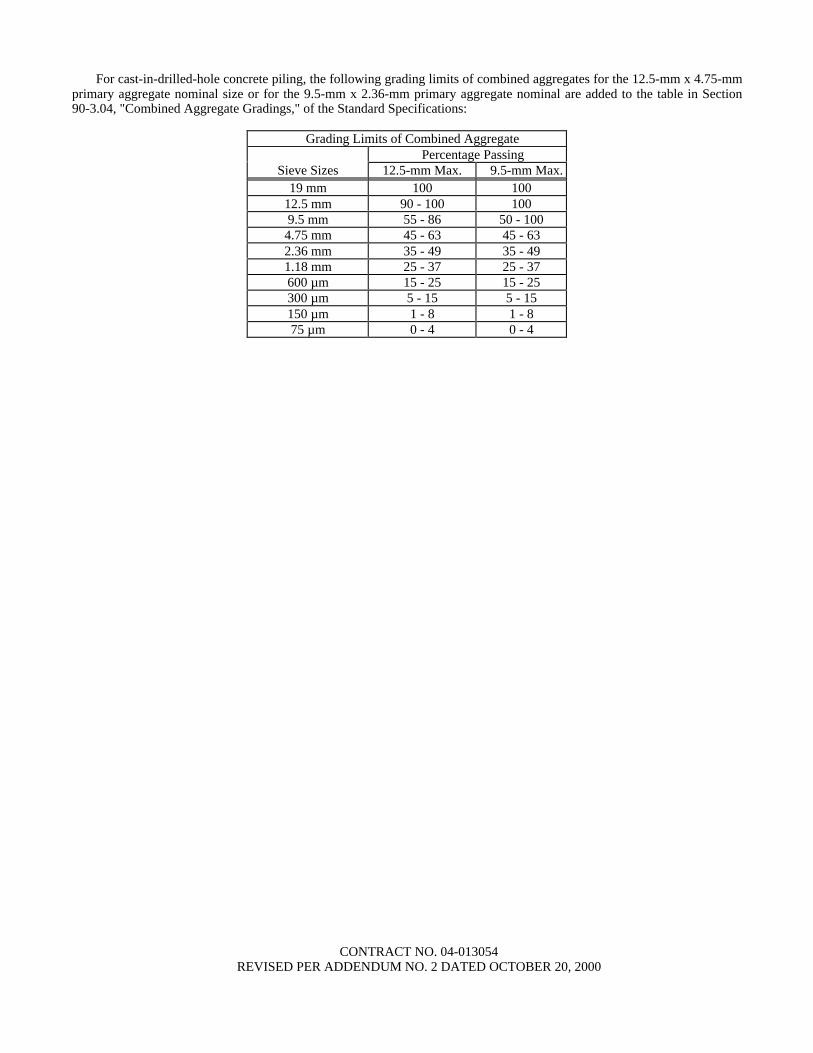
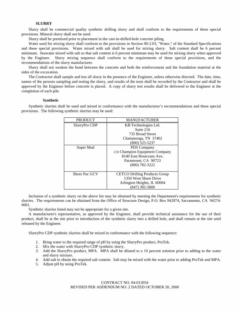
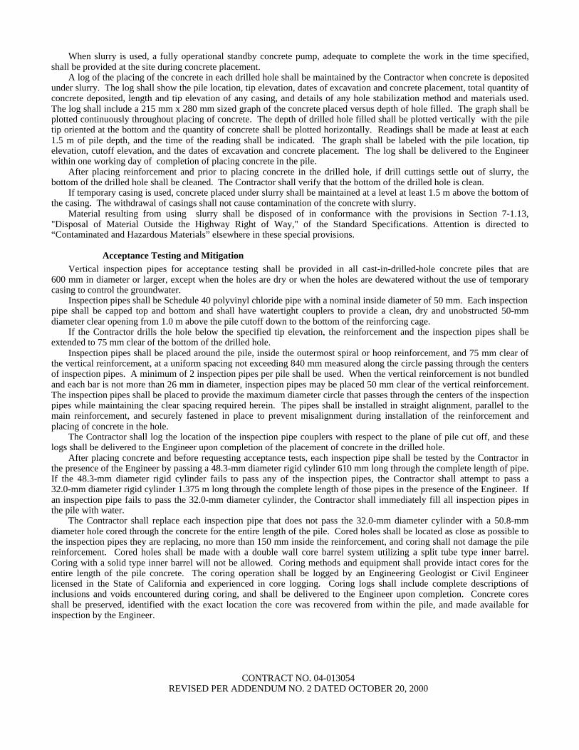
TESTING--
Air and Water supply lines shall be tested in accordance with the provisions in Section 20-503H(1) Method A of the Standard Specifications except that the testing period shall be 4 hours minimum with no leakage or pressure drop
The Contractor shall furnish pipe anchorages to resist thrust forces occurring during testing All leaks shall be repaired and all defective materials shall be replaced by the Contractor at his expense
The air and water lines shall be tested as a unit All water shall be removed from the air line at the completion of testing air and water lines
MEASUREMENT AND PAYMENT--
Measurement and payment for air and water lines for each size listed in the Engineers Estimate shall be made in the same manner as galvanized steel pipe and plastic pipe supply lines in Sections 20-504 Measurement and 20-505 Payment of the Standard Specifications
Full compensation for furnishing and installing outlets steel hangers steel brackets and other fittings testing and checking and hose assemblies shall be considered as included in the contract prices paid per linear foot for the sizes of air and water lines involved and no additional compensation will be allowed therefor
CONTRACT NO 04-013054 ADDED PER ADDENDUM NO 2 DATED OCTOBER 20 2000
10-602 MODIFY WATER LINES-- Water lines identified on the plans shall be of the size shown and shall conform to the details shown on the plans and these special provisions
Working drawings--The Contractor shall submit complete working drawings The working drawings shall be supplemented by manufacturers descriptive data performance data and installation
instructions for the following Working drawings shall be submitted as described elsewhere in these specifications
Pipe Concrete anchors Couplings
For initial review 5 sets of drawings shall be submitted After review 6 sets shall be submitted to the said Office for final approval and use during construction
MATERIALS--
Pipe and fittings for supply lines--Pipe and fittings for supply lines shall conform to the provisions of Section 20-215A Steel Pipe of the Standard Specifications except that the pipe shall be prepared for grooved couplings rather than threaded
Fabricated steel supports and fasteners--Fabricated steel supports and welds shall be in conformance with the details shown on the plans the provisions in Section 75 ldquoMiscellaneous Metalrdquo of the Standard Specifications and these special provisions Bolts and nuts shall be in accordance with Section 55 ldquoSteel Structuresrdquo of the Standard Specifications Anchors shall be resin capsule type
Mechanical couplings--Mechanical pipe couplings shall be self-centering and shall engage and lock in place the grooved pipe and pipe fittings in a positive airtight couple Fittings shall provide some degree of angular pipe deflection contraction and expansion
Coupling housing clamps shall be fabricated in 2 or more parts of malleable iron castings conforming to the specifications in ASTM Designation A47 Grade 32510 Housing clamps shall hold in place a molded synthetic rubber composition air sealing gasket designed so that internal pressure serves to increase the sealrsquos air tightness Couplings shall be coated with a rust inhibiting vinyl alkyd enamel coating
The coupling assembly shall be securely held together by 2 or more trackhead square or ovalneck steel bolts Bolts and nuts shall be heat treated carbon steel and shall be in accordance with the specifications in ASTM Designation A 183 Couplings shall be UL listed for fire protection systems and rated for a working pressure of 6890 kPa
INSTALLATION--
Pipe fittings--Pipe fittings shall be mechanical couplings For mechanical couplings the pipe ends receiving the cut groove mechanical coupling shall be supplied grooved in accordance with the coupling manufacture For grooving on-site pipe shall be prepared in accordance with the coupling manufacturerrsquos specifications using specially designed tools available
Cut groove pipe ends shall be clean and free from indentations projections and roll marks in the area from pipe end to groove for proper gasket sealing
Before couplings are assembled pipe ends and outsides of gaskets shall be lightly coated with cup grease graphite paste or other lubricant recommended by the pipe coupling manufacturer to facilitate installation
The entire coupling installation shall be done in accordance with the manufacturerrsquos latest published literature Painted surfaces damaged as a result of the Contractorrsquos operations shall be repaired by wire brushing the damaged
member to remove all dirt and loose paint and then applying 2 coats of zinc-rich primer Damaged epoxy coating shall be repaired using an epoxy coating compatible with the original fusion bonded coating following the manufacturerrsquos recommendations
A manufacturerrsquos representative shall visit the job site to observe the first installation of mechanical couplings and to train the Contractorrsquos workers so that all mechanical couplings are installed by workmen trained by the manufacturerrsquos representative and that the couplings are installed in accordance with the manufacturerrsquos recommended installation practices
Elbows tees and reducers shall be forged or cast and installed with the same type coupling as the surrounding pipe
Bridge pipe fittings--Bridge pipe shall be supported within the guidelines shown on the plans Piping shall be supported to allow for weight loading thermal and bridge expansion and lateral loading equal to bridge movement
CONTRACT NO 04-013054 ADDED PER ADDENDUM NO 2 DATED OCTOBER 20 2000
Cutting pipe--All pipe shall be cut straight and true and the ends shall be reamed to the full inside diameter of the pipe after cutting
All pipe shall be cut by a power hacksaw a circular cutting machine using an abrasive wheel or in a squire-end saw vise by means of a hand saw The pipe shall be reamed after cutting and rough edges or burrs removed so that a smooth and unobstructed flow will be obtained
Damaged piping--Pipe that is cracked or otherwise damaged shall be removed from the work
Cleaning and closing of pipe--The interior of all pipe shall be cleaned before installation All openings shall be capped or plugged as soon as the pipelines are installed to prevent the entrance of any materials The caps or plugs shall remain in place until their removal is necessary for completion of the installation All completed systems shall be flushed or blown out
TESTING--
Water supply lines shall be tested in accordance with the provisions in Section 20-503H(1) Method A of the Standard Specifications except that the testing period shall be 4 hours minimum with no leakage or pressure drop
The Contractor shall furnish pipe anchorages to resist thrust forces occurring during testing All leaks shall be repaired and all defective materials shall be replaced by the Contractor at his expense
The water lines shall be tested as a unit
MEASUREMENT AND PAYMENT--
Measurement and payment for modify water lines for each size listed in the Engineers Estimate shall be made in the same manner as galvanized steel pipe and plastic pipe supply lines in Sections 20-504 Measurement and 20-505 Payment of the Standard Specifications
Full compensation for relocating outlets steel hangers steel brackets and other fittings testing and checking shall be considered as included in the contract prices paid per linear foot for the sizes of water lines involved and no additional compensation will be allowed therefor
CONTRACT NO 04-013054 ADDED PER ADDENDUM NO 2 DATED OCTOBER 20 2000
ENGINEERS ESTIMATE 04-013054
Item Item Code
Item Unit of Measure
Estimated Quantity
Unit Price Item Total
1 BLANK
2 019451 ELECTRONIC MOBILE DAILY DIARY COMPUTER SYSTEM DATA DELIVERY
LS LUMP SUM LUMP SUM
3 070018 TIME RELATED OVERHEAD LS LUMP SUM LUMP SUM
4 070010 PROGRESS SCHEDULE (CRITICAL PATH)
LS LUMP SUM LUMP SUM
5 019452 NON-STORM WATER DISCHARGE LS LUMP SUM LUMP SUM
6 074019 PREPARE STORM WATER POLLUTION PREVENTION PLAN
LS LUMP SUM LUMP SUM
7 074020 WATER POLLUTION CONTROL LS LUMP SUM LUMP SUM
8 074029 TEMPORARY SILT FENCE M 620
9 019453 TEMPORARY COVER M2 1000
10 019454 TEMPORARY DRAINAGE INLET PROTECTION
EA 73
11 121100 TEMPORARY EROSION CONTROL M2 26 900
12 019455 TEMPORARY CONCRETE WASHOUT EA 10
13 BLANK
14 019457 TEMPORARY ROCK BAG BARRIER M 160
15 019458 TEMPORARY ENTRANCEEXIT LS LUMP SUM LUMP SUM
16 (S)
120090 CONSTRUCTION AREA SIGNS LS LUMP SUM LUMP SUM
17 (S)
120100 TRAFFIC CONTROL SYSTEM LS LUMP SUM LUMP SUM
18 (S)
120120 TYPE III BARRICADE EA 20
19 120149 TEMPORARY PAVEMENT MARKING (PAINT)
M2 35
20 120159 TEMPORARY TRAFFIC STRIPE (PAINT)
M 15 760
3 REVISED PER ADDENDUM NO 2 DATED OCTOBER 20 2000
ENGINEERS ESTIMATE 04-013054
Item Item Code
Item Unit of Measure
Estimated Quantity
Unit Price Item Total
21 120165 CHANNELIZER (SURFACE MOUNTED)
EA 75
22 120300 TEMPORARY PAVEMENT MARKER EA 7530
23 (S)
128650 PORTABLE CHANGEABLE MESSAGE SIGN
EA 8
24 129000 TEMPORARY RAILING (TYPE K) M 11 040
25 129100 TEMPORARY CRASH CUSHION MODULE
EA 130
26 150206 ABANDON CULVERT EA 20
27 150605 REMOVE FENCE M 260
28 150662 REMOVE METAL BEAM GUARD RAILING
M 30
29 150667 REMOVE DOUBLE METAL BEAM BARRIER
M 490
30 150711 REMOVE PAINTED TRAFFIC STRIPE M 9100
31 019459 REMOVE YELLOW PAINTED TRAFFIC STRIPE
M 3170
32 150712 REMOVE PAINTED PAVEMENT MARKING
M2 35
33 150714 REMOVE THERMOPLASTIC TRAFFIC STRIPE
M 1090
34 150174 REMOVE YELLOW THERMOPLASTIC TRAFFIC STRIPE
M 160
35 150715 REMOVE THERMOPLASTIC PAVEMENT MARKING
M2 9
36 150722 REMOVE PAVEMENT MARKER EA 9720
37 150744 REMOVE ROADSIDE SIGN (WOOD POST)
EA 20
38 150747 REMOVE ROADSIDE SIGN (STRAP AND SADDLE BRACKET METHOD)
EA 20
39 150760 REMOVE SIGN STRUCTURE EA 3
40 150805 REMOVE CULVERT M 115
4 REVISED PER ADDENDUM NO 2 DATED OCTOBER 20 2000
ENGINEERS ESTIMATE 04-013054
Item Item Code
Item Unit of Measure
Estimated Quantity
Unit Price Item Total
41 150820 REMOVE INLET EA 22
42 150829 REMOVE RETAINING WALL M3 200
43 150846 REMOVE CONCRETE PAVEMENT M3 3170
44 150857 REMOVE ASPHALT CONCRETE SURFACING
M3 1120
45 150860 REMOVE BASE AND SURFACING M3 6440
46 150870 REMOVE CONCRETE DECK SURFACE
M2 44
47 151264 SALVAGE FENCE M 215
48 151272 SALVAGE METAL BEAM GUARD RAILING
M 80
49 151281 SALVAGE ROADSIDE SIGN EA 7
50 152390 RELOCATE ROADSIDE SIGN EA 9
51 152394 RELOCATE SIGN STRUCTURE EA 2
52 152423 ADJUST MONUMENT TO GRADE EA 1
53 152440 ADJUST MANHOLE TO GRADE EA 1
54 152443 ADJUST PIPE INLET TO GRADE EA 4
55 152609 MODIFY INLET TO MANHOLE EA 1
56 (S)
019460 PLANE ASPHALT CONCRETE PAVEMENT (45MM MAX)
M2 6200
57 (S)
019461 PLANE ASPHALT CONCRETE PAVEMENT (75MM MAX)
M2 10 300
58 153210 REMOVE CONCRETE M3 570
59 153229 REMOVE CONCRETE BARRIER (TYPE K)
M 700
60 155003 CAP INLET EA 5
5 REVISED PER ADDENDUM NO 2 DATED OCTOBER 20 2000
ENGINEERS ESTIMATE 04-013054
Item Item Code
Item Unit of Measure
Estimated Quantity
Unit Price Item Total
61 157551 BRIDGE REMOVAL LOCATION A LS LUMP SUM LUMP SUM
62 157552 BRIDGE REMOVAL LOCATION B LS LUMP SUM LUMP SUM
63 157553 BRIDGE REMOVAL LOCATION C LS LUMP SUM LUMP SUM
64 157564 BRIDGE REMOVAL (PORTION) LOCATION D
LS LUMP SUM LUMP SUM
65 157565 BRIDGE REMOVAL (PORTION) LOCATION E
LS LUMP SUM LUMP SUM
66 158100 SALVAGE CRASH CUSHION EA 2
67 160101 CLEARING AND GRUBBING LS LUMP SUM LUMP SUM
68 190101 ROADWAY EXCAVATION M3 137 500
69 190112 ROADWAY EXCAVATION (TYPE A) M3 9240
70 190185 SHOULDER BACKING STA 2
71 (F)
192003 STRUCTURE EXCAVATION (BRIDGE)
M3 712
72 (F)
192020 STRUCTURE EXCAVATION (TYPE D) M3 8748
73 (F)
192021 STRUCTURE EXCAVATION (TYPE DH)
M3 586
74 (F)
192023 STRUCTURE EXCAVATION (TYPE H) M3 203
75 (F)
192049 STRUCTURE EXCAVATION (SOLDIER PILE WALL)
M3 2125
76 192502 SAND BEDDING M3 76
77 (F)
193003 STRUCTURE BACKFILL (BRIDGE) M3 6058
78 (F)
193029 STRUCTURE BACKFILL (SOLDIER PILE WALL)
M3 690
79 193114 SAND BACKFILL M3 995
80 (F)
193119 LEAN CONCRETE BACKFILL M3 1072
6 REVISED PER ADDENDUM NO 2 DATED OCTOBER 20 2000
ENGINEERS ESTIMATE 04-013054
Item Item Code
Item Unit of Measure
Estimated Quantity
Unit Price Item Total
81 (F)
048329 CLASS 1 CONCRETE BACKFILL M3 1460
82 194001 DITCH EXCAVATION M3 7
83 (F)
197020 EARTH RETAINING STRUCTURE M2 1056
84 198007 IMPORTED MATERIAL (SHOULDER BACKING)
M3 27
85 019462 GEOGRID M2 19 800
86 (S)
200001 HIGHWAY PLANTING LS LUMP SUM LUMP SUM
87 200101 IMPORTED TOPSOIL M3 4560
88 203001 EROSION CONTROL (BLANKET) M2 78
89 (S)
203003 STRAW (EROSION CONTROL) TONN 11
90 (S)
203024 COMPOST (EROSION CONTROL) KG 2160
91 (S)
203014 FIBER (EROSION CONTROL) KG 920
92 (S)
203021 FIBER ROLLS M 4110
93 (S)
203045 PURE LIVE SEED (EROSION CONTROL)
KG 270
94 (S)
203056 COMMERCIAL FERTILIZER (EROSION CONTROL)
KG 330
95 (S)
203061 STABILIZING EMULSION (EROSION CONTROL)
KG 580
96 (S)
204099 PLANT ESTABLISHMENT WORK LS LUMP SUM LUMP SUM
97 (S)
208000 IRRIGATION SYSTEM LS LUMP SUM LUMP SUM
98 048330 NPS 15 SUPPLY LINE (BRIDGE) M 140
99 208039 NPS 4 SUPPLY LINE (BRIDGE) M 140
100 048331 MODIFY NPS 4 SUPPLY LINE (BRIDGE)
M 22
7 REVISED PER ADDENDUM NO 2 DATED OCTOBER 20 2000
ENGINEERS ESTIMATE 04-013054
Item Item Code
Item Unit of Measure
Estimated Quantity
Unit Price Item Total
101 208731 200 MM CORRUGATED HIGH DENSITY POLYETHYLENE PIPE CONDUIT
M 41
102 250401 CLASS 4 AGGREGATE SUBBASE M3 9290
103 260301 CLASS 3 AGGREGATE BASE M3 1390
104 280000 LEAN CONCRETE BASE M3 4970
105 290211 ASPHALT TREATED PERMEABLE BASE
M3 440
106 390095 REPLACE ASPHALT CONCRETE SURFACING
M3 23
107 390155 ASPHALT CONCRETE (TYPE A) TONN 17 070
108 390171 ASPHALT CONCRETE BASE (TYPE A)
TONN 1410
109 394002 PLACE ASPHALT CONCRETE (MISCELLANEOUS AREA)
M2 420
110 394040 PLACE ASPHALT CONCRETE DIKE (TYPE A)
M 1650
111 394048 PLACE ASPHALT CONCRETE DIKE (TYPE E)
M 360
112 394049 PLACE ASPHALT CONCRETE DIKE (TYPE F)
M 350
113 397001 ASPHALTIC EMULSION (PAINT BINDER)
TONN 190
114 401000 CONCRETE PAVEMENT M3 9610
115 048332 DRILLED HOLE (750 MM) M 655
116 048333 DRILLED HOLE (900 MM) M 3108
117 048334 DRILLED HOLE (1000 MM) M 325
118 490505 FURNISH STEEL PILING (HP 250 X 62)
M 312
119 (S)
490506 DRIVE STEEL PILE (HP 250 X 62) EA 21
120 490570 FURNISH STEEL PILING (HP 360 X 174)
M 3613
8 REVISED PER ADDENDUM NO 2 DATED OCTOBER 20 2000
ENGINEERS ESTIMATE 04-013054
Item Item Code
Item Unit of Measure
Estimated Quantity
Unit Price Item Total
121 (S)
490571 DRIVE STEEL PILE (HP 360 X 174) EA 120
122 (S)
490657 600 MM CAST-IN-DRILLED-HOLE CONCRETE PILING
M 5632
123 (S)
490658 750 MM CAST-IN-DRILLED-HOLE CONCRETE PILING
M 1890
124 (S)
490671 24 M CAST-IN-DRILLED-HOLE CONCRETE PILING
M 74
125 (F)
048335 STEEL SOLDIER PILE (W360 X 79) M 1000
126 (F)
048336 STEEL SOLDIER PILE (W360 X 101) M 4624
127 (F)
048337 STEEL SOLDIER PILE (W410 X 114) M 416
128 (F)
048338 STEEL SOLDIER PILE (W410 X 149) M 636
129 (F)
048339 STEEL SOLDIER PILE (W460 X 97) M 175
130 (F)
048340 STEEL SOLDIER PILE (W460 X 128) M 108
131 (F)
048341 STEEL SOLDIER PILE (W530 X 219) M 370
132 (F)
048342 STEEL SOLDIER PILE (W690 X 265) M 265
133 499036 FURNISH CAST-IN-STEEL-SHELL CONCRETE PILING (762 MM)
M 5075
134 (S)
499037 DRIVE CAST-IN-STEEL-SHELL CONCRETE PILE (762 MM)
EA 194
135 (S)
500001 PRESTRESSING CAST-IN-PLACE CONCRETE
LS LUMP SUM LUMP SUM
136 (S)
500050 TIEBACK ANCHOR EA 454
137 (F)
048343 STRUCTURAL CONCRETE FACING M3 485
138 (F)
048344 ARCHITECTURAL SURFACE TREATMENT
M2 502
139 (F)
510051 STRUCTURAL CONCRETE BRIDGE FOOTING
M3 3245
140 (F)
510053 STRUCTURAL CONCRETE BRIDGE M3 21 109
9 REVISED PER ADDENDUM NO 2 DATED OCTOBER 20 2000
ENGINEERS ESTIMATE 04-013054
Item Item Code
Item Unit of Measure
Estimated Quantity
Unit Price Item Total
141 (F)
510086 STRUCTURAL CONCRETE APPROACH SLAB (TYPE N)
M3 190
142 (F)
510502 MINOR CONCRETE (MINOR STRUCTURE)
M3 201
143 BLANK
144 (F)
048345 LIGHTWEIGHT CONCRETE (BRIDGE) M3 1729
145 (F)
511064 FRACTURED RIB TEXTURE M2 920
146 511106 DRILL AND BOND DOWEL M 70
147 (F)
513501 CONCRETE CLOSURE WALL M2 52
148 (S)
518050 PTFE BEARING EA 19
149 (S)
048346 PTFE BEARING (SPHERICAL) EA 48
150 (S)
519127 JOINT SEAL ASSEMBLY (MR 90 MM) M 8
151 (S)
519128 JOINT SEAL ASSEMBLY (MR 100 MM)
M 32
152 (S)
519129 JOINT SEAL ASSEMBLY (MR 101 MM - 160 MM)
M 20
153 (S)
519130 JOINT SEAL ASSEMBLY (MR 161 MM - 240 MM)
M 52
154 (S)
519132 JOINT SEAL ASSEMBLY (MR 321 MM - 400 MM)
M 62
155 (S-F)
520102 BAR REINFORCING STEEL (BRIDGE) KG 4 735 500
156 (S)
048347 WELDED HEADED BAR REINFORCEMENT
EA 47 025
157 (S-F)
520103 BAR REINFORCING STEEL (RETAINING WALL)
KG 87 400
158 (S-F)
520110 BAR REINFORCING STEEL (EPOXY COATED) (BRIDGE)
KG 388 000
159 (F)
530100 SHOTCRETE M3 152
160 (S-F)
550102 STRUCTURAL STEEL (BRIDGE) KG 60 080
10 REVISED PER ADDENDUM NO 2 DATED OCTOBER 20 2000
ENGINEERS ESTIMATE 04-013054
Item Item Code
Item Unit of Measure
Estimated Quantity
Unit Price Item Total
161 (S-F)
550203 FURNISH STRUCTURAL STEEL (BRIDGE)
KG 395 200
162 (S-F)
550204 ERECT STRUCTURAL STEEL (BRIDGE)
KG 395 200
163 (S-F)
048348 ISOLATION CASING KG 12 512
164 (S-F)
560218 FURNISH SIGN STRUCTURE (TRUSS) KG 35 435
165 (S-F)
560219 INSTALL SIGN STRUCTURE (TRUSS) KG 35 435
166 (S)
561009 920 MM CAST-IN-DRILLED-HOLE CONCRETE PILE (SIGN FOUNDATION)
M 44
167 562002 METAL (BARRIER MOUNTED SIGN) KG 160
168 562004 METAL (RAIL MOUNTED SIGN) KG 400
169 566011 ROADSIDE SIGN - ONE POST EA 13
170 566012 ROADSIDE SIGN - TWO POST EA 13
171 568001 INSTALL SIGN (STRAP AND SADDLE BRACKET METHOD)
EA 14
172 568007 INSTALL SIGN OVERLAY M2 28
173 568016 INSTALL SIGN PANEL ON EXISTING FRAME
M2 6
174 (F)
575004 TIMBER LAGGING M3 458
175 048349 CLEAN AND PAINT SOLDIER PILE LS LUMP SUM LUMP SUM
176 (S)
590115 CLEAN AND PAINT STRUCTURAL STEEL
LS LUMP SUM LUMP SUM
177 (S)
590135 SPOT BLAST CLEAN AND PAINT UNDERCOAT
M2 2543
178 (S)
048350 WORK AREA MONITORING (LOCATION A)
LS LUMP SUM LUMP SUM
179 (S)
048351 WORK AREA MONITORING (LOCATION B)
LS LUMP SUM LUMP SUM
180 620901 150 MM ALTERNATIVE PIPE CULVERT
M 08
11 REVISED PER ADDENDUM NO 2 DATED OCTOBER 20 2000
ENGINEERS ESTIMATE 04-013054
Item Item Code
Item Unit of Measure
Estimated Quantity
Unit Price Item Total
181 620904 300 MM ALTERNATIVE PIPE CULVERT
M 2
182 620909 450 MM ALTERNATIVE PIPE CULVERT
M 480
183 620913 600 MM ALTERNATIVE PIPE CULVERT
M 140
184 620924 900 MM ALTERNATIVE PIPE CULVERT
M 355
185 650069 450 MM REINFORCED CONCRETE PIPE
M 940
186 650075 600 MM REINFORCED CONCRETE PIPE
M 390
187 650079 900 MM REINFORCED CONCRETE PIPE
M 86
188 650084 1200 MM REINFORCED CONCRETE PIPE
M 110
189 664009 300 MM CORRUGATED STEEL PIPE (163 MM THICK)
M 34
190 664010 300 MM CORRUGATED STEEL PIPE (201 MM THICK)
M 17
191 664014 450 MM CORRUGATED STEEL PIPE (163 MM THICK)
M 39
192 681134 80 MM PLASTIC PIPE (EDGE DRAIN) M 370
193 682049 CLASS 3 PERMEABLE MATERIAL (BLANKET)
M3 7250
194 685067 200 MM ALTERNATIVE PIPE UNDERDRAIN
M 2970
195 019463 300 MM TRENCH DRAIN M 1890
196 019464 400 MM TRENCH DRAIN M 22
197 703542 300 MM WELDED STEEL PIPE (267 MM THICK)
M 33
198 705336 450 MM ALTERNATIVE FLARED END SECTION
EA 1
199 721009 ROCK SLOPE PROTECTION (FACING METHOD B)
M3 63
200 725001 SACKED CONCRETE SLOPE PROTECTION
M3 16
12 REVISED PER ADDENDUM NO 2 DATED OCTOBER 20 2000
ENGINEERS ESTIMATE 04-013054
Item Item Code
Item Unit of Measure
Estimated Quantity
Unit Price Item Total
201 729010 ROCK SLOPE PROTECTION FABRIC M2 21
202 731502 MINOR CONCRETE (MISCELLANEOUS CONSTRUCTION)
M3 600
203 (F)
731517 MINOR CONCRETE (GUTTER) M 528
204 (S-F)
750001 MISCELLANEOUS IRON AND STEEL KG 11 080
205 (S-F)
750501 MISCELLANEOUS METAL (BRIDGE) KG 54 430
206 (S-F)
750505 BRIDGE DECK DRAINAGE SYSTEM KG 36 160
207 (S-F)
800386 CHAIN LINK FENCE (TYPE CL-12 VINYL-CLAD)
M 300
208 (S)
800391 CHAIN LINK FENCE (TYPE CL-18) M 493
209 (S-F)
800392 CHAIN LINK FENCE (TYPE CL-18 VINYL-CLAD)
M 232
210 (S)
802592 24 M CHAIN LINK GATE (TYPE CL-18)
EA 1
211 (S)
019465 96 M CHAIN LINK GATE (TYPE CL-18)
EA 1
212 019466 48 M CHAIN GATE (TYPE CL-18) EA 1
213 820107 DELINEATOR (CLASS 1) EA 150
214 019467 CONCRETE BARRIER MARKER EA 156
215 820141 OBJECT MARKER (TYPE K-1) EA 1
216 019468 OBJECT MARKER (TYPE Q) EA 6
217 (S)
832002 METAL BEAM GUARD RAILING (STEEL POST)
M 720
218 (S-F)
833032 CHAIN LINK RAILING (TYPE 7) M 4
219 (F)
833125 CONCRETE BARRIER (TYPE 25) M 3267
220 (F)
833165 CONCRETE BARRIER (TYPE 27B MODIFIED)
M 120
13 REVISED PER ADDENDUM NO 2 DATED OCTOBER 20 2000
ENGINEERS ESTIMATE 04-013054
Item Item Code
Item Unit of Measure
Estimated Quantity
Unit Price Item Total
221 (F)
833187 CONCRETE BARRIER (TYPE 27 MODIFIED)
M 471
222 (F)
048352 CONCRETE BARRIER (TYPE 41) M 565
223 (S-F)
048353 BARRIER MOUNTED BRIDGE RAILING
M 591
224 (S-F)
048354 PEDESTRIAN RAILING M 584
225 (S)
839559 TERMINAL SYSTEM (TYPE ET) EA 1
226 (S)
839565 TERMINAL SYSTEM (TYPE SRT) EA 15
227 (S)
839591 CRASH CUSHION SAND FILLED EA 2
228 839701 CONCRETE BARRIER (TYPE 60) M 140
229 839702 CONCRETE BARRIER (TYPE 60A) M 1215
230 (F)
839704 CONCRETE BARRIER (TYPE 60D) M 300
231 (S)
840515 THERMOPLASTIC PAVEMENT MARKING
M2 325
232 (S)
840561 100 MM THERMOPLASTIC TRAFFIC STRIPE
M 14 550
233 (S)
840563 200 MM THERMOPLASTIC TRAFFIC STRIPE
M 1925
234 (S)
840571 100 MM THERMOPLASTIC TRAFFIC STRIPE (BROKEN 518 M - 214 M)
M 91
235 (S)
850101 PAVEMENT MARKER (NON-REFLECTIVE)
EA 3300
236 (S)
850111 PAVEMENT MARKER (RETROREFLECTIVE)
EA 1860
237 (S)
860201 SIGNAL AND LIGHTING LS LUMP SUM LUMP SUM
238 (S)
019469 LIGHTING STAGE CONSTRUCTION-LOCATION 1
LS LUMP SUM LUMP SUM
239 (S)
019470 LIGHTING STAGE CONSTRUCTION-LOCATION 2
LS LUMP SUM LUMP SUM
240 (S)
019471 LIGHTING AND SIGN ILLUMINATION AND TRAFFIC OPERATIONS SYSTEM STAGE CONSTRUCTION- LOCATION 3
LS LUMP SUM LUMP SUM
14 REVISED PER ADDENDUM NO 2 DATED OCTOBER 20 2000
ENGINEERS ESTIMATE 04-013054
Item Item Code
Item Unit of Measure
Estimated Quantity
Unit Price Item Total
241 (S)
019472 SIGNAL AND LIGHTING STAGE CONSTRUCTION-LOCATION 4
LS LUMP SUM LUMP SUM
242 (S)
860462 LIGHTING (LOCATION 2) LS LUMP SUM LUMP SUM
243 (S)
860551 LIGHTING AND SIGN ILLUMINATION (LOCATION 1)
LS LUMP SUM LUMP SUM
244 (S)
019473 CAMERA UNIT EA 1
245 (S)
019474 PANTILT UNIT EA 1
246 (S)
019475 CAMERA CONTROL UNIT EA 1
247 (S)
019476 VIDEO ENCODER UNIT EA 1
248 (S)
019477 INTEGRATED SERVICE DIGITAL NETWORK TERMINAL ADAPTER
EA 1
249 (S)
019478 CLUSTER CONTROLLER FOR MICROWAVE VEHICLE DETECTION SENSOR SYSTEM
EA 1
250 (S)
019479 ANALOG DATA STATION TERMINATION
EA 1
251 (S)
019480 TRAFFIC OPERATIONS SYSTEM (LOCATION-1)
LS LUMP SUM LUMP SUM
252 (S)
019481 TRAFFIC OPERATIONS SYSTEM (LOCATION-2)
LS LUMP SUM LUMP SUM
253 (S)
019482 TRAFFIC OPERATIONS SYSTEM (LOCATION-3)
LS LUMP SUM LUMP SUM
254 (S)
019483 CALLBOX SYSTEM LS LUMP SUM LUMP SUM
255 (S)
869072 SEISMIC MONITORING SYSTEM LS LUMP SUM LUMP SUM
256 (S)
048355 INSTALL SEISMIC MONITORING CASING
M 184
257 BLANK
258 020059 50 MM PERFORATED PLASTIC PIPE M 1571
259 020060 50 MM PLASTIC PIPE M 272
260 BLANK
15 REVISED PER ADDENDUM NO 2 DATED OCTOBER 20 2000
ENGINEERS ESTIMATE 04-013054
Item Item Code
Item Unit of Measure
Estimated Quantity
Unit Price Item Total
261 020131 REMOVE CHAIN LINK GATE EA 3
262 193001 STRUCTURE BACKFILL M3 22 600
263 020132 STRUCTURE BACKFILL (TYPE E)
M3 20 500
264 685062 150MM ALTERNATIVE PIPE UNDERDRAIN
M 230
265 999990 MOBILIZATION LS LUMP SUM LUMP SUM
15A ADDED PER ADDENDUM NO 2 DATED OCTOBER 20 2000
ENGINEERS ESTIMATE 04-013054
TOTAL BID (A) =
TOTAL BID (B) $ 3500000 X ____________________ =
(Cost Per Day) (Working Days Bid For Phase II Work) (Not To Exceed 610 Days)
BASIS FOR COMPARISON OF BIDS (A) + (B) =
Notes
1 TOTAL BID (A) is the grand total of the Item Totals in the Engineers Estimate
2 Working Days Bid is defined in the Special Provisions
16 REVISED PER ADDENDUM NO 2 DATED OCTOBER 20 2000

ENGINEERS ESTIMATE 04-013054
Item Item Code
Item Unit of Measure
Estimated Quantity
Unit Price Item Total
1 BLANK
2 019451 ELECTRONIC MOBILE DAILY DIARY COMPUTER SYSTEM DATA DELIVERY
LS LUMP SUM LUMP SUM
3 070018 TIME RELATED OVERHEAD LS LUMP SUM LUMP SUM
4 070010 PROGRESS SCHEDULE (CRITICAL PATH)
LS LUMP SUM LUMP SUM
5 019452 NON-STORM WATER DISCHARGE LS LUMP SUM LUMP SUM
6 074019 PREPARE STORM WATER POLLUTION PREVENTION PLAN
LS LUMP SUM LUMP SUM
7 074020 WATER POLLUTION CONTROL LS LUMP SUM LUMP SUM
8 074029 TEMPORARY SILT FENCE M 620
9 019453 TEMPORARY COVER M2 1000
10 019454 TEMPORARY DRAINAGE INLET PROTECTION
EA 73
11 121100 TEMPORARY EROSION CONTROL M2 26 900
12 019455 TEMPORARY CONCRETE WASHOUT EA 10
13 BLANK
14 019457 TEMPORARY ROCK BAG BARRIER M 160
15 019458 TEMPORARY ENTRANCEEXIT LS LUMP SUM LUMP SUM
16 (S)
120090 CONSTRUCTION AREA SIGNS LS LUMP SUM LUMP SUM
17 (S)
120100 TRAFFIC CONTROL SYSTEM LS LUMP SUM LUMP SUM
18 (S)
120120 TYPE III BARRICADE EA 20
19 120149 TEMPORARY PAVEMENT MARKING (PAINT)
M2 35
20 120159 TEMPORARY TRAFFIC STRIPE (PAINT)
M 15 760
3 REVISED PER ADDENDUM NO 2 DATED OCTOBER 20 2000
ENGINEERS ESTIMATE 04-013054
Item Item Code
Item Unit of Measure
Estimated Quantity
Unit Price Item Total
21 120165 CHANNELIZER (SURFACE MOUNTED)
EA 75
22 120300 TEMPORARY PAVEMENT MARKER EA 7530
23 (S)
128650 PORTABLE CHANGEABLE MESSAGE SIGN
EA 8
24 129000 TEMPORARY RAILING (TYPE K) M 11 040
25 129100 TEMPORARY CRASH CUSHION MODULE
EA 130
26 150206 ABANDON CULVERT EA 20
27 150605 REMOVE FENCE M 260
28 150662 REMOVE METAL BEAM GUARD RAILING
M 30
29 150667 REMOVE DOUBLE METAL BEAM BARRIER
M 490
30 150711 REMOVE PAINTED TRAFFIC STRIPE M 9100
31 019459 REMOVE YELLOW PAINTED TRAFFIC STRIPE
M 3170
32 150712 REMOVE PAINTED PAVEMENT MARKING
M2 35
33 150714 REMOVE THERMOPLASTIC TRAFFIC STRIPE
M 1090
34 150174 REMOVE YELLOW THERMOPLASTIC TRAFFIC STRIPE
M 160
35 150715 REMOVE THERMOPLASTIC PAVEMENT MARKING
M2 9
36 150722 REMOVE PAVEMENT MARKER EA 9720
37 150744 REMOVE ROADSIDE SIGN (WOOD POST)
EA 20
38 150747 REMOVE ROADSIDE SIGN (STRAP AND SADDLE BRACKET METHOD)
EA 20
39 150760 REMOVE SIGN STRUCTURE EA 3
40 150805 REMOVE CULVERT M 115
4 REVISED PER ADDENDUM NO 2 DATED OCTOBER 20 2000
ENGINEERS ESTIMATE 04-013054
Item Item Code
Item Unit of Measure
Estimated Quantity
Unit Price Item Total
41 150820 REMOVE INLET EA 22
42 150829 REMOVE RETAINING WALL M3 200
43 150846 REMOVE CONCRETE PAVEMENT M3 3170
44 150857 REMOVE ASPHALT CONCRETE SURFACING
M3 1120
45 150860 REMOVE BASE AND SURFACING M3 6440
46 150870 REMOVE CONCRETE DECK SURFACE
M2 44
47 151264 SALVAGE FENCE M 215
48 151272 SALVAGE METAL BEAM GUARD RAILING
M 80
49 151281 SALVAGE ROADSIDE SIGN EA 7
50 152390 RELOCATE ROADSIDE SIGN EA 9
51 152394 RELOCATE SIGN STRUCTURE EA 2
52 152423 ADJUST MONUMENT TO GRADE EA 1
53 152440 ADJUST MANHOLE TO GRADE EA 1
54 152443 ADJUST PIPE INLET TO GRADE EA 4
55 152609 MODIFY INLET TO MANHOLE EA 1
56 (S)
019460 PLANE ASPHALT CONCRETE PAVEMENT (45MM MAX)
M2 6200
57 (S)
019461 PLANE ASPHALT CONCRETE PAVEMENT (75MM MAX)
M2 10 300
58 153210 REMOVE CONCRETE M3 570
59 153229 REMOVE CONCRETE BARRIER (TYPE K)
M 700
60 155003 CAP INLET EA 5
5 REVISED PER ADDENDUM NO 2 DATED OCTOBER 20 2000
ENGINEERS ESTIMATE 04-013054
Item Item Code
Item Unit of Measure
Estimated Quantity
Unit Price Item Total
61 157551 BRIDGE REMOVAL LOCATION A LS LUMP SUM LUMP SUM
62 157552 BRIDGE REMOVAL LOCATION B LS LUMP SUM LUMP SUM
63 157553 BRIDGE REMOVAL LOCATION C LS LUMP SUM LUMP SUM
64 157564 BRIDGE REMOVAL (PORTION) LOCATION D
LS LUMP SUM LUMP SUM
65 157565 BRIDGE REMOVAL (PORTION) LOCATION E
LS LUMP SUM LUMP SUM
66 158100 SALVAGE CRASH CUSHION EA 2
67 160101 CLEARING AND GRUBBING LS LUMP SUM LUMP SUM
68 190101 ROADWAY EXCAVATION M3 137 500
69 190112 ROADWAY EXCAVATION (TYPE A) M3 9240
70 190185 SHOULDER BACKING STA 2
71 (F)
192003 STRUCTURE EXCAVATION (BRIDGE)
M3 712
72 (F)
192020 STRUCTURE EXCAVATION (TYPE D) M3 8748
73 (F)
192021 STRUCTURE EXCAVATION (TYPE DH)
M3 586
74 (F)
192023 STRUCTURE EXCAVATION (TYPE H) M3 203
75 (F)
192049 STRUCTURE EXCAVATION (SOLDIER PILE WALL)
M3 2125
76 192502 SAND BEDDING M3 76
77 (F)
193003 STRUCTURE BACKFILL (BRIDGE) M3 6058
78 (F)
193029 STRUCTURE BACKFILL (SOLDIER PILE WALL)
M3 690
79 193114 SAND BACKFILL M3 995
80 (F)
193119 LEAN CONCRETE BACKFILL M3 1072
6 REVISED PER ADDENDUM NO 2 DATED OCTOBER 20 2000
ENGINEERS ESTIMATE 04-013054
Item Item Code
Item Unit of Measure
Estimated Quantity
Unit Price Item Total
81 (F)
048329 CLASS 1 CONCRETE BACKFILL M3 1460
82 194001 DITCH EXCAVATION M3 7
83 (F)
197020 EARTH RETAINING STRUCTURE M2 1056
84 198007 IMPORTED MATERIAL (SHOULDER BACKING)
M3 27
85 019462 GEOGRID M2 19 800
86 (S)
200001 HIGHWAY PLANTING LS LUMP SUM LUMP SUM
87 200101 IMPORTED TOPSOIL M3 4560
88 203001 EROSION CONTROL (BLANKET) M2 78
89 (S)
203003 STRAW (EROSION CONTROL) TONN 11
90 (S)
203024 COMPOST (EROSION CONTROL) KG 2160
91 (S)
203014 FIBER (EROSION CONTROL) KG 920
92 (S)
203021 FIBER ROLLS M 4110
93 (S)
203045 PURE LIVE SEED (EROSION CONTROL)
KG 270
94 (S)
203056 COMMERCIAL FERTILIZER (EROSION CONTROL)
KG 330
95 (S)
203061 STABILIZING EMULSION (EROSION CONTROL)
KG 580
96 (S)
204099 PLANT ESTABLISHMENT WORK LS LUMP SUM LUMP SUM
97 (S)
208000 IRRIGATION SYSTEM LS LUMP SUM LUMP SUM
98 048330 NPS 15 SUPPLY LINE (BRIDGE) M 140
99 208039 NPS 4 SUPPLY LINE (BRIDGE) M 140
100 048331 MODIFY NPS 4 SUPPLY LINE (BRIDGE)
M 22
7 REVISED PER ADDENDUM NO 2 DATED OCTOBER 20 2000
ENGINEERS ESTIMATE 04-013054
Item Item Code
Item Unit of Measure
Estimated Quantity
Unit Price Item Total
101 208731 200 MM CORRUGATED HIGH DENSITY POLYETHYLENE PIPE CONDUIT
M 41
102 250401 CLASS 4 AGGREGATE SUBBASE M3 9290
103 260301 CLASS 3 AGGREGATE BASE M3 1390
104 280000 LEAN CONCRETE BASE M3 4970
105 290211 ASPHALT TREATED PERMEABLE BASE
M3 440
106 390095 REPLACE ASPHALT CONCRETE SURFACING
M3 23
107 390155 ASPHALT CONCRETE (TYPE A) TONN 17 070
108 390171 ASPHALT CONCRETE BASE (TYPE A)
TONN 1410
109 394002 PLACE ASPHALT CONCRETE (MISCELLANEOUS AREA)
M2 420
110 394040 PLACE ASPHALT CONCRETE DIKE (TYPE A)
M 1650
111 394048 PLACE ASPHALT CONCRETE DIKE (TYPE E)
M 360
112 394049 PLACE ASPHALT CONCRETE DIKE (TYPE F)
M 350
113 397001 ASPHALTIC EMULSION (PAINT BINDER)
TONN 190
114 401000 CONCRETE PAVEMENT M3 9610
115 048332 DRILLED HOLE (750 MM) M 655
116 048333 DRILLED HOLE (900 MM) M 3108
117 048334 DRILLED HOLE (1000 MM) M 325
118 490505 FURNISH STEEL PILING (HP 250 X 62)
M 312
119 (S)
490506 DRIVE STEEL PILE (HP 250 X 62) EA 21
120 490570 FURNISH STEEL PILING (HP 360 X 174)
M 3613
8 REVISED PER ADDENDUM NO 2 DATED OCTOBER 20 2000
ENGINEERS ESTIMATE 04-013054
Item Item Code
Item Unit of Measure
Estimated Quantity
Unit Price Item Total
121 (S)
490571 DRIVE STEEL PILE (HP 360 X 174) EA 120
122 (S)
490657 600 MM CAST-IN-DRILLED-HOLE CONCRETE PILING
M 5632
123 (S)
490658 750 MM CAST-IN-DRILLED-HOLE CONCRETE PILING
M 1890
124 (S)
490671 24 M CAST-IN-DRILLED-HOLE CONCRETE PILING
M 74
125 (F)
048335 STEEL SOLDIER PILE (W360 X 79) M 1000
126 (F)
048336 STEEL SOLDIER PILE (W360 X 101) M 4624
127 (F)
048337 STEEL SOLDIER PILE (W410 X 114) M 416
128 (F)
048338 STEEL SOLDIER PILE (W410 X 149) M 636
129 (F)
048339 STEEL SOLDIER PILE (W460 X 97) M 175
130 (F)
048340 STEEL SOLDIER PILE (W460 X 128) M 108
131 (F)
048341 STEEL SOLDIER PILE (W530 X 219) M 370
132 (F)
048342 STEEL SOLDIER PILE (W690 X 265) M 265
133 499036 FURNISH CAST-IN-STEEL-SHELL CONCRETE PILING (762 MM)
M 5075
134 (S)
499037 DRIVE CAST-IN-STEEL-SHELL CONCRETE PILE (762 MM)
EA 194
135 (S)
500001 PRESTRESSING CAST-IN-PLACE CONCRETE
LS LUMP SUM LUMP SUM
136 (S)
500050 TIEBACK ANCHOR EA 454
137 (F)
048343 STRUCTURAL CONCRETE FACING M3 485
138 (F)
048344 ARCHITECTURAL SURFACE TREATMENT
M2 502
139 (F)
510051 STRUCTURAL CONCRETE BRIDGE FOOTING
M3 3245
140 (F)
510053 STRUCTURAL CONCRETE BRIDGE M3 21 109
9 REVISED PER ADDENDUM NO 2 DATED OCTOBER 20 2000
ENGINEERS ESTIMATE 04-013054
Item Item Code
Item Unit of Measure
Estimated Quantity
Unit Price Item Total
141 (F)
510086 STRUCTURAL CONCRETE APPROACH SLAB (TYPE N)
M3 190
142 (F)
510502 MINOR CONCRETE (MINOR STRUCTURE)
M3 201
143 BLANK
144 (F)
048345 LIGHTWEIGHT CONCRETE (BRIDGE) M3 1729
145 (F)
511064 FRACTURED RIB TEXTURE M2 920
146 511106 DRILL AND BOND DOWEL M 70
147 (F)
513501 CONCRETE CLOSURE WALL M2 52
148 (S)
518050 PTFE BEARING EA 19
149 (S)
048346 PTFE BEARING (SPHERICAL) EA 48
150 (S)
519127 JOINT SEAL ASSEMBLY (MR 90 MM) M 8
151 (S)
519128 JOINT SEAL ASSEMBLY (MR 100 MM)
M 32
152 (S)
519129 JOINT SEAL ASSEMBLY (MR 101 MM - 160 MM)
M 20
153 (S)
519130 JOINT SEAL ASSEMBLY (MR 161 MM - 240 MM)
M 52
154 (S)
519132 JOINT SEAL ASSEMBLY (MR 321 MM - 400 MM)
M 62
155 (S-F)
520102 BAR REINFORCING STEEL (BRIDGE) KG 4 735 500
156 (S)
048347 WELDED HEADED BAR REINFORCEMENT
EA 47 025
157 (S-F)
520103 BAR REINFORCING STEEL (RETAINING WALL)
KG 87 400
158 (S-F)
520110 BAR REINFORCING STEEL (EPOXY COATED) (BRIDGE)
KG 388 000
159 (F)
530100 SHOTCRETE M3 152
160 (S-F)
550102 STRUCTURAL STEEL (BRIDGE) KG 60 080
10 REVISED PER ADDENDUM NO 2 DATED OCTOBER 20 2000
ENGINEERS ESTIMATE 04-013054
Item Item Code
Item Unit of Measure
Estimated Quantity
Unit Price Item Total
161 (S-F)
550203 FURNISH STRUCTURAL STEEL (BRIDGE)
KG 395 200
162 (S-F)
550204 ERECT STRUCTURAL STEEL (BRIDGE)
KG 395 200
163 (S-F)
048348 ISOLATION CASING KG 12 512
164 (S-F)
560218 FURNISH SIGN STRUCTURE (TRUSS) KG 35 435
165 (S-F)
560219 INSTALL SIGN STRUCTURE (TRUSS) KG 35 435
166 (S)
561009 920 MM CAST-IN-DRILLED-HOLE CONCRETE PILE (SIGN FOUNDATION)
M 44
167 562002 METAL (BARRIER MOUNTED SIGN) KG 160
168 562004 METAL (RAIL MOUNTED SIGN) KG 400
169 566011 ROADSIDE SIGN - ONE POST EA 13
170 566012 ROADSIDE SIGN - TWO POST EA 13
171 568001 INSTALL SIGN (STRAP AND SADDLE BRACKET METHOD)
EA 14
172 568007 INSTALL SIGN OVERLAY M2 28
173 568016 INSTALL SIGN PANEL ON EXISTING FRAME
M2 6
174 (F)
575004 TIMBER LAGGING M3 458
175 048349 CLEAN AND PAINT SOLDIER PILE LS LUMP SUM LUMP SUM
176 (S)
590115 CLEAN AND PAINT STRUCTURAL STEEL
LS LUMP SUM LUMP SUM
177 (S)
590135 SPOT BLAST CLEAN AND PAINT UNDERCOAT
M2 2543
178 (S)
048350 WORK AREA MONITORING (LOCATION A)
LS LUMP SUM LUMP SUM
179 (S)
048351 WORK AREA MONITORING (LOCATION B)
LS LUMP SUM LUMP SUM
180 620901 150 MM ALTERNATIVE PIPE CULVERT
M 08
11 REVISED PER ADDENDUM NO 2 DATED OCTOBER 20 2000
ENGINEERS ESTIMATE 04-013054
Item Item Code
Item Unit of Measure
Estimated Quantity
Unit Price Item Total
181 620904 300 MM ALTERNATIVE PIPE CULVERT
M 2
182 620909 450 MM ALTERNATIVE PIPE CULVERT
M 480
183 620913 600 MM ALTERNATIVE PIPE CULVERT
M 140
184 620924 900 MM ALTERNATIVE PIPE CULVERT
M 355
185 650069 450 MM REINFORCED CONCRETE PIPE
M 940
186 650075 600 MM REINFORCED CONCRETE PIPE
M 390
187 650079 900 MM REINFORCED CONCRETE PIPE
M 86
188 650084 1200 MM REINFORCED CONCRETE PIPE
M 110
189 664009 300 MM CORRUGATED STEEL PIPE (163 MM THICK)
M 34
190 664010 300 MM CORRUGATED STEEL PIPE (201 MM THICK)
M 17
191 664014 450 MM CORRUGATED STEEL PIPE (163 MM THICK)
M 39
192 681134 80 MM PLASTIC PIPE (EDGE DRAIN) M 370
193 682049 CLASS 3 PERMEABLE MATERIAL (BLANKET)
M3 7250
194 685067 200 MM ALTERNATIVE PIPE UNDERDRAIN
M 2970
195 019463 300 MM TRENCH DRAIN M 1890
196 019464 400 MM TRENCH DRAIN M 22
197 703542 300 MM WELDED STEEL PIPE (267 MM THICK)
M 33
198 705336 450 MM ALTERNATIVE FLARED END SECTION
EA 1
199 721009 ROCK SLOPE PROTECTION (FACING METHOD B)
M3 63
200 725001 SACKED CONCRETE SLOPE PROTECTION
M3 16
12 REVISED PER ADDENDUM NO 2 DATED OCTOBER 20 2000
ENGINEERS ESTIMATE 04-013054
Item Item Code
Item Unit of Measure
Estimated Quantity
Unit Price Item Total
201 729010 ROCK SLOPE PROTECTION FABRIC M2 21
202 731502 MINOR CONCRETE (MISCELLANEOUS CONSTRUCTION)
M3 600
203 (F)
731517 MINOR CONCRETE (GUTTER) M 528
204 (S-F)
750001 MISCELLANEOUS IRON AND STEEL KG 11 080
205 (S-F)
750501 MISCELLANEOUS METAL (BRIDGE) KG 54 430
206 (S-F)
750505 BRIDGE DECK DRAINAGE SYSTEM KG 36 160
207 (S-F)
800386 CHAIN LINK FENCE (TYPE CL-12 VINYL-CLAD)
M 300
208 (S)
800391 CHAIN LINK FENCE (TYPE CL-18) M 493
209 (S-F)
800392 CHAIN LINK FENCE (TYPE CL-18 VINYL-CLAD)
M 232
210 (S)
802592 24 M CHAIN LINK GATE (TYPE CL-18)
EA 1
211 (S)
019465 96 M CHAIN LINK GATE (TYPE CL-18)
EA 1
212 019466 48 M CHAIN GATE (TYPE CL-18) EA 1
213 820107 DELINEATOR (CLASS 1) EA 150
214 019467 CONCRETE BARRIER MARKER EA 156
215 820141 OBJECT MARKER (TYPE K-1) EA 1
216 019468 OBJECT MARKER (TYPE Q) EA 6
217 (S)
832002 METAL BEAM GUARD RAILING (STEEL POST)
M 720
218 (S-F)
833032 CHAIN LINK RAILING (TYPE 7) M 4
219 (F)
833125 CONCRETE BARRIER (TYPE 25) M 3267
220 (F)
833165 CONCRETE BARRIER (TYPE 27B MODIFIED)
M 120
13 REVISED PER ADDENDUM NO 2 DATED OCTOBER 20 2000
ENGINEERS ESTIMATE 04-013054
Item Item Code
Item Unit of Measure
Estimated Quantity
Unit Price Item Total
221 (F)
833187 CONCRETE BARRIER (TYPE 27 MODIFIED)
M 471
222 (F)
048352 CONCRETE BARRIER (TYPE 41) M 565
223 (S-F)
048353 BARRIER MOUNTED BRIDGE RAILING
M 591
224 (S-F)
048354 PEDESTRIAN RAILING M 584
225 (S)
839559 TERMINAL SYSTEM (TYPE ET) EA 1
226 (S)
839565 TERMINAL SYSTEM (TYPE SRT) EA 15
227 (S)
839591 CRASH CUSHION SAND FILLED EA 2
228 839701 CONCRETE BARRIER (TYPE 60) M 140
229 839702 CONCRETE BARRIER (TYPE 60A) M 1215
230 (F)
839704 CONCRETE BARRIER (TYPE 60D) M 300
231 (S)
840515 THERMOPLASTIC PAVEMENT MARKING
M2 325
232 (S)
840561 100 MM THERMOPLASTIC TRAFFIC STRIPE
M 14 550
233 (S)
840563 200 MM THERMOPLASTIC TRAFFIC STRIPE
M 1925
234 (S)
840571 100 MM THERMOPLASTIC TRAFFIC STRIPE (BROKEN 518 M - 214 M)
M 91
235 (S)
850101 PAVEMENT MARKER (NON-REFLECTIVE)
EA 3300
236 (S)
850111 PAVEMENT MARKER (RETROREFLECTIVE)
EA 1860
237 (S)
860201 SIGNAL AND LIGHTING LS LUMP SUM LUMP SUM
238 (S)
019469 LIGHTING STAGE CONSTRUCTION-LOCATION 1
LS LUMP SUM LUMP SUM
239 (S)
019470 LIGHTING STAGE CONSTRUCTION-LOCATION 2
LS LUMP SUM LUMP SUM
240 (S)
019471 LIGHTING AND SIGN ILLUMINATION AND TRAFFIC OPERATIONS SYSTEM STAGE CONSTRUCTION- LOCATION 3
LS LUMP SUM LUMP SUM
14 REVISED PER ADDENDUM NO 2 DATED OCTOBER 20 2000
ENGINEERS ESTIMATE 04-013054
Item Item Code
Item Unit of Measure
Estimated Quantity
Unit Price Item Total
241 (S)
019472 SIGNAL AND LIGHTING STAGE CONSTRUCTION-LOCATION 4
LS LUMP SUM LUMP SUM
242 (S)
860462 LIGHTING (LOCATION 2) LS LUMP SUM LUMP SUM
243 (S)
860551 LIGHTING AND SIGN ILLUMINATION (LOCATION 1)
LS LUMP SUM LUMP SUM
244 (S)
019473 CAMERA UNIT EA 1
245 (S)
019474 PANTILT UNIT EA 1
246 (S)
019475 CAMERA CONTROL UNIT EA 1
247 (S)
019476 VIDEO ENCODER UNIT EA 1
248 (S)
019477 INTEGRATED SERVICE DIGITAL NETWORK TERMINAL ADAPTER
EA 1
249 (S)
019478 CLUSTER CONTROLLER FOR MICROWAVE VEHICLE DETECTION SENSOR SYSTEM
EA 1
250 (S)
019479 ANALOG DATA STATION TERMINATION
EA 1
251 (S)
019480 TRAFFIC OPERATIONS SYSTEM (LOCATION-1)
LS LUMP SUM LUMP SUM
252 (S)
019481 TRAFFIC OPERATIONS SYSTEM (LOCATION-2)
LS LUMP SUM LUMP SUM
253 (S)
019482 TRAFFIC OPERATIONS SYSTEM (LOCATION-3)
LS LUMP SUM LUMP SUM
254 (S)
019483 CALLBOX SYSTEM LS LUMP SUM LUMP SUM
255 (S)
869072 SEISMIC MONITORING SYSTEM LS LUMP SUM LUMP SUM
256 (S)
048355 INSTALL SEISMIC MONITORING CASING
M 184
257 BLANK
258 020059 50 MM PERFORATED PLASTIC PIPE M 1571
259 020060 50 MM PLASTIC PIPE M 272
260 BLANK
15 REVISED PER ADDENDUM NO 2 DATED OCTOBER 20 2000
ENGINEERS ESTIMATE 04-013054
Item Item Code
Item Unit of Measure
Estimated Quantity
Unit Price Item Total
261 020131 REMOVE CHAIN LINK GATE EA 3
262 193001 STRUCTURE BACKFILL M3 22 600
263 020132 STRUCTURE BACKFILL (TYPE E)
M3 20 500
264 685062 150MM ALTERNATIVE PIPE UNDERDRAIN
M 230
265 999990 MOBILIZATION LS LUMP SUM LUMP SUM
15A ADDED PER ADDENDUM NO 2 DATED OCTOBER 20 2000
ENGINEERS ESTIMATE 04-013054
TOTAL BID (A) =
TOTAL BID (B) $ 3500000 X ____________________ =
(Cost Per Day) (Working Days Bid For Phase II Work) (Not To Exceed 610 Days)
BASIS FOR COMPARISON OF BIDS (A) + (B) =
Notes
1 TOTAL BID (A) is the grand total of the Item Totals in the Engineers Estimate
2 Working Days Bid is defined in the Special Provisions
16 REVISED PER ADDENDUM NO 2 DATED OCTOBER 20 2000
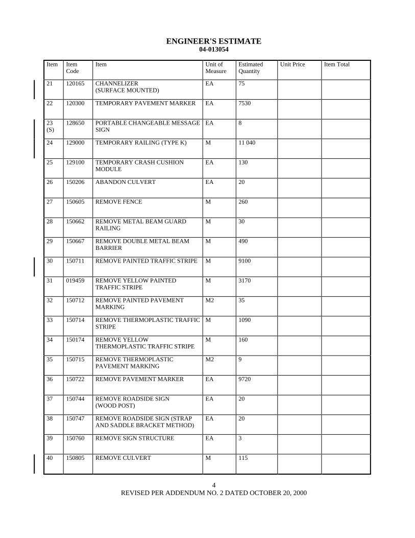
ENGINEERS ESTIMATE 04-013054
Item Item Code
Item Unit of Measure
Estimated Quantity
Unit Price Item Total
41 150820 REMOVE INLET EA 22
42 150829 REMOVE RETAINING WALL M3 200
43 150846 REMOVE CONCRETE PAVEMENT M3 3170
44 150857 REMOVE ASPHALT CONCRETE SURFACING
M3 1120
45 150860 REMOVE BASE AND SURFACING M3 6440
46 150870 REMOVE CONCRETE DECK SURFACE
M2 44
47 151264 SALVAGE FENCE M 215
48 151272 SALVAGE METAL BEAM GUARD RAILING
M 80
49 151281 SALVAGE ROADSIDE SIGN EA 7
50 152390 RELOCATE ROADSIDE SIGN EA 9
51 152394 RELOCATE SIGN STRUCTURE EA 2
52 152423 ADJUST MONUMENT TO GRADE EA 1
53 152440 ADJUST MANHOLE TO GRADE EA 1
54 152443 ADJUST PIPE INLET TO GRADE EA 4
55 152609 MODIFY INLET TO MANHOLE EA 1
56 (S)
019460 PLANE ASPHALT CONCRETE PAVEMENT (45MM MAX)
M2 6200
57 (S)
019461 PLANE ASPHALT CONCRETE PAVEMENT (75MM MAX)
M2 10 300
58 153210 REMOVE CONCRETE M3 570
59 153229 REMOVE CONCRETE BARRIER (TYPE K)
M 700
60 155003 CAP INLET EA 5
5 REVISED PER ADDENDUM NO 2 DATED OCTOBER 20 2000
ENGINEERS ESTIMATE 04-013054
Item Item Code
Item Unit of Measure
Estimated Quantity
Unit Price Item Total
61 157551 BRIDGE REMOVAL LOCATION A LS LUMP SUM LUMP SUM
62 157552 BRIDGE REMOVAL LOCATION B LS LUMP SUM LUMP SUM
63 157553 BRIDGE REMOVAL LOCATION C LS LUMP SUM LUMP SUM
64 157564 BRIDGE REMOVAL (PORTION) LOCATION D
LS LUMP SUM LUMP SUM
65 157565 BRIDGE REMOVAL (PORTION) LOCATION E
LS LUMP SUM LUMP SUM
66 158100 SALVAGE CRASH CUSHION EA 2
67 160101 CLEARING AND GRUBBING LS LUMP SUM LUMP SUM
68 190101 ROADWAY EXCAVATION M3 137 500
69 190112 ROADWAY EXCAVATION (TYPE A) M3 9240
70 190185 SHOULDER BACKING STA 2
71 (F)
192003 STRUCTURE EXCAVATION (BRIDGE)
M3 712
72 (F)
192020 STRUCTURE EXCAVATION (TYPE D) M3 8748
73 (F)
192021 STRUCTURE EXCAVATION (TYPE DH)
M3 586
74 (F)
192023 STRUCTURE EXCAVATION (TYPE H) M3 203
75 (F)
192049 STRUCTURE EXCAVATION (SOLDIER PILE WALL)
M3 2125
76 192502 SAND BEDDING M3 76
77 (F)
193003 STRUCTURE BACKFILL (BRIDGE) M3 6058
78 (F)
193029 STRUCTURE BACKFILL (SOLDIER PILE WALL)
M3 690
79 193114 SAND BACKFILL M3 995
80 (F)
193119 LEAN CONCRETE BACKFILL M3 1072
6 REVISED PER ADDENDUM NO 2 DATED OCTOBER 20 2000
ENGINEERS ESTIMATE 04-013054
Item Item Code
Item Unit of Measure
Estimated Quantity
Unit Price Item Total
81 (F)
048329 CLASS 1 CONCRETE BACKFILL M3 1460
82 194001 DITCH EXCAVATION M3 7
83 (F)
197020 EARTH RETAINING STRUCTURE M2 1056
84 198007 IMPORTED MATERIAL (SHOULDER BACKING)
M3 27
85 019462 GEOGRID M2 19 800
86 (S)
200001 HIGHWAY PLANTING LS LUMP SUM LUMP SUM
87 200101 IMPORTED TOPSOIL M3 4560
88 203001 EROSION CONTROL (BLANKET) M2 78
89 (S)
203003 STRAW (EROSION CONTROL) TONN 11
90 (S)
203024 COMPOST (EROSION CONTROL) KG 2160
91 (S)
203014 FIBER (EROSION CONTROL) KG 920
92 (S)
203021 FIBER ROLLS M 4110
93 (S)
203045 PURE LIVE SEED (EROSION CONTROL)
KG 270
94 (S)
203056 COMMERCIAL FERTILIZER (EROSION CONTROL)
KG 330
95 (S)
203061 STABILIZING EMULSION (EROSION CONTROL)
KG 580
96 (S)
204099 PLANT ESTABLISHMENT WORK LS LUMP SUM LUMP SUM
97 (S)
208000 IRRIGATION SYSTEM LS LUMP SUM LUMP SUM
98 048330 NPS 15 SUPPLY LINE (BRIDGE) M 140
99 208039 NPS 4 SUPPLY LINE (BRIDGE) M 140
100 048331 MODIFY NPS 4 SUPPLY LINE (BRIDGE)
M 22
7 REVISED PER ADDENDUM NO 2 DATED OCTOBER 20 2000
ENGINEERS ESTIMATE 04-013054
Item Item Code
Item Unit of Measure
Estimated Quantity
Unit Price Item Total
101 208731 200 MM CORRUGATED HIGH DENSITY POLYETHYLENE PIPE CONDUIT
M 41
102 250401 CLASS 4 AGGREGATE SUBBASE M3 9290
103 260301 CLASS 3 AGGREGATE BASE M3 1390
104 280000 LEAN CONCRETE BASE M3 4970
105 290211 ASPHALT TREATED PERMEABLE BASE
M3 440
106 390095 REPLACE ASPHALT CONCRETE SURFACING
M3 23
107 390155 ASPHALT CONCRETE (TYPE A) TONN 17 070
108 390171 ASPHALT CONCRETE BASE (TYPE A)
TONN 1410
109 394002 PLACE ASPHALT CONCRETE (MISCELLANEOUS AREA)
M2 420
110 394040 PLACE ASPHALT CONCRETE DIKE (TYPE A)
M 1650
111 394048 PLACE ASPHALT CONCRETE DIKE (TYPE E)
M 360
112 394049 PLACE ASPHALT CONCRETE DIKE (TYPE F)
M 350
113 397001 ASPHALTIC EMULSION (PAINT BINDER)
TONN 190
114 401000 CONCRETE PAVEMENT M3 9610
115 048332 DRILLED HOLE (750 MM) M 655
116 048333 DRILLED HOLE (900 MM) M 3108
117 048334 DRILLED HOLE (1000 MM) M 325
118 490505 FURNISH STEEL PILING (HP 250 X 62)
M 312
119 (S)
490506 DRIVE STEEL PILE (HP 250 X 62) EA 21
120 490570 FURNISH STEEL PILING (HP 360 X 174)
M 3613
8 REVISED PER ADDENDUM NO 2 DATED OCTOBER 20 2000
ENGINEERS ESTIMATE 04-013054
Item Item Code
Item Unit of Measure
Estimated Quantity
Unit Price Item Total
121 (S)
490571 DRIVE STEEL PILE (HP 360 X 174) EA 120
122 (S)
490657 600 MM CAST-IN-DRILLED-HOLE CONCRETE PILING
M 5632
123 (S)
490658 750 MM CAST-IN-DRILLED-HOLE CONCRETE PILING
M 1890
124 (S)
490671 24 M CAST-IN-DRILLED-HOLE CONCRETE PILING
M 74
125 (F)
048335 STEEL SOLDIER PILE (W360 X 79) M 1000
126 (F)
048336 STEEL SOLDIER PILE (W360 X 101) M 4624
127 (F)
048337 STEEL SOLDIER PILE (W410 X 114) M 416
128 (F)
048338 STEEL SOLDIER PILE (W410 X 149) M 636
129 (F)
048339 STEEL SOLDIER PILE (W460 X 97) M 175
130 (F)
048340 STEEL SOLDIER PILE (W460 X 128) M 108
131 (F)
048341 STEEL SOLDIER PILE (W530 X 219) M 370
132 (F)
048342 STEEL SOLDIER PILE (W690 X 265) M 265
133 499036 FURNISH CAST-IN-STEEL-SHELL CONCRETE PILING (762 MM)
M 5075
134 (S)
499037 DRIVE CAST-IN-STEEL-SHELL CONCRETE PILE (762 MM)
EA 194
135 (S)
500001 PRESTRESSING CAST-IN-PLACE CONCRETE
LS LUMP SUM LUMP SUM
136 (S)
500050 TIEBACK ANCHOR EA 454
137 (F)
048343 STRUCTURAL CONCRETE FACING M3 485
138 (F)
048344 ARCHITECTURAL SURFACE TREATMENT
M2 502
139 (F)
510051 STRUCTURAL CONCRETE BRIDGE FOOTING
M3 3245
140 (F)
510053 STRUCTURAL CONCRETE BRIDGE M3 21 109
9 REVISED PER ADDENDUM NO 2 DATED OCTOBER 20 2000
ENGINEERS ESTIMATE 04-013054
Item Item Code
Item Unit of Measure
Estimated Quantity
Unit Price Item Total
141 (F)
510086 STRUCTURAL CONCRETE APPROACH SLAB (TYPE N)
M3 190
142 (F)
510502 MINOR CONCRETE (MINOR STRUCTURE)
M3 201
143 BLANK
144 (F)
048345 LIGHTWEIGHT CONCRETE (BRIDGE) M3 1729
145 (F)
511064 FRACTURED RIB TEXTURE M2 920
146 511106 DRILL AND BOND DOWEL M 70
147 (F)
513501 CONCRETE CLOSURE WALL M2 52
148 (S)
518050 PTFE BEARING EA 19
149 (S)
048346 PTFE BEARING (SPHERICAL) EA 48
150 (S)
519127 JOINT SEAL ASSEMBLY (MR 90 MM) M 8
151 (S)
519128 JOINT SEAL ASSEMBLY (MR 100 MM)
M 32
152 (S)
519129 JOINT SEAL ASSEMBLY (MR 101 MM - 160 MM)
M 20
153 (S)
519130 JOINT SEAL ASSEMBLY (MR 161 MM - 240 MM)
M 52
154 (S)
519132 JOINT SEAL ASSEMBLY (MR 321 MM - 400 MM)
M 62
155 (S-F)
520102 BAR REINFORCING STEEL (BRIDGE) KG 4 735 500
156 (S)
048347 WELDED HEADED BAR REINFORCEMENT
EA 47 025
157 (S-F)
520103 BAR REINFORCING STEEL (RETAINING WALL)
KG 87 400
158 (S-F)
520110 BAR REINFORCING STEEL (EPOXY COATED) (BRIDGE)
KG 388 000
159 (F)
530100 SHOTCRETE M3 152
160 (S-F)
550102 STRUCTURAL STEEL (BRIDGE) KG 60 080
10 REVISED PER ADDENDUM NO 2 DATED OCTOBER 20 2000
ENGINEERS ESTIMATE 04-013054
Item Item Code
Item Unit of Measure
Estimated Quantity
Unit Price Item Total
161 (S-F)
550203 FURNISH STRUCTURAL STEEL (BRIDGE)
KG 395 200
162 (S-F)
550204 ERECT STRUCTURAL STEEL (BRIDGE)
KG 395 200
163 (S-F)
048348 ISOLATION CASING KG 12 512
164 (S-F)
560218 FURNISH SIGN STRUCTURE (TRUSS) KG 35 435
165 (S-F)
560219 INSTALL SIGN STRUCTURE (TRUSS) KG 35 435
166 (S)
561009 920 MM CAST-IN-DRILLED-HOLE CONCRETE PILE (SIGN FOUNDATION)
M 44
167 562002 METAL (BARRIER MOUNTED SIGN) KG 160
168 562004 METAL (RAIL MOUNTED SIGN) KG 400
169 566011 ROADSIDE SIGN - ONE POST EA 13
170 566012 ROADSIDE SIGN - TWO POST EA 13
171 568001 INSTALL SIGN (STRAP AND SADDLE BRACKET METHOD)
EA 14
172 568007 INSTALL SIGN OVERLAY M2 28
173 568016 INSTALL SIGN PANEL ON EXISTING FRAME
M2 6
174 (F)
575004 TIMBER LAGGING M3 458
175 048349 CLEAN AND PAINT SOLDIER PILE LS LUMP SUM LUMP SUM
176 (S)
590115 CLEAN AND PAINT STRUCTURAL STEEL
LS LUMP SUM LUMP SUM
177 (S)
590135 SPOT BLAST CLEAN AND PAINT UNDERCOAT
M2 2543
178 (S)
048350 WORK AREA MONITORING (LOCATION A)
LS LUMP SUM LUMP SUM
179 (S)
048351 WORK AREA MONITORING (LOCATION B)
LS LUMP SUM LUMP SUM
180 620901 150 MM ALTERNATIVE PIPE CULVERT
M 08
11 REVISED PER ADDENDUM NO 2 DATED OCTOBER 20 2000
ENGINEERS ESTIMATE 04-013054
Item Item Code
Item Unit of Measure
Estimated Quantity
Unit Price Item Total
181 620904 300 MM ALTERNATIVE PIPE CULVERT
M 2
182 620909 450 MM ALTERNATIVE PIPE CULVERT
M 480
183 620913 600 MM ALTERNATIVE PIPE CULVERT
M 140
184 620924 900 MM ALTERNATIVE PIPE CULVERT
M 355
185 650069 450 MM REINFORCED CONCRETE PIPE
M 940
186 650075 600 MM REINFORCED CONCRETE PIPE
M 390
187 650079 900 MM REINFORCED CONCRETE PIPE
M 86
188 650084 1200 MM REINFORCED CONCRETE PIPE
M 110
189 664009 300 MM CORRUGATED STEEL PIPE (163 MM THICK)
M 34
190 664010 300 MM CORRUGATED STEEL PIPE (201 MM THICK)
M 17
191 664014 450 MM CORRUGATED STEEL PIPE (163 MM THICK)
M 39
192 681134 80 MM PLASTIC PIPE (EDGE DRAIN) M 370
193 682049 CLASS 3 PERMEABLE MATERIAL (BLANKET)
M3 7250
194 685067 200 MM ALTERNATIVE PIPE UNDERDRAIN
M 2970
195 019463 300 MM TRENCH DRAIN M 1890
196 019464 400 MM TRENCH DRAIN M 22
197 703542 300 MM WELDED STEEL PIPE (267 MM THICK)
M 33
198 705336 450 MM ALTERNATIVE FLARED END SECTION
EA 1
199 721009 ROCK SLOPE PROTECTION (FACING METHOD B)
M3 63
200 725001 SACKED CONCRETE SLOPE PROTECTION
M3 16
12 REVISED PER ADDENDUM NO 2 DATED OCTOBER 20 2000
ENGINEERS ESTIMATE 04-013054
Item Item Code
Item Unit of Measure
Estimated Quantity
Unit Price Item Total
201 729010 ROCK SLOPE PROTECTION FABRIC M2 21
202 731502 MINOR CONCRETE (MISCELLANEOUS CONSTRUCTION)
M3 600
203 (F)
731517 MINOR CONCRETE (GUTTER) M 528
204 (S-F)
750001 MISCELLANEOUS IRON AND STEEL KG 11 080
205 (S-F)
750501 MISCELLANEOUS METAL (BRIDGE) KG 54 430
206 (S-F)
750505 BRIDGE DECK DRAINAGE SYSTEM KG 36 160
207 (S-F)
800386 CHAIN LINK FENCE (TYPE CL-12 VINYL-CLAD)
M 300
208 (S)
800391 CHAIN LINK FENCE (TYPE CL-18) M 493
209 (S-F)
800392 CHAIN LINK FENCE (TYPE CL-18 VINYL-CLAD)
M 232
210 (S)
802592 24 M CHAIN LINK GATE (TYPE CL-18)
EA 1
211 (S)
019465 96 M CHAIN LINK GATE (TYPE CL-18)
EA 1
212 019466 48 M CHAIN GATE (TYPE CL-18) EA 1
213 820107 DELINEATOR (CLASS 1) EA 150
214 019467 CONCRETE BARRIER MARKER EA 156
215 820141 OBJECT MARKER (TYPE K-1) EA 1
216 019468 OBJECT MARKER (TYPE Q) EA 6
217 (S)
832002 METAL BEAM GUARD RAILING (STEEL POST)
M 720
218 (S-F)
833032 CHAIN LINK RAILING (TYPE 7) M 4
219 (F)
833125 CONCRETE BARRIER (TYPE 25) M 3267
220 (F)
833165 CONCRETE BARRIER (TYPE 27B MODIFIED)
M 120
13 REVISED PER ADDENDUM NO 2 DATED OCTOBER 20 2000
ENGINEERS ESTIMATE 04-013054
Item Item Code
Item Unit of Measure
Estimated Quantity
Unit Price Item Total
221 (F)
833187 CONCRETE BARRIER (TYPE 27 MODIFIED)
M 471
222 (F)
048352 CONCRETE BARRIER (TYPE 41) M 565
223 (S-F)
048353 BARRIER MOUNTED BRIDGE RAILING
M 591
224 (S-F)
048354 PEDESTRIAN RAILING M 584
225 (S)
839559 TERMINAL SYSTEM (TYPE ET) EA 1
226 (S)
839565 TERMINAL SYSTEM (TYPE SRT) EA 15
227 (S)
839591 CRASH CUSHION SAND FILLED EA 2
228 839701 CONCRETE BARRIER (TYPE 60) M 140
229 839702 CONCRETE BARRIER (TYPE 60A) M 1215
230 (F)
839704 CONCRETE BARRIER (TYPE 60D) M 300
231 (S)
840515 THERMOPLASTIC PAVEMENT MARKING
M2 325
232 (S)
840561 100 MM THERMOPLASTIC TRAFFIC STRIPE
M 14 550
233 (S)
840563 200 MM THERMOPLASTIC TRAFFIC STRIPE
M 1925
234 (S)
840571 100 MM THERMOPLASTIC TRAFFIC STRIPE (BROKEN 518 M - 214 M)
M 91
235 (S)
850101 PAVEMENT MARKER (NON-REFLECTIVE)
EA 3300
236 (S)
850111 PAVEMENT MARKER (RETROREFLECTIVE)
EA 1860
237 (S)
860201 SIGNAL AND LIGHTING LS LUMP SUM LUMP SUM
238 (S)
019469 LIGHTING STAGE CONSTRUCTION-LOCATION 1
LS LUMP SUM LUMP SUM
239 (S)
019470 LIGHTING STAGE CONSTRUCTION-LOCATION 2
LS LUMP SUM LUMP SUM
240 (S)
019471 LIGHTING AND SIGN ILLUMINATION AND TRAFFIC OPERATIONS SYSTEM STAGE CONSTRUCTION- LOCATION 3
LS LUMP SUM LUMP SUM
14 REVISED PER ADDENDUM NO 2 DATED OCTOBER 20 2000
ENGINEERS ESTIMATE 04-013054
Item Item Code
Item Unit of Measure
Estimated Quantity
Unit Price Item Total
241 (S)
019472 SIGNAL AND LIGHTING STAGE CONSTRUCTION-LOCATION 4
LS LUMP SUM LUMP SUM
242 (S)
860462 LIGHTING (LOCATION 2) LS LUMP SUM LUMP SUM
243 (S)
860551 LIGHTING AND SIGN ILLUMINATION (LOCATION 1)
LS LUMP SUM LUMP SUM
244 (S)
019473 CAMERA UNIT EA 1
245 (S)
019474 PANTILT UNIT EA 1
246 (S)
019475 CAMERA CONTROL UNIT EA 1
247 (S)
019476 VIDEO ENCODER UNIT EA 1
248 (S)
019477 INTEGRATED SERVICE DIGITAL NETWORK TERMINAL ADAPTER
EA 1
249 (S)
019478 CLUSTER CONTROLLER FOR MICROWAVE VEHICLE DETECTION SENSOR SYSTEM
EA 1
250 (S)
019479 ANALOG DATA STATION TERMINATION
EA 1
251 (S)
019480 TRAFFIC OPERATIONS SYSTEM (LOCATION-1)
LS LUMP SUM LUMP SUM
252 (S)
019481 TRAFFIC OPERATIONS SYSTEM (LOCATION-2)
LS LUMP SUM LUMP SUM
253 (S)
019482 TRAFFIC OPERATIONS SYSTEM (LOCATION-3)
LS LUMP SUM LUMP SUM
254 (S)
019483 CALLBOX SYSTEM LS LUMP SUM LUMP SUM
255 (S)
869072 SEISMIC MONITORING SYSTEM LS LUMP SUM LUMP SUM
256 (S)
048355 INSTALL SEISMIC MONITORING CASING
M 184
257 BLANK
258 020059 50 MM PERFORATED PLASTIC PIPE M 1571
259 020060 50 MM PLASTIC PIPE M 272
260 BLANK
15 REVISED PER ADDENDUM NO 2 DATED OCTOBER 20 2000
ENGINEERS ESTIMATE 04-013054
Item Item Code
Item Unit of Measure
Estimated Quantity
Unit Price Item Total
261 020131 REMOVE CHAIN LINK GATE EA 3
262 193001 STRUCTURE BACKFILL M3 22 600
263 020132 STRUCTURE BACKFILL (TYPE E)
M3 20 500
264 685062 150MM ALTERNATIVE PIPE UNDERDRAIN
M 230
265 999990 MOBILIZATION LS LUMP SUM LUMP SUM
15A ADDED PER ADDENDUM NO 2 DATED OCTOBER 20 2000
ENGINEERS ESTIMATE 04-013054
TOTAL BID (A) =
TOTAL BID (B) $ 3500000 X ____________________ =
(Cost Per Day) (Working Days Bid For Phase II Work) (Not To Exceed 610 Days)
BASIS FOR COMPARISON OF BIDS (A) + (B) =
Notes
1 TOTAL BID (A) is the grand total of the Item Totals in the Engineers Estimate
2 Working Days Bid is defined in the Special Provisions
16 REVISED PER ADDENDUM NO 2 DATED OCTOBER 20 2000
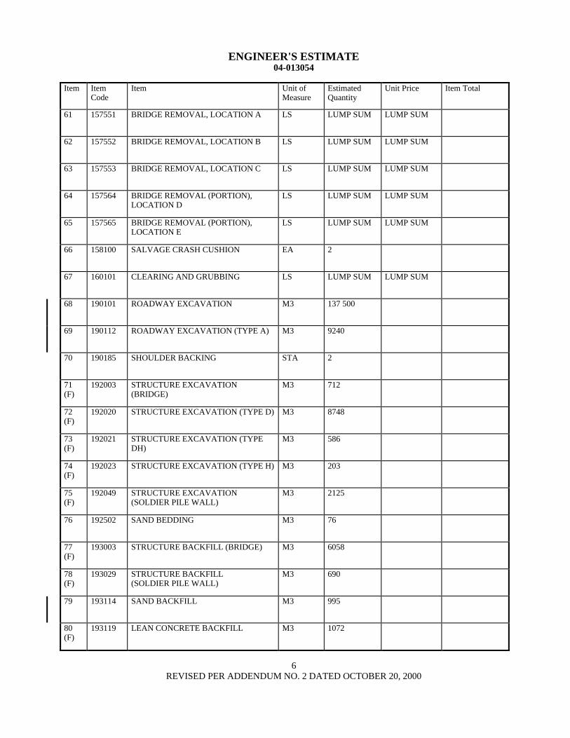
ENGINEERS ESTIMATE 04-013054
Item Item Code
Item Unit of Measure
Estimated Quantity
Unit Price Item Total
81 (F)
048329 CLASS 1 CONCRETE BACKFILL M3 1460
82 194001 DITCH EXCAVATION M3 7
83 (F)
197020 EARTH RETAINING STRUCTURE M2 1056
84 198007 IMPORTED MATERIAL (SHOULDER BACKING)
M3 27
85 019462 GEOGRID M2 19 800
86 (S)
200001 HIGHWAY PLANTING LS LUMP SUM LUMP SUM
87 200101 IMPORTED TOPSOIL M3 4560
88 203001 EROSION CONTROL (BLANKET) M2 78
89 (S)
203003 STRAW (EROSION CONTROL) TONN 11
90 (S)
203024 COMPOST (EROSION CONTROL) KG 2160
91 (S)
203014 FIBER (EROSION CONTROL) KG 920
92 (S)
203021 FIBER ROLLS M 4110
93 (S)
203045 PURE LIVE SEED (EROSION CONTROL)
KG 270
94 (S)
203056 COMMERCIAL FERTILIZER (EROSION CONTROL)
KG 330
95 (S)
203061 STABILIZING EMULSION (EROSION CONTROL)
KG 580
96 (S)
204099 PLANT ESTABLISHMENT WORK LS LUMP SUM LUMP SUM
97 (S)
208000 IRRIGATION SYSTEM LS LUMP SUM LUMP SUM
98 048330 NPS 15 SUPPLY LINE (BRIDGE) M 140
99 208039 NPS 4 SUPPLY LINE (BRIDGE) M 140
100 048331 MODIFY NPS 4 SUPPLY LINE (BRIDGE)
M 22
7 REVISED PER ADDENDUM NO 2 DATED OCTOBER 20 2000
ENGINEERS ESTIMATE 04-013054
Item Item Code
Item Unit of Measure
Estimated Quantity
Unit Price Item Total
101 208731 200 MM CORRUGATED HIGH DENSITY POLYETHYLENE PIPE CONDUIT
M 41
102 250401 CLASS 4 AGGREGATE SUBBASE M3 9290
103 260301 CLASS 3 AGGREGATE BASE M3 1390
104 280000 LEAN CONCRETE BASE M3 4970
105 290211 ASPHALT TREATED PERMEABLE BASE
M3 440
106 390095 REPLACE ASPHALT CONCRETE SURFACING
M3 23
107 390155 ASPHALT CONCRETE (TYPE A) TONN 17 070
108 390171 ASPHALT CONCRETE BASE (TYPE A)
TONN 1410
109 394002 PLACE ASPHALT CONCRETE (MISCELLANEOUS AREA)
M2 420
110 394040 PLACE ASPHALT CONCRETE DIKE (TYPE A)
M 1650
111 394048 PLACE ASPHALT CONCRETE DIKE (TYPE E)
M 360
112 394049 PLACE ASPHALT CONCRETE DIKE (TYPE F)
M 350
113 397001 ASPHALTIC EMULSION (PAINT BINDER)
TONN 190
114 401000 CONCRETE PAVEMENT M3 9610
115 048332 DRILLED HOLE (750 MM) M 655
116 048333 DRILLED HOLE (900 MM) M 3108
117 048334 DRILLED HOLE (1000 MM) M 325
118 490505 FURNISH STEEL PILING (HP 250 X 62)
M 312
119 (S)
490506 DRIVE STEEL PILE (HP 250 X 62) EA 21
120 490570 FURNISH STEEL PILING (HP 360 X 174)
M 3613
8 REVISED PER ADDENDUM NO 2 DATED OCTOBER 20 2000
ENGINEERS ESTIMATE 04-013054
Item Item Code
Item Unit of Measure
Estimated Quantity
Unit Price Item Total
121 (S)
490571 DRIVE STEEL PILE (HP 360 X 174) EA 120
122 (S)
490657 600 MM CAST-IN-DRILLED-HOLE CONCRETE PILING
M 5632
123 (S)
490658 750 MM CAST-IN-DRILLED-HOLE CONCRETE PILING
M 1890
124 (S)
490671 24 M CAST-IN-DRILLED-HOLE CONCRETE PILING
M 74
125 (F)
048335 STEEL SOLDIER PILE (W360 X 79) M 1000
126 (F)
048336 STEEL SOLDIER PILE (W360 X 101) M 4624
127 (F)
048337 STEEL SOLDIER PILE (W410 X 114) M 416
128 (F)
048338 STEEL SOLDIER PILE (W410 X 149) M 636
129 (F)
048339 STEEL SOLDIER PILE (W460 X 97) M 175
130 (F)
048340 STEEL SOLDIER PILE (W460 X 128) M 108
131 (F)
048341 STEEL SOLDIER PILE (W530 X 219) M 370
132 (F)
048342 STEEL SOLDIER PILE (W690 X 265) M 265
133 499036 FURNISH CAST-IN-STEEL-SHELL CONCRETE PILING (762 MM)
M 5075
134 (S)
499037 DRIVE CAST-IN-STEEL-SHELL CONCRETE PILE (762 MM)
EA 194
135 (S)
500001 PRESTRESSING CAST-IN-PLACE CONCRETE
LS LUMP SUM LUMP SUM
136 (S)
500050 TIEBACK ANCHOR EA 454
137 (F)
048343 STRUCTURAL CONCRETE FACING M3 485
138 (F)
048344 ARCHITECTURAL SURFACE TREATMENT
M2 502
139 (F)
510051 STRUCTURAL CONCRETE BRIDGE FOOTING
M3 3245
140 (F)
510053 STRUCTURAL CONCRETE BRIDGE M3 21 109
9 REVISED PER ADDENDUM NO 2 DATED OCTOBER 20 2000
ENGINEERS ESTIMATE 04-013054
Item Item Code
Item Unit of Measure
Estimated Quantity
Unit Price Item Total
141 (F)
510086 STRUCTURAL CONCRETE APPROACH SLAB (TYPE N)
M3 190
142 (F)
510502 MINOR CONCRETE (MINOR STRUCTURE)
M3 201
143 BLANK
144 (F)
048345 LIGHTWEIGHT CONCRETE (BRIDGE) M3 1729
145 (F)
511064 FRACTURED RIB TEXTURE M2 920
146 511106 DRILL AND BOND DOWEL M 70
147 (F)
513501 CONCRETE CLOSURE WALL M2 52
148 (S)
518050 PTFE BEARING EA 19
149 (S)
048346 PTFE BEARING (SPHERICAL) EA 48
150 (S)
519127 JOINT SEAL ASSEMBLY (MR 90 MM) M 8
151 (S)
519128 JOINT SEAL ASSEMBLY (MR 100 MM)
M 32
152 (S)
519129 JOINT SEAL ASSEMBLY (MR 101 MM - 160 MM)
M 20
153 (S)
519130 JOINT SEAL ASSEMBLY (MR 161 MM - 240 MM)
M 52
154 (S)
519132 JOINT SEAL ASSEMBLY (MR 321 MM - 400 MM)
M 62
155 (S-F)
520102 BAR REINFORCING STEEL (BRIDGE) KG 4 735 500
156 (S)
048347 WELDED HEADED BAR REINFORCEMENT
EA 47 025
157 (S-F)
520103 BAR REINFORCING STEEL (RETAINING WALL)
KG 87 400
158 (S-F)
520110 BAR REINFORCING STEEL (EPOXY COATED) (BRIDGE)
KG 388 000
159 (F)
530100 SHOTCRETE M3 152
160 (S-F)
550102 STRUCTURAL STEEL (BRIDGE) KG 60 080
10 REVISED PER ADDENDUM NO 2 DATED OCTOBER 20 2000
ENGINEERS ESTIMATE 04-013054
Item Item Code
Item Unit of Measure
Estimated Quantity
Unit Price Item Total
161 (S-F)
550203 FURNISH STRUCTURAL STEEL (BRIDGE)
KG 395 200
162 (S-F)
550204 ERECT STRUCTURAL STEEL (BRIDGE)
KG 395 200
163 (S-F)
048348 ISOLATION CASING KG 12 512
164 (S-F)
560218 FURNISH SIGN STRUCTURE (TRUSS) KG 35 435
165 (S-F)
560219 INSTALL SIGN STRUCTURE (TRUSS) KG 35 435
166 (S)
561009 920 MM CAST-IN-DRILLED-HOLE CONCRETE PILE (SIGN FOUNDATION)
M 44
167 562002 METAL (BARRIER MOUNTED SIGN) KG 160
168 562004 METAL (RAIL MOUNTED SIGN) KG 400
169 566011 ROADSIDE SIGN - ONE POST EA 13
170 566012 ROADSIDE SIGN - TWO POST EA 13
171 568001 INSTALL SIGN (STRAP AND SADDLE BRACKET METHOD)
EA 14
172 568007 INSTALL SIGN OVERLAY M2 28
173 568016 INSTALL SIGN PANEL ON EXISTING FRAME
M2 6
174 (F)
575004 TIMBER LAGGING M3 458
175 048349 CLEAN AND PAINT SOLDIER PILE LS LUMP SUM LUMP SUM
176 (S)
590115 CLEAN AND PAINT STRUCTURAL STEEL
LS LUMP SUM LUMP SUM
177 (S)
590135 SPOT BLAST CLEAN AND PAINT UNDERCOAT
M2 2543
178 (S)
048350 WORK AREA MONITORING (LOCATION A)
LS LUMP SUM LUMP SUM
179 (S)
048351 WORK AREA MONITORING (LOCATION B)
LS LUMP SUM LUMP SUM
180 620901 150 MM ALTERNATIVE PIPE CULVERT
M 08
11 REVISED PER ADDENDUM NO 2 DATED OCTOBER 20 2000
ENGINEERS ESTIMATE 04-013054
Item Item Code
Item Unit of Measure
Estimated Quantity
Unit Price Item Total
181 620904 300 MM ALTERNATIVE PIPE CULVERT
M 2
182 620909 450 MM ALTERNATIVE PIPE CULVERT
M 480
183 620913 600 MM ALTERNATIVE PIPE CULVERT
M 140
184 620924 900 MM ALTERNATIVE PIPE CULVERT
M 355
185 650069 450 MM REINFORCED CONCRETE PIPE
M 940
186 650075 600 MM REINFORCED CONCRETE PIPE
M 390
187 650079 900 MM REINFORCED CONCRETE PIPE
M 86
188 650084 1200 MM REINFORCED CONCRETE PIPE
M 110
189 664009 300 MM CORRUGATED STEEL PIPE (163 MM THICK)
M 34
190 664010 300 MM CORRUGATED STEEL PIPE (201 MM THICK)
M 17
191 664014 450 MM CORRUGATED STEEL PIPE (163 MM THICK)
M 39
192 681134 80 MM PLASTIC PIPE (EDGE DRAIN) M 370
193 682049 CLASS 3 PERMEABLE MATERIAL (BLANKET)
M3 7250
194 685067 200 MM ALTERNATIVE PIPE UNDERDRAIN
M 2970
195 019463 300 MM TRENCH DRAIN M 1890
196 019464 400 MM TRENCH DRAIN M 22
197 703542 300 MM WELDED STEEL PIPE (267 MM THICK)
M 33
198 705336 450 MM ALTERNATIVE FLARED END SECTION
EA 1
199 721009 ROCK SLOPE PROTECTION (FACING METHOD B)
M3 63
200 725001 SACKED CONCRETE SLOPE PROTECTION
M3 16
12 REVISED PER ADDENDUM NO 2 DATED OCTOBER 20 2000
ENGINEERS ESTIMATE 04-013054
Item Item Code
Item Unit of Measure
Estimated Quantity
Unit Price Item Total
201 729010 ROCK SLOPE PROTECTION FABRIC M2 21
202 731502 MINOR CONCRETE (MISCELLANEOUS CONSTRUCTION)
M3 600
203 (F)
731517 MINOR CONCRETE (GUTTER) M 528
204 (S-F)
750001 MISCELLANEOUS IRON AND STEEL KG 11 080
205 (S-F)
750501 MISCELLANEOUS METAL (BRIDGE) KG 54 430
206 (S-F)
750505 BRIDGE DECK DRAINAGE SYSTEM KG 36 160
207 (S-F)
800386 CHAIN LINK FENCE (TYPE CL-12 VINYL-CLAD)
M 300
208 (S)
800391 CHAIN LINK FENCE (TYPE CL-18) M 493
209 (S-F)
800392 CHAIN LINK FENCE (TYPE CL-18 VINYL-CLAD)
M 232
210 (S)
802592 24 M CHAIN LINK GATE (TYPE CL-18)
EA 1
211 (S)
019465 96 M CHAIN LINK GATE (TYPE CL-18)
EA 1
212 019466 48 M CHAIN GATE (TYPE CL-18) EA 1
213 820107 DELINEATOR (CLASS 1) EA 150
214 019467 CONCRETE BARRIER MARKER EA 156
215 820141 OBJECT MARKER (TYPE K-1) EA 1
216 019468 OBJECT MARKER (TYPE Q) EA 6
217 (S)
832002 METAL BEAM GUARD RAILING (STEEL POST)
M 720
218 (S-F)
833032 CHAIN LINK RAILING (TYPE 7) M 4
219 (F)
833125 CONCRETE BARRIER (TYPE 25) M 3267
220 (F)
833165 CONCRETE BARRIER (TYPE 27B MODIFIED)
M 120
13 REVISED PER ADDENDUM NO 2 DATED OCTOBER 20 2000
ENGINEERS ESTIMATE 04-013054
Item Item Code
Item Unit of Measure
Estimated Quantity
Unit Price Item Total
221 (F)
833187 CONCRETE BARRIER (TYPE 27 MODIFIED)
M 471
222 (F)
048352 CONCRETE BARRIER (TYPE 41) M 565
223 (S-F)
048353 BARRIER MOUNTED BRIDGE RAILING
M 591
224 (S-F)
048354 PEDESTRIAN RAILING M 584
225 (S)
839559 TERMINAL SYSTEM (TYPE ET) EA 1
226 (S)
839565 TERMINAL SYSTEM (TYPE SRT) EA 15
227 (S)
839591 CRASH CUSHION SAND FILLED EA 2
228 839701 CONCRETE BARRIER (TYPE 60) M 140
229 839702 CONCRETE BARRIER (TYPE 60A) M 1215
230 (F)
839704 CONCRETE BARRIER (TYPE 60D) M 300
231 (S)
840515 THERMOPLASTIC PAVEMENT MARKING
M2 325
232 (S)
840561 100 MM THERMOPLASTIC TRAFFIC STRIPE
M 14 550
233 (S)
840563 200 MM THERMOPLASTIC TRAFFIC STRIPE
M 1925
234 (S)
840571 100 MM THERMOPLASTIC TRAFFIC STRIPE (BROKEN 518 M - 214 M)
M 91
235 (S)
850101 PAVEMENT MARKER (NON-REFLECTIVE)
EA 3300
236 (S)
850111 PAVEMENT MARKER (RETROREFLECTIVE)
EA 1860
237 (S)
860201 SIGNAL AND LIGHTING LS LUMP SUM LUMP SUM
238 (S)
019469 LIGHTING STAGE CONSTRUCTION-LOCATION 1
LS LUMP SUM LUMP SUM
239 (S)
019470 LIGHTING STAGE CONSTRUCTION-LOCATION 2
LS LUMP SUM LUMP SUM
240 (S)
019471 LIGHTING AND SIGN ILLUMINATION AND TRAFFIC OPERATIONS SYSTEM STAGE CONSTRUCTION- LOCATION 3
LS LUMP SUM LUMP SUM
14 REVISED PER ADDENDUM NO 2 DATED OCTOBER 20 2000
ENGINEERS ESTIMATE 04-013054
Item Item Code
Item Unit of Measure
Estimated Quantity
Unit Price Item Total
241 (S)
019472 SIGNAL AND LIGHTING STAGE CONSTRUCTION-LOCATION 4
LS LUMP SUM LUMP SUM
242 (S)
860462 LIGHTING (LOCATION 2) LS LUMP SUM LUMP SUM
243 (S)
860551 LIGHTING AND SIGN ILLUMINATION (LOCATION 1)
LS LUMP SUM LUMP SUM
244 (S)
019473 CAMERA UNIT EA 1
245 (S)
019474 PANTILT UNIT EA 1
246 (S)
019475 CAMERA CONTROL UNIT EA 1
247 (S)
019476 VIDEO ENCODER UNIT EA 1
248 (S)
019477 INTEGRATED SERVICE DIGITAL NETWORK TERMINAL ADAPTER
EA 1
249 (S)
019478 CLUSTER CONTROLLER FOR MICROWAVE VEHICLE DETECTION SENSOR SYSTEM
EA 1
250 (S)
019479 ANALOG DATA STATION TERMINATION
EA 1
251 (S)
019480 TRAFFIC OPERATIONS SYSTEM (LOCATION-1)
LS LUMP SUM LUMP SUM
252 (S)
019481 TRAFFIC OPERATIONS SYSTEM (LOCATION-2)
LS LUMP SUM LUMP SUM
253 (S)
019482 TRAFFIC OPERATIONS SYSTEM (LOCATION-3)
LS LUMP SUM LUMP SUM
254 (S)
019483 CALLBOX SYSTEM LS LUMP SUM LUMP SUM
255 (S)
869072 SEISMIC MONITORING SYSTEM LS LUMP SUM LUMP SUM
256 (S)
048355 INSTALL SEISMIC MONITORING CASING
M 184
257 BLANK
258 020059 50 MM PERFORATED PLASTIC PIPE M 1571
259 020060 50 MM PLASTIC PIPE M 272
260 BLANK
15 REVISED PER ADDENDUM NO 2 DATED OCTOBER 20 2000
ENGINEERS ESTIMATE 04-013054
Item Item Code
Item Unit of Measure
Estimated Quantity
Unit Price Item Total
261 020131 REMOVE CHAIN LINK GATE EA 3
262 193001 STRUCTURE BACKFILL M3 22 600
263 020132 STRUCTURE BACKFILL (TYPE E)
M3 20 500
264 685062 150MM ALTERNATIVE PIPE UNDERDRAIN
M 230
265 999990 MOBILIZATION LS LUMP SUM LUMP SUM
15A ADDED PER ADDENDUM NO 2 DATED OCTOBER 20 2000
ENGINEERS ESTIMATE 04-013054
TOTAL BID (A) =
TOTAL BID (B) $ 3500000 X ____________________ =
(Cost Per Day) (Working Days Bid For Phase II Work) (Not To Exceed 610 Days)
BASIS FOR COMPARISON OF BIDS (A) + (B) =
Notes
1 TOTAL BID (A) is the grand total of the Item Totals in the Engineers Estimate
2 Working Days Bid is defined in the Special Provisions
16 REVISED PER ADDENDUM NO 2 DATED OCTOBER 20 2000
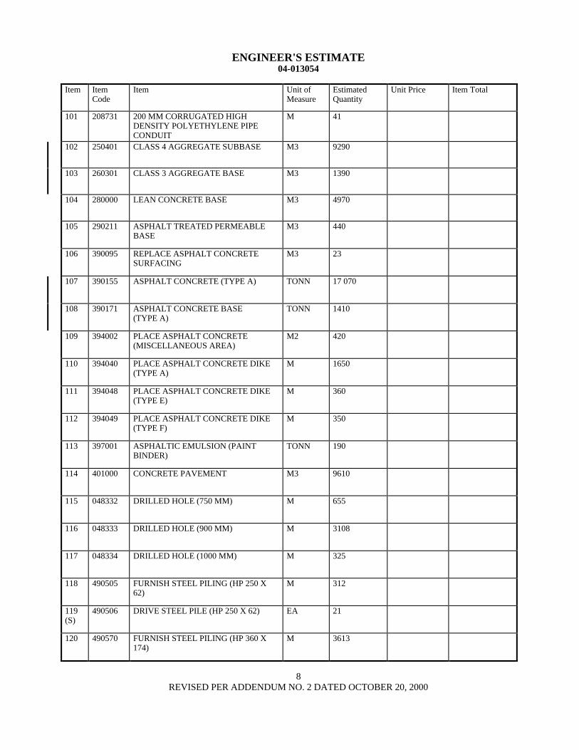
ENGINEERS ESTIMATE 04-013054
Item Item Code
Item Unit of Measure
Estimated Quantity
Unit Price Item Total
121 (S)
490571 DRIVE STEEL PILE (HP 360 X 174) EA 120
122 (S)
490657 600 MM CAST-IN-DRILLED-HOLE CONCRETE PILING
M 5632
123 (S)
490658 750 MM CAST-IN-DRILLED-HOLE CONCRETE PILING
M 1890
124 (S)
490671 24 M CAST-IN-DRILLED-HOLE CONCRETE PILING
M 74
125 (F)
048335 STEEL SOLDIER PILE (W360 X 79) M 1000
126 (F)
048336 STEEL SOLDIER PILE (W360 X 101) M 4624
127 (F)
048337 STEEL SOLDIER PILE (W410 X 114) M 416
128 (F)
048338 STEEL SOLDIER PILE (W410 X 149) M 636
129 (F)
048339 STEEL SOLDIER PILE (W460 X 97) M 175
130 (F)
048340 STEEL SOLDIER PILE (W460 X 128) M 108
131 (F)
048341 STEEL SOLDIER PILE (W530 X 219) M 370
132 (F)
048342 STEEL SOLDIER PILE (W690 X 265) M 265
133 499036 FURNISH CAST-IN-STEEL-SHELL CONCRETE PILING (762 MM)
M 5075
134 (S)
499037 DRIVE CAST-IN-STEEL-SHELL CONCRETE PILE (762 MM)
EA 194
135 (S)
500001 PRESTRESSING CAST-IN-PLACE CONCRETE
LS LUMP SUM LUMP SUM
136 (S)
500050 TIEBACK ANCHOR EA 454
137 (F)
048343 STRUCTURAL CONCRETE FACING M3 485
138 (F)
048344 ARCHITECTURAL SURFACE TREATMENT
M2 502
139 (F)
510051 STRUCTURAL CONCRETE BRIDGE FOOTING
M3 3245
140 (F)
510053 STRUCTURAL CONCRETE BRIDGE M3 21 109
9 REVISED PER ADDENDUM NO 2 DATED OCTOBER 20 2000
ENGINEERS ESTIMATE 04-013054
Item Item Code
Item Unit of Measure
Estimated Quantity
Unit Price Item Total
141 (F)
510086 STRUCTURAL CONCRETE APPROACH SLAB (TYPE N)
M3 190
142 (F)
510502 MINOR CONCRETE (MINOR STRUCTURE)
M3 201
143 BLANK
144 (F)
048345 LIGHTWEIGHT CONCRETE (BRIDGE) M3 1729
145 (F)
511064 FRACTURED RIB TEXTURE M2 920
146 511106 DRILL AND BOND DOWEL M 70
147 (F)
513501 CONCRETE CLOSURE WALL M2 52
148 (S)
518050 PTFE BEARING EA 19
149 (S)
048346 PTFE BEARING (SPHERICAL) EA 48
150 (S)
519127 JOINT SEAL ASSEMBLY (MR 90 MM) M 8
151 (S)
519128 JOINT SEAL ASSEMBLY (MR 100 MM)
M 32
152 (S)
519129 JOINT SEAL ASSEMBLY (MR 101 MM - 160 MM)
M 20
153 (S)
519130 JOINT SEAL ASSEMBLY (MR 161 MM - 240 MM)
M 52
154 (S)
519132 JOINT SEAL ASSEMBLY (MR 321 MM - 400 MM)
M 62
155 (S-F)
520102 BAR REINFORCING STEEL (BRIDGE) KG 4 735 500
156 (S)
048347 WELDED HEADED BAR REINFORCEMENT
EA 47 025
157 (S-F)
520103 BAR REINFORCING STEEL (RETAINING WALL)
KG 87 400
158 (S-F)
520110 BAR REINFORCING STEEL (EPOXY COATED) (BRIDGE)
KG 388 000
159 (F)
530100 SHOTCRETE M3 152
160 (S-F)
550102 STRUCTURAL STEEL (BRIDGE) KG 60 080
10 REVISED PER ADDENDUM NO 2 DATED OCTOBER 20 2000
ENGINEERS ESTIMATE 04-013054
Item Item Code
Item Unit of Measure
Estimated Quantity
Unit Price Item Total
161 (S-F)
550203 FURNISH STRUCTURAL STEEL (BRIDGE)
KG 395 200
162 (S-F)
550204 ERECT STRUCTURAL STEEL (BRIDGE)
KG 395 200
163 (S-F)
048348 ISOLATION CASING KG 12 512
164 (S-F)
560218 FURNISH SIGN STRUCTURE (TRUSS) KG 35 435
165 (S-F)
560219 INSTALL SIGN STRUCTURE (TRUSS) KG 35 435
166 (S)
561009 920 MM CAST-IN-DRILLED-HOLE CONCRETE PILE (SIGN FOUNDATION)
M 44
167 562002 METAL (BARRIER MOUNTED SIGN) KG 160
168 562004 METAL (RAIL MOUNTED SIGN) KG 400
169 566011 ROADSIDE SIGN - ONE POST EA 13
170 566012 ROADSIDE SIGN - TWO POST EA 13
171 568001 INSTALL SIGN (STRAP AND SADDLE BRACKET METHOD)
EA 14
172 568007 INSTALL SIGN OVERLAY M2 28
173 568016 INSTALL SIGN PANEL ON EXISTING FRAME
M2 6
174 (F)
575004 TIMBER LAGGING M3 458
175 048349 CLEAN AND PAINT SOLDIER PILE LS LUMP SUM LUMP SUM
176 (S)
590115 CLEAN AND PAINT STRUCTURAL STEEL
LS LUMP SUM LUMP SUM
177 (S)
590135 SPOT BLAST CLEAN AND PAINT UNDERCOAT
M2 2543
178 (S)
048350 WORK AREA MONITORING (LOCATION A)
LS LUMP SUM LUMP SUM
179 (S)
048351 WORK AREA MONITORING (LOCATION B)
LS LUMP SUM LUMP SUM
180 620901 150 MM ALTERNATIVE PIPE CULVERT
M 08
11 REVISED PER ADDENDUM NO 2 DATED OCTOBER 20 2000
ENGINEERS ESTIMATE 04-013054
Item Item Code
Item Unit of Measure
Estimated Quantity
Unit Price Item Total
181 620904 300 MM ALTERNATIVE PIPE CULVERT
M 2
182 620909 450 MM ALTERNATIVE PIPE CULVERT
M 480
183 620913 600 MM ALTERNATIVE PIPE CULVERT
M 140
184 620924 900 MM ALTERNATIVE PIPE CULVERT
M 355
185 650069 450 MM REINFORCED CONCRETE PIPE
M 940
186 650075 600 MM REINFORCED CONCRETE PIPE
M 390
187 650079 900 MM REINFORCED CONCRETE PIPE
M 86
188 650084 1200 MM REINFORCED CONCRETE PIPE
M 110
189 664009 300 MM CORRUGATED STEEL PIPE (163 MM THICK)
M 34
190 664010 300 MM CORRUGATED STEEL PIPE (201 MM THICK)
M 17
191 664014 450 MM CORRUGATED STEEL PIPE (163 MM THICK)
M 39
192 681134 80 MM PLASTIC PIPE (EDGE DRAIN) M 370
193 682049 CLASS 3 PERMEABLE MATERIAL (BLANKET)
M3 7250
194 685067 200 MM ALTERNATIVE PIPE UNDERDRAIN
M 2970
195 019463 300 MM TRENCH DRAIN M 1890
196 019464 400 MM TRENCH DRAIN M 22
197 703542 300 MM WELDED STEEL PIPE (267 MM THICK)
M 33
198 705336 450 MM ALTERNATIVE FLARED END SECTION
EA 1
199 721009 ROCK SLOPE PROTECTION (FACING METHOD B)
M3 63
200 725001 SACKED CONCRETE SLOPE PROTECTION
M3 16
12 REVISED PER ADDENDUM NO 2 DATED OCTOBER 20 2000
ENGINEERS ESTIMATE 04-013054
Item Item Code
Item Unit of Measure
Estimated Quantity
Unit Price Item Total
201 729010 ROCK SLOPE PROTECTION FABRIC M2 21
202 731502 MINOR CONCRETE (MISCELLANEOUS CONSTRUCTION)
M3 600
203 (F)
731517 MINOR CONCRETE (GUTTER) M 528
204 (S-F)
750001 MISCELLANEOUS IRON AND STEEL KG 11 080
205 (S-F)
750501 MISCELLANEOUS METAL (BRIDGE) KG 54 430
206 (S-F)
750505 BRIDGE DECK DRAINAGE SYSTEM KG 36 160
207 (S-F)
800386 CHAIN LINK FENCE (TYPE CL-12 VINYL-CLAD)
M 300
208 (S)
800391 CHAIN LINK FENCE (TYPE CL-18) M 493
209 (S-F)
800392 CHAIN LINK FENCE (TYPE CL-18 VINYL-CLAD)
M 232
210 (S)
802592 24 M CHAIN LINK GATE (TYPE CL-18)
EA 1
211 (S)
019465 96 M CHAIN LINK GATE (TYPE CL-18)
EA 1
212 019466 48 M CHAIN GATE (TYPE CL-18) EA 1
213 820107 DELINEATOR (CLASS 1) EA 150
214 019467 CONCRETE BARRIER MARKER EA 156
215 820141 OBJECT MARKER (TYPE K-1) EA 1
216 019468 OBJECT MARKER (TYPE Q) EA 6
217 (S)
832002 METAL BEAM GUARD RAILING (STEEL POST)
M 720
218 (S-F)
833032 CHAIN LINK RAILING (TYPE 7) M 4
219 (F)
833125 CONCRETE BARRIER (TYPE 25) M 3267
220 (F)
833165 CONCRETE BARRIER (TYPE 27B MODIFIED)
M 120
13 REVISED PER ADDENDUM NO 2 DATED OCTOBER 20 2000
ENGINEERS ESTIMATE 04-013054
Item Item Code
Item Unit of Measure
Estimated Quantity
Unit Price Item Total
221 (F)
833187 CONCRETE BARRIER (TYPE 27 MODIFIED)
M 471
222 (F)
048352 CONCRETE BARRIER (TYPE 41) M 565
223 (S-F)
048353 BARRIER MOUNTED BRIDGE RAILING
M 591
224 (S-F)
048354 PEDESTRIAN RAILING M 584
225 (S)
839559 TERMINAL SYSTEM (TYPE ET) EA 1
226 (S)
839565 TERMINAL SYSTEM (TYPE SRT) EA 15
227 (S)
839591 CRASH CUSHION SAND FILLED EA 2
228 839701 CONCRETE BARRIER (TYPE 60) M 140
229 839702 CONCRETE BARRIER (TYPE 60A) M 1215
230 (F)
839704 CONCRETE BARRIER (TYPE 60D) M 300
231 (S)
840515 THERMOPLASTIC PAVEMENT MARKING
M2 325
232 (S)
840561 100 MM THERMOPLASTIC TRAFFIC STRIPE
M 14 550
233 (S)
840563 200 MM THERMOPLASTIC TRAFFIC STRIPE
M 1925
234 (S)
840571 100 MM THERMOPLASTIC TRAFFIC STRIPE (BROKEN 518 M - 214 M)
M 91
235 (S)
850101 PAVEMENT MARKER (NON-REFLECTIVE)
EA 3300
236 (S)
850111 PAVEMENT MARKER (RETROREFLECTIVE)
EA 1860
237 (S)
860201 SIGNAL AND LIGHTING LS LUMP SUM LUMP SUM
238 (S)
019469 LIGHTING STAGE CONSTRUCTION-LOCATION 1
LS LUMP SUM LUMP SUM
239 (S)
019470 LIGHTING STAGE CONSTRUCTION-LOCATION 2
LS LUMP SUM LUMP SUM
240 (S)
019471 LIGHTING AND SIGN ILLUMINATION AND TRAFFIC OPERATIONS SYSTEM STAGE CONSTRUCTION- LOCATION 3
LS LUMP SUM LUMP SUM
14 REVISED PER ADDENDUM NO 2 DATED OCTOBER 20 2000
ENGINEERS ESTIMATE 04-013054
Item Item Code
Item Unit of Measure
Estimated Quantity
Unit Price Item Total
241 (S)
019472 SIGNAL AND LIGHTING STAGE CONSTRUCTION-LOCATION 4
LS LUMP SUM LUMP SUM
242 (S)
860462 LIGHTING (LOCATION 2) LS LUMP SUM LUMP SUM
243 (S)
860551 LIGHTING AND SIGN ILLUMINATION (LOCATION 1)
LS LUMP SUM LUMP SUM
244 (S)
019473 CAMERA UNIT EA 1
245 (S)
019474 PANTILT UNIT EA 1
246 (S)
019475 CAMERA CONTROL UNIT EA 1
247 (S)
019476 VIDEO ENCODER UNIT EA 1
248 (S)
019477 INTEGRATED SERVICE DIGITAL NETWORK TERMINAL ADAPTER
EA 1
249 (S)
019478 CLUSTER CONTROLLER FOR MICROWAVE VEHICLE DETECTION SENSOR SYSTEM
EA 1
250 (S)
019479 ANALOG DATA STATION TERMINATION
EA 1
251 (S)
019480 TRAFFIC OPERATIONS SYSTEM (LOCATION-1)
LS LUMP SUM LUMP SUM
252 (S)
019481 TRAFFIC OPERATIONS SYSTEM (LOCATION-2)
LS LUMP SUM LUMP SUM
253 (S)
019482 TRAFFIC OPERATIONS SYSTEM (LOCATION-3)
LS LUMP SUM LUMP SUM
254 (S)
019483 CALLBOX SYSTEM LS LUMP SUM LUMP SUM
255 (S)
869072 SEISMIC MONITORING SYSTEM LS LUMP SUM LUMP SUM
256 (S)
048355 INSTALL SEISMIC MONITORING CASING
M 184
257 BLANK
258 020059 50 MM PERFORATED PLASTIC PIPE M 1571
259 020060 50 MM PLASTIC PIPE M 272
260 BLANK
15 REVISED PER ADDENDUM NO 2 DATED OCTOBER 20 2000
ENGINEERS ESTIMATE 04-013054
Item Item Code
Item Unit of Measure
Estimated Quantity
Unit Price Item Total
261 020131 REMOVE CHAIN LINK GATE EA 3
262 193001 STRUCTURE BACKFILL M3 22 600
263 020132 STRUCTURE BACKFILL (TYPE E)
M3 20 500
264 685062 150MM ALTERNATIVE PIPE UNDERDRAIN
M 230
265 999990 MOBILIZATION LS LUMP SUM LUMP SUM
15A ADDED PER ADDENDUM NO 2 DATED OCTOBER 20 2000
ENGINEERS ESTIMATE 04-013054
TOTAL BID (A) =
TOTAL BID (B) $ 3500000 X ____________________ =
(Cost Per Day) (Working Days Bid For Phase II Work) (Not To Exceed 610 Days)
BASIS FOR COMPARISON OF BIDS (A) + (B) =
Notes
1 TOTAL BID (A) is the grand total of the Item Totals in the Engineers Estimate
2 Working Days Bid is defined in the Special Provisions
16 REVISED PER ADDENDUM NO 2 DATED OCTOBER 20 2000
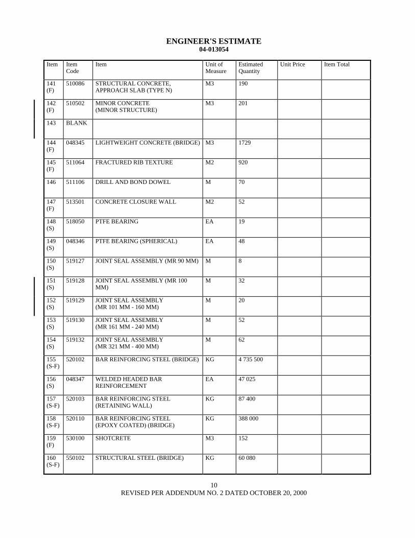
ENGINEERS ESTIMATE 04-013054
Item Item Code
Item Unit of Measure
Estimated Quantity
Unit Price Item Total
261 020131 REMOVE CHAIN LINK GATE EA 3
262 193001 STRUCTURE BACKFILL M3 22 600
263 020132 STRUCTURE BACKFILL (TYPE E)
M3 20 500
264 685062 150MM ALTERNATIVE PIPE UNDERDRAIN
M 230
265 999990 MOBILIZATION LS LUMP SUM LUMP SUM
15A ADDED PER ADDENDUM NO 2 DATED OCTOBER 20 2000
ENGINEERS ESTIMATE 04-013054
TOTAL BID (A) =
TOTAL BID (B) $ 3500000 X ____________________ =
(Cost Per Day) (Working Days Bid For Phase II Work) (Not To Exceed 610 Days)
BASIS FOR COMPARISON OF BIDS (A) + (B) =
Notes
1 TOTAL BID (A) is the grand total of the Item Totals in the Engineers Estimate
2 Working Days Bid is defined in the Special Provisions
16 REVISED PER ADDENDUM NO 2 DATED OCTOBER 20 2000

ENGINEERS ESTIMATE 04-013054
TOTAL BID (A) =
TOTAL BID (B) $ 3500000 X ____________________ =
(Cost Per Day) (Working Days Bid For Phase II Work) (Not To Exceed 610 Days)
BASIS FOR COMPARISON OF BIDS (A) + (B) =
Notes
1 TOTAL BID (A) is the grand total of the Item Totals in the Engineers Estimate
2 Working Days Bid is defined in the Special Provisions
16 REVISED PER ADDENDUM NO 2 DATED OCTOBER 20 2000