Embed Size (px)
Citation preview

Department of Mechanical Engineering 1
Meshing of 2-D Cross SectionMesh Tool Comparison
Group: Graden Hardy, Patrick LewisDate: 22 April 2009
ME 501 – Design of Mechanical Structures

Outline
Department of Mechanical Engineering 2
Problem Description Model Description Results
Free Mesh – Default Free Mesh – Smart Size Free Mesh – Size
Control:Global Free Mesh – Q-Morph
Mesher Mapped Mesh –
Regions Discussion
Automatic Vs. Mapped “Mesh Tool” “Mesher Opts”

Problem Description
Develop a cross section that would require the use of advanced mesh generation tools
Provide a comparison of the different mesh tools that are available Visually inspect the resulting element shapes
and sizes
Department of Mechanical Engineering 3

Model Description
Department of Mechanical Engineering 4
Geometry Solid CAD model
created CAD Drawing
developed for modeling in ANSYS
Element Type 2-D Plane Stress
Element Plane 82 (Solid
Quad 8node – 82)

Results
Meshing Tools: Free Mesh Mapped Mesh
Tool Options Explored Free Mesh
Default Smart Size Size Control:Global Q-Morph Mesher
Mapped Mesh Regions
Department of Mechanical Engineering 5

Free Mesh – Default
Tool Description: No constraints on element
patterns No constraints on element
shapes Capable of meshing irregular
shapes Element Plots:
Inability to control the element generation results in badly shaped elements
Meshing Error – Element Checker Angle between two adjoining
sides of an element can be no greater than 165°
For highlighted element the angle is 167.3°
Department of Mechanical Engineering 6

Free Mesh – Smart Size
Tool Description: Creates initial element sizes for free meshing
operations Better chance of creating reasonably shaped
elements Algorithm computes an estimated element edge
length for all lines in the area/volume being meshed Edge lengths are further refined to account for
curvature and proximity of surrounding features in the geometry
User must specify a mesh size level 1 (fine mesh) 10 (coarse mesh)
Department of Mechanical Engineering 7

Free Mesh – Smart Size Cont.
Free Mesh Element Plot w/Smart Size Level 4
Department of Mechanical Engineering 8

Free Mesh – Smart Size Cont.
Free Mesh Element Plot w/Smart Size Level 5
Department of Mechanical Engineering 9

Free Mesh – Size Control:Global
Tool Description: Mandates the size of
the elements to a default size set by the user
Requires knowledge and experimentation by the user to come to a suitable final element size
Element Plot: Provided a good mesh
w/no triangular elements Created several
transition elementsDepartment of Mechanical
Engineering 10

Free Mesh – Q-Morph Mesher
Tool Description: This mesher generally provides higher
quality quadrilateral elements than the alternative and is very effective with boundary sensitive geometries Meshing options must be carefully adjusted to
eliminate triangular elements Smart Size feature must be enabled
Global element size provision also provides a better mesh
Department of Mechanical Engineering 11

Free Mesh – Q-Morph Mesher Cont.
Department of Mechanical Engineering 12
Preprocessor Meshing Mesher Opts Triangle Mesher Alternate Quad Mesher MainSplit poor quality quads Off

Free Mesh – Q-Morph Mesher Cont.
Department of Mechanical Engineering 13
Video

Free Mesh – Q-Morph Mesher Cont.
Department of Mechanical Engineering 14
Element Plot: Provides a
decent mesh No triangular
elements Few oddly
shaped transition elements
Reasonable Pattern

Mapped Mesh – Regions
Tool Description: Constraints placed on element patterns and
shapes Only works with basic geometries
Irregular geometries must be broken down into basic regular regions
User has the option of choosing between quadrilateral or triangular elements
Department of Mechanical Engineering 15

Mapped Mesh – Regions Cont.
Video
Department of Mechanical Engineering 16
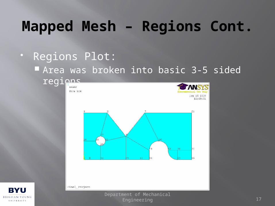
Mapped Mesh – Regions Cont.
Regions Plot: Area was broken into basic 3-5 sided regions
Department of Mechanical Engineering 17
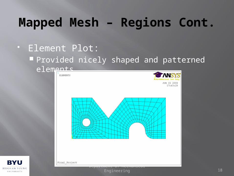
Mapped Mesh – Regions Cont.
Element Plot: Provided nicely shaped and patterned
elements
Department of Mechanical Engineering 18

Discussion
Automatic Vs. Mapped Meshing Automatic meshing functions have good
capabilities for meshing difficult geometries, but are limited in their abilities to provide uniform element shapes and patterns.
Mapped meshing tools, although tedious in use, are more powerful and controllable meshing tools
Department of Mechanical Engineering 19

Discussion Cont.
“Mesh Tool” Most efficient tool available for
rapid mesh creation/control Toolbar combines most of the
other mesh tool menus to allow the user to quickly navigate between different mesh tool settings and options.
This tool bar is activated by selecting: Preprocessor Meshing
Mesh ToolDepartment of Mechanical
Engineering 20

Discussion Cont.
“Mesher Opts” Powerful tool found
within the meshing menu
Toolbar allows for more advanced control of the meshing functions
This tool bar is activated by selecting: Preprocessor
Meshing Mesher Opts
Department of Mechanical Engineering 21

Questions?
Department of Mechanical Engineering 22