Embed Size (px)
Citation preview

Defense Information Systems AgencyCenter for Standards
DEPARTMENT OF DEFENSETECHNICAL ARCHITECTURE FRAMEWORK
FORINFORMATION MANAGEMENT
Volume 4:DoD Standards-Based Architecture
Planning Guide
Version 3.0
30 April 1996

Volume 4DoD Standards-Based Architecture Version 3.0Planning Guide ii 30 April 1996
This publication © U.S. Department of Defense.
Given the dynamic nature of the DoD environment,this document may contain terminology, diagrams,or policy discussions that are inconsistent withemerging DoD terminology, diagrams, or policydiscussions. This document will be updated on aregular basis to incorporate necessary changes.

Volume 4DoD Standards-Based Architecture Version 3.0Planning Guide iii 30 April 1996
FOREWORD:ABOUT THIS DOCUMENT
This edition of the Technical Architecture Framework for Information Management(TAFIM) replaces Version 2.0, dated 30 June 1994. Version 3.0 comprises eightvolumes, as listed on the following configuration management page.
TAFIM HARMONIZATION AND ALIGNMENT
This TAFIM version is the result of a review and comment coordination period thatbegan with the release of the 30 September 1995 Version 3.0 Draft. During thiscoordination period, a number of extremely significant activities were initiated byDoD. As a result, the version of the TAFIM that was valid at the beginning of thecoordination period is now “out of step” with the direction and preliminary outcomesof these DoD activities. Work on a complete TAFIM update is underway to reflect thepolicy, guidance, and recommendations coming from theses activities as they nearcompletion. Each TAFIM volume will be released as it is updated. Specifically, thenext TAFIM release will fully reflect decisions stemming from the following:
• The DoD 5000 Series of acquisition policy and procedure documents
• The Joint Technical Architecture (JTA), currently a preliminary draft documentunder review.
• The C4ISR Integrated Task Force (ITF) recommendations on Operational,Systems, and Technical architectures.
SUMMARY OF MAJOR CHANGES AND EXPECTED UPDATES
This document, Volume 4 of the TAFIM, contains no substantive changes fromVolume 4 of Version 2.0. Minor modifications have been made to acknowledge theevolving policies noted above. Substantive revisions to reflect these policy changesfully will be made in the next edition.
A NOTE ON VERSION NUMBERING
A version numbering scheme approved by the Architecture Methodology WorkingGroup (AMWG) will control the version numbers applied to all future editions ofTAFIM volumes. Version numbers will be applied and incremented as follows:
• This edition of the TAFIM is the official Version 3.0.

Volume 4DoD Standards-Based Architecture Version 3.0Planning Guide iv 30 April 1996
• From this point forward, single volumes will be updated and republished asneeded. The second digit in the version number will be incremented each time(e.g., Volume 7 Version 3.1). The new version number will be applied only to thevolume(s) that are updated at that time. There is no limit to the number of timesthe second digit can be changed to account for new editions of particular volumes.
• On an infrequent basis (e.g., every two years or more), the entire TAFIM set willbe republished at once. Only when all volumes are released simultaneously willthe first digit in the version number be changed. The next complete version will bedesignated Version 4.0.
• TAFIM volumes bearing a two-digit version number (e.g., Version 3.0, 3.1, etc.)without the DRAFT designation are final, official versions of the TAFIM. Onlythe TAFIM program manager can change the two-digit version number on avolume.
• A third digit can be added to the version number as needed to control workingdrafts, proposed volumes, internal review drafts, and other unofficial releases. Thesponsoring organization can append and change this digit as desired.
Certain TAFIM volumes developed for purposes outside the TAFIM may appearunder a different title and with a different version number from those specified in theconfiguration management page. These editions are not official releases of TAFIMvolumes.
DISTRIBUTION
Version 3.0 is available for download from the DISA Information TechnologyStandards Information (ITSI) bulletin board system (BBS). Users are welcome to addthe TAFIM files to individual organizations’ BBSs or file servers to facilitate wideravailability.
This final release of Version 3.0 will be made available on the World Wide Web(WWW) shortly after hard-copy publication. The Defense Information SystemsAgency (DISA) is also investigating other electronic distribution approaches tofacilitate access to the TAFIM and to enhance its usability.
Volume 4DoD Standards-Based Architecture Version 3.0Planning Guide v 30 April 1996
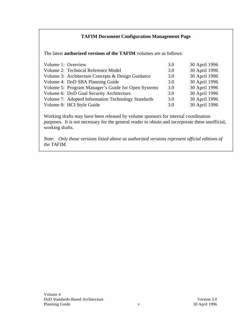
TAFIM Document Configuration Management Page
The latest authorized versions of the TAFIM volumes are as follows:
Volume 1: Overview 3.0 30 April 1996Volume 2: Technical Reference Model 3.0 30 April 1996Volume 3: Architecture Concepts & Design Guidance 3.0 30 April 1996Volume 4: DoD SBA Planning Guide 3.0 30 April 1996Volume 5: Program Manager’s Guide for Open Systems 3.0 30 April 1996Volume 6: DoD Goal Security Architecture 3.0 30 April 1996Volume 7: Adopted Information Technology Standards 3.0 30 April 1996Volume 8: HCI Style Guide 3.0 30 April 1996
Working drafts may have been released by volume sponsors for internal coordinationpurposes. It is not necessary for the general reader to obtain and incorporate these unofficial,working drafts.
Note: Only those versions listed above as authorized versions represent official editions ofthe TAFIM.

Volume 4DoD Standards-Based Architecture Version 3.0Planning Guide vi 30 April 1996
This page intentionally left blank.
Volume 4DoD Standards-Based Architecture Version 3.0Planning Guide vii 30 April 1996
Preface
A key element of the United States (U.S.) Department ofDefense’S (DoD) Corporate Information Management(CIM) initiatives for the 1990s is the implementation of acomputing and communications infrastructure that willsupport portability, scalability, and interoperability ofapplications.
Deputy Secretary of Defense William J. Perry’s policymemorandum of 13 October 1993 entitled “AcceleratedImplementation of Migration Systems, Data Standards, andProcess Improvement” reaffirms CIM principles and callsfor all DoD components to begin migration from legacy totarget systems in such a way “that migrate the systemtoward an open system environment and a standards-basedarchitecture defined by the DoD Technical ArchitectureFramework for Information Management” (TAFIM).
In support of this goal, the DoD Standards-BasedArchitecture Planning Guide (the SBA Guide) hasbecome Volume 4 of the TAFIM, which defines a commonframework and profile of standards for the computing andcommunications infrastructure. The methodologyprescribed in the SBA Guide provides a way of mappingthe technology architecture, which is the primary focus ofVolumes 1, 2, and 3 of TAFIM, to the three other views ofan integrated architecture: work, data or information, andapplications.
This version of the SBA Guide is an update of an earlierversion that was written from October 1991 through April1992 under contract #DCA100-91-C-0166. It presents aprocess for developing a standards-based architecturewithin the Department of Defense. At the time of thisupdate, two major architecture engagements have beencompleted based on the use of the planning approachdescribed in the earlier version of the SBA Guide. Thegoal of the updated SBA Guide is to incorporaterecommended changes that effectively echo the lessonslearned in the course of these two engagements.

Volume 4DoD Standards-Based Architecture Version 3.0Planning Guide viii 30 April 1996
The first major implementations of the SBA Guide wereintended to test the methodology in a “small” enterprise(Office of the Secretary of Defense, Office AutomationStandards-Based Architecture) and in a large-scaleenterprise implementation (Standards-Based Architecturefor the U.S. Marine Corps). The documents created as aresult of these initiatives currently constitute the bestreference source for the expected output from such aneffort.
The planning process itself specifically addresses theInformation Technology Policy Board (ITPB) Task 91-01policy proposal approved 10 April 1991, which states:
Develop a DoD standards-based open systems informationsystems architecture development methodology and establish aDoD implementation strategy.
The earlier version of the document was based on DMRGroup, Inc.’s Standards-Based Architectures, Vol. IV inthe STRATEGIES FOR OPEN SYSTEMS research program.This document, and its underlying architecturedevelopment process, was unique in its:
• New approach to gaining functional managementunderstanding of, support for, and involvement in theinformation systems architecture process
• Explicit determination of broad organizationalinformation systems architecture principles
• Explicit approach to creating an architecture based onstandards
• Express design to produce “vendor neutral”architectures
• Proven application across a wide range oforganizational types
• Immediate availability.
The process described herein is specifically designed sothat all target architectures derived through its use meetsstandards and incorporates the generalized guidance onopen systems environments (OSE) found in NationalInstitute of Standards and Technology (NIST) SpecialPublication 500-187, “Applications Portability Profile

Volume 4DoD Standards-Based Architecture Version 3.0Planning Guide ix 30 April 1996
(APP): The U.S. Government’s Open SystemsEnvironment Profile OSE/1 Version 2.0.”
Corporate Information Management practices and policiesare still evolving. As they do, this SBA Guide will alsorequire changes in its diagrammatic representations,terminology, and policy discussions.

Volume 4DoD Standards-Based Architecture Version 3.0Planning Guide x 30 April 1996
This page intentionally left blank.

Volume 4DoD Standards-Based Architecture Version 3.0Planning Guide xi 30 April 1996
An Executive Summary
This document was developed to assist users in the UnitedStates (U.S.) Department of Defense (DoD) in planningtechnology architectures based on standards-basedplatforms. It can be used within a functional unit ordepartment within the DoD (e.g., the Marine Corps). Theapproach may also be usefully applied at a lower, or sub-department, level to provide a more detailed view of thearchitecture.
Target audience Process facilitators constitute the primary audience ofinterest for whom this document was created. Experiencetells us that this planning process is most successful when itis led by someone who can bring an impartial view to bearon the consensus-building process that is central to thesuccess of the effort. An impartial and professionalfacilitator, experienced in the standards-based architecture(SBA) process, is essential in getting the process off theground. The facilitator will keep the process on track whenlocal, political, or technical perspectives threaten to getthings moving in the wrong direction or risk derailing theprocess. This is said in recognition of the fact that many ofthose asked to participate in the process are likely to bringwith them parochial views or hidden agendas that mightnot allow them to work effectively toward the commongoal of developing a mission-specific architecture. Thebest way to address these issues is through reliance on afacilitator who can identify stumbling blocks and move theteam around or over them.
The facilitator will have experience in facilitatingworkshop sessions with key knowledge workers to elicitrequired architectural content. The facilitator will alsopossess the ability to tailor the basic methodology asneeded to satisfy the unique demands of the enterprisebeing modeled. Thus, for the facilitator, this SBA Guidebecomes a sourcebook for customizing the specificmethodology to meet the specific goals of the organizationinvolved.

Volume 4DoD Standards-Based Architecture Version 3.0Planning Guide xii 30 April 1996
Other audiences will also be interested in this document. Itcan be used as a marketing tool to expose prospectiveparticipants or sponsors to the process and educate themabout what the SBA planning process can achieve. It isalso useful to those involved in the process to help themunderstand the importance of each step they are involved inand how one step serves as a basis for work to be done insuccessive steps of the process.
The SBA Guide can be used to “hand hold” those involvedwho may occasionally feel lost or overwhelmed by the taskin which they are involved.
This document is not a detailed methodology describing allattributes of information modeling, applicationdevelopment, security architecture, or detailed technicalimplementation project planning, nor does it describe themethodology by which “business process redesign” isaccomplished.
While this document discusses such subjects, it is notintended to provide the reader with a detailedunderstanding of those methodologies and techniques.Furthermore, it was not designed to develop a singlemonolithic DoD architecture for a single computer andcommunications solution that will fit all users across theDefense community.
Volume 4 of TAFIM The SBA methodology that is described in this guide isbased on four views of an integrated architecture: workorganization, information, applications, and technology.Volumes 1, 2, and 3 of the Technical Architecture forInformation Management (TAFIM) focus primarily on thetechnology architecture. The SBA methodology, whichconstitutes Volume 4 of the TAFIM, provides a way ofmapping the three other views (work, information, andapplications) to the technology architecture.
The SBA planning process is an especially important partof the TAFIM because it fleshes out the work, information,and application views of the architecture. It provides amechanism for translating the functional, or business,needs of the enterprise into the information technology(IT)-based solutions that ultimately flow fromimplementation of the entire TAFIM process.

Volume 4DoD Standards-Based Architecture Version 3.0Planning Guide xiii 30 April 1996
The planning process helps align IT with the businessneeds of the organization. The DoD Standards-BasedArchitecture Planning Guide describes how the overallprocess of planning for, and implementing, a standards-based architecture is conducted, highlighting some keyconsiderations in the overall effort. Because of the velocityof change in technology, which seems to be increasing, thisprocess may be amended, adopted, and modified toconform to existing IT planning approaches that mayalready exist in DoD functional areas. Most importantly, itoutlines a simple but effective process users may follow toarrive at a technology architecture based on standards.
Reusable building blocks The ultimate goal of such a process is to yield reusablebuilding blocks that can be used in each additional DoDcomponent as it launches its own SBA planning process forthe first time. While this version of the SBA Guide isbased on two completed implementations, two otherimplementations are already under way, with otheradditional projects expected to follow. Some of the outputfrom the past implementations is beginning to be replicatedin the next round. As the DoD develops moreunderstanding of the similarities observed across the entireorganization, it can begin to understand how entirebusiness processes may be supported by architecture in anidentical way across the various components.
As an example, “work process” may be seen to constitute areusable building block of the larger enterprise. If thework process “Acquiring Personnel” becomes a standardwork process across DoD departments, then the ITarchitecture that supports this business, or work, processcan be borrowed from implementation plans alreadyavailable rather than having to “reinvent the wheel!”
Figure 1 represents the standards-based architectureplanning and implementation cycle outlined in this SBAGuide.

Volume 4DoD Standards-Based Architecture Version 3.0Planning Guide xiv 30 April 1996
4
Opportunity Identification
1
Initiation & ArchitectureFramework
5
MigrationOptions
6
ImplementationPlanning
7
SBA Administration
3
Target Architecture
2
Baseline Characterization
Figure 1. The DoD Standards-Based Architecture(SBA) Planning Process
SBA process steps The SBA planning process consists of seven distinct, butinterdependent, phases. Each phase of the SBA process isintended to create specific deliverables which then guidethe subsequent step(s). The phases and their deliverablesare briefly outlined below:
1
2
3
45
6
7
1 . Initiation and architecture framework. Themethodology begins by properly initiating the processwithin the host organization. Once the process isproperly sponsored and staffed for optimumeffectiveness, it is possible to move on to the actualsteps necessary to develop the architecture.
This orientation phase involves reviewing (or in somecases developing) a set of strategic drivers for theorganization. The business model is reviewed (or built)during this project phase to establish a strategic targetoperational model. Lastly, a set of architectureprinciples is developed, usually in workshops, to

Volume 4DoD Standards-Based Architecture Version 3.0Planning Guide xv 30 April 1996
establish what are believed to be good architecturepractices for the organization.
1
2
3
45
6
7
2 . Baseline characterization. This is a grounding phaseto determine where an organization is currently situatedarchitecturally. It is not an operational review or auditbut more an assessment and characterization of thecurrent environment. It is used to establish a baseline orstarting point for architecture development. Thearchitecture framework provides an effective means fororganizing this review and presenting the current status.
The baseline characterization phase results in a pictureof the existing architecture along four key dimensions,or views: work, information, applications, andtechnology. The term “characterization” is usedbecause the data gathering and analysis are notexhaustive. It is not necessary, nor is it desirable, toexpend the time and effort to document every detail ofthe current architecture. Only enough detail is gatheredto allow informed decisions to be made with regard tothe desired target architecture (described below).
The current situation in each of the four views and theirinterrelationships will be characterized by completing aseries of instruments, or templates. These templates aresimilar in content and style to the deliverables that willbe used to define a target architecture. This willfacilitate “gap analysis” for migration andimplementation planning in future phases.
1
2
3
45
6
7
3 . Target architecture. This is the heart of the process,where the various views of the framework are modeledin terms of a desirable target architecture, usually 3 to 5years in the future. The process consists of definingeach set of architectural components and its keyattributes. The components are then used to definedesired relationships using affinity analysis. The resultis an organized set of definitions and models fromwhich drawings can be made to reflect the differentviews of the architecture.

Volume 4DoD Standards-Based Architecture Version 3.0Planning Guide xvi 30 April 1996
1
2
3
45
6
7
4 . Opportunity identification. This phase moves thearchitecture out of the conceptual world into one wherethe practical realities govern implementation. In thisstep, short-term opportunities are identified which,once implemented, can demonstrate the value of thearchitecture and provide immediate benefits to theorganization. In addition, all projects that arenecessary to achieve the target architecture areidentified and fleshed out in some detail.
1
2
3
45
6
7
5 . Migration options. This phase links the reality of thepresent with the desirability of the target architectureby establishing one or more plateaus representingpractical migration stages. The same types of models,using the common framework, can be used to representthese evolutionary plans. All projects identified in theprevious step are prioritized over time based on inter-project dependencies and cost/benefit analyses.
1
2
3
45
6
7
6 . Implementation planning. This phase results in adetailed implementation plan for the first plateau of themigration effort. It constitutes the first wave ofactionable projects that establish the groundwork foreach successive plateau of the target architectureimplementation. Plateau 1 projects are generally linkedto the next stage in the migration plan. Responsibilitiesare established to ensure that they are carried out andthat the migration plan is properly updated.
The outward manifestation of the architecture is alsoreflected in a set of standards and guidelines to be usedby the organization in acquiring technology anddeveloping applications. They can relate to any or allcomponents in the models. Areas where standards arerequired most urgently can be identified for quickresolution and others assigned for later investigation.
The activity of identifying standards and guidelines fortechnology acquisition is informed by Volume 2 ofTAFIM and by guidance provided by otherGovernment-sponsored initiatives such as theApplication Portability Profile (APP) developed by theNational Institute of Standards and Technology (NIST).

Volume 4DoD Standards-Based Architecture Version 3.0Planning Guide xvii 30 April 1996
1
2
3
45
6
7
7 . SBA administration. This phase is intended to keepthe architecture alive and well by continuouslyimproving it. This phase reflects the need to adjustarchitecture decisions in accordance with unforeseenchanges in business directions or advances intechnology or its availability. It should also be used tomake adjustments based on experience and ensure thatmodifications in standards and supporting processesreflect a realistic approach. This review process cancause a reentry into the process at any point dependingon the area to be adjusted or updated.
Essentially, this management activity ensures that theSBA planning process already is, or is soon tobecome, well integrated with the mainstream ITplanning process within the organization. If it istreated as a special project, or in other ways is notfully institutionalized, the ability of the process toresult in funded projects will ultimately suffer. Theoutcome of this step is a direct reflection of howsuccessful the project initiation was in the first place.We cannot overemphasize the importance of properlypositioning this process within the day-to-dayoperation. High-level sponsorship at the front end willcontribute to success at the back end. This is true for anumber of reasons that are discussed in Section 8.
Critical success factors Experience has shown that there are lessons to be learnedin how best to conduct architecture planning. Thefollowing represents a list of critical success factors thathave been established:
Business driven Wherever possible, use the architecture process to reinforcesupport of key operational and business drivers.
Participative process Involve teams of architects, planners, and managersdirectly in the creation and review of deliverables.Establish corporate “buy-in.”
Fast paced Set schedules such that deliverables arrive within weeks,not months. Show early results.
Presumptive resolution Do not get bogged down if facts or information are notavailable. Be presumptive, make the best guess, anddocument assumptions.
Volume 4DoD Standards-Based Architecture Version 3.0Planning Guide xviii 30 April 1996
Architecture, not design Avoid too much detail. Focus on architecture decisionsand save some creative work for the designers to follow.
Minimum set Do not set out to establish standards for everything in sight.Focus on those where key infrastructure is involved andleave the user departments to sort out the rest.
Key deliverables It is more important to produce results that everyone canabide by than to follow specific processes or methods. Usethe framework but be creative and experimental withmethods using standard DoD tools and techniques.
Open, non-secretive Do not hide the team away and stamp everything“confidential!” Invite participation and circulate drafts forreview and discussion. Avoid alarming affected parties.
Ongoing process, not event This is not intended to produce a shelf document and thenallow everyone to get back to their former ways of makingIT decisions. Creating ongoing processes for updating andreviewing are critical.
The SBA Guide is organized around the seven phases andassociated critical success factors.
Overview of the DoDSBA Guide
This SBA Guide contains eight sections, each dealing witha specific topic:
Section 1Introduction
Provides a context for this document and describes whatthe SBA planning process is and why it is important.
Section 2Initiation and ArchitectureFramework
Describes Phase 1 of the process whereby an organizationdevelops “architecture principles” and develops a commonvision for the development of a standards-based technologyarchitecture.
Section 3Baseline Characterization
Outlines the overall process that is followed to conduct ahigh-level inventory of applications, platforms, andstandards in place in the function.
Section 4Target Architecture
Defines the steps and processes involved in developing atarget architecture based on standards.

Volume 4DoD Standards-Based Architecture Version 3.0Planning Guide xix 30 April 1996
Section 5Opportunity Identification
Illustrates how the Architecture Working Group (AWG)categorizes and identifies opportunities for exploiting thetarget architecture.
Section 6Migration Options
Provides a framework for developing migration options tothe new standards-based architecture.
Section 7Implementation Planning
Defines how implementation project planning occurs anddescribes the steps by which the near- and mid-termbenefits of the architecture are obtained.
Section 8SBA Administration
Looks at the challenge of improving the new architectureover time to assure that incremental improvements aremade on a continuous basis.
Appendices These provide in-depth content and guidance in selectedareas outlined by the individual sections.

Volume 4DoD Standards-Based Architecture Version 3.0Planning Guide xx 30 April 1996
This page intentionally left blank.

Volume 4DoD Standards-Based Architecture Version 3.0Planning Guide xxi 30 April 1996
Table of Contents
Preface vii
Foreword: An Executive Summary xi
Section One: IntroductionSection description....................................................... 1-2
The new IT architecture ............................................... 1-3
What is architecture?.................................................... 1-3
What is IT architecture planning?................................. 1-7
A new approach to architecture planning...................... 1-7
Multiple views of the architecture ................................ 1-8
Architecture modeling frameworks and their uses ...... 1-11
Goals of an architecture.............................................. 1-12
Traditional IT planning approaches ............................ 1-13
Standards-based planning vision ................................ 1-15
Traditional vs. standards-based planningcharacteristics............................................................. 1-16
Section Two: Initiation and Architecture FrameworkSection description....................................................... 2-2
Project initiation........................................................... 2-2
Objectives .................................................................... 2-4
Scope ........................................................................... 2-5
Deliverables ................................................................. 2-5
Critical success factors ................................................. 2-6
Constraints ................................................................... 2-7
Task list ....................................................................... 2-7
Creating and publishing the deliverable........................ 2-8
Effectiveness measures............................................... 2-11
Technology and tools required ................................... 2-11
Staffing skills required ............................................... 2-12

Volume 4DoD Standards-Based Architecture Version 3.0Planning Guide xxii 30 April 1996
Completion criteria .....................................................2-13
Issues..........................................................................2-13
Section Three: Baseline CharacterizationSection description .......................................................3-2
Objectives.....................................................................3-2
Scope............................................................................3-3
Deliverables..................................................................3-4
Critical success factors..................................................3-5
Constraints....................................................................3-5
Task list........................................................................3-6
Overview of the baseline activity..................................3-7
Creating and publishing the deliverable ......................3-13
Effectiveness measures ...............................................3-14
Technology and tools required....................................3-14
Staffing skills required................................................3-14
Completion criteria .....................................................3-15
Issues..........................................................................3-15
Section Four: Target ArchitectureSection description .......................................................4-3
Objectives.....................................................................4-3
Scope............................................................................4-4
Deliverables..................................................................4-5
Critical success factors..................................................4-5
Constraints....................................................................4-5
Task list........................................................................4-6
Reviewing the principles...............................................4-6
Detail the target with four views of the architecture......4-6
Standards model .........................................................4-22
Creating and publishing the deliverable ......................4-23
Effectiveness measures ...............................................4-23
Technology and tools required....................................4-23
Staffing skills required................................................4-24
Volume 4DoD Standards-Based Architecture Version 3.0Planning Guide xxiii 30 April 1996
Completion criteria .................................................... 4-25
Issues ......................................................................... 4-25
Section Five: Opportunity IdentificationSection description....................................................... 5-2
Objectives .................................................................... 5-2
Scope ........................................................................... 5-2
Deliverables ................................................................. 5-3
Critical success factors ................................................. 5-4
Constraints ................................................................... 5-5
Task list ....................................................................... 5-5
Gap analysis................................................................. 5-5
Payoff categories: the opportunity context................... 5-6
Creating and publishing the deliverable........................ 5-7
Effectiveness measures................................................. 5-7
Tools required.............................................................. 5-8
Staffing skills required ................................................. 5-8
Completion criteria ...................................................... 5-8
Issues ........................................................................... 5-9
Section Six: Migration OptionsSection description....................................................... 6-3
Objectives .................................................................... 6-4
Scope ........................................................................... 6-4
Deliverables ................................................................. 6-5
Critical success factors ................................................. 6-6
Constraints ................................................................... 6-7
Task list ....................................................................... 6-9
Opportunity categorization......................................... 6-10
Overall benefit classification ...................................... 6-14
Migration planning..................................................... 6-15
Plateau costs............................................................... 6-16
Creating and publishing the deliverable...................... 6-17
Effectiveness measures............................................... 6-18
Technology and tools required ................................... 6-18

Volume 4DoD Standards-Based Architecture Version 3.0Planning Guide xxiv 30 April 1996
Staffing skills required................................................6-18
Completion criteria .....................................................6-19
Issues..........................................................................6-19
Section Seven: Implementation PlanningSection description .......................................................7-2
Objectives.....................................................................7-2
Scope............................................................................7-4
Deliverables..................................................................7-5
Critical success factors..................................................7-5
Constraints....................................................................7-8
Task list........................................................................7-9
Creating and publishing the deliverable ........................7-9
Effectiveness measures .................................................7-9
Tools required ............................................................7-10
Staffing skills required................................................7-10
Completion criteria .....................................................7-11
Issues..........................................................................7-11
Section Eight: SBA AdministrationSection description .......................................................8-2
Objectives.....................................................................8-3
Scope............................................................................8-4
Deliverables..................................................................8-5
Critical success factors..................................................8-5
Constraints....................................................................8-6
Task list........................................................................8-7
Effectiveness measures .................................................8-9
Technology and tools required......................................8-9
Staffing skills required................................................8-10
Completion criteria .....................................................8-10
Issues..........................................................................8-10
Architecture remodeling .............................................8-11
Cultural change...........................................................8-12

Volume 4DoD Standards-Based Architecture Version 3.0Planning Guide xxv 30 April 1996
Appendix A: How To Do Architecture Principles ............................A-1
Appendix B: How To Do A Baseline Characterization ....................B-1
Appendix C: Detailing the Target Architecture ................................C-1
Appendix D: GAE/GTE/GTP Definitions ........................................D-1
Appendix E: Migration and Coexistence ......................................... E-1
Appendix F: Cost/Benefit Analysis ................................................. F-1
Appendix G: Architecture Security Planning Considerations ...........G-1
Appendix H: How To Do SBA Administration ................................H-1
Appendix I: Sample Deliverable Table of Contents ......................... I-1
Appendix J: Glossary.......................................................................J-1
Appendix K: Proposing Changes to TAFIM Volumes .....................K-1
List of Figures
Section One: IntroductionFigure 1-1 Architecture Modeling Framework...................................................... 1-9
Figure 1-2 Traditional IT Planning Dilemma...................................................... 1-14
Figure 1-3 IT Planning Tensions ........................................................................ 1-16
Figure 1-4 Traditional Versus SBA Planning Characteristics.............................. 1-17
Section Two: Initiation and Architecture FrameworkFigure 2-1 Interview Questions for Input to Architecture Framework................... 2-9
Figure 2-2 Definition of an Architecture Principle................................................ 2-9
Figure 2-3 Sample USMC Principle ................................................................... 2-10
Figure 2-4 Essential Facilitator Skills ................................................................. 2-13
Figure 2-5 Architecture Framework Approval Form........................................... 2-14
Volume 4DoD Standards-Based Architecture Version 3.0Planning Guide xxvi 30 April 1996
Section Three: Baseline CharacterizationFigure 3-1 The Data Collection Payoff..................................................................3-4
Figure 3-2 Platform Attributes ............................................................................3-12
Figure 3-3 Platform Attributes Examples ............................................................3-13
Section Four: Target ArchitectureFigure 4-1 Integrated Model of Four Architecture Views ......................................4-4
Figure 4-2 A Work View of the Architecture ........................................................4-7
Figure 4-3 Characteristics of Logical Operating Units.........................................4-10
Figure 4-4 Logical (and Physical) Work Locations .............................................4-11
Figure 4-5 Generic LOU Decomposition.............................................................4-12
Figure 4-6 LOU by User Class Affinity Matrix ...................................................4-13
Figure 4-7 Information View of the Architecture ................................................4-14
Figure 4-8 LOU by Data Matrix..........................................................................4-15
Figure 4-9 An Applications View of the Architecture .........................................4-16
Figure 4-10 Information by Application Matrix ....................................................4-17
Figure 4-11 A Technology View of the Architecture ............................................4-17
Figure 4-12 The Review and Approval Cycle .......................................................4-25
Section Five: Opportunity IdentificationFigure 5-1 Implementation Payoff Approaches .....................................................5-4
Figure 5-2 Gaps Between Baseline and Target Architectures ................................5-6
Section Six: Migration OptionsFigure 6-1 Migration Approaches .........................................................................6-5
Figure 6-2 Closing the “Gap” Between Baseline and Target Architectures..........6-10
Figure 6-3 Radical Move to Open Standards .......................................................6-11
Figure 6-4 Incremental Move to Open Standards ................................................6-12
Figure 6-5 Risk: Ideal Migration Path ................................................................6-12
Figure 6-6 Risk: Typical Migration Path ............................................................6-13
Figure 6-7 Standards: Degrees of Freedom ........................................................6-14
Figure 6-8 Benefit Matrix ...................................................................................6-15
Figure 6-9 Standards Migration...........................................................................6-17
Figure 6-10 Summary Ballpark Cost Estimates by Plateau....................................6-17
Volume 4DoD Standards-Based Architecture Version 3.0Planning Guide xxvii 30 April 1996
Section Seven: Implementation PlanningFigure 7-1 Levels of Implementation Planning ..................................................... 7-4
Figure 7-2 The “Results Communication” Cycle .................................................. 7-7
Figure 7-3 Project Impact on the Architecture ...................................................... 7-8
Section Eight: SBA AdministrationFigure 8-1 The Continuous Process Improvement Cycle ...................................... 8-3
Figure 8-2 The Team Reviews Each SBA Project Plan......................................... 8-5
Figure 8-3 The Entire Organization Should Be Included in the SBA Process........ 8-7
Figure 8-4 The SBA Assessment Document Includes New Plans, Revisions toOld Plans, and Lessons Learned .......................................................... 8-9
Figure 8-5 The Organization Must Gain a Working Understanding of SBAand Learn to Appreciate Its Value ..................................................... 8-11

Volume 4DoD Standards-Based Architecture Version 3.0Planning Guide xxviii 30 April 1996
This page intentionally left blank.

Volume 4DoD Standards-Based Architecture Version 3.0Planning Guide 1-1 30 April 1996
Section One: Introduction
Table of Contents Page
Section description....................................................... 1-2
The new IT architecture ............................................... 1-3
What is architecture?.................................................... 1-3
What is IT architecture planning?................................. 1-7
A new approach to architecture planning...................... 1-7
Multiple views of the architecture ................................ 1-8
Architecture modeling frameworks and their uses ...... 1-11
Goals of an architecture.............................................. 1-12
Traditional IT planning approaches ............................ 1-13
Standards-based planning vision ................................ 1-15
Traditional vs. standards-based planningcharacteristics............................................................. 1-16
Figures
Figure 1-1 Architecture Modeling Framework .......... 1-9
Figure 1-2 Traditional IT Planning Dilemma .......... 1-14
Figure 1-3 IT Planning Tensions ............................. 1-16
Figure 1-4 Traditional Versus SBA PlanningCharacteristics ....................................... 1-17

Volume 4DoD Standards-Based Architecture Version 3.0Planning Guide 1-2 30 April 1996
Section description As the Foreword: An Executive Summary stated, thisdocument is not a formal methodology. It is a standards-based approach to standards. Why are standards soimportant to IT architecture? Simply put:
A new technology paradigm based on the concept ofopen network computing is emerging. It is driven byadvances in technology and a combination of growinginterdependence and heightened competition amongfunctional organizations. Standards are “the glue” thatenable users to interoperate seamlessly across applications,platforms, and organizations. Today’s reality is that usersare confronted with islands of automation—myriad andredundant computer systems that have been used toautomate non-standard, and frequently inefficient,functional processes.
Standards-based environments are deliveringimportant benefits to organizations in two maincategories: reduced cost of IT and its management, andimproved IT effectiveness through the creation of moreflexible, modular, and powerful IT infrastructures.
Obstacles to the adoption of open systems include users’lack of awareness and current investments in proprietarysystems, the immaturity of several open systemstechnologies, and the confusion caused by competingstandards efforts. Nevertheless, the open systems “train”has left the station and it will not turn back. Users withinDoD need a “standardized” standards planning process forIT. Lack of such a process has resulted in planning andimplementation delay. All functions face the challenge ofmigrating to standards-based technology while prudentlymanaging the installed base of proprietary systems throughthe interim period towards a standards-based targetarchitecture.
The new IT architecture IT architecture plays a key role in making IT userrequirements work. Traditional computing environmentsbased on proprietary products and isolated data processingsystems have resulted in a costly, poorly integrated, andhard-to-change infrastructure in most organizations. ITarchitecture should provide a coherent blueprint by whichsystems are integrated into an interoperable whole.

Volume 4DoD Standards-Based Architecture Version 3.0Planning Guide 1-3 30 April 1996
A new, volatile, strategic and operational environmentdemands new capabilities from IT that traditionalcomputing environments cannot deliver. Rather thanupgrading their current environments, leadingorganizations are setting out on a course of migrating to anew environment based on the new technology paradigm.Research shows that functions that are retooling invariablyconclude that a new network architecture can only beachieved through the adoption of standard interfaces andcomponents.
The result is the emergence of the “standards-based”architecture. Such a function-owned architecture caninclude the vendor-independent standards associated withopen systems. A standards-based architecture will includea migration strategy from interim proprietary standards toopen standards.
The standards-based architecture is based on a number ofcomponents that do not appear in traditional technologyplans. These include architecture principles, definitions ofgeneric components, and a set of industry standardssupported by products and technologies that adhere to thosestandards. It defines reusable and interchangeablearchitecture components that promote flexibility andmodularity in the architecture.
What is architecture? An analogy can be useful in understanding what anarchitecture is and why it is important.
IT architecture is the underlying framework that definesand describes the IT platform required by a function toattain its objectives and achieve a functional vision. It isthe structure given to information, applications, andorganizational and technological means—the groupings ofcomponents, their interrelationships, the principles andguidelines governing their design, and their evolution overtime.
Like planning for abuilding
An IT architecture is analogous to the architecture for abuilding. The plans for a building include provisions forthe various services to be offered in the building, such aselectrical power, plumbing, communications wiring,stairwells, and elevators. They must also provide theoverall design of the building (i.e., its constructionspecifications, how many floors there will be, the look ofthe exterior and interior walls, etc.).

Volume 4DoD Standards-Based Architecture Version 3.0Planning Guide 1-4 30 April 1996
An architecture plan must also consider zoning laws,regulations and standards for building usage, such as setback from the street, orientation on the lot, and blendingwith the existing environment. It must also consider theingress and egress, general work patterns of the desiredtenants, layout of the equipment that may be housed in thebuilding, and the type of construction material needed tomeet the usage requirements of each area of the building.
The architecture must ensure that components of thebuilding fit together to meet the needs of the prospectivetenants and the surrounding environment. It must alsohave the ability to evolve with the changes that time maybring, perhaps the need for expansion or for alternativeuses.
The architecture does not, however, concern itself withdetails such as the specific color of carpet a given tenantmay want, or exactly how each person’s desk will beoriented, or even how each individual office space mayultimately be built out to suit the tenants’ cosmetic or workflow needs.
Rather, the architecture concerns itself with providing aflexible, adaptable infrastructure to meet these varyingneeds without tearing down the building and starting over.This is accomplished by adhering to solid principles ofarchitecture design, by developing a set of blueprints (orframeworks) for the building’s appearance and layout, andby setting some basic standards for the construction teamsto follow as they implement the plans.
Typically, the architecture does not specify particularvendors or suppliers for the components of the building.Instead, it provides flexibility by setting standards for thecomponents, which may be met by one or more suppliers.In this way, competition among alternative suppliers allowsthe architect and construction teams to keep costs in controlwhile minimizing the risk associated with sole sourcerelationships.
Of course, as the construction begins, some specificdecisions will have to be made about vendors as well as thedetails of construction for a given tenant. In theconstruction planning phase, the architecture still forms theframework for decision making, but more detailed planswill have to be developed for each tenant’s specific

Volume 4DoD Standards-Based Architecture Version 3.0Planning Guide 1-5 30 April 1996
requirements. Here, the cost of materials, durabilityrequirements, specific equipment locations, and officelayout must be considered. A detailed design must bedeveloped with specific cost estimates, time to complete,and vendors to be used. This goes beyond architectureplanning but must remain true to the architecture principlesand blueprints for the overall building.
The analogy There is a direct analogy in the IT area for each of thepoints discussed above. The architecture principles for thebuilding define the overall style of the building and itsgeneral characteristics, given its envisioned usage.Similarly, the IT architecture principles are the foundationfor decision making about the general style of computingand technology usage for the company.
For example “The building will be a skyscraper, no more than 60 floors,envisioned for general office usage, of steel and glassconstruction with non-opening windows, in the style of amonolith, with integrated underground parking, pre-wiredfor high-speed telecommunications on every floor, withexternal elevators facing the bay.”
With these principles, one gets a fairly good idea of thekind of building this will be, and some of the constraintsthat will be placed on vendors who may qualify to work onthe project as subcontractors.
In IT, the principles provide a similar mechanism fordefining the kind of information systems we will have.
“To the extent possible, similar business functions will besupported by common systems, which will support allphysical locations. These systems will be run locally,within each plant location but will be maintained andupdated from a central location.
The systems will be developed within an industry standardenvironment and will be interconnected for data sharingvia a series of interconnected telecommunicationsnetworks, which will communicate using industry standardprotocols. Access to all systems will be via intelligentworkstations connected to the network and using a set ofcommon user interface standards.”

Volume 4DoD Standards-Based Architecture Version 3.0Planning Guide 1-6 30 April 1996
A starting point fordetailed design andsystem construction
Just as the artist’s rendering and a general description of anew building’s characteristics are not enough for theconstruction crews to do their work, the principles of an ITarchitecture are not sufficient to allow the system designersand implementors to construct appropriate informationsystems.
In the case of the building, realistic scale models of thestructure are developed to aid the architect in envisioninghow the various subassemblies of the building will all fittogether. Blueprints of the mechanical, electrical,structural, and other aspects of the building will also bedeveloped.
These blueprints and associated specifications define theoverall infrastructure of the building, envisioning the needsof the classes of tenants who are likely to occupy the space.The basic services of the building are defined and placedwithin the infrastructure, usually according to a set of well-defined industry standards and codes.
There is a direct correlation in the development of ITarchitectures. The principles are used to guide thedevelopment of models and associated specifications forthe way the organization will use IT.
IT architecture models arelike an architect’sblueprints
The four views of an IT architecture (the way workactivities are organized, the information needed to performthe work, the automated systems that capture andmanipulate the information, and the technologyenvironment within which these automated systems run)are analogous to the detailed architecture blueprints andspecifications for the subassemblies of a building asdescribed above.
As with the building blueprints, the IT architecture modelsmust anticipate the classes of users, their location withinthe organization, the type of work they must do, and theanticipated need for automated systems in these locations.It must do so without knowing in advance all the details ofeach automated system that may be needed by these usersin the future.

Volume 4DoD Standards-Based Architecture Version 3.0Planning Guide 1-7 30 April 1996
The bottom line on architectures, for buildings and for IT,is providing a minimum, but rigorous, set of guidelines andstandards that will allow the building (or informationsystems) to be developed in a way that will allow the mostflexibility for the tenants (or system users) whileconstraining the detailed designs enough to ensure that thedesired style and characteristics of the building (or thecomputing environment) are maintained over time.
With these principles, the style of computing andcommunication is defined in enough depth to allowappropriate detailed design work to begin and vendors tobe selected.
What is ITarchitecture planning?
So, with the prior analogy as a backdrop, we definearchitecture planning as the art and science of transforminga functional need for computer-based systems into aplanned and organized framework that supports integrationand enables systems design and delivery.
Architecture planning proceeds on three fronts:
• The definition of a commonly accepted frameworkaround which architecture decisions can be based
• A clear definition of organizational responsibilities andplanning procedures is required to ensure architecturalintegrity
• Each major systems project requires a level ofarchitecture planning based on these guidelines andorganization to address specific system requirements.
A new approach toarchitecture planning
The need and opportunity to create a functional ITarchitecture based on standards are both new. Similarly,the new functional imperatives and the new technologyparadigm demand a new approach to technology planningand migration.
Traditional architecture planning only focused onapplication and data design to support individualapplications. Methods were based on techniques thatlimited scope and created hard boundaries. Solutions wereevaluated and chosen based on specific vendors andproducts. Criteria emphasized functional fit and cost, notarchitecture considerations.

Volume 4DoD Standards-Based Architecture Version 3.0Planning Guide 1-8 30 April 1996
The new SBA planning approach is quite a differentproposition. The new approach to SBA planning dealswith both the structure and style of computer-basedsystems. It requires the definition of architecturecomponents or “building blocks” and ways to describe therelationship among architectures. IT architecture providesthat often elusive link between identifying a strategicopportunity to apply computer solutions and choosing thebest available solution. Most importantly, it describes thestandards upon which these building blocks are assembled.
Multiple views of thearchitecture
The IT architect must serve a number of communities ofinterest. It is therefore necessary that the architectureframework support the communication needs andviewpoints of these various interest groups.
Standards-based architecture is also multifaceted. Whileconstantly relating to strategic functional requirements,architecture must reflect four different views of thetransformational change involved in using IT. These fourviews are:
• Work organization view. How will the plannedsystem impact work activities (nature and magnitude),change skill requirements, affect functional operatinglocations, and eliminate or reduce manual supportsystems?
• Information view. What information bases arerequired to operate the function? What forms andvolumes of information are involved? Whatrelationships between the information bases must beprovided? What access and security controls arerequired?
• Application function view. What types of applicationfunctions are required to support the transformedorganization and associated users? How will functionsbe grouped and interfaced? What usage levels areanticipated?
• Technology view. What types of technology servicesare required and how should they be distributed tovarious types of technology platforms? How will theseservices and platforms be networked, and whatstandards and guidelines are required to supportintegration?

Volume 4DoD Standards-Based Architecture Version 3.0Planning Guide 1-9 30 April 1996
The four views of the integrated architecture are shown inFigure 1-1.
ArchitecturePrinciples
InformationArchitecture
ApplicationArchitecture
WorkArchitecture
TechnologyArchitecture
StrategicDrivers
Figure 1-1. Architecture Modeling Framework
The architecture principles, and their upward link to thestrategic drivers of the enterprise, provide the basis forreflecting the strategic use of IT—the domain of theexecutive group and strategic functional planners. Theyare used to show how the operation of the function willbenefit from the transformation changes enabled by IT.They provide the functional strategists’ views of thearchitecture and are used to drive out the predominantarchitecture principles.
Work organization view The work organization view describes the major operationsthat are performed by work groups in support of functions.It defines the types of work (logical working units) in termsof the types of workers (classes of IT users) and types ofwork locations (places where the functions of theorganization are carried out).
The work organization view should be independent of lineorganization design. Many traditional IT solutions weretailored to specific line organizations, resulting in hardboundaries and inflexibility. Work organization modelingrecognizes the realities of “networks” of individuals andtheir supporting automated and manual systems. Itsupports the team concept, the multiple roles (or team

Volume 4DoD Standards-Based Architecture Version 3.0Planning Guide 1-10 30 April 1996
memberships) that individuals can have, and recognizesthat teams can be composed of members who workremotely from each other.
It also should recognize external users and externalfunctional locations. Key external constituencies (e.g.,legislative organizations such as Congress) and suppliersare obvious candidates. Employees working from homeoffice locations or while traveling should also beconsidered for inclusion.
The work organization view helps to describe the beforeand after impacts of technology on the organization. Itbecomes the basis for detailed redesign of work processes,communication programs, and user training to addresschange management requirements.
Information view The information view describes the information used bythe organization and the relationships among collections ofinformation (subject databases).
It is important to include all forms of information and typesof media in this view. Again, placement and distribution toworking locations in support of user and application accessis a key consideration.
Application view The application view shows which functions of theorganization can be supported by IT applications. Itprovides a high-level description of these applicationopportunities. It also shows logical dependencies andrelationships among application opportunity areas.
This view defines the scope and interfaces of applicationsand provides the basis for detailed design. It identifiesspecific work groups and users of applications, theirrelationships to information, and their placement orpossible distribution across types of locations andtechnology platforms.
The application and information views are used in tandemto define the targeted applications and information that willsupport the organization. Together they drive therequirements for technology.
Technology view Technology views are used to describe the enablinginfrastructure. To provide the necessary linkage to thework organization, information, and applications

Volume 4DoD Standards-Based Architecture Version 3.0Planning Guide 1-11 30 April 1996
architecture views, the technology view can further bedescribed in terms of some generic building blocks. Theseinclude: Generic Application Environments (GAEs),Generic Technology Environments (GTEs), and GenericTechnology Platforms (GTPs). These are described inAppendix D.
Architecture modelingframeworks and theiruses
The architecture modeling framework defined above hasbeen developed to support the IT architecture planningprocess and related deliverables. The modeling frameworkhas many uses:
• It is used to explain the meaning and concepts ofarchitecture planning, particularly the multiple viewsand purposes that a complete IT architecture mustserve.
• It provides a basis for describing the current ITarchitecture and assessing its strengths and weaknesses.
• It is used to describe the target IT architecture. Itprovides all the necessary components to describe therequired architecture that best supports the strategicdirections of the function. It provides the genericcomponents from which specific target environmentsand their interrelationships can be modeled. Inparticular, it can be used to determine commonrequirements that exist within and across organiza-tional units. These common requirements provide thebasis for defining infrastructure. The resultinginfrastructure views then provide the basis for definingstandards and guidelines for component design andacquisition.
• Finally, the modeling framework is used to guide themajor steps in a migration strategy to bridge the currentand target architectures. Consequently, it can be usedto update the progress toward the target as well as toadjust architecture plans to reflect changes in functionaldirection or unforeseen technology advances.
In most organizations, IT architecture planning is arelatively new endeavor. Early attempts usually focused ononly one or two of these four views, with little regard forthe others. It is important that standards-basedarchitectures reflect a balance of these four views of theirrelationship.
Volume 4DoD Standards-Based Architecture Version 3.0Planning Guide 1-12 30 April 1996
As a result of the newness of architecture planning and theaccompanying high rate of change, the “science”component of architecture is incomplete and inconsistent.Businesses typically lack the common language anddisciplined approach necessary for architecture planning toserve its practitioners and communities of interest.
Goals of an architecture Given this, an architecture must address three goals:
• Provide a means of cost effectively organizinginformation and its technologies to support theorganization’s objectives
• Improve the effectiveness of IT in delivering newcapabilities to the organization
• Facilitate continual evolution of the IT infrastructureand solutions over time.
The approach outlined herein attempts to do just that—provide a step-by-step process that may be used in a typicalfunction. It may be amended, adopted, and modified toconform to the standard IT planning approaches that mayalready exist in the enterprise.
The questions it addresses are:
• By what process can we define a standards-basedarchitecture that meets our functional vision?
• How do we get from here to there?
Large enterprises, for example, cannot discard largeinvestments in proprietary mainframe and mid-rangeapplications and hardware. They cannot suddenly switchto an operating system such as UNIX merely because it ismore “open.” Likewise, users who have a considerableinvestment in PC-DOS machines cannot adopt X/Windowsovernight if the changeover requires conversion of 10,000-20,000 workstations already field deployed.
A multivendor environment is one characterized byhardware and software diversity. These distinct and uniqueenvironments are generally required to work together at thefunction level. This requires a high degree of technical andoperational coordination. In most organizations, thisoccurs on a “patchwork quilt” basis at best.

Volume 4DoD Standards-Based Architecture Version 3.0Planning Guide 1-13 30 April 1996
The standards-based enterprise focuses on standards-basedarchitecture in a “diverse” technology environment becauseit enables these diverse environments to interoperateeffectively. A key characteristic of an open systemsenvironment is the critical need for “rules of the road” orregulated standards. For open systems to work effectivelyin an organization, the standards-based organization musthave a method for developing a enterprise-wide standards-based architecture.
Traditional IT planningapproaches
To understand the new approach to architecture planninglet’s begin by assessing the inadequacies of existing ITplanning methodologies.
Many organizations have tried using a traditional ITplanning model. Frequently these IT planning approaches,while interesting exercises, are never implemented in thetraditional organization. The reasons for this lack ofimplementation are organizational, functional, ortechnology changes that occur before action is taken.These “strategic” plans have typically been built on 3- to 5-year time horizons, with linear project plans that takeseveral years to complete. The fundamental problem isthat the planning processes do not reflect the reality oftoday’s operational or functional environment.
Traditional planning approaches, when conducted properly,model a function or organizational entity and outlineprograms for applications, data, and technology platforms.The output from these planning exercises is a documentthat often represents the culmination of many person yearsof planning across a function. In many organizations, suchplans are frequently relegated to the filing cabinet and soonbecome fossilized “shelf documents.” The plan’s creatorsare frequently the only personnel that have actually readthe detailed plan. Generally, traditional plans include anexecutive summary that receives wide circulation but,because the larger plan is not read, many unansweredquestions are left about what to do next when it comes timefor implementation.
Such plans are typically difficult to modify as the function,the organization, or the technology changes. Gettingoriginal plan participants to participate on a meaningful butmammoth update effort is difficult. Traditional technologyplatform programs outlined in the plan become obsolete

Volume 4DoD Standards-Based Architecture Version 3.0Planning Guide 1-14 30 April 1996
12-24 months later as IT vendors introduce new technologyor, as is often the case, delay introduction of technologyforecasted for adoption in the traditional plan document.The following diagram illustrates this IT planningdilemma:
Era I Plan• Major planning exercise• Major document deliverable• Static in nature• Long-term process• Long-term implementation
Business Change
Technology Change
Era I Plan
• Major planning exercise• Major document deliverable• Static in nature• Long-term process• Long-term implementation
Organization Change
Figure 1-2. Traditional IT Planning Dilemma
Perhaps the weakest link in traditional planning models isimplementation. Because of the various functional,environmental, and organizational issues described above,many traditional IT plan efforts are never put in place.These traditional planning approaches typically break downin the manner in which they approach defining technologystandards. This activity is simply regarded as an added andunnecessary step in developing architecture. It does notallow for a decoupling of the technology from the“architecture” in the context of standards. By comparison,standards-based infrastructure modeling assumes that theorganization and technology will change; indeed, change isthe only constant.
Standards-basedplanning vision
Standards-based organizations place a premium on aflexible, standards-based architecture. They acknowledgetoday’s reality that all business functions are competing intime and that the static, linear planning model thattraditional planning methodologies represent is obsolete.Standards-based organizations recognize that relationshipsbetween functions, organization, and technology are oftennot aligned but seemingly discontinuous.

Volume 4DoD Standards-Based Architecture Version 3.0Planning Guide 1-15 30 April 1996
Who “owns” the vision? With the dispersion of control over IT into the functionalunits out of the “glass house,” the IT planning agenda itselfis increasingly driven by the end-user side of the enterpriserather than the traditional IT organization. The“ownership” of the traditional IT plan has changed becausethe “stakeholders” have changed.
Standards-based organizational stakeholders are operationalusers, component units, and suppliers. This is a major shiftfrom the traditional IT planning context when ITprofessionals owned and sponsored the IT agenda.Increasingly, end users are asking their IT professionals toprovide value for the investment of the last decade.
In the past, major application projects have been delayedby several months or years, which has resulted in a majornegative impact on operations. For better or for worse, endusers are demanding results now, with no excuses or“technical mumbo-jumbo” for nonperformance.
Operational or functional users are increasingly setting thedirection for IT planning. The decentralization offunctional units and the parallel and attendant introductionof end-user technologies, such as LANs, personalcomputers, workstations, and network technology, has onlyaccelerated this trend. The logic is simple: “The IT folkscan’t deliver, so we functional unit professionals will haveto make it happen.”
The need for a sharedprocess
Despite the fact that functional users are increasingly takingcontrol of the IT agenda, successful standards-basedarchitectures can only be built when the planning processitself is driven by functional and IT professionals workingtogether to integrate the dynamic “counter pulls” of diversefunctional initiatives, organizational work flows, applicationsvehicles, networks, and technology platforms together in anoverall strategy with a focused thrust. Any standards-basedplanning process and effort must take this critical fact intoaccount. Little will be accomplished if standardsimplementation occurs independently and for its own sake.The key measure of the merits of standards implementationis the degree to which standards cumulatively providesignificant functional value to the function.

Volume 4DoD Standards-Based Architecture Version 3.0Planning Guide 1-16 30 April 1996
The following diagram illustrates some of the varioustensions at play with IT planning today:
LogicalOperating
Unit
Application Platform
NetworkWorkflow
Figure 1-3. IT Planning Tensions
Traditional vs.standards-based planningcharacteristics
Several key characteristics distinguish standards-basedorganizations from traditional IT organizations in theirfunctional and IT planning activities:
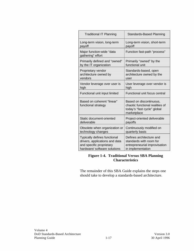
Volume 4DoD Standards-Based Architecture Version 3.0Planning Guide 1-17 30 April 1996
Traditional IT Planning Standards-Based Planning
Long-term vision, long-termpayoff
Long-term vision, short-termpayoff
Major function-wide “datagathering” effort
Function fast-path “process”
Primarily defined and “owned”by the IT organization
Primarily “owned” by thefunctional unit
Proprietary vendorarchitecture owned byvendors
Standards-based, openarchitecture owned by theuser
Vendor leverage over user ishigh
User leverage over vendor ishigh
Functional unit input limited Functional unit focus central
Based on coherent “linear”functional strategy
Based on discontinuous,chaotic functional realities oftoday’s “fast cycle” globalmarketplace
Static document-orienteddeliverable
Project-oriented deliverablepayoffs
Obsolete when organization ortechnology changes
Continuously modified onquarterly basis
Typically defines functionaldrivers, applications and dataand specific proprietaryhardware/ software solutions
Defines architecture andstandards with room forentrepreneurial improvisationin implementation
Figure 1-4. Traditional Versus SBA PlanningCharacteristics
The remainder of this SBA Guide explains the steps oneshould take to develop a standards-based architecture.

Volume 4DoD Standards-Based Architecture Version 3.0Planning Guide 1-18 30 April 1996
This page intentionally left blank.

Volume 4DoD Standards-Based Architecture Version 3.0Planning Guide 2-1 30 April 1996
Section Two: Initiation and ArchitectureFramework
Contents Page
Section description............................................................ 2
Project initiation................................................................ 2
Objectives ......................................................................... 4
Scope ................................................................................ 5
Deliverables ...................................................................... 5
Critical success factors ...................................................... 6
Constraints ........................................................................ 7
Task list ............................................................................ 7
Creating and publishing the deliverable............................. 8
Effectivemess measures .................................................. 11
Technology and tools required ........................................ 11
Staffing skills required .................................................... 12
Completion criteria ......................................................... 13
Issues .............................................................................. 13
Figures
Figure 2-1 Interview Questions for Input toArchitecture Framework ............................2-9
Figure 2-2 Definition of an Architecture Principle ......2-9
Figure 2-3 Sample USMC Principle ..........................2-10
Figure 2-4 Essential Facilitator Skills........................2-13
Figure 2-5 Architecture FrameworkApproval Form ........................................2-14

Volume 4DoD Standards-Based Architecture Version 3.0Planning Guide 2-2 30 April 1996
Section description
1
2
3
45
6
7
This section describes the overall process that isfollowed to initiate the SBA planning activity andto develop the first major deliverable—theArchitecture Framework Document. The followingare the key aspects of this phase:
• Project initiation and positioning within theenterprise
• Development of a general definition of the opensystems development and architectureenvironment
• Definition of an architecture vision for thefuture
• Consideration of a general review ofarchitecture design alternatives
• Identification and documentation of issuesunderpinning the architecture vision.
Project initiation is a critical key to ultimate project successand, as such, is discussed first.
Project initiation Project initiation provides for a smooth transition frominitial project planning to the architecture framework phaseof the project. It is essential that the project initiation stepbe explicitly defined and executed for, without it, theproject will not have the firm foundation needed towithstand the inevitable rough times. Architectureprojects, particularly at the enterprise level, uncover all ofthe basic insecurities of the host enterprise. Sensitivitiesare revealed, sacred cows are questioned, and politicalissues are raised. If these foundation issues are not dealtwith and clearly agreed upon by all involved parties, theproject will falter when these periodic storms hit. Thefacilitator needs to be aware of all these issues and realizethat open lines of communication from the very beginningof the relationship are absolutely essential to the success ofthe project.
By their nature, all architecture engagements are different.As a result, an explicit project initiation step is a key tosuccess. The phases, tasks, roles, and responsibilities willbe affected by the culture of the enterprise, architecture

Volume 4DoD Standards-Based Architecture Version 3.0Planning Guide 2-3 30 April 1996
work that may have already been done by the enterprise,the commitment of resources the enterprise is willing tomake (or conversely insists on making), the preconceivednotions the enterprise has about what an architectureproject entails, and a host of other factors too numerous tolist. Project initiation allows all involved parties to agreeon the customization of the basic SBA planning approachtaking all of these factors into consideration. It then allowsspecific decisions about resourcing and time frames for theagreed-upon tasks. A clear-cut project plan emerges andthe first stage of the plan is kicked off.
The project initiation step is not completed until a plan hasbeen laid out in enough detail for the enterprise to knowexactly what is expected at all points along the way.Obviously, not every single workshop, interview, orbackground session will be scheduled to the day andminute, but the necessary events of the early stages of theengagement should be locked in during project initiation.Also, the critical project infrastructure issues (CSFs) mustall be resolved.
Almost all of the work of project initiation revolves aroundthe key issues of establishing a mutually agreeableresourcing strategy and allocating those resources to tasksthat will result in deliverables and time frames with whichall parties can live. Then, of course, the key early tasks inthe plan will be kicked off.
Architecture Work Group The core team that will be involved in the SBA projectfrom beginning to end is the Architecture Work Group(AWG). This is the group of four to six mid-tier managersand IT personnel from the functional areas. This team willbe responsible for facilitating the SBA process, fordeveloping the overall project plan, for securingappropriate participation by key knowledge workers, andfor ensuring that all documents specified in the project planare completed.
Architecture SteeringCommittee
The key to success in this phase depends on the ability ofthe AWG to help the participants develop a sharedunderstanding of the problems and opportunities related tothe existing environment and then to establish a coherentframework for solving these problems over time—buildinga shared vision and direction. While it is the objective ofevery planning exercise to develop this vision, it is

Volume 4DoD Standards-Based Architecture Version 3.0Planning Guide 2-4 30 April 1996
frequently not achieved for a very simple reason—keyplayers were not involved in the process.
Because of this, it is critical that an Architecture SteeringCommittee (ASC) be formed. This group should becomposed of a mix of functional area and IT professionals.Its size and makeup will differ depending on the scope ofthe SBA effort. If there is a question of team membershipbalance, it is preferable to err on the side of too manyfunctional area professionals. It is paramount that allstakeholders be involved in the team—this includes anyindividuals or enterprises with key influence or other“political” power within the functional area.
The Architecture Framework Document is developed bythe AWG. Together with key knowledge workers (theseare the subject matter experts with specialized skills orknowledge that work on an as-needed basis with theAWG), this team becomes the core entity for developingthe rest of the SBA project.
The bulk of the research for the Architecture FrameworkDocument is conducted by facilitating “fast-path”workshops and interviews with key functional and ITpersonnel. The team produces evolutionary drafts of thedocument until all of the stakeholders enthusiasticallyendorse it.
A multistep process is an effective way not only to identifythe central issues underpinning a standards-basedarchitecture but to help develop the architecture principlesthat will guide the rest of the effort.
It is important to note that this phase of the standards-basedimplementation cycle is of a direction-setting nature.During this effort, a general understanding of the currentenvironment is developed and a high-level definition of thecurrent architecture direction is rendered. Time should notbe spent uncovering minute technical details. That work isbetter left for subsequent steps of the process.
Objectives It is important to produce a comprehensive ArchitectureFramework Document that is easy to understand and thatengages executive commitment. It is also important that thedocument be function oriented—addressing issues that arekey to the success of the functional area(s) included in theeffort.

Volume 4DoD Standards-Based Architecture Version 3.0Planning Guide 2-5 30 April 1996
The AWG should avoid focusing solely on technology andthe application development environment. Executive staffswill often dismiss a technical document because they seelittle benefit in defining technology for technology’s sake;however, a document explaining what technology can do tohelp the enterprise achieve its mission is sure to getexecutive attention.
Scope The scope includes all aspects of the enterprise that mayhave an impact on the future use and deployment of IT—the work of the enterprise and the way IT may be used tosupport it. Key business drivers are defined as well as theissues surrounding current technology. Workshop andenterprise change-related activities are the primary vehiclesby which the Architecture Framework Document isproduced.
Personnel in each functional area within the enterprise areinterviewed by the AWG. The purpose of these interviewsis to:
• Discuss the basic mission of the functional areas
• Identify areas for improvement in current practices
• Begin to determine possible ways that informationtechnology can be used to better support the enterprise.
The AWG then synthesizes the findings of the interviews.The results of this synthesis are a set of architectureprinciples. These principles are then put to the test. They arevoted on and discussed with the ASC. This meeting providesa vehicle for key stakeholders to discuss and agree on how theenterprise should proceed with this very important SBA task.
The principles presented in this deliverable will serve asguidelines for developing the plans that will ultimatelybecome the IT architecture for the enterprise.
Deliverables An Architecture Framework Document that contains:
• Enterprise mission/vision
• Strategic drivers
• IT principles
• Key issues that will impact development of the targetarchitecture.
Volume 4DoD Standards-Based Architecture Version 3.0Planning Guide 2-6 30 April 1996
The major deliverable of this phase is the ArchitectureFramework Document. It is recommended that this documentbe brief in nature, “Executive Summary” in design, and ashighly visual as possible. A sample outline for this documentis included in Appendix I.
The central objective of this document is to provide a broadunderstanding of the IT architecture vision. If the documentis produced successfully, all key stakeholders will possess an“ownership” of the effort.
Critical success factors • Identifying shared interests
• Establishing the ASC and chairperson (effectively the“system owner” team)
• Establishing the AWG and primary contact (effectivelythe “system manager” team)
• Establishing the larger community of knowledge workerswho will participate, either in interviews or workshops
• Establishing the mechanism to officially kick off theengagement for all of the participants identified above andfor the enterprise as a whole
• Providing initial orientation to the architecturedevelopment process for the ASC, the AWG, and thecommunity of knowledge workers who will directlyparticipate
• Supporting the executive level of each functional areawithin DoD
• Establishing a shared vision
• Providing a communication vehicle for promoting thevision of the architecture design
• Assuring key knowledge worker commitment andparticipation
• Agreeing on how, when, and to whom project status willbe reported
• Procuring and setting up workspace and tools for thefacilitator(s) and the AWG.

Volume 4DoD Standards-Based Architecture Version 3.0Planning Guide 2-7 30 April 1996
Constraints Many enterprises have never formally developedarchitec-ture principles. The absence of theseprinciples is a definite constraint to the work team,which relies heavily on such documents in defining themission and vision of the enterprise.
• Commitment and participation of executive staff (ASC)
• Availability of existing source material.
Management must be solicited to dedicate knowledgeablepersonnel to the effort (at least until the necessary visionstatements and principles are created) or the project isdoomed to drag on indefinitely, while the AWG attempts todefine this starting point.
Task list • Initiate project and AWG team building
• Form ASC
• Define interview process
• Conduct interviews
• Analyze existing information
• Evaluate existing data-gathering processes
• Optimize those processes to ensure timeliness andaccuracy
• Reconcile interview data with existing information
• Draft and circulate principles for principles workshop
• Conduct principles workshop
• Review final principles with ASC
• Create Architecture Framework Document outline
• Assign writing, reviewing, and editing tasks
• Draft Architecture Framework Document
• Circulate Architecture Framework Document forcomments and review
• Review Architecture Framework Document with ASC
Finalize and publish Architecture FrameworkDocument.

Volume 4DoD Standards-Based Architecture Version 3.0Planning Guide 2-8 30 April 1996
Creating and publishingthe deliverable
ArchitecureFrameworkDocument
This phase will vary widely in terms of the calendar timerequired for completion based on culture, individual schedules,etc. Ideally, when conducted on an intensive basis, this phasecan be completed in approximately 4 weeks. However, mostenterprises require about 2 months to complete the outline,draft, and final document. The document simply goes throughseveral iterations before approval by the ASC. The process isas follows.
With the ASC as a quality check, the AWG can begin toconduct the interviews necessary to gain insight into thebusiness drivers within the function. If done properly, theseinterviews can also serve the purpose of promoting thearchitecture project throughout the enterprise.
Senior executives and key “thought leaders” within theenterprise should be interviewed. Because of the high exposurethat this activity represents, it is important that the interviewersbe well prepared prior to scheduling the first round ofinterviews.
It is suggested that a set of essential questions be developedjointly across the body of interviewers. This helps theinterviewer anticipate underlying issues and problems beforeactually interviewing key personnel—thus minimizing thepotential for failure. Figure 2-1 highlights general questions tobe asked. These questions can be more detailed depending onthe scope of the SBA endeavor.
Existing models andprinciples
To expedite building the architecture framework, the teamshould review any existing business, work organization,application, and information models, as well as currentarchitecture principles for background. There is no need to“reinvent the wheel” if such materials exist. The modelsprovide input and background to the AWG.
Reconciliation andprinciples workshops
The result of interviews and secondary research of existingmaterial is the development of a set of draft principles. Asthe effort progresses, principles workshops are held. Eachworkshop addresses specific topics such as applications,standards issues, database strategies, and communications.

Volume 4DoD Standards-Based Architecture Version 3.0Planning Guide 2-9 30 April 1996
Sample List of Questions
1. What are your responsibilities today?
2. What are your current and long-term priorities? What stands in yourway?
3. What are the most critical elements for success in your job?
4. How can technology be used to help you succeed?
5. What has been your experience in technology projects in the past?What has made them successful? Why have they failed?
6. What improvements can be made to make your work environmentmore productive? Can technology be used?
7. Would you be willing to commit resources to improving the use oftechnology in your area?
8. Who would you recommend we talk to next regarding the use oftechnology in your area? Would toy help us schedule a meeting?
Figure 2-1. Interview Questions for Input toArchitecture Framework
The purpose of the workshops is to reconcile the views andprinciples with the information uncovered in theinterviews. A group of architecture principles isdeveloped. It is typical for a group to develop 30 to 40different principles for an enterprise’s architecture. Asample principle taken from the USMC project is shownbelow. In addition, a more complete description of how todevelop architecture principles is included in the SBAGuide as Appendix A.
Architecture principles are statements of preferredarchitectural direction or practice. They are simple, directstatements of how an organization wants to use informationtechnology in the long term for five to ten years. Theyestablish a context for architecture design decisions across anorganization and help translate business criteria into alanguage that technology managers can understand. Eachprinciple is accompanied by a statement of the rationalebehind stating the principle and a statement of the principle’simplications.
Figure 2-2. Definition of an Architecture Principle

Volume 4DoD Standards-Based Architecture Version 3.0Planning Guide 2-10 30 April 1996
Principle
Where feasible, the USMC will use Commercial-Off-The-Shelf (COTS) and Government-Off-The-Shelf (GOTS) application components and systems rather than develop them internally.
Rationale
The use of COTS and GOTS applications and components should lead to an environment ofincreasingly interchangeable parts. This kind of environment should be more cost effectiveand efficient than custom development, because multiple “customers” are sharing in thedevelopment and maintenance costs. For similar reasons, training and implementation costsshould be reduced. The time frame from concept to implementation should be reduced bytaking advantage of tested and operationally proven applications and/or applicationcomponents. Finally, the risks normally associated with custom development (e.g., scopechanges, budget overruns, missed target time frames, etc.) are significantly reduced.
Implications
• A process for evaluating and selecting COTS and GOTS applications will be needed.This process must accomplish at least the following tasks:
- Identify user requirements which can be satisfied by purchasing standardcomponents.
- Consider if changing the current functions and processes would enable thepurchase of standard system components without adverse effect on operationalperformance.
- Analyze whether the USMC’s customization needs can be accomplishedoutside the purchased standard component rather than inside it. In so doing,the Marine Corps could subscribe to the vendor’s ongoing maintenancereleases.
• Some BPR may be needed to align the business process with available COTS orGOTS applications.
• A set of standards and measurements for matching a standard component’sfunctionality with the user requirements should be developed. For example, thestandard might state that only systems or components which satisfy 80% of requiredfunctionality should be considered for purchase.
• A repository of available COTS and GOTS applications will be needed. Thisrepository will need to accommodate the definitions of the applications and/orapplication components as well as any predefined interrelationships among theapplications.
• Finally, using COTS and GOTS systems and components will make the USMCreliant on those vendors for maintenance and upgrades. Therefore, a vendorqualification process must be undertaken to assess the potential longevity in themarketplace of vendors of prospective packages.
Figure 2-3. Sample USMC Principle

Volume 4DoD Standards-Based Architecture Version 3.0Planning Guide 2-11 30 April 1996
Effectiveness measures • Degree of consensus achieved with principles
Acceptance of draft Architecture Framework Document
• Amount of rework required
• Management participation
• Awareness of the effort.
The overall objective of this phase is to provide a summarydocument that is easily understood by business managersand IT personnel alike. It is therefore important that thedeliverable be a functionally oriented (rather thantechnically oriented) document and focus on key issues ofimportance to the functional area(s).
The work team will be measured against its ability todevelop a document that the enterprise “buys into.”Granted, this is a very subjective measure. However, it isthe only one that really matters at this stage in the SBAproject—buy-in is the name of the game.
For this reason, minimal rework alone does not guaranteequality work. Sometimes minimal rework points to a lackof management commitment to the effort.
Therefore, effectiveness can only be measured by thecombination of variables listed above. The team will knowif the results of its effort are falling on deaf ears, if fewpeople within the function know about the SBA project andeven fewer senior managers pay it due.
Technology and toolsrequired
• Dedicated war room for team meetings
• Word processing and graphic presentation packages
• Microcomputer and telecommunications capabilities
• Principles templates (see Appendix A)
• Architecture Framework Document outlines (seeAppendix I).
To truly expedite the effort, a project “war room” shouldbe established. It should be equipped with a white boardand markers for brainstorming, PCs for preparing thedocument, a table and a set of comfortable chairs for

Volume 4DoD Standards-Based Architecture Version 3.0Planning Guide 2-12 30 April 1996
conducting meetings and interviews, and plenty of workspace so that the team can get the job done.
The AWG should be equipped with word processing,spreadsheet, and graphics presentation packages so thatthey can develop the Architecture Framework Documenteasily. If possible, the team should be connected to eachother via a network so that the work files can be passedfrom writer to reviewer more efficiently.
In some of the more sophisticated environments, the workroom is staffed with a secretary who can take messages,help with the typing, and assist with the documentpreparation work; however, this is not a prerequisite.
Staffing skills required • Group facilitation skills
• Interview skills
• General functional area knowledge and IT technologybackground
• Project management skills
• Writing and presentation skills.
The key to this effort is the solicitation of managementsupport for the effort. Therefore, it is essential that a goodgroup facilitator is used—one who can manage groupdynamics, understands the SBA process, and can keep thework team on track.
This kind of individual is present in most enterprises;however, many firms feel more comfortable getting theirfacilitation expertise from outside the concern—outsiderstend to be more objective and are less likely to sway theteam for personal gain. Figure 2-4 highlights someessential facilitator skills.
Although the facilitator is important to this effort, he/shedoes not a work team make. The work team must bestaffed with people who possess the qualities listed above,or the effort could be in jeopardy. For this reason, workteam candidates should be screened prior to projectinception—just to make sure the right people are availablefor the job.

Volume 4DoD Standards-Based Architecture Version 3.0Planning Guide 2-13 30 April 1996
List of Essential Facilitator Skills
• Knowledgeable project manager
• In-depth understanding of SBA process
• In-depth understanding of automated tools used in SBAprocess
• Expertise in team building
• Expertise in managing group dynamics
• Ability to communicate in both business and technical terms
Figure 2-4. Essential Facilitator Skills
Completion criteria • Interview schedule completed
• Draft principles document
• Architecture Framework Document deliverable
• Management acceptance.
Ultimately, this phase is completed when the ASC acceptsand signs off on the Architecture Framework Document.While the other items listed above are importantmilestones, the work is not considered complete until allcommittee members “own” the deliverable.
For this reason, it is important for the team to establish asign-off procedure that ensures full committee approval.Many times enterprises will establish a sign-off procedurethat assumes acceptance with no formal reply. This shouldbe avoided. Figure 2-5 illustrates a typical ArchitectureFramework Approval Form for committee sign-off.
A process that requires a written signature has proven to bevery effective. ASC members will pay more attention tothe effort because they want to understand and be inagreement with what they are signing.
Issues • Training required
• Executive participation
• Current workload of work team members
• Consulting support required
• Subject matter expert availability.

Volume 4DoD Standards-Based Architecture Version 3.0Planning Guide 2-14 30 April 1996
Architecture FrameworkApproval Form
Reviewer Name:
Date Received:Date Reviewed:Date Returned:
Date:
Reviewer's Comments:
I concur with the findings contained in the “ArchitectureFramework Document. ”
SignatureDate:
Figure 2-5. Architecture Framework Approval Form
As mentioned throughout, executive commitment and theavailability of key personnel (or key knowledge workers) isessential to the success of this effort. However, there areother issues that an enterprise must face to ensure a qualitydeliverable from this phase.
The need for training and consulting support is oftenoverlooked by enterprises excited about establishing astandards-based architecture. While every function isdifferent (in the skills and talents that its personnelpossess), most require the initiation of training in theplanning technique presented here.
For this reason, most enterprises use consultants to providethe necessary training and to drive the SBA effort—at leastuntil the enterprise becomes self-sufficient (usually afterone or two successful SBA pilot projects have beenconducted at a functional area level).

Volume 4DoD Standards-Based Architecture Version 3.0Planning Guide 3-1 30 April 1996
Section Three: Baseline Characterization
Contents Page
Section description....................................................... 3-2
Objectives .................................................................... 3-2
Scope ........................................................................... 3-3
Deliverables ................................................................. 3-4
Critical success factors ................................................. 3-5
Constraints ................................................................... 3-5
Task list ....................................................................... 3-6
Overview of the baseline activity ................................. 3-7
Creating and publishing the deliverable...................... 3-13
Effectiveness measures............................................... 3-14
Technology and tools required ................................... 3-14
Staffing skills required ............................................... 3-14
Completion criteria .................................................... 3-15
Issues ......................................................................... 3-15
Figures
Figure 3-1 The Data Collection Payoff...................... 3-4
Figure 3-2 Platform Attributes ................................ 3-12
Figure 3-3 Platform Attributes Examples ................ 3-13

Volume 4DoD Standards-Based Architecture Version 3.0Planning Guide 3-2 30 April 1996
Section description
1
2
3
45
6
7
This section describes the overall process that is followed to conduct ahigh-level characterization of existing work organization, information,applications, technology, and standards. This activity includes:
• Reviewing general cost, performance, and security issues related tothe baseline architecture
• Developing a framework for characterizing the current environmentto help the WAG organize its thinking
• Documenting the characterization of the current environment in aBaseline Characterization Document.
Objectives To create a report that characterizes the existing architecture of theenterprise.
Many organizations have undertaken enormous baselineefforts sometimes requiring many months, if not years, tocomplete. The detail that would take years to develop isnot necessary–characterizing the existing situation in just afew months of elapsed time is the goal.
Without the insight that a baseline characterizationprovides, it is difficult to develop truly effectiveimplementation plans needed to lead the organization intoits chosen target architecture. A clear view of the existingIT architecture allows identification of opportunities forchange and a migration plan for implementing thoseopportunities. Without this view of the existing situation,there is the risk of devising a target environment that isvery difficult or impossible to implement.
The SBA process is designed to be “fast path” in nature.That means that traditional long-term inventory efforts willnot be appropriate if the task is to proceed quickly anddeliver results. While large and timely data collectionefforts yield more accurate data, time is sacrificed foraccuracy. If a branch of service or entity already possessesmuch of the baseline data, then most of the work effortshould be spent on characterizing the current environmentwith a high-level description. The difference between agood and bad baseline effort is the degree to which thebaseline characterizes the current environment accurately.The recommended approach is a generic baseline versus adetailed specific baseline.

Volume 4DoD Standards-Based Architecture Version 3.0Planning Guide 3-3 30 April 1996
Scope The enterprise that is being modeled (e.g., a branch ofservice, a subset of a service, the entire DoD):
• Existing views of physical and logical environmentscan be used if readily available.
• Task teams can be formed to develop information aboutthe current environment, if no formal data exists.
• Matrices for categorizing work, information,application, and technology platforms as well as costframeworks can be used.
• Descriptive security classification should be applied toeach application and the technology environmentreviewed.
The AWG should set their sights on conducting a baselineeffort that characterizes the current environment rather thanconducting the most accurate inventory effort. This is notthe same activity as a massive inventory effort! In practice,and as a rule of thumb, 80 percent of the information usedin an architecture design activity derives from 20 percent ofthe data collected. It is therefore inefficient to spend timecollecting the last 20 percent of the data when 80 percent issufficiently accurate in characterizing the currentenvironment. Figure 3-1 illustrates the data collectionpayoff dilemma all AWGs face.
Fundamentally, all IT architectures are built upon existingtechnology platforms. In the end, an IT architecturerepresents how the given sets of existing technologyplatforms are used and structured and the attendantfunctionality they deliver for the individual, the workgroup, the function, or the enterprise.
The task of evaluating and designing a new or alternativearchitecture requires that the AWG have a convenientmethod by which it can characterize the currentarchitecture. After the AWG has created a baseline of theexisting architecture, its relative merits and shortcomingscan be examined. With a baseline in place, assuming thefunction seeks to improve upon the existing architecture,the team will be able to develop a target architecture and anall-important migration plan to assure its successfulimplementation.

Volume 4DoD Standards-Based Architecture Version 3.0Planning Guide 3-4 30 April 1996
Baseline Accuracy
Les
s A
ccu
rate
M
ore
Acc
ura
teTIME
Weeks Months to Years
Figure 3-1. The Data Collection Payoff
Baseline elements A number of elements should be reviewed as inputs to theoverall Baseline Characterization Document. Theseinclude:
• Work organization view
• Information view
• Application view
• Technology view
• U.S. Department of Defense Technical ReferenceModel and Standards Profile (TAFIM, Volume 2) is aframework with which to characterize current profilesin place in different parts of the overall model
• Security design document, which specifies the securityplan for the organization. It contains information aboutsuch issues as security policy, accountability, securityassurance, and security documentation as outlined inthe U.S. Department of Defense Trusted ComputerSystem Evaluation Criteria [DoD 5200.28 STD,December 1985].
Deliverables The major deliverable of this phase is the BaselineCharacterization Document. The DoD recommends thatthis document be brief in nature, “Executive Summary” indesign, and as highly visual as possible. The idea is thatthis document will be used by a large number ofindividuals and organizations as will all deliverables

Volume 4DoD Standards-Based Architecture Version 3.0Planning Guide 3-5 30 April 1996
produced during the architecture development activity.Appendices should contain the results of the baseline datagathering, while the body of the document should containkey conclusions and analyses. This document should showreaders “the forest” rather than focus on “counting trees.”A sample outline for this document is included inAppendix I.
Critical success factors • Commitment of resources to develop inventoryinformation
• Trained leadership with experience in fast path baselineefforts
• Communication vehicle for reporting inventoryinformation
• Key knowledge worker availability.
A key critical success factor is that the senior managementof the function understands, endorses, and enthusiasticallychampions the SBA project. In a time of shared DoDresources, this means committing DoD personnel to workon the project for dedicated periods of time. Therefore, apremium must be placed on time and doing the baselineeffort quickly.
As stated in the previous section, the ASC, composed ofrepresentatives from both the business and IT departments,will act as the “project owner.” This committee is theconduit between the AWG and the rest of the function. Itis key that the ASC makes all concerned organizationsaware of the vital nature of the baseline effort and securescooperation from the same when required.
Constraints Availability of existing architecture input in readilyaccessible form.
Many organizations have never formally developed orcreated baseline models. The absence of these models is adefinite constraint to the AWG, which relies heavily onsuch documents in defining the current environment.
However, these background materials can be developedquickly when the right people are engaged in the effort.There are people within the organization who understandwhat information exists and the level of effort required tocollect data appropriate to the task at hand. Managementmust be solicited to dedicate such knowledgeable personnel

Volume 4DoD Standards-Based Architecture Version 3.0Planning Guide 3-6 30 April 1996
to the effort, at least until the necessary architecture viewsand principles are created, or the project is doomed to dragon indefinitely.
Task list The baseline characterization process follows the basicsteps listed below. A key step in the process is primarydata gathering in the form of workshops with keyknowledge workers in various operational areas.Workshops are conducted with one or more representativesfrom the host organization.
• Initiate baseline task team—identify AWG and taskgroups
• Define inventory scope, effort, and milestones
• Develop application, technology environments,security, cost and platform classifications, and datacollection instruments (templates and tools)
• Assign inventory data-gathering tasks
• Review findings and synthesize results
• Produce first cut Baseline Characterization Document
• Conduct management review of BaselineCharacterization Document
• Refine Baseline Characterization Document
• Distribute Baseline Characterization Document to ASCfor comments and review.
The AWG conducts the overall baseline activity and isresponsible for producing the Baseline CharacterizationDocument.
Data collection The AWG should appoint a small subtask group to conducta baseline effort that characterizes the current computingenvironment. This task group conducts a technicalinventory of the organization’s existing technologyinfrastructure. Inputs to this process will vary widely fromorganization to organization based upon the quantity andquality of documentation available. Business, process, anddata model documents may also be used as input. Physicaldiagrams, logical diagrams, tabular inventory, and financialbudget data will also be valuable.

Volume 4DoD Standards-Based Architecture Version 3.0Planning Guide 3-7 30 April 1996
One recommended source for baseline data is the DefenseAutomation Resources Information Center (DARIC).DARIC maintains an extensive set of database repositoriesthat inventory installed hardware, software, and datarelated to management of information technology withinthe DoD. At the same time that the DARIC resource maybe used to provide useful baseline information to AWGs,DARIC may also be used to review technologycomponents that might be valuable for reuse. It is highlyrecommended that the AWG meet with DARIC personnelto obtain a detailed understanding of DARIC’s capabilitiesand resources.
It may become necessary for the baseline task group toassemble and conduct workshops to derive data from theorganization when it is not otherwise readily available fromDARIC or other conventional sources.
Overview of the baselineactivity
To establish a baseline architecture, an inventory of theexisting computer and communications hardware, systemsoftware, and application systems must be compiled.
The inventory is not intended to be exhaustive. Do notspend an excessive amount of time and effort on collectingthe information. Eighty percent accuracy is sufficient toestablish the basic structure of the baseline. The primarygoal in collecting this baseline inventory is to establish theoverall existing architecture structure and a high-level viewof its robustness on a number of levels, including usersatisfaction, strategic significance, and technical quality.
Baseline inventory The baseline inventory will be compiled by completing aseries of worksheets or templates. A complete set oftemplates, used in the baseline assessment, is included inAppendix B. The templates cover all of these categories:
• Existing work functions and processes
• Technology platform inventory
• Applications inventory
• Initial application assessment
• Various affinity (cross-reference) matrices showing theinterrelationships of the various components of thebaseline architecture.

Volume 4DoD Standards-Based Architecture Version 3.0Planning Guide 3-8 30 April 1996
Work functions andprocesses
This inventory should include all business functions andthe key processes included within the function. For eachfunction, the mission should also be identified. Thesefunctions and processes should be cross-referenced to othercomponents of the baseline architecture in the followingways:
• Functions to data groupings
• Functions to applications
• Functions to locations.
Technology platforms This inventory should include all components of thecomputer processing and communications environment,including the following information:
• Type of platform (in terms of the generic technologyplatforms defined in Section 3 of the SBA Guide) andoutlined below:
- Workstation
- Output/input peripheral
- Local area network (LAN)
- LAN server
- Wide area network (WAN)
- Network interface device
- Concentrator/multiplexer/switching device
- Storage devices
- Mid-range processor
- Large processor.
• Vendor name and model (e.g., IBM 3090, IBM 486 PC,Sun Sparcstation). Also include the capacitycharacteristics in terms of throughput and associatedstorage (memory and access to separate storagedevices).
• Specific technology environments (standards)supported in the following areas:

Volume 4DoD Standards-Based Architecture Version 3.0Planning Guide 3-9 30 April 1996
- User interface
- Operating system
- Communications management
- Database (and/or file) management
- Transaction monitor
- Document management
- Distribution management (e.g., E-mail,electronic data interchange)
- Conferencing management
- Development services (compilers, languages,and tool support)
- Repository services (for systems managementand construction, including data dictionarysupport).
• Platform owner (i.e., who has the budgetary ownershipor responsibility for this platform).
• Platform manager (i.e., who has the day-to-dayoperations responsibility for the platform).
• Platform location (i.e., the physical locations of theplatform, address, building number, and/or otherdesignator which will uniquely define the location).
Initial applicationassessment
As a part of the collection of the existing inventory, aninitial assessment of the application systems should begathered from key application users. Systemdeveloper/maintainers should also give their assessment ofthe more widely used applications.
An initial assessment of each application is neededaccording to the following criteria: user satisfaction,strategic value, and technical quality. As part of theanalysis process, after all templates have been returned,these criteria will be mapped in the following pairs on four-quadrant matrices to allow a high-level determination ofthe recommended disposition of each application:
• User satisfaction versus strategic value

Volume 4DoD Standards-Based Architecture Version 3.0Planning Guide 3-10 30 April 1996
• Technical quality versus strategic value
• Technical quality versus technical evolution.
Mapping attributes toplatforms
One of the key activities of this phase is the developmentof a description of the current environment. This activitymust be simple to accomplish. Most organizations havetechnology platforms in place that handle existingapplications. These platforms, more often than not, aresupported by proprietary technology.
A range of technology platform categories are providedthat will be used in the baseline effort. The criterion forplatform definition is that it must be offered in themarketplace as a product. It must be viable, proventechnology that is available in the marketplace and one thatusers can purchase and implement in the present. Thesetechnology platforms include:
WS • Workstations. Any device ranging from a fixedfunction or dumb terminal to a high-end workstationcapable of complex calculations and graphicrequirements (e.g., 3270 terminal, PC, SUNworkstation).
O/I Per. • Output/input peripherals. Any device that outputs orinputs electronic data (e.g., laser or line printer, imagescanner).
LAN • Local area networks (LANs). Operating systemprotocols associated with local area network solutions(e.g., Ethernet, Token Ring, Starlan).
LAN Server
• LAN servers. Network operating system software andhardware attached to LAN networking solutions thatallows routing, file storage, and user applicationservices (e.g., LAN Manager, Novell, Banyan, 3Com,Netframe Super-Server).
WAN • Wide area networks (WANs). All network servicesoffered by public network providers such as public andvirtual private switched voice, switched and dedicateddata, gateway and enhanced service offerings (e.g.,AT&T, MCI, U.S. Sprint, Telenet, Internet, IBMInformation Network, Tymnet, Telenet, etc.).

Volume 4DoD Standards-Based Architecture Version 3.0Planning Guide 3-11 30 April 1996
Iterfce. • Interface devices. Any device that provides a majorbridge or switch between environments (e.g., TCP/IProuter, DEC router, LAN bridge).
Con./Mux/ Switching
• Concentrator/multiplexer/switching devices. Anydevice that performs a concentration function, amultiplexing function, or a switching function (e.g.,IBM 3705, a NET T-1 multiplexer, an AT&T PBX).
Storage • Storage devices. Any traditional magnetic or opticalstorage device (e.g., floppy disk, magnetic tape, opticaldisk).
Mid-Ran. Proc.
• Mid-range processors. Historically known as the“mini-computer,” this increasingly blurring categoryincludes any processor manufactured for mid-rangeprocessing (e.g., IBM AS400, DEC VAX, HPSpectrum).
Large Proc. • Large processors. Traditional mainframe categoryhistorically dominated by IBM, UNISYS, and Amdahl.Supercomputers, such as Crays, are included at thehigh end of this category.
Technology platformattributes
The various generic platform classifications describedallow a baseline inventory to be made of the existingarchitecture. As IT technology changes, so will thesecategories.
Each platform listed above may be thought of as havingvarious attributes. By categorizing existing platforms anddefining their constituent parts, a standards-based currentarchitecture may be defined and examined in a baselineexercise. It may then be used in subsequent steps to definethe target architecture. Figure 3-2 illustrates these variousplatform attributes.

Volume 4DoD Standards-Based Architecture Version 3.0Planning Guide 3-12 30 April 1996
Generic TechnologyEnvironments/ServicesSupport
Standards Support
Generic Applications Support
ConnectivityCharacteristics
Mid-RangeProcessor
Platform Attributes
Security Evaluation Criteria
Geographic Location
Organizational System Owner Organizational System Manager
Figure 3-2. Platform Attributes
Each of these platforms:
• Has a specific system owner(s) with a DARICreference number
• Has a specific organizational system manager
• Supports an application or application suite and thusserves a role as a generic application supportenvironment or “GAE”
• Provides a technology role for an overall architecturethrough the provision of services as a generictechnology environment or “GTE”
• May be classified in terms of its security evaluationcriteria as outlined in Trusted Computer SystemEvaluation Criteria Summary Chart (p. 109) of theU.S. Department of Defense Trusted Computer SystemEvaluation Criteria [DoD 5200.28 STD, December1985]
• Supports various standards, be they proprietary or openin nature, and are built on either de jure or de factostandards
• Has connectivity and interface characteristics withother technology platforms
• Has specific cost performance characteristics associatedwith its technology life cycle
• Has a specific physical environment.

Volume 4DoD Standards-Based Architecture Version 3.0Planning Guide 3-13 30 April 1996
The following diagram illustrates how the technologyplatform attribute model may be used as a model for abaseline platform—in this case, a mid-range processor.
Platform Attributes
System Manager
System Owner
Connectivity Characteristics
Standards Support
PerformanceProfile
GeographicalLocation
SecurityCharacteristics
GTE/Services Support
GAE SupportMid-RangeProcessor
Current Architecture• Transaction Processing• Batch Processing• Inquiry Processing• Document Processing• Electronic Mail• Document Storage
Current Architecture-Logical Connectivity• Common User Interface• Shared Data• Interactive• Message
Current Architecture-GTEs• User Interface Services• System Management Services• Communication Management Services• Transaction Management Services• Information Management Services• Document Management
Current ArchitectureServices• Name• Directory• Authentication• Access Control• Communications• Time• File• Data• Print• Mail
Current Architecture Role TargetPlatforms Client/Server• IBM 3090• Server• DOS Workstations• Client• DEC Workstations• Client
Current Architecture Logical LinkCharacteristics• IBM 3090• LU 6.2• DOS Workstations• VT 100• DEC Workstations• VT 100
• Quantico• Virginia• Data Center XYZ
• MIPS Rating• Throughput Characteristics
• Physical• Rainbow Series• Industrial Security Manual• Site Security Plans
• USMC
• USMC
• VAX VMS Operating System• X/Windows Presentation Manager• DEC All-in-One X.400 E-Mail• TCP/IP Router• 802.3 Ethernet
Current Architecture Physical LinkCharacteristics• IBM 3090• Batch• DOS Workstations• Interactive Token Ring• DEC Workstations• Interactive Ethernet
Current Architecture CapacityCharacteristics• Number of Transactions• Effective Throughput/Period• Bandwidth Sizing
Figure 3-3. Platform Attributes Examples
Creating and publishingthe deliverable
BaselineCharacterization
Document
The key deliverable out of this phase is the BaselineCharacterization Document. The sole objective of thisdocument is to characterize the current environment and tohighlight systematically the profile and attributes of thecurrent architecture. The baseline will be used as input tothe migration options phase where it will be compared tothe target architecture. This comparison will be used toidentify necessary projects to achieve the vision of theenterprise.
The Baseline Characterization Document provides a totalpicture of the current state of architecture. This phase willvary widely in terms of calendar time required forcompletion based on enterprise culture, individualschedules, etc. Ideally, when conducted on an intensivebasis, this phase may be completed in 8 to 10 weeks.

Volume 4DoD Standards-Based Architecture Version 3.0Planning Guide 3-14 30 April 1996
However, most organizations require about 3 months tocomplete the outline, draft, and final document. Thedocument should go through several draft iterations beforebeing approved by the ASC.
The overall objective of this phase is to provide a summarydocument that is easily understood by business managersand IT personnel alike. It is, therefore, important that thedeliverable be a business-oriented document and focus onkey issues of importance to the function.
Effectiveness measures • Management acceptance of task deliverable
• Comprehensive global characterization of existingenvironment
• Amount of existing inventory data that is reused
• Speed of task execution
• Extent that document is accurate as measured by degreeof acceptance (and percentage degree of completeness).
Technology and toolsrequired
• Word processing and graphic presentation packages
• Architecture team room for meeting
• Spreadsheet tools and/or user friendly, personalcomputer-based database packages for inventorylogging
• Baseline templates (see Appendix B).
The AWG should be equipped with word processing,spreadsheet, database, and graphics presentation packagesso that they can develop the Baseline CharacterizationDocument easily. A key aspect of this activity is thedevelopment of data collection templates to streamline theproject data-gathering exercise. Once these have beencreated, the rest of the baseline effort is more mechanicalthan “creative.”
Staffing skills required • AWG with baseline experience and high familiaritywith existing environment to be baselined; for example:
- An inventory specialist who provides input toArms database
- Network administrators
- System managers

Volume 4DoD Standards-Based Architecture Version 3.0Planning Guide 3-15 30 April 1996
- Data administrators.
• Interview skills
• Writing and presentation skills
• Organizational data collection knowledge
• Familiarity with word processing, presentation,spreadsheet, and database packages that run on mostpopular personal computers.
The key to this effort is the solicitation of managementsupport for the effort. Therefore, it is essential that anAWG leader is selected to facilitate the baseline effort—one who can manage group dynamics, roll up his or hersleeves with the team and participate, and who understandsthe SBA process and can keep the work team on track.
Completion criteria • Inventory scope and deliverable defined
• Inventory completion deadline met on time
• Management acceptance of deliverable
• Completion of Baseline Characterization Document.
Ultimately, this phase is completed when the ASC acceptsand signs off on the Baseline Characterization Document.It is important that all the ASC members as well as theAWG agree that this document is a characterization of thecurrent environment.
The team should obtain a sign-off that ensures full ASCapproval. This was described in the ArchitectureFramework section.
Issues • Workload of work teams
• Availability of existing inventory data
• Successful amount of data collection in short timeframe
• AWG understanding of level of effort and fast pathapproach
• Core team to remain the same.

Volume 4DoD Standards-Based Architecture Version 3.0Planning Guide 3-16 30 April 1996
The need for resources on this task is crucial to projectsuccess. The overall AWG may be at its highest level ofheadcount during the baseline effort.
Given the severe resource limits that are currently the normin the DoD, we recommend that the AWG draft memberson a temporary duty basis for the baseline effort. The“baseline draftees” may then be demobilized and releasedor be assigned to the target architecture phase uponcompletion of the Baseline Characterization Document.However, the core AWG members remain the samethroughout the overall project period.
The ideal profile for an “enlisted” AWG member drafted toconduct baseline work is an individual who possesses asense of urgency and the ability to work on a “fast path”basis to ensure project success.
Keep in mind that the baseline effort is not intended todetermine an action plan for solving the ills that it uncovers(such plans will be developed during the implementationplanning phase of the project). Instead, the intent is tosimply define the current environment, which will act as alogical launch point for subsequent phases of the SBAprocess. What’s next, however, is to define the targetenvironment that the organization seeks to embrace overthe next few years.

Volume 4Dod Standards-Based Architecture Version 3.0Planning Guide 4-1 30 April 1996
Section Four: Target Architecture
Contents Page
Section description....................................................... 4-3
Objectives .................................................................... 4-3
Scope ........................................................................... 4-4
Deliverables ................................................................. 4-5
Critical success factors ................................................. 4-5
Constraints ................................................................... 4-5
Task list ....................................................................... 4-6
Reviewing the principles .............................................. 4-6
Detail the target with four views of the architecture ..... 4-6
Standards model......................................................... 4-22
Creating and publishing the deliverable...................... 4-23
Effectiveness measures............................................... 4-23
Technology and tools required ................................... 4-23
Staffing skills required ............................................... 4-24
Completion criteria .................................................... 4-25
Issues ......................................................................... 4-25
Figures
Figure 4-1 Integrated Model of Four ArchitectureViews ...................................................... 4-4
Figure 4-2 A Work View of the Architecture ............ 4-7
Figure 4-3 Characteristics of Logical Operating
Units ...................................................... 4-10
Figure 4-4 Logical (and Physical) Work Locations . 4-11
Figure 4-5 Generic LOU Decomposition................. 4-12
Figure 4-6 LOU by User Class Affinity Matrix ....... 4-13
Figure 4-7 Information View of the Architecture .... 4-14

Volume 4Dod Standards-Based Architecture Version 3.0Planning Guide 4-2 30 April 1996
Figures (cont’d)
Figure 4-8 LOU by Data Matrix ..............................4-15
Figure 4-9 An Applications View of the
Architecture............................................4-16
Figure 4-10 Information by Application Matrix.........4-17
Figure 4-11 A Technology View of the Architecture .4-17
Figure 4-12 The Review and Approval Cycle ............4-25

Volume 4Dod Standards-Based Architecture Version 3.0Planning Guide 4-3 30 April 1996
Section description
1
2
3
45
6
7
This section describes the overall process by which thearchitecture framework is extended by the AWG. Theseissues for you to approve includes:
• An extension of the vision defined in the ArchitectureFramework Document
• A description of a desired future architecture
• An identification of what can be extended from thecurrent environment into the target environment.
Objectives To develop a Target Architecture Document that specifiesthe profile and attributes of the new technologyenvironment and highlights the key opportunities forimprovement over the baseline. The new architecture neednot be developed based on cost-effective and “business-case-based” criteria. The real world constraints ofcost/benefit analysis and cost justification will beintroduced in the migration options phase of the SBAprocess.
At this step in the process, it is desirable to define a targetarchitecture that can be used to achieve the vision of theorganization in all of the architecture views and, especially,the work architecture. Ultimately, constraints will come tobear on the funding of each project that is needed toachieve the target but, for now, it is sufficient to flesh outthe target to identify the full spectrum of what is needed toachieve the vision of the organization.
Inevitably, the architecture that is implemented will be ablend of the baseline and the target, with architectureprinciples as the foundation stone. Sometimes, anorganization cannot migrate to the target without eitherdisrupting the quality of service provided to the user baseor expending an inordinate amount of resources to getthere. Therefore, it is important that the team take the timeto outline a set of alternative architectures that may becomean interim target until the ultimate target can belegitimately reached.
Figure 4-1 depicts an overall framework within which theAWG can operate to develop the target architecturedeliverable. Each view of the target architecture has some
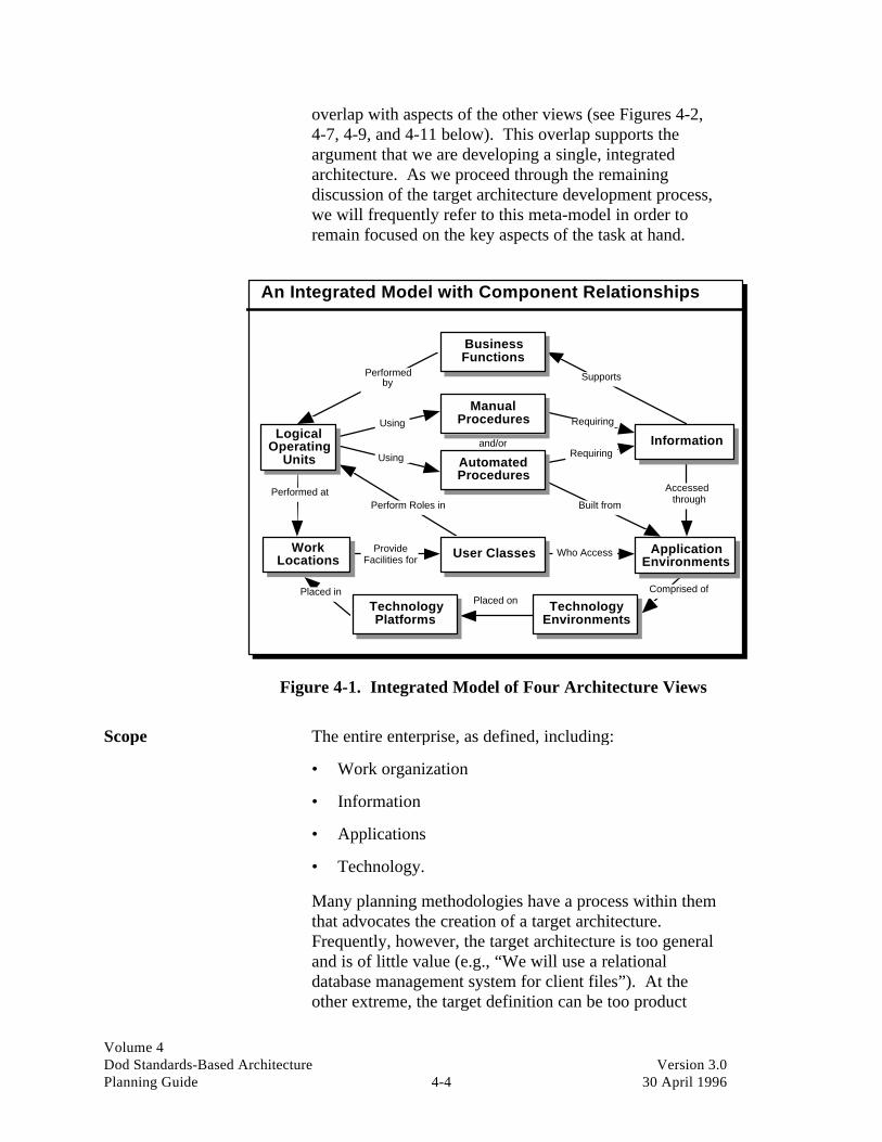
Volume 4Dod Standards-Based Architecture Version 3.0Planning Guide 4-4 30 April 1996
overlap with aspects of the other views (see Figures 4-2,4-7, 4-9, and 4-11 below). This overlap supports theargument that we are developing a single, integratedarchitecture. As we proceed through the remainingdiscussion of the target architecture development process,we will frequently refer to this meta-model in order toremain focused on the key aspects of the task at hand.
An Integrated Model with Component Relationships
Performedby Supports
Using
Usingand/or
Requiring
Requiring
AccessedthroughBuilt from
Who Access
Comprised ofPlaced on
Placed in
Performed atPerform Roles in
ProvideFacilities for
BusinessFunctions
LogicalOperating
UnitsInformation
ManualProcedures
AutomatedProcedures
WorkLocations
ApplicationEnvironments
User Classes
TechnologyEnvironments
TechnologyPlatforms
Figure 4-1. Integrated Model of Four Architecture Views
Scope The entire enterprise, as defined, including:
• Work organization
• Information
• Applications
• Technology.
Many planning methodologies have a process within themthat advocates the creation of a target architecture.Frequently, however, the target architecture is too generaland is of little value (e.g., “We will use a relationaldatabase management system for client files”). At theother extreme, the target definition can be too product

Volume 4Dod Standards-Based Architecture Version 3.0Planning Guide 4-5 30 April 1996
specific to be considered truly open (e.g., “We will useIBM’s DB2 for our client files”).
The key to creating a quality blueprint document isdefining the target architecture in such a way that it wouldremain open and flexible over time as technology,products, and infrastructure evolve.
Deliverables A Target Architecture Document that describes:
• Target architecture with the four views defined, as wellas the key interrelationships across the views. A sampleoutline for this document is included in Appendix I.
Critical success factors An AWG that has:
• A combined general understanding of the currentfunctions and processes of the enterprise
• Experience in long-term functional area and ITplanning
• A practical understanding of the tradeoffs betweenfunctional issues and technology
• A working knowledge of systems development andmaintenance
• An effective communications vehicle between the ASCand the AWG.
It is extremely important to staff the AWG with seasonedprofessionals. To do otherwise can be disastrous. Teammembers must come to the planning table with experiencein business and IT planning. They must also have thepolitical sensibilities to understand the limitations inherentin their work environment.
Constraints • Lack of functional area and technology vision in theAWG
• Lack of full-time commitment to the project bymanagement for key knowledge worker participation inworkshops
• The team’s inability to comprehend the potential of theSBA process.

Volume 4Dod Standards-Based Architecture Version 3.0Planning Guide 4-6 30 April 1996
Task list • Initiate task
• Define target architecture environment planningprocess
• Assign team to review the Architecture FrameworkDocument
• Develop the work view of the architecture
• Develop the information view of the architecture
• Develop the applications view of the architecture
• Develop the technology view of the architecture
• Create the draft Target Architecture Document
• Conduct review with ASC
• Finalize Target Architecture Document
• Distribute Target Architecture Document.
Reviewing the principles In the first phase of developing the SBA framework, thekey component of standards were developed—thearchitecture principles. All target architecture work isbased upon these principles. Principles are similar innature to a federal constitution. They become the centraldocument against which all deliberate and explicitstandards-oriented policies and guidelines are developed.In this phase, the target architecture principles are extendedinto more specific models of the four views of anintegrated target architecture.
Detail the target withfour views of thearchitecture
The target architecture defines the IT environment neededto support the organization over the agreed-upon planninginterval (usually 5 or more years). Its aim is to achieve thevision for the future outlined in the ArchitectureFramework Document for all four views.
Work architecture This work view of architecture is developed by identifyingspecific classes of users within the business environment(e.g., executives, planners, administrators, engineers,recruiters); business locations (e.g., headquarters, salesoffice, plant, warehouse); and a logical representation ofthe business functions that are required to deliver products
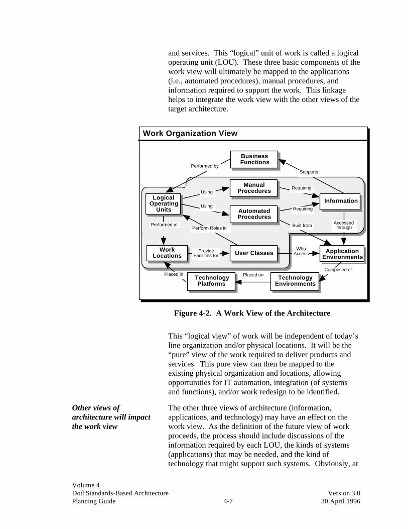
Volume 4Dod Standards-Based Architecture Version 3.0Planning Guide 4-7 30 April 1996
and services. This “logical” unit of work is called a logicaloperating unit (LOU). These three basic components of thework view will ultimately be mapped to the applications(i.e., automated procedures), manual procedures, andinformation required to support the work. This linkagehelps to integrate the work view with the other views of thetarget architecture.
Work Organization View
BusinessFunctions
LogicalOperating
Units
WorkLocations
ApplicationEnvironments
User Classes
Performed bySupports
Requiring
Requiring
AccessedthroughBuilt from
WhoAccess
Performed at
ProvideFacilities for
TechnologyEnvironments
TechnologyPlatforms
Comprised ofPlaced onPlaced in
ManualProcedures
AutomatedProcedures
Information
Perform Roles in
Using
Using
Figure 4-2. A Work View of the Architecture
This “logical view” of work will be independent of today’sline organization and/or physical locations. It will be the“pure” view of the work required to deliver products andservices. This pure view can then be mapped to theexisting physical organization and locations, allowingopportunities for IT automation, integration (of systemsand functions), and/or work redesign to be identified.
Other views ofarchitecture will impactthe work view
The other three views of architecture (information,applications, and technology) may have an effect on thework view. As the definition of the future view of workproceeds, the process should include discussions of theinformation required by each LOU, the kinds of systems(applications) that may be needed, and the kind oftechnology that might support such systems. Obviously, at

Volume 4Dod Standards-Based Architecture Version 3.0Planning Guide 4-8 30 April 1996
this early stage of architecture development, these views ofthe target architecture do not yet exist, but we can do someearly, high-level analysis as a way to help us validate theLOUs in the work view. We want to capture the essence ofthese discussions to feed into the process of developing thedetail of these other views of architecture.
The process facilitator’s responsibility is to ensure that theteam does not get bogged down in detail during thesediscussions and, more importantly, to ensure that a broadenough view of the future is taken.
Although there can be multiple ways to legitimatelysegment an enterprise’s business, discussions generallyyield 10 or fewer “Major Business Areas.” The names forthese major areas should not be confused with similarnames for existing organizational units since they representgeneric business functions, not existing departments orwork groups. Start the process of defining these majorbusiness areas with a brainstorming session with executivesand key knowledge workers from the enterprise. Thefacilitator should go into these sessions with the followinggeneric major business areas “in their back pocket.” Thesegeneric areas are used to guide the discussion if it begins tostray or if the teams get stuck and need a little help:
• Planning
• Selling
• Buying (raw materials acquisition)
• Manufacturing (or whatever the “core business” is)
• Delivery (product distribution)
• Collecting
• Support (including such things as finance, humanresources, administration).
Each major business area is then broken down into itslogical components of work, or LOUs. As with the majorbusiness areas, LOUs are not associated with the currentorganizational structure, its labels, the person performingthe work, or any physical location.
Every LOU (see Figure 4-3) must provide a service andmay have suppliers of products or services. It must be

Volume 4Dod Standards-Based Architecture Version 3.0Planning Guide 4-9 30 April 1996
possible to measure its contribution; if not, it is probablynot a LOU but an activity within a LOU. Each LOU isdefined by the output (or service) for which it isconceptually responsible and the activities it must performto achieve this result. A LOU always delivers its productor service to “customers” within the enterprise or withinexternal actors beyond the boundary of the enterprise beingmodeled. A customer within the enterprise is alwaysanother LOU. A customer beyond the boundary of theenterprise is an external actor (e.g., “true” customers,suppliers, other Government agencies, parentorganizations). Usually, a LOU will also be supplied withinformation or materials.
As the work organization view (i.e., a network of LOUs) isbeing developed, it is important to define the way the workshould be partitioned and defined, not necessarily the wayit is today. This network of LOUs should reflect the mosteffective and efficient way for the work to be done in thefuture. To achieve this, the LOUs themselves and theirinterrelationships will have to be developed, tested byapplying various scenarios to them to see if they hold up,and refined as necessary to optimize the organization of thework within the enterprise. We may think of the majorbusiness processes within an enterprise consisting of theexecution of one or more LOUs in sequence. In this sense,the LOUs are the major steps along the way in a businessprocess.
A key point to remember is that a LOU may participate inmore than one business process at varying points in time.Regardless of how many business processes a LOUparticipates in, its purpose, and the work activities that areexecuted to achieve that purpose, remain constant. In thisway, the enterprise can develop policies, procedures, andsupporting systems and tools for the most stable aspect ofthe business, the LOUs and, by definition, these policies,procedures, and supporting systems and tools willeffectively support all business processes, which are madeup of various combinations of LOUs.
The next step in developing the work view of architectureis to map the LOUs to classes of users who will performthe activities of the LOU. These user classes themselvesare also logical in nature. As such, a physical employee ofthe enterprise may belong to one or more user classes.
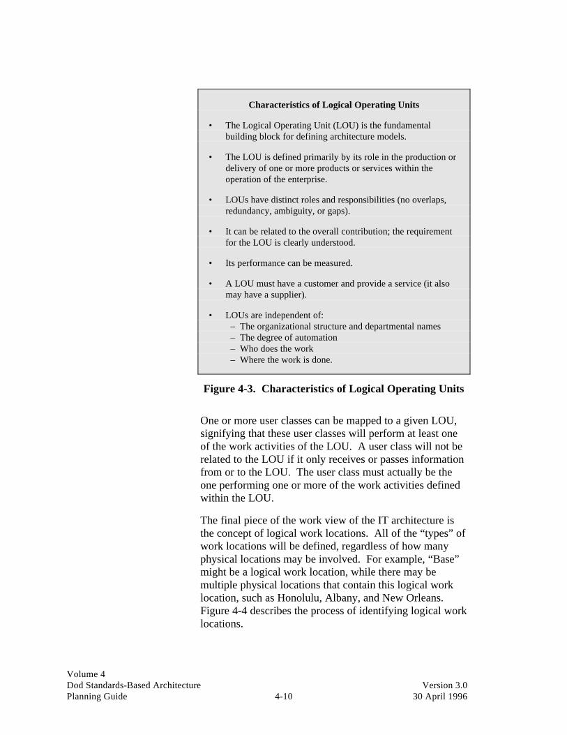
Volume 4Dod Standards-Based Architecture Version 3.0Planning Guide 4-10 30 April 1996
Characteristics of Logical Operating Units
• The Logical Operating Unit (LOU) is the fundamentalbuilding block for defining architecture models.
• The LOU is defined primarily by its role in the production ordelivery of one or more products or services within theoperation of the enterprise.
• LOUs have distinct roles and responsibilities (no overlaps,redundancy, ambiguity, or gaps).
• It can be related to the overall contribution; the requirementfor the LOU is clearly understood.
• Its performance can be measured.
• A LOU must have a customer and provide a service (it alsomay have a supplier).
• LOUs are independent of: – The organizational structure and departmental names – The degree of automation – Who does the work – Where the work is done.
Figure 4-3. Characteristics of Logical Operating Units
One or more user classes can be mapped to a given LOU,signifying that these user classes will perform at least oneof the work activities of the LOU. A user class will not berelated to the LOU if it only receives or passes informationfrom or to the LOU. The user class must actually be theone performing one or more of the work activities definedwithin the LOU.
The final piece of the work view of the IT architecture isthe concept of logical work locations. All of the “types” ofwork locations will be defined, regardless of how manyphysical locations may be involved. For example, “Base”might be a logical work location, while there may bemultiple physical locations that contain this logical worklocation, such as Honolulu, Albany, and New Orleans.Figure 4-4 describes the process of identifying logical worklocations.

Volume 4Dod Standards-Based Architecture Version 3.0Planning Guide 4-11 30 April 1996
Logical (and Physical) Work Locations
• Just as we wish to insulate our systems from the effects oforganizational changes, we wish to insulate systems as muchas possible from the effects of changing physical locations.
• To do this, we identify a set of Logical Work Locations.Similar to the way user classes allow us to categorizeemployees in terms of the roles they play, in a generic sense,the Logical Work Location concepts allow physical locationsto be characterized in terms of the roles they play.
• There can be many Physical Work Locations that contain agiven Logical Work Location.
• A given Physical Work Location may contain more than oneLogical Work Location.
• In all cases, the Logical Work Locations should be set up toallow a reasonable mapping of Logical Operating Units(LOUs) against these locations.
This mapping gives the architecture model the necessarylinkage back to the user class. It also allows for a forwardmapping to Physical Work Locations. These linkages arekey tools in determining where application systems andsupporting IT platforms will be located within the enterprise.
Figure 4-4. Logical (and Physical) Work Locations
With the logical characterization of work operations, users,and locations, supporting systems can be built that arecompletely independent of today’s physical constraints.This provides the ability to develop the most flexible andadaptable systems.
As the user classes and logical work locations are mappedto the LOUs, additional refinements may be made on theLOUs themselves. Discussing who performs the work andwhere the work is performed will frequently lead to betterways to partition the work. No part of the work view ofarchitecture is “cast in concrete” until all of the dimensions(LOUs, user classes, logical work locations) and theirinterrelationships are completely defined.
LOUs and their relationships to the other parts of thearchitecture and the outside world can be graphicallydepicted (see Figure 4-5). This is just another view of thebasic relationships that were outlined in the target

Volume 4Dod Standards-Based Architecture Version 3.0Planning Guide 4-12 30 April 1996
architecture modeling framework earlier in this section asthe “Mother of all Models.”
Generic LOU Decomposition
May besupported
by
May Consume
Create, Retrieve,Update, Delete
AutomatedProcedures
FacilitiesUserClasses
Material
Information
WorkActivities
LogicalOperatingUnit (LOU)
Are comprisedof one or more
This sets thecontext for
Work Activities
Result(Productand/or
Service)
Produce
Areperformed by May Require
Figure 4-5. Generic LOU Decomposition
As an example of how to use the work view of architecturefor analysis, Figure 4-6, the LOU to User Class AffinityMatrix, shows which user classes are likely to perform oneor more of the work activities that make up a given LOU.This matrix is a key tool in the analysis of opportunities forautomation and the linkage of these automated systems towork locations where these various user classes willperform their work.
Information architecture The information architecture is composed of high-levelsubjects that represent all of the information needed toperform the work of the enterprise. The informationarchitecture concentrates on the data being managed insupport of the LOUs of work. Each major collection ofdata needed to support identified functions should becaptured in the information architecture.

Volume 4Dod Standards-Based Architecture Version 3.0Planning Guide 4-13 30 April 1996
User Class
MajorBusiness Area Logical Operating Unit A
cqui
siti
on S
peci
alis
t
Adm
inis
trat
ive
Supp
ort S
peci
alis
t
Air
craf
t Mai
ntai
ner
Air
crew
Arm
or W
arfa
re S
peci
alis
t
Aud
io V
isua
l Spe
cial
ist
Civ
il A
ffai
rs S
peci
alis
t
Com
mun
icat
ions
Ele
ctri
cal E
quip
men
t Mai
ntai
ner
Com
mun
icat
ions
Ope
rato
r
Em
bark
atio
n Sp
ecia
list
Eng
inee
r
Eng
inee
ring
/ U
tilit
ies
Equ
ipm
ent O
pera
tor
Exe
cuti
ve
Fac
iliti
es S
peci
alis
t
Fin
anci
al S
peci
alis
t
Plan Develop and Direct Policy X X
Plan Develop and Establish Requirements X X X X X X X X X X X X X X X
Plan Develop Doctrine and Tactics X X X X
Plan Establish Resource Priorities and Budgets X X X X
Plan Perform Overall Planning X X X
Train Train & Educate X X
Man Acquire Personnel X
Man Manage Personnel X
Equip R&D Equipment and Systems X X X X X X X X X
Equip Procure Equipment, Supplies, and Systems X X X
Equip Support Equipment, Supplies, and Systems X X X X X X
Conduct Ops. Perform Intelligence Process X X X X X
Conduct Ops. Maneuver Forces & Employ Weapon Systems X X X X
Conduct Ops. Perform Operational Planning X X X X X X X
Conduct Ops. Perform Other Directed Duties X X X X X X
Mission Support Administer Distribution of Funds X X X
Mission Support Conduct Ceremonial Support X
Mission Support Conduct Civil Affairs X X
Figure 4-6. LOU by User Class Affinity Matrix
The information view, illustrated in Figure 4-7 is linked tothe LOUs identified earlier, showing where the informationis created, used, modified, and/or deleted, over time. Theinformation architecture includes a discussion of theprinciples of information management as well. The AWGmakes decisions that should facilitate this informationmanagement process. The models should reflect theworkshop participant’s best judgment about the future usesand characteristics of information within the enterprise.User access to this information across various businesslocations is also considered here.

Volume 4Dod Standards-Based Architecture Version 3.0Planning Guide 4-14 30 April 1996
Information Management View
LogicalOperating
UnitsInformation
AutomatedProcedures
WorkLocations
ApplicationEnvironments
UserClasses
TechnologyEnvironments
TechnologyPlatforms
Using Requiring
AccessedthroughBuilt from
Who Access
Comprised of
Placed on
Placed in
Performed at PerformRoles in
ProvideFacilities for
BusinessFunctions
Performed by Supports
ManualProceduresUsing Requiring
Figure 4-7. Information View of the Architecture
The information architecture for the enterprise will containthree levels of detail, subject areas, data groups, and dataattributes.
The LOU to Data Grouping Matrix cross references all ofthe data groupings defined in the information architecture.This establishes the interrelationships among the data andthe LOUs needed to perform the work of the enterprise. Itwill subsequently be used by systems designers as theydevelop the projects presented in the applicationsarchitecture.
The LOU to Data Matrix, illustrated in Figure 4-8, is usedto show which of the LOUs either create, read only,update, or delete data within a given data group. Such amatrix is sometimes referred to as a “CRUD” matrix. Thisis due to the appearance of the letters C, R, U, and/or D inthe cells of the matrix to show respectively Create, Read,Update, and Delete capability by a given LOU. Thismatrix is used in discussions of opportunities forautomation. It is also very useful in decisions regarding thephysical location of application systems and the data itself.

Volume 4Dod Standards-Based Architecture Version 3.0Planning Guide 4-15 30 April 1996
Subject
Agreement Facilities Financial Major Business Data Grouping
Contract/ Roads Structure Budget DisbursementsArea Logical Operating Unit
Agreement & ReceivablesPlan Develop & Direct Policy
Plan Develop & Establish Requirements R R
Plan Develop Doctrine & Tactics
Plan Establish Resource Priority & Budget CRUD R
Plan Perform Overall Planning R R R R
Train Train & Educate R
Man Acquire Personnel
Man Manage Personnel CRUD
Equip Procure Equipment, Supplies, and Systems CRUD R R R
Equip R & D Equipment and Systems CRUD R R R R
Equip Support Equipment, Supplies, and Systems R R R
Conduct Operations Perform Intelligence Process R CRUD CRUD
Conduct Operations Maneuver Forces & Employ Weapons Systems R R
Conduct Operations Perform Operational Planning R R R
Conduct Operations Perform Other Directed Duties R R
Mission Support Administer Distribution of Funds R CRUD
Mission Support Conduct Ceremonial Support
Figure 4-8. LOU by Data Matrix
Applications architecture This view of architecture focuses on the opportunities toautomate aspects of work and/or the access to informationneeded to perform work (i.e., the target application systemsto support the business). (See Figure 4-9.) Using the workview and the information required by each unit of workwithin this view, the team identifies application systemopportunities, or clusters of functionality, required tosupport specific business needs. The application view ofarchitecture shows the information usage and flow. Thearchitecture defines the high-level scope and interfacesamong applications, not the detailed requirements of each.
The team should identify all future applications that will beneeded to manipulate the information and support the workbeing performed. In the process, the AWG should developa set of high-level application descriptions. Thesedescriptions are intended to serve as a first-cut view of themajor applications.
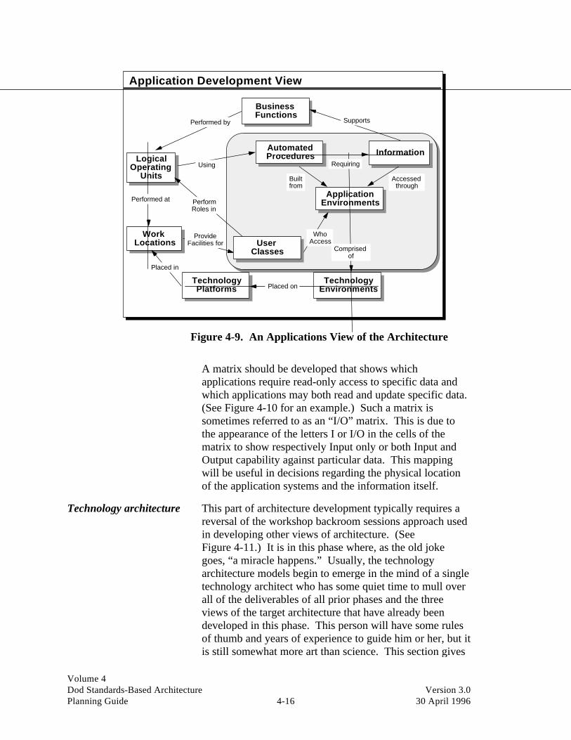
Volume 4Dod Standards-Based Architecture Version 3.0Planning Guide 4-16 30 April 1996
Application Development View
LogicalOperating
Units
InformationAutomatedProcedures
WorkLocations
ApplicationEnvironments
TechnologyEnvironments
TechnologyPlatforms
Using Requiring
Accessedthrough
Builtfrom
WhoAccess
Comprisedof
Placed on
Placed in
Performed at PerformRoles in
ProvideFacilities for
BusinessFunctions
Performed by Supports
UserClasses
Figure 4-9. An Applications View of the Architecture
A matrix should be developed that shows whichapplications require read-only access to specific data andwhich applications may both read and update specific data.(See Figure 4-10 for an example.) Such a matrix issometimes referred to as an “I/O” matrix. This is due tothe appearance of the letters I or I/O in the cells of thematrix to show respectively Input only or both Input andOutput capability against particular data. This mappingwill be useful in decisions regarding the physical locationof the application systems and the information itself.
Technology architecture This part of architecture development typically requires areversal of the workshop backroom sessions approach usedin developing other views of architecture. (SeeFigure 4-11.) It is in this phase where, as the old jokegoes, “a miracle happens.” Usually, the technologyarchitecture models begin to emerge in the mind of a singletechnology architect who has some quiet time to mull overall of the deliverables of all prior phases and the threeviews of the target architecture that have already beendeveloped in this phase. This person will have some rulesof thumb and years of experience to guide him or her, but itis still somewhat more art than science. This section gives

Volume 4Dod Standards-Based Architecture Version 3.0Planning Guide 4-17 30 April 1996
an overview of the thought process that such a technologyarchitect might follow.
SubjectAgreement Facilities Financial
Data Grouping Contract/ Roads Structure Budget DisbursementsApplication System Agreement & ReceivablesAircraft Control System I IAutomated Intelligence Analysis System I I/O I/OAutomated Software Catalog System I I ICareer Management SystemComputer Services Chargeback System I I/OConstruction Estimating System I I/O I/ODeficiency Identification System I I/O I/O I I/ODoctrine Data Base SystemFire Support Control System I IForce Automated Routing and Travel SystemForce Management System I I I IGround Position/Location SystemImagery Dissemination System I IIncident Reporting SystemInformation Technology Capacity Management I I IIntegrated Accounting System I/O I/OInventory Distribution Management System I IJoint Task Force Command System I I
Figure 4-10. Information by Application Matrix
Technology Infrastructure View
BusinessFunctions
LogicalOperating
UnitsInformation
ManualProcedures
AutomatedProcedures
WorkLocations
ApplicationEnvironments
UserClasses
TechnologyEnvironments
TechnologyPlatforms
Performed by Supports
Using
Usingand/or
Requiring
Requiring
Accessedthrough
Built from
WhoAccess
Comprised ofPlaced
on
Placed in
Performed at
PerformRoles in
ProvideFacilities for
Figure 4-11. A Technology View of the Architecture

Volume 4Dod Standards-Based Architecture Version 3.0Planning Guide 4-18 30 April 1996
This area of architecture uses specific component-levelmodels to provide the basis for linking the technology viewof architecture to the work, information, and applicationviews. The linchpin to the other views of architecture isthe generic application environment.
With each application area characterized in terms of itsgeneric application environment(s), the other componentsof the technology architecture can be defined precisely.Using additional component models and genericterminology, the technology architecture will describe theIT infrastructure (framework) required to support theenterprise’s objectives as characterized by the other threeviews of architecture discussed earlier.
Technology architecturebuilding blocks
Three types of building block models (sometimes referredto as constructs) are used in building the overallTechnology Architecture Model. They are describedbelow.
Generic application environments
Generic application environments (GAEs) describe types ofIT applications and tools needed to support specificapplication systems. This is the primary building block inlinking application systems back to the technologyenvironment.
Generic technology environments
Generic technology environments (GTEs) describe types ofservices required to support GAEs (i.e., system software).GTEs provide a means of defining a technologyenvironment that has a standard set of characteristics andattributes. Each GTE uses a set of “servers” that providespecific technical capabilities for the GTE. Like the GTEs,the servers are generic components with standard interfacesto the “clients.” They are built on, but independent of,specific technology implementations. The result is alayered technology that, if implemented through arigorously defined set of interfaces, can isolate applicationsand major technology components from differences in theunderlying technology implementation.
GTEs provide the SBA link from GAEs to the technologycomponents and technology implementations within anorganization’s infrastructure. Each GAE is supported by

Volume 4Dod Standards-Based Architecture Version 3.0Planning Guide 4-19 30 April 1996
one or more GTEs. The combination of the GAEs andGTEs provides the infrastructure components fordelivering systems and services to the organization.
Generic technology platforms
Generic technology platforms (GTPs) describe the deliverycomponents required to run the applications that ride on theGAEs (i.e., “system hardware”).
These generic modeling constructs are planning toolswhich provide a framework for comparing current andtarget environments. They also support standards-basedarchitecture planning. They are not, in and of themselves,the final deliverable but are used as a tool to aid indeveloping the specific technology architecture.
Six technology constructs or GTPs provide fundamentalbuilding blocks in a standards-based architecture. EachGTP can function as a fully independent “architecture” inthat each has an interface along with processing, storage,and communications capabilities. As such, each GTP mayoffer alternative choices in delivery of the same GAE. Forexample, all six constructs are capable of supporting someform of electronic mail, with different associated strengthsand weaknesses. These six GTPs include:
• Intelligent WAN systems
• Establishment-based switching systems
• LAN systems
• Enterprise or corporate processing systems
• Divisional or departmental processing systems
• Desktop or portable intelligent workstations.
It is important to note that the GTPs do not connote aparticular size/capacity. The names for the GTPs connotethe usage of the processor, not size. In fact, departmentalprocessors may be larger or smaller than enterpriseprocessors. Some processors acting as LAN servers couldwell be larger than departmental or enterprise processorsdepending on the way a given organization wishes toorganize its work.

Volume 4Dod Standards-Based Architecture Version 3.0Planning Guide 4-20 30 April 1996
How to use thebuilding blocks
The generic building blocks just described are useful in theprocess of developing the target technology architecture.The end result of such a process is best shown by the use ofan example. The target technology architecture developedfor the U.S. Marine Corps provides an excellent example ofthe output from this process, and the reader is referred tothe target architecture deliverable from that project.
The thought process that was used to produce the USMCtechnology architecture is guided by technology “rules ofthumb” based on experience and informed by the otherviews of the architecture. Specific characteristics of work,information, and applications enter into the interpretationof these rules. Some of these rules are:
• Keep the processor as close as possible to the users ofsystems residing on the processor
• Maximize independence between major applicationgroupings (stepwise escalation from loose coupling totighter coupling)
• Within major groups of applications, look for ways togain tighter coupling (such as shared databases)
• Establish the smallest practical set of standards aspossible
• Maintain vendor independence in standards for as longas possible
• Take locations into account but do not “agonize.”(Follow accepted rules of the road and the effect ofbeing “off” on locations will be minimized.)
• Be pragmatic—do not wait for the ultimateenvironment. Build up to it by accepting some short-term compromises while keeping as many options openas possible.
In addition to this guidance, there are other practical issuesto consider about the placement of applications ontechnology platforms. The support requirements of theapplications can be used to assess which platform is a bestcandidate for placement. For example, highlyindividualistic applications and tools (e.g., text processors,

Volume 4Dod Standards-Based Architecture Version 3.0Planning Guide 4-21 30 April 1996
CAD/CAM, CASE) have a high affinity for the desktop.Applications requiring the need for terminal support orwhich act as the server side of client/server applicationshave a high affinity for departmental or enterpriseprocessors. Finally, infrastructure applications such as E-mail, EDI, and other common services have a high affinityfor LAN or other network servers.
Techniques to arrive at thetarget technologyarchitecture
There are recommended steps to follow to analyze theother architecture views that will facilitate the process ofdefining the target technology architecture.
First, begin by reviewing the characteristics of information.Produce a first cut map of the technology platform usingrules of thumb. Then, review the characteristics ofapplications. This should result in a first cut map of eachapplication to technology platform where the bulk of themost demanding data resides.
The CRUD matrix should next be reviewed to gain insightsabout potential data sharing and the effect this will have ondata distribution. Also, the application to information (I/O)matrix should be reviewed for similar insights (andpotential adjustments).
Each of these steps is performed in an iterative fashionuntil all applications, data, and associated platforms aremapped to logical work locations. By now, a reasonablemodel should begin to emerge that can be tweaked bylooking at the form of information and the potential impacton network traffic. Finally, with all of these stepscomplete, some judgment calls can be made about the styleof computing:
• Distributed presentation
• Remote presentation
• Distributed function
• Remote data management
• Distributed data management.
Capacity requirements should be considered as well tofinalize the model. This last step represents the final“proof” of the model. The information volume, timeliness,and currency requirements, along with application

Volume 4Dod Standards-Based Architecture Version 3.0Planning Guide 4-22 30 April 1996
availability and reliability, can be used to make a guess atthe scale of the processing platform required at eachlocation. The volume, timeliness, and currencyrequirements can be used to categorize the networktransmission capacity needed between locations. The resultof this examination of capacity issues may cause some finaladjustments in application and information distributionacross the network.
Standards model To implement the standards-based infrastructure, it isimportant to consider the scope and depth of the standardsto be adopted. Fundamentally, all cases of standardsadoption require answering three questions:
• What standards should I adopt?
• Where in my architecture should I adopt them?
• When should I adopt them?
Both TAFIM Volumes 2 and 7 should be used in thisphase. Volume 2 suggests a standards-based model foruser interface, database, applications, operating system,communications, languages, management, and otherservices. Volume 7 identifies the standards andspecifications approved by DoD as the method forsatisfying those service areas. Architects are encouraged toselect appropriate standards and specifications fromVolume 7 to form a standards profile. Profiles vary asfunctional requirements vary. The AWG must be preparedto define the details that underpin each section of thediagram for their functional area’s particularimplementation. Appendix C on detailing the targetarchitecture can also be a good reference point for teamsattempting to define the details of the standards model.
De jure vs. de factostandards
A target architecture must be developed such that it willpermit implementation migration towards full standardscompliance — described as either de jure or de facto.
Business requirements should not be compromised strictlyfor the sake of “open systems.” However, whenever a dejure standard is available in effective price/performanceproduct form, it should be implemented as quickly aspossible. Specifically, the de jure standards should be:
• Specified in policies, guidelines, and architecture

Volume 4Dod Standards-Based Architecture Version 3.0Planning Guide 4-23 30 April 1996
• Products and services based on standards-based policiesand guidelines selected whenever viable competitivecost/performance alternatives to proprietary solutionsexist in the marketplace.
Product implementations today tend to be based more onde facto standards than de jure standards. The targetarchitecture effort should take this reality into account.Products based on de facto standards are more availabletoday in the marketplace. A standards-based architecturebased solely on de jure standards may be elegant andpristine in concept but can also be essentially sterilebecause so few of the adopted standards are actually in themarketplace via vendor implementations. All effectivestandards-based architectures must acknowledge the hybridnature of this reality.
Creating and publishingthe deliverable
TargetArchitecture
Document
The target architecture is one of the more creative aspectsof the SBA process. The deliverable is arrived at only aftersignificant thought has been invested in an iterative reviewof the baseline material. The architecture principles shouldbe clearly reflected in the target architecture, and thetechnology view should be capable of supporting the newwork processes envisioned in the target.
• Clarity of Target Architecture Document
• Management acceptance of Target ArchitectureDocument.
Effectiveness measures • Ability to map from current embedded base to targetarchitecture
• Inherent flexibility in the SBA action plans.
The effectiveness of the Target Architecture Document willultimately be determined by the degree to which it is usedby the DoD. As discussed earlier, the document must beeasy to understand and must set a reasonable target,otherwise no one will use it.
Technology and toolsrequired
• Word processing tools (with graphics capabilities)
• Spreadsheet tools
• Business graphics and drawing tools
• Work room for AWG meetings.

Volume 4Dod Standards-Based Architecture Version 3.0Planning Guide 4-24 30 April 1996
It’s important that the blueprint document be highly visual(i.e., contain many diagrams and checklists). The easierthe document is to understand, the more likely it is to beused and referenced.
Appropriate resources should be dedicated to creating auser-friendly blueprint. Some organizations have evengone so far as to hire layout artists to streamline thedocument. While this kind of zeal is not required, toomuch emphasis cannot be placed on making the documenteasy to use (i.e., technology should be available to facilitatethe creation of a quality deliverable).
Staffing skills required • Experienced planners
• Business professionals
• Acquisition experts
• Information technologists
• Writing and presentation skills.
The ASC will provide guidance, direction, and high-levelreview for the work of the AWG. The AWG will beresponsible for assisting in facilitating working sessionsand for producing the deliverables in the planning process.This team will have broad, non-overlapping backgroundsin the business to be modeled.
Key executive and knowledge workers need to be availablefor interviews and/or workshop sessions according to aschedule to be developed within the initial weeks of theproject.
The AWG will develop a working Target ArchitectureDocument. This document will then be reviewed with theASC and other key stakeholders within the enterprise (seeFigure 4-12).
The committee then sponsors a draft document that isreviewed, amended, and approved by the appropriateplayers within the enterprise. This is typically amanagement group composed of functional area heads andthe Chief Information Officer or his/her equivalent. Insome organizations, the chief executive will review theSBA document.

Volume 4Dod Standards-Based Architecture Version 3.0Planning Guide 4-25 30 April 1996
Architecture Steering Committee
Architecture Work Groupand Key Knowledge Workers
Stakeholders
Figure 4-12. The Review and Approval Cycle
Completion criteria • Creation of reviewed and reconciled models
• Creation of target standards (if part of agreed-uponscope)
• Management acceptance of target definition
• Acceptance of Target Architecture Document.
Standards, as articulated in the policies and guidelinessection of this document, will be the core to enablingconstruction of the standards-based infrastructure. Thisdocument will be a key input document to the remainingsteps in the implementation cycle, particularly inidentifying opportunities and migration options.
Issues • Workload of architecture work team(s)
• Target architecture scope management
• Key knowledge workers’ availability for workshops
• Trained, experienced standards-based architects
• Correct understanding and anticipation of the future.
It is essential that the AWG be properly trained in SBAplanning practices and that members be full-timeparticipants in the effort. This implies that managementeliminate the pro forma activities that team members aretypically required to perform.

Volume 4Dod Standards-Based Architecture Version 3.0Planning Guide 4-26 30 April 1996
Failure to make a commitment to this effort seriously canresult in the execution of another tired planning exercisethat carries little or no weight within the function after itscompletion. The old adage “you get out what you put in”truly applies to SBA planning projects.

Volume 4DoD Standards-Based Architecture Version 3.0Planning Guide 5-1 30 April 1996
Section Five: Opportunity Identification
Contents Page
Section description....................................................... 5-2
Objectives .................................................................... 5-2
Scope ........................................................................... 5-2
Deliverables ................................................................. 5-3
Critical success factors ................................................. 5-4
Constraints ................................................................... 5-5
Task list ....................................................................... 5-5
Gap analysis................................................................. 5-5
Payoff categories: the opportunity context................... 5-6
Creating and publishing the deliverable........................ 5-7
Effectiveness measures................................................. 5-7
Tools required.............................................................. 5-7
Staffing skills required ................................................. 5-8
Completion criteria ...................................................... 5-8
Issues ........................................................................... 5-8
Figures
Figure 5-1 Implementation Payoff Approaches ......... 5-4
Figure 5-2 Gaps Between Baseline and TargetArchitectures............................................ 5-6

Volume 4DoD Standards-Based Architecture Version 3.0Planning Guide 5-2 30 April 1996
Section description
1
2
3
45
6
7
This section describes the overall process by which theAWG categorizes and identifies opportunities forexploiting the target architecture. Opportunityidentification is the phase dedicated to identifying theprojects needed to move the organization from the presentto the future (the target architecture). This phase definesthe parameters of change, the major steps along the way,and the major activities to be undertaken.
Objectives To identify key opportunities for implementing the targetarchitecture environment on a “fast path” basis while alsodeveloping a context for development of migration optionsand detailed implementation plans.
In the opportunity identification phase, projects necessaryto move the organization from its current environment (asdefined in the baseline deliverable) to its targetenvironment are identified. This includes a detaileddescription of the automated and non-automated initiativesthat will be necessary to reach the target architecture. Thisphase will flesh out the application, non-application(technology infrastructure), and non-technology initiativesthat should be implemented to achieve the vision of theorganization.
At this stage in the project, it is sufficient to providedocumentation of the essential steps needed to achieve thetarget and not to provide a cost/benefit justification forthese projects. This will be done in the migration optionsphase as projects are justified and ordered into plateaus,and dependencies between projects are identified.
The AWG identifies various opportunities throughworkshops and work group analysis. These opportunitiesare tested and filtered by the business and IT functions.Once finalized, the opportunities are documented in theOpportunity Identification Document.
Scope Throughout the AWG process, numerous opportunities areidentified for introducing standards-based architectures andharvesting benefits associated with the proposedarchitecture solutions. During this phase, the identifiedopportunities are classified with regard to a number of

Volume 4DoD Standards-Based Architecture Version 3.0Planning Guide 5-3 30 April 1996
criteria. This classification scheme becomes the foundationfor migration planning and implementation.
Experience shows that if the project cannot deliverfundamental opportunities on a short-term payoff basiswithin 3 to 6 months, the rest of the standards-basedarchitecture will probably never be implemented. Resultsare critical to success. This places a premium uponidentifying opportunities that are:
• Short and medium term in nature
• Low risk, high payoff in implementation
• Offer a high degree of freedom within the existingarchitecture so that they may be implemented easilyand migrated to as quickly as possible.
As is customary, many opportunities are identified at thesame time that the application component of the targetarchitecture is being developed. Therefore, the systemsintroduced there appear here as project opportunities. Alsoincluded is the definition of infrastructure projects (i.e.,technology features that must exist in order for theapplications to run) and non-technology projects (i.e., non-systems projects that are necessary to achieve the vision ofthe future presented in the target architecture).
Figure 5-1 illustrates the contrast between the traditionalinformation plan and the standards-based fast pathimplementation focus:
Deliverables An Opportunity Identification Document that contains:
• Description of project opportunities
• Dependencies
• Issues to be considered.
In this phase, the team describes the opportunities ingeneral terms, the size and scope of opportunities, as wellas the dependencies that need to be considered when thetime comes to deliver the project. A sample outline for thisdocument is included in Appendix I.

Volume 4DoD Standards-Based Architecture Version 3.0Planning Guide 5-4 30 April 1996
IMPLEMENTATIONPROJECT
PROJECT# 1
PROJECT# 2
PROJECT# 3
TIME
TRADITIONAL IT PLAN PAYOFF
SBA CONTINUOUS PAYOFF APPROACH
Figure 5-1. Implementation Payoff Approaches
Critical success factors • Understanding of the implementation challenges andpayoffs at a high level
• Understanding of the Baseline CharacterizationDocument, Target Architecture Document, and othersource data
• Experience in business and IT planning
• Practical understanding of the tradeoffs betweenbusiness issues, technology, tactical, and operationssettings
• Understanding of Federal procurement guidelines andissues
• Working knowledge of systems development andmaintenance
• Familiarity with IT security planning
• A systems migration planning background
• An effective communications vehicle between teammembers and from the ASC and the AWG.
In this phase, it is important that the AWG balance thestrategic long-term objectives of the target architecturewith a reality-based tactical view of what may be

Volume 4DoD Standards-Based Architecture Version 3.0Planning Guide 5-5 30 April 1996
accomplished in the near- to mid-term time frame. Grandplans are indeed grand; in most cases, they either fail ornever see the light of day. Unfortunately, mostimplementation efforts are judged by the first projectsdelivered rather than on the merits of the overall designrationale. Thus, the demonstrable practicality, efficiency,and effectiveness of the proposed projects will be used toassess the success of this effort.
Constraints • Working within the current architecture paradigm maylimit the team’s ability to “see” new opportunities
• Vision (or lack thereof) may limit successful execution
• Lack of a coherent business case.
Many times, implementation efforts focus only on tacticalprograms. The ability to discern opportunities is onlyincreased when team members have a structured approachand are able to see beyond the constraints of the currentenvironment.
Task list • Initiate task
• Identify gaps between baseline and target architectures
• Identify payoff categories
• Identify key payoff projects
• Draft Opportunity Identification Document
• Conduct review with ASC
• Finalize Opportunity Identification Document
• Distribute Opportunity Identification Document.
Gap analysis Determine the “gaps” between the baseline and the target inall four views of the architecture. Spreadsheets are a goodtool for this. One approach might be: across the top, listall of the “target” components of a given view (e.g., futurebusiness processes, future information facets, futureapplications, or future technology components). Along theleft-hand column, list the current components. In each cellof the spreadsheet, account for all current components.Some current components may be eliminated. Forexample, an “auditing” work process may be “non-valueadded” for the future; therefore, it is eliminated. For casessuch as this, create another column in the spreadsheet

Volume 4DoD Standards-Based Architecture Version 3.0Planning Guide 5-6 30 April 1996
entitled “eliminated.” On the other hand, new componentsmay be added. For example, a new service process mayresult in higher satisfaction for the user of the service. Forcases such as this, create another row entitled “new.” Alleliminated components and new components create gaps.The identification of opportunities must fill these gaps.Figure 5-2 below illustrates this technique for determininggaps.
Target
Current
Audit
(Eliminated)Provide
CustomerService
TakeOrder
FillOrder
SolicitBusiness
(New)
FillOrder
Okay
GAP
GAP
GAPGAP
Figure 5-2. Gaps Between Baseline and TargetArchitectures
Payoff categories:the opportunity context
A number of benefits are associated with open systems andstandards-based architectures. The TAFIM serieshighlights the implementation opportunity initiatives thatsupport portability, scalability, and interoperability ofapplications and systems. As such, it defines an“opportunity vision” for the future. It was devised topermit the DoD to take advantage of the benefits of opensystems and new standards-based technologies available inthe commercial market.
Specific objectives for the DoD TAFIM include:
• Improving user productivity
• Improving development efficiency
• Improving portability and scalability
• Improving interoperability
• Promoting vendor independence
• Reducing life-cycle costs.

Volume 4DoD Standards-Based Architecture Version 3.0Planning Guide 5-7 30 April 1996
These objectives may be used as categories for evaluatingimplementation “payoff” opportunities (see the TAFIM,Volume 2 for more detail.)
Creating and publishingthe deliverable
OpportunityIdentification
Document
The key deliverable in this phase is the OpportunityIdentification Document. It should focus on providing theASC with a high-level understanding of the opportunitiesat hand. As described in the opening of this section, thedocument should focus on highly visible short-term payoffprojects with a “continuous payoff” approach toimplementation opportunity identification. Thedocument’s entire objective is to describe the nature of thetarget architecture opportunities and the role they will playin closing the gap between the baseline environment andthe target architecture.
Effectiveness measures • Degree to which implementation plans can bedeveloped
• Management enthusiasm regarding opportunitiesidentified.
This phase will vary widely in terms of calendar timerequired for completion based on organizational culture,individual schedules, and the formats that organizations areaccustomed to using. Ideally, when conducted on anintensive basis, this phase may be completed in 6 to 10weeks. The draft and final iterations of this documentshould be reviewed with the ASC before any action istaken and changes made accordingly. As with otherdeliverables, the document should go through several draftiterations before being approved by the ASC.
Tools required • Word processing and graphic presentation packages
• Architecture team room for meeting
• Spreadsheet tools and/or user-friendly personalcomputer-based database packages for inventorylogging.
It is key that the AWG put together a high-levelpresentation for the ASC that highlights the features andlogic of the implementation opportunities it has identified.“Selling” the architecture to the ASC must be done on thisbasis.

Volume 4DoD Standards-Based Architecture Version 3.0Planning Guide 5-8 30 April 1996
Staffing skills required • Migration planning skills
• Software modeling skills
• Writing and presentation skills
• Organizational data collection knowledge
• Familiarity with word processing, presentation,spreadsheet, and database packages that run on mostpopular personal computers.
This phase requires individuals who are familiar withproject definition and who understand the requirements ofthe next phase in the process, which will assess the benefitsand risks associated with such projects as well as thepriority which should be placed on each. Ultimately, eachof the projects must be justified in terms of its contributionto the target architecture or as a stand-alone project. Thegoal of this step in the process is not to encourage thecreation of an undisciplined wish list. Rather, there isevery expectation that the minimum set of projects(automated and non-automated) necessary to achieve thevision will have been identified.
Completion criteria • Opportunity Identification Document completed
• Management acceptance of Opportunity IdentificationDocument.
This phase is completed when the ASC accepts and signsoff on the Opportunity Identification Document. It isimportant that all the ASC members, as well as the AWG,have a shared understanding of its content since it willbecome the basis for developing migration options and forimplementation planning.
The AWG should obtain a sign-off that ensures full ASCapproval as with all other steps in the process.
Issues • Executive “buy-in”
• Workload of work team(s)
• Consulting required
• Training required
• Subject matter expert availability.

Volume 4DoD Standards-Based Architecture Version 3.0Planning Guide 6-1 30 April 1996
Section Six: Migration Options
Contents Page
Section description....................................................... 6-3
Objectives .................................................................... 6-4
Scope ........................................................................... 6-4
Deliverables ................................................................. 6-5
Critical success factors ................................................. 6-6
Constraints ................................................................... 6-7
Task list ....................................................................... 6-9
Opportunity categorization......................................... 6-10
Overall benefit classification ...................................... 6-14
Migration planning..................................................... 6-15
Plateau costs............................................................... 6-16
Creating and publishing the deliverable...................... 6-17
Effectiveness measures............................................... 6-18
Technology and tools required ................................... 6-18
Staffing skills required ............................................... 6-18
Completion criteria .................................................... 6-19
Issues ......................................................................... 6-19
Figures
Figure 6-1 Migration Approaches.............................. 6-5
Figure 6-2 Closing the “Gap” Between Baselineand Target Architectures ........................ 6-10
Figure 6-3 Radical Move to Open Standards ........... 6-11
Figure 6-4 Incremental Move to Open Standards .... 6-12
Figure 6-5 Risk: Ideal Migration Path .................... 6-12
Figure 6-6 Risk: Typical Migration Path ................ 6-13
Figure 6-7 Standards: Degrees of Freedom............... 6-1

Volume 4DoD Standards-Based Architecture Version 3.0Planning Guide 6-2 30 April 1996
Figure 6-8 Benefit Matrix ....................................... 6-15
Figure 6-9 Standards Migration............................... 6-17
Figure 6-10 Summary Ballpark Cost Estimates byPlateau................................................... 6-17

Volume 4DoD Standards-Based Architecture Version 3.0Planning Guide 6-3 30 April 1996
Section description
1
2
3
45
6
7
This section describes the overall process by which theAWG identifies and develops migration options for movingto the new target architecture. This section also describesthe overall process by which the AWG categorizes andidentifies opportunities for exploiting the targetarchitecture and shows how such opportunities can bejustified in areas such as their cost-to-benefit ratios or therole they play in providing support for future projects to beimplemented as part of the target architecture. Included inthis activity are descriptions of how the Migration OptionsDocument is developed.
Migration planning is the phase in the process when allessential projects are sorted into plateaus forimplementation planning. The sort process is based on theinterdependencies between projects. In addition, projectsare sorted by strategic value. Those with greatest payoff orstrategic significance should be implemented as early aspossible to take maximum advantage of the value theyrepresent. Finally, cost is considered in developing theimplementation plan. Cost is an important consideration inrecognition of the fact that budgets are limited and most, ifnot all, expenditures must be justified in terms of thebenefits they will provide or in terms of the essentialinfrastructure support they represent. The followingprovides a feel for the content of this phase:
• Estimates of the work and resources required to migratefrom the current environment to the target environmentare developed with resource estimates and responsibilityassignment.
• Comparison of target to baseline architecture isperformed to identify areas where the current situationsatisfies the target requirements and where gaps exist.
• High-level plans for migrating from the current to thetarget architecture are described and dimensioned.
• The migration plan must account for organizationalchange and must also be flexible enough toaccommodate changes in the architecture itself as themigration plan is being implemented. We refer to thislast step as “innovation-proofing” the architecture. Theoutput from this phase is similar in nature to the
Volume 4DoD Standards-Based Architecture Version 3.0Planning Guide 6-4 30 April 1996
document that is produced after the architect hasblueprinted the architecture of a building project—a“construction plan” that tells the builder how to actuallyerect the building.
Objectives To develop a comprehensive, prioritized set of projectinitiatives, which, when completed, will move theenterprise from the current state to the target architecture.
The AWG identifies alternative construction options. Majorcritical implementation steps are developed by the AWG.The detailed implementation plan is then reviewed, not onlywith IT, but with functional area personnel to assure thattime frames are realistic and goals achievable. Projectimplementation responsibilities are assigned, as well asimplementation dates, based entirely on functional arearequirements. This entire phase is documented by the AWGin the Migration Options Document.
Scope This phase will identify all projects required to fullyimplement the target architecture.
The AWG must determine how many areas of the targetarchitecture to tackle at one time as well as theinterdependencies between the components. Theoretically,all four views of the target could be pursued simultaneously.However, practically speaking, they will be easier to manageif they are handled in an independent but related manner.These two conceptual approaches are shown in Figure 6-1.
After a high-level determination is made on which of thesedimensions of the architecture are to be addressed, and ahigh level description of the necessary projects has beencreated, the scope of each project is defined. This shouldinclude a project statement, a scope definition, the majorcomponents of the project, and major steps to be coveredduring the project’s life cycle.
A project scope statement addresses and delimits a projectthat is as small as putting a standard user interface across agroup of applications. Alternatively, the project could be ona much larger scale wherein all major work processes in acustomer service environment, as well as the standards-basedtechnology to support them, are reengineered.

Volume 4DoD Standards-Based Architecture Version 3.0Planning Guide 6-5 30 April 1996
Parallel Migration Segmented Migration
Work Organization
Information
Applications
Technology
Work Organization
Information
Applications
Technology
Figure 6-1. Migration Approaches
Deliverables The Migration Options Document provides specificrecommendations for the priority of the project initiativesthat must be performed to move the enterprise toward thetarget architecture. This document should include athorough discussion of the migration plateaus. A sampleoutline for this document is included in Appendix I.
Plateaus are fashioned to deliver “clusters” of businessbenefit. There are usually three plateaus, with the firstplateau containing some “quick hit” projects as well as thehighest priority major projects:
• Plateau 1 — projects beginning in years one and two
• Plateau 2 — projects beginning in years three and four
• Plateau 3 — projects beginning in years five and beyond.
This document should indicate the priority order of theprojects and ballpark costs associated with each plateau. Thefollowing are the key sources of information (from priorphases of the SBA) that are used in the migration optionsphase.
Baseline applicationassessment charts
These deliverables classify all existing applications as torecommended disposition based on target architecturerequirements and the rating of the existing applicationsagainst standard criteria. The result is that the applicationsare placed in one of the following four categories:
Volume 4DoD Standards-Based Architecture Version 3.0Planning Guide 6-6 30 April 1996
• Renovate/reengineer
• Replace/discard
• Keep/tune
• Asset/build upon.
Target applicationcharacteristics
This deliverable provides a number of characteristics ofenvisioned application systems for use in prioritizing theseapplications. The most important characteristic is theapplication’s perceived contribution to strategic drivers(i.e., a measure of the strategic significance of the targetapplication). This allows the target applications to besorted in order of highest strategic significance.
Target application toexisting application matrix
This deliverable provides the connection between identifiedfuture application functionality and existing applicationsthat may currently supply some (or possibly all) of thisfunctionality. It combines this mapping with theassessment of the existing application and the targetapplication’s strategic significance.
These source deliverables provide much of the rationale forthe prioritization. They are also valuable in arriving at theballpark cost estimates.
Critical success factors • Understanding of implementation challenges andpayoffs
• Experience in business and IT planning
• General cost/benefit orientation towards technologyplanning
• A team that has experience in implementing one or moreof the target areas (i.e., work flow, application, etc.)
• Migration options that avoid full conversions.
Conversions tend to conflict with functional area priorities.Migration to open systems will take many different paths forusers. It will depend upon the embedded base of existingsystems and the rate and speed the enterprise seeks to moveinto target systems over time.
If open systems standards are specified in the targetarchitecture, other considerations must be reviewed. Formost organizations, the move into open systems will meanmaintaining separate environments over some period of time

Volume 4DoD Standards-Based Architecture Version 3.0Planning Guide 6-7 30 April 1996
and running parallel environments. This should be factoredinto the business case for open systems. When the overallcase is examined in terms of long-term benefit, the parallelenvironment will be most cost effective. This is typicallythe case in spite of the fact that the initial and additional costof running parallel environments may skew the cost caseagainst parallel facility-based migration.
Delays in implementing a migration strategy to a standards-based architecture may ultimately increase the number andeffort of conversions required.
Constraints • Inexperience in migration planning may limit theteam’s ability to develop a realistic and acceptable setof migration options.
• The existing work organization may be unable to adjustto the options defined.
As part of the Migration Options Document, it is importantthat the AWG consider issues surrounding organizationalchange processes. These include, but are not be limited to,the establishment of an ongoing architecture review boardand process. The architecture management function itselfneeds to be authorized to specify architecture standards,administer implementation of the additional strategy, roll outstandard tool sets used in the SBA process, and auditcompliance with those standards. Thought should be givento establishing a system architect role or function, if thefunction does not presently exist.
In addition, it would be helpful to describe the various workflow and organizational change processes associated withimplementation of the new architecture. This should be anintegral part of the overall planning process, because this iswhere the synergy of organization and standards workingtogether will be most powerful. These and other conceptsare covered in more detail in the final phase of the SBAprocess, SBA administration.
Some of the issues to be faced in this phase are listed below.The AWG should review, modify, and extend this list tomake it more meaningful to its specific DoD functional area.This can help ensure success in the SBA process.
• Embedded legacy systems must remain in place for sometime for investment or work force resource reasons.

Volume 4DoD Standards-Based Architecture Version 3.0Planning Guide 6-8 30 April 1996
• Open system products which implement de jurestandards simply do not exist for many requirements.
• Proprietary solutions can be very effectiveprice/performance solutions if the larger cost savingsassociated with implementation of open systems are notwell understood.
• Organizational inertia—implementing technologicalchange is as much a cultural, organizational, and politicalchallenge as it is a technical process.
• Lack of cohesion between the IT technical communityand the function-oriented players.
• Lack of an organizational strategic vision can lead tosquandered resources as funds are spent on insignificantor inappropriate efforts.
Lack of a planning and implementation process with whichto identify common requirements for standards-basedsystems.
It is important for the team to remember that with standards-based planning it is possible to eliminate entire classes oftechnology and replace them with new technology platforms.For instance, an organization can:
• Move applications from mainframes to mid-rangeplatforms
• Move applications from mid-range platforms to high-power networked workstations
• Move applications from master/slave implementations tocooperative processing implementations within anexisting proprietary architecture
• Migrate connectivity services (such as E-mail) fromproprietary mid-range platforms into a diverse,multiplatform standards environment (X.400) with aparallel strategy for directory services (transition toX.500)
• Implement UNIX-based workstations and servers andreplace an entire existing application and platformportfolio.

Volume 4DoD Standards-Based Architecture Version 3.0Planning Guide 6-9 30 April 1996
Task list This phase will determine the migration plateaus needed toreach the vision by the target date. It is improbable (andprobably not recommended) that the organization will wantto implement the vision all at once. Usually the vision isattained (or the architecture implemented) by achieving aseries of objectives, each of which builds upon the prior,until the vision is attained. The migration plan includes thetasks, timing, dependencies, and resources needed toachieve all the plateaus described in the migration strategy.
• Determine the gaps
• Use any available examples of applicable work
• Determine pace of change desired by the enterprise
• Determine the migration plateaus needed to reach thevision by the target date
• Determine components (work, information, applications,and technology) required to achieve the vision
• Produce migration plan implementation alternatives
• Include security planning migration considerations
• Draft Migration Options Document
• Conduct review with ASC
• Finalize and distribute document.
Gap analysis This process phase is based on the gap analysis betweenbaseline and target architectures. (See Figure 6-2.) Thepace of change (i.e., how soon the enterprise wants tocomplete the implementation of the architecture), alongwith the priority and interdependence of the projects, willcontribute to defining the plateaus needed to accomplishthis vision.
Once the target architectures have been developed, the AWGshould determine the degree to which the existingtechnology environments, applications, and platformssupport the target environment(s). The data collected duringthe baseline characterization phase should be useful in thiseffort.

Volume 4DoD Standards-Based Architecture Version 3.0Planning Guide 6-10 30 April 1996
Plateau 1Plateau 2
Plateau 3
Target Architec ture
Baseline Architecture
“ENTERPRISEVISION FOR IT”
“GAP”
Figure 6-2. Closing the “Gap” Between Baseline and TargetArchitectures
Opportunitycategorization
To initiate this activity, the AWG begins by categorizingeach of the opportunities identified during development ofthe target architecture into three categories:
• Magnitude classification
• Risk classification
• Degrees of freedom classification.
After the opportunity is reviewed in terms of theseconsiderations, the details of these classifications are put intothe business cases for implementation consideration.
Magnitude classification Primarily, the AWG seeks to determine whether or not theopportunities represent major architecture shifts fromexisting legacy systems in place or an incremental movetowards standards over time. The team seeks to classifyopportunities in terms of “moves” that may be made instandards-implementation over time.
In Figure 6-3, a user has decided to replace an entireproprietary system with a POSIX-compliant architectureimplemented under an X/Windows user interface within ashort time interval. Based on the architecture framework,baseline characterization, and target architecture workconducted by the AWG, this solution appears to be quiteattractive from every dimension but must be characterized asa “radical” move. Every aspect of the “old system”architecture will be changed in quickly moving to the “newsystem” architecture.

Volume 4DoD Standards-Based Architecture Version 3.0Planning Guide 6-11 30 April 1996
Old System
New System
Open, De Jure Standards
Proprietary Standards
TIME
Figure 6-3. Radical Move to Open Standards
In Figure 6-4, the AWG has gone through the same planningprocess as the one previously described. However, it hasdecided to implement only OSI connectivity solutions withinits proprietary “old system” architecture over the next 3years. It will adopt SQL whenever possible in its databasedesign activities, but only for new systems. Old databaseswill remain non-SQL compliant. Other than these twostandards-related activities it will remain, for all intents andpurposes, proprietary in its “new system” architecture,evolving towards “openness” over time. These moves maybe characterized as incremental.
Risk classification In addition to characterizing opportunities as incrementalor radical in nature, they may be characterized in terms ofrisk as shown on the following two matrices. In Figure 6-5the ideal “low risk, high payoff” opportunity is described interms of migration.
Old System
New System
Open, De Jure Standards
Proprietary Standards
TIME
Figure 6-4. Incremental Move to Open Standards

Volume 4DoD Standards-Based Architecture Version 3.0Planning Guide 6-12 30 April 1996
Thus, we may use this example to classify an opportunitywhere the user is moving from a proprietary SDLCcommunications protocol to an open protocol such as X.25.In this case, the user is attempting to connect diversefunctions via standards internationally. The new system isbased on X.25 OSI packet switching protocol. Because X.25is an established international standard and is widelyavailable in products, it is therefore a low risk move. As aresult of its implementation, the two hypotheticalinternational functions will be able to connect their networkstogether quickly. The opportunity is high payoff in nature.
HIGH PAYOFF
LOW PAYOFF
IDEAL OPPORTUNITY
PATH
New System
Old System HIG
H R
ISK
LO
W R
ISK
Figure 6-5. Risk: Ideal Migration Path
More often than not, however, the typical IT manager setsout to deliver a “low risk, high payoff” opportunity only tofind himself or herself implementing a “high risk, lowpayoff” solution. Figure 6-6 shows this situation, ascontrasted with Figure 6-5 above:

Volume 4DoD Standards-Based Architecture Version 3.0Planning Guide 6-13 30 April 1996
HIGH PAYOFF
LOW PAYOFF
HIG
H R
ISK
LO
W R
ISK
SUB-OPTIMAL OPPORTUNITY
PATH
Old System
New System
Figure 6-6. Risk: Typical Migration Path
An example of how an IT manager might set out toimplement standards and end up with a “high risk, lowpayoff solution” opportunity may be illustrated with X.500directory standards.
In this example, a user decides to implement X.500 in a newtarget system for directory management for the evolvingelectronic mail application based on diverse LANenvironments. Since X.500 standards are not complete, theuser assumes the gamble that the X.500 standard will becompleted within 48 months and will be widely available inproducts. In fact, the standard is fully specified andcompleted in the user’s hypothetical 48-month time framebut is not implemented in products as quickly as the userrequires.
In this imaginary instance, the LAN-based electronic mailusers cannot find other electronic mail users on distant LANsthroughout the function, because the system wasimplemented with a key standard architecture componentmissing. The result is chaos.
Degrees of freedomclassification
A third way to conceptualize standards and theirimplementation and categorization is to describe theopportunity in terms of “degrees of freedom.” Degrees offreedom describe the degree to which, given the currentarchitecture, you are free to adopt open-system-based

Volume 4DoD Standards-Based Architecture Version 3.0Planning Guide 6-14 30 April 1996
standards and technology and achieve significant benefitsin a new architecture in relatively short order.
If the current architecture does not allow you to implementopen standards quickly, then you will be consigned to a slowmigration (low payoff). On the other hand, if your currentarchitecture permits you to implement open standardsquickly, you have a high degree of freedom within yourexisting architecture, and you will be able to migrate to yournew architecture quickly (high payoff). This concept isillustrated in Figure 6-7.
OPEN SYSTEMS ALTERNATIVES
PROPRIETARY“LOCK IN”
Figure 6-7. Standards: Degrees of Freedom
Overall benefitclassification
Finally, an opportunity may be classified in terms of itsoverall benefits. These include the degree to which theopportunity provides possibilities for cost reduction andvarious categories of improved IT effectiveness. Thefollowing diagram describes this matrix classification.

Volume 4DoD Standards-Based Architecture Version 3.0Planning Guide 6-15 30 April 1996
LOW
HIGH LOW
HIGH
IT Cost Reduction
IT Effectiveness A
IT Effectiveness B
IT Effectiveness C
Figure 6-8. Benefit Matrix
The business casecost/benefit analysisprocess
Once opportunities have been categorized and classified,the business case cost/benefit analysis may be conducted.
Appendix F describes how the business case and thecost/benefit analysis could be constructed. A samplebusiness case is provided, as well as the steps involved inbuilding the case. These should be taken as only one wayto perform this task. If the enterprise has other preferredapproaches to developing cost/benefit analyses, they can besubstituted.
Once the task is initiated, the AWG must review the baselineand target architecture documents developed in previousphases.
Migration planning Upon review, the team selects a component(s) of the targetarchitecture to consider for implementation and creates theaction plans to implement that selected piece. In doing so,the work group must be careful not to lose track of theinstalled base of applications and technology. Feworganizations can afford to scrap this investment andembrace open systems in a “flash-cut” fashion.
Instead, migration from old to new must be a gradualprocess. As the samples provided in Figures 6-3 and 6-4suggest, these timeline issues must be considered as the teamprioritizes its migration plans. Often, one project must be

Volume 4DoD Standards-Based Architecture Version 3.0Planning Guide 6-16 30 April 1996
completed before another can begin. For instance, anorganization may want to determine its DBMS technologybefore it identifies design generators or CASE tools. Moreexamples of migration paths are included in Appendix E.While not a complete view of all types of projects that willbe included in the migration options, Figure 6-9 depictspotential plateaus to migrate from an existing environment toone characterized by technology standards in the targetenvironment.
Plateau costs To assist in planning for the implementation of an ITarchitecture, it is useful to have a feel for the size of theeffort in terms of staffing and costs. Unfortunately, at thearchitecture level, it is not possible to derive theseestimates with a high degree of accuracy. It is possible,however, to apply past experiences in the form of “rules ofthumb” and standard application development estimates.
Costs will crop up in a number of areas as a result of a seriesof projects. However, to arrive at a reasonable order ofmagnitude cost, we will focus on the following areas:
• The incremental computer processing and networkhardware and system software needed to support theprojects that will move the organization to the desiredtarget architecture
• The application development and/or packageprocurement/modifications required to move to the targetarchitecture
• The non-application initiatives needed to move to thetarget architecture.
Figure 6-10 is a sample summary of these cost projectionsby plateau and type of project as derived from the USMCSBA development project.
These ballpark estimates are intended to help strategicdecision makers understand the resources required toproperly evolve into the next generation of computing andreap all of the benefits that a strong IT environment brings.

Volume 4DoD Standards-Based Architecture Version 3.0Planning Guide 6-17 30 April 1996
UserInterface
Database
Applications
Languages
OperatingSystem
Communications
ManagementServices
Other Services
TODAY 2 - 24 MONTHS 24 - 36 MONTHS
PartialX/WindowsCompliance
Partial SQLCompliance
Partial OSICompliance
Full X/Windows Compliance
Full SQL Compliance
Partial POSIXCompliance
Full OSI Compliance
Figure 6-9. Standards Migration
Project Classification
Plateau 1Estimated
Cost
Application Development/Procurement $9M $7M $9M $25M
Non-Application Initiatives $2M $0M $0M $2M
Computing and Network Facilities $28M $21M $21M $70M
Totals $39M $28M $30M $97M
Plateau 2Estimated
Cost
Plateau 3Estimated
Cost
TotalEstimated
Cost
Figure 6-10. Summary Ballpark Cost Estimates by Plateau
Creating and publishingthe deliverable
The key deliverable in this phase is the Migration OptionsDocument along with the high-level cost estimates. Themigration plan will probably consist of three separateplateaus. Because of the unique time horizons in theFederal Government, it may be desirable to link theplateaus with the 2-year POM process.

Volume 4DoD Standards-Based Architecture Version 3.0Planning Guide 6-18 30 April 1996
MigrationOptions
Document
It should focus on providing the ASC with a high-levelunderstanding of the opportunities at hand while alsoproviding business case backup information that justifiesthe proposed implementation opportunities and schedules.This document should also focus on highly visible short-term “payoff” projects to demonstrate the utility of thisprocess along the way to the target.
After finalization and approval, the document is thendelivered to the rest of the organization. The optionsdocument is extremely valuable to stakeholders who mustprepare for the challenges that SBA implementation brings.
Effectiveness measures • Organization’s ability to accept and execute migrationplans
• Rework required of the Migration Options Document
• Management’s general acceptance of the plans.
In order to achieve management acceptance, the MigrationOptions Document must describe the basic elements of theundertaking (i.e., the major program components andinitiatives).
The components should be such that they are easy to readand understand by functional area managers as well as uppermanagement. They should not dwell excessively on thetechnical dimensions of the architecture, elements thatshould be included in a detailed implementation plan. Forexample, if a communications project is undertaken as partof the larger project, it would be appropriate to state that allbuildings would be wired with token ring or Ethernet wiring,but it would be inappropriate to go into the detailssurrounding wiring closet issues and the link, or the time anddates they will be installed and which project team memberswould accomplish the task.
Technology and toolsrequired
• Workstation and connectivity technology
• Word processing and graphics capabilities
• Dedicated workspace with clerical support.
Staffing skills required • Migration planning expertise
• Writing and presentation skills

Volume 4DoD Standards-Based Architecture Version 3.0Planning Guide 6-19 30 April 1996
• Project planning skills and experience in assigning largerefforts into implementable “chunks.”
Completion criteria • Creation of high-level plans for each component of thetarget architecture
• Migration Options Document deliverable
• Management sign-off.
One of the hallmarks of information technology is that itconstantly changes. IT managers are always confronted withone of two phenomena: The technology they have installedis made obsolete very quickly, or the technology they hadforecasted never materializes. For this reason, werecommend that the Migration Options Document contain acontingency section to address these two dilemmas.
In essence, we recommend that each major architectureproject contain an assessment of the technology and standarddirections possible in the future. With that forecast, werecommend that users develop alternative scenarios forimplementation should the technology or standards setforecasted for project implementation never materialize. Werefer to this part of the process as “innovation-proofing.”
In the DoD, the other volumes of the TAFIM series—whichdeal explicitly with technologies, standards, styles ofcomputing, etc.—are already in place and should evolveover time to provide a large measure of this innovation-proofing input.
No person or organization is entirely successful at predictingthe future, but successful organizations will do it well mostof the time by dedicating resources to technology forecastingand SBA administration.
Issues • Consulting support needed
• Executive “buy-in”
• Workload of work team(s)
• Inventory scope management.
When plotting standards, there are other concerns to beaddressed in the architecture. For instance, users may notwant to “turn on” the proprietary extensions to open systemproducts, such as relational database packages, because that

Volume 4DoD Standards-Based Architecture Version 3.0Planning Guide 6-20 30 April 1996
single action moves them away from being open. Whileattractive functionality may be sacrificed, a passport toopenness has been maintained. The team must keep this inmind as it consider its migration options.
• Consulting required
• Training required
• Key knowledge worker availability
• Existence and maturity of “open” technologies andstandards.
In many instances, one might find architectures based onevolving but currently incomplete standards. This requiresthat “workaround” strategies be developed. If the AWGregards standards on a continuum as we have recommended,this will not be as large a problem as it would appear at firstinspection.

Volume 4DoD Standards-Based Architecture Version 3.0Planning Guide 7-1 30 April 1996
Section Seven: Implementation Planning
Contents Page
Section description....................................................... 7-2
Objectives .................................................................... 7-2
Scope ........................................................................... 7-4
Deliverables ................................................................. 7-5
Critical success factors ................................................. 7-5
Constraints ................................................................... 7-8
Task list ....................................................................... 7-9
Creating and publishing the deliverable........................ 7-9
Effectiveness measures................................................. 7-9
Tools required............................................................ 7-10
Staffing skills required ............................................... 7-10
Completion criteria .................................................... 7-11
Issues ......................................................................... 7-11
Figures
Figure 7-1 Levels of Implementation Planning.......... 7-4
Figure 7-2 The “Results Communication” Cycle ....... 7-7
Figure 7-3 Project Impact on the Architecture........... 7-8

Volume 4DoD Standards-Based Architecture Version 3.0Planning Guide 7-2 30 April 1996
Section description
1
2
3
45
6
7
This section describes the overall process by which theAWG identifies and develops specific implementationplans for moving to the new target architecture. Includedin this activity are descriptions of how the ImplementationPlan Document is developed:
• Implementation project plans for Plateau 1 aredeveloped.
• “Quick hits” for fast payoff projects are identifiedand pursued.
• Organizational communication mechanisms forpromoting success are put in place as part of thearchitecture project effort and in anticipation of theSBA administration phase.
Objectives To develop additional planning detail for the projectinitiatives identified as Plateau 1 of the Migration OptionsDocument
• To define projects that can be completed quickly
• To create effective communication mechanisms forpromoting success.
With the completion of the Migration Options Document,the SBA project is nearly complete. This section of theSBA Guide contains the process for developing theimplementation plans for all Plateau 1 efforts.
The Migration Options Document, along with the otherdeliverables from prior phases of the SBA project, shouldbe used to guide a detailed project scheduling process forthe Plateau 1 initiatives, including specific delivery timeframes and clear assignment of roles and responsibilitiesfor each project.
At this point, the enterprise is well positioned to begin itstransition towards the target IT architecture defined earlierin the SBA process. Enterprise project managers will beable to use these project plans as guides to development.The plans contain information about such issues as what isto be included in the project, the type of talent needed forthe implementation team, and the infrastructure issues thatmay impact the success of the effort.

Volume 4DoD Standards-Based Architecture Version 3.0Planning Guide 7-3 30 April 1996
The plans do not define the total amount of resourcesrequired nor the project schedule because that level ofdetail can only be defined when each project is sanctionedby senior management. However, the details needed to geta project successfully off and running are certainlyavailable within the plans.
As described in the previous section of this SBA Guide, theimplementation projects have, by now, been organized intoplateaus. Each plateau contains a set of interrelatedprojects in priority order. The plans that follow are forthose to be tackled in Plateau 1.
Also included in this document are the project plans for aset of quick hits that the enterprise should strongly considercompleting within the first year of its SBA implementationeffort. The quick hit projects offer a good deal of benefitin a relatively short delivery time as well as providing afoundation for other Plateau 1 projects.
Individual project initiatives should then be kicked off witha preliminary analysis phase. In the initial design phase,more detailed deliverables will be developed showing arefined view of the information and system functionalitythrough conceptual models and supporting documentation.Also, a refined cost and benefit estimate should be made atthis time for each project allowing a “go/no-go” decision tobe made on a project-by-project basis, considering all ofthe interrelationships defined in the architecturedeliverables.
This phase is based upon the very simple notion that if anarchitecture does not begin to deliver concrete benefits inunder 12 months, it has a low probability of beingimplemented overall. As a test of its real world viability intoday’s world of results-oriented management and reward,a program must be able to deliver a concrete payoff projectto ensure that a manager’s year-end personal objectives aremet or the program will not be implemented. For thisreason, it is key that short-term payoffs are identified andimplemented early on in the architecture process. Oncethese “small wins” have been put into place, this phasefocuses on broadening awareness throughout theorganization to induce “culture change.” Mid-term benefits

Volume 4DoD Standards-Based Architecture Version 3.0Planning Guide 7-4 30 April 1996
are then harvested and a benefits measurement program isput in place for the duration of the program.
Scope To define the plans necessary for migration, with anemphasis on quick hits, while the longer-term strategicstandards-based architecture is developed andimplemented. The document has a short-term payofforientation.
It is recommended that, if the AWG wants to deliver adetailed technical implementation plan, technical andoperational professionals be introduced as key playersduring this phase.
A natural question arises from this approach: To whatdegree should the AWG be involved in detailed projectmanagement? The answer depends upon the size and scopeof the implementation project. It is recommended that the“Level 1” high-level project plan be developed by theAWG, and that more detailed project implementation plansbe managed within the operational or business units inwhich they logically reside. Progress updates may then bedelivered to the AWG and ASC. Figure 7-1 illustrates thisrelationship.
Level 1 Project Plan
Level 2 Project Plan
Gre
ater
Det
ail
S
um
mar
y D
etai
l
Project 1
Project 2Project 3
Project 4Project 5 Project 1
Project 2Project 3Project 4Project 5
Project 1
Project 2Project 3
Project 4
Project 5 Project 1Project 2
Project 3Project 4Project 5
Project 1
Project 2Project 3
Project 4
Project 5Project 1Project 2Project 3
Project 4Project 5
Project 1
Project 2
Project 3Project 4
Project 5Project 1Project 2
Project 3Project 4
Project 5
Project 1
Project 2
Project 3
Project 4Project 5 Project 1
Project 2Project 3Project 4Project 5
Sub Project A Sub Project B
Sub Project C Sub Project D
ARCHITECTUREWORK
GROUP
FUNCTION ORSERVICE UNITDEPARTMENT
Figure 7-1. Levels of Implementation Planning

Volume 4DoD Standards-Based Architecture Version 3.0Planning Guide 7-5 30 April 1996
Most organizations have key technical leaders on theAWG, and detailed implementation plans are mostsuccessfully developed within the discrete operational unitsin which they are being implemented.
Some AWGs may elect to split implementation planninginto two levels of activity: a high-level architectureimplementation plan and a secondary technicalimplementation plan.
Deliverables Implementation project plan documents that contain thedetailed road map for migration to the Implementation PlanDocument. A sample outline for this document is includedin Appendix I.
During the migration options phase, a series of migrationsteps were outlined. In this phase, the team characterizesthe size and scope of implementation plans and the timingof the projects, as well as developing alternativecontingency plans.
Critical success factors • Project management and estimating skills
• Detailed planning talent on the team
• Team that is comfortable in working with a short-termfocus.
Standard implementation planning techniques that shouldbe used during this phase have not been discussed. It isassumed that the reader will be familiar with thesetechniques in the same manner in which he/she understandsother processes such as data modeling (which is likewiseoutside the scope of this document, although examples areprovided).
Throughout this document, the focus has been on the needto identify opportunities that provide concrete payoffs inimplementation. If an architecture does not provide initialpayoffs, there is a high probability that the entirearchitecture will never “see the light of day.” Thefollowing needs have been described:
• A short-term focus combined with a “fast path process”
• An architecture and attendant implementation based ondiscontinuous, chaotic business realities of today’s “fastcycle” organization

Volume 4DoD Standards-Based Architecture Version 3.0Planning Guide 7-6 30 April 1996
• Implementation projects that provide project-orienteddeliverable payoffs rather than “grand strategic”payoffs some time in the distant future
• An ongoing process that defines architecture andstandards with room for entrepreneurial improvisationand implementation.
SBA implementation must possess all of these qualities.For this reason, it is recommended that, in addition tostandard project planning techniques, the AWG focus onseveral other aspects of implementation to ensuresuccessful implementation.
“Quick hits”:Implementation of short-term payoffs
There is more than a grain of truth in the saying “in the longrun, we’re all dead.” Nowhere is this more true than inimplementation planning. In today’s typical organizationalculture, short-term (3 to 6 months) payoffs are required as acondition of employment and advancement. If the entireimplementation program is to be a success, it must contain aminimum of one major implementation activity that is anintegral part of the SBA plan and may be capable of beingimplemented in a short time frame. It must be of sufficientsignificance that its implementation will assure the AWGmembers (or their management) of attaining their annualprogram goals and objectives.
When implementation activities are linked to theenterprise’s reward system, things get done and heretoforenon-cooperative organizational task force members beginto make things happen.
The other central objective of providing a short-termpayoff is that the successful implementation may then beused as a pilot case example for the rest of the organizationof how a standards-based architecture can provideimmediate benefits, and that truly major benefits willaccrue to the program if it is followed over time.
Communication:Organizationalawareness programs
Upon identification and implementation of a major short-term payoff opportunity, the AWG should spend asignificant amount of time conducting a “public relationsadvertising program.” Figure 7-2 illustrates therecommended process that AWGs should follow to ensurethat the organization is behind the implementation effortthroughout the SBA life cycle.

Volume 4DoD Standards-Based Architecture Version 3.0Planning Guide 7-7 30 April 1996
It is recommended that workshops or presentations becontinuously conducted throughout the organization afterthe AWG has a solid implementation success on its hands.People or processes that actually “get something done” arerare in most organizations. If projects are successful, thereis a great likelihood that the architecture planningdocuments will be read and implemented throughout theorganization.
PlanImplementation
Project
DeliverResults
CommunicateResults to
OrganizationOrganizational
“Green Light” forMore Projects
Figure 7-2. The “Results Communication” Cycle
Architecture planmodifications
The AWG’s designated implementation team will makeongoing modifications to the overall process as it progresses inimplementation over time. There are times when individualimplementation projects blow up or need to be terminated.Sometimes these projects are outright failures due to poormanagement or resource constraints and the like. At suchtimes, it is sometimes convenient for management to concludethat the “architecture is fundamentally flawed.” Thus,important projects are sometimes eliminated because ofsubproject deliverable failures. The overall architecturebecomes, as it were, the fall guy for a poorly implementedproject.

Volume 4DoD Standards-Based Architecture Version 3.0Planning Guide 7-8 30 April 1996
It is recommended that such failures be carefully evaluated inthe context of the overall architecture project implementationcycle before changes are made to the overall architecture. Innine cases out of ten, implementation strategies and tactics willrequire adjustment, rather than the overall architecture.However, sometimes failed projects do show opportunities toimprove the overall architecture.
Because the architecture is developed on a group consensusbasis, making significant changes requires ASC sign-off. Intheory, one aspect that will not change is the architectureprinciples. These provide the “constitutional” backdrop to theoverall standards-based architecture. If the organization doesdiscover that some principles must be changed, then theequivalent of a “constitutional amendment” process must bedeveloped by the AWG and approved by the ASC. Figure 7-3illustrates this process.
1
Initiation and Architecture Framework7
SBA Administration
6
Implementation Planning
5
Migration Options
4
Opportunity Identification
3
Target Architecture
2
Baseline Characterization
Sub Project A
Project
ProjectProjectProject
Project ProjectProjectProjectProject
Project
Figure 7-3 Project Impact on the Architecture
Constraints An inexperienced implementation planning background willlimit the team’s ability to develop effective plans.
The degree to which highly granular implementation plans aredeveloped will depend upon the skill set and experience of the
Volume 4DoD Standards-Based Architecture Version 3.0Planning Guide 7-9 30 April 1996
AWG. If the AWG is more highly skilled at planning versusimplementation, it might be logical to identify business orservice unit department-level personnel to actually carry outthe detailed implementation planning discussed in this phase.
Task list • Initiate task
• Assign team to build detailed implementation plans forPlateau 1 projects
• Develop cost/benefit case by project
• Produce implementation plans by project
• Develop security implementation plans by project asnecessary
• Identify standards implementation strategy by project
• Identify key interrelationships and dependencies amongprojects
• Establish timeline for each project
• Draft Implementation Plan Document
• Conduct review with ASC
• Finalize Implementation Plan Document
• Distribute Implementation Plan Document.
Creating andpublishingthe deliverable
ImplementationPlan
Document
The key deliverable out of this phase is the ImplementationPlan Document. It should focus on providing the ASC with adetailed understanding of the projects being developed as wellas all traditional project management reporting techniques. Itshould include:
• Major project descriptions
• Milestones and project interrelationships
• Resource requirement definitions
• Project deliverable definitions
• Key responsibilities and accountabilities by projectand program.
Effectiveness measures This phase will vary widely in terms of calendar time requiredfor completion based on project size, scope, organizational

Volume 4DoD Standards-Based Architecture Version 3.0Planning Guide 7-10 30 April 1996
culture, individual schedules, and the resources required toperform the project. We recommend that the implementationproject teams constantly remind management of the need for a“fast path” implementation to ensure rapid deployment ofproject implementation efforts. Effectiveness measuresinclude:
• The ability of the plan to show continuousimprovement and results
• The degree to which implementation plans can bedeveloped
• Management enthusiasm regarding opportunitiesidentified
• Timeliness of project implementation.
The ASC should be kept informed of all status activities asmentioned previously in this section. It is this group that willkeep pressure on their management groups to ensure thatprojects are implemented successfully.
Tools required • Word processing and graphic presentation packages
• Project planning software tools
• Spreadsheet tools and/or user-friendly personalcomputer-based database packages for inventorylogging.
The key deliverables out of this phase are the individualimplementation plans themselves. Therefore, project planningtools, as well as those described above, will be required for thetask at hand.
Staffing skills required • Migration planning skills
• Project management skills
• Writing and presentation skills
• Familiarity with word processing, presentation,spreadsheet, and database packages that run on mostpopular personal computers.
This phase requires individuals who are well-seasonedindividuals in the art and science of migration planning andproject management. If the AWG does not have members with

Volume 4DoD Standards-Based Architecture Version 3.0Planning Guide 7-11 30 April 1996
these traditional skills, the team may be augmented on atemporary basis with personnel outside the team.
Completion criteria • The development of all short-term and mid-term projectplans
• Management review and acceptance.
Successful, on-time implementation of projects identifiedduring the implementation planning effort is the sole measureof how well the completion criteria have been met.
In addition, the degree to which middle- and long-termopportunity projects are pursued is key to the successfulimplementation of the overall architecture. Frequently, suchinitiatives get dropped before “the war is won.” With the focuson short-term payoffs, it is critical that the ASC not abandonits efforts after early “successes.”
Issues • Project management skill capabilities
• Workload of work team(s)
• Business case criteria acceptability
• Consulting required
• Training required
• Subject matter expert availability.
Resource constraints may make project implementation achallenge for both the ASC and the AWG. It is very importantthat all of the issues outlined on the list above be addressed inreviewing all implementation plans.

Volume 4DoD Standards-Based Architecture Version 3.0Planning Guide 7-12 30 April 1996
This page intentionally left blank.

Volume 4 Version 3.0 DoD Standards-Based Architecture 8-1 30 April 1996Planning Guide
Section Eight: SBA Administration
Contents Page
Section description....................................................... 8-2
Objectives .................................................................... 8-3
Scope ........................................................................... 8-4
Deliverables ................................................................. 8-5
Critical success factors ................................................. 8-5
Constraints ................................................................... 8-6
Task list ....................................................................... 8-7
Effectiveness measures................................................. 8-9
Technology and tools required ................................... 8-10
Staffing skills required ............................................... 8-10
Completion criteria .................................................... 8-10
Issues ......................................................................... 8-11
Architecture remodeling............................................. 8-11
Cultural change .......................................................... 8-12
Figures
Figure 8-1 The Continuous Process ImprovementCycle ....................................................... 8-3
Figure 8-2 The Team Reviews Each SBAProject Plan ............................................. 8-5
Figure 8-3 The Entire Organization Should BeIncluded in the SBA Process .................... 8-7
Figure 8-4 The SBA Assessment Document IncludesNew Plans, Revisions to Old Plans,and Lessons Learned................................ 8-9
Figure 8-5 The Organization Must Gain aWorking Understanding of SBAand Learn to Appreciate Its Value.......... 8-12
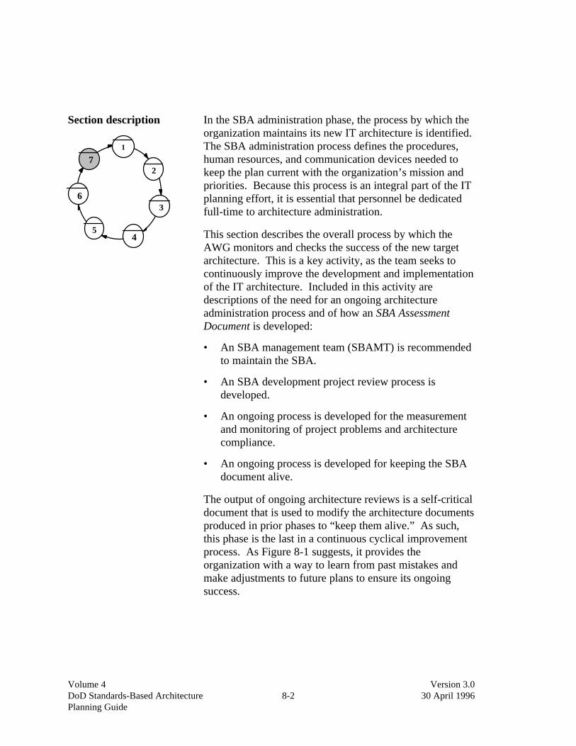
Volume 4 Version 3.0 DoD Standards-Based Architecture 8-2 30 April 1996Planning Guide
Section description
1
2
3
45
6
7
In the SBA administration phase, the process by which theorganization maintains its new IT architecture is identified.The SBA administration process defines the procedures,human resources, and communication devices needed tokeep the plan current with the organization’s mission andpriorities. Because this process is an integral part of the ITplanning effort, it is essential that personnel be dedicatedfull-time to architecture administration.
This section describes the overall process by which theAWG monitors and checks the success of the new targetarchitecture. This is a key activity, as the team seeks tocontinuously improve the development and implementationof the IT architecture. Included in this activity aredescriptions of the need for an ongoing architectureadministration process and of how an SBA AssessmentDocument is developed:
• An SBA management team (SBAMT) is recommendedto maintain the SBA.
• An SBA development project review process isdeveloped.
• An ongoing process is developed for the measurementand monitoring of project problems and architecturecompliance.
• An ongoing process is developed for keeping the SBAdocument alive.
The output of ongoing architecture reviews is a self-criticaldocument that is used to modify the architecture documentsproduced in prior phases to “keep them alive.” As such,this phase is the last in a continuous cyclical improvementprocess. As Figure 8-1 suggests, it provides theorganization with a way to learn from past mistakes andmake adjustments to future plans to ensure its ongoingsuccess.
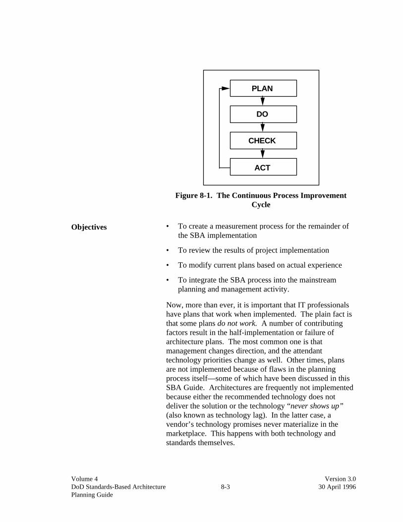
Volume 4 Version 3.0 DoD Standards-Based Architecture 8-3 30 April 1996Planning Guide
PLAN
CHECK
ACT
DO
Figure 8-1. The Continuous Process ImprovementCycle
Objectives • To create a measurement process for the remainder ofthe SBA implementation
• To review the results of project implementation
• To modify current plans based on actual experience
• To integrate the SBA process into the mainstreamplanning and management activity.
Now, more than ever, it is important that IT professionalshave plans that work when implemented. The plain fact isthat some plans do not work. A number of contributingfactors result in the half-implementation or failure ofarchitecture plans. The most common one is thatmanagement changes direction, and the attendanttechnology priorities change as well. Other times, plansare not implemented because of flaws in the planningprocess itself—some of which have been discussed in thisSBA Guide. Architectures are frequently not implementedbecause either the recommended technology does notdeliver the solution or the technology “never shows up”(also known as technology lag). In the latter case, avendor’s technology promises never materialize in themarketplace. This happens with both technology andstandards themselves.

Volume 4 Version 3.0 DoD Standards-Based Architecture 8-4 30 April 1996Planning Guide
The final phase in the SBA planning process is to “reality-check” the architecture to ensure that the original designcriteria are bearing results. The best way to accomplishthis on an ongoing basis is to fully integrate the SBAplanning process into the mainstream managementpractices within the enterprise.
Scope • All projects defined in the implementation plan arewithin scope of the evaluation.
This step is executed once the implementation plans forPlateau 1 projects have been approved. This is an optimaltime for effecting the transition of the SBA process fromthe “experimental” arena into the mainstream managementfunction. By establishing a credible position within themanagement function, the projects coming out of the SBAprocess will have greater likelihood of funding andimplementation. It may be a significant challenge tobecome a full-fledged component of the general businessplanning process, but anything short of this status isassociated with risks to the projects and to the SBA processitself. The ability of the SBA process to achieve suchstatus will, in many cases, reflect the success of theinitiation phase that launched the SBA in the first place.
After a reasonable period has elapsed in theimplementation process (or, alternatively, as a directfollow-on to the delivery of approved plans), the AWGshould conduct a brief review of the projects defined in theImplementation Plan Document to ensure that thoseprojects’ objectives are being met and that payoffs arebeing obtained through the implementation process (seeFigure 8-2.). We refer to this as a “process check” and, assuch, it will provide a quality assurance dimension to theoverall planning process.
This process check of the architecture should occur on acyclical basis throughout the IT planning process. Thischeck should focus on the deliverables of the architecture,as well as on the architecture process itself, and bemodified accordingly.

Volume 4 Version 3.0 DoD Standards-Based Architecture 8-5 30 April 1996Planning Guide
PLAN
¦¦¦
ACTUAL
¦¦¦
VS
Figure 8-2. The Team Reviews Each SBA Project Plan
Deliverables • Establishment of the SBAMT and recommendedprocesses to keep the SBA “alive”
SBA Assessment Document (at a later date in theimplementation cycle, but after the SBA developmentproject concludes)
The architecture is subject to regular assessment and anSBA Assessment Document is produced at each review.The SBA Assessment Document may be developed by theSBAMT. The process of SBA implementation, however,is ongoing and subject to the organization’s commitment tocontinuous process improvement. (Quarterly reviews arerecommended in the first year, semi-annual reviewsthereafter.) A sample outline for this document is includedin Appendix I.
Critical success factors • The organization must be willing to sponsor the SBAprocess as an ongoing management activity.
• A team review of the process that solicitsorganizational buy-in must be used.
• Time must be dedicated to this effort.
• Key knowledge workers must participate as required.
• Results must be communicated.
Modifications to existing plans must be made.
It is essential that the organization establish a reviewprocess and dedicate resources to the effort. Perhaps thegreatest reason for implementation failure is the simple, butoften overlooked, requirement to obtain organizationalbuy-in and make the architecture implementation process ateam-based effort.

Volume 4 Version 3.0 DoD Standards-Based Architecture 8-6 30 April 1996Planning Guide
Much of this activity is organizational and political. In theend, politics is the art of inclusion. Any success enjoyedearly on in the initiation phase will contribute to continuityof the process now that the process deliverables have allbeen approved. The real challenge starts now asimplementation plans are to be put in place. If initiationwas not successful, there remains much to do in positioningthe SBA process within the organization. Any organizationpursuing standards on a managerial dictatorship model willrun a much higher probability of failed implementationsthan the more team-oriented process that has been outlinedthroughout this SBA Guide.
In the area of standards-based architecture, it is paramountthat the AWG build into the overall process a reviewsystem to ensure compliance with the objectives set out bythe Architecture Framework Document, BaselineCharacterization Document, Target ArchitectureDocument, Opportunity Identification Document,Migration Options Document, and Implementation PlanDocument.
Constraints • Fear of being labeled a failure can undermine thiseffort.
• Other priorities can also limit the effort that participantscan dedicate to this project.
As Figure 8-3 suggests, the key to success in establishingan assessment process is to have the plans owned by aswide a team as possible across the enterprise (rather than aset of individuals with “agendas” ready to assign blame forfailure).
Perhaps the largest constraint is management’sunwillingness to dedicate the resources needed to keep theSBA in the forefront of activities in the systemsdevelopment and/or work redesign arena. The ASC mustbe ready to address this issue in order to create the team-oriented environment necessary to make SBA a success.
In this new kind of environment, assessment and reviewbecome less personally and politically charged. The resultis that the assessment process becomes easier tosuccessfully conduct. This form of organizational behavioralso encourages successful implementation in the firstplace.

Volume 4 Version 3.0 DoD Standards-Based Architecture 8-7 30 April 1996Planning Guide
SBAProcess
Figure 8-3. The Entire Organization Should BeIncluded in the SBA Process
Task list • Launch the implementation plan, staff the SBAMT,and establish the ongoing process to be followed.
The following tasks can only be done after some progresshas been made on the project initiatives defined in the SBAimplementation plans (i.e., after the SBA development“project” has concluded).
• The SBAMT maps results against the ArchitectureFramework Document, the Implementation PlanDocument, and their measurement criteria.
• Current project and future plans are reviewed.
• Appropriate modifications are made and distributed tothe review committee and the appropriate projectmanagers.
• “Lessons Learned” are developed and included in theSBA Assessment Document for distribution.
The first step in the assessment process is to establish anSBAMT. This team should be staffed with experiencedplanners and technologists who have a deep-rootedunderstanding of the implementation projects.
Once established, the team must conduct a generalassessment of the projects to see if, in fact, the projects arebeing implemented. This is done by mapping the results

Volume 4 Version 3.0 DoD Standards-Based Architecture 8-8 30 April 1996Planning Guide
against the implementation plans and asking some hardquestions, such as:
• Is the architecture framework still valid? Should any ofthe architecture principles be modified? Which onesand why? What has changed?
• What were the benefits of the identified projects? Costsavings, value-added benefits, or softer long-termintangible benefits?
• Have adopted standards been materially implementedin the organization? How far along has the standardsroad been traveled? How far, given this process check,do we have yet to go? Have we gleaned 80 percent ofthe benefit already or is there still significant payoffdown the road?
• Does the organization recognize the payoff that hasbeen achieved?
• Given the current state of implementation, have anyother payoffs been obtained that may not have beenoriginally predicted (the Opportunity IdentificationDocument should be reviewed in this context)?
• In general, do the plan’s standards appear to bechanging?
• Have any standards, targeted as important, not yetmatured as much as was originally anticipated by thispoint in time?
• What is the status of the technology that was selectedfor implementation? Has it “shown up on time” in themarketplace?
After these questions have been answered, adjustments tothe original plans should be made (i.e., if implementation isnot working for tactical reasons, specific steps will have tobe developed to produce “workarounds”) and reviewedwith the ASC.
After review of the plans, the team should step back fromthe assessment and begin to analyze the exact cause of theshifts of emphasis. These “lessons learned,” together withthe modified plans, become the SBA Assessment Document(see Figure 8-4.).

Volume 4 Version 3.0 DoD Standards-Based Architecture 8-9 30 April 1996Planning Guide
ECK
T
DO
PlansHECK
CT
O
AssessmentProcess
Plan
Do
Check
Act
LessonsLearned
NewPlans
Figure 8-4. The SBA Assessment Document IncludesNew Plans, Revisions to Old Plans, and Lessons
Learned
Often overlooked, documenting the lessons learnedbecomes very valuable to the review team when definingthe modifications to future plans, and it helps futureimplementation teams to “not make the same mistaketwice.”
Effectiveness measures • Organizational buy-in to the process measured byactive and enthusiastic involvement
• Implemented architecture attributes are measured andassessed
• Ease of plan modification
• Communication mechanism.
The assessment effort can be judged by the degree to whichthe assessment team can examine SBA results to date anddetermine the appropriate actions to take to keep thearchitecture process on track. Ultimately, the effectivenessof a given assessment can only be measured by the successof future implementations.
Technology and toolsrequired
• Workstation and connectivity technology
• Word processing and graphics capabilities
• Dedicated workspace with clerical support.

Volume 4 Version 3.0 DoD Standards-Based Architecture 8-10 30 April 1996Planning Guide
Staffing skills required The assessment team is typically composed of membersfrom the original SBA AWG and a few implementationproject managers. While it is true that this team meets onlya few times a year, management must be prepared toreassign workloads and the like because sometimes theeffort needed to complete the assessment can be quiteextensive. The staffing skills required include:
• General knowledge of SBA
• Planning skills
• Subject matter experts (as needed).
Occasionally, the assessment team will need to reworkexisting plans. They will need to call upon key knowledgeworkers who have working knowledge of specific projectsor technologies. Management must be willing to commitwhat it takes to keep the SBA process alive and on track.
Completion criteria While architecture assessment is an ongoing effort, aparticular review cycle can be considered complete when:
• Each SBA project status and plan has been reviewedand compared against the architecture principles andtarget architecture plans.
• Lessons learned have been documented.
• The completed assessment document has been reviewedand approved by the ASC.
Ultimately, it is the ASC’s decision as to when a givenassessment effort is complete (i.e., the committee isresponsible for the success of the SBA effort as a whole).
Issues • Training needed
• Consulting needed
• Remodeling the core architecture may becomenecessary
• Time must be spent changing the culture such thatreviews are seen as a process improvement vehicle andnot as an exercise in “pointing the finger.”

Volume 4 Version 3.0 DoD Standards-Based Architecture 8-11 30 April 1996Planning Guide
Besides the training and consulting support needed forproper architecture assessment, there are two major issuesthat can impact this phase: The extent of architectureremodeling needed and the management of cultural change.
Architecture remodeling When should you remodel? When one of the architectureprinciples has changed. Another reason for remodelingcould be that a major change in technology took place thatwas so significant that your architecture plans did notanticipate it; however, this will become increasingly rare.One of the major benefits of standards planning is thatstandards, unlike the underlying technology itself, changefar less frequently.
In theory, you should never have to change yourarchitecture framework if the architecture principles neverchange; however, they do change from time to time. Whenthis happens, the review team should discuss and confirmthe perceived changes with the ASC.
If necessary, the committee can sanction a task force to donecessary rework of the affected SBA documents.However, this step is usually not required, because theassessment team is more than likely composed of the samepersonnel who developed the original plans.
Plans
Construction
Review
Adjustments
Figure 8-5. The Organization Must Gain a WorkingUnderstanding of SBA and Learn to Appreciate Its
Value

Volume 4 Version 3.0 DoD Standards-Based Architecture 8-12 30 April 1996Planning Guide
Cultural change As a final note, the review process described in this sectionshould not be taken lightly. It is central to building andmaintaining a solid SBA. Because of its importance, theDoD community should dedicate resources to thepromotion of, and education in, standards-basedarchitecture.
The goals of the promotion and training program should beto expose the entire organization to the change process andfamiliarize personnel with the benefits inherent to opensystems. In so doing, the “gut-level” values of theorganization will change and SBA management willbecome everyone’s business.
Appendix H contains a more detailed example of the kindsof processes which may be recommended for SBAadministration at the end of the SBA development project.

Volume 4DoD Standards-Based Architecture Version 3.0Planning Guide A-1 30 April 1996
Appendix A: How To Do ArchitecturePrinciples
Foundation of astandards-basedarchitecture
Architecture principles are statements of preferredarchitecture direction or practice. They are simple, directstatements of how an organization wants to use informationtechnology in the long term for 5 to 10 years. Theyestablish a context for architecture design decisions acrossan organization and help translate business criteria into alanguage that technology managers can understand. Eachprinciple is accompanied by a statement of the rationale forthe principle and a statement of the principle’simplications.
Many organizations skip the principles definition processand jump right to modeling their architectures and settingstandards. The result has often been a technical myopia–organization focus on technology selection issues and neverdeals with how they are going to manage the technologyuntil a selection of an unpopular vendor or technologyraises the issue to a head.
The “IT constitution” Principles allow for diverse business, operational, andtechnology personnel in the enterprise or work group todevelop a common language and shared understanding ofthe challenges facing the organization. Architectureprinciples become the “constitution” by which the overallarchitecture is designed and implemented. In theory,principles change unless, like the U.S. Constitution, theyare amended through a formal amendment process. Thisprocess was described in the previous sections.
Architecture principles are the foundation of a standards-based architecture and are necessary to achieve the degreeof organizational consensus and understanding required tomove ahead with an integrated, standards-basedarchitecture. Experience with architecture principles hasshown that a more open, standards-based environment isoften the result of a principles definition process.Principles also provide organizations with a stable basefrom which to make decisions. Principles change as theorganization’s mission or business changes—often

Volume 4DoD Standards-Based Architecture Version 3.0Planning Guide A-2 30 April 1996
relatively slowly. They provide a framework against whichto test later decisions and guide subsequent procurementand implementation decisions.
For some time now, many leading practitioners andacademics have been arguing for a generic approach toprinciples. Principles can be especially powerful in helpingan organization move to a new technology architecture; forexample, the benefits achievable through a networkcomputing environment enable the adoption of new classesof principles. Additionally, an appreciation of the case forstandards-based architectures enables the “driving down”of principles to standards and guidelines, which can enablethe actual implementation of systems. Consequently, thereader will note that the following discussion of principleshas a unique thrust.
Establishing a coherent set of architecture principles istherefore critical to forging a standards-based architecture.Principles force enterprises away from individualdiscussions of vendor products to focus on the desiredbehavior of the architecture. Principles provide a vehiclefor key stockholders to discuss and agree upon how theywill organize and implement information technology.
A principle may deal with any aspect of architecture; forexample, a principle that deals with informationarchitecture may be:
“Business terms and associated data element definitionsshould be defined consistently and be readily available tousers throughout the organization.”
A technology principle might be:
“All computing and communicating devices shouldinterconnect through a common networking environmentthat is based on industry standards. It should supportinterconnection among internal units and with users,suppliers, and other business partners.”
The definition of principles can be influenced by a numberof factors: current policies, business drivers, strategicbusiness decisions, IT trends, existing architectures, andorganizational practices. We have found that principlesgenerally fall into five categories:

Volume 4DoD Standards-Based Architecture Version 3.0Planning Guide A-3 30 April 1996
• Principles that affect all aspects of IT (meat-principles)
• Work organization
• Information
• Applications
• Technology.
Although principles are the foundation of an architecture,they are not a complete architecture as illustrated below. Athorough analysis of how technology will be deployed andwhat viable vendor products and industry standards areavailable must be performed before technology can beprocured or systems can be delivered.
Technical Architecture for
Information Management
Architecture Principles
Architecture Standards and
Guidelines
Procurement Standards and
Product Selections
Architecture Models and Deployment
Industry Analysis Technology
Trends Products
Figure A-1. Relationship of Architecture Principles toStandards
The remainder of this appendix discusses how principlesbegin to define a style of computing, how principles aredefined, and provides a generic list of principles that can beused as the basis for defining a customized set of principlesfor an organization. It is important that the organizationdevelop its own principles and not simply duplicate thoselisted here, since the value of the exercise is the groupconsensus and discussion around these key issues.

Volume 4DoD Standards-Based Architecture Version 3.0Planning Guide A-4 30 April 1996
Styles of computing Principles are analogous to zoning laws. Zoning lawsestablish a set of rules for the usage of land (setbacks,building size, etc.) and for the type of building that will beput on the property. Like zoning laws, principles tend tochange relatively infrequently. Likewise, architectureprinciples set rules for how IT will be used, guideimplementation of systems, and begin to define a “style ofcomputing” that an organization will undertake.
An organization’s computing style has a number ofdimensions:
• Dispersion–To what degree will control over IT bedispersed to business units and departments within theorganization? How much autonomy do business unitshave about decisions on applications, data, andtechnology?
• Distribution of applications and data–Willapplications and/or data be centralized or will they beplaced close to the user?
• Decentralization of technology–Will the technologyenvironment be mainframe-based? Will it be highlydecentralized and integrated around a network? Whatis the role of intelligent workstations?
• Proprietary or open. Will the architecture be basedon a vendor’s product approach (e.g., AS)? Will it bebased on industry standards? To what degree?
The principles should articulate the organization’s view oneach of the dimensions. If successfully articulated, theprinciples can simplify many subsequent modeling andstandards decisions.
Principles and theirrelationship to opensystems
Principles often promote a shift to a standards-basedarchitecture. First, when organizations go through theprinciples definition process, they begin to articulate thevaluable characteristics of their desired architecture.Characteristics such as reusability, common components,interchangeable parts, and increased modularity of thearchitecture are often stated in principles.

Volume 4DoD Standards-Based Architecture Version 3.0Planning Guide A-5 30 April 1996
When discussing the implications of principles, manyorganizations begin to see open systems and industrystandards as at least partial solutions. Articulating thearchitecture principles provides a way to discuss“openness” as a desired attribute without getting into abattle between the proprietary and open camps that exist inmany organizations.
The process for creatingprinciples
Creating principles is inherently a dynamic, consensusbuilding process. One senior IT executive characterized itas “social engineering” by providing a forum for a diversegroup of IT and business unit managers to gain consensusregarding what is to be done and how it will be done. Mostorganizations find that they can adequately articulate theirarchitecture direction in thirty to forty well-thought-outprinciples.
Creating principles is a five-step process to be conductedwithin the first phase of the SBA planning process,architecture framework:
1. Establish aprinciples taskforce within theASC
The first step is to create a task force within thearchitecture framework phase that includes a mix of bothIT and business unit personnel that represents theorganization as a whole. This group functions as asubcommittee of the overall ASC. Development,operations, data management, and planning functions fromthe IT community should be represented. Business andoperational unit representatives should be chosen who canspeak for operational units. If there are tacticalconsiderations, such as boundary interface definitions andthe like, they should be an integral part of the unit as well.
It is important to have decentralized (dispersed) IT andbusiness units represented as well as operational andtactical constituencies. While this may result in a largetask force, the value of getting broad buy-in to the result iscritical. A good task force size in a large organization isabout ten people; however, task forces as large as sixtypeople have successfully defined principles. The processmust be kept moving. If it bogs down, the commitment oftask force members will disappear.

Volume 4DoD Standards-Based Architecture Version 3.0Planning Guide A-6 30 April 1996
2. Interview Senior Managers
3. Review Interview Results
1. Establish an Architecture Committee Task Force
4. Conduct Principles Workshops
5. Review with IT and Business Management
(Deliverables)
Scope, Participants, Interview Schedule
Business Directions, Key Issues, Strategic Drivers
Business Vision, Architectural Constraints
Draft Principles, Rationale, Implications
Refined Principles, Consensus
Figure A-2. Architecture Principles Process andDeliverables
Once the task force participants are defined, the next step isto hold a workshop to introduce examples of architectureprinciples, the process that the task force will be goingthrough, and how the task force will be organized. If thetask force is large, it may be broken down into differenttopic areas such as the ones identified above (overallprinciples, IT organization, information management,application management, and technology management).The examples of principles discussed in this appendix canbe used as “straw man” examples.
Next, the task force needs to identify the senior businessmanagers to be interviewed. These are managers who candiscuss the key business initiatives of the organization andthe major directions that the organization will be taking inthe next few years.

Volume 4DoD Standards-Based Architecture Version 3.0Planning Guide A-7 30 April 1996
2. Interview senior ITand business andoperationsmanagers
Interviews are conducted with the business or operationalunit managers. The objective is to understand the keybusiness issues, directions, and constraints that theorganization is dealing with and the organization’s view ofIT. For example, what is their view of the role of IT?Strategic or purely tactical support? How much risk arethey willing to take with IT? Do they view IT as providingvalue, or as an additional cost of operating? How muchcontrol and autonomy do they want to exercise over ITdecisions? What kind of time frames are they planningwithin (one year, five years, longer)?
3. Review interviewresults with ASC
The next step is to use the input from the interviews toidentify the overall role of IT and to define the businessand organizational constraints on IT. Information on theexist-ing IT environment is valuable here, as it mayconstrain the principles or make some principlesunrealistic.
4. Conduct principlesworkshops
Once the task force understands the constraints and plans, itcan begin to work on the principles themselves. The topicareas discussed throughout the rest of this appendix are agood starting point, but the principles need to be stated inthe organization’s own words, discussed, and agreed uponby the participants. Some characteristics of good principlesare:
Principle Characteristics
1. They clearly state a fundamental belief of theorganization.
2. No motherhood! Each principle should have acounterargument; for example, “information is an asset”is not a good principle, because it is hard to disagreewith it.
3. They should be simply stated and understandable toboth business and IT managers.
4. They need to have rationale. Why did this principle getstated this way? What alternatives were discussed?
5. The implications need to be discussed and documented;for example, what impact does this principle have on theIT organization? On management processes? Ontechnology?
6. They conform to Federal mandates.
Figure A-3. Characteristics of Good Principles
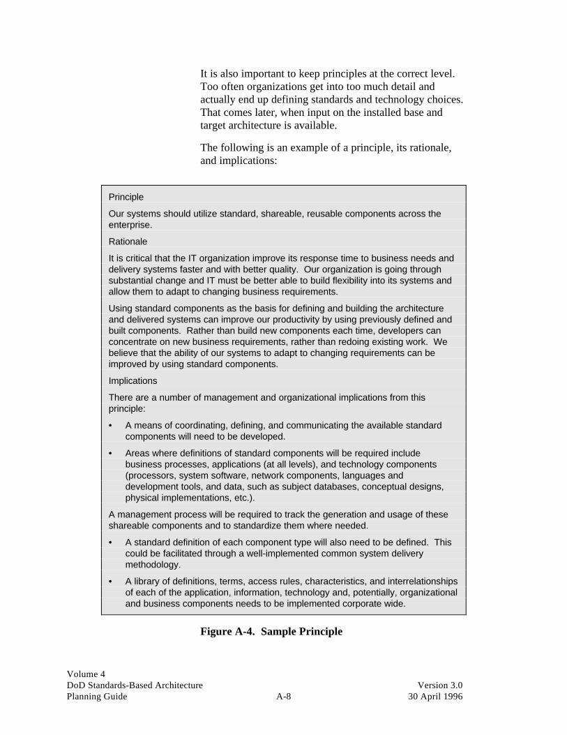
Volume 4DoD Standards-Based Architecture Version 3.0Planning Guide A-8 30 April 1996
It is also important to keep principles at the correct level.Too often organizations get into too much detail andactually end up defining standards and technology choices.That comes later, when input on the installed base andtarget architecture is available.
The following is an example of a principle, its rationale,and implications:
Principle
Our systems should utilize standard, shareable, reusable components across theenterprise.
Rationale
It is critical that the IT organization improve its response time to business needs anddelivery systems faster and with better quality. Our organization is going throughsubstantial change and IT must be better able to build flexibility into its systems andallow them to adapt to changing business requirements.
Using standard components as the basis for defining and building the architectureand delivered systems can improve our productivity by using previously defined andbuilt components. Rather than build new components each time, developers canconcentrate on new business requirements, rather than redoing existing work. Webelieve that the ability of our systems to adapt to changing requirements can beimproved by using standard components.
Implications
There are a number of management and organizational implications from thisprinciple:
• A means of coordinating, defining, and communicating the available standardcomponents will need to be developed.
• Areas where definitions of standard components will be required includebusiness processes, applications (at all levels), and technology components(processors, system software, network components, languages anddevelopment tools, and data, such as subject databases, conceptual designs,physical implementations, etc.).
A management process will be required to track the generation and usage of theseshareable components and to standardize them where needed.
• A standard definition of each component type will also need to be defined. Thiscould be facilitated through a well-implemented common system deliverymethodology.
• A library of definitions, terms, access rules, characteristics, and interrelationshipsof each of the application, information, technology and, potentially, organizationaland business components needs to be implemented corporate wide.
Figure A-4. Sample Principle

Volume 4DoD Standards-Based Architecture Version 3.0Planning Guide A-9 30 April 1996
Meat-principles Meat-principles are principles that apply to the ITenvironment as a whole. They address the organization’sposition on architecture, migration, and risk management,as well as its orientation to open or proprietary systems.
Architecture focus andcompliance
Organizations have different views regarding how muchthey are willing to spend for an architecturally compliantenvironment. Some organizations believe that the potentialadditional cost of architectural compliance outweighsincreased short-term costs. In other cases, cost pressures ora shorter-term view of benefits will reduce the impact of an“architected” environment.
Systems and technology infrastructure implemented by ourorganization will be compliant with our architecture even though
there may be an additional cost for architectural compliance.
Agree DisagreeImplications
• Faster migration to new infrastructure • Slow migration—probably will notimplement architecture
• Longer-term view of benefits • Shorter-term view
• Lessened dependence upon existinginstalled base of hardware/software
• Probably stay with existingvendor/product set—more orientedtoward existing proprietary systems
Cross-functionality Several organizations have seen the opportunity to reuseapplications, data, and related infrastructure in similar typefunctions across the organization. This requires a broaderview of the business and an understanding of how toidentify similar functions across the enterprise.
An orientation toward identifying and implementing cross-functional systems creates an opportunity for standards,standard components, and open systems. Technicalintegration opportunities are identified later on whendeveloping architectures based on such principles.Portability of applications and data become more importantso that similar systems and data can be implemented ondifferent platforms that may exist across the organization.A standard means of identifying, classifying, andspecifying system components is also required. Interface

Volume 4DoD Standards-Based Architecture Version 3.0Planning Guide A-10 30 April 1996
standards embodied in frameworks such as those outlinedin the CIM Technical Reference Model can form the basisfor interface and component specifications.
We will identify opportunities for cross-functional systems andimplement systems in such a way that we can take advantage of
standard components throughout the organization.
Agree DisagreeImplications
• Need to identify generic componentsand how they are implemented
• Organization likely has a strong line-of-business orientation with significantbusiness unit autonomy
• Standard application and datadefinitions are critical
• Potential problems with consolidation ofinformation across organization
• Planning, architecture, anddevelopment process needs toincorporate cross-functional review
• View that similar functions containenough differences that reuse ofstandard components would not bebeneficial (too much modification)
• Significant reuse of design, codepossible, but significant change in ITprocess, incentives and culture required
• Role for a “repository” of standardelements and their definition
Industry standards An organization’s position with regard to the source anduse of standards is a critical factor in its position withregard to open and proprietary systems.
Organizations that have completed a principles definitionprocess typically become favorably disposed toward usingindustry standards, especially if they have an orientationtoward reuse of system components and cross-functionalsystems. The perceived risk of continuing to be vendordependent is too high making the shift toward more open,industry standards appear less risky in the long run.

Volume 4DoD Standards-Based Architecture Version 3.0Planning Guide A-11 30 April 1996
Our standards and technology choices will be based on vendorneutral standards where available and implementable.
Agree DisagreeImplications
• Role for open systems standards andtechnologies
• Perception that industry standards arenot mature enough for use
• Development of standards and theirimplementation by vendors needs to becarefully tracked
• Focus more on a vendor’s productarchitecture—vendor-dependent suchas AS, NAS, etc.
• Migration strategies need to bedeveloped for utilizing industrystandards
• Organization unable to deal with migra-tion issue at present time or does notsee benefit of migration
• Focus on standards selection, thentechnology selection to supportstandards
• Limited set of vendors
• Need a mechanism for evaluatingproducts in terms of compliance tostandards and how to select productswhere standards have not been defined
• Evaluate organization’s industrystandards as well as IT industrystandards needed
Measurement While at first the issue of measurement would appear to beself-evident, the organization’s attitude and investment inmeasurement and metrics vary dramatically. Someorganizations view IT as delivering substantial businessvalue—the actual IT measurements may not be critical.Other organizations, especially ones focused on ITefficiency, may want to have explicit metrics of manyfacets of the IT environment and its impact on theorganization.
There are many measurement areas revolving around ITproductivity, efficiency, and quality. Some statement ofthe organization’s belief about measurement needs to bestated, as it will affect management processes aroundjustification and direct investment in measurementprograms.

Volume 4DoD Standards-Based Architecture Version 3.0Planning Guide A-12 30 April 1996
Applications and technology components (processors, network,etc.) need to be implemented in such a way thatmeasurement data can be captured for analysis
and management of the IT environment.
Agree DisagreeImplications
• Appropriate metrics and explicitindicators need to be established aswell as a management process forcollecting and managing themeasurement information
• View that IT provides intrinsic businessbenefits and the added cost forimplementing measurement capabilitiesare not justified
• Technology components need toprovide data about their operation andperformance
Efficiency vs. effectiveness Whether to focus on IT effectiveness or IT efficiency isclosely tied with the organization’s view ofmeasurement. IT effectiveness tends to focus on externalmeasures, ones that are often hard to quantify; theseinclude evaluating the business value of implementedsystems, the impact IT has on the organization’s marketshare, etc. Efficiency, on the other hand, focuses moreon internal measures such as productivity, cost control,processing efficiency, and transaction costs. Theorganization’s belief on this issue can indicate their viewof IT. Is IT a needed but unwanted expense, or is ITcritical to the organization’s success in its mission?
Information technology has a critical impact on ourorganization’s business success. We must focus on
improving IT’s impact on operations.
Agree DisagreeImplications
• IT viewed as a strategic asset • IT is viewed as a support organizationand not necessarily critical to theorganization’s mission
• External effectiveness measures critical • Internal efficiency and cost controlmeasures key
• Value focus—emphasis on increasingbusiness benefits of IT
• Cost focus—increased cost anddownsizing pressure on IT
• Probably more willing to take risks on ITinvestments
• Risk adverse

Volume 4DoD Standards-Based Architecture Version 3.0Planning Guide A-13 30 April 1996
Security A statement on security and contingency planning is needed if rolesand responsibilities are not defined or the policy is unclear. Whilethe need for secure systems can be considered “motherhood,” theorganization’s view of where and how security is implemented isimportant to state.
The following principle is one example of a security principle:
Implementation of security measures and contingency plans arethe responsibility of the business unit manager where the system is
implemented and must be “orange book” compliant.
Agree DisagreeImplications
• Decentralized approach to security • More centralization
• User managed security—IT plays anadvisory role
• IT is responsible for security
• Process needed to ensure adequatesecurity and contingency plans areimplemented by the business units
• Security can only be achieved throughcentral control
IT organization The IT organization principles deal with the organization’sview of how IT is organized and how it interacts with thebusiness. These principles will have an impact on thedegree of dispersion of IT and the role of a centralized(if any) IT organization.
Dispersion Dispersion deals with the degree of control and autonomythat business units have over IT decisions. In a highlydispersed organization, business units make essentially allthe IT decisions and may implement systems. In a non-dispersed organization, most IT-related decisions are madewithin the IT function.
Dispersion is different from centralization/decentralization.It is possible to have a decentralized IT function that is notdispersed. In this case, individual units may have theirown IT functions. On the other hand, in a centralized ITfunction with dispersed control, the IT function mayprovide resources or advice to the business units.

Volume 4DoD Standards-Based Architecture Version 3.0Planning Guide A-14 30 April 1996
Our IT organization will become increasingly dispersed into theoperational units but policy will be made centrally.
Agree DisagreeImplications
• Increasing control will migrate to thebusiness units
• Centralized management of IT
• Diminishing role and control for centralIT
• Linkages with business units have to bedefined and managed
• Standards become critical to ensurethat data can be shared and to limitpotential duplication of effort across theorganization
• Standards can be managed centrally
• Focus on “strategic” systems thatdirectly support the business unit
• Technology decentralization needs tobe addressed—likely increasedpressure for distributed computing
System ownership Management and ownership of implemented systems andtechnologies must be addressed to clarify roles andresponsibilities. This principle has a direct impact on therights and obligations of the business unit and IT managers.
Successful implementation and operation of information systemsand technology is the responsibility of the business and
operational unit(s) that the system supports.
Agree DisagreeImplications
• Responsibility for systemsimplementation is the business unitmanager’s
• IT likely responsible for successfulimplementation and realization ofbenefits
• Business unit managers mustunderstand how to successfully utilizeIT and manage implementation projects
Role of centralizedorganization
The role of the centralized organization is closely related tothe organization’s view of IT dispersion. In a highly

Volume 4DoD Standards-Based Architecture Version 3.0Planning Guide A-15 30 April 1996
dispersed environment, centralized IT may be responsibleonly for corporate financial and reporting systems andsome standards setting (as in the following example). Inother cases, the centralized IT organization may be a sourceof resources for business unit projects or, in the centralizedcase, be responsible for all IT functions.
The centralized IT organization will ensure that systems complywith our organization’s standards and will assist
organizations in IT.
Agree DisagreeImplications
• Standards setting, advisory, andcompliance verification role
• Implies either a limited role forcentralized IT or a highly centralized ITfunction
• Management processes needed todevelop and promulgate standards
• Standards and standards complianceperformed by centralized ITorganization
Life-cycle management Development, change management, and retirement ofsystems and technology infrastructure need to be managedon an ongoing basis. Architecture, and the systemsdeveloped from the architecture, must take into accountconstantly changing business needs and evolve with thebusiness.
Our systems should be developed in such a waythat they recognize the need for future changes to functional
and technology requirements even if the developmentcost is increased.
Agree DisagreeImplications
• Willing to accept additional cost to build andachieve easier maintenance and changemanagement
• Limited change to technology
• Acceptance of changing technology may implyneed for portability and portable environments
• Perceived to have stabletechnology base
• Increasingly shared and integrated systems willrequire adequate change-management facilities
• Standards less important
• Desire reduced maintenance cost and time
• Increasingly modular design to facilitate change

Volume 4DoD Standards-Based Architecture Version 3.0Planning Guide A-16 30 April 1996
Applicationmanagement
Application management principles deal with theorganization’s stated directions for managing applicationsand application components.
Depending upon the context for the architecture, theseprinciples can focus on structural system issues (portability,modularity, etc.), management issues (methods, techniques,distribution), or some combination of the two.
Taken as a whole, the application management principleshave to state the organization’s beliefs on “How will wedistribute and manage applications to get the maximumbenefit for the organization?”
Development processand methods
The role of a development methodology and associatedtechniques across an organization should be addressed.
Systems should be implemented using a consistentmethodology across the organization.
Agree DisagreeImplications
• Common development methodology • Methodology managed by individualbusiness units or departments
• Promotes sharing of techniques andlanguage
Reusability The issue of reusability of applications and applicationcomponents is analogous to many of the datastandardization efforts under way. Standard definitions ofbusiness functions and application components areaddressed in the following principle. This can be used toexpand the focus of reusability beyond sharing code tosharing business designs, documentation, etc. Potentially,investment could focus more on an expanded systemrepository or I-CASE tools.

Volume 4DoD Standards-Based Architecture Version 3.0Planning Guide A-17 30 April 1996
Applications should be developed using standard systemcomponents that are shared across the organization
Agree DisagreeImplications
• Standard definitions • High degree of customization required(possibly by business)
• Library of shared components needed • Limited cross-functional systems
• Components may be source code,application designs, documentation, etc.
• Migration to this environment needs tobe planned—promote activities thatprovide shareability
Build or purchase The make-versus-buy issue needs to be resolved.Organizations can swing either way on this principle,depending on their view of the uniqueness of their businessor applications.
Where possible we will purchase systems and components ofsystems by using commercial off-the-shelf (COTS) products
Agree DisagreeImplications
• Buy orientation • Tendency to build applications
• Procurement standards and processneed to be defined
• Development resources and standardscritical
• Cost of modification needs to beincorporated into package cost
Cross-functionalopportunities
Many organizations today have missed the opportunity toreuse portions of applications (see standard componentsprinciple above) by not identifying and architectingsystems that support similar functions in multiple areas.

Volume 4DoD Standards-Based Architecture Version 3.0Planning Guide A-18 30 April 1996
This represents a significant opportunity to improveproductivity and obtain some economies of scale throughfunctional or technical integration.
Applications should be developed so that they can be reused insimilar business functions across the organization
Agree DisagreeImplications
• Process needed to determine whatportions of an application are genericversus specific to the particularbusiness function
• Traditional design methods adequate
• Standard interfaces and standardcomponents needed
Distribution of applicationfunctions
Distributing application functions away from centralizeddata centers will have a significant impact on the resultingarchitectures and management processes required tomanage a distributed applications environment.
Application systems should be distributed and executed as closelyas possible to the users of the application.
Agree DisagreeImplications
• Decentralized, workstation focus • Centralized, host-processor focused
• Architecture levels (personal, workgroup, enterprise) need to be definedconsistent with the organizational levels
• Traditional application design anddevelopment environment
• Potential cooperative processingimplementation
• Economy of scale
• Potential multivendor implementationsof similar software
• Likely single or limited set of vendorplatforms
• Critical need for application environmentstandards

Volume 4DoD Standards-Based Architecture Version 3.0Planning Guide A-19 30 April 1996
Common applicationenvironments
A principle such as the one stated below supports a vendor-independent, portable environment. The result is a strongfocus toward open systems.
Applications should be developed in a common environment that isindependent of the underlying technology.
Agree DisagreeImplications
• Open systems needs to play a key role • Common environment may be singlevendor
• Multivendor, standards based—standards are key
• Open standards less important thanvendor products and standards
• Network computing standards required
• Architecture models must deal withcreating an “opaque” layer betweenapplication and technology
Common user interface The need for a common user interface (one with the samebehavior) has emerged as an important requirement inmany organizations. Common user interfaces (CUIs) canpotentially provide significant improvements inproductivity and training for users.
In the context of this principle, a common user interfacedoes not necessarily imply a graphic user interface thoughthe two seem to becoming synonymous with each other.The ability to customize the CUI for a particular need isoften important as a generic CUI may not provide the bestsolution in all cases. The issue of migration from existingcharacter terminals will need to be addressed, especially ifgraphic user interfaces are the chosen direction.

Volume 4DoD Standards-Based Architecture Version 3.0Planning Guide A-20 30 April 1996
Applications should present a common user interface that isadaptable and extendible to particular user requirements.
Agree DisagreeImplications
• Selection of an extendible common userinterface toolkit critical
• Application-specific interfaces
• Migration from existing workstation andterminal technologies need to beaddressed
• Easier migration—can utilize existinginstalled base
• Application design standards andprocurement standards need toincorporate CUI standard
• Purchasing software and hardware notrestricted by CUI
• Multivendor workstations and PCs mayneed to be accommodated
• Able to customize user interface tospecific applications
• Can integrate applications from varioussources more easily (from userperspective)
Informationmanagement
The organization’s approach to managing information isaddressed in the information management principles.
Multiform vs. single form The scope of the information managed and the degree ofintegration of different forms of information are addressedin the following sample principle.
Our architecture and implemented systems must addressthe management of all forms of information (data, text, voice,
image) in an integrated manner.
Agree DisagreeImplications
• Compound document standardsrequired
• Easier to implement today
• Information architecture needs toaddress all forms
• Oriented toward data and possibly textmanagement
• Tools and standards needed • Standards available

Volume 4DoD Standards-Based Architecture Version 3.0Planning Guide A-21 30 April 1996
Data standardization The organization’s view on data standardization needs tobe articulated. Is there a need for standard definitions? Isthe expense and effort justified? Is the organization sodecentralized that standardization efforts are not reallyworthwhile?
Standardization of data definitions and their implementation,access, interoperability, and communication is needed across theorganization to provide improved quality and consistency of data
and improve overall effectiveness of implemented systems.
Agree DisagreeImplications
• Standard definitions required • Limited communication acrossorganization
• Significant effort and cost associatedwith standardization effort
• Limited need or ability to consolidatedata
• Improvement in sharing andconsolidation of data
Ownership andstewardship
Ownership and stewardship of data needs to be addressedand agreed upon. This principle has a number ofimplications on how roles and responsibilities get defined.
Data is a corporate asset and does not belong to aparticular business unit or individual.
Agree DisagreeImplications
• “Corporate” ownership andmanagement of data
• Business unit management and controlof data
• Management of data may bedelegated—process is required toensure it is managed correctly
• Fragmentation of data a possibility—standards for consolidation andinterchange required

Volume 4DoD Standards-Based Architecture Version 3.0Planning Guide A-22 30 April 1996
Data access anddistribution
Like distribution of application function, distribution ofdata should be resolved. The organization’s view onapplication and data distribution helps determine its “style”of computing—centralized, decentralized, or somecombination of the two.
Data will be managed and stored as closely as possible to theperson/organizational unit who uses it.
Agree DisagreeImplications
• Distributed data management required • Data can be managed using existingtechnologies
• Degree of sharing needs to beestablished for data
• Accessibility of data by distributed usersneeds to be addressed
Technology management A wide variety of technology management principles canbe stated by an organization. Organizations often breaksuch principles down into key topic areas that deal with themajor components of the technology architecture(hardware, system software, communications, etc.).
It is important to articulate the role of each technologycomponent and the organization’s attitude towardmanaging vendors and technology. With the input fromthe application and information management principles, thetechnology management principles are where theorganization’s position toward open systems and standardsoften gets stated in black and white.
Interchangeablecomponents
The first principle addresses interchangeability of vendorproducts and services and, by implication, theorganization’s view toward open systems and standards.

Volume 4DoD Standards-Based Architecture Version 3.0Planning Guide A-23 30 April 1996
Some organizations view this principle (as stated) asunachievable in a reasonable time frame and choose a moreconservative approach.
We will implement technology components so that wehave the option of exchanging vendor products
with minimal disruption to the environment.
Agree DisagreeImplications
• Standards-based, open-systemsapproach
• Lock-in to a vendor
• Interfaces and environments need to bestandardized
• Can stay with existing technology baseor do a selective migration.
Vendor management An alternative statement of the following principle couldbe:
“We will limit the number of alternative vendors to alimited, manageable set” or “We are committed to asingle-vendor environment.”
We will utilize any vendor who provides us with the best technologyfor a business need.
Agree DisagreeImplications
• Need for standard environments tosupport multivendor
• Allowable vendor set needs to beestablished that can meet most needs
• Standard connectivity approachesneeded
• Limited set of vendors can bemanaged—build stronger relationships
• Portability of applications and data mustbe addressed

Volume 4DoD Standards-Based Architecture Version 3.0Planning Guide A-24 30 April 1996
Distribution ofprocessing capability
We will decentralize our processing environment so that individualbusiness units control their own computing resources.
Agree DisagreeImplications
• Promotes highly distributed environment • Promotes more centralized environment
• Remote management andstandardization critical
Role of intelligentworkstations
The following principle brings intelligent workstations(PCs, workstations) to the forefront as a platform fordelivering applications in the architecture.
The result is a highly distributed, processing environment.Applications and access to data would be provided throughthe workstation, supplemented by servers and hosts(minicomputers and/or mainframes) providing processingand data services to the workstations.
Intelligent workstations will be the primary access and deliveryvehicles for applications and data.
Agree DisagreeImplications
• Workstation, LAN orientation • Delivery through minis, mainframes
• Workstation standards and connectivitycritical—network computing needed tointegrate with other components
• Standards critical, but applications anddata less distributed
• Strong network computing role
Network connectivity The following three principles address networking issues.The first establishes the role of the common networkutility.

Volume 4DoD Standards-Based Architecture Version 3.0Planning Guide A-25 30 April 1996
We will use a common network environment usingindustry standards to interconnect all workstations,
computers, and communicating devices.
Agree DisagreeImplications
• Connectivity standards need to bedefined
• Autonomous computing/networkenvironments
• Full set of communications andtransport facilities will be required
• Tend to stay with host-basedcommunications—terminal to host
• Vendors need to supportinterconnectivity
• Can implement different networkingapproaches in different areas oforganization
• Integrated LAN/WAN/external networkdesign required
• Connectivity with customers/suppliersneeds to be addressed
• No system is an “island”
Network interfaces The following principle supports the premise that the“network is the computer” by placing the common networkenvironment as the core through which all devicescommunicate. Standard protocols and interfaces begin toestablish the need for a common interface standard.
The OSI model is often used to describe the variousinterface layers and as a framework for identifyingstandards.
All communicating devices must interface to the network through astandard set of protocols and interfaces.
Agree DisagreeImplications
• Limit direct connection of devices tocomputers—connect through commonnetwork
• Point-to-point links (e.g., computer toworkstation) allowed
• Migration from existing installed baseneeds to be addressed

Volume 4DoD Standards-Based Architecture Version 3.0Planning Guide A-26 30 April 1996
Network services The network’s role as a value-added service provider isestablished in the following principle. This represents abelief that value-added services can be delivered by thenetwork separately from the processors attached to thenetwork.
Common services such as file transfer, electronic mail, directorymanagement, and network management should be provided
through a common networking environment.
Agree DisagreeImplications
• Value-added applications need to beprovided
• Common services provided by hostprocessor
• Security of directories and servicesneed to be addressed
• May need to integrate different servicesat the workstation instead of through thenetwork
• Additional system managementservices should be examined
• Network-based processors for networkservices need to be defined
Conclusion The above-listed principles are but a few of the many thatan organization may seek to develop. We recommend thatall the existent CIM principles be incorporated into eacharchitecture effort.

Volume 4DoD Standards-Based Architecture Version 3.0Planning Guide B-1 30 April 1996
Appendix B: How To Do A BaselineCharacterization
General approach The baseline data collection effort is the first step indeveloping a useful baseline characterization of the currentarchitecture. Standard templates were developed over thecourse of the first SBA projects that were completed (or areunder way) at the time this update to the SBA Guide wasproduced.
The first section of this appendix presents these templates,along with the instructions that accompany them, andincludes a sample of a completed template from the USMCproject.
The second major section of this appendix providesguidance for the analysis of the information generated fromthe completed templates. General questions of interest and“rules of thumb” for analysts are provided.

Volume 4DoD Standards-Based Architecture Version 3.0Planning Guide B-2 30 April 1996
This page intentionally left blank.

Volume 4DoD Standards-Based Architecture Version 3.0Planning Guide B-3 30 April 1996
Baseline Data Collection
Work Organization Templates

Volume 4DoD Standards-Based Architecture Version 3.0Planning Guide B-4 30 April 1996
This page intentionally left blank.

Volume 4DoD Standards-Based Architecture Version 3.0Planning Guide B-5 30 April 1996
Business and Work Models Template
• Fill out one of these templates for each major business function in theenterprise
• See the Baseline Assessment Glossary of Terms for definitions
Mission • This is the organization’s mission:
Function • A major grouping of work for the enterprise:
Processes • Activities or job steps leading to a desired result within thefunction:
Location • Physical location(s) where work is performed:
Headcount This should also be entered on Baseline Template forFunction Costs.
Budget This should also be entered on Baseline Template forFunction Costs.

Volume 4DoD Standards-Based Architecture Version 3.0Planning Guide B-6 30 April 1996
Business Context Template
MarketForces
Suppliers
Other External Actors
Customers
Business Functions
* Fill in name of organization or business Unit:• Then fill in the boxes with appropriate information about your organization or business unit
Competed by:

Volume 4DoD Standards-Based Architecture Version 3.0Planning Guide B-7 30 April 1996
Business Context - Sample
COMBAT DEVELOPMENT COMMAND
MarketForces
ECONOMY
THREAT
INDUSTRIALBASE
TECHNOLOGYBASE
(Laboratories,Universities, etc.)
Other External Actors
CONGRESSDOS NCA
Business Functions
INTEGRATION/ASSESSMENT
REQUIREMENTSDETERMIN-
ATIONTRAINING
DOCTRINEDEVELOPMENT
CONCEPTS/PLANS
DEVELOPMENT
STUDIES/ANALYSIS
WARGAMINGSIMULATION
EDUCATION SECURITYASSISTANCE
Customers
SYSCOM FMF
SUPPORTINGESTABLISHMENT
RESERVEFORCES
Suppliers
PP&D
MC SYSCOM
OTHER SVCS.
MANPWR I&L
AVN R&P
NAVY
NSA DOD
DON JCS
UNIFIEDCOMMANDS
ALLIEDORGANIZATIONS
C4I
FDMC
FMF
CONTRACTORS
STATE DEPT.
HQMC
CINC

Volume 4DoD Standards-Based Architecture Version 3.0Planning Guide B-8 30 April 1996
This page intentionally left blank.

Volume 4DoD Standards-Based Architecture Version 3.0Planning Guide B-9 30 April 1996
Information Templates

Volume 4DoD Standards-Based Architecture Version 3.0Planning Guide B-10 30 April 1996
This page intentionally left blank.

Volume 4DoD Standards-Based Architecture Version 3.0Planning Guide B-11 30 April 1996
Baseline Template – Application to Information
Existing Application(s) Linked to Data Groups:
• List all known existing applications which support business functions within your organization in the left-most column of this matrix. (give common application abrreviation and full name if known)• List all known data groups across the top of the matrix, one per column. Attempt to list closely related data groups in adjoining columns under a larger heading called "Subject", i.e. the Subject will span one or more data group columns.• If more columns are needed repeat the applications on a second sheet and continue listing the domains and information subjects.• Place a C, R, U, and/or D in the intersection of the application and information subject to signify whether the application Creates, Reads, Updates, and/or Deletes the information subject as part of its functionality. Combinations are Possible.
This template should contain all data groupings and applications of the entire enterprise.
Subject
Data GroupApplication

Volume 4DoD Standards-Based Architecture Version 3.0Planning Guide B-12 30 April 1996
Baseline Template – Application to Information – Sample
Subject Customers Finished Products Supplier Transport Plant Equipment & Services & Facilities
Data Grouping Customer Business Orders Products Inventory Services Supplier Business Purchase Transport Transport Equipment FacilitiesApplication Information Agreement Information Agreement Order Acquisition Utilization
Planning Applications
New Product Concept and Planning System R CRUD R CRUD RExecutive Information System R R RProfit Planning System R R R R R R R R R R R R RStategic Planning System R R R R R R R R R R R R RProfitability Analysis and Reporting System R R R R R R R R R R R R RMarket Analysis and Trending System R R R RCapital Planning and Tracking System R R R R R R R R R R R R RPatent & License System CRUD CRUD R R CRUD CRUD
Selling Applications
Customer Business Agreement System CRUD CRUD R R R R R RSales Demand Forecasting System CRUD R R R RCall Reporting System CRUD CRUD R UD UDContract Versus Actual Reporting System CRUD CRUD R R RProduct Applications Technology System CRUD R R CRUD R RConsulting Service Tracking and Problem Resolution System CRUD R R R CRUD R RAdvertising and Promotion Scheduling and Information System R R RCredit Management System CRUD R R R R CRUD
Product and Services Delivery Applications
Order Management System CRUD R CRUD R R RComplaint Tracking and Resolution System CRUD R CRUD R R RCustomer Information System CRUD R R R R R R RFinished Product Inventory System R R CRUD R CRUDProduction Scheduling System R R R R CRUDAutomated Load Out System R CRUD R R CRUDTransport Scheduling and Optimization System R R R CRUD Fleet Maintenance and Inventory System R R R R R R CRUD CRUD CRUD Fleet Acquisition System R R R R R R CRUD R CRUD

Volume 4DoD Standards-Based Architecture Version 3.0Planning Guide B-13 30 April 1996
Database Inventory – TemplateInstructions:Fill in the requested information for databases and/or electronic files which support your area of operation. The following definitions of the columns apply:Database Name The commonly used name or acronym for the database or file (i.e. SASSY, MIMMS, TMS, etc.)Description A brief description of the contents of the database or file (i.e. personnel records, patient records, requisitions, etc.)Geographic Location The location where the database or file physically resides (i.e. the commonly accepted designation, such as city, base name, command name, etc.)Type The type of database or file system used (i.e. DOS file, dBase, Adabas, Oracle, Paradox, DB2, etc.)Platform The type of computer platform (i.e. PC, Workstation, Midrange, or Mainframe;
also state specific kind and model number if known, such as IBM PS/2, Sun Sparc Station, AS/400, DEC/VAX, IBM 3090, etc.)Additional Notes Any other clarifying notes which your feel will be helpful in characterizing the Database or File
Database Name Description Geographic Location(s) Type Platform Additional Notes
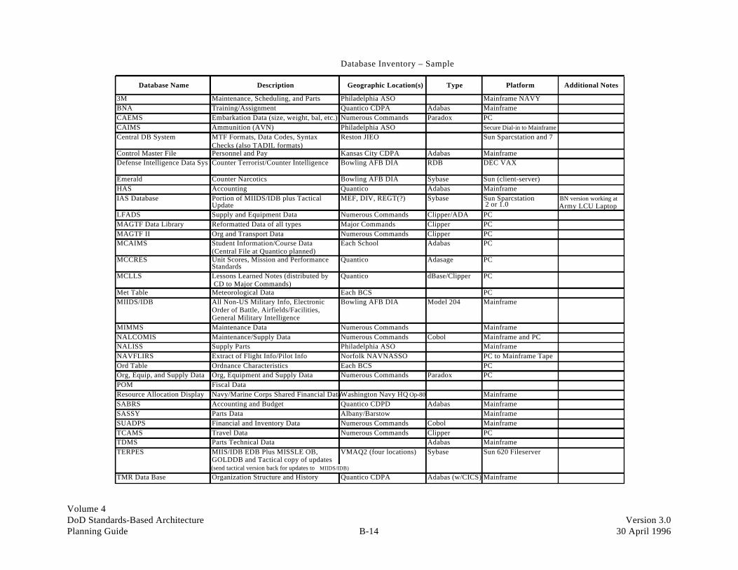
Volume 4DoD Standards-Based Architecture Version 3.0Planning Guide B-14 30 April 1996
Database Inventory – Sample
Database Name Description Geographic Location(s) Type Platform Additional Notes
3M Maintenance, Scheduling, and Parts Philadelphia ASO Mainframe NAVYBNA Training/Assignment Quantico CDPA Adabas MainframeCAEMS Embarkation Data (size, weight, bal, etc.) Numerous Commands Paradox PCCAIMS Ammunition (AVN) Philadelphia ASO Secure Dial-in to MainframeCentral DB System MTF Formats, Data Codes, Syntax
Checks (also TADIL formats)Reston JIEO Sun Sparcstation and 7
Control Master File Personnel and Pay Kansas City CDPA Adabas MainframeDefense Intelligence Data Sys Counter Terrorist/Counter Intelligence Bowling AFB DIA RDB DEC VAX
Emerald Counter Narcotics Bowling AFB DIA Sybase Sun (client-server)HAS Accounting Quantico Adabas MainframeIAS Database Portion of MIIDS/IDB plus Tactical
UpdateMEF, DIV, REGT(?) Sybase Sun Sparcstation
2 or 1.0BN version working at Army LCU Laptop
LFADS Supply and Equipment Data Numerous Commands Clipper/ADA PCMAGTF Data Library Reformatted Data of all types Major Commands Clipper PCMAGTF II Org and Transport Data Numerous Commands Clipper PCMCAIMS Student Information/Course Data
(Central File at Quantico planned)Each School Adabas PC
MCCRES Unit Scores, Mission and PerformanceStandards
Quantico Adasage PC
MCLLS Lessons Learned Notes (distributed by CD to Major Commands)
Quantico dBase/Clipper PC
Met Table Meteorological Data Each BCS PCMIIDS/IDB All Non-US Military Info, Electronic
Order of Battle, Airfields/Facilities,General Military Intelligence
Bowling AFB DIA Model 204 Mainframe
MIMMS Maintenance Data Numerous Commands MainframeNALCOMIS Maintenance/Supply Data Numerous Commands Cobol Mainframe and PCNALISS Supply Parts Philadelphia ASO MainframeNAVFLIRS Extract of Flight Info/Pilot Info Norfolk NAVNASSO PC to Mainframe TapeOrd Table Ordnance Characteristics Each BCS PCOrg, Equip, and Supply Data Org, Equipment and Supply Data Numerous Commands Paradox PCPOM Fiscal DataResource Allocation Display Navy/Marine Corps Shared Financial DataWashington Navy HQ Op-80 MainframeSABRS Accounting and Budget Quantico CDPD Adabas MainframeSASSY Parts Data Albany/Barstow MainframeSUADPS Financial and Inventory Data Numerous Commands Cobol MainframeTCAMS Travel Data Numerous Commands Clipper PCTDMS Parts Technical Data Adabas MainframeTERPES MIIS/IDB EDB Plus MISSLE OB,
GOLDDB and Tactical copy of updatesVMAQ2 (four locations) Sybase Sun 620 Fileserver
TMR Data Base Organization Structure and History Quantico CDPA Adabas (w/CICS) Mainframe(send tactical version back for updates to MIIDS/IDB)
Volume 4DoD Standards-Based Architecture Version 3.0Planning Guide B-15 30 April 1996
Application Templates

Volume 4DoD Standards-Based Architecture Version 3.0Planning Guide B-16 30 April 1996
This page intentionally left blank.

Volume 4DoD Standards-Based Architecture Version 3.0Planning Guide B-17 30 April 1996
Application Inventory – TemplateInstructions:Fill in the requested information for all applications which support your area of operation. The acronyms used on this template should also be used on any othertemplates which refer to application systems. The following definition of columns apply:Application Acronym The commonly used abbreviation for the applicationApplication Name The full English name of the applicationType Denote whether On-line, Batch, or Both On-line and Batch (“O”, “B”, or “OB”)Number Users The number of usersLanguage The language(s) the application is written inOperating System The Operating System and On-line Transaction Processing Monitor (if applicable) under which the application runsWhere Run: Specific Technology PlatformThe commonly used designation for the technology platform upon which this application runs
(i.e. the unique name for a particular processor and the basic vendor model information, such as “DAISY2, IBM3090 Model 600E”)
Where Run: Location of Platform The actual locations where the application runs on the platform identified in the prior columnAge The age of the application in yearsNumber Programs Number of executable programs in the applicationChanges Requested Number of change requests in past year; over entire historyChanges Implemented Number of change requests implemented in past year; over entire historyFailures Number of application failures in past year; over entire historyDeveloper What organization developed the applicationSupport What organization supports the application
Where Run
Specific LocationApplication Application Number Operating Technology of Number Changes Changes
Acronym Name Type Users Language System Platform Platform Age Programs Requested Implemented FailuresDeveloper Support

Volume 4DoD Standards-Based Architecture Version 3.0Planning Guide B-18 30 April 1996
Application Inventory – Sample
Where RunSpecific LocationApplication Application Number Operating
Technology of Number Changes Changes Acronym Name Type Users Language System Platform Platform Age Programs Requested Implemented Failures Developer Support
AB Automated BudgetABA Bonds & Allotments All MC COBOL II MVS-XA IBM, AMDAHL,
BURROUGHS, UNISYS, TANDEM
LEJEUNE, PENDLETON, OKINAWA, EL TORO, CHERRY PT., KANSAS CITY
22 159 27 27 KANSAS KANSAS
ABA Bonds & Allotments All MC COBOL II MVS-XA IBM, AMDAHL, BURROUGHS, UNISYS, TANDEM
LEJEUNE, PENDLETON, OKINAWA, EL TORO, CHERRY PT., KANSAS CITY
22 159 27 27 KANSAS KANSAS
ABE Application B Enhanced TACL GUARDIAN TANDEM CHERRY PT. 5 68 FMSO FMSO
ACIS Automated Claims Information System
MH Claims DBASE III MS-DOS PC HQMC 5 21 CONTRACT
AFRS Automated Fitness Report System
MMPE NATURAL MVS-XA IBM HQMC 20 216 270 270 0 QUANTICO QUANTICO
AIMS Awards information Management System
MH FORTRAN MS-DOS PC HQMC 4 200 CONTRACT
ALPS Automated Leave and Pay System
CIV PAY OFFICE, NAVCOMP, IRS
COBOL MVS-XA IBM, AMDAHL, BURROUGHS, UNISYS, TANDEM
QUANTICO, ALBANY, KANSAS, LEJEUNE, PENDLETON, OKINAWA, EL TORO, CHERRY PT.
23 85 92 89 1 QUANTICO QUANTICO
AMHS Automated Message Handling System
C/TOPIC UNIX DEC MEF, Garrison, CPs NEW DIA
AMMOLOGS Ammunitions Logistics System
COBOL MVS-XA IBM, AMDAHL, BURROUGHS, UNISYS, TANDEM
LEJEUNE, PENDLETON, OKINAWA, EL TORO, CHERRY PT., KINSER PARIS ISLAND
4 12 1 1 6 ALBANY ALBANY
AN/TPS-59 Radar Set 3D OL 15 Units CMS-2, ULTRA-32
AN/UYK-7 AIRWING 7
AOWP Automated Orders Writing Process
MMEA, MMOA, MMSR
COBOL II MVS-XA IBM QUANTICO, KANSASNCITY
13 55 33 31 3 KANSAS KANSAS
APADE Auto procurement TACL GUARDIAN TANDEM CHERRY PT. 3 1458 FMSO FMSO
APCS Automated Production Control System
NEW
ARMS Automated Recruit Management System
Recruiting COBOL II MVS-XA AMDAHL KANSAS CITY 15 675 11 11 0 KANSAS KANSAS
ASMS Advanced Shipping and Monitoring System
TACL GUARDIAN TANDEM CHERRY PT. 3 10 FMSO FMSO
ATAC+ (Maintained by the Navy)
ATRIMS Aviation Training & Readiness Information Management System
ALL FMF ADA MVS-XA IBM MC WIDE 8 1 QUANTICO QUANTICO
AV-3M/NAVFLIRS
Aviation Maintenance Material Management System Naval Flight Record
Aviation Units
COBOL II, ADA
MVS-XA, MS-DOS
IBM, AMDAHL, BURROUGHS, UNISYS, TANDEM, PC
LEJEUNE, PENDLETON, OKINAWA, EL TORO, CHERRY PT.
6 72 41 40 2 QUANTICO QUANTICO

Volume 4DoD Standards-Based Architecture Version 3.0Planning Guide B-19 30 April 1996
Application to Function – Template
Instructions:List all applications identified on the Application Inventory template in the left-most column of this template (give the common application abbreviation and full name if known).Major functions as identified in MHSS Technical Management Plan document are listed in the column headings.If there are other functions that your area performs which are not covered by these columns, list them in the blank columns.Place an "X" at the intersection of the row and column if the application in that row provides some automated information systems support to the business function represented by the column.
Function Health Care Health CareDelivery Delivery Health Care Human
Existing Application Clinical Preventative Management Financial Logistics Resources Information Research Education Liaison

Volume 4DoD Standards-Based Architecture Version 3.0Planning Guide B-20 30 April 1996
Application to Function – Sample
Function Command Doctrine Finance Human Intelligence Logistics Mainten-ance
Manpower Plans/ Policy Procure-ment Requirements Supply Training/ Transport Warfare/
& Control Services Concepts Education Operations/
Existing Application Combat Simulation
ABA XABA XABE XACISAFRSALPSAMHS XAMMOLOGS X XAN/TPS-59 RADAR XAOWPAPADE XAPCS XARMS XATAC+ATRIMS X XAV-3M/NAVFLIRS X XAWIS XAWNBASBCS XBCS XBNA X X XBNA X X XBNA X X X XBNA X X XBREES XBUDGETBUDS CLASS IICAEMS X X XCAEMS X X XCAIMSCAIS XCASPRO XCATS XCCS XCDCS X XCMIS X XCPMS XDAIS XDASCDCERPSDCIP XDDA XDE XDEERS IIB XDEERS IIIB XDEPMEDS X

Volume 4DoD Standards-Based Architecture Version 3.0Planning Guide B-21 30 April 1996
Application to Physical Location – Template
Instructions:List all applications identified on the Application Inventory template in the left-most column of this template (give common application abbreviation and full name if known).List all known physical locations where these applications may be accessed across the top of the matrix, one per column. If more columns are needed repeat the applications on a additional sheet(s) and continue listing the locations on those sheets.Place an "X" at the intersection of the row and column if the application in that row is accessed by at least one user at the location represented by the column.NOTE: Access to the application at a location does not necessarily mean the application is running on a computer at that location. It could be remote.
Physical Location
Existing Application
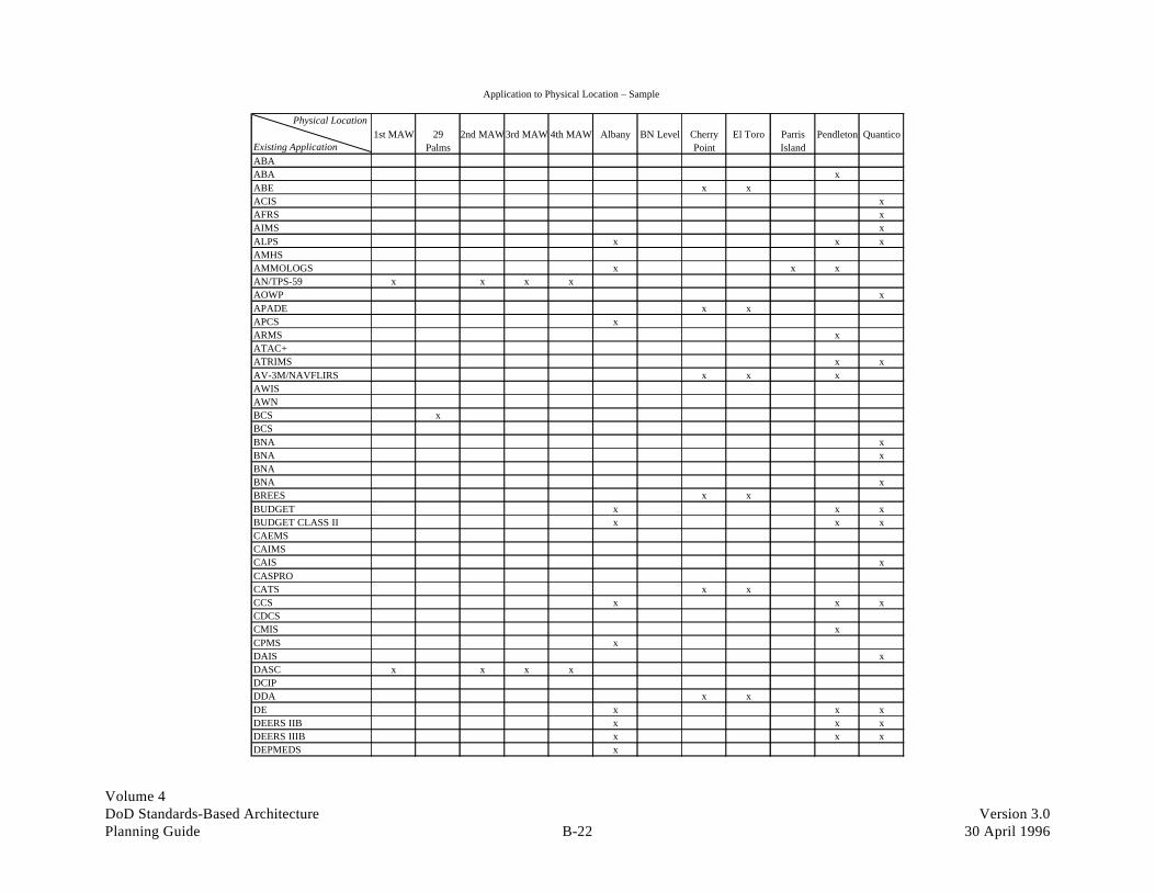
Volume 4DoD Standards-Based Architecture Version 3.0Planning Guide B-22 30 April 1996
Application to Physical Location – Sample
Physical Location
1st MAW 29 2nd MAW3rd MAW 4th MAW Albany BN Level Cherry El Toro Parris Pendleton QuanticoExisting Application Palms Point IslandABAABA xABE x xACIS xAFRS xAIMS xALPS x x xAMHSAMMOLOGS x x xAN/TPS-59 x x x xAOWP xAPADE x xAPCS xARMS xATAC+ATRIMS x xAV-3M/NAVFLIRS x x xAWISAWNBCS xBCSBNA xBNA xBNABNA xBREES x xBUDGET x x xBUDGET CLASS II x x xCAEMSCAIMSCAIS xCASPROCATS x xCCS x x xCDCSCMIS xCPMS xDAIS xDASC x x x xDCIPDDA x xDE x x xDEERS IIB x x xDEERS IIIB x x xDEPMEDS x

Volume 4DoD Standards-Based Architecture Version 3.0Planning Guide B-23 30 April 1996
Application to Standard – Template
Instructions:For all applications identified on the Application Inventory Template fill in the standards which are in use currently.
User Interface The software (or hardware) which "presents" the results of the application system's processing to the user (i.e. MS-Windows, 3270, Character Based, etc.)Include any online monitor software such as CICS or IMS/DC in this column as well.
Database The data base or file management software used by the application (i.e. Oracle, DB2, dBase IV, Adabas, VSAM, ISAM, etc.)Application Any self-contained "package" software which has been made an integral part of the application (i.e. Commander EIS, MS-Excel, Harvard Graphics, etc.)Language What the application code is written in (i.e. Cobol, Cobol II, C, C++, Pascal, ADA, etc.)Operating System The system software under which the application runs (i.e. MS-DOS, MVS-XA, DOS/VSE, OS/400, OS/2, UNIX System V, Xenix, etc.)Communications Media The transmission path for data communications (i.e. Marine Corps Data Network, Defense Data Network , Autodin, Token Ring, Arcnet, LocalTalk, etc.)Communications Protocol The protocol(s) used to control data communications related to this application (i.e. Banyan Vines, Novell Netware, SNP, SDLC, SNA, LU6.2, etc.)Other Services Any other aspects of the application which do not fall under any standards listed in prior columns
Standard User Interface Database Application Language Operating Commun. Commun. OtherSystem Media Protocol Services
Existing Application

Volume 4DoD Standards-Based Architecture Version 3.0Planning Guide B-24 30 April 1996
Application to Standard – Sample
Standard User Interface Database Application Language Operating Commun. Commun. Other
System Media Protocol Services
Existing Application
UADPS-WCSUTS-30 (Sperry Terminals) DMS 1100 Cobol EXEC (Univac) NAVNET SDLC
CATSDPS (Display
DMS 1100 Mapper EXEC (Univac) SDLC
DDAPC / 6530 (Tandem TACL Guardian SDLC / 3270
ABE TDI TACL Guardian Async / 6530
G-MAN PC / 3270 TACL Guardian
MDASPC / 6530 (Tandem TACL Guardian
NLN (Navy Logisitics Net) SDLC
RODS TACL Guardian
UADPS-SP PC / 3270 Cobol MCP (Burroughs)
MCCRES CICS DBaseIII ADA MS-DOS MCDN
SWIFTHAWK C MS-DOS
SORTS 3270 Adabase Cobol MS-DOS
MAGTF II Cobol MS-DOS WWMCCS
SASSY IA Cobol MS-DOS
MCLLS DBaseIII DBase / Clipper MS-DOS MCDN
TCAC Fortran MS-DOS VAF/UHF
EPOS 3270 Emulation PC Focus MS-DOS SNA SYS Bar Code
OCIS PC Focus MS-DOS
RPM/FHS Oracle SQL MS-DOS
MTF EDITOR Turbo Pascal MS-DOS
MIDAS (EIS) Redimaster MS-DOS Async
CMIS Harvard Graphics MS-DOS
AV-3M/NAVFLIRS CICS ADA / Cobol IIMS-DOS / MVS-XA TDI
ATRIMS CICS Adabase Ada MVS-XA MCDN
MCAIMS CICS Adabase C / Adabase MVS-XA MCDN
AMMOLOGS CICS/Natural Adabase Cobol MVS-XA MCDN
MEDLOGS CICS/Natural Adabase Cobol MVS-XA MCDN / Autodin
MIMMS IB CICS/Natural Adabase Cobol MVS-XA MCDN
JUMPS/MMS CICS / Natural Adabase Cobol MVS-XA MCDN SNA LU6.2
BUDGET Cobol II MVS-XATape / Disk Transfer
ATAC + MVS-XA Token Ring VINES
TMSCICS/Complete/ Natural Adabase Cobol / Natural
MVS-XA / MS-DOS MCDN
APADE
MCR (Borroughs Master Control program) TACL Pathway Token Ring VINES
PLRS CMS2Y SDEX / M UHFPLRS Interface Controller
PLRS PLRS Unique PLRS UniqueNavigator CMD & Control CMS-2 SDEX/M, SDEX/PLRS Unique PLRS Unique
NALISS CICS Natural SDLC / 3270
BCS TACFIRE S/W Comm. Wire TACFIRE S/W

Volume 4DoD Standards-Based Architecture Version 3.0Planning Guide B-25 30 April 1996
Low
High
High
High
1 2 31.5 2.5
1.5
2
2.5
3
User Satisfaction versus Strategic Value
STRATEGIC VALUE
USER
SATISFACTI
ON

Volume 4DoD Standards-Based Architecture Version 3.0Planning Guide B-26 30 April 1996
Low
High
High
High
1 2 31.5 2.5
1.5
2
2.5
3
User Satisfaction versus Strategic Value
USER
SATISFACTI
ON
STRATEGIC VALUE
LPCCSC
WSCCOB
MTCPAL
CCSFIS
NET CORNGROSS CORN
ACEBILDOE
CIS
GIN CDB
PDB
ARP
SI
FRSPCY
PSC
CAP
FUD MSI
AR-U
PER-P
GL-P
FP-P
AP-P
GA-P
CP-U
PAY-P
AP-U
GL-U
PUR-U
PUR-P
MASC-P RCMS-U
GP-U
NB-U
SF-U
CVA-U
OE-U
DEMUR-P
INV-P
PRICE-UBILL-U
EDI-U
OTHER PC-APPSACCOUNTING
OTHER PC-APPSPRODUCTION
OTHER PC-APPSPLANNING
BLMDRANETZRPB
EDSA VARIOUSCAD
CAD
DEXT
FPAINT TNBB
CAIRS RS1
ECAS
ENG
PC-DAILYSHIP,PC-WEEKLYSHIP
PC-PRICING
PC-PROD/SALES
PC-DAILYINV
Current Canadian applications Current US applications"-P" at end of application = Prime
"-U" at end of application name = HP-UX

Volume 4DoD Standards-Based Architecture Version 3.0Planning Guide B-27 30 April 1996
Low
High
High
High
1 2 31.5 2.5
1.5
2
2.5
3
Technical Quality versus Strategic Value
STRATEGIC VALUE
TECHNICAL QUAL I T Y

Volume 4DoD Standards-Based Architecture Version 3.0Planning Guide B-28 30 April 1996
Low
High
High
High
1 2 31.5 2.5
1.5
2
2.5
3
Technical Quality versus Strategic Value
TECHNICAL
QUALITY
STRATEGIC VALUE
ARPCSC
SIFIS
GIN CIS
MTCFRSCAPPALFUDLPC
PLYNET CORNGROSS CORN
PSC
CCS
WSC
MSI
CDBBILDOEACE
PDBCOB
PAY-PCP-UAP-UGL-UPUR-U
GA-PPUR-PFP-P
AP-PGL-PAR-U
PER-P
MASC-P GP-U
NB-USF-UCVA-U
EDI-U
INV-P
RCMS
DEMUR-P
OE-U
PRICE-UBILL-U
OTHER PC-APPSACCOUNTING
OTHER PC-APPSPRODUCTION OTHER PC-APPS
PLANNING
BLM
DRANETZ
RPB
EDSA
VARIOUSCAD
CAD
FPAINT
CAIRSDEXTTNBB
ENG
ECAS
RS1
PC-DAILYINV,PC-DAILYSHIP,PC-WEEKLY SHIPPC-PROD/SALES,PC-PRICING
Current Canadian applications Current US applications"-P" at end of application = Prime
"-U" at end of application name = HP-UX

Volume 4DoD Standards-Based Architecture Version 3.0Planning Guide B-29 30 April 1996
Low
High
High
High
1 2 31.5 2.5
1.5
2
2.5
3
Technical Quality versus Technical Evolution
TECHNICAL
QUALITY
TECHNICAL EVOLUTION

Volume 4DoD Standards-Based Architecture Version 3.0Planning Guide B-30 30 April 1996
Low
High
High
High
1 2 31.5 2.5
1.5
2
2.5
3
Technical Quality versus Technical Evolution
TECHNICAL
QUALITY
TECHNICAL EVOLUTION
GIN
MASC-P
SIFISCISARPCSC
CAPMTC
BIL,ACE,CCSWSC,PSC,COBFRS,MSI,DOE,PDB,PAL,CDBNETCORN,GROSSCORN,LPC,FUD,PCY
PER-P
AP-PGL-P
GA-P
INV-P
PUR-P
FP-P
DEMUR-P
PAY-P
GP-U
SF-U ,NB-U,AR-U
CVA-U
RCMS-U
EDI-U,BILL-U,OE-U,PRICE-U,CP-U,PUR-U,AP-U,GL-U,
MOST OTHERPC-APPS
BLM
DRANETZ
RPB
EDSA
VARIOUSCAD
CAD
DEXTRS1
FPAINT
TNBB
CAIRS
ECASENG
PC-DAILYINV,PC-DAILYSHIP,PC-WEEKLYSHIPPC-PROD/SALES,PC-PRICING
Current Canadian applications Current US applications"-P" at end of application = Prime
"-U" at end of application name = HP-UX

Volume 4DoD Standards-Based Architecture Version 3.0Planning Guide B-31 30 April 1996
Low
High
High
High
1 2 31.5 2.5
1.5
2
2.5
3
Summarized Application Assessment
U
S
E
R
S
A
T
I
S
F
A
C
T
I
O
N
STRATEGIC VALUE
T
E
C
H
N
I
C
A
L
Q
U
A
L
I
T
Y
TECHNICAL EVOLUTION
Keep / Tune
Replace / Discard
Asset / Build Upon
Renovate / Reengineer

Volume 4DoD Standards-Based Architecture Version 3.0Planning Guide B-32 30 April 1996
Low
High
High
High
1 2 31.5 2.5
1.5
2
2.5
3
Summarized Application Assessment
COMBINATION OFTECHNICAL EVOLUTION AND STRATEGIC VALUE
Keep / Tune
Replace / Discard
Asset / Build Upon
Renovate / Reengineer
Current Candian applications Current US applications
PER-P,MASC-P,
RPB,CAIRS,BLM,GL-P,AR-U,
DRANETZ
ECAS, EDI-U,OE-U, AP-U,
GL-U, PUR-U,CP-U, BILL-U,
PRICE-U, GA-P,AP-P, PAY-P,
DEMUR-P,OTHER PC APPS-ACCTG,OTHER PC APPS-PROD,OTHER PC APPS-PLNG
LPC, COB,GROSSCORN,
NETCORN,WSC
CAP, PAL, CCS,FUD, MSI, PSC,PCY, FRS, DOE,
BIL, ACE,GIN, PDB, CDB
MTC
SI, FIS,ARP, CSC
TNBB,RS1, RCMS-U,
RS1, ENG,FP-P,INV-P,PUR-P
FPAINT,VARIOUS-CAD,
CAD, ESDA,DEXT,
GP-U, NB-U,SF-U, CVA-U
CIS
PC-DAILYINV,PC-DAILYSHIP,PC-WEEKLYSHIPPC-PROD/SALES,PC-PRICING
"-P" at end of application = Prime
"-U" at end of application name = HP-UX
USER
SATISFACTION
TECHNICAL
QUALITY
AND
M
CO
BIATION
OF

Volume 4DoD Standards-Based Architecture Version 3.0Planning Guide B-33 30 April 1996
Technology Templates

Volume 4DoD Standards-Based Architecture Version 3.0Planning Guide B-34 30 April 1996
This page intentionally left blank.

Volume 4DoD Standards-Based Architecture Version 3.0Planning Guide B-35 30 April 1996
Personal Computer Workstation Inventory – Template
Instructions:Fill in the column headings with all known physical locations where Personal Computers and/or Workstations are in use.Place a quantity at the intersection of the row and column to depict the number of items in use at the physical location represented by the column.The following definition of rows apply:Number of Users The number of users who use or potentially could use the PCs and/or workstations as this locationIBM Compatibles The number of IBM PCs or Compatibles by CPU type (i.e. XT,286,386,486,586) in use at this locationOther The number of any other type of PC or Workstation (one row for each specific Vendor/Model) in use at this locationTotal PC's and/or Workstations The sum of the preceding rows, providing the total number of PCs and/or Workstations in use at this locationNumber Connected to LANs The number of PCs and/or Workstations which are connected to a Local Area Network at this locationNumber of LANs The number of discrete Local Area Networks in use at this location, without regard to whether these LANs are interconnectedNumber of LANs Connected to WANsThe number of Local Area Networks at this location which have connectivity to other remote locations via a Wide Area NetworkPC and/or Workstation Owner The Person and/or Organization with the budgetary ownership or responsibility for the PC's and/or Workstations at this locationPC and/or Workstation ManagerThe Person and/or Organization with the day-to-day operations responsibility for the PC's and/or Workstations at this location
Physical Locations
Inventory Item:
Number of UsersIBM Compatibles
XT286386486586
Others (list Vendor/Models below)
Total PCs and/or WorkstationsNumber Connected to LANsNumber of LANsNumber of LANs Connected to WANsPC and/or Workstation OwnerPC and/or Workstation Manager

Volume 4DoD Standards-Based Architecture Version 3.0Planning Guide B-36 30 April 1996
Personal Computer and Workstation – Sample
Physical Locations
29 Palms Camp Lejeune Camp Lejeune Camp Lejeune Camp Lejeune Camp Pendleton Camp Pendleton Camp Pendleton Camp Pendleton Camp PendletonMCAGCC 2nd Div 2nd FSSG CG,MCB II MEF MCTSSA 1st Div 1st FSSG CG,MCB I MEF
Inventory Item
Number of Users
IBM Compatibles
XT 16 11 40 128 20 95 71 31 14
286 116 626 608 967 216 344 872 718 722 159
386 89 157 118 223 33 204 211 322 238 80
486 8 17 61 4 59 18 70 19
586
Others (List Vendor/Models Below)
Apple Macintosh 2 4 10 2 1
Total PCs and/or Workstations 231 811 827 1322 253 637 1196 1181 993 273
Number Connected to LANs 173 608 620 991 189 477 897 885 744 204
Number of LANs 22 17 20 32 12 10 33 52 70 25
Number of LANs Connected to WANs 22 14 16 32 8 10 29 44 70 20
PC and/or Workstation Owner RJE G6/ISMO G6/ISMO RASC G6/ISMO MARCOR G6/ISMO G6/ISMO RASC G6/ISMO
PC and/or Workstation Manager RJE G6/ISMO G6/ISMO RASC G6/ISMO MARCOR G6/ISMO G6/ISMO RASC G6/ISMO

Volume 4DoD Standards-Based Architecture Version 3.0Planning Guide B-37 30 April 1996
Standards to Platform – Template
Instructions:Describe the specific standards in place for your Information Technology Platforms in the categories depicted by the Generic Technology Platform names in each row.Fill in the column headings with the same Platform names used on the Technology Platform Inventory Template. This should be a unique identifier for the specific technology platform.At the intersection of the Generic Technology Platform and the Platform Name enter the specific standard which is in place on that platform.Where multiple platforms of the same type are used in a similar fashion, list the Platform Name once and the approximate number of units in parentheses (i.e. IBM-PC486 (150 units)).The following row definitions apply:User Interface The standard(s) which controls the presentation of the results of computer system processing to the user (i.e. MS-Windows, 3270, Character-based, etc.Operating System The standard(s) which controls the basic operation of the computing platform (i.e. MS-DOS, MVS-XA, DOS/VSE, OS/400, OS/2, UNIX System V, Xenix, etc.)Communications Management The standard(s) which controls the connectivity of this platform to others (i.e. Banyan Vines, Novell Netware, SNA, TCP/IP, SMP, SDLC, etc.)Data Base (and/or file) ManagementThe standard(s) which controls how the data is managed on the platform (i.e. DOS File System, dBase, Adabas, Oracle, Paradox, DB2, etc.)Transaction Monitor The standard(s) which controls the processing of online transactions (i.e. CICS, IMS-DC, TSO, CMS, etc.)Document Management The standard(s) which controls document creation, storage and retrieval for the platform (i.e. DISOSS, MS-Word, Word Perfect, Office Vision, etc.)Distribution Management The standard(s) which controls the distribution of user messages and/or files within this platform and to other interconnected platforms
(i.e. Vines Mail, Quickmail, Office Vision, DISOSS, etc.)Conferencing Management The standard(s) which controls the resources of the platform to allow computer conferencing, shared screen conferencing, etc.Development Services The standard(s) which controls the environment under which computer programs are developed and tested (i.e. compilers, toolkits, CASE tools, debugging aids, etc.)Repository Services The standard(s) which controls the metadata, and data which describes the overall information management environment
(i.e. IBM's MVS/Repository Manager, IMS-Data Dictionary, etc.)Notes Any additional notes which will help clarify the specific platform standards in place or planned for the near term
Platform Names
Standard
User InterfaceOperating SystemCommunications ManagementData Base (and/or file) ManagementTransaction MonitorDocument ManagementDistribution ManagementConferencing ManagementDevelopment ServicesRepository Services
Notes:

Volume 4DoD Standards-Based Architecture Version 3.0Planning Guide B-38 30 April 1996
Standards to Platform – Sample
Platform Names
Standard 286, 386, 486 Micro/PCs Network Servers (LAN) AS/400 (mini) Hewlett Packard 3000 (mini) Mid-Size Mainframe Large Mainframe
User Interface Various Proprietary S/W Various Proprietary S/W Proprietary S/W Proprietary S/W TSO TSO/ROSCOE/ CICS
Operating System MS-DOS Banyan Vines OS/400 MPEV - VDelta9 MVS/SP MVS-XA
Communications Management Enable/Pro Comm Vines NOS IBM 3270 Emulation NS-3000 VTAM
Data Base (and/or file) ManagementEnable/dBase IV SQL Compliant Turbo Image 3000 (now SQL) ADABASE
Transaction Monitor CICS
Document Management Enable Office Vision DISOSS
Distribution Management Vines Mail Program Office Vision DISOSS
Conferencing Management
Development Services ADA/Clipper Vines ToolKit RPG/Cobol HP-TRANSACT/Cobol ADA/Cobol/ Assembler
Repository Services Dictionary 3000 ADABASE
Notes: Within 6 months all "Mid-Sized Mainframe" systems will be replaced by "IDNX Boxes" & channel extended off the Marine Corps
Large Mainframe systems.
Exceptions: RJE Iwakuni JA
RJE Kaneohe HI
RJE CCDH, HQMC Washington DC

Volume 4DoD Standards-Based Architecture Version 3.0Planning Guide B-39 30 April 1996
Technology Inventory – Template
Instructions:Generic Technology Platforms are listed in the leftmost column as row identifiers. There are likely to be more than one specific instance of each of these Generic Technology Platforms,i.e. within workstation, we may have Various kinds of terminals (NOTE: PCs and other Intelligent Workstations should not be included on this template. They are covered on the Personal Computer and Workstation Inventory Template). We may have multiple Vendors (i.e. IBM, Teletype Corp, Hitachi, HP, etc.). Within each vendor there could be multiple models (i.e. IBM 3278, IBM 3279, TLX 178-2, etc.)And each of these unique non-intelligent workstations would have an "owner", i.e. the person or organization which has budgetary ownership or responsibility for these workstations.Enter one line for each unique combination of Platform Name, Vendor Name, Platform Model, and Platform Owner. Use additional pages if you exhaust the blank rows within a Generic Technology Platform section.Enter each physical location which can contain one or more of these technology platforms as column headings under the broad heading "Quantities by Physical Location".Enter the quantity of each specific Platform (as depicted by a unique combination of Platform Name, Vendor Name, Platform Model, and Platform Owner) in the intersection with the column depicting the physical location which houses the platform.Use additional pages if more columns are needed to depict physical locations.The Following definition of the Generic Technology Platforms apply:Workstation Any terminal device which is not a PC or Intelligent Workstation (i.e. "dumb" or single-purpose terminals which have not been included on the Personal Computer and Workstation Template)Output/Input Peripheral Platforms such as Laser Printers, Line Printers, Scanners, Card Readers, etc.Local Area Network (LAN)The hardware aspects of Local Area Networks such as Token Ring, Ethernet, LocalTalk, etc.LAN Server A platform which is used to run the LAN operating system and services. This could be a PC or a specialized server platform of any size.Wide Area Network (WAN)A device which provides long haul communications services, such as DISN, DDN, Telenet, Tymnet, etc.Network Interface DeviceA device which provide an interface between the network and the computer processor, such as Front-end processors like IBM 3705 and NCR Comten.Concentrator, Multiplexer,Devices such as routers, gateways, cluster controllers, etc., which allow the basic network resources to be effectively used for multiple purposes and devices at a various points in time.Switching DeviceTransmission Device Specialized devices which provide the transmission medium for information transfer, beyond the facilities identified earlier in the WAN category, such as VHF and SHF Radio and/or Satellite.Storage Device Devices which allow the storage and retrieval of information, such as Disk Drives, Tape Drives, Microfilm Processors, etc.Mid-Range Processor Processors which are larger than workstation or terminal devices both physically and in processing and peripheral controlling capability, but not of the large, mainframe class, i.e. AS/400, 4381, HP9000, etc.Large Processor The largest mainframe processing platforms such as IBM's 3090 Model 400E and Hitachi's 5890-600E. This would also include large massively parallel processors and/or vector based supercomputers.Image Processor Devices which are specifically devoted to the processing of digital images, such as Kodak's Komstar system.
Identifying Information Quantities by Physical LocationTechnology Platform Vendor Platform Platform
Platform Name Name Model OwnerWorkstation
Output/Input Peripheral
Local Area Network
LAN Server
Wide Area Network
Network Interface
Concentrator/ Multiplexer/ Switching
Transmission Device
Storage Devices
Mid-Range Processor
Large Processor
Image Processor

Volume 4DoD Standards-Based Architecture Version 3.0Planning Guide B-40 30 April 1996
Technology Inventory – Sample
Identifying Information Quantities by Physical Location29 Palms Albany BarstowBlount Camp Camp Camp Camp Camp Cherry El Toro
Technology Platform Vendor Platform Platform MCAGCC IRMD Island Foster Lejeune Lejeune Pendleton Pendleton Point RASCPlatform Name Name Model Owner FASC RASC FASC RASC RASC
Workstation Terminal HDS 3472-FC1 C4I, HQMCWorkstation Terminal HP 2392-A C4I, HQMC
Output/Input Peripheral Laser Printer IBM 3812-2 C4I, HQMCOutput/Input Peripheral Laser Printer Xerox 9700 C4I, HQMC 2
Local Area Network (LAN) 10 Base-T 10 Base-T RJE 29 Palms 22Local Area Network (LAN) Ethernet 3Com 1st. FSSG *N/A
LAN Server Banyan FS IBM 386/486 1st. FSSG *N/ALAN Server Banyan FS IBM 386/486 2nd. FSSG *N/A
Wide Area Network (WAN)MCDN USMC MCCTA, Quantico 1 1 1 1 1 1 1 1 1 1 1
Network Interface Device FEP Comten NCR 3690-DS C4I, HQMC 1Network Interface Device FEP Comten NCR5675 C4I, HQMC 1 1 1
Concentrator/ Multiplexer/ Switching Device
Digital Switch (Tactical)
Tactical AN/TTC-42 MEF
Concentrator/ Multiplexer/ Switching Device
Digital Switch (Tactical)
Tactical SB-3865 MEF
Transmission Device HF MUX- Radio Central (semi-mobile)
Tactical AN/TSC-120 (proposed)
MEF
Transmission Device VHF-Single Channel-Manpack Radio
Tactical AN/PRC-68 MEF
Storage Devices DASD Amdahl 62/6880 C4I, HQMC 7Storage Devices DASD HP 3937 C4I, HQMC
Mid-Range Processor Midrange HDS EX33 C4I, HQMCMid-Range Processor Midrange HP 3000-58 C4I, HQMC
Large Processor Mainframe Amdahl 5890-300E C4I, HQMCLarge Processor Mainframe Amdahl 5890-600E C4I, HQMC 1 1
Image System Komstar Kodak Model IV C4I, HQMC 1 2 1Image System Komstar Kodak Model VI C4I, HQMC

Volume 4DoD Standards-Based Architecture Version 3.0Planning Guide B-41 30 April 1996
Cost Templates

Volume 4DoD Standards-Based Architecture Version 3.0Planning Guide B-42 30 April 1996
This page intentionally left blank.

Volume 4DoD Standards-Based Architecture Version 3.0Planning Guide B-43 30 April 1996
Application System Costs – Template
Instructions: Fill in the column headings with the application acronyms which are represented on the Application Inventory Template. Use additional pages as needed.The leftmost column provides the cost categories for which we need actual costs or headcount related to each application system.At the intersection of a cost category and application system enter the costs (or headcount if the category relates to FTEs).If you share any of these categories with other organizations, allocate your proportionate share of support and place a note at the bottom of the template, explaining the rationale for your allocation.For example, if an outside contractor supplies a Help Desk with 25 Full Time Equivalents (FTEs) but you only use 4 of the total FTEs, record the 4 FTEs in the Support Service Contractors FTE Headcount.The following definitions apply to the cost categories:Hardware Processors, terminals, PCs, Workstations, Frontend Processors, Disk/Tape Drives, etc.Software Online Monitors, DBMS's, Compilers, Report Writers, Operating Systems, etc.Applications Commercial packages and custom-developed application systems which provide end-user functionalityMaintenance (Hardware) Maintenance costs on all of the aboveInternal Direct Support Staff costs directly associated with developing, maintaining and operating the above itemsSupport Service Contractors Supplemental staff beyond those listed for in-house staff shown aboveNetwork Includes owned/leased equipment, Public Switched Network, VAN's and other network servicesInternal FTE Headcount Internal full time equivalent headcountSupport Service Contractors (FTE Headcount) Full time equivalent headcount for supplemental staff beyond internal staff identified aboveOther Any other item not covered in above categories (please explain with a note)
Applications
Cost Categories
Hardware
Software
Applications
Maintenance (Hardware)Internal Direct Support
Support Service Contractors (Cost)
Network
Internal FTE Headcount
Support Service Contractors (FTE Headcount)
Other
Total Costs
Notes:

Volume 4DoD Standards-Based Architecture Version 3.0Planning Guide B-44 30 April 1996
Application System Costs – Sample
Applications
Cost Categories SASSY APCS MCFMIS RPM/FHS TCAIMS
Hardware 1,340K 4,450K 17K
Software 40K 100K 1,800K
Applications
Maintenance (Hardware) 170K
Internal Direct Support 1,650K 760K 70K 1,640K
Support Service Contractors (Cost) 2,400K 40K 1,260K 2,760K
Network
Internal FTE Headcount
Support Service Contractors (FTE Headcount)
Other
Total Costs 4,050K 80K 2,200K 7,750K 4,417K
Notes:

Volume 4DoD Standards-Based Architecture Version 3.0Planning Guide B-45 30 April 1996
Security Templates

Volume 4DoD Standards-Based Architecture Version 3.0Planning Guide B-46 30 April 1996
This page intentionally left blank.

Volume 4DoD Standards-Based Architecture Version 3.0Planning Guide B-47 30 April 1996
Baseline Template – Application to Security
Application to Security Level:
• Enter all Applications as identified on the Baseline Template for Application Inventory• Selected Security Classifications are across the top. If these need modification, please mark the headings approprpriately.• If other security classifications should be tracked, use blank column.• Enter an "x" in intersection of platform type and column to denote the presence of security at this level for this application.• If more columns are needed for additional security classifications or rows for additional applications, use a second sheet.• If there are specific exceptions or notes for clarification, enter the information in the space below the matrix.
This template should apply to all applications in the entire enterprise.
Security ClassificationTop Unclassified
Application Secret Secret Confidential Sensistive Unclassified
Additional Notes and Clarifications:

Volume 4DoD Standards-Based Architecture Version 3.0Planning Guide B-48 30 April 1996
Baseline Template – Location to Security
Location to Security Level:
• Enter all Physical Locations as identified on the Baseline Template for Business Functions and Work Organization• Selected Security Classifications are across the top. If these need modification, please mark the headings approprpriately.• If other security classifications should be tracked, use blank column.• Enter an "x" in intersection of platform type and column to denote the presence of security at this level for this work location.• If more columns are needed for additional security classifications or rows for additional locations, use a second sheet.• If there are specific exceptions or notes for clarification, enter the information in the space below the matrix.
This template should apply to all locations in the entire enterprise.
Security ClassificationTop Unclassified
Location Secret Secret Confidential Sensistive Unclassified
Additional Notes and Clarifications:

Volume 4DoD Standards-Based Architecture Version 3.0Planning Guide B-49 30 April 1996
Baseline Template – Platform to Security
Generic Technology Platforms to Security Level:
• Locations are listed in the left column, one per row.• Generic Technology Platforms are across the top• If another security classification should be noted, add it to the key and to the appropriate column(s)• Enter all applicable security classifications at the intersection of each row and column• If more rows are needed for additional locations, use a second sheet.• If there are specific exceptions or notes for clarification, enter the information in the space below the matrix.
This template should apply to all platforms in the entire enterprise.
Technology Workstation Output/Input Local Area LAN Wide Area Concentrator Storage Mid LargePlatforms Device Network Server Network /Multiplexer Devices Range Processors
(LAN) /Switching ProcessorsLocations
Additional Notes and Clarifications:Security Classification Key:TS = Top Secret S = SecretC = ConfidentialUS = Unclassified SensitveU = Unclassified

Volume 4DoD Standards-Based Architecture Version 3.0Planning Guide B-50 30 April 1996
Baseline Template – Process to Security
Process to Security Level:
• Enter all work processes as identified on the Baseline Template for Business Functions and Work Organization• Selected Security Classifications are across the top. If these need modification, please mark the headings approprpriately.• If other security classifications should be tracked, use blank column.• Enter an "x" in intersection of platform type and column to denote the presence of security at this level for the activities and outputs of this work process.• If more columns are needed for additional security classifications or rows for additional processes, use a second sheet.• If there are specific exceptions or notes for clarification, enter the information in the space below the matrix.
This template should apply to all processes in the entire enterprise.
Security ClassificationTop Unclassified
Work Process Secret Secret Confidential Sensistive Unclassified Location Misc.
Additional Notes and Clarifications:

Volume 4DoD Standards-Based Architecture Version 3.0Planning Guide B-51 30 April 1996
Questions of Interest and Rules of Thumb
for Baseline Analysis

Volume 4DoD Standards-Based Architecture Version 3.0Planning Guide B-52 30 April 1996
This page intentionally left blank.

Volume 4DoD Standards-Based Architecture Version 3.0Planning Guide B-53 30 April 1996
Connectivitycharacteristics
• What is the relationship of the current platform toother target platforms? Is there a client/serverrelationship in place? If so, detail the associatedplatform environments and describe theclient/server relationship.
• What are the characteristics of the logical links thatthe platform under review has to other platformswith which it is linked. Are the links based onpeer-to-peer relationships such as LU 6.2? From aterminal interface perspective, how does theterminal view the platform linkage?
• What are the characteristics of the physical linksthat the platform under review has to otherplatforms with which it is linked? Are the linksbatch or interactive in nature? Interactive tokenring or dial-up?
• What are the current characteristics of the existingplatform with regard to the capacity of the platformunder review—the number of transactionssupported, effective throughput per period of time,bandwidth required, etc.?
• What are the problems and opportunities related tocurrent connectivity attributes? Do they enable orinhibit platform performance? How do they relateto application, technology, or cost performance?
Standards support What standards does the existing platform support andwhich of the following services?
- User interface services
- Database services
- Operating system services
- Communication services
- Management services
- Languages
- Applications.

Volume 4DoD Standards-Based Architecture Version 3.0Planning Guide B-54 30 April 1996
• What interface standards does this platform supportfor all of the above (e.g. UNIX operating systemsupport for POSIX P 1003.1 for operating systeminterface standard)?
• What effect does the current suite of standards haveupon IT objectives? Are they enabling or hinderinggrowth and attainment of IT objectives?
• What are the costs of using these standards? Towhat degree are our current standards “open”?
• To what degree are our standards vendorindependent?
• What degrees of freedom do we have within ourcurrent standards as implemented in existingproducts or services?
• What is the nature of the standards supported? Arethey proprietary or open?
• Are they de facto or de jure standards?
• How stable are they? Have they been in place for 6to 24 months?
• Are they “developing” standards? If so, is thefuture standards path for this platform clear?
• To what degree does the existing platform eitherpromote or inhibit portability, scalability, orinteroperability?
Generic applicationenvironment support
• What generic application environments arecurrently supported on the existing platform?
• What are the logical linkages between existingGAEs?
• What are the problems and opportunities related tocurrent application environment attributes—application delivery, technology, or cost-relatedissues?
Generic technologyenvironment
• What are the existing generic technologycomponents that make up the existing environment?

Volume 4DoD Standards-Based Architecture Version 3.0Planning Guide B-55 30 April 1996
• What kinds of services are being supported byGTE?
• What classes of users are using which types ofGTEs?
• What set of services is supported by the existingtechnology platform under baseline review?
• What are the problems and opportunities related tocurrent generic technology attributes—application,technology, or cost-related? How mature are theseenvironments? Where will these new applicationsgo in the future?
GAE and GTErelationship: logical andphysical connectivity
One of the key aspects of platform attributes is howindividual platforms work together to “plug and play” in anoverall architecture. In a function, every platform has arelationship with all other platforms in the function, even ifthey are standalone by nature. A method is needed tocharacterize these logical and physical relationships as wellas their attendant costs in a simple visual manner. This isthe essence of an architecture.
The problem in most functions is that the various platformattributes have not been decoupled from the technologyitself and therefore do not lend themselves to a logicalcharacterization for architecture planning and analysis. Byexamining each of the platform attributes on a logical aswell as physical basis, we may develop an overall pictureof how various platforms relate to one another across afunction.
The following matrix demonstrates a typical three-tieredarchitecture in a hypothetical function composed of LAN-based work group computing, mid-range computers, andtraditional mainframe access. Each one of the points on thematrix (dark dots) may be thought of as the logicalconnectivity point between the two platforms. Byexamining the individual attributes of each of the twoplatforms connected by these two points, one may examinethe nature of platform connectivity. Indeed, using such amatrix, one may characterize a number of attributes in abaseline architecture:
• How GAEs are related between business unitsacross a function.

Volume 4DoD Standards-Based Architecture Version 3.0Planning Guide B-56 30 April 1996
• How GTEs are related between business unitsacross a function.
• What standards are in place across a function ordepartment.
• The physical or logical connectivity characteristicsacross a function as well as the relationship oneprocessing environment has with another. Forexample, the “client/server” model may beillustrated in this manner.
• The relative cost of a platform or set of platforms ina function or department.

Volume 4DoD Standards-Based Architecture Version 3.0Planning Guide B-57 30 April 1996
WS O/I Per.
LANLANServer WAN
Iterfce.
Con./Mux/Switching
StorageMid-Ran.
Proc.Large Proc.
WS
O/I Per.
LAN
LANServer
WAN
Iterfce.
Con./Mux/Switching
Storage
Mid-Ran.Proc.
Large Proc.
Figure B-1Physical or Logical Connectivity
Platform cost data • Direct hardware costs—purchase cost,depreciation or lease.
• Direct operating system software costs—purchase, cost, depreciation, or lease.

Volume 4DoD Standards-Based Architecture Version 3.0Planning Guide B-58 30 April 1996
• Maintenance and service costs—recurringoperational cases.
• Personnel costs—direct and indirect for bothhardware and software.
• Training costs—direct and indirect for hardwareand software.
• Application costs—direct and indirect includingsoftware licensing and maintenance as well as other“intangibles” related to work flow, businessprocedures, inventory turn rates, management “timevalue,” and general productivity. (This lastcategory will vary enormously depending upon howthe application costs are quantified.)
Typically, cost data are the most difficult types ofinformation to collect in an architecture assignment. Thereare many reasons for this including the fact that little usefulcost information is kept in the first place. Good cost datacan be very helpful, especially in justifying the migrationplan later on. When cost data are available, they should becollected by the team to incorporate in the baselinecharacterization and for use in migration planning in laterstages of the project. (see Appendix F for a full discussionof the business case cost analysis.)
Security evaluationcriteria
A key aspect of the baseline includes providing aclassification of the application and technology platformsusing the criteria and classification scheme described in theU.S. Department of Defense Trusted Computer SystemEvaluation Criteria [DOD 5200.28 STD, December 1985].The appendix includes an entire section of securityplanning considerations.
Rules of thumb for thebaseline characterization
Once the matrices have all been completed, the analysisphase can begin in earnest. A substantial amount of effortmust go into the analysis and interpretation of the baselinecharacterization to provide a solid platform for identifyingthe projects that will be required to move the enterprisefrom the baseline to the target architecture. The assessmentof applications is of particular interest, since this providesthe guidance that will be instrumental in improving theeffectiveness of the enterprise. An example of applicationassessment is provided below in light of the significant roleapplications play in any architecture.

Volume 4DoD Standards-Based Architecture Version 3.0Planning Guide B-59 30 April 1996
Baseline applicationassessment rules of thumb
To prioritize future application opportunities, anassessment of existing application systems is needed. Inthis way, the existing applications and their associatedassessment can be mapped to the target applicationopportunities. For example, if an envisioned targetapplication is of high strategic significance and the existingapplications which provide equivalent functionality areassessed as being in need of replacement, the targetapplication would be a high priority initiative in themigration and implementation planning phases. If there isno existing application and the other conditions describedabove for the target application were the same, the targetinitiative would be at an even higher priority.
This kind of analysis must be done for each target andexisting application in the enterprise. To make this work, ahigh-level assessment of the existing applications isneeded. The following provides some criteria that can beused for this process.
Templates should be provided to representatives of eachfunctional area affected by the architecture and supportingIT staff, and should be completed with their assessment ofany existing application systems with which they werefamiliar. Emphasis should be placed on doing themrelatively quickly, with a reasonable subset of theuser/developer community providing input. The intentionis to perform the assessment only at a macro level foroverall trends and conclusions. An example of such atemplate is shown below.
Categorizations The recipients should be asked to categorize (high,medium, and low within each category) each applicationaccording to the following criteria:
• User satisfaction
• Technical quality
• Strategic value
• Technical evolution.

Volume 4DoD Standards-Based Architecture Version 3.0Planning Guide B-60 30 April 1996
Low
High
High
High
1 2 31.5 2.5
1.5
2
2.5
3
User Satisfaction versus Strategic Value
USER
SATISFACTION
OCIS
MDS TDCC PLRS
GPS
SWIFTHAWK
TERPES
SS CC
AMHS
TPCS
IAS
TRSS
FYDP
ALPSSA BRSCAEMS
VI SOLDS
PONGO-1
NALOWRS
SORTS
ATAC
VA MOS C
WTI
AV-3M
CAIMS
TDMS
NALISS
SP OT
MCAIMSMCCRES
HASHAWK
MCLLSAMMOLOGS
MCCAT
MCFMIS
CCS RPM/FHS
EP OS
TOPSGME
CMIS
LAKES HEL
LMIS
MRPMIMMS
CDCS
DE
MAGTF I ITCAIMSMEWSS
MEDLOGS
STRAT
SE MS
SA SSYMUMMS
SI DS
MDSS
DASC
DAISDFS
RAPIDSDEERS
FSCAIS
MMAS
BCS
EPSMAP ERS
MCPSOADSSOPUSAI MS
DEPMEDS
MLP
MCPOM
CPMS
AOWPACISAFRS
ATRIMS TCAC
STRATEGIC VALUE
Figure B-2Template for User Satisfaction Versus Strategic Value of Existing Applications
User satisfaction User satisfaction is self explanatory. For the othercategories, the following definitions should be provided:
Technical quality This assessment criterion measures the application’srobustness and maintainability. It is a measure of whetherthe application is well written with easy-to-follow,structured code and sufficient program comments tofacilitate enhancements or maintenance. A high technicalquality application will have data definitions (or otherfrequently changed items) included in the code as tables orcopy members rather than hard coded within the programs.Similar logic will be coded once and referenced in othersections of the program or application rather thanphysically replicating. In general, a high level of technicalquality would be an application that already follows theprinciples of common interfaces and consistent definitionsthat forward-thinking organizations usually adopt duringthe architecture framework phase of the SBA.

Volume 4DoD Standards-Based Architecture Version 3.0Planning Guide B-61 30 April 1996
Strategic value This assessment criterion measures the application’simportance in achieving strategic objectives. This shouldbe assessed by users in the context of the strategic driversas defined in the business context phase of the project.
Upon receipt of the above assessments and after the targetarchitecture is developed, a fourth criterion for assessmentshould also be applied to the existing application portfolio–that of technical evolution.
Technical evolution This assessment criterion measures the application’spositioning to evolve effectively into the target architectureand to take advantage of envisioned advances ininformation technology. For example, an application thatis written for a hardware environment and language thatwill become part of the target technology architecturewould normally have a higher technology evolution ratingthan one that is written for an environment that will not becarried forward into the target environment. Likewise, anapplication that is written in a “portable” language has ahigher evolution rating.
Based on the analysis of this data, a summarizedassessment can then be developed. These criteria shouldnow be mapped in the following pairs on four-quadrantmatrices to allow a high-level determination of therecommended disposition of each application:
• User satisfaction versus Strategic Value
• Technical Quality versus Strategic Value
• Technical Quality versus Technical Evolution.
The combination of this information can be used togenerate a summary assessment similar to the examplepresented below.
For this summary matrix, each application has beenclassified by placing it in the quadrant that mostappropriately represents the combined classifications, alsotaking into account the likely recommended disposition ofexisting hardware and system software platforms thatcurrently support the applications (i.e., the likely “technicalevolutionary” capability of the hardware/systems softwareplatforms themselves).

Volume 4DoD Standards-Based Architecture Version 3.0Planning Guide B-62 30 April 1996
Low
High
High
High
1 2 31.5 2.5
1.5
2
2.5
3
Summarized Application Assessment
USER
SATISFACTI
ON
STRATEGIC VALUE
TECHNICAL
QUALITY
TECHNICAL EVOLUTION
Keep / Tune
Replace / Discard
Asset / Build Upon
Renovate / Reengineer
CCSEPOSFYDPGME
MCFMISOCIS
RPM/FHSTO PSWSS
DECDCSCMISDAIS
DEERSDFS
LAKES HELLM ISMRP
MIMMSRAPIDSSPOT
SWI FTHAWK
ABACISAFRSALPSAMHS
AMMOL OGSAOWPARMS
ATRIMSAUTO-O PS
AV- 3MBCSBNA
AIMSATACDASC
DEPM EDSEPS
FSCAISMAPERSMCCATMCPS
MCPOMMDSS
MEDLOGSML P
MMASMUMMS
REMMPSSABRSTCAIMSTDCCTDM S
TERPESTMRITL
TPCSTPS-59TRSS
TYQ-23WTIVIS
CAEM SCAIMSCPMSDASCGPSHAS
HAWKIAS
JUMPS/MMSMAGTF II
MAPSMCAIMS
NALOOADSSOPUSPREPASSASSYSEM SSIDSSORTSSSCCSTRATTCACTYQ- 2TF PMVAM OSCWRS
MCCRESMCICISMCLL SMDSMEWSSML PMT F- EDITORNALISSNET-M GMTOLDSPLRSPONGO-1
Figure B-3Sample Summarized Application Assessment
The individual source matrices are typically completed byboth users and IS staff within multiple functional areaswith input from the client core AWG.
For the summary matrix, each application is classified in aquadrant that most appropriately represents the combinedclassifications from the source matrices. The followingprovides a bit more detail on each of these assessmentquadrants.
Replace or discard The application has low user satisfaction, technical quality,technical evolution, and strategic value. If the applicationis absolutely necessary to the business, it should becompletely replaced with a newly developed application orpurchased package.
Renovate/reengineer The application has low user satisfaction and technicalquality but high strategic value and operates in a technicalenvironment that can evolve into the target architecturerelatively effectively. The application might be given arevamped user interface for improved usability or maybethe programs can be restructured for better reliability andmaintainability, perhaps utilizing some reverse engineeringtools.

Volume 4DoD Standards-Based Architecture Version 3.0Planning Guide B-63 30 April 1996
Keep/tune The application has high user satisfaction and hightechnical quality but low strategic value and is written in anenvironment that will be difficult to evolve into the targetarchitecture. Because the application is technically soundand the users seem satisfied currently, keep the applicationas is for now doing minimal tuning and maintenance tokeep it running.
As it reaches the end of its normal life cycle, or as otherapplications in the new environment have an increasingneed to integrate with this application, it may have to bereplaced. However, because it is stable and has lowstrategic value, it should be one of the last applications tobe redeveloped or replaced.
Asset/build upon The application has high user satisfaction, technicalquality, and strategic value, and it operates in anenvironment that can evolve into the target architecturerelatively effectively. It should be retained as one of thecore applications upon which to build. Applications thatfall into the other three categories above should begin tomigrate into this category as they are redeveloped,replaced, or converted over the agreed-upon architectureimplementation interval.
Rules of thumb For this summary matrix, each application has beenclassified by placing it in the quadrant that mostappropriately represents the combined classifications, alsotaking into account the likely recommended disposition ofexisting hardware and system software platforms thatcurrently support the applications (i.e., the likely “technicalevolutionary” capability of the hardware/systems softwareplatforms themselves).
Because these ratings on the source matrices occurindependently, there is the potential for a given applicationto fall in different quadrants on each of the three sourcematrices (User Satisfaction versus Strategic Value,Technical Quality versus Strategic Value, TechnicalQuality versus Technical Evolution).
The following rules of thumb should be used in arriving atthe summary assessment when independent sources place agiven application in more than one quadrant or when thedefinitions of the quadrants themselves are insufficient tomake the determination:

Volume 4DoD Standards-Based Architecture Version 3.0Planning Guide B-64 30 April 1996
• The strategic value rating on the User Satisfactionversus Strategic Value matrix should be usedbecause this source matrix is completed by the usercommunity (rather than IS support staff). Theassumption is that the end user has the best feel forthe value of the application to the operational area itsupports.
• If an application has low technical quality and lowstrategic value and low technical evolutioncombined with high user satisfaction, theapplication is placed in the “keep/tune” quadrant(i.e., the high user satisfaction and low strategicvalue combination move the application to thekeep/tune rather than replace/discard). The user ishappy and it is not a strategic application so, for themoment, keep it going with minimal investment. Itwill be one of the later applications to be replacedin the new environment.
• If an application has high user satisfaction and hightechnical quality but low technical evolution andlow strategic value, it should be placed in thereplace/discard quadrant.
• If an application has low user satisfaction and lowtechnical evolution but high strategic value andhigh technical quality, it should also be placed inthe replace/discard quadrant.
• If an application has high user satisfaction and highstrategic value but low technical evolution and lowtechnical quality, it should be placed in thekeep/tune quadrant. Over the long term it will needto be replaced because of the low evolution andquality ratings; however, it should not be replacedright away because the users like what they haveand it is important to the operation.
• If an application has low user satisfaction but rateshigh on technical quality, technical evolution, andstrategic value, it should be placed in therenovate/reengineer quadrant. The basicapplication is probably reasonable as a buildingblock, but perhaps it lacks critical functionality orthe user interface may be cumbersome. A facelift

Volume 4DoD Standards-Based Architecture Version 3.0Planning Guide B-65 30 April 1996
may be all that is needed to increase usersatisfaction.
• If an application rates high on user satisfaction,technical evolution, and strategic value but is ratedlow on technical quality, it should also be placed inthe renovate/reengineer quadrant. The lowtechnical quality is probably of the sort that is notvisible to the user, such as unexpected crashes orincorrect data returned. If it were, the usersatisfaction would probably not be high. Thereason for low technical quality ratings in this caseare probably due to difficulty in maintaining,debugging, and enhancing these systems due topoorly structured programs. Given the high usersatisfaction, this is an application that should bereengineered internally for more efficientmaintainability and execution while maintaining thelook and feel it has today.
• If an application is rated low on user satisfactionand technical evolution but high on technicalquality and strategic value, it should be placed inthe replace/discard quadrant. Regardless of howhigh the technical quality is in the currentenvironment, if the environment will not be carriedforward into the target, the ultimate fate of thisapplication is to be replaced or discarded,depending on the strategic value. In this case,where the application is strategic, the choice will beto replace it with an application that functions in thetarget technical environment.
• If an application has low user satisfaction, technicalquality, and technical evolution but has highstrategic value to the enterprise, it should be placedin the replace/discard quadrant. As in the caseabove, the lack of evolution capability alone isenough to place it in this category. This, coupledwith low technical quality in the currentenvironment, provides two compelling reasons tobuild a new application to support this strategicallyimportant functionality.
• Finally, some judgment calls will need to be madewhere applications end up near the borderline of

Volume 4DoD Standards-Based Architecture Version 3.0Planning Guide B-66 30 April 1996
two or more quadrants. In these cases, lowtechnical evolution ratings should generally pullapplications having high strategic value into thereplace/discard quadrant.

Volume 4DoD Standards-Based Architecture Version 3.0Planning Guide C-1 30 April 1996
Appendix C: Detailing the TargetArchitecture
Most efforts at detailing a target architecture tend to settle ona three-tier model of computing. Each of these tiers isdetailed below.
Enterprise tier It is envisioned that some systems will support virtually allfunctional areas. In fact, these systems will haveenterprise-wide impact through the data they capture andmake accessible to users. They will reside at a minimumnumber of locations (usually only one, but certainly onlyone within each major area of operation).
These enterprise-wide systems support operations that arecommon to all work groups. Also, the kind of activitiessupported do not typically require split-second responsetimes and real-time currency of information, although thismay be desirable. The key aspect of systems falling into thisclassification is that they typically process large volumes ofinformation, and this information needs to be accessed in aconsistent way by many users who are usuallygeographically and organizationally dispersed.
The technology architecture will provide for computerprocessing to support the enterprise-level systems in acentral location(s) with appropriate disaster recovery andsecurity capabilities. All users will be able to access thesefacilities via network connections.
These systems will probably be positioned to run on high-capacity processors (depending on data volume, responsetime requirements, etc.). The final decision will be madewhen the detailed design of the specific application system isundertaken.
Work group A work group is composed of individuals who sharecommon requirements and needs for information access toperform their function. There are typically multiple workgroups within the organization. They typically have a needfor quick access to current, function-specific information.

Volume 4DoD Standards-Based Architecture Version 3.0Planning Guide C-2 30 April 1996
The technology architecture will provide for computerprocessing in close proximity to the work group to supportthese quick access requirements. Work group level systemswill be deployed to physical locations that support a criticalmass of individuals within a work group. Therefore, workgroup systems may be replicated over the networkcomputing environment.
Within the work group classification will be multiplespecialized, but interconnected servers, specificallyapplication servers, communications servers, data servers,etc. These processors will support each individualworkstation’s need for access to work group data andconnectivity to other servers beyond the immediate workgroup, as well as the enterprise processor(s) that house theenterprise applications.
Individual The individual level of architecture is the individual workerequipped with a computing platform that is networked toallow access to work group and enterprise facilities.Application systems deployed at the individual level fallinto two categories: supporting “tools,” such as E-mail,word processing, spreadsheets, and calendaring/schedulingtools; and the “client” portion of work group or enterprisesystems, which allow access to data and services that resideon enterprise and work group computing levels. Thesetypes of systems may be made available on an individual’sworkstation to allow maximum customization andautonomy while allowing continued connectivity to otherwork group and enterprise systems via the network.
Within the work group and individual levels there are furtherclassifications:
Transportable This is the case of the work group level of computingwhere one or more work groups are physically transportedto a temporary base operation but, once there, they remainfixed for a period of time. An example would be adeployed medical treatment facility in temporary quarters.
Mobile This is a special case of the work group and individuallevels of computing where one or more work groups andindividuals are “on the move” and require access toindividual, work group, and enterprise computing resourceswhile mobile.

Volume 4DoD Standards-Based Architecture Version 3.0Planning Guide C-3 30 April 1996
Each level of computing has some unique characteristics interms of the topology and the components needed to makeup the total computing environment at that level. Thefollowing is a graphic depiction of each level and how it willinteroperate.
To support the location profiles discussed above, thetechnology architecture has taken the form of a three-tierednetwork computing environment. This environmentprovides maximum flexibility to support both common andunique local applications while providing the connectivityrequired for information sharing. This architecture alsoprovides a measure of local control over systems operationfor the various work group locations by allowing criticalapplications to be co-located with the local work group staff.The three tiers of the target network computing environmentare:
Local area networks A local area networks (LAN) provides terminal and/orworkstation access to individual, work group, or enterprisecomputing resources as well as file sharing and peripheralsharing. The LAN also provides communication withmembers of the local work group via electronic mail, localoffice automation tools, and simple localized applicationsystems, which run either on the workstations themselvesor on LAN-based processors (referred to as “LANservers”). The LAN will always provide the link to othernetwork components that, in turn, will link to computerprocessors. There are exceptions only in cases of deployedmobile computing at the individual level where LANconnectivity is not feasible.
Campus area networks A campus area networks (CAN) interconnects LANs withina physical work location (or “campus”). Each major fixedphysical location will have a single CAN as a “backbone.”These fixed physical locations would typically be inCONUS or host facilities that have been provided for long-term usage. CANs will support higher speeds than LANsfor rapid message and file transfer between loosely coupledapplications that run on multiple work group processors(work group servers) at a physical location or that run onLAN servers as described above.
Workstations and/or terminals will never directly connectto the CAN. These devices will gain access to the CANonly via their LAN connection.
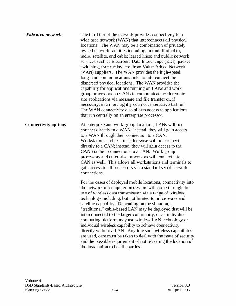
Volume 4DoD Standards-Based Architecture Version 3.0Planning Guide C-4 30 April 1996
Wide area network The third tier of the network provides connectivity to awide area network (WAN) that interconnects all physicallocations. The WAN may be a combination of privatelyowned network facilities including, but not limited to,radio, satellite, and cable; leased lines; and public networkservices such as Electronic Data Interchange (EDI), packetswitching, frame relay, etc. from Value-Added Network(VAN) suppliers. The WAN provides the high-speed,long-haul communications links to interconnect thedispersed physical locations. The WAN provides thecapability for applications running on LANs and workgroup processors on CANs to communicate with remotesite applications via message and file transfer or, ifnecessary, in a more tightly coupled, interactive fashion.The WAN connectivity also allows access to applicationsthat run centrally on an enterprise processor.
Connectivity options At enterprise and work group locations, LANs will notconnect directly to a WAN; instead, they will gain accessto a WAN through their connection to a CAN.Workstations and terminals likewise will not connectdirectly to a CAN; instead, they will gain access to theCAN via their connections to a LAN. Work groupprocessors and enterprise processors will connect into aCAN as well. This allows all workstations and terminals togain access to all processors via a standard set of networkconnections.
For the cases of deployed mobile locations, connectivity intothe network of computer processors will come through theuse of wireless data transmission via a range of wirelesstechnology including, but not limited to, microwave andsatellite capability. Depending on the situation, a“traditional” cable-based LAN may be deployed that will beinterconnected to the larger community, or an individualcomputing platform may use wireless LAN technology orindividual wireless capability to achieve connectivitydirectly without a LAN. Anytime such wireless capabilitiesare used, care must be taken to deal with the issue of securityand the possible requirement of not revealing the location ofthe installation to hostile parties.

Volume 4DoD Standards-Based Architecture Version 3.0Planning Guide C-5 30 April 1996
Why this computingapproach?
This network computing approach with distributedapplications and data minimizes the impact of network orprocessor failure on the enterprise (i.e., the failure of onepart of the network), or a local computer will not bring allwork group systems down. Also, backup and recovery ofthe work group that has had the failure can beaccomplished by switching it, with minimal disruption, toone or more of the other distributed platforms, if thenetwork connectivity remains intact.
The network computing approach also provides theinfrastructure and connectivity required to easily supportcommon services such as E-mail and EDI. These commonservices have been defined as a required part of manyapplication systems of the future and will be a key enabler toeffective information capture and sharing.
Finally, the network computing approach will enable theorganization to take advantage of emerging “groupware”packages that allow common work activities to be moreeffectively automated. Common office automation tools,such as word processing, calendaring, and business graphics,are all more effectively implemented and managed in anenvironment where connectivity is assured. These workgroup and individual productivity tools fit naturally onLAN-based platforms. A measure of standardization onthese tools and platforms will be necessary for theorganization to reap the productivity and effectiveness gainsit seeks in the coming years. The network environment willfacilitate this process.
Questions to considerwhen detailing thearchitecture
There are a number of questions the AWG should ask itselfwhen working through standards at each layer of the DoDreference model. While this is not intended to be an all-inclusive list, here are some questions that a work team canbegin to ask when developing the target architecture:
• What opportunities exist for application and technologyenvironment portability within our existing baselinearchitecture?
• Which of our existing standards meet these functionalityrequirements?

Volume 4DoD Standards-Based Architecture Version 3.0Planning Guide C-6 30 April 1996
• What is the impact of DoD standard systems on myfunctional area architecture?
• What gaps do we have in our standards? Which ones areneeded but do not exist? Which ones exist but haven’tbeen implemented in our organization? Why?
• What advantages could be derived through making ourcurrent architecture more “portable,” more “scalable,” orcapable of a higher degree of interoperability?
• What kind of benefits are these—cost savings or “value-added” (such as rapid response to wartime situations)?
• What are the “diversity costs” for operating multipleenvironments across the Logical Operating Unit (LOU)?
• What payoff does standards implementation afford ourorganization? When and where? What is the businesscase?
• What is the impact of Federally mandated standards onmy functional area’s architecture?
• Should we build standards within specific verticalapplications, or should we integrate them within specifictechnology platforms across the organization (e.g.,implement standards within a customer serviceapplication versus a specific platform area, such as userinterface, across the LOU)?
• How much of the existing embedded “legacy” system(s)do we keep? What needs to be replaced? What is the ITand business case for either solution?
• Can we implement these standards? Is the plan realistic?When will we achieve results? What time frameconsiderations merit review?
Key questions In addition to the general standards questions, there arespecific standards issues to be addressed at each level of thestandards-based model. The following questions arepresented solely as guidelines. These question sets shouldbe extended by the AWG in every area relevant to theenterprise’s architecture.
User interface • What are the user requirements for user interface (UI)across the functional area(s) with which I am working?

Volume 4DoD Standards-Based Architecture Version 3.0Planning Guide C-7 30 April 1996
• How global a UI do I want to put in place? Do I wantone or several?
• What UI standards do I want to adopt—the X/Windowsmodel, a proprietary-based implementation, or both?
• Will the UI(s) run on proprietary and “open system”workstations? Will they run on both POSIX-based andnon-POSIX–based workstations?
• What UI standards does my existing environmentsupport? Can I migrate my current UI environment intoa common standards-based set of UIs? How global a UIstandard do I want?
• What is the “diversity cost” of the set of UIs in place?Is there an opportunity to eliminate and simplify?
• Which de facto or de jure standards in this area can Imake use of now? How standards-compliant are myoptions?
• What role will my UI play in an overall client/serverstrategy or cooperative processing architecture?
• If I am not conducting true multiuser/multitaskinginteractive applications, what is the value ofimplementing a common UI?
• Is there a suite of “seamless” UI “shrink-wrapped”(commercially available) software available for these“standalone” workstation applications? Neither solutionoffers the advantages of a true proprietary (VAX, OS/2)or open system-like (POSIX) multitasking environment.
• Does this UI support true multitasking/multiuser workgroup requirements, or does it really only provide “taskswitching”?
• Do the UI products I am evaluating support the targetplatforms I am designing? How do they handleapplication binary interfaces?
• What will the total cost for my UI strategy be, includingcosts to upgrade workstations, LAN wiring,implementation, and retraining?
Database • What are the user requirements for database across the

Volume 4DoD Standards-Based Architecture Version 3.0Planning Guide C-8 30 April 1996
functional area(s) with which I am working?
• What is the “diversity cost” of this set of variousdatabases? Is there an opportunity to eliminate andsimplify?
• Which of the de facto or de jure standards in this areacan I make use of now? How standards-compliant aremy options?
• What is my overall database strategy and architecture?What is the outlook for relational database proliferation?How will functional area(s) handle database relatedactivities in the future?
• To what degree is my current database architecture SQLcompliant? To what degree should my targetarchitecture be SQL compliant?
Applications • What is the scope, depth, and number of the applicationportfolio across the functional area(s) with which I amworking?
• What is the “diversity cost” of this set of variousapplications? Is there an opportunity to eliminate andsimplify?
• What will I do with systems that are currently underdevelopment but may not be “playing by the standards” Iam proposing?
• Which of the existing applications described in thebaseline effort should be considered candidates for:
- Porting to a new open systems environment
- Recoding into a new environment
- Redesigning into a new environment
- Starting from scratch
- Killing and eliminating?
• How will the existing applications support our targetGAE and GTE requirements? How will they coexistwith new applications if they are not going to bereplaced? What is their life cycle?

Volume 4DoD Standards-Based Architecture Version 3.0Planning Guide C-9 30 April 1996
• Which applications are redundant? Which of the targetapplications could be modularly “reused”? Does thecode permit reusability?
• What standard programming languages does theapplication support? Do these languages map to mylanguage standards strategy?
• Are new target applications available in “shrink-wrap”form? What platforms do they currently support? Howdoes my existing and target architecture support theseproducts today and tomorrow?
• Are there de facto or de jure standards in this area I canuse now? How standards compliant will my targetoption be?
• What target tools will I use in the conversion process ifconversions are deemed necessary? What CASE-toolstandards should I use? Do they support evolving CASEstandards?
• Does my existing vendor offer porting services for thetarget application suite in the GAEs and GTEs I amdesigning? How will I handle conversion if they do not?
• How will new target applications support interfaces todatabases, user interfaces, languages, operating systems,communications, management services, and otherservices? Are there application portable interfaces forthese applications in place? What are they? Are theycompliant? Are they X/Open XPG compliant?
• What will be the total cost for my application strategy,including costs to migrate and retrain? What are thecosts and risks associated with migration?
Languages • What is the scope, depth, and number of languages inthe language portfolio across the functional area(s) withwhich I am working?
• Have I complied with the DoD policy regarding the useof ADA?
• What is the “diversity cost” of this set of variouslanguages? Is there an opportunity to eliminate andsimplify?

Volume 4DoD Standards-Based Architecture Version 3.0Planning Guide C-10 30 April 1996
• Are there de facto or de jure standards in this area I canmake use of now? How standards compliant will mytarget option be?
• Do I have the professional set of employee resources tosustain and support the existing language requirements?Do I have the right resources to support a new target setof languages?
• How portable is the language(s) and what binaryconversion capabilities does it possess? What “degree offreedom” do I have with my existing language portfoliosuite?
• What applications and other system components will myexisting languages support (e.g., applications, databases,operating systems, user interfaces, communications,management, and other services)? Which one should be:
- Used in the future?
- Slowly phased out?
- Used only for system maintenance?
- Totally eliminated as quickly as possible?
- Acquired because we do not have them now but willneed in either the short or long term?
Operating system • What is the “diversity cost” of this set of variousoperating systems?
• What is the smallest number of languages that I canstandardize on today? How many of the languagescurrently in place do I want to retain in the future?
• Of the languages currently in place, how many of theANSI-compliant languages have proprietary extensionsto them which effectively render them “proprietary” innature?
• What applications must operating systems support in thetarget architecture?
• What system calls and operating system standardinterfaces do my current operating systems support?What about my target operating systems?

Volume 4DoD Standards-Based Architecture Version 3.0Planning Guide C-11 30 April 1996
• To what degree will my target architecture operatingsystem environment support standards for networkcomputing? Cooperative processing? Client/serverapplications?
• What standards framework should I adopt for remoteprocedure call (RPC)?
• How should my target future operating system handlesecurity?
• How should I integrate new operating systems to beinserted into my existing technology base with embeddedsystems in place?
• Does the target architecture for operating systems have amigration road map associated with it?
• If I do select a new target set of operating systems that isdifferent than those in place today, will the targetarchitecture support a realistic conversion plan?
Communications • What is the “diversity cost” of this set of variouscommunication systems, platforms, and protocols?
• What target applications should my new communicationsarchitecture support in the future?
• To what degree should the new architecture supportLAN-based standard environments? To what degreeshould my new architecture support standards associatedwith network computing (LU 6.2, DCE, RPCs, etc.)?
• What standards model do I want to adopt in my futurearchitecture? Is there (or will there be) enough productin the marketplace to implement my target architecture?
• To what degree can we implement the OSI model withinour new target architecture 1) with existing embeddedbase products and services, and 2) with new products andservices emerging in the marketplace?
• Which of the developing standards (such as X.500)represent significant breakthrough standards that may beof use in more than 36 months (i.e., they are notavailable for several years but are concepts upon whichwe would like to establish our target architecture)?
Volume 4DoD Standards-Based Architecture Version 3.0Planning Guide C-12 30 April 1996
• What new standards, not currently in use, are there thatcould result in a significantly new way of conducting ourfunctional area’s mission, such as EDI (X.12), ISDN orFDDI, or SONET (fiber optic transmission for image andother high bandwidth requirements)?
• What set of target protocols and target services do I wantto support in the target architecture?
• If the client/server model is to be implemented in thetarget architecture, what roles will respectiveapplications have (client or server) to one another?
• What role will the various platforms have with regard tothe applications that they run?
• What network management standards do I want my newarchitecture to support?
Management services • What is the “diversity cost” of this set of variousmanagement services located and maintained indifferent non-compatible environments?
• What is the set of management services that I want in mytarget architecture? Where should they be located in thetarget architecture—on one platform or many?
Other services • What is the “diversity cost” of this set of various“other services”? Is the functional requirement cost oropportunity loss of not having certain managementservices such as access control, authorization,authentication, time, directory, cryptographic, file,data, print, EDI, presentation and monitor/sensor, oractuator? Which of these services should we add, andwhere should they be located in the architecture?
Application placementwithin the infrastructureand recommended styleof computing
The SBA project participants spent a significant amount oftime discussing the descriptions and characteristics ofapplications and related information subjects in order toprovide input on the decision regarding which processortypes on which tier of the network would be used tosupport the applications. The physical location ofapplications and information can be determined using thetechnology architecture platform profile described earlierand the cross-reference matrices from other views of thearchitecture.

Volume 4DoD Standards-Based Architecture Version 3.0Planning Guide C-13 30 April 1996
Application to GenericApplication EnvironmentMatrix
The Application to Generic Application EnvironmentMatrix characterizes each application in terms of the GAEsthat will be required to support the functionality of theapplication. Each target application opportunity cross-referenced to one or more GAEs. This matrix was used asinput to the recommendations on application placementacross the technology environment. An excerpt from thematrix is shown in Figure C-1 below.
Client/server model The DoD TAFIM document specifies the client/servermodel as the preferred standard for distributed networkcomputing. Within the client/server model, five “styles ofcomputing” can be used. Each of these styles of computinghas strengths and weaknesses that must respectively beexploited and minimized. The reader is referred to TAFIMVolume 2 for a detailed description of each of these stylesof computing. The styles are described below in graphicform in Figure C-2.
Major BusinessAreas Applications B
atch
Pro
cess
ing
Bro
adca
st
Com
pute
r C
onfe
renc
ing
Dec
isio
n Su
ppor
t
Doc
umen
t Pro
cess
ing
Doc
umen
t Sto
rage
& R
etri
eval
Ele
ctro
nic
Mai
l
Ele
ctro
nic
Pub
lishi
ng
Enh
ance
d T
elep
hony
Exp
ert A
pplic
atio
ns
Hyp
er M
edia
Pro
cess
ing
Inqu
iry
Pro
cess
ing
Rea
l Tim
e C
ontr
ol
Shar
ed S
cree
n T
elec
onfe
renc
ing
Tex
t Pro
cess
ing
Tra
nsac
tion
Pro
cess
ing
Vid
eo P
roce
ssin
g
Vid
eo T
elec
onfe
renc
ing
Voi
ce P
roce
ssin
g
Voi
ce M
ail
Establish THS Agreement Management Application X X X X X X X X X XDirection THS Guidance Management Application X X X X X X X X X
Medical Total Quality Management Application X X X X XTHS Medical Situation Management Application X X X X XTHS Medical Options Development & Evaluation Application X X X X X X X
Acquire Defense Medical Service & Materiel Management Application X X X X X XAssets THS Procurement Management Application X X X X X
THS Assets Positioning Management Application X X X XHealth Statistics Tracking Application X X X X X X X XTHS Disbursements & Receivables Application X X X X XTHS Facilities Management Application X X X X
Provide THS Medical Transportation Assignment Mgmt Application X X X X XCapabilities Theater Medical Site Management Application X X X X X X X X
THS Personnel Management Application X X X X X X XEmploy Public Health Application X XHealth Health Services Delivery Management Application X X X X X X X XService THS Blood Management Application X X XAssets Patient Diagnostic & Intervention Application X X X X X X X X X X
Figure C-1. Application to Generic Application Environment Matrix

Volume 4DoD Standards-Based Architecture Version 3.0Planning Guide C-14 30 April 1996
Distributed Presentation
Remote Presentation
Distributed Function
Remote Data Management
Distributed Data Management
Presentation Application Logic
Data ManagementIPC
Presentation
Presentation
Presentation
Presentation
Data Management
Data Management
Data Management
Data Management
Application Logic
Application Logic
Application Logic
Application Logic
Application Logic
Data Management
Presentation
Client Server
IPC - Interprocess Communication
IPC
IPC
IPC
IPC
Figure C-2. Client/Server Style of Computing Model
As the above descriptions show, the location(s) ofapplications and related information is highly dependent onthe style of computing chosen for the application and thedegree to which a given data grouping (or set of datagroupings) is accessed by other applications that may or maynot be operating in the same style of computing. Therefore,the logical progression in making these determinations is toanalyze each application and its associated informationcharacteristics and linkages depicted in the architecturemodels and to recommend a preferred style of computing foreach application based on these combined characteristics.
The following components of other views of architecturecontributed directly to the decisions on the style ofcomputing for each application.
Work view Logical operating unit to logical work location
• Logical operating unit to data grouping
• Logical operating unit to application.
Information view • Characteristics of information
Information model.

Volume 4DoD Standards-Based Architecture Version 3.0Planning Guide C-15 30 April 1996
Applications view • Application description
• Characteristics of applications
• Application to data grouping
Application to GAE.
Recommended style ofcomputing and applicationplacement
The following is an excerpt of the recommended style ofclient/server computing for each target applicationopportunity.
With these styles of computing in mind, a general mappingof applications and information to the location types wasdone. Figure C-4 shows an example of the high-levelplacement of applications and information at one of the threelevels within the technology environment:
Client/Server Style
Application DistributedPresentation
RemotePresentation
DistributedFunction
Remote DataManagement
DistributedData
Management
Establish THS Agreement Management System X
THS Guidance Management System X(1) X(2)Direction Medical Total Quality Management System X
THS Medical Situation Management System X(1) X(2)
THS Medical Options Development & Evaluation System X(1) X(2)Acquire Defense Medical Service & Materiel Management System XAssets THS Procurement Management System X
THS Assets Positioning Management System X
Health Statistics Tracking System X
THS Disbursements & Receivables System X
THS Facilities Management System XProvide THS Medical Transportation Assignment Mgmt System XCapabilities Theater Medical Site Management System X
THS Personnel Management System XEmploy Health Public Health System XService Assets Health Services Deliveries Management System X(1) X(2) X(3)
THS Blood Management System X
Patient Diagnostic & Intervention System X(2) X(1)
Figure C-3. Recommended Style of Client/Server Computing Matrix
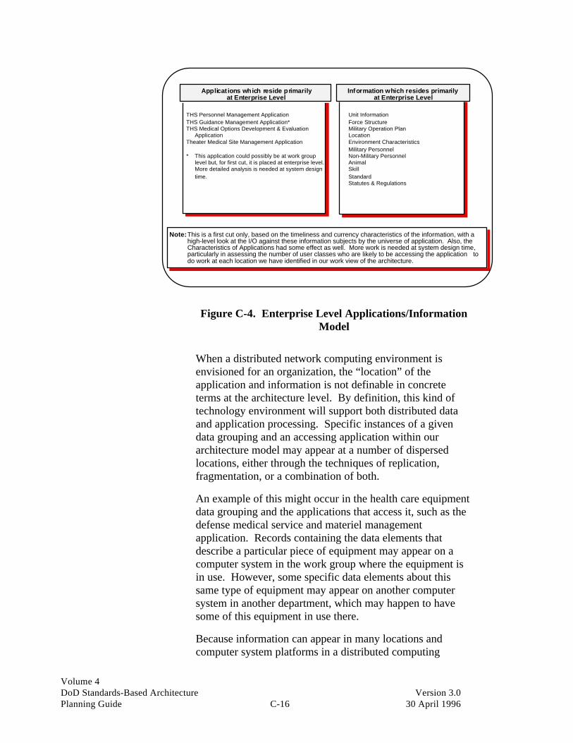
Volume 4DoD Standards-Based Architecture Version 3.0Planning Guide C-16 30 April 1996
Unit InformationForce StructureMilitary Operation PlanLocationEnvironment CharacteristicsMilitary PersonnelNon-Military PersonnelAnimalSkillStandardStatutes & Regulations
Information which resides primarilyat Enterprise Level
THS Personnel Management ApplicationTHS Guidance Management Application*THS Medical Options Development & Evaluation ApplicationTheater Medical Site Management Application
* This application could possibly be at work group level but, for first cut, it is placed at enterprise level. More detailed analysis is needed at system design time.
Note: This is a first cut only, based on the timeliness and currency characteristics of the information, with a high-level look at the I/O against these information subjects by the universe of application. Also, the Characteristics of Applications had some effect as well. More work is needed at system design time, particularly in assessing the number of user classes who are likely to be accessing the application to do work at each location we have identified in our work view of the architecture.
Applications which reside primarilyat Enterprise Level
Figure C-4. Enterprise Level Applications/InformationModel
When a distributed network computing environment isenvisioned for an organization, the “location” of theapplication and information is not definable in concreteterms at the architecture level. By definition, this kind oftechnology environment will support both distributed dataand application processing. Specific instances of a givendata grouping and an accessing application within ourarchitecture model may appear at a number of dispersedlocations, either through the techniques of replication,fragmentation, or a combination of both.
An example of this might occur in the health care equipmentdata grouping and the applications that access it, such as thedefense medical service and materiel managementapplication. Records containing the data elements thatdescribe a particular piece of equipment may appear on acomputer system in the work group where the equipment isin use. However, some specific data elements about thissame type of equipment may appear on another computersystem in another department, which may happen to havesome of this equipment in use there.
Because information can appear in many locations andcomputer system platforms in a distributed computing

Volume 4DoD Standards-Based Architecture Version 3.0Planning Guide C-17 30 April 1996
environment, our applications and information architectureimplementation must support methods of datasynchronization and control that are independent of theapplications accessing and updating the data groupings.
Other applications andsupporting technologyplatforms
The next area to consider is inter-enterprise connectivity.Connectivity with other systems in the three services, DoDunits, and other Federal agencies is increasingly important.The touted benefits of open systems technology (i.e.,portability, interoperability, and scalability) can mosteffectively be used in this arena. With the adoption ofopen systems (as described in TAFIM), in conjunction withthe mission-specific architecture developed in this SBA,the needed building blocks are available to “link” toentities “beyond the boundary,” as needed, in an effectiveway.
The need to evolve to aminimum set withcommon components
In transportable and/or mobile locations, a key issue is to“economize” the various communications so that they canbe routed through an efficient set of voice/data switchingand transmission systems. The goal should be to evolvethese systems to a minimum set that meets the currentlyenvisioned needs but which, like the networked computingenvironment with which they must interface, are built using“standard” components or building blocks.
This will not only move the organization ahead in terms ofinteroperability but also should reduce the number of uniquerepair parts and end units. This will provide cost andoperational efficiency benefits that complement theincreased productivity that seamless communications canbring.
Cross-service compatibilityis a key issue
The issues of compatibility and interoperability within thebody of existing and planned communications aresignificant. In the joint environment, there are still majorissues with mismatches on communications protocols, aswell as with system and applications software, which causesevere hardships when joint operations are attempted.
We are reminded that various armed services networksutilize commercial facilities for both switching andtransmission to augment private networks. AUTOVON is anexample of a service that rides on leased commercialfacilities. There are pros and cons to each approach.

Volume 4DoD Standards-Based Architecture Version 3.0Planning Guide C-18 30 April 1996
When commercial facilities are used, the organization gainssomething in that the operation of the network is not aburden, and the underlying technologies and services areconstantly being upgraded by the common carriers and VANvendors. However, the use of commercial facilitiesintroduces the need for minimum service levels and amonitoring process to ensure compliance. Also, thesecommercial networks have many more opportunities forsecurity breaches than do fully controlled private networks.Based on industry experience, however, when traffic doesnot require specific security considerations and when theyare readily available, commercial facilities are an advantagebecause of operational and feature-related factors citedabove.
The major drawback to dependency on commercial networkservices is that they may not be available in the diversegeographic and political environments within which the DoDmay have to operate. If they are available, their reliabilitymay not be guaranteed. These considerations may lead theDoD to rely almost exclusively on facilities and services thatare totally under its control.
The need to furtherinvestigate capacity andimproved mobility
For the DoD to realize the full potential of the networkedcomputing environment defined in this document, the areaof mobile communications needs further investment in twoareas:
• Additional capacity for gear that is currently effective
• Gear that will provide new capabilities to transmit andreceive a significantly increased amount of digital data inwireless mode.
This is an area that needs to be explored in more detail aseach application opportunity moves into the design stage.
From the USMC work done earlier in the year, the SBAteam has found that for mobile telecommunications twodistinct approaches are in use today:
• Deterministic routing (used by the Navy, USMC, and AirForce)
• Flood search routing (used by the Army).

Volume 4DoD Standards-Based Architecture Version 3.0Planning Guide C-19 30 April 1996
The flood search routing technique is used in the Army’sMobile Switch Routing Telecommunications (MSRT)system. The MSRT system most closely replicates thefeatures and capabilities of the commercial cellular phonenetwork. It allows “full service” while on the move. In thisregard, it is superior to the deterministic approach andshould be explored as an evolutionary path. Cellulartechnology is well tested in the commercial arena and isundergoing continual refinement. This should allow theDoD to take advantage of reduced costs and increasedreliability and bandwidth in the long run wherever thistechnology is feasible. It must be recognized, however, thatthis technology is not as easily established in a deployedenvironment as the deterministic method.
From the USMC project, it is understood that the Army isthe executive agent for all DoD tactical switching. Thisincludes defining, scoping, planning, scheduling, anddetermining the operational impact of changes to the tacticalswitching environment across the DoD services andagencies. Other components of the DoD would be wellserved by assigning resources to work closely with the Armyin this area exploring mobile and transportable switching andtransmission facilities options for interconnecting its ITcomputing platforms.
Security considerations Security should be implemented at a minimum accordingto DoD directives. TAFIM Volume 2 refers to a number ofstandards for security implementation. They are:
• Open systems security
• Multi-domain information security
• Multi-channel processing security
• Distributed processing security
• Security management.
Within the specific components of the technologyarchitecture, there will be opportunities to implement variousdegrees of security. Security can be implemented at theapplication level, the operating system level, the databasemanagement level, and at the external environment(platform/facility) level.
Multilevel security for secured clients and servers in thetechnology environment, as well as the possibility of
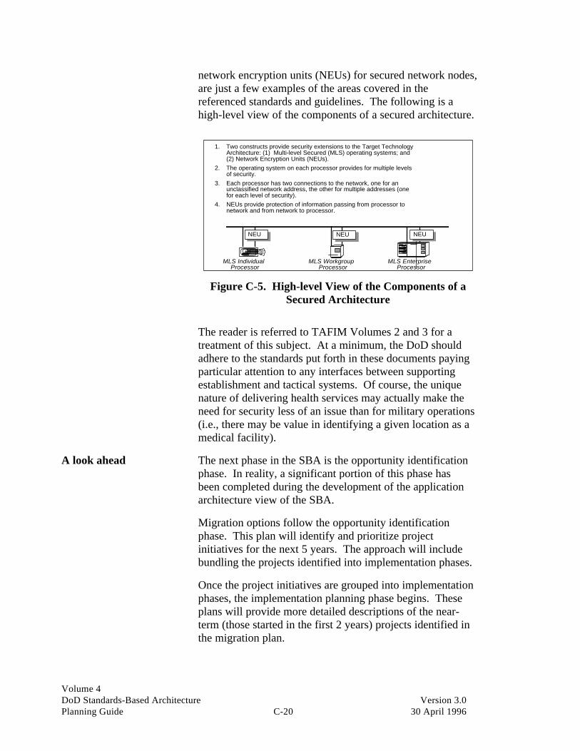
Volume 4DoD Standards-Based Architecture Version 3.0Planning Guide C-20 30 April 1996
network encryption units (NEUs) for secured network nodes,are just a few examples of the areas covered in thereferenced standards and guidelines. The following is ahigh-level view of the components of a secured architecture.
1. Two constructs provide security extensions to the Target TechnologyArchitecture: (1) Multi-level Secured (MLS) operating systems; and(2) Network Encryption Units (NEUs).
2. The operating system on each processor provides for multiple levelsof security.
3. Each processor has two connections to the network, one for anunclassified network address, the other for multiple addresses (onefor each level of security).
4. NEUs provide protection of information passing from processor tonetwork and from network to processor.
MLS IndividualProcessor
MLS WorkgroupProcessor
MLS EnterpriseProcessor
NEU NEU NEU
Figure C-5. High-level View of the Components of aSecured Architecture
The reader is referred to TAFIM Volumes 2 and 3 for atreatment of this subject. At a minimum, the DoD shouldadhere to the standards put forth in these documents payingparticular attention to any interfaces between supportingestablishment and tactical systems. Of course, the uniquenature of delivering health services may actually make theneed for security less of an issue than for military operations(i.e., there may be value in identifying a given location as amedical facility).
A look ahead The next phase in the SBA is the opportunity identificationphase. In reality, a significant portion of this phase hasbeen completed during the development of the applicationarchitecture view of the SBA.
Migration options follow the opportunity identificationphase. This plan will identify and prioritize projectinitiatives for the next 5 years. The approach will includebundling the projects identified into implementation phases.
Once the project initiatives are grouped into implementationphases, the implementation planning phase begins. Theseplans will provide more detailed descriptions of the near-term (those started in the first 2 years) projects identified inthe migration plan.

Volume 4DoD Standards-Based Architecture Version 3.0Planning Guide C-21 30 April 1996
When both the migration and implementation plans havebeen developed and reviewed by the ASC, implementationof the projects can begin. However, the SBA process is notcomplete until an SBA administration process is defined thatwill keep the SBA planning process alive and current withchanges within the DoD.

Volume 4DoD Standards-Based Architecture Version 3.0Planning Guide C-22 30 April 1996
This page intentionally left blank.

Volume 4DoD Standards-Based Architecture Version 3.0Planning Guide D-1 30 April 1996
Appendix D: GAE/GTE/GTP Definitions
Introduction This appendix contains the definitions of the GenericApplication Environments (GAEs) and GenericTechnology Environments (GTEs) introduced in Sections 3and 4. This is an initial set and is not intended to be “allinclusive.” Simply put, these should help to get a workteam started on its quest to define the necessary GAEs andGTEs for its functional area(s).
GAE sample definitions
Batch processing
Batch processing environments are characterized by theirability to queue work (jobs) and manage the sequencing ofprocessing based on job control commands and lists ofinput data. The results of this processing include updatedinformation files or databases and often printed reports orspecial forms that are themselves queued as output jobs.
As such, work is performed asynchronously from the usersrequesting the job or waiting for its printed output. In mostcases, the direct users of the environment are speciallytrained computer system operators.
These environments have been the mainstay of dataprocessing operations since their inception and willcontinue to perform critical recordkeeping and backgroundprocessing functions in conjunction with their relatedinteractive GAEs.
This is evidenced by the major transition that has occurredsince the punched card and paper listing days of the sixties.This transition has seen the migration from key punch,through remote job entry (RJE) and optical characterrecognition readers, to the use of on-line, interactive dataentry systems (a transaction processing environment) andinquiry processing systems that share a common database.
Use of file transfers between environments will continue asan effective means of interfacing with batch processingenvironments, only in a network server context rather thanthe conventional host computer relationship.
Batch application attributes include number, source, andnature of data capture transactions; timing and sequencing

Volume 4DoD Standards-Based Architecture Version 3.0Planning Guide D-2 30 April 1996
requirements; and volume and type of printingrequirements.
Transaction processing Transaction processing environments support on-linecapture and processing of information in an interactiveexchange with the user. These typically involvepredetermined sequences of data entry, validation, display,and update or inquiry against a file or database.
Environments using character keyboard entry/displaystypically base screen designs around the use of menus andelectronic forms. Those using GUIs are moving toward theuse of icons and images to support command activation andinformation display.
On-line transaction processing applications have grown outof document processing applications where timeliness andcurrency of processing a functional area transaction andcapturing its associated information is important.
Typical transaction processing application attributesinclude number, size, source, location, and complexity oftransactions; response time; and peak usage requirements.The nature, size, and complexity of associated subjectdatabases (or files) also need to be determined along withthe degree of sharing with other applications—as derivedfrom the information model.
Inquiry processing Inquiry processing environments support functional areaactivities requiring interactive selection, extraction, andformatting of stored information from files and databases.They are used in conjunction with batch and transactionprocessing environments to provide information retrievalusing either structured (routine) or ad hoc (definable)queries. They are intended to replace the need forextensive reporting systems by providing only neededinformation on demand.
These environments typically provide user-orientedlanguages and tools (often referred to as fourth generationlanguages) to simplify the definition of searching criteriaand aid in creating effective presentation of the retrievedinformation (including use of graphics).
Attributes include frequency of inquiries (prestructured orad hoc), types and complexity of searching, associated filesor databases, and types of presentation required.

Volume 4DoD Standards-Based Architecture Version 3.0Planning Guide D-3 30 April 1996
Decision support Decision support environments provide interactivemodeling and simulation tools that allow the user toanalyze the effects of alternative decisions. Thesemodeling and simulation tools typically work inconjunction with files and databases that were created frombatch or transaction processing environments.
As with inquiry processing environments, GUIs are used tosimplify the interactions for both building and using thedecision support models.
Attributes include the type and complexity of models andsimulation algorithms required, the frequency of use, theassociated files and databases, the complexity ofpresentation required, and response time.
Expert systems Expert systems environments use a type of artificialintelligence built with inference engines and knowledge orrule bases that take or recommend actions based onpresented situations and past “experience.” They are usedto augment human decision-making processes where the“expertise” or thought processes of the decision maker canbe defined as rules.
Expert systems are now finding their way into manyfunctional area applications, especially those involvingassessment or estimating processes, such as credit riskassessment. These environments are quite specializedtoday and are based on tight relationships between the“shells,” within which relationships are defined, and thecorresponding knowledge bases. As experience withapplying these environments grows, they will likelybecome more integratable with other environments.
Attributes involve size and speed of processing, the type ofknowledge base used, the type of inferencing processinginvolved, and whether it is used in batch or interactivemode.
Real-time control Real-time control environments support event-drivenprocesses supporting monitoring and actuation of physicalprocesses. For this reason, they are often referred to assensor-based systems. They are designed to handle andprocess interrupts from a variety of sources (typicallyinvolving some kind of sensor device or timer), processassociated information through some type of capture or

Volume 4DoD Standards-Based Architecture Version 3.0Planning Guide D-4 30 April 1996
control algorithm, and respond, if necessary, with anappropriate signal to a control or actuation device.
Unlike in the process, manufacturing, and raw materialsindustries, real-time control environments have a minorpresence in financial organizations. They have a role inbuilding security and facility management in suchapplications as access control systems, fire detection andalarms, energy management, and elevator controls. Thereare some applications, such as access controls, whereintegration with other security management environmentsmay be appropriate.
Text processing Text processing environments support the creation of textdocuments. They have evolved from the early wordprocessing systems of the seventies to be popularized aspart of the explosive application growth of desktoppersonal computers. They offer greatly improved editingand revision capabilities over the typewriters that they weredesigned to replace.
Because of their character and word orientation, theyoffered only limited abilities to improve the presentationand appearance of the final printed document. As a result,they are now losing ground to the graphics-oriented,document processing environments.
Text processing environment attributes include editing andformatting features, mail/merge capabilities, and documentfiling requirements.
Document processing Document processing environments extend the basiccapabilities of text processing to take advantage of thegraphics capabilities of today’s workstations and laserprinters. Consequently, they provide powerful documentand presentation tools for the end user.
These environments use an object-oriented approach tocomposing documents, allowing the incorporation ofgraphics, images, and even voice annotation, along withstylized text. They provide advanced formatting andediting features such as style guides, spell checking, use ofmultiple columns, table of contents generation, headers andfooters, and outlining tools.

Volume 4DoD Standards-Based Architecture Version 3.0Planning Guide D-5 30 April 1996
They require a GUI and often include support for scanningimages into bit-mapped representations. This SBA Guide,for example, was prepared using such an environment.
Attributes include types of objects supported, editing, styleand formatting features, resolution of display and printing,graphics generation capabilities, color or gray-scale usage,search and retrieval facilities, and document filingrequirements.
Electronic publishing Electronic publishing environments extend documentcreation and production tools to provide formal publishingcapabilities. This includes incorporation of photographicquality images and color graphics, very advancedformatting and style features, such as wrapping text aroundgraphic objects or pictures, and kerning (overlappingcharacters to optimize spacing).
These environments range from desktop versions tosophisticated corporate publishing systems and are oftenused through external publishing services. They generallyrequire specially trained “operators” who possess documentdesign and layout skills. They also interface with, orincorporate, sophisticated printing and productionequipment.
Attributes include resolution and color; editing, formattingand style features; type, size, and binding of printed output;and printing production rates.
Hypermedia processing Hypermedia processing is a new environment that extendsthe object-oriented approach to organizing and displayinginformation by utilizing various relationships between thestored or created objects. As such, it overcomes thelimitation of the printed page and allows the user to“navigate” through the compiled information based onmixed form objects in a manner that is consistent with theneeds and capabilities of the user, not some fixedpresentation format.
Through the use of the GUI and its extensions to includevoice/sound as well as video capabilities, hypermediapresents the ultimate in user communications. In effect, adynamic document is created by integrating the full rangeof information display capabilities interacting withassociated files and databases under user control.

Volume 4DoD Standards-Based Architecture Version 3.0Planning Guide D-6 30 April 1996
Attributes include the type and quality of mixed objectssupported, the types of relationships allowed, andnavigation tools.
Video processing Video processing environments support the creation ofvideo “productions,” either as sequential presentations or asinteractive presentations, under user control. They involveboth video and sound capture and editing, as well asincorporating still graphics and title generation capabilities.
They are becoming increasingly popular in corporateeducation as an adjunct or replacement for classroomtraining. They are also useful for marketing and productpromotion or in packaging general information and inquiryservices.
Attributes include nature (i.e., analog or digital) and qualityof capture and reproduction, editing facilities, ability tointegrate user commands, and sequential or direct fileaccess.
Document storage andretrieval
Document storage and retrieval environments are used toretain large volumes of stored information in documentformats. Originally these systems were based onmicroform media using film or fiche with special readers tomagnify the information. Computer output microfilm(COM) systems are used to store computer-generatedlistings or reports.
More recent introduction of optical storage technologies isallowing for storage of scanned or computer produceddocuments using digital storage techniques. These are nowavailable for use on PC networks as well as for largecorporate applications such as archiving. “Juke boxes” arenow available to load compact disks under computercontrol to achieve incredibly high storage and on-lineaccess volumes. Compact disks show considerable promiseas a means of distributing reference material with frequentupdates possible at low cost.
Attributes include type of media, speed and resolution ofscanners, compression techniques, ability to modify orupdate stored material, access frequency and response,media storage life, and retention volumes.

Volume 4DoD Standards-Based Architecture Version 3.0Planning Guide D-7 30 April 1996
Electronic mail Electronic mail environments support the storage andforwarding of directed messages, mail, and otherdocuments or files between sender and one or morerecipients. They provide the sender with facilities to createor define the message(s) or file(s) to be sent, use directoriesand distribution lists for routing information, assignpriorities, use preformatted electronic forms, and trace thestatus of messages sent.
The recipient is typically provided a mailbox with asummarized listing of incoming mail, a log of mailreceived and read, the ability to file or print mail ordocuments, and the ability to reply to or forward messages.
These environments are now capable of interfacingamongst themselves to extend their reach from work groupto public level (international) distribution. Some arecapable of “reading” text messages back via phone accessthrough the use of voice synthesis.
Attributes include sending and receiving features, numberof direct users, extent of directory and distribution listmanagement, interconnection capability, and securityfacilities.
Voice mail Voice mail environments offer the storage and forwardingof voice messages for a designated set of recipients. Theyare usually used as an extension of the phone system toprovide an alternate to message centers. They typicallyallow the recipient to retrieve recorded messages remotelyfrom any touch-tone telephone.
Attributes include quality of voice recording, user features,size of directories, and message management facilities.
Enhanced telephony Enhanced telephony environments provide improvedmeans of using the phone system for interactive audioexchanges between users. Features include callforwarding, call waiting, programmed directories,teleconferencing capability, automatic call distribution(useful for busy customer service areas), and call detailrecording.
These can be provided at the local (facility level) or acrosscorporate or public networks.

Volume 4DoD Standards-Based Architecture Version 3.0Planning Guide D-8 30 April 1996
Attributes include the features supported and the ease ofuse or help facilities provided through voice responseand/or intelligent handsets or integrated voice/dataworkstations.
Shared screenteleconferencing
Shared screen teleconferencing environments are anothernewly emerging type of system aimed at supporting moreeffective remote communications in an interactive modebetween two or more users. They combine an audioteleconferencing capability with shared commonworkstation “windows” that are refreshed on everyconferee’s workstation whenever someone displays newmaterial or changes an existing display.
In this way, conferees present and discuss displayablematerial interactively as in a meeting. They cangraphically annotate or modify the shared conferencewindow. The attractiveness of this environment is that itcan cost-effectively support many of the communicationrequirements of remote meetings using normal telephonelinkages with properly equipped workstations.
Attributes include display quality, refresh and transmissionrates, and conference control features.
Video teleconferencing Video teleconferencing extends the remote meetingenvironment to include full motion display of events andparticipants in a bidirectional manner. Thus, the facialexpressions and body language of presenters andquestioners is displayable to all participants in aconference.
There are a variety of schemes for directing the camerasranging from fixed position to sender directed to receiverdirected to automated sound pickup. This technology hasseen limited application because it required studio facilitiesand was very expensive in its introductory phases.Breakthroughs in charge-coupled cameras, displaytechnology, and high bandwidth communications shouldsee a resurgence in interest and application of videoteleconferencing.
Attributes include picture and sound quality, refresh andtransmission rates, and camera and conference controls.
Broadcast Broadcasting environments provide one-way audio oraudio/video communications between a sending location

Volume 4DoD Standards-Based Architecture Version 3.0Planning Guide D-9 30 April 1996
and multiple receiving locations. They include the use ofprivate TV facilities that can be purchased or leased forcorporate purposes. Many organizations are takingadvantage of these facilities and offsetting travel costs foruse in corporate announcements and product introductions.
Some information providers are now producing special-purpose TV shows for corporate subscribers as a substituteor adjunct for attending conferences (e.g., The ComputerChannel). These are often combined with audio returnlinks for question and answer sessions.
Attributes include the quality of production facilities andthe scope/range of the receiving network.
Computer conferencing Computer conferencing environments combine the meritsof document creation, E-mail, and conferencing byallowing groups and subgroups to participate in“conferences” via computer workstation. Theseconferences, however, do not occur in real time. Theconferees discuss proposed topics through interacting overtime. Conferees, or invited guests, can drop in or out ofconferences or subconferences at will. The ability to tracethe exchanges is provided.
These environments have become popular amongacademics and within university circles, beginning withbasic text capabilities. Combining the richness ofhypermedia with computer conferencing would create anenvironment in which the most capable and experiencedindividuals could be brought together remotely to focus ona critical topic using the most powerful electronic means ofcommunicating ideas.
Early forms of these environments are now available tousers of graphical workstations. Attributes include types ofdocuments exchanged, conference management andrecording facilities, and search and retrieval capabilities.
GTE sample definitions Each GAE is supported by one or more GTEs. Thecombination of the GAEs and GTEs provides theinfrastructure components for delivering systems andservices to the organization.
User interface services User interface services provide the basic means for users tointeract with the computing environment, managing the

Volume 4DoD Standards-Based Architecture Version 3.0Planning Guide D-10 30 April 1996
user interface for any class of user interface device from asimple character terminal to an advanced graphicworkstation. User interface services also provide supportfor the user in navigating through to the appropriate systemor server, authenticating the user and managing the user’sdesktop.
User interface services must support various input andoutput devices defined in the GAEs for each user class.There will need to be a variety of presentation servers usedby user interface services to support the various classes andtypes of interface devices. For example, there may be anX/Windows-based high-end GUI server and a lower levelcharacter-based server for different users.
User interface services interact with all other GTEsproviding them with the ability to receive and presentinformation to and from the user. Client applications andusers can be reasonably isolated from differences in theunderlying technology through the various presentationservers incorporated in user interface services. Forexample, the user interface should operate in a similar wayon a Mac, a PC, or a POSIX workstation.
Optional servers can provide encryption, data, and filemanagement for user interface services. These may or maynot be configured into the environment.
System managementservices
System management services support all activities dealingwith the management of the computing environment,interacting with all other GTEs to provide the managementcapability to monitor and control the total environment.
The objectives of system management services includeproviding adequate availability and performance across theenvironment, accurate and complete billing, changecontrol, and failure recovery. This environment providesthe basis for implementing specific applications and toolsto provide these capabilities.
GAEs and all other GTEs make use of system managementservices.
Communicationsmanagement services
Communications management services is another GTE thatis used by all of the other GTEs that want to communicate.This environment implements the communicationsinfrastructure consisting of various communication servers,name and directory services for resolving addresses, andauthentication and access control for ensuring the

Volume 4DoD Standards-Based Architecture Version 3.0Planning Guide D-11 30 April 1996
appropriate level of security. Thus, all the technologyassociated with communications and connectivity isbundled into this environment.
Specialized application servers for bandwidth managementand other communications functions would also beprovided.
Database managementservices
Database management services consist of the serversrequired for managing files and data within the technologyenvironment. It consists of data servers that implementdatabases and file servers that provide local and remoteaccess to various types of files.
Specific application servers may be implemented to isolatethe other environments from the physical structure andlocation of data. Implementation of a distributed datamanagement environment would require a set of specificapplication servers to support access, manage the physicaldatasets, and provide the appropriate level of integrity.
Hypermedia An emerging area for information management ishypermedia. Hypermedia provides a highly flexible way oflinking objects. Over time, documents, images, and otherobjects could be linked in hypermedia databases resultingin the elimination of document management services as aseparate entity.
Standards for information management will be required todeal with traditional data management as well as newertechnologies for storing other forms of information.Distributed data management capabilities are appearing invendor’s products and need to be addressed throughappropriate standards for their usage.
Transaction managementservices
Transaction management services implement theenvironment required for managing transaction processing.This environment includes the basic functionality andservers required to implement a transaction processingapplication. In today’s world, CICS would fit undertransaction management services. In the future, it isanticipated that a client/server environment will becomethe norm.
Transaction management services receives requests(transactions) from user interface services and actually

Volume 4DoD Standards-Based Architecture Version 3.0Planning Guide D-12 30 April 1996
performs the transaction processing. It may interact withinformation management, document management, ordistribution management services to update a database orpass the message on to another environment for processing.For example, a transaction generated by a user interfaceservices environment (i.e., a user using a workstation)could link with several environments before the transactionis completed.
The type and nature of the link will depend on theapplication requirements. For example, the link may be areal-time interactive link requiring completion by theserver before the client can do something else or may be amessage transfer link where the message or transaction ispassed to the other environment for later processing.
This environment consists of authentication and accesscontrol servers to control access to transaction processingand at least a data server with which to update or interact.
Document managementservices
Document management services are analogous toinformation management services, providing otherenvironments with the means to access and manipulatedocuments—either text only or some combination of data,text, voice, graphics, and image (a compound document).The key difference between these two technologyenvironments today is the level at which we can manipulatebasic elements of information. In information managementservices, we can access and manipulate each field withinthe file or database. In document management services, wegenerally access the entire file or document usingapplication specific formats for manipulating portions ofthe document. For example, the format for a MicrosoftWord document is different from WordPerfect; likewise,the way graphics is stored in each differs.
However, the distinction between the two is one that isbased on currently available technologies. Once we havecompound document architecture standards and databasesthat can handle document objects well, it’s likely that thetwo environments will merge and become one.
Conferencingmanagement services
Conferencing Management Services supports the real-timeexchange of information from one or more user clients. Itpermits a user to address a communication to any memberof a group without needing to know exactly who is in thegroup receive communications from all or selected

Volume 4DoD Standards-Based Architecture Version 3.0Planning Guide D-13 30 April 1996
members of the group without needing to know who iscurrently in the group, and to reply to them in a likemanner.
Conferencing services include various types of real-timeservices including voice conferencing (audio only), videoconferencing (audio and video) and computer conferencing(shared screen).
The Conferencing Management Services GTE utilizesName and Directory services to establish the parties for theconference and is closely linked with the CommunicationServices GTE to establish the physical linkage. It may alsoclosely link with hypermedia (in information managementservices) to provide a dynamic subject- and task-orientedasynchronous conferencing environment.
Distribution managementservices
Distribution management services support the distributionof messages, transactions, files, and any other informationbetween technology environments and physical locations.This environment consists of servers that implementelectronic mail, voice mail, and EDI. It also is tightlylinked to the communications management services GTE toprovide the actual communications between components.
Development services Development services provide support for all aspects ofsystems delivery including all phases of the developmentlife cycle, prototyping, and end user development. Thisenvironment interacts with the other GTEs to accessinformation on the current infrastructure and to implementchanges and enhancements.
Development services is built upon several servers toprovide authentication, location of objects (name anddirectory servers), and to implement specializedapplications. CASE tools and compilers are considered tobe application servers in this environment.
Repository services Repository services is an emerging GTE that will providethe repository environment for managing the technologyenvironment and the applications and data stored in theenvironment. The repository can store information aboutany “object” in the technology environment including, butnot limited to, the physical processors, applicationmodules, data, and processing functions. All of the GAEs,GTEs, components, and servers defined in this documentwould be entities in a repository.

Volume 4DoD Standards-Based Architecture Version 3.0Planning Guide D-14 30 April 1996
Repositories for systemconstruction
A passive repository, such as those being introduced byIBM, DEC, and others, can provide the dictionaries andsystem encyclopedias needed for defining and constructingapplication systems and data. This type of repository is theessential underpinning of a CASE environment, as itprovides the basis for storing information at each phase inthe development cycle and transferring that informationfrom one phase to another.
Repositories for systemsmanagement
Another type of repository, called the active repository, canbe used to store system information and to dynamicallymanage the IT environment. For example, with thecapabilities of an active repository, system managementservices could manage the execution of applications tooptimize performance and reliability.
Conceptually, repository services will interact with otherGTEs to provide a “single system image.” This is anenvironment where the computing and networkinfrastructure appears to the application and user as one“computer.” In this environment, repository serviceswould define the single-system image and manage whereand how processes are actually executed.
Server definitions Figure D-1 lists several server types. It illustrates a sampleset of logical components of an organization’s technologyinfrastructure. Entries may be added or modified.

Volume 4DoD Standards-Based Architecture Version 3.0Planning Guide D-15 30 April 1996
Name Translates network-wide logicalnames to network address
Directory Identifies logical names based onattributes
Authentication Establishes the needed identity of anetwork user
Access control Establishes access to desiredapplications or data
Cryptographic Provides encryption and keymanagement services
Communications Establishes linkages for a client(switching, router, gateway)
Time Ensures common network time
File Provides transparent access tonetwork files
Data Provides remote data services(database access)
Print Remote printing and printmanagement
Mail Provides electronic mail services
EDI Provides electronic data interchange
Applications Provides application-specific services
Presentation Manages the user interface for a clientuser (a person)
Sensormonitor/actuator
Manages interfaces to physicalsensors, actuators, and timers
Figure D-1. Server Classes
Name server The name server provides a means of finding an attributeof an entity given the unique name for any entity within thetechnology environment. Entities can be physicalcomponents (computers, workstations, network nodes),logical components (application modules, data storagelocations), or users.
The name server will be accessed frequently by clients tofind addresses for servers and other objects. Consequently,it needs to be implemented so it can provide high-performance response to queries. The search will be byunique name (unlike the directory server) so quick responsecan be provided.
Volume 4DoD Standards-Based Architecture Version 3.0Planning Guide D-16 30 April 1996
Name servers will also likely be highly distributed, soclients cannot assume the attribute provided by a nameserver is the latest version. While in 99 percent of thecases it will be correct, clients will have to implement arecovery mechanism to deal with the exceptions.
There are few vendor implementations of name servers inthe market today. Likewise, the standards bodies are stilldrafting industry standards for name servers andapplication programming interfaces to name servers. DEChas an early implementation and architecture for adistributed name service and is worth investigating.
Directory server The directory server provides a means of finding a set ofentity attributes based on qualifiers, such as a telephonenumber or other descriptive characteristic. Unlike a nameserver, the searches are often ambiguous and based on acombination of attributes.
Clients may use a directory server in the future for queriessuch as, “find me a vector processor with 40 MIPsperformance” or “find me a storage device with 40 MBfree space.”
Directory servers will not be accessed as frequently asname servers. Performance will not be as critical as thename server’s because of the lower rate of access and thefact that the access by directory server clients is done on anad hoc-query basis, often under the direction of a user (e.g.,find John’s telephone number).
Like the name server, clients cannot assume that theattribute provided by the directory server is the latestversion. While in 99 percent of the cases it will be, clientswill have to implement a recovery mechanism to deal withthe exceptions.
The directory server may become a client to a name serverto resolve physical and logical addresses.
Authentication server Validation of users, nodes, programs, and other requiredobjects is performed through the authentication server.Secure channels using encryption and/or some form oftrusted communications provide the linkage between clientand server.

Volume 4DoD Standards-Based Architecture Version 3.0Planning Guide D-17 30 April 1996
Access control server The access control server maintains the access control listsfor each object within the technical environment. Theaccess control server determines whether access to therequested system object is authorized.
Cryptographic server Encryption services for any process are provided by thecryptographic server. The cryptographic server alsomanages keys and handles distribution of valid keys amongthe cryptographic servers. A centralized key managementserver may be required.
Communications server The communications server forms the basis of managingconnections between objects in the environment. Itprovides connections between objects independent of thephysical implementation of the network and ensuresaccurate delivery of messages between objects.
The communications server, from the point of view of theGTEs using it, provides OSI Level 7 services to theenvironment. Gateways, routers, bridges, and protocolconverters are included in the communications server butare invisible to the clients of the communications server.Bandwidth and capacity management support are alsoincorporated in the communications server to provide thebasis for optimizing the capacity and reliability of thenetwork.
Utilization of this server will provide applications withtransparent access to communications services in theenvironment. The communication server has the ability tosupport a transparent computing environment whereapplications and users do not have to be concerned with thelogical and physical implementation of the technology.
Time server A critical need in distributed environments is to make surethat time is synchronized throughout the environment.This is especially important in distributed transactionprocessing applications and database environments wherelogs need to be kept synchronized to support transactionbackout and recovery.
The time server provides time synchronization services toall objects within the environment. Individual objects will

Volume 4DoD Standards-Based Architecture Version 3.0Planning Guide D-18 30 April 1996
call on the time server to get an accurate, consistent timefor their use.
There has been limited vendor and standards activity in thisarea. DEC has proposed their time server to OSF as part ofthe distributed computing environment request fortechnology.
File server The file server provides transparent access to files fromworkstations and other clients. Unlike a data server, thefile server provides access and linkages to the filedirectories and is not aware of the contents of the file.Processing of contents of a file needs to be performed bythe client. The file server does no client-visiblemanipulation of the data within a file. Essentially, the fileserver provides the client with the use of a virtual diskdrive and little else. For example, in a workstationenvironment, the workstation would perform all theprocessing on the file.
This can create synchronization and reliability problemswhen the file server is used as the place for storingdatabases and other files that are accessed by several users.The file server is best used when accessing an entire filesuch as a word processing document or a spreadsheet.
Over time, the file server may be replaced by a data serverbecause of its improved controls and better managementcapabilities.
Data server The data server provides data services to clients. A clientwill send a request to a data server (sometimes called adatabase server) and the server will respond with theresults of the request. The accessing and updating of thedata maintained on the data server is performed by the dataserver, not by the clients.
The data server can provide additional services. Forexample, recovery and rollback capabilities can beprovided. It supports the implementation of better controlsby managing access to the data resident within the server.
The data server can also be optimized to the type of data itis being asked to manage. For example, a data server couldsupport archiving and be based on optical storagetechnology rather than magnetic. In the future, data servers

Volume 4DoD Standards-Based Architecture Version 3.0Planning Guide D-19 30 April 1996
will likely provide access to multiform data that includesvoice, text, and image objects as well as data.
Print server The print server provides common printing services toclients within the environment. The print server providestransparency between the client and the physical printer.For example, differences between different vendors’ laserprinters should be transparent to the client.
In addition to device-independent printing, the print serveralso provides queuing, priority management, and otherprint management services so that the physical printers canbe effectively managed.
Printers can be any local or remote output device capableof printed output, including traditional character and lineprinters, laser printers, fax machines (the printing portion),and even microfilm printers.
Mail server The mail server provides mail transfer capabilities for acommunity of users. The basic function is to support thestore and forward of interpersonal messages between users.The mail server moves messages based on the contents ofthe message envelope not the message’s contents.
The mail server also manages the users’ mailboxes. It canautomatically acknowledge delivery to a user’s mailbox.
The server will support multiform mail transfer (voice-mail, graphics). In the near future, compound maildocuments could be transferred using this server.
EDI translation server The EDI translation server interprets the content of EDImessages and routes them to the appropriate EDI partners.The EDI server works hand in hand with the mail serverbut needs to interpret the EDI message to translate it orroute it to the correct recipient.
The EDI server also provides queue management facilitiesand assured delivery of messages.
Application server An application server provides a set of standard applicationservices to clients. It is a form of packaging an applicationas a commonly used and reusable component of theinfrastructure.

Volume 4DoD Standards-Based Architecture Version 3.0Planning Guide D-20 30 April 1996
The application server must:
• Have a defined application programming interface andmessage structure
• Be independent of the client
• Provide a set of generic services that can be utilized bya variety of clients (versus a set of services directlylinked to a specific application system)
• Hide its underlying process and data from theapplication—be essentially a black box.
Breaking specific application systems into a client/servermodel of design is desirable, but the result is notnecessarily an application server. The key is to haveindependence from the client so the server can be utilizedby a variety of clients throughout the organization.
Presentation server The presentation server provides presentation services for aclient application and/or a person. It creates a genericpresentation environment that is independent of theunderlying technology and provides a means for users tointeract with the technology environment.
The presentation server is the most user-visible portion ofthe technology environment. It is the place where the“look and feel” of the organization’s infrastructure will beimplemented.
Various models and standards for the user interface areavailable. It should be noted that standards and availableproducts for the user interface are at a very early point intheir evolution.
The presentation server will need to accommodatecharacter-based terminals for the foreseeable future, but weexpect a migration to graphic-based terminals to occur overtime.
Sensor monitor/ actuatorserver
The sensor monitor/actuator server provides clientapplications and users with an interface to physical devicessuch as cash dispensers, building monitoring systems, orany other device that interacts with physical controlsystems.

Volume 4DoD Standards-Based Architecture Version 3.0Planning Guide D-21 30 April 1996
This server is used extensively in manufacturingapplications. It can provide the interface to manufacturingequipment, robots, and the like.
Generic technologyplatforms
There are six technology constructs, or GTPs, are used toprovide the fundamental building blocks in a standards-based architecture. Each GTP can function as a fullyindependent “architecture” in that they each have aninterface along with processing, storage, andcommunications capabilities. As such, each GTP mayoffer alternative choices in delivery of the same GAE. Forexample, all six constructs are capable of supporting someform of electronic mail, with different associated strengthsand weaknesses.
Six Constructs -Contributing and Competing Technology Architectures
Intelligent Wide AreaNetwork Systems
Establishment-basedSwitching Systems
Local AreaNetwork Systems
Enterprise orCorporate Processing
Systems
Divisional orDepartmental Processing
SystemsDesktop or Portable
Intelligent Workstations
• Value-added WAN switching services• Transparent access to servers• WAN management
• Premise-based switching services• Gateways to WANs• Associated servers (e.g. IVR, V-Mail)
• Local transport and resource sharing• File servers and device servers
• On-line and batch processing services• Serving large base of networked users
• Online transaction processing services• Serving primarily local users
• Personal computing services and access to network(s)• Serving single user
Figure D-2. Six Generic Technology Platforms
It is also important to note that the GTPs do not connote aparticular size/capacity. The names for the GTPs connotethe usage of the processor, not size. In fact, departmentalprocessors may be larger or smaller than enterpriseprocessors. Some processors acting as LAN servers could

Volume 4DoD Standards-Based Architecture Version 3.0Planning Guide D-22 30 April 1996
well be larger than departmental or enterprise processorsdepending on the way a given company wishes to organizeits work.
Used in combination, these GTPs can be used to describeany architecture environment that current informationtechnology can deliver. Most large organizations arealready using multiple combinations of these GTPs.Having determined the appropriate combination of GTPs tosupport the organization’s application requirements, thekey to integration is in defining standards that will ensurethe highest level of compatibility and portability across theGTPs at both the application and technology platformlevels.
Figure D-3 shows a first level of decomposition of eachGTP, illustrating the principle components for whichstandards need to be defined.
USERI/F
MANAGEMENTUSER
APPLICATIONSDATABASE
MANAGEMENT
LANGUAGES AND TOOLS
COMMUNICATIONS MANAGEMENT
OPERATING SYSTEM
Figure D-3. Components of Generic TechnologyPlatforms

Volume 4DoD Standards-Based Architecture Version 3.0Planning Guide D-23 30 April 1996
At the component level, we see that all six of the GTPsshare a similar structure. Thus, the key to effectiveintegration and sharing in the technology environment is toadopt standards for each component of GTPs, whichminimizes the number of different interfaces amongcomponents. In today’s technology marketplace, vendorsare increasingly agreeing on standards at the interface,from GTP to GTP, and within the components of the GTPsthemselves. Organizations should adopt technologystandards which take advantage of this trend.

Volume 4DoD Standards-Based Architecture Version 3.0Planning Guide D-24 30 April 1996
This page intentionally left blank.

Volume 4DoD Standards-Based Architecture Version 3.0Planning Guide E-1 30 April 1996
Appendix E: Migration and Coexistence
The framework formigration
The selection of migration in support of change is always adifficult task and fraught with difficulties and risks.Because the task of migrating information systems andtechnology is risky, the constraints of migration have to betaken into account in selecting direction and strategy.Many worthwhile projects have floundered becausemigration was not adequately scoped prior to adoption. Inthe future, the adoption of open systems and standards-based architectures will reduce the complexity of manymigrations to the point where migration will become justone of the scheduled phases, without exposure and withoutimpact on the viability of the strategy. In the meantime,great care is needed to embark on the journey with safety.
As the information infrastructure extends throughout anorganization, users draw more and more on the services ofa variety of systems. An essential part of migrationplanning is to accommodate change in one area whileaccommodating continuity of service in other areas.Coexistence requirements are often as difficult to meet asmigration requirements.
What are the migrationobjectives?
Any migration planning exercise needs to have a clearlydefined statement of objective and specification ofrequirements. In the planning process described, theobjectives and primary requirements will emerge fromPhase 1, architecture framework, with some refinement ofthese emerging from Phase 3, target architecture.
For some organizations, the selection of objectives and themovement towards openness will proceed in closecooperation with the development of new functional areasystems. For organizations that have a significantinvestment in infrastructure, or have a multivendorenvironment, the migration objectives may be very muchmore technology oriented. Some of the typical migrationobjectives in the latter category are:

Volume 4DoD Standards-Based Architecture Version 3.0Planning Guide E-2 30 April 1996
• To move away from dependence on a proprietaryinfrastructure that has an uncertain future
• To introduce increased interoperability betweenplatforms in the current environment
• To introduce increased openness and integration acrossplatforms in the current environment
• To introduce increased standardization in the currentenvironment so that economies are realized
• To standardize a multivendor environment
• To introduce standards of compliance providing a levelplaying field for equipment acquisition
• To achieve portability and scalability
• To increase the extent of reuse of technology,applications, and people
• To create an environment that better accommodatesnew non-proprietary technology
• To introduce new technology
• To facilitate interconnection and interpretability withother organizations
• To work towards the network computing vision withinthe organization or with other organizations.
Development of these objectives so that they provide clearimprovement rather than just a rationalization of costs willflow by examination of key technology issues as theyaffect the functional area within DoD. Typical questionsmay define requirements for openness and standardization:
• What interconnection with suppliers is required toimprove service/support or reduce costs?
• What interconnection with internal customers isrequired to improve the service, provide superiorproducts, or reduce costs?
• To what degree can information technology improve orcreate services?

Volume 4DoD Standards-Based Architecture Version 3.0Planning Guide E-3 30 April 1996
• Are there particular forms of technology that willchange the nature of information processing within theDoD?
• What forms of electronic product distribution (withinthe DoD) would benefit our functional area?
• What industry-based technology initiatives do we needto come to terms with or accommodate?
• What are the interpersonal communication flows onwhich our organization depend? What will the benefitof interorganizational electronic mail be?
• What functional area/transaction documents flow withother organizations (outside the DoD)? What benefitswould accrue by passing these electronically?
Dilemmas The evolution of standards is proceeding on many frontsbut not at the same pace. The dynamics of standardsevolution relate to the complexity of the subject area andthe extent of vested interest supporting standardizationversus the extent of vested interest resistingstandardization. The scene is complicated by the variety ofstandards bodies and the spectrum of standardizationcovering de facto standards through to de jure activity.
Of the technology components identified as major buildingblocks, the most significant level of standards activity isproceeding in the areas of database interface, operatingsystem interface, graphical user interface components, andcommunications network protocols. In addition, languageshave traditionally been an area of standards activity.
The drive for change comes with the attendant problems.While they have been dealt with in some detail in thearchitecture sections, they remain to be addressed bymigration strategies. The dilemmas are repeated here anddescribed in slightly more detail because they have a directimpact on migration.
GUI vs. character vs.block mode terminals
The significant attention given to GUIs flows directly fromthe level of functionality and ease of use that they canprovide. To fully utilize this technology, applications mustbe modified to support the selected GUI interface.
The conversion of existing character mode or block modeprograms to support GUIs requires significant change in
Volume 4DoD Standards-Based Architecture Version 3.0Planning Guide E-4 30 April 1996
program structure and presentation programming. Thesupport of the enhanced functionality requires work toestablish and support pull-down menus, pointing devices,and context sensitive tools. The introduction of a GUIapproach will, in most instances, require distribution ofsome part of the application functionality or presentation.Support of distributed function requires an infrastructurethat provides services such as program distribution,software inventories, remote diagnosis, and file transfer.These increase the size of the migration activity.
Another area of difficulty is that the selection of a GUIcomes with its own set of infrastructure assumptions. Anystandards-based initiative reflects its heritage. Forexample, X/Windows emerged from the character-basedsegment of the industry. Selection of an X/Windows-basedimplementation creates a demand for network facilities thataccommodate character mode terminals. For reasonableresponse times, X/Windows needs a local host; thus, theinfrastructure requirements may even be in conflict withthe needs of character terminals that are currentlyconnected to a remote host.
Selection of a GUI creates a need to examine impacts andmigration strategies for both applications and networks.
Peer-to-peer vs.master-slave
A common thrust and assumption in many standards-basedactivities is that information technology will be deployed ina peer-to-peer manner thus accommodating distribution inany of its many forms. Again, this assumption requiresquite a different infrastructure than that used to support theconventional character mode or block mode terminals, bothof which reflect a master-slave orientation.
Peer-to-peer connections require a communicationsnetwork that embodies capabilities such as those inherentin LANs and wide area packet networks. By and large, theWANs established to support block mode terminals arepacket based and are thus well suited to support peer-to-peer interoperability. Character mode WANs areunsuitable for support of peer-to-peer communications norare packet networks able to adequately support charactermode applications across the network. Therefore, in thiscase, the movement to standardization is more easilyaccommodated within a block mode world than it is withina character mode world.

Volume 4DoD Standards-Based Architecture Version 3.0Planning Guide E-5 30 April 1996
Database Another area of significant standards activity is that ofdatabases. The adoption of SQL and the relational modelestablishes the cornerstone of standards in this area. Whilestandards have established significant standardization interms of the data interface language, other areas ofsignificance for programming, such as interoperability anddistribution, have not received the same attention and donot have communality across the marketplace.
This area of standardization also illustrates the conflictsbetween standardization and innovation. The emergence ofobject-oriented databases disturbs the status quo and callsinto question the breadth of applicability of the incumbentstandards.
Again, converting programs to make use of the relationalmodel is no simple matter. While it is possible to developmigration tools that allow programs with old forms of datanavigation to access SQL databases, this does not exploitthe capabilities of SQL. To gain the full benefit of theSQL model requires that information be remodeled andthat applications be redesigned.
Finding an answer It is impractical to simply toss a coin when selecting astandard. It is essential that any drive towardsstandardization be initiated in the context of a well-thought-through architecture for the organization. Thetrends toward distributed processing and GUIs areimmutable. The deployment of these styles of computingneeds to be approached carefully by operating within theconstraints of available technology and being consistentwith the structure of technology placement that matches thelong-term direction and shape of the organization.
In resolving these dilemmas, the migration plan will haveto adopt a strategy that reflects an assessment of:
• What do we wish to protect and what are we preparedto discard?
• To what degree do we wish to standardize?
• Do we want standards to be vendor neutral, or are wesatisfied with proprietary standards?
Taking control andresponsibility
Answering questions such as these is, for someorganizations, an entirely new activity. For manyorganizations, the issues of longer term technologyarchitecture and direction are simply left in the hands of the

Volume 4DoD Standards-Based Architecture Version 3.0Planning Guide E-6 30 April 1996
selected supplier. At this stage in the development ofstandards-based systems, a standards-based policy requiresthe organization to accept responsibility for its owndirection. The organization must clearly understand that itis choosing to pursue its own path through the morass oftechnology choices rather than simply following the lead ofa particular vendor.
Making this decision entails some risk and requires that theorganization retains staff with the time and ability to guidethe organization. Against these costs will be balanced thebenefits that flow from openness. Pursuing this pathrequires determination and commitment from the entireorganization.
Determinants ofmigration size andcomplexity
As the scenarios show, the extent of migration activityvaries significantly according to the:
• Current architecture
• Target architecture
• Organization size
• Value of technology to the functional area
• Organization complexity
• Extent of change
• Impact on culture
• Cost.
For some organizations, the migration activity may beminor and may not need to be supported by extensivestructure and analysis. For these organizations, the extentof planning implied in this appendix may be totallyinappropriate. It may be that they can simply “just do it.”
For others, the issues of migration and maturity of thestandards-based products will be such that, after analysis,the migration costs and issues will loom sufficiently largethat the organization will determine that its best interestsare served by the retention of a proprietary strategy (at leastfor the interim—until the costs become less prohibitive).

Volume 4DoD Standards-Based Architecture Version 3.0Planning Guide E-7 30 April 1996
Baseline characterization The inventory activities of this phase will provide keyinformation for migration planning on the valuation ofexisting assets and the identification of risk. From amigration point of view, the necessary inputs may include:
• Valuation of existing investments in hardware,software, applications, development staff, operationsstaff, users, management, and management process.
• Critical evaluation of existing suppliers, their prospectsfor survival, and continuity of their product lines. Isthe vendor a special-purpose vendor and thus likely tosurvive in its niche, regardless of standards support?
• An estimate of risk, cost, and opportunity cost relatingto the current inventory. For vendors or product linesthat may not survive, what is the cost to theorganization of loss of impetus as a vendor winds downinvestment and turns attention to alternative productlines? What is the cost arising from reduced marketsupport? What is the opportunity cost from use ofobsolete equipment?
Target architecture —examine alternatives
The selection of a target architecture requires someunderstanding of migration impacts in order to movetowards a practical target. Selection of a target will need totake into account the issues that emerge from the baselinephase while addressing the objectives and targets. Some ofthe questions that may help the issues emerge are:
• Do we have requirements that can only be addressedwith a proprietary-based architecture?
• What is the impact of past investment? What base mustbe protected?
• What are the general levels of costs associated withdifferent architectures? What is the impact on the totallevel of expenditure across the organization acrosstime?
Alternative architecture targets may emerge by looking atthe organization from various views. Looking at theorganization in terms of its functional areas will highlightstandardization within a related application set and maysubsequently identify pilot opportunities that are notclosely coupled with other application systems. Viewing

Volume 4DoD Standards-Based Architecture Version 3.0Planning Guide E-8 30 April 1996
the organization in terms of work organization and the needfor application access of each grouping of staff anddepartment will provide input to the needs of theorganization in terms of GUIs and integration on the desk.
An inventory-oriented view focusing on the proliferation ofplatforms will focus on the need for rationalization ofplatforms and uniformity in infrastructure. Such a viewneeds to include the network platforms.
A management view of the organization will focus on theintegration of information and the needs of theorganization.
Opportunityidentification
For some organizations, the opportunities for migrationwill be in the form of specific functional area initiativeswith supporting applications. The difference will be thatimplementation will be based on the adoption of astandards-based architecture. From the functional areapoint of view, these projects may not represent a significantchange from the normal approach of justifying andproceeding with information system implementation.Where such opportunities are limited in scope andproliferation, they make ideal pilot candidates.
For some organizations, open systems adoption will requirea gradual modification and migration of the infrastructure.In these situations, there is a significant need for thecommitment of the organization to sustain migration over along period.
Migration options The evaluation of migration requires that the alternativemigration strategies be examined to determine the effort,cost, and adequacy of the approach. This requires researchand validation of the elements of each possible migrationsolution. Typical questions that need to be asked are:
• Is it viable?
• What products does it need? On what standards arethey built?
• When will the products be available?
• What can we do to position for future decisions?
• What education and learning must be undertaken?

Volume 4DoD Standards-Based Architecture Version 3.0Planning Guide E-9 30 April 1996
• How do we introduce the consequent cultural change?What is the cultural change for development staff,operational staff, users, and management?
• What are the relative costs of each option?
• What benefits are delivered by the option?
A caution to the reader The migration scenarios selected are hypothetical andhave been developed for the purpose of illustration only.They do not attempt to portray real life situations. Caremust be taken in using the scenarios in that, while the DoDmust individually assess its own requirements, thescenarios presume requirements. While the DoD willevaluate migration options based on the latest marketknowledge, the scenarios presume the market at a point intime.
The comments and conclusions made about the scenariosare general only, they are not complete. They should notbe cast in the light of recommendations. It should also berealized that the solutions presented in each scenario arenot necessarily the only ways of solving the hypotheticalproblems. The investment decision process and relativesensitivity to costs are different for every organization.These scenarios do not provide guidance or commentary onthe relative costs of alternative migration options.
Scenario 1:proprietary vendor witha commitment to POSIX
This is a general scenario that covers a medium-sizedvendor offering POSIX interfaces to a proprietaryoperating system as part of a general commitment tovendor-neutral standards. It is assumed that the vendoralso commits to XPG and OSI.
In this case, the vendor is committing to comply with theopen APIs so that applications written to the standards areportable onto or from their platform. Vendors providingthis level of standards support aim to accommodateportability of applications across platforms but have a viewthat the platform, as supplied by the vendor, is complete.
The alternative view, that standards should be used to allowinterchangeable components within generic platforms, hasnot been considered in any scenario. This concept ofopenness is not supported by hardware vendors but doesreceive some support from software vendors and third-party peripheral suppliers.

Volume 4DoD Standards-Based Architecture Version 3.0Planning Guide E-10 30 April 1996
While every vendor offering POSIX-compliant platformshas a proprietary offering below the interface, the class ofvendors represented by this scenario differs from theprovision of a POSIX-compliant UNIX in that:
• The capabilities of the proprietary offering aremaintained intact within the platform; thus, a singleplatform can operate in either of the two modes.
• The platform benefits in that the proprietaryenvironment is probably more mature than the UNIXenvironment. This presumption may not always becorrect and will change as the UNIX-based offeringsdevelop.
• The platform will be developed by the vendor inresponse to two client sets (proprietary and open). It ispossible that the proprietary mode will always receivefunctional enhancement first.
• The development of a new function is limited by theresources of the vendor. The vendor will not normallybe able to roll in a function developed by the industryfor the UNIX vendors or by the two groupings ofUNIX-based platforms (OSF and UI).
• The vendor’s solution will not be able to benefit fromthe ideas of component interchange should themarketplace force vendors along this path.
Current architecture The current architecture is shown in Figure E-1. Theprimary characteristics of it are:
• A proprietary CPU running proprietary operatingsystems with proprietary file systems but with POSIXcompliance.
• A platform that is able to include an SQL DBMS.
• Language support that includes COBOL, proprietarylanguages, report writers, and query languages.
• The platform includes a number of mission-criticalapplications that operate using on-line update to thedatabases.
• Normal terminal support that uses block modeterminals, and all applications written to support blockmode terminals.

Volume 4DoD Standards-Based Architecture Version 3.0Planning Guide E-11 30 April 1996
DBMSOperatingSystem
ApplicationsComms
Prop. POSIX
X.25PacketNetwork
Figure E-1. Current Architecture
• The vendor has committed to support OSI, has anX.400 product in place, and an FTAM product due tobe released—it is expected that the vendor will fullysupport the level 7 OSI protocols a little behind marketadoption.
• The vendor has support for X.25, and terminals mayaccess applications via X.25 operating in block mode.
Migration objectives There is a significant investment in application software;thus, there is a desire to protect this investment. There isno desire to change the user interface for existingapplications.
There is a significant investment in block mode terminals.It is required that these be retained for their life rather thanbe discarded.
There is a desire to use a GUI for some new applications,which creates a requirement for both the GUI and blockmode operation to be accommodated.
There is a desire that both old and new applications be ableto operate on one platform and share the networks andinfrastructure.

Volume 4DoD Standards-Based Architecture Version 3.0Planning Guide E-12 30 April 1996
There is a requirement that data belonging to old or newplatforms be available across both types of applications.
There is a requirement that the software for existingoperations, network management, capacity management,storage management, etc. continue in use.
Target architecture The target architecture requires that:
• The POSIX interfaces be enabled
• The DBMS be SQL based
• The programming language be a standard language
• A GUI be introduced.
Migration options The scenario assumptions have resolved much of thediscussion regarding alternative strategies. The scenarioassumes coexistence is available.
Option 1 Leave all old applications intact and write all newapplications using the POSIX-defined interfaces. Ignorethe need for a GUI and continue to use block modeterminals with the existing networks.
On analysis, this is practical for only a small percentage ofapplications. Few applications can live within the boundsof the implemented POSIX standards. A number of batch,OLTP, and process control applications cannot operatewithin the bounds of the available POSIX specificationsand/or support. New applications requiring thisfunctionality must use the proprietary facilities.
There are also some conflicts between the POSIX-definedinterfaces and block mode operation.
Option 2 Same as Option 1 but also make use of a non-open GUI.
This requires some distribution of the presentation layer.The selected GUI is Microsoft Windows. By using PCs ona LAN with block mode emulation to the host, it is possibleto accommodate both the block mode terminal applicationsand the GUI-based applications, but the GUI is not open.
Option 3 Same as Option 1 but using X/Windows as the GUI fromthe central host.
This option proved unviable. X terminals were not able tosupport block mode emulation. Workstations able tosupport the block mode operation and X terminal
Volume 4DoD Standards-Based Architecture Version 3.0Planning Guide E-13 30 April 1996
emulation could not viably attach through the network tothe host-based X applications.
Option 4 Same as Option 1 but using X/Windows and distributedpresentation.
Apart from the issues raised in Option 1, the X/Windows-based GUIs are somewhat incompatible with the LANfacilities required to support the block mode terminals.The solution requires that each terminal be replaced by aworkstation, with a presentation layer being distributed tothe individual workstation. The presentation layer thenrequests service from the applications in the central host.
By using the existing block mode as the interface, it ispossible to use X/Windows over existing applications.
Option 5 Move to OSI network while retaining block modeterminals and supporting X/Windows.
Again, this scenario is only viable where functions can bedistributed to the workstation. The use of X/Windowsprecludes the use of OSI all the way to the terminals. Theuse of X/Windows also displaces the currently maturenetwork facilities and network management capability.
Preparing for migration The scenario revealed a number of exposures. Thefollowing activities are warranted:
• An assessment of the viability of the supplier. Shouldthe supplier be unable to continue to maintaindevelopment of the two product lines, this scenario willrevert to be similar to Scenarios 1and 2.
• An assessment of the vendor’s development funding isnecessary to determine what confidence there is thatnew open functionality will be delivered to match themarketplace. It is assumed that the vendor will beprepared to reveal internal information to indicate theviability of the strategy.
• A brief on standards activity is needed to fullyunderstand the complexity of standards compliance inan environment that must also continue to support theproprietary standards.

Volume 4DoD Standards-Based Architecture Version 3.0Planning Guide E-14 30 April 1996
Preferred migration The preferred migration option is Option 2 based on theexisting network and a non-open GUI.
The improved compatibility with the installed base over theX/Windows options is significant. Given the inability tofully comply with open standards, it is not clear what thebenefits are of partial compliance.
The selected approach includes:
• Use of POSIX standards only where the wholeapplication is able to operate within the standard
• The ability to distribute a presentation layer but noobligation to do so for all applications
• The ability to make use of the GUI for new applicationsbut no obligation to do so
• The introduction of standards-based LAN platformsand workstation platforms to replace the existingterminals and cabling system
• The ability to purchase application packages that workto the POSIX interface standards.
This option provides the confidence of staying with the oldwhile being able to watch the emerging marketplaceactivity in the open arena.
Conclusions • A migration is not possible without a total commitmentto open standards.
• The use of X/Windows does not fit well with the blockmode orientation of the vendor.
• The use of OSI requires some distribution of function.
• The movement away from proprietary networks andblock mode operation raises some issues of transactionintegrity and recovery. Even though a LAN cansupport these requirements, the devices attached to theLAN may not unless they emulate the block modeoperation.
For example, a remote check printing application thatrequires confirmation from the printing device that printouthas completed without a paper jam as a condition oftransaction commitment will not be able to obtain the

Volume 4DoD Standards-Based Architecture Version 3.0Planning Guide E-15 30 April 1996
required status advice under several of the migrationoptions.
• The use of a GUI requires some distribution offunction.
• The accommodation of distributed and centralizedapplications is difficult. The mix of proprietary forcentralized and open for distributed is difficult.
• The adequacy of the strategy assumes that the vendorwill survive.
Scenario 2:complex multivendorinstallation
This scenario covers a large conglomerate organizationhaving a variety of vendors represented in different parts ofthe organization. It is assumed that there is a mix ofvendors including IBM, Digital, Unisys, UNIX platforms,and PCs.
Current architecture The current architecture is shown in Figure E-2. The primarycharacteristics of it are:
• There are no corporate systems. Each vendor’sequipment has a reason for being there, but none is seenas the corporate system.
• Each platform has its own network and terminal set.All of these operate in the mode native to that supplier.
• The IBM platforms utilize 3,270 applications with anSNA network.
• The Digital platforms make use of character modeterminals.
• The Unisys 1100 platforms cover a variety of UNIXsuppliers. All make use of ASCII character modeterminals and applications. None has an extensivenetwork.
• PCs proliferate throughout the organization and operatestandalones as well as in terminal emulation mode forany of the major platforms.

Volume 4DoD Standards-Based Architecture Version 3.0Planning Guide E-16 30 April 1996
UNISYS1100
UNIX AS CII
Uniscope Dig italVM S AS CII
SNAIBM
MV S, CICS
Figure E-2. Current Architecture
• There are no LANs in place.
• There are no shared networks other than at the physicallevel where TDMs are in place to comb the leased linerequirements where these are required.
• Applications cover the range of GAEs including OLTP,interactive computing decision support, officeautomation, real time, and special purpose. There is nointegration of office automation functionality.
Migration objectives The migration objectives are multiple. None areobligatory, but in order of importance they are:
• Move to a single user interface (preferably a GUI)across the whole organization.
• Move to an environment where any user can access anyapplication.
• Move to a single programming environment so that anydevelopment staff can be deployed on all projects.
• Move to a single operational management environment,so that IS operations management can manage the totalinvestment in one coordinated way.

Volume 4DoD Standards-Based Architecture Version 3.0Planning Guide E-17 30 April 1996
• Move to an integrated information environment whereall data can be shared. There is a requirement for bothcentralized corporate data on the mainframe platformsand distributed work group data on LANs.
The organization has indicated it is willing to redevelopany applications in order to address the migrationobjectives.
Target architecture The target architecture is shown in Figure E-3. It ischaracterized by:
• Multiple mainframe platforms
• A shared network
• A single workstation type able to access applications onall mainframe platforms
• Platforms that provide terminal access from anyterminal to any application
• Platforms that provide access to data on any platformfrom any application or workstation.
CommonNetwork
DEC
IBM UNIX
UNISYS
Figure E-3. Target Architecture
Migration options The alternative migration options are:
Option 1 Implement a shared network that attaches to all hosts and isable to support the variety of terminal types such that anyterminal can access any application.
This option proves to be unworkable. The two mainproblems are the conflict of character mode versus blockmode and the need to convert the proprietary protocols andformats.

Volume 4DoD Standards-Based Architecture Version 3.0Planning Guide E-18 30 April 1996
A network of LANs with bridges and routers can passcharacter mode traffic in a responsive way but does notaccommodate the various protocol converter requirements.Additionally, the cost of the network is significant becauseof the bandwidth required to sustain responsive networktransit. The solution is of doubtful adequacy in addressingthe future support of X/Windows unless distributionaccompanies the introduction of the GUI. There is nocapability of using X/Windows on a broad scale.
While protocol conversion facilities are superior, it is stillimpractical to provide an “any-to-any” capability.Products are available to support almost all of thecombinations, but the technique for addressing the need ofeach is quite different. In some cases, it requires a back-end solution, while in others it requires a front-end orprotocol conversion. Combining them all requiresinstalling some navigational intelligence at the front endand requires significant definitional coordination. Somecustom software is needed for ASCII to UTS but can bemodeled on available software.
The net conclusion is that this is not a viable approach.
Option 2 Same as Option 1 but convert all character modeapplications to operate in line mode with local pad devices.
This approach is assessed as not strategic. It does not moveforward; it reduces functionality for some applications anddoes not facilitate the introduction of a GUI.
Option 3 Review all applications in terms of GAE requirements andwork toward a rationalization of platforms by redevelopingapplications on fewer platforms
This does not increase openness or integration, it simplyreduces the diversity at the cost of significantredevelopment.
Option 4 Redevelop applications on the platform that combine themost mature environment with the potential for futureopenness. In the redevelopment, use techniques that willensure future portability, regardless of the standards,through the use of insulation layers and local high-levellanguage facilities. In practice, the selection of a singleplatform would need to give weight to the extent of theexisting investment and the availability of alternative off-

Volume 4DoD Standards-Based Architecture Version 3.0Planning Guide E-19 30 April 1996
the-shelf applications. This option ignores these practicalissues for the sake of illustration.
In terms of the GAE functionality covered by the baselinedefinition, the IBM environment provides the greatestmatch and maturity. The IBM environment is alsosupported by all other platforms to some degree or otherbut mostly acting in 3270 terminal emulation mode. Thiseases migration phases. The IBM environment is notamenable to open systems development within CICS orIMS.
The Digital environment is assessed as providingsignificant maturity, particularly in terms of theconnectivity options that it supports, while also providingsignificant opportunity for open development. It combinessupport for the proprietary solution with OSI and POSIXcompliance from within the one platform. It would be theselected platform under this option.
Option 5 Move as many applications as viable onto UNIX platformsand assess the remainder for rationalization onto a singleplatform. Migrate to a WAN capable of supporting theselected platform’s protocols.
Option 6 Move everything to UNIX regardless of suitability and putup with the inadequacies. Implement a standard networkand an X/Windows-based window manager. Implementdata server functionality across all platforms.
This approach suffers in that it forces distribution onto theworkstation in order to get X/Windows functioning. It alsorequires LANs with TCP/IP for the network with aneventual migration to OSI. These present difficultmigration phases for some of the proprietary platforms.
Option 7 Distribute as many applications as possible and, for theremainder, distribute presentation with all the existingplatforms being retained as application servers.
This option would permit the implementation ofX/Windows with the front-end host then using a variety oftechniques for accessing the application servers, includingRPC for hosts that support it and terminal emulation for theremainder. This would require that character modeapplications be converted.

Volume 4DoD Standards-Based Architecture Version 3.0Planning Guide E-20 30 April 1996
Option 8 Leave existing platforms, applications, and networks intactbut define a new environment with a shared network foruse in developing new applications. Over time, theapplications will migrate as they reach normal end of life.
The most open new environment is the use of X as a GUIwith a presumed distribution of the presentation layer orthe whole application. Where access to new applications isneeded, a LAN is implemented with access to both theblock mode hosts and the new network. Alternativeproducts such as xterm 3270 can be used to provide accessfrom within a window.
The shared WAN does not have to carry either block modeor character mode traffic because these remain on theexisting networks. Thus, it can be based on TCP/IPwithout needing to review enhanced capabilities such as3270 over the network. It would be possible to run anX.25 network, but this would require TCP/IP to run overX.25 to support the NFS/RPC protocols, which is notpreferred.
Existing centralized character mode applications requireseparate network facilities with access to these from theLAN. Solving the character mode requirements creates acomplex solution that is difficult to support.
Preparing for migration This scenario revealed a number of exposures. Thefollowing activities are warranted:
• A critical view of work flow to determine what the realneed for integrated access to applications is, comparedwith the presumed desirability of full integration
• A critical view of management processes to determinewhat information consolidation is required now and inthe future
• A critical view of application-to-application flows,including a forward looking view that postulates futurerequirements
• A critical view of platform characteristics, GAErequirements, and an assessment of these against theadequacy of products available in the marketplace
• An activity to review all applications to determine thesuitability of distributing them to operate within a local

Volume 4DoD Standards-Based Architecture Version 3.0Planning Guide E-21 30 April 1996
work group or to distribute the presentation layer withapplication service calls being used to request servicefrom the centralized platforms
• A plan to rationalize the number of platforms overtime.
Preferred migration The preferred migration option represents a combination ofelements from the other options and an attempt to get thebest of everything. A schematic of the option is shown inFigure E-4. The characteristics of the option are:
• All existing applications remain on the existing hosts.Office automation is to be introduced as a localcapability with a corporate electronic mail anddocument storage/retrieval capability.
• A rationalization project is initiated to reduce thevariety of platforms over time. In the meantime, eachwill be supported with only some modification. It isassessed that resources are better directed to tasks otherthan redeveloping applications.
HOST
Blockmode TerminalEmulation
Old CharacterApplications
Presentation forMigrated Applications
X Applications
Motif
Old Applications
Host
New & MigratedApplications
BlockmodeTerminals
DECnet
GatewayUINX
Workgroup LAN
Figure E-4. Preferred Migration Option

Volume 4DoD Standards-Based Architecture Version 3.0Planning Guide E-22 30 April 1996
• All character mode applications will be reworked tobecome either:
- Line mode and centralized
- Character mode and distributed
- X/Windows and distributed
- Distributed presentation (X/Windows) withRPC connection to the centralized applicationserver.
• Preferably, new applications will be implemented basedon POSIX, a GUI, and standards but, where closecoupling exists with existing applications, there may bea need to continue implementation on other platforms.
Thus, the applications will use RPC to access a POSIX hostor some form of client server using block mode or otherprotocols to access application servers operating on IBM,Unisys, or Digital. Access to Digital hosts can beaccommodated in either of the above styles.
• Motif has been selected as the GUI of choice given thepresence of Digital platforms. It is based onX/Windows. Motif may not be supported by somevendor environments.
• Existing block mode terminals will be retained wherepossible.
• The standard LAN platform will provide access fromworkstations to a UNIX-based gateway local host thatwill provide access and conversion facilities asrequired.
• A single network is to be established that will carry alltraffic. It will be based on DECnet.
Network considerations The analysis of network options encompasses a review ofopen networks as well as the use of proprietary networks.It is assumed that, apart from the existing block modeterminals, the network will need to support TCP for theRPC connections to UNIX and DECnet for similar accessto the Digital hosts.
The analysis of the use of a neutral TCP/IP network isdifficult due to the scarcity of information. TCP/IP

Volume 4DoD Standards-Based Architecture Version 3.0Planning Guide E-23 30 April 1996
networks are often established on a systems-integration-basis with components sourced from a variety of vendors.Carrying SNA and DECnet traffic over IP is understood tobe possible, although the product quality is not known.Carrying the character mode traffic is impractical andcarrying the UTS traffic requires protocol convertingUNIX minis and replacement of terminals with PCs.
The same limitation for character mode also applies to theuse of X.25. While some classes of SNA traffic can becarried on X.25 (3270 and PUT4), and DECnet and UTScan be carried on X.25, the strategy is not favored.
If SNA is used to provide the network, a number ofshortcomings exist. There is no way of carrying TCP overthe network, thus there is no simple means of carryingRPC. It would be possible to implement an RPC transportmechanism based on APPC, but it is suspected that theapproach would also need the IBM CSFI product set.Handling DECnet over SNA is also a problem area unlessit is transported over X.25 over SNA. The approach isvery complicated.
The engineering solution based on shared bandwidth andseparation of the logical networks is also not preferred. Itinvolves a significant outlay for additional equipment andsuffers from a lack of flexibility.
The selected approach is to use DECnet as the transportmechanism. It provides good support for RPC andpotentially supports the TCP/IP protocols as well asaccommodating SNA over DECnet in a variety of forms.It cannot accommodate PUT4 but, in this configuration,this is not an issue. Provision of UTS traffic is by usingUnisys 3270 support to replace the UTS terminals with3270s. This has minimal impact on the Unisysapplications.
Other considerations There is a need to control the development of newapplications so that over time the organization moves to amore cohesive architecture. The organization isdetermined that compliance with standards and uniformityacross the organization will not be at the expense offunctionality and, thus, has a willingness to continue withsome proprietary systems where there is a demonstratedneed.

Volume 4DoD Standards-Based Architecture Version 3.0Planning Guide E-24 30 April 1996
A process of architecture review is to be introduced as partof a tighter approval process ensuring that there is amovement towards rationalization.
Conclusions • The needs of character mode applications and blockmode applications fight each other all the way downthe line.
• Introducing a GUI requires distribution that will requireredevelopment of the application regardless of whetherit is character mode or block mode.
• Introducing distribution requires a uniform transportmechanism. Accommodating coexistence creates acomplexity of requirements that may be impossible tomeet.
• The standards-based approaches represent a particularstyle of solution. There may be more appropriatesolutions, but they may not be open.
• Distribution requires careful planning and analysis.Again, the various open and proprietary productsassume different architecture for distribution.
• While a solution on paper has been identified, it is notcompletely open; and it requires a significant level ofvalidation to demonstrate its viability.
• The questions of operational viability and the adequacyof the selected products in real life still remain to beverified by test laboratories and pilot projects.
• The process requires significant planning skill as wellas access to technical planners who are familiar withthe products and the environment. Pursuing theselected path will require major commitment fromexecutive management.

Volume 4DoD Standards-Based Architecture Version 3.0Planning Guide F-1 30 April 1996
Appendix F: Cost/Benefit Analysis
Introduction to abusiness case analysisapproach introduction
This appendix describes the process of performing acost/benefit analysis (CBA) of information systemsalternatives that support a Business Process Redesign(BPR) and systems technology. It is part of an overalleconomic analysis framework for evaluating the economiceffects of one or more subsystems within an object businesssystem.
The object business system can be thought of as anorganization, such as the DoD, the Office of the Secretaryof Defense (OSD), or a department within OSD and/or aparticular work group within the department thattransforms inputs into products and services. Furthermore,an object business system can be thought of as a particularwork system or set of business processes that are carriedout within a particular organizational context, supported bya particular information systems architecture andtechnology resources.
The DoD has previously implemented an importantinformation management improvement plan known as theTechnical Reference Model for Corporate InformationManagement. This initiative calls for the financialassessment of BPR and information system investments,denoted as Financial Economic Analysis (FEA). DoDguidance on FEA is found in the draft Memorandum forIRM Points of Contact, Budget Bulletin Number 92-04.
The overall approach for performing a CBA applied toBPR and standards-based architecture planning is discussedwith the help of an example.
CBA is a systematic financial procedure for evaluating thecosts and benefits of an investment opportunity. Theinvestment opportunity may include changing anorganization’s work system or business process,information systems technology, and/or work groupresource assignments. It provides the financial informationnecessary for management to make decisions about thebenefits of adopting new business processes, informationtechnology, and work group arrangements in order to

Volume 4DoD Standards-Based Architecture Version 3.0Planning Guide F-2 30 April 1996
improve productivity, accuracy, timeliness, and reducedlife-cycle costs.
Performing a CBA for a new system architecture is acomplex task, especially when combined withcorresponding required changes in the business process andwork groups. It is a task that involves defining thebaseline costs for the current object business system, andassessing the potential effects of possibly applying differenttechnologies, different standards, different applications,different human resource assignments, different businessprocesses and different levels of technological experienceto successfully satisfy the mission of the organization. Inthis appendix we have:
• Defined the business baseline
• Defined the technology baseline
• Defined the financial and standards criteria
• Ranked the alternative system architectures
• Presented the key elements in performing a CBA
• Presented the key financial measures and risks.
Determining the businessbaseline and benefits
CBA focuses on the evaluation of alternative investmentstrategies and management practices aimed at improvinguser and management productivity and reducing life-cyclecosts. A different analysis compares current baselineoperational and management costs with the expected costsfor one or more investment alternatives.
The framework for analysis in determining the businessbaseline and benefits is found in Figure 1-1. The processbegins by first defining the object business system andscope of the analysis. The object business system in thissection focuses on a particular business function.
Second, a functional analysis of current work activities isperformed, and the time and costs for performing the workis collected and analyzed. In addition, output volume,work flow times, technology used, and resources allocatedto perform the functions are analyzed. From thisinformation, a Cost Breakdown Structure (CBS) is derivedthat classifies costs according to a life-cycle orientation.The life-cycle costs may be transformed to fixed andvariable cost elements to support the FEA requirements.

Volume 4DoD Standards-Based Architecture Version 3.0Planning Guide F-3 30 April 1996
This process can be very time consuming, especially whenthe costs for the activities are not recorded in terms offixed and variable costs. Therefore, the data may need tobe converted by an approximation method with reducedaccuracy. Costs are then summarized into their life-cyclephases for activities to provide a cost profile for the workprocesses.
Third, alternative work processes are identified in order toimprove overall productivity and reduce costs. This mayinclude new work flows, activities and tasks, and possiblywork group rearrangements to support the updated businessprocesses. The fixed and variable cost structure for thealternatives are estimated with corresponding risk. At thistime, the business requirements for standards-basedsystems, applications, and networks may be identified at ahigh level.
Fourth, a pro forma estimate of benefits and costs for eachalternative is prepared. The costs are estimated for eachalternative over the useful life of the systems (e.g., 5years).
Fifth, the CBA for each alternative is computed withassociated risk factors for each alternative. The CBAprovides a financial profile of effectiveness measures interms of their cash flow equivalencies. Costs and benefitsare equivalent if they have the same effect. Cash flowequivalence compares the costs and benefits of alternativesin the same terms consisting of: (1) the amounts of thesums, (2) the time of their occurrence, and (3) the interestrate. Interest formulas provide the time value of moneyviewpoint as a standard for comparing alternativeinvestment proposals. The future amount of a sum can becalculated using the compound interest formula (1):
(1) FV = PV (1 + i)n
where the Present Value (PV) represents the current orpresent sum of money, and FV represents the Future Value,given a rate of interest, i, for a period of n years. Thepresent value (PV) of a sum for n years for a given rate ofinterest can be easily determined by solving equation (1)for PV. This relationship is applied to assess the PV ofbenefits for the business process alternatives and systemalternatives illustrated in the following examples.

Volume 4DoD Standards-Based Architecture Version 3.0Planning Guide F-4 30 April 1996
Example 1:logistics support services
A BPR study team is assigned to logistics support servicesto improve productivity. This function is performed acrossmultiple departments. The function is responsible forsupplying and maintaining electronic spare parts at selectedsites to support the mission of the department.
The cost summary in Figure F-1 represents the baselinecosts for the current business process at three sites. Thetotal combined baseline cost breakdown, human resources,and output for the function at three locations is summarizedas follows.
COST ITEM SITE 1 SITE 2 SITE 3 TOTAL
Personnel $24,000 $50,000 $100,000 $174,000
Transport $5,000 $10,000 $20,000 $35,000
Facilities $6,000 $60,000 $60,000 $136,000
IS Services $5,000 $30,000 $40,000 $75,000
Total Cost $40,000 $150,000 $230,000 $420,000
Number of Staff 160 1,800 2,000 3,960
Number of PartsShipped Per Year 220,000 900,000 1,000,000 2,120,000
Figure F-1. Summary Baseline Cost, Personnel, andOutput
($ in thousands)
Figure F-2 shows the summary baseline costs per partserviced and maintained. Each person services andmaintains, on the average, 535 parts. The service andmaintenance cost breakdown per part includes:
• Average personnel costs per part $ 82.08
• Average transport cost per part $ 16.51
• Average facility cost per part $ 75.47
• Average IS services per part $ 35.38
Total unit cost (rounded) $209.43

Volume 4DoD Standards-Based Architecture Version 3.0Planning Guide F-5 30 April 1996
COST ITEM SITE 1 SITE 2 SITE 3 TOTAL
Personnel $109.09 $56.56 $10.00 $82.08
Transport $22.73 $11.11 $20.00 $16.51
Facilities $27.27 $66.67 $70.00 $75.47
IS Services $22.73 $33.34 $40,000 $35.48
Total Cost $181.82 $167.68 $140.00 $209.43
Parts ServicedPer Person
1,375 500 500 535
Figure F-2. Summary of Baseline Costs Per PartServiced and Maintained
($ in thousands)
Figure F-3 summarizes the cost alternatives of two businessprocess alternatives compared to the baseline businessprocess. The PV cost (rounded) for each alternative is:
• Current baseline (PV) $1,677 million
• Alternative A (PV) $1,599 million
• Alternative B (PV) $1,841 million
COST ITEM B.P Current B.P Alternative B.P AlternativeBaseline A B
1 Annual Recurring Cost $150,000 $336,000
2 BPR Investment &Migration Cost -0- $1,000,000 $500,000
35-Year Present Value (PV) $1,676,934 $598,905 $1,341,547
4 PV (2+3) $1,676,934 $1,598,905 $1,841,547
5 NPV Benefit n/a $78,029 ($164,613)
Figure F-3. Business Process Redesign (BPR)Alternative Benefits Compared to the Baseline
($ in thousands)
The PV represents the current or discounted value of a setof recurring cash flows for a predetermined interest rate (8percent) over a period (e.g., 5 years) plus an initialinvestment cost for migration. This concept is based on theidea that a sum of money in the future is worth less thanthat same amount in the present.

Volume 4DoD Standards-Based Architecture Version 3.0Planning Guide F-6 30 April 1996
The annual recurring cost for the baseline case is$420 million. Discounted at 8 percent, plus the migrationcosts of $0, gives the PV cost for the baseline case$1,677 million (rounded) over 5 years. Likewise, theannual recurring costs for Alternative B is $150 million.Discounted at 8 percent, plus the migration cost of $1,000million in the first year, gives a present value of$1,599 million (rounded) over 5 years. Thus, Alternative Acosts $78 million less to implement than the baseline over a5-year period. Similarly, Alternative B has a higher costthan the baseline and therefore is the least attractivefinancially.
Expected 5-Year Equivalent Costs
Risk Risk(-10%) A & B Low (+10%) A & B High
Work Process Percent
Baseline $1,676.934 100 $1,676,934 $1,676,934
Alternative A $1,598,905 95 $1,439,015 $1,758,796
Alternative B $1,841,547 110 $1,657,392 $2,025,702
Figure F-4. Risk Adjusted Cash Flow Equivalent
Defining technologybaseline
The process of assessing the benefits of alternativeinvestments in systems and architectures begins withdefining the scope and business objectives for technologychange. The need for technology change can involve manyfactors. There may be a need to improve user productivityfor accessing data or applications. The need may involveimproving development efficiency or promoting portabilityand interoperability among several systems. Finally, theneed may involve improving the operational efficiency andeffectiveness of networks, or subsystem components, orreducing the life-cycle costs of systems and/or applications.
Once the scope and objectives are defined, the next step isto determine the target object system and baselineoperational costs associated with using and maintaininginformation technology. This process involves identifyingthe operational costs for maintaining the hardware,software, and applications. Also, it may include the cost ofdatabase access and conversion, the cost of maintaining

Volume 4DoD Standards-Based Architecture Version 3.0Planning Guide F-7 30 April 1996
networks and paying for communication line charges, andthe cost for vendor support services including training.
Once the baseline costs for the object system are collected,the next step is to define alternative architectures andsystems that meet the business, technical, andorganizational requirements and objectives. The systemacquisition, operational cost, and utilization cost for eachalternative must be collected and analyzed. The initialinvestments (acquisition costs) for each alternative need tobe determined. This involves collecting all non-recurringcosts for acquiring, installing, and making the systemsready for productive use. Some of the costs may be fixedcharges such as hardware and software maintenance andreuse. Others may vary with the level of system use(variable costs) such as conversion costs, communicationaccess and usage charges, and database storage costs.
Define financial criteriaand review open systemstandards criteria
Prior to performing the cost/benefit analysis anddetermining cost saving alternatives for the alternativearchitectures and systems, the financial and standards-based architecture criteria need to be defined. Thefinancial and standards-based criteria need to beincorporated into the business case analysis to support theoverall decision-making process. In addition, a method forassessing the degree to which alternative systems supportthe agreed-to criteria needs to be established. The financialcriteria may include cost, productivity, quality, and degreeof conformance to standards-based system criteria.
The financial criteria for classifying costs need to bedefined. This can have bearing on the overall result. Costscan be classified into their fixed or variable components.Costs can also be classified as direct and indirect, asrecurring and non-recurring, and as sunk or past. The fixedand variable costs are based on a level of activity. Thosecosts that do not vary with the level of activity are calledfixed costs; those that do vary with activity are calledvariable costs. Examples of system costs are fixed diskstorage drives, terminals, and workstations. Examples offixed costs are maintenance costs, depreciation, insurance,and interest on capital equipment. Variable costs areordinarily defined as those costs that vary in somerelationship to the level of operating activity, for example,the network line usage charges, package software andlicense fees, network support service charges, and

Volume 4DoD Standards-Based Architecture Version 3.0Planning Guide F-8 30 April 1996
computer supplies. Direct costs consist of threecomponents: direct materials, direct labor, and directexpense. Indirect costs consist of indirect materials,indirect labor, and indirect expenses. The prefix directrefers to the fact that the materials or labor used under thisclassification can be directly associated with the outputproduced or service delivered, whereas indirect costscannot. The labor costs for performing the functions orwork processes are considered as direct costs. Fringebenefits costs for management services are indirect costs.Both cost classifications are useful; however, when indirectcosts are large, the fixed and variable cost structure ispreferred. Recurring costs refer to those costs that occuragain and again or at specified intervals; for example, thecost of network support services, systems performanceanalysis, and/or management services activities that alloccur throughout the system life cycle. Non-recurringcosts refer to “one time” costs that are not repetitive, suchas system installation costs, application design anddevelopment costs, and application conversion costs.
In addition to cost, productivity and quality standards needto be specified. Productivity is a measure of how wellresources are combined and utilized to accomplish specific,desirable objectives or results. It can be thought of as theratio of results achieved to the resources consumed. Thetotal results achieved are called effectiveness. The totalresources consumed are referred to as efficiency. Qualityis defined in terms of what is wanted and when it is needed.The “what” is the means for providing the end user withoutputs or service that accurately match requirements andexpectations. The “when” implies providing users andcustomers with what is needed on a timely basis; therefore,standards for quality are measured in terms of accuracy andtimeliness.
Likewise, the criteria for open system standards need to beestablished for a given standards-based systems project.The degrees to which interoperability, scalability, andportability are specified in the system requirements need tobe determined. Interoperability focuses on thecommunication methods between machines that provideaccurate and reliable transmission of data without affectingthe applications that are running. This is the requirementfor access or interconnection. It also includes therequirement for distributing or sharing the applications and

Volume 4DoD Standards-Based Architecture Version 3.0Planning Guide F-9 30 April 1996
data across that network. This need to connect, distribute,and share software is the requirement for interoperability.The portability standard addresses the need for applicationsoftware to be able to run on a variety of computer systemswithout any work on the part of the user and without anychanges to the software. All versions of the software areidentical, and the output is readily usable on othermachines. Scalability refers to the ability of the sameapplication software package to run with acceptedperformance on systems of varying size, frommicrocomputers to minicomputers to mainframes. Thedegree to which open system standards are represented inalternative systems needs to be established and assessed.The standards for evaluation are found in the TechnicalReference Model for Corporate Information Management.The criteria for evaluating standards in this model includedlevel of consensus, product availability, completeness,maturity, stability, de facto usage, and problems andlimitations. The standards that are being considered orrequired to support alternative architectures underconsideration need to be ranked for each systemalternative. A method for performing this qualitativeassessment is shown in Figures F-5 and F-6.
Standard Weight Architecture(1-5) Baseline A B
1 OS/POSIX 5 points 1 8 32 Network GOSIP 4 points 8 8 83 SQL DB 4 points 8 8 84 Languages ADA 3 points 8 8 65 User Interface X/Windows 3 points 1 2 6
* Eight point evaluation scale: 1=lowest, 8=highest.
Figure F-5. Relative Ranking of Standards-BasedArchitectures

Volume 4DoD Standards-Based Architecture Version 3.0Planning Guide F-10 30 April 1996
Selected ArchitectureOpen System Standard Baseline A B
1 OS-POSIX 5 40 152 Network-GOSIP 32 32 323 SQL /DB 32 32 324 Language-ADA 24 24 185 User Interface X/Windows 3 6 18
Total Points 96 134 115
Figure F-6. Rank Score of Standards-BasedArchitectures
Rank and prioritizealternativestandards-basedtechnologies
Alternative systems and standards are assessed using arelative ranking method to arrive at a figure of merit. Thealternative systems under consideration are matched againstthe selected standards. A weight is applied for thespecified standards. The baseline and alternative systemsare assessed on a scale of one to eight (see Figure F-5).The weighted scores are compared to the baseline score(see Figure F-6). This process is illustrated in Example 2.
Example 2:baseline architecture
This system supports the current work process in FigureF-1. It is a large mainframe proprietary computer by oneof the leading computer manufacturers. It supportsapplications. The system supports an SQL database. TheWAN and LAN use GOSIP with over 200 active terminals.(Note: Federal agencies are no longer required to useGOSIP; the protocol is specified here as an example only.)The current user interface is propriety and not compliantwith X/Windows. The vendor has no plans to meet thisstandard.
AlternativeArchitecture A
Alternative A is a multiple minicomputer-based system thatsupports over 2,000 terminals and personal computers.The operating system is propriety but POSIX compliant.The WAN and LANs support GOSIP. The data based onboth systems support SQL, although some vendor optionshave been implemented. The programming languages areADA, FORTRAN, and COBOL. The propriety graphicuser interface (GUI) is partially compliant with theX/Windows user interface.
AlternativeArchitecture B
Alternative B represents multiple client/server systems thateach support 640 personal computers and over 1,360workstations. The system has a propriety UNIX Operating
Volume 4DoD Standards-Based Architecture Version 3.0Planning Guide F-11 30 April 1996
system. The WAN and LANs support GOSIP. Thedatabase system supports SQL. Languages supported areCOBOL, BASIC, C++, and FORTRAN. There is a GUI,but it is not fully compliant with X/Windows.
In summary, the relative ranking in Example 2 of thealternative architectures indicates that the multipleminicomputer architecture (Alternative A) ranks thehighest in terms of standards compliance with an indexnumber of 140. Second is the client /server architecture(Alternative B) with an index number of 120. AlternativeA is 20 points higher than alternative B as compared to thebaseline case of 96 points (index 100).
Perform economicassessment
To perform the economic assessment, we need to includeall the costs in each phase of the system life cycle. Anoverreaching goal of the life-cycle cost (LCC) process is todevelop high-quality standards-based architectures andsystems based on response to established need. In theDoD, this means deploying standards-based architecturesand systems that are competitive in performance, quality,and LCC. The generic LCC model should be applied toassessing the costs of systems from the acquisition phasethrough the utilization phase. The system’s life cyclebegins with the identification of need and extends throughsystem planning, systems analysis, systems design andconstruction, installation, evaluation, acceptance andfunctional use, maintenance and support, system reuse and,ultimately, phase out. The process represents the life-cycleactivities of many systems projects. Although theseactivities may vary somewhat from one open systemsarchitecture program to another, it reflects a commonprocess for all.
The LCC for each alternative needs to be organized into aCost Breakdown Structure (CBS). The CBS is a top-downstructure that links objectives and activities for each phaseof the systems project. It forms a logical subdivision ofcosts by functional activity areas and major phases. Alllife-cycle cost elements are considered and identified in theCBS. The costs are coded and entered into a cost/benefitmodel or database and serve as input to the cost/benefitanalysis.
Once the costs for the system alternatives are determinedby CBS, the costs and benefits for the alternatives are

Volume 4DoD Standards-Based Architecture Version 3.0Planning Guide F-12 30 April 1996
analyzed and the financial measurements can then becomputed. This involves determining the acquisition andutilization costs over the useful life of the system,coinciding with the planning horizon of the organization.Once the costs have been determined over the useful life ofthe system, the costs and benefits for each alternative canbe calculated. In addition, a level of uncertainty can beassigned to the cost elements in the cost/benefit analysismodel. A risk assessment can be performed to providemanagement with a range of benefits that are most likelyand least likely to occur. The result of this cost/benefitanalysis is then documented and reported to managementfor decision making.
Summary of financialmeasures
Assessing the costs and benefits of alternative systems canbe represented by one or more measurements using thecost/benefit model. The most commonly used measuresare payback, internal rate of return (IRR), and net presentvalue (NPV). A sensitivity analysis can also be performedto determine the range of risk and benefits given a set ofrisk factors. The payback measure indicates the average ofthe number of months or years a systems project can taketo recover its initial investment. The initial investmentusually represents the total cost of acquisition or the costfor planning, designing and implementing, and making thesystem ready for use.
The IRR is the rate of interest the systems project earnsover its useful life. It is the interest rate that makes theequivalent discounted costs and benefits equal; the higherthe IRR, the greater the benefits delivered by the systemsproject.
The NPV calculation represents the net cost equivalent ordiscounted cash flow value for a systems project. It is oneof the most reliable outcome measures of the cost/benefitanalysis and is illustrated in the examples that follow. Theinitial investment costs are subtracted from the sum of thediscount cash flows to provide the NPV or net benefit. TheNPV takes into consideration the time value of money overthe useful life for each systems alternative underconsideration. It transforms the costs and benefits for eachyear into a present equivalent form for comparison.Selected risk factors can then be applied to each of thecosts in the CBS. The NPV is then recalculated to producethe risk-adjusted NPV.

Volume 4DoD Standards-Based Architecture Version 3.0Planning Guide F-13 30 April 1996
The use of sensitivity analysis provides an expected rangeof benefits, such as optimistic, most likely to occur, andpessimistic. The analysis is performed by assigningprobabilities to the CBS for each system alternative. Therisk-adjusted NPV provides a level of confidence fordecision making.
The initial investment costs, or acquisition costs, are thecosts for getting the systems project started, such asacquiring hardware and software. Additional examplesinclude the contract price, shipping, installation costs,license fees, and conversion and/or migration costs. Theinitial investment costs are the one-time, non-recurringcosts for acquiring and implementing system solutions.
The criteria for performing the financial analysis include:
• Agreeing on the cost classification to be used to collectthe cost data
• Determining the economic life of the alternativesystems and architectures
• Determining the discount rate or time value of money
• Agreeing on the financial measures to be used forcomparison, such as NPV.

Volume 4DoD Standards-Based Architecture Version 3.0Planning Guide F-14 30 April 1996
This page intentionally left blank.

Volume 4DoD Standards-Based Architecture Version 3.0Planning Guide G-1 30 April 1996
Appendix G: Architecture SecurityPlanning Considerations
Introduction The purpose of this appendix is to describe the overallarchitecture security planning considerations that are anintegral part of the standards-based planning process. It isessential to realize that IT security is not an add-on that canbe fitted or not, like an optional extra for a car. IT securityis both a mind-set and a management tool. It is not merelya concern for the confidentiality of data but also for itsintegrity and, most importantly, its availability.
IT security is not a negative, restrictive management toolbut a facilitating one. Its purpose is to find a safe paththrough the hazards of business and technology problems.Two elements taken together form the purpose of ITsecurity: the first is to ensure the availability of theresources of an organization to the potential user, whenrequired, to the level required, and in safety; the second isto deny resource availability to unauthorized users. Inessence, IT security equates with resource maximization.
The open systems/SBA concept represents a significantpattern or paradigm shift in the way in which1) information technology is applied to data andinformation handling, and 2) the organization must bestructured to make use of both.
Paradigm shifts have occurred in the past. The firstoccurred when organizations had to insert “dataprocessing” into a completely manual organization. Thisproduced the “fortress MIS” phenomenon. Security wasrelatively simple and, in most cases, merely required a wallbe built around the mainframe computer.
The second paradigm shift was distributed systems whenmicrocomputers spread like an infection to the extent that,in some organizations according to a recent report, thereare more microcomputers than staff. This second shiftpresented a security problem in that it was no longerpossible to put a wall around all the places wherecomputing equipment appeared. Even IT planning becamedisseminated.

Volume 4DoD Standards-Based Architecture Version 3.0Planning Guide G-2 30 April 1996
With the introduction of cooperative/networked processingon top of the unassimilated microcomputer spread, thepressure for change became so great that the degree ofshift, or change in the paradigm, ushered in a new era ininformation handling. All that had gone before wasreferred to as Era I in DMR’s Strategies for Open Systems,and all that followed the paradigm shift is Era II. Thissecond era is one where the whole organization will beinvolved in information handling technology. If we werereliant on the computer before, we will be doubly so in thefuture. The organization will be planned aroundinformation flows and be fully dependent on ITtechnology. We will have come so far that it will beimpossible for us to go back.
Under these circumstances, the applications that will bedeveloped must be as reliable as possible while beingflexible and responsive to change. This means thatinformation protection requirements must be consideredfrom the very beginning of IT planning, through to thestage where all the applications that are spawned areoperational, and beyond.
The basis of the Era II environment is that a standards-based, networked infrastructure will become the norm, andthat hardware, software, and applications can be “pluggedin” easily. This has significant impact in terms ofproviding sufficient levels of security.
Security must be built into the infrastructure and into eachfeature using the infrastructure. The only effective way todo this is to insert security into the total IT process fromarchitecture planning through to implementation.
If further justification is still needed for the use of ITsecurity at all planning phases, consider that the thrust ofthe new SBA approach is to design for continuous change.Change means possible danger; if it is not monitored andcontrolled, a false step may lead to organizational damageand loss. The proposed control is through principles,generic models and the adoption of standards, andcontinual iteration. The result is a process that creates asystems environment that evolves and changescontinuously rather that being cast in concrete. Underthese circumstances, the widespread use of IT security isessential.

Volume 4DoD Standards-Based Architecture Version 3.0Planning Guide G-3 30 April 1996
IT security architecture must produce the following forevery application system or group of systems:
• A clear understanding of the security requirements andarchitecture for each application system and the ITsecurity results of any interaction
• A detailed depiction of:
- The IT security services and resulting mechanismsrequired
- The boundaries of the IT security service
- An overview, where possible, from beginning toend of the application or group of applications ofthe IT security service required.
• The capacity to apply different methodologies to thevarious application systems depending on and focusingon implementation requirements.
Planning the newarchitecture
Many organizations are now beginning to realize that theyare all competing together in time. Their CEOs aredemanding IT results now. The old static linear model,because it took too narrow a view of the business world, isnow obsolete. Non-performance, or some form ofextended response time, is no longer acceptable with theshorter planning cycle predicated by the new paradigm.
In such a speeded-up environment, it is easy to overlookthe importance of IT security. In the push to get results, ITsecurity and quality assurance are usually among the firstthings to be dropped or to which only lip service is paid.Business professionals who know what end results theywant will often push for faster delivery times anddeliberately overlook certain technical requirements fordata and information protection. Their aim may beoversimplified as “getting a working application as quicklyas possible and with the minimum expenditure.” Thetechnical specialists, on the other hand, are looking for themost efficient and effective technical solution. IT securitycan often be overlooked by both groups to the detriment ofboth their aims. Because of this, it is important to includeon the AWG at least one IT security specialist who canidentify the requirements rather than wait for a non-specialist to become familiar enough with the technology tobe able to perform this service. It is easy for the
Volume 4DoD Standards-Based Architecture Version 3.0Planning Guide G-4 30 April 1996
unpracticed eye to overlook a situation that is a securitysituation in the making. Consideration of the five modelsand the architecture principles that lie at the heart of thestandards-based architecture approach will show howintricately intertwined IT security is in the use of thatapproach.
Business model This model identifies the business functions performed bythe organization in fulfillment of its mandate. It alsoshows the informational flows required by each functionand their interlinkages. This level is also the starting pointfor analyses of the impact on the organization of loss ofeach of the business functions. A business impact analysisof this type helps identify the levels of security required byeach function. Coupled with an analysis of the recoveryoptions, this will result in the development of contingencyplans for the operation of each of those functions and forthe organization as a whole. It can also be the startingpoint, depending on the criticality and size of thedevelopment effort, of a development contingency plan(see “Architecture Framework” below) designed to protectthe development investment.
All through the planning process, the planning team mustcontinually ask such questions as:
• Is this legal?
• Is this safe?
• What could go wrong?
• What are the risks attached to this decision and havethey been evaluated?
• What is the level of risk involved in each case?
• What are the data protection, security, and safetyaspects of the alternatives/proposed action?
• Which alternative is better from an IT security point ofview?
Architecture principles These act as the guides for the subsequent IT architectureviews that will be developed. They should include theprinciples that begin to define the type of IT security ordata protection architecture that the organization needs tosupport. To what level, for example, will subunits of theorganization be allowed to handle their own IT security and

Volume 4DoD Standards-Based Architecture Version 3.0Planning Guide G-5 30 April 1996
how much, if any, central coordination will be provided?It is important to begin thinking of these things at theearliest possible stage. Protection and safety requirementscan then be built in relatively easily, usually more cheaply,and certainly more effectively, than if they are retrofitted.
Work organization This model provides an indication of the impact of theproposed changes on the organizational structure. Here theprimary IT security concern is accountability. This ismainly a factor of responsibilities and their separation; forexample, audit responsibilities should report to the highestlevel in the organization and should be independent of theline organization that must be audited. This avoids thesituation where any individual or group is required to bejudge and jury in its own case. The reportingresponsibilities for security in general, and IT security inparticular, are also important. Those positions responsiblefor granting access to the database, the issue and currencyof passwords, and key management, for example, must beidentified. There will, however, be other less obviousoccurrences that must be identified and dealt withappropriately.
An important decision at this stage, if it has not alreadybeen mandated, is who is responsible for security. Anumber of legal decisions have been handed down in theUnited States where CEOs, whether they were aware oftheir responsibility or not, were fined and jailed for notadequately protecting their organization’s data/informationwhen “disasters” occurred. Consequently, if the decision ismade that the user manages IT security with IT playing anadvisory role, it is important to identify where theresponsibility lies to ensure the user takes good advice, andwho enforces it. If this is omitted, the lack of clear-cutresponsibilities will usually result in time-wastingwrangling or a standoff in which nothing useful in the wayof protection is achieved.
Information model This model identifies the information requirements for theorganization. For each data group identified, it mustinclude the requirements for security as well as the data andinformation required by, for example, audit trails.Consideration must also be given to the advisability ofmixing data and information of varying levels ofsensitivity. Data aggregation can result in levels ofsensitivity that the component data items do not attain.

Volume 4DoD Standards-Based Architecture Version 3.0Planning Guide G-6 30 April 1996
Application model This model analyzes and describes the functions and sub-functions that will be supported or automated throughinformation technology and groups them into potentialsystem applications. As part of this process, all logicaldependencies and relationships among the applicationopportunity areas are identified. Defined at this stage arethe scope and interfaces of applications that then providethe basis for detailed design. Identified at this time are ITsecurity criteria that include:
• The sensitivity levels of the data handled by the variousapplications and the resulting sensitivity level of theapplications
• The impact of linking applications of disparatesensitivities on potential users and on hardware andsoftware choices
• The known security/protective strengths andweaknesses of the proposed hardware choices.
Technology model The three components of the technology model define thehardware, software, and communications environmentrequired to support the organization’s business. Eachelement of these components requires an IT security profileshowing not only its strengths and weaknesses but ageneral picture of what it can and cannot do and the way inwhich it does it. Thus, the hardware profile must include adefinition of the security required to protect each elementin conformity with the requirements identified for thebusiness as a whole. This security profile, if not alreadyidentified, must be identified for each element consideredby the planning team. The information derived from theseprofiles, if properly used, can improve the efficiency andeffectiveness of the standards-based architecture beingdeveloped and will play a part in subsequent developmentdecisions.
Implementation There are seven phases in the planning process toimplement a standards-based architecture in anorganization:
1. Architecture framework
2. Baseline characterization
3. Target architecture

Volume 4DoD Standards-Based Architecture Version 3.0Planning Guide G-7 30 April 1996
4. Opportunity identification
5. Migration options
6. Implementation planning
7. SBA administration.
The models discussed above fit into the target architecturephase and form part of the deliverable for that phase, theTarget Architecture Document. However, all thestatements made about the need to include IT security andinformation protection architecture considerations at theearliest possible point in the planning process still holdtrue. Consequently, elements of IT security will be foundin each of the other six phases. Each phase is discussed inmore detail below.
Architecture framework This is a general definition of the current environment andthe architecture direction to be taken for the targetarchitecture. Any lapses in the current environment, asperceived by IT security, must be identified so thatcorrective action can be included in the new standards-based architecture. This means that a security review ofthe environment must be carried out for the organization orat least that area of it covered by the architecture beingdeveloped.
In developing the deliverable, the business and IT issuesmust be identified and the areas of interaction described insome detail. Where there is concern, for whatever reason,the causes must be outlined. Some problem areas will beapparent only as the result of identification by the securityreview, and some areas of general concern may have an ITsecurity mandated solution.
The general description of the current IT organization,environment, and technology must include IT security, itsresponsibilities, and who is responsible for the delivery andenforcement processes included within it. There are anumber of areas where IT security should operate, and itspresence or absence should be noted; for example:
• Security administration roles and responsibilities
• Software development
• Change control
Volume 4DoD Standards-Based Architecture Version 3.0Planning Guide G-8 30 April 1996
• Physical access controls
• Logical access controls
• Reliability and availability analyses
• Startup and shutdown procedures
• Security violation detection
• Protection from possible capture and/or overrun
• Key management
• Damage limitation
• Network management
• Recovery procedures and contingency planning.
These areas and others should be included the review ofexisting standards and any absences noted.
The review of existing opportunities should consider theimpact of their implementation, from an IT securityviewpoint as well as from others. At this point, all dataelements to be handled by the standards-based architecture,which usually means the organization’s total data holding,should have been reviewed and a sensitivity(confidentiality) level assigned. This, along with integrityand availability, determines the level of IT securityrequired for the data covered by the architecture and thesystems that handle that data. Without such determinants itis very difficult, for example, to be sure that the correctlevel of countermeasures has been applied. The cost ofimplementing the necessary data protection capabilitiesmay vary significantly between the available opportunities.A wrong decision could result in significant additional, andunnecessary, costs in some instances. Security can beexpensive, and money spent on protecting informationassets that do not have a high value for one or more of thedeterminants may well be wasted. Also, a wrong decisionat this point concerning opportunities could well alter apreference list based solely on other, non-IT securitycriteria.
Since IT security is really “good clean living with thecomputer,” the architecture principles must include thosethat will protect the data and information in terms of the

Volume 4DoD Standards-Based Architecture Version 3.0Planning Guide G-9 30 April 1996
appropriate levels of confidentiality, integrity, andavailability.
The other determinants of the level of IT security requiredin a system are:
• Accountability: This concerns the ability to identifyand authenticate the source of an action and is essentialto the audit process.
• Access control: This concerns the control of access tofacilities and to components of systems. The controlsmay be mandatory (MAC) and rule based (RBAC), ordiscretionary (DAC) and identity based (IBAC). Thecontrols may include labeling requirements and therestriction of downgrades and upgrades.
• Non-repudiation: In the transmission of data andinformation, it is important to know precisely whooriginated it and who received it. Therefore, proof oforigin and proof of receipt are vital.
• Assurances: There must also be ways of assuring theusers that the system architecture and the applicationplanning and development process (systemsdevelopment life cycle) can be relied upon to produceapplications safe to use.
A potentially important consideration at this stage is theproduction of a development contingency plan. Dependingon the size of the development effort and the criticality ofthe work being developed, a contingency plan should beput in place to ensure that the development work may becontinued with the minimum of disruption and extraexpense in the event of an emergency during thedevelopment period. As the development processcontinues, the cost increases. The loss of most or all of thisdevelopment effort could be a severe setback to anydevelopment program because the replacement of the lostwork may be impossible if the additional developmentfunds are unavailable.
Baseline characterization This activity defines the existing applications andtechnology platforms that form the foundation or baselinefrom which the standards-based architecture must develop.This definition phase includes a description of the baselineIT security measures in place for the protection of theseexisting applications and technology platforms.

Volume 4DoD Standards-Based Architecture Version 3.0Planning Guide G-10 30 April 1996
Consequently, any imperfections in IT security terms andin the protective requirements of the baseline and theminimum level of IT security required across all theapplications and platforms, must be identified. This mayalready have been done as the result of a security review oraudit of some type. If it has not been done, then it must bedone as part of this activity. Failure to do so runs the riskof building a new edifice (architecture) on faultyfoundations. Deficiencies in the IT security baseline maythen be made good before the new development begins orbe planned as part of the new development work. Eitherway, the omissions will be remedied.
Target architecture Using many of the directional elements developed in thearchitecture framework phase, this phase defines in greaterdetail the architecture aimed at or targeted. It shouldrepresent the idealized vision of the architecture to beimplemented with the proviso that this idealized visionmust make allowance for IT security requirements.
In developing a standards-based infrastructure architecture,the AWG takes all business, work organization,application, and information models as input, all of whichhave been considered from an IT security viewpoint. Thetarget architecture phase uses those models to develop thearchitecture for the generic application and technologyenvironments. In addition, the target standards andtechnology platforms on which those environments willreside are fully described. In this way, the IT securityrequirements are carried through what has been describedas “the essence of SBA planning.” Figure G-1 illustratesthe familiar standards-based model, and every elementindicated has an IT security aspect.

Volume 4DoD Standards-Based Architecture Version 3.0Planning Guide G-11 30 April 1996
Applications
Languages
OtherServices
ManagementServices
HARDWARE
DataBase
UserInterface
OperatingSystem
Comm.Services
Figure G-1. Standards-Based Model
Opportunity identification This phase takes a closer look at the opportunitiesidentified in the previous phase, the target architecture.The opportunities identified may require researching andtesting. This classifies them according to a number ofcriteria, including IT security criteria. In the case ofsoftware, the evaluation criteria, rationale, and guidelinesfor use are derived from DoD 5200.28.STD Department ofDefense Trusted Computer System Evaluation Criteria.The IT security criteria for databases are provided inNCSC-TG-021 Trusted Data Base Management SystemInterpretation Criteria. These sets of criteria, dependingon the circumstances, can have a significant effect onarchitecture flexibility and interoperability and, of course,on the costs.
Migration options This phase involves sizing migration steps and identifyingthe “trigger points” on the implementation path wherespecific actions must take place for the successfulimplementation of the standards-based architecture. Themigration path must allow for organizational change andmust also be flexible enough to accommodate changes inthe architecture itself that occur as the migration plan isbeing implemented. There are four areas where migrationactivity may be focused.
Work flow andorganization
This includes the organization of work procedures andbusiness operations at the user level and how users conductbusiness activities with regard to the active use ofinformation technology. It is important to ensure that the

Volume 4DoD Standards-Based Architecture Version 3.0Planning Guide G-12 30 April 1996
organization of the work flow does not contravene any ofthe IT security principles, policies, and guidelines alreadyidentified. It is easy, when moving from generalities to thenext level of detail down, to miss the observance of somesecurity criterion agreed upon at an earlier stage.
Data and information IT security must be sure that the data and informationresources of the organization are not put to any uses thatrun contrary to IT security requirements and guidelines anddo not contravene good management practice.
Applications These are the tasks performed by IT or to which IT isapplied in support of the business functions of theorganizations. IT security must monitor a number ofaspects of application development to ensure that reliablesystems are produced to the correct level of security.Therefore, allowance must be made for IT security toperform such tasks as:
• The development process to ensure, for example, thatno Trojan horses have been inserted in the code orsecurity features disabled
• The quality assurance process
• The organization and level of separateness of thedevelopment, testing, operations, and maintenance units
• Applications handling data of disparate sensitivitylevels are not linked.
Technology platforms The underlying hardware, communications, and systemsoftware components used by the delivered applicationshave security strengths and weakness. IT security mustensure that the secure limits are not exceeded or liable to beexceeded. Thus, every effort must be made to avoid asecurity failure or incident.
Implementation planning This phase, harvesting the benefits from the newarchitecture, endeavors to identify the short-term gainsachieved. Once these have been identified, the focusbecomes broadening the awareness of the successesthroughout the organization to induce “culture change.”An IT security awareness program should be considered aspart of this. Part of the reason for the success of thatparticular project is improved availability and integritymeasures built in as part of the application developmentprocess associated with standards-based open systems.
SBA administration “Reality testing” the elements of the standards-based

Volume 4DoD Standards-Based Architecture Version 3.0Planning Guide G-13 30 April 1996
architecture once they have been implemented is done byconducting a comprehensive review of the ArchitectureFramework Document produced in Phase 1, as well as theBaseline Characterization Document produced in Phase 2of the overall implementation process. The output is a self-critical document used to modify the overall ArchitectureFramework Document. This phase closes the loop in whatis a cyclical process. Modifying the ArchitectureFramework Document starts the process afresh. IT securitymust, therefore, be represented in this phase, as in allothers, to ensure that IT security requirements are notoverlooked. They may be given due attention during thefirst iteration of the cycle but can subsequently be erased ifthey are not given additional attention.
New legislation or changes to old legislation may alsorequire changes to the IT security infrastructure.Technological developments may necessitate changes ormodifications to the IT security approach taken. Again, isflexibility is emphasized. Although IT securityrequirements must be considered and included at an earlystage, they cannot be considered “set in concrete” orotherwise immutable.
The provision of IT security capabilities should not be seenas a hindrance to a project or as an unnecessary budgetitem. They identify an integral component of theinformation itself, and information handling in general—ease and safety of use. Our increasing reliance oncomputerized applications demands that this component bepresent so that effort can be concentrated on usinginformation technology to the fullest, rather than worryingthat the organization will be left high and dry by IT failure.

Volume 4DoD Standards-Based Architecture Version 3.0Planning Guide G-14 30 April 1996
This page intentionally left blank.

Volume 4DoD Standards-Based Architecture Version 3.0Planning Guide H-1 30 April 1996
Appendix H: How To Do SBAAdministration
SBA administration Most organizations recognize the “need for SBAgovernance” on or about the time that the initial SBAplanning project comes to a close. It is stronglyrecommended that the DoD adopt a mechanism for keepingthe SBA up to date.
It is not uncommon for an organization to establish an SBAadministration function that coordinates the review ofSBA-related projects and resets project priorities based onarchitecture evolution.
Typically, this coordination is managed through semi-annual SBA review meetings held with SBArepresentatives from each of the major functional areasparticipating in the SBA effort (representatives are selectedby the ASC). SBA representative are responsible forkeeping the SBA administration function abreast ofchanges in project status and direction. In turn, the SBAadministration uses the representatives to execute changesin the general SBA strategy (consult the ImplementationPlan Document for more details). The final pages of thisSBA Guide describe a recommended process that can beused to support the goals of the SBA.
Process overview An SBA Management Team (SBAMT) will be establishedto maintain the SBA. This team will work directly withproject managers responsible for developing SBA projectsas well as with the functional managers and their staffresponsible for overseeing project implementation.
It is paramount that the SBAMT build into the overalladministration process a review system to ensurecompliance with the objectives set forth in the ArchitectureFramework Document, Target Architecture Document,Opportunity Identification Document, Migration OptionsDocument, and Implementation Plan Document.

Volume 4DoD Standards-Based Architecture Version 3.0Planning Guide H-2 30 April 1996
Monthly project coordination meetings will be heldbetween the SBAMT and all project managers developingSBA-related efforts. The purpose of these reviews will betwo-fold:
• Provide an opportunity for project managers to reportany issues that will impact the delivery of their projectsto the SBAMT, who will approve changes to projectplans
• Create an environment whereby SBA project managerscan meet to discuss cross-project issues and activelyidentify opportunities to reuse code and build integratedsystems.
On a quarterly basis, the SBAMT will sponsor a statusreview with the executive sponsor. This quarterly reviewwill provide top decision makers within the organization anopportunity to review the progress of key IT initiativeswhile lending guidance to the SBAMT.
When the SBAMT is not meeting with project managers orthe executive sponsor, they are updating the SBA projectplans and communicating all changes to these plansthrough a myriad of communication vehicles intended toprovide needed information to all members of theorganization’s stakeholder community. (See the“communication vehicles” part of this appendix for moredetails.)
Key elements of the SBAmanagement process
Following are several important elements in the SBAMTprocess:
• Establishment of the SBAMT
• Addition of SBA to the duties of the executive sponsor
• Implementation of the project coordination meetings
• Institutionalization of the quarterly SBA reviews.
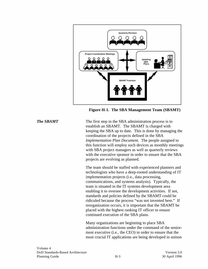
Volume 4DoD Standards-Based Architecture Version 3.0Planning Guide H-3 30 April 1996
Quarterly Reviews
Project Coordination Meetings
UpdatingSBAPlans
SBAMT Function
Figure H-1. The SBA Management Team (SBAMT)
The SBAMT The first step in the SBA administration process is toestablish an SBAMT. The SBAMT is charged withkeeping the SBA up to date. This is done by managing thecoordination of the projects defined in the SBAImplementation Plan Document. The people assigned tothis function will employ such devices as monthly meetingswith SBA project managers as well as quarterly reviewswith the executive sponsor in order to ensure that the SBAprojects are evolving as planned.
The team should be staffed with experienced planners andtechnologists who have a deep-rooted understanding of ITimplementation projects (i.e., data processing,communications, and systems analysis). Typically, theteam is situated in the IT systems development areaenabling it to oversee the development activities. If not,standards and policies defined by the SBAMT could beridiculed because the process “was not invented here.” Ifreorganization occurs, it is important that the SBAMT beplaced with the highest ranking IT officer to ensurecontinued execution of the SBA plans.
Many organizations are beginning to place SBAadministration functions under the command of the senior-most executive (i.e., the CEO) in order to ensure that themost crucial IT applications are being developed in unison
Volume 4DoD Standards-Based Architecture Version 3.0Planning Guide H-4 30 April 1996
with the organization’s strategic plan. This is highlyrecommended and represents the best case scenario.
Once established, the team must conduct a generalassessment of the SBA projects to see if, in fact, theprojects are being implemented in compliance with theoverall architecture. This is done by mapping projectprogress against the implementation plans as well by as theteam asking itself (and the responsible project managers)some hard questions like:
• Is the architecture framework still valid? Should any ofthe architecture principles be modified? Which onesand why? What has changed?
• What are the benefits to be had from changes to theimplementation plans? Are there any cost savings,value-added benefits, or softer, long-term intangiblebenefits?
• Have IT standards been materially implemented in theorganization? How far along the standards road havewe traveled thus far? How far, given this “processcheck,” do we have yet to go? Have we gleaned 80percent of the benefit already, or is there still payoffdown the road?
• Has the enterprise recognized any benefit from thework achieved?
• Given the current state of implementation, have anyother payoffs been obtained that may not have beenoriginally predicted?
• In general, do the plans and their delivery schedulesappear to be changing?
• Have any standards, targeted as important, not yetmatured as much as originally anticipated?
• What is the status of the technology that was selectedfor implementation? Has it “shown up on time” in themarketplace? Have we secured its acquisition?
After these questions have been answered, adjustments tothe original plans should be made (i.e., if a given project is

Volume 4DoD Standards-Based Architecture Version 3.0Planning Guide H-5 30 April 1996
not maturing as originally scheduled, specific steps must bedeveloped to produce “workarounds”).
Primary responsibilities • Conduct monthly project coordination meetings
• Conduct quarterly executive sponsor meetings
• Update SBA plans
• Communicate SBA changes to the stakeholdercommunity
• Review SBA project status
• Facilitate cross-project sharing of information/code
• Identify opportunities to consolidate systemsdevelopment efforts
• Assist project managers in adjusting SBA project plans
• Coordinate complimentary voice and data developmentefforts.
Executive sponsor In industry, perhaps the largest constraint in SBAimplementation work is senior management’sunwillingness to participate in the review and nurturing ofthe IT architecture. To keep SBA in the forefront ofactivities in the systems development arena, this attitudemust change.
An IT steering committee must be formed, charged withoverseeing the prioritization of SBA projects, as well asfinal approval for all changes and adjustments to the SBAproject scope and delivery schedules. This duty would beappropriate for the executive sponsor. This team of seniorofficers should be prepared to commit the necessaryresources required to make SBA a success.
Typically, the steering committee (executive sponsor)members participate in quarterly reviews of the SBAproject status and actively seek to incorporate input fromthe quarterly SBA reviews into their budget/planning (i.e.,POM) process. These decision makers assist the SBAMTin implementing the necessary changes to the SBA bycommunicating shifts in priorities to their subordinates.
In this new kind of “top-down,” “function-driven”environment, assessment and review become lesspersonally and politically charged. The result is that the

Volume 4DoD Standards-Based Architecture Version 3.0Planning Guide H-6 30 April 1996
SBAMT process becomes easier to conduct successfully.Ultimately, this form of organizational behavior leads tothe establishment of a successful and repeatableimplementation process.
Primary responsibilities • Participate in quarterly SBA reviews
• Make decisions regarding SBA project priorities andadjustments
• Oversee SBA project implementation within thefunctional areas of the enterprise.
Quarterly SBA reviews Quarterly SBA reviews are a vehicle to help executivesponsor members keep abreast of SBA progress and beaware of all the changes that occur during the SBA projectevolution. Information conveyed in these reviews shouldbe incorporated into the budgeting process within theenterprise. In this way, the enterprise will reduce thedollars being squandered on insignificant IT projects.
Also, these reviews are an important means by which theSBAMT can gain an understanding of the desires of seniorofficers (i.e., balance current priorities with newrequirements). This insight will be needed to bettermanage changes to the SBA project plans and to definenew SBA projects.
Primary objectives • Executive management review of the SBA progress
• Approval and prioritization of new SBA projects
• Approval and prioritization of changes to existing SBAplans
• Providing a means for functional areas to articulate newIT requirements.
Monthly projectcoordination meetings
Project coordination meetings are held between theSBAMT and all the SBA project managers responsible forbuilding SBA projects. These meetings are a way for theadministrators to understand the issues affecting SBAefforts, enabling them to make changes to the SBA.
Volume 4DoD Standards-Based Architecture Version 3.0Planning Guide H-7 30 April 1996
Furthermore, these meetings are used to encourage projectmanagers to discuss interproject issues, like software reuseand data integration. When this communication vehiclehits its stride, it can be used to deliver informationregarding new IT standards and policies to all projectmanagers represented in the coordination meetings.
Primary objectives • SBAMT review of SBA projects (plans and budgets)
• Announcement of adjustments in SBA plans
• Cross-project discussions on coordination issues (i.e.,data sharing, etc.)
• Delivery news on IT related issues (i.e., standardsadoption, etc.).
Communication vehicles As mentioned earlier, it is extremely important to staff theSBAMT with seasoned IT professionals. To do otherwisecan be disastrous. Team members must come to theplanning table with experience in technology planning andthe sensibilities to understand the inherent cultural andpolitical climate.
The next most important factor in conducting successfularchitecture administration is the establishment of a set ofeffective communication mechanisms that can help theadministration team distribute important information, suchas project planning documents, and receive criticalfeedback without having to become immersed in the typical“red tape” that such work usually entails.
Figure H-2 highlights this issue and suggests several waysthe Marine Corps can keep the communication lines openwhile effectively distributing valuable information aboutthe status of its SBA projects.
Quality review meetings Sometime during the first year of SBA administration, theSBAMT should develop a quality review process that willbe applied to each SBA project as it matures through thephases of the project development life cycle. This “processcheck” should conform to existing Total QualityManagement (TQM) initiatives and, as such, provide a“quality assurance” dimension to the overall architectureadministration process.

Volume 4DoD Standards-Based Architecture Version 3.0Planning Guide H-8 30 April 1996
CommunicationVehicles
StatusReports
Quality ReviewMeetings
Newsletters
E-MailBulletin Board
EISApplications
“RoadShow”
Briefings
Figure H-2. Some Important Communication Vehicles
A review process based on the Continuous ProcessImprovement Cycle (see Figure 8-1) is recommended. Thenotion is that a project is planned, work begins, the result ischecked against the plan, and opportunities forimprovement are defined and acted upon throughmodifications to the next plan (or project phase, whateverthe case may be). The use of this technique will help theenterprise learn from its SBA experiences.
Each review meeting can be used as a way for the SBAMTto communicate suggested changes in the projectdevelopment process to SBA project managers (internal aswell as external personnel), contributing to the creation ofthe “learning organization,” which is fundamental to TQMobjectives.

Volume 4DoD Standards-Based Architecture Version 3.0Planning Guide H-9 30 April 1996
Status reports Status reports are another way to improve communicationwithin the SBA development environment. Bydocumenting such things as causes of project delays orscope changes, the SBAMT can begin to define ways toproactively address them. These “lessons learned,”together with the modified plans, should be included in aquarterly SBA status report and delivered to all designatedpersonnel.
Often overlooked, documenting the “lessons learned” (seeFigure 8-4) becomes very valuable to future projectdevelopment teams, particularly when definingmodifications to SBA project plans helping future projectmanagers to “never make the same mistake twice.”
“Road shows” Another important way to inform enterprise personnelabout the significance of SBA is to establish an SBAawareness program (or “road show”). The road show willinvolve the creation of an SBA briefing that describes theSBA process and explains the impact it has on theenterprise. (See Figure H-3.)
The SBAMT will schedule briefings at all major sites. Allpersonnel would be expected to attend one of thesebriefings. Once all personnel have been exposed to theSBA project, the next phase of the awareness programwould take the form of annual status meetings delivered atthe same sites.
SBA is...
Figure H-3. The SBA “Road Show” Will Take theMessage to the Troops

Volume 4DoD Standards-Based Architecture Version 3.0Planning Guide H-10 30 April 1996
Newsletters An SBA newsletter could also be created as a means ofkeeping all personnel informed of the SBA progress. Thenewsletter could be published quarterly, and its productionshould coincide with the IT executive sponsor meetings.This way, news concerning executive managementdecisions about SBA events can be delivered to the entirecommunity.
Electronic bulletin boards An electronic bulletin board dealing with SBA subjects canbe established within the E-mail environment. (See FigureH-4.) It can become a very useful broadcast mechanism,since many personnel use it on a daily basis. In fact, manyorganizations in the commercial world use such devices asa way to solicit improvement ideas from personnel,transmit newsletters, distribute results from quarterlyreviews, and deliver project progress reports to SBAMT-like groups.
CampPendleto
nE-MailUsers
HQMCE-Mail Users
SBAMT
CampPendleto
nE-MailUsers
CampPendleto
nE-MailUsers
OkinawaE-MailUsers
CampLejeune
E-Mail Users
CampPendleto
nE-MailUsers
E-Mail UsersAt All OtherLocations
E-MAIL BULLETINBOARD
Figure H-4. The E-mail Bulletin Board Posts All SBANews for All Personnel to Access
EIS applications The development of an SBA Executive Information System(EIS) is another effective communication tool. Theprimary focus of such a system is to provide an electronicmeans of keeping senior management aware of changes inSBA projects.
Volume 4DoD Standards-Based Architecture Version 3.0Planning Guide H-11 30 April 1996
The typical EIS system is easy to use, has user-definedtriggers and a myriad of other features that make such asystem a very useful tool. (For example, each executivecan define areas of particular interest so that when one ofhis SBA projects is affected in any way, an electronicmessage is sent to his computer; similarly, other changesthat are not of interest never show up on his screen).
Architecture remodeling When should you remodel? When any of the principlesdeveloped in the architecture framework phase havechanged. Another reason could be a major change intechnology significant enough not to have been anticipatedin the target architecture phase; however, such changes willbecome increasingly rare. One of the major benefits ofstandards planning is that standards, unlike the underlyingtechnology itself, change far more slowly.
In theory, one should never have to change the architectureif the architecture principles do not change; however, theydo change from time to time. When this happens, theSBAMT should discuss and confirm the perceived changeswith the SBA executive sponsor and all IT projectmanagers before taking any action.

Volume 4DoD Standards-Based Architecture Version 3.0Planning Guide H-12 30 April 1996
This page intentionally left blank.

Volume 4DoD Standards-Based Architecture Version 3.0Planning Guide I-1 30 April 1996
Appendix I: Sample DeliverableTable of Contents
This section provides general outlines for each of thedeliverables in the SBA planning process. These may beamended and customized by the AWG for presentation tothe ASC. The individual circumstances surrounding theorganizational culture and IT environment will alsoinfluence the deliverable.
The standards-basedarchitecture
The standards-based architecture is composed of sevendeliverables, which are released on a phased basis. FigureI-1 outlines the individual components of the model.
SBAAssessmentDocument
ImplemenationPlan
DocumentMigrationOptions
DocumentOpportunityIdentification
DocumentTarget
ArchitectureDocument
BaselineCharacterization
DocumentArchitecureFrameworkDocument
The Standards-Based Architecture
Figure I-1. The Standards-Based Deliverable Set
Staged deliverablesthroughout the process
A key aspect of the standards-based planning process is themanner in which the architecture is developed. It isrecommended that at each phase of the planning process aninterim deliverable be produced by the team. Figure I-2illustrates the phases and their associated deliverables.
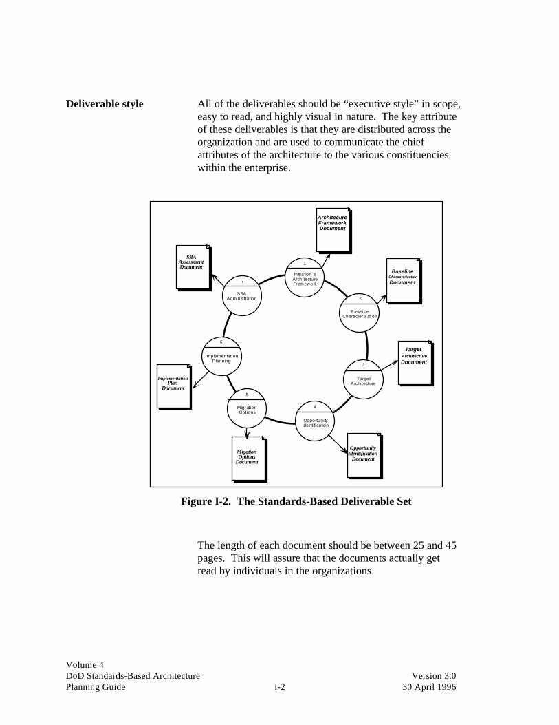
Volume 4DoD Standards-Based Architecture Version 3.0Planning Guide I-2 30 April 1996
Deliverable style All of the deliverables should be “executive style” in scope,easy to read, and highly visual in nature. The key attributeof these deliverables is that they are distributed across theorganization and are used to communicate the chiefattributes of the architecture to the various constituencieswithin the enterprise.
ArchitecureFrameworkDocument
BaselineCharacterization
Document
TargetArchitectureDocument
4
Opportuni tyIdenti fication
1
Initiation &ArchitectureFr amework
5
Migr ationOptions
6
ImplementationP lanning
7
SBAAdministration
3
TargetA rchitecture
2
BaselineCharacter ization
OpportunityIdentification
DocumentMigationOptions
Document
ImplementationPlan
Document
SBAAssessmentDocument
Figure I-2. The Standards-Based Deliverable Set
The length of each document should be between 25 and 45pages. This will assure that the documents actually getread by individuals in the organizations.

Volume 4DoD Standards-Based Architecture Version 3.0Planning Guide I-3 30 April 1996
Architecture FrameworkDocument
SAMPLE TABLE OF CONTENTS
I. Executive summary
- Project status
- Key issues
II. Key functional drivers and issues
III. Key interview findings
IV. IT principles constitution
V. Architecture planning issues
- Functional technology issues
- IT description: current environment
- Security issues
- Cost/benefit design concerns
VI. Functional and information opportunities
VII. Design issues
- Design principles, guidelines, andimplications
- Design alternatives review
- SBA design attributes
VIII. Next steps

Volume 4DoD Standards-Based Architecture Version 3.0Planning Guide I-4 30 April 1996
BaselineCharacterizationDocument
SAMPLE TABLE OF CONTENTS
I. Executive summary
- Project status
- Key issues
II. Key architecture baseline characterization issues
III. Scope and approach
IV. Classification and description
- Platform classification
- Generic application model
- Generic technology model
- Work flow model
- Generic information model
- Standards support description
- Security evaluation
- Connectivity support model
- Cost/performance data
V. Summary assessment of design issues andconstraints of current environment
VI. Implications for target architecture design
VII. Next steps

Volume 4DoD Standards-Based Architecture Version 3.0Planning Guide I-5 30 April 1996
Target ArchitectureDocument
SAMPLE TABLE OF CONTENTS
I. Executive summary
- Project status
- Key issues
II. Target architecture description
- Work flow and processes
- Data and information
- Applications
- Technology platforms
- Standards
- Migration issues
- Architecture organization and personnelissues
III. Architecture design alternatives
IV. Procurement issues
V. Implementation issues
VI. Next steps

Volume 4DoD Standards-Based Architecture Version 3.0Planning Guide I-6 30 April 1996
OpportunityIdentification Document
SAMPLE TABLE OF CONTENTS
I. Executive summary
- Project status
- Key issues
II. Implementation opportunity identification
- Strategic opportunities
- Major opportunities
- Quick hits
- General benefit and business case
- Magnitude, payoff, and degrees of freedomclassification
III. Overall benefit classification
IV. Next steps

Volume 4DoD Standards-Based Architecture Version 3.0Planning Guide I-7 30 April 1996
Migration OptionsDocument
SAMPLE TABLE OF CONTENTS
I. Executive summary
- Project status
- Key issues
II. General cost/benefit definition
III. Migration project scope definition
IV. Technology standard implementation strategy
V. Time lines and trigger points
VI. Project cost and time frame considerations
VII. Specific business case and cost/benefit analysisfor identified opportunities
VIII. Project deliverables definition
IX. Organizational change process requirements
X. Next steps

Volume 4DoD Standards-Based Architecture Version 3.0Planning Guide I-8 30 April 1996
Implementation PlanDocument(s)
This is not a formal presentation document, rather it is theaggregate set of project plan documents produced by theindividual functional unit.
Presented below is a suggested set of topic areas to includein each plan. These may vary widely depending upon theimplementation project but should comply with all DoDproject management standards.
I. Project description
II. Objectives
III. Scope
IV. Deliverables
V. Critical success factors
VI. Constraints
VII. Task list
VIII. Effectiveness measures
IX. Technology requirements
X. Staffing skills
XI. Completion criteria
XII. Other issues

Volume 4DoD Standards-Based Architecture Version 3.0Planning Guide I-9 30 April 1996
SBA AssessmentDocument
SAMPLE TABLE OF CONTENTS
I. Executive summary
- Project status
- Key issues
II. Scope of architecture review
III. Key review findings
IV. Implementation adherence to IT principles andtarget architecture
- Processes
- Information
- Platforms
- Standards
- Migration issues
- Architecture organization and personnelissues
V. User views of benefits and functionalitydelivered
VI. Review of cost/benefit implementationdelivered
VII. Continuous process improvementrecommendations
VIII. Next steps

Volume 4DoD Standards-Based Architecture Version 3.0Planning Guide I-10 30 April 1996
This page intentionally left blank.

Volume 4DoD Standards-Based Architecture Version 3.0Planning Guide J-1 30 April 1996
Appendix J: Glossary
American National Standards Institute (ANSI): The principal standards coordinationbody in the United States. ANSI is a member of the International Organization forStandardization (ISO).
Application: The use of capabilities (services and facilities) provided by an informationsystem specific to the satisfaction of a set of user requirements. [P1003.0/D15]
Application Entity: The part of an application process that interacts with anotherapplication process.
Application Layer: Layer seven of the OSI Reference Model. It serves as a windowthrough which applications access communication services.
Application Model: A term used to describe those functions of an organization that canbe supported or automated through IT. It is used for grouping or clustering functionsinto applications. It provides the application developers’ views of the IT architecture.
Application Process: The part of an application that resides in a single end system.
Architecture: Architecture has various meanings depending upon its contextual usage.(1) The structure of components, their interrelationships, and the principles andguidelines governing their design and evolution over time. [IEEE STD 610.12](2) Organizational structure of a system or component. [IEEE STD 610.12](3)The disciplined definition of the IT infrastructure required by a business to attain itsobjectives and achieve a business vision. It is the structure given to information,applications, and organizational and technological means—the groupings of components,their interrelationships, the principles and guidelines governing their design, and theirevolution over time.
Bridge: The hardware and software used to connect circuits and equipment in twonetworks with the same protocol.
Common Applications Environment (CAE): The X/Open term for a computerenvironment in which applications can be ported across X/Open vendor systems. Itincludes standards for the operating system, languages, networking protocols, and datamanagement.
Computer-Aided Acquisition and Logistics Support (CALS): Standards for electronic fileformat interchange and data management adopted by the U.S. Department of Defense toacquire, process, and disseminate technical information in digital form. CALS willfacilitate the transfer of logistic and technical information between industry andGovernment by leveraging existing international standards. Among the industry

Volume 4DoD Standards-Based Architecture Version 3.0Planning Guide J-2 30 April 1996
standards used in CALS are IGES (CAD, vector graphics), SGML (automatedpublishing), GRP 4 Raster or TRIF (raster scanned images), and CGM (illustrations).
Computer-Aided Software Engineering (CASE): A set of software tools that automateand contribute to the improvement of the software development process.
Conformance: Meeting standards. By running standard test scripts, conformance testingensures that a product meets standards.
Connection: In data communications terminology, a logical link established betweenapplication processes that enables them to exchange information. In the OSI ReferenceModel, an association established by one layer with two or more entities of the nexthigher layer for the transfer of data. In TCP/IP, it is a logical TCP communication pathidentified by a pair of sockets, one for each side of the path.
Data Link: An assembly of two or more terminal installations and an interconnectingline.
Data Link Layer: Layer two of the OSI Reference Model. It controls the transfer ofinformation between nodes over the physical layer.
Directory Services: A service of the External Environment entity of the TechnicalReference Model that provides locator services that are restricted to finding the locationof a service, location of data, or translation of a common name into a network specificaddress. It is analogous to telephone books and supports distributed directoryimplementations. [TA]
Distributed System: A system consisting of a group of connected, cooperatingcomputers.
Distribution List: A list containing the names of mail users and/or other distribution lists.It is used to send the same message to multiple mail users. It can be private or public.
Electronic Mail: The electronic generation, transmission, and display of correspondenceand documents. Electronic mail is a GAE.
Entity: An active element within an open system layer (e.g., session entity, transportentity). It can represent one layer, one part of a layer, or several layers of the OSIReference Model. One layer can include several entities.
Exterior Gateway Protocol (EGP): The service by which gateways exchangeinformation about what systems they can reach.
Gateway: A device for converting one network’s message protocol to the format used byanother network’s protocol. It can be implemented in hardware or software.
Generic Application Environment (GAE): A term used to describe the set of architecturecomponents that describe the different possible types of IT applications.

Volume 4DoD Standards-Based Architecture Version 3.0Planning Guide J-3 30 April 1996
Generic Technology Environment (GTE): A term used to describe the set of architecturecomponents that describe the different types of services required to support a GAE.
Generic Technology Platform (GTP): A term used to describe the different types ofdelivery components that can be used to support IT applications.
Government Open Systems Interconnection Profile (GOSIP): A government (e.g., U.S.or U.K.) profile of functional applications that outlines a national policy and strategy forconverting to a communications system based on OSI. Use of GOSIP is no longermandatory.
Host: A computer, particularly a source or destination of messages, on acommunications network.
Information Model: A term used to describe the information resources of theorganization and their interrela-tionships. It is used to support data modeling andresulting database and document storage design requirements. It provides theinformation resource managers’ views of the architecture.
Institute of Electrical and Electronics Engineers (IEEE): An accredited standards bodythat has produced standards such as the network-oriented 802 protocols and POSIX.Members represent an international cross section of users, vendors, and engineeringprofessionals.
Integrated Services Digital Network (ISDN): The recommendation published by CCITTfor private or public digital telephone networks where binary data, such as graphics anddigitized voice, travel over the same lines. ISDN will unite voice and data transmission,including imaging, over the same kind of digital network that links most telephonetransmissions in use today.
Interface: A connecting link between two systems. In the OSI Reference Model, it is theboundary between adjacent layers.
International Standard (IS): Agreed international standard as voted by ISO.
International Organization for Standardization (ISO): An organization that establishesinternational standards for computer network architecture. Its OSI Reference Modeldivides network functions into seven layers. (Membership is by country, with more than90 countries currently participating.)
Interoperability: (1) The ability of two or more systems or components to exchange anduse information. [IEEE STD 610.12]. (2) The ability of the systems, units, or forces toprovide and receive services from other systems, units, or forces, and to use the servicesso interchanged to enable them to operate effectively together. The conditions achievedamong communications-electronics systems or items of communications-electronicsequipment when information or services can be exchanged directly and satisfactorilybetween them and/or their users. [Joint Pub 1-02, DoD/NATO] [JOPES ROC]

Volume 4DoD Standards-Based Architecture Version 3.0Planning Guide J-4 30 April 1996
(2)The ability of applications and computers from different vendors and architectures towork together on a network.
Interoperability Testing: Procedures for ensuring that a computer product or system cancommunicate in a multivendor network.
Layer: A level of the OSI Reference Model. The model divides functions fortransferring information between systems into seven layers, grouping the relatedfunctions or tasks and making them easier to understand. Each layer performs certaintasks to move the information from sender to receiver. Protocols within the layers definethe tasks for networks but not how the software accomplishes the tasks. Interfaces passinformation between the layers they connect.
Local Area Network (LAN): A data network, located on a user’s premises, within alimited geographic region. Communication within a local area network is not subject toexternal regulation; however, communication across the network boundary may besubject to some form of regulation. [FIPS PUB 11-3]
Message: A block of information sent from a source to one or more destinations.
MS-DOS: The personal computer operating system developed by Microsoft Corporation.
Multivendor Network: A computer network with hardware and software from more thanone vendor.
National Institute for Standards and Technology (NIST): The division of the U.S.Department of Commerce that ensures standardization within Government agencies.NIST is responsible for the Applications Portability Profile—a set of standards andguidelines for U.S. Government procurement. NIST was formerly known as theNational Bureau of Standards (NBS).
Network: A system of connected computers.
Network Layer: The third layer of the OSI Reference Model. This layer controlsunderlying telecommunication functions such as routing, relaying, and data linkconnections.
Node: A point in a network, either at the end of a communication line (end node) orwhere two lines meet (intermediate node).
Open Network: A network that can communicate with any system component(peripherals, computers, or other networks) implemented to the international standard(without special protocol conversions, such as gateways).
Open Software Foundation (OSF): An organization created by major IT vendors todefine specifications, develop software, and make available an open, portableenvironment.
Volume 4DoD Standards-Based Architecture Version 3.0Planning Guide J-5 30 April 1996
Open Systems: (1) A system that implements sufficient open specifications forinterfaces, services, and supporting formats to enable properly engineered applicationssoftware: (a) to be ported with minimal changes across a wide range of systems, (b) tointeroperate with other applications on local and remote systems, and (c) to interact withusers in a style that facilitates user portability. [P1003.0/D15] (2) Softwareenvironments consisting of products and technologies that are designed and implementedin accordance with “standards” (established and de facto) that are vendor independentand commonly available.
Open Systems Interconnection (OSI): A set of standards that, when implemented, letdifferent computer systems communicate with each other.
Operating System: A group of programs operating under the control of a data processingmonitor program. It manages such functions as memory, processing tasks, andinterprocess communication in a computer system.
OSI Reference Model: The seven-layer model, defined by the ISO, that provides theframework for building an open network. The seven layers, ranging from highest tolowest, are application, presentation, session, transport, network, data link, and physical.
Password: A string of characters required to gain access to directories, files, orapplications.
Peer Protocol: The protocol governing communications between program entities thathave the same function in the same layer in each of two OSI networks.
Physical Layer: The first layer of the OSI Reference Model. It governs hardwareconnectors and byte-stream encoding for transmission. It is the only layer that involves aphysical transfer of information between network nodes.
Portable Operating System Interface for Computer Environments (POSIX): An IEEEstandard operating-system interface defining the external characteristics and facilitiesrequired to achieve the portability of applications at the source-code level.
Portability: (1) The ease with which a system or component can be transferred from onehardware or software environment to another. [IEEE STD 610.12] (2) A quality metricthat can be used to measure the relative effort to transport the software for use in anotherenvironment or to convert software for use in another operating environment, hardwareconfiguration, or software system environment. [IEEE TUTOR] (3) The ease withwhich a system, component, data, or user can be transferred from one hardware orsoftware environment to another. [TA]
Porting: The process by which a software application is made operational on a computerarchitecture different from the one on which it was originally created.
Presentation Layer: The sixth layer of the OSI Reference Model. It allows anapplication to properly interpret the data being transferred.
Process: A general term for any computer operation on data.

Volume 4DoD Standards-Based Architecture Version 3.0Planning Guide J-6 30 April 1996
Profile: A set of one or more base standards, and, where applicable, the identification ofthose classes, subsets, options, and parameters of those base standards, necessary foraccomplishing a particular function. [P1003.0/D15]
Protocol: A set of rules governing network functionality. The OSI Reference Modeluses sets of communication protocols to facilitate communication between computernetworks and their components.
Quality of Service (QOS): A set of characteristics of a connection as observed betweenthe connection end points. In the OSI session and transport layers, acceptable QOSvalues are negotiated between the service users when the connection is established.
Scalability: The ability to use the same application software on many different classes ofhardware/software platforms from personal computers to super computers (extends theportability concept). [USAICII] The capability to grow to accommodate increased workloads.
Server Type: A class of servers in a client/server architecture.
Service Provider: The resource that provides the facilities of the relevant OSI ReferenceModel layer. The OSI session and transport layers are the service providers for thesession and transport services, and the X.25 network gateway or X.25 message controlsystem is the service provider for the network service.
Service User: The software application using the facilities of one of the layers of the OSIReference Model. For example, a program that calls the programmatic interface to thesession layer is a session service user.
Session Layer: The sixth layer of the OSI Reference Model. It provides the means fortwo session service users to organize and synchronize their dialogues and manage theexchange of data.
Store-and-Forward Message System: The communication process that allows messagesto be stored at intermediate nodes before being forwarded to their destination. X.400defines a message handling system that uses this process.
System:–People, machines, and methods organized to accomplish a set of specificfunctions. [FIPS PUB 11-3]
TCP/IP Gateway: A device, or pair of devices, that interconnects two or more networksor subnetworks, enabling the passage of data from one (sub)network to another. In thisarchitecture, a gateway contains an IP module and, for each connected subnetwork, asubnetwork protocol (SNP) module. The routing protocol is used to coordinate withother gateways. A gateway is often called an IP router.
Technology Model: A term used to define and describe the components of thetechnology infrastructure that support the other architecture models. It is in this area that

Volume 4DoD Standards-Based Architecture Version 3.0Planning Guide J-7 30 April 1996
the enabling effect of standards-based architectures is felt the most. The technologymodel provides the technology managers’ views of the architecture.
UniForum: A trade association dedicated to promoting UNIX and open systems.UniForum sponsors UNIX events, publishes magazines, directories and technicaloverviews, and proposes specifications.
UNIX: An operating system that has become a de facto industry standard, supported on awide range of hardware systems from a variety of vendors.
UNIX International: The consortium that defines and promotes the UNIX operatingsystem and related software products.
Wide-Area Network (WAN): A public or private computer network serving a widegeographic area.
Work Organization Model: A term used to describe the impact on business operations atthe work group and user
levels. It is used by organizational change designers to manage the impact of introducingnew IT systems. It provides the users’ views of the architecture.
X.25: Recommendations developed by CCITT that define a protocol for communicationbetween packet-switched public data networks and user devices in the packet-switchedmode.
X.400: The international standard for a store-and-forward message handling system in amultivendor environment.
X/Open Company Ltd.: A nonprofit corporation made up of vendors and large corporateusers who are investing in the specification of the X/Open Portability Guide (XPG), anopen environment based on standards. X/Open also brands products.

Volume 4DoD Standards-Based Architecture Version 3.0Planning Guide J-8 30 April 1996
This page intentionally left blank.

Volume 4DoD Standards-Based Architecture Version 3.0Planning Guide K-1 30 April 1996
Appendix K: Proposing Changes toTAFIM Volumes
Introduction Changes to the TAFIM will occur through changes to theTAFIM documents (i.e., the TAFIM numbered volumes,the CMP, and the PMP). This appendix provides guidancefor submission of proposed TAFIM changes. Theseproposals should be described as specific wording forline-in/line-out changes to a specific part of a TAFIMdocument.
Use of a standard format for submitting a change proposalwill expedite the processing of changes. The format forsubmitting change proposals is shown below. Guidance onthe use of the format is subsequently provided.
A Configuration Management contractor is managing thereceipt and processing of TAFIM change proposals. Thepreferred method of proposal receipt is via e-mail in ASCIIformat, sent via the Internet. If not e-mailed, the proposedchange, also in the format shown below, and on both paperand floppy disk, should be mailed. As a final option,change proposals may be sent via fax; however, deliverymethods that enable electronic capture of change proposalsare preferred. Address information for the ConfigurationManagement contractor is shown below.
Internet: [email protected]
Mail: TAFIMBooz•Allen & Hamilton Inc.5201 Leesburg Pike, 4th FloorFalls Church, VA 22041
Fax: 703/671-7937; indicate “TAFIM” on coversheet.

Volume 4DoD Standards-Based Architecture Version 3.0Planning Guide K-2 30 April 1996
TAFIM Change ProposalSubmission Format
a. Point of Contact Identification
(1) Name:
(2) Organization and Office Symbol:
(3) Street:
(4) City:
(5) State:
(6) Zip Code:
(7) Area Code and Telephone #:
(8) Area Code and Fax #:
(9) E-mail Address:
b. Document Identification
(1) Volume Number :
(2) Document Title:
(3) Version Number:
(4) Version Date:
c. Proposed Change # 1
(1) Section Number:
(2) Page Number:
(3) Title of Proposed Change:
(4) Wording of Proposed Change:
(5) Rationale for Proposed Change:
(6) Other Comments:
d. Proposed Change # 2
(1) Section Number:
(2) Page Number:

Volume 4DoD Standards-Based Architecture Version 3.0Planning Guide K-3 30 April 1996
(3) Title of Proposed Change:
(4) Wording of Proposed Change:
(5) Rationale for Proposed Change:
(6) Other Comments:
n. Proposed Change # n
(1) Section Number:
(2) Page Number:
(3) Title of Proposed Change:
(4) Wording of Proposed Change:
(5) Rationale for Proposed Change:
(6) Other Comments:
Format Guidance The format should be followed exactly as shown. Forexample, Page Number should not be entered on the sameline as the Section Number. The format can accommodate,for a specific TAFIM document, multiple change proposalsfor which the same individual is the Point of Contact(POC). This POC would be the individual the TAFIMproject staff could contact on any question regarding theproposed change. The information in the Point of ContactIdentification part (a) of the format would identify thatindividual. The information in the DocumentIdentification part of the format (b) is self-evident, exceptthat volume number would not apply to the CMP or PMP.The proposed changes would be described in the ProposedChange # parts (c, d, or n) of the format.
In the Proposed Change # parts of the format, the Sectionnumber refers to the specific subsection of the document inwhich the change is to take place (e.g., Section 2.2.3.1).The page number (or numbers, if more than one page isinvolved) will further identify where in the document theproposed change is to be made. The Title of ProposedChange field is for the submitter to insert a brief title thatgives a general indication of the nature of the proposedchange. In the Wording of Proposed Change field thesubmitter will identify the specific words (or sentences) to

Volume 4DoD Standards-Based Architecture Version 3.0Planning Guide K-4 30 April 1996
be deleted and the exact words (or sentences) to beinserted. In this field providing identification of thereferenced paragraph, as well as the affected sentence(s) inthat paragraph, would be helpful. An example of input forthis field would be: “Delete the last sentence of the secondparagraph of the section and replace it with the followingsentence: ‘The working baseline will only be available tothe TAFIM project staff.’” The goal is for the commentorto provide proposed wording that is appropriate forinsertion into a TAFIM document without editing (i.e., aline-out/line-in change). The c (5), d (5), or n (5) entry inthis part of the format is a discussion of the rationale forthe change. The rationale may include reference material.Statements such as “industry practice” would carry lessweight than specific examples. In addition, to the extentpossible, citations from professional publications should beprovided. A statement of the impact of the proposedchange may also be included with the rationale. Finally,any other information related to improvement of thespecific TAFIM document may be provided in c (6), d (6),or n (6) (i.e., the Other Comments field). However,without some degree of specificity these comments maynot result in change to the document.