Embed Size (px)
Citation preview

NOT
MEASUREMENT
SENSITIVE
MIL-STD-188-110C
w/CHANGE 1
3 JANUARY 2012
SUPERSEDING
MIL-STD-188-110C
23 SEPTEMBER 2011
DEPARTMENT OF DEFENSE
INTERFACE STANDARD
INTEROPERABILITY AND PERFORMANCE STANDARDS
FOR DATA MODEMS
AMSC N/A AREA TCSS
DISTRIBUTION STATEMENT A: Approved for public release; distribution unlimited.
Downloaded from http://www.everyspec.com

MIL-STD-188-110C
w/CHANGE 1
ii
FOREWORD
1. This Military Standard is approved and mandatory for use by all Departments and Agencies
of the Department of Defense (DoD) in accordance with Joint Technical Architecture (JTA)
Version 6, dated 3 October 2003.
2. This document contains technical standards and design objectives for minimum interface and
performance standards pertinent to voice frequency band modulators-demodulators (modems)
which operate in both long-haul and tactical communications systems. The terms "system
standard" and "design objective (DO)" are defined in FED-STD-1037. In this document, the
word "shall" identifies mandatory system standards. The word “should” identifies DOs that are
desirable but not mandatory.
3. Comments, suggestions, or questions on this document should be addressed to Oklahoma City
Air Logistics Center (OC-ALC)/ENSDAA, 3001 Staff Drive, Tinker AFB, OK 73145 or e-
mailed to [email protected]. Since contact information can change, you may want to verify the
currency of this address information using the ASSIST Online database at
https://assist.daps.dla.mil.
Downloaded from http://www.everyspec.com

MIL-STD-188-110C
w/CHANGE 1
iii
SUMMARY OF CHANGE 1 MODIFICATIONS
1. Paragraph D.5.4. Removed sentence "The reinserted preamble facilitates acquisition (or re-
acquisition) of an ongoing broadcast transmission." That refers to a feature that is obsolete.
2. Changed title of TABLE D-LII from “Data performance requirements, All Bandwidths” to
"Data performance requirements, 3, 6, 9, 12, and 24 kHz Bandwidths" for clarification purposes.
Downloaded from http://www.everyspec.com
MIL-STD-188-110C
w/CHANGE 1
iv
3. TABLE OF CONTENTS
TITLE PAGE
1 SCOPE ................................................................................................................................................... 1
1.1 Scope. .............................................................................................................................................. 1
1.2 Applicability. ................................................................................................................................... 1
1.3 Application guidance. ..................................................................................................................... 1
2 APPLICABLE DOCUMENTS ........................................................................................................... 2
2.1 Government documents. ................................................................................................................. 2
2.1.1 Specifications and standards. .......................................................................................................... 2
2.1.2 Other Government documents and publications. .......................................................................... 3
2.2 Non-government publications. ....................................................................................................... 3
2.3 Order of precedence. ....................................................................................................................... 3
3 DEFINITIONS ...................................................................................................................................... 4
3.1 Terms. .............................................................................................................................................. 4
3.2 Abbreviations and acronyms. ......................................................................................................... 5
4 GENERAL REQUIREMENTS ......................................................................................................... 10
4.1 Functional employment. ............................................................................................................... 10
4.2 Common parameters. .................................................................................................................... 10
4.2.1 Modulation and data signaling rates and tolerance. ..................................................................... 10
4.2.2 Logic and signaling sense for binary signals. .............................................................................. 11
4.2.3 Digital interface characteristics..................................................................................................... 12
4.2.4 Terminal impedance for quasi-analog signals. ............................................................................ 12
4.2.4.1 Modems used in single-channel radio subsystems. ........................................................... 12
4.2.4.2 Quasi-analog signal levels. ................................................................................................. 13
4.2.5 Clock equipment, control, and timing. ......................................................................................... 13
4.2.5.1 Transmission modes. .......................................................................................................... 13
4.2.5.2 Clock characteristics. .......................................................................................................... 13
4.2.5.2.1 Modulation rates. .......................................................................................................... 13
4.2.5.2.2 Modulation rate stability. ............................................................................................. 13
4.2.5.2.3 Modulation rate phase adjustment. .............................................................................. 13
4.2.5.2.4 Output signal. ............................................................................................................... 14
4.2.5.2.5 Clock period. ................................................................................................................ 14
4.2.5.3 Clock/data phase relationship. ............................................................................................ 14
4.3 General design requirements. ....................................................................................................... 15
4.3.1 Federal maritime interoperability requirements. ......................................................................... 15
4.3.2 International interoperability requirements. ................................................................................. 15
4.3.2.1 Shore-to-ship broadcast systems. ....................................................................................... 15
4.3.2.2 Maritime air communications systems. ............................................................................. 15
4.3.2.3 Radio teletypewriter systems. ............................................................................................. 15
4.4 Data link protocol (optional). ....................................................................................................... 15
Downloaded from http://www.everyspec.com

MIL-STD-188-110C
w/CHANGE 1
v
5 DETAILED REQUIREMENTS ........................................................................................................ 16
5.1 Frequency shift keying (FSK) modems for single-channel radio equipment. ........................... 16
5.1.1 Narrow-shift FSK modem. ........................................................................................................... 16
5.1.2 Wide-shift FSK modem. ............................................................................................................... 16
5.2 FSK data modems for voice frequency (VF) channel operation (withdrawn). ......................... 16
5.3 HF data modems. .......................................................................................................................... 16
5.3.1 General requirements. ................................................................................................................... 16
5.3.1.1 Capability. ........................................................................................................................... 17
5.3.1.2 Voice digitization. ............................................................................................................... 17
5.3.1.3 Optional modes. .................................................................................................................. 17
5.3.1.4 Interface requirements. ....................................................................................................... 18
5.3.1.4.1 Line-side data characteristics. ...................................................................................... 18
5.3.1.4.2 LAN interface (DO). .................................................................................................... 18
5.3.1.4.3 Equipment side characteristics (informative). ............................................................ 18
5.3.1.4.4 Transmit override. ........................................................................................................ 18
5.3.1.4.5 Buffering in synchronous serial mode. ....................................................................... 18
5.3.1.5 Remote control interface. ................................................................................................... 18
5.3.1.5.1 Electrical interface. ....................................................................................................... 18
5.3.1.5.2 Optional modem control driver. .................................................................................. 18
5.3.2 Serial (single-tone) mode. ............................................................................................................. 18
5.3.2.1 General. ............................................................................................................................... 18
5.3.2.2 Sequencing of time phases. ................................................................................................ 19
5.3.2.2.1 Synchronization (sync) preamble phase. .................................................................... 21
5.3.2.2.2 Data phase..................................................................................................................... 24
5.3.2.2.3 EOM phase. .................................................................................................................. 25
5.3.2.2.4 FEC coder and interleaver flush phase. ....................................................................... 25
5.3.2.3 Functional descriptions. ...................................................................................................... 25
5.3.2.3.1 EOM sequence. ............................................................................................................ 25
5.3.2.3.2 Interleaver flush ............................................................................................................ 25
5.3.2.3.3 FEC encoder. ................................................................................................................ 25
5.3.2.3.4 Interleave load. ............................................................................................................. 28
5.3.2.3.5 Interleave fetch. ............................................................................................................ 29
5.3.2.3.6 Modified-Gray decoder. ............................................................................................... 30
5.3.2.3.7 Symbol formation......................................................................................................... 31
5.3.2.3.8 Scrambler. ..................................................................................................................... 36
5.3.2.3.9 PSK modulation. .......................................................................................................... 37
5.3.2.4 Waveform summary. .......................................................................................................... 38
5.3.2.5 Performance requirements. ................................................................................................. 38
5.3.3 Frequency hopping mode (optional). ........................................................................................... 39
5.3.4 Robust serial tone mode for severely degraded HF links (optional). ......................................... 39
6 NOTES ................................................................................................................................................ 39
6.1 Intended use. ................................................................................................................................. 39
6.2 Issue of Department of Defense Index of Specifications and Standards (DODISS). ............... 40
6.3 Subject term (key word) listing. ................................................................................................... 40
Downloaded from http://www.everyspec.com

MIL-STD-188-110C
w/CHANGE 1
vi
LIST OF FIGURES
FIGURE 1. STANDARD INTERFACE BETWEEN DATA TERMINAL EQUIPMENT AND
DATA CIRCUIT-TERMINATING EQUIPMENT. ....................................................................... 12
FIGURE 2. SERIAL (SINGLE-TONE) WAVEFORM FUNCTIONAL BLOCK DIAGRAM ....... 20
FIGURE 3 AN EXAMPLE OF EQUIPMENT INTERFACE BLOCK DIAGRAM. ........................ 22
FIGURE 4 FEC ENCODER BLOCK DIAGRAM ............................................................................... 27
FIGURE 5. STATE CONSTELLATION DIAGRAM .......................................................................... 35
FIGURE 6. RANDOMIZING SHIFT REGISTER FUNCTIONAL DIAGRAM ............................... 37
LIST OF TABLES
TABLE I. REFERENCE LIST FOR MODEM APPLICATIONS. ...................................................... 10
TABLE II. LOGIC AND SIGNAL SENSE FOR BINARY SIGNALS. .............................................. 11
TABLE III. CHARACTERISTIC FREQUENCIES OF FSK DATA MODEMS FOR
SINGLE-CHANNEL RADIO EQUIPMENT. ................................................................................ 16
TABLE IV. ERROR CORRECTING CODING, FREQUENCY HOPPING OPERATION. ............ 26
TABLE V. ERROR-CORRECTING CODING, FIXED FREQUENCY OPERATION. ................... 28
TABLE VI. INTERLEAVER MATRIX DIMENSIONS. ..................................................................... 29
TABLE VII. BITS-PER-CHANNEL SYMBOL. ................................................................................... 30
TABLE VIII. MODIFIED-GRAY DECODING AT 2400 BPS AND 4800 BPS. ............................... 31
TABLE IX. MODIFIED-GRAY DECODING AT 75 BPS (FIXED FREQUENCY) AND
1200 BPS. ........................................................................................................................................... 31
TABLE X. CHANNEL SYMBOL MAPPING FOR 75 BPS. .............................................................. 33
TABLE XI. ASSIGNMENT OF DESIGNATION SYMBOLS D1 AND D2. .................................... 34
TABLE XII. CONVERSION OF TWO BIT COUNT VALUE TO THREE BIT SYMBOL. ........... 34
TABLE XIII. CHANNEL SYMBOL MAPPING FOR SYNC PREAMBLE. .................................... 36
TABLE XIV. FREQUENCY-HOPPING OPERATION WAVEFORM CHARACTERISTICS. ..... 38
TABLE XV. FIXED-FREQUENCY OPERATION WAVEFORM CHARACTERISTICS. ............ 38
TABLE XVI. SERIAL (SINGLE-TONE) MODE MINIMUM PERFORMANCE. ........................... 39
Downloaded from http://www.everyspec.com

MIL-STD-188-110C
w/CHANGE 1
1
1. SCOPE
1.1 Scope.
This document establishes mandatory technical standards and design objectives (DO) that are
necessary to ensure interoperability and to promote performance among data modulators-
demodulators (modems) used in the voice frequency (VF) band of long-haul and tactical
communications systems. This document also provides guidance to the designers of new data
modems that incorporate characteristics not yet standardized by specifying the technical
characteristics of data modems currently in the inventory. The purpose of this guidance is to
ensure attainment of minimum acceptable performance and maximum interoperability between
existing and future data modems with specified transmission channel conditions.
1.2 Applicability.
These standards are mandatory within the Department of Defense (DoD) in the design,
development and engineering of new communications facilities for both narrowband and
wideband long-haul and tactical systems. In some cases, reference is made to other documents
that provide standards for specific applications. It is not intended that existing systems be
immediately converted to comply with the requirements of these standards. New systems, and
those undergoing major modification or rehabilitation, conformance to these standards is subject
to current procurement regulations. This document is applicable to the design and development
of new data modems with standard data signaling rates up to and including 120,000 bits per
second (bps) used in long-haul and tactical communications systems. This document is not
applicable to high frequency (HF) data modems used in the Tactical Digital Information Link
(TADIL) A. The HF data modem standards for TADIL A are published in MIL-STD-188-203-1.
1.3 Application guidance.
Requirements in this document, if applied as intended, ensure the interoperability and
performance of data modems having the same or similar functions. The variety of data modems
is limited to that which are essential to effectively support the missions of the military forces. It
is not intended that the standards contained in this document inhibit advances in communications
technology. Such advances are encouraged by including DOs that should be used if economically
feasible. Additionally, standardizing parameter values but not the technology that may be used to
meet these parameter values facilitates such advances. Minimum performance requirements for
the high frequency (HF) serial (single-tone) modem waveforms are specified in Table XVI and
Appendices B, C, D, and F. The specified values shown represent HF modem performance under
ideal test conditions. To identify the minimum acceptable performance available to users, many
factors, including operational test and evaluation must be considered.
Downloaded from http://www.everyspec.com

MIL-STD-188-110C
w/CHANGE 1
2
2. APPLICABLE DOCUMENTS
2.1 General. The documents listed in this section are specified in sections 3, 4, or 5 of this
standard. This section does not include documents cited in other sections of this standard or
recommended for additional information or as examples. While every effort has been made to
ensure the completeness of this list, document users are cautioned that they must meet all
specified requirements of documents cited in sections 3, 4, or 5 of this standard, whether or not
they are listed.
2.2 Government documents.
2.2.1 Specifications and standards, and handbooks. The following specifications and standards
form a part of this document to the extent specified herein. Unless otherwise specified, the issues
of these documents are those listed in the solicitation or contract.
INTERNATIONAL STANDARDIZATION AGREEMENTS
STANAG 4197 Modulation and Coding Characteristics That Must Be Common
to Assure Interoperability of 2400 BPS Linear Predictive
Encoded Digital Speech Transmitted over HF Radio Facilities
STANAG 4198 Parameters and Coding Characteristics That Must Be Common
to Assure Interoperability of 2400 BPS Linear Predictive
Encoded Digital Speech
STANAG 4203 Technical Standard for Single Channel HF Radio Equipment
STANAG 4285 Characteristics of 1200/2400/3600 bps Single Tone
Modulators/Demodulators for HF Radio Links
STANAG 4291 Modulation and Coding Characteristics That Must Be Common
to Assure Interoperability of 2400 BPS Wireline Modems for
Use in Narrow-Band Secure Voice Systems
STANAG 4415 Characteristics of a Robust, Non-hopping Serial Tone
Modulator/Demodulator for Severely Degraded HF Radio Links
STANAG 4529 Characteristics of Single-Tone Modulators/Demodulators for
Maritime HF Radio Links with 1240 Hz bandwidth
STANAG 4481 Minimum Technical Standards for Naval HF Shore-To-Ship
Broadcast Systems
STANAG 4591
The 600 Bit/s, 1200 Bit/s, and 2400 Bit/s NATO Interoperable
Narrow Band Voice Coder
Downloaded from http://www.everyspec.com

MIL-STD-188-110C
w/CHANGE 1
3
STANAG 5066
Profile For HF Radio Data Communications
FEDERAL STANDARDS
FED-STD-1035 Coding, Modulation and Transmission Requirements for Single
Channel Medium and High Frequency Radiotelegraph Systems
Used in Government Maritime Mobile Telecommunications
FED-STD-1037 Glossary of Telecommunication Terms
DEPARTMENT OF DEFENSE STANDARDS
MIL-STD-188-141 Interoperability and Performance Standards for Medium and
High Frequency Radio Equipment
MIL-STD-188-148 (S) Interoperability Standard for Anti-Jam (AJ)
Communications in the High Frequency Band (2-30 MHz) (U)
(Copies of these documents are available online at https://assist.daps.dla.mil/quicksearch/ or
from the Standardization Document Order Desk, 700 Robbins Avenue, Building 4D,
Philadelphia, PA 19111-5094.)
2.2.2 Other Government documents and publications.
The following other Government documents and publications form a part of this document to the
extent specified herein. Unless otherwise specified, the issues are those cited in the solicitation.
DEPARTMENT OF DEFENSE (DoD)
DoD 4120.24M Defense Standardization Program
(Copies of this document is available online at http://www.dsp.dla.mil or from the
Standardization Document Desk, 700 Robbins Avenue, Building 4D, Philadelphia, PA 19111-
5094)
DoD JTA Joint Technical Architecture
(Copies of this document is available online at http://www.acq.osd.mil/osjtf/pdf/jta-vol-I.pdf )
2.3 Order of precedence.
In the event of a conflict between the text of this document and the references cited herein, the
text of this document takes precedence. Nothing in this document, however, supersedes
applicable laws and regulations unless specific exemption has been obtained.
Downloaded from http://www.everyspec.com
MIL-STD-188-110C
w/CHANGE 1
4
3. DEFINITIONS
3.1 Terms.
Definitions of terms used in this document are specified in FED-STD-1037. For the purposes of
this standard, definitions are provided for the following terms, some of which have been
repeated, from FED-STD-1037 for the convenience of the reader.
Automatic link establishment (ALE). The capability of an HF radio station to make contact, or
initiate a circuit, between itself and another specified radio station, without operator assistance
and usually under processor control.
NOTE: ALE techniques include automatic signaling, selective calling, and automatic
handshaking. Other automatic techniques that are related to ALE are channel
scanning and selection, link quality analysis (LQA), polling, sounding, message store
and forward, address protection, and anti-spoofing.
Balanced to ground. Pertaining to electrical symmetry with respect to a common ground.
Clear-to-send (CTS) signal. The control signal generated by the transmitting modem on the CTS
connection to denote a state of readiness for transmission. The CTS signal is a response to the
request-to-send (RTS) signal from the transmitting device
Code rate. The ratio of the number of information symbols (k) to the total number of encoded
symbols (n) in a code (i.e., the ratio of k/n).
Dead time. In hopping, the portion of a hop dwell period in which no transmission occurs.
Dwell period. The maximum amount of time a transmission occurs on a particular frequency.
Galois field. An arithmetic system, containing a set of symbol elements with two operations (and
their inverses) for combining pairs of elements.
In-band diversity combining. A combining of two or more signals which uses frequencies within
the bandwidth of the information channel and carries the same information received with the
objective of providing a single resultant signal that is superior in quality to any of the
contributing signals.
Mode. An available format in a data modem supporting multi-waveform capability.
Narrowband. At HF radio frequencies (1.5 - 30 MHz) the nominal voice frequency (VF)
bandwidth allocated for single channel radio (i.e., 3 kHz).
Nominal bandwidth. The widest band of frequencies, inclusive of guard bands, assigned to a
channel.
Downloaded from http://www.everyspec.com

MIL-STD-188-110C
w/CHANGE 1
5
Occupied bandwidth. The width of a band of frequencies that contains 99% of the total mean
power of a given emission.
Preamble code. A short sequence of symbols at the beginning of a coded sequence used to
achieve synchronization.
Request-to-send (RTS) signal. The control signal generated by the transmitting terminal on the
RTS connection to denote a request for transmission.
Secure voice. A voice communication that is protected against compromise through the use of
an encryption system.
Transmission level point (TLP). A point in a transmission system at which the ratio, in decibels,
of the power of the test signal at that point to the power of the test signal at a reference point, is
specified.
Unbalanced to ground. Pertaining to electrical asymmetry with respect to a common ground.
NOTE: Frequently, the term "unbalanced" describes a circuit, one side of which is
grounded.
Wideband. At HF radio frequencies (1.5 - 30 MHz) a bandwidth larger than 3 kHz.
3.2 Abbreviations and acronyms.
Abbreviations and acronyms used in this document are defined below. Those that are also found
in FED-STD-1037 have been included for the convenience of the reader.
ABCA American, British, Canadian, Australian (armies)
AJ anti-jamming
ALE automatic link establishment
ANC automatic node controller
ANDVT Advanced Narrowband Digital Voice Terminal
ANSI American National Standard Institute
ARQ Automatic repeat request
Bd Baud
BER Bit error ratio
Downloaded from http://www.everyspec.com

MIL-STD-188-110C
w/CHANGE 1
6
bps Bits per second
BW Bandwidth
CTS Clear to send
CTX Clear to transmit
CVSD Continuously variable slope delta (modulation)
dB Decibel(s)
dBm dB referred to one milliwatt
dBm0 Noise power in dBm referred to or measured at 0 TLP
DCD Data carrier detect
DCE Data circuit-terminating equipment
DCS Defense Communications System
DISA Defense Information Systems Agency
DISAC Defense Information Systems Agency Circular
DO Design objective
DoD Department of Defense
DODISS Department of Defense Index of Specifications and
Standards
DPSK Differential phase shift keying
DSN Digital Switched Network
DTE Data terminal equipment
EIA Electronic Industries Association
EMI Electromagnetic interference
EOM End of message
FCC Federal Communications Commission
Downloaded from http://www.everyspec.com
MIL-STD-188-110C
w/CHANGE 1
7
FDM Frequency-division multiplexing
FEC Forward error correction
FED-STD Federal Standard
FSK Frequency-shift keying
GF Galois field
HF high frequency
Hz Hertz
ISB independent sideband
ITU International Telecommunication Union
JCS Joint Chiefs of Staff
kHz kilohertz (1,000 hertz)
km kilometer (1,000 meters)
LF low frequency
log Logarithm
LQA link quality analysis
LSB least significant bit
MF medium frequency
MGD modified-Gray decoder
MHz megahertz (1,000,000 hertz)
MIL-STD military standard
MM maritime mobile
modem modulator-demodulator
Downloaded from http://www.everyspec.com
MIL-STD-188-110C
w/CHANGE 1
8
ms millisecond(s)
MSB most significant bit
NATO North Atlantic Treaty Organization
NMCS National Military Command System
PCM pulse-code modulation
PSK phase-shift keying
PSN public switched network
PTT push-to-talk
QAM quadrature amplitude modulation
QDPSK quadrature differential phase-shift keying
QSTAG Quadripartite Standardization Agreement
RA receive audio
RATT radio teletypewriter system
RC receive clock
RCE radio communications equipment
RD receive data
rms root-mean-square
RS receive (HF radio) signal
RTE radio terminal equipment
RTS request to send
RTX request to transmit
s second(s)
(S) SECRET
Downloaded from http://www.everyspec.com
MIL-STD-188-110C
w/CHANGE 1
9
SNR signal-to-noise ratio
STANAG Standardization Agreement (NATO)
sync Synchronization
TA transmit audio
TT tactical terminal
TC transmit clock
TADIL tactical digital information link
TD transmit data
TDM time-division multiplexing
TIA Telecommunications Industries Association
TLP transmission level point
TS transmit (HF radio) signal
TX Transmit
(U) UNCLASSIFIED
UHF ultra high frequency
VP voice frequency
VHF very high frequency
VLF very low frequency
0 TLP zero transmission level point(s)
Downloaded from http://www.everyspec.com

MIL-STD-188-110C
w/CHANGE 1
10
4. GENERAL REQUIREMENTS
4.1 Functional employment.
Data modulators-demodulators (modems) are employed in long-haul and tactical
communications systems and subsystems. Delineation between long-haul and tactical
communications systems can be found in Federal Standard (FED-STD)-1037. Data modems
employ a variety of techniques for converting digital signals into quasi-analog signals for
transmission over analog channels. Various modulation techniques have been standardized and
no single optimum technique has been found for all applications. This section covers general
requirements for both long-haul and tactical data modems operating over voice frequency (VF)
and radio channels. A representative list is given in Table I with the modulation types and data
rates noted for each channel category listed. This Table also provides a cross-reference to section
5 requirements. (Additional modulation types and data rates for HF modems are specified in the
Appendices.)
NOTE: Very low frequency (VLF) radio modems are not standardized.
TABLE I. Reference list for modem applications.
CHANNEL MODULATION
TYPE
DATA RATE
(BPS)
REFERENCE
PARAGRAPH
MM RADIO (3 KHZ) FSK < 150 5.1.1
HF RADIO (3 KHZ) FSK <150 5.1.2
HF RADIO (3 KHZ) PSK 75-4800 5.3.2
4.2 Common parameters.
All data modems shall comply with the applicable requirements of 4.2.1 through 4.2.5.
4.2.1 Modulation and data signaling rates and tolerance.
The modulation rates expressed in baud (Bd) and the data signaling rates expressed in bits per
second (bps) at the standard interfaces shown on Figure 1 shall be as listed below (as appropriate
for each application listed in Table I).
a. 50 Bd or bps (optional, for legacy use only)
b. 75 X 2m
Bd or bps, up to and including 9600 Bd or bps, where m is a positive integer 0,
1, 2, … 7.
NOTE: The data signaling rate is expressed in bps; the modulation rate is expressed
in Bd. Data signaling rates in bps and modulation rates in Bd are the same only for
binary signaling. Data signaling rates in bps relate to modulation rates in Bd through
the following equation:
Downloaded from http://www.everyspec.com

MIL-STD-188-110C
w/CHANGE 1
11
Data signaling rates (bps) = k x modulation rates (Bd)
where k = log2M is the number of binary digits per modulation symbol, and M is the
number of modulation symbols.
Except where specified otherwise, signaling rates shall not deviate from the nominal values by
more than 10 parts per million (±0.001%).
4.2.2 Logic and signaling sense for binary signals.
For data and timing circuits, the signal voltage with respect to signal ground shall be negative to
represent the MARK condition and positive to represent the SPACE condition. The significant
conditions and other logic and signal states shown in Table II shall apply to telegraph and data
transmission. An alternative capability shall be provided to interface with equipment that accepts
positive mark and negative space signals.
TABLE II. Logic and signal sense for binary signals.
Application Condition Condition
Voltage to signal ground Negative (-) Positive (+)
Conventional term Mark Space
Binary digit value One (1) Zero (0)
Timing signal state Off On
FSK signal state Lower frequency Higher frequency
Downloaded from http://www.everyspec.com

MIL-STD-188-110C
w/CHANGE 1
12
DTE DCE DCE DTE
Data Transmission Circuit
(Digital or Quasi-Analog Signals)
Transmisson Channel
Standard Interface
(Digital or Quasi-Analog)
Standard Interface
(Digital or Quasi-Analog)
Notes:
1. DTE= Data Terminal Equiment
DCE = Data Circuit - Terminating Equipment.
2. DTE and DCE may include data adapters, modems, error control algorithm, encryption
devices, control units and other equipment, as required.
3. DTE and DCE can be combined in a single unit device.
4. The transmission channel may inhclude nodes and single or multichannel transmission
equipments.
5. Modulation rates and data signaling rates at the standard interface are specified in 4.2.1.
FIGURE 1. Standard interface between data terminal equipment and data circuit terminating
equipment.
4.2.3 Digital interface characteristics.
A synchronous serial interface shall be provided. The electrical characteristics of the digital
interface at the modulator input and the demodulator output shall be in accordance with the
applicable requirements of EIA-422 for balanced signals and EIA-423 for unbalanced signals.
4.2.4 Terminal impedance for quasi-analog signals.
4.2.4.1 Modems used in single-channel radio subsystems.
For modems used with radio equipment of single-channel radio subsystems, the modulator shall
meet all other requirements of this standard when operating into a load of 150 ohms, unbalanced
to ground, or 600 ohms balanced to ground. The terminal impedance at the demodulator input
shall be balanced to ground (nominally 600 ohms, but a range of 300 to 1200 ohms is permitted).
Downloaded from http://www.everyspec.com
MIL-STD-188-110C
w/CHANGE 1
13
NOTE: A terminal impedance balanced to ground is recommended for equipment
(radios, data modems, etc.) operating in an environment that has a high
electromagnetic interference (EMI) level, such as in aircraft, ships, and tanks.
Measurements have shown that an electrical noise-rejection improvement of up to 20
dB can be achieved for balanced terminations, compared with unbalanced
terminations.
4.2.4.2 Quasi-analog signal levels.
Standards for the quasi-analog signal levels of modulators and demodulators are documented in
MIL-STD-188-141. The quasi-analog signal level at the modulator output shall be adjustable
from at least -18 dB referred to one milliwatt (dBm) to +3 dBm. The demodulator shall be
capable of operating, without degradation of performance, with a received quasi-analog signal
level ranging from at least -35 dBm to +3 dBm The difference in FSK output levels between the
MARK and SPACE binary signals shall be less than 1 dB.
4.2.5 Clock equipment, control, and timing.
All data modems shall have the capability to accept external timing signals. The clock is the
device which provides the time base for controlling operation of digital equipment. An
equipment clock provides the peculiar needs of its equipment and in some cases may control the
flow of data at its equipment interface. A master or station clock, regardless of its physical
location, controls two or more equipments which are linked together as a system. The following
subparagraphs, 4.2.5.1 through 4.2.5.3 are primarily concerned with master or Station clocks.
4.2.5.1 Transmission modes.
All future communications equipment requiring a stable clock or precise character interval
control shall make provisions for operating from station clocks. During periods when the sending
equipment has no traffic to send, an idle pattern or all "ones" may be transmitted
4.2.5.2 Clock characteristics.
4.2.5.2.1 Modulation rates.
The standard clock modulation rates for compatibility with modulation or data signaling rates
shall be two times the standard rates specified in subparagraph 4.2.1.
4.2.5.2.2 Modulation rate stability.
The stability of synchronized or crook timing supplied in all synchronous digital transmission,
switching, terminal, and security equipment shall be sufficient to ensure that synchronization is
maintained within ±25 percent of the unit interval between transmitted and received signals for
periods of not less than 100,000 consecutive seconds.
4.2.5.2.3 Modulation rate phase adjustment.
Means shall be provided in all digital transmission, switching, terminal, and security equipment
so that, at the applicable modulation rates, a shift in phase of the incoming data stream with
Downloaded from http://www.everyspec.com
MIL-STD-188-110C
w/CHANGE 1
14
relation to the clocking pulse shall be possible over a period of three unit intervals (i.e., a shift of
1.5 unit intervals early or late from theoretical center of the unit interval at the applicable
modulation rate).
4.2.5.2.4 Output signal.
The output of the clock shall be an alternating symmetrically-shaped wave at the required clock
modulation rate. In the case of an unbalanced digital interface, the clock output signal shall
comply with the voltage and wave-shaping requirement of subparagraphs 4.3.1.3.3.4 and
4.3.1.3.3.5, respectively. In the case of a balanced digital interface, the clock output signal shall
comply with the voltage requirements of subparagraph 4.3.1.3.4.4 and shall contain no points of
inflection prior to reaching the maximum amplitudes. When the clock is quiescent, the clock
signal state shall be negative.
4.2.5.2.5 Clock period.
A clock period or cycle is defined as having one half-cycle of positive polarity (sense) and one
half-cycle of negative polarity (sense). The duty cycle shall be 50 percent ±1.0 percent. Thus, in
the binary sense, each clock period or cycle is composed of two clock unit intervals, and it
follows that a clock rate of 50 Hz is a clock modulation rate of 100 Bd.
4.2.5.3 Clock/data phase relationship.
Arrangements which may be used to supply clock pulses to sources and sinks are shown in
subparagraph 4 3.1.6.3.1. Typical standard arrangements are shown from which one may be
selected to meet a specific application. For those digital devices operated at dc baseband which
are interconnected by metallic wire (or other equipment which provides in effect the same
function as a metallic wire), the following clock/data phase relationships apply if, and only if,
interface circuit lengths permit. It is noted that, due to signal propagation delay time differences
over different dc wire circuits or dc equivalent circuits at data modulation rates higher than 2400
Bd, there may be a significant relative clock/data phase shift which must be adjusted in
accordance with subparagraph 4.3.1.6.2.3. Practical operating experience indicates that typical
multiple pair paper cable or polyvinyl chloride (PVC) insulated exchange grade telephone cable
may be expected to function at modulation rates of 4800 Bd data/ 9600 Bd clock at distances up
to 3000 cable feet without any need for concern over relative pulse shift or noise if the standard
low level digital interface is applied to both clock and data signals in accordance with
subparagraph 4 3.1.3.
All data transition emitted by a source under direct control of an external clock shall occur on (be
caused by) negative to positive transitions of that clock. The design objective is a minimum
delay between the clock transition and the resulting data transition, but in no case shall this delay
exceed 12.5 percent of the duration of the data unit interval. For each equipment, once this delay
is fixed in hardware, it shall be consistent within ±1 percent of itself for each clock transition.
These delay limits shall apply directly at the driver interface.
Sampling of the data signal by the external clock at a sink interface shall occur on (be caused by)
positive to negative clock transitions.
Downloaded from http://www.everyspec.com

MIL-STD-188-110C
w/CHANGE 1
15
When the clock is used for controlling intermittent data transmission, data may not change state
except when requested by a negative to positive clock transition. The quiescent state of the clock
shall be at negative voltage. The quiescent state of the data shall be that state resulting from the
last negative to positive clock transition.
The phase relationship between external clock and data is not specified for devices in which the
external clock is related only indirectly to the source data; for example, to maintain synchronism
between a data source and data sink for a signal with a constant modulation rate. However,
whatever the phase delay, it shall be consistent to within +/- 1 percent at the data unit interval at
the applicable modulation rate. If the clock at twice the modulation rate at the same data is also
supplied as an output, then data transitions shall coincide within +/- 1 percent of the data unit
interval with the negative to positive transitions of the output clock (see Figure 4. 3-9). Direct
control means control of the data by a clock signal at twice the modulation rate of the data.
Indirect control means use of a clock at some higher standard modulation rate; e.g., 4, 8, 128
times the modulation rate.
4.3 Federal maritime interoperability requirements.
Ship-to-ship and shore-to-ship medium frequency (MF) and high frequency (HF) radio
teletypewriter system (RATT) operation shall be in accordance with the requirements of
FED-STD-1035. Extreme care must be used to ensure that this document is tailored to select
only the provisions applicable to a given design task.
4.4 Data link protocol (optional).
When an ARQ protocol is used it shall be in accordance with STANAG 5066.
Downloaded from http://www.everyspec.com
MIL-STD-188-110C
w/CHANGE 1
16
5. DETAILED REQUIREMENTS
5.1 Frequency shift keying (FSK) modems for single-channel radio equipment.
Non-diversity FSK modems used primarily with single-channel (3 kHz) radio equipment shall
comply with the applicable requirements of 4.2, 4.3, 5.1.1, and 5.1.2.
NOTE: The waveform requirements in this paragraph apply when backward
compatibility and interoperability are necessary.
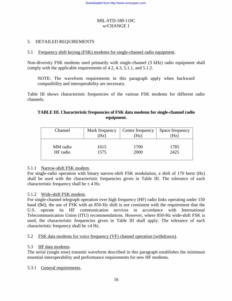
Table III shows characteristic frequencies of the various FSK modems for different radio
channels.
TABLE III. Characteristic frequencies of FSK data modems for single-channel radio
equipment.
Channel Mark frequency
(Hz)
Center frequency
(Hz)
Space frequency
(Hz)
MM radio 1615 1700 1785
HF radio 1575 2000 2425
5.1.1 Narrow-shift FSK modem.
For single-radio operation with binary narrow-shift FSK modulation, a shift of 170 hertz (Hz)
shall be used with the characteristic frequencies given in Table III. The tolerance of each
characteristic frequency shall be ± 4 Hz.
5.1.2 Wide-shift FSK modem.
For single-channel telegraph operation over high frequency (HF) radio links operating under 150
baud (Bd), the use of FSK with an 850-Hz shift is not consistent with the requirement that the
U.S. operate its HF communication services in accordance with International
Telecommunication Union (ITU) recommendations. However, where 850-Hz wide-shift FSK is
used, the characteristic frequencies given in Table III shall apply. The tolerance of each
characteristic frequency shall be ±4 Hz.
5.2 FSK data modems for voice frequency (VF) channel operation (withdrawn).
5.3 HF data modems.
The serial (single tone) transmit waveform described in this paragraph establishes the minimum
essential interoperability and performance requirements for new HF modems.
5.3.1 General requirements.
Downloaded from http://www.everyspec.com
MIL-STD-188-110C
w/CHANGE 1
17
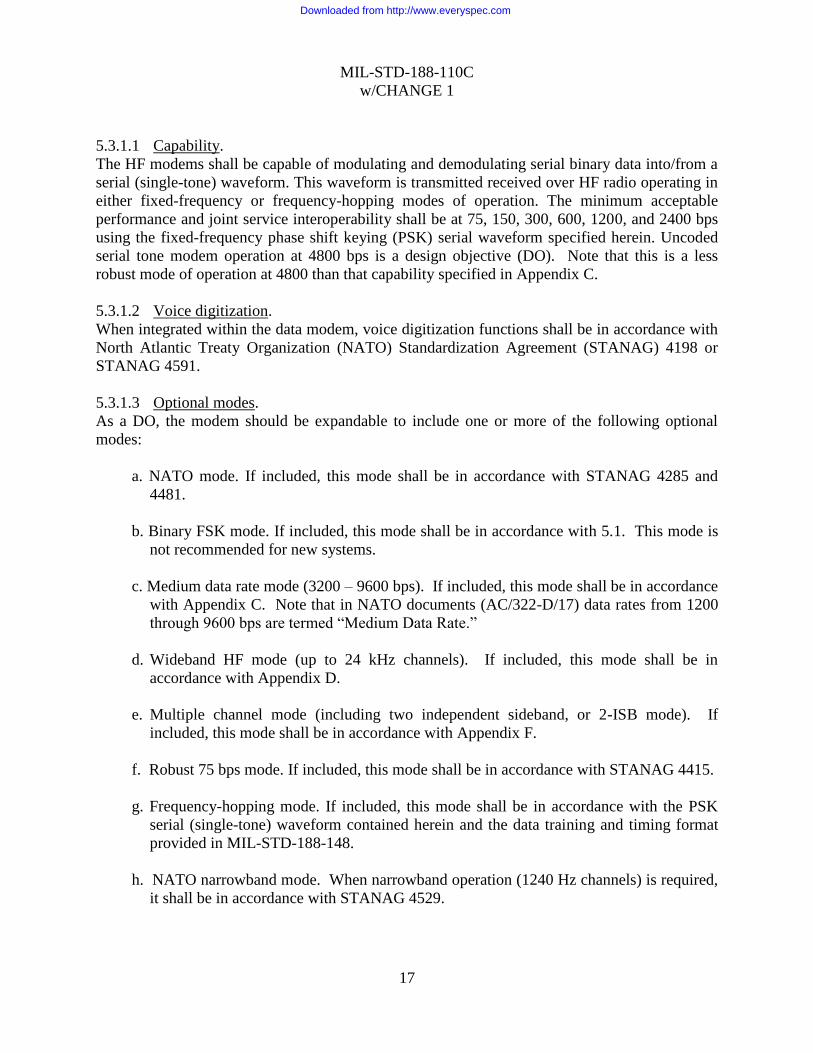
5.3.1.1 Capability.
The HF modems shall be capable of modulating and demodulating serial binary data into/from a
serial (single-tone) waveform. This waveform is transmitted received over HF radio operating in
either fixed-frequency or frequency-hopping modes of operation. The minimum acceptable
performance and joint service interoperability shall be at 75, 150, 300, 600, 1200, and 2400 bps
using the fixed-frequency phase shift keying (PSK) serial waveform specified herein. Uncoded
serial tone modem operation at 4800 bps is a design objective (DO). Note that this is a less
robust mode of operation at 4800 than that capability specified in Appendix C.
5.3.1.2 Voice digitization.
When integrated within the data modem, voice digitization functions shall be in accordance with
North Atlantic Treaty Organization (NATO) Standardization Agreement (STANAG) 4198 or
STANAG 4591.
5.3.1.3 Optional modes.
As a DO, the modem should be expandable to include one or more of the following optional
modes:
a. NATO mode. If included, this mode shall be in accordance with STANAG 4285 and
4481.
b. Binary FSK mode. If included, this mode shall be in accordance with 5.1. This mode is
not recommended for new systems.
c. Medium data rate mode (3200 – 9600 bps). If included, this mode shall be in accordance
with Appendix C. Note that in NATO documents (AC/322-D/17) data rates from 1200
through 9600 bps are termed “Medium Data Rate.”
d. Wideband HF mode (up to 24 kHz channels). If included, this mode shall be in
accordance with Appendix D.
e. Multiple channel mode (including two independent sideband, or 2-ISB mode). If
included, this mode shall be in accordance with Appendix F.
f. Robust 75 bps mode. If included, this mode shall be in accordance with STANAG 4415.
g. Frequency-hopping mode. If included, this mode shall be in accordance with the PSK
serial (single-tone) waveform contained herein and the data training and timing format
provided in MIL-STD-188-148.
h. NATO narrowband mode. When narrowband operation (1240 Hz channels) is required,
it shall be in accordance with STANAG 4529.
Downloaded from http://www.everyspec.com
MIL-STD-188-110C
w/CHANGE 1
18
5.3.1.4 Interface requirements.
5.3.1.4.1 Line-side data characteristics.
Line-side data interfaces shall be in accordance with 4.2.3.
5.3.1.4.2 LAN interface (DO).
If an additional Ethernet LAN interface is provided (see Joint Technical Architecture,
2.3.2.2.2.1: Local Area Network (LAN) Access), the modem should be capable of performing
both line side and Remote Control (see 5.3.1.5) interface functions over the LAN including
transport of user data, in accordance with Appendix A.
5.3.1.4.3 Equipment side characteristics (informative).
Modems shall be designed to provide the required performance (see 5.3.2.5) using the single-
channel bandwidth and characteristics as given in MIL-STD-188-141.
5.3.1.4.4 Transmit override.
When operating in other than full duplex mode, data presented for transmission at the line-side or
LAN interface shall cause the modem to commence transmit operation, overriding any reception
of data on the equipment side. An option may be provided to disable transmit override, so that
CTS is delayed after the assertion of RTS until a reception in progress is complete.
5.3.1.4.5 Buffering in synchronous serial mode.
When transferring line-side data in the synchronous mode, the modem shall transmit all user data
that occur after the assertion of CTS by the modem and before the de-assertion of RTS by the
DTE. At the receive end of the link, all of the bits that occur in this interval shall be delivered by
the modem to the DTE. Transmission and reception of user bits that fall outside this interval is
not precluded.
5.3.1.5 Remote control interface.
A remote control interface is mandatory for all new procurements of HF data modems.
5.3.1.5.1 Electrical interface.
The electrical interface for remote control of the modem shall comply with the specified
industrial or military interface standard.
5.3.1.5.2 Optional modem control driver.
As an option a software remote control driver shall be supplied for installation in a remote
control unit that provides an open, documented Application Programming Interface (API) to
communications software.
5.3.2 Serial (single-tone) mode.
5.3.2.1 General.
This mode shall employ M-ary phase-shift keying (PSK) on a single carrier frequency as the
modulation technique for data transmission. Serial binary information accepted at the line-side
Downloaded from http://www.everyspec.com
MIL-STD-188-110C
w/CHANGE 1
19
input is converted into a single 8-ary PSK-modulated output carrier. The modulation of this
output carrier shall be a constant 2400-symbols-per-second waveform regardless of the actual
throughput rate. The rate-selection capability shall be as given in 5.3.1.1. Selectable interleaver
settings shall be provided. This waveform (signal structure) has four functionally distinct,
sequential transmission phases. These time phases are:
a. Synchronization preamble phase.
b. Data phase.
c. End-of-message (EOM) phase.
d. Coder and interleaver flush phase.
NOTE: Unless otherwise specified, the included serial (single-tone) waveform
requirements apply to both the fixed-frequency and frequency-hopping modes of
operation.
5.3.2.2 Sequencing of time phases.
Figure 2 illustrates the functional block diagram for fixed-frequency and frequency-hopping
operation.
Downloaded from http://www.everyspec.com

MIL-STD-188-110C
w/CHANGE 1
20
EOM
SEQUENCE
FEC
ENCODER
DATA
SEQUENCE
RANDOMIZING
GENERATOR
SYNC
SEQUENCE
RANDOMIZING
GENERATOR
MODULATORSCRAMBLER
SYMBOL
FORMATION
MODIFIED
GRAY
DECODER
(MGD)
SYNC
PREAMBLE
SEQUENCE
INTERLEAVE
MATRIX #2
INTERLEAVE
MATRIX #1
OUTPUTKNOWN
DATA
(PROBE)
UNKNOWN
DATA
S4
S2
S3
S1
ZERO
(FLUSH)
UNKNOWN
DATA
SYNC
DATA SYNC
FIGURE 2. Serial (single-tone) waveform functional block diagram
Downloaded from http://www.everyspec.com

MIL-STD-188-110C
w/CHANGE 1
21
5.3.2.2.1 Synchronization (sync) preamble phase.
The duration of the sync preamble phase shall correspond to the exact time required to load the
selected interleaver matrix when an interleaver is present, with one block of data. During this
phase, switch S1 (see figure 2) shall be in the UNKNOWN DATA position and the encode and
load interleave functions shall be active as the modem begins accepting data from the data
terminal equipment (DTE). Switches S2 and S3 shall be in the SYNC position. The transmitting
modem shall send the required sync preamble sequence (see 5.3.2.3.7.2) to achieve time and
frequency sync with the receiving modem. The length of the sync preamble sequence pattern
shall be 0.6 s for the zero interleaver setting (this requires that a 0.6 s buffer be used to delay data
traffic during the sync preamble transmission), 0.6 s for the short interleaver setting, and 4.8 s for
the long interleaver setting. For radio frequency hopping operation, S4 and the data fetch
controller shall provide the required traffic dead time at the beginning of each hop by disabling
the modem output. The dead time shall be equal to the duration of 96 symbols. Switch S4 shall
be placed in the through position during fixed-frequency operation. Referring to figure 3, the
sequence of events for synchronous and asynchronous operation is as follows:
a. For fixed-frequency, full-duplex data operation, upon receipt of the message request-
to-send (RTS) signal from the DTE, the modem shall simultaneously perform the following;
(1) Return to the DTE a clear-to-send (CTS) signal,
(2) Begin loading the interleaver with data traffic, and
(3) Commence sending the special sync preamble pattern described in 5.3.2.3.7.2 and
5.3.2.3.8.2.
b. For fixed-frequency half-duplex (one-way reversible) data operation using radio
equipment without automatic link establishment (ALE) capability, the radio set transmitter shall
be keyed first, then the sequence of events shall be identical to that given for fixed-frequency
full-duplex operation.
c. Fixed-frequency half duplex data operation using ALE radio equipment shall incorporate
a method of delaying the data CTS signal until radio link confirmation. In an example of this
operation, upon receipt of the RTS signal from the user data terminal, the controller first initiates
and confirms linking with the called station. During this link confirmation period, the RTS signal
is controlled and delayed in the controller until the link is confirmed. After link confirmation, the
controller sends the RTS signal to the modem. (In effect, the delaying of the RTS signal provides
the needed delay of the data CTS signal.) Upon receipt of the RTS signal from the controller, the
modem shall simultaneously perform the following:
(1) Key the radio,
(2) Return to the DTE a CTS signal,
(3) Begin loading the interleaver with data traffic, and
(4) Commence sending the special sync pattern described in 5.3.2.3.7.2 and 5.3.2.3.8.2.
Downloaded from http://www.everyspec.com

MIL-STD-188-110C
w/CHANGE 1
22
USERDATA/
TRAFFICTERMINAL
AUTOMATICNODE
CONTROLLER
AUTOMATICNODE
CONTROLLER
HFMODEM
HFRADIO
DTE DTEDCE DCE RTE RCE RTE RCE
RTS2 RTX RTX2
PTT
CTS
TD
RD RD2
TD2
CTX
RA RS
DCD DCD
RC
TC
RC2
TC2
K
CTSCTS2
LINK
RTS RTS RTS RTX RTX
K
K
K
K
K
K
DETECT
CARRIER
DCD2 DCD
TC TC2
RC2 RC
RD RD
TDTD
CTS
TS
OR
CTX
HOPPAUSE
CTX2 CTX*** ***
TUNE&TX
K
K
K
SYNC
HF AUTOMATIC NODE
CONTROLLER (ANC)
TA TA TA2 TA
RA2 RA RA
KPTT
AND
PREP
FIGURE 3. An example of equipment interface block diagram.
Downloaded from http://www.everyspec.com
MIL-STD-188-110C
w/CHANGE 1
23
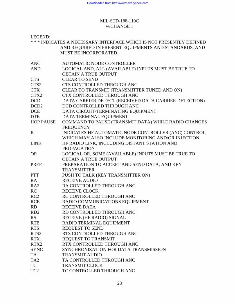
LEGEND:
* * * INDICATES A NECESSARY INTERFACE WHICH IS NOT PRESENTLY DEFINED
AND REQUIRED IN PRESENT EQUIPMENTS AND STANDARDS, AND
MUST BE INCORPORATED.
ANC AUTOMATIC NODE CONTROLLER
AND LOGICAL AND, ALL (AVAILABLE) INPUTS MUST BE TRUE TO
OBTAIN A TRUE OUTPUT
CTS CLEAR TO SEND
CTS2 CTS CONTROLLED THROUGH ANC
CTX CLEAR TO TRANSMIT (TRANSMITTER TUNED AND ON)
CTX2 CTX CONTROLLED THROUGH ANC
DCD DATA CARRIER DETECT (RECEIVED DATA CARRIER DETECTION)
DCD2 DCD CONTROLLED THROUGH ANC
DCE DATA CIRCUIT-TERMINATING EQUIPMENT
DTE DATA TERMINAL EQUIPMENT
HOP PAUSE COMMAND TO PAUSE (TRANSMIT DATA) WHILE RADIO CHANGES
FREQUENCY
K INDICATES HF AUTOMATIC NODE CONTROLLER (ANC) CONTROL,
WHICH MAY ALSO INCLUDE MONITORING AND/OR INJECTION.
LINK HF RADIO LINK, INCLUDING DISTANT STATION AND
PROPAGATION
OR LOGICAL OR, SOME (AVAILABLE) INPUTS MUST BE TRUE TO
OBTAIN A TRUE OUTPUT
PREP PREPARATION TO ACCEPT AND SEND DATA, AND KEY
TRANSMITTER
PTT PUSH TO TALK (KEY TRANSMITTER ON)
RA RECEIVE AUDIO
RA2 RA CONTROLLED THROUGH ANC
RC RECEIVE CLOCK
RC2 RC CONTROLLED THROUGH ANC
RCE RADIO COMMUNICATIONS EQUIPMENT
RD RECEIVE DATA
RD2 RD CONTROLLED THROUGH ANC
RS RECEIVE (HF RADIO) SIGNAL
RTE RADIO TERMINAL EQUIPMENT
RTS REQUEST TO SEND
RTS2 RTS CONTROLLED THROUGH ANC
RTX REQUEST TO TRANSMIT
RTX2 RTX CONTROLLED THROUGH ANC
SYNC SYNCHRONIZATION FOR DATA TRANSMISSION
TA TRANSMIT AUDIO
TA2 TA CONTROLLED THROUGH ANC
TC TRANSMIT CLOCK
TC2 TC CONTROLLED THROUGH ANC
Downloaded from http://www.everyspec.com

MIL-STD-188-110C
w/CHANGE 1
24
TD TRANSMIT DATA
TD2 TD CONTROLLED THROUGH ANC
TS TRANSMIT (HF RADIO) SIGNAL
TUNE TUNING OF THE TRANSMITTER AND ANTENNA SYSTEM BEFORE
TRANSMIT
TX TRANSMIT (HF RADIO ON AND READY TO SEND DATA)
FIGURE 3. An example of equipment interface block diagram - Continued.
d. For frequency-hopping data operation, the modem shall, upon receipt of the RTS signal
from the DTE input device, simultaneously perform the following:
(1) key the radio,
(2) return a data CTS signal to the DTE,
(3) commence loading the interleaver, and
(4) wait for the radio clear-to-transmit (CTX) signal. In no case shall the radio CTX
signal occur later than 2.4 seconds after receipt of the data CTS signal. This
requires, in addition to an interleaver buffer, a buffer of at least 2.45 times the
highest data rate used.
NOTE: This additional buffer shall be bypassed during fixed-frequency operation.
Upon receipt of the radio CTX, the transmitting modem shall then commence sending the sync
pattern as given in 5.3.2.3.7.2 and 5.3.2.3.8.2, and will use the data framing and timing format
in MIL-STD-188-148.
NOTE: The interleaver fetch and modified Gray decoding functions are not active
during this phase. All received data prior to entry into the data phase must be
buffered by the modem. The radio CTX signal can originate from either the radio
set itself or, if using ALE radio equipment, an ALE controller.
5.3.2.2.2 Data phase.
During the data phase, the transmit waveform shall contain both message information
(UNKNOWN DATA) and channel probes (KNOWN DATA), that is, training bits reserved for
channel equalization by the distant receive modem. Function switches S1 and S3 (figure 2) are
in the UNKNOWN DATA and DATA position, respectively, and switch S2 toggles between
the UNKNOWN DATA (modified Gray decoder (MGD) output) and the KNOWN DATA
(probe) positions. The probe shall consist of zeros, D1, and D2 (D1 and D2 are defined in
5.3.2.3.7.1.2). The period of dwell in each switch position shall be as follows:
Downloaded from http://www.everyspec.com

MIL-STD-188-110C
w/CHANGE 1
25
a. For frequency-hopping operation, the dwell is a function of bit rate and time duration of
the hop. MIL-STD-188-148 gives the required timing of switches S2 and S4 during each
hop time as a function of data rate and dead time.
b. For fixed-frequency operation, the period of dwell shall be a function of bit rate only.
At 2400 and 4800 bps, there shall be a 32-symbol duration in the UNKNOWN DATA
position followed by a 16-symbol duration in the KNOWN DATA position. At 150, 300,
600, and 1200 bps, the two durations shall be 20 symbols in each position. At 75 bps,
switch S2 shall remain in the UNKNOWN DATA position. Data transfer operation shall
be terminated by removal of the RTS signal by the input DTE.
NOTE: In all cases, switch S2 is placed in the UNKNOWN DATA position first,
following the end of the sync preamble phase.
5.3.2.2.3 EOM phase.
When the last UNKNOWN DATA bit prior to the absence of the RTS signal has entered the
forward error correction (FEC) encoder, S1 (figure 2) shall be switched to the EOM position.
This shall cause a fixed 32-bit pattern (see 5.3.2.3.1) to be sent to the FEC encoder. Function
switches S2 and S3 (and also S4 in frequency-hopping operation) shall continue to operate as
established for the data phase.
5.3.2.2.4 FEC coder and interleaver flush phase.
Immediately upon completion of the EOM phase, S1 (figure 2 shall be switched to the FLUSH
position causing input of flush bits (see 5.3.2.3.2) to the FEC encoder.
5.3.2.3 Functional descriptions.
The following subparagraphs provide figure 2 block descriptions.
5.3.2.3.1 EOM sequence.
The eight-digit hexadecimal number, 4B65A5B2 shall represent the EOM sequence. The bits
shall be transmitted with the most significant digit first. Thus the first eight bits are, left to
right, 0100 1011.
5.3.2.3.2 Interleaver flush
If an interleaver is used, the duration of the flush phase shall be 144 bits (for coder flush) plus
enough bits to complete transmission of the remainder of the interleaved matrix data block (see
5.3.2.3.4 for data block size) containing the last coder flush bit. Flush bits shall be set to "0". If
the interleaver is in a bypass (0.0 s) state, only the coder flush bits are transmitted.
NOTE: This causes the transmission of enough flush bits to allow effective flushing
of the FEC decoder and the deinterleaver at the receiving modem.
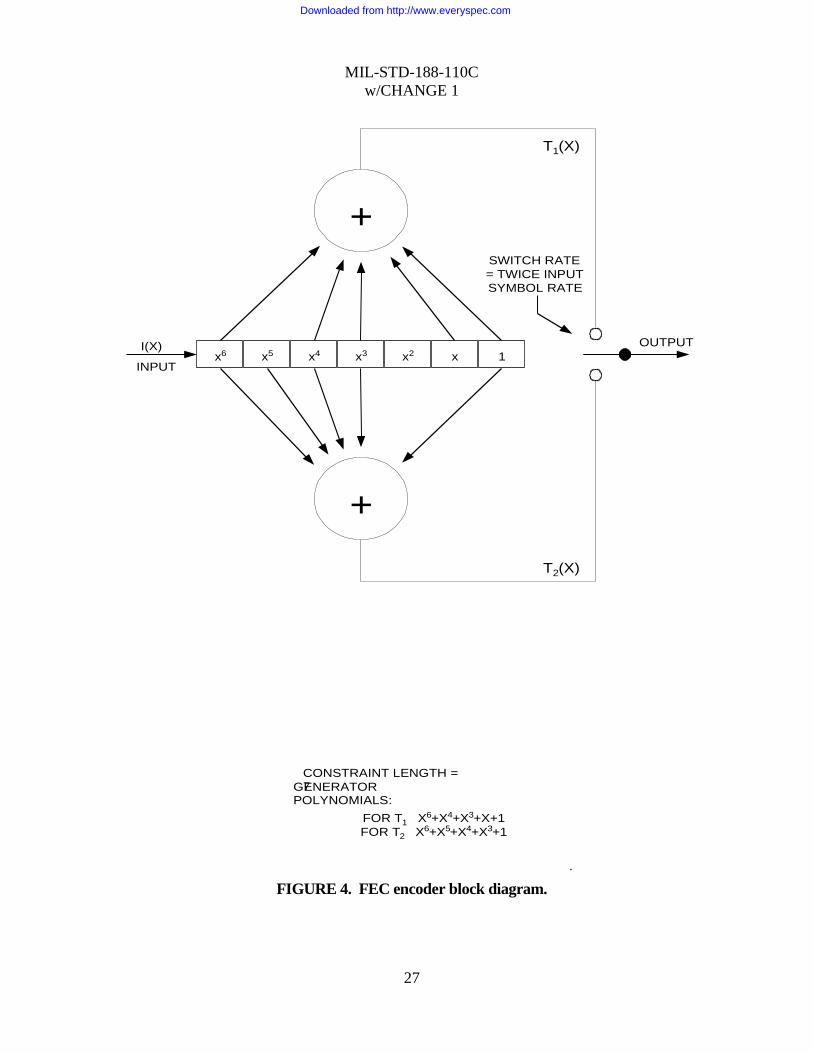
5.3.2.3.3 FEC encoder.
The FEC encoder shall be used for data rates up to and including 2400 bps. The FEC encoder
block diagram for frequency-hopping and fixed-frequency operation is shown on figure 4.
Downloaded from http://www.everyspec.com

MIL-STD-188-110C
w/CHANGE 1
26
a. For frequency-hopping operation, the FEC encoder function shall be accomplished by
a constraint length 7 convolutional coder with repeat coding used at the 75, 150, and 300 bps
rates. The two summing nodes on the figure represent modulo 2 addition. For each bit input to
the encoder, two bits shall be taken as output from the encoder, the upper output bit Tl(x) being
taken first. For the 2400 bps rate, every fourth bit (the second value of T2(x) shall be omitted at
the interleaver output to form a punctured rate 2/3 convolutional rate. At all other rates, the
convolutional coder shall be rate 1/2. Coded bit streams of 3600, 2400, and 1200 bps shall be
generated for the input data rates of 2400, 1200, and 600 bps, respectively. For the 300, 150,
and 75 bps input data rates, a 1200 bps coded bit stream shall be generated by repeating the
pairs of output bits the appropriate number of times. The bits shall be repeated in pairs rather
than repetitions for the first, Tl(x), followed by repetitions of the second T2(x). Error correction
coding for frequency-hopping operation shall be in accordance with Table IV.
TABLE IV. Error correcting coding, frequency hopping operation.
Data
rate (bps)
Effective
Code rate
Method for achieving the code rate
2400 2/3 Rate 2/3 punctured convolutional code
1200 1/2 Rate 1/2 code
600 1/2 Rate l/2 code
300 1/4 Rate l/2 code repeated 2 times
150 1/8 Rate 1/2 code repeated 4 times
75 1/16 Rate 1/2 code repeated 8 times
Downloaded from http://www.everyspec.com
MIL-STD-188-110C
w/CHANGE 1
27
x6 1xx2x3x4x5
+
+
OUTPUT
SWITCH RATE
= TWICE INPUT
SYMBOL RATE
T1(X)
T2(X)
I(X)
INPUT
CONSTRAINT LENGTH =7GENERATOR
POLYNOMIALS:
FOR T1 X6+X4+X3+X+1
FOR T2 X6+X5+X4+X3+1
.
FIGURE 4. FEC encoder block diagram.
Downloaded from http://www.everyspec.com

MIL-STD-188-110C
w/CHANGE 1
28
b. For fixed-frequency operation, the FEC encoder function shall be accomplished by a
single rate 1/2 constraint length 7 convolutional coder with repeat coding used at 150 and 300
bps. The two summing nodes shall operate as given for frequency-hopping operation; that is,
for each bit input to the encoder, two bits shall be taken as output from the encoder. Coded bit
streams of 4800, 2400, and 1200 bps shall be generated for input data rates of 2400, 1200, and
600 bps, respectively. For 300-bps and 150-bps input data rates, repeating the pairs of output
bits the appropriate number of times shall generate a 1200-bps coded bit stream. The bits shall
be repeated in pairs rather than repetitions for the first, T1(X), followed by repetitions of the
second T2(X). At 75 bps, a different transmit format (see 5.3.2.3.7.1.1) is used and the effective
code rate of 1/2 shall be employed to produce a 150-bps coded stream. Error correction coding
for fixed-frequency operation shall be in accordance with Table V.
TABLE V. Error-correcting coding, fixed frequency operation.
Data
rate (bps)
Effective
code rate
Method for achieving the code rate
4800 (no coding) (no coding)
2400 1/2 Rate 1/2
1200 1/2 Rate 1/2 code
600 1/2 Rate1/2 code
300 1/4 Rate l/2 code repeated 2 times
150 1/8 Rate 1/2 code repeated 4 times
75 1/2 Rate 1/2
c. For 4800-bps fixed-frequency operation, the FEC encoder shall be bypassed.
5.3.2.3.4 Interleave load.
The interleaver, when used, shall be a matrix block type that operates upon input bits. The
matrix size shall accommodate block storage of 0.0, 0.6, or 4.8 s of receiving bits (depending
on whether the zero, short, or long interleave setting is chosen) at all required data rates.
Because the bits are loaded and fetched in different orders, two distinct interleave matrices
shall be required.
NOTE: This allows one block of data to be loaded while the other is being fetched.
The selection between the long and short interleaves is contained in the transmitted
sync pattern (5.3.2.3.7.2). The short interleaves shall be switch selectable to be
either 0.0 s or 0.6 s (see 5.3.2.3.7.2.1).
To maintain the interleave delay at a constant value, the block size shall be scaled by bit rate.
Table VI lists the interleaver matrix dimensions (rows and columns) that shall be allocated for
each required bit rate and interleave delay.
NOTE: For frequency-hopping operation at rates of 300, 150, and 75 bps, the
number of bits required for a constant time delay is the same as that for 600 bps due
Downloaded from http://www.everyspec.com
MIL-STD-188-110C
w/CHANGE 1
29
to repeat coding. For fixed-frequency operation, repeat coding is used with only the
300-bps and 150-bps rates.
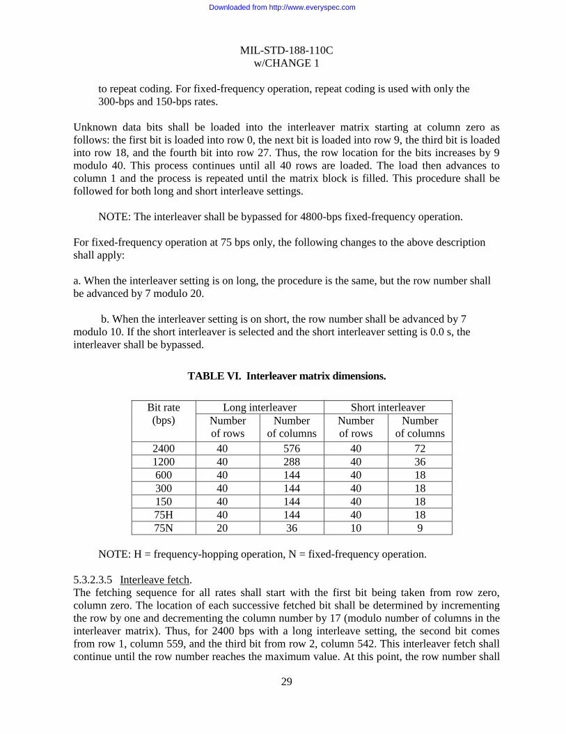
Unknown data bits shall be loaded into the interleaver matrix starting at column zero as
follows: the first bit is loaded into row 0, the next bit is loaded into row 9, the third bit is loaded
into row 18, and the fourth bit into row 27. Thus, the row location for the bits increases by 9
modulo 40. This process continues until all 40 rows are loaded. The load then advances to
column 1 and the process is repeated until the matrix block is filled. This procedure shall be
followed for both long and short interleave settings.
NOTE: The interleaver shall be bypassed for 4800-bps fixed-frequency operation.
For fixed-frequency operation at 75 bps only, the following changes to the above description
shall apply:
a. When the interleaver setting is on long, the procedure is the same, but the row number shall
be advanced by 7 modulo 20.
b. When the interleaver setting is on short, the row number shall be advanced by 7
modulo 10. If the short interleaver is selected and the short interleaver setting is 0.0 s, the
interleaver shall be bypassed.
TABLE VI. Interleaver matrix dimensions.
Bit rate
(bps)
Long interleaver Short interleaver
Number
of rows
Number
of columns
Number
of rows
Number
of columns
2400 40 576 40 72
1200 40 288 40 36
600 40 144 40 18
300 40 144 40 18
150 40 144 40 18
75H 40 144 40 18
75N 20 36 10 9
NOTE: H = frequency-hopping operation, N = fixed-frequency operation.
5.3.2.3.5 Interleave fetch.
The fetching sequence for all rates shall start with the first bit being taken from row zero,
column zero. The location of each successive fetched bit shall be determined by incrementing
the row by one and decrementing the column number by 17 (modulo number of columns in the
interleaver matrix). Thus, for 2400 bps with a long interleave setting, the second bit comes
from row 1, column 559, and the third bit from row 2, column 542. This interleaver fetch shall
continue until the row number reaches the maximum value. At this point, the row number shall
Downloaded from http://www.everyspec.com

MIL-STD-188-110C
w/CHANGE 1
30
be reset to zero, the column number is reset to be one larger than the value it had when the row
number was last zero and the process continued until the entire matrix data block is unloaded.
The interleaver fetch process shall be the same for frequency-hopping and fixed-frequency
operation except as follows:
a. For frequency-hopping operation (as stated in 5.3.2.3.3), the puncture process at 2400 bps
shall occur during the fetch routine by omitting every fourth bit from the interleaver output.
b. For fixed-frequency operation at the 75-bps rate, the interleaver fetch is similar except
the decrement value of the column number shall be 7 rather than 17.
The bits obtained from the interleaver matrix shall be grouped together as one, two, or three bit
entities that will be referred to as channel symbols. The number of bits that must be fetched per
channel symbol shall be a function of bit rate as given in Table VII.
TABLE VII. Bits-per-channel symbol.
Data rate (bps) Number of bits fetched per
channel symbol
2400 3
1200 2
600 1
300 1
150 1
75H 1
75N 2
NOTE: H = frequency-hopping operation, N = fixed-frequency operation.
5.3.2.3.6 Modified-Gray decoder.
At 4800 and 2400 bps, the channel bits are effectively transmitted with 8-ary channel symbols.
At 1200 bps and 75 bps (fixed frequency), the channel bits are effectively transmitted with
4-ary channel symbols.
NOTE: The purpose of decoding the bits from the interleaver matrix (through the
MGD) is to guarantee that only one bit is in error when symbol errors involving
adjacent phases are made at the receiving demodulator.
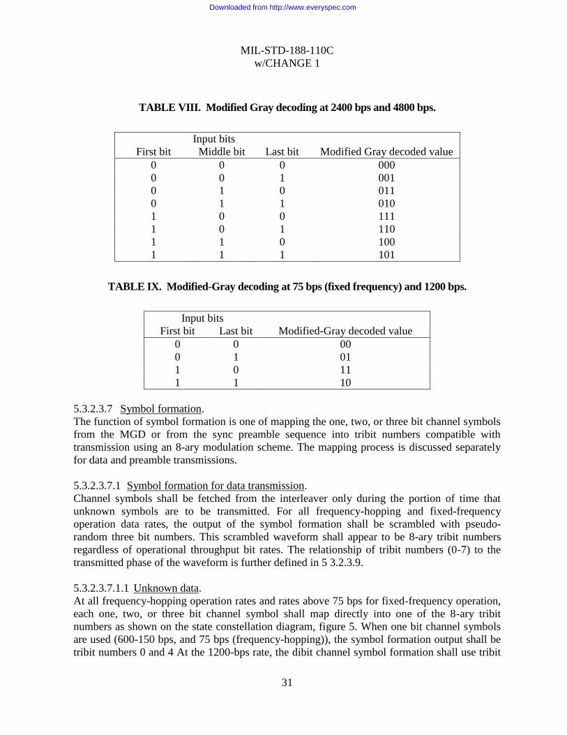
Modified Gray decoding of the 2400 bps, 4800 bps (tribit), and 75 bps (fixed frequency) 1200
bps (dibit) channel symbols shall be in accordance with Tables VIII and IX respectively. When
one-bit channel symbols are used (600-150 bps, and 75 bps (frequency-hopping operation)) the
MGD does not modify the unknown data bit stream.
Downloaded from http://www.everyspec.com
MIL-STD-188-110C
w/CHANGE 1
31
TABLE VIII. Modified Gray decoding at 2400 bps and 4800 bps.
Input bits
First bit Middle bit Last bit Modified Gray decoded value
0 0 0 000
0 0 1 001
0 1 0 011
0 1 1 010
1 0 0 111
1 0 1 110
1 1 0 100
1 1 1 101
TABLE IX. Modified-Gray decoding at 75 bps (fixed frequency) and 1200 bps.
Input bits
First bit Last bit Modified-Gray decoded value
0 0 00
0 1 01
1 0 11
1 1 10
5.3.2.3.7 Symbol formation.
The function of symbol formation is one of mapping the one, two, or three bit channel symbols
from the MGD or from the sync preamble sequence into tribit numbers compatible with
transmission using an 8-ary modulation scheme. The mapping process is discussed separately
for data and preamble transmissions.
5.3.2.3.7.1 Symbol formation for data transmission.
Channel symbols shall be fetched from the interleaver only during the portion of time that
unknown symbols are to be transmitted. For all frequency-hopping and fixed-frequency
operation data rates, the output of the symbol formation shall be scrambled with pseudo-
random three bit numbers. This scrambled waveform shall appear to be 8-ary tribit numbers
regardless of operational throughput bit rates. The relationship of tribit numbers (0-7) to the
transmitted phase of the waveform is further defined in 5 3.2.3.9.
5.3.2.3.7.1.1 Unknown data.
At all frequency-hopping operation rates and rates above 75 bps for fixed-frequency operation,
each one, two, or three bit channel symbol shall map directly into one of the 8-ary tribit
numbers as shown on the state constellation diagram, figure 5. When one bit channel symbols
are used (600-150 bps, and 75 bps (frequency-hopping)), the symbol formation output shall be
tribit numbers 0 and 4 At the 1200-bps rate, the dibit channel symbol formation shall use tribit
Downloaded from http://www.everyspec.com
MIL-STD-188-110C
w/CHANGE 1
32
numbers 0, 2, 4, and 6. At the 4800-bps and 2400-bps rates, all the tribit numbers (0-7) shall be
used for symbol formation. At 75 bps fixed-frequency operation, the channel symbols shall
consist of two bits for 4-ary channel symbol mapping. Unlike the higher rates, no known
symbols (channel probes) shall be transmitted and no repeat coding shall be used. Instead, the
use of 32 tribit numbers shall be used to represent each of the 4-ary channel symbols. The
mapping that shall be used is given in Table X. The mapping in Table Xa shall be used for all
sets of 32 tribit numbers with the exception of every 45th set (following the end of the sync
pattern) if short interleave is selected, and every 360th set (following the end of sync pattern) if
long interleave is selected. These exceptional sets, every 45th set for short interleave and every
360th set for long interleave, shall use the mappings of Table Xb. In any case, the resultant
output is one of four orthogonal waveforms produced for each of the possible dibits of
information. As before, these values will be scrambled later to take on all 8-phase states.
NOTE: Each set consists of 32 tribit numbers. The receive modem shall use the
modification of the known data at interleaver boundaries to synchronize without a
preamble and determine the correct date rate and mode of operation.
5.3.2.3.7.1.2 Known data.
During the periods where known (channel probe) symbols are to be transmitted, the channel
symbol formation output shall be set to 0 (000) except for the two known symbol patterns
preceding the transmission of each new interleaved block.. The block length shall be 1440 tribit
channel symbols for short interleave setting and 11520 tribit channels symbols for the long
interleave setting. When the two known symbol patterns preceding the transmission of each
new interleaver block are transmitted, the 16 tribit symbols of these two known symbol patterns
shall be set to Dl and D2, respectively, as defined in Table XI of 5.3.2.3.7.2.1 and Table XIII of
5.3.2.3.7.2.2. The two known symbol patterns are repeated twice rather than four times as they
are in Table XIII to produce a pattern of 16 tribit numbers. In cases where the duration of the
known symbol pattern is 20 tribit symbols, the unused last four tribit symbols shall be set to 0
(000).
NOTE: When zero interleaver setting is selected, the pattern associated with the 0.6
s block is used. When 4800 bps operation is selected, the pattern associated with the
short interleaver setting is selected.
Downloaded from http://www.everyspec.com

MIL-STD-188-110C
w/CHANGE 1
33
TABLE X. Channel symbol mapping for 75 bps.
Channel symbol Tribit numbers
a. Mapping for normal sets
00 (0000) repeated 8 times
01 (0404) repeated 8 times
10 (0044) repeated 8 times
11 (0440) repeated 8 times
b. Mapping for exceptional sets.
00 (0000 4444) repeated 4 times
01 (0404 4040) repeated 4 times
10 (0044 4400) repeated 4 times
11 (0440 4004) repeated 4 times
5.3.2.3.7.2 Sync preamble sequence.
5.3.2.3.7.2.1 General.
The waveform for synchronization is essentially the same for all data rates. The
synchronization pattern shall consist of either three or twenty four 200 millisecond (ms)
segments (depending on whether either zero, short, or long interleave periods are used). Each
200-ms segment shall consist of a transmission of 15 three bit channel symbols as described in
5.3.2.3.7.2.2. The sequence of channel symbols shall be 0, 1, 3, 0, 1, 3, 1, 2, 0. Dl, D2, C1, C2,
C3, 0.
The three bit values of Dl and D2 shall designate the bit rate and interleave setting of the
transmitting modem. Table XI gives the assignment of these values.
NOTE: The D1, D2 combinations 5,6 and 5,7 are reserved for application-specific
use.
If a demodulator receives any D1, D2 combination that it does not implement, it shall not
synchronize but shall continue to search for synchronization.
NOTE: The short interleave can be selected to either 0.0 (bypassed) or 0.6 s. The
short interleave generally should be set to 0.6 s. If the 0.0s interleave is selected,
coordination with the distant terminal must be made before transmitting data. An
automatic feature of selection between the 0.0 s and 0.6 s interleaver for both
transmitter and receiver is a DO.
The three count symbols C1, C2, and C3 shall represent a count of the 200 ms segments
starting at 2 for the zero and short sync (interleave) setting cases and 23 for the long sync
(interleave) case. The count in either case shall start at the value established by the sync case
Downloaded from http://www.everyspec.com

MIL-STD-188-110C
w/CHANGE 1
34
setting and count down each segment to zero. The values shall be read as a six-bit word (C1,
C2, C3), where C1 contains the most significant two bits. The two bit values of each C (C1, C2,
C3) shall be converted to three bit values. Adding a “1” before the two-bit value does this so
that this "1" becomes the most significant bit. This conversion shall be as shown in Table XII.
NOTE: The converted count of 23 (010111) would have values of 5, 5, and 7 for C1, C2,
and C3, respectively.
TABLE XI. Assignment of designation symbols D1 and D2.
Short interleave Long interleave
Bit rate D1 D2 D1 D2
4800 7 6 reserved reserved
2400 (Digital voice). 7 7 reserved reserved
2400 (Data) 6 4 4 4
1200 6 5 4 5
600 6 6 4 6
300 6 7 4 7
150 7 4 5 4
75 7 5 5 5
TABLE XII. Conversion of two bit count value to three bit symbol.
Two-bit count value Three-bit sync symbol
00 4 (100)
10 5 (101)
01 6 (110)
11 7 (111)
Downloaded from http://www.everyspec.com
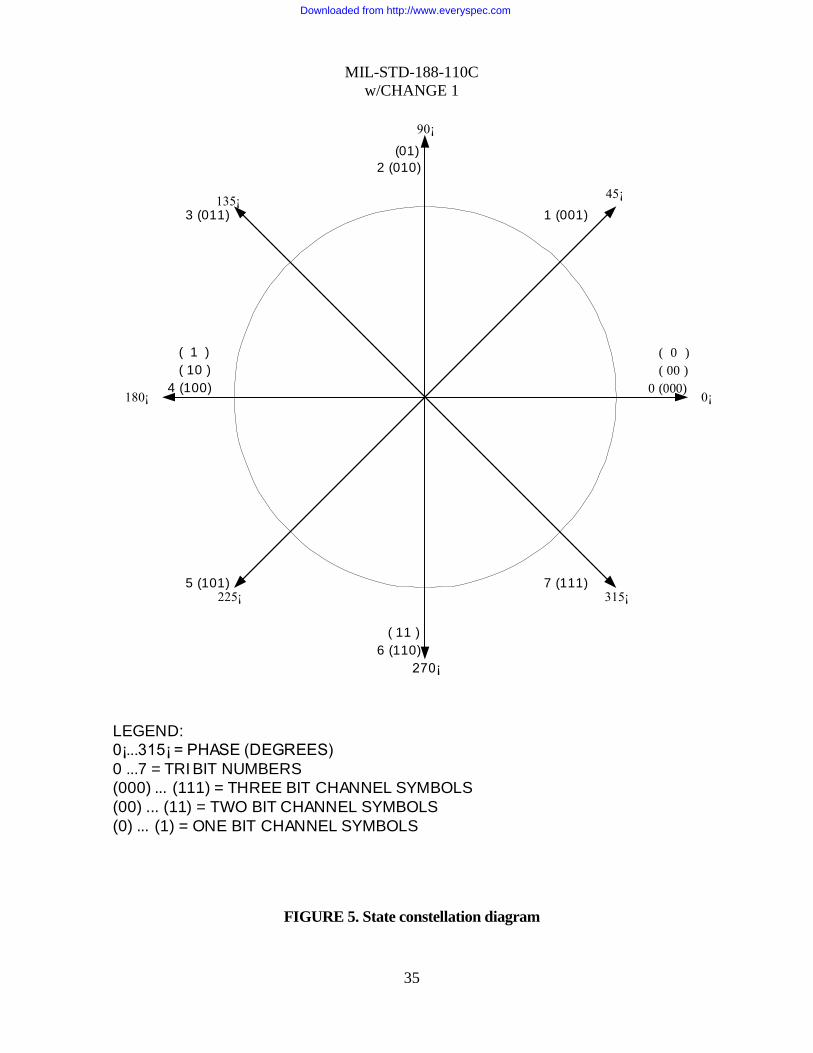
MIL-STD-188-110C
w/CHANGE 1
35
90¡
45¡
315¡
270¡
225¡
180¡
135¡
0 (000)
( 00 )
( 0 )
1 (001)
(01)
2 (010)
3 (011)
4 (100)
( 10 )
( 1 )
5 (101)
( 11 )
6 (110)
7 (111)
0¡
LEGEND:
0¡...315¡ = PHASE (DEGREES)
0 ...7 = TRI BIT NUMBERS
(000) ... (111) = THREE BIT CHANNEL SYMBOLS
(00) ... (11) = TWO BIT CHANNEL SYMBOLS
(0) ... (1) = ONE BIT CHANNEL SYMBOLS
FIGURE 5. State constellation diagram
Downloaded from http://www.everyspec.com

MIL-STD-188-110C
w/CHANGE 1
36
5.3.2.3.7.2.2 Preamble pattern generation.
The sync preamble pattern shall be a sequence of channel symbols containing three bits each
(see 5.3.2.3.7.2.1). These channel symbols shall be mapped into thirty two tribit numbers as
given in Table XIII.
NOTE: When the two known symbol patterns preceding the transmission of each
new interleaves block are transmitted, the patterns in Table XIII are repeated twice
rather than four times to produce 8 pattern of 16 tribit numbers.
TABLE XIII. Channel symbol mapping for sync preamble.
Channel Symbol Tribit Numbers
000 (0000 0000)repeated 4 times
001 (0404 0404) repeated 4 times
010 (0044 0044) repeated 4 times
011 (0440 0440) repeated 4 times
100 (0000 4444) repeated 4 times
101 (0404 4040) repeated 4 times
110 (0044 4400) repeated 4 times
111 (0440 4004) repeated 4 times
5.3.2.3.8 Scrambler.
The tribit number supplied from the symbol formation function for each 8-ary transmitted
symbol shall be modulo 8 added to a three bit value supplied by either the data sequence
randomizing generator or the sync sequence randomizing generator.
5.3.2.3.8.1 Data sequence randomizing generator.
The data sequence randomizing generator shall be a 12 bit shift register with the functional
configuration shown on figure 6. At the start of the data phase, the shift register shall be loaded
with the initial pattern shown in figure 6 (101110101101 (binary) or BAD (hexadecimal)) and
advanced eight times. The resulting three bits, as shown, shall be used to supply the scrambler
with a number from 0 to 7. The shift register shall be shifted eight times each time a new three
bit number is required (every transmit symbol period). After 160 transmit symbols, the shift
register shall be reset to BAD (hexadecimal) prior to the eight shifts.
NOTE: This sequence produces a periodic pattern 160 transmit symbols in length.
Downloaded from http://www.everyspec.com

MIL-STD-188-110C
w/CHANGE 1
37
1 10110101110
LSBMiddle
BitMSB
NOTES:
1. Initial settings shown2. Shifted 8 times between
outputs
.
FIGURE 6. Randomizing shift register functional diagram
5.3.2.3.8.2 Sync sequence randomizing Generator.
The following scrambling sequence for the sync preamble shall repeat every 32 transmitted
symbols:
7 4 3 0 5 1 5 0 2 2 1 1 5 7 4 3 5 0 2 6 2 1 6 2 0 0 5 0 5 2 6 6
where 7 shall always be used first and 6 shall be used last. The sequences in 5.3.2.3.8.1 and this
paragraph shall be modulo 8 added to the output of the symbol formation function.
5.3.2.3.9 PSK modulation.
a. The eight-phase modulation process shall be achieved by assigning the tribit numbers from
the scrambler to 45-degree increments of an 1800-Hz sinewave. Thus, 0 (000) corresponds to 0
degrees, 1 (001) corresponds to 45 degrees, 2 (010) corresponds to 90 degrees, etc. Figure 5
shows the assignment and pattern of output waveform generation.
NOTE: Since the transmit channel symbol duration is less than one cycle of the
1800-Hz carrier, the waveforms controlling the sine and cosine components must be
filtered to prevent severe aliasing.
b. Clock accuracy for generation of the 1800-Hz carrier shall be within ±1 Hz.
Downloaded from http://www.everyspec.com

MIL-STD-188-110C
w/CHANGE 1
38
5.3.2.4 Waveform summary.
For frequency-hopping and fixed-frequency operation, tables XIV and XV summarize the data
phase characteristics of the transmitted formats that shall be used for each bit rate.
NOTE: 4800 bps is not applicable to the frequency-hopping operation.
TABLE XIV. Frequency-hopping operation waveform characteristics.
Information
rate
Coding
rate
Channel
rate
Bits/channel
symbol
8-Phase
channel
symbol
Hop
format
2400 2/3 3600 3 1 *
1200 1/2 2400 2 1 *
600 1/2 1200 1 1 *
300 1/4 1200 1 1 *
150 1/8 1200 1 1 *
75 1/16 1200 1 1 *
*See MIL-STD-188-148 (S).
TABLE XV. Fixed-frequency operation waveform characteristics.
Information
rate
Coding
rate
Channel
rate
Bits/channel
symbol
8-Phase
symbols/
channel
symbol
No. of
unknown
8-phase
symbols
No. of
known 8-
phase
symbols
4800 No coding 4800 3 1 32 16
2400 1/2 4800 3 1 32 16
1200 1/2 2400 2 1 20 20
600 1/2 1200 1 1 20 20
300 1/4 1200 1 1 20 20
150 1/8 1200 1 1 20 20
75 1/2 150 2 32 All 0
5.3.2.5 Performance requirements.
The measured performance of the serial (single-tone) mode, using fixed-frequency operation
and employing the maximum interleaving period, shall be equal to or better than the coded
BER performance in Table XVI. Performance verification shall be tested using a baseband HF
simulator patterned after the Watterson Model in accordance with Appendix E. The modeled
multipath spread values and fading (two sigma) bandwidth (BW) values in Table XVI shall
consist of two independent but equal average power Rayleigh paths. For frequency-hopping
operation, an additional 2 dB in signal-to-noise ratio (SNR) shall be allowed.
Downloaded from http://www.everyspec.com
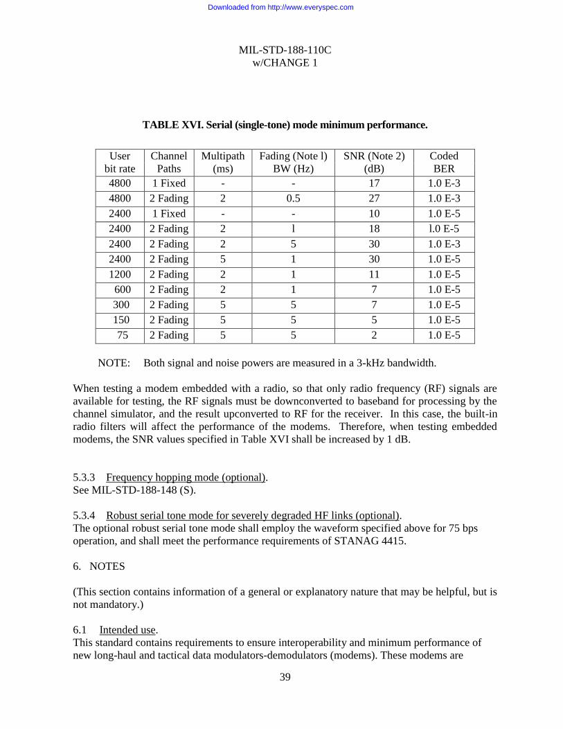
MIL-STD-188-110C
w/CHANGE 1
39
TABLE XVI. Serial (single-tone) mode minimum performance.
User
bit rate
Channel
Paths
Multipath
(ms)
Fading (Note l)
BW (Hz)
SNR (Note 2)
(dB)
Coded
BER
4800 1 Fixed - - 17 1.0 E-3
4800 2 Fading 2 0.5 27 1.0 E-3
2400 1 Fixed - - 10 1.0 E-5
2400 2 Fading 2 l 18 l.0 E-5
2400 2 Fading 2 5 30 1.0 E-3
2400 2 Fading 5 1 30 1.0 E-5
1200 2 Fading 2 1 11 1.0 E-5
600 2 Fading 2 1 7 1.0 E-5
300 2 Fading 5 5 7 1.0 E-5
150 2 Fading 5 5 5 1.0 E-5
75 2 Fading 5 5 2 1.0 E-5
NOTE: Both signal and noise powers are measured in a 3-kHz bandwidth.
When testing a modem embedded with a radio, so that only radio frequency (RF) signals are
available for testing, the RF signals must be downconverted to baseband for processing by the
channel simulator, and the result upconverted to RF for the receiver. In this case, the built-in
radio filters will affect the performance of the modems. Therefore, when testing embedded
modems, the SNR values specified in Table XVI shall be increased by 1 dB.
5.3.3 Frequency hopping mode (optional).
See MIL-STD-188-148 (S).
5.3.4 Robust serial tone mode for severely degraded HF links (optional).
The optional robust serial tone mode shall employ the waveform specified above for 75 bps
operation, and shall meet the performance requirements of STANAG 4415.
6. NOTES
(This section contains information of a general or explanatory nature that may be helpful, but is
not mandatory.)
6.1 Intended use.
This standard contains requirements to ensure interoperability and minimum performance of
new long-haul and tactical data modulators-demodulators (modems). These modems are
Downloaded from http://www.everyspec.com

MIL-STD-188-110C
w/CHANGE 1
40
intended for use in dedicated point-to-point circuits, public switched network (PSN) circuits,
and in single purpose systems such as medium frequency (MF) and high frequency (HF) radio;
however, other radio systems employ this standard.
6.2 Acquisition requirements.
Acquisition documents should specify the title, number, and date of this standard.
6.3 Subject term (key word) listing.
Asynchronous
DPSK
Error-correcting code
Fallback Operation
Fixed-frequency
Frequency hopping
FSK
Full-duplex
Modified gray decoder
Half-duplex
HF data modems
In-band signaling
Interleaving
Modulator/demodulator
PSK
QAM
Quasi-analog signals
Randomizing generator
Scrambler
Serial (single tone)
Synchronous
16-tone DPSK mode
39-tone parallel mode
6.4 Changes notations.
The margins of this standard are marked with vertical lines to indicate the modifications
generated by this change. This was done as a convenience only and the Government assumes
no liability whatsoever for any inaccuracies in these notations. Bidders and contractors are
cautioned to evaluate the requirements of this document based on the entire content irrespective
of the marginal notations.
Downloaded from http://www.everyspec.com
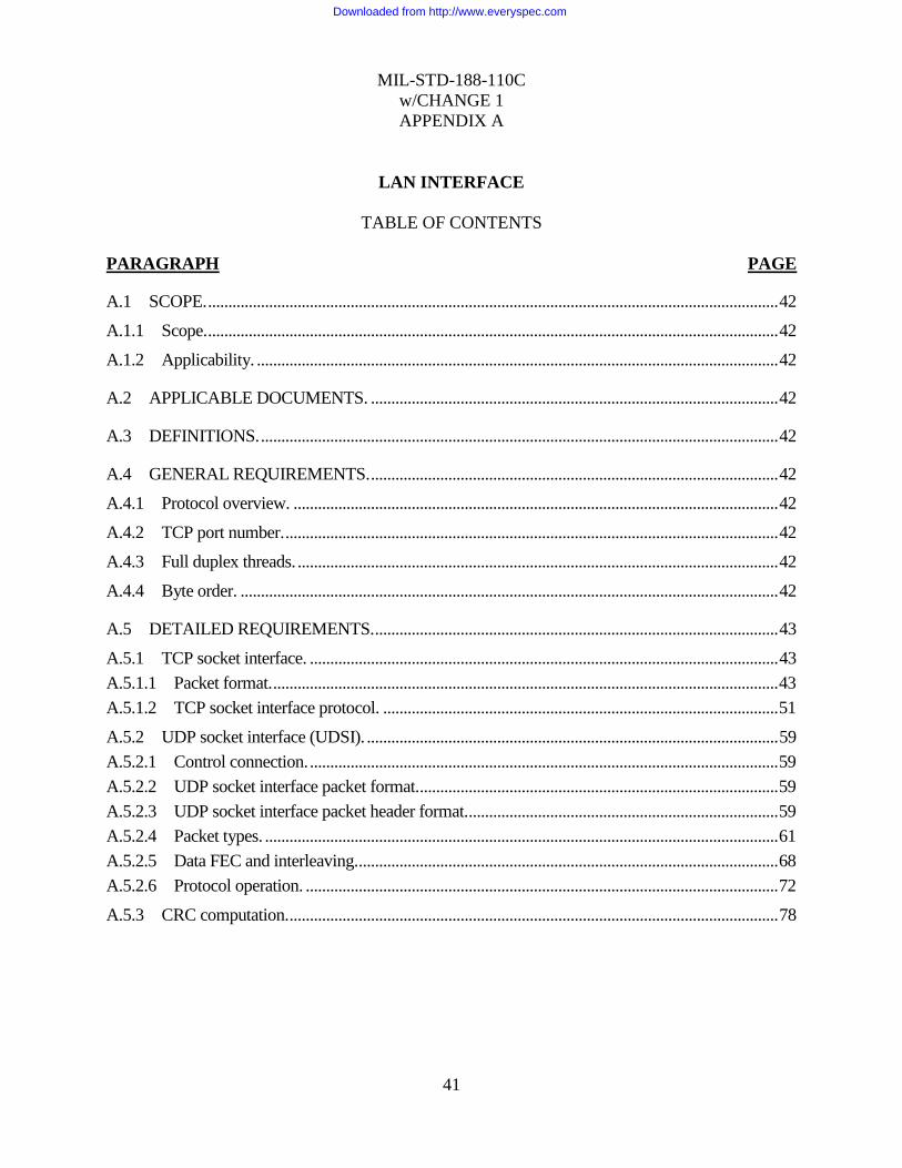
MIL-STD-188-110C
w/CHANGE 1
APPENDIX A
41
LAN INTERFACE
TABLE OF CONTENTS
PARAGRAPH PAGE
A.1 SCOPE. ............................................................................................................................................ 42
A.1.1 Scope. ............................................................................................................................................ 42
A.1.2 Applicability. ................................................................................................................................ 42
A.2 APPLICABLE DOCUMENTS. .................................................................................................... 42
A.3 DEFINITIONS. ............................................................................................................................... 42
A.4 GENERAL REQUIREMENTS. .................................................................................................... 42
A.4.1 Protocol overview. ....................................................................................................................... 42
A.4.2 TCP port number. ......................................................................................................................... 42
A.4.3 Full duplex threads. ...................................................................................................................... 42
A.4.4 Byte order. .................................................................................................................................... 42
A.5 DETAILED REQUIREMENTS. ................................................................................................... 43
A.5.1 TCP socket interface. ................................................................................................................... 43
A.5.1.1 Packet format. ............................................................................................................................ 43
A.5.1.2 TCP socket interface protocol. ................................................................................................. 51
A.5.2 UDP socket interface (UDSI). ..................................................................................................... 59
A.5.2.1 Control connection. ................................................................................................................... 59
A.5.2.2 UDP socket interface packet format. ........................................................................................ 59
A.5.2.3 UDP socket interface packet header format. ............................................................................ 59
A.5.2.4 Packet types. .............................................................................................................................. 61
A.5.2.5 Data FEC and interleaving. ....................................................................................................... 68
A.5.2.6 Protocol operation. .................................................................................................................... 72
A.5.3 CRC computation. ........................................................................................................................ 78
Downloaded from http://www.everyspec.com

MIL-STD-188-110C
w/CHANGE 1
APPENDIX A
42
A.1 SCOPE.
A.1.1 Scope.
This appendix describes the requirements for an optional local area network (LAN) interface for
radio data modems.
A.1.2 Applicability.
This appendix is a non-mandatory part of MIL-STD-188-110C.
A.2 APPLICABLE DOCUMENTS.
None.
A.3 DEFINITIONS.
See section 3.
A.4 GENERAL REQUIREMENTS.
A.4.1 Protocol overview.
This interface is designed to enable a Data Terminal Equipment (DTE) to interact with a modem
via a data network. Only one DTE at a time can control the modem using this interface.
Attempts by a second DTE to establish a connection shall be rejected by the modem.
Two protocols are specified here: a TCP-based protocol for higher-performance networks, and a
UDP-based protocol for data networks that experience long delays or non-negligible packet loss
rates. Both protocols shall be supported in all implementations of this appendix.
A.4.2 TCP port number.
Both the TCP-based and UDP-based protocols require the DTE to establish a TCP connection
through the Ethernet interface of the modem. The TCP port number on the modem shall be
configurable (port 3000 is suggested). After the connection is established the DTE and modem
shall exchange control and data packets in accordance with the requirements of section 5 of this
appendix.
A.4.3 Full duplex threads.
Both the modem and the DTE device may send packets asynchronously on this interface, i.e.,
without prompting from the other device. Therefore, a separate thread blocked only on socket
input port must be employed in each device to prevent system failure.
A.4.4 Byte order.
Unless otherwise specified, all multi-byte fields shall be sent in network byte order i.e., most-
significant byte first.
Downloaded from http://www.everyspec.com

MIL-STD-188-110C
w/CHANGE 1
APPENDIX A
43
A.5 DETAILED REQUIREMENTS.
A.5.1 TCP socket interface.
A.5.1.1 Packet format.
Each packet exchanged between the DTE and the modem shall consist of an 8-byte header,
optionally followed by a variable-length payload and a 16-bit CRC computed on the payload
data (see Figure A-1). The total packet length shall be less than or equal to 4096 bytes.
Therefore at most 4086 payload bytes may be sent in a single packet.
Header(8 bytes)
Payload (0 .. 4086 bytes)
(16 bits)Payload CRC
Figure A-1. Packet Format
A.5.1.1.1 Packet header format.
Each packet shall begin with a header consisting of the following fields (see Figure A-2):
Preamble0x49
TypePayload Size (16 bits)
0 .. 4086Preamble
0x50Preamble
0x55Header CRC (16 bits)
Figure A-2. Packet Header Format
The header shall begin with a three-byte Preamble containing the fixed values 0x49, 0x50, 0x55.
A 1-byte Type field shall follow the Preamble. The following meanings are assigned to the Type
field values specified. Unused values shall not be sent, and shall result in an Error (0xFF)
response if received.
Table A-I: Packet Type Byte Values
Byte
Value Packet Type Name Description
0x00 DATA Data type packet (see 0)
0x01 CONNECT Initial Socket Connection packet (see 0)
0x02 CONNECT ACK Initial Socket Connection Acknowledgement packet (see 0)
0xFF ERROR Packet format or protocol error (see Section 0)
Downloaded from http://www.everyspec.com

MIL-STD-188-110C
w/CHANGE 1
APPENDIX A
44
The Type field shall be followed by a 2 byte Payload Size field, which indicates the number of
bytes in the packet payload (exclusive of Payload CRC). Valid values for this field range from 0
to 4086 bytes.
The header shall be concluded with a 2 byte Header CRC, following the Payload Size field. The
Header CRC shall be computed (see 0) for the preceding 6 header bytes only.
A.5.1.1.2 CONNECT and CONNECT ACK payload format.
Both CONNECT and CONNECT ACK packets shall have a one (1) byte version number
payload. The version number may be used by the DTE and modem to differentiate among
protocol format variations. The version number shall be set to 12 for devices that implement the
protocol described in this appendix.
A.5.1.1.3 DATA Mode packet payload format.
If the payload size is zero in a DATA mode packet, no payload bytes are sent following the
header. If the payload size is non-zero, the 8 byte header shall be followed by the number of
payload bytes specified in the header Payload Size field, which are in turn followed by a 16-bit
Payload CRC. The Payload CRC shall be computed (see 0) for the payload bytes only.
The first byte of the payload shall be a Payload Command (see 0). The format of the remainder
of the payload field varies, depending on the Payload Command (see Table A-II).
A.5.1.1.4 Payload command Field.
The valid Payload Commands for use within DATA packets are specified in Table A-II. Unused
values shall not be sent, and shall result in an Error response if received.
Downloaded from http://www.everyspec.com

MIL-STD-188-110C
w/CHANGE 1
APPENDIX A
45
Table A-II: Payload Commands
Command
Command
Byte
Arguments (in the remaining
payload bytes) Details Sent by
Data Transfer 0x00 Packet order byte
Packet ID
Data to be sent over the air
0 both
Transmit Arm 0x01 none DTE
Transmit Start 0x02 none DTE
Request Tx Status 0x03 none DTE
Tx_Data_NAK 0x04 Cause
Packet ID
0 modem
Tx_Status 0x05 modem TX state and buffer
status
0 modem
Abort_reception 0x06 none DTE
Carrier Detect 0x08 Carrier State
Receive Data Rate Info
0 Modem
Transmit Setup 0x09 Transmit Data Rate Info 0 Modem
Initial Setup 0x0A Data Socket Setup Parameters
Sync/Async Setup
Version
0 Modem
Connection Probe 0x0B None Both
A.5.1.1.5 Data transfer payloads: (sent to/from modem from/to DTE) .
Between 0 and 4072 bytes of over-the-air data may be sent to/from the modem using a data
transfer payload. If N is the number of data bytes to be sent, the 14 + N information bytes of a
data transfer payload shall be formatted as shown in Figure A-3.
Payload
Command
(0x00)
Packet
Order
(1 byte)
Packet ID
(12 bytes)
Data
(0 to 4072 bytes)
Figure A-3. Data Transfer Payload Format
Downloaded from http://www.everyspec.com

MIL-STD-188-110C
w/CHANGE 1
APPENDIX A
46
A.5.1.1.5.1 Packet order byte.
The packet order byte shall take one of the following 4 values:
Table A-III: Packet Order Byte Values
Byte
Value Order Type Name Description
1 FIRST ONLY The first packet of a multi-packet transmission
2 FIRST AND LAST The only packet of a transmission
3 CONTINUATION A continuation packet of a multi-packet transmission
4 LAST The last packet of a multi-packet transmission
The packet order byte of first packet of complete over-the-air transmission/reception must be
either FIRST_ONLY or FIRST_AND_LAST. If only entire transmission/reception fits within a
single packet, that packet may be sent with the packet order byte set to FIRST_AND_LAST.
Otherwise, the packet order byte must be FIRST_ONLY for the first packet.
Each additional packet sent/received must have packet packet order set to either
CONTINUATION if more data is to follow or LAST if this is the last data packet.
Packets with no data bytes are accepted, e.g. to notify transmitter of data termination with LAST
set.
A.5.1.1.5.2 Packet ID field.
The Packet ID field shall contain a unique 12-byte identifier for each Data Transfer packet sent.
This value is used only in acknowledgements (see 0).
A.5.1.1.6 Transmitted data packet NACK payload.
Sent from modem to DTE only.
This message shall be sent by the modem in response to an unaccepted data packet from the
DTE. Note that packets that fail CRC checks shall be silently dropped by the DTE or Modem (no
NACK packet shall be generated).
Downloaded from http://www.everyspec.com

MIL-STD-188-110C
w/CHANGE 1
APPENDIX A
47
Payload
Command
(0x04)
Cause
(1 byte)
NACKed Packet ID
(12 bytes)
Figure A-4. NACK Payload Format
The Cause byte shall take one of the following values:
Table A-IV: NACK Cause Byte Values
Byte
Value Cause for NACK Description
0
TRANSMIT
QUEUES NOT
ARMED
Modem transmit queues are not in armed or started state
1 TRANSMIT
UNDERRUN
Modem transmitter underrun, transmitter is currently in a
forced drain state
2 MISSING FIRST
PACKET
Modem transmitter has not received a previous data packet
marked as a "FIRST"-type data packet for the current
transmission.
3 MULTIPLE FIRST
PACKET
More than one packets received for current transmission
marked as a "FIRST"-type data packet
The NACKed packet ID shall contain the Packet ID of the data packet that caused the NACK
command to be sent by the modem.
A.5.1.1.7 Transmitter status payload.
Sent from modem to DTE only.
Sent by modem in response to a Request Tx Status packet from the DTE or unsolicited when the
modem transmitter's queues and/or status changes.
Payload
Command
(0x05)
Transmitter
State
(1 byte)
Serial FIFO
Space
(32 bits)
Serial
FIFO Fill
(32 bits)
FIFO Critical
Milliseconds
(32 bits)
FIFO Critical
Bytes
(32 bits)
Figure A-5: Transmitter Status Payload Format
Downloaded from http://www.everyspec.com
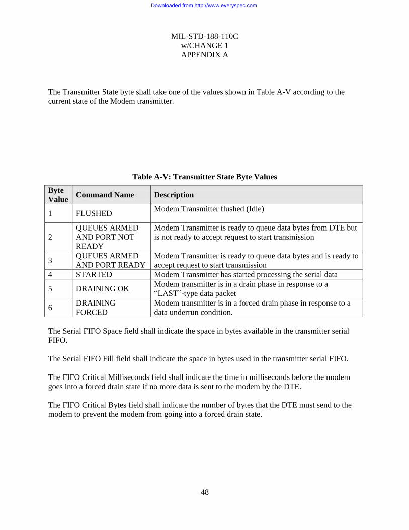
MIL-STD-188-110C
w/CHANGE 1
APPENDIX A
48
The Transmitter State byte shall take one of the values shown in Table A-V according to the
current state of the Modem transmitter.
Table A-V: Transmitter State Byte Values
Byte
Value Command Name Description
1 FLUSHED Modem Transmitter flushed (Idle)
2
QUEUES ARMED
AND PORT NOT
READY
Modem Transmitter is ready to queue data bytes from DTE but
is not ready to accept request to start transmission
3 QUEUES ARMED
AND PORT READY
Modem Transmitter is ready to queue data bytes and is ready to
accept request to start transmission
4 STARTED Modem Transmitter has started processing the serial data
5 DRAINING OK Modem transmitter is in a drain phase in response to a
“LAST”-type data packet
6 DRAINING
FORCED
Modem transmitter is in a forced drain phase in response to a
data underrun condition.
The Serial FIFO Space field shall indicate the space in bytes available in the transmitter serial
FIFO.
The Serial FIFO Fill field shall indicate the space in bytes used in the transmitter serial FIFO.
The FIFO Critical Milliseconds field shall indicate the time in milliseconds before the modem
goes into a forced drain state if no more data is sent to the modem by the DTE.
The FIFO Critical Bytes field shall indicate the number of bytes that the DTE must send to the
modem to prevent the modem from going into a forced drain state.
Downloaded from http://www.everyspec.com
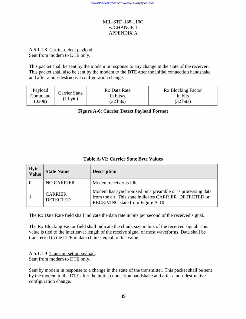
MIL-STD-188-110C
w/CHANGE 1
APPENDIX A
49
A.5.1.1.8 Carrier detect payload.
Sent from modem to DTE only.
This packet shall be sent by the modem in response to any change in the state of the receiver.
This packet shall also be sent by the modem to the DTE after the initial connection handshake
and after a non-destructive configuration change.
Payload
Command
(0x08)
Carrier State
(1 byte)
Rx Data Rate
in bits/s
(32 bits)
Rx Blocking Factor
in bits
(32 bits)
Figure A-6: Carrier Detect Payload Format
Table A-VI: Carrier State Byte Values
Byte
Value State Name Description
0 NO CARRIER Modem receiver is Idle
1 CARRIER
DETECTED
Modem has synchronized on a preamble or is processing data
from the air. This state indicates CARRIER_DETECTED or
RECEIVING state from Figure A-10.
The Rx Data Rate field shall indicate the data rate in bits per second of the received signal.
The Rx Blocking Factor field shall indicate the chunk size in bits of the received signal. This
value is tied to the interleaver length of the receive signal of most waveforms. Data shall be
transferred to the DTE in data chunks equal to this value.
A.5.1.1.9 Transmit setup payload.
Sent from modem to DTE only.
Sent by modem in response to a change in the state of the transmitter. This packet shall be sent
by the modem to the DTE after the initial connection handshake and after a non-destructive
configuration change.
Downloaded from http://www.everyspec.com
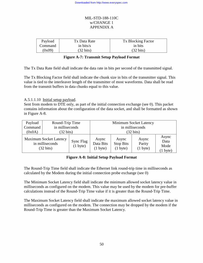
MIL-STD-188-110C
w/CHANGE 1
APPENDIX A
50
Payload
Command
(0x09)
Tx Data Rate
in bits/s
(32 bits)
Tx Blocking Factor
in bits
(32 bits)
Figure A-7: Transmit Setup Payload Format
The Tx Data Rate field shall indicate the data rate in bits per second of the transmitted signal.
The Tx Blocking Factor field shall indicate the chunk size in bits of the transmitter signal. This
value is tied to the interleaver length of the transmitter of most waveforms. Data shall be read
from the transmit buffers in data chunks equal to this value.
A.5.1.1.10 Initial setup payload.
Sent from modem to DTE only, as part of the initial connection exchange (see 0). This packet
contains information about the configuration of the data socket, and shall be formatted as shown
in Figure A-8.
Payload
Command
(0x0A)
Round-Trip Time
in milliseconds
(32 bits)
Minimum Socket Latency
in milliseconds
(32 bits)
Maximum Socket Latency
in milliseconds
(32 bits)
Sync Flag
(1 byte)
Async
Data Bits
(1 byte)
Async
Stop Bits
(1 byte)
Async
Parity
(1 byte)
Async
Data
Mode
(1 byte)
Figure A-8: Initial Setup Payload Format
The Round-Trip Time field shall indicate the Ethernet link round-trip time in milliseconds as
calculated by the Modem during the initial connection probe exchange (see 0)
The Minimum Socket Latency field shall indicate the minimum allowed socket latency value in
milliseconds as configured on the modem. This value may be used by the modem for pre-buffer
calculations instead of the Round-Trip Time value if it is greater than the Round-Trip Time.
The Maximum Socket Latency field shall indicate the maximum allowed socket latency value in
milliseconds as configured on the modem. The connection may be dropped by the modem if the
Round-Trip Time is greater than the Maximum Socket Latency.
Downloaded from http://www.everyspec.com

MIL-STD-188-110C
w/CHANGE 1
APPENDIX A
51
Table A-VII: Synchronous Flag Byte Values
Byte
Value State Name Description
0 ASYNCHRONOUS
Operate socket in asynchronous mode. When in this mode, the
modem shall convert the data stream into an asynchronous bit
stream (see 0)
1 SYNCHRONOUS Standard synchronous socket mode of operation. When this
mode is enabled, the four following bytes shall be set to 0
Table A-VIII: Async Setup Fields Byte Values
Byte
Value Data Bits Field Stop Bits Field Parity Field
0 5 DATA BITS 1 STOP BIT NO PARITY BIT
1 6 DATA BITS 2 STOP BITS EVEN PARITY BIT
2 7 DATA BITS (reserved) ODD PARITY BIT
3 8 DATA BITS (reserved) (reserved)
Table A-IX: Async Data Mode Field
Byte
Value State Name Description
0 STANDARD MODE Sends all start, stop and parity bits over the air
1 DATA ONLY MODE Sends only the data bits over the air
A.5.1.2 TCP socket interface protocol.
A.5.1.2.1 Initial Connection Operation
Immediately after the Data terminal (DTE) device establishes a TCP-streaming connection to the
modem, both the modem and DTE shall each send a CONNECT packet with version number set
to 12 (see 0). If the CONNECT packet is not received within 3 seconds of the socket
Downloaded from http://www.everyspec.com

MIL-STD-188-110C
w/CHANGE 1
APPENDIX A
52
establishment, the entity that timed out (DTE or modem) shall terminate the TCP connection by
closing the TCP socket.
After receiving a correct CONNECT packet, the modem or DTE shall validate the version
numbers by immediately sending a CONNECT_ACK packet with version number set to 12 (see
0). If the CONNECT_ACK packet is not received within 3 seconds of the CONNECT packet
transmission, the entity that timed out (DTE or modem) shall terminate the TCP connection.
If the version is not 12 for any of the above packets, the TCP connection shall be terminated by
the DTE or modem. The modem shall terminate the TCP connection if any timeout (as stated
above) or packet failures occur during the initial connection phase.
Once the connection is established, the modem shall send a CONNECTION_PROBE packet to
the DTE. The DTE shall immediately respond to the packet with another
CONNECTION_PROBE packet. If the modem does not receive a CONNECTION_PROBE
from the DTE within 6 seconds of the CONNECTION_PROBE transmission, it shall terminate
the TCP connection.
The modem shall then send the following packets to the DTE:
1. Initial Setup Packet: The modem takes the time taken between the transmission of the
CONNECTION_PROBE and the reception of the CONNECTION_PROBE from the DTE
and saves it in the Round-Trip Time field. The rest of the settings are obtained from the
Modem Data Socket configuration (user configured using a mechanism beyond the scope of
this Appendix.)
2. Transmit Setup Packet: The data rate and blocking factor fields are obtained from the
waveform configuration (user configured).
3. Transmit Status Packet: The state shall be set to FLUSHED and all other fields except for
“Serial FIFO space” shall be set to 0
4. Carrier Detect Packet: If the modem is not currently receiving, the payload shall indicate NO
CARRIER with all other fields set to 0. If the modem was receiving when the socket was
established, the payload shall indicate CARRIER DETECTED and the Receive Rate and
Receive Blocking Factor fields shall indicate the detected received waveform parameters.
A.5.1.2.2 Connection Keep-Alive
After successful completion of the Initial Connection protocol (see 0), when no packet (status,
control or data) has been sent for a period of 2 seconds (by the DTE or modem), a keep-
alive packet shall be sent. The keep-alive packet shall be a DATA type packet (see 0) with no
payload (0 bytes).
When any DATA type packet (including the 0 byte keep-alive packet) is received by the DTE or
Modem, a timeout timer is reset. If this timeout timer reaches 30 seconds, the TCP connection is
terminated by the entity (DTE or modem) whose timeout has reached 30 seconds.
Downloaded from http://www.everyspec.com
MIL-STD-188-110C
w/CHANGE 1
APPENDIX A
53
A.5.1.2.3 Error Handling
Any packet received by the DTE or Modem that fails the header or payload CRC check shall be
silently dropped as if the packet was never received.
In the event of a protocol error for which a response is not specified elsewhere in this appendix
(e.g., receipt of a reserved or unimplemented command, or receipt of a payload-bearing packet
before the initial connection has been established), an ERROR type packet (see 0) shall be
returned by the receiving device, and that device shall terminate the TCP connection by closing
the TCP socket.
A.5.1.2.4 Modem Configuration Changes
Modifying the modem configuration while the data socket connection is established may cause
the modem to terminate the TCP connection. When this happens, the DTE should detect the TCP
socket closure, re-establish the TCP connection and perform a new initial connection handshake.
Downloaded from http://www.everyspec.com

MIL-STD-188-110C
w/CHANGE 1
APPENDIX A
54
A.5.1.2.5 Full Duplex Modem Transmitter operation
The Initial Connection handshake must be successfully completed before data can be sent from
the DTE to the modem.
a.
Figure A-9: Sending Modem States
The sending process from the DTE to the modem shall proceed as follows:
1. Before sending a TRANSMIT_ARM command packet to the modem, the DTE should wait
until it receives a transmit status packet from the modem indicating a FLUSHED state. If a
TRANSMIT_ARM command packet is sent when the modem is not in the FLUSHED state,
the modem shall send a Transmit Status Packet to the DTE indicating the modem‟s current
state.
2. The DTE sends a TRANSMIT_ARM packet to the modem to arm the modem‟s transmit
queues.
3. The modem shall respond with a transmit status packet of either (see 0)
QUEUES_ARMED_AND_PORT_NOT_READY or QUEUES_ARMED_AND_PORT_
READY if the packet is accepted. Otherwise, repeat from step 1.
4. The DTE sends at least three blocking factors of data packets to pre-fill the modem‟s
interleaver queue (waveform and Ethernet link jitter dependent). Data packets shall be sent
Disconnected Flushed Wait for
Armed
Connect
Disconnect
DTE sends ARM
command
Ready
Modem sends Queues
Armed and Port Ready
status
DTE sends pre-fill data
packets followed by a
START command
DTE may send
CONTINUATION
data packets
Modem finishes transmission
LAST packet delivered to modem
Started
Draining
OK
Draining
Forced
Modem interleaver
emptied before LAST
packet delivered to
modem
Downloaded from http://www.everyspec.com

MIL-STD-188-110C
w/CHANGE 1
APPENDIX A
55
using proper packet order as described in 0. The DTE may send fewer than three blocking
factors of data packets if a FIRST_AND_LAST or a LAST packet is sent.
5. The DTE sends a TRANSMIT_START packet after receiving a transmit status packet with
QUEUES_ARMED_AND_PORT_READY state to start the transmission.
6. If the transmission has started, the modem shall respond with a transmit status packet with
state STARTED.
7. The DTE should wait for a TRANSMIT_STATUS packet to arrive from the modem. If the
state of the packet is not STARTED, the DTE should wait at least 10 milliseconds and repeat
step 5. This may happen when the modem is in receive-master half-duplex mode (see 0).
8. When the modem is in the STARTED or DRAINING state, it shall send transmit status
packets to the DTE indicating the number of queued bytes and number of spaces for bytes in
the modem‟s transmitter‟s queue at least every 2 seconds.
9. At any time, the client may request a transmit status packet by sending a Request Tx Status
packet.
10. Data packets that are in transit to the modem are not included in the calculation of the queue
size. Packets shall not be inserted into the queue if the number of free bytes in the queue is
less than the maximum packet data size. This shall cause the TCP socket on the DTE to block
until the modem‟s queue frees up.
11. If the critical bytes parameter of the transmit setup packet is non-zero, the modem shall
receive from the DTE at least that number of bytes before the critical milliseconds parameter
expires, or the modem shall transition into a DRAINING_FORCED state. This shall cause
the modem to send a TRANSMIT_UNDERRUN Tx Data NACK packet to the DTE.
12. When the modem is in the STARTED state, if a packet is processed with the packet order set
to ORDER_FIRST_AND_LAST or ORDER_LAST, and if the modem transmitter has not
transitioned into a DRAINING_FORCED state, transmit status packets shall be issued with
the DRAINING_OK state.
13. After the modem transmitter has finished sending all the user data to the DTE, the modem
transmitter shall transition into the FLUSHED state.
While in any states shown in Figure A-9, if the TCP connection is terminated by either the DTE
or the modem (from an error or a timeout), the modem transmitter shall immediately transition
into the DISCONNECTED state.
Downloaded from http://www.everyspec.com
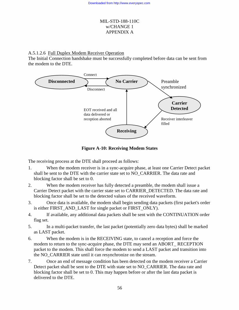
MIL-STD-188-110C
w/CHANGE 1
APPENDIX A
56
A.5.1.2.6 Full Duplex Modem Receiver Operation
The Initial Connection handshake must be successfully completed before data can be sent from
the modem to the DTE.
Figure A-10: Receiving Modem States
The receiving process at the DTE shall proceed as follows:
1. When the modem receiver is in a sync-acquire phase, at least one Carrier Detect packet
shall be sent to the DTE with the carrier state set to NO_CARRIER. The data rate and
blocking factor shall be set to 0.
2. When the modem receiver has fully detected a preamble, the modem shall issue a
Carrier Detect packet with the carrier state set to CARRIER_DETECTED. The data rate and
blocking factor shall be set to the detected values of the received waveform.
3. Once data is available, the modem shall begin sending data packets (first packet's order
is either FIRST_AND_LAST for single packet or FIRST_ONLY).
4. If available, any additional data packets shall be sent with the CONTINUATION order
flag set.
5. In a multi-packet transfer, the last packet (potentially zero data bytes) shall be marked
as LAST packet.
6. When the modem is in the RECEIVING state, to cancel a reception and force the
modem to return to the sync-acquire phase, the DTE may send an ABORT_ RECEPTION
packet to the modem. This shall force the modem to send a LAST packet and transition into
the NO_CARRIER state until it can resynchronize on the stream.
7. Once an end of message condition has been detected on the modem receiver a Carrier
Detect packet shall be sent to the DTE with state set to NO_CARRIER. The data rate and
blocking factor shall be set to 0. This may happen before or after the last data packet is
delivered to the DTE.
Disconnected No Carrier
Carrier
Detected
Receiving
Connect
Disconnect
Preamble
synchronized
Receiver interleaver
filled
EOT received and all
data delivered or
reception aborted
Downloaded from http://www.everyspec.com
MIL-STD-188-110C
w/CHANGE 1
APPENDIX A
57
While in any states shown in Figure A-10, if the TCP connection is terminated by either the DTE
or the modem (from an error or a timeout), the modem receiver shall immediately transition into
the DISCONNECTED state.
A.5.1.2.7 Half Duplex Operation.
In addition to the Full-Duplex receiver and transmitter operation described in 0 and 0, half-
duplex operation shall also be supported. In half-duplex mode, the modem shall only be able to
receive or transmit at any one time (not both at the same time). In addition, the modem shall also
support the following two modes of operation when operating in half-duplex mode:
1. Transmitter Master
2. Receiver Master
A.5.1.2.7.1 Half Duplex Transmitter Master
When in half-duplex transmitter master mode, the modem shall prioritize the transmitter
operation.
If a reception is currently in progress (CARRIER_DETECTED or RECEIVING states from
Figure A-10), and the transmitter is in the FLUSHED state (see Figure A-9), the DTE may send
a TRANSMIT_ARM command and initiate a transfer as shown in 0. Once the modem is
transitioned into the STARTED state, the modem receiver shall immediately return to the NO
CARRIER state (see Figure A-10), which shall abort the reception. The modem shall then send a
LAST data packet to the DTE and send a Carrier Detect packet with state set to NO_CARRIER
to the DTE.
While the modem transmitter is in the STARTED, DRAINING_OK or DRAINING_FORCED
states (Figure A-9), the modem receiver shall remain in the NO_CARRIER state (Figure A-10).
A.5.1.2.7.2 Half Duplex Receiver Master
When in half-duplex receiver master mode, the modem shall prioritize the receiver operation if a
transmission is not currently in progress.
If a reception is currently in progress (CARRIER_DETECTED or RECEIVING states from
Figure A-10), and the transmitter is in the FLUSHED state (see Figure A-9), the DTE may send
a TRANSMIT_ARM command to the modem. While the modem reception is in progress, the
modem shall transition into the QUEUES_ARMED_AND_PORT_NOT_READY state and
remain in that state until the modem receiver transitions into the NO_CARRIER state.
While the modem is in the QUEUES_ARMED_AND_PORT_NOT_READY state, the DTE
may send data packets to be queued onto the modem but may not send a TRANSMIT_START
command to the modem. If the DTE sends a TRANSMIT_START command to the modem, the
Downloaded from http://www.everyspec.com

MIL-STD-188-110C
w/CHANGE 1
APPENDIX A
58
modem shall send another Transmit Status packet with state set to QUEUES_ARMED_AND_
PORT_NOT_READY to the DTE. In this case, once the modem receiver transitions into the
NO_CARRIER state, the modem shall send a Transmit Status packet with state set to
QUEUES_ARMED_AND_PORT_READY to the DTE. The DTE may then send a
TRANSFER_STARTED command to the modem and perform a data transfer as shown in 0.
The receiver master mode shall only prevent the modem from transitioning into the STARTED
state while the receiver is in the CARRIER_DETECTED or RECEIVING state. Once the
modem transmitter is in the STARTED, DRAINING_OK or DRAINING_FORCED states (see
Figure A-9), the modem receiver shall remain in the NO_CARRIER state (see Figure A-10).
A.5.1.2.8 Data Socket Modes
The TCP data socket interface (TDSI) supports both synchronous and asynchronous operation.
The differences between the two data modes are explained in this section. The mode of operation
is specified by the modem and is sent to the DTE during the connection handshake.
A.5.1.2.8.1 Synchronous
While the TDSI is in the synchronous mode of operation the data shall be transferred from the
DTE to the modem at the specified data rate to prevent the modem from going into a
TRANSMIT_UNDERRUN state. The data is also not byte-synchronized in this mode of
operation, which means that the DTE shall perform bit-synchronization to byte-align the
received data stream.
A.5.1.2.8.2 Asynchronous
The asynchronous mode of operation supports two sub-modes of operation:
1. Standard Mode: All asynchronous data bits are transmitted over the air
2. Data Only Mode: Only the data bits are transmitted over the air
A.5.1.2.8.2.1 Asynchronous Standard Mode (Send-All)
When the Async Data Mode is set to STANDARD MODE, the sending modem shall convert the
data stream into an asynchronous bit stream (adding start bits, stop bits and parity bits) with the
specified settings before sending the data over the air. The receiving modem shall decode the
received asynchronous stream from the air and convert it to a standard data stream before
sending it to the DTE.
In this mode, the DTE does not have to keep a steady data stream to the modem. If the modem‟s
transmit queues are emptied, it shall transmit stop bits over the air until more data is available for
transmission up to a user specified keep-alive time. If no data is received by the modem for a
period longer than the keep-alive time, the modem shall transition into a
TRANSMIT_UNDERRUN state.
Data is always exchanged in the data packets using 8-bit byte alignment. If the ASYNC DATA
BITS parameter is set to N DATA BITS, where N is less than 8, the least significant N bits of
each 8-bit data bytes of the Data Payload shall be used for the OTA stream.
Downloaded from http://www.everyspec.com

MIL-STD-188-110C
w/CHANGE 1
APPENDIX A
59
A.5.1.2.8.2.2 Asynchronous Data-Only Mode
When the Async Data Mode is set to DATA ONLY MODE, only the data bits are transmitted
over the air. In this mode, the ASYNC DATA BITS shall be 8 DATA BITS and the ASYNC
PARITY shall be NO PARITY. Since no control bits are sent over the air, the data shall be
transferred from the DTE to the modem at the specified data rate to prevent the modem from
going into a TRANSMIT_UNDERRUN state.
The difference between asynchronous DATA ONLY MODE and synchronous is that for async
mode, the modem receiver does not need to buffer data at the start of a reception before sending
it to the DTE. The data is sent directly to the DTE as it is decoded from the waveform. For the
synchronous mode, the modem shall buffer the data to keep the constant data rate specified by
the receiving waveform before starting the data stream to the DTE.
A.5.2 UDP socket interface (UDSI).
A.5.2.1 Control connection.
UDP packets shall not be exchanged between the DTE and modem until a TCP Remote Control
Interface (RCI) connection is established from the DTE to the modem. The RCI connection shall
be used by the modem to obtain the DTE source address and port number that will be used for
the UDP data stream. The protocol used for the RCI is beyond the scope of this appendix.
A.5.2.2 UDP socket interface packet format.
Each UDP packet exchanged between the DTE and the modem shall consist of a 4-byte header,
optionally followed by a variable-length payload. A 16 bit CRC shall be appended to the end of
each packet. The total packet length, including the 2 byte CRC, shall be less than or equal to
1226 bytes; at most 1220 payload bytes may be sent in a single packet.
Packet
Header
(4 bytes)
Payload
(0 to 1220 bytes)
Packet
CRC
(16 bits)
Figure A-11: UDSI packet format
The payload length may be inferred from the packet type (see Table A-X). The Packet CRC
shall be computed (see 0) for the Packet Header bytes and Payload Bytes (if present).
A.5.2.3 UDP socket interface packet header format.
Each packet shall begin with a header consisting of the following fields:
Downloaded from http://www.everyspec.com
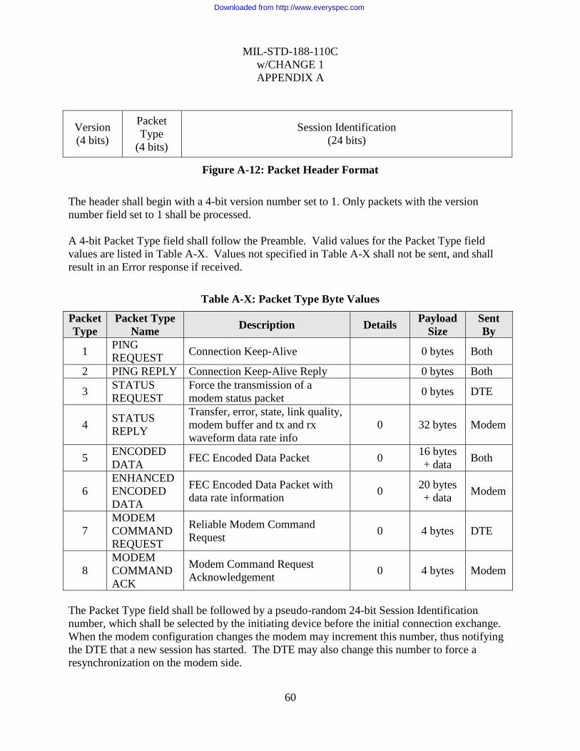
MIL-STD-188-110C
w/CHANGE 1
APPENDIX A
60
Version
(4 bits)
Packet
Type
(4 bits)
Session Identification
(24 bits)
Figure A-12: Packet Header Format
The header shall begin with a 4-bit version number set to 1. Only packets with the version
number field set to 1 shall be processed.
A 4-bit Packet Type field shall follow the Preamble. Valid values for the Packet Type field
values are listed in Table A-X. Values not specified in Table A-X shall not be sent, and shall
result in an Error response if received.
Table A-X: Packet Type Byte Values
Packet
Type
Packet Type
Name Description Details
Payload
Size
Sent
By
1 PING
REQUEST Connection Keep-Alive 0 bytes Both
2 PING REPLY Connection Keep-Alive Reply 0 bytes Both
3 STATUS
REQUEST
Force the transmission of a
modem status packet 0 bytes DTE
4 STATUS
REPLY
Transfer, error, state, link quality,
modem buffer and tx and rx
waveform data rate info
0 32 bytes Modem
5 ENCODED
DATA FEC Encoded Data Packet 0
16 bytes
+ data Both
6
ENHANCED
ENCODED
DATA
FEC Encoded Data Packet with
data rate information 0
20 bytes
+ data Modem
7
MODEM
COMMAND
REQUEST
Reliable Modem Command
Request 0 4 bytes DTE
8
MODEM
COMMAND
ACK
Modem Command Request
Acknowledgement 0 4 bytes Modem
The Packet Type field shall be followed by a pseudo-random 24-bit Session Identification
number, which shall be selected by the initiating device before the initial connection exchange.
When the modem configuration changes the modem may increment this number, thus notifying
the DTE that a new session has started. The DTE may also change this number to force a
resynchronization on the modem side.
Downloaded from http://www.everyspec.com

MIL-STD-188-110C
w/CHANGE 1
APPENDIX A
61
A.5.2.4 Packet types.
A.5.2.4.1 Status reply payload.
(Sent from modem to DTE only.) This message shall be sent by the modem when the state of any
field changes or if a Status Reply packet has not been sent for 500 milliseconds. The DTE may
also request a transmission of this packet from the modem by sending a STATUS_ REQUEST
packet.
Packet Sequence
Number
(16 bits)
Current Transfer
Identification
(16 bit)
Reserved
(16 bits)
Error
Vector
(8 bits)
Status
Vector
(8 bits)
Packets Dropped
(16 bits)
Jitter
(16 bits)
Transmit Queue Fill
(32 bits)
Transmit Queue Space
(32 bits)
OTA Receive Bit Rate
(24 bits)
MSB of
next field
OTA Receive
Blocking Factor
(24 bits)
OTA Transmit Bit Rate
(24 bits)
OTA Transmit Blocking Factor
(24 bits)
Figure A-13: Status Reply Payload Format
Packet Sequence Number (16-bit number sent in network byte order): The modem shall
increment the sequence number of the status packet for every successive packet. The Packet
sequence number shall be computed modulo 65536 so that 0xFFFF, when incremented by 1 shall
become 0. This shall be used by the DTE to detect out-of-order and duplicate status packets. The
DTE shall calculate the modulo 65536 difference between the packet sequence number and the
last received status sequence number. If this difference is less than zero when treated as a signed
16 bit value, the DTE shall ignore the status packet. This results in packets being ignored if the
sequence number falls within the 0xFFFF/2 values previous to the last received sequence
number. The DTE shall always accept the first status packet.
Current Transfer Identification (16-bit number sent in network byte order): The transfer ID shall
be used by the DTE to identify which transfer the status packet pertains to, when sending many
short transfers over a long latency network.
The modem shall set the current transfer identification number of the status packet to the transfer
ID of the current transmission.
Reserved: This field shall be set to 0
Downloaded from http://www.everyspec.com

MIL-STD-188-110C
w/CHANGE 1
APPENDIX A
62
The Error Vector shall be a bit field formatted as follows:
Reserved
(bits 7-5)
Not in
Control
(bit 4)
Rx
Underrun
(bit 3)
Rx
Overrun
(bit 2)
Tx
Underrun
(bit 1)
Tx
Overrun
(bit 0)
Figure A-14: Error Vector Format
When the modem is not in an error state all bits in this vector shall be 0. The reserved bits shall
always be 0. The following table provides a description of the error bits:
Table A-XI: Error Vector Bit Values
Bit Bit Name Description
0 TX OVERRUN When set to 1, The modem‟s transmit buffers have overflowed.
This happens when the DTE sends data to the modem too fast. The
transfer will be terminated and the modem‟s transmitter will return
to the FLUSHED state
1 TX UNDERRUN When set to 1, The modem‟s transmitter buffers have emptied
unexpectedly. This happens when the DTE does not send data fast
enough to the modem. The transfer will be terminated and the
modem‟s transmitter will return to the FLUSHED state
2 RX OVERRUN When set to 1, The modem‟s receive buffers have overflowed.
This should not happen during normal operation
3 RX UNDERRUN When set to 1, The modem‟s receive buffers have emptied
unexpectedly. This should not happen during normal operation
4 NOT IN
CONTROL
When set to 1, The modem has received data from the DTE but the
DTE does not have “Control Mode” enabled on the RCI
connection. No data will be accepted by the modem
The Status Vector shall be a bit field formatted as follows:
Reserved
(bit 7)
Receiver State
(bits 6-5)
Carrier
Detect
(bit 4)
Transmitter State
(bits 3-1)
In
Control
(bit 0)
Figure A-15: Status Vector Format
The reserved bits shall always be 0.
The following table provides a description of the status bits:
Downloaded from http://www.everyspec.com

MIL-STD-188-110C
w/CHANGE 1
APPENDIX A
63
Table A-XII: Status Vector Bit Values
Bit(s) Bit Name Description
6-5 RECEIVER
STATE
2-bit value (MSB is bit 6): Reflects the current state of the modem
receiver (see Table )
4 CARRIER
DETECT
When set to 1, the modem‟s receiver has synchronized on a
preamble or is processing data from the air
3-1 TRANSMITTER
STATE
3-bit value (MSB is bit 3): Reflects the current state of the modem
transmitter (see Table )
0 In Control
When set to 1, the modem has received the “Control Mode”
request from the DTE on its RCI connection. The client may now
send data to the modem
Table A-XIII: Status Vector Receiver State Values
Bit
Value Status Name Description
00 FLUSHED Modem Receiver is flushed (Idle)
01 STARTED Modem Receiver has started processing user data
Table A-XIV: Status Vector Transmitter State Values
Bit
Value Status Name Description
000 FLUSHED Modem Transmitter flushed (Idle)
001 QUEUEING Modem Transmitter has started receiving data from the DTE but
has not started OTA transmission yet
010 STARTED Modem Transmitter has started OTA transmission
011 DRAINING
Modem Transmitter is in a drain phase in response to a “Last”
type data packet, an underrun condition or an unrecoverable data
error (too many missed packets)
Packets Dropped (16-bit number sent in network byte order): The number of packets that have
been missed (dropped) by the modem for the current transmission. Packets are dropped either
because of a network error (packet error) or because the packet arrives late. The dropped packets
are recovered by the modem (using FEC) unless the modem transmitter has unexpectedly
changed to a DRAINING state. This value may be used by the DTE as an Ethernet link quality
value.
Downloaded from http://www.everyspec.com

MIL-STD-188-110C
w/CHANGE 1
APPENDIX A
64
Jitter: The Ethernet packet jitter in milliseconds as seen by the modem for the current
transmission. This value shall be the standard deviation of: the inter-packet arrival time minus
the expected arrival time (uses the packet timestamp for calculations). This value is calculated
over a window of 100 packets and is based on the standard deviation of the difference between
the time of reception of a packet and the timestamp in the packet.
Transmit Queue Fill: Space in bytes used in the transmitter serial queue.
Transmit Queue Space: Space in bytes available in the transmitter serial queue.
OTA Receive Bit Rate: Over-the-air data rate in bits per second of the received signal.
OTA Receive Blocking Factor: Chunk size in bits of the received signal. This value is tied to the
interleaver length of the receive signal of most waveforms. Data shall be written to the DTE in
data chunks equal to this value.
OTA Transmit Bit Rate: Over-the-air data rate in bits per second of the transmitter waveform.
OTA Transmit Blocking Factor: Chunk size in bits of the transmitter waveform. This value is
tied to the interleaver length of the transmit signal of most waveforms. Data shall be written to
the DTE in data chunks equal to this value.
Encoded data payload.
Between 0 and 1200 bytes of FEC/interleaved data may be sent to/from the modem using an
encoded data payload (see 0 for more information on the FEC/Interleaver scheme). If N is the
number of data bytes to be sent, the 16 + N information bytes of a data packet shall consist of:
Transfer Identification
(16 bits)
Packet Sequence Number
(16 bits)
Control Vector
(8 bits)
FEC
Type
(4 bits)
Inter-
leaver
Type
(4 bits)
FEC N Value
(8 bits)
FEC K Value
(8 bits)
Data Length
(16 bits)
Reserved
(16 bits)
Timestamp
(32 bits)
Data
(0 to 1200 bytes)
Figure A-16: Encoded Data Payload Format
Downloaded from http://www.everyspec.com

MIL-STD-188-110C
w/CHANGE 1
APPENDIX A
65
Transfer Identification (16-bit number sent in network byte order): A pseudo-random number
shall be selected and maintained for the duration of a transfer. This number shall be incremented
every time a new transfer is started. The transfer identification number shall be computed
modulo 65536 so that 0xFFFF, when incremented by 1 shall become 0.
Packet Sequence Number (16-bit number sent in network byte order): Each successive encoded
data packet has an incremented sequence number associated to it. The packet sequence number
shall be computed modulo 65536 so that 0xFFFF, when incremented by 1 shall become 0. This
number is initialized to 0 for each new transfer. This is used by the DTE and modem to detect
duplicate data packets and reorder out-of-order packets.
The Control Vector is a bit field as follows:
Reserved
(bits 7-3)
Holdoff Flag
(bit 2)
Last Inter-
leaver Set
(bit 1)
First Inter-
leaver Set
(bit 0)
Figure A-17: Control Vector Format
The reserved bits shall always be 0. The following table provides an explanation of the control
bits:
Table A-XV: Control Vector Bit Values
Bit Bit Name Description
2 HOLDOFF FLAG
May be used by the DTE to affect the modem‟s
auto-prebuffer handling (default 0 for auto-
prebuffer handling). See 0.
1 LAST INTERLEAVER SET
When set to 1, this packet belongs to the last
interleaver set of a transfer. An interleaver set is
defined as N packets, where N is the FEC N value.
0 FIRST INTERLEAVER SET When set to 1, this packet belongs to the first
interleaver set of a transfer
FEC Type (4-bits): The UDP data socket currently only supports the “Reed Solomon with
Erasures” (see 0) FEC Type, which is type 1. Only packets with FEC Type set to 1 shall be
accepted.
Interleaver Type (4-bits): The UDP data socket currently only supports the “Standard FEC-
matched byte-wise Interleaver” Interleaver Type, which is type 1. Only packets with Interleaver
Type set to 1 shall be accepted.
Downloaded from http://www.everyspec.com

MIL-STD-188-110C
w/CHANGE 1
APPENDIX A
66
FEC N Value (8-bits): The total number of bytes per FEC codeword.
FEC K Value (8-bits): The number of user bytes per FEC codeword.
Data Length (16-bit number sent in network byte order): The number of data bytes stored in the
Encoded Data Payload packet (immediately following the Timestamp bytes).
Reserved: This field shall be set to 0
Timestamp field shall indicate the A timestamp in milliseconds taken at the source just before
the packet is sent to the UDP socket. The timestamp may be calculated from the system time as
follows:
struct timeval tv;
unsigned int nTimestamp;
gettimeofday(&tv, NULL);`
nTimestamp = ((tv.tv_sec % 3600) * 1000000) + tv.tv_usec;
A.5.2.4.3 Enhanced encoded data payload.
(Sent from modem to DTE only) Between 0 and 1200 bytes of FEC/interleaved data may be
sent to/from the modem using an enhanced encoded data payload (see 0 for more information on
the FEC/Interleaver scheme). If N is the number of data bytes to be sent, the 20 + N information
bytes of a data packet consist of:
Transfer Identification
(16 bits)
Packet Sequence Number
(16 bits)
Control Vector
(8 bits)
FEC
Type
(4 bits)
Inter-
leaver
Type
(4 bits)
FEC N Value
(8 bits)
FEC K Value
(8 bits)
Data Length
(16 bits) Data Bit Rate
(24 bits)
LSB of Data Bit Rate Data Blocking Factor
(24 bits)
Timestamp
(32 bits)
Data
(0 to 1200 bytes)
FigureA-18: Encoded Data Payload Format
Downloaded from http://www.everyspec.com

MIL-STD-188-110C
w/CHANGE 1
APPENDIX A
67
The Enhanced Encoded Data Payload has all the same fields as the Encoded Data Payload. Extra
fields are provided to supply data rate information. The modem shall send an interleaver set of
Extended Encoded Data packets at the start of each transfer and continue with Encoded Data
packets if required.
See 0 for descriptions of the following fields:
Transfer Identification
Packet Sequence Number
Control Vector
FEC Type
Interleaver Type
FEC N Value
FEC K Value
Data Length
Timestamp
Data Bit Rate (24-bit number sent in network byte order): Data rate in bits per second of the
received data stream. This value shall not change for the remainder of the transfer.
Data Blocking Factor (24-bit number sent in network byte order): Chunk size in bits of the
received signal. This value is tied to the interleaver length of the receive signal of most
waveforms. Data shall be written to the DTE in data chunks equal to this value. This value shall
not change for the remainder of the transfer.
Modem command request payload.
(Sent from DTE to Modem only) This packet may be sent by the DTE to instruct the modem to
execute a particular command. Since this command is reliable, if the DTE does not get a Modem
Command ACK packet in response to a Modem Command Request, it shall re-send the
command. See 0.
Packet Sequence Number
(16 bits)
Command
(8 bits)
Reserved
(8 bits)
FigureA-19: Modem Command Request Payload Format
Packet Sequence Number (16-bit number sent in network byte order): Each successive encoded
Modem Command Request packet shall have an incremented sequence number associated to it.
This number shall be initialized to 0 for the first command sent. If a packet is retransmitted, it
shall keep the same sequence number as when it was initially transmitted.
Downloaded from http://www.everyspec.com

MIL-STD-188-110C
w/CHANGE 1
APPENDIX A
68
The following table shows the list of commands that shall be supported by the protocol:
Table A-XVI: Command Byte Values
The modem shall ignore command request packets with unsupported command values.
Reserved: This field shall be set to 0
A.5.2.4.5 Modem command acknowledgement payload.
(Sent from Modem to DTE only) This packet shall be sent by the modem in response to a
Modem Command Request packet.
Packet Sequence Number
(16 bits)
Reserved
(16 bits)
Figure A-20: Modem Command Acknowledgement Payload Format
Packet Sequence Number (16-bit number sent in network byte order): The sequence number of
the Modem Command Request that is being acknowledged
Reserved: This field shall be set to 0
A.5.2.5 Data FEC and interleaving.
A Reed Solomon code is used to encode data so that data from late or missing data packets can
be reconstructed by the receiver, whether it is Modem or DTE. Data to be sent are used to fill the
data portion of an interleaver block and RS parity symbols are used to fill the remainder of the
interleaver block.
The interleaver block is shown pictorially below, where the M * N symbols of the interleaver
block are composed of rows consisting of RS encoded data with N-K parity symbols for each K
data symbols. Note that the RS symbol size used, 4 bits, is one nibble or one half of a byte, so
that in the diagram below, the cells with diagonal stripes represent the lower nibble of each byte.
Data is written into the interleaver in rows. That is, the first row of the interleaver shown below,
which contains the first Reed Solomon codeword is formed from the upper nibble of the first K
data bytes. The second row of the interleaver, containing the second Reed Solomon codeword is
formed using the lower nibbles of the first K data bytes. Data is transmitted, one interleaver at a
time, with data being read out in columns. The precise details are described in this section.
Byte
Value Command Name Description
1 ABORT
RECEPTION
Force the modem to return to the Sync-Acquire phase. This will
cause the modem to issue a LAST packet and switch to a
FLUSHED state until it can resynchronize to the stream
Downloaded from http://www.everyspec.com

MIL-STD-188-110C
w/CHANGE 1
APPENDIX A
69
K
N
N-K
M
Figure A-21: FEC Interleaver
To allow the Modem or DTE to recover from late data packets or data packet losses, the UDSI
shall provide forward error correction coding using Shortened Reed-Solomon (RS) error
correction coding with erasures using 4-bit symbols, whose generator polynomial is:
g(x) = x4 + a
l3 x
3 + a
6x
2 + a
3x + a
10;
where a is a non zero element of the Galois field (GF)(24) formed as the field of polynomials
over GF(2) modulo x4 + x + 1.
For each data stream, an appropriate set of shortened N, shortened K and L parameters is chosen
to maximize error recovery while minimizing the amount of pre-buffering, delay and
overhead that is added by using the FEC and Interleaving scheme. The parameters are dependent
on the Data Rate and Blocking Factor (tied to the waveform interleaver) of the waveform using
the following formula:
Table A-XVII: FEC Coding Length Table
Data Rate (bps) N K Shortened
N
Shortened
K
50 to 2400 15 11 6 2
3200 to 28800 15 12 7 4
32000 to 76800 15 12 8 5
Downloaded from http://www.everyspec.com
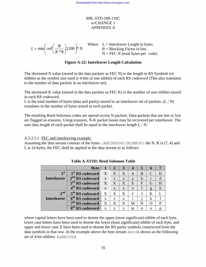
MIL-STD-188-110C
w/CHANGE 1
APPENDIX A
70
Figure A-22: Interleaver Length Calculation
The shortened N value (stored in the data packets as FEC N) is the length in RS Symbols (or
nibbles as the symbol size used is 4 bits or one nibble) of each RS codeword (This also translates
to the number of data packets in an interleaver set).
The shortened K value (stored in the data packets as FEC K) is the number of user nibbles stored
in each RS codeword.
L is the total number of bytes (data and parity) stored in an interleaver set of packets. (L / N)
translates to the number of bytes stored in each packet.
The resulting Reed-Solomon codes are spread across N packets. Data packets that are late or lost
are flagged as erasures. Using erasures, N-K packet losses may be recovered per interleaver. The
user data length of each packet shall be equal to the interleaver length L / N.
A.5.2.5.1 FEC and interleaving example.
Assuming the data stream consists of the bytes {ABCDEFGHIJKLMNOP} the N, K is (7, 4) and
L is 14 bytes, the FEC shall be applied to the data stream to as follows:
Table A-XVIII: Reed-Solomon Table
Byte 1 2 3 4 5 6 7
1st
Interleaver
1st RS codeword X X X A B C D
2nd
RS codeword x x x a b c d
3rd
RS codeword X X X E F G H
4th
RS codeword x x x e f g h
2nd
Interleaver
5th
RS codeword X X X I J K L
6th
RS codeword x x x i j k l
7th
RS codeword X X X M N O P
8th
RS codeword x x x m n o p
where capital letters have been used to denote the upper (most significant) nibble of each byte,
lower case letters have been used to denote the lower (least significant) nibble of each byte, and
upper and lower case X have been used to denote the RS parity symbols constructed from the
data symbols in that row. In the example above the byte stream ABCD is shown as the following
set of 4-bit nibbles: AaBbCcDd
NK
BceilL *1200,
8*min
Where L = Interleaver Length in bytes
B = Blocking Factor in bits
N = FEC N (total bytes per code) K = FEC K (data bytes
per code)
Downloaded from http://www.everyspec.com
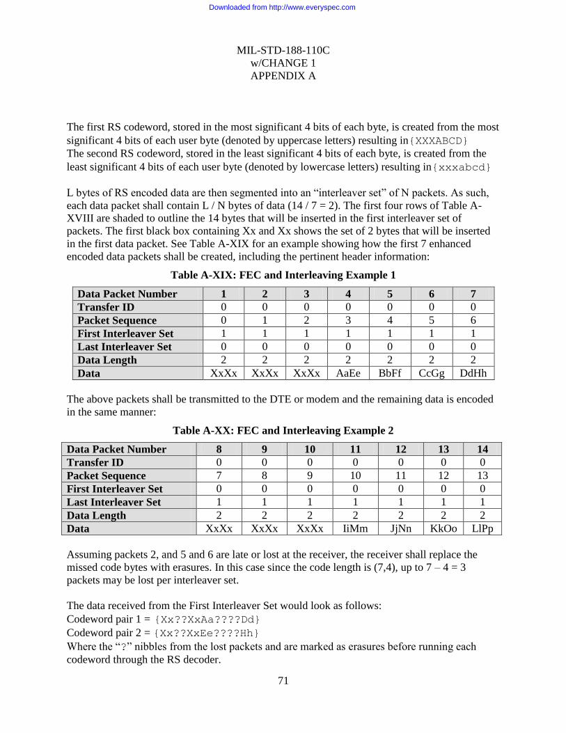
MIL-STD-188-110C
w/CHANGE 1
APPENDIX A
71
The first RS codeword, stored in the most significant 4 bits of each byte, is created from the most
significant 4 bits of each user byte (denoted by uppercase letters) resulting in{XXXABCD}
The second RS codeword, stored in the least significant 4 bits of each byte, is created from the
least significant 4 bits of each user byte (denoted by lowercase letters) resulting in{xxxabcd}
L bytes of RS encoded data are then segmented into an “interleaver set” of N packets. As such,
each data packet shall contain L / N bytes of data (14 / 7 = 2). The first four rows of Table A-
XVIII are shaded to outline the 14 bytes that will be inserted in the first interleaver set of
packets. The first black box containing Xx and Xx shows the set of 2 bytes that will be inserted
in the first data packet. See Table A-XIX for an example showing how the first 7 enhanced
encoded data packets shall be created, including the pertinent header information:
Table A-XIX: FEC and Interleaving Example 1
Data Packet Number 1 2 3 4 5 6 7
Transfer ID 0 0 0 0 0 0 0
Packet Sequence 0 1 2 3 4 5 6
First Interleaver Set 1 1 1 1 1 1 1
Last Interleaver Set 0 0 0 0 0 0 0
Data Length 2 2 2 2 2 2 2
Data XxXx XxXx XxXx AaEe BbFf CcGg DdHh
The above packets shall be transmitted to the DTE or modem and the remaining data is encoded
in the same manner:
Table A-XX: FEC and Interleaving Example 2
Data Packet Number 8 9 10 11 12 13 14
Transfer ID 0 0 0 0 0 0 0
Packet Sequence 7 8 9 10 11 12 13
First Interleaver Set 0 0 0 0 0 0 0
Last Interleaver Set 1 1 1 1 1 1 1
Data Length 2 2 2 2 2 2 2
Data XxXx XxXx XxXx IiMm JjNn KkOo LlPp
Assuming packets 2, and 5 and 6 are late or lost at the receiver, the receiver shall replace the
missed code bytes with erasures. In this case since the code length is (7,4), up to 7 – 4 = 3
packets may be lost per interleaver set.
The data received from the First Interleaver Set would look as follows:
Codeword pair 1 = {Xx??XxAa????Dd}
Codeword pair 2 = {Xx??XxEe????Hh} Where the “?” nibbles from the lost packets and are marked as erasures before running each
codeword through the RS decoder.
Downloaded from http://www.everyspec.com

MIL-STD-188-110C
w/CHANGE 1
APPENDIX A
72
Codeword pair 1 shall be decoded as {AaBbCcDd} and Codeword pair 2 as {EeFfGgHh}.
A.5.2.5.2 End of message detection.
The following EOM string shall be used to delineate the end of the user data portion of a data
stream:
{0x4B, 0x65, 0xA5, 0xB2, 0x26, 0xD2, 0xD3, 0x69}
The above string of bytes shall be appended to the end of the user data stream. The bytes shall be
added before running the FEC encoder and Interleaver (i.e. the EOM bytes are also FECed). Any
remaining bytes (to fill the rest of the last interleaver) shall be padded with 0x00. Note that the
EOM string may span multiple interleaver sets. Upon reception, the EOM string and following
padding bytes shall be detected and removed from the data stream.
A.5.2.6 Protocol operation.
A.5.2.6.1 Initial connection operation.
Since UDP is a connectionless protocol, no connection is required before the data terminal
(DTE) can send UDP data to the modem. However, the DTE shall establish a control
connection, and obtain write lockout of the modem before sending data. The modem shall use
the source address of the control connection to ensure that UDP data is only sent to, and received
from a single DTE.
A.5.2.6.2 Connection keep-alive.
As a means to detect network failures, keep-alive ping packets shall be regularly sent from the
DTE or the modem. Ping packets shall be sent to the modem at a rate of once every five
seconds. The keep-alive packet shall be a PING REQUEST type packet (see 0) with no payload
(0 bytes).
When any PING REPLY type packet is received by the DTE or Modem, a timeout timer shall be
reset. If the timeout timer reaches 30 seconds, the modem shall ignore any further data sent by
the DTE and shall abort the current transmission. The modem shall only accept further data sent
by the DTE once a PING REPLY is received, or the DTE sends data with a new session ID.
A.5.2.6.3 Error handling.
Packets received containing error(s) in the header or payload CRC shall be ignored. Packets of
unrecognized type or incorrect format shall be ignored. Duplicate packets shall also be ignored.
Both the modem and DTE are responsible for re-ordering the packets they receive, and
discarding packets that arrive late (after the interleaver set has been decoded).
Downloaded from http://www.everyspec.com

MIL-STD-188-110C
w/CHANGE 1
APPENDIX A
73
The modem shall decode interleaver sets as they come, replacing any missing packets with
erasures. If an interleaver set is unable to be decoded by the modem, an end of message will be
sent over the air and the modem will transition to a DRAINING state.
Likewise, the DTE shall determine a maximum time to wait for a packet before considering it
lost. This timeout shall be calculated as the amount of time to transmit the user data of the
interleaver over the air ((FEC K * L * 8 bits/byte) / over air data rate (bps)), plus the expected
latency of the UDP socket, plus the maximum expected jitter of the UDP socket. If the packet is
considered lost, the DTE shall replace it with an erasure before performing the FEC decoding.
A.5.2.6.4 Modem configuration changes.
Modifying the modem configuration while the data socket is in use may cause the current
transmission to be terminated. When this happens, the modem shall update its session ID, and
return to a flushed transmitter state.
A.5.2.6.5 Modem transmitter operation.
The DTE must gain control of the modem before it can successfully send data.
Figure A-23: Sending Modem States
The sending process from the DTE to the modem shall proceed as follows:
1. Before sending commands, the DTE must wait until it receives a modem transmit status
packet from the modem indicating a FLUSHED state.
Modem has pre-buffered
enough data, and DTE
holdoff flag not set
No Master
Flushed Queueing
Control No Control
DTE sends data
Started Draining
LAST interleaver set delivered
to modem or FEC decode error
Modem finishes
transmission
LAST interleaver set
delivered to modem
Downloaded from http://www.everyspec.com
MIL-STD-188-110C
w/CHANGE 1
APPENDIX A
74
2. The Modem will transition to a QUEUEING state when it begins to receive data from the
DTE.
3. The modem will automatically detect when it has enough data queued, and will begin to
transmit. At this point, the modem will transition to a STARTED state. The DTE may
prevent the modem from automatically starting by setting the hold off flag in the control
vector of the encoded data packets. The modem will remain in a queueing state until this flag
is cleared (in which case automatic pre-buffer detection resumes) or the last interleaver set is
received by the modem (in which case the modem will transition to a draining state).
4. When the last interleaver set is received by the modem, it will transition into a DRAINING
state.
5. When the modem is in the STARTED or DRAINING state, it shall periodically send status
packets to the DTE indicating the number of queued bytes and number of spaces for bytes in
the udp receive buffer. The udp receive buffer is a packet based buffer, so all packets are
considered to be of max length (1200) for the purposes of the queued/space bytes calculation.
The DTE shall use longer interleavers and lower N/K ratios at higher data rates. See Table
A-XXI for a list of recommended FEC settings.
6. At anytime, the client may request a status packet by sending a Status Request packet.
7. Data packets that are in transit to the modem are not included in the calculation of the queue
size. Packets will not be inserted into the queue if there is no remaining space in the queue.
In this case the packet will be dropped.
8. The data sent from the DTE to the modem shall be paced such that the amount of user data
sent to the modem over a given period of time is equal to the amount of data the modem is
capable of sending over air in the same period of time.
9. If the modem is unable to decode data due to insufficient packets, or too much packet loss, it
will force an end of transmission and transition to a DRAINING state.
10. After the transmitter has finished sending all the radio data, the modem transmitter will
transition into the FLUSHED state.
Downloaded from http://www.everyspec.com

MIL-STD-188-110C
w/CHANGE 1
APPENDIX A
75
Table A-XXI: Recommended FEC Settings
Data Rate (bps) FEC N FEC K Interleaver
50 6 2 1
75 6 2 1
150 6 2 1
300 6 2 2
600 6 2 4
1200 6 2 8
1800 6 2 12
2400 6 2 15
3200 7 4 10
3600 7 4 12
4800 7 4 15
6400 7 4 20
7680 7 4 24
8000 7 4 25
9600 7 4 30
12800 7 4 40
14400 7 4 45
16000 7 4 50
19200 7 4 60
24000 7 4 75
25600 7 4 80
28800 7 4 90
32000 8 5 32
38400 8 5 39
48000 8 5 48
51200 8 5 52
64000 8 5 64
76800 8 5 77
80000 8 5 80
96000 8 5 96
128000 8 5 128
192000 8 5 192
256000 8 5 256
384000 8 5 384
Downloaded from http://www.everyspec.com

MIL-STD-188-110C
w/CHANGE 1
APPENDIX A
76
A.5.2.6.6 Modem receiver operation.
The DTE must gain control of the modem before the modem can send data to the DTE.
Figure A-24: Receiving Modem States
The receiving process at the DTE shall proceed as follows:
1. When the modem receiver is in a sync-acquire phase, status reply packets shall be sent to the
DTE with the carrier detect flag set to 0.
2. When the modem receiver has fully detected a preamble, the modem shall issue a status reply
packet with the carrier detect flag set to 1.
3. Once data is available, the modem shall begin sending data packets. The first interleaver
shall be sent using ENHANCED ENCODED DATA packets indicating the rate and blocking
factor for the reception. This interleaver set shall have the first interleaver flag set to 1. Any
subsequent interleaver sets shall be sent using ENCODED DATA packets. The last
interleaver set will have the last interleaver flag set to 1.
4. Once an end of message condition has been detected on the modem receiver a status reply
packet shall be sent to the DTE with the carrier detect packet set to 0. This may happen
before or after the last data packet is delivered to the DTE.
5. When the modem completes processing the received data, it shall send a status reply packet
to the DTE indicating that the receiver is in a FLUSHED state. This may happen before or
after the last data packet is delivered to the DTE.
A.5.2.6.7 Modem commands.
The DTE may send commands to the modem using a modem command request packet at any
time to affect its operation. Currently the only supported command is the receiver abort
command. When the modem receives a command, it shall send a modem command ack
indicating that it has processed the command. Because the UDP protocol is unreliable, the DTE
No Master Carrier
Detect=0
(FLUSHED)
Carrier
Detect=1
STARTED
No Control
Preamble
received
Receiver interleaver
filled
EOT received/
All data delivered
Control
Downloaded from http://www.everyspec.com

MIL-STD-188-110C
w/CHANGE 1
APPENDIX A
77
may be required to retransmit commands using a pre-determined timeout with an exponential
back off.
A.5.2.6.8 Data socket modes.
The UDP data socket supports a synchronous and asynchronous operation. The differences
between the two data modes are explained in this section. The modem and DTE must be
configured to use the same mode.
A.5.2.6.8.1 Synchronous.
The synchronous mode of operation is the standard mode of operation. The data must be
transferred from the DTE to the modem at the specified data rate to prevent the modem from
dropping packets or terminating the transmission due to a FEC decode error. The data is also not
byte-synchronized in this mode of operation, which means that the DTE must perform bit-
synchronization to byte-align the received data stream.
A.5.2.6.8.2 Asynchronous.
The asynchronous mode of operation with the Async Data Mode set to STANDARD MODE will
cause the modem to convert the data stream into an asynchronous bit stream (adding start bits,
stop bits and parity bits) with the specified settings before sending the data over the air. The
modem will also decode the received asynchronous stream from the air, stripping the start, stop
and parity bits from the data stream before sending it to the DTE.
In this case, the DTE does not have to keep a steady data stream to the modem. If the modem‟s
transmit queues are emptied, it will transmit stop bits over the air until more data is available for
transmission.
Data is always exchanged in the data packets using 8-bit byte alignment. If the ASYNC DATA
BITS parameter is set to 5 DATA BITS, the least significant 5-bits of each 8-bit data bytes of the
Data Payload will be used for the OTA stream.
When the Async Data Mode is set to DATA ONLY MODE, only the data bits are transmitted
over the air. In this mode, the ASYNC DATA BITS must be 8 DATA BITS and the ASYNC
PARITY must be NO PARITY. Since no control bits are sent over the air, the data must be
transferred from the DTE to the modem at the specified data rate to prevent the modem from
going into a TX_UNDERRUN state.
The difference between asynchronous DATA ONLY MODE and synchronous is that for async
mode, the modem receiver does not need to buffer data at the start of a reception before sending
it to the DTE. The data is sent directly to the DTE as it is decoded from the waveform. For the
synchronous mode, the modem must buffer the data to keep the constant data rate specified by
the receiving waveform before starting the data stream to the DTE.
Downloaded from http://www.everyspec.com
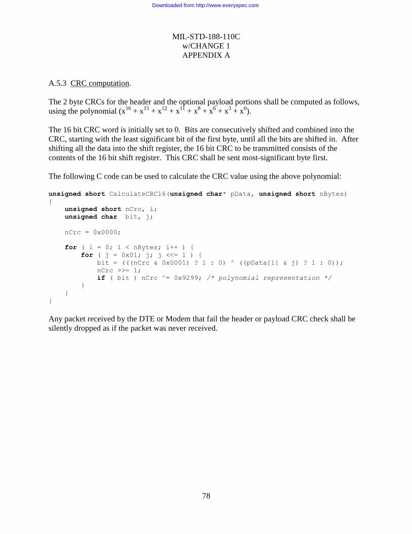
MIL-STD-188-110C
w/CHANGE 1
APPENDIX A
78
A.5.3 CRC computation.
The 2 byte CRCs for the header and the optional payload portions shall be computed as follows,
using the polynomial (x16
+ x15
+ x12
+ x11
+ x8 + x
6 + x
3 + x
0).
The 16 bit CRC word is initially set to 0. Bits are consecutively shifted and combined into the
CRC, starting with the least significant bit of the first byte, until all the bits are shifted in. After
shifting all the data into the shift register, the 16 bit CRC to be transmitted consists of the
contents of the 16 bit shift register. This CRC shall be sent most-significant byte first.
The following C code can be used to calculate the CRC value using the above polynomial:
unsigned short CalculateCRC16(unsigned char* pData, unsigned short nBytes)
{
unsigned short nCrc, i;
unsigned char bit, j;
nCrc = 0x0000;
for ( i = 0; i < nBytes; i++ ) {
for ( j = 0x01; j; j <<= 1 ) {
bit = (((nCrc & 0x0001) ? 1 : 0) ^ ((pData[i] & j) ? 1 : 0));
nCrc >>= 1;
if ( bit ) nCrc ^= 0x9299; /* polynomial representation */
}
}
}
Any packet received by the DTE or Modem that fail the header or payload CRC check shall be
silently dropped as if the packet was never received.
Downloaded from http://www.everyspec.com
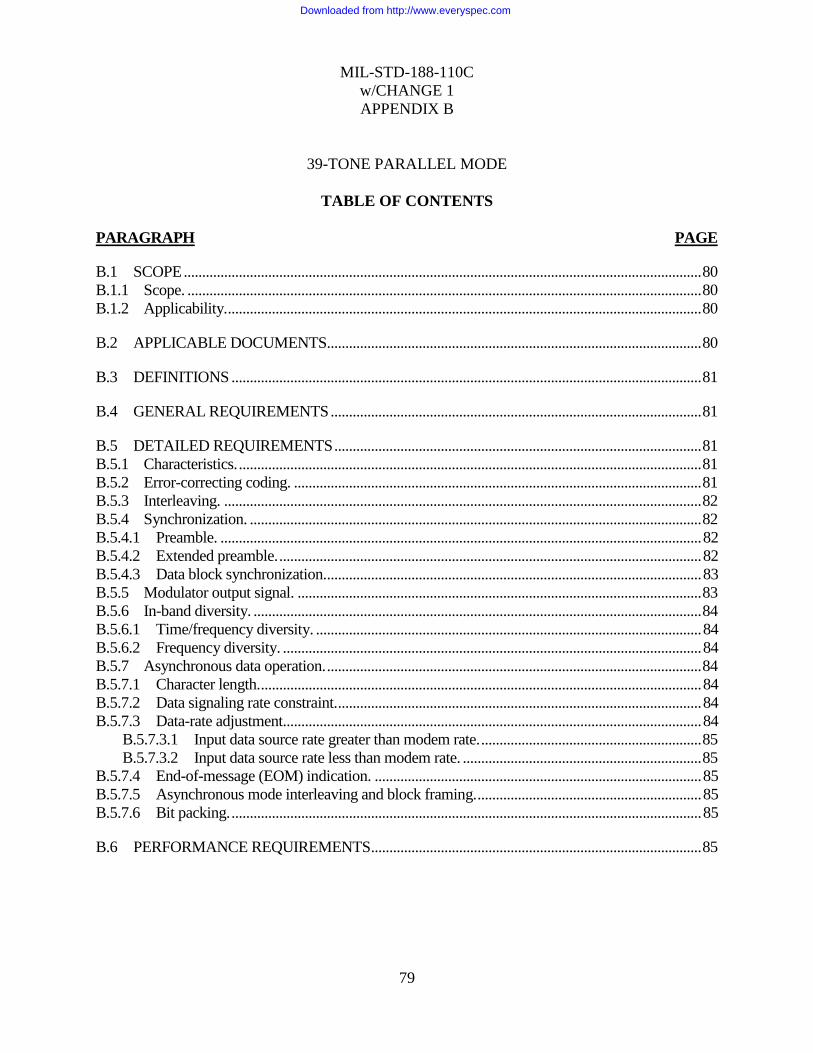
MIL-STD-188-110C
w/CHANGE 1
APPENDIX B
79
39-TONE PARALLEL MODE
TABLE OF CONTENTS
PARAGRAPH PAGE
B.1 SCOPE ............................................................................................................................................. 80
B.1.1 Scope. ............................................................................................................................................ 80
B.1.2 Applicability. ................................................................................................................................. 80
B.2 APPLICABLE DOCUMENTS...................................................................................................... 80
B.3 DEFINITIONS ................................................................................................................................ 81
B.4 GENERAL REQUIREMENTS ..................................................................................................... 81
B.5 DETAILED REQUIREMENTS .................................................................................................... 81
B.5.1 Characteristics. .............................................................................................................................. 81
B.5.2 Error-correcting coding. ............................................................................................................... 81
B.5.3 Interleaving. .................................................................................................................................. 82
B.5.4 Synchronization. ........................................................................................................................... 82
B.5.4.1 Preamble. ................................................................................................................................... 82
B.5.4.2 Extended preamble. ................................................................................................................... 82
B.5.4.3 Data block synchronization. ...................................................................................................... 83
B.5.5 Modulator output signal. .............................................................................................................. 83
B.5.6 In-band diversity. .......................................................................................................................... 84
B.5.6.1 Time/frequency diversity. ......................................................................................................... 84
B.5.6.2 Frequency diversity. .................................................................................................................. 84
B.5.7 Asynchronous data operation. ...................................................................................................... 84
B.5.7.1 Character length. ........................................................................................................................ 84
B.5.7.2 Data signaling rate constraint. ................................................................................................... 84
B.5.7.3 Data-rate adjustment.................................................................................................................. 84
B.5.7.3.1 Input data source rate greater than modem rate. ............................................................ 85
B.5.7.3.2 Input data source rate less than modem rate. ................................................................. 85
B.5.7.4 End-of-message (EOM) indication. ......................................................................................... 85
B.5.7.5 Asynchronous mode interleaving and block framing. ............................................................. 85
B.5.7.6 Bit packing. ................................................................................................................................ 85
B.6 PERFORMANCE REQUIREMENTS .......................................................................................... 85
Downloaded from http://www.everyspec.com
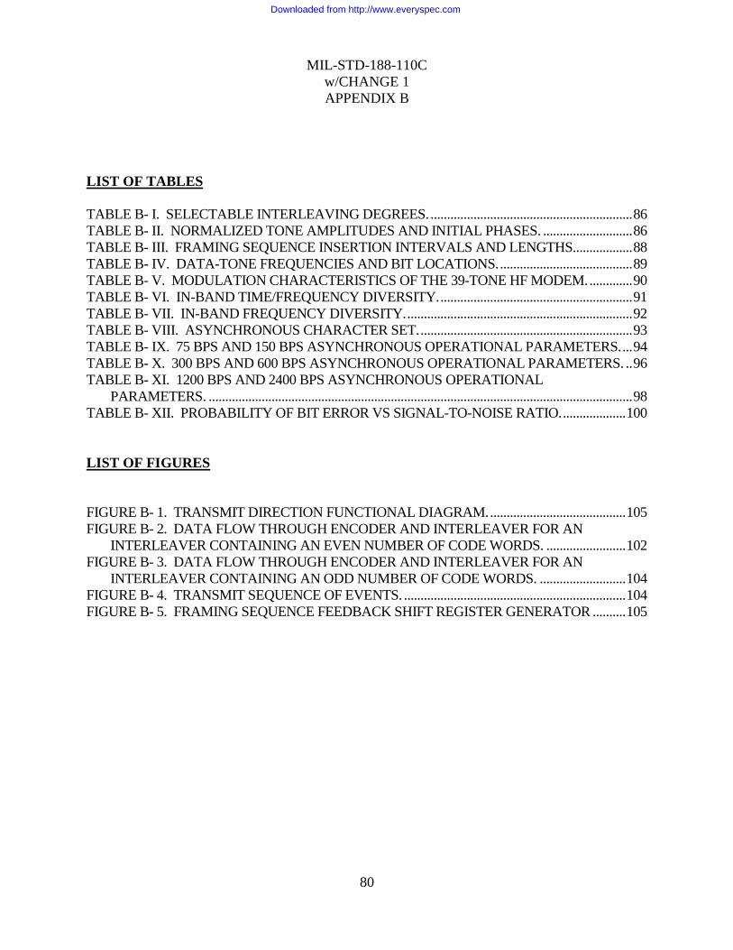
MIL-STD-188-110C
w/CHANGE 1
APPENDIX B
80
LIST OF TABLES
TABLE B- I. SELECTABLE INTERLEAVING DEGREES. ............................................................. 86
TABLE B- II. NORMALIZED TONE AMPLITUDES AND INITIAL PHASES. ........................... 86
TABLE B- III. FRAMING SEQUENCE INSERTION INTERVALS AND LENGTHS.................. 88
TABLE B- IV. DATA-TONE FREQUENCIES AND BIT LOCATIONS. ........................................ 89
TABLE B- V. MODULATION CHARACTERISTICS OF THE 39-TONE HF MODEM. ............. 90
TABLE B- VI. IN-BAND TIME/FREQUENCY DIVERSITY. .......................................................... 91
TABLE B- VII. IN-BAND FREQUENCY DIVERSITY. .................................................................... 92
TABLE B- VIII. ASYNCHRONOUS CHARACTER SET. ................................................................ 93
TABLE B- IX. 75 BPS AND 150 BPS ASYNCHRONOUS OPERATIONAL PARAMETERS. ... 94
TABLE B- X. 300 BPS AND 600 BPS ASYNCHRONOUS OPERATIONAL PARAMETERS. .. 96
TABLE B- XI. 1200 BPS AND 2400 BPS ASYNCHRONOUS OPERATIONAL
PARAMETERS. ................................................................................................................................ 98
TABLE B- XII. PROBABILITY OF BIT ERROR VS SIGNAL-TO-NOISE RATIO. ................... 100
LIST OF FIGURES
FIGURE B- 1. TRANSMIT DIRECTION FUNCTIONAL DIAGRAM. ......................................... 105
FIGURE B- 2. DATA FLOW THROUGH ENCODER AND INTERLEAVER FOR AN
INTERLEAVER CONTAINING AN EVEN NUMBER OF CODE WORDS. ........................ 102
FIGURE B- 3. DATA FLOW THROUGH ENCODER AND INTERLEAVER FOR AN
INTERLEAVER CONTAINING AN ODD NUMBER OF CODE WORDS. .......................... 104
FIGURE B- 4. TRANSMIT SEQUENCE OF EVENTS. ................................................................... 104
FIGURE B- 5. FRAMING SEQUENCE FEEDBACK SHIFT REGISTER GENERATOR .......... 105
Downloaded from http://www.everyspec.com

MIL-STD-188-110C
w/CHANGE 1
APPENDIX B
81
B.1 SCOPE
B.1.1 Scope.
This appendix describes the 39-tone parallel mode.
B.1.2 Applicability.
This appendix is optional, and not recommended for new systems; however, when the 39-tone
parallel mode is used, it shall be implemented in accordance with this appendix.
B.2 APPLICABLE DOCUMENTS
This section is not applicable to this appendix.
B.3 DEFINITIONS
See section 3.
B.4 GENERAL REQUIREMENTS
The mode specified herein uses 39 orthogonal subcarrier tones in the audio frequency band with
quadrature differential phase shift keying (QDPSK) modulation for bit synchronous data
transmission. In the transmit direction, this mode (see figure B-1) (1) accepts UNKNOWN serial
binary data at its line side data input port, (2) performs forward error correction (FEC) encoding
and interleaving, and (3) converts the resulting bit stream into QDPSK data tones at the
modulator output port. The modulation rate of the modulator output is constant for all data rates.
In-band diversity of varying degrees is used at data rates below 1200 bits per second (bps). A
means is provided for synchronization of the signal element and interleaved data block timing. A
40th unmodulated tone is used for correcting frequency offsets introduced by Doppler shift or
radio equipment instability. In a like manner, the receive direction (1) accepts QDPSK data tones
at its input, (2) converts them into the transmitted serial bit stream, (3) performs deinterleaving
and FEC decoding, and (4) makes the resulting data stream available at its line-side output port.
B.5 DETAILED REQUIREMENTS
B.5.1 Characteristics.
In this section, detailed requirements are given for the waveform characteristics for which
knowledge is needed to achieve over-the-air interoperability. These characteristics are error
correction coding, interleaving, synchronization, modulator output signal, in-band
time/frequency diversity, and asynchronous data operation.
B.5.2 Error-correcting coding.
All UNKNOWN input data shall have redundant bits added to it, prior to modulation, for the
purpose of correcting errors introduced by the transmission medium. The added bits shall be
computed by a shortened Reed-Solomon (15,11) block code, whose generator polynomial is:
Downloaded from http://www.everyspec.com

MIL-STD-188-110C
w/CHANGE 1
APPENDIX B
82
g(x) = x4 + a
l3 x
3 + a
6x
2 + a
3x + a
10;
where a is a non zero element of the Galois field (GF)(24) formed as the field of polynomials
over GF(2) module x4 + x + 1.
For input signaling rates of 2400 bps, the code shall be shortened to (14,10). Otherwise, the code
shall be shortened to (7,3).
B.5.3 Interleaving.
The mode shall perform block interleaving for the purpose of providing time separation between
contiguous symbols of a code word. Selectable interleaving degrees for the data rates is shown in
Table B-I shall be provided. For a data signaling rate of 2400 bps, the selection shall consist of
eight degrees. At data signaling rates below 2400 bps, four degrees for each bit rate shall be
provided as shown in Table B-I. The input data stream shall be loaded into the interleaver buffer
as described by figures B-2 and B-3.
B.5.4 Synchronization.
A means shall be provided whereby the receive demodulator process achieves time alignment
with both signal element and code word timing. Frame synchronization shall be acquired within
680 milliseconds (ms). The transmit sequence of events is shown on figure B-4.
B.5.4.1 Preamble.
Prior to the transmission of data, a three part preamble shall be transmitted. Part one shall last for
14 signal element periods and consist of four equal amplitude unmodulated data tones of 787.5,
1462.5, 2137.5, and 2812.5 hertz (Hz). Part two shall last for 8 signal element periods and
consist of three modulated data tones of 1125.0, 1800.0, and 2475.0 Hz. The three data tones of
part two shall be advanced 180 degrees at the boundary of each data signal element. Part three
shall last for one signal element period and consist of all 39 data tones plus the Doppler
correction tone. This last part establishes the starting phase reference for subsequent signal
element periods. During all parts of the preamble, the transmitted level of the composite signals
shall have a root-mean-square (rms) value within ±1 decibel (dB) of the rms value of the
modulator output (39-tone) levels occurring during subsequent data transmission. The tone
phases at the onset of each part of the preamble, along with their normalized amplitudes, shall be
in accordance with Table B-II.
B.5.4.2 Extended preamble.
To improve the probability of synchronization and signal presence detection in low
signal-to-noise ratio situations, the ability to select an extended preamble shall be provided. Part
one of the extended preamble shall last for 58 signal element periods, part two shall last for 27
signal element periods, and part three shall last for 12 signal element periods. In parts one and
two, the data tones shall be as described in the nonextended preamble given above. In part three,
the phase of each data tone shall be set at the onset of each signal element to the phase that it had
at the onset of the first signal element in this part.
Downloaded from http://www.everyspec.com

MIL-STD-188-110C
w/CHANGE 1
APPENDIX B
83
NOTE: When operating with the extended preamble, the minimum doppler correction
shall be ±20 Hz and frame synchronization shall be acquired within 2.5 seconds (s).
B.5.4.3 Data block synchronization.
A set of interleaved code words is known as a super block. Block synchronization (framing) is
the process whereby a receiving demodulator locates super block boundaries. This
synchronization process must occur before proper deinterleaving and decoding can commence.
Framing shall be established and maintained by periodically inserting into the encoded unknown
data bit stream a known pseudo-random sequence. The required sequence is defined by the
primitive polynomial f(x) = x9 + x
7 + x
6 + x
4 + 1, when used in the feedback shift register
configuration shown in figure B-5.
The first insertion of the block framing sequence shall start on the first signal element following
the synchronization preamble. Upon transmission of the last bit of the sequence, the first bit of
the first super block shall be transmitted without interruption. Thereafter, the framing sequence
shall be inserted each time the number of super blocks specified in Table B-III has been
transmitted. Upon transmission of the last bit of the framing sequence, transmission of data bits
shall resume without interruption.
The number of framing bits to be transmitted per insertion varies with data rate and interleaving
degree, and is specified in Table B-III. However, the final bit of the framing sequence shall
always be the first space bit that follows a contiguous block of nine MARK bits. Equivalently,
the final sequence bit shall be the bit generated by the shift register when its present state is
111111111 (binary) or 511 (decimal).
B.5.5 Modulator output signal.
The modulator output shall contain 39 QDPSK data tones (see Table B-IV). The 39 data tones
shall be simultaneously keyed to produce a signal element interval of 22.5 milliseconds (ms) for
each data tone. The composite modulator output shall have a constant modulation rate of 44.44
baud (Bd) for all standard input data signaling rates from 75 to 2400 bps. At input signaling rates
less than 2400 bps, information carried on data tones 1 through 7 shall also be carried on data
tones 33 through 39. The modulator shall also provide the required special preamble tone
combinations used to initiate synchronization and Doppler correction.
During data transmission, the unmodulated Doppler correction tone shall be 6 dB ±1 dB higher
than the normal level of any data tone. All tone frequencies shall maintain an accuracy of ±0.05
Hz. At the onset of each signal element, every data tone shall experience a phase change relative
to its phase at the onset of the previous signal element. The modulator shall partition the bit
stream to be transmitted into 2 bit symbols (dibits) and map them into a phase change of the
appropriate data tone according to Table B-V.
Downloaded from http://www.everyspec.com

MIL-STD-188-110C
w/CHANGE 1
APPENDIX B
84
B.5.6 In-band diversity.
Two selectable methods of in-band diversity for data rates of 75 - 600 bps shall be incorporated
in each modem as follows: a modern method containing both time and frequency diversity, and
a frequency-only diversity method for backward compatibility with older modems. The
requirements given for these methods in the following subparagraphs apply to diversities of
order d, where d = 1200/(data signaling rate).
B.5.6.1 Time/frequency diversity.
Disregarding the redundant data carried on data tones 33 through 39, 64 bits, equally partitioned
into d data words, shall be transmitted during each 22.5 ms signal element. Each data word and
its d-1 copies shall be transmitted on 32/d unique data tones in d different signal elements. If data
word i is being transmitted in a given signal element, the other data words that are to be
transmitted in the same signal element are given by i - k(16/d), where k ranges from l through
d-1 (see Table B-VI).
B.5.6.2 Frequency diversity.
In-band diversity shall be characterized by transmitting a data word and its (d-1) copies in one
signal element (e.g., 22.5 ms time interval). This characterization is according to the tone/bit
assignments shown in Table B-VII.
B.5.7 Asynchronous data operation.
In addition to bit synchronous data transmission, an asynchronous mode shall also be supported.
When operating in the asynchronous mode, the modulator shall accept source data in
asynchronous start/stop character format, and convert it to bit synchronous data prior to FEC
encoding. Conversely, after FEC decoding, the demodulator shall convert bit synchronous data
back into asynchronous format. Also, before FEC encoding, SPACE bits shall replace the start,
stop, and parity bits. After FEC decoding, the start, stop, and parity bits shall be re-generated
before placing the characters in the output data stream.
Otherwise, the mode operates as specified in B.5.1 through B.5.6.2 above.
B.5.7.1 Character length.
A means shall be provided whereby the modulator will accept, and the demodulator will
generate, any of the data characters shown in Table B-VIII.
B.5.7.2 Data signaling rate constraint.
A means shall be provided whereby the selected data signaling rate of the modem is constrained
to not exceed the nominal bit rate of the data input source.
B.5.7.3 Data-rate adjustment.
A means shall be provided whereby differences between data signaling rates of the data input
source and the modem are accommodated with no loss of data or introduction of extraneous data
in the demodulated output.
Downloaded from http://www.everyspec.com

MIL-STD-188-110C
w/CHANGE 1
APPENDIX B
85
B.5.7.3.1 Input data source rate greater than modem rate.
The modem shall maintain a control path to the data source for the purpose of stopping the flow
of data into the modulator. When the modem senses that continued flow of input data will result
in data loss, it shall cause the data source to suspend the transfer of data. Upon sensing that the
threat of data loss has passed, the modem shall allow the transfer of data to resume.
B.5.7.3.2 Input data source rate less than modem rate.
When the modem senses that it is about to exhaust its supply of source data, it shall insert a
special "null" character into the source data bit stream prior to encoding. The null character shall
be formed by making each of its bits a SPACE, and the start, stop, and parity bits a MARK. The
demodulator shall recognize this bit pattern as a null character, and discard it from its data
output.
B.5.7.4 End-of-message (EOM) indication.
Upon reception of the source's final data character, the modulator shall insert a series of EOM
characters into the source data bit stream prior to encoding. The EOM character shall be formed
by making each of its bits a MARK. The number of EOM characters inserted shall range from a
minimum of ten to the number greater than ten required to fill a super block. The demodulator
shall use the arrival of the EOM characters to terminate its data output.
B.5.7.5 Asynchronous mode interleaving and block framing.
The degree of interleaving, and the framing sequence length used in the asynchronous mode,
vary with data signaling rate and character length. With each data rate and character length, four
selectable interleaving degrees shall be provided as shown in tables B-IX, B-X, and B-XI, along
with the corresponding framing sequence length.
B.5.7.6 Bit packing.
An integral number of data characters shall be transmitted between framing sequence
transmissions. Therefore, the number of bits encoded will not always equal the number of bits
received from the data source. In such cases, the modulator shall insert into the source data a
number of fill bits equal to the difference between the number of bits encoded and the number of
bits received (see tables B-IX, B-X, and B-XI). The fill bits shall be located in the bit stream so
that they are the first bits encoded, thereby permitting the remainder of the data transmission to
carry an integral number of data characters.
B.6 PERFORMANCE REQUIREMENTS
The minimum performance of the 39-tone mode employing soft decision decoding and
maximum interleaving, as measured using a baseband HF simulator patterned after the
Watterson Model for channel simulation in accordance with Appendix E, shall be as shown in
Table B-XII.
When testing a modem embedded with a radio, so that only radio frequency (RF) signals are
available for testing, the RF signals must be down-converted to baseband for processing by the
Downloaded from http://www.everyspec.com

MIL-STD-188-110C
w/CHANGE 1
APPENDIX B
86
channel simulator, and the result up-converted to RF for the receiver. In this case, the built-in
radio filters will affect the performance of the modems. Therefore, when testing embedded
modems, the SNR values specified in Table B-XII shall be increased by 2 dB.
TABLE B- I. Selectable interleaving degrees.
Data rate (bps) 75 150 300 600 1200 2400
Interleaving
degree
1 1 1 1 1 1 36
4 9 17 33 63 9 72
12 25 47 99 189 18 144
36 81 153 297 567 27 288
TABLE B- II. Normalized tone amplitudes and initial phases.
Preamble
part
number
Tone freq
(Hz)
Function Normalized
amplitude
Initial phase
(degrees)
1 787.50 Data tone 3 3 0.0
1 1462.50 Data tone 15 3 103.7
1 2137.50 Data tone 27 3 103.7
1 2812.50 Data tone 39 3 0.0
2 1125.00 Data tone 9 4 0.0
2 1800.00 Data tone 21 4 90.0
2 2475.00 Data tone 33 4 0.0
3 393.75 Doppler 2 0.0
3 675.00 Data tone 1 1 0.0
3 731.25 Data tone 2 1 5.6
3 787.50 Data tone 3 1 19.7
3 843.75 Data tone 4 1 42.2
3 900.00 Data tone 5 1 73.1
3 956.25 Data tone 6 1 115.3
3 1012.50 Data tone 7 1 165.9
3 1068.75 Data tone 8 1 225.0
3 1125.00 Data tone 9 1 295.3
3 1181.25 Data tone 10 1 14.1
3 1237.50 Data tone 11 1 101.3
3 1293.75 Data tone 12 1 199.7
3 1350.00 Data tone 13 1 303.8
3 1406.25 Data tone 14 1 59.1
3 1462.50 Data tone 15 1 185.6
3 1518.75 Data tone 16 1 317.8
3 1575.00 Data tone 17 1 101.3
3 1631.25 Data tone 18 1 253.1
3 1687.50 Data tone 19 1 56.3
Downloaded from http://www.everyspec.com

MIL-STD-188-110C
w/CHANGE 1
APPENDIX B
87
Preamble
part
number
Tone freq
(Hz)
Function Normalized
amplitude
Initial phase
(degrees)
3 1743.75 Data tone 20 1 225.0
3 1800.00 Data tone 21 1 45.0
3 1856.25 Data tone 22 1 236.3
3 1912.50 Data tone 23 1 73.1
3 1968.75 Data tone 24 1 281.3
3 2025.00 Data tone 25 1 137.8
3 2081.25 Data tone 26 1 5.6
3 2137.50 Data tone 27 1 239.1
3 2193.75 Data tone 28 1 123.8
3 2250.00 Data tone 29 1 19.7
3 2306.25 Data tone 30 1 281.3
3 2362.50 Data tone 31 1 194.1
3 2418.75 Data tone 32 1 115.3
3 2475.00 Data tone 33 1 45.0
3 2531.25 Data tone 34 1 345.9
3 2587.50 Data tone 35 1 295.3
3 2643.75 Data tone 36 1 253.1
3 2700.00 Data tone 37 1 222.2
3 2756.25 Data tone 38 1 199.7
3 2812.50 Data tone 39 1 185.6
Downloaded from http://www.everyspec.com
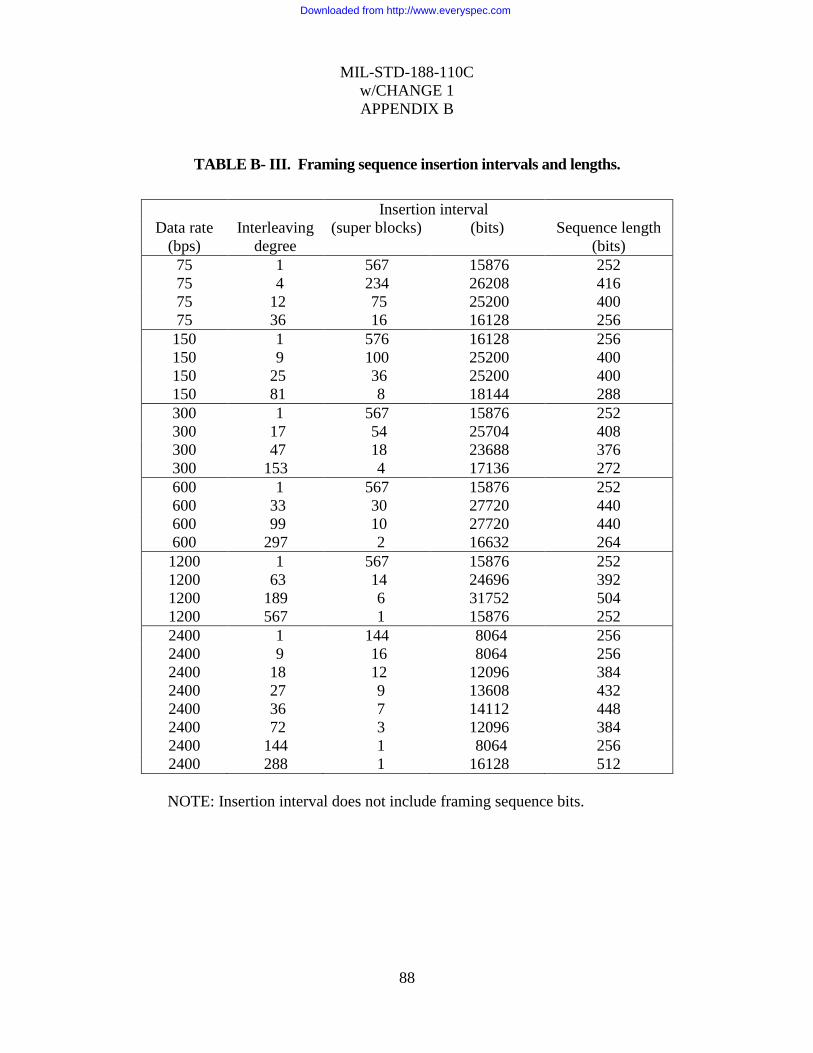
MIL-STD-188-110C
w/CHANGE 1
APPENDIX B
88
TABLE B- III. Framing sequence insertion intervals and lengths.
Insertion interval
Data rate
(bps)
Interleaving
degree
(super blocks) (bits) Sequence length
(bits)
75 1 567 15876 252
75 4 234 26208 416
75 12 75 25200 400
75 36 16 16128 256
150 1 576 16128 256
150 9 100 25200 400
150 25 36 25200 400
150 81 8 18144 288
300 1 567 15876 252
300 17 54 25704 408
300 47 18 23688 376
300 153 4 17136 272
600 1 567 15876 252
600 33 30 27720 440
600 99 10 27720 440
600 297 2 16632 264
1200 1 567 15876 252
1200 63 14 24696 392
1200 189 6 31752 504
1200 567 1 15876 252
2400 1 144 8064 256
2400 9 16 8064 256
2400 18 12 12096 384
2400 27 9 13608 432
2400 36 7 14112 448
2400 72 3 12096 384
2400 144 1 8064 256
2400 288 1 16128 512
NOTE: Insertion interval does not include framing sequence bits.
Downloaded from http://www.everyspec.com

MIL-STD-188-110C
w/CHANGE 1
APPENDIX B
89
TABLE B- IV. Data-tone frequencies and bit locations.
Bit locations
Tone freq(Hz) Function 2400 bps 1200 bps
393.75 Continuous Doppler
675.00 Data tone 1 1 2 1 2
731.25 Data tone 2 3 4 3 4
787.50 Data tone 3 5 6 5 6
843.75 Data tone 4 7 8 7 8
900.00 Data tone 5 9 10 9 10
956.25 Data tone 6 11 12 11 12
1012.50 Data tone 7 13 14 13 14
1068.75 Data tone 8 15 16 15 16
1125.00 Data tone 9 17 18 17 18
1181.25 Data tone 10 19 20 19 20
1237.50 Data tone 11 21 22 21 22
1293.75 Data tone 12 23 24 23 24
1350.00 Data tone 13 25 26 25 26
1406.25 Data tone 14 27 28 27 28
1462.50 Data tone 15 29 30 29 30
1518.75 Data tone 16 31 32 31 32
1575.00 Data tone 17 33 34 33 34
1631.25 Data tone 18 35 36 35 36
1687.50 Data tone 19 37 38 37 38
1743.75 Data tone 20 39 40 39 40
1800.00 Data tone 21 41 42 41 42
1856.25 Data tone 22 43 44 43 44
1912.50 Data tone 23 45 46 45 46
1968.75 Data tone 24 47 48 47 48
2025.00 Data tone 25 49 50 49 50
2081.25 Data tone 26 51 52 51 52
2137.50 Data tone 27 53 54 53 54
2193.75 Data tone 28 55 56 55 56
2250.00 Data tone 29 57 58 57 58
2306.25 Data tone 30 59 60 59 60
2362.50 Data tone 31 61 62 61 62
2418.75 Data tone 32 63 64 63 64
2475.00 Data tone 33 65 66 1 2
2531.25 Data tone 34 67 68 3 4
2587.50 Data tone 35 69 70 5 6
2643.75 Data tone 36 71 72 7 8
2700.00 Data tone 37 73 74 9 10
2756.25 Data tone 38 75 76 11 12
2812.50 Data tone 39 77 78 13 14
Downloaded from http://www.everyspec.com
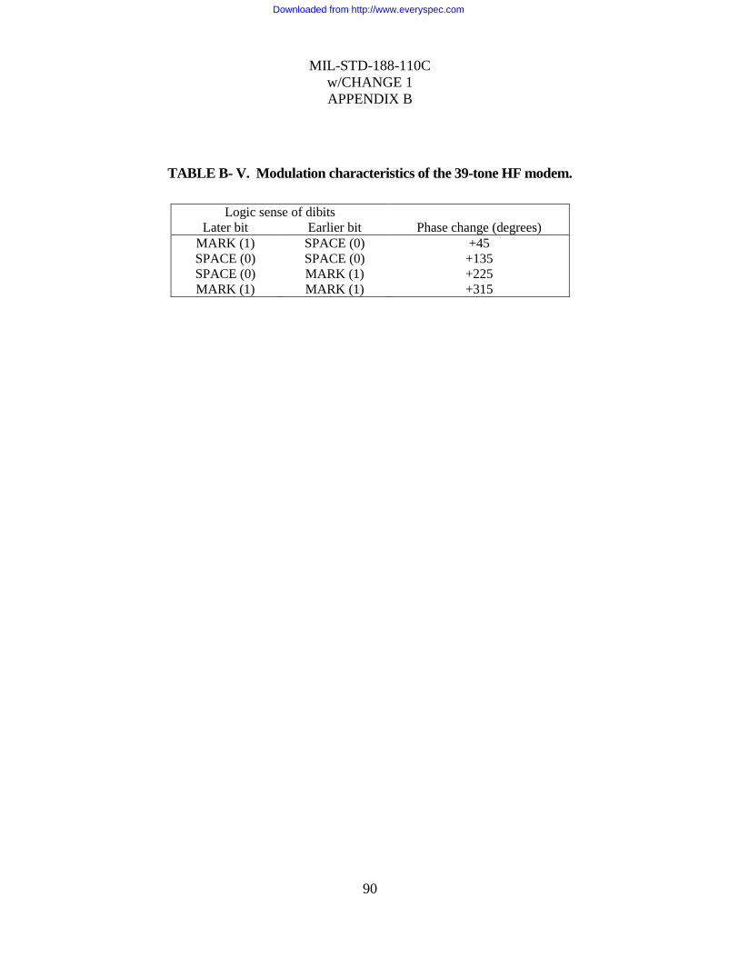
MIL-STD-188-110C
w/CHANGE 1
APPENDIX B
90
TABLE B- V. Modulation characteristics of the 39-tone HF modem.
Logic sense of dibits
Later bit Earlier bit Phase change (degrees)
MARK (1) SPACE (0) +45
SPACE (0) SPACE (0) +135
SPACE (0) MARK (1) +225
MARK (1) MARK (1) +315
Downloaded from http://www.everyspec.com

MIL-STD-188-110C
w/CHANGE 1
APPENDIX B
91
TABLE B- VI. In-band time/frequency diversity.
Tone
number
600 bps Data
word
300 bps Data
word
150 bps Data
word
75 bps Data
word
1 1 2
i
1 2
i
1 2
i
1 2 i
2 3 4 3 4 3 4 3 4
3 5 6 5 6 5 6 1 2 i-1
4 7 8 7 8 7 8 3 4
5 9 10 9 10 1 2
i-2
1 2 i-2
6 11 12 11 12 3 4 3 4
7 13 14 13 14 5 6 1 2 i-3
8 15 16 15 16 7 8 3 4
9 17 18 1 2
i-4
1 2
i-4
1 2 i-4
10 19 20 3 4 3 4 3 4
11 21 22 5 6 5 6 1 2 i-5
12 23 24 7 8 7 8 3 4
13 25 26 9 10 1 2
i-6
1 2 i-6
14 27 28 11 12 3 4 3 4
15 29 30 13 14 5 6 1 2 i-7
16 31 32 15 16 7 8 3 4
17 1 2
i-8
1 2
i-8
1 2
i-8
1 2 i-8
18 3 4 3 4 3 4 3 4
19 5 6 5 6 5 6 1 2 i-9
20 7 8 7 8 7 8 3 4
21 9 10 9 10 1 2
i-10
1 2 i-10
22 11 12 11 12 3 4 3 4
23 13 14 13 14 5 6 1 2 i-11
24 15 16 15 16 7 8 3 4
25 17 18 1 2
i-12
1 2
i-12
1 2 i-12
26 19 20 3 4 3 4 3 4
27 21 22 5 6 5 6 1 2 i-13
28 23 24 7 8 7 8 3 4
29 25 26 9 10 1 2
i-14
1 2 i-14
30 27 28 11 12 3 4 3 4
31 29 30 13 14 5 6 1 2 i-15
32 31 32 15 16 7 8 3 4
33 1 2
i
1 2
i
1 2
i
1 2 i
34 3 4 3 4 3 4 3 4
35 5 6 5 6 5 6 1 2 i-1
36 7 8 7 8 7 8 3 4
37 9 10 9 10 1 2 i-2
1 2 i-2
38 11 12 11 12 3 4 3 4
39 13 14 13 14 5 6 1 2 i-3
Downloaded from http://www.everyspec.com
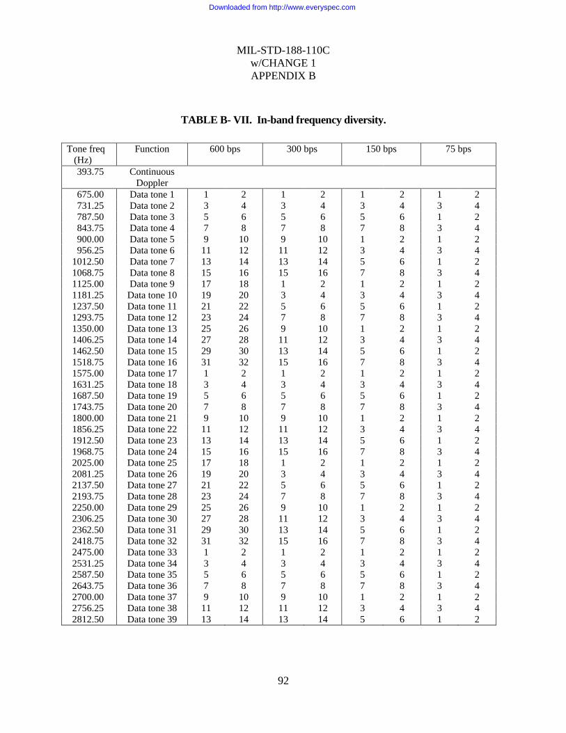
MIL-STD-188-110C
w/CHANGE 1
APPENDIX B
92
TABLE B- VII. In-band frequency diversity.
Tone freq
(Hz)
Function 600 bps 300 bps 150 bps 75 bps
393.75 Continuous
Doppler
675.00 Data tone 1 1 2 1 2 1 2 1 2
731.25 Data tone 2 3 4 3 4 3 4 3 4
787.50 Data tone 3 5 6 5 6 5 6 1 2
843.75 Data tone 4 7 8 7 8 7 8 3 4
900.00 Data tone 5 9 10 9 10 1 2 1 2
956.25 Data tone 6 11 12 11 12 3 4 3 4
1012.50 Data tone 7 13 14 13 14 5 6 1 2
1068.75 Data tone 8 15 16 15 16 7 8 3 4
1125.00 Data tone 9 17 18 1 2 1 2 1 2
1181.25 Data tone 10 19 20 3 4 3 4 3 4
1237.50 Data tone 11 21 22 5 6 5 6 1 2
1293.75 Data tone 12 23 24 7 8 7 8 3 4
1350.00 Data tone 13 25 26 9 10 1 2 1 2
1406.25 Data tone 14 27 28 11 12 3 4 3 4
1462.50 Data tone 15 29 30 13 14 5 6 1 2
1518.75 Data tone 16 31 32 15 16 7 8 3 4
1575.00 Data tone 17 1 2 1 2 1 2 1 2
1631.25 Data tone 18 3 4 3 4 3 4 3 4
1687.50 Data tone 19 5 6 5 6 5 6 1 2
1743.75 Data tone 20 7 8 7 8 7 8 3 4
1800.00 Data tone 21 9 10 9 10 1 2 1 2
1856.25 Data tone 22 11 12 11 12 3 4 3 4
1912.50 Data tone 23 13 14 13 14 5 6 1 2
1968.75 Data tone 24 15 16 15 16 7 8 3 4
2025.00 Data tone 25 17 18 1 2 1 2 1 2
2081.25 Data tone 26 19 20 3 4 3 4 3 4
2137.50 Data tone 27 21 22 5 6 5 6 1 2
2193.75 Data tone 28 23 24 7 8 7 8 3 4
2250.00 Data tone 29 25 26 9 10 1 2 1 2
2306.25 Data tone 30 27 28 11 12 3 4 3 4
2362.50 Data tone 31 29 30 13 14 5 6 1 2
2418.75 Data tone 32 31 32 15 16 7 8 3 4
2475.00 Data tone 33 1 2 1 2 1 2 1 2
2531.25 Data tone 34 3 4 3 4 3 4 3 4
2587.50 Data tone 35 5 6 5 6 5 6 1 2
2643.75 Data tone 36 7 8 7 8 7 8 3 4
2700.00 Data tone 37 9 10 9 10 1 2 1 2
2756.25 Data tone 38 11 12 11 12 3 4 3 4
2812.50 Data tone 39 13 14 13 14 5 6 1 2
Downloaded from http://www.everyspec.com

MIL-STD-188-110C
w/CHANGE 1
APPENDIX B
93
TABLE B- VIII. Asynchronous character set.
Character bit designation and location
Number of
bits
1 2 3 4 5 6 7 8 9 10 11 12
7 St Da Da Da Da Da Sp
8 St Da Da Da Da Da P+ Sp
8 St Da Da Da Da Da P- Sp
8 St Da Da Da Da Da Sp Sp
8 St Da Da Da Da Da Da Sp
9 St Da Da Da Da Da P+ Sp Sp
9 St Da Da Da Da Da P- Sp Sp
9 St Da Da Da Da Da Da P+ Sp
9 St Da Da Da Da Da Da P- Sp
9 St Da Da Da Da Da Da Sp Sp
9 St Da Da Da DA Da Da Da Sp
l0 St Da Da Da Da Da Da P+ Sp Sp
10 St Da Da Da Da Da Da P- Sp Sp
10 St Da Da Da Da Da Da Da P+ Sp
10 St Da Da Da Da Da Da Da P- Sp
10 St Da Da Da Da Da Da Da Sp Sp
10 St Da Da Da Da Da Da Da Da Sp
11 St Da Da Da Da Da Da Da P+ Sp Sp
11 St Da Da Da Da Da Da Da P- Sp Sp
11 St Da Da Da Da Da Da Da Da P+ Sp
11 St Da Da Da Da Da Da Da Da P- Sp
11 St Da Da Da Da Da Da Da Da Sp Sp
12 St Da Da Da Da Da Da Da Da P+ Sp Sp
12 St Da Da Da Da Da Da Da Da P- Sp Sp
Bit labeling key: Da = Data St = Start P+ = Positive parity
Sp = Stop P- = Negative parity
Downloaded from http://www.everyspec.com

MIL-STD-188-110C
w/CHANGE 1
APPENDIX B
94
TABLE B- IX. 75 bps and 150 bps asynchronous operational parameters.
Data
rate
(bps)
Char
length
(bits)
Intlv
degree
Super
blocks
Number of
bits encoded
Number
of source
bits
fill
bits
Seq
Number
length (bits)
75 7 1 567 6804 6804 0 252
75 7 5 189 11340 11340 0 420
75 7 12 84 12096 12096 0 448
75 7 35 18 7560 7560 0 280
75 8 1 576 6912 6912 0 256
75 8 4 234 11232 11232 0 416
75 8 12 75 10800 10800 0 400
75 8 36 16 6912 6912 0 256
75 9 1 567 6804 6804 0 252
75 9 4 252 12096 12096 0 448
75 9 12 84 12096 12096 0 448
75 9 36 16 6912 6912 0 256
75 10 1 585 7020 7020 0 260
75 10 4 242 11616 11610 6 416
75 10 12 75 10800 10800 0 400
75 10 35 18 7560 7560 0 280
75 11 1 594 7128 7128 0 264
75 11 4 260 12480 12474 6 448
75 11 11 99 13068 13068 0 484
75 11 33 18 7128 7128 0 264
75 12 1 567 6804 6804 0 252
75 12 4 261 12528 12528 0 464
75 12 12 84 12096 12096 0 448
75 12 36 16 6912 6912 0 256
150 7 1 567 6804 6804 0 252
150 7 9 112 12096 12096 0 448
150 7 27 35 11340 11340 0 420
150 7 81 7 6804 6804 0 252
150 8 1 576 6912 6912 0 256
Downloaded from http://www.everyspec.com

MIL-STD-188-110C
w/CHANGE 1
APPENDIX B
95
Data
rate
(bps)
Char
length
(bits)
Intlv
degree
Super
blocks
Number of
bits encoded
Number
of source
bits
fill
bits
Seq
Number
length (bits)
150 8 9 100 10800 10800 0 400
150 8 25 36 10800 10800 0 400
150 8 81 8 7776 7776 0 288
150 9 1 567 6804 6804 0 252
150 9 9 112 12096 12096 0 448
150 9 25 38 11400 11394 6 408
150 9 81 7 6804 6804 0 252
150 10 1 585 7020 7020 0 260
150 10 9 110 11880 11880 0 440
150 10 25 36 10800 10800 0 400
150 10 75 9 8100 8100 0 300
150 11 1 594 7128 7128 0 264
150 11 9 110 11880 11880 0 440
150 11 27 33 10692 10692 0 396
150 11 77 9 8316 8316 0 308
150 12 1 567 6804 6804 0 252
150 12 9 110 11880 11880 0 440
150 12 27 33 10692 10692 0 396
150 12 81 7 6804 6804 0 252
Downloaded from http://www.everyspec.com

MIL-STD-188-110C
w/CHANGE 1
APPENDIX B
96
TABLE B- X. 300 bps and 600 bps asynchronous operational parameters.
Data rate
(bps)
Char length
(bits)
Intlv
degree
Super
blocks
Number of
bits encoded
Number
of source
bits
fill
bits
Seq Number
length (bits)
300 7 1 567 6804 6804 0 252
300 7 15 63 11340 11340 0 420
300 7 49 18 10584 10584 0 392
300 7 145 5 8700 8694 6 308
300 8 1 576 6912 6912 0 256
300 8 17 54 11016 11016 0 408
300 8 47 18 10152 10152 0 376
300 8 153 4 7344 7344 0 272
300 9 1 567 6804 6804 0 252
300 9 17 54 ll016 11016 0 408
300 9 47 18 10152 10152 0 376
300 9 153 4 7344 7344 0 272
300 10 1 585 7020 7020 0 260
300 10 17 49 9996 9990 6 356
300 10 45 22 11880 11880 0 440
300 10 153 5 9180 9180 0 340
300 11 1 594 7128 7128 0 264
300 11 19 43 9804 9801 3 356
300 11 45 22 11880 11880 0 440
300 11 161 4 7728 7722 6 272
300 12 1 567 6804 6804 0 252
300 12 17 54 11016 11016 0 408
300 12 49 18 10584 10584 0 392
300 12 153 4 7344 7344 0 272
600 7 1 567 6804 6804 0 252
600 7 35 27 11340 11340 0 420
600 7 105 9 11340 11340 0 420
600 7 315 2 7560 7560 0 280
600 8 1 576 6912 6912 0 256
Downloaded from http://www.everyspec.com
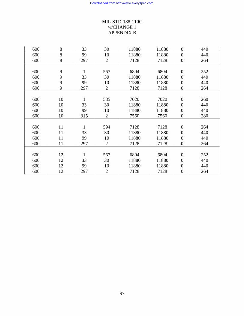
MIL-STD-188-110C
w/CHANGE 1
APPENDIX B
97
600 8 33 30 11880 11880 0 440
600 8 99 10 11880 11880 0 440
600 8 297 2 7128 7128 0 264
600 9 1 567 6804 6804 0 252
600 9 33 30 11880 11880 0 440
600 9 99 10 11880 11880 0 440
600 9 297 2 7128 7128 0 264
600 10 1 585 7020 7020 0 260
600 10 33 30 11880 11880 0 440
600 10 99 10 11880 11880 0 440
600 10 315 2 7560 7560 0 280
600 11 1 594 7128 7128 0 264
600 11 33 30 11880 11880 0 440
600 11 99 10 11880 11880 0 440
600 11 297 2 7128 7128 0 264
600 12 1 567 6804 6804 0 252
600 12 33 30 11880 11880 0 440
600 12 99 10 11880 11880 0 440
600 12 297 2 7128 7128 0 264
Downloaded from http://www.everyspec.com
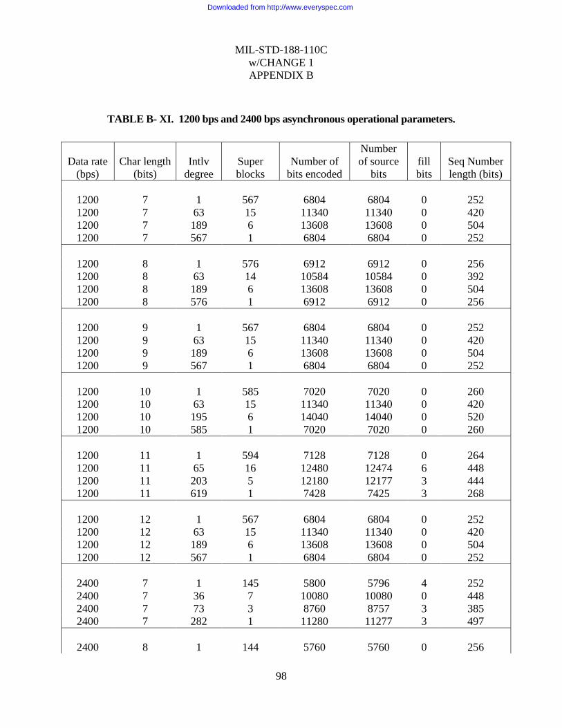
MIL-STD-188-110C
w/CHANGE 1
APPENDIX B
98
TABLE B- XI. 1200 bps and 2400 bps asynchronous operational parameters.
Data rate
(bps)
Char length
(bits)
Intlv
degree
Super
blocks
Number of
bits encoded
Number
of source
bits
fill
bits
Seq Number
length (bits)
1200 7 1 567 6804 6804 0 252
1200 7 63 15 11340 11340 0 420
1200 7 189 6 13608 13608 0 504
1200 7 567 1 6804 6804 0 252
1200 8 1 576 6912 6912 0 256
1200 8 63 14 10584 10584 0 392
1200 8 189 6 13608 13608 0 504
1200 8 576 1 6912 6912 0 256
1200 9 1 567 6804 6804 0 252
1200 9 63 15 11340 11340 0 420
1200 9 189 6 13608 13608 0 504
1200 9 567 1 6804 6804 0 252
1200 10 1 585 7020 7020 0 260
1200 10 63 15 11340 11340 0 420
1200 10 195 6 14040 14040 0 520
1200 10 585 1 7020 7020 0 260
1200 11 1 594 7128 7128 0 264
1200 11 65 16 12480 12474 6 448
1200 11 203 5 12180 12177 3 444
1200 11 619 1 7428 7425 3 268
1200 12 1 567 6804 6804 0 252
1200 12 63 15 11340 11340 0 420
1200 12 189 6 13608 13608 0 504
1200 12 567 1 6804 6804 0 252
2400 7 1 145 5800 5796 4 252
2400 7 36 7 10080 10080 0 448
2400 7 73 3 8760 8757 3 385
2400 7 282 1 11280 11277 3 497
2400 8 1 144 5760 5760 0 256
Downloaded from http://www.everyspec.com

MIL-STD-188-110C
w/CHANGE 1
APPENDIX B
99
Data rate
(bps)
Char length
(bits)
Intlv
degree
Super
blocks
Number of
bits encoded
Number
of source
bits
fill
bits
Seq Number
length (bits)
2400 8 36 7 10080 10080 0 448
2400 8 72 3 8640 8640 0 384
2400 8 288 1 11520 11520 0 512
2400 9 1 144 5760 5760 0 256
2400 9 36 7 10080 10080 0 448
2400 9 72 3 8640 8640 0 384
2400 9 288 1 11520 11520 0 512
2400 10 1 144 5760 5760 0 256
2400 10 36 7 10080 10080 0 448
2400 10 72 3 8640 8640 0 384
2400 10 288 1 11520 11520 0 512
2400 11 1 151 6040 6039 1 267
2400 11 33 9 11880 11880 0 528
2400 11 71 3 8520 8514 6 370
2400 11 297 1 11880 11880 0 528
2400 12 1 144 5760 5760 0 256
2400 12 36 7 10080 10080 0 448
2400 12 72 3 8640 8640 0 384
2400 12 288 1 11520 11520 0 512
Downloaded from http://www.everyspec.com

MIL-STD-188-110C
w/CHANGE 1
APPENDIX B
100
TABLE B- XII. Probability of bit error vs signal-to-noise ratio.
Signal-to-noise ratio
(dB in 3-kHz
bandwidth)
Probability of bit error
2400 bps 1200 bps
5 - 6.4 E-2
11 3.5 E-2 4.4 E-3
16 1.0 E-2 3.4E-4
21 1.0 E-3 9.0 E-6
31 1.8 E-4 2.7 E-6
Probability of bit error
300 bps 75 bps
1 1.8 E-2 4.4 E-4
3 6.4 E-3 5.0 E-5
5 1.0 E-3 1.0 E-6
7 5.0 E-5 1.0 E-6
9 1.5 E-6 1.0 E-6
NOTE: Two independent equal average power Rayleigh fading paths, with 2 Hz fading
bandwidth and 2 ms multipath spread, using a simulator in accordance with Appendix E.
Downloaded from http://www.everyspec.com

MIL-STD-188-110C
w/CHANGE 1
APPENDIX B
101
FEC CODING
INTERLEAVE MATRIX #1
INTERLEAVE MATRIX #2
DATA FETCH
BLOCK SYNC
PREAMBLE SYNC
TONE MODULATOR
(2400)
UNKNOWN DATA
FILL OR EOM SEQUENCE
(3360)
(107)
PREAMBLE CONTROL
}
COMPOSITE
39-TONE + DOPPLER
SIGNAL
.
FIGURE B- 2. Transmit direction functional diagram.
Downloaded from http://www.everyspec.com

MIL-STD-188-110C
w/CHANGE 1
APPENDIX B
102
CODEWORD 1
CODEWORD 4 CODEWORD 3 CODEWORD 2 CODEWORD 1
D47 D46 D45 D44 … D4 D3 D2 D1 D0 P3 P2 P1 P0 D19 D18 D17 D16
D11 D10 D9 D8 D3 D2 D1 D0
INPUT DATA STREAM
FEC
ENCODER
FIRST
BIT IN FIRST
BIT OUT
INTERLEAVER P63 P62 … P12 … D16 D39 … D8 D31 D30 D29 D28 D27 D26
D25 D24 D7 D6 D5 D4 D3 D2 D1 D0
D31 D30 D29 D28 D27 D26 D25 D24 D7 D6 D5 D4 D3 D2 D1 D0 SYMBOL 0
D39 D38 D37 D36 D35 D34 D33 D32 D15 D14 D13 D12 D11 D10 D9 D8 SYMBOL 1
D47 D46 D45 D44 D43 D42 D41 D40 D23 D22 D21 D20 D19 D18 D17 D16 SYMBOL 2
P51 P50 P49 P48 P35 P34 P33 P32 P19 P18 P17 P16 P3 P2 P1 P0 SYMBOL 3
P55 P54 P53 P52 P39 P38 P37 P36 P23 P22 P21 P20 P7 P6 P5 P4 SYMBOL 4
P59 P58 P57 P56 P43 P42 P41 P40 P27 P26 P25 P24 P11 P10 P9 P8 SYMBOL 5
P63 P62 P61 P60 P47 P46 P45 P44 P31 P30 P29 P28 P15 P14 P13 P12 SYMBOL 6
DATA
SYMBOLS
PARITY
SYMBOLS
FIGURE B- 3. Data flow through encoder and interleaver for an interleaver containing an even
number of code words.
Downloaded from http://www.everyspec.com

MIL-STD-188-110C
w/CHANGE 1
APPENDIX B
103
CODEWORD 1
CODEWORD 3 CODEWORD 2 CODEWORD 1
D35 D34 D33 D32 … D4 D3 D2 D1 D0 P3 P2 P1 P0 D19 D18 D17 D16
D11 D10 D9 D8 D3 D2 D1 D0
INPUT DATA STREAM
FEC
ENCODER
FIRST
BIT IN FIRST
BIT OUT
INTERLEAVER P47 P46 … P13 P12 … D16 D31 … D12 D11 D10 D9 D8 D27 D26
D25 D24 D7 D6 D5 D4 D3 D2 D1 D0
. .
D27 D26 D25 D24 D7 D6 D5 D4 D3 D2 D1 D0 SYMBOL 0
D31 D30 D29 D28 D15 D14 D13 D12 D11 D10 D9 D8 SYMBOL 1
D35 D34 D33 D32 D23 D22 D21 D20 D19 D18 D17 D16 SYMBOL 2
P35 P34 P33 P32 P19 P18 P17 P16 P3 P2 P1 P0 SYMBOL 3
P39 P38 P37 P36 P23 P22 P21 P20 P7 P6 P5 P4 SYMBOL 4
P43 P42 P41 P40 P27 P26 P25 P24 P11 P10 P9 P8 SYMBOL 5
P47 P46 P45 P44 P31 P30 P29 P28 P15 P14 P13 P12 SYMBOL 6
DATA
SYMBOLS
PARITY
SYMBOLS
FIGURE B- 4. Data flow through encoder and interleaver for an interleaver containing an odd
number of code words.
Downloaded from http://www.everyspec.com
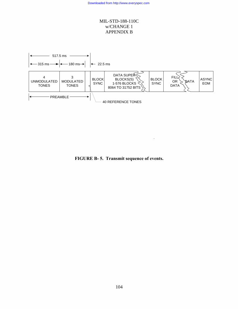
MIL-STD-188-110C
w/CHANGE 1
APPENDIX B
104
3
MODULATED
TONES
BLOCK
SYNC
4
UNMODULATED
TONES
DATA SUPER
BLOCKS(S)
1-576 BLOCKS
8064 TO 31752 BITS
BLOCK
SYNC
FILL
OR
DATA
DATA ASYNC
EOM
315 ms 180 ms 22.5 ms
517.5 ms
PREAMBLE
40 REFERENCE TONES
.
FIGURE B- 5. Transmit sequence of events.
Downloaded from http://www.everyspec.com

MIL-STD-188-110C
w/CHANGE 1
APPENDIX B
105
FIGURE B- 6. Framing sequence feedback shift register generator
Downloaded from http://www.everyspec.com
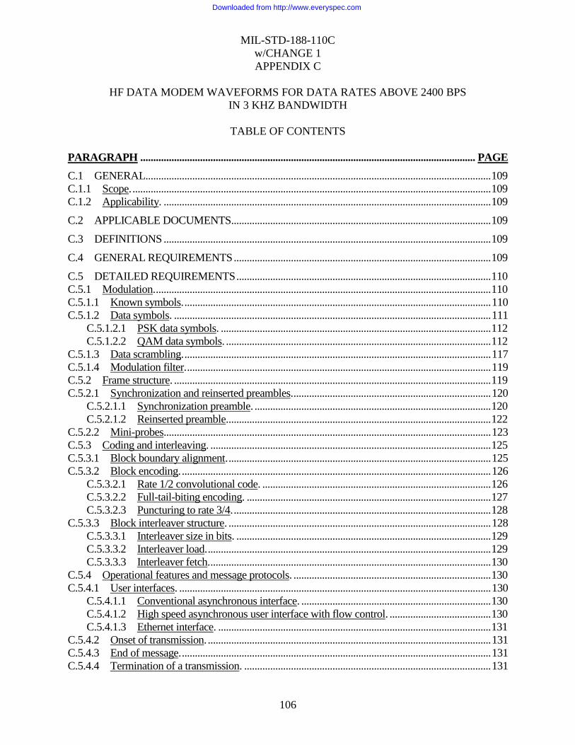
MIL-STD-188-110C
w/CHANGE 1
APPENDIX C
106
HF DATA MODEM WAVEFORMS FOR DATA RATES ABOVE 2400 BPS
IN 3 KHZ BANDWIDTH
TABLE OF CONTENTS
PARAGRAPH ................................................................................................................................. PAGE
C.1 GENERAL ..................................................................................................................................... 109
C.1.1 Scope. .......................................................................................................................................... 109
C.1.2 Applicability. .............................................................................................................................. 109
C.2 APPLICABLE DOCUMENTS.................................................................................................... 109
C.3 DEFINITIONS .............................................................................................................................. 109
C.4 GENERAL REQUIREMENTS ................................................................................................... 109
C.5 DETAILED REQUIREMENTS .................................................................................................. 110
C.5.1 Modulation. ................................................................................................................................. 110
C.5.1.1 Known symbols. ...................................................................................................................... 110
C.5.1.2 Data symbols. .......................................................................................................................... 111
C.5.1.2.1 PSK data symbols. ........................................................................................................ 112
C.5.1.2.2 QAM data symbols. ...................................................................................................... 112
C.5.1.3 Data scrambling. ...................................................................................................................... 117
C.5.1.4 Modulation filter. ..................................................................................................................... 119
C.5.2 Frame structure. .......................................................................................................................... 119
C.5.2.1 Synchronization and reinserted preambles. ............................................................................ 120
C.5.2.1.1 Synchronization preamble. ........................................................................................... 120
C.5.2.1.2 Reinserted preamble. ..................................................................................................... 122
C.5.2.2 Mini-probes. ............................................................................................................................. 123
C.5.3 Coding and interleaving. ............................................................................................................ 125
C.5.3.1 Block boundary alignment. ..................................................................................................... 125
C.5.3.2 Block encoding. ....................................................................................................................... 126
C.5.3.2.1 Rate 1/2 convolutional code. ........................................................................................ 126
C.5.3.2.2 Full-tail-biting encoding. .............................................................................................. 127
C.5.3.2.3 Puncturing to rate 3/4. ................................................................................................... 128
C.5.3.3 Block interleaver structure. ..................................................................................................... 128
C.5.3.3.1 Interleaver size in bits. .................................................................................................. 129
C.5.3.3.2 Interleaver load. ............................................................................................................. 129
C.5.3.3.3 Interleaver fetch. ............................................................................................................ 130
C.5.4 Operational features and message protocols. ............................................................................ 130
C.5.4.1 User interfaces. ........................................................................................................................ 130
C.5.4.1.1 Conventional asynchronous interface. ......................................................................... 130
C.5.4.1.2 High speed asynchronous user interface with flow control. ....................................... 130
C.5.4.1.3 Ethernet interface. ......................................................................................................... 131
C.5.4.2 Onset of transmission. ............................................................................................................. 131
C.5.4.3 End of message. ....................................................................................................................... 131
C.5.4.4 Termination of a transmission. ............................................................................................... 131
Downloaded from http://www.everyspec.com
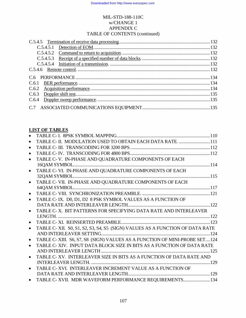
MIL-STD-188-110C
w/CHANGE 1
APPENDIX C
107
TABLE OF CONTENTS (continued)
C.5.4.5 Termination of receive data processing. ................................................................................. 132
C.5.4.5.1 Detection of EOM. ........................................................................................................ 132
C.5.4.5.2 Command to return to acquisition. ............................................................................... 132
C.5.4.5.3 Receipt of a specified number of data blocks. ............................................................. 132
C.5.4.5.4 Initiation of a transmission. .......................................................................................... 132
C.5.4.6 Remote control. ....................................................................................................................... 132
C.6 PERFORMANCE ......................................................................................................................... 134
C.6.1 BER performance. ...................................................................................................................... 134
C.6.2 Acquisition performance. ........................................................................................................... 134
C.6.3 Doppler shift test. ........................................................................................................................ 135
C.6.4 Doppler sweep performance. ..................................................................................................... 135
C.7 ASSOCIATED COMMUNICATIONS EQUIPMENT ............................................................. 135
LIST OF TABLES
TABLE C- I. 8PSK SYMBOL MAPPING. ................................................................................... 110
TABLE C- II. MODULATION USED TO OBTAIN EACH DATA RATE. ............................ 111
TABLE C- III. TRANSCODING FOR 3200 BPS. ....................................................................... 112
TABLE C- IV. TRANSCODING FOR 4800 BPS. ....................................................................... 112
TABLE C- V. IN-PHASE AND QUADRATURE COMPONENTS OF EACH
16QAM SYMBOL. .......................................................................................................................... 114
TABLE C- VI. IN-PHASE AND QUADRATURE COMPONENTS OF EACH
32QAM SYMBOL. .......................................................................................................................... 115
TABLE C- VII. IN-PHASE AND QUADRATURE COMPONENTS OF EACH
64QAM SYMBOL. .......................................................................................................................... 117
TABLE C- VIII. SYNCHRONIZATION PREAMBLE. ............................................................. 121
TABLE C- IX. D0, D1, D2 8 PSK SYMBOL VALUES AS A FUNCTION OF
DATA RATE AND INTERLEAVER LENGTH.......................................................................... 122
TABLE C- X. BIT PATTERNS FOR SPECIFYING DATA RATE AND INTERLEAVER
LENGTH. ......................................................................................................................................... 122
TABLE C- XI. REINSERTED PREAMBLE. ............................................................................... 123
TABLE C- XII. S0, S1, S2, S3, S4, S5 (SIGN) VALUES AS A FUNCTION OF DATA RATE
AND INTERLEAVER SETTING. ................................................................................................. 124
TABLE C- XIII. S6, S7, S8 (SIGN) VALUES AS A FUNCTION OF MINI-PROBE SET. ... 124
TABLE C- XIV. INPUT DATA BLOCK SIZE IN BITS AS A FUNCTION OF DATA RATE
AND INTERLEAVER LENGTH .................................................................................................. 125
TABLE C- XV. INTERLEAVER SIZE IN BITS AS A FUNCTION OF DATA RATE AND
INTERLEAVER LENGTH. ........................................................................................................... 129
TABLE C- XVI. INTERLEAVER INCREMENT VALUE AS A FUNCTION OF
DATA RATE AND INTERLEAVER LENGTH.......................................................................... 129
TABLE C- XVII. MDR WAVEFORM PERFORMANCE REQUIREMENTS. ....................... 134
Downloaded from http://www.everyspec.com

MIL-STD-188-110C
w/CHANGE 1
APPENDIX C
108
LIST OF FIGURES
FIGURE C- 1. 8PSK SIGNAL CONSTELLATION AND SYMBOL MAPPING. .................. 111
FIGURE C- 2. 16QAM SIGNALING CONSTELLATION. ....................................................... 113
FIGURE C- 3. 32QAM SIGNALING CONSTELLATION. ....................................................... 114
FIGURE C- 4. 64QAM SIGNALING CONSTELLATION. ....................................................... 116
FIGURE C- 5. SCRAMBLING SEQUENCE GENERATOR ILLUSTRATING
SCRAMBLING GENERATOR FOR 8PSK SYMBOLS. ........................................................... 118
FIGURE C- 6. FRAME STRUCTURE FOR ALL WAVEFORMS. .......................................... 120
FIGURE C- 7. CONSTRAINT LENGTH 7, RATE 1/2 CONVOLUTIONAL ENCODER. .... 127
Downloaded from http://www.everyspec.com

MIL-STD-188-110C
w/CHANGE 1
APPENDIX C
109
C.1 SCOPE
C.1.1 Scope.
This appendix describes HF data modem waveforms for data rates above 2400 bps in 3 kHz
channels. These may be termed narrowband, medium data rate (MDR) waveforms.
C.1.2 Applicability.
This appendix is a non-mandatory part of MIL-STD-188-110B; however, when using HF data
modem waveforms for data rates above 2400 bps in 3 kHz channels, they shall be implemented
in accordance with this appendix.
C.2 APPLICABLE DOCUMENTS
This section is not applicable to this appendix.
C.3 DEFINITIONS
See section 3.
C.4 GENERAL REQUIREMENTS
This appendix presents a modem waveform and coding specification for data rates of 3200,
4800, 6400, 8000 and 9600 bps. Uncoded operation at 12800 bps is a DO. The single-tone
waveforms specified in this appendix use modulation techniques of greater complexity and data
blocks larger than those found in section 5.3.2 of this standard in order to achieve the efficiencies
necessary to obtain the required data rates. A block interleaver is used to obtain 6 interleaving
lengths ranging from 0.12 s to 8.64 s. A single coding option, a constraint length 7, rate 1/2
convolutional code, punctured to rate 3/4, is used for all data rates. The full-tail-biting approach
is used to produce block codes from this convolutional code that are the same length as the
interleaver. Since the minimum interleaver length spans a single data frame, there is no option of
zero interleaving, since the time delays would not be reduced.
Both the data rate and interleaver settings are explicitly transmitted as a part of the waveform,
both as part of the initial preamble and then periodically as both a reinserted preamble and in the
periodic known symbol blocks. This “autobaud” feature is critical in developing an efficient
(ARQ) protocol for high frequency (HF) channels. The receive modem is required to be able to
deduce the data rate and interleaver setting both from the preamble or from the subsequent data
portion of the waveform.
Downloaded from http://www.everyspec.com
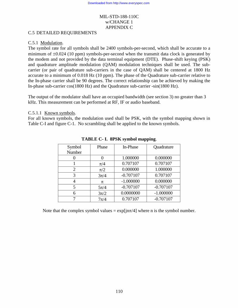
MIL-STD-188-110C
w/CHANGE 1
APPENDIX C
110
C.5 DETAILED REQUIREMENTS
C.5.1 Modulation.
The symbol rate for all symbols shall be 2400 symbols-per-second, which shall be accurate to a
minimum of 0.024 (10 ppm) symbols-per-second when the transmit data clock is generated by
the modem and not provided by the data terminal equipment (DTE). Phase-shift keying (PSK)
and quadrature amplitude modulation (QAM) modulation techniques shall be used. The sub-
carrier (or pair of quadrature sub-carriers in the case of QAM) shall be centered at 1800 Hz
accurate to a minimum of 0.018 Hz (10 ppm). The phase of the Quadrature sub-carrier relative to
the In-phase carrier shall be 90 degrees. The correct relationship can be achieved by making the
In-phase sub-carrier cos(1800 Hz) and the Quadrature sub-carrier -sin(1800 Hz).
The output of the modulator shall have an occupied bandwidth (see section 3) no greater than 3
kHz. This measurement can be performed at RF, IF or audio baseband.
C.5.1.1 Known symbols.
For all known symbols, the modulation used shall be PSK, with the symbol mapping shown in
Table C-I and figure C-1. No scrambling shall be applied to the known symbols.
TABLE C- I. 8PSK symbol mapping.
Symbol
Number
Phase In-Phase Quadrature
0 0 1.000000 0.000000
1 /4 0.707107 0.707107
2 /2 0.000000 1.000000
3 3/4 -0.707107 0.707107
4 -1.000000 0.000000
5 5/4 -0.707107 -0.707107
6 3/2 0.0000000 -1.000000
7 7/4 0.707107 -0.707107
Note that the complex symbol values = exp[jn/4] where n is the symbol number.
Downloaded from http://www.everyspec.com

MIL-STD-188-110C
w/CHANGE 1
APPENDIX C
111
Symbol 0
Symbol 1
Symbol 2
Symbol 3
Symbol 4
Symbol 5
Symbol 6
Symbol 7
FIGURE C- 1. 8PSK signal constellation and symbol mapping.
C.5.1.2 Data symbols.
For data symbols, the modulation used shall depend upon the data rate. Table C-II specifies the
modulation that shall be used with each data rate.
TABLE C- II. Modulation used to obtain each data rate.
Data Rate
(bps)
Modulation
3200 QPSK
4800 8PSK
6400 16QAM
8000 32QAM
9600 64QAM
12800 64QAM
The 3200 bps quadrature phase-shift keying (QPSK) constellation is scrambled to appear, on-air,
as an 8PSK constellation. Both the 16QAM and 32QAM constellations use multiple PSK rings
to maintain good peak-to-average ratios, and the 64QAM constellation is a variation of the
standard square QAM constellation, which has been modified to improve the peak-to-average
ratio.
Downloaded from http://www.everyspec.com

MIL-STD-188-110C
w/CHANGE 1
APPENDIX C
112
C.5.1.2.1 PSK data symbols.
For the PSK constellations, a distinction is made between the data bits and the symbol number
for the purposes of scrambling the QPSK modulation to appear as 8PSK, on-air. Scrambling is
applied as a modulo 8 addition of a scrambling sequence to the 8PSK symbol number.
Transcoding is an operation which links a symbol to be transmitted to a group of data bits.
C.5.1.2.1.1 QPSK symbol mapping.
For the 3200 bps user data rate, transcoding shall be achieved by linking one of the symbols
specified in Table C-I to a set of two consecutive data bits (dibit) as shown in Table C-III. In this
Table, the leftmost bit of the dibit shall be the older bit; i.e., fetched from the interleaver before
the rightmost bit.
TABLE C- III. Transcoding for 3200 bps.
Dibit Symbol
00 0
01 2
11 4
10 6
C.5.1.2.1.2 8PSK symbol mapping.
For the 4800 bps user data rate, transcoding shall be achieved by linking one symbol to a set of
three consecutive data bits (tribit) as shown in Table C-IV. In this Table, the leftmost bit of the
tribit shall be the oldest bit; i.e., fetched from the interleaver before the other two, and the
rightmost bit is the most recent bit.
TABLE C- IV. Transcoding for 4800 bps.
Tribit Symbol
000 1
001 0
010 2
011 3
100 6
101 7
110 5
111 4
C.5.1.2.2 QAM data symbols.
For the QAM constellations, no distinction is made between the number formed directly from the
data bits and the symbol number. Each set of 4 bits (16QAM), 5 bits (32QAM) or 6 bits
(64QAM) is mapped directly to a QAM symbol. For example, the four bit grouping 0111 would
map to symbol 7 in the 16QAM constellation while the 6 bits 100011 would map to symbol 35 in
the 64QAM constellation. Again, in each case the leftmost bit shall be the oldest bit, i.e. fetched
from the interleaver before the other bits, and the rightmost bit is the most recent bit. The
Downloaded from http://www.everyspec.com
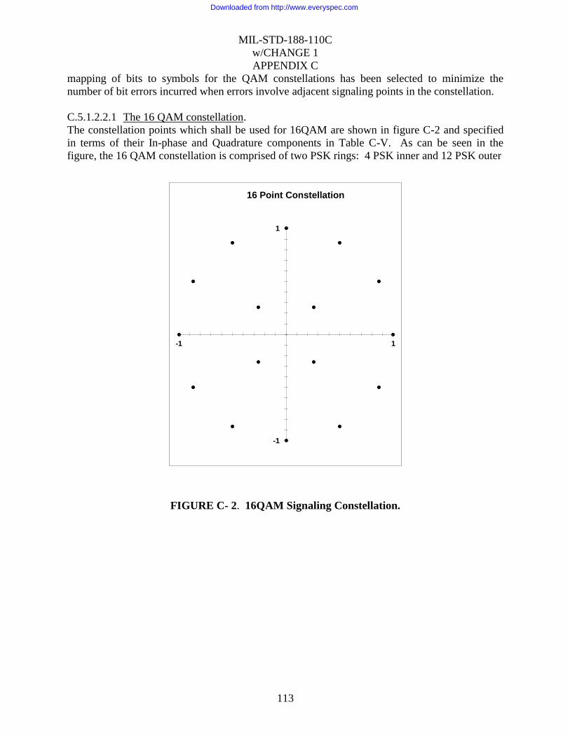
MIL-STD-188-110C
w/CHANGE 1
APPENDIX C
113
mapping of bits to symbols for the QAM constellations has been selected to minimize the
number of bit errors incurred when errors involve adjacent signaling points in the constellation.
C.5.1.2.2.1 The 16 QAM constellation.
The constellation points which shall be used for 16QAM are shown in figure C-2 and specified
in terms of their In-phase and Quadrature components in Table C-V. As can be seen in the
figure, the 16 QAM constellation is comprised of two PSK rings: 4 PSK inner and 12 PSK outer
-1
1
-1 1
16 Point Constellation
FIGURE C- 2. 16QAM Signaling Constellation.
Downloaded from http://www.everyspec.com
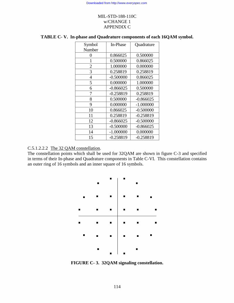
MIL-STD-188-110C
w/CHANGE 1
APPENDIX C
114
TABLE C- V. In-phase and Quadrature components of each 16QAM symbol.
Symbol
Number
In-Phase Quadrature
0 0.866025 0.500000
1 0.500000 0.866025
2 1.000000 0.000000
3 0.258819 0.258819
4 -0.500000 0.866025
5 0.000000 1.000000
6 -0.866025 0.500000
7 -0.258819 0.258819
8 0.500000 -0.866025
9 0.000000 -1.000000
10 0.866025 -0.500000
11 0.258819 -0.258819
12 -0.866025 -0.500000
13 -0.500000 -0.866025
14 -1.000000 0.000000
15 -0.258819 -0.258819
C.5.1.2.2.2 The 32 QAM constellation.
The constellation points which shall be used for 32QAM are shown in figure C-3 and specified
in terms of their In-phase and Quadrature components in Table C-VI. This constellation contains
an outer ring of 16 symbols and an inner square of 16 symbols.
FIGURE C- 3. 32QAM signaling constellation.
Downloaded from http://www.everyspec.com

MIL-STD-188-110C
w/CHANGE 1
APPENDIX C
115
TABLE C- VI. In-phase and Quadrature components of each 32QAM symbol.
Symbol
Number
In-Phase Quadrature Symbol
Number
In-Phase Quadrature
0 0.866380 0.499386 16 0.866380 -0.499386
1 0.984849 0.173415 17 0.984849 -0.173415
2 0.499386 0.866380 18 0.499386 -0.866380
3 0.173415 0.984849 19 0.173415 -0.984849
4 0.520246 0.520246 20 0.520246 -0.520246
5 0.520246 0.173415 21 0.520246 -0.173415
6 0.173415 0.520246 22 0.173415 -0.520246
7 0.173415 0.173415 23 0.173415 -0.173415
8 -0.866380 0.499386 24 -0.866380 -0.499386
9 -0.984849 0.173415 25 -0.984849 -0.173415
10 -0.499386 0.866380 26 -0.499386 -0.866380
11 -0.173415 0.984849 27 -0.173415 -0.984849
12 -0.520246 0.520246 28 -0.520246 -0.520246
13 -0.520246 0.173415 29 -0.520246 -0.173415
14 -0.173415 0.520246 30 -0.173415 -0.520246
15 -0.173415 0.173415 31 -0.173415 -0.173415
C.5.1.2.2.3 The 64QAM constellation.
The constellation points which shall be used for the 64QAM modulation are shown in figure C-4
and specified in terms of their In-phase and Quadrature components in Table C-VII. This
constellation is a variation on the standard 8 x 8 square constellation, which achieves better peak-
to-average without sacrificing the very good pseudo-Gray code properties of the square
constellation.
Downloaded from http://www.everyspec.com

MIL-STD-188-110C
w/CHANGE 1
APPENDIX C
116
-1
1
-1 1
64 Point Constellation
FIGURE C- 4. 64QAM signaling constellation.
Downloaded from http://www.everyspec.com
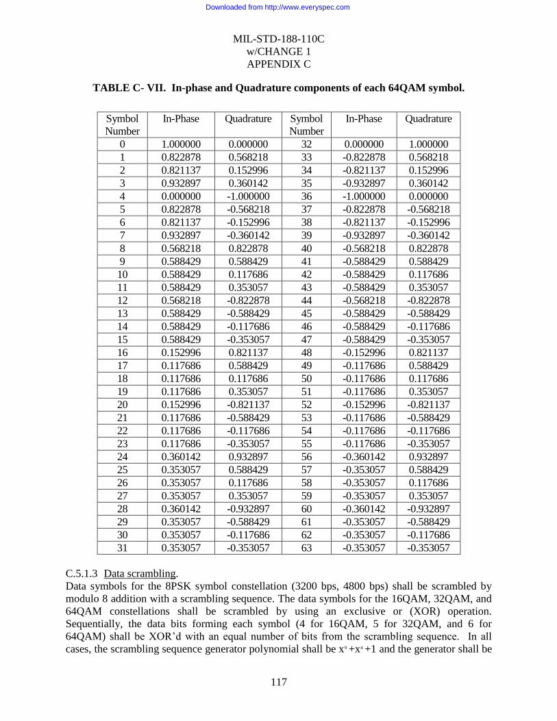
MIL-STD-188-110C
w/CHANGE 1
APPENDIX C
117
TABLE C- VII. In-phase and Quadrature components of each 64QAM symbol.
Symbol
Number
In-Phase Quadrature Symbol
Number
In-Phase Quadrature
0 1.000000 0.000000 32 0.000000 1.000000
1 0.822878 0.568218 33 -0.822878 0.568218
2 0.821137 0.152996 34 -0.821137 0.152996
3 0.932897 0.360142 35 -0.932897 0.360142
4 0.000000 -1.000000 36 -1.000000 0.000000
5 0.822878 -0.568218 37 -0.822878 -0.568218
6 0.821137 -0.152996 38 -0.821137 -0.152996
7 0.932897 -0.360142 39 -0.932897 -0.360142
8 0.568218 0.822878 40 -0.568218 0.822878
9 0.588429 0.588429 41 -0.588429 0.588429
10 0.588429 0.117686 42 -0.588429 0.117686
11 0.588429 0.353057 43 -0.588429 0.353057
12 0.568218 -0.822878 44 -0.568218 -0.822878
13 0.588429 -0.588429 45 -0.588429 -0.588429
14 0.588429 -0.117686 46 -0.588429 -0.117686
15 0.588429 -0.353057 47 -0.588429 -0.353057
16 0.152996 0.821137 48 -0.152996 0.821137
17 0.117686 0.588429 49 -0.117686 0.588429
18 0.117686 0.117686 50 -0.117686 0.117686
19 0.117686 0.353057 51 -0.117686 0.353057
20 0.152996 -0.821137 52 -0.152996 -0.821137
21 0.117686 -0.588429 53 -0.117686 -0.588429
22 0.117686 -0.117686 54 -0.117686 -0.117686
23 0.117686 -0.353057 55 -0.117686 -0.353057
24 0.360142 0.932897 56 -0.360142 0.932897
25 0.353057 0.588429 57 -0.353057 0.588429
26 0.353057 0.117686 58 -0.353057 0.117686
27 0.353057 0.353057 59 -0.353057 0.353057
28 0.360142 -0.932897 60 -0.360142 -0.932897
29 0.353057 -0.588429 61 -0.353057 -0.588429
30 0.353057 -0.117686 62 -0.353057 -0.117686
31 0.353057 -0.353057 63 -0.353057 -0.353057
C.5.1.3 Data scrambling.
Data symbols for the 8PSK symbol constellation (3200 bps, 4800 bps) shall be scrambled by
modulo 8 addition with a scrambling sequence. The data symbols for the 16QAM, 32QAM, and
64QAM constellations shall be scrambled by using an exclusive or (XOR) operation.
Sequentially, the data bits forming each symbol (4 for 16QAM, 5 for 32QAM, and 6 for
64QAM) shall be XOR‟d with an equal number of bits from the scrambling sequence. In all
cases, the scrambling sequence generator polynomial shall be x9 +x4 +1 and the generator shall be
Downloaded from http://www.everyspec.com

MIL-STD-188-110C
w/CHANGE 1
APPENDIX C
118
initialized to 1 at the start of each data frame. A block diagram of the scrambling sequence
generator is shown in figure C-5.
FIGURE C- 5. Scrambling sequence generator illustrating scrambling generator for 8PSK
symbols.
For 8PSK symbols (3200 bps and 4800 bps), the scrambling shall be carried out taking the
modulo 8 sum of the numerical value of the binary triplet consisting of the last (rightmost) three
bits in the shift register, and the symbol number (transcoded value). For example, if the last three
bits in the scrambling sequence shift register were 010 which has a numerical value equal 2, and
the symbol number before scrambling was 6, symbol 0 would be transmitted since: (6+2)
Modulo 8 = 0. For 16QAM symbols, scrambling shall be carried out by XORing the 4 bit
number consisting of the last (rightmost) four bits in the shift register with the symbol number.
For example, if the last 4 bits in the scrambling sequence shift register were 0101 and the
16QAM symbol number before scrambling was 3 (i.e. 0011), symbol 6 (0110) would be
transmitted. For 32QAM symbols, scrambling shall be carried out by XORing the 5 bit number
formed by the last (rightmost) five bits in the shift register with the symbol number. For 64QAM
symbols, scrambling shall be carried out by XORing the 6 bit number formed by the last
(rightmost) six bits in the shift register with the symbol number.
After each data symbol is scrambled, the generator shall be iterated (shifted) the required number
of times to produce all new bits for use in scrambling the next symbol (i.e., 3 iterations for 8PSK,
4 iterations for 16QAM, 5 iterations for 32QAM and 6 iterations for 64QAM). Since the
generator is iterated after the bits are use, the first data symbol of every data frame shall,
therefore, be scrambled by the appropriate number of bits from the initialization value of
00000001.
Downloaded from http://www.everyspec.com
MIL-STD-188-110C
w/CHANGE 1
APPENDIX C
119
The length of the scrambling sequence is 511 bits. For a 256 symbol data block with 6 bits per
symbol, this means that the scrambling sequence will be repeated just slightly more than 3 times,
although in terms of symbols, there will be no repetition.
C.5.1.4 Modulation filter.
The role of the modulation filter is to spectrally constrain the transmit waveform to within the
specified bandwidth. A square root of raised cosine filter is recommended with a roll off factor
(excess bandwidth) of 35%. Utilizing this filter as both the modem modulation filter and
demodulation filter will maximize the signal to noise ratio and minimize inter-symbol
interference. The combined modulation and demodulation filters will have the following
frequency response:
H(f) = 1 for f <= fn – pfn
H(f) = 0.5( 1 – sin(f-fn * PI / 2pfn) for fn-pfn <= f <= fn+pfn
H(f) = 0 elsewhere
Where:
fn is the Nyquist frequency ( fn = 1 / (2T) = 1200 Hz)
p is the roll off factor or excess bandwidth.
The individual modulation and demodulation filters are realized by taking the square root of the
above frequency response.
C.5.2 Frame structure.
The frame structure that shall be used for the waveforms specified in this appendix is shown in
figure C-6. An initial 287 symbol preamble is followed by 72 frames of alternating data and
known symbols. Each data frame shall consist of a data block consisting of 256 data symbols,
followed by a mini-probe consisting of 31 symbols of known data. After 72 data frames, a 72
symbol subset of the initial preamble is reinserted to facilitate late acquisition, Doppler shift
removal, and sync adjustment. It should be noted that the total length of known data in this
segment is actually 103 symbols: the 72 reinserted preamble symbols plus the preceding 31
symbol mini-probe segment which follows the last 256 symbol data block.
Downloaded from http://www.everyspec.com

MIL-STD-188-110C
w/CHANGE 1
APPENDIX C
120
FIGURE C- 6. Frame structure for all waveforms.
C.5.2.1 Synchronization and reinserted preambles.
The synchronization preamble is used for rapid initial synchronization. The reinserted preamble
is used to facilitate acquisition of an ongoing transmission (acquisition on data).
C.5.2.1.1 Synchronization preamble.
The synchronization preamble shall consist of two parts. The first part shall consist of at least N
blocks of 184 8-PSK symbols to be used exclusively for radio and modem AGC. The value of N
shall be configurable to range from values of 0 to 7 (for N=0 this first section is not sent at all).
These 184 symbols shall be formed by taking the complex conjugate of the first 184 symbols of
the sequence specified below for the second section.
The second section shall consist of 287 symbols. The first 184 symbols are intended exclusively
for synchronization and Doppler offset removal purposes while the final 103 symbols, which are
common with the reinserted preamble, also carry information regarding the data rate and
interleaver settings.
... ...
Initial Synchronization Preamble - 287 symbols
Data Block - 256 symbols
Mini-probe - 31 symbols of a repeated 16 symbol
Frank-Heimiller polyphase code
Regularly Re-inserted Preamble -103 symbols
Downloaded from http://www.everyspec.com

MIL-STD-188-110C
w/CHANGE 1
APPENDIX C
121
Expressed as a sequence of 8PSK symbols, using the symbol numbers given in Table C-I the
synchronization preamble shall be as shown in Table C-VIII:
TABLE C- VIII. Synchronization preamble.
1, 5, 1, 3, 6, 1, 3, 1, 1, 6, 3, 7, 7, 3, 5, 4, 3, 6, 6, 4, 5, 4, 0, 2, 2, 2, 6, 0, 7, 5, 7, 4, 0, 7, 5, 7, 1, 6, 1, 0, 5, 2, 2, 6, 2, 3, 6, 0, 0, 5, 1, 4, 2, 2, 2, 3, 4, 0, 6, 2, 7, 4, 3, 3, 7, 2, 0, 2, 6, 4, 4, 1, 7, 6, 2, 0, 6, 2, 3, 6, 7, 4, 3, 6, 1, 3, 7, 4, 6, 5, 7, 2, 0, 1, 1, 1, 4, 4, 0, 0, 5, 7, 7, 4, 7, 3, 5, 4, 1, 6, 5, 6, 6, 4, 6, 3, 4, 3, 0, 7, 1, 3, 4, 7, 0, 1, 4, 3, 3, 3, 5, 1, 1, 1, 4, 6, 1, 0, 6, 0, 1, 3, 1, 4, 1, 7, 7, 6, 3, 0, 0, 7, 2, 7, 2, 0, 2, 6, 1, 1, 1, 2, 7, 7, 5, 3, 3, 6, 0, 5, 3, 3, 1, 0, 7, 1, 1, 0, 3, 0, 4, 0, 7, 3,
0, 0, 0, 0, 0, 2, 4, 6, 0, 4, 0, 4, 0, 6, 4, 2, 0, 0, 0, 0, 0, 2, 4, 6, 0, 4, 0, 4, 0, 6, 4, 2, ( D0, D0, D0, D0, D0, D0, D0, D0, D0, D0, D0, D0, D0 + 0, 4, 0, 4, 0, 0, 4, 4, 0, 0, 0, 0, 0) Modulo 8 ( D1, D1, D1, D1, D1, D1, D1, D1, D1, D1, D1, D1, D1 + 0, 4, 0, 4, 0, 0, 4, 4, 0, 0, 0, 0, 0) Modulo 8 ( D2, D2, D2, D2, D2, D2, D2, D2, D2, D2, D2, D2, D2 + 0, 4, 0, 4, 0, 0, 4, 4, 0, 0, 0, 0, 0) Modulo 8 6, 4, 4, 4, 4, 4, 6, 0, 2, 4, 0, 4, 0, 4, 2, 0, 6, 4, 4, 4, 4, 4, 6, 0, 2, 4, 0, 4, 0, 4, 2, 0
where the data symbols D0, D1, and D2 take one of 30 sets of values chosen from Table C-IX to
indicate the data rate and interleaver settings. The Modulo operations are meant to signify that
each of the D values are used to shift the phase of a length 13 bit Barker code (0101001100000)
by performing modulo 8 addition of the D value with each of the Barker code 13 phase values (0
or 4). This operation can encode 6 bits of information using QPSK modulation of the 13 bit
(chip) Barker codes. Since the three Barker code sequences only occupy 39 symbols, the 31
symbol mini-probes are lengthened to 32 symbols each to provide the additional 2 symbols
required to pad the three 13 symbol Barker codes up to a total of 41 symbols.
Downloaded from http://www.everyspec.com

MIL-STD-188-110C
w/CHANGE 1
APPENDIX C
122
TABLE C- IX. D0, D1, D2 8 PSK symbol values as a function of data rate and interleaver
length.
Interleaver Length in Frames (256 Symbol Data Blocks)
Data Rate
(bps)
1 3 9 18 36 72
3200 0,0,4 0,2,6 0,2,4 2,0,6 2,0,4 2,2,6
4800 0,6,2 0,4,0 0,4,2 2,6,0 2,6,2 2,4,0
6400 0,6,4 0,4,6 0,4,4 2,6,6 2,6,4 2,4,6
8000 6,0,2 6,2,0 6,2,2 4,0,0 4,0,2 4,2,0
9600 6,0,4 6,2,6 6,2,4 4,0,6 4,0,4 4,2,6
12800 6,6,2* reserved reserved reserved reserved reserved
* For 12800 bps 1 frame interleaver shall be interpreted as no interleaving
The mapping chosen to create Table C-IX uses 3 bits each to specify the data rate and interleaver
length. The 3 data rate bits are the 3 most significant bits (MSB) of 3 dibit symbols and the
interleaver length bits are the least significant bits (LSB). The phase of the Barker code is
determined from the 3 resulting dibit words using TABLE C- III, the dibit transcoding Table.
The 3 bit data rate and interleaver length mappings are shown in Table C-X. Note that the
transcoding has the effect of placing the 3 interleaver length bits in quadrature with the 3 data
rate bits.
TABLE C- X. Bit patterns for specifying data rate and interleaver length.
Data Rate 3 Bit Mapping Interleaver Length 3 Bit Mapping Name reserved 000 illegal: see C.5.2.1.2 000
3200 001 1 Frame 001 Ultra Short (US)
4800 010 3 Frames 010 Very Short (VS)
6400 011 9 Frames 011 Short (S)
8000 100 18 Frames 100 Medium (M)
9600 101 36 Frames 101 Long (L)
12800 110 72 Frames 110 Very Long (VL)
reserved 111 illegal: see C.5.2.1.2 111
Because the Barker code is unbalanced in terms of the number of 0s and 1s, the 000 or 111
patterns exhibit a net imbalance in each quadrature component of the 39 symbols that is 12 to 27.
These two patterns are reserved for future standardization of higher data rate modes that employ
constellations more dense than those specified in C.5.1. The other 3-bit patterns are more
balanced (17 to 22) and are used for the more robust constellations.
C.5.2.1.2 Reinserted preamble.
The reinserted preamble shall be identical to the final 72 symbols of the synchronization
preamble. In fact, the final 103 symbols are common between the synchronization preamble and
Downloaded from http://www.everyspec.com

MIL-STD-188-110C
w/CHANGE 1
APPENDIX C
123
the contiguous block consisting of the reinserted preamble and the mini-probe which
immediately precedes it. The 103 symbols of known data (including the 31 mini-probe symbols
of the preceding data frame) are thus:
TABLE C- XI. Reinserted preamble.
0, 0, 0, 0, 0, 2, 4, 6, 0, 4, 0, 4, 0, 6, 4, 2, 0, 0, 0, 0, 0, 2, 4, 6, 0, 4, 0, 4, 0, 6, 4,
2,
( D0, D0, D0, D0, D0, D0, D0, D0, D0, D0, D0, D0, D0 + 0, 4, 0, 4, 0, 0, 4, 4, 0, 0, 0, 0, 0) Modulo 8
( D1, D1, D1, D1, D1, D1, D1, D1, D1, D1, D1, D1, D1 + 0, 4, 0, 4, 0, 0, 4, 4, 0, 0, 0, 0, 0) Modulo 8
( D2, D2, D2, D2, D2, D2, D2, D2, D2, D2, D2, D2, D2 + 0, 4, 0, 4, 0, 0, 4, 4, 0, 0, 0, 0, 0) Modulo 8
6,
4, 4, 4, 4, 4, 6, 0, 2, 4, 0, 4, 0, 4, 2, 0, 6, 4, 4, 4, 4, 4, 6, 0, 2, 4, 0, 4, 0, 4, 2, 0;
where the data symbols D0, D1, and D2 again take one of 30 sets of values chosen from Table C-
IX to indicate the data rate and interleaver settings as described in the Synchronization Preamble
section above. The first 31 of these symbols are the immediately preceding mini-probe, which
follows the last of the 72 data blocks.
Note that the 3 Bit Mappings for Interleaver Length of 000 or 111 may result in an S0 to S8
pattern that could be confused with the fixed (- - - - - - - +) mini probe pattern. For this reason,
these mappings are referred to as “illegal” in Table C-X.
C.5.2.2 Mini-probes.
Mini-probes 31 symbols in length shall be inserted following every 256 symbol data block and at
the end of each preamble (where they are considered to be part of the preamble). Using the 8PSK
symbol mapping, each mini-probe shall be based on the repeated Frank-Heimiller sequence. The
sequence that shall be used, specified in terms of the 8PSK symbol numbers, is given by:
0, 0, 0, 0, 0, 2, 4, 6, 0, 4, 0, 4, 0, 6, 4, 2, 0, 0, 0, 0, 0, 2, 4, 6, 0, 4, 0, 4, 0, 6, 4.
This mini-probe will be designated ‘+’.
The phase inverted version of this is:
4, 4, 4, 4, 4, 6, 0, 2, 4, 0, 4, 0, 4, 2, 0, 6, 4, 4, 4, 4, 4, 6, 0, 2, 4, 0, 4, 0, 4, 2, 0
and mini-probes using this sequence will be designated „-‟, as the phase of each symbol has been
rotated 180 degrees from the ‘+’.
There are a total of 73 mini-probes for each set of 72 data blocks. For convenience, each mini-
probe will be sequentially numbered, with mini-probe 0 being defined as the last 31 symbols of
Downloaded from http://www.everyspec.com

MIL-STD-188-110C
w/CHANGE 1
APPENDIX C
124
the preceding (reinserted) preamble, mini-probe number 1 following the first data block after a
(reinserted) preamble. Mini-probe 72 follows the 72nd data block, and is also the first 31
symbols of the next 103 symbol reinserted preamble. Mini-probes 0 and 72 have been defined as
part of the reinsertion preamble to have the signs - and + respectively. The data rate and
interleaver length information encoded into the synchronization and reinserted preambles shall
also be encoded into mini-probes 1 through 72. These 72 mini-probes are grouped into four sets
of 18 consecutive mini-probes (1 to 18, 19 to 36, 37 to 54, and 55 to 72). Note that the 256
symbol data block that immediately follows the 18th
mini-probe, in each of the first three sets, is
also the 1st data block of an interleaver block with frame lengths of 1, 3, 9, and 18. The length 36
interleaver block begins after the second set, and a reinserted preamble begins after the fourth
set. This structure permits data to begin to be demodulated as soon as the interleaver boundary
becomes known.
Each 18 mini-probe sequence shall consists of seven – signs, a + sign, followed by six sign
values that are dependent on the data rate and interleaver length, three sign values that specify
which of the four sets of 18 mini-probes it is, and then finally a + sign. For the fourth set, this
final + sign (mini-probe 72) is also the initial mini-probe of the next reinserted preamble (which
uses the + phase).
Pictorially, this length 18 sequence is: - - - - - - - + S0 S1 S2 S3 S4 S5 S6 S7 S8 +, where the first six
Si sign values are defined in Table C-XII. Note that these 6 bit patterns ( + is a 0 ) correspond to
the concatenation of the 3 bit mappings from Table C-X for the data rate (S0 S1 S2) and the
interleaver length (S3 S4 S5). The final three Si sign values which specify the mini-probe set
(count) are defined in Table C-XIII.
TABLE C- XII. S0, S1, S2, S3, S4, S5 (sign) values as a function of data rate and
interleaver setting.
Data Rate
(bps)
Interleaver Length in Frames (256 Symbol Data Blocks)
1 3 9 18 36 72
3200 + + - + + - + + - + - + + + - + - - + + - - + + + + - - + - + + - - - +
4800 + - + + + - + - + + - + + - + + - - + - + - + + + - + - + - + - + - - +
6400 + - - + + - + - - + - + + - - + - - + - - - + + + - - - + - + - - - - +
8000 - + + + + - - + + + - + - + + + - - - + + - + + - + + - + - - + + - - +
9600 - + - + + - - + - + - + - + - + - - - + - - + + - + - - + - - + - - - +
12800 - - + + + - N/A N/A N/A N/A N/A
TABLE C- XIII. S6, S7, S8 (sign) values as a function of mini-probe set.
Mini-probe set
1 to 18 19 to 36 37 to 54 55 to 72 + + - + - + + - - - + +
Downloaded from http://www.everyspec.com

MIL-STD-188-110C
w/CHANGE 1
APPENDIX C
125
The 1st eight mini-probes in each set (- - - - - - - +) uniquely locate the starting point for the
following nine Si values. This is possible since the Si sequences used contain at most runs of four
+ or - phases. This makes it impossible for a sequence of 7 mini-probes with the same phase
followed by one with a phase reversal to occur anywhere else except at the beginning of one of
the 18 mini-probe sequences. Once this fixed 8 mini-probe pattern is located, the 0 or 180
degree phase ambiguity is also resolved so that the following 9 mini-probes can be properly
matched to the data rate, interleaver length, and mini-probe set count. The entire mini-probe
sequence shall therefore be as follows:
[rp] - - - - - - - + S0 S1 S2 S3 S4 S5 S6 S7 S8 + - - - - - - - + S0 S1 S2 S3 S4 S5 S6 S7 S8 +
- - - - - - - + S0 S1 S2 S3 S4 S5 S6 S7 S8 + - - - - - - - + S0 S1 S2 S3 S4 S5 S6 S7 S8 [rp]
where the [rp] represents the 103 reinserted preamble symbols (includes mini-probes 72 and 0).
C.5.3 Coding and interleaving.
The interleaver used shall be a block interleaver. Each block of input data shall also be encoded
using a block encoding technique with a code block size equal to the size of the block
interleaver. Thus, the input data bits will be sent as successive blocks of bits that span the
duration of the interleaver length selected. Table C-XIV shows the number of input data bits per
block as function of both data rate and interleaver length. Note that an “input data block” should
not be confused with the 256 symbol data block that is part of a data frame in the waveform
format. The bits from an input data block will be mapped through the coding and interleaving to
the number of data frames, and thus 256 symbol data blocks, that define the interleaver length.
TABLE C- XIV. Input data block size in bits as a function of data rate and interleaver
length
Data Rate (bps)
Interleaver Length in Frames
1 3 9 18 36 72
Number of Input Data Bits per Block
3200 384 1,152 3,456 6,912 13,824 27,648
4800 576 1,728 5,184 10,368 20,736 41,472
6400 768 2,304 6,912 13,824 27,648 55,296
8000 960 2,880 8,640 17,280 34,560 69,120
9600 1152 3,456 10,368 20,736 41,472 82,944
C.5.3.1 Block boundary alignment.
Each code block shall be interleaved within a single interleaver block of the same size. The
boundaries of these blocks shall be aligned such that the beginning of the first data frame
following each reinserted preamble shall coincide with an interleaver boundary. Thus for an
interleaver length of 3 frames, the first three data frames following a reinserted preamble will
Downloaded from http://www.everyspec.com

MIL-STD-188-110C
w/CHANGE 1
APPENDIX C
126
contain all of the encoded bits for a single input data block. The first data symbol from the first
data frame in each interleaver set shall have as its MSB the first bit fetched from the interleaver.
This is no different from what would normally be expected, but is a requirement.
C.5.3.2 Block encoding.
The full-tail-biting and puncturing techniques shall be used with a rate 1/2 convolutional code to
produce a rate 3/4 block code that is the same length as the interleaver.
C.5.3.2.1 Rate 1/2 convolutional code.
A constraint length 7, rate 1/2 convolutional code shall be used prior to puncturing. This shall be
the same code as is used in the single-tone waveform described in section 5.3.2 of this standard.
figure C-7 is a pictorial representation of the encoder.
Downloaded from http://www.everyspec.com

MIL-STD-188-110C
w/CHANGE 1
APPENDIX C
127
x6 1xx2x3x4x5
+
+
OUTPUT
SWITCH RATE
= TWICE INPUT
SYMBOL RATE
T1(X)
T2(X)
I(X)
INPUT
CONSTRAINT LENGTH = 7
GENERATOR POLYNOMIALS:
FOR T1 X6+X4+X3+X+1
FOR T2 X6+X5+X4+X3+1
FIGURE C- 7. Constraint length 7, rate 1/2 convolutional encoder.
The two summing nodes in the figure represent modulo 2 addition. For each bit input to the
encoder, two bits are taken from the encoder, with the upper output bit, T1(x), taken first.
C.5.3.2.2 Full-tail-biting encoding.
To begin encoding each block of input data, the encoder shall be preloaded by shifting in the first
six input data bits without taking any output bits. These six input bits shall be temporarily saved
so that they can be used to “flush” the encoder. The first two coded output bits shall be taken
after the seventh bit has been shifted in, and shall be defined to be the first two bits of the
resulting block code. After the last input data bit has been encoded, the first six “saved” data bits
Downloaded from http://www.everyspec.com
MIL-STD-188-110C
w/CHANGE 1
APPENDIX C
128
shall be encoded. Note that the encoder shift register should not be changed before encoding
these saved bits; i.e., it should be filled with the last seven input data bits. The six “saved” data
bits are encoded by shifting them into the encoder one at a time, beginning with the earliest of
the six. The encoding thus continues by taking the two resulting coded output bits as each of the
saved six bits is shifted in. These encoded bits shall be the final bits of the resulting
(unpunctured) block code. Prior to puncturing, the resulting block code will have exactly twice
as many bits as the input information bits. Puncturing of the rate 1/2 code to the required rate 3/4
shall be done prior to sending bits to the interleaver.
C.5.3.2.3 Puncturing to rate 3/4.
In order to obtain a rate 3/4 code from the rate 1/2 code used, the output of the encoder must be
punctured by not transmitting 1 bit out of every 3. Puncturing shall be performed by using a
puncturing mask of 1 1 1 0 0 1, applied to the bits output from the encoder. In this notation a 1
indicates that the bit is retained and a 0 indicates that the bit is not transmitted. For an encoder
generated sequence of
T1(k), T2(k), T1(k+1), T2(k+1), T1(k+2), T2(k+2) . . .
the transmitted sequence shall be
T1(k), T2(k), T1(k+1), T2(k+2) . . .
Defining T1(0), T2(0) to be the first two bits of the block code generated as defined in paragraph
C.5.3.2, then the value of k in the above sequences shall be an integral multiple of 3. The block
code shall be punctured in this manner before being input to the interleaver.
C.5.3.3 Block interleaver structure.
The block interleaver used is designed to separate neighboring bits in the punctured block code
as far as possible over the span of the interleaver with the largest separations resulting for the bits
that were originally closest to each other. Because of the 30 different combinations of data rates
and interleaver lengths, a more flexible interleaver structure than used for the single-tone
waveform described in section 5.3.2 of this standard is needed. The structure to be used is
actually simpler than that used previously.
Downloaded from http://www.everyspec.com

MIL-STD-188-110C
w/CHANGE 1
APPENDIX C
129
C.5.3.3.1 Interleaver size in bits.
The interleaver shall consist of a single dimension array, numbered from 0 to its size in bits –1.
The array size shall depend on both the data rate and interleaver length selected as shown in
Table C-XV.
TABLE C- XV. Interleaver size in bits as a function of data rate and interleaver length.
Data Rate
(bps)
Interleaver Length in Frames
1 3 9 18 36 72
Interleaver Size in Bits
3200 512 1536 4608 9216 18,432 36,864
4800 768 2304 6912 13,824 27,648 55,296
6400 1024 3072 9216 18,432 36,864 73,728
8000 1280 3840 11,520 23,040 46,080 92,160
9600 1536 4608 13,824 27,648 55,296 110,592
C.5.3.3.2 Interleaver load.
The punctured block code bits shall be loaded into the interleaver array beginning with location
0. The location for loading each successive bit shall be obtained from the previous location by
incrementing by the “Interleaver Increment Value” specified in Table C-XVI, modulo the
“Interleaver Size in Bits.”
Defining the first punctured block code bit to be B(0), then the load location for B(n) is given by:
Load Location = ( n * Interleaver Increment Value) Modulo (Interleaver Size in Bits)
Thus for 3200 bps, with a one frame interleaver (512 bit size with an increment of 97), the first 8
interleaver load locations are: 0, 97, 194, 291, 388, 485, 70, and 167.
TABLE C- XVI. Interleaver increment value as a function of data rate and interleaver
length.
Data Rate
(bps)
Interleaver Length in Frames
1 3 9 18 36 72
Interleaver Increment Value
3200 97 229 805 1393 3281 6,985
4800 145 361 1045 2089 5137 10,273
6400 189 481 1393 3281 6985 11,141
8000 201 601 1741 3481 8561 14,441
9600 229 805 2089 5137 10,273 17,329
These increment values have been chosen to ensure that the combined cycles of puncturing and
assignment of bit positions in each symbol for the specific constellation being used is the same as
Downloaded from http://www.everyspec.com

MIL-STD-188-110C
w/CHANGE 1
APPENDIX C
130
if there had been no interleaving. This is important, because each symbol of a constellation
contains “strong” and “weak” bit positions, except for the lowest data rate. Bit position refers to
the location of the bit, ranging from MSB to LSB, in the symbol mapping. A strong bit position
is one that has a large average distance between all the constellation points where the bit is a 0
and the closest point where it is a 1. Typically, the MSB is a strong bit and the LSB a weak bit.
An interleaving strategy that did not evenly distribute these bits in the way they occur without
interleaving could degrade performance.
C.5.3.3.3 Interleaver fetch.
The fetching sequence for all data rates and interleaver lengths shall start with location 0 of the
interleaver array and increment the fetch location by 1. This is a simple linear fetch from
beginning to end of the interleaver array.
C.5.4 Operational features and message protocols.
The format of this narowband MDR waveform has been designed to permit it to work well with
most of the protocols used and planned for use with HF. The reinserted preamble facilitates
acquisition (or re-acquisition) of an ongoing broadcast transmission. The short length of the
synchronization preamble, wide range of interleaving lengths, and the use of full-tail-biting
coding is intended to provide efficient operation with ARQ protocols. To further enhance the
operation with these protocols, the following operational features shall be included in the HF
modem.
C.5.4.1 User interfaces.
C.5.4.1.1 Conventional asynchronous interface.
In addition to the standard synchronous serial interface (see 4.2.3), the modem shall also be
capable of interfacing with an asynchronous DTE. In this case the DTE provides (accepts)
asynchronous Words consisting of a Start Bit, an N bit Character, and some minimum number of
Stop Bits. Additional Stop Bits are provided (accepted) by the DTE between Words as necessary
to accommodate gaps between their occurrence. Interoperability shall be provided for those
cases where the value of N, the number of Bits in the Character, is 5,6,7, or 8 (including any
parity bits), and the minimum number of Stop Bits is 1 or 2. Hence interoperability is defined for
those cases where the number of Bits in the Word is N+2 and N+3. In these cases the entire N+2
or N+3 bits of the Word shall be conveyed contiguously in the modulated signal. Additional Stop
Bits shall be conveyed as necessary to accommodate gaps in data from the DTE; there shall be
no modem-defined null character incorporated into the modulated signal.
C.5.4.1.2 High speed asynchronous user interface with flow control.
Certain high speed user interfaces provide data to (and accept data from) the modem in units of 8
bit bytes. Furthermore, the Input Data Blocks shown in Table C-XIV are all multiples of 8 bit
bytes. An optional mode shall be provided to accommodate the special case of an 8 bit character
(which includes any parity check bits) and a 1.0 unit interval Stop Bit. In this optional mode, the
8 bit Character shall be aligned with the 256 symbol modem frame boundary, and no Start or
Stop Bits shall be transmitted. In this mode of operation it is assumed that the DTE data rate is
greater than that which can be accommodated by the modem. Consequently flow control shall be
Downloaded from http://www.everyspec.com

MIL-STD-188-110C
w/CHANGE 1
APPENDIX C
131
used to temporarily stop data flow from the DTE to the modem when the modem‟s input buffer
becomes full. Conversely, when the modem‟s input buffer becomes empty, the modem shall
assume that the DTE has finished its message, and the modem shall initiate its normal message-
termination procedure. This method of operation obviates the need for the transmission of Null
characters for the purpose of “rate padding.” Consequently, no Null characters shall be
transmitted for this purpose.
C.5.4.1.3 Ethernet interface.
The modem shall provide an Ethernet interface (see Appendix A) for byte oriented user data
transfers (see C.5.4.1.2), and these bytes shall be aligned with the Input Data Block boundaries.
C.5.4.2 Onset of transmission.
The modem shall begin a transmission no later than 100 ms after it has received an entire input
data block (enough bits to fill a coded and interleaved block), or upon receipt of the last input
data bit, whichever occurs first. The latter would only occur when the message is shorter than
one interleaver block. A transmission shall be defined as beginning with the keying of the radio,
followed by the output of the preamble waveform after the configured pre-key delay, if any.
The delay between when the modem receives the first input data bit and the onset of transmission
will be highly dependent on the means for delivery of the input data bits to the modem. A
synchronous serial interface at the user data rate will have the greatest delay. For this reason it is
recommended that a high speed asynchronous interface (serial or Ethernet port) with flow-
control be used if this delay is of concern for the deployed application.
C.5.4.3 End of message.
The use of an end-of-message (EOM) in the transmit waveform shall be a configurable option.
When the use of an EOM has been selected, a 32-bit EOM pattern shall be appended after the
last input data bit of the message. The EOM, expressed in hexadecimal notation is 4B65A5B2,
where the left most bit is sent first. If the last bit of the EOM does not fill out an input data
block, the remaining bits in the input data block shall be set to zero before encoding and
interleaving the block.
If the use of an EOM has been inhibited, and the last input data bit does not fill out an input data
block, the remaining bits in the input data block shall be set to zero before encoding and
interleaving the block. It is anticipated that the use of an EOM will only be inhibited when an
ARQ data protocol uses ARQ blocks which completely fill (or nearly so) the selected input data
block size (interleaver block). Without this feature, the use of an EOM would require the
transmission of an additional interleaver block under these circumstances.
C.5.4.4 Termination of a transmission.
Upon receipt of a radio silence (or equivalent) command, the modem shall immediately un-key
the radio and terminate its transmit waveform.
In normal operation, the modem shall terminate a transmission only after the transmission of the
final data frame, including a mini-probe, associated with the final interleaver block. Note that a
data frame consists of a 256 symbol data block followed by a mini-probe. Note that any signal
Downloaded from http://www.everyspec.com

MIL-STD-188-110C
w/CHANGE 1
APPENDIX C
132
processing and/or filter delays in the modem and the HF transmitter must be accounted for (as
part of the key line control timing) to ensure that the entire final mini-probe is transmitted before
the transmitter power is turned off.
C.5.4.5 Termination of receive data processing.
There are a number of events which shall cause the HF modem to cease processing the received
signal to recover data, and return to the acquisition mode. These are necessary because a modem
is not able to acquire a new transmission while it is attempting to demodulate and decode data.
C.5.4.5.1 Detection of EOM.
The HF modem shall always scan all of the decoded bits for the 32-bit EOM pattern defined in
paragraph C.5.4.3. Upon detection of the EOM the modem shall return to the acquisition mode.
The modem shall continue to deliver decoded bits to the user (DTE) until the final bit
immediately preceding the EOM has been delivered.
C.5.4.5.2 Command to return to acquisition.
Upon receipt of a command to terminate reception, the HF modem shall return to the acquisition
mode and terminate the delivery of decoded bits to the user (DTE).
C.5.4.5.3 Receipt of a specified number of data blocks.
The maximum message duration measured in number of Input Data Blocks (interleaver blocks)
shall be a configurable parameter. One value of this parameter shall specify that an unlimited
number may be received. Once the modem has decoded and delivered to the user (DTE), the
number of bits corresponding to the configured maximum message duration, the HF modem
shall return to the acquisition mode and terminate the delivery of decoded bits to the user (DTE).
Note that for a given interleaver length, this parameter also specifies the maximum message
duration in time, independent of the bit rate. Note that this parameter is the maximum duration
and that the transmit end always has the option of using an EOM for shorter transmissions.
Operation with a specified number of input data blocks may be used by an ARQ protocol where
the size of the ARQ packet is fixed, or occasionally changed to accommodate changing
propagation conditions. In this case we anticipate that this parameter (maximum message
duration) will be sent to the receiving end of the link as part of the ARQ protocol. It would then
be sent to the receiving modem through the remote control interface (see C.5.4.6 below), since it
is not embedded in the waveform itself as the data rate and interleaver length parameters are.
C.5.4.5.4 Initiation of a transmission.
If, and only if, the HF Modem is configured to operate in half-duplex mode with transmit
override, the initiation of a transmission by the user (DTE) shall cause the HF modem to
terminate the receive processing and the delivery of decoded bits to the user (DTE).
C.5.4.6 Remote control.
The remote control interface (see section 5.3.1.5) shall provide the capability to specify the
following parameters and commands:
a. MDR waveform parameters:
1) The 5 data rates for the MDR waveform
Downloaded from http://www.everyspec.com

MIL-STD-188-110C
w/CHANGE 1
APPENDIX C
133
2) The 6 interleaver lengths for the MDR waveform
b. A command to select the usage of the optional EOM in the transmit waveform. Note that the
receiving modem must always scan for the EOM regardless of this setting.
c. A command to specify the maximum message duration measured in number of Input Data
Blocks (interleaver blocks). The value of 0 (zero) for this parameter shall specify that an
unlimited number may be received.
d. A command to cause the modem to terminate receive data processing and return to
acquisition mode.
Downloaded from http://www.everyspec.com

MIL-STD-188-110C
w/CHANGE 1
APPENDIX C
134
C.6 PERFORMANCE
C.6.1 BER performance.
The measured performance of the narrowband MDR waveform, using fixed-frequency operation
and employing the maximum interleaving period (the 72-frame “Very Long” interleaver), shall
achieve coded BER of no more than 1.0E-5 under each of the conditions listed in Table C-XVII.
TABLE C- XVII. MDR waveform performance requirements.
User data Average SNR (dB) for BER ≤ 1.0E-5
rate (bps) AWGN Channel ITU-R Poor Channel
12800 27 -
9600 21 31
8000 19 27
6400 16 23
4800 13 19
3200 9 14
Performance shall be tested using a baseband HF simulator patterned after the Watterson Model
in accordance with Appendix E.
The AWGN channel shall consist of a single, non-fading path. Each condition shall be
measured for at least 60 minutes.
The ITU-R Poor channel shall consist of two independent but equal average power
Rayleigh fading paths, with a fixed 2 ms delay between paths, and with a fading (two
sigma) bandwidth (BW) of 1 Hz. Each condition shall be measured for at least 5 hours.
Both signal and noise power shall be measured in a 3 kHz bandwidth. Note that the
average power of QAM symbols is different from that of the 8PSK mini-probes and
reinserted preambles; the measured signal power shall be the long-term average of user
data, mini-probe, and reinserted preamble symbols.
When testing a modem embedded with a radio, so that only radio frequency (RF) signals are
available for testing, the RF signals must be downconverted to baseband for processing by the
channel simulator, and the result upconverted to RF for the receiver. In this case, the built-in
radio filters will affect the performance of the modems. Therefore, when testing embedded
modems, the SNR values specified in Table C-XVII shall be increased by 2 dB (3 dB at 9600
bps and above).
When the sending and receiving modems used in this test are not identical make and model, an
extra dB of SNR shall be allowed due to potential degradation in mismatched filters.
C.6.2 Acquisition performance.
Not yet standardized.
Downloaded from http://www.everyspec.com

MIL-STD-188-110C
w/CHANGE 1
APPENDIX C
135
C.6.3 Doppler shift test.
The modem shall acquire and maintain synchronization for at least 5 minutes with a test signal
having the following characteristics: 9600 bps/Very Long interleaver, 75 Hz frequency offset, 2
ms delay spread, a fading BW of 1 Hz, and an average SNR of 30 dB. The test shall be repeated
with a –75 Hz frequency offset. No BER test is required.
C.6.4 Doppler sweep performance.
The AWGN BER test at 9600 bps from Table C-XVII shall be repeated with a test signal having
a frequency offset that continuously varies at a rate of 3.5 Hz/s between the limits of -75 and +75
Hz, such that a plot of frequency offset vs. time describes a periodic “triangle” waveform having
a period of (300/3.5) seconds. Over a test duration of 1 hour, the modem shall achieve a BER of
1.0E-5 or less at an SNR of 24 dB.
C.7 ASSOCIATED COMMUNICATIONS EQUIPMENT
The QAM constellations specified in this appendix are more sensitive to equipment variations
than the PSK constellations specified in section 5.3.2 of this standard. Because of this sensitivity,
radio filters will have a significant impact on the performance of modems implementing the
waveforms in this appendix. In addition, because of the level sensitive nature of the QAM
constellations, turn-on transients, AGC, and ALC can cause significant performance degradation.
It is recommended that modems implementing the waveforms in this appendix should include a
variable pre-key feature, by which the user can specify a delay between the time when the
transmitter is keyed and the modem signal begins. This allows for turn-on transient settling,
which is particularly important for legacy radio equipment.
It is recommended that a slow AGC setting (e.g., the “nondata” mode in MIL-STD-188-141) be
used when receiving the waveforms in this appendix.
Downloaded from http://www.everyspec.com

MIL-STD-188-110C
w/CHANGE 1
APPENDIX D
135
HF DATA MODEM WAVEFORMS FOR SINGLE CONTIGUOUS BANDWIDTHS
UP TO 24 KHZ
TABLE OF CONTENTS
PARAGRAPH .................................................................................................................................. PAGE
D.1 GENERAL .................................................................................................................................... 140
D.1.1 Scope. ............................................................................................................................................ 140
D.1.2 Applicability. ............................................................................................................................. 140
D.2 APPLICABLE DOCUMENTS ................................................................................................... 140
D.3 DEFINITIONS ............................................................................................................................. 140
D.3.1 Abbreviations and acronyms. .................................................................................................... 140
D.4 GENERAL REQUIREMENTS .................................................................................................. 141
D.4.1 WBHF Block 1 Requirements .................................................................................................. 141
D.4.2 WBHF Block 2 Requirements .................................................................................................. 141
D.4.3 WBHF Block 3 Requirements .................................................................................................. 141
D.5 DETAILED REQUIREMENTS ................................................................................................. 142
D.5.1 Modulation. ................................................................................................................................... 142
D.5.1.1 Known symbols. ......................................................................................................................142
D.5.1.2 Data symbols............................................................................................................................142
D.5.1.2.1 PSK data symbols. ................................................................................................................144
D.5.1.2.2 QAM data symbols...............................................................................................................147
D.5.1.2.3 Walsh Orthogonal Modulation. ...........................................................................................157
D.5.1.3 Data scrambling. ......................................................................................................................157
D.5.1.4 Waveform ID 0 Walsh Orthogonal Modulation Data scrambling. .......................................159
D.5.1.5 Modulation filter. .....................................................................................................................160
D.5.2 Frame structure. ......................................................................................................................... 161
D.5.2.1 Synchronization preamble. ......................................................................................................163
D.5.2.1.1 4-ary Orthogonal Walsh Modulation in the preamble. .......................................................163
D.5.2.1.2 TLC Section. .........................................................................................................................164
D.5.2.1.3 Synchronization Section. ......................................................................................................164
D.5.2.2 Mini-probes. .............................................................................................................................168
D.5.3 Coding and interleaving. ........................................................................................................... 187
D.5.3.1 Block boundary alignment. .....................................................................................................196
D.5.3.2 Block encoding. .......................................................................................................................196
Downloaded from http://www.everyspec.com

MIL-STD-188-110C
w/CHANGE 1
APPENDIX D
136
D.5.3.2.1 Constraint length 7, rate 1/2 convolutional code.................................................................198
D.5.3.2.2 Constraint length 9, rate 1/2 convolutional code.................................................................199
D.5.3.2.3 Full-tail-biting encoding. ......................................................................................................199
D.5.3.2.4 Puncturing and Repetition. ...................................................................................................200
D.5.3.3 Block interleaver structure. .....................................................................................................201
D.5.3.3.1 Interleaver size in bits. ..........................................................................................................201
D.5.3.3.2 Interleaver load. ....................................................................................................................201
D.5.3.3.3 Interleaver fetch. ...................................................................................................................209
D.5.4 Operational features and message protocols. ........................................................................... 210
D.5.4.1 User interfaces. ........................................................................................................................210
D.5.4.1.1 Conventional synchronous interface. ..................................................................................210
D.5.4.1.2 Conventional asynchronous interface. .................................................................................210
D.5.4.1.3 High speed asynchronous user interface with flow control. ...............................................210
D.5.4.1.4 Ethernet interface. .................................................................................................................210
D.5.4.2 Onset of transmission. .............................................................................................................211
D.5.4.3 End of message. .......................................................................................................................211
D.5.4.4 Termination of a transmission. ................................................................................................211
D.5.4.5 Termination of receive data processing. .................................................................................213
D.5.4.5.1 Detection of EOM. ...............................................................................................................214
D.5.4.5.2 Command to return to acquisition. ......................................................................................214
D.5.4.5.3 Receipt of a specified number of data blocks. ....................................................................214
D.5.4.5.4 Initiation of a transmission. ..................................................................................................214
D.5.4.6 Remote control. ........................................................................................................................214
D.6 PERFORMANCE ........................................................................................................................ 215
D.6.1 BER performance on AWGN and Multipath Fading Channels ............................................. 215
D.6.2 BER performance on static multipath channels ....................................................................... 216
D.6.3 Acquisition performance. .......................................................................................................... 217
D.6.4 Doppler shift test. ....................................................................................................................... 217
D.6.5 Doppler sweep performance. .................................................................................................... 218
D.7 ASSOCIATED COMMUNICATIONS EQUIPMENT ............................................................ 218
Downloaded from http://www.everyspec.com

MIL-STD-188-110C
w/CHANGE 1
APPENDIX D
137
LIST OF FIGURES
FIGURE D-1. 8PSK SIGNAL CONSTELLATION AND SYMBOL MAPPING. ...................146
FIGURE D-2. 16QAM SIGNALING CONSTELLATION. ........................................................147
FIGURE D-3. 32QAM SIGNALING CONSTELLATION. ........................................................149
FIGURE D-4. 64QAM SIGNALING CONSTELLATION. ........................................................150
FIGURE D-5. 256QAM SIGNALING CONSTELLATION. ......................................................152
FIGURE D-6. SCRAMBLING SEQUENCE GENERATOR ILLUSTRATING
SCRAMBLING GENERATOR FOR PSK SYMBOLS. ...........................................158
FIGURE D-7. FRAME STRUCTURE FOR WAVEFORMS 1-13. ...........................................161
FIGURE D-8. SYNCHRONIZATION PREAMBLE STRUCTURE. ........................................163
FIGURE D-9. CONSTRAINT LENGTH 7, RATE 1/2 CONVOLUTIONAL ENCODER. .....198
FIGURE D-10. CONSTRAINT LENGTH 9, RATE 1/2 CONVOLUTIONAL ENCODER. ...199
LIST OF TABLES
TABLE D-I. SYMBOL RATES AND SUB CARRIER ................................................................142
TABLE D-II. MODULATION USED TO OBTAIN EACH DATA RATE. .............................143
TABLE D-III. TRANSCODING FOR BPSK. ..............................................................................144
TABLE D-IV. TRANSCODING FOR QPSK. ..............................................................................145
TABLE D-V. TRANSCODING FOR 8PSK. ................................................................................145
TABLE D-VI. 8PSK SYMBOL MAPPING. .................................................................................146
TABLE D-VII. IN-PHASE AND QUADRATURE COMPONENTS OF EACH 16QAM
SYMBOL. ......................................................................................................................148
TABLE D-VIII. IN-PHASE AND QUADRATURE COMPONENTS OF EACH 32QAM
SYMBOL. ......................................................................................................................149
TABLE D-IX. IN-PHASE AND QUADRATURE COMPONENTS OF EACH 64QAM
SYMBOL. ......................................................................................................................151
TABLE D-X. IN-PHASE AND QUADRATURE COMPONENTS OF EACH 256QAM
SYMBOL. ......................................................................................................................153
TABLE D- XI. NUMBER OF UNKNOWN (DATA) SYMBOLS IN FRAME ........................162
TABLE D- XII. NUMBER OF KNOWN SYMBOLS (MINI-PROBE) IN FRAME ................162
TABLE D-XIII. LENGTH OF PREAMBLE SYNCHRONIZATION SECTION CHANNEL
SYMBOLS .....................................................................................................................163
TABLE D-XIV. WALSH SEQUENCES FOR SYNCHRONIZATION SECTION OF THE
PREAMBLE ..................................................................................................................164
TABLE D-XV. TLC / FIXED SYNCHRONIZATION PREAMBLE .........................................167
TABLE D-XVI. COUNT SYNCHRONIZATION PREAMBLE. ...............................................167
TABLE D-XVII. WAVEFORM NUMBER SYNCHRONIZATION PREAMBLE. ................168
TABLE D-XVIII. WAVEFORM NUMBER MAPPING. ............................................................166
TABLE D-XIX. INTERLEAVER SELECTION MAPPING. .....................................................166
TABLE D-XX. CONSTRAINT LENGTH AND VOICE MODE MAPPING. .........................167
Downloaded from http://www.everyspec.com
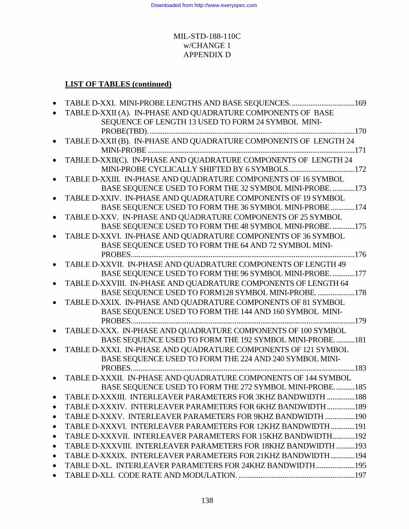
MIL-STD-188-110C
w/CHANGE 1
APPENDIX D
138
LIST OF TABLES (continued)
TABLE D-XXI. MINI-PROBE LENGTHS AND BASE SEQUENCES. ..................................169
TABLE D-XXII (A). IN-PHASE AND QUADRATURE COMPONENTS OF BASE
SEQUENCE OF LENGTH 13 USED TO FORM 24 SYMBOL MINI-
PROBE(TBD). ...............................................................................................................170
TABLE D-XXII (B). IN-PHASE AND QUADRATURE COMPONENTS OF LENGTH 24
MINI-PROBE ................................................................................................................171
TABLE D-XXII(C). IN-PHASE AND QUADRATURE COMPONENTS OF LENGTH 24
MINI-PROBE CYCLICALLY SHIFTED BY 6 SYMBOLS ....................................172
TABLE D-XXIII. IN-PHASE AND QUADRATURE COMPONENTS OF 16 SYMBOL
BASE SEQUENCE USED TO FORM THE 32 SYMBOL MINI-PROBE. ............173
TABLE D-XXIV. IN-PHASE AND QUADRATURE COMPONENTS OF 19 SYMBOL
BASE SEQUENCE USED TO FORM THE 36 SYMBOL MINI-PROBE .............174
TABLE D-XXV. IN-PHASE AND QUADRATURE COMPONENTS OF 25 SYMBOL
BASE SEQUENCE USED TO FORM THE 48 SYMBOL MINI-PROBE. ............175
TABLE D-XXVI. IN-PHASE AND QUADRATURE COMPONENTS OF 36 SYMBOL
BASE SEQUENCE USED TO FORM THE 64 AND 72 SYMBOL MINI-
PROBES. ........................................................................................................................176
TABLE D-XXVII. IN-PHASE AND QUADRATURE COMPONENTS OF LENGTH 49
BASE SEQUENCE USED TO FORM THE 96 SYMBOL MINI-PROBE. ............177
TABLE D-XXVIII. IN-PHASE AND QUADRATURE COMPONENTS OF LENGTH 64
BASE SEQUENCE USED TO FORM128 SYMBOL MINI-PROBE. ....................178
TABLE D-XXIX. IN-PHASE AND QUADRATURE COMPONENTS OF 81 SYMBOL
BASE SEQUENCE USED TO FORM THE 144 AND 160 SYMBOL MINI-
PROBES. ........................................................................................................................179
TABLE D-XXX. IN-PHASE AND QUADRATURE COMPONENTS OF 100 SYMBOL
BASE SEQUENCE USED TO FORM THE 192 SYMBOL MINI-PROBE. ..........181
TABLE D-XXXI. IN-PHASE AND QUADRATURE COMPONENTS OF 121 SYMBOL
BASE SEQUENCE USED TO FORM THE 224 AND 240 SYMBOL MINI-
PROBES. ........................................................................................................................183
TABLE D-XXXII. IN-PHASE AND QUADRATURE COMPONENTS OF 144 SYMBOL
BASE SEQUENCE USED TO FORM THE 272 SYMBOL MINI-PROBE. ..........185
TABLE D-XXXIII. INTERLEAVER PARAMETERS FOR 3KHZ BANDWIDTH ...............188
TABLE D-XXXIV. INTERLEAVER PARAMETERS FOR 6KHZ BANDWIDTH ...............189
TABLE D-XXXV. INTERLEAVER PARAMETERS FOR 9KHZ BANDWIDTH ................190
TABLE D-XXXVI. INTERLEAVER PARAMETERS FOR 12KHZ BANDWIDTH .............191
TABLE D-XXXVII. INTERLEAVER PARAMETERS FOR 15KHZ BANDWIDTH ............192
TABLE D-XXXVIII. INTERLEAVER PARAMETERS FOR 18KHZ BANDWIDTH ..........193
TABLE D-XXXIX. INTERLEAVER PARAMETERS FOR 21KHZ BANDWIDTH .............194
TABLE D-XL. INTERLEAVER PARAMETERS FOR 24KHZ BANDWIDTH .....................195
TABLE D-XLI. CODE RATE AND MODULATION. ...............................................................197
Downloaded from http://www.everyspec.com
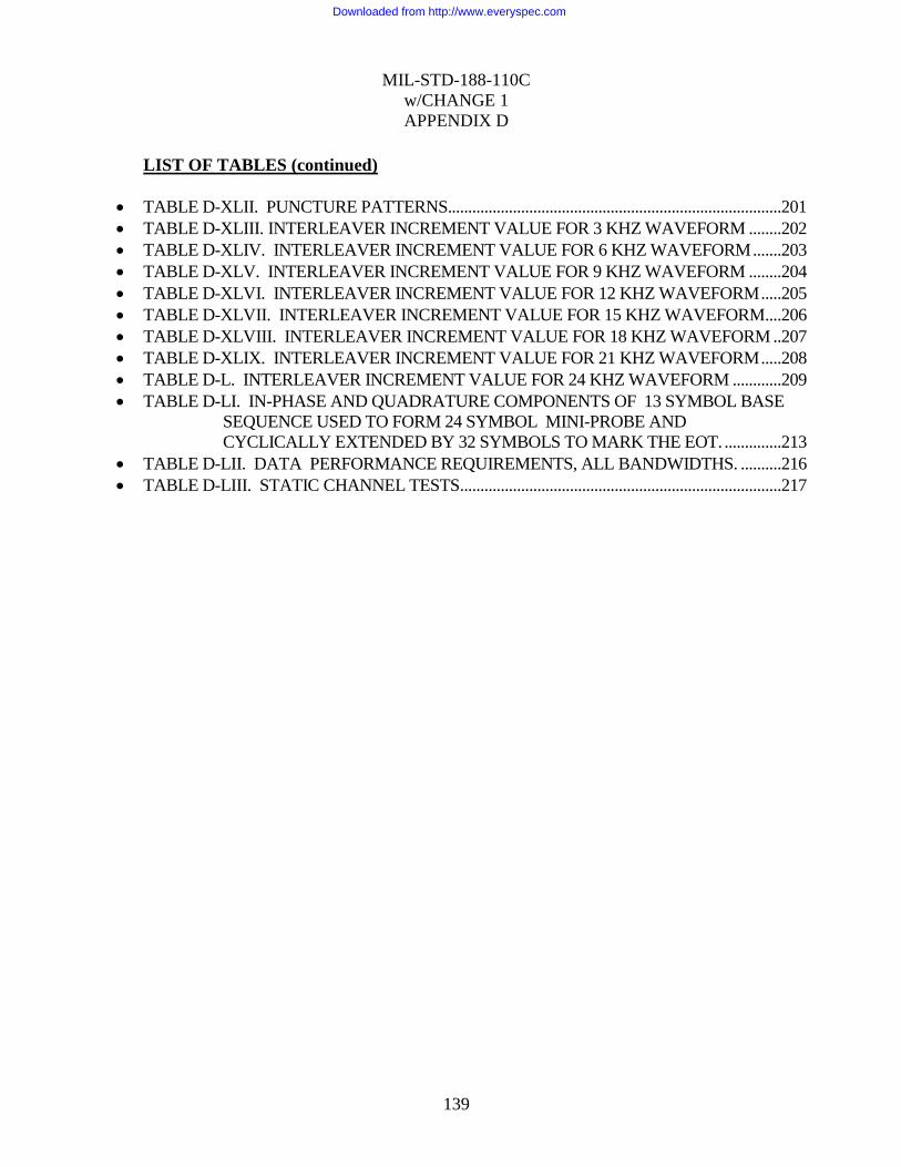
MIL-STD-188-110C
w/CHANGE 1
APPENDIX D
139
LIST OF TABLES (continued)
TABLE D-XLII. PUNCTURE PATTERNS..................................................................................201
TABLE D-XLIII. INTERLEAVER INCREMENT VALUE FOR 3 KHZ WAVEFORM ........202
TABLE D-XLIV. INTERLEAVER INCREMENT VALUE FOR 6 KHZ WAVEFORM .......203
TABLE D-XLV. INTERLEAVER INCREMENT VALUE FOR 9 KHZ WAVEFORM ........204
TABLE D-XLVI. INTERLEAVER INCREMENT VALUE FOR 12 KHZ WAVEFORM .....205
TABLE D-XLVII. INTERLEAVER INCREMENT VALUE FOR 15 KHZ WAVEFORM ....206
TABLE D-XLVIII. INTERLEAVER INCREMENT VALUE FOR 18 KHZ WAVEFORM ..207
TABLE D-XLIX. INTERLEAVER INCREMENT VALUE FOR 21 KHZ WAVEFORM .....208
TABLE D-L. INTERLEAVER INCREMENT VALUE FOR 24 KHZ WAVEFORM ............209
TABLE D-LI. IN-PHASE AND QUADRATURE COMPONENTS OF 13 SYMBOL BASE
SEQUENCE USED TO FORM 24 SYMBOL MINI-PROBE AND
CYCLICALLY EXTENDED BY 32 SYMBOLS TO MARK THE EOT. ..............213
TABLE D-LII. DATA PERFORMANCE REQUIREMENTS, ALL BANDWIDTHS. ..........216
TABLE D-LIII. STATIC CHANNEL TESTS ...............................................................................217
Downloaded from http://www.everyspec.com

MIL-STD-188-110C
w/CHANGE 1
APPENDIX D
140
D.1 SCOPE
D.1.1 Scope.
This appendix describes the HF data modem waveforms for use with single contiguous
bandwidths from 3 KHz to 24 KHz.
D.1.2 Applicability.
This appendix is a non-mandatory part of MIL-STD-188-110C; however, when data is to be
communicated in single contiguous HF radio bandwidths greater than 3 kHz, up to 24 kHz, the
waveforms employed shall be in accordance with this appendix.
D.2 APPLICABLE DOCUMENTS
This section is not applicable to this appendix.
D.3 DEFINITIONS
D.3.1 Abbreviations and acronyms.
Abbreviations and acronyms used in this appendix are defined below. Also see section 3 of
this document.
WBHF Wide Band High Frequency (radio)
Downloaded from http://www.everyspec.com
MIL-STD-188-110C
w/CHANGE 1
APPENDIX D
141
D.4 GENERAL REQUIREMENTS
This appendix presents a family of wideband high-frequency radio (WBHF) modem
waveforms and coding specifications for bandwidths of 3, 6, 9, 12, 15, 18, 21, and 24 kHz.
Data rates of 75 through 120,000 bps are supported. The single-tone waveforms specified in
this appendix use modulation techniques similar to those found in Appendix C of this standard
in order to achieve the required data rates. A block interleaver is used to obtain 4 interleaving
lengths ranging from approximately 0.12 s to 10.24 s. Various code rates are implemented
based on a constraint length 7 or a constraint length 9 convolutional code. Various puncturing
and repeat coding schemes are utilized to achieve a family of code rates from 1/16 up to 9/10.
The full-tail-biting approach is used to produce block codes from this convolutional code that
are the same length as the interleaver. Since the minimum interleaver length spans
approximately 120ms, there is no option of zero interleaving, since the time delays would not
be reduced.
The waveform data rate, encoder constraint length and interleaver settings are explicitly
transmitted as a part of the initial preamble of the waveform. This “autobaud” feature is critical
in developing an efficient (ARQ) protocol for high frequency (HF) channels. The receive
modem is required to be able to determine the data rate, encoder constraint length and
interleaver setting during the reception of the preamble.
For broadcast applications, the receive modem is required to know the bandwidth, data rate,
encoder constraint length and interleaver setting in order to acquire the waveform without the
initial preamble.
D.4.1 WBHF Block 1 Requirements
A subset of the requirements of this appendix when implemented only for 3 kHz is termed the
WBHF Block 1 capability. A Block 1 WBHF modem shall implement all of the following:
Waveforms 0 through 13 for bandwidth of 3 kHz (see Table D-II).
Constraint length 7 convolutional coding
and shall meet the Performance Requirements in D.6 for those waveforms.
D.4.2 WBHF Block 2 Requirements
The same subset of the requirements, but offered at 3, 6, 9, and 12 kHz, is termed the WBHF
Block 2 capability. A Block 2 WBHF modem shall implement all of the following:
Waveforms 0 through 12 for bandwidth of 3, 6, 9, and 12 kHz, and waveform 13 for 3
kHz only (see Table D-II).
Constraint length 7 convolutional coding
and shall meet the Performance Requirements in D.6 for those waveforms.
D.4.3 WBHF Block 3 Requirements
A Block 3 WBHF modem shall implement all of the Detailed Requirements in D.5 and all of
the Performance Requirements in D.6 in this appendix.
Downloaded from http://www.everyspec.com
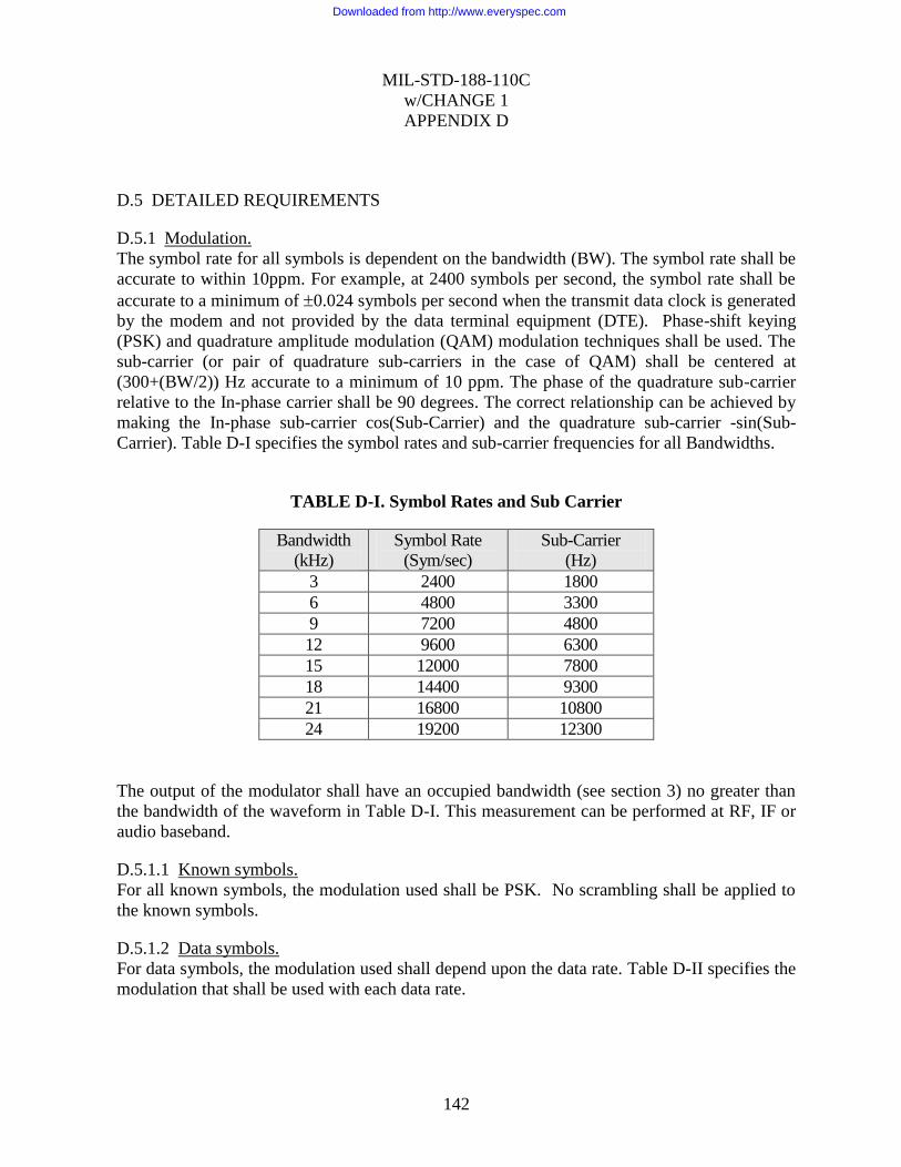
MIL-STD-188-110C
w/CHANGE 1
APPENDIX D
142
D.5 DETAILED REQUIREMENTS
D.5.1 Modulation.
The symbol rate for all symbols is dependent on the bandwidth (BW). The symbol rate shall be
accurate to within 10ppm. For example, at 2400 symbols per second, the symbol rate shall be
accurate to a minimum of 0.024 symbols per second when the transmit data clock is generated
by the modem and not provided by the data terminal equipment (DTE). Phase-shift keying
(PSK) and quadrature amplitude modulation (QAM) modulation techniques shall be used. The
sub-carrier (or pair of quadrature sub-carriers in the case of QAM) shall be centered at
(300+(BW/2)) Hz accurate to a minimum of 10 ppm. The phase of the quadrature sub-carrier
relative to the In-phase carrier shall be 90 degrees. The correct relationship can be achieved by
making the In-phase sub-carrier cos(Sub-Carrier) and the quadrature sub-carrier -sin(Sub-
Carrier). Table D-I specifies the symbol rates and sub-carrier frequencies for all Bandwidths.
TABLE D-I. Symbol Rates and Sub Carrier
Bandwidth
(kHz)
Symbol Rate
(Sym/sec)
Sub-Carrier
(Hz)
3 2400 1800
6 4800 3300
9 7200 4800
12 9600 6300
15 12000 7800
18 14400 9300
21 16800 10800
24 19200 12300
The output of the modulator shall have an occupied bandwidth (see section 3) no greater than
the bandwidth of the waveform in Table D-I. This measurement can be performed at RF, IF or
audio baseband.
D.5.1.1 Known symbols.
For all known symbols, the modulation used shall be PSK. No scrambling shall be applied to
the known symbols.
D.5.1.2 Data symbols.
For data symbols, the modulation used shall depend upon the data rate. Table D-II specifies the
modulation that shall be used with each data rate.
Downloaded from http://www.everyspec.com
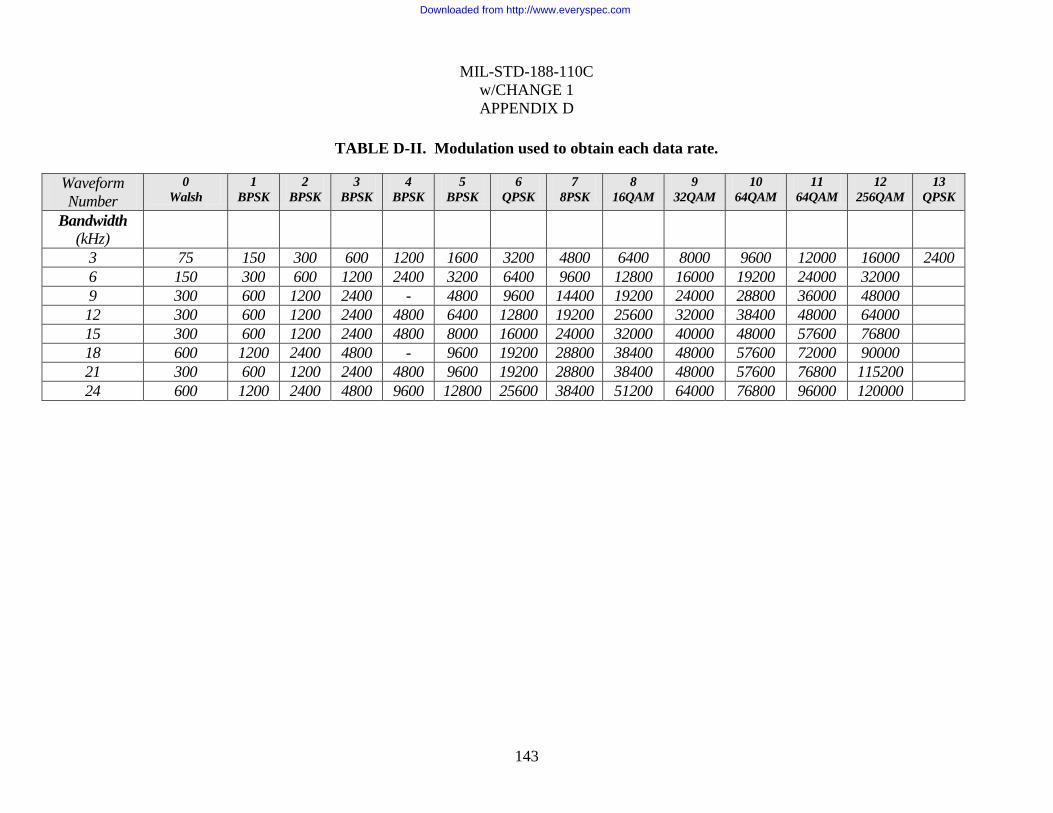
MIL-STD-188-110C
w/CHANGE 1
APPENDIX D
143
TABLE D-II. Modulation used to obtain each data rate.
Waveform
Number
0
Walsh
1
BPSK
2
BPSK
3
BPSK
4
BPSK
5
BPSK
6
QPSK
7
8PSK
8
16QAM
9
32QAM
10
64QAM
11
64QAM
12
256QAM
13
QPSK
Bandwidth (kHz)
3 75 150 300 600 1200 1600 3200 4800 6400 8000 9600 12000 16000 2400
6 150 300 600 1200 2400 3200 6400 9600 12800 16000 19200 24000 32000
9 300 600 1200 2400 - 4800 9600 14400 19200 24000 28800 36000 48000
12 300 600 1200 2400 4800 6400 12800 19200 25600 32000 38400 48000 64000
15 300 600 1200 2400 4800 8000 16000 24000 32000 40000 48000 57600 76800
18 600 1200 2400 4800 - 9600 19200 28800 38400 48000 57600 72000 90000
21 300 600 1200 2400 4800 9600 19200 28800 38400 48000 57600 76800 115200
24 600 1200 2400 4800 9600 12800 25600 38400 51200 64000 76800 96000 120000
Downloaded from http://www.everyspec.com

MIL-STD-188-110C
w/CHANGE 1
APPENDIX D
144
The waveforms utilizing binary phase-shift keying BPSK, quadrature phase-shift keying
(QPSK), and eight-ary phase-shift keying (8PSK) constellations are scrambled to appear, on-
air, as an 8PSK constellation. The scrambling serves a secondary purpose of randomizing the
on air waveform in the presence of a fixed user data stream. The 16QAM and 32QAM
constellations use multiple PSK rings to maintain good peak-to-average ratios, and the 64QAM
constellation is a variation of the standard square QAM constellation, which has been modified
to improve the peak-to-average ratio. The 256 QAM constellation is better than the standard 16
x 16 square constellation and achieves superior peak-to-average without sacrificing the very
good pseudo-Gray code properties of the square constellation. An interesting feature of the
constellation is the slight displacement of the 2 center-top and center-bottom constellation
points to protect constellation points with larger Hamming distances by increasing the signal-
space distance.
D.5.1.2.1 PSK data symbols.
For the PSK constellations, a distinction is made between the data bits and the symbol number
for the purposes of scrambling the BPSK and QPSK modulations to appear as 8PSK, on-air.
Scrambling is applied as a modulo 8 addition of a scrambling sequence to the 8PSK symbol
number. Transcoding is an operation that links a symbol to be transmitted to a group of data
bits.
D.5.1.2.1.1 BPSK symbol mapping.
For the waveforms utilizing binary phase-shift keying BPSK, transcoding shall be achieved by
linking one of the symbols specified in Table D-VI to a single data bits (bit) as shown in Table
D-III.
TABLE D-III. Transcoding for BPSK.
bit Symbol
0 0
1 4
D.5.1.2.1.2 QPSK symbol mapping.
For the waveforms utilizing quadrature phase-shift keying QPSK, transcoding shall be achieved
by linking one of the symbols specified in Table D-VI to a set of two consecutive data bits
(dibit) as shown in Table D-IV. In this Table, the leftmost bit of the dibit shall be the older bit;
i.e., fetched from the interleaver before the rightmost bit.
Downloaded from http://www.everyspec.com
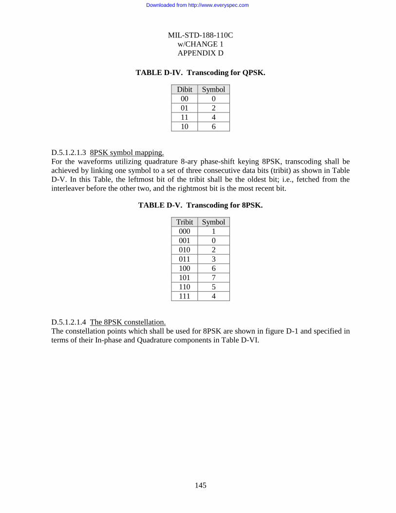
MIL-STD-188-110C
w/CHANGE 1
APPENDIX D
145
TABLE D-IV. Transcoding for QPSK.
Dibit Symbol
00 0
01 2
11 4
10 6
D.5.1.2.1.3 8PSK symbol mapping.
For the waveforms utilizing quadrature 8-ary phase-shift keying 8PSK, transcoding shall be
achieved by linking one symbol to a set of three consecutive data bits (tribit) as shown in Table
D-V. In this Table, the leftmost bit of the tribit shall be the oldest bit; i.e., fetched from the
interleaver before the other two, and the rightmost bit is the most recent bit.
TABLE D-V. Transcoding for 8PSK.
Tribit Symbol
000 1
001 0
010 2
011 3
100 6
101 7
110 5
111 4
D.5.1.2.1.4 The 8PSK constellation.
The constellation points which shall be used for 8PSK are shown in figure D-1 and specified in
terms of their In-phase and Quadrature components in Table D-VI.
Downloaded from http://www.everyspec.com

MIL-STD-188-110C
w/CHANGE 1
APPENDIX D
146
TABLE D-VI. 8PSK symbol mapping.
Symbol
Number
Phase In-Phase Quadrature
0 0 1.000000 0.000000
1 /4 0.707107 0.707107
2 /2 0.000000 1.000000
3 3/4 -0.707107 0.707107
4 -1.000000 0.000000
5 5/4 -0.707107 -0.707107
6 3/2 0.0000000 -1.000000
7 7/4 0.707107 -0.707107
Note that the complex symbol values = exp[jn/4] where n is the symbol number.
Symbol 0
Symbol 1
Symbol 2
Symbol 3
Symbol 4
Symbol 5
Symbol 6
Symbol 7
FIGURE D-1. 8PSK signal constellation and symbol mapping.
Downloaded from http://www.everyspec.com

MIL-STD-188-110C
w/CHANGE 1
APPENDIX D
147
D.5.1.2.2 QAM data symbols.
For the QAM constellations, no distinction is made between the number formed directly from
the data bits and the symbol number. Each set of 4 bits (16QAM), 5 bits (32QAM), 6 bits
(64QAM), or 8 bits (256QAM) is mapped directly to a QAM symbol. For example, the four bit
grouping 0111 would map to symbol 7 in the 16QAM constellation while the 6 bits 100011
would map to symbol 35 in the 64QAM constellation. Again, in each case the leftmost bit shall
be the oldest bit, i.e. fetched from the interleaver before the other bits, and the rightmost bit is
the most recent bit. The mapping of bits to symbols for the QAM constellations has been
selected to minimize the number of bit errors incurred when errors involve adjacent signaling
points in the constellation.
D.5.1.2.2.1 The 16 QAM constellation.
The constellation points which shall be used for 16QAM are shown in figure D-2 and specified
in terms of their In-phase and Quadrature components in Table D-VII. As can be seen in the
figure, the 16 QAM constellation is comprised of two PSK rings: a 4 PSK inner ring and a 12
PSK outer ring.
-1
1
-1 1
16 Point Constellation
FIGURE D-2. 16QAM Signaling Constellation.
Downloaded from http://www.everyspec.com
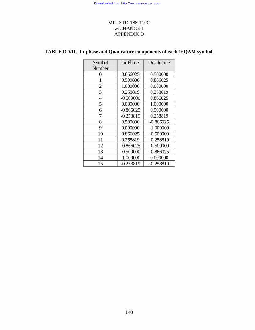
MIL-STD-188-110C
w/CHANGE 1
APPENDIX D
148
TABLE D-VII. In-phase and Quadrature components of each 16QAM symbol.
Symbol
Number
In-Phase Quadrature
0 0.866025 0.500000
1 0.500000 0.866025
2 1.000000 0.000000
3 0.258819 0.258819
4 -0.500000 0.866025
5 0.000000 1.000000
6 -0.866025 0.500000
7 -0.258819 0.258819
8 0.500000 -0.866025
9 0.000000 -1.000000
10 0.866025 -0.500000
11 0.258819 -0.258819
12 -0.866025 -0.500000
13 -0.500000 -0.866025
14 -1.000000 0.000000
15 -0.258819 -0.258819
Downloaded from http://www.everyspec.com
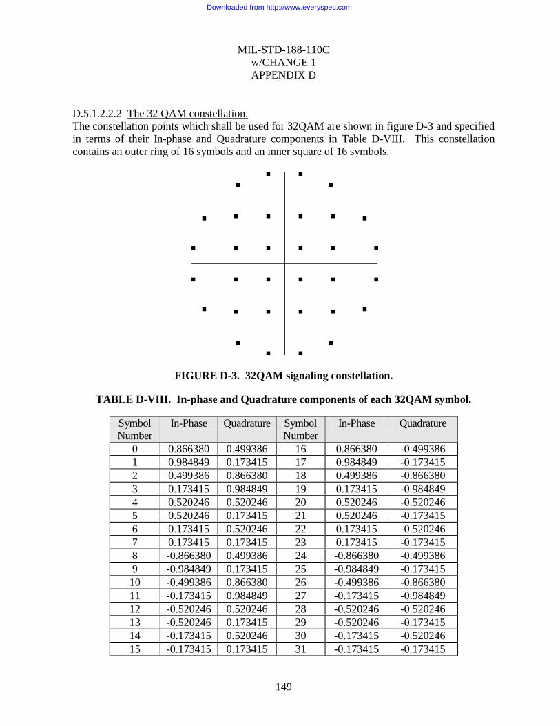
MIL-STD-188-110C
w/CHANGE 1
APPENDIX D
149
D.5.1.2.2.2 The 32 QAM constellation.
The constellation points which shall be used for 32QAM are shown in figure D-3 and specified
in terms of their In-phase and Quadrature components in Table D-VIII. This constellation
contains an outer ring of 16 symbols and an inner square of 16 symbols.
FIGURE D-3. 32QAM signaling constellation.
TABLE D-VIII. In-phase and Quadrature components of each 32QAM symbol.
Symbol
Number
In-Phase Quadrature Symbol
Number
In-Phase Quadrature
0 0.866380 0.499386 16 0.866380 -0.499386
1 0.984849 0.173415 17 0.984849 -0.173415
2 0.499386 0.866380 18 0.499386 -0.866380
3 0.173415 0.984849 19 0.173415 -0.984849
4 0.520246 0.520246 20 0.520246 -0.520246
5 0.520246 0.173415 21 0.520246 -0.173415
6 0.173415 0.520246 22 0.173415 -0.520246
7 0.173415 0.173415 23 0.173415 -0.173415
8 -0.866380 0.499386 24 -0.866380 -0.499386
9 -0.984849 0.173415 25 -0.984849 -0.173415
10 -0.499386 0.866380 26 -0.499386 -0.866380
11 -0.173415 0.984849 27 -0.173415 -0.984849
12 -0.520246 0.520246 28 -0.520246 -0.520246
13 -0.520246 0.173415 29 -0.520246 -0.173415
14 -0.173415 0.520246 30 -0.173415 -0.520246
15 -0.173415 0.173415 31 -0.173415 -0.173415
Downloaded from http://www.everyspec.com
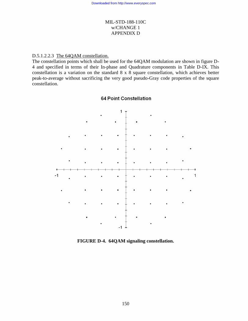
MIL-STD-188-110C
w/CHANGE 1
APPENDIX D
150
D.5.1.2.2.3 The 64QAM constellation.
The constellation points which shall be used for the 64QAM modulation are shown in figure D-
4 and specified in terms of their In-phase and Quadrature components in Table D-IX. This
constellation is a variation on the standard 8 x 8 square constellation, which achieves better
peak-to-average without sacrificing the very good pseudo-Gray code properties of the square
constellation.
FIGURE D-4. 64QAM signaling constellation.
Downloaded from http://www.everyspec.com

MIL-STD-188-110C
w/CHANGE 1
APPENDIX D
151
TABLE D-IX. In-phase and Quadrature components of each 64QAM symbol.
Symbol
Number
In-Phase Quadrature Symbol
Number
In-Phase Quadrature
0 1.000000 0.000000 32 0.000000 1.000000
1 0.822878 0.568218 33 -0.822878 0.568218
2 0.821137 0.152996 34 -0.821137 0.152996
3 0.932897 0.360142 35 -0.932897 0.360142
4 0.000000 -1.000000 36 -1.000000 0.000000
5 0.822878 -0.568218 37 -0.822878 -0.568218
6 0.821137 -0.152996 38 -0.821137 -0.152996
7 0.932897 -0.360142 39 -0.932897 -0.360142
8 0.568218 0.822878 40 -0.568218 0.822878
9 0.588429 0.588429 41 -0.588429 0.588429
10 0.588429 0.117686 42 -0.588429 0.117686
11 0.588429 0.353057 43 -0.588429 0.353057
12 0.568218 -0.822878 44 -0.568218 -0.822878
13 0.588429 -0.588429 45 -0.588429 -0.588429
14 0.588429 -0.117686 46 -0.588429 -0.117686
15 0.588429 -0.353057 47 -0.588429 -0.353057
16 0.152996 0.821137 48 -0.152996 0.821137
17 0.117686 0.588429 49 -0.117686 0.588429
18 0.117686 0.117686 50 -0.117686 0.117686
19 0.117686 0.353057 51 -0.117686 0.353057
20 0.152996 -0.821137 52 -0.152996 -0.821137
21 0.117686 -0.588429 53 -0.117686 -0.588429
22 0.117686 -0.117686 54 -0.117686 -0.117686
23 0.117686 -0.353057 55 -0.117686 -0.353057
24 0.360142 0.932897 56 -0.360142 0.932897
25 0.353057 0.588429 57 -0.353057 0.588429
26 0.353057 0.117686 58 -0.353057 0.117686
27 0.353057 0.353057 59 -0.353057 0.353057
28 0.360142 -0.932897 60 -0.360142 -0.932897
29 0.353057 -0.588429 61 -0.353057 -0.588429
30 0.353057 -0.117686 62 -0.353057 -0.117686
31 0.353057 -0.353057 63 -0.353057 -0.353057
Downloaded from http://www.everyspec.com

MIL-STD-188-110C
w/CHANGE 1
APPENDIX D
152
D.5.1.2.2.4 The 256QAM constellation.
The constellation points that shall be used for the 256QAM modulation are shown in Figure D-
5 and specified in terms of their In-phase and Quadrature components in Table D-X. This
constellation is better than the standard 16 x 16 square constellation and achieves superior
peak-to-average without sacrificing the very good pseudo-Gray code properties of the square
constellation. An interesting feature of the constellation is the slight displacement of the 2
center-top and center-bottom constellation points to protect constellation points with larger
Hamming distances by increasing the signal-space distance.
FIGURE D-5. 256QAM signaling constellation.
Downloaded from http://www.everyspec.com
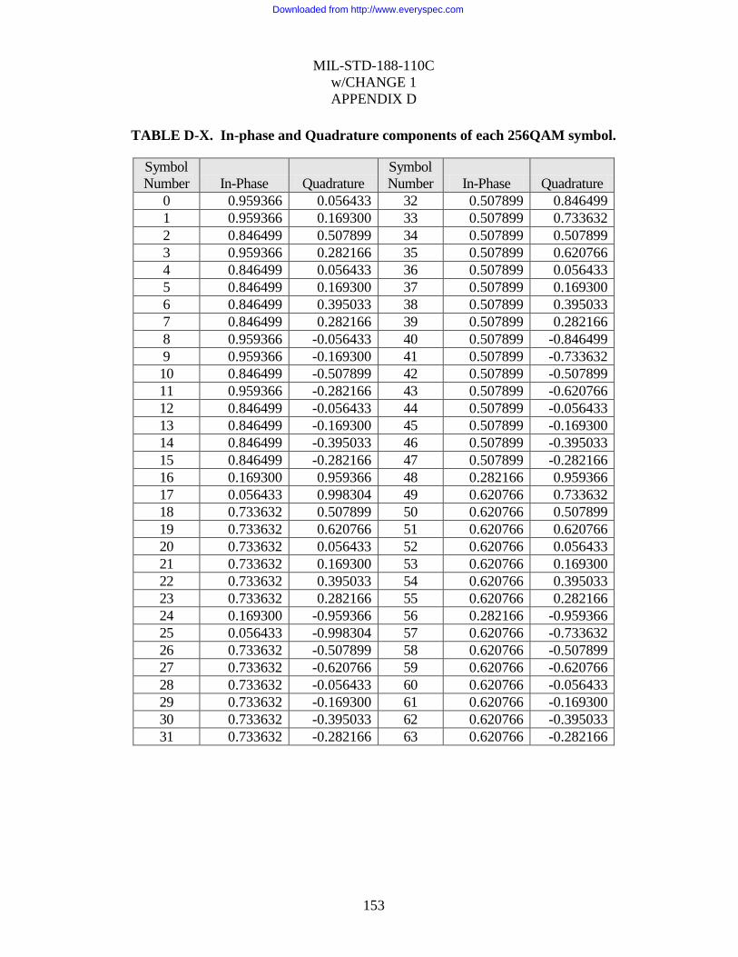
MIL-STD-188-110C
w/CHANGE 1
APPENDIX D
153
TABLE D-X. In-phase and Quadrature components of each 256QAM symbol.
Symbol
Number In-Phase Quadrature Symbol
Number In-Phase Quadrature
0 0.959366 0.056433 32 0.507899 0.846499
1 0.959366 0.169300 33 0.507899 0.733632
2 0.846499 0.507899 34 0.507899 0.507899
3 0.959366 0.282166 35 0.507899 0.620766
4 0.846499 0.056433 36 0.507899 0.056433
5 0.846499 0.169300 37 0.507899 0.169300
6 0.846499 0.395033 38 0.507899 0.395033
7 0.846499 0.282166 39 0.507899 0.282166
8 0.959366 -0.056433 40 0.507899 -0.846499
9 0.959366 -0.169300 41 0.507899 -0.733632
10 0.846499 -0.507899 42 0.507899 -0.507899
11 0.959366 -0.282166 43 0.507899 -0.620766
12 0.846499 -0.056433 44 0.507899 -0.056433
13 0.846499 -0.169300 45 0.507899 -0.169300
14 0.846499 -0.395033 46 0.507899 -0.395033
15 0.846499 -0.282166 47 0.507899 -0.282166
16 0.169300 0.959366 48 0.282166 0.959366
17 0.056433 0.998304 49 0.620766 0.733632
18 0.733632 0.507899 50 0.620766 0.507899
19 0.733632 0.620766 51 0.620766 0.620766
20 0.733632 0.056433 52 0.620766 0.056433
21 0.733632 0.169300 53 0.620766 0.169300
22 0.733632 0.395033 54 0.620766 0.395033
23 0.733632 0.282166 55 0.620766 0.282166
24 0.169300 -0.959366 56 0.282166 -0.959366
25 0.056433 -0.998304 57 0.620766 -0.733632
26 0.733632 -0.507899 58 0.620766 -0.507899
27 0.733632 -0.620766 59 0.620766 -0.620766
28 0.733632 -0.056433 60 0.620766 -0.056433
29 0.733632 -0.169300 61 0.620766 -0.169300
30 0.733632 -0.395033 62 0.620766 -0.395033
31 0.733632 -0.282166 63 0.620766 -0.282166
Downloaded from http://www.everyspec.com
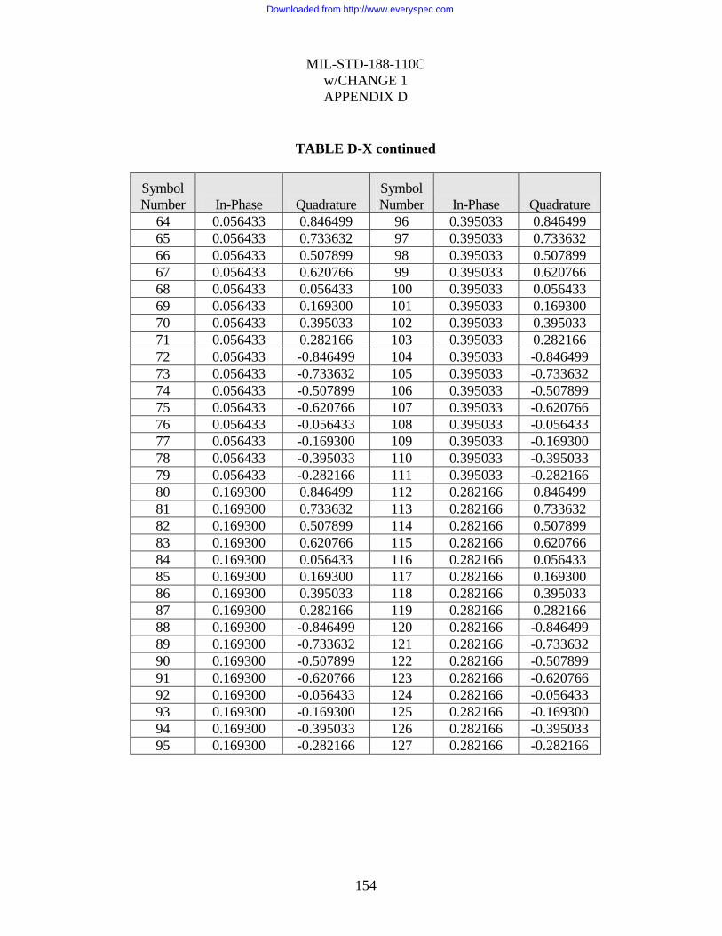
MIL-STD-188-110C
w/CHANGE 1
APPENDIX D
154
TABLE D-X continued
Symbol
Number In-Phase Quadrature Symbol
Number In-Phase Quadrature
64 0.056433 0.846499 96 0.395033 0.846499
65 0.056433 0.733632 97 0.395033 0.733632
66 0.056433 0.507899 98 0.395033 0.507899
67 0.056433 0.620766 99 0.395033 0.620766
68 0.056433 0.056433 100 0.395033 0.056433
69 0.056433 0.169300 101 0.395033 0.169300
70 0.056433 0.395033 102 0.395033 0.395033
71 0.056433 0.282166 103 0.395033 0.282166
72 0.056433 -0.846499 104 0.395033 -0.846499
73 0.056433 -0.733632 105 0.395033 -0.733632
74 0.056433 -0.507899 106 0.395033 -0.507899
75 0.056433 -0.620766 107 0.395033 -0.620766
76 0.056433 -0.056433 108 0.395033 -0.056433
77 0.056433 -0.169300 109 0.395033 -0.169300
78 0.056433 -0.395033 110 0.395033 -0.395033
79 0.056433 -0.282166 111 0.395033 -0.282166
80 0.169300 0.846499 112 0.282166 0.846499
81 0.169300 0.733632 113 0.282166 0.733632
82 0.169300 0.507899 114 0.282166 0.507899
83 0.169300 0.620766 115 0.282166 0.620766
84 0.169300 0.056433 116 0.282166 0.056433
85 0.169300 0.169300 117 0.282166 0.169300
86 0.169300 0.395033 118 0.282166 0.395033
87 0.169300 0.282166 119 0.282166 0.282166
88 0.169300 -0.846499 120 0.282166 -0.846499
89 0.169300 -0.733632 121 0.282166 -0.733632
90 0.169300 -0.507899 122 0.282166 -0.507899
91 0.169300 -0.620766 123 0.282166 -0.620766
92 0.169300 -0.056433 124 0.282166 -0.056433
93 0.169300 -0.169300 125 0.282166 -0.169300
94 0.169300 -0.395033 126 0.282166 -0.395033
95 0.169300 -0.282166 127 0.282166 -0.282166
Downloaded from http://www.everyspec.com

MIL-STD-188-110C
w/CHANGE 1
APPENDIX D
155
TABLE D-X continued
Symbol
Number In-Phase Quadrature Symbol
Number In-Phase Quadrature
128 -0.959366 0.056433 160 -0.507899 0.846499
129 -0.959366 0.169300 161 -0.507899 0.733632
130 -0.846499 0.507899 162 -0.507899 0.507899
131 -0.959366 0.282166 163 -0.507899 0.620766
132 -0.846499 0.056433 164 -0.507899 0.056433
133 -0.846499 0.169300 165 -0.507899 0.169300
134 -0.846499 0.395033 166 -0.507899 0.395033
135 -0.846499 0.282166 167 -0.507899 0.282166
136 -0.959366 -0.056433 168 -0.507899 -0.846499
137 -0.959366 -0.169300 169 -0.507899 -0.733632
138 -0.846499 -0.507899 170 -0.507899 -0.507899
139 -0.959366 -0.282166 171 -0.507899 -0.620766
140 -0.846499 -0.056433 172 -0.507899 -0.056433
141 -0.846499 -0.169300 173 -0.507899 -0.169300
142 -0.846499 -0.395033 174 -0.507899 -0.395033
143 -0.846499 -0.282166 175 -0.507899 -0.282166
144 -0.169300 0.959366 176 -0.282166 0.959366
145 -0.056433 0.998304 177 -0.620766 0.733632
146 -0.733632 0.507899 178 -0.620766 0.507899
147 -0.733632 0.620766 179 -0.620766 0.620766
148 -0.733632 0.056433 180 -0.620766 0.056433
149 -0.733632 0.169300 181 -0.620766 0.169300
150 -0.733632 0.395033 182 -0.620766 0.395033
151 -0.733632 0.282166 183 -0.620766 0.282166
152 -0.169300 -0.959366 184 -0.282166 -0.959366
153 -0.056433 -0.998304 185 -0.620766 -0.733632
154 -0.733632 -0.507899 186 -0.620766 -0.507899
155 -0.733632 -0.620766 187 -0.620766 -0.620766
156 -0.733632 -0.056433 188 -0.620766 -0.056433
157 -0.733632 -0.169300 189 -0.620766 -0.169300
158 -0.733632 -0.395033 190 -0.620766 -0.395033
159 -0.733632 -0.282166 191 -0.620766 -0.282166
Downloaded from http://www.everyspec.com
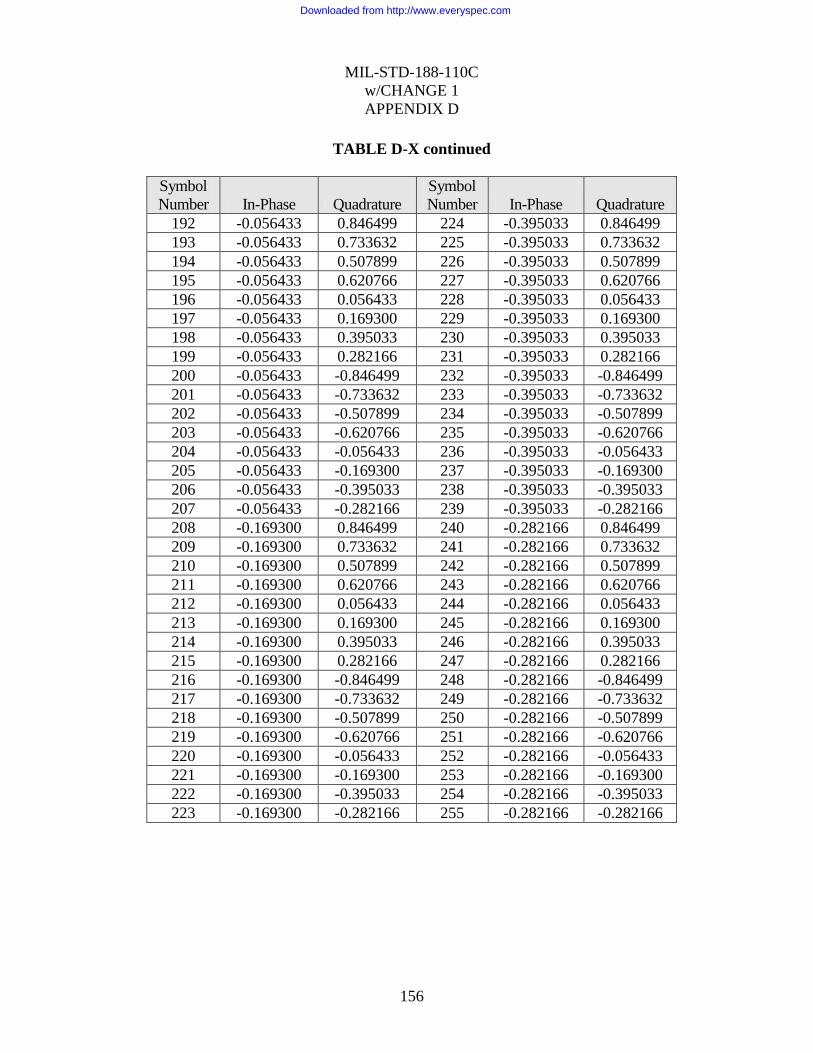
MIL-STD-188-110C
w/CHANGE 1
APPENDIX D
156
TABLE D-X continued
Symbol
Number In-Phase Quadrature Symbol
Number In-Phase Quadrature
192 -0.056433 0.846499 224 -0.395033 0.846499
193 -0.056433 0.733632 225 -0.395033 0.733632
194 -0.056433 0.507899 226 -0.395033 0.507899
195 -0.056433 0.620766 227 -0.395033 0.620766
196 -0.056433 0.056433 228 -0.395033 0.056433
197 -0.056433 0.169300 229 -0.395033 0.169300
198 -0.056433 0.395033 230 -0.395033 0.395033
199 -0.056433 0.282166 231 -0.395033 0.282166
200 -0.056433 -0.846499 232 -0.395033 -0.846499
201 -0.056433 -0.733632 233 -0.395033 -0.733632
202 -0.056433 -0.507899 234 -0.395033 -0.507899
203 -0.056433 -0.620766 235 -0.395033 -0.620766
204 -0.056433 -0.056433 236 -0.395033 -0.056433
205 -0.056433 -0.169300 237 -0.395033 -0.169300
206 -0.056433 -0.395033 238 -0.395033 -0.395033
207 -0.056433 -0.282166 239 -0.395033 -0.282166
208 -0.169300 0.846499 240 -0.282166 0.846499
209 -0.169300 0.733632 241 -0.282166 0.733632
210 -0.169300 0.507899 242 -0.282166 0.507899
211 -0.169300 0.620766 243 -0.282166 0.620766
212 -0.169300 0.056433 244 -0.282166 0.056433
213 -0.169300 0.169300 245 -0.282166 0.169300
214 -0.169300 0.395033 246 -0.282166 0.395033
215 -0.169300 0.282166 247 -0.282166 0.282166
216 -0.169300 -0.846499 248 -0.282166 -0.846499
217 -0.169300 -0.733632 249 -0.282166 -0.733632
218 -0.169300 -0.507899 250 -0.282166 -0.507899
219 -0.169300 -0.620766 251 -0.282166 -0.620766
220 -0.169300 -0.056433 252 -0.282166 -0.056433
221 -0.169300 -0.169300 253 -0.282166 -0.169300
222 -0.169300 -0.395033 254 -0.282166 -0.395033
223 -0.169300 -0.282166 255 -0.282166 -0.282166
Downloaded from http://www.everyspec.com

MIL-STD-188-110C
w/CHANGE 1
APPENDIX D
157
D.5.1.2.3 Walsh Orthogonal Modulation.
Waveform ID 0 utilizes a different modulation technique, Walsh Orthogonal Modulation. For
each pair of coded and interleaved data bits, the method produces a 32 symbol repeated Walsh
sequence. The Walsh Orthogonal Modulation is accomplished by taking each pair of bits, or di-
bit, and selecting a corresponding Walsh Sequence.
Di-bit Walsh Sequence
00 0000
01 0404
10 0044
11 0440
The selected four element Walsh sequence is repeated 8 times to yield a 32 element Walsh
sequence.
For example, if the di-bit is 01, the sequence 0404 is repeated to generate
0, 4, 0, 4, 0, 4, 0, 4, 0, 4, 0, 4, 0, 4, 0, 4, 0, 4, 0, 4, 0, 4, 0, 4, 0, 4, 0, 4, 0, 4, 0, 4
The last di-bit in any interleaver block shall be identified by use of an alternate set of Walsh
sequences, which are repeated 4 times to achieve 32 symbols:
Di-bit
Alternate
Walsh Sequence
00 00004444
01 04044040
10 00444400
11 04404004
The 32-symbol channel symbol shall be produced by an element by element modulo 8 addition
of the repeated Walsh Sequence and the scrambling sequence (see 0).
D.5.1.3 Data scrambling.
Data symbols for Waveforms 1 through 7 and 13 (using BPSK, QPSK, or 8PSK modulation)
shall be scrambled by modulo 8 addition with a scrambling sequence.
The data symbols for Waveforms 8 through 12(16QAM, 32QAM, 64QAM and 256QAM
modulation) shall be scrambled by using an exclusive or (XOR) operation. Sequentially, the
data bits forming each symbol (4 for 16QAM, 5 for 32QAM, 6 for 64QAM and 8 for 256
QAM) shall be XOR‟d with an equal number of bits from the scrambling sequence.
For Waveforms 1 through 13, the scrambling sequence generator polynomial shall be x9 +x4 +1
and the generator shall be initialized to 1 at the start of each data frame. A block diagram of the
scrambling sequence generator is shown in Figure D-6. In this illustration, three output bits are
Downloaded from http://www.everyspec.com
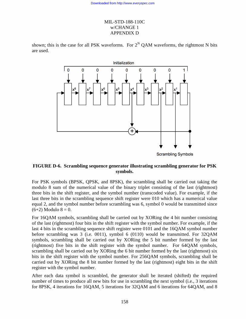
MIL-STD-188-110C
w/CHANGE 1
APPENDIX D
158
shown; this is the case for all PSK waveforms. For 2N QAM waveforms, the rightmost N bits
are used.
FIGURE D-6. Scrambling sequence generator illustrating scrambling generator for PSK
symbols.
For PSK symbols (BPSK, QPSK, and 8PSK), the scrambling shall be carried out taking the
modulo 8 sum of the numerical value of the binary triplet consisting of the last (rightmost)
three bits in the shift register, and the symbol number (transcoded value). For example, if the
last three bits in the scrambling sequence shift register were 010 which has a numerical value
equal 2, and the symbol number before scrambling was 6, symbol 0 would be transmitted since
(6+2) Modulo 8 = 0.
For 16QAM symbols, scrambling shall be carried out by XORing the 4 bit number consisting
of the last (rightmost) four bits in the shift register with the symbol number. For example, if the
last 4 bits in the scrambling sequence shift register were 0101 and the 16QAM symbol number
before scrambling was 3 (i.e. 0011), symbol 6 (0110) would be transmitted. For 32QAM
symbols, scrambling shall be carried out by XORing the 5 bit number formed by the last
(rightmost) five bits in the shift register with the symbol number. For 64QAM symbols,
scrambling shall be carried out by XORing the 6 bit number formed by the last (rightmost) six
bits in the shift register with the symbol number. For 256QAM symbols, scrambling shall be
carried out by XORing the 8 bit number formed by the last (rightmost) eight bits in the shift
register with the symbol number.
After each data symbol is scrambled, the generator shall be iterated (shifted) the required
number of times to produce all new bits for use in scrambling the next symbol (i.e., 3 iterations
for 8PSK, 4 iterations for 16QAM, 5 iterations for 32QAM and 6 iterations for 64QAM, and 8
Downloaded from http://www.everyspec.com

MIL-STD-188-110C
w/CHANGE 1
APPENDIX D
159
iterations for 256QAM). Since the generator is iterated after the bits are used, the first data
symbol of every data frame shall, therefore, be scrambled by the appropriate number of bits
from the initialization value of 00000001.
The length of the scrambling sequence is 511 bits. For a 256 symbol data block with 6 bits per
symbol, this means that the scrambling sequence will be repeated just slightly more than 3
times, although in terms of symbols, there will be no repetition.
D.5.1.4 Waveform ID 0 Walsh Orthogonal Modulation Data scrambling.
For the case of Waveform ID 0, an 8-PSK data scrambling sequence is utilized. This sequence
is generated in a fashion similar to that described above but is based on a longer shift register of
159 bits with a single tap after bit 31. This is an implementation of a Trinomial (159, 31). The
shift register is initialized to the following state:
int bitshift[159] =
{0, 0, 0, 1, 0, 0, 1, 1, 0, 1, 1, 0, 0, 1, 0, 1,
1, 1, 1, 1, 0, 1, 0, 0, 1, 0, 0, 0, 0, 0, 0, 0,
1, 0, 1, 1, 0, 0, 1, 1, 0, 0, 1, 0, 1, 1, 1, 0,
1, 1, 1, 0, 0, 0, 1, 1, 0, 0, 0, 1, 0, 0, 0, 0,
1, 0, 0, 0, 0, 0, 1, 0, 0, 0, 0, 0, 1, 1, 0, 1,
0, 1, 1, 1, 1, 0, 1, 0, 1, 0, 0, 0, 1, 1, 1, 1,
1, 1, 0, 0, 1, 1, 0, 1, 0, 1, 1, 1, 1, 1, 0, 1,
1, 1, 1, 0, 0, 0, 1, 1, 0, 0, 0, 1, 1, 0, 1, 0,
1, 1, 1, 0, 0, 1, 1, 1, 0, 0, 0, 1, 1, 0, 0, 0,
1, 0, 0, 1, 0, 0, 0, 1, 1, 0, 1, 0, 0, 1, 1};
For Waveform ID 0 this implementation is used to generate 256*8 or 2048 values. The shift
register is iterated 16 times between the generation of each 8-PSK symbol.
int tri( void)
{
int bitout, bittap, bitin;
int i,j;
for(j=0;j<16;j++)
{
bitout = bitshift[158];
bittap = bitshift[31];
for(i=158;i>=1;i--) bitshift[i]=bitshift[i-1];
bitin = bitout^bittap;
bitshift[0]=bitin;
}
return (bitshift[2]<<2)+(bitshift[1]<<1)+bitshift[0];
}
Each channel symbol of the WID 0 waveforms is scrambled using 32 chips or symbols of the
scramble sequence, generated as defined above.
Downloaded from http://www.everyspec.com
MIL-STD-188-110C
w/CHANGE 1
APPENDIX D
160
For example, the first 32 symbols of the scramble sequence are
5, 6, 2, 1, 7, 3, 1, 1, 6, 0, 5, 4, 0, 7, 7, 0, 5, 3, 1, 3, 3, 2, 2, 5, 5, 4, 7, 3, 5, 4, 3, 0,
For this example, assume the coded and interleaved data di-bit to be sent is 01; then the
corresponding Walsh sequence 0 4 0 4 is repeated and combined with this scrambling
sequence as shown below:
0, 4, 0, 4, 0, 4, 0, 4, 0, 4, 0, 4, 0, 4, 0, 4, 0, 4, 0, 4, 0, 4, 0, 4, 0, 4, 0, 4, 0, 4, 0, 4
5, 6, 2, 1, 7, 3, 1, 1, 6, 0, 5, 4, 0, 7, 7, 0, 5, 3, 1, 3, 3, 2, 2, 5, 5, 4, 7, 3, 5, 4, 3, 0,
========================================================
5, 2, 2, 5, 7, 7, 1, 5, 6, 4, 5, 0, 0, 3, 7, 4, 5, 7, 1, 7, 3, 6, 2, 1, 5, 0, 7, 7, 5, 0, 3, 4
For the Walsh Orthogonal Modes the sequences are continuously wrapped around the 2048
symbol boundary. The sequence is reset to the initialization value at the interleaver boundary.
D.5.1.5 Modulation filter.
The role of the modulation filter is to spectrally constrain the transmit waveform to within the
specified bandwidth. A square root of raised cosine filter is recommended with a roll off
factor (excess bandwidth) of 35%. Utilizing this filter as both the modem modulation filter and
demodulation filter will maximize the signal to noise ratio and minimize inter-symbol
interference. The combined modulation and demodulation filters will have the following
frequency response (symmetric around 0 Hz):
H(f) = 1 for |f| <= fn – pfn
H(f) = 0.5( 1 – sin(f-fn * PI / 2pfn) for fn – pfn < |f| <= fn + pfn
H(f) = 0 elsewhere
Where:
fn is the Nyquist frequency ( fn = 1 / (2T) = (1 / 2) * SYMBOL RATE = 1200 Hz for
3kHz BW, 9600Hz for 24kHz BW)
p is the roll off factor or excess bandwidth.
The individual modulation and demodulation filters are realized by taking the square root of the
above frequency response.
Downloaded from http://www.everyspec.com
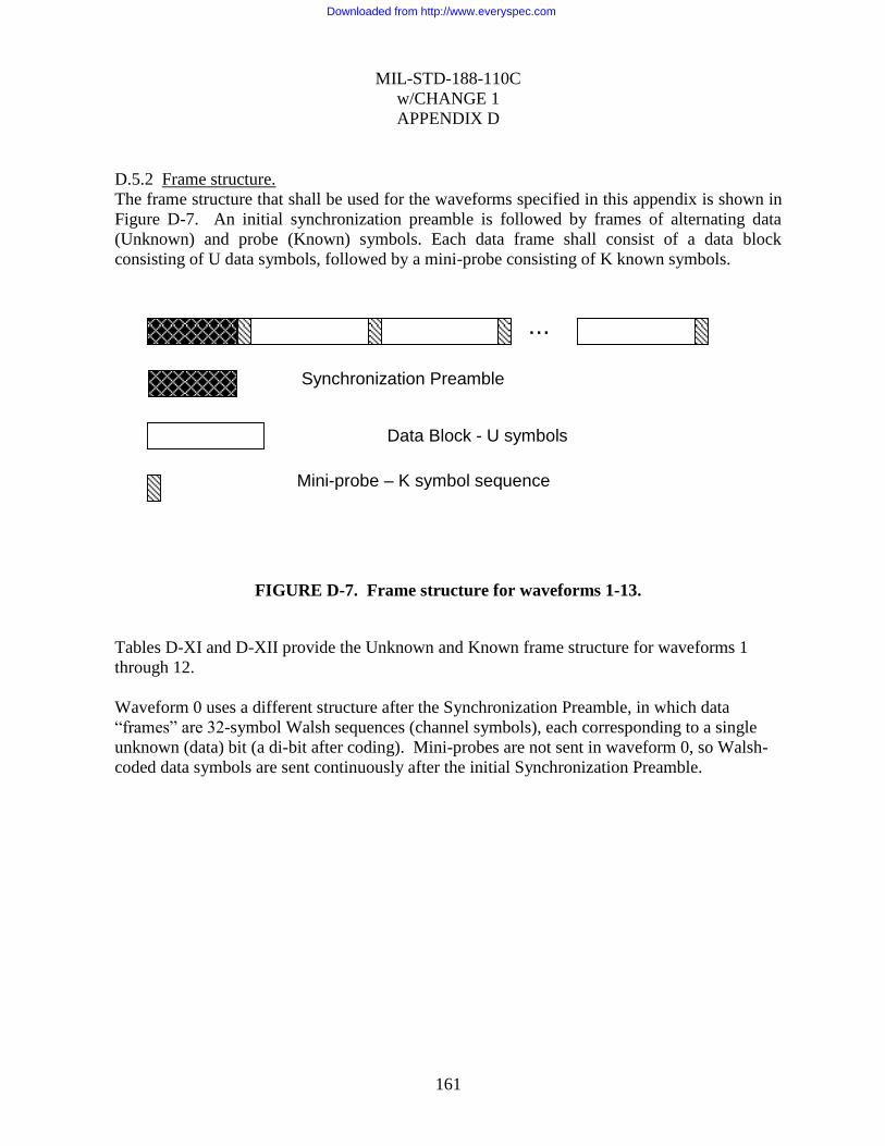
MIL-STD-188-110C
w/CHANGE 1
APPENDIX D
161
D.5.2 Frame structure.
The frame structure that shall be used for the waveforms specified in this appendix is shown in
Figure D-7. An initial synchronization preamble is followed by frames of alternating data
(Unknown) and probe (Known) symbols. Each data frame shall consist of a data block
consisting of U data symbols, followed by a mini-probe consisting of K known symbols.
FIGURE D-7. Frame structure for waveforms 1-13.
Tables D-XI and D-XII provide the Unknown and Known frame structure for waveforms 1
through 12.
Waveform 0 uses a different structure after the Synchronization Preamble, in which data
“frames” are 32-symbol Walsh sequences (channel symbols), each corresponding to a single
unknown (data) bit (a di-bit after coding). Mini-probes are not sent in waveform 0, so Walsh-
coded data symbols are sent continuously after the initial Synchronization Preamble.
...
Synchronization Preamble
Data Block - U symbols
Mini-probe – K symbol sequence
Downloaded from http://www.everyspec.com

MIL-STD-188-110C
w/CHANGE 1
APPENDIX D
162
TABLE D- XI. Number of Unknown (Data) Symbols in Frame
Waveform
Number 0
Walsh
1
BPSK
2
BPSK
3
BPSK
4
BPSK
5
BPSK
6
QPSK
7
8PSK
8
16QAM
9
32QAM
10
64QAM
11
64QAM
12
256QAM
13
QPSK
Bandwidth (kHz)
3 N/A 48 48 96 96 256 256 256 256 256 256 360 360 256
6 N/A 96 96 204 204 544 544 544 544 544 544 540 540
9 N/A 288 288 288 - 768 768 768 768 768 768 1080 1080
12 N/A 192 192 384 384 1024 1024 1024 1024 1024 1024 1080 1080
15 N/A 288 288 288 288 1280 1280 1280 1280 1280 1280 1152 1152
18 N/A 448 448 448 - 1536 1536 1536 1536 1536 1536 1920 1920
21 N/A 320 320 320 320 1344 1344 1344 1344 1344 1344 2560 2560
24 N/A 272 272 816 816 2176 2176 2176 2176 2176 2176 1920 1920
TABLE D- XII. Number of Known Symbols (Mini-Probe) in Frame
Waveform
Number 0
Walsh
1
BPSK
2
BPSK
3
BPSK
4
BPSK
5
BPSK
6
QPSK
7
8PSK
8
16QAM
9
32QAM
10
64QAM
11
64QAM
12
256QAM
13
QPSK
Bandwidth (kHz)
3 N/A 48 48 32 32 32 32 32 32 32 32 24 24 32
6 N/A 96 96 68 68 68 68 68 68 68 68 36 36
9 N/A 144 144 144 - 96 96 96 96 96 96 72 72
12 N/A 192 192 128 128 128 128 128 128 128 128 72 72
15 N/A 192 192 192 192 160 160 160 160 160 160 128 128
18 N/A 224 224 224 - 192 192 192 192 192 192 128 128
21 N/A 240 240 240 240 224 224 224 224 224 224 128 128
24 N/A 272 272 272 272 272 272 272 272 272 272 128 128
Downloaded from http://www.everyspec.com

MIL-STD-188-110C
w/CHANGE 1
APPENDIX D
163
D.5.2.1 Synchronization preamble.
The synchronization preamble is used for rapid initial synchronization and provides time and
frequency alignment. The synchronization preamble shall consist of two main sections, a
transmitter level control (TLC) settling time section, and a synchronization section containing a
repeated preamble super-frame. The preamble super-frame consists of three distinct
subsections, one with a fixed (known) modulation, one to convey a downcount, and one to
convey waveform identification. The superframe shall be repeated M times. The
Synchronization section shall be immediately followed by the modulated data (Figure D-8).
FIGURE D-8. Synchronization preamble structure.
D.5.2.1.1 4-ary Orthogonal Walsh Modulation in the preamble.
4-ary orthogonal Walsh modulation shall be used in the synchronization section of the
preamble. The length of each channel symbol, in chips or symbols, is dependent on the
bandwidth of the modem waveform selected and shall be as given by Table D-XIII.
TABLE D-XIII. Length of Preamble Channel Symbols
Bandwidth
(kHz)
Walsh Sequence
Length in Preamble
3 32
6 64
9 96
12 128
15 160
18 192
21 224
24 256
Downloaded from http://www.everyspec.com
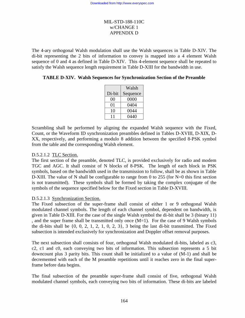
MIL-STD-188-110C
w/CHANGE 1
APPENDIX D
164
The 4-ary orthogonal Walsh modulation shall use the Walsh sequences in Table D-XIV. The
di-bit representing the 2 bits of information to convey is mapped into a 4 element Walsh
sequence of 0 and 4 as defined in Table D-XIV. This 4-element sequence shall be repeated to
satisfy the Walsh sequence length requirement in Table D-XIII for the bandwidth in use.
TABLE D-XIV. Walsh Sequences for Synchronization Section of the Preamble
Di-bit
Walsh
Sequence
00 0000
01 0404
10 0044
11 0440
Scrambling shall be performed by aligning the expanded Walsh sequence with the Fixed,
Count, or the Waveform ID synchronization preambles defined in Tables D-XVIII, D-XIX, D-
XX, respectively, and performing a modulo 8 addition between the specified 8-PSK symbol
from the table and the corresponding Walsh element.
D.5.2.1.2 TLC Section.
The first section of the preamble, denoted TLC, is provided exclusively for radio and modem
TGC and AGC. It shall consist of N blocks of 8-PSK. The length of each block in PSK
symbols, based on the bandwidth used in the transmission to follow, shall be as shown in Table
D-XIII. The value of N shall be configurable to range from 0 to 255 (for N=0 this first section
is not transmitted). These symbols shall be formed by taking the complex conjugate of the
symbols of the sequence specified below for the Fixed section in Table D-XVIII.
D.5.2.1.3 Synchronization Section.
The Fixed subsection of the super-frame shall consist of either 1 or 9 orthogonal Walsh
modulated channel symbols. The length of each channel symbol, dependent on bandwidth, is
given in Table D-XIII. For the case of the single Walsh symbol the di-bit shall be 3 (binary 11)
, and the super frame shall be transmitted only once (M=1). For the case of 9 Walsh symbols
the di-bits shall be {0, 0, 2, 1, 2, 1, 0, 2, 3}, 3 being the last di-bit transmitted. The Fixed
subsection is intended exclusively for synchronization and Doppler offset removal purposes.
The next subsection shall consists of four, orthogonal Walsh modulated di-bits, labeled as c3,
c2, c1 and c0, each conveying two bits of information. This subsection represents a 5 bit
downcount plus 3 parity bits. This count shall be initialized to a value of (M-1) and shall be
decremented with each of the M preamble repetitions until it reaches zero in the final super-
frame before data begins.
The final subsection of the preamble super-frame shall consist of five, orthogonal Walsh
modulated channel symbols, each conveying two bits of information. These di-bits are labeled
Downloaded from http://www.everyspec.com

MIL-STD-188-110C
w/CHANGE 1
APPENDIX D
165
as w4, w3, w2, w1, and w0. These 10 bits represent a Waveform ID consisting of waveform
number, interleaver option, convolutional code length and parity check.
D.5.2.1.3.1 Mapping of the downcount di-bits c3, c2, c1, and c0.
The 5 bit super-frame down count is initialized to M-1 where M is the number of repeats of the
super-frame and can be viewed as a binary number b4b3b2b1b0 where b4 is the MSB and b0 is
the LSB. Bits b7, b6, and b5 shall contain a parity check computed over b4b3b2b1b0 as
follows, where the ^ symbol indicates exclusive-or:
b7 = b1 ^ b2 ^ b3
b6 = b2 ^ b3 ^ b4
b5 = b0 ^ b1 ^ b2
C3 shall contain the two MSBs b7 and b6, b7 being the MSB. C2 shall contain the next two bits
of the count b5 and b4, b5 being the MSB. C1 shall contain the next two bits of the count b3
and b2, b3 being the MSB. C0 shall contain the last two bits of the count b1 and b0, b1 being
the MSB.
D.5.2.1.3.2 Mapping of the Waveform ID di-bits w4, w3, w2, w1, and w0.
The 10 bit waveform ID field consists of 5 di-bits w4, w3, w2, w1, and w0. The 10 bits are
labeled d9 down to d0. W4 contains d9 and d8, where d9 is the MSB, w3 contains d7 and d6,
and so on down to w0 which contains d1 and d0.
The 3 LSBs, d2, d1, and d0, shall contain a 3 bit checksum calculated over d9d8d7d6d5d4d3 as
follows, where the ^ symbol indicates exclusive-or:
d2 = d9 ^ d8 ^ d7
d1 = d7 ^ d6 ^ d5
d0 = d5 ^ d4 ^ d3
Downloaded from http://www.everyspec.com

MIL-STD-188-110C
w/CHANGE 1
APPENDIX D
166
The four bit waveform number, defined in Table D-II for all possible waveform options for a
given bandwidth, shall be mapped into the w4 and w3 di-bits as defined in Table D-XV. The
reserved encodings shall not be sent.
TABLE D-XV. Waveform number mapping.
Waveform
Number
w4
d9 d8
w3
d7 d6
0 0 0 0 0
1 0 0 0 1
2 0 0 1 0
3 0 0 1 1
4 0 1 0 0
5 0 1 0 1
6 0 1 1 0
7 0 1 1 1
8 1 0 0 0
9 1 0 0 1
10 1 0 1 0
11 1 0 1 1
12 1 1 0 0
13 1 1 0 1
(reserved) 1 1 1 0
(reserved) 1 1 1 1
The Interleaver selection shall be mapped to w2 as defined in Table D-XVI.
TABLE D-XVI. Interleaver selection mapping.
Interleaver w2
d5 d4
Ultra Short 0 0
Short 0 1
Medium 1 0
Long 1 1
The convolutional code constraint length shall be mapped into w1 as defined in Table D-XVII.
The lsb of w1 shall be 0.
Downloaded from http://www.everyspec.com
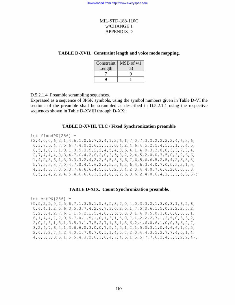
MIL-STD-188-110C
w/CHANGE 1
APPENDIX D
167
TABLE D-XVII. Constraint length and voice mode mapping.
Constraint
Length
MSB of w1
d3
7 0
9 1
D.5.2.1.4 Preamble scrambling sequences.
Expressed as a sequence of 8PSK symbols, using the symbol numbers given in Table D-VI the
sections of the preamble shall be scrambled as described in D.5.2.1.1 using the respective
sequences shown in Table D-XVIII through D-XX:
TABLE D-XVIII. TLC / Fixed Synchronization preamble
int fixedPN[256] =
{2,4,0,0,6,2,1,4,6,1,0,5,7,3,4,1,2,6,1,7,0,7,3,2,2,2,3,2,4,6,3,6,
6,3,7,5,4,7,5,6,7,4,0,2,6,1,5,3,0,4,2,4,6,4,5,2,5,4,5,3,1,5,4,5,
6,5,1,0,7,1,0,1,0,5,3,5,2,2,4,5,4,0,6,4,1,4,0,3,3,0,0,3,3,7,3,4,
2,7,4,4,4,0,3,4,7,6,4,2,6,2,0,3,5,3,2,2,4,5,2,0,0,3,5,0,3,2,6,6,
1,4,2,3,6,1,3,0,3,3,2,4,2,2,6,5,5,3,6,7,6,5,6,6,5,2,5,4,2,3,3,3,
5,7,5,5,3,7,0,4,7,0,4,1,6,2,3,5,5,6,2,6,4,6,3,4,0,7,0,0,5,2,1,5,
4,3,4,5,7,0,5,3,7,6,6,6,4,5,6,0,2,0,4,2,3,4,4,0,7,6,6,2,0,0,3,3,
0,5,2,4,2,2,4,5,4,6,6,6,3,2,1,0,3,2,6,0,6,2,4,0,6,4,1,3,3,5,3,6};
TABLE D-XIX. Count Synchronization preamble.
int cntPN[256] =
{5,5,2,2,0,2,5,6,7,1,3,5,1,5,6,5,3,7,0,4,0,3,3,2,1,3,0,3,1,6,2,6,
0,6,4,1,2,5,6,3,5,3,7,4,2,6,7,3,0,2,0,1,7,5,0,6,1,5,0,3,2,2,5,2,
5,2,3,4,2,7,6,1,1,5,2,1,5,4,0,3,5,5,0,3,1,4,0,5,0,3,0,6,0,0,3,1,
6,1,4,4,7,7,0,5,7,0,1,5,1,0,1,3,1,5,0,7,1,2,2,2,7,1,2,5,0,3,3,2,
2,0,4,5,1,3,1,3,5,3,1,7,5,2,7,1,3,1,5,6,2,4,6,0,6,1,0,0,3,6,2,7,
3,2,4,7,6,4,1,3,6,6,0,3,0,0,7,5,4,5,1,2,1,5,0,3,1,0,4,6,6,1,0,5,
2,6,3,2,7,4,2,4,0,1,7,0,7,0,5,1,4,5,7,2,0,4,4,3,5,2,7,7,4,5,1,4,
4,6,3,3,0,5,1,5,5,4,3,2,0,3,0,4,7,4,5,1,5,5,7,7,6,2,4,3,5,2,2,4};
Downloaded from http://www.everyspec.com

MIL-STD-188-110C
w/CHANGE 1
APPENDIX D
168
TABLE D-XX. Waveform Number Synchronization preamble.
int widPN[256] =
{2,3,0,3,7,3,3,0,1,4,4,6,5,5,4,5,6,2,0,5,6,6,5,3,5,5,2,2,1,2,3,6,
1,1,4,3,1,0,5,1,0,3,3,0,3,0,4,4,6,2,5,6,1,7,2,6,2,0,0,4,7,2,3,5,
2,7,1,6,5,0,4,1,6,2,1,5,4,3,5,0,3,4,1,3,2,1,6,1,5,7,0,4,7,6,6,0,
4,7,6,6,6,6,2,3,5,0,7,0,3,1,5,1,2,0,5,3,2,4,5,6,6,7,7,3,5,1,6,0,
1,4,4,5,6,0,6,7,2,4,4,0,3,7,2,0,0,1,4,0,7,1,7,4,5,4,5,5,5,3,3,2,
0,5,1,3,1,5,3,4,1,5,4,1,4,4,2,2,4,3,0,7,4,1,5,7,1,4,7,2,5,5,6,6,
1,6,5,6,3,0,2,5,7,7,4,4,3,4,4,6,0,7,2,2,0,0,2,1,0,0,3,6,6,4,0,2,
4,3,4,5,2,6,3,7,7,5,7,3,0,7,0,0,7,2,6,2,2,6,1,4,3,7,6,5,0,6,5,4};
D.5.2.2 Mini-probes.
Mini-probes shall be inserted, following every data block and at the end of each preamble, for
non-Walsh based modulations (i.e., all except Waveform ID 0). To support the wide range of
bit rate and bandwidth options of this standard, 14 different mini-probe sequences are utilized.
Each of the mini-probes consists of the base sequence cyclically extended to the required
length.
The mini-probes are also utilized to identify the long interleaver block boundary. This is
accomplished by transmitting a cyclically rotated version of the mini-probe following the
second to last data block of the long interleaver frame. The position of this cyclically shifted
mini-probe remains constant regardless of which interleaver has actually been selected. As all
interleavers line up on the long interleaver block boundary, this feature can be used to
synchronize to a broadcast transmission and provide a late entry feature when the Waveform ID
fields are known in advance by the receiver. The cyclically rotated version of the mini-probe is
obtained by first cyclically extending the base sequence, and then shifting by a predetermined
number of symbols.
Table D-XXI defines the mini-probe lengths and the base sequence used to generate the full
mini-probe and also the cyclic shift utilized to signal the interleaver block boundary.
Downloaded from http://www.everyspec.com
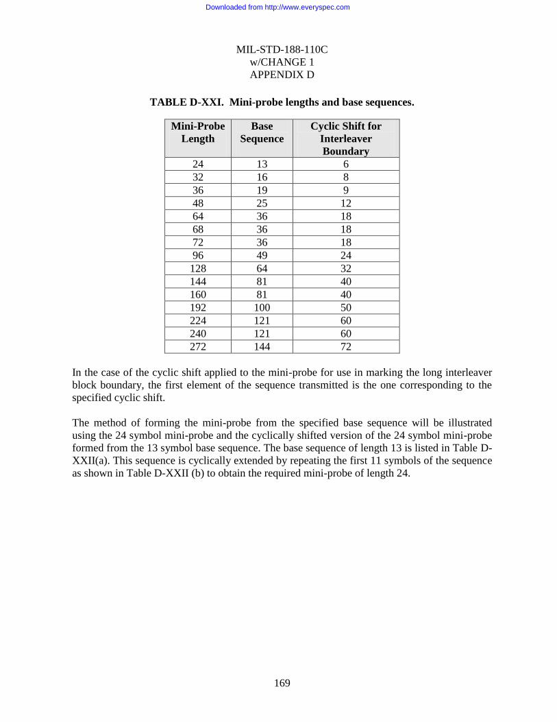
MIL-STD-188-110C
w/CHANGE 1
APPENDIX D
169
TABLE D-XXI. Mini-probe lengths and base sequences.
Mini-Probe
Length
Base
Sequence
Cyclic Shift for
Interleaver
Boundary
24 13 6
32 16 8
36 19 9
48 25 12
64 36 18
68 36 18
72 36 18
96 49 24
128 64 32
144 81 40
160 81 40
192 100 50
224 121 60
240 121 60
272 144 72
In the case of the cyclic shift applied to the mini-probe for use in marking the long interleaver
block boundary, the first element of the sequence transmitted is the one corresponding to the
specified cyclic shift.
The method of forming the mini-probe from the specified base sequence will be illustrated
using the 24 symbol mini-probe and the cyclically shifted version of the 24 symbol mini-probe
formed from the 13 symbol base sequence. The base sequence of length 13 is listed in Table D-
XXII(a). This sequence is cyclically extended by repeating the first 11 symbols of the sequence
as shown in Table D-XXII (b) to obtain the required mini-probe of length 24.
Downloaded from http://www.everyspec.com
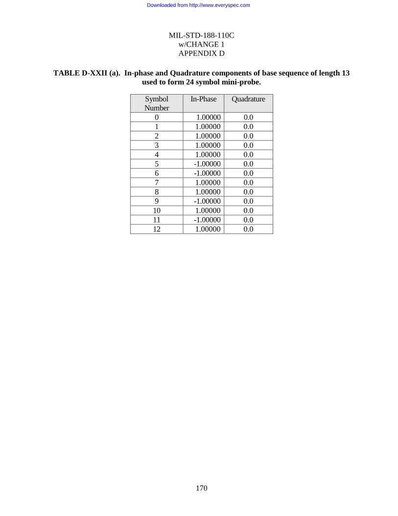
MIL-STD-188-110C
w/CHANGE 1
APPENDIX D
170
TABLE D-XXII (a). In-phase and Quadrature components of base sequence of length 13
used to form 24 symbol mini-probe.
Symbol
Number
In-Phase Quadrature
0 1.00000 0.0
1 1.00000 0.0
2 1.00000 0.0
3 1.00000 0.0
4 1.00000 0.0
5 -1.00000 0.0
6 -1.00000 0.0
7 1.00000 0.0
8 1.00000 0.0
9 -1.00000 0.0
10 1.00000 0.0
11 -1.00000 0.0
12 1.00000 0.0
Downloaded from http://www.everyspec.com
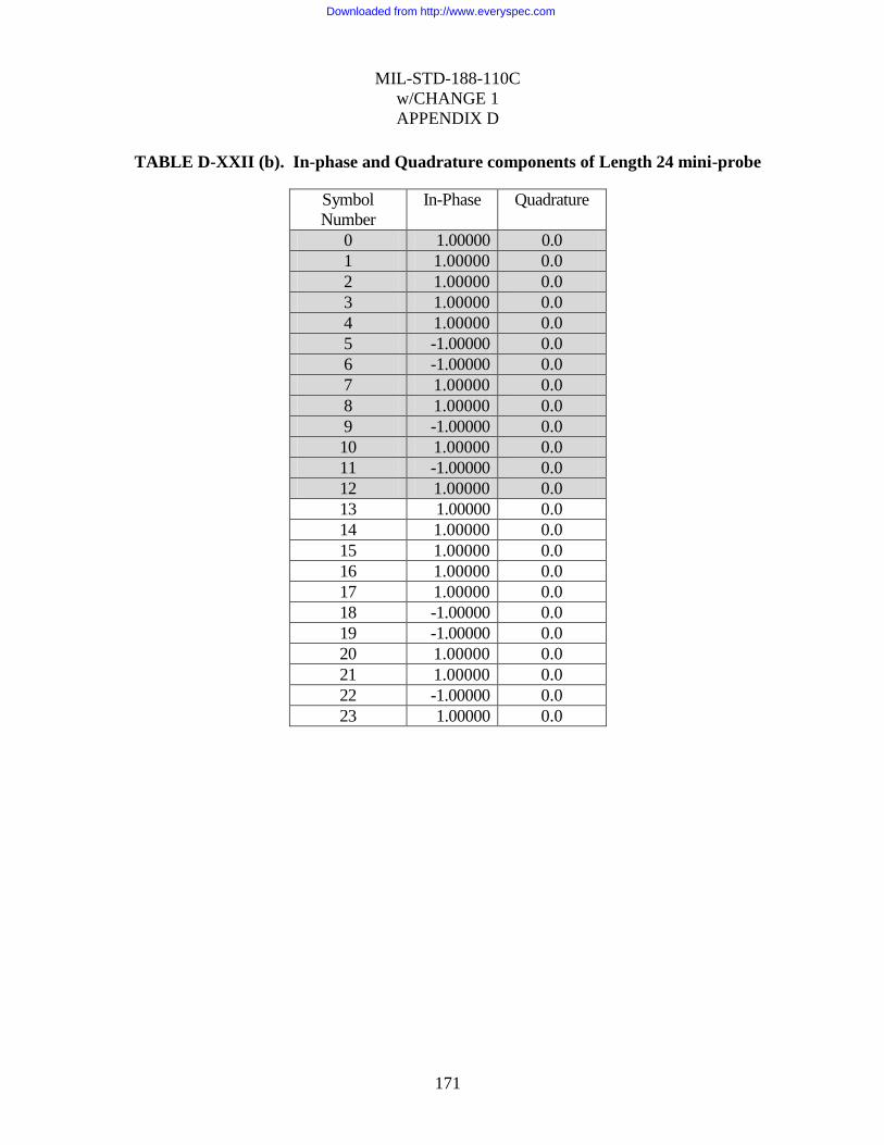
MIL-STD-188-110C
w/CHANGE 1
APPENDIX D
171
TABLE D-XXII (b). In-phase and Quadrature components of Length 24 mini-probe
Symbol
Number
In-Phase Quadrature
0 1.00000 0.0
1 1.00000 0.0
2 1.00000 0.0
3 1.00000 0.0
4 1.00000 0.0
5 -1.00000 0.0
6 -1.00000 0.0
7 1.00000 0.0
8 1.00000 0.0
9 -1.00000 0.0
10 1.00000 0.0
11 -1.00000 0.0
12 1.00000 0.0
13 1.00000 0.0
14 1.00000 0.0
15 1.00000 0.0
16 1.00000 0.0
17 1.00000 0.0
18 -1.00000 0.0
19 -1.00000 0.0
20 1.00000 0.0
21 1.00000 0.0
22 -1.00000 0.0
23 1.00000 0.0
Downloaded from http://www.everyspec.com

MIL-STD-188-110C
w/CHANGE 1
APPENDIX D
172
Table D-XXII(c) provides an example of the cyclic shift of the 24 symbol mini-probe. As
specified in Table D-XXI, the shifted mini-probe sequence begins 6 symbols into the original
13 symbol base sequence. Thus, the shifted mini-probe contains the last 7 symbols of the length
13 base sequence, followed by a complete length 13 base sequence, followed by the first 4
symbols of the length 13 base sequence to complete the 24 symbol mini-probe.
TABLE D-XXII(c). In-phase and Quadrature components of Length 24 mini-probe
cyclically shifted by 6 symbols
Symbol
Number
In-Phase Quadrature
0 -1.00000 0.0
1 1.00000 0.0
2 1.00000 0.0
3 -1.00000 0.0
4 1.00000 0.0
5 -1.00000 0.0
6 1.00000 0.0
7 1.00000 0.0
8 1.00000 0.0
9 1.00000 0.0
10 1.00000 0.0
11 1.00000 0.0
12 -1.00000 0.0
13 -1.00000 0.0
14 1.00000 0.0
15 1.00000 0.0
16 -1.00000 0.0
17 1.00000 0.0
18 -1.00000 0.0
19 1.00000 0.0
20 1.00000 0.0
21 1.00000 0.0
22 1.00000 0.0
23 1.00000 0.0
Downloaded from http://www.everyspec.com
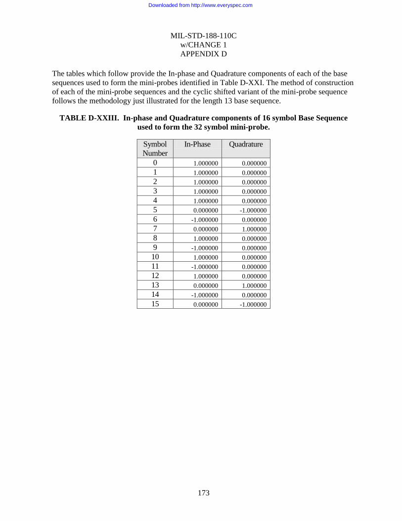
MIL-STD-188-110C
w/CHANGE 1
APPENDIX D
173
The tables which follow provide the In-phase and Quadrature components of each of the base
sequences used to form the mini-probes identified in Table D-XXI. The method of construction
of each of the mini-probe sequences and the cyclic shifted variant of the mini-probe sequence
follows the methodology just illustrated for the length 13 base sequence.
TABLE D-XXIII. In-phase and Quadrature components of 16 symbol Base Sequence
used to form the 32 symbol mini-probe.
Symbol
Number In-Phase Quadrature
0 1.000000 0.000000
1 1.000000 0.000000
2 1.000000 0.000000
3 1.000000 0.000000
4 1.000000 0.000000
5 0.000000 -1.000000
6 -1.000000 0.000000
7 0.000000 1.000000
8 1.000000 0.000000
9 -1.000000 0.000000
10 1.000000 0.000000
11 -1.000000 0.000000
12 1.000000 0.000000
13 0.000000 1.000000
14 -1.000000 0.000000
15 0.000000 -1.000000
Downloaded from http://www.everyspec.com

MIL-STD-188-110C
w/CHANGE 1
APPENDIX D
174
TABLE D-XXIV. In-phase and Quadrature components of 19 symbol Base Sequence
used to form the 36 symbol mini-probe
Symbol
Number In-Phase Quadrature
0 1.000000 0.000000 1 -1.000000 0.000000 2 1.000000 0.000000 3 1.000000 0.000000 4 -1.000000 0.000000 5 -1.000000 0.000000 6 -1.000000 0.000000 7 -1.000000 0.000000 8 1.000000 0.000000 9 -1.000000 0.000000 10 1.000000 0.000000 11 -1.000000 0.000000 12 1.000000 0.000000 13 1.000000 0.000000 14 1.000000 0.000000 15 1.000000 0.000000 16 -1.000000 0.000000 17 -1.000000 0.000000 18 1.000000 0.000000
Downloaded from http://www.everyspec.com
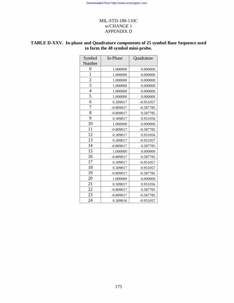
MIL-STD-188-110C
w/CHANGE 1
APPENDIX D
175
TABLE D-XXV. In-phase and Quadrature components of 25 symbol Base Sequence used
to form the 48 symbol mini-probe.
Symbol
Number In-Phase Quadrature
0 1.000000 0.000000
1 1.000000 0.000000
2 1.000000 0.000000
3 1.000000 0.000000
4 1.000000 0.000000
5 1.000000 0.000000
6 0.309017 -0.951057
7 -0.809017 -0.587785
8 -0.809017 0.587785
9 0.309017 0.951056
10 1.000000 0.000000
11 -0.809017 -0.587785
12 0.309017 0.951056
13 0.309017 -0.951057
14 -0.809017 0.587785
15 1.000000 0.000000
16 -0.809017 0.587785
17 0.309017 -0.951057
18 0.309017 0.951057
19 -0.809017 -0.587785
20 1.000000 0.000000
21 0.309017 0.951056
22 -0.809017 0.587785
23 -0.809017 -0.587785
24 0.309016 -0.951057
Downloaded from http://www.everyspec.com

MIL-STD-188-110C
w/CHANGE 1
APPENDIX D
176
TABLE D-XXVI. In-phase and Quadrature components of 36 symbol Base Sequence
used to form the 64 and 72 symbol mini-probes.
Symbol
Number
In-Phase Quadrature
0 1.000000 0.000000
1 1.000000 0.000000
2 1.000000 0.000000
3 1.000000 0.000000
4 1.000000 0.000000
5 1.000000 0.000000
6 1.000000 0.000000
7 0.500000 -0.866025
8 -0.500000 -0.866025
9 -1.000000 0.000000
10 -0.500000 0.866025
11 0.500000 0.866025
12 1.000000 0.000000
13 -0.500000 -0.866025
14 -0.500000 0.866025
15 1.000000 0.000000
16 -0.500000 -0.866025
17 -0.500000 0.866025
18 1.000000 0.000000
19 -1.000000 0.000000
20 1.000000 0.000000
21 -1.000000 0.000000
22 1.000000 0.000000
23 -1.000000 0.000000
24 1.000000 0.000000
25 -0.500000 0.866025
26 -0.500000 -0.866025
27 1.000000 0.000000
28 -0.500000 0.866026
29 -0.500000 -0.866026
30 1.000000 0.000000
31 0.500000 0.866025
32 -0.500000 0.866025
33 -1.000000 0.000000
34 -0.500000 -0.866026
35 0.500000 -0.866026
Downloaded from http://www.everyspec.com
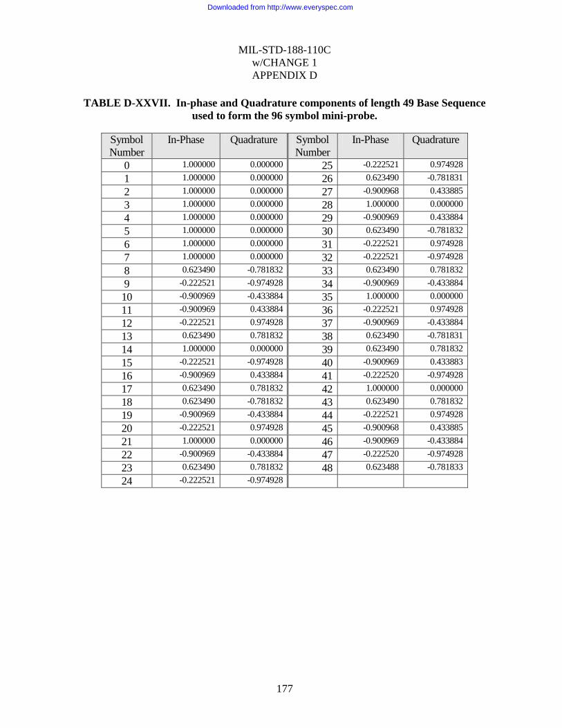
MIL-STD-188-110C
w/CHANGE 1
APPENDIX D
177
TABLE D-XXVII. In-phase and Quadrature components of length 49 Base Sequence
used to form the 96 symbol mini-probe.
Symbol
Number
In-Phase Quadrature Symbol
Number
In-Phase Quadrature
0 1.000000 0.000000 25 -0.222521 0.974928
1 1.000000 0.000000 26 0.623490 -0.781831
2 1.000000 0.000000 27 -0.900968 0.433885
3 1.000000 0.000000 28 1.000000 0.000000
4 1.000000 0.000000 29 -0.900969 0.433884
5 1.000000 0.000000 30 0.623490 -0.781832
6 1.000000 0.000000 31 -0.222521 0.974928
7 1.000000 0.000000 32 -0.222521 -0.974928
8 0.623490 -0.781832 33 0.623490 0.781832
9 -0.222521 -0.974928 34 -0.900969 -0.433884
10 -0.900969 -0.433884 35 1.000000 0.000000
11 -0.900969 0.433884 36 -0.222521 0.974928
12 -0.222521 0.974928 37 -0.900969 -0.433884
13 0.623490 0.781832 38 0.623490 -0.781831
14 1.000000 0.000000 39 0.623490 0.781832
15 -0.222521 -0.974928 40 -0.900969 0.433883
16 -0.900969 0.433884 41 -0.222520 -0.974928
17 0.623490 0.781832 42 1.000000 0.000000
18 0.623490 -0.781832 43 0.623490 0.781832
19 -0.900969 -0.433884 44 -0.222521 0.974928
20 -0.222521 0.974928 45 -0.900968 0.433885
21 1.000000 0.000000 46 -0.900969 -0.433884
22 -0.900969 -0.433884 47 -0.222520 -0.974928
23 0.623490 0.781832 48 0.623488 -0.781833
24 -0.222521 -0.974928
Downloaded from http://www.everyspec.com

MIL-STD-188-110C
w/CHANGE 1
APPENDIX D
178
TABLE D-XXVIII. In-phase and Quadrature components of length 64 Base Sequence
used to form128 symbol mini-probe.
Symbol
Number
In-Phase Quadrature Symbol
Number
In-Phase Quadrature
0 1.000000 0.000000 32 1.000000 0.000000
1 1.000000 0.000000 33 -1.000000 0.000000
2 1.000000 0.000000 34 1.000000 0.000000
3 1.000000 0.000000 35 -1.000000 0.000000
4 1.000000 0.000000 36 1.000000 0.000000
5 1.000000 0.000000 37 -1.000000 0.000000
6 1.000000 0.000000 38 1.000000 0.000000
7 1.000000 0.000000 39 -1.000000 -0.000000
8 1.000000 0.000000 40 1.000000 0.000000
9 0.707107 -0.707107 41 -0.707107 0.707107
10 0.000000 -1.000000 42 0.000000 -1.000000
11 -0.707107 -0.707107 43 0.707107 0.707107
12 -1.000000 0.000000 44 -1.000000 0.000000
13 -0.707107 0.707107 45 0.707107 -0.707107
14 0.000000 1.000000 46 0.000000 1.000000
15 0.707107 0.707107 47 -0.707107 -0.707107
16 1.000000 0.000000 48 1.000000 0.000000
17 0.000000 -1.000000 49 0.000000 1.000000
18 -1.000000 0.000000 50 -1.000000 0.000000
19 0.000000 1.000000 51 0.000000 -1.000000
20 1.000000 0.000000 52 1.000000 0.000000
21 0.000000 -1.000000 53 0.000000 1.000000
22 -1.000000 0.000000 54 -1.000000 0.000000
23 0.000000 1.000000 55 0.000000 -1.000000
24 1.000000 0.000000 56 1.000000 0.000000
25 -0.707107 -0.707107 57 0.707107 0.707107
26 0.000000 1.000000 58 0.000000 1.000000
27 0.707107 -0.707107 59 -0.707107 0.707106
28 -1.000000 0.000000 60 -1.000000 -0.000001
29 0.707107 0.707107 61 -0.707107 -0.707107
30 0.000000 -1.000000 62 0.000000 -1.000000
31 -0.707107 0.707106 63 0.707108 -0.707106
Downloaded from http://www.everyspec.com

MIL-STD-188-110C
w/CHANGE 1
APPENDIX D
179
TABLE D-XXIX. In-phase and Quadrature components of 81 symbol Base Sequence
used to form the 144 and 160 symbol mini-probes.
Symbol
Number
In-Phase Quadrature Symbol
Number
In-Phase Quadrature
0 1.000000 0.000000 32 -0.500000 0.866025
1 1.000000 0.000000 33 1.000000 0.000000
2 1.000000 0.000000 34 -0.500000 -0.866025
3 1.000000 0.000000 35 -0.500000 0.866026
4 1.000000 0.000000 36 1.000000 0.000000
5 1.000000 0.000000 37 -0.939693 -0.342020
6 1.000000 0.000000 38 0.766044 0.642788
7 1.000000 0.000000 39 -0.500000 -0.866025
8 1.000000 0.000000 40 0.173648 0.984808
9 1.000000 0.000000 41 0.173648 -0.984808
10 0.766044 -0.642788 42 -0.500000 0.866026
11 0.173648 -0.984808 43 0.766044 -0.642788
12 -0.500000 -0.866025 44 -0.939693 0.342020
13 -0.939693 -0.342020 45 1.000000 0.000000
14 -0.939693 0.342020 46 -0.939693 0.342020
15 -0.500000 0.866025 47 0.766044 -0.642788
16 0.173648 0.984808 48 -0.500000 0.866025
17 0.766044 0.642788 49 0.173648 -0.984808
18 1.000000 0.000000 50 0.173649 0.984808
19 0.173648 -0.984808 51 -0.500000 -0.866026
20 -0.939693 -0.342020 52 0.766045 0.642787
21 -0.500000 0.866025 53 -0.939693 -0.342020
22 0.766044 0.642788 54 1.000000 0.000000
23 0.766044 -0.642788 55 -0.500000 0.866025
24 -0.500000 -0.866025 56 -0.500000 -0.866025
25 -0.939693 0.342020 57 1.000000 0.000000
26 0.173648 0.984808 58 -0.500000 0.866026
27 1.000000 0.000000 59 -0.500000 -0.866026
28 -0.500000 -0.866025 60 1.000000 -0.000000
29 -0.500000 0.866025 61 -0.500000 0.866025
30 1.000000 0.000000 62 -0.500000 -0.866025
31 -0.500000 -0.866025 63 1.000000 0.000000
Downloaded from http://www.everyspec.com

MIL-STD-188-110C
w/CHANGE 1
APPENDIX D
180
TABLE D-XXIX. In-phase and Quadrature components of 81 symbol Base Sequence
used to form the 144 and 160 symbol mini-probes-Continued
Symbol
Number
In-Phase Quadrature Symbol
Number
In-Phase Quadrature
64 0.173648 0.984808 73 0.766044 0.642788
65 -0.939693 0.342020 74 0.173648 0.984808
66 -0.500000 -0.866025 75 -0.500000 0.866026
67 0.766044 -0.642788 76 -0.939693 0.342020
68 0.766045 0.642787 77 -0.939693 -0.342020
69 -0.500000 0.866025 78 -0.500001 -0.866025
70 -0.939693 -0.342019 79 0.173648 -0.984808
71 0.173648 -0.984808 80 0.766045 -0.642787
72 1.000000 0.000000
Downloaded from http://www.everyspec.com

MIL-STD-188-110C
w/CHANGE 1
APPENDIX D
181
TABLE D-XXX. In-phase and Quadrature components of 100 symbol Base Sequence
used to form the 192 symbol mini-probe.
Symbol
Number
In-Phase Quadrature Symbol
Number
In-Phase Quadrature
0 1.000000 0.000000 32 -0.809017 0.587785
1 1.000000 0.000000 33 0.809017 0.587785
2 1.000000 0.000000 34 0.309017 -0.951057
3 1.000000 0.000000 35 -1.000000 0.000000
4 1.000000 0.000000 36 0.309017 0.951057
5 1.000000 0.000000 37 0.809017 -0.587785
6 1.000000 0.000000 38 -0.809017 -0.587785
7 1.000000 0.000000 39 -0.309018 0.951056
8 1.000000 0.000000 40 1.000000 0.000000
9 1.000000 0.000000 41 -0.809017 -0.587785
10 1.000000 0.000000 42 0.309017 0.951056
11 0.809017 -0.587785 43 0.309017 -0.951057
12 0.309017 -0.951057 44 -0.809017 0.587785
13 -0.309017 -0.951056 45 1.000000 0.000000
14 -0.809017 -0.587785 46 -0.809017 -0.587785
15 -1.000000 0.000000 47 0.309017 0.951057
16 -0.809017 0.587785 48 0.309016 -0.951057
17 -0.309017 0.951056 49 -0.809017 0.587785
18 0.309017 0.951056 50 1.000000 0.000000
19 0.809017 0.587785 51 -1.000000 0.000000
20 1.000000 0.000000 52 1.000000 0.000000
21 0.309017 -0.951057 53 -1.000000 0.000000
22 -0.809017 -0.587785 54 1.000000 0.000000
23 -0.809017 0.587785 55 -1.000000 0.000000
24 0.309017 0.951056 56 1.000000 0.000000
25 1.000000 0.000000 57 -1.000000 -0.000000
26 0.309017 -0.951057 58 1.000000 -0.000000
27 -0.809017 -0.587785 59 -1.000000 0.000000
28 -0.809017 0.587785 60 1.000000 0.000000
29 0.309017 0.951057 61 -0.809017 0.587785
30 1.000000 0.000000 62 0.309017 -0.951057
31 -0.309017 -0.951056 63 0.309017 0.951057
Downloaded from http://www.everyspec.com
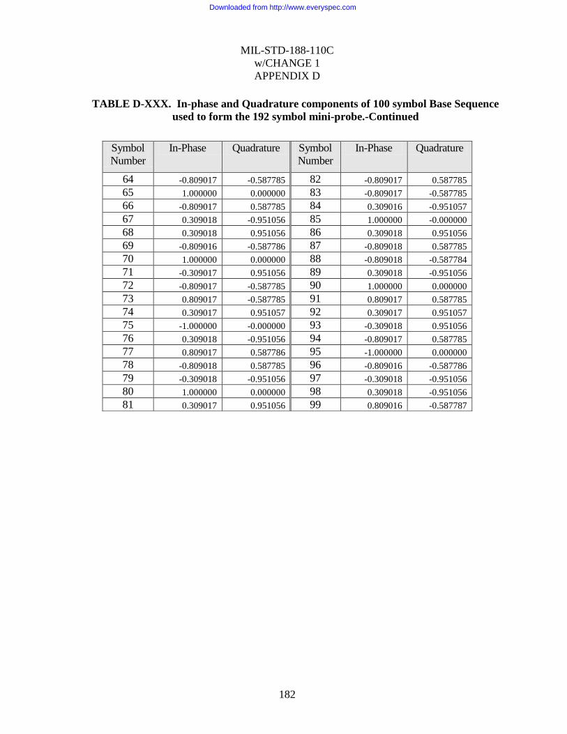
MIL-STD-188-110C
w/CHANGE 1
APPENDIX D
182
TABLE D-XXX. In-phase and Quadrature components of 100 symbol Base Sequence
used to form the 192 symbol mini-probe.-Continued
Symbol
Number
In-Phase Quadrature Symbol
Number
In-Phase Quadrature
64 -0.809017 -0.587785 82 -0.809017 0.587785
65 1.000000 0.000000 83 -0.809017 -0.587785
66 -0.809017 0.587785 84 0.309016 -0.951057
67 0.309018 -0.951056 85 1.000000 -0.000000
68 0.309018 0.951056 86 0.309018 0.951056
69 -0.809016 -0.587786 87 -0.809018 0.587785
70 1.000000 0.000000 88 -0.809018 -0.587784
71 -0.309017 0.951056 89 0.309018 -0.951056
72 -0.809017 -0.587785 90 1.000000 0.000000
73 0.809017 -0.587785 91 0.809017 0.587785
74 0.309017 0.951057 92 0.309017 0.951057
75 -1.000000 -0.000000 93 -0.309018 0.951056
76 0.309018 -0.951056 94 -0.809017 0.587785
77 0.809017 0.587786 95 -1.000000 0.000000
78 -0.809018 0.587785 96 -0.809016 -0.587786
79 -0.309018 -0.951056 97 -0.309018 -0.951056
80 1.000000 0.000000 98 0.309018 -0.951056
81 0.309017 0.951056 99 0.809016 -0.587787
Downloaded from http://www.everyspec.com

MIL-STD-188-110C
w/CHANGE 1
APPENDIX D
183
TABLE D-XXXI. In-phase and Quadrature components of 121 symbol Base Sequence
used to form the 224 and 240 symbol mini-probes.
Symbol
Number
In-Phase Quadrature Symbol
Number
In-Phase Quadrature
0 1.000000 0.000000 32 0.415415 0.909632
1 1.000000 0.000000 33 1.000000 0.000000
2 1.000000 0.000000 34 -0.142315 -0.989821
3 1.000000 0.000000 35 -0.959493 0.281733
4 1.000000 0.000000 36 0.415415 0.909632
5 1.000000 0.000000 37 0.841254 -0.540641
6 1.000000 0.000000 38 -0.654861 -0.755750
7 1.000000 0.000000 39 -0.654861 0.755750
8 1.000000 0.000000 40 0.841253 0.540641
9 1.000000 0.000000 41 0.415415 -0.909632
10 1.000000 0.000000 42 -0.959493 -0.281732
11 1.000000 0.000000 43 -0.142315 0.989821
12 0.841254 -0.540641 44 1.000000 0.000000
13 0.415415 -0.909632 45 -0.654861 -0.755750
14 -0.142315 -0.989821 46 -0.142315 0.989821
15 -0.654861 -0.755750 47 0.841254 -0.540641
16 -0.959493 -0.281733 48 -0.959493 -0.281733
17 -0.959493 0.281733 49 0.415415 0.909632
18 -0.654861 0.755750 50 0.415415 -0.909632
19 -0.142315 0.989821 51 -0.959493 0.281733
20 0.415415 0.909632 52 0.841253 0.540641
21 0.841253 0.540641 53 -0.142315 -0.989821
22 1.000000 0.000000 54 -0.654861 0.755749
23 0.415415 -0.909632 55 1.000000 0.000000
24 -0.654861 -0.755750 56 -0.959493 -0.281733
25 -0.959493 0.281733 57 0.841253 0.540641
26 -0.142315 0.989821 58 -0.654861 -0.755750
27 0.841253 0.540641 59 0.415415 0.909632
28 0.841254 -0.540641 60 -0.142315 -0.989821
29 -0.142315 -0.989821 61 -0.142315 0.989821
30 -0.959493 -0.281733 62 0.415415 -0.909632
31 -0.654861 0.755750 63 -0.654861 0.755749
Downloaded from http://www.everyspec.com

MIL-STD-188-110C
w/CHANGE 1
APPENDIX D
184
TABLE D-XXXI. In-phase and Quadrature components of 121 symbol Base Sequence
used to form the 224 and 240 symbol mini-probes.-Continued
Symbol
Number
In-Phase Quadrature Symbol
Number
In-Phase Quadrature
64 0.841254 -0.540640 93 -0.654861 0.755749
65 -0.959493 0.281732 94 -0.654861 -0.755750
66 1.000000 0.000000 95 0.841253 -0.540641
67 -0.959493 0.281733 96 0.415414 0.909633
68 0.841254 -0.540641 97 -0.959493 0.281733
69 -0.654861 0.755750 98 -0.142314 -0.989822
70 0.415415 -0.909632 99 1.000000 0.000000
71 -0.142315 0.989821 100 0.415415 0.909632
72 -0.142315 -0.989821 101 -0.654861 0.755750
73 0.415414 0.909632 102 -0.959493 -0.281732
74 -0.654861 -0.755750 103 -0.142315 -0.989821
75 0.841254 0.540640 104 0.841254 -0.540640
76 -0.959493 -0.281733 105 0.841254 0.540640
77 1.000000 0.000000 106 -0.142315 0.989821
78 -0.654861 0.755750 107 -0.959493 0.281733
79 -0.142315 -0.989821 108 -0.654862 -0.755748
80 0.841253 0.540641 109 0.415416 -0.909632
81 -0.959493 0.281733 110 1.000000 0.000000
82 0.415415 -0.909632 111 0.841253 0.540641
83 0.415414 0.909632 112 0.415415 0.909632
84 -0.959493 -0.281732 113 -0.142315 0.989821
85 0.841253 -0.540641 114 -0.654861 0.755749
86 -0.142315 0.989821 115 -0.959493 0.281732
87 -0.654860 -0.755750 116 -0.959493 -0.281733
88 1.000000 0.000000 117 -0.654860 -0.755750
89 -0.142315 0.989821 118 -0.142314 -0.989822
90 -0.959493 -0.281733 119 0.415416 -0.909632
91 0.415415 -0.909632 120 0.841254 -0.540640
92 0.841253 0.540641
Downloaded from http://www.everyspec.com

MIL-STD-188-110C
w/CHANGE 1
APPENDIX D
185
TABLE D-XXXII. In-phase and Quadrature components of 144 symbol Base Sequence
used to form the 272 symbol mini-probe.
Symbol
Number
In-Phase Quadrature Symbol
Number
In-Phase Quadrature
0 1.000000 0.000000 32 -0.500000 -0.866025
1 1.000000 0.000000 33 -1.000000 0.000000
2 1.000000 0.000000 34 -0.500000 0.866025
3 1.000000 0.000000 35 0.500000 0.866026
4 1.000000 0.000000 36 1.000000 0.000000
5 1.000000 0.000000 37 0.000000 -1.000000
6 1.000000 0.000000 38 -1.000000 0.000000
7 1.000000 0.000000 39 0.000000 1.000000
8 1.000000 0.000000 40 1.000000 0.000000
9 1.000000 0.000000 41 0.000000 -1.000000
10 1.000000 0.000000 42 -1.000000 0.000000
11 1.000000 0.000000 43 0.000000 1.000000
12 1.000000 0.000000 44 1.000000 0.000000
13 0.866025 -0.500000 45 0.000000 -1.000000
14 0.500000 -0.866025 46 -1.000000 0.000000
15 0.000000 -1.000000 47 -0.000001 1.000000
16 -0.500000 -0.866025 48 1.000000 0.000000
17 -0.866025 -0.500000 49 -0.500000 -0.866025
18 -1.000000 0.000000 50 -0.500000 0.866025
19 -0.866025 0.500000 51 1.000000 0.000000
20 -0.500000 0.866025 52 -0.500000 -0.866025
21 0.000000 1.000000 53 -0.500000 0.866025
22 0.500000 0.866025 54 1.000000 0.000000
23 0.866025 0.500000 55 -0.500000 -0.866025
24 1.000000 0.000000 56 -0.500000 0.866026
25 0.500000 -0.866025 57 1.000000 0.000000
26 -0.500000 -0.866025 58 -0.500000 -0.866026
27 -1.000000 0.000000 59 -0.500001 0.866025
28 -0.500000 0.866025 60 1.000000 0.000000
29 0.500000 0.866025 61 -0.866025 -0.500000
30 1.000000 0.000000 62 0.500000 0.866025
31 0.500000 -0.866025 63 0.000000 -1.000000
Downloaded from http://www.everyspec.com

MIL-STD-188-110C
w/CHANGE 1
APPENDIX D
186
TABLE D-XXXII. In-phase and Quadrature components of 144 symbol Base Sequence
used to form the 272 symbol mini-probe.-Continued
Symbol
Number
In-Phase Quadrature Symbol
Number
In-Phase Quadrature
64 -0.500000 0.866025 96 1.000000 0.000000
65 0.866025 -0.500000 97 -0.500000 0.866025
66 -1.000000 0.000000 98 -0.500000 -0.866025
67 0.866025 0.500001 99 1.000000 0.000000
68 -0.500000 -0.866026 100 -0.500000 0.866026
69 0.000000 1.000000 101 -0.500000 -0.866026
70 0.500000 -0.866026 102 1.000000 -0.000001
71 -0.866025 0.500001 103 -0.500000 0.866025
72 1.000000 0.000000 104 -0.500001 -0.866025
73 -1.000000 0.000000 105 1.000000 0.000000
74 1.000000 0.000000 106 -0.500001 0.866025
75 -1.000000 0.000000 107 -0.499999 -0.866026
76 1.000000 0.000000 108 1.000000 0.000000
77 -1.000000 0.000000 109 0.000000 1.000000
78 1.000000 0.000000 110 -1.000000 0.000000
79 -1.000000 -0.000001 111 0.000000 -1.000000
80 1.000000 -0.000001 112 1.000000 0.000000
81 -1.000000 0.000000 113 0.000000 1.000000
82 1.000000 0.000001 114 -1.000000 0.000000
83 -1.000000 -0.000001 115 0.000002 -1.000000
84 1.000000 0.000000 116 1.000000 0.000000
85 -0.866025 0.500000 117 -0.000002 1.000000
86 0.500000 -0.866025 118 -1.000000 0.000000
87 0.000000 1.000000 119 0.000002 -1.000000
88 -0.500000 -0.866025 120 1.000000 0.000000
89 0.866025 0.500001 121 0.500000 0.866025
90 -1.000000 -0.000001 122 -0.500000 0.866025
91 0.866026 -0.500000 123 -1.000000 0.000000
92 -0.500000 0.866025 124 -0.500000 -0.866026
93 0.000002 -1.000000 125 0.500000 -0.866026
94 0.499999 0.866026 126 1.000000 0.000001
95 -0.866025 -0.500001 127 0.499999 0.866026
Downloaded from http://www.everyspec.com

MIL-STD-188-110C
w/CHANGE 1
APPENDIX D
187
TABLE D-XXXII. In-phase and Quadrature components of 144 symbol Base Sequence
used to form the 272 symbol mini-probe.-Continued
D.5.3 Coding and interleaving.
The interleaver used shall be a block interleaver. Each block of input data shall also be
encoded using a block encoding technique with a code block size equal to the size of the block
interleaver. Thus, the input data bits will be sent as successive blocks of bits that span the
duration of the interleaver length selected. Tables D-XXXIII through D-XL show the number
of input data bits per block as function of both data rate and interleaver length, one table for
each bandwidth. Note that the “Number of Input Bits” should not be confused with the
“Number of Bits,” which is the interleaver size. The bits from an input data block will be
mapped through the coding and interleaving into a number of data frames and it is the number
of bits per frame times the number of data frames that defines the interleaver length.
Symbol
Number
In-Phase Quadrature Symbol
Number
In-Phase Quadrature
128 -0.500001 0.866025 136 -0.500000 0.866025
129 -1.000000 0.000000 137 -0.866025 0.500000
130 -0.500001 -0.866025 138 -1.000000 -0.000000
131 0.499998 -0.866026 139 -0.866025 -0.500000
132 1.000000 0.000000 140 -0.499999 -0.866026
133 0.866025 0.500000 141 0.000000 -1.000000
134 0.500000 0.866026 142 0.500000 -0.866026
135 -0.000001 1.000000 143 0.866025 -0.500000
Downloaded from http://www.everyspec.com

MIL-STD-188-110C
w/CHANGE 1
APPENDIX D
188
TABLE D-XXXIII. Interleaver Parameters for 3kHz Bandwidth
Waveform
Number
UltraShort Short Medium Long
Number
of
Frames
Number
of
bits
Number
of Input
Bits
Number
of
Frames
Number
of
bits
Number
of Input
Bits
Number
of
Frames
Number
of
bits
Number
of Input
Bits
Number
of
Frames
Number
of
bits
Number
of Input
Bits
0 - - - 40 80 40 144 288 144 576 1152 576
1 4 192 24 16 768 96 64 3072 384 256 12288 1536
2 4 192 48 16 768 192 64 3072 768 256 12288 3072
3 2 192 64 8 768 256 32 3072 1024 128 12288 4096
4 2 192 128 8 768 512 32 3072 2048 128 12288 8192
5 1 256 192 4 1024 768 16 4096 3072 64 16384 12288
6 1 512 384 4 2048 1536 16 8192 6144 64 32768 24576
7 1 768 576 4 3072 2304 16 12288 9216 64 49152 36864
8 1 1024 768 4 4096 3072 16 16384 12288 64 65536 49152
9 1 1280 960 4 5120 3840 16 20480 15360 64 81920 61440
10 1 1536 1152 4 6144 4608 16 24576 18432 64 98304 73728
11 1 2160 1920 4 8640 7680 16 34560 30720 64 138240 122880
12 1 2880 2560 4 11520 10240 16 46080 40960 64 184320 163840
13 1 512 288 4 2048 1152 16 8192 4608 64 32768 18432
Downloaded from http://www.everyspec.com

MIL-STD-188-110C
w/CHANGE 1
APPENDIX D
189
TABLE D-XXXIV. Interleaver Parameters for 6kHz Bandwidth
Waveform
Number
UltraShort Short Medium Long
Number
of
Frames
Number
of
bits
Number
of Input
Bits
Number
of
Frames
Number
of
bits
Number
of Input
Bits
Number
of
Frames
Number
of
bits
Number
of Input
Bits
Number
of
Frames
Number
of
bits
Number
of Input
Bits
0 - - - 80 160 80 288 576 288 1152 2304 1152
1 4 384 48 16 1536 192 64 6144 768 256 24576 3072
2 4 384 96 16 1536 384 64 6144 1536 256 24576 6144
3 2 408 136 8 1632 544 32 6528 2176 128 26112 8704
4 2 408 272 8 1632 1088 32 6528 4352 128 26112 17408
5 1 544 408 4 2176 1632 16 8704 6528 64 34816 26112
6 1 1088 816 4 4352 3264 16 17408 13056 64 69632 52224
7 1 1632 1224 4 6528 4896 16 26112 19584 64 104448 78336
8 1 2176 1632 4 8704 6528 16 34816 26112 64 139264 104448
9 1 2720 2040 4 10880 8160 16 43520 32640 64 174080 130560
10 1 3264 2448 4 13056 9792 16 52224 39168 64 208896 156672
11 1 3240 2880 4 12960 11520 16 51840 46080 64 207360 184320
12 1 4320 3840 4 17280 15360 16 69120 61440 64 276480 245760
Downloaded from http://www.everyspec.com

MIL-STD-188-110C
w/CHANGE 1
APPENDIX D
190
TABLE D-XXXV. Interleaver Parameters for 9kHz Bandwidth
Waveform
Number
UltraShort Short Medium Long
Number
of
Frames
Number
of
bits
Number
of Input
Bits
Number
of
Frames
Number
of
bits
Number
of Input
Bits
Number
of
Frames
Number
of
bits
Number
of Input
Bits
Number
of
Frames
Number
of
bits
Number
of Input
Bits
0 - - - 120 240 160 432 864 576 1728 3456 2304
1 2 576 72 8 2304 288 32 9216 1152 128 36864 4608
2 2 576 144 8 2304 576 32 9216 2304 128 36864 9216
3 2 576 288 8 2304 1152 32 9216 4608 128 36864 18432
4 - - - - - - - - - - - -
5 1 768 576 4 3072 2304 16 12288 9216 64 49152 36864
6 1 1536 1152 4 6144 4608 16 24576 18432 64 98304 73728
7 1 2304 1728 4 9216 6912 16 36864 27648 64 147456 110592
8 1 3072 2304 4 12288 9216 16 49152 36864 64 196608 147456
9 1 3840 2880 4 15360 11520 16 61440 46080 64 245760 184320
10 1 4608 3456 4 18432 13824 16 73728 55296 64 294912 221184
11 1 6480 5760 4 25920 23040 16 103680 92160 64 414720 368640
12 1 8640 7680 4 34560 30720 16 138240 122880 64 552960 491520
Downloaded from http://www.everyspec.com

MIL-STD-188-110C
w/CHANGE 1
APPENDIX D
191
TABLE D-XXXVI. Interleaver Parameters for 12kHz Bandwidth
Waveform
Number
UltraShort Short Medium Long
Number
of
Frames
Number
of
bits
Number
of Input
Bits
Number
of
Frames
Number
of
bits
Number
of Input
Bits
Number
of
Frames
Number
of
bits
Number
of Input
Bits
Number
of
Frames
Number
of
bits
Number
of Input
Bits
0 - - - 160 320 160 576 1152 576 2304 4608 2304
1 3 576 72 12 2304 288 48 9216 1152 192 36864 4608
2 3 576 144 12 2304 576 48 9216 2304 192 36864 9216
3 2 768 256 8 3072 1024 32 12288 4096 128 49152 16384
4 2 768 512 8 3072 2048 32 12288 8192 128 49152 32768
5 1 1024 768 4 4096 3072 16 16384 12288 64 65536 49152
6 1 2048 1536 4 8192 6144 16 32768 24576 64 131072 98304
7 1 3072 2304 4 12288 9216 16 49152 36864 64 196608 147456
8 1 4096 3072 4 16384 12288 16 65536 49152 64 262144 196608
9 1 5120 3840 4 20480 15360 16 81920 61440 64 327680 245760
10 1 6144 4608 4 24576 18432 16 98304 73728 64 393216 294912
11 1 6480 5760 4 25920 23040 16 103680 92160 64 414720 368640
12 1 8640 7680 4 34560 30720 16 138240 122880 64 552960 491520
Downloaded from http://www.everyspec.com

MIL-STD-188-110C
w/CHANGE 1
APPENDIX D
192
TABLE D-XXXVII. Interleaver Parameters for 15kHz Bandwidth
Waveform
Number
UltraShort Short Medium Long
Number
of
Frames
Number
of
bits
Number
of Input
Bits
Number
of
Frames
Number
of
bits
Number
of Input
Bits
Number
of
Frames
Number
of
bits
Number
of Input
Bits
Number
of
Frames
Number
of
bits
Number
of Input
Bits
0 - - - 200 400 160 720 1440 576 2880 5760 2304
1 3 864 72 12 3456 288 48 13824 1152 192 55296 4608
2 3 864 144 12 3456 576 48 13824 2304 192 55296 9216
3 3 864 288 12 3456 1152 48 13824 4608 192 55296 18432
4 3 864 576 12 3456 2304 48 13824 9216 192 55296 36864
5 1 1280 960 4 5120 3840 16 20480 15360 64 81920 61440
6 1 2560 1920 4 10240 7680 16 40960 30720 64 163840 122880
7 1 3840 2880 4 15360 11520 16 61440 46080 64 245760 184320
8 1 5120 3840 4 20480 15360 16 81920 61440 64 327680 245760
9 1 6400 4800 4 25600 19200 16 102400 76800 64 409600 307200
10 1 7680 5760 4 30720 23040 16 122880 92160 64 491520 368640
11 1 6912 6144 4 27648 24576 16 110592 98304 64 442368 393216
12 1 9216 8192 4 36864 32768 16 147456 131072 64 589824 524288
Downloaded from http://www.everyspec.com

MIL-STD-188-110C
w/CHANGE 1
APPENDIX D
193
TABLE D-XXXVIII. Interleaver Parameters for 18kHz Bandwidth
Waveform
Number
UltraShort Short Medium Long
Number
of
Frames
Number
of
bits
Number
of Input
Bits
Number
of
Frames
Number
of
bits
Number
of Input
Bits
Number
of
Frames
Number
of
bits
Number
of Input
Bits
Number
of
Frames
Number
of
bits
Number
of Input
Bits
0 - - - 240 480 320 864 1728 1152 3456 6912 4608
1 3 1344 168 12 5376 672 48 21504 2688 192 86016 10752
2 3 1344 336 12 5376 1344 48 21504 5376 192 86016 21504
3 3 1344 672 12 5376 2688 48 21504 10752 192 86016 43008
4 - - - - - - - - - - - -
5 1 1536 1152 4 6144 4608 16 24576 18432 64 98304 73728
6 1 3072 2304 4 12288 9216 16 49152 36864 64 196608 147456
7 1 4608 3456 4 18432 13824 16 73728 55296 64 294912 221184
8 1 6144 4608 4 24576 18432 16 98304 73728 64 393216 294912
9 1 7680 5760 4 30720 23040 16 122880 92160 64 491520 368640
10 1 9216 6912 4 36864 27648 16 147456 110592 64 589824 442368
11 1 11520 10240 4 46080 40960 16 184320 163840 64 737280 655360
12 1 15360 12800 4 61440 51200 16 245760 204800 64 983040 819200
Downloaded from http://www.everyspec.com

MIL-STD-188-110C
w/CHANGE 1
APPENDIX D
194
TABLE D-XXXIX. Interleaver Parameters for 21kHz Bandwidth
Waveform
Number
UltraShort Short Medium Long
Number
of
Frames
Number
of
bits
Number
of Input
Bits
Number
of
Frames
Number
of
bits
Number
of Input
Bits
Number
of
Frames
Number
of
bits
Number
of Input
Bits
Number
of
Frames
Number
of
bits
Number
of Input
Bits
0 - - - 280 560 160 1008 2016 576 4032 8064 2304
1 4 1280 80 16 5120 320 64 20480 1280 256 81920 5120
2 4 1280 160 16 5120 640 64 20480 2560 256 81920 10240
3 4 1280 320 16 5120 1280 64 20480 5120 256 81920 20480
4 4 1280 640 16 5120 2560 64 20480 10240 256 81920 40960
5 1 1344 896 4 5376 3584 16 21504 14336 64 86016 57344
6 1 2688 1792 4 10752 7168 16 43008 28672 64 172032 114688
7 1 4032 2688 4 16128 10752 16 64512 43008 64 258048 172032
8 1 5376 3584 4 21504 14336 16 86016 57344 64 344064 229376
9 1 6720 4480 4 26880 17920 16 107520 71680 64 430080 286720
10 1 8064 5376 4 32256 21504 16 129024 86016 64 516096 344064
11 1 15360 12288 4 61440 49152 16 245760 196608 64 983040 786432
12 1 20480 18432 4 81920 73728 16 327680 294912 64 1310720 1179648
Downloaded from http://www.everyspec.com

MIL-STD-188-110C
w/CHANGE 1
APPENDIX D
195
TABLE D-XL. Interleaver Parameters for 24kHz Bandwidth
Waveform
Number
UltraShort Short Medium Long
Number
of
Frames
Number
of
bits
Number
of Input
Bits
Number
of
Frames
Number
of
bits
Number
of Input
Bits
Number
of
Frames
Number
of
bits
Number
of Input
Bits
Number
of
Frames
Number
of
bits
Number
of Input
Bits
0 - - - 320 640 320 1152 2304 1152 4608 9216 4608
1 4 1088 136 16 4352 544 64 17408 2176 256 69632 8704
2 4 1088 272 16 4352 1088 64 17408 4352 256 69632 17408
3 2 1632 544 8 6528 2176 32 26112 8704 128 104448 34816
4 2 1632 1088 8 6528 4352 32 26112 17408 128 104448 69632
5 1 2176 1632 4 8704 6528 16 34816 26112 64 139264 104448
6 1 4352 3264 4 17408 13056 16 69632 52224 64 278528 208896
7 1 6528 4896 4 26112 19584 16 104448 78336 64 417792 313344
8 1 8704 6528 4 34816 26112 16 139264 104448 64 557056 417792
9 1 10880 8160 4 43520 32640 16 174080 130560 64 696320 522240
10 1 13056 9792 4 52224 39168 16 208896 156672 64 835584 626688
11 1 11520 10240 4 46080 40960 16 184320 163840 64 737280 655360
12 1 15360 12800 4 61440 51200 16 245760 204800 64 983040 819200
Downloaded from http://www.everyspec.com
MIL-STD-188-110C
w/CHANGE 1
APPENDIX D
196
D.5.3.1 Block boundary alignment.
Each code block shall be interleaved within a single interleaver block of the same size. The
boundaries of these blocks shall be aligned such that the beginning of the first data frame shall
coincide with an interleaver boundary. The first data symbol from the first data frame in each
interleaver set shall have as its MSB the first bit fetched from the interleaver. This is no
different from what would normally be expected, but is a requirement.
D.5.3.2 Block encoding.
The full-tail-biting and puncturing techniques shall be used with either a rate 1/2 k=7
convolutional code or a rate 1/2 k=9 convolutional code to produce a block code that is the
same length as the interleaver. For those data rates where the code is punctured to rate 9/10,
8/9, 5/6, 4/5, 3/4, 2/3, 9/16, 1/2, 2/5, 1/3, 2/7, 1/4, 1/6, 1/8, 1/12 and 1/16 the punctured block
shall still fit exactly within the interleaver. Table D-XLI indicates which code rates and
modulations are used by the different waveform and bandwidths supported by this standard.
Downloaded from http://www.everyspec.com

MIL-STD-188-110C
w/CHANGE 1
APPENDIX D
197
TABLE D-XLI. Code Rate and Modulation.
Waveform
Number 0
Walsh 1
BPSK 2
BPSK 3
BPSK 4
BPSK 5
BPSK 6
QPSK 7
8PSK 8
16QAM 9
32QAM 10
64QAM 11
64QAM 12
256QAM 13
QPSK
Bandwidth (kHz)
3 1/2 1/8 1/4 1/3 2/3 3/4 3/4 3/4 3/4 3/4 3/4 8/9 8/9 9/16
6 1/2 1/8 1/4 1/3 2/3 3/4 3/4 3/4 3/4 3/4 3/4 8/9 8/9 9 2/3 1/8 1/4 1/2 - 3/4 3/4 3/4 3/4 3/4 3/4 8/9 8/9 12 1/2 1/8 1/4 1/3 2/3 3/4 3/4 3/4 3/4 3/4 3/4 8/9 8/9 15 2/5 1/12 1/6 1/3 2/3 3/4 3/4 3/4 3/4 3/4 3/4 8/9 8/9 18 2/3 1/8 1/4 1/2 - 3/4 3/4 3/4 3/4 3/4 3/4 8/9 5/6 21 2/7 1/16 1/8 1/4 1/2 2/3 2/3 2/3 2/3 2/3 2/3 4/5 9/10 24 1/2 1/8 1/4 1/3 2/3 3/4 3/4 3/4 3/4 3/4 3/4 8/9 5/6
Downloaded from http://www.everyspec.com

MIL-STD-188-110C
w/CHANGE 1
APPENDIX D
198
D.5.3.2.1 Constraint length 7, rate 1/2 convolutional code.
A constraint length 7, rate 1/2 convolutional code shall be used prior to puncturing. This shall
be the same code as is used in the single-tone waveform described in section 5.3.2 of this
standard. Figure D-9 is a pictorial representation of the encoder.
Polynomials:
(b0) T1 = x6+x
4 + x
3 + x
1 + 1
(b1) T2 = x6+x
5 + x
4 + x
3 + 1
FIGURE D-9. Constraint length 7, rate 1/2 convolutional encoder.
The two summing nodes in the figure represent modulo 2 additions. For each bit input to the
encoder, two bits are taken from the encoder, with the upper output bit b0, generated by
polynomial T1(x), taken first.
b0
b1
Input
+
+
X6 X
5 X
4 X
3 X
2 X 1
Downloaded from http://www.everyspec.com

MIL-STD-188-110C
w/CHANGE 1
APPENDIX D
199
D.5.3.2.2 Constraint length 9, rate 1/2 convolutional code.
A constraint length 9, rate 1/2 convolutional code shall be used prior to puncturing. Figure D-
10 is a pictorial representation of the encoder.
Polynomials:
(b0) T1 = x8+x
6 + x
5 + x
4 + 1
(b1) T2 = x8+x
7 + x
6 + x
5 + x
3 + x
1+1
FIGURE D-10. Constraint length 9, rate 1/2 convolutional encoder.
The two summing nodes in the figure represent modulo 2 additions. For each bit input to the
encoder, two bits are taken from the encoder, with the upper output bit b0, generated by
polynomial T1(x), taken first.
D.5.3.2.3 Full-tail-biting encoding.
To begin encoding each block of input data, the encoder shall be preloaded by shifting in the
first (k-1) input data bits without taking any output bits. These (k-1) input bits shall be
temporarily saved so that they can be used to “flush” the encoder. The first two coded output
bits shall be taken after the (kth) bit has been shifted in, and shall be defined to be the first two
bits of the resulting block code. After the last input data bit has been encoded, the first (k-1)
“saved” data bits shall be encoded. Note that the encoder shift register should not be changed
before encoding these saved bits; i.e., it should be filled with the last seven input data bits. The
(k-1) “saved” data bits are encoded by shifting them into the encoder one at a time, beginning
with the earliest of the (k-1). The encoding thus continues by taking the two resulting coded
output bits as each of the saved (k-1) bits is shifted in. These encoded bits shall be the final bits
of the resulting (unpunctured) block code. Prior to puncturing, the resulting block code will
have exactly twice as many bits as the input information bits. Puncturing of the rate 1/2 code to
the other required rates shall be done prior to sending bits to the interleaver.
b0
b1
Input
+
+
X6 X
5 X
4 X
3 X
2 X 1 X
8 X
7
Downloaded from http://www.everyspec.com

MIL-STD-188-110C
w/CHANGE 1
APPENDIX D
200
D.5.3.2.4 Puncturing and Repetition.
In order to obtain a higher rate code from a lower rate code, the output of the encoder must be
punctured by not transmitting all of the encoder‟s output bits. Which bits are transmitted are
defined by a puncturing mask. For example, when puncturing a rate ½ code to rate ¾ code one
out of every 3 bits must not be transmitted. In this case puncturing shall be performed by using
a puncturing mask of
110
101
In this notation the first row indicates the bits retained by the T1 branch, the second row
indicates the bits retained by the T2 branch. A 1 indicates that the bit is transmitted and a 0
indicates that the bit is not transmitted. For an encoder generated sequence of
T1(k), T2(k), T1(k+1), T2(k+1), T1(k+2), T2(k+2) . . .
the transmitted sequence shall be
T1(k), T2(k), T1(k+1), P, P, T2(k+2) . . .
Defining T1(0), T2(0) to be the first two bits of the block code generated as defined in
paragraph 0, then the value of k in the above sequences shall be an integral multiple of 3. The
block code shall be punctured in this manner before being input to the interleaver.
In order to obtain a lower code rate from a higher code rate repetition can be used. For example
to generate a rate ¼ code from a rate ½ code the two output bits
T1(k), T2(k), T1(k+1), T2(k+1),
Are repeated to yield four output bits for each input bit, giving
T1(k), T2(k), T1(k), T2(k), T1(k+1), T2(k+1), T1(k+1), T2(k+1)
For the cases that require a combination of repitition and puncturing the code words are first
repeated and then the puncturing is applied. For example to generate a rate 1/3 code from a rate
½ code the two output, T1(k),T2(k) bits are repeated twice
T1(k), T2(k), T1(k), T2(k), T1(k+1), T2(k+1), T1(k+1), T2(k+1),
The Puncturing pattern from the Rate 2/3 code is now applied twice resulting in
T1(k), T2(k), T1(k), P, T1(k+1), T2(k+1), T1(k+1), P
Downloaded from http://www.everyspec.com

MIL-STD-188-110C
w/CHANGE 1
APPENDIX D
201
TABLE D-XLII. Puncture patterns.
Code Rate
K=7 Puncture
Pattern
K=9 Puncture
Pattern Number of Repeats
9 / 10 111101110
100010001
111000101
100111010
n/a
8 / 9 11110100
10001011
11100000
10011111
n/a
5 / 6 11010
10101
10110
11001
n/a
4 / 5 1111
1000
1101
1010
n/a
3 / 4 110
101
111
100
n/a
2 / 3 11
10
11
10
n/a
9/16 111101111
111111011
111101111
111111011
n/a
1 / 2 n/a n/a n/a
2 / 5
1110
1010
1110
1010
½ Repeated 2x
1 / 3 n/a n/a 2/3 Repeated 2x
2 / 7
1111
0111
1111
0111
½ Repeated 2x
1 / 4 n/a n/a 1/2 repeated 2x
1 / 6 n/a n/a 1/2 repeated 3x
1 / 8 n/a n/a 1/2 repeated 4x
1 / 12 n/a n/a 1/2 repeated 6x
1 / 16 n/a n/a 1/2 repeated 8x
D.5.3.3 Block interleaver structure.
The block interleaver used is designed to separate neighboring bits in the punctured block code
as far as possible over the span of the interleaver with the largest separations resulting for the
bits that were originally closest to each other.
D.5.3.3.1 Interleaver size in bits.
The interleaver shall consist of a single dimension array, numbered from 0 to its size in bits –1.
The array size shall depend on both the data rate and interleaver length selected as shown in the
Tables D-XXXIII through D-XL, one for each bandwidth.
D.5.3.3.2 Interleaver load.
The punctured block code bits shall be loaded into the interleaver array beginning with location
0. The location for loading each successive bit shall be obtained from the previous location by
Downloaded from http://www.everyspec.com

MIL-STD-188-110C
w/CHANGE 1
APPENDIX D
202
incrementing by the “Interleaver Increment Value” specified in Tables D-XLIII through D-L,
modulo the “Interleaver Size in Bits.”
Defining the first punctured block code bit to be B(0), then the load location for B(n) is given
by:
Load Location = ( n * Interleaver Increment Value) Modulo (Interleaver Size in Bits)
Thus for Waveform 1 in Table D-XXXIII, using ultrashort interleaver (192 bit size with an
increment of 25), the first 9 interleaver load locations are: 0, 25, 50, 75, 100, 125, 150, 175 and
8.
TABLE D-XLIII. Interleaver increment value for 3 kHz waveform
WID
Interleaver Size
Ultrashort Short Medium Long
0 - 11 37 145
1 25 97 385 1543
2 25 97 385 1543
3 25 97 385 1549
4 25 97 385 1549
5 33 129 513 2081
6 65 257 1025 4161
7 97 385 1537 6241
8 129 513 2049 8321
9 161 641 2561 10403
10 193 769 3073 12481
11 271 1081 4321 17551
12 361 1441 5761 23401
13 65 257 1025 4161
Downloaded from http://www.everyspec.com
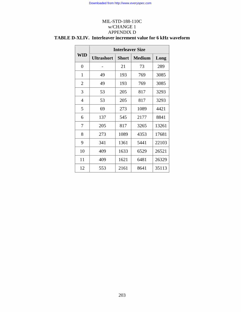
MIL-STD-188-110C
w/CHANGE 1
APPENDIX D
203
TABLE D-XLIV. Interleaver increment value for 6 kHz waveform
WID
Interleaver Size
Ultrashort Short Medium Long
0 - 21 73 289
1 49 193 769 3085
2 49 193 769 3085
3 53 205 817 3293
4 53 205 817 3293
5 69 273 1089 4421
6 137 545 2177 8841
7 205 817 3265 13261
8 273 1089 4353 17681
9 341 1361 5441 22103
10 409 1633 6529 26521
11 409 1621 6481 26329
12 553 2161 8641 35113
Downloaded from http://www.everyspec.com

MIL-STD-188-110C
w/CHANGE 1
APPENDIX D
204
TABLE D-XLV. Interleaver increment value for 9 kHz waveform
WID
Interleaver Size
Ultrashort Short Medium Long
0 - 31 109 433
1 73 289 1153 4645
2 73 289 1153 4645
3 73 289 1153 4645
4 - - - -
5 97 385 1537 6241
6 193 769 3073 12481
7 289 1153 4609 18721
8 385 1537 6145 24961
9 481 1921 7681 31207
10 577 2305 9217 37441
11 811 3241 13771 52651
12 1081 4321 18361 70201
Downloaded from http://www.everyspec.com

MIL-STD-188-110C
w/CHANGE 1
APPENDIX D
205
TABLE D-XLVI. Interleaver increment value for 12 kHz waveform
WID
Interleaver Size
Ultrashort Short Medium Long
0 - 41 145 577
1 73 289 1153 4633
2 73 289 1153 4633
3 97 385 1537 6193
4 97 385 1537 6193
5 129 513 2049 8321
6 257 1025 4097 16641
7 385 1537 6145 24961
8 513 2049 8193 33281
9 641 2561 10241 41603
10 769 3073 13057 49921
11 811 3241 13771 52651
12 1081 4321 18361 70201
Downloaded from http://www.everyspec.com
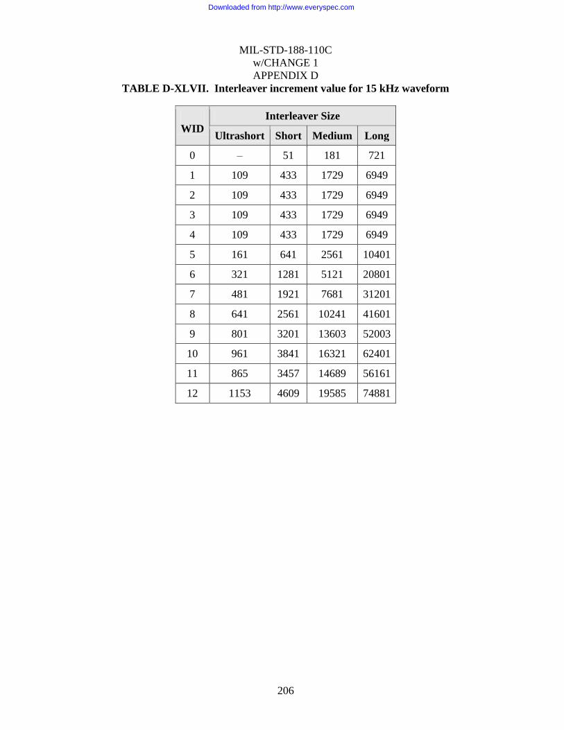
MIL-STD-188-110C
w/CHANGE 1
APPENDIX D
206
TABLE D-XLVII. Interleaver increment value for 15 kHz waveform
WID
Interleaver Size
Ultrashort Short Medium Long
0 – 51 181 721
1 109 433 1729 6949
2 109 433 1729 6949
3 109 433 1729 6949
4 109 433 1729 6949
5 161 641 2561 10401
6 321 1281 5121 20801
7 481 1921 7681 31201
8 641 2561 10241 41601
9 801 3201 13603 52003
10 961 3841 16321 62401
11 865 3457 14689 56161
12 1153 4609 19585 74881
Downloaded from http://www.everyspec.com

MIL-STD-188-110C
w/CHANGE 1
APPENDIX D
207
TABLE D-XLVIII. Interleaver increment value for 18 kHz waveform
WID
Interleaver Size
Ultrashort Short Medium Long
0 - 61 217 865
1 169 673 2689 10811
2 169 673 2689 10811
3 169 673 2689 10811
4 - - - -
5 193 769 3073 12481
6 385 1537 6145 24961
7 577 2305 9217 37441
8 769 3073 13057 49921
9 961 3841 16327 62407
10 1153 4609 19585 74881
11 1441 5761 24481 93601
12 1921 7681 32641 124801
Downloaded from http://www.everyspec.com

MIL-STD-188-110C
w/CHANGE 1
APPENDIX D
208
TABLE D-XLIX. Interleaver increment value for 21 kHz waveform
WID
Interleaver Size
Ultrashort Short Medium Long
0 - 71 253 1009
1 161 641 2561 10281
2 161 641 2561 10281
3 161 641 2561 10281
4 161 641 2561 10281
5 169 673 2689 10921
6 337 1345 5377 21841
7 505 2017 8065 32761
8 673 2689 11425 43681
9 841 3361 14293 54613
10 1009 4033 17137 65521
11 1921 7681 32641 124801
12 2561 10241 43521 166401
Downloaded from http://www.everyspec.com

MIL-STD-188-110C
w/CHANGE 1
APPENDIX D
209
TABLE D-L. Interleaver increment value for 24 kHz waveform
WID
Interleaver Size
Ultrashort Short Medium Long
0 - 81 289 1153
1 137 545 2177 8739
2 137 545 2177 8739
3 205 817 3265 13159
4 205 817 3265 13159
5 273 1089 4353 17681
6 545 2177 8705 35361
7 817 3265 13873 53041
8 1089 4353 18497 70721
9 1361 5441 23123 88403
10 1633 6529 27745 106081
11 1441 5761 24481 93601
12 1921 7681 32641 124801
These increment values have been chosen to ensure that the combined cycles of puncturing and
assignment of bit positions in each symbol for the specific constellation being used is the same
as if there had been no interleaving. For waveforms 7-12, this is important, because each
symbol of a constellation contains “strong” and “weak” bit positions. Bit position refers to the
location of the bit, ranging from MSB to LSB, in the symbol mapping. A strong bit position is
one that has a large average distance between all the constellation points where the bit is a 0
and the closest point where it is a 1. Typically, the MSB is a strong bit and the LSB a weak bit.
An interleaving strategy that does not evenly distribute these bits in the way they occur without
interleaving could degrade performance.
D.5.3.3.3 Interleaver fetch.
The fetching sequence for all data rates and interleaver lengths shall start with location 0 of the
interleaver array and increment the fetch location by 1. This is a simple linear fetch from
beginning to end of the interleaver array.
Downloaded from http://www.everyspec.com

MIL-STD-188-110C
w/CHANGE 1
APPENDIX D
210
D.5.4 Operational features and message protocols.
The format of this high-rate waveform has been designed to permit it to work well with most of
the protocols used and planned for use with HF. The short length of the synchronization
preamble, wide range of interleaving lengths, and the use of full-tail-biting coding is intended
to provide efficient operation with ARQ protocols. To further enhance the operation with these
protocols, the following operational features shall be included in the HF modem.
D.5.4.1 User interfaces.
D.5.4.1.1 Conventional synchronous interface.
A synchronous serial interface shall be provided IAW 4.2.3.
D.5.4.1.2 Conventional asynchronous interface.
In addition to the standard synchronous serial interface (see 4.2.3), the modem shall also be
capable of interfacing with an asynchronous DTE. In this case the DTE provides (accepts)
asynchronous Words consisting of a Start Bit, an N bit Character, and some minimum number
of Stop Bits. Additional Stop Bits are provided (accepted) by the DTE between Words as
necessary to accommodate gaps between their occurrence. Interoperability shall be provided
for those cases where the value of N, the number of Bits in the Character, is 5,6,7, or 8
(including any parity bits), and the minimum number of Stop Bits is 1 or 2. Hence
interoperability is defined for those cases where the number of Bits in the Word is N+2 and
N+3. In these cases the entire N+2 or N+3 bits of the Word shall be conveyed in the modulated
signal. Additional Stop Bits shall be conveyed as necessary to accommodate gaps in data from
the DTE; there shall be no modem-defined null character incorporated into the modulated
signal.
D.5.4.1.3 High speed asynchronous user interface with flow control.
Certain high speed user interfaces provide data to (and accept data from) the modem in units of
8 bit bytes. Furthermore, the Input Data Blocks shown in Tables D-XXXIII through D-XL are
all multiples of 8 bit bytes. An optional mode shall be provided to accommodate the special
case of an 8 bit character (which includes any parity check bits) and a 1.0 unit interval Stop Bit.
In this optional mode, the 8 bit Character shall be aligned with the 256 symbol modem frame
boundary, and no Start or Stop Bits shall be transmitted. In this mode of operation it is assumed
that the DTE data rate is greater than that which can be accommodated by the modem.
Consequently flow control shall be used to temporarily stop data flow from the DTE to the
modem when the modem‟s input buffer becomes full. Conversely, when the modem‟s input
buffer becomes empty, the modem shall assume that the DTE has finished its message, and the
modem shall initiate its normal message-termination procedure. This method of operation
obviates the need for the transmission of Null characters for the purpose of “rate padding.”
Consequently, no Null characters shall be transmitted for this purpose.
D.5.4.1.4 Ethernet interface.
The modem shall provide an Ethernet interface (see Appendix A) for byte oriented user data
transfers (see D.5.4.1.2), and these bytes shall be aligned with the Input Data Block boundaries.
Downloaded from http://www.everyspec.com

MIL-STD-188-110C
w/CHANGE 1
APPENDIX D
211
D.5.4.2 Onset of transmission.
The modem shall begin a transmission no later than 100 ms after it has received an entire input
data block (enough bits to fill a coded and interleaved block), or upon receipt of the last input
data bit, whichever occurs first. The latter would only occur when the message is shorter than
one interleaver block. A transmission shall be defined as beginning with the keying of the
radio, followed by the output of the preamble waveform after the configured pre-key delay, if
any.
The delay between when the modem receives the first input data bit and the onset of
transmission will be highly dependent on the means for delivery of the input data bits to the
modem. A synchronous serial interface at the user data rate will have the greatest delay. For
this reason it is recommended that a high speed asynchronous interface (serial or Ethernet port)
with flow-control be used if this delay is of concern for the deployed application.
D.5.4.3 End of message.
The use of an end-of-message (EOM) in the transmit waveform shall be a configurable option.
When the use of an EOM has been selected, a 32-bit EOM pattern shall be appended after the
last input data bit of the message. The EOM, expressed in hexadecimal notation is 4B65A5B2,
where the left most bit is sent first. If the last bit of the EOM does not fill out an input data
block, the remaining bits in the input data block shall be set to zero before encoding and
interleaving the block.
If the use of an EOM has been inhibited, and the last input data bit does not fill out an input
data block, the remaining bits in the input data block shall be set to zero before encoding and
interleaving the block. It is anticipated that the use of an EOM will only be inhibited when an
ARQ data protocol uses ARQ blocks which completely fill (or nearly so) the selected input
data block size (interleaver block). Without this feature, the use of an EOM would require the
transmission of an additional interleaver block under these circumstances.
D.5.4.4 Termination of a transmission.
Upon receipt of a radio silence (or equivalent) command, the modem shall immediately un-key
the radio and terminate its transmit waveform.
In normal operation, the modem shall terminate a transmission only after the transmission of
the final data frame, including a mini-probe, associated with the final interleaver block. Note
that a data frame consists of a 256 symbol data block followed by a mini-probe. Note that any
signal processing and/or filter delays in the modem and the HF transmitter must be accounted
for (as part of the key line control timing) to ensure that the entire final mini-probe is
transmitted before the transmitter power is turned off.
An optional feature can be added to the end of each transmission. The transmitter can insert an
end-of-transmission (EOT) marker following the last mini-probe sequence. The purpose of this
EOT marker is to allow receiver implementations to detect the end of a transmission
immediately, without having to wait for the EOM marker embedded within the data. The EOT
will not be as robust an indicator of the end of a transmission as the embedded EOM. However,
Downloaded from http://www.everyspec.com
MIL-STD-188-110C
w/CHANGE 1
APPENDIX D
212
in relatively benign channels, this feature will reduce the time before the receiver is able to
return to acquisition mode, with the result that in a TDMA system, back-to-back receptions can
be scheduled with a significantly smaller guard time between them. The EOT shall consist of a
cyclic extension of the last mini-probe, where the mini-probe sequence has been defined in
Table D-XXI. The length of the cyclic extension shall be 13.333 ms (an integer multiple of 32
symbols for each symbol rate). Furthermore, it will be optional for the receiver to search for
this EOT marker, so that operation on challenging multipath fading channels is not affected by
the need to search for EOT marker.
For example, for the length 13 base sequence used with the 3 kHz bandwidth, the last mini-
probe shall consist of the 24 symbols of the last mini-probe, plus 32 additional symbols formed
by the cyclic extension of the 13 symbol Base Sequence. Thus, the final mini-probe will be 56
symbols in length and consist of 4 complete 13 symbol Base sequences plus the first 4 symbols
of a fifth base sequence. This specific example is illustrated in Table D-LI.
Downloaded from http://www.everyspec.com

MIL-STD-188-110C
w/CHANGE 1
APPENDIX D
213
TABLE D-LI. In-phase and Quadrature components of 13 symbol Base Sequence used
to form 24 symbol mini-probe and cyclically extended by 32 symbols to mark the EOT.
Symbol
Number In-Phase Quadrature
Symbol
Number In-Phase Quadrature
0 1.00000 0.0 28 1.00000 0.0
1 1.00000 0.0 29 1.00000 0.0
2 1.00000 0.0 30 1.00000 0.0
3 1.00000 0.0 31 -1.00000 0.0
4 1.00000 0.0 32 -1.00000 0.0
5 -1.00000 0.0 33 1.00000 0.0
6 -1.00000 0.0 34 1.00000 0.0
7 1.00000 0.0 35 -1.00000 0.0
8 1.00000 0.0 36 1.00000 0.0
9 -1.00000 0.0 37 -1.00000 0.0
10 1.00000 0.0 38 1.00000 0.0
11 -1.00000 0.0 39 1.00000 0.0
12 1.00000 0.0 40 1.00000 0.0
13 1.00000 0.0 41 1.00000 0.0
14 1.00000 0.0 42 1.00000 0.0
15 1.00000 0.0 43 1.00000 0.0
16 1.00000 0.0 44 -1.00000 0.0
17 1.00000 0.0 45 -1.00000 0.0
18 -1.00000 0.0 46 1.00000 0.0
19 -1.00000 0.0 47 1.00000 0.0
20 1.00000 0.0 48 -1.00000 0.0
21 1.00000 0.0 49 1.00000 0.0
22 -1.00000 0.0 50 -1.00000 0.0
23 1.00000 0.0 51 1.00000 0.0
24 -1.00000 0.0 52 1.00000 0.0
25 1.00000 0.0 53 1.00000 0.0
26 1.00000 0.0 54 1.00000 0.0
27 1.00000 0.0 55 1.00000 0.0
D.5.4.5 Termination of receive data processing.
There are a number of events which shall cause the HF modem to cease processing the received
signal to recover data, and return to the acquisition mode. These are necessary because a
modem is not able to acquire a new transmission while it is attempting to demodulate and
decode data.
Downloaded from http://www.everyspec.com

MIL-STD-188-110C
w/CHANGE 1
APPENDIX D
214
D.5.4.5.1 Detection of EOM.
The HF modem shall always scan all of the decoded bits for the 32-bit EOM pattern defined in
paragraph 0. Upon detection of the EOM the modem shall return to the acquisition mode. The
modem shall continue to deliver decoded bits to the user (DTE) until the final bit immediately
preceding the EOM has been delivered.
D.5.4.5.2 Command to return to acquisition.
Upon receipt of a command to terminate reception, the HF modem shall return to the
acquisition mode and terminate the delivery of decoded bits to the user (DTE).
D.5.4.5.3 Receipt of a specified number of data blocks.
The maximum message duration measured in number of Input Data Blocks (interleaver blocks)
shall be a configurable parameter. One value of this parameter shall specify that an unlimited
number may be received. Once the modem has decoded and delivered to the user (DTE), the
number of bits corresponding to the configured maximum message duration, the HF modem
shall return to the acquisition mode and terminate the delivery of decoded bits to the user
(DTE). Note that for a given interleaver length, this parameter also specifies the maximum
message duration in time, independent of the bit rate. Note that this parameter is the maximum
duration and that the transmit end always has the option of using an EOM for shorter
transmissions.
Operation with a specified number of input data blocks may be used by an ARQ protocol where
the size of the ARQ packet is fixed, or occasionally changed to accommodate changing
propagation conditions. In this case we anticipate that this parameter (maximum message
duration) will be sent to the receiving end of the link as part of the ARQ protocol. It would
then be sent to the receiving modem through the remote control interface (see 0 below), since it
is not embedded in the waveform itself as the data rate and interleaver length parameters are.
D.5.4.5.4 Initiation of a transmission.
If, and only if, the HF Modem is configured to operate in half-duplex mode with transmit
override, the initiation of a transmission by the user (DTE) shall cause the HF modem to
terminate the receive processing and the delivery of decoded bits to the user (DTE).
D.5.4.6 Remote control.
The remote control interface (see section 5.3.1.5) shall provide the capability to specify the
following parameters and commands:
a. waveform parameters:
1) The bandwidth (from 3kHz through 24 kHz, in multiples of 3 kHz )
2) The waveform ID (0 through 13)
3) The Interleaver length (UltraShort, Short, Medium, or Long)
4) The convolutional code constraint length (7 or 9)
b. A command to select the usage of the optional EOM in the transmit waveform. Note that
the receiving modem must always scan for the EOM regardless of this setting.
Downloaded from http://www.everyspec.com

MIL-STD-188-110C
w/CHANGE 1
APPENDIX D
215
c. A command to specify the maximum message duration measured in number of Input Data
Blocks (interleaver blocks). The value of 0 (zero) for this parameter shall specify that an
unlimited number may be received.
d. A command to cause the modem to terminate receive data processing and return to
acquisition mode.
D.6 PERFORMANCE
All MIL-STD-188-110C modem functionality testing should be performed at baseband. In the
case of testing a modem embedded in an HF Radio, a baseband interface should be utilized if
available. If no baseband interface is provided, care must be taken in the test set up to ensure
that two radios, back to back, deliver a signal to Noise ratio (SNR) significantly higher than the
condition under test so as to not compromise the measurement.
When testing a modem embedded in a radio with no baseband audio interface, the RF signals
must be downconverted to baseband for processing by the channel simulator, and the result
upconverted to RF for the receiver. In this case, transmit gain control (TGC), built-in analog
and digital radio filters and automatic gain control (AGC) will affect the performance of the
modems. Therefore, when testing embedded modems, the SNR values specified in Table D-LII
shall be increased by 3 dB after verifying that the SNR condition mentioned in previous
paragraph is met. Note that the SNR requirement mentioned in previous paragraph must also be
met by the up/down conversion chain with the channel simulator set to non-fading path with 99
dB SNR.
D.6.1 BER performance on AWGN and Multipath Fading Channels
The measured performance of the wideband waveform modes, using fixed-frequency operation
and employing the maximum interleaving period (“Long” interleaver) and a 20-superframe
preamble, shall achieve coded BER of no more than 1.0E-5 under each of the conditions listed
in Table D-LII. Refer to Appendix E for channel simulator requirements. The channel
conditions denoted “Poor Channel” in the tables shall comply with the ITU-R F.1487 Mid-
Latitude-Disturbed Channel.
Downloaded from http://www.everyspec.com

MIL-STD-188-110C
w/CHANGE 1
APPENDIX D
216
TABLE D-LII. Data performance requirements, 3, 6, 9, 12, and 24 kHz Bandwidths.
Waveform Average SNR (dB) for BER ≤ 1.0E-5 Exceptions
Number AWGN Channel “Poor” Channel (for specific bandwidths)
0 -6 -1 9 kHz Poor channel only: allow +1 dB
1 -3 3
2 0 5
3 3 7 9 kHz: allow extra 1 dB (both channels)
4 5 10 this waveform not available in 9 or 18 kHz
5 6 11
6 9 14
7 13 19
8 16 23
9 19 27
10 21 31 24 kHz Poor channel only: test for
BER ≤ 1.0E-4 and allow 33 dB
11 24 -
12 30 -
13 6 11 this waveform available in 3 kHz only
Performance shall be tested using a baseband HF simulator patterned after the Watterson
Model in accordance with Appendix E.
The AWGN channel shall consist of a single, non-fading path. Each condition shall be
measured for at least 60 minutes.
The “Poor” channel shall consist of two independent but equal average power Rayleigh
fading paths, with a fixed 2 ms delay between paths, and with a fading (two sigma)
bandwidth (BW) of 1 Hz. Each condition shall be measured for at least 5 hours.
To compute SNR, both signal and noise power shall be measured in the specified
bandwidth.
When testing a modem embedded with a radio, so that only radio frequency (RF) signals are
available for testing, the RF signals must be downconverted to baseband for processing by the
channel simulator, and the result upconverted to RF for the receiver. In this case, the built-in
radio filters will affect the performance of the modems. Therefore, when testing embedded
modems, the SNR values specified in Table D-LII shall be increased by 2 dB (3 dB at 9600 bps
and above).
When the sending and receiving modems used in this test are not identical make and model, an
extra dB of SNR shall be allowed due to potential degradation in mismatched filters.
D.6.2 BER performance on static multipath channels
The measured performance of the wideband waveform modes, using fixed-frequency operation
and employing the maximum interleaving period (“Long” interleaver), shall achieve coded
Downloaded from http://www.everyspec.com

MIL-STD-188-110C
w/CHANGE 1
APPENDIX D
217
BER of no more than 1.0E-5 for an SNR of 50 dB under the static multipath channel conditions
shown in Table D-LIII. For all the static channels defined in table, all paths have equal power.
The test period for each test should be 10 minutes. Due to possible alignment issues when
acquiring channels with large delay spread, up to 3 opportunities are allowed per test to achieve
a BER < 1e-5. Table shows the delay in milliseconds (ms) between the equal-power paths. For
example, for WID 2 in 3 kHz, the second path is delayed 3.0 ms from the first path, and the
third is delayed 9.0 ms from the first path.
TABLE D-LIII. Static Channel Tests
Bandwidth WID
Multipath Channel Delays
(ms)
3 KHz
2 3-Path (0.0, 3.0, 9.0)
10 3-Path (0.0, 2.0, 4.5)
12 2-Path (0.0, 1.5)
6 KHz
2 3-Path (0.0, 2.0, 9.0)
10 4-Path (0.0, 1.5, 3.0, 5.0)
12 2-Path (0.0, 1.5)
9 KHz
3 3-Path (0.0, 3.0, 8.0)
10 3-Path (0.0, 2.0, 4.5)
12 2-Path (0.0, 1.5)
12 KHz
2 3-Path (0.0, 2.5, 8.5)
10 4-Path (0.0, 1.5, 3.0, 5.0)
12 2-Path (0.0, 1.5)
24 KHz
5 3-Path (0.0, 2.5, 5.5)
10 4-Path (0.0, 1.5, 3.0, 5.0)
12 2-Path (0.0, 1.5)
D.6.3 Acquisition performance.
Not yet standardized.
D.6.4 Doppler shift test.
The modem shall acquire and maintain synchronization in 3, 6, 9, 12, and 24 kHz channels for
at least 5 minutes with a test signal having the following characteristics: WID 10/Long
interleaver, 75 Hz frequency offset, 2 ms delay spread, a fading BW of 1 Hz, and an average
Downloaded from http://www.everyspec.com

MIL-STD-188-110C
w/CHANGE 1
APPENDIX D
218
SNR of 30 dB. The test shall be repeated with a –75 Hz frequency offset. No BER test is
required.
D.6.5 Doppler sweep performance.
The AWGN BER test for WID 10 shall be repeated in 3, 6, 9, 12, and 24 kHz channels with a
test signal having a frequency offset that continuously varies at a rate of 3.5 Hz/s between the
limits of -75 and +75 Hz, such that a plot of frequency offset vs. time describes a periodic
“triangle” waveform having a period of (300/3.5) seconds. Over a test duration of 1 hour, the
modem shall achieve a BER of 1.0E-5 or less at an SNR of 24 dB.
D.7 ASSOCIATED COMMUNICATIONS EQUIPMENT
The QAM constellations specified in this appendix are more sensitive to equipment variations
than the PSK constellations specified in section 5.3.2 of this standard. Because of this
sensitivity, radio filters will have a significant impact on the performance of modems
implementing the waveforms in this appendix. In addition, because of the level sensitive nature
of the QAM constellations, turn-on transients, AGC, and ALC can cause significant
performance degradation.
It is recommended that external modems (i.e., modems not integrated with the radio)
implementing the waveforms in this appendix should include a variable pre-key feature, by
which the user can specify a delay between the time when the transmitter is keyed and the
modem signal begins. This allows for turn-on transient settling, which is particularly important
for legacy radio equipment.
It is recommended that a slow AGC setting (e.g., the “nondata” mode in MIL-STD-188-141) be
used when receiving the waveforms in this appendix.
Downloaded from http://www.everyspec.com

MIL-STD-188-110C
w/CHANGE 1
APPENDIX E
218
CHARACTERISTICS OF HF CHANNEL SIMULATORS
TABLE OF CONTENTS
PARAGRAPH PAGE
E.1 GENERAL........................................................................................................................................ 220
E.1.1 Scope. .............................................................................................................................. 220
E.1.2 Applicability. ................................................................................................................... 220
E.2 APPLICABLE DOCUMENTS....................................................................................................... 220
E.2.1 Non-government documents. .......................................................................................... 220
E.2.2 Order of precedence. ....................................................................................................... 220
E.3 DEFINITIONS ................................................................................................................................. 220
E.4 GENERAL REQUIREMENTS ...................................................................................................... 221
E.4.1 Watterson Channel Model ............................................................................................... 221
E.4.2 Implementation of the Watterson HF Channel Model .................................................... 221
E.4.3 Radio Filters .................................................................................................................... 222
E.4.4 Latency ............................................................................................................................ 222
E.5 DETAILED REQUIREMENTS ..................................................................................................... 222
E.5.1 Sample rate. ..................................................................................................................... 222
E.5.2 Delay spread simulation .................................................................................................. 222
E.5.3 White gaussian noise generation. .................................................................................... 222
E.5.4 Fading tap gain generation. ............................................................................................. 222
E.5.5 Signal-to-noise ratio ........................................................................................................ 223
E.6 IMPLEMENTATION DETAILS FOR WIDEBAND HF CHANNEL SIMULATORS ........... 224
E.6.1 Analog interface .............................................................................................................. 224
E.6.2 Hilbert Transform Alternative ......................................................................................... 224
E.6.3 Output LPF ...................................................................................................................... 224
E.7 CHANNEL SIMULATOR VALIDATION .................................................................................. 225
E.7.1 Bandwidth ........................................................................................................................ 225
E.7.2 Signal-to-noise ratio – Single Non-fading path ............................................................... 225
E.7.3 Signal-to-noise ratio – Single fading path ....................................................................... 225
E.7.4 Doppler Spectrum ............................................................................................................ 225
Downloaded from http://www.everyspec.com
MIL-STD-188-110C
w/CHANGE 1
APPENDIX E
219
FIGURES
FIGURE PAGE
FIGURE E-1. IMPLEMENTATION OF THE WATTERSON HF CHANNEL MODEL ............ 221
FIGURE E-2. FADING TAP GAIN GENERATION ...................................................................... 223
FIGURE E-3. DOPPLER SPECTRUM ........................ ERROR! BOOKMARK NOT DEFINED.
Downloaded from http://www.everyspec.com

MIL-STD-188-110C
w/CHANGE 1
APPENDIX E
220
E.1 SCOPE
E.1.1 Scope.
This appendix describes the characteristics of baseband HF channel simulators to be used in
performance testing of modems that are intended for use in HF channels up to 24 kHz
(nominally N x 3 kHz, where N is 1, 2, 3, 4, 5, 6, 7, or 8).
E.1.2 Applicability.
This appendix is a nonmandatory part of MIL-STD-188-110B; however, channel simulators
used to evaluate the compliance of modems with the performance requirements of this standard
shall comply with this appendix.
E.2 APPLICABLE DOCUMENTS
E.2.1 Non-government documents.
The following documents form a part of this document to the extent specified herein..
1. C. C. Watterson, J. R. Juroshek, W. D. Bensema, “Experimental Confirmation of an HF
Channel Model”, IEEE Transactions On Communications Technology, Vol. COM-18,
No. 6, Dec. 1970
2. Michel C. Jeruchim, Philip Balaban, and K. Sam Shanmugan, “Simulation of
Communication Systems”, ISBN 0-306-43989-1, Plenum Publishing
3. W. N. Furman, J. W. Nieto, “Understanding HF Channel Simulator Requirements in
Order to Reduce HF Modem Performance measurement Variability,” Proceedings of
HF01, Nordic HF Conference, Faro, Sweden, August 2001.
E.2.2 Order of precedence.
In the event of a conflict between the text of this document and the references cited herein, the
text of this document takes precedence. Nothing in this document, however, supersedes
applicable laws and regulations unless specific exemption has been obtained.
DEFINITIONS
See section 3.
Downloaded from http://www.everyspec.com

MIL-STD-188-110C
w/CHANGE 1
APPENDIX E
221
E.4 GENERAL REQUIREMENTS
E.4.1 Watterson Channel Model
The model of the HF channel to be implemented in simulators specified in this Appendix is the
two-path model originally described by Watterson, et al, in “Experimental Confirmation of an
HF Channel Model”, IEEE Transactions On Communications Technology, Vol. COM-18, No. 6, Dec. 1970. In this model, the output of the channel consists of white Gaussian noise (WGN) added to two copies of the input signal which are delayed relative to each other by a fixed amount (the “delay spread”). The amplitudes of the two delayed copies of the input signal vary according to independent fading gains which have Gaussian power spectral densities with a specified “fading bandwidth.” The two paths have equal power, averaged over a long period.
The Watterson model of a channel is completely specified by three parameters: the delay
spread, the fading bandwidth per path, and the average signal-to-noise ratio (SNR) of the
received signal.
E.4.2 Implementation of the Watterson HF Channel Model
The Watterson model shall be implemented using a tap-delay line as shown in Figure E-1.
xi-1 xi-L-2 xi-2 xi
ni
+
z -1
xi-L-1
z -1
z -1
z -1
h0 h1 h2 hL-2 hL-1
yi
Figure E-1. Implementation of the Watterson HF Channel Model
The input xi, output yi, noise ni, and filter tap gains hj are complex, time-varying quantities; i is
the time index. For a two-path model with fixed delay spread, only two of the tap gains shall
be non-zero: h0 and hL-1, where L is the specified delay spread of the channel divided by the
sampling period. Mathematically, the relationship among these quantities is as follows:
tektf dt
j ,2222
Downloaded from http://www.everyspec.com

MIL-STD-188-110C
w/CHANGE 1
APPENDIX E
222
NOTE: when the external input to the channel simulator is a real audio signal, a Hilbert
transform may be used to create the complex signal xi.
NOTE: since the external output from the channel simulator is a real audio signal, only the real
part of the resulting output signal yi is output.
E.4.3 Radio Filters
If radio filters are implemented within the channel simulator, they shall be disabled when the
simulator is used for testing compliance with the performance requirements in this standard.
E.4.4 Latency
Delay through the channel simulator (xi to yi) shall not exceed 25 ms (DO: 10 ms) when the
simulator is used to test two-way (interactive) systems.
E.5 DETAILED REQUIREMENTS
NOTE: “Simulation of Communication Systems,” by Jeruchim, et al, and “Understanding HF
Channel Simulator Requirements in Order to Reduce HF Modem Performance measurement
Variability,” by Furman and Nieto are useful references for implementers of channel
simulators.
E.5.1 Sample rate.
The sample rate of the simulator shall be at least four times the symbol rate of the anticipated
modem waveform to test. For example 9600 samples per second for the 3kHz bandwidth
waveforms specified in Appendix C and 76800 samples per second for the 24kHz bandwidth
waveforms specified in Appendix D.
The crystal used to generate the sample rate should be specified to drift no more than 500 parts
per million (PPM) over its operating temperature range.
E.5.2 Delay spread simulation
The length of the simulated channel, L, shall be computed as the specified delay spread divided
by the sample rate, and rounded to the nearest integer.
E.5.3 White gaussian noise generation.
The white noise generated for use in producing the channel noise (ni in Figure E-1) and the
fading gains (h0 and hL-1 in Figure E-1) shall be independent random processes with power
spectra that are uniform within ±1 dB up to the sampling rate /2.
E.5.4 Fading tap gain generation.
Fading tap gains (see Figure E-1) shall be obtained by filtering complex white Gaussian noise
samples as shown in Figure E-2.
Downloaded from http://www.everyspec.com
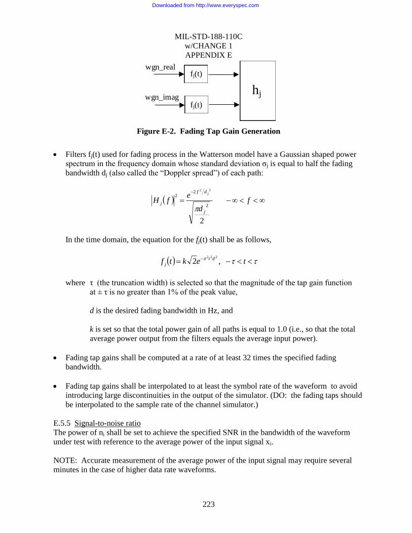
MIL-STD-188-110C
w/CHANGE 1
APPENDIX E
223
wgn_imag
wgn_real fj(t)
fj(t)
hj
Figure E-2. Fading Tap Gain Generation
Filters fj(t) used for fading process in the Watterson model have a Gaussian shaped power
spectrum in the frequency domain whose standard deviation σj is equal to half the fading
bandwidth dj (also called the “Doppler spread”) of each path:
fd
efH
j
df
j
j
2
2
22
22
In the time domain, the equation for the fj(t) shall be as follows,
tektf dt
j ,2222
where τ (the truncation width) is selected so that the magnitude of the tap gain function
at ± τ is no greater than 1% of the peak value,
d is the desired fading bandwidth in Hz, and
k is set so that the total power gain of all paths is equal to 1.0 (i.e., so that the total
average power output from the filters equals the average input power).
Fading tap gains shall be computed at a rate of at least 32 times the specified fading
bandwidth.
Fading tap gains shall be interpolated to at least the symbol rate of the waveform to avoid
introducing large discontinuities in the output of the simulator. (DO: the fading taps should
be interpolated to the sample rate of the channel simulator.)
E.5.5 Signal-to-noise ratio
The power of ni shall be set to achieve the specified SNR in the bandwidth of the waveform
under test with reference to the average power of the input signal xi.
NOTE: Accurate measurement of the average power of the input signal may require several
minutes in the case of higher data rate waveforms.
Downloaded from http://www.everyspec.com

MIL-STD-188-110C
w/CHANGE 1
APPENDIX E
224
E.6. IMPLEMENTATION DETAILS FOR WIDEBAND HF CHANNEL SIMULATORS
E.6.1 Analog interface
The analog interface is of primary concern, especially for wideband HF waveform testing and
evaluation. It should be noted that many PC soundcards have an analog filter on the audio
input between 20 kHz and 24 kHz. Care should be taken to make sure that the pass band of the
channel simulator is consistent with the waveform bandwidths to be tested.
An additional factor for consideration for wideband testing is the center or subcarrier frequency
of the waveform under test. It may be beneficial to have the interface implemented at a
common subcarrier frequency, for example 19.2 kHz, where all modem waveforms,
independent of their bandwidth, would be centered at 19.2 kHz.
The sample rate of the simulator shall be at least four times the symbol rate of the anticipated
modem waveform to test. For example 9600 samples per second for the 3kHz bandwidth
waveforms specified in Appendix C and 76800 samples per second for the 24kHz bandwidth
waveforms specified in Appendix D.
E.6.2 Hilbert Transform Alternative
Baseband channel simulators generally employ a Hilbert transform to generate a complex
baseband equivalent signal, from the real input signal in order to easily implement the
amplitude and phase variations of the fading multipath channel. Hilbert transforms are often
implemented as an FIR filter. As the sample rate is increased to support wider bandwidth
signals the lower limit of the Hilbert pass band also increased, possibly to a point that would
impact the lower frequencies of the modem waveform.
An alternate Hilbert architecture can be implemented by an overlapped FFT approach, where
the phase and gain properties of the Hilbert transform are implemented in the frequency domain
and an inverse FFT is utilized to return the signal to the time domain.
E.6.3 Output LPF
Depending on the analog interface of the output of the channel simulator it may be beneficial to
have a low-pass or band-pass filter that is slightly wider than the waveform signal under test.
This will prevent the wider bandwidth noise signal, which may be present because of the higher
sampling rate, from causing any aliasing issues with the waveform receive hardware.
A low-pass or band-pass filter can easily be implemented by an overlapped FFT approach
similar in nature to the Hilbert transform described above.
Downloaded from http://www.everyspec.com
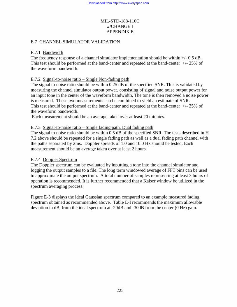
MIL-STD-188-110C
w/CHANGE 1
APPENDIX E
225
E.7 CHANNEL SIMULATOR VALIDATION
E.7.1 Bandwidth
The frequency response of a channel simulator implementation should be within +/- 0.5 dB.
This test should be performed at the band-center and repeated at the band-center +/- 25% of
the waveform bandwidth.
E.7.2 Signal-to-noise ratio – Single Non-fading path
The signal to noise ratio should be within 0.25 dB of the specified SNR. This is validated by
measuring the channel simulator output power, consisting of signal and noise output power for
an input tone in the center of the waveform bandwidth. The tone is then removed a noise power
is measured. These two measurements can be combined to yield an estimate of SNR.
This test should be performed at the band-center and repeated at the band-center +/- 25% of
the waveform bandwidth.
Each measurement should be an average taken over at least 20 minutes.
E.7.3 Signal-to-noise ratio – Single fading path, Dual fading path
The signal to noise ratio should be within 0.5 dB of the specified SNR. The tests described in H
7.2 above should be repeated for a single fading path as well as a dual fading path channel with
the paths separated by 2ms. Doppler spreads of 1.0 and 10.0 Hz should be tested. Each
measurement should be an average taken over at least 2 hours.
E.7.4 Doppler Spectrum
The Doppler spectrum can be evaluated by inputting a tone into the channel simulator and
logging the output samples to a file. The long term windowed average of FFT bins can be used
to approximate the output spectrum. A total number of samples representing at least 3 hours of
operation is recommended. It is further recommended that a Kaiser window be utilized in the
spectrum averaging process.
Figure E-3 displays the ideal Gaussian spectrum compared to an example measured fading
spectrum obtained as recommended above. Table E-I recommends the maximum allowable
deviation in dB, from the ideal spectrum at -20dB and -30dB from the center (0 Hz) gain.
Downloaded from http://www.everyspec.com
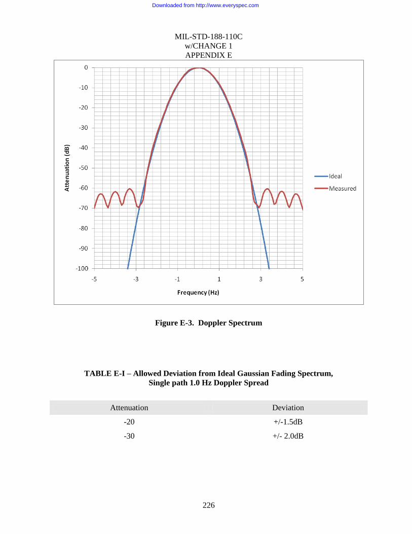
MIL-STD-188-110C
w/CHANGE 1
APPENDIX E
226
Figure E-3. Doppler Spectrum
TABLE E-I – Allowed Deviation from Ideal Gaussian Fading Spectrum,
Single path 1.0 Hz Doppler Spread
Attenuation Deviation
-20 +/-1.5dB
-30 +/- 2.0dB
Downloaded from http://www.everyspec.com

MIL-STD-188-110C
W/CHANGE 1
APPENDIX F
227
HF DATA MODEMS FOR MULTIPLE CHANNEL SYSTEMS
TABLE OF CONTENTS
PARAGRAPH .................................................................................................................................. PAGE
F.1 GENERAL .................................................................................................................................... 229
F.1.1 Scope. .......................................................................................................................................... 229
F.1.2 Applicability. .............................................................................................................................. 229
F.2 APPLICABLE DOCUMENTS ................................................................................................... 229
F.3 DEFINITIONS .............................................................................................................................. 229
F.4 GENERAL REQUIREMENTS ................................................................................................... 229
F.4.1 Architectures for multiple channel operation. ........................................................................... 229
F.4.1.1 Multiple channel operation with independent-sideband modem. ..........................................229
F.4.1.2 Multiple channel operation with multiple modems. (Optional) ............................................230
F.4.1.3 Multiple channel operation with parallel ARQ channels. (Optional) ...................................231
F.4.2 HF data modem waveform for two-independent-sideband applications. ................................ 231
F.5 DETAILED REQUIREMENTS .................................................................................................. 232
F.5.1 Modulation. ................................................................................................................................. 232
F.5.1.1 Known symbols. .......................................................................................................................232
F.5.1.2 Data symbols. ...........................................................................................................................233
F.5.1.3 PSK data symbols. ...................................................................................................................233
F.5.1.6 QAM data symbols. .................................................................................................................233
F.5.1.7 The 16 QAM constellation. .....................................................................................................233
F.5.1.8 The 32 QAM constellation. .....................................................................................................233
F.5.1.9 The 64QAM constellation. ......................................................................................................234
F.5.1.10 Data scrambling. .....................................................................................................................234
F.5.2 Frame structure. .......................................................................................................................... 234
F.5.3 Coding and interleaving. ............................................................................................................ 235
F.5.3.1 Block boundary alignment. ......................................................................................................236
F.5.3.2 Block encoding. ........................................................................................................................236
F.5.3.3 Block interleaver structure. ......................................................................................................236
F.5.3.4 Interleaver size in bits. ..............................................................................................................236
F.5.3.5 Interleaver load. ........................................................................................................................236
F.5.3.6 Interleaver fetch. .......................................................................................................................237
F.5.4 Operational features and message protocols. ............................................................................ 237
F.6 PERFORMANCE ......................................................................................................................... 237
F.7 ASSOCIATED COMMUNICATIONS EQUIPMENT ............................................................. 238
Downloaded from http://www.everyspec.com
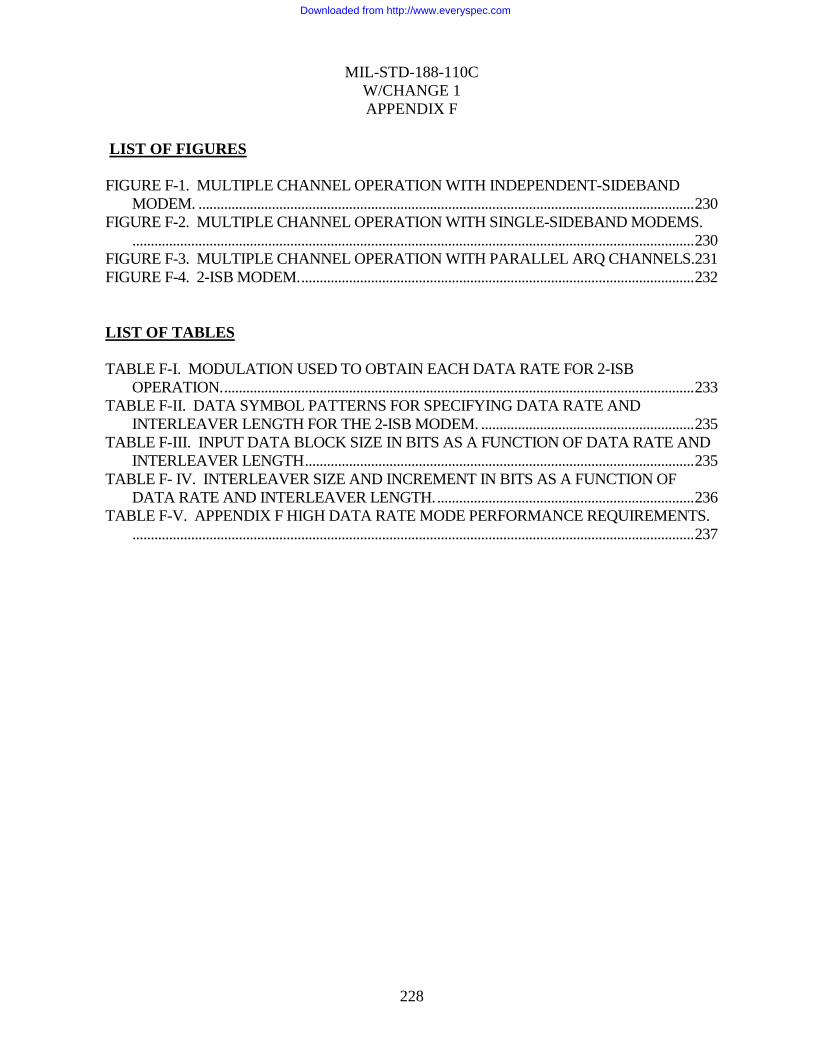
MIL-STD-188-110C
W/CHANGE 1
APPENDIX F
228
LIST OF FIGURES
FIGURE F-1. MULTIPLE CHANNEL OPERATION WITH INDEPENDENT-SIDEBAND
MODEM. ....................................................................................................................................... 230
FIGURE F-2. MULTIPLE CHANNEL OPERATION WITH SINGLE-SIDEBAND MODEMS.
......................................................................................................................................................... 230
FIGURE F-3. MULTIPLE CHANNEL OPERATION WITH PARALLEL ARQ CHANNELS. 231
FIGURE F-4. 2-ISB MODEM. ........................................................................................................... 232
LIST OF TABLES
TABLE F-I. MODULATION USED TO OBTAIN EACH DATA RATE FOR 2-ISB
OPERATION. ................................................................................................................................ 233
TABLE F-II. DATA SYMBOL PATTERNS FOR SPECIFYING DATA RATE AND
INTERLEAVER LENGTH FOR THE 2-ISB MODEM. .......................................................... 235
TABLE F-III. INPUT DATA BLOCK SIZE IN BITS AS A FUNCTION OF DATA RATE AND
INTERLEAVER LENGTH .......................................................................................................... 235
TABLE F- IV. INTERLEAVER SIZE AND INCREMENT IN BITS AS A FUNCTION OF
DATA RATE AND INTERLEAVER LENGTH. ...................................................................... 236
TABLE F-V. APPENDIX F HIGH DATA RATE MODE PERFORMANCE REQUIREMENTS.
......................................................................................................................................................... 237
Downloaded from http://www.everyspec.com

MIL-STD-188-110C
W/CHANGE 1
APPENDIX F
229
F.1 SCOPE
F.1.1 Scope.
This appendix describes HF data modem operation over multiple discrete channels (including
independent sidebands of a single carrier), and specifies a waveform that supports data rates of
9600 to 19,200 bps over two-independent-sideband (2-ISB) radios using the waveforms from
Appendix C.
F.1.2 Applicability.
This appendix is a nonmandatory part of MIL-STD-188-110B; however, systems using HF data
modem waveforms on multiple discrete channels shall operate in accordance with this
appendix.
F.2 APPLICABLE DOCUMENTS
This section is not applicable to this appendix.
F.3 DEFINITIONS
See section 3.
F.4 GENERAL REQUIREMENTS
The use of multiple HF channels in parallel can provide data throughput greater than the use of
a single sideband channel. Section F.4.1 describes a range of architectures for multiple channel
operation that may be useful in specific applications. Section 0 describes an independent
sideband (ISB) modem waveform that may be used in any of these architectures.
F.4.1 Architectures for multiple channel operation.
F.4.1.1 Multiple channel operation with independent-sideband modem.
When ISB radios and channel allocations are available, the channels provided by the radio
inherently have similar channel characteristics, and can support similar data rates. A modem
that spreads coded symbols over the available channels takes full advantage of this capability.
Such a modem is shown in Figure F-1 (with optional link-level encryption). The two-channel
ISB (2-ISB) modem specified in sections 0 and 0 is the mandatory portion of this appendix.
The ISB capability is currently limited to two channels per modem. Four-channel radios
support two such 2-ISB modems using either of the techniques described in the following
sections.
Downloaded from http://www.everyspec.com

MIL-STD-188-110C
W/CHANGE 1
APPENDIX F
230
FIGURE F-1. Multiple channel operation with independent-sideband modem.
F.4.1.2 Multiple channel operation with multiple modems. (Optional)
When ISB radios and channel allocations are available, but ISB modems with a matching
number of audio channels are not available, multiple modems may be employed as shown in
Figure F-2. The upper diagram illustrates the case of unencrypted user data and link-level
encryption (as in the previous section). The lower diagram depicts application-layer (end-to-
end) encryption.
FIGURE F-2. Multiple channel operation with single-sideband modems.
The first bit of data to be sent shall be delivered to the modem associated with the highest over-
the-air frequency, with succeeding bits delivered to modems with decreasing frequencies.
When M modems are attached to a single ISB radio (M = 2 shown), all modems shall operate at
a single data rate, and modem i (i = 0 .. M - 1) shall carry bits numbered i + nM (n = 0, 1,…).
This architecture also may be applied to multiple radios operating on unrelated frequencies.
However, performance may not be satisfactory if the characteristics of the various channels are
not sufficiently similar to support a common maximum data rate. Bit ordering shall be as
specified above, with the identity of the modem associated with the highest over-the-air
frequency determined when the link is initially established, regardless of subsequent frequency
changes while linked.
ISBRadio
Modulator
Modulator
FECARQ
Modem
Traffic Manager
User Data MuxCrypto
ISBRadio
ARQTraffic
Manager
Encrypted Data
ISBRadio
ARQTraffic
Manager
User Data Crypto Mux
Mux
Control
SSB or ISB Modem
•••
SSB or ISB Modem
SSB or ISB Modem
•••
SSB or ISB Modem
Downloaded from http://www.everyspec.com

MIL-STD-188-110C
W/CHANGE 1
APPENDIX F
231
In the bit-synchronous approach described above, it is understood that the multiplexer and
modems share a common clock. In addition, the multiplexer provides a short synchronization
header in the bit stream to each modem prior to the payload data. Note that this header is
transparent to the ARQ or other modem-user process. The header is used by the multiplexer at
the receive end to establish bit-order integrity. This header is required since a bit-synchronous
Tx modem interface does not generally guarantee that the first bit out of the receiving modem
is the first bit out of the transmitting DTE following assertion of CTS.
Alternatively, the High Speed Asynchronous Interface with Flow Control that is described in
section C.5.4.1 may be used. In this case, data to successive modems from the multiplexer will
be successive bytes rather than successive bits.
F.4.1.3 Multiple channel operation with parallel ARQ channels. (Optional)
The architecture shown in Figure F-3 accommodates any combination of radios and modems
for multiple-channel operation. As above, the upper diagram illustrates link-level encryption
while the lower diagram depicts application-layer (end-to-end) encryption.
FIGURE F-3. Multiple channel operation with parallel ARQ channels.
A traffic manager process dynamically assigns packets to a separate ARQ protocol process
associated with each modem. Each ARQ process adapts its modem‟s data rate to the channel
conditions it encounters; the traffic manager likewise adapts the rate that it assigns packets to
the ARQ processes based on their completion rates. Message reassembly relies on packet
offset fields in the packet headers.
F.4.2 HF data modem waveform for two-independent-sideband applications.
This appendix presents a modem waveform and coding specification for data transmission over
two HF sidebands for data rates from 9.6 up to 19.2 kbps. As in Appendix C, a block
interleaver is used to obtain 6 interleaving lengths ranging from 0.12 s to 8.64 s. The
Radio(s)
ARQ SSB or ISB Modem
Traffic Manager
ARQ
User Data
•••
•••
•••
Crypto
Crypto
Radio(s)
ARQ
Modems
Traffic Manager
ARQ
•••
•••
•••
Encrypted Data
Control
SSB or ISB Modem
SSB or ISB Modem
SSB or ISB Modem
Downloaded from http://www.everyspec.com
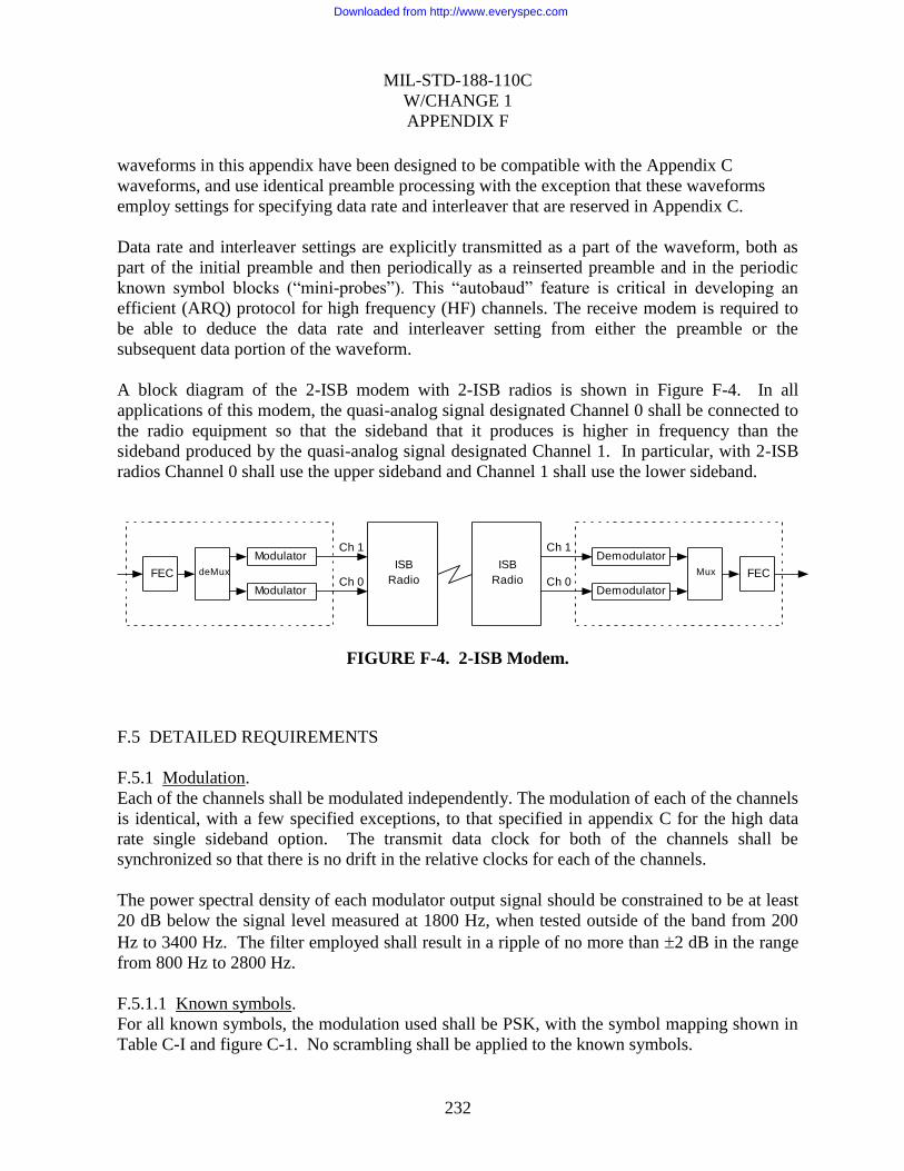
MIL-STD-188-110C
W/CHANGE 1
APPENDIX F
232
waveforms in this appendix have been designed to be compatible with the Appendix C
waveforms, and use identical preamble processing with the exception that these waveforms
employ settings for specifying data rate and interleaver that are reserved in Appendix C.
Data rate and interleaver settings are explicitly transmitted as a part of the waveform, both as
part of the initial preamble and then periodically as a reinserted preamble and in the periodic
known symbol blocks (“mini-probes”). This “autobaud” feature is critical in developing an
efficient (ARQ) protocol for high frequency (HF) channels. The receive modem is required to
be able to deduce the data rate and interleaver setting from either the preamble or the
subsequent data portion of the waveform.
A block diagram of the 2-ISB modem with 2-ISB radios is shown in Figure F-4. In all
applications of this modem, the quasi-analog signal designated Channel 0 shall be connected to
the radio equipment so that the sideband that it produces is higher in frequency than the
sideband produced by the quasi-analog signal designated Channel 1. In particular, with 2-ISB
radios Channel 0 shall use the upper sideband and Channel 1 shall use the lower sideband.
FIGURE F-4. 2-ISB Modem.
F.5 DETAILED REQUIREMENTS
F.5.1 Modulation.
Each of the channels shall be modulated independently. The modulation of each of the channels
is identical, with a few specified exceptions, to that specified in appendix C for the high data
rate single sideband option. The transmit data clock for both of the channels shall be
synchronized so that there is no drift in the relative clocks for each of the channels.
The power spectral density of each modulator output signal should be constrained to be at least
20 dB below the signal level measured at 1800 Hz, when tested outside of the band from 200
Hz to 3400 Hz. The filter employed shall result in a ripple of no more than 2 dB in the range
from 800 Hz to 2800 Hz.
F.5.1.1 Known symbols.
For all known symbols, the modulation used shall be PSK, with the symbol mapping shown in
Table C-I and figure C-1. No scrambling shall be applied to the known symbols.
Modulator
Modulator
FEC deMux
Ch 1
Ch 0
ISB
Radio
ISB
Radio
Ch 1
Ch 0
Demodulator
Demodulator
Mux FEC
Downloaded from http://www.everyspec.com

MIL-STD-188-110C
W/CHANGE 1
APPENDIX F
233
F.5.1.2 Data symbols.
For data symbols, the modulation used depends upon the data rate as shown in Table F-I.
TABLE F-I. Modulation used to obtain each data rate for 2-ISB operation.
Modulation Code Rate Data Rate (kbps)
8PSK 3/4 9.6
16QAM 3/4 12.8
32QAM 3/4 16.0
64QAM 3/4 19.2
F.5.1.3 PSK data symbols.
For the PSK constellations, a distinction is made between the data bits and the symbol number.
Transcoding is an operation which links a symbol to be transmitted to a group of data bits.
F.5.1.4 QPSK symbol mapping.
For QPSK symbols, used in the preamble and reinserted preamble to specify data rate and
interleaving, transcoding shall be achieved by linking one of the symbols specified in Table C-I
to a set of two consecutive data bits (dibit) as shown in Table C-III. In this Table, the leftmost
bit of the dibit shall be the older bit; i.e., fetched from the interleaver before the rightmost bit.
F.5.1.5 8PSK symbol mapping.
For the 9600 bps user data rate, transcoding shall be achieved by linking one symbol to a set of
three consecutive data bits (tribit) as shown in Table C-IV. In this Table, the leftmost bit of the
tribit shall be the oldest bit; i.e., fetched from the interleaver before the other two, and the
rightmost bit is the most recent bit.
F.5.1.6 QAM data symbols.
For the QAM constellations, no distinction is made between the number formed directly from
the data bits and the symbol number. Each set of 4 bits (16QAM), 5 bits (32QAM) or 6 bits
(64QAM) is mapped directly to a QAM symbol. For example, the four bit grouping 0111
would map to symbol 7 in the 16QAM constellation while the 6 bit grouping 100011 would
map to symbol 35 in the 64QAM constellation. Again, in each case the leftmost bit shall be the
oldest bit, i.e. fetched from the interleaver before the other bits, and the rightmost bit is the
most recent bit.
F.5.1.7 The 16 QAM constellation.
See figure C-2 and Table C-V.
F.5.1.8 The 32 QAM constellation.
See figure C-3 and Table C-VI.
Downloaded from http://www.everyspec.com

MIL-STD-188-110C
W/CHANGE 1
APPENDIX F
234
F.5.1.9 The 64QAM constellation.
See figure C-4 and Table C-VII.
F.5.1.10 Data scrambling.
Data symbols for the 8PSK symbol constellation shall be scrambled by modulo 8 addition with
a scrambling sequence. The data symbols for the 16QAM, 32QAM, and 64QAM constellations
shall be scrambled by using an exclusive or (XOR) operation. Sequentially, the data bits
forming each symbol (4 for 16QAM, 5 for 32QAM, and 6 for 64QAM) shall be XOR‟d with an
equal number of bits from the scrambling sequence. In all cases, the scrambling sequence
generator polynomial shall be x9 +x4 +1 and the generator shall be initialized to 1 at the start of
each data frame. A block diagram of the scrambling sequence generator is shown in figure C-5.
Further details of the operation of the data scrambler may be found in C.5.1.3.
F.5.2 Frame structure.
The frame structure shall be as described in C.5.2 except that the data symbols D0, D1, and D2
(used in the preambles and encoded in the mini-probes) take on values distinct from those used
for the Appendix C SSB modes.
For the two sideband option, the 3 bits used for data rate in SSB are fixed at 000. The bits
normally used for interleaver setting in SSB are employed as specified in Table F-II, using both
channels, to select data rate and interleaver settings. Channel 0 carries the code for the
combined data rate and Channel 1 carries the code for the common interleaver. Recall that
channel 0 is always the higher frequency of the two sidebands. Unused codings are reserved
and shall not be used until standardized.
Downloaded from http://www.everyspec.com

MIL-STD-188-110C
W/CHANGE 1
APPENDIX F
235
TABLE F-II. Data symbol patterns for specifying data rate and interleaver length for the
2-ISB modem.
Channel 0
Data Rate (kbps) D0,D1,D2 3 Bit Mapping
9.6 0,0,2 001
12.8 0,2,0 010
16.0 0,2,2 011
19.2 2,0,0 100
Channel 1
Interleaver D0,D1,D2 3 Bit Mapping
Ultra Short 0,0,2 001
Very Short 0,2,0 010
Short 0,2,2 011
Medium 2,0,0 100
Long 2,0,2 101
Very Long 2,2,0 110
F.5.3 Coding and interleaving.
The interleaver used shall be a block interleaver. Each block of input data shall be encoded
using a block encoding technique with a code block size equal to the size of the block
interleaver. Thus, the input data bits will be sent as successive blocks of bits on both channels
that together span the duration of the interleaver length selected.
Table F-III shows the number of input data bits per block as function of both data rate and
interleaver length. Note that an “input data block” should not be confused with the 256 symbol
data block that is part of a data frame in the waveform format. The bits from an input data
block will be mapped through the coding and interleaving to the number of data frames, and
thus 256 symbol data blocks, that define the interleaver length.
TABLE F-III. Input data block size in bits as a function of data rate and interleaver
length
Data Rate
(kbps)
Interleaver Length in Frames
1 3 9 18 36 72
Number of Input Data Bits per Block
9.6 1,152 3,456 10,368 20,736 41,472 82,944
12.8 1,536 4,608 13,824 27,648 55,296 110,592
16.0 1,920 5,760 17,280 34,560 69,120 138,240
19.2 2,304 6,912 20,736 41,472 82,944 165,888
Downloaded from http://www.everyspec.com

MIL-STD-188-110C
W/CHANGE 1
APPENDIX F
236
F.5.3.1 Block boundary alignment.
Each code block shall be interleaved within a single interleaver block of the same size. The
boundaries of these blocks shall be aligned such that the beginning of the first data frame
following each reinserted preamble shall coincide with an interleaver boundary. Thus for an
interleaver length of 3 frames, the first three data frames following a reinserted preamble will
contain all of the encoded bits for a single input data block. The first data symbol from the first
data frame in each interleaver set shall have as its MSB the first bit fetched from the
interleaver. This is no different from what would normally be expected, but is a requirement.
F.5.3.2 Block encoding.
See C.5.3.2.
F.5.3.3 Block interleaver structure.
The block interleaver used is designed to separate neighboring bits in the punctured block code
as far as possible over the span of the interleaver with the largest separations resulting for the
bits that were originally closest to each other.
F.5.3.4 Interleaver size in bits.
The interleaver shall consist of a single dimension array, numbered from 0 to its size in bits –1.
The array size shall depend on both the data rate and interleaver length selected as shown in
Table F-IV.
TABLE F- IV. Interleaver size and increment in bits as a function of data rate and
interleaver length.
Modulation Data
Rate (kbps)
Ultra Short
1 Frame
Very Short
3 Frames
Short
9 Frames
Medium
18 Frames
Long
36 Frames
Very Long
72 Frames
Size Inc Size Inc Size Inc Size Inc Size Inc Size Inc
8 PSK 9.6 1536 229 4608 805 13,824 2089 27,648 5,137 55,296 10,273 110,592 17,329
16QAM 12.8 2048 363 6144 1303 18,432 3281 36,864 6,985 73,728 11,141 147,456 28,007
32QAM 16.0 2560 453 7680 1343 23,040 3481 46,080 8,561 92,160 14,441 184,320 34,907
64QAM 19.2 3072 481 9216 1393 27,648 5137 55,296 10,273 110,592 17,329 221,184 47,069
F.5.3.5 Interleaver load.
The punctured block code bits shall be loaded into the interleaver array beginning with location
0. The location for loading each successive bit shall be obtained from the previous location by
incrementing by the interleaver increment value “Inc” specified in Table F-IV, modulo the
interleaver size in bits, “Size.”
Defining the first punctured block code bit to be B(0), then the load location for B(n) is given
by:
Load Location = ( n * Inc) modulo (Size)
Downloaded from http://www.everyspec.com
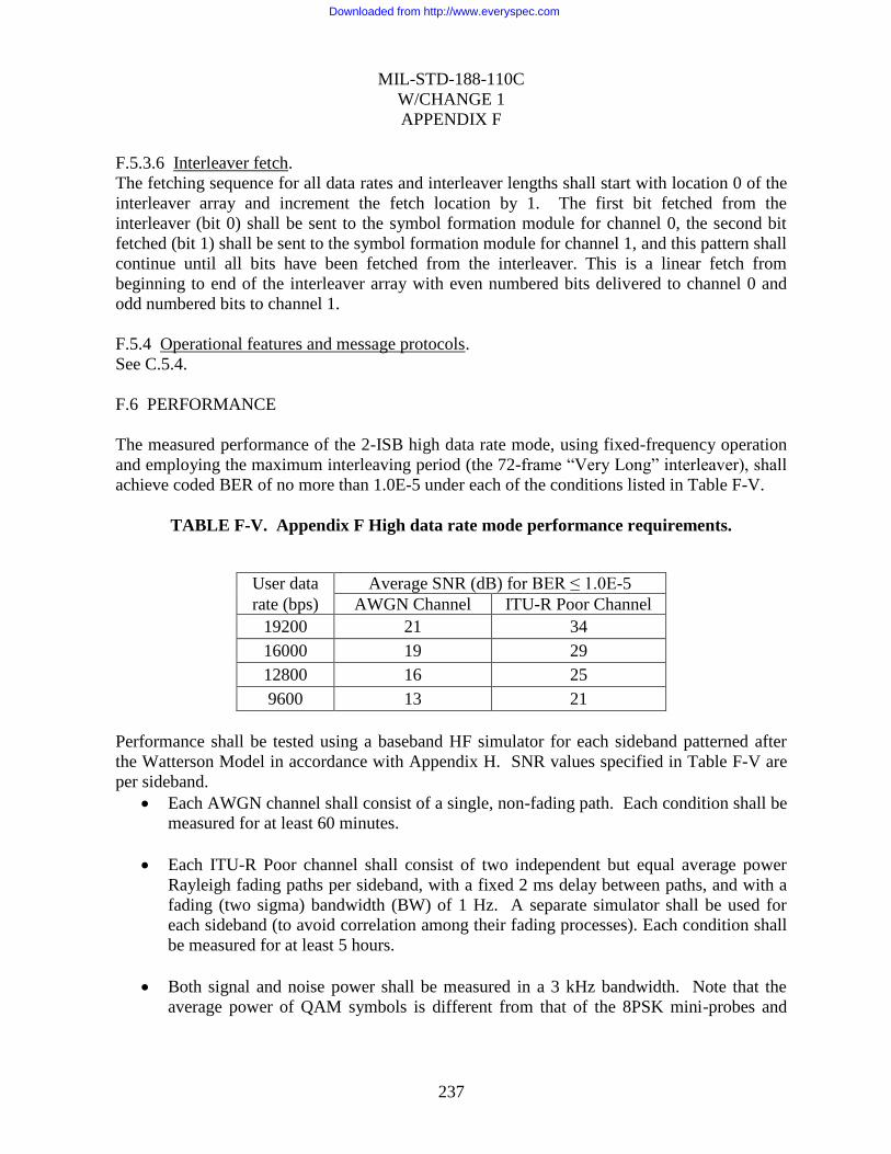
MIL-STD-188-110C
W/CHANGE 1
APPENDIX F
237
F.5.3.6 Interleaver fetch.
The fetching sequence for all data rates and interleaver lengths shall start with location 0 of the
interleaver array and increment the fetch location by 1. The first bit fetched from the
interleaver (bit 0) shall be sent to the symbol formation module for channel 0, the second bit
fetched (bit 1) shall be sent to the symbol formation module for channel 1, and this pattern shall
continue until all bits have been fetched from the interleaver. This is a linear fetch from
beginning to end of the interleaver array with even numbered bits delivered to channel 0 and
odd numbered bits to channel 1.
F.5.4 Operational features and message protocols.
See C.5.4.
F.6 PERFORMANCE
The measured performance of the 2-ISB high data rate mode, using fixed-frequency operation
and employing the maximum interleaving period (the 72-frame “Very Long” interleaver), shall
achieve coded BER of no more than 1.0E-5 under each of the conditions listed in Table F-V.
TABLE F-V. Appendix F High data rate mode performance requirements.
User data Average SNR (dB) for BER ≤ 1.0E-5
rate (bps) AWGN Channel ITU-R Poor Channel
19200 21 34
16000 19 29
12800 16 25
9600 13 21
Performance shall be tested using a baseband HF simulator for each sideband patterned after
the Watterson Model in accordance with Appendix H. SNR values specified in Table F-V are
per sideband.
Each AWGN channel shall consist of a single, non-fading path. Each condition shall be
measured for at least 60 minutes.
Each ITU-R Poor channel shall consist of two independent but equal average power
Rayleigh fading paths per sideband, with a fixed 2 ms delay between paths, and with a
fading (two sigma) bandwidth (BW) of 1 Hz. A separate simulator shall be used for
each sideband (to avoid correlation among their fading processes). Each condition shall
be measured for at least 5 hours.
Both signal and noise power shall be measured in a 3 kHz bandwidth. Note that the
average power of QAM symbols is different from that of the 8PSK mini-probes and
Downloaded from http://www.everyspec.com

MIL-STD-188-110C
W/CHANGE 1
APPENDIX F
238
reinserted preambles; the measured signal power shall be the long-term average of user
data, mini-probe, and reinserted preamble symbols.
When testing a modem embedded with a radio, so that only radio frequency (RF) signals are
available for testing, the RF signals must be down-converted to baseband for processing by the
channel simulator, and the result up-converted to RF for the receiver. In this case, the built-in
radio filters will affect the performance of the modems. Therefore, when testing embedded
modems, the SNR values specified in Table F-xyz shall be increased by 3 dB for all data rates.
F.7 ASSOCIATED COMMUNICATIONS EQUIPMENT
See C.7 “ASSOCIATED COMMUNICATIONS EQUIPMENT”
Downloaded from http://www.everyspec.com

MIL-STD-188-110C
W/CHANGE 1
239
CONCLUDING MATERIAL
Custodians: Preparing Activity:
Air Force – 71 Air Force – 71
Army – CR (Project Number TCSS-2012-001)
Navy – EC
Review Activities:
Air Force – 02, 07
Navy – MC
DoD – DC1, NS
NOTE: The activities listed above were interested in this document as of the date of this document.
Since organizations and responsibilities can change, you should verify the currency of the
information above using the ASSIST Online database at https://assist.daps.dla.mil.
Downloaded from http://www.everyspec.com