Embed Size (px)
Citation preview

NOT MEASUREMENT SENSITIVE
MIL-STD-2500C 01 May 2006 SUPERSEDING on 01 October 2006 MIL-STD-2500B/CN2 01 March 2001
DEPARTMENT OF DEFENSE
INTERFACE STANDARD
NATIONAL IMAGERY TRANSMISSION FORMAT VERSION 2.1
FOR THE NATIONAL IMAGERY TRANSMISSION FORMAT STANDARD
AMSC N/A AREA GINT

MIL-STD-2500C
ii
FOREWORD 1. This standard is approved for use by all departments and agencies of the Department of Defense (DOD). 2. The National Imagery Transmission Format Standard (NITFS) is the suite of standards for formatting digital imagery and imagery-related products and exchanging them among members of the Intelligence Community (IC) as defined by the Executive Order 12333, and other United States Government departments and agencies. 3. The NITFS Technical Board (NTB) developed this standard based upon currently available technical information. 4. The DOD and other IC members are committed to the interoperability of systems used for formatting, transmitting, receiving, and processing imagery and imagery-related information. This standard describes the National Imagery Transmission Format (NITF) file format and establishes its application within the NITFS. 5. Comments, suggestions or questions should be addressed to the National Geospatial-Intelligence Agency (NGA) National Center for Geospatial Intelligence Standards (NCGIS), Mail Stop P-106, 12310 Sunrise Valley Drive, Reston, VA 20191-3449, or emailed to [email protected]. Since contact information can change, you may want to verify the currency of this address information using the ASSIST Online database at http://assist.daps.dla.mil.

MIL-STD-2500C
iii
CONTENTS PARAGRAPH PAGE FOREWORD ...........................................................................................................................................ii
1. SCOPE .....................................................................................................................................................1 1.1 Scope..........................................................................................................................................1 1.2 Purpose ......................................................................................................................................1 1.3 Applicability ..............................................................................................................................1
2. APPLICABLE DOCUMENTS................................................................................................................1 2.1 General.......................................................................................................................................1 2.2 Government documents .............................................................................................................1 2.2.1 Specifications, standards, and handbooks..................................................................................1 2.2.2 Other Government documents, drawings, and publications.......................................................2 2.3 Non-Government publications...................................................................................................3 2.4 Order of precedence...................................................................................................................4
3. DEFINITIONS.........................................................................................................................................4 3.1 Acronyms used in this standard .................................................................................................4 3.2 Terms and definitions ..............................................................................................................13 3.2.1 Associated Data .......................................................................................................................13 3.2.2 Attachment Level (ALVL) ......................................................................................................13 3.2.3 Band.........................................................................................................................................13 3.2.4 Bandwidth................................................................................................................................13 3.2.5 Base Image...............................................................................................................................13 3.2.6 Basic Character Set (BCS).......................................................................................................13 3.2.7 Basic Character Set-Alphanumeric (BCS-A)...........................................................................13 3.2.8 Basic Character Set-Numeric Integer (BCS-N integer) ...........................................................13 3.2.9 Basic Character Set-Numeric Positive Integer (BCS-N positive integer)................................13 3.2.10 BCS Space ...............................................................................................................................14 3.2.11 Block........................................................................................................................................14 3.2.12 Blocked Image .........................................................................................................................14 3.2.13 Blocked Image Mask ...............................................................................................................14 3.2.14 Brightness ................................................................................................................................14 3.2.15 Byte..........................................................................................................................................14 3.2.16 Character..................................................................................................................................14 3.2.17 Common Coordinate System (CCS) ........................................................................................14 3.2.19 Conditional (C) ........................................................................................................................14 3.2.20 Controlled Extension (CE).......................................................................................................14 3.2.21 Coordinated Universal Time (UTC) ........................................................................................14 3.2.22 Data..........................................................................................................................................14 3.2.23 Data Communication ...............................................................................................................14 3.2.24 Data Extension Segment (DES)...............................................................................................14 3.2.25 Date Time Group (DTG) .........................................................................................................14 3.2.26 Digraph ....................................................................................................................................15 3.2.27 Extended Characer Set (ECS) ..................................................................................................15 3.2.28 Extended Characer Set (ECS) Space .......................................................................................15 3.2.29 Extended Characer Set - Alphanumeric (ECS-A)....................................................................15 3.2.30 Field .........................................................................................................................................15 3.2.31 Fill Pixel...................................................................................................................................15 3.2.32 Graphic ....................................................................................................................................15 3.2.33 Grey scale ................................................................................................................................15 3.2.34 Image .......................................................................................................................................15

MIL-STD-2500C
iv
3.2.35 Image Codes.............................................................................................................................15 3.2.36 Imagery ....................................................................................................................................15 3.2.37 Imagery Associated Data .........................................................................................................15 3.2.38 Interface ...................................................................................................................................15 3.2.39 Interoperability.........................................................................................................................16 3.2.409 Kernel.......................................................................................................................................16 3.2.41 Look-Up Table (LUT) .............................................................................................................16 3.2.42 Magnification...........................................................................................................................16 3.2.43 Military Grid Referencing System (MGRS) ............................................................................16 3.2.44 Network ...................................................................................................................................16 3.2.45 Non-blank ................................................................................................................................16 3.2.46 Null ..........................................................................................................................................16 3.2.47 0x_ ...........................................................................................................................................16 3.2.48 Pack Capable System...............................................................................................................16 3.2.49 Pad Pixel ..................................................................................................................................16 3.2.50 Pad Pixel Mask ........................................................................................................................16 3.2.51 Parity ........................................................................................................................................16 3.2.52 Pixel .........................................................................................................................................16 3.2.53 Primary Imagery ......................................................................................................................17 3.2.54 Processed Imagery ...................................................................................................................17 3.2.55 Protocol ....................................................................................................................................17 3.2.56 Pseudocolor..............................................................................................................................17 3.2.57 Reconstruction .........................................................................................................................17 3.2.58 Registered Extension (RE).......................................................................................................17 3.2.59 Reserved Extension Segment (RES) ........................................................................................17 3.2.60 Required...................................................................................................................................17 3.2.61 Resolution ................................................................................................................................17 3.2.62 Sample .....................................................................................................................................17 3.2.63 Secondary Imagery ..................................................................................................................17 3.2.64 Secondary Imagery Dissemination (SID) ................................................................................17 3.2.65 Secondary Imagery Dissemination System (SIDS)..................................................................17 3.2.66 Segment ...................................................................................................................................17 3.2.67 Tagged Record Extension (TRE) .............................................................................................17 3.2.68 Text ..........................................................................................................................................18 3.2.69 Tile ...........................................................................................................................................18 3.2.70 Universal Multiple Octet Coded Character Set (UCS).............................................................18 3.2.71 Universal Multiple Octet Coded Character Set (UCS) Transformation Format 8 (UTF-8) .....18 3.2.72 Universal Multiple Octet Coded Character Set (UCS) Transformation Format 8 (UTF-8)
Subset (U8S) ............................................................................................................................18 3.2.73 Universal Polar Stereographic (UPS).......................................................................................18 3.2.74 Universal Transverse Mercator (UTM)....................................................................................18 3.2.75 Unpack Capable System ..........................................................................................................18 3.2.76 Vector Quantization .................................................................................................................18 3.2.77 vsize .........................................................................................................................................18 3.2.78 v x h kernel...............................................................................................................................18
4. GENERAL REQUIREMENTS..............................................................................................................18 4.1 Background...............................................................................................................................18 4.2 NITF operations concept..........................................................................................................19 4.3 NITF design objectives ............................................................................................................20 4.4 NITF general requirements ......................................................................................................20 4.5 NITF characteristics.................................................................................................................20 4.6 NITF file structure ...................................................................................................................21 4.7 Common coordinate system (CCS)..........................................................................................21

MIL-STD-2500C
v
4.7.1 CCS structure...........................................................................................................................21 4.7.2 Row and column coordinates...................................................................................................21 4.7.3 Complexity Level (CLEVEL) constraints ...............................................................................22
5. DETAILED REQUIREMENTS ............................................................................................................22 5.1 Format description ...................................................................................................................22 5.1.1 Header, segments, and fields....................................................................................................22 5.1.2 Extension segments, conditional fields ....................................................................................22 5.1.3 Supported data types ................................................................................................................22 5.1.3.1 Image Segments (IS)................................................................................................................22 5.1.3.2 Graphic Segments (GS) ...........................................................................................................22 5.1.3..3 Reserved Segments (RS)..........................................................................................................22 5.1.3.4 Text Segment (TS)...................................................................................................................22 5.1.3.5 Data Extension Segment (TS)..................................................................................................22 5.1.3.6 Reserved Extension Segments (RES) ......................................................................................23 5.1.4 Application guidance ...............................................................................................................23 5.1.5 Standard data segment subheaders...........................................................................................23 5.1.6 Header/subheader field specification .......................................................................................23 5.1.7 Field structure and default values ............................................................................................23 5.1.8 Field types................................................................................................................................25 5.1.9 Logical recording formats........................................................................................................25 5.1.9.1 Bit and byte order ....................................................................................................................25 5.1.9.2 Row column relationship..........................................................................................................25 5.2 The NITF file header ...............................................................................................................25 5.2.1 Incomplete NITF file header....................................................................................................26 5.3 NITF product and overlay concept ..........................................................................................26 5.3.1 Image overlay relationships .....................................................................................................26 5.3.2 Overlays and Display Level (DLVL).......................................................................................27 5.3.3 Display Level (DLVL) interpretation ......................................................................................27 5.3.4 Attachment Level (ALVL) ......................................................................................................27 5.4 Image data................................................................................................................................28 5.4.1 General.....................................................................................................................................28 5.4.1.1 Image Representation (IREP) ..................................................................................................28 5.4.1.2 Image Category (ICAT)...........................................................................................................31 5.4.2 Image model ............................................................................................................................31 5.4.2.1 Display of NITF images...........................................................................................................31 5.4.2.2 Blocked images........................................................................................................................32 5.4.2.3 Blocked image masking ...........................................................................................................34 5.4.2.4 Pad pixel masking....................................................................................................................34 5.4.3 NITF image information ..........................................................................................................35 5.4.3.1 Image subheader ......................................................................................................................35 5.4.3.2 Image data mask ......................................................................................................................35 5.4.3.3 Image data format ....................................................................................................................35 5.4.3.3.1 Uncompressed image data format ............................................................................................35 5.4.3.3.1.1 Single band image uncompressed data format.........................................................................36 5.4.3.3.1.2 Multiple band image uncompressed data format .....................................................................36 5.4.3.3.1.2.1 Band sequential........................................................................................................................36 5.4.3.3.1.2.2. Band interleaved by pixel ........................................................................................................36 5.4.3.3.1.2.3 Band interleaved by block .......................................................................................................36 5.4.3.3.1.2.4 Band interleaved by row ..........................................................................................................36 5.4.3.3.2 Compressed image data format................................................................................................36 5.4.3.4 Grey scale look-up tables (LUT) ..............................................................................................36 5.4.3.5 Color look-up tables (LUT) .....................................................................................................37 5.5 Graphic data.............................................................................................................................37

MIL-STD-2500C
vi
5.5.1 Graphic subheader....................................................................................................................37 5.5.2 Graphic data format .................................................................................................................37 5.5.2.1 CGM graphic bounding box .....................................................................................................37 5.6 Reserved Segment (RS) ...........................................................................................................37 5.7 Text data ..................................................................................................................................37 5.7.1 Representation of textual information......................................................................................37 5.7.1.1 Standard (STA) ........................................................................................................................37 5.7.1.2 Message Text Formatting (MTF).............................................................................................38 5.7.1.3 ECS Text Formatting (UT1) ....................................................................................................38 5.7.1.4 U8S Text Formatting (U8S).....................................................................................................38 5.7.2 Text subheader .........................................................................................................................38 5.8 Data extensions ........................................................................................................................38 5.8.1 Tagged Record Extension (TRE) .............................................................................................38 5.8.1.1 Controlled Extension (CE).......................................................................................................39 5.8.1.2 Registered Extension (RE).......................................................................................................39 5.8.1.3 TRE placement.........................................................................................................................39 5.8.1.4 TRE registry.............................................................................................................................39 5.8.2 Data Extension Segment (DES) ...............................................................................................39 5.8.2.1 DES use....................................................................................................................................39 5.8.2.2 DES structure ...........................................................................................................................39 5.8.3 Defined DES ............................................................................................................................40 5.8.3.1 Tagged Record Extension Overflow (TRE-OVERFLOW) DES.............................................40 5.8.3.2 Streaming File Header (STREAMING-FILE-HEADER) DES ...............................................40 5.8.4 Reserved Extension Segment (RES).........................................................................................40 5.8.4.1 RES use....................................................................................................................................40 5.8.4.2 RES structure ...........................................................................................................................40 5.9 Complexity Level (CLEVEL)..................................................................................................41
6. NOTES...................................................................................................................................................41 6.1 Example NITF file ...................................................................................................................41 6.1.1 Use of NITF .............................................................................................................................41 6.1.2 Example file .............................................................................................................................41 6.1.2.1 Explanation of the file header ..................................................................................................44 6.1.2.2 Explanation of the image subheaders.......................................................................................45 6.1.2.2.1 Explanation of the first image subheader .................................................................................47 6.1.2.2.2 Explanation of the second image subheader ............................................................................49 6.1.2.3 Explanation of the graphic subheaders.....................................................................................49 6.1.2.3.1 Explanation of the first graphic subheader...............................................................................50 6.1.2.3.2 Explanation of the second graphic subheader ..........................................................................51 6.1.2.3.3 Explanation of the third graphic subheader..............................................................................52 6.1.2.3.4 Explanation of the fourth graphic subheader ...........................................................................53 6.1.2.3.5 Explanation of the fifth graphic subheader ..............................................................................55 6.1.2.4 Explanation of the text subheaders ..........................................................................................55 6.1.2.4.1 Explanation of the first text subheader.....................................................................................56 6.1.2.4.2 Sample USMTF message.........................................................................................................56 6.2 Product considerations .............................................................................................................57 6.2.1 NITF product configurations....................................................................................................57 6.2.1.1 General.....................................................................................................................................57 6.2.1.1.1 Single file, single base image...................................................................................................57 6.2.1.1.2 Single file, multiple images......................................................................................................57 6.2.1.1.3 Single file, no image ................................................................................................................57 6.2.1.1.4 Multiple correlated files ...........................................................................................................57 6.2.1.2 Single file, single base image...................................................................................................57 6.2.1.2.1 Image Segment (IS) overlays....................................................................................................58

MIL-STD-2500C
vii
6.2.1.2.2 Graphic Segment (GS) overlays ..............................................................................................58 6.2.1.2.3 Non-destructive overlays .........................................................................................................58 6.2.1.2.4 Text Segment (TS)...................................................................................................................59 6.2.1.2.5 Extension data..........................................................................................................................59 6.2.1.3 Single file, multiple images without overlap ...........................................................................59 6.2.1.3.1 Overlays...................................................................................................................................59 6.2.1.3.2 Text Segment (TS)...................................................................................................................60 6.2.1.3.3 Extension data..........................................................................................................................60 6.2.1.4 Single file, no image ................................................................................................................60 6.2.1.5 Multiple correlated files...........................................................................................................60 6.2.1.5.1 Stereo imagery .........................................................................................................................60 6.2.1.5.2 Imagery mosaics ......................................................................................................................60 6.2.1.5.3 Reduced resolution data sets (Rsets)........................................................................................60 6.2.1.5.4 Imagery and maps....................................................................................................................60 6.3 Sample NITF file structure ......................................................................................................62 6.4 Subject term (key word) listing................................................................................................62 6.5 Changes from previous issue ...................................................................................................63 6.5.1 Complexity Level 09................................................................................................................63 6.5.2 Large Block Option .................................................................................................................63 6.5.3 Spectral Data............................................................................................................................63 6.5.4 JPEG 2000 ...............................................................................................................................64 6.5.5 Number of allowed DES per file..............................................................................................64 6.5.6 Date and Time Fields ...............................................................................................................64 6.5.7 POLAR values .........................................................................................................................64 6.5.8 Bi-Level optional .....................................................................................................................64 6.5.9 Miscellaneous ..........................................................................................................................64 6.5.10 SI values for SAR/SARIQ .......................................................................................................65 6.5.11 Matrix Data (NODISPLY).......................................................................................................65 6.5.12 Header/subheader field specification .......................................................................................65 6.5.13 IGEOLO ..................................................................................................................................65 6.5.14 IMAG.......................................................................................................................................65 6.5.15 Fill/Pad Pixel............................................................................................................................65 FIGURE 1 NITF operational concept ........................................................................................................19 2 NITF functional architecture....................................................................................................20 3 NITF file structure ...................................................................................................................21 4 Common Coordinate System (CCS) example..........................................................................21 5 NITF file structure ...................................................................................................................23 6 Row column relationship .........................................................................................................25 7 NITF file header structure........................................................................................................26 8 NITF Display Level (DLVL) illustration.................................................................................29 9 Attachment Level (ALVL) relationships .................................................................................30 10 Image coordinate representation ..............................................................................................32 11 A blocked image ......................................................................................................................33 12 A blocked, filled image............................................................................................................33 13 A blocked, padded image with empty blocks ..........................................................................34 14 Tagged Record Extension (TRE).............................................................................................38 15 Sample file composite image ...................................................................................................41 16 Single file, single base image...................................................................................................58 17 Single file, multiple images .....................................................................................................61 B-1 A typical World Geodetic System 1984 (WGS 84) UTM zone (compressed) ......................147

MIL-STD-2500C
viii
TABLE I Example NITF file header........................................................................................................42 II Example of the first image subheader ......................................................................................45 III Example of the second image subheader .................................................................................47 IV Graphic subheader for the first graphic....................................................................................49 V Graphic subheader for the second graphic ...............................................................................50 VI Graphic subheader for the third graphic...................................................................................51 VII Graphic subheader for the fourth graphic ................................................................................52 VIII Graphic subheader for the fifthe graphic..................................................................................54 IX Text subheader for the text document ......................................................................................55 X Text subheader for USMTF .....................................................................................................56 XI Sample NITF file structure.......................................................................................................62 A-1 NITF file header.......................................................................................................................66 A-2 Display dependent parameters .................................................................................................74 A-2(A) Category dependent parameters ...............................................................................................75 A-2(B) Image Category (ICAT) value definitions ...............................................................................77 A-3 NITF image subheader.............................................................................................................78 A-3(A) NITF image data mask table ....................................................................................................98 A-4 Security control markings ......................................................................................................101 A-5 NITF graphic subheader.........................................................................................................102 A-6 NITF text subheader...............................................................................................................107 A-7 Registered and controlled tagged record extension format ....................................................112 A-8 NITF Data Extension Segment (DES) subheader ..................................................................112 A-8(A) Tagged Recod Extension Overflow (TRE-OVERFLOW) Data Extension Segment (DES)
subheader ...............................................................................................................................116 A-8(B) Streaming File Header (STREAMING_FILE_HEADER) Data Extension Segment (DES)
subheader ...............................................................................................................................120 A-9 NITF Reserved Extension Segment (RES) subheader ...........................................................124 A-10 NITF 02.10 complexity Level (CLEVEL).............................................................................128 B-1 NITF 1-Byte coded Characters ..............................................................................................136 B-2 NITF 2-Byte Coded Characters .............................................................................................144 APPENDIX A NITF TABLES.........................................................................................................................66 B IMPLEMENTATION CONSIDERATIONS ........................................................................132 C DATA EXTENSION .............................................................................................................148

MIL-STD-2500C
1
1. SCOPE
1.1 Scope. This standard establishes the requirements for the file format component of the NITFS. The file format described in this document is called the NITF. The NITFS is a collection of related standards and specifications developed to provide a foundation for interoperability in the dissemination of imagery and imagery associated data among different computer systems.
1.2 Purpose. This document, NITF 2.1, provides a detailed description of the standard file format structure. It specifies the valid data content and format for all fields defined within an NITF file. For this document, NITF refers to NITF Version 2.1. Several NITF implementation issues are addressed in the appendices. An example of NITF as the basis for file formation in tactical communications is provided in Section 6. Certifiable implementation of the NITF for support of interoperability is subject to constraints not specified in this standard. Pertinent compliance requirements are defined in CJCSI 6212.01D.
1.3 Applicability. This standard is applicable to DOD and other IC members. It is mandatory for all Secondary Imagery Dissemination Systems (SIDS) in accordance with the Assistant Secretary of Defense for Command, Control, Communications, and Intelligence (ASD (C3I)) memorandum, Subject: National Imagery Transmission Format Standard (NITFS), 12 August 1991, and is applicable also to all types of primary imagery systems such as Unmanned Aerial Vehicle (UAV), archives, and libraries. New equipment and systems, those undergoing major modification, or those capable of rehabilitation, will conform to this standard.
2. APPLICABLE DOCUMENTS
2.1 General. The documents listed in this section are specified in sections 3, 4, and 5 of this standard. This section does not include documents cited in other sections of this standard or recommended for additional information or as examples. While every effort has been made to ensure the completeness of this list, document users are cautioned that they must meet all specified requirements documents cited in sections 3, 4, and 5 of this standard, whether or not they are listed. At the time of publication, the editions indicated were valid. All documents are subject to revision and users of this standard should investigate recent editions and change notices of the documents listed below.
2.2 Government documents.
2.2.1 Specifications, standards, and handbooks. The following specifications, standards, and handbooks form a part of this document to the extent specified herein. Unless otherwise specified, the issue of these documents are those listed in the issue of the Department of Defense Index of Specifications and Standards (DODISS) and supplement thereto, cited in the solicitation.
FEDERAL INFORMATION PROCESSING STANDARDS
FIPS PUB 10-4 - Countries, Dependencies, Areas of Special Sovereignty, and Their Principal Administrative Divisions, April 1995
(Copies of Federal Information Processing Standards (FIPS) are available to DOD activities online at http://www.itl.nist.gov/fipspubs/index.htm or from the Standardization Document Order Desk, 700 Robbins Avenue, Building 4D, Philadelphia, PA 19111-5094. Others must request copies of FIPS from the National Technical Information Service, 5285 Port Royal Road, Springfield, VA 22161-2171.)

MIL-STD-2500C
2
STANDARDIZATION AGREEMENT
STANAG 7074 - Digital Geographic Information Exchange Standard (DIGEST) - AGeoP-3A, edition 1, 19 October 1994
(Copies of Standardization Agreements (STANAGs) can be obtained from the Central United States (US) Registry, 3072 Army Pentagon, Room 1B889, Washington, DC 20310-3072. Copies are available online at https://www.dgiwg.org/digest.)
DEPARTMENT OF DEFENSE STANDARDS
MIL-STD-188-198A - Joint Photographic Experts Group (JPEG) Image Compression for the National Imagery Transmission Format Standard, 15 December 1993 through NOTICE 3
MIL-STD-188-199 - Vector Quantization Decompression for the National Imagery Transmission Format Standard, 27 June 1994 through NOTICE 1
MIL-STD-2301A - Computer Graphics Metafile (CGM) for the National Imagery Transmission Format Standard, 5 June 1998
MIL-STD-6040 - United States Message Text Formatting (USMTF) Program, January 1997
(Unless otherwise indicated, copies of the above standards are available online at http://assist.daps.dla.mil/quicksearch/ or from the Standardization Document Order Desk, 700 Robbins Avenue, Building 4D, Philadelphia, PA 19111-5094.)
2.2.2 Other Government documents, drawings, and publications. The following other Government documents, drawings, and publications form a part of this document to the extent specified herein. Unless otherwise specified, the issues are those cited in the solicitation.
EXECUTIVE ORDER
EO 12958 - Classified National Security Information, 17 April 1995
DEPARTMENT OF DEFENSE REGULATION
DOD 5200.1-R - Department of Defense Information Security Program Regulation, 1996
CHAIRMAN JOINT CHIEF OF STAFF INSTRUCTION
CJCSI 6212.01D - Compatibility, Interoperability, and Integration of Command, Control, Communications, Computers, and Intelligence Systems, 8 March 2006
NATIONAL GEOSPATIAL-INTELLIGENCE AGENCY PUBLICATIONS
TR 8350.2 - Department of Defense World Geodetic System 1984, Third Edition, 4 July 1997 with Amendment 1 (3 January 2000) and Amendment 2 (23 June 2004)

MIL-STD-2500C
3
N-0105/98 - National Imagery Transmission Format Standard (NITFS) Standards Compliance and Interoperability Test and Evaluation Program Plan, 25 August 1998
N0106-97 - National Imagery Transmission Format Standard Bandwidth Compression Standards and Guidelines Document, 25 August 1998
(Copies of NGA documents can be obtained from the web at http://www.gwg.nga.mil/ntb/baseline/toc.html and http://earth-info.nga.mil/GandG/publications/index.html.)
2.3 Non-Government publications. The following documents form a part of this document to the extent specified herein. Unless otherwise specified, the issues of the documents which are DOD adopted are those listed in the issue of the DODISS cited in the solicitation. Unless otherwise specified, the issues or documents not listed in the DODISS are the issues or the documents cited in the solicitation.
INTERNATIONAL TELECOMMUNICATION UNION
ITU-R BT.601-5 - Studio encoding parameters of digital television for standard 4:3 and wide-screen 16:9 aspect ratios, 10/95
ITU-T T.4 - Standardization of group 3 facsimile apparatus for document transmission, AMD2 08/95
(Copies of these documents can be obtained online through http://www.itu.int.)
INTERNATIONAL ORGANIZATION FOR STANDARDIZATION
ISO 1000 - SI units and recommendations for the use of their multiples and of certain other units, 1992
ISO/IEC 7498-1 - Information technology - Open systems interconnection; Basic reference model - Part 1: The basic model, 1994
ISO/IEC 8632-1 - Information technology - Computer graphics - Metafile for the storage and transfer of picture description information: Functional specification, 1999
ISO 10646:2003 - Information technology - Universal multiple - octet coded character set (UCS)
ISO/IEC 10918-1 - Information technology - Digital compression and coding of continuous-tone still images - Part 1: Requirements and guidelines; 1994
ISO/IEC IS 12087-5 - Information technology - Computer graphics and image processing -Image processing and interchange (IPI) - Functional specification - Part 5: Basic image interchange format (BIIF), 1 December 1998
ISO/IEC 15444-1:2004
- Information technology - JPEG 2000 image coding system - Part 1: Core Coding System
ISO/IEC 15444-4:2004
- Information technology - JPEG 2000 image coding system - Part 4: Image Coding System: Conformance testing

MIL-STD-2500C
4
BPJ2K01.00 - Information technology - Computer graphics and image processing - registered graphical item - Class: BIIF Profile - BIIF Profile for JPEG 2000 Version 01.00 (BPJ2K01.00)
ISO/IEC BIIF PROFILE NSIF01.00
- Information Technology - Computer Graphics and Image Processing -Registered Graphical Item, Class: BIIF Profile - NATO Secondary Imagery Format Version 01.00 (NSIF01.00)
(Copies of these documents can be obtained online through http://www.ansi.org, http://www.iso.org, http://www.iec.ch, and http://www.itu.int. or from American National Standards Institute, 13th Floor, 11 West 42nd Street, New York, NY 10036.)
INSTITUTE OF ELECTRONIC AND ELECTRICAL ENGINEERS STANDARD
IEEE 754 - IEEE Standard for binary floating point arithmetic
(Copies of IEEE documents can be ordered online through http://ieee.org or from Customer Service, 445 Hose Lane, PO Box 1331, Piscataway, NJ 08855-1331.)
2.4 Order of precedence. In the event of a conflict between the text of this document and the references cited herein, the text of this document takes precedence. Nothing in this document, however, supersedes applicable laws and regulations unless a specific exemption has been obtained.
3. DEFINITIONS
3.1 Acronyms used in this standard. The acronyms used in this standard are defined as follows:
a ALVL - Attachment LeVeL
b. AMD - AMmenDment
c. AMSC - Acquisition Management Systems Control
d. ASCII - American Standard Code for Information Interchange
e. ASD (C3I) - Assistant Secretary of Defense for Command, Control, Communications, and Intelligence
f. B - band interleaved by Block (IMODE value)
g. BARO - Barometric pressure (ICAT value)
h. BCKGDA - BaCKGround Data
i. BCS - Basic Character Set
j. BCS-A - Basic Character Set Alphanumeric
k. BCS-N - Basic Character Set Numeric
l. BE - Basic Encyclopedia
m. BGHIGHT - BackGround HeIGHT
n. BGWIDTH - BackGround WIDTH

MIL-STD-2500C
5
o. BIIF - Basic Image Interchange Format (ISO/IEC IS 12087-5)
p. BMP - Basic Multilingual Plane
q. BMRnBNDm - nth Block Mask Record of BaND m
r. BP - Black/white frame Photography (ICAT value)
s C - (1) Column (2) Conditional
t. C1 - Bi-level (IC value)
u. C3 - JPEG (IC value)
v. C4 - Vector Quantization (IC value)
w. C5 - Lossless JPEG (IC value)
x. CAT - Computerized Axial Tomography scan (ICAT value)
y. CCS - Common Coordinate System
z. CE - Controlled Extension
aa. CEDATA - Controlled Extension user-defined DATA
ab. CETAG - Controlled unique Extension Type identifier
ac. CGM - Computer Graphics Metafile
ad. CJCSI - Chairman Joint Chief of Staff Instruction
ae. CLEVEL - Complexity LEVEL
af. CP - Color frame Photography (ICAT value)
ag. CRT - Cathode Ray Tube
ah. CURRENT - water Current (ICAT value)
ai. DC - District of Columbia
aj. DD - Defense Department
ak. DEPTH - water Depth (ICAT value)
al. DES - Data Extension Segment
am. DESDATA - DES user-defined DATA
an. DESITEM - DES data segment overflowed
ao. DESOFLW - DES OverFLoW header type
ap. DESSHF - DES user-defined SubHeader Field

MIL-STD-2500C
6
aq. DESSHL - DES user-defined SubHeader Length
ar. DIGEST - Digital Geographic Information Exchange Standard (http://www.digest.org)
as. DLVL - Display LeVeL
at. DOD - Department Of Defense
au. DODISS - Department Of Defense Index of Specifications and Standards
av. DTEM - Digital Terrain Elevation Model (ICAT value)
aw. EEI - Essential Elements of Information
ax. ENCRYP - File ENCRYPtion
ay. EO - (1) Executive Order (2) Electro-Optical (ICAT value)
az. ECS - Extended Character Set
ba. ECS-A - Extended Character Set-Alphanumeric
bb. FBKGC - File BacKGround Color
bc. FDT - File Date and Time
bd. FHDR - File profile name
be. FIPS - Federal Information Processing Standard
bf. FIPS PUB - FIPS Publication
bg. FL - (1) Forward Looking infrared (ICAT value) (2) File Length
bh. FORMETS - NATO Message Text Formatting System
bi. FOUO - For Official Use Only
bj. FP - Fingerprints (ICAT value)
bk. FSCATP - File Classification Authority TyPe
bl. FSCAUT - File Classification AUThority
bm. FSCLAS - File Security CLASsification
bn. FSCLSY - File Security Classification System
bo. FSCLTX - File CLassification TeXt
bp. FSCODE - File Security CODEwords
bq. FSCRSN - File Classification ReaSoN

MIL-STD-2500C
7
br. FSCTLH - File ConTroL and Handling
bs. FSCTLN - File Security ConTroL Number
bt. FSDCDT - File DeClassification DaTe
bu. FSDCTP - File DeClassification TyPe
bv. FSDCXM - File DeClassification eXeMption
bw. FSDG - File DownGrade
bx. FSDGDT - File DownGrade DaTe
by. FSREL - File REL instructions
bz. FSSRDT - File Security SouRce DaTe
ca. FTITLE - File TITLE
cb. FVER - File VERsion
cc. GS - Graphic Segment
cd. HL - file Header Length
ce. HR - High Resolution radar (ICAT value)
cf. HS - HyperSpectral (ICAT value)
cg. HTML - Hypertext Mark-up Language
ch. I - Inphase
ci. I1 - Downsampled JPEG (IC value)
cj. IC - (1) Intelligence Community (2) Image Compression
ck. ICAT - Image Category
cl. ICORDS - Image Coordinate Representation
cm. IDLVL - Image Display LeVeL
cn. IEC - International Electrotechnical Commission
co. IEEE - Institute of Electronic and Electrical Engineers
cp. IGEOLO - Image Coordinate Location
cq. ILOC - Image Location
cr. IMODE - Image Mode
cs. INST - INformation Standards and Technology

MIL-STD-2500C
8
ct. IPI - Image Processing and Interchange
cu. IR - InfRared (ICAT value)
cv. IREP - Image REPresentation
cw. IREPBANDn - IREP nth BAND representation
cx. IS - Image Segment
cy. ISO - International Organization for Standardization
cz. ISUBCATn - image nth band SUBCATegory
da. ITU - International Telecommunication Union
db. ITU-R - ITU Recommendation
dc. ITU-T - ITU Telecommunications
dd. IXSHD - Image eXtended SubHeader Data
de. JITC - Joint Interoperability Test Command
df. JPEG - Joint Photographic Experts Group
dg. LDn - Length of nth Data extension segment
dh. LEG - Legend (ICAT value)
di. LIn - Length of the nth Image segment
dj. LISHn - Length of the nth Image SubHeader
dk. LOC - Location
dl. LOCG - LOCation Grid (ICAT value)
dm. LSB - Least Significant Bit
dn. LSn - Length of the nth graphic segment
do. LSSHn - Length of the nth graphic SubHeader
dp. LUT - Look-Up Table
dq. M - Magnitude
dr. M1 - Compressed Bi-level (IC value)
ds. M3 - Compressed JPEG (IC value)
dt. M4 - Compressed Vector Quantization (IC value)
du. M5 - Compressed Lossless JPEG (IC value)
dv. MAP - raster MAP (ICAT value)

MIL-STD-2500C
9
dw. MATR - MATRix data (ICAT value)
dx. MGRS - Military Grid Reference System
dy. MIL-STD - MILitary STandarD
dz. MONO - MONOchrome (IREP value)
ea. MRI - Magnetic Resonance Imagery (ICAT value)
eb. MS - MultiSpectral (ICAT value)
ec. MSB - Most Significant Bit
ed. MTF - Message Text Formatting (TXTFMT value)
ee. MULTI - MULTIband Imagery (IREP value)
ef. N - UTM/UPS Northern Hemisphere (ICORDS field value)
eg. NATO - North Atlantic Treaty Organization
eh. NBPC - Number of Blocks Per Column
ei. NBPR - Number of Blocks Per Row
ej. NC - No Compression
ek. NELUTn - Number of LUT Entries for the nth image band
el. NGA - National Geospatial-Intelligence Agency (previously the National Imagery and Mapping Agency, NIMA)
em. NICOM - Number of Image COMments
en. NITF - National Imagery Transmission Format
eo. NITFS - National Imagery Transmission Format Standard
ep. NM - Uncompressed image indicating an image that contains a Block Mask or a Pad Pixel Mask (IC value)
eq. NODISPLY - No DISPLaY (IREP value)
er. NPPBH - Number of Pixels Per Block Horizontal
es. NPPBV - Number of Pixels Per Block Vertical
et. NSIF - NATO Secondary Imagery Format
eu. NSIL - NATO Standard Image Library
ev. NTB - NITFS Technical Board
ew. NUMDES - NUMber of Data Extension Segments
ex. NUMI - NUMber of Image segments

MIL-STD-2500C
10
ey. NUMRES - NUMber of Reserved Extension Segments
ez. NUMS - NUMber of graphic segments
fa. NUMT - NUMber of text segments
fb. NUMX - Reserved for Future Use
fc. NVECTOR - VECTOR with Cartesian coordinates (IREP value)
fd. NY - New York
fe. OADR - Originating Agency Determination Required
ff. ONAME - Originator’s NAME
fg. OP - Optical (ICAT value)
fh. OPHONE - Originator’s PHONE number
fi. P - (1) Phase (2) band interleaved by Pixel (IMODE value)
fj. PA - PennsylvaniA
fk. PAT - color PATch (ICAT value)
fl. PJUST - Pixel JUSTifcation
fm. PO - Post Office
fn. POLAR - Vector with POLAR coordinates (IREP value)
fo. PROPIN - Proprietary Information
fp. Q - Quadrature
fq. R - (1) Row (2) band interleaved by Row (IMODE value) (3) Required
fr. RD - RaDar (ICAT value)
fs. RE - Registered Extension
ft. REDATA - RES user-defined DATA
fu. RES - Reserved Extension Segment
fv. RESSHF - RES user-defined Subheader Fields
fw. RESSHL - RES user-defined SubHeader Length
fx. RETAG - Registered unique Extension Type identifier
fy. RGB - Red, Green, Blue (IREP value)

MIL-STD-2500C
11
fz. RGB/LUT - mapped color (IREP value)
ga. RS - Reserved Segment
gb. Rset - Reduced resolution data set
gc. RTF - Rich Text Format
gd. S - (1) band Sequential (IMODE field value) (2) UTM/UPS Southern Hemisphere (ICORDS field value) (3) Secret (security fields value)
ge. SAR - Synthetic Aperture Radar (ICAT value)
gf. SARIQ - SAR radio hologram (ICAT value)
gg. SBND1 - Graphic BouND 1
gh. SBND2 - Graphic BouND 2
gi. SDE - Support Data Extension
gj. SDIF - SGML Document Interchange Format
gk. SDLVL - Graphic Display LeVeL
gl. SFH - Streaming File Header
gm. SFH_DELIM1 - SFH Delimiter 1
gn. SFH_DELIM2 - SFH Delimiter 2
go. SFH_L1 - SFH Length 1
gp. SFH_L2 - SFH Length 2
gq. SGML - Standard Generalized Mark-up Language
gr. SI - International System of units (the modern metric system)
gs. SID - (1) Secondary Imagery Dissemination System (2) Graphic Identifier
gt. SIDS - Secondary Imagery Dissemination System
gu. SL - Side-Looking radar (ICAT value)
gv. SLOC - Graphic LOCation
gw. STA - Standard (TXTFMT value)
gx. STANAG - STANdardization AGreement
gy. STREAMING_FILE_HEADER - Streaming File Header (DESID value)

MIL-STD-2500C
12
gz. STYPE - Standard TYPE
ha. SXSHD - Graphic extended SubHeader Data
hb. TFS - Transportable File Structure
hc. TI - Thermal Infrared (ICAT value)
hd. TMRnBNDm - nth Pad Pixel Mask Record for BAND m
he. TPXCD - Pad Output Pixel Code
hf. TPXCDLNTH - Pad Output Pixel Code Length
hg. TRE - Tagged Record Extension
hh. TRE_OVERFLOW - TRE overflow (DESID value)
hi. TS - (1) Text Segment (2) Top Secret
hj. TXSHD - Text eXtended SubHeader Data
hk. TXTFMT - TeXT ForMaT
hl. U8S - UTF-8 Subset
hm. UAV - Unmanned Aerial Vehicle
hn. UCS - Universal multiple octet coded Character Set
ho. UDHD - User-Defined Header Data
hp. UDHDL - User-Defined Header Data Length
hq. UIP - USIGS Interoperability Profile
hr. URL - Universal Resource Locator
hs. US - United States
ht. USMTF - US Message Text Formatting
hu. UTC - Coordinated Universal Time
hv. UTF - UCS Transformation Format
hw. UTM/UPS - Universal Transverse Mercator/Universal Polar Stereographic
hx. VA - VirginiA
hy. VD - ViDeo (ICAT value)
hz. VDC - Virtual Display Coordinates
ia. VIS - VISible Imagery (ICAT value)

MIL-STD-2500C
13
ib. VPH - Video Phase History (IREP value)
ic. VQ - Vector Quantization
id. WGS - World Geodetic System
ie. WGS 84 - World Geodetic System 1984
if. WIND - air Wind charts (ICAT value)
ig. XHD - eXtended Header Data
ih. XHDL - eXtended Header Data Length
ii. XRAY - X-ray (ICAT value)
ij. YCbCr601 - Y, brightness; Cb, chrominance (blue); Cr, chrominance (red) (ITU-R BT.601-5) (IREP value)
ik. ZULU - Zero meridian
3.2 Terms and definitions. The following terms and definitions are used for the purpose of this standard. All used concepts (file, field, segment, etc.) exclusively refer to the NITF standard. For concepts for which this is not correct a corresponding firm intention has been chosen (for example: system field, BIIF file, etc.).
3.2.1 Associated Data. That related data required for completeness of the standard.
3.2.2 Attachment Level (ALVL). A way to associate images and graphics to the same level during movement, rotation, or display.
3.2.3 Band. A well defined range of wavelengths, frequencies or energies of optical, electric, or acoustic radiation. At the pixel level, a band is represented as one of the vector values of the pixel.
3.2.4 Bandwidth. 1. The difference between the limiting frequencies within which performance of a device, in respect to some characteristic, falls within specified limits. 2. The difference between the limiting frequencies of a continuous frequency band.
3.2.5 Base Image. A base image is the principle image of interest or focus for which other data may be inset or overlaid. The NITF file can have none, one, or multiple base images. For multiple base images in a single NITF file, the relative location of each base image is defined in the image location (ILOC) field in each image subheader. This location will be the offset within the Common Coordinate System (CCS).
3.2.6 Basic Character Set (BCS). A subset of the Extended Character Set (ECS). The most significant bit of the BCS characters is set to 0. The range of valid BCS characters code is limited to 0x20 to 0x7E plus line feed (0x0A), form feed (0x0C), and carriage return, (0x0D).
3.2.7 Basic Character Set-Alphanumeric (BCS-A). A subset of the Basic Character Set. The range of allowable characters consists of space to tilde, codes 0x20 to 0x7E.
3.2.8 Basic Character Set-Numeric Integer (BCS-N integer). A subset of the Basic Character Set-Numeric (BCS-N) comprising the digits 0 to 9 (codes 0x30 to 0x39), plus sign (code 0x2B) and minus sign (code 0x2D).
3.2.9 Basic Character Set – Numeric Positive Integer (BCS-N positive integer). A subset of the Basic Character Set Numeric (BCS-N) comprising the digits 0 to 9 (codes 0x30 to 0x39).

MIL-STD-2500C
14
3.2.10 BCS Space. BCS (and consequently ECS) code 0x20.
3.2.11 Block. A block is a rectangular array of pixels. (Synonymous with tile.)
3.2.12 Blocked Image. A blocked image is composed of the union of one or more non-overlapping blocks. (Synonymous with tiled image.)
3.2.13 Blocked Image Mask. A structure which identifies the blocks in a blocked (tiled) image which contain no valid data, and which are not included in the file. The structure allows the receiver to recognize the offset for each recorded/transmitted block. For example, a 2x2 blocked image file which contains no valid data in the second block (block 1) would be recorded in the order: block 0, block 2, block 3. The blocked image mask would identify block 1 as a non-existing block, and would allow the receiving application to construct the image in the correct order.
3.2.14 Brightness. An attribute of visual perception, in accordance with which a source appears to emit more or less light. A pixel with a higher value is brighter than a pixel with a lower value.
3.2.15 Byte. A sequence of 8 adjacent binary digits.
3.2.16 Character. 1. A letter, digit, or other graphic that is used as part of the organization, control, or representation of data. 2. One of the units of an alphabet.
3.2.17 Common Coordinate System (CCS). The virtual two dimensional Cartesian-like coordinate space which will be common for determining the placement and orientation of displayable data.
3.2.18 Complexity Level (CLEVEL). A code used in the file header which signals the degree of complexity an interpret implementation needs to support to adequately interpret the files. Items that differentiate complexity include: size of the common coordinate system, file size, image size, image blocking, color of imagery with greater than 8-bit per pixel, number of bands in an image segment, number of image segments, aggregate size of graphic segments, etc.
3.2.19 Conditional (C). A state applied to an NITF header or subheader data field whose existence and content is dependent on the existence and/or content of another field.
3.2.20 Controlled Extension (CE). Those tagged record extensions which are submitted for approval by the NTB and are then maintained under formal configuration management control. Both the extension type identifier (six character CETAG field) and the user-defined data (CEDATA field) structure is under configuration management control.
3.2.21 Coordinated Universal Time (UTC). The time scale maintained by the International Earth Rotation Service (having previously been maintained by the Bureau International de l’Heure that forms the basis of a coordinated dissemination of standard frequencies and time signals.
3.2.22 Data. Information in digital format.
3.2.23 Data Communication. The transfer of information between functional units by means of data transmission according to a protocol.
3.3.24 Data Extension Segment (DES). A type of extension segment with sub-header and data fields structured similarly to the standard data types in the NITF (e.g., image, label, symbol, text). The extension type identifier (25 character DESTAG field), the version (two character DESVER field), and the full underlying structure is under configuration management control as registered with the NTB.
3.2.25 Date Time Group (DTG). A composite representation of date and time.

MIL-STD-2500C
15
3.2.26 Digraph. A two letter reference code.
3.2.27 Extended Character Set (ECS). A set of 1-byte encoded characters. Valid ECS character codes range from 0x20 to 0x7E, and 0xA0 to 0xFF, as well as Line Feed (0x0A), Form Feed (0x0C) and Carriage Return (0x0D). The ECS characters are described in Table B-1. As an interim measure, because of inconsistencies between standards, it is strongly advised that character codes ranging from 0xA0 to 0xFF should never be used. Therefore, the use of ECS characters should be restricted to its BCS Subset.
3.2.28 Extended Character Set (ECS) Space. See BCS Space definition.
3.2.29 Extended Character Set - Alphanumeric (ECS-A). A subset of the Extended Character Set (ECS). Valid ECS-A character codes range from 0x20 to 0x7E, and 0xA0 to 0xFF. Line Feed (0x0A), Form Feed (0x0C) and Carriage Return (0x0D) are not valid ECS-A characters. As an interim measure, because of inconsistencies between standards, it is strongly advised that character codes ranging from 0xA0 to 0xFF should never be used. Therefore, the use of ECS-A characters should be restricted to its BCS-A Subset.
3.2.30 Field. Elementary set of meaningful data.
3.2.31 Fill Pixel: A pixel that has relevance to the storage and transmission of a blocked image, but no relevance to the display of the blocked image. Fill pixels are used when NROWS (the number of pixel rows in an image) is not an integer multiple of the number of pixel rows per image block, or when NCOLS (the number of pixel columns in an image) is not an integer multiple of the number of pixel columns per block. Fill pixels are always outside the boundary specified by NROWS and NCOLS, and therefore are never displayed.
3.2.32 Graphic. Graphic data is used in the NITF to store two-dimensional information represented as a Computer Graphics Metafile (CGM). Each graphic segment consists of a symbol subheader and data. A graphic may be black and white, grey scale, or color. Examples of graphics are circles, ellipses, rectangles, arrows, lines, triangles, logos, unit designators, object designators (ships, aircraft), text, special characters, or combination thereof. A graphic is stored as a distinct unit in the NITF file allowing it to be manipulated and displayed nondestructively relative to the images, and other graphics in the file. This standard does not preclude the use of n-dimensional graphics when future standards are developed.
3.2.33 Grey scale. An optical pattern consisting of discrete steps or shades of grey between black and white.
3.2.34 Image. A two-dimensional rectangular array of pixels indexed by row and column.
3.2.35 Image Codes. For a vector quantized image file, values in the image data section that are used to retrieve the v x h kernels from the image code book.
3.2.36 Imagery. Collectively, the representations of objects reproduced electronically or by optical means on film, electronic display devices, or other media.
3.2.37 Imagery Associated Data. Data which is needed to properly interpret and render pixels; data which is used to annotate imagery such as text, graphics, etc.; data which describes the imagery such as textual reports; and data which support the exploitation of imagery.
3.2.38 Interface. 1. A concept involving the definition of the interconnection between two equipment items or systems. The definition includes the type, quantity, and function of the interconnecting circuits and the type, form, and content of signals to be interchanged via those circuits. Mechanical details of plugs, sockets, and pin numbers, etc., can be included within the context of the definition. 2. A shared boundary, e.g., the boundary between two subsystems or two devices. 3. A boundary or point common to two or more similar or dissimilar command and control systems, subsystems, or other entities against which or at which necessary information flow takes place. 4. A boundary or point common to two or more systems or other entities across which useful information flow takes place. (It is implied that useful information flow requires the definition of the

MIL-STD-2500C
16
interconnection of the systems which enables them to interoperate.) 5. The process of interrelating two or more dissimilar circuits or systems 6. The point of interconnection between user terminal equipment and commercial communication-service facilities.
3.2.39 Interoperability. The ability of systems, units, or forces to provide services to and accept services from other systems, units, or forces and to use the services so exchanged to enable them to operate effectively together.
3.2.40 Kernel. For a vector quantized image file, a rectangular group of pixels used in the organization of quantizing image data.
3.2.41 Look-Up Table (LUT). A collection of values used for translating image samples from one value to another. The current sample value is used as an index into the look-up table(s); therefore, the number of entries in each look-up table for a binary image would contain two entries, and each look-up table for an 8-bit image would contain 256 entries. Multiple look-up tables allow for the translation of a 1-vector pixel value to an n-vector pixel value.
3.2.42 Magnification. The multiplication factor which causes an apparent change in linear distance between two points in an image. Thus a magnification of 2 is a change which doubles the apparent distance between two points (multiplying area by 4), while a magnification of 0.5 is a change which halves the apparent distance.
3.2.43 Military Grid Referencing System (MGRS). A means of expressing Universal Transverse Mercator (UTM) or Universal Polar Stereographic (UPS) coordinates as a character string, with the 100-kilometer components replaced by special letters (which depend on the UTM or UPS zone and ellipsoid).
3.2.44 Network. 1. An interconnection of three or more communicating entities and (usually) one or more nodes. 2. A combination of passive or active electronic components that serves a given purpose.
3.2.45 Non-blank. Non-blank indicates that the field cannot be filled by the character space (0x20) but may contain the character space when included with other characters. (embedded blanks)
3.2.46 Null. The field is filled entirely with spaces (0x20).
3.2.47 0x_. Hexadecimal notation.
3.2.48 Pack Capable System. A system which is capable of generating an NITF file.
3.2.49 Pad Pixel. A non-intelligent pixel that is within the significant image pixels defined by NROWS and NCOLS. The numerical value of the pad pixel is specified by the NITF Image Data Mask Table, Pad Output Pixel Code (TPXCD) field, which can only be present when the compression code (IC) includes the letter “M.” Pad pixels can be located anywhere inside the significant image pixels defined by NROWS and NCOLS, and therefore impact the display of the image.
3.2.50 Pad Pixel Mask. A data structure which identifies recorded/transmitted image blocks which contain pad pixels. The pad pixel mask allows applications to identify image blocks which require special interpretation due to pad pixel content.
3.2.51 Parity. In binary-coded systems, the oddness or evenness of the number of ones in a finite binary stream. It is often used as a simple error-detection check and will detect (but not correct) the occurrences of any single bit error in the field.
3.2.52 Pixel. A pixel is represented by an n-vector of sample values, where n corresponds to the number of bands comprising the image.

MIL-STD-2500C
17
3.2.53 Primary Imagery. Unexploited, original imagery data that has been derived directly from a sensor. Elementary processing may have been applied at the sensor, and the data stream may include auxiliary data.
3.2.54 Processed Imagery. Imagery that has been formatted into image pixel format, enhanced to remove detected anomalies, and converted to a format appropriate for subsequent disposition.
3.2.55 Protocol. 1. [In general], A set of semantic and syntactic rules that determines the behavior of functional units in achieving communication. For example, a data link protocol is the specification of methods whereby data communication over a data link is performed in terms of the particular transmission mode, control procedures, and recovery procedures. 2. In layered communication system architecture, a formal set of procedures that are adopted to facilitate functional interoperation within the layered hierarchy. Note: Protocols may govern portions of a network, types of service, or administrative procedures.
3.2.56 Pseudocolor. A user-defined mapping of N bits into arbitrary colors.
3.2.57 Reconstruction. For a vector quantized image file, the process of transforming an image from a quantized form into a displayable and exploitable form.
3.2.58 Registered Extension (RE). Those tagged record extensions for which the extension type identifier (six character RETAG field) and the user-defined data (REDATA field) structure is registered with the NTB. The user-defined data (REDATA field) structure is not controlled by the NTB.
3.2.59 Reserved Extension Segment (RES). A type of extension segment with sub-header and data fields structured similarly to the standard data types in the NITF (e.g., image, label, symbol, text). The extension type identifier (25 character RESTAG field), the version (two character RESVER field), and the full underlying structure is under configuration management control as registered with the NTB. The RES construct provides the same mechanism as the DES construct for adding a variety of new data types for inclusion in NITF files. However, the RES is reserved for data types that need to be placed at or near the end of the file. For example, a digital signature that covered the whole file could be defined for placement in a RES to verify the bit level integrity of the NITF file.
3.2.60 Required. An NITF header or subheader field that must be present and filled with valid data.
3.2.61 Resolution. 1. The minimum difference between two discrete values that can be distinguished by a measuring device. 2. The degree of precision to which a quantity can be measured or determined. 3. A measurement of the smallest detail that can be distinguished by a sensor system under specific conditions. Note: High resolution does not necessarily imply high accuracy.
3.2.62 Sample. The atomic element of an image pixel having a discrete value. One sample from the same location in each band comprising an image will combine to form a pixel.
3.2.63 Secondary Imagery. Secondary Imagery is digital imagery and/or digital imagery products derived from primary imagery or from the further processing of secondary imagery.
3.2.64 Secondary Imagery Dissemination (SID). The process of dispersing or distributing digital secondary imagery.
3.2.65 Secondary Imagery Dissemination System (SIDS). The equipment and procedures used in secondary imagery dissemination.
3.2.66 Segment. A header and data fields.
3.2.67 Tagged Record Extension (TRE). A set of fields to support user defined and extended data.

MIL-STD-2500C
18
3.2.68 Text. Information conveyed as characters.
3.2.69 Tile. Synonymous with Block
3.2.70 Universal Multiple Octet Coded Character Set (UCS). The Universal Multiple Octet Coded Character Set is used for expressing text that must be human readable, potentially in any language of the world. It is defined in ISO/IEC 10646.
3.2.71 Universal Multiple Octet Coded Character Set (UCS) Transformation Format 8 (UTF-8). UTF-8 is a coded representation form for all of the characters of the UCS. In the UTF-8 coded representation form each character from this UCS has a coded representation that comprises a sequence of octets of length 1, 2, 3, 4, 5, or 6 octets.
3.2.72 Universal Multiple Octet Coded Character Set (UCS) Transformation Format 8 (UTF-8) Subset (U8S). A Subset of the UCS composed of 1-byte and 2-byte UTF-8 encoded characters (Basic Latin and Latin Supplement 1). The 1-byte encoded characters of the UTF-8 Subset (U8S) are the BCS characters. The 2-byte encoded characters of U8S are described in Table B-2.
3.2.73 Universal Polar Stereographic (UPS). A pair of grids, one used north of 84o north and one used south of 80o south. Each grid is based on the polar stereographic projection. The actual grid depends on the choice of the geodetic datum.
3.2.74 Universal Transverse Mercator (UTM). A system of grids for global use between latitudes 84 degrees North and 80 degrees South. The range of longitudes 180 degrees West to 180 degrees East is divided into 60 zones, each of which is a grid based on the Transverse Mercator projection. (Within each zone, there is a difference in coordinate systems either side of the Equator. On the northern side, northings start from zero at the Equator; on the southern side, northings are positive rising to 10 million at the Equator.) The actual grid depends on the choice of geodetic datum as well as the zone.
3.2.75 Unpack Capable System. A system which is capable of receiving/processing an NITF file.
3.2.76 Vector Quantization (VQ). A compression technique in which many groups of pixels in an image are replaced by a smaller number of image codes. A clustering technique is used to develop a code book of "best fit" pixel groups to be represented by the codes. Compression is achieved because the image codes can be recorded using fewer bits than the original groups of pixels they represent.
3.2.77 vsize. For a vector quantized image file, the size of the kernel in pixels.
3.2.78 v x h kernel. For a vector quantized image file, a rectangular group of pixels (kernels) with v-rows and h-columns.
4. GENERAL REQUIREMENTS
4.1 Background. The DOD and the IC use many types of systems for the reception, transmission, storage, and processing of images, graphics, text, and other associated data. Without special efforts, the file format used in systems of one service or agency are likely to be incompatible with the format of another system. Since each system may use a unique, internal data representation, a common format for exchange of information across systems is needed for interoperability of systems within and among DOD and IC organizations. As the need for imagery-related systems grows, their diversity is anticipated to increase. The need to exchange data is also anticipated to increase, even though systems of each organization must retain their own individual characteristics and capabilities. This document defines the NITF, the standard file format for imagery and imagery-related products to be used by the DOD and IC. The NITF provides a common basis for storage and interchange of images and associated data among existing and future systems. The NITF can be used to support interoperability by providing a data format for shared access applications, while also serving as a standard file format for dissemination of images, graphics, text, and associated data.

MIL-STD-2500C
19
4.2 NITF operations concept. The NITF shall be used as an interoperability format for transmission and storage of electronic imagery within and among DOD and IC organizations. The NITF has direct application to the dissemination of imagery to requesters of imagery derived intelligence. Multimedia intelligence reports will be composed and packaged into a single file which answers the Essential Elements of Information (EEI) of a particular requester. Intelligence reports may be composed of textual reports along with images, annotated images, graphics, and maps. Intelligence reports are generated after an interpreter exploits primary images or further exploits secondary images pulled out of an archive. The NITF is suitable for archiving imagery required to support the collection process in the reconnaissance cycle. Figure 1 illustrates the elements used in the exploitation process of the reconnaissance cycle.
ImageExploitation
Primary ImageryIntelligence RequestSecondary Imagery
CollateralInformation
SecondaryImagery
FIGURE 1. NITF operational concept.
In the NITF concept, imagery data interchange between systems is organized in files and is enabled by a potential cross-translation process. When systems use other than NITF as an internal imagery format, each system will have to translate between the system's internal representation for files, and the NITF file format. A system from which imagery data is to be transferred is envisioned to have a translation module that accepts information, structured according to the system's internal representation for images, graphics, text, and other associated data, and assembles this information into one file in the standard NITF file format. Then the file will be exchanged with one or more recipients. The receiving systems will reformat the file, converting it into one or more files structured as required by the internal representation of the receiving station. The functional architecture of this cross-translation process is shown on figure 2. In the diagram, the terms "Native1 File Format" and "Native2 File Format" refer to files represented in a way potentially unique to the sending or receiving system. Using the NITF, each system must be compliant with only one external file format that will be used for interchange with all other participating systems. The standard format allows a system to send data to several other systems since each receiving system converts the file into its own native file format. Each receiving system can translate selectively and permanently store only those portions of data in the received file that are of interest. This allows a system to transmit all of its data in one file, even though some of the receiving systems may be unable to process certain elements of the data usefully. NITF can also serve as the internal native file format so any translation would be eliminated.

MIL-STD-2500C
20
Native1File
Format
Native2File
Format
Text
Image
Graphic Text
Graphic
Image
Comms
Network
Image(s)
Text
Graphic(s)
NITF File
Image(s)
Text
Graphic(s)
NITF File
Other
Other
SENDING RECEIVING
FIGURE 2. NITF functional architecture.
4.3 NITF design objectives. The design objectives of the NITF are as follows:
a. To provide a means whereby diverse systems can share imagery and associated data.
b. To allow a system to send comprehensive information within one file to users with diverse needs or capabilities, allowing each user to select only those portions of data that correspond to their needs and capabilities.
c. To minimize the cost and schedule required to achieve such capability.
4.4 NITF general requirements. The NITF is specified to satisfy several general requirements in response to the role it plays in the NITF functional architecture. These requirements are:
a. To be comprehensive in the kinds of data permitted in the file within the image-related objectives of the format, including geo-located imagery or image related products.
b. To be implementable across a wide range of computer systems without reduction of available features.
c. To provide extensibility to accommodate data types and functional requirements not foreseen.
d. To provide useful capability with limited formatting overhead.
4.5 NITF characteristics. To serve a varied group of users exchanging multiple types of imagery and associated data who are using differing hardware and software systems, the NITF strives to possess the following characteristics:
a. Completeness - allows exchange of all needed imagery and associated data.
b. Simplicity - requires minimal preprocessing and post processing of transmitted data.
c. Minimal overhead - minimized formatting overhead, particularly for those users transmitting only a small amount of data and for bandwidth-limited users.

MIL-STD-2500C
21
d. Universality - provides universal features and functions without requiring commonality of hardware or software.
4.6 NITF file structure. The NITF file consists of the NITF file header and one or more segment(s). A segment consists of a subheader and data fields as shown in figure 3.
NITF File
NITF File Header
Segment Segment. . .
Sub-Header
DataField . . . . . .
Sub-Header
DataField
FIGURE 3. NITF file structure.
4.7 Common coordinate system (CCS). The Common Coordinate System (CCS) is the virtual two dimensional Cartesian-like coordinate space which shall be common for determining the placement and orientation of displayable data within a specific NITF file and among correlated NITF files which comprise an integrated product.
4.7.1 CCS structure. The virtual CCS structure can be conceived of as a two dimensional drawing space with a coordinate system similar in structure to the lower right quadrant of the Cartesian coordinate system. The CCS has two perpendicular coordinate axes, the horizontal column axis and the vertical row axis as depicted in figure 4. The positive directions of the axes are based on the predominate scan (column) and line (row) directions used by the digital imagery community. The intersection of the axes is designated as the origin point with the coordinates (0, 0). Given the orientation of the axes in figure 4, the positive direction for the column axis is from (0, 0) and to the right; the positive direction for the row axis is from (0, 0) downward. The quadrant represented by the positive column and positive row axes is the only coordinate space in which NITF displayable data may be located.
1. Common Coordinate System Origin (0,0 - 2047,2047)2. ImageA. Inset ImageB. Inset Graphic (Box & Arrow)
0,0
A
1
2
CCS COLUMNS
CCS ROWS
CCS Boundary asindicated byComplexity Level
B
FIGURE 4. Common Coordinate System (CCS) example.
4.7.2 Row and column coordinates. Displayable data shall be placed in the CCS according to the row and column coordinates placed in subheader location fields (for example, Image Location (ILOC), Graphic Location (SLOC)). The location coordinates of a specific data item (as shown in figure 4.) represent row and

MIL-STD-2500C
22
column offsets from either the CCS origin point (when ‘unattached’), or the location point in the CCS of the data item to which the image or graphic is attached. Other means used to locate displayable data shall be directly correlated to row and column coordinates. (For example, displayable tagged extension data might have geo-location data correlated with row and column indices.) When location coordinates are relative to the CCS origin coordinates, they shall always have a positive value. When location coordinates are relative to the location coordinates of an “item” to which they are attached, both positive and negative offset values are possible. In all cases, the location coordinates selected for any “data item” shall ensure that none of the displayable item extends outside of the quadrant defined by the axes of the CCS.
4.7.3 Complexity Level (CLEVEL) constraints. The upper and left boundaries of the CCS are explicitly constrained in the specification. When CLEVEL constraints are specified, one of the key attributes for specification shall be to identify the lower and right boundary drawing space constraints for a given CLEVEL. CLEVEL constraints are defined in table A-10 and NGA-N0105-98.
5. DETAILED REQUIREMENTS
5.1 Format description.
5.1.1 Header, segments, and fields. The format contains a file header and segments. A segment contains a subheader, and data fields. The NITF file header and subheader fields are byte aligned. A file header carries information about the identification, classification, structure, content, size of the file as a whole, and the number and size of the major segments within the file. For each type of data segment, as shown in figure 5, supported by the format, there is an associated subheader and data fields. A subheader contains information that describes characteristics of data fields that contain the actual data.
5.1.2 Extension segments, conditional fields. Flexibility to add support for the data and data characteristics not explicitly defined in this standard is provided within the format. This is accomplished by providing for conditional fields in the file header and in each subheader indicating the presence of Tagged Record Extensions (TRE) and providing for a group of Data Extension Segments (DES). The TRE in the headers/subheaders may contain additional characteristics about the corresponding data segment, while the extension segments are intended primarily to provide a vehicle for adding support for new kinds of data. The identifier (tag name) for the TRE, and extension segment identifiers, will be coordinated centrally to avoid conflicting use. A current listing of the TRE that have been registered with NGA is provided in the Tag Registry maintained by the Joint Interoperability Test Command (JITC). All NITF implementations should handle the receipt of unknown extensions by at least recognizing that they are unknown extension types and ignoring them. This can be accomplished using the byte count, extension identifier, and data length field. Using these length offsets, the unknown extension can be ignored and the user can be informed that extension data has been skipped.
5.1.3 Supported data types. A single NITF file may comprise different types of segments. A segment containing information of a standard data type is called a standard data segment. The organization of the different types of segments is described below and in figure 5.
5.1.3.1 Image Segments (IS). An Image Segment (IS) supports the standard image type of data.
5.1.3.2 Graphic Segments (GS). A Graphic Segment (GS) supports the standard graphic type of data.
5.1.3.3 Reserved Segments (RS). The Reserved Segments (RS) are place holders to support a future standard type of data, that has yet to be defined.
5.1.3.4 Text Segments (TS). A Text Segment (TS) supports the standard text type of data.
5.1.3.5 Data Extension Segments (DES). A DES allows for the addition of different data types with each type encapsulated in its own DES.

MIL-STD-2500C
23
5.1.3.6 Reserved Extension Segments (RES). A Reserved Extension Segment (RES) is a non-standard data segment which is user-defined. An NITF file can support different user-defined types of segments called RES.
NITFFile
Header
ImageSegments
GraphicSegments
TextSegments
DataExtensionSegments
ReservedExtensionSegments
ImageSub-
header
ImageDataField .............
ImageSub-
header
ImageDataField.............
ReservedSegments
Image Data Segment 1 Image Data Segment n
FIGURE 5. NITF file structure.
5.1.4 Application guidance. The NITF file supports inclusion of standard data segments of information in a single file: image, graphic, and text. It is possible to include zero, one, or multiples of each standard data segment in a single file (for example: several images, but no graphics). Standard data segments shall be placed in the file in the following order: all ISs, followed by all GSs, followed by all TSs.
5.1.5 Standard data segment subheaders. Each individual, standard data segment included in an NITF file, such as an IS or a GS, shall be preceded by a subheader corresponding to that data segment. This subheader shall contain details of that particular data segment. If no segments of a given type are included in the file, a subheader for that information type shall not be included in the file. All segments and associated subheaders of a single type shall precede the first segment for the next data type. The ordering of multiple segments of one type is arbitrary. A diagram of the overall NITF file structure is shown in figure 5.
5.1.6 Header/subheader field specification. The specification of the fields in the various headers/subheaders found within an NITF file is provided in a series of tables in appendix A. Each table includes a mnemonic identifier for each FIELD within a header/subheader, the field's NAME, a description of the valid contents of the field, and constraints on the field's use, the field SIZE, the VALUE RANGE it may contain, and an arindication of its TYPE (paragraph 5.1.8). The NITF file header fields are specified in table A-1. The standard data type segment subheader fields are specified in tables A-3, A-5, and A-6. The TRE subheaders (paragraph 5.8.1) are defined in table A-7. Finally, the DES subheader fields (paragraph 5.8.2) and RES subheader fields (paragraph 5.8.4) are defined in tables A-8, A-8(A), A-8(B), and A-9. Submitting new values to header, subheader, and TRE fields can be done through the Custodian or at http://jitc.fhu.disa.mil/nitf/reg_fields.html.
5.1.7 Field structure and default values. The NITF uses byte counts to delimit header and subheader fields, as opposed to special end-of-field characters or codes or direct addressing. These counts are provided in the tables, found in appendix A, that detail the NITF header and subheader field specifications.
a. Character Set. To provide simple communication among NITF stations, data within NITF are mostly represented using characters. Numbers represented by characters eliminate problems caused by word length and machine internal representation differences. Humans can easily read header and subheader fields populated with characters. The character sets used in NITF are:
(1) Universal Multiple Octet Coded Character Set (UCS) Transformation Format 8 (UTF-8) Subset (U8S). The NITF U8S is a subset of the UCS character set limited to 1-byte and 2-byte UTF-8 encoded characters (Basic Latin and Latin Supplement 1). The 1-byte encoded characters of the

MIL-STD-2500C
24
UTF-8 Subset (U8S) are the BCS characters. Their most significant bit is necessarily set to 0. The 2-byte encoded characters of U8S are described in Table B-2. The most significant bit of their first byte is set to 1, indicating that a second byte follows.
(2) Extended Character Set (ECS). The NITF ECS is a set of 1-byte encoded characters. Valid ECS character codes range from 0x20 to 0x7E, and 0xA0 to 0xFF, as well as Line Feed (0x0A), Form Feed (0x0C), and Carriage Return (0x0D). The ECS characters are described in Table B-1. As an interim measure, because of inconsistencies between standards, it is strongly advised that character codes ranging from 0xA0 to 0xFF should never be used. Therefore, the use of ECS characters should be restricted to its BCS Subset.
(3) Extended Character Set – Alphanumeric (ECS-A). The NITF ECS-A is a subset of the ECS. Valid ECS-A character codes range from 0x20 to 0x7E, and 0xA0 to 0xFF. Line Feed (0x0A), Form Feed (0x0C), and Carriage Return (0x0D) are not valid ECS-A characters. As an interim measure, because of inconsistencies between standards, it is strongly advised that character codes ranging from 0xA0 to 0xFF should never be used. Therefore, the use of ECS-A characters should be restricted to its BCS-A Subset.
(4) Basic Character Set (BCS). The NITF BCS is a subset of the ECS. The most significant bit of the BCS characters is set to 0. Valid BCS characters code shall range from 0x20 to 0x7E, plus Line Feed (0x0A), Form Feed (0x0C), and Carriage Return (0x0D).
(5) Basic Character Set – Alphanumeric (BCS-A). The NITF BCS-A is a subset of the BCS. Valid BCS-A character codes range from 0x20 to 0x7E.
(6) Basic Character Set-Numeric (BCS-N). The NITF BCS-N is a subset of the BCS that consists of the digits ‘0’ to ‘9’ (codes 0x30 to 0x39), plus sign (code 0x2B), minus sign (code 0x2D), decimal point (code 0x2E), and slash (0x2F).
(7) Basic Character Set-Numeric Integer (BCS-N integer). A subset of the BCS-N that consists of the digits ‘0’ to ‘9’ (codes 0x30 to 0x39), plus sign (code 0x2B), and minus sign (code 0x2D).
(8) Basic Character Set-Numeric Positive Integer (BCS-N positive integer). A subset of the BCS-N that consists of the digits ‘0’ to ‘9’ (codes 0x30 to 0x39).
b. Use of NITF Character Sets. All data in ECS-A or BCS-A populated NITF Header and Subheader Fields shall be left justified and padded to the right boundary with BCS Spaces (code 0x20). BCS-N positive integer fields and BCS-N integer Fields may contain one or more integer values. Each of these NITF encoded values has a fixed length and position within the field. Each NITF encoded integer value is right justified and padded to the left boundary with leading BCS Zeros (code 0x30)). However, where a BCS-N field allows a plus sign (code 0x2B) or minus sign (code 0x2D), it is the left most character of the integer value.
c. Standard default value. The standard default value shall be BCS Spaces (code 0x20) for alphanumeric fields and BCS Zero (code 0x30) for numeric fields. For a few fields, a specific default may be indicated in the field description. In this case, the field description shall take precedence. All NITF Header and Subheader Fields contained in an NITF file shall contain either valid data (that is, data in accordance with the restrictions specified for the contents of the field in this document) or the specified default value.
d. Date and Time Field Values. Date and time fields within an NITF file often represent currency and sequence of information that is critical to the exploitation and interpretation of data. For those occasions when portions of the date and/or time entry are not obtainable or complete, the following convention will apply. Populate the unknown date/time two character subfield with two hyphen-minus characters (hexadecimal code "2D") indicating the portion of the date or time that is unknown. For example, populating a date and time field when the Century (CC), Year (YY), Month (MM), and Day (DD) are known, but the hour (hh), minute (mm), and second (ss) values are unknown, appears as: 20020425------. In another example such as a birthday of 14 Feb 47, where the CC is unknown or not expressed by the source of the information, the value would appear as: --470214.

MIL-STD-2500C
25
5.1.8 Field types. The NITF file header and various subheaders have two types of fields: required and conditional. A required field shall be present and shall contain valid data or the specified default value. A conditional field may or may not be present depending on the value of one or more preceding (required) fields. If a conditional field is present, it shall contain valid data. When a field is conditional, its description identifies what conditions and which preceding field or fields are used to determine whether or not to include it in the file. For example, in the NITF header, if the Number of Image Segments (NUMI) field contains the value of 2, the Length of the 1st Image Subheader (LISH1), Length of the 1st Image Segment (LI1), Length of the 2nd Image Subheader (LISH2), and Length of the 2nd Image Segment (LI2) fields will be present and must be filled with valid data. However, if the NUMI field contains a BCS zero (0x30), the subheader length and image length fields are omitted.
5.1.9 Logical recording formats.
5.1.9.1 Bit and byte order.
a. The method of recording numeric data on interchange media shall adhere to the “big endian” convention. In big endian format, the most significant byte in each numeric field shall be recorded and read first, and successive bytes recorded and read in order of decreasing significance. That is, if an n-byte field F is stored in memory beginning at address A, then the most significant byte of F shall be stored at A, the next at A+1, and so on. The least significant byte shall be stored at address A+n-1.
b. BCS character strings shall be recorded in the order in which the data is generated.
c. The most significant bit in each byte of every field, regardless of data type, shall be recorded and read first, and successive bits shall be recorded and read in order of decreasing significance.
d. Pixel arrays shall be recorded in the order specified in the Image Mode (IMODE) field and as discussed in paragraph 5.4.3.3. Pixel arrays shall be recorded from left to right starting at the top, and non-interlaced raster scanning downward. The top left pixel shall be recorded first, and the bottom right pixel shall be recorded last.
5.1.9.2. Row column relationship. NITF imagery is displayed by mapping each image pixel to a specific row “r” and column “c” within the bottom right quadrant shown in figure 6. Rows are represented on the vertical (y-axis) and columns are represented on the horizontal (x-axis). Moving from location 0,0 down and to the right is considered moving in a positive direction. If the first pixel of an image is placed at r0,c0, it would be followed by pixels r0,c1; r0,c2 and so on until the end of the row. The first pixel of the second row of image pixels would be located at r1,c0.
(negative)
(negative)
“r” row (positive)
“c” column (positive)
0,0
FIGURE 6. Row column relationship.
5.2 The NITF file header. Each NITF file shall begin with, the file header, whose fields contain identification and origination information, file-level security information, and the number and size of segments of each type, such as IS(s), GS(s), and TS(s), contained in the file. Figure 7 depicts the NITF file header. It

MIL-STD-2500C
26
depicts the types of information contained in the header and shows the header’s organization as a sequence of groups of related fields. The expansion of the "Image Group" illustrates how the header's overall length and content may expand or contract depending on the number of data segments of each type included in the file. The NITF header is detailed in table A-1.
Numberof
Images
Length ofFirst
ImageSubheader
Length ofFirst
ImageDataField
Length ofnth
ImageSubheader
Length ofnth
ImageDataField
Identification&
OriginationGroup
SecurityGroup
NITFFile
Length
NITFFile
HeaderLength
ImageSegments
DescriptionGroup
GraphicSegments
DescriptionGroup
DataExtensionSegments
DescriptionGroup
ReservedExtensionSegments
DescriptionGroup
FileHeader
ExtensionGroup
TextSegments
DescriptionGroup
ReservedSegments
DescriptionGroup
FIGURE 7. NITF file header structure.
5.2.1 Incomplete NITF file header. The Streaming File Header (STREAMING_FILE_HEADER) DES is intended for use only when time critical or storage constrained operations need to begin to create or transfer an NITF file before all the NITF file header fields can be populated. To enable a receiving system to recognize an intentionally incomplete NITF file header, where data for length fields (NITF File Header Length (HL) to Length of nth Data Extension Segment (LDn) fields) are not yet available, these fields are completely populated with the numeric character 9 (0x39). A capable system receiving an NITF file, where the NITF file header is identified as intentionally incomplete, shall locate the STREAMING_FILE_HEADER DES and interpret the values as though they were located at the beginning of the NITF file. Where possible, systems capable of unpacking the STREAMING_FILE_HEADER DES should store the NITF file with a complete NITF file header by replacing the first SFH_D1 characters of the file with their corresponding values from the SFH_DR field of the STREAMING_FILE_HEADER DES. This facilitates modification of the NITF file and enables successful retransmission of the NITF file to systems that are not STREAMING_FILE_HEADER DES capable. The STREAMING_FILE_HEADER DES will be removed if the file is repacked.
5.3 NITF product and overlay concept. The following subsections describe the non-destructive nature of NITF and the relationships anticipated to exist among the segments in an NITF file and how these relationships are represented in the file. An image product may conceivably consist of the following.
a. A correlated set of multiple NITF files.
b. A single NITF file with multiple images, each with their own overlays and associated data.
c. An NITF file with no image.
d. A single NITF file with a single image and its overlays and associated data.
To facilitate description of the NITF overlay concept, only the latter case will be addressed in the context of this subsection. See paragraph 6.2 for applying the overlay concept to the other two cases.
5.3.1 Image overlay relationships. Each single file image product is composed of one or more NITF standard data segments plus associated data. The association and portrayal of displayable segments is accomplished through the use of location indices, Display Levels (DLVLs), and Attachment Levels (ALVLs). The placement of displayable data segments in the CCS (paragraph 4.7) is recorded in the location field of the

MIL-STD-2500C
27
segment’s subheader. The relative visibility, when displayed, of the various displayable segments in the file is recorded in the file by use of the display level (the "DLVL" field in the standard information type subheaders, specifically IDLVL for images and SDLVL for graphics). Groupings of related segments may be formed by use of the attachment level (the "ALVL" field in the standard information type subheaders, specifically IALVL for images and SALVL for graphics). For example, when a base IS is present, it may form the basis for using the other data contained in the product. Images other than the base image may be associated with the base image via the use of the ILOC, IDLVL, and IALVL fields of their image subheaders. All images and graphics associated with the base image define overlays to the base image in the sense that, when displayed, they will overwrite the underlying portion (if any) of the base image. Images and graphics associated (attached to) with the base image may be positioned such that they are completely on the base image, are partially on the base image, or completely off (adjacent to) the base image.
5.3.2 Overlays and Display Level (DLVL). The order in which images and graphics are "stacked" visually when displayed is determined by their display level (the DLVL field in the standard information type subheaders, specifically IDLVL for images and SDLVL for graphics), not by their relative position within the NITF file. The display level is a positive integer less than 1000. Every IS and GS in an NITF file shall have a unique display level. That is, no two segments may have the same display level. This requirement allows display appearance to be independent of data processing or file sequence order.
5.3.3 Display Level (DLVL) interpretation. The display level determines the display precedence of images and graphics within an NITF file when they are output to a display device. That is, at any pixel location shared by more than one image or graphic, the value displayed there is that determined from the segment with the highest numbered display level. Figure 8 illustrates a sample "output presentation" from an NITF file that illustrates the effects of display level assignment. The DLVL of each segment shown on figure 8 is indicated in the list of items on figure 8. In the case shown, the segment with DLVL one is not an image but rather an opaque CGM rectangle (graphic data, not image data). Because the CGM rectangle is larger than the base image (which, in this case, serves as the first overlay because its display level is two), it provides a border to the image. Following increasing DLVL value, the border is overlaid by Text Graphic 1 which is, in turn, overlaid by arrow one, etc. The ALVL values on figure 8 refer to "Attachment Levels."
5.3.4 Attachment Level (ALVL). ALVL provides a way to associate displayable segments (images and graphics) with one another so they may be treated together for certain operations such as moving them, rotating them, or displaying them as a group. The attachment level of a displayable segment shall be equal to the display level of the segment to which it is "attached." This value is stored in the "ALVL" field (specifically IALVL for images, SALVL for graphics) of the segment's subheader. An attachment level of zero shall be interpreted as "unattached." The segment having minimum display level shall have attachment level zero. Any other segment may also have ALVL zero, i.e., unattached. An overlay's display level shall always be numerically greater than its attachment level (that is, an overlay must be attached to something previously displayed or it is unattached). Figure 9 shows the attachment relationships of the overlays in figure 8. A segment with DLVL 1 (DLVL 001)(the minimum DLVL in this example), must have an ALVL of zero. When an overlay or base is edited (moved, deleted, rotated), all overlays attached to it, directly or indirectly, may be affected by the same operation. For example, in figure 9, if the image (DLVL 002, ALVL 001) were moved one centimeter to the left, the Text Graphic 1 (DLVL 003, ALVL 002) with its associated Arrow 1 (DLVL 004, ALVL 003), and the image inset (DLVL 005, ALVL 002) with its associated Arrow 3, (DLVL 008, ALVL 005), and the Text Graphic 2 (DLVL 006, ALVL 005) with its associated Arrow 2 (DLVL 007, ALVL 006) all would also be moved one centimeter to the left. If the Image Inset were deleted, so would be its associated Arrow 3 and Text Graphic 2 with Arrow 2. Although the ALVL provides the means to group or associate display items, the provision of user operations (such as moving, rotating, etc.) to act on or use ALVL information is an implementer’s choice.

MIL-STD-2500C
28
5.4 Image data.
5.4.1 General. For the NITF, the image data encompasses multispectral imagery and images intended to be displayed as monochrome (shades of grey), color-mapped (pseudocolor), or true color, and may include grid or matrix data intended to provide additional geographic or geo-referencing information.
5.4.1.1. Image Representation (IREP). The Image Representation (IREP) field contains a valid indicator for the general kind of image represented by the data. It is an indication of the processing required in order to display an image. Valid representation indicators are MONO for monochrome; RGB for red, green, or blue true color, RGB/LUT for mapped color; MULTI for multiband imagery, NODISPLY for an image not intended for display, NVECTOR and POLAR for vectors with Cartesian and polar coordinates respectively, and VPH for Synthetic Aperture Radar (SAR) Video Phase History. In addition, compressed imagery can have this field set to YCbCr601 when represented in the ITU-R Recommendation BT.601-5 color space prior to using JPEG compression (if the value of the Image Compression (IC) field is equal to C3, C8, M3, or M8). An image may include multiple data bands and color Look-Up Tables (LUTs), the latter within its header fields. True color images (three band) may be specified to be interpreted using either the Red, Green, Blue (RGB) or the YCbCr601 (Y = Brightness of signal, Cb = Chrominance (blue), Cr = Chrominance (red)) color system. Grids or matrix data may include one, two, or several bands of attribute values intended to provide additional geographic or geo-referenced information. VPH requires SAR processing to produce a displayable image. Vectors with Cartesian coordinates (NVECTOR) and vectors with polar coordinates (POLAR) require appropriate vector calculations to produce a displayable image. The processing required to display each band of the image is indicated in the nth Band Representation (IREPBANDn) field. Table A-2 shows representative IREP examples and some of its associated fields.

MIL-STD-2500C
29
A
B
Location OffsetsDLVL ALVL Row Column
A. Border (Opaque Box) 001 000 00000 00000B. Exploited Image 002 001 00025 00025C. Annotation 1 999 000 00375 00156D. Annotation 2 998 000 00030 00156E. Instructions 997 000 00375 00008F. Text Graphic 1 003 002 00080 00100G. Arrow 1 004 003 00010 00065H. Image Inset 005 002 00080 00400I. Text Graphic 2 006 005 00025 00032J. Arrow 2 007 006 00065 00070K Arrow 3 008 005 00070 -0005
C
D
E
F
G
H
I
JK
Annotation 2
Text Graphic 1
Instructions Annotation 1
Text Graphic 2
(0,0)
(0,C-1) + Columns
(R-1,0) (R-1,C-1)(389,511)
Common Coordinate SystemComplexity Level Boundry+ Rows
FIGURE 8. NITF Display Level (DLVL) illustration.†
† This example uses a CGM rectangle as a border for the NITF composition. This method may be incompatible with some printers. These printers do not allow for transparent pixels in imagery. If an NITF composition uses CGM elements under images with NITF image padding (transparent pixels) the CGM will not be visible in any areas under the pad pixels. (For work arounds see paragraph B.4.11.)

MIL-STD-2500C
30
A.Border
B.Image
F.Text Graphic 1
G.Arrow 1
H.Image Inset
I.Text Graphic 2
J.Arrow 2
K.Arrow 3
C.Annotation 1
D.Annotation 2
E.Instructions
A is a parent object with a single child B with 6 offspring, F, G, H, I, J, and K.B is a parent object with 2 children F and H with 4 offspring, G, I, J, and K.C is childlessD is childlessE is childlessF is a parent object and has a single child G.G is childlessH is a parent object and has 2 children I and KI is a parent object and has a single child JJ is childlessK is childless
Common Coordinate 000
(001,000)
(002,001)
(003,002)
(005,002)
(007,006)
(Display Level, Attachment Level)
(004,003)
(006,005)
(008,005)
(999,000)
(998,000)
(997,000)
FIGURE 9. Attachment Level (ALVL) relationships.

MIL-STD-2500C
31
5.4.1.2 Image Category (ICAT). The specific category of an IS reveals its intended use or the nature of its collector. Valid categories include VIS for visible imagery, SL for side-looking radar, TI for thermal infrared, FL for forward looking infrared, RD for radar, EO for electro-optical, OP for optical, HR for high resolution radar, HS for hyperspectral, CP for color frame photography, BP for black/white frame photography, SAR for synthetic aperture radar, SARIQ for SAR radio hologram, IR for infrared, MS for multispectral, FP for fingerprints, MRI for magnetic resonance imagery, XRAY for x-rays, CAT for CAT scans, VD for video, BARO for barometric pressure, CURRENT for water current, DEPTH for water depth, and WIND for air wind charts. Valid categories for geographic products or geo-reference support data are MAP for raster maps, PAT for color patch, LEG for legends, DTEM for elevation models, MATR for other types of matrix data, and LOCG for location grids. SAR data may be included as dual band Video Phase History (VPH) data, as dual band processed complex data, as individual components of processed complex data, or as single band monochrome imagery. The pixels of dual band SAR data (either VPH or processed data) may be stored in band sequential order, or interleaved by block, row, or pixel (see IMODE). For VPH the nth Band Subcategory (ISUBCATn) field contains I and Q (representing Inphase and Quadrature components). For dual band processed complex data, the bands may consist of Inphase and Quadrature values, with the ISUBCATn fields set to I and Q, or the bands may consist of Magnitude and Phase values, with the ISUBCATn fields set to M and P. For individual components of processed complex data, ISUBCATn contains I, Q, M, or P to designate which component is contained in the image segment. When SAR data is processed and stored as a single band monochrome image, the ISUBCATn field shall contain BCS spaces (code 0x20). The possible use of standard Tagged Record Extension (TRE) to provide geo-referencing data depends on both the intended use of the transmitted image and on its nature as described in table A-2(A). The specific significance of each band in the image is indicated in the ISUBCATn field.
5.4.2 Image model. For the NITF, an image is a two-dimensional rectangular array of pixels indexed by row and column. A pixel is represented by an n-vector of sample values; where n corresponds to the number of bands comprising the image. The ith entry of the pixel (vector) is the pixel value for the ith band sample of the image. Therefore, the ith band of the image is the rectangular array of ith sample values from the pixel vectors. For an image I with R rows and C columns, the coordinates of the image pixel located in the cth column of the rth row shall be denoted by an ordered pair (r,c), 0<r<R,0<c<C, where the first number, r, indicates the row and the second number, c, indicates the column in the image array. This notation is standard for addressing arrays and matrices. The pixel located at (r,c) is denoted by I(r,c). For example, a typical 24-bit RGB image is an array of R rows and C columns, where each set of indices (r,c), 0<r<R,0<c<C, identifies a pixel I(r,c) consisting of three single byte values (a three-vector) corresponding to the red, green, and blue samples. The image has three bands, each consisting of a R-by-C array of single byte sample values. One band comprises the red, one band comprises the green, and the third band comprises the blue pixel sample values. Specifically, the value at position r,c in the green band, for example, contains the green byte from the pixel I(r,c) three-vector at position r,c in the image.
5.4.2.1 Display of NITF images. When an image with R rows and C columns is displayed, a mapping is accomplished from the stored image pixel value array I to a rectangular array S of physical picture elements, for example a Cathode Ray Tube (CRT) display. This mapping will be called the display mapping. Usually, the resulting display has an identified top, bottom, and left and right side. In a particular application, the display mapping may be defined explicitly. However, lacking this, an image stored in an NITF file shall be interpreted so that pixel I(0,0) is at the upper left corner, and pixel I(R-1,C-1) is at the lower right corner. The rth row of the image array I shall form the rth row of the display, counting from the top, 0<r<R. Within the rth row, the pixels shall appear beginning on the left with I(r,0) and proceeding from left to right with I(r,1), I(r,2), and so on, ending with I(r, C-1). Figure 10 illustrates the display mapping just described. This mapping of pixel values to physical picture elements is typical of non-interleaved raster pattern of picture elements. The relationship of the pixels I(r,c) in the array to up, down, left, and right implicit in this diagram is used freely in later descriptions to simplify exposition.

MIL-STD-2500C
32
r Rows
(0, 0) (0, C-1)
c Columns
(R-1, C-1)(R-1, 0)
(r, c)
FIGURE 10. Image coordinate representation.
5.4.2.2 Blocked images. The concept of blocked images extends the image model for NITF presented above to support the representation of an image in terms of an orderly set of subimages (or subarrays) called blocks. For large images (e.g., those having more horizontal and vertical pixel values than typical display devices), the performance of an imagery implementation can be potentially improved by “blocking” the image; that is, ordering the pixel values in the NITF file as a series of concatenated pixel arrays. For multi-blocked imagery, each block must start on a byte boundary.
a. The idea behind a blocked image is analogous to a rectangular tiled floor. Regard the overall floor cover as the image and each individual tile as a block. To make this more precise, let I be an image of R rows and C columns, and let the Number of Pixels Per Block Horizontal (NPPBH), (that is, the number of columns of each block) and the Number of Pixels Per Block Vertical (NPPBV), (that is, the number of rows in each block) be positive integers that satisfy NPPBH<C and NPPBV<R. If R is an integer multiple of NPPBV and C is an integer multiple of NPPBH, then I may be viewed as an array B of sub arrays each having NPPBV rows and NPPBH columns. These sub arrays Br,c are called blocks. The block Br,c is in the rth row of blocks and the cth column of blocks. The number of columns of blocks (Number of Blocks Per Row (NBPR)) is the integer C/NPPBH, and the number of rows of blocks (Number of Blocks Per Column, (NBPC)) is the integer R/NPPBV.
b. For recording purposes, the image blocks are ordered and indexed sequentially by rows, i.e., B(1,1) B(1,NBPR); B(2,1) ... B(2,NBPR); B(NBPC,1) ... B(NBPC,NBPR). The relation of image blocks to image rows and columns is depicted on figure 11 using the NITF display convention described in paragraph 5.4.2.1. Although the pixel values are placed in the file as a series of arrays (blocks), the coordinate used to reference any specific pixel remains the same as if the image were not blocked. For example, if R=C=2048 and NPPBV=NPPBH=1024, there will be four blocks in the image I. The second pixel value in B(1,2) has the coordinate I (0,1025) vice the internal index (0,1) of the subarray.

MIL-STD-2500C
33
B(1, 1) B(1, 2) B(1, 3) B(1, 4)
B(2, 4) B(2, 2) B(2, 3) B(2, 1)
B(3, 1) B(3, 2) B(3, 3) B(3,4)
FIGURE 11. A blocked image.
c. If the number of rows in an image is not initially an integer multiple of NPPBV, or if the number of columns is not an integer multiple of NPPBH, an application that creates the blocked image construct in NITF shall "fill" the image to an appropriate number of rows and columns so the divisibility condition is met by adding rows to the bottom and/or columns to the right side of the image, as viewed. The result is that an image may have a block(s) (subarray(s)) composed of pixel values from the original image, and “fill” pixels inserted to meet block boundary conditions (figure 12). If R (the number of rows in an image) is not initially an integer multiple of NPPBV, then NBPC is the integer [R/NPPBV] + 1; if C (the number of columns in an image) is not initially an integer multiple of NPPBH, then NBPR is the integer [C/NPPBH] + 1 ([r]: = largest integer ≤r).
Original Image Pixels
Fill Pixels
B(1, 1) B(1, 2) B(1, 3) B(1, 4)
B(2, 1) B(2, 2) B(2, 3) B(2, 4)
B(3, 1) B(3, 2) B(3, 3) B(3, 4)
FIGURE 12. A blocked, filled image.
d. For some varieties of large image arrays, the nature of the image data is such that it should be organized as a single block (un-blocked) or in large block sizes that exceed the 8192 pixel maximum range size of the NPPBH and NPPBV data fields. In these cases, the large block option provides increased flexibility for large arrays. In the large block option, when either or both of the image subheader fields, NBPR and/or NBPC are set to the value 0001, the respective value for the NPPBV and/or NPPBH field may be set to 0000. In this case, the block size defaults to the respective horizontal and/or vertical size identified in the

MIL-STD-2500C
34
NCOL and/or NROW fields. This option allows for an image array to be a single large block, or a single row of blocks that are large in the row dimension, or a single column of blocks that are large in the column dimension. See Table A-3 description for NPPBH and NPPBV.
5.4.2.3 Blocked image masking. In some instances, a blocked image may have a considerable number of empty blocks (blocks without meaningful pixel values). This might occur when a rectangular image is not north aligned when scanned or otherwise sampled, but has been rotated to a north up orientation (figure 13) resulting in the need to insert “pad” pixels to maintain the rectangular raster pattern of the pixel array. In this case, it is sometimes useful to not record or transmit empty blocks within an NITF file. However, if empty blocks are not recorded/transmitted, the image loses its logical structure as an image with n x m blocks. In order to retain logical structure, and to allow the exclusion of empty blocks, an image data mask table (table A-3(A), Block n, Band m Offset (BMRnBNDm) field) identifies the location of non-empty blocks so that the using application can reconstruct the image correctly. In figure 13, the recording order would be B(1,1); B(1,2); B(1,3); B(2,1); B(2,2); B(2,3); B(2,4); B(3,1); B(3,2); B(3,3); B(3,4); B(4,2); B(4,3); B(4,4). Blocks B(1,4) and B(4,1) would not be recorded in the file. The blocked image mask would identify the locations of the recorded image blocks. If the image is band sequential (IMODE=S), there will be multiple blocked image masks (one for each image band), with each mask containing Number of Blocks Per Row (NBPR) x Number of Blocks Per Column (NBPC) records. Blocked image masks can be used in conjunction with a pad pixel mask (table A-3(A), Pad Pixel n, Band m (TMRnBNDm) field), as described below. A blocked image mask may also be used to provide an index for random access within the blocked image data for large images even if all blocks are recorded in the file.
Pad Pixels B(1,1) B(1,2) B(1,3)
B(1,4)
B(2,1)
B(2,2)
B(2,3)
B(2,4)
B(3,1)
B(3,2)
B(3,3)
B(3,4)
B(4,1)
B(4,2)
B(4,3)
B(4,4)
Image
Empty Blocks
FIGURE 13. A blocked, padded image with empty blocks.
5.4.2.4 Pad pixel masking. In addition to empty image blocks, figure 13 also demonstrates that a significant number of pad pixels may be needed to "fill" an image to the nearest block boundary.
a. In the example in figure 13, the locations of B(1,1); B(1,2); B(1,3); B(2,1); B(2,3); B(2,4); B(3,1); B(3,2); B(3,4); B(4,2); B(4,3); and B(4,4) would be recorded indicating that those blocks have

MIL-STD-2500C
35
pad pixels. B(1,4); B(2,2); B(3,3), and B(4,1) do not have pad pixels because B(1,4) and B(4,1) are empty and B(2,2) and B(3,3) are full image blocks.
b. If the image is band sequential (IMODE=S), there will be pixel masks that will be arranged in the same order as the image bands, with each mask containing NBPR x NBPC records.
c. The output pixel code which represents pad pixels is identified within the image data mask by the Pad Output Pixel Code (TPXCD) field. The length in bits of this code is identified in the Pad Output Pixel Code Length (TPXCDLNTH) field. Although this length is given in bits, the actual TPXCD value is stored in an integral number of bytes. When the number of bits used by the code is less than the number available in the TPXCD field (for example, a 12 bit code stored in two bytes), then the code will be justified in accordance with the Pixel Justification (PJUST) field in the Image Subheader.
d. When an application identifies pad pixel values, it may replace them with a user defined value (for example, a light blue background) at the time of presentation except when the value of TPXCD is zero (0x00). When the TPXCD value is zero (0x00), the pad pixel will be treated as “Transparent” for presentation. The application may choose to ignore pad pixels in histogram generation. In any case, pad pixels are not valid data, and should not be used for interpretation or exploitation.
5.4.3 NITF image information. In the NITF, the information describing an image is represented in a series of adjacent fields grouped into the image subheader followed by the image data. The field containing the image data shall follow immediately the last field of the corresponding image subheader with no intervening special characters to designate the beginning of the image. Similarly, the image subheader of the first image shall follow immediately the last byte of data of the last field in the NITF file header, and the image subheader of successive images shall follow immediately the last byte of the image of the preceding image.
5.4.3.1 Image subheader. The data elements in the image subheader fields provide information about the image source, its identification, and characteristics needed to display and interpret it properly. The image subheader field definitions are detailed in table A-3.
5.4.3.2 Image data mask. The image data mask table is a conditional data structure included in the image data stream for masked images when so indicated by the IC field value (IC values NM, M1, M3, M4, M5, M6, M7, and M8). The image data mask table is not recorded for non-masked images (IC values NC, C1, C3, C4, C5, C6, C7, C8, and I1). The image data field of a masked image is identical to that of non-masked images except for the following: the first byte of the image data is offset from the beginning of the image data field by the length of the image data mask table(s); and empty image blocks are not recorded/transmitted in the image data area. If the image is band sequential (IMODE=S), there will be multiple blocked image and/or pad pixel masks (one for each band). All blocked image masks will be recorded first, followed by all pad pixel masks. Since the image data mask tables are in the image data area, the data recorded/transmitted there are binary. The structure of the image data mask table is defined in detail in table A-3(A).
5.4.3.3 Image data format. Image data may be stored in an NITF file in either uncompressed or compressed form.
5.4.3.3.1 Uncompressed image data format. The order in which pixel values of a single band image are stored is fixed. When an image has more than one band, several options are available for the order in which pixel values are stored. The option used is indicated by the IMODE field in the image subheader. The following subparagraphs describe the possibilities within this format. In describing the encoding of image data, the NITF display convention is invoked freely for ease of expression. Let the image to be encoded be denoted by I, and assume I has R rows and C columns. Let I have n bands; that is, each pixel is an n-vector, the ith value of which is the value for that pixel location of the ith band of the image. Let N denote the number of bits-per-pixel-per-band. Thus, there are n*N bits-per-pixel. Let I be blocked with H blocks per row and V blocks per column. Note that special cases such as single band images and single blocked images are included in this general image by setting n=1, and H=V=1, respectively.

MIL-STD-2500C
36
5.4.3.3.1.1 Single band image uncompressed data format. For single band images, n=1, and there is only one order for storing pixels. The field IMODE in the image subheader shall be set to B for this case. The blocks (one or more) shall be stored, one after the other starting with the upper left block and proceeding first left to right across rows of blocks, one row of blocks after the other, top to bottom. Image data within each block shall be encoded as one continuous bit stream, one pixel value after another, beginning with the N bits of the upper left corner pixel, I(0,0), followed by the N bits of I(0,1) and so on until all pixels from the first row in the block are encoded. These shall be followed immediately by the N bits of data for pixel I(1,0) continuing from left to right along each row, one row after another from the top of the block to the bottom. The last byte of each block's data is zero-filled to the next byte boundary, but all other byte boundaries within the block are ignored. See the field PVTYPE description in table A-3 for the specification of the bit representation of pixel values.
5.4.3.3.1.2 Multiple band image uncompressed data format. For multiple band images, there are four orders for storing pixels.
5.4.3.3.1.2.1 Band sequential. The first case is "band sequential", in which each band is stored contiguously, starting with the first band, one after the other, until the last band is stored. Within each band the data shall be encoded as if it were a single band image with one or more blocks (paragraph 5.4.3.3.1.1). The field IMODE in the image subheader shall be set to S for this case. This case is only valid for images with multiple blocks and multiple bands. (For single blocked images, this case collapses to the “band interleaved by block” case where IMODE is set to B.)
5.4.3.3.1.2.2 Band interleaved by pixel. The ordering mechanism for this case stores the pixels in a block sequential order in which each block is stored contiguously, starting with the upper left block and proceeding first left to right across rows of blocks, one row of blocks after the other, top to bottom. For "band interleaved by pixel" the n*N bits of the entire pixel vector are stored pixel-by-pixel in the same left to right, top to bottom pixel order as described in paragraph 5.4.3.3.1.1. The n*N bits for a single pixel are stored successively in this order: the N bits of the first band followed by the N bits of the second band and, so forth, ending with the N bits of the last band. Each block shall be zero-filled to the byte boundary. The field IMODE in the image subheader shall be set to P for this storage option. See the field PVTYPE description in table A-3 for the specification of the bit representation of pixel values for each band.
5.4.3.3.1.2.3 Band interleaved by block. The ordering mechanism for this case stores the pixels in a block sequential order where each block is stored contiguously, starting with upper left block and proceeding first left to right across rows of blocks, one row of blocks after the other, top to bottom. For "band interleaved by block" the data from each block is stored starting with the first band, one after the other until the last band is stored. Each block shall be zero-filled to the next byte boundary. The field IMODE in the image subheader shall be set to B for this storage option. See the field PVTYPE description in table A-3 for the specification of the bit representation of pixel values for each band.
5.4.3.3.1.2.4 Band interleaved by row. The ordering mechanism for this case stores the pixel values of each band in row sequential order. Within each block, all pixel values of the first row of the first band are followed by pixel value of the first row of the second band continuing until all values of the first row are stored. The remaining rows are stored in a similar fashion until the last row of values has been stored. The field IMODE shall be set to R for this option.
5.4.3.3.2 Compressed image data format. The format of the image data after compression is provided with the description of the NITFS image compression algorithms in ITU-T T.4 (1993.03), AMD2 08/95, ISO/IEC 10918-1, ISO/IEC 12087-5, ISO/IEC 15444-1/4, and NGA-N0106-97. Also found in these references are the conditions the data must meet before a given compression method can be applied meaningfully. See the entry for the Image Compression (IC) field in Table A-3 for additional details.
5.4.3.4 Grey scale look-up tables (LUT). The grey scale to be used in displaying each pixel of a grey scale image is determined using the image’s LUT, if present. A LUT for a grey scale image when present, shall comprise a one byte entry for each integer (the entry’s index) in the range 0 to NELUTn-1 (Number of LUT Entries for the nth Image Band field). The bytes of the LUT shall appear in the file one after the other without

MIL-STD-2500C
37
separation. The entries shall occur in the index order, the first entry corresponding to index 0, the second to index 1 and so on, the last corresponding to index NELUTn-1. The display shade for a pixel in the image shall be determined by using the image pixel value as an index into the LUT. The LUT value shall correspond to the display grey shade in a way specific to the display device. NELUTn shall be equal to or greater than the maximum pixel value in the image to ensure that all image pixels are mapped to the display device.
5.4.3.5 Color look-up tables (LUT). Color images are represented using the RGB color system notation. For color images, each LUT entry shall be composed of the output color components red, green, and blue, appearing in the file in that order. There shall be a LUT entry for each pixel value in a particular band of an NITF image (the entries index of the LUT will range from 0 to NELUTn-1). The LUT entries shall appear in the file in increasing index order beginning with index 0. The display color of an image pixel shall be determined by using the pixel value as an index into each LUT (red, green, blue). The corresponding values for red, green, and blue shall determine the displayed color in a manner specific to the display device. The color component values may be any of the 256 pixel values associated with the band. The presence of color LUTs is optional for 24 bit per pixel (true color) images. Pseudo-color (e.g. 8-bit per pixel color images) shall contain a LUT to correlate each pixel value with a designated true color value.
5.5 Graphic data. Graphic data is used in the NITF to store two-dimensional information represented as a CGM. Each GS consists of a graphic subheader and data fields. A graphic may be black and white, grey scale, or color. Examples of graphics are circles, ellipses, rectangles, arrows, lines, triangles, logos, unit designators, object designators (ships, aircraft), text, and special characters. A graphic is stored as a distinct unit in the NITF file allowing it to be manipulated and displayed nondestructively relative to the images, and other graphics in the file. This standard does not preclude the use of n-dimensional graphics when future standards are developed.
5.5.1 Graphic subheader. The graphic subheader is used to identify and supply the information necessary to display the graphic data as intended by the file builder. The format for a graphic subheader is detailed in table A-5.
5.5.2 Graphic data format. The graphic format is CGM as described in ISO/IEC 8632-1. The precise tailoring of the CGM standard to NITF is found in MIL-STD-2301A.
5.5.2.1 CGM graphic bounding box. CGM graphic placement is defined by the SLOC field and the CGM graphic extent is given by the SBND1 (graphic bound 1) and SBND2 (graphic bound 2) fields. SLOC defines the origin for the CGM coordinate system. The area covered by the CGM graphic is defined by a bounding box. The bounding box is the smallest rectangle that could be placed around the entire CGM graphic. The first bounding box coordinate (SBND1) is the upper left corner of the rectangle. The second bounding box coordinate (SBND2) is the lower right corner of the rectangle. SBND1 and SBND2 are values in the coordinate system defined by the attachment level. For attachment level 0, this would be the CCS. The SBND1 and SBND2 values are calculated by adding SLOC to the coordinate values for the bounding box (upper left and lower right) corners as given in the CGM graphic coordinate system.
5.6 Reserved Segment (RS). The RS are place holders to support the expansion of the NUMX field within the NITF file header for a future standard data type, that has yet to be defined.
5.7 Text data. Text data shall be used to store textual data or unformatted text. Text is intended to convey information about an associated segment in the NITF file.
5.7.1 Representation of textual information. The Text Format (TXTFMT) field contains a three character code which indicates the type or format of text data contained in the TS. The allowable field values are STA, MTF, UT1, or U8S.
5.7.1.1 Standard (STA). STA designates BCS character codes in a simple format. Any BCS code may be used in the text data segment when STA is indicated in the TXTFMT field. All lines within a text data segment shall be separated by carriage return/line feed pairs. A carriage return followed by a line feed shall be

MIL-STD-2500C
38
used to delimit lines in the text where the first character from the next line immediately follows the line feed character.
5.7.1.2 Message Text Formatting (MTF). MTF indicates that the text data segment contains BCS-A characters formatted according to MIL-STD-6040.
5.7.1.3 ECS Text Formatting (UT1). This is a legacy formatting that is replaced by the U8S text formatting (U8S). UT1 text formatting uses ECS character codes. Any ECS code may be used in the Text Data Segment when UT1 is indicated in the TXTFMT field. All lines within the TS shall be separated by Carriage Return/Line Feed pairs. A Carriage Return followed by a Line Feed shall be used to delimit lines in the text where the first character from the next line immediately follows the Line Feed character.
5.7.1.4 U8S Text Formatting (U8S). The U8S text formatting replaces the legacy ECS text formatting (UT1). U8S text formatting uses U8S character codes. Any U8S character (either 1-byte or 2-byte encoded) may be used in the Text Data Segment when U8S is indicated in the TXTFMT field. All lines within Text Data Segment shall be separated by Carriage Return/Line Feed pairs. A Carriage Return followed by a Line Feed shall be used to delimit lines in the text where the first character from the next line immediately follows the Line Feed character.
5.7.2 Text subheader. The text subheader is used to identify and supply the information necessary to read and display the text within the data field. The text subheader is detailed in table A-6.
5.8. Data extensions. Data extensions are provided to extend NITF functionality with minimal impact on the underlying standard document. There are three types of data extensions: TRE, DES, and RES. All these extensions may be incorporated into the NITF file while maintaining backward compatibility. The data extension identifier and byte count mechanisms allow applications developed prior to the addition of newly defined data, to skip over extension fields that they are not designed to interpret.
5.8.1 Tagged Record Extension (TRE). A TRE is a collection of data fields that provides space within the NITF file structure for adding, as yet unspecified, future capabilities to the standard. The TRE is used to extend NITF by adding additional attributes to designated fields in the NITF file header (table A-1) and in the image, text, and graphic subheaders (tables A-3, A-5, and A-6). Each TRE consists of three required fields that are defined in table A-7. There are two similar, but different, TRE types: Controlled Extensions (CE) and Registered Extensions (RE). The principles are described below and illustrated in figure 14.
NITF file header and subheader contain:
ControlledTRE
RegisteredTRE
Tag Length
Data
Tag Length
Data
Tag Length
Data
Length
Registered with NITFConfiguration Authority
Controlled and registered extensionsmay be contained in the user definedand/or extended data field in any order.
ControlledTRE
FIGURE 14. Tagged Record Extension (TRE).

MIL-STD-2500C
39
5.8.1.1 Controlled Extension (CE). A CE allows additional data constructs within an NITF file with NTB consensus. For a CE, both the Unique Extension Type Identifier (CETAG) and the specification contained in the User-Defined Data (CEDATA) field are subject to full NTB registration and configuration control. Upon receipt of an NITF file that contains a CE, an NITF compliant implementation that is not designed to interpret that CE shall ignore it and properly interpret the other NITF file components.
5.8.1.2 Registered Extension (RE). A RE allows NITF users to establish user defined data constructs within an NITF file without NTB consensus. RE use is considered private in the sense that a specific RE is meaningful only to NITF users who have agreed to its use. The structure and content of the User-Defined Data (REDATA) field does not need to be configuration managed. However to prevent duplication, each newly defined Unique Extension Type Identifier (RETAG) must be registered, along with its name and purpose, with the NTB. Upon receipt of an NITF file that contains an RE, an NITF compliant system that is not designed to interpret that RE shall ignore it and properly interpret the other NITF file components.
5.8.1.3 TRE placement. A sequence of TRE can be used in the NITF file header User Defined Data (UDHD) field, in any image subheader’s User Defined Image Data (UDID) field, in Extended Header and Extended Subheader (XHD, IXSHD, SXSHD, TXSHD) fields, and in a DES that is designated to contain TRE Overflow (TRE_OVERFLOW). When the TRE carries data associated with the NITF file and sufficient room is available, it should appear in the NITF file header. If the TRE carries data associated with a segment and sufficient room is available in the segment’s subheader, the data should appear in the segment's subheader. When sufficient room is not available in the NITF file header or the segment’s subheader, the TRE may be placed in the TRE_OVERFLOW DES (paragraph 5.8.3.1). The entire TRE shall be included within the NITF file header, subheader, or DES that has been selected to contain it.
5.8.1.4 TRE registry. A current listing of the TRE that are registered with the NTB is provided in the Data Extension Registry maintained by the Joint Interoperability Test Command (JITC).
5.8.2 Data Extension Segment (DES). The DES structure allows the format to include different data types within an NITF file. Each data type is encapsulated in its own DES. Each DES can carry only one data type, but an NITF file can contain multiple DES. Multiple DES contained in one NITF file can be of the same or different data types. Each encapsulated extension shall appear in its own DES and shall conform to the DES structure contained in table A-9. There are two DES type identifiers defined in the MIL-STD: TRE Overflow (TRE_OVERFLOW) and Streaming File Header (STREAMING_FILE_HEADER). Examples of future data types are: augmenting imagery (with voice annotations, video clip annotations, video/voice annotations, animated graphics) and Transportable File Structures (TFS).
5.8.2.1 DES use. The following rules apply to DES usage.
a. Only those DES accepted and registered by the NTB shall be used.
b. Upon receipt of an NITF file that contains one or more DES, an NITF compliant system that is not designed to interpret that DES shall ignore it and properly interpret the other NITF file components.
c. NITF implementations that support a specific DES shall comply with the minimum conformance requirements specified in the DES description.
5.8.2.2 DES structure. The NITF file header accommodates up to 999 DES. Each DES shall consist of a DES subheader and a DES User-Defined Data (DESDATA) field (similar to the way a standard data segment has a subheader and an adjacent associated data field). The DES group in the NITF file header contains the number of DES in the NITF file, the length (size) of each DES subheader, and the length (size) of the DESDATA field. The field size specifications in the NITF file header allow each DES to be just less than one gigabyte in length. The DES subheader shall contain the fields defined in table A-8. The DES structure includes a mechanism for defining additional DES subheader fields (DES User-Defined Subheader Length (DESSHL) field and DES User-Defined Subheader Fields (DESSHF) field), and for defining encapsulated data

MIL-STD-2500C
40
(DESDATA). This structure encourages the formation of a specific DES in a manner similar to the way standard data segments group fields (subheader fields) that describe the data and follow it with the data.
5.8.3. Defined DES. Additional DES, registered by the NTB, will be maintained in the JITC Data Extension Registry.
5.8.3.1 Tagged Record Extension Overflow (TRE-OVERFLOW) DES. The TRE_OVERFLOW DES is used for encapsulating a series of TRE in a DES as overflow from the NITF file header or any segment’s subheader. A separate DES is used for each NITF file header or subheader field that overflows. Which NITF file header or subheader field overflowed is indicated in the DES Overflowed Header Type (DESOFLOW) field and DES Data Segment Overflowed (DESITEM) field contents. The TRE_OVERFLOW DES for encapsulating TRE is defined in table A-8(A).
5.8.3.2 Streaming File Header (STREAMING-FILE-HEADER) DES. As described in paragraph 5.2.1, NITF provides the STREAMING_FILE_HEADER to allow NITF file creation or transfer before all NITF file header fields are populated. Table A-8(B) contains the STREAMING_FILE_HEADER field names, sizes, value ranges, and types. When an intentionally incomplete NITF file header is encountered, the NITF file shall be processed by using the NITF file header values located in the STREAMING_FILE_HEADER. When used, the STREAMING_FILE_HEADER DES is located at the end of the NITF file. To facilitate locating the DES, the STREAMING_FILE_HEADER contains two unique delimiter fields (SFH - Delimiter 1 (SFH-DELIM1) field and SFH - Delimiter 2 (SFH-DELIM2) field). The SFH-DELIM1 field precedes the STREAMING_FILE_HEADER and the SFH-DELIM2 field follows the STREAMING_FILE_HEADER. The SFH-DELIM1 field is preceded by the SFH Length 1 (SFH-L1) field and the SFH-DELIM2 field is followed by the SFH Length 2 (SFH-L2) field. The SFH-L1 and SFH-L2 fields are placed to ensure valid delimiters are found. The value of the SFH-L1 field shall be equal to the value of the SFH-L2 field, and the number of characters between the SFH-DELIM1 field and the SFH- DELIM2 field must be equal to the value of the SFH-L1 and SFH-L2 fields. The STREAMING_FILE_HEADER may contain a complete NITF file header, a subset of the NITF file header, or may extend beyond the NITF file header to include fields within the subsequent image subheader and beyond. If the NITF file contains more than one DES, the STREAMING_FILE_HEADER shall be the final DES.
5.8.4 Reserved Extension Segment (RES). The RES structure is designated for future use and provides a mechanism for, yet further, expansion of the standard. A RES subheader shall contain the fields defined in table A-9. RES that are registered with the NTB will be maintained in the JITC’s Data Extension Registry.
5.8.4.1 RES use. The following rules apply to RES usage.
a. Only those RES accepted and registered by the NTB shall be used.
b. Upon receipt of an NITF file that contains a RES, an NITF compliant implementation that is not designed to interpret that RES shall ignore it and properly interpret the other NITF file components.
c. NITF implementations that support a specific RES shall comply with the minimum conformance requirements specified in the RES description.
5.8.4.2 RES structure. The NITF file header accommodates up to 999 RES. Each RES shall consist of a RES subheader and a RES User-Defined Data (RESDATA) field (similar to the way a standard data segment has a subheader and an adjacent associated data field). The RES group in the NITF file header contains the number of RES in the NITF file, the length (size) of each RES subheader, and length (size) of the RESDATA field. The field size specifications in the NITF file header allow each RES to be just less than ten megabytes in length. The RES subheader shall contain the fields defined in table A-9. The RES structure includes a mechanism for defining additional RES subheader fields (RES User-Defined Subheader Length (RESSHL) field and RES User-Defined Subheader Fields (RESSHF) field), and for defining encapsulated data (RESDATA). This structure encourages the formation of a specific RES in a manner similar to the way standard data segments group fields (Subheader fields) that describe the data and follow it with the data.

MIL-STD-2500C
41
5.9 Complexity Level (CLEVEL). Table A-10 defines the conditions of NITF file features used to determine the CLEVEL assignment for a given NITF file. The six key NITF features which differentiate CLEVEL are: CCS extent, file size (bytes), image size (rows/columns), number of multispectral bands, number of ISs per NITF file, and aggregate size of GSs. The other listed features provide the parameter, value, range conditions, and constraints for all the defined CLEVEL (03, 05, 06, and 07). Although an NITF file shall be marked at the lowest CLEVEL for which it qualifies, it shall be marked no lower than the highest CLEVEL feature condition included in the NITF file. For example, a 51 Mbyte file shall be marked at CLEVEL 05, even when all other features in the NITF file do not exceed the specified CLEVEL 03 conditions.
6. NOTES
(This section contains information of a general or explanatory nature which may be helpful, but is not mandatory.)
6.1 Example NITF file.
6.1.1 Use of NITF. Though the NITF was conceived initially to support the transmission of a file composed of a single base image, image insets (subimage overlays), graphic overlays, and text, its current form makes it suitable for a wide variety of file exchange needs. One of the flexible features of the NITF is that it allows several segments of each data type to be included in one file, yet any of the data types may be omitted. Thus, for example, the NITF may equally well be used for the storage of a single portion of text, a single image or a complex composition of several images, graphics, and text. The following section discusses an example NITF file of moderate complexity.
6.1.2 Example file. Table I shows the contents of the fields in the header of an example NITF file composed of two ISs (an image with an inset image), five GS overlays, (two of which are multi-displayable element graphic segments), and five TSs. Figure 15 shows part of the sample file as a composite image with its overlay graphics. In an NITF file, the data for each segment is stored in a data field preceded by the segment subheader. The subheader for a data type is omitted if no data of that type are included in the file. Segment subheader field contents in the sample file are shown in tables I to IX.
FIGURE 15. Sample file composite image.

MIL-STD-2500C
42
TABLE I. Example NITF file header.
NITF HEADER FIELD FORMAT COMMENT
File Profile Name (FHDR) NITF 4 characters
File Version (FVER) 02.10 5 characters
Complexity Level (CLEVEL) 05 2 characters -- images less than or equal to 8k x 8k but greater than 2k x 2k in either or both rows and columns
Standard Type (STYPE) BF01 4 characters
Originating Station ID (OSTAID) U21SOO90 8 characters followed by 2 BCS spaces (code 0x20) – 10 characters
File Date and Time (FDT) 19960930224632 14 digits
File Title (FTITLE) MAJOR TEST FACILITY 19 characters followed by 61 ECS spaces (code 0x20) - 80 characters
File Security Classification (FSCLAS) U 1 character
File Classification Security System (FSCLSY)
2 spaces
File Codewords (FSCODE) 11 BCS spaces (code 0x20)
File Control and Handling (FSCTLH) 2 BCS spaces (code 0x20)
File Releasing Instructions (FSREL) 20 s BCS paces (code 0x20)
File Declassification Type (FSDCTP) 2 BCS spaces (code 0x20)
File Declassification Date (FSDCDT) 8 BCS spaces (code 0x20)
File Declassification Exemption (FSDCXM)
4 BCS spaces (code 0x20)
File Downgrade (FSDG) 1 BCS space (code 0x20)
File Downgrade Date (FSDGDT) 8 BCS spaces (code 0x20)
File Classification Text (FSCLTX) 43 ECS spaces (code 0x20)
File Classification Authority Type (FSCATP)
1 BCS space (code 0x20)
File Classification Authority (FSCAUT) 40 ECS spaces (code 0x20)
File Classification Reason (FSCRSN) 1 BCS space (code 0x20)
File Security Source Date (FSSRDT) 8 BCS spaces (code 0x20)
File Security Control Number (FSCTLN) 15 BCS spaces (code 0x20)
File Copy Number (FSCOP) 00000 5 digits - all zeros indicate there is no tracking of NITF file copies
File Number of Copies (FSCPYS) 00000 5 digits – all zeros indicate there is no tracking of NITF file copies
Encryption (ENCRYP) 0 1 digit - required default
File Background Color (FBKGC) 0x000000 3 bytes (binary)
Originator's Name (ONAME) W.TEMPEL 9 characters followed by 15 ECS spaces (code 0x20) - 24 characters

MIL-STD-2500C
43
TABLE I. Example NITF file header - Continued.
NITF HEADER FIELD FORMAT COMMENT Originator's Phone Number (OPHONE) 44 1480 84 5611 15 characters followed by 3 BCS
spaces (code 0x20) - 18 characters File Length (FL) 000002905629 12 digits NITF File Header Length (HL) 000515 6 digits Number of Image Segments (NUMI) 002 3 digits Length of 1st Image Subheader (LISH001) 000679 6 digits Length of 1st Image Segment (LI001) 0002730600 10 digits Length of 2nd Image Subheader (LISH002)
000439 6 digits
Length of 2nd Image Segment (LI002) 0000089600 10 digits Number of Graphics Segments (NUMS) 005 3 digits Length of 1st Graphic Subheader (LSSH001)
0258 4 digits
Length of 1st Graphic Segment (LS001) 000122 6 digits Length of 2nd Graphic Subheader (LSSH002)
0258 4 digits
Length of 2nd Graphic Segment (LS002) 000122 6 digits Length of 3rd Graphic Subheader (LSSH003)
0258 4 digits
Length of 3rd Graphic Segment (LS003) 000150 6 digits Length of 4th Graphic Subheader (LSSH004)
0258 4 digits
Length of 4th Graphic Segment (LS004) 000112 6 digits Length of 5th Graphic Subheader (LSSH005)
0258 4 digits
Length of 5th Graphic Segment (LS005) 000116 6 digits Reserved for future use (NUMX) 000 3 digits Number of Text Files (NUMT) 005 3 digits Length of 1st Text Subheader (LTSH001) 0282 4 digits Length of 1st Text Segment (LT001) 20000 5 digits Length of 2nd Text Subheader (LTSH002) 0282 4 digits Length of 2nd Text Segment (LT002) 20000 5 digits Length of 3rd Text Subheader (LTSH003) 0282 4 digits Length of 3rd Text Segment (LT003) 20000 5 digits Length of 4th Text Subheader (LTSH004) 0282 4 digits Length of 4th Text Segment (LT004) 20000 5 digits Length of 5th Text Subheader (LTSH005) 0282 4 digits Length of 5th Text Segment (LT005) 20000 5 digits

MIL-STD-2500C
44
TABLE I. Example NITF file header - Continued.
NITF HEADER FIELD FORMAT COMMENT Number of Data Extension Segments (NUMDES)
000 3 digits
Number of Reserved Extension Segments (NUMRES)
000 3 digits
User Defined Header Data Length (UDHDL)
00000 5 digits
Extended Header Data Length (XHDL) 00000 5 digits
6.1.2.1 Explanation of the file header. The File Profile Name (FHDR), NITF, and File Version (FVER), 02.10, are listed first. The next field contains the file's CLEVEL, in this case 05. A four character reserved field for the Standard Type (STYPE), defaulted to blanks, appears next. An identification code (OSTAID) containing ten characters for the station originating the primary information in the file is given next. The file origination date and time (FDT) follow this and are given in Coordinated Universal Time (UTC) (Zulu) time format. This is followed by the File Title (FTITLE) field containing up to 80 characters of free form text. The title of the sample file contains less than 80 characters, and therefore, the remainder of the field is padded with blanks. After this a number of security-related fields occur. The File Security Classification (FSCLAS) field is first, is mandatory, and contains one character. The remaining fields - File Security Classification System (FSCLSY), File Codewords (FSCODE), File Control and Handling (FSCTLH), File Releasing Instructions (FSREL), File Declassification Type (FSDCTP), File Declassification Date (FSDCDT), File Declassification Exemption (FSDCXM), File Downgrade (FSDG), File Downgrade Date (FSDGDT), File Classification Text (FSCLTX), File Classification Authority Type (FSCATP), File Classification Authority (FSCAUT), File Classification Reason (FSCRSN), File Security Source Date (FSSRDT), and File Security Control Number (FSCTLN) - will be filled in if the file is classified in accordance with existing security directives. Which fields are actually populated will depend on the security system used and the security parameters which apply to the specific file. Some unclassified files may also require an entry in FSCTLH (e.g. Proprietary Information (PROPIN), For Official Use Only (FOUO)). In the example above, the file is unclassified and no handling caveats apply, so all following security-related fields are blank. File Encryption (ENCRYP) follows and is given a "0" indicating that the file is not encrypted. The next field, File Background Color (FBKGC), defines the background color behind displayable segments. It eliminates the potential to visually lose information if the originator selects a presentation color that is the same as the receiver’s selected background color. The originator's name (ONAME) and phone number (OPHONE) are given next. These fields may be left blank. Then the length in bytes of the entire file (FL) is given, including all headers, subheaders, and data. This is followed by the length in bytes of the NITF file header (HL). The Number of Image Segments (NUMI) field contains the characters 002 to indicate two images are included in the file. This is followed by six characters to specify the length of the first image subheader (LISHn), then ten characters for the length of the first image (LIn). The length of the second image subheader and the length of the second image follow. The next item in the file header is the Number of Graphics (NUMS), which contains 005 to indicate that five graphics are present in the file. The next ten characters contain the Length of Graphic Subheader (LSSHn) and Length of Graphic (LSn) (four and six characters respectively) for the first to fifth graphic, one after the other. The Number of Text Files (NUMT) field is given as 005 and is followed by four characters specifying the length of the text subheader and five characters specifying the number of characters in the TS for each of the five TSs. The Number of Data Extension Segments (NUMDES) and Number of Reserved Extension Segments (NUMRES) fields are given as "000." This completes the "road map" for separating the data subheaders from the actual data to follow. The next two fields in the header are the User Defined Header Data Length (UDHDL) and the User Defined Header Data (UDHD). User defined data could be used to include registered TRE that provide additional information about the file. In this example, however, the UDHDL is given as zero; therefore, the UDHD is omitted. The last field in the header is the Extended Header Data Length (XHDL). The XHDL is given as zero; therefore, the Extended Header Data (XHD) field is omitted, indicating that no CE are included in the file header.

MIL-STD-2500C
45
6.1.2.2 Explanation of the image subheaders.
TABLE II. Example of the first image subheader.
NITF IMAGE SUBHEADER FIELD FORMAT COMMENT
File Part Type (IM) IM 2 characters
Image Identifier 1 (IID1) 0000000001 10 characters
Image Date and Time (IDATIM) 19960825203147 14 digits
Target Identifier (TGTID) 17 BCS spaces (code 0x20)
Image Identifier 2 (IID2) 1996238CY02123456 78ABCD25AUG1995 2031bbbF
40 characters followed by 40 ECS spaces - 80 characters
Image Security Classification (ISCLAS) U 1 character Image Classification Security System (ISCLSY)
2 spaces
Image Codewords (ISCODE) 11 BCS spaces (code 0x20) Image Control and Handling (ISCTLH) 2 BCS spaces (code 0x20) Image Releasing Instructions (ISREL) 20 BCS spaces (code 0x20) Image Declassification Type (ISDCTP) 2 BCS spaces (code 0x20) Image Declassification Date (ISDCDT) 8 BCS spaces (code 0x20) Image Declassification Exemption (ISDCXM)
4 BCS spaces (code 0x20)
Image Downgrade (ISDG) 1 BCS space (code 0x20) Image Downgrade Date (ISDGDT) 8 BCS spaces (code 0x20) Image Classification Text (ISCLTX) 43 ECS spaces (code 0x20) Image Classification Authority Type (ISCATP)
1 BCS space (code 0x20)
Image Classification Authority (ISCAUT)
40 ECS spaces (code 0x20)
Image Classification Reason (ISCRSN) 1 BCS space (code 0x20) Image Security Source Date (ISSRDT) 8 BCS spaces (code 0x20) Image Security Control Number (ISCTLN)
15 BCS spaces (code 0x20)
Encryption (ENCRYP) 0 1 digit - required default Image Source (ISORCE) Hand-held digital
camera model XYZ. 35 characters followed by 7 ECS spaces (code 0x20) - 42 characters
Number of Significant Rows in image (NROWS)
00001332 8 digits
Number of Significant Columns in image (NCOLS)
00002050 8 digits
Pixel Value Type (PVTYPE) INT 3 characters - indicating pixel values as integers
Image Representation (IREP) MONO 4 characters followed by 4 BCS spaces (code 0x20)– grey scale imagery

MIL-STD-2500C
46
TABLE II. Example of the first image subheader - Continued.
NITF IMAGE SUBHEADER FIELD FORMAT COMMENT Image Category (ICAT) VIS 3 characters followed by 5 BCS spaces
(code 0x20)- visible imagery Actual Bits-Per-Pixel Per Band (ABPP) 08 2 digits Pixel Justification (PJUST) R 1 character Image Coordinate Representation (ICORDS)
BCS space (code 0x20)- indicates no geo-location coordinates
Number of Image Comments (NICOM) 3 1 digit † Image Comment 1 (ICOM1) This is a comment on
Major Test Facility base and associated inset. This file w
80 characters
† Image Comment 2 (ICOM2) as developed at Fort Huachuca, Arizona. It shows the Joint Interoperability Tes
80 characters
† Image Comment 3 (ICOM3) t Command Building and associated range areas.
44 characters followed by 36 ECS spaces (code 0x20)- 80 characters
Image Compression (IC) NC 2 characters - indicates no compression
Number of Bands (NBANDS) 1 1 digit 1st Band Representation (IREPBAND1) 2 BCS spaces (code 0x20) 1st Band Subcategory (ISUBCAT1) 6 BCS spaces (code 0x20) 1st Band Image Filter Condition (IFC1) N 1 character - required default value 1st Band Standard Image Filter Code (IMFLT1)
3 BCS spaces (code 0x20) - reserved
Number of LUTs for the 1st Image Band (NLUTS1)
0 1 digit
Image Sync Code (ISYNC) 0 1 digit Image Mode (IMODE) B 1 character - B required for 1 band Number of Blocks per Row (NBPR) 0001 4 digits Number of Blocks per Column (NBPC) 0001 4 digits Number of Pixels Per Block Horizontal (NPPBH)
2050 4 digits
Number of Pixels Per Block Vertical (NPPBV)
1332 4 digits
Number of Bits Per Pixel (NBPP) 08 2 digits Image Display Level (IDLVL) 001 3 digits - minimum DLVL requires
this value Image Attachment Level (IALVL) 000 Required 3 digit value since minimum
DLVL. Image Location (ILOC) 0000000000 10 digits upper left pixel located at
origin of CCS Image Magnification (IMAG) 1.0 3 characters followed by a BCS space
(code 0x20) - 4 characters

MIL-STD-2500C
47
TABLE II. Example of the first image subheader - Continued. NITF IMAGE SUBHEADER FIELD FORMAT COMMENT
User Defined Image Data Length (UDIDL)
00000 5 digits
Image Extended Subheader Data Length (IXSHDL)
00000 5 digits
† According to the standard - this should look like a single continuous comment of up to 3 x 80 characters.
6.1.2.2.1 Explanation of the first image subheader. There are two images in this sample file. The first image has IDVLV001. Its subheader is shown in table II. It is an unclassified, single band, single block, grey scale image with 8 bits per pixel and does not have an associated LUT. There are three associated comments. It is visible imagery, does not have geo-location data, and is stored as an uncompressed image. It is located at the origin of the CCS within which all the displayable file components are located. It is 1332 rows by 2050 columns. Figure 15 illustrates the image printed at approximately three hundred pixels per inch.
TABLE III. Example of the second image subheader.
NITF IMAGE SUBHEADER FIELD FORMAT COMMENT File Part Type (IM) IM 2 characters Image Identifier 1 (IID1) Missing ID 10 characters Image Date and Time (IDATIM) 19960927011729 14 digits Target Identifier (TGTID) 17 BCS spaces (code 0x20) Image Identifier 2 (IID2) 1996271cy0212345678
ABCD27SEP19962056 bbbF
40 characters followed by 40 ECS spaces (code 0x20)- 80 characters total
Image Security Classification (ISCLAS) U 1 character Image Classification Security System (ISCLSY)
2 characters
Image Codewords (ISCODE) 11 BCS spaces (code 0x20) Image Control and Handling (ISCTLH) 2 BCS spaces (code 0x20) Image Releasing Instructions (ISREL) 20 BCS spaces (code 0x20) Image Declassification Type (ISDCTP) 2 BCS spaces (code 0x20) Image Declassification Date (ISDCDT) 8 BCS spaces (code 0x20) Image Declassification Exemption (ISDCXM)
4 BCS spaces (code 0x20)
Image Downgrade (ISDG) 1 BCS space (code 0x20) Image Downgrade Date (ISDGDT) 8 BCS spaces (code 0x20) Image Classification Text (ISCLTX) 43 ECS spaces (code 0x20) Image Classification Authority Type (ISCTP)
1 BCS space (code 0x20)
Image Classification Authority (ISCAUT)
40 ECS spaces (code 0x20)
Image Classification Reason (ISCRSN) 1 BCS space (code 0x20) Image Security Source Date (ISSRDT) 8 BCS spaces (code 0x20) Image Security Control Number (ISCTLN)
15 BCS spaces (code 0x20)
Encryption (ENCRYP) 0 1 digit - required default

MIL-STD-2500C
48
TABLE III. Example of the second image subheader - Continued.
NITF IMAGE SUBHEADER FIELD FORMAT COMMENT Image Source (ISORCE) Cut of original image. 22 characters followed by 20 ECS
spaces (code 0x20)- 42 characters Number of Significant Rows in image (NROWS)
00000350 8 digits
Number of Significant Columns in image (NCOLS)
00000600 8 digits
Pixel Value Type (PVTYPE) INT 3 characters - indicating pixel values as integers
Image Representation (IREP) MONO 4 characters followed by 4 BCS spaces (code 0x20) - grey scale imagery
Image Category (ICAT) VIS 3 characters followed by 5 BCS spaces (code 0x20) - visible imagery
Actual Bits-Per-Pixel Per Band (ABPP) 08 2 digits
Pixel Justification (PJUST) R 1 character
Image Coordinate Representation (ICORDS)
BCS space (code 0x20) - indicates no geo-location coordinates
Number of Image Comments (NICOM) 0 1 digit
Image Compression (IC) NC 2 characters - indicates uncompressed
Number of Bands (NBANDS) 1 1 digit
1st Band Representation (IREPBAND1) 2 BCS spaces (code 0x20)
1st Band Subcategory (ISUBCAT1) 6 BCS spaces (code 0x20)
1st Band Image Filter Condition (IFC1) N 1 character - required default value
1st Band Standard Image Filter Code (IMFLT1)
3 BCS spaces (code 0x20) - reserved
1st Band Number of LUTS (NLUTS1) 0 1 digit
Image Sync Code (ISYNC) 0 1 digit
Image Mode (IMODE) B 1 character - B required for 1 band
Number of Blocks Per Row (NBPR) 0001 4 digits
Number of Blocks Per Column (NBPC) 0001 4 digits
Number of Pixels Per Block Horizontal (NPPBH)
0600 4 digits
Number of Pixels Per Block Vertical (NPPBV)
0350 4 digits
Number Bits Per Pixel (NBPP) 08 2 digits
Image Display Level (IDLVL) 002 3 digits
Image Attachment Level (IALVL 001 3 digits
Image Location (ILOC) 0088000205 10 digits, located at row 880 column 205 of base image
Image Magnification (IMAG) 1.0 3 characters followed by a BCS space (code 0x20) - 4 characters

MIL-STD-2500C
49
TABLE III. Example of the second image subheader - Continued.
NITF IMAGE SUBHEADER FIELD FORMAT COMMENT
User Defined Image Data Length (UDIDL)
00000 5 digits
Image Extended Subheader Data Length (IXSHDL)
00000 5 digits
6.1.2.2.2 Explanation of the second image subheader. This image is the second image in the file. As is the first image, this image is an 8 bit visible, grey scale image. It is much smaller (400 columns x 224 rows) and is not compressed. Also, unlike the first image, it has no associated comment fields, indicated by the fact that the Number of Image Comments (NICOM) = is equal to 0. Since it is attached to the base image (IALVL = 001), the ILOC field reveals that this image is located with its upper left corner positioned at Row 880, Column 205 with respect to the upper left corner of the base image. Since it has a display level greater than that of the base image, it will obscure part of the base image when they are both displayed.
6.1.2.3 Explanation of the graphic subheaders.
TABLE IV. Graphic subheader for the first graphic.
NITF GRAPHIC SUBHEADER FIELD FORMAT COMMENT File Part Type (SY) SY 2 Graphic Identifier (SID) 0000000001 10 Graphic Name (SNAME) HELO PAD
RECTANGLE 18 characters followed by 2 ECS spaces (code 0x20) - 20 characters
Graphic Security Classification (SSCLAS)
U 1 character
Graphic Classification Security System (SSCLSY)
2 characters
Graphic Codewords (SSCODE) 11 BCS spaces (code 0x20) Graphic Control and Handling (SSCTLH) 2 BCS spaces (code 0x20) Graphic Releasing Instructions (SSREL) 20 BCS spaces (code 0x20) Graphic Declassification Type (SSDCTP) 2 BCS spaces (code 0x20) Graphic Declassification Date (SSDCDT) 8 BCS spaces (code 0x20) Graphic Declassification Exemption (SSDCXM)
4 BCS spaces (code 0x20)
Graphic Downgrade (SSDG) 1 BCS space (code 0x20) Graphic Downgrade Date (SSDGDT) 8 BCS spaces (code 0x20) Graphic Classification Text (SSCLTX) 43 ECS spaces (code 0x20) Graphic Classification Authority Type (SSCATP)
1 BCS space (code 0x20)
Graphic Classification Authority (SSCAUT)
40 ECS spaces (code 0x20)
Graphic Classification Reason (SSCRSN) 1 BCS space (code 0x20) Graphic Security Source Date (SSSRDT) 8 BCS spaces (code 0x20) Graphic Security Control Number (SSCTLN)
15 BCS spaces (code 0x20)
Encryption (ENCRYP) 0 1 digit - required default Graphic Type (SFMT) C 1 character - indicates CGM

MIL-STD-2500C
50
TABLE IV. Graphic subheader for the first graphic. - Continued.
NITF GRAPHIC SUBHEADER FIELD FORMAT COMMENT Reserved for Future Use (SSTRUCT) 0000000000000 13 BCS zeros (code 0x30) - reserved Graphic Display Level (SDLVL) 003 3 digits Graphic Attachment Level (SALVL) 001 3 digits Graphic Location (SLOC) 0041501160 10 digits First Graphic Bound Location (SBND1) 0041501160 10 digits Graphic Color (SCOLOR) M indicates CGM file contains no color
components Second Graphic Bound Location (SBND2)
0051001812 10 digits
Reserved for Future Use (SRES2) 00 2 BCS zeros (code 0x30) - reserved Graphic Extended Subheader Data Length (SXSHDL)
00000 5 digits
6.1.2.3.1 Explanation of the first graphic subheader. This graphic is a computer graphics metafile graphic (HELO PAD RECTANGLE). The graphic is attached to the base image, and its location is recorded in SLOC (row 392, column 1110) and is measured as an offset from the origin at the upper left corner of that image.
TABLE V. Graphic subheader for the second graphic.
NITF GRAPHIC SUBHEADER FIELD FORMAT COMMENT File Part Type (SY) SY 2 Graphic Identifier (SID) 0000000002 10 Graphic Name (SNAME) ARROW 5 characters followed by 15 ECS spaces
(code 0x20) - 20 characters Graphic Security Classification (SSCLAS)
U 1 character
Graphic Classification Security System (SSCLSY)
2 characters
Graphic Codewords (SSCODE) 11 BCS spaces (code 0x20) Graphic Control and Handling (SSCTLH) 2 BCS spaces (code 0x20) Graphic Releasing Instructions (SSREL) 20 BCS spaces (code 0x20) Graphic Declassification Type (SSDCTP) 2 BCS spaces (code 0x20) Graphic Declassification Date (SSDCDT) 8 BCS spaces (code 0x20) Graphic Declassification Exemption (SSDCXM)
4 BCS spaces (code 0x20)
Graphic Downgrade (SSDG) 1 BCS space (code 0x20) Graphic Downgrade Date (SSDGDT) 8 BCS spaces (code 0x20) Graphic Classification Text (SSCLTX) 43 ECS spaces (code 0x20) Graphic Classification Authority Type (SSCATP)
1 BCS space (code 0x20)
Graphic Classification Authority (SSCAUT)
40 ECS spaces (code 0x20)
Graphic Classification Reason (SSCRSN) 1 BCS space (code 0x20)

MIL-STD-2500C
51
TABLE V. Graphic subheader for the second graphic - Continued.
NITF GRAPHIC SUBHEADER FIELD FORMAT COMMENT Graphic Security Source Date (SSSRDT) 8 BCS spaces (code 0x20) Graphic Security Control Number (SSCTLN)
15 BCS spaces (code 0x20)
Encryption (ENCRYP) 0 1 digit - required default Graphic Type (SFMT) C 1 character - indicates CGM Reserved for Future Use (SSTRUCT) 0000000000000 13 BCS zeros (code 0x30) - reserved Graphic Display Level (SDLVL) 004 3 digits Graphic Attachment Level (SALVL) 002 3 digits Graphic Location (SLOC) 0000000430 10 digits relative to origin of second
image First Graphic Bound Location (SBND1) 0022500430 10 digits relative to origin of second
image Graphic Color (SCOLOR) M indicates CGM file contains no color
components Second Graphic Bound Location (SBND2)
0000000300 10 digits relative to origin of second image
Reserved for Future Use (SRES2) 00 2 BCS zeros (code 0x30) - reserved Graphic Extended Subheader Data Length (SXSHDL)
00000 5 digits
6.1.2.3.2 Explanation of the second graphic subheader. The second graphic is also a CGM graphic. It is the arrow pointing to the test facility. It is attached to the subimage. Therefore, its location as recorded in SLOC is measured as an offset from the upper left corner of the subimage.
TABLE VI. Graphic subheader for the third graphic.
NITF GRAPHIC SUBHEADER FIELD FORMAT COMMENT
File Part Type (SY) SY 2
Graphic Identifier (SID) 0000000003 10
Graphic Name (SNAME) HQ BUILDING 11 characters followed by 9 ECS spaces (code 0x20) - 20 characters
Graphic Security Classification (SSCLAS)
U 1 character
Graphic Classification Security System (SSCLSY)
2 characters
Graphic Codewords (SSCODE) 11 BCS spaces (code 0x20)
Graphic Control and Handling (SSCTLH) 2 BCS spaces (code 0x20)
Graphic Releasing Instructions (SSREL) 20 BCS spaces (code 0x20)
Graphic Declassification Type (SSDCTP) 2 BCS spaces (code 0x20)
Graphic Declassification Date (SSDCDT) 8 BCS spaces (code 0x20)
Graphic Declassification Exemption (SSDCXM)
4 BCS spaces (code 0x20)

MIL-STD-2500C
52
TABLE VI. Graphic subheader for the third graphic - Continued.
NITF GRAPHIC SUBHEADER FIELD FORMAT COMMENT
Graphic Downgrade (SSDG) 1 BCS space (code 0x20)
Graphic Downgrade Date (SSDGDT) 8 BCS spaces (code 0x20)
Graphic Classification Text (SSCLTX) 43 ECS spaces (code 0x20)
Graphic Classification Authority Type (SSCATP)
1 BCS space (code 0x20)
Graphic Classification Authority (SSCAUT)
40 ECS spaces (code 0x20)
Graphic Classification Reason (SSCRSN) 1 BCS space (code 0x20)
Graphic Security Source Date (SSSRDT) 8 BCS spaces (code 0x20)
Graphic Security Control Number (SSCTLN)
15 BCS spaces (code 0x20)
Encryption (ENCRYP) 0 1 digit - required default
Graphic Type (SFMT) C 1 character - indicates CGM
Reserved for Future Use (SSTRUCT) 0000000000000 13 BCS zeros (code 0x30) - reserved
Graphic Display Level (SDLVL) 005 3 digits
Graphic Attachment Level (SALVL) 001 3 digits
Graphic Location (SLOC) 0000000000 10 digits
First Graphic Bound Location (SBND1) 0066001705 10 digits
Graphic Color (SCOLOR) M indicates CGM file contains no color components
Second Graphic Bound Location (SBND2)
0070001990 10 digits
Reserved for Future Use (SRES2) 00 2 BCS zeros (code 0x30) - reserved
Graphic Extended Subheader Data Length (SXSHDL)
00000 5 digits
6.1.2.3.3 Explanation of the third graphic subheader. The third graphic is a CGM annotation (HQ Building). It is attached to the base image. Its location as recorded in SLOC is measured as an offset from the upper left corner of the base image, in this case SLOC is 0,0 and the offsetting for this graphic is actually done within the CGM construct itself.
TABLE VII. Graphic subheader for the fourth graphic.
NITF GRAPHIC SUBHEADER FIELD FORMAT COMMENT
File Part Type (SY) SY 2
Graphic Identifier (SID) 0000000004 10
Graphic Name (SNAME) MAJOR TEST FACILITY
19 characters followed by 1 ECS spaces (code 0x20) - l 20 characters
Graphic Security Classification (SSCLAS)
U 1 character
Graphic Classification Security System (SSCLSY)
2 characters

MIL-STD-2500C
53
TABLE VII. Graphic subheader for the fourth graphic - Continued.
NITF GRAPHIC SUBHEADER FIELD FORMAT COMMENT
Graphic Codewords (SSCODE) 11 BCS spaces (code 0x20)
Graphic Control and Handling (SSCTLH) 2 BCS spaces (code 0x20)
Graphic Releasing Instructions (SSREL) 20 BCS spaces (code 0x20)
Graphic Declassification Type (SSDCTP) 2 BCS spaces (code 0x20)
Graphic Declassification Date (SSDCDT) 8 BCS spaces (code 0x20)
Graphic Declassification Exemption (SSDCXM)
4 BCS spaces (code 0x20)
Graphic Downgrade (SSDG) 1 BCS space (code 0x20)
Graphic Downgrade Date (SSDGDT) 8 BCS spaces (code 0x20)
Graphic Classification Text (SSCLTX) 43 ECS spaces (code 0x20)
Graphic Classification Authority Type (SSCATP)
1 BCS space (code 0x20)
Graphic Classification Authority (SSCAUT)
40 ECS spaces (code 0x20)
Graphic Classification Reason (SSCRSN) 1 BCS space (code 0x20)
Graphic Security Source Date (SSSRDT) 8 BCS spaces (code 0x20)
Graphic Security Control Number (SSCTLN)
15 BCS spaces (code 0x20)
Encryption (ENCRYP) 0 1 digit - required default
Graphic Type (SFMT) C 1 character - indicates CGM
Reserved for Future Use (SSTRUCT) 0000000000000 13 BCS zeros (code 0x30) - reserved
Graphic Display Level (SDLVL) 006 3 digits
Graphic Attachment Level (SALVL) 002 3 digits
Graphic Location (SLOC) 0008500655 10 digits relative to origin of second image
First Graphic Bound Location (SBND1) 0008500655 10 digits relative to origin of second image
Graphic Color (SCOLOR) M indicates CGM file contains no color components
Second Graphic Bound Location (SBND2)
0012001120 10 digits relative to origin of second image
Reserved for Future Use (SRES2) 00 2 BCS zeros (code 0x30) - reserved
Graphic Extended Subheader Data Length (SXSHDL)
00000 5 digits
6.1.2.3.4 Explanation of the fourth graphic subheader. The fourth graphic is a CGM graphic. It is the MAJOR TEST FACILITY text. It is attached to the subimage. Therefore, its location as recorded in SLOC is measured as an offset from the upper left corner of the subimage.

MIL-STD-2500C
54
TABLE VIII. Graphic subheader for the fifth graphic.
NITF GRAPHIC SUBHEADER FIELD FORMAT COMMENT
File Part Type (SY) SY 2
Graphic Identifier (SID) 0000000005 10
Graphic Name (SNAME) COMMUNICATION ARROW
19 characters followed by 1 ECS space (code 0x20) - 20 characters
Graphic Security Classification (SSCLAS)
U 1 character
Graphic Classification Security System (SSCLSY)
2 characters
Graphic Codewords (SSCODE) 11 BCS spaces (code 0x20)
Graphic Control and Handling (SSCTLH) 2 BCS spaces (code 0x20)
Graphic Releasing Instructions (SSREL) 20 BCS spaces (code 0x20)
Graphic Declassification Type (SSDCTP) 2 BCS spaces (code 0x20)
Graphic Declassification Date (SSDCDT) 8 BCS spaces (code 0x20)
Graphic Declassification Exemption (SSDCXM)
4 BCS spaces (code 0x20)
Graphic Downgrade (SSDG) 1 BCS space (code 0x20)
Graphic Downgrade Date (SSDGDT) 8 BCS spaces (code 0x20)
Graphic Classification Text (SSCLTX) 43 ECS spaces (code 0x20)
Graphic Classification Authority Type (SSCATP)
1 BCS space (code 0x20)
Graphic Classification Authority (SSCAUT)
40 ECS spaces (code 0x20)
Graphic Classification Reason (SSCRSN) 1 BCS space (code 0x20)
Graphic Security Source Date (SSSRDT) 8 BCS spaces (code 0x20)
Graphic Security Control Number (SSCTLN)
15 BCS spaces (code 0x20)
Encryption (ENCRYP) 0 1 digit - required default
Graphic Type (SFMT) C 1 character - indicates CGM
Reserved for Future Use (SSTRUCT) 0000000000000 13 BCS zeros (code 0x30) - reserved
Graphic Display Level (SDLVL) 007 3 digits
Graphic Attachment Level (SALVL) 001 3 digits
Graphic Location (SLOC) 0047000040 10 digits
First Graphic Bound Location (SBND1) 0047000040 10 digits
Graphic Color (SCOLOR) M indicates CGM file contains no color components

MIL-STD-2500C
55
TABLE VIII. Graphic subheader for the fifth graphic - Continued.
NITF GRAPHIC SUBHEADER FIELD FORMAT COMMENT
Second Graphic Bound Location (SBND2)
0059000600 10 digits
Reserved for Future Use (SRES2) 00 2 zeros (code 0x30) - reserved
Graphic Extended Subheader Data Length (SXSHDL)
00000 5 digits
6.1.2.3.5 Explanation of the fifth graphic subheader. The fifth graphic is a CGM graphic. It is the COMMUNICATIONS NODE annotation with associated arrow. It is attached to the base image. Therefore, its location as recorded in SLOC is measured as an offset from the upper left corner of the base image.
6.1.2.4 Explanation of the text subheaders. There are 5 text segments included in the file. Other than the text data they contain, text files 1 to 4 differ only in matters such as title, date-time of creation, and ID. Therefore, only the first is discussed, since the subheaders of the other three are essentially the same. Text file 5 is a US Message Text Formatting (USMTF) file.
TABLE IX. Text subheader for the text document.
NITF TEXT SUBHEADER FIELD FORMAT COMMENT
File Part Type (TE) TE 2 characters
Text Identifier (TEXTID) 0000001 7 characters
Text Attachment Level (TXTALVL) 001 3 characters
Text Date and Time (TXTDT) 19960930224530 14 characters
Text Title (TXTITL) First sample text file. 22 characters followed by 58 ECS spaces (code 0x20) - 80 characters
Text Security Classification (TSCLAS)
U 1 character
Text Classification Security System (TSCLSY)
2 characters
Text Codewords (TSCODE) 11 BCS spaces (code 0x20)
Text Control and Handling (TSCTLH)
2 BCS spaces (code 0x20)
Text Releasing Instructions (TSREL) 20 BCS spaces (code 0x20)
Text Declassification Type (TSDCTP)
2 BCS spaces (code 0x20)
Text Declassification Date (TSDCDT)
8 BCS spaces (code 0x20)
Text Declassification Exemption (TSDCXM)
4 BCS spaces (code 0x20)
Text Downgrade (TSDG) 1 BCS space (code 0x20)
Text Downgrade Date (TSDGDT) 8 BCS spaces (code 0x20)
Text Classification Text (TSCLTX) 43 ECS spaces (code 0x20)
Text Classification Authority Type (TSCATP)
1 BCS space (code 0x20)

MIL-STD-2500C
56
TABLE IX. Text subheader for the text document. – Continued.
NITF TEXT SUBHEADER FIELD FORMAT COMMENT
Text Classification Authority (TSCAUT)
40 ECS spaces (code 0x20)
Text Classification Reason (TSCRSN)
1 BCS space (code 0x20)
Text Security Source Date (TSSRDT) 8 BCS spaces (code 0x20)
Text Security Control Number (TSCTLN)
15 BCS spaces (code 0x20)
Encryption (ENCRYP) 0 1 digit - required default
Text Format (TXTFMT) STA 3 characters
Text Extended Subheader Data Length (TXSHDL)
00000 5 digits
6.1.2.4.1 Explanation of the first text subheader. The first text segment is unclassified and was created on September 30, 1996 at 22:45 hours. Its subheader is shown in table IX.
6.1.2.4.2 Sample USMTF message. The following is a sample USMTF message that is a data portion associated with a text subheader for MTF.
EXER/GRAU MESSER// OVERLAY/A/420TH MI BDE/24153000ZFEB98/OP AREA 3// GENTEXT/OVERLAY DESCRIPTION/THIS OVERLAY IDENTIFIES AN APACHE HELICOPTER IN OPERATION AREA 3// IMG/DTE:970223/PRJ:MI/MSN:C031/FR/56-61,68/-/TOT:1322Z/50000 /BEN:0173-99999/SFX:A123/CAT:80000// ICONID/A/421ST MI BDE/24190000ZFEB98/001/001/AFAPMHA00000000/E// EQUIP/APACHE/AIRCRAFT/MAIN// ICONLOC/313448.0N1102032W/-/-/-/-/ELE:00370M/273T/0.OKPH//
TABLE X. Text subheader for USMTF.
NITF TEXT SUBHEADER FIELD FORMAT COMMENT File Part Type (TE) TE 2 characters Text Identifier (TEXTID) 0000005 7 characters Text Attachment Level (TXTALVL) 001 3 characters Text Date and Time (TXTDT) 19980224153000 14 characters Text Title (TXTITL) Fifth sample text
file. 23 characters followed by 57 ECS spaces (code 0x20) - 80 characters
Text Security Classification (TSCLAS) U 1 character Text Classification Security System (TSCLSY) 2 characters Text Codewords (TSCODE) 11 BCS spaces (code 0x20) Text Control and Handling (TSCTLH) 2 BCS spaces (code 0x20) Text Releasing Instructions (TSREL) 20 BCS spaces (code 0x20) Text Declassification Type (TSDCTP) 2 BCS spaces (code 0x20) Text Declassification Date (TSDCDT) 8 BCS spaces (code 0x20) Text Declassification Exemption (TSDCXM) 4 BCS spaces (code 0x20) Text Downgrade (TSDG) 1 BCS space (code 0x20) Text Downgrade Date (TSDGDT) 8 BCS spaces (code 0x20) Text Classification Text (TSCLTX) 43 ECS spaces (code 0x20)
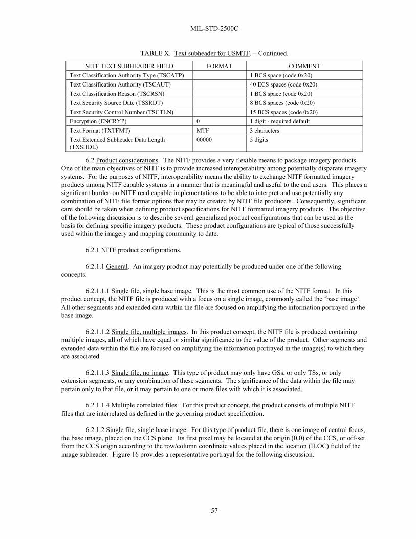
MIL-STD-2500C
57
TABLE X. Text subheader for USMTF. – Continued.
NITF TEXT SUBHEADER FIELD FORMAT COMMENT Text Classification Authority Type (TSCATP) 1 BCS space (code 0x20) Text Classification Authority (TSCAUT) 40 ECS spaces (code 0x20) Text Classification Reason (TSCRSN) 1 BCS space (code 0x20) Text Security Source Date (TSSRDT) 8 BCS spaces (code 0x20) Text Security Control Number (TSCTLN) 15 BCS spaces (code 0x20) Encryption (ENCRYP) 0 1 digit - required default Text Format (TXTFMT) MTF 3 characters Text Extended Subheader Data Length (TXSHDL)
00000 5 digits
6.2 Product considerations. The NITF provides a very flexible means to package imagery products. One of the main objectives of NITF is to provide increased interoperability among potentially disparate imagery systems. For the purposes of NITF, interoperability means the ability to exchange NITF formatted imagery products among NITF capable systems in a manner that is meaningful and useful to the end users. This places a significant burden on NITF read capable implementations to be able to interpret and use potentially any combination of NITF file format options that may be created by NITF file producers. Consequently, significant care should be taken when defining product specifications for NITF formatted imagery products. The objective of the following discussion is to describe several generalized product configurations that can be used as the basis for defining specific imagery products. These product configurations are typical of those successfully used within the imagery and mapping community to date.
6.2.1 NITF product configurations.
6.2.1.1 General. An imagery product may potentially be produced under one of the following concepts.
6.2.1.1.1 Single file, single base image. This is the most common use of the NITF format. In this product concept, the NITF file is produced with a focus on a single image, commonly called the ‘base image’. All other segments and extended data within the file are focused on amplifying the information portrayed in the base image.
6.2.1.1.2 Single file, multiple images. In this product concept, the NITF file is produced containing multiple images, all of which have equal or similar significance to the value of the product. Other segments and extended data within the file are focused on amplifying the information portrayed in the image(s) to which they are associated.
6.2.1.1.3 Single file, no image. This type of product may only have GSs, or only TSs, or only extension segments, or any combination of these segments. The significance of the data within the file may pertain only to that file, or it may pertain to one or more files with which it is associated.
6.2.1.1.4 Multiple correlated files. For this product concept, the product consists of multiple NITF files that are interrelated as defined in the governing product specification.
6.2.1.2 Single file, single base image. For this type of product file, there is one image of central focus, the base image, placed on the CCS plane. Its first pixel may be located at the origin (0,0) of the CCS, or off-set from the CCS origin according to the row/column coordinate values placed in the location (ILOC) field of the image subheader. Figure 16 provides a representative portrayal for the following discussion.

MIL-STD-2500C
58
1. Common Coordinate System Origin (0,0) 2. Image DLVL =100 ALVL =000 ILOC =45,50 A. Inset Image DLVL =110 ALVL =100 ILOC =50,300 B. Inset Graphic DLVL =120 ALVL =110 SLOC =250,-100 (Box & Arrow)
0,0
A
1
2
CCS COLUMNS
CCS ROWS
CCS Boundary as indicated by Complexity Level
B
FIGURE 16. Single file, single base image.
6.2.1.2.1 Image Segment (IS) overlays. Additional images, often called subimages or inset images, may be included as separate ISs in the file. The purpose of these images is to add information or clarity about the base image. Their placement in the CCS plane is controlled by the value of each segment’s ALVL and Location (LOC) row/column value. When overlay images are attached to the base image, the LOC value represents a row/column off-set in the CCS from the location specified by the base image row/column LOC value. If the overlay image is unattached to any other segment (ALVL=000), the overlay’s LOC value is a row/column off-set from the CCS origin (0,0).
6.2.1.2.2 Graphic Segment (GS) overlays. GSs are used to provide graphical (lines, polygons, ellipses, etc.) and textual annotation to the base image. The graphic representation is done using CGM. In a manner similar to IS overlays, the placement of graphics in the CCS plane is controlled by the value of each segment’s ALVL and LOC values. CGM has its own internal Cartesian coordinate space called “Virtual Display Coordinates (VDC)” that has its own defined origin (0,0) point. The row/column value in the GS LOC field identifies the placement of the graphic’s VDC origin point relative to the CCS origin when ALVL=000, or relative to the segment LOC to which it is attached.
6.2.1.2.3 Non-destructive overlays. NITF IS and GS overlays are handled in a non-destructive manner. The overlays may be placed anywhere within the bounds of the CCS (defined for a specific NITF file by the CLEVEL. They may be placed totally on the base image, partially on the base image, or entirely off of the base image. Any IS or GS can be placed on or under any other segment, fully or partially. The visibility of pixel values of overlapping segments is determined by the DLVL assigned to that segment. Each displayable segment (images and graphics) is assigned a DLVL (ranging from 001 to 999) that is unique within the file. At any CCS pixel location shared by more than one image or graphic, the visible pixel value is the one from the segment having the greatest DLVL value. If the user of an NITF file opts to move an overlay, or turn off the presentation of an overlay, the next greatest underlying pixel value(s) will then become visible. This approach allows for the non-destructible nature of NITF overlays as opposed to the ‘burned in’ approach where overlay pixel values are used to replace pixels values of the underlying image.

MIL-STD-2500C
59
6.2.1.2.4 Text Segment (TS). TSs allow inclusion in the NITF file of textual information related to the base image, perhaps a textual description of the activities portrayed in the image. For the purpose of this standard, segment refers to header or subheader and associated data. Below is a sample GRAPHREP text message:
EXER/GRAU MESSER// MSGID/GRAPHREP-OVERLAY/420TH MI BDE// OVERLAY/A/420TH MI BDE/24153000ZFEB98/OP AREA 3// GENTEXT/OVERLAY DESCRIPTION/THIS OVERLAY IDENTIFIES AN APACHE HELICOPTER IN OPERATION AREA 3// IMG/DTE:970223/PRJ:MI/MSN:C031/FR/56-61,68/-/TOT:1322Z/50000 /BEN:0173-99999/SFX:A123/CAT:80000// ICONID/A/421ST MI BDE/24190000ZFEB98/001/001/AFAPMHA00000000/E// EQUIP/APACHE/AIRCRAFT/MAIN// GRD/24190000ZFEB98/-/ACRCVR// ICONLOC/313448.0N1102032W/-/-/-/-/ELE:00370M/273T/0.OKPH//
6.2.1.2.5 Extension data. The NITF file header and each standard data type sub-header have designated expandable fields to allow for the optional inclusion of extension data. The inclusion of extension data provides the ability to add data/information about the standard data type (metadata) that is not contained in the basic fields of the headers and subheaders. The additional data is contained within one or more NITF TRE that are placed in the appropriate field (user defined data field or extended data field) of the standard data type subheader for which the metadata applies. When TRE have application across multiple data types in the file, or otherwise apply to the entire NITF file in general, they are placed in the appropriate file header fields. Whereas general purpose NITF readers should always be able to portray IS and GS and act on standard header and subheader data, they may not always be able to act on product specific extension data. Upon receipt of a file that contains extension data, an NITF compliant system should at least ignore the extensions and properly interpret the other legal components of the NITF file. Exemplary use of TRE:
a. Data about people, buildings, places, landmarks, equipment or other objects that may appear in the image.
b. Data to allow correlation of information among multiple images and annotations within an NITF file.
c. Data about the equipment settings used to obtain the digital image, x-ray, etc.
d. Data to allow geo-positioning of items in the imagery or measurement of distances of items in the imagery.
6.2.1.3 Single file, multiple images without overlap. For this type of product file, multiple images of equal or similar focus (multiple ‘base’ images) are placed within the CCS plane. Each image is located at an off-set from the CCS origin such that there is no overlap among the images. The CLEVEL of the file must be chosen such that the bounds of the CCS for the file are sufficient to contain the extent of all segments within the file. Figure 17 provides a representative portrayal for this product type.
6.2.1.3.1 Overlays. Each image may be overlaid with additional ISs and GSs in the same fashion as described for the single file, single image case above. All overlays associated with a specific image should be attached to that specific image. Display levels assigned to each image and graphic in the file must be unique within the file.

MIL-STD-2500C
60
6.2.1.3.2 Text Segment (TS). Each TS should be clearly marked as to whether it applies to the file as a whole, or if it is associated with specific images within the file. For the purpose of this standard, segment refers to header or subheader and associated data.
6.2.1.3.3 Extension data. TRE are placed in the file header extension fields when applicable to the file as a whole. Extensions specific to a segment are placed in that segment’s subheader.
6.2.1.4 Single file, no image. An NITF single file product does not always contain an image. It could contain one or more GSs, one or more TSs, one or more extension segments, or any combination of these non-ISs. The file may be useful as a stand alone product, or it may be intended for use in conjunction with other NITF files. For example, the file could contain graphic overlays to be merged with or applied to another NITF file that was prepositioned or transmitted at an earlier time. Any general purpose NITF reader should at least be able to interpret and render the standard segments of no image NITF files on a stand alone basis.
6.2.1.5 Multiple correlated files. An imagery product may be composed of multiple NITF files that are interrelated in a specified manner. This approach vastly increases the potential combination and permutation of options a general purpose NITF reader would need to support to maintain full interpret capability. Therefore, each NITF file in a multiple correlated file set must be structured such that a general purpose NITF reader can properly interpret and render the file as if it were a stand alone product. The correlation of multiple NITF files in a single product must be explicitly and unambiguously defined in a product specification. NITF readers can then be further categorized according to specific multiple file product specifications that are supported. Representative use of multiple correlated NITF files includes:
6.2.1.5.1 Stereo imagery. Some stereo image products are composed of separate NITF files for the stereo components of each image scene.
6.2.1.5.2 Imagery mosaics. Some extremely large image and map products consist of multiple NITF files structured such that they can be pieced together in mosaic fashion by the interpret application as if the multiple files were a single larger image.
6.2.1.5.3 Reduced resolution data sets (Rsets). Some Rset products are composed of multiple NITF files. One file contains a full resolution image and the other files contain the same image in a variety of lower resolutions.
6.2.1.5.4 Imagery and maps. Some geo-positioning products exist which consist of multiple separate NITF files containing interrelated maps, images, graphics, legends, product indices, and geo-reference data.

MIL-STD-2500C
61
1
2 3 4
5 6
7
AC
F
BD
E
G
H
0,0
J
CCS COLUMNS
CCS ROWS
CCS Boundary asindicated by ComplexityLevel
I
Display Attachment Location Level Level 1. Common Coordinate System Origin (0,0) 2. Image DL = 100 AL = 000 50, 50 (A) Image Segment Overlay DL = 110 AL = 100 50, 300 (B) Graphic Overlay DL = 120 AL = 110 100,-50 (CGM Rectangle & Arrow) 3. Image DL = 200 AL = 000 50, 550 4. Image DL = 300 AL = 000 50,1050 (C) Image Segment Overlay DL = 310 AL = 300 100, 450 (D) Graphic Segment Overlay DL = 320 AL = 300 300, 75 (CGM Rectangle) (E) Graphic Segment Overlay DL = 330 AL = 300 300,200 (CGM Arrow) 5 Image DL = 400 AL = 000 800, 50 6 Image DL = 500 AL = 000 800, 550 (F) Image Segment Overlay DL = 510 AL = 500 300, 300 (G) Graphic Segment Overlay DL = 520 AL = 500 35, 35 (CGM Rectangle) (H) Graphic Segment Overlay DL = 530 AL = 500 125, 125 (CGM Arrow) 7 Image DL = 600 AL = 000 820,1050 (I) Image Segment Overlay DL = 610 AL = 600 -150, 400 (J) CGM Graphic Overlay DL = 620 AL = 600 50, 100 (Rectangle & Arrow)
FIGURE 17. Single file, multiple images.

MIL-STD-2500C
62
6.3 Sample NITF file structure. The following is an example of handling a file that has control TRE with overflow. The file has a single image.
TABLE XI. Sample NITF file structure.
NITF FILE HEADER
IMAGE SUBHEADER
IMAGE DATA
DATA EXTENSION SUBHEADER
DATA EXTENSION
MAIN NITF HEADER IMAGE SUBHEADER DES SUBHEADER
N A M E
F H D R
C L E V E L
ETC
F L
H L
N U M I
L I S H 0 0 1
L I 0 0 1
N U M S
N U M X
N U M T
N U M D E S
L D S H 0 0 1
L D 0 0 1
N U MR E S
U D H D L
X H D L
I
M
ETC
I
MA G
U D I D L
I X S H D L
I X S O F L
I X S H D
I
MA G E
D A T A
D E
D E S T A G
ETC
D E S O F L W
D E S I T E M
D E S S H L
D E S
D A T A
B Y T E S
9
2
1 2
6
3
6
1 0
3
3
3
3
4
9
3
5
5
2
4
5
5
3
9 8 0 0 0
2
2 5
6
3
4
4 2 0 0 0
V A L U E
N S I F 0 1 . 0 0
0 6
0 0 0 8 0 5 0 7 5 7 6 4
0 0 0 4 1 7
0 0 1
0 9 8 4 4 2
0 0 8 4 9 3 4 6 5 6
0 0 0
0 0 0
0 0 0
0 0 1
0 2 4 9
0 0 0 0 4 2 0 0 0
0 0 0
0 0 0 0 0
0 0 0 0 0
I
M
1 . 0
0 0 0 0 0
9 8 0 0 3
0 0 1
D E
T R E
O V E R F L O W
U D I D
0 0 1
0 0 0 0
TRE 1 (32,000 BYTES)
TRE 4 (42,000 BYTES)
TRE 2 (27,000 BYTES)
TRE 3 (39,000 BYTES)
Note: Capacity of IXSHD is 99,999 bytes. You cannot split a TRE, therefore the first 3 TRE fit into the IXSHD and the 4th TRE is overflowed into the Data Extension Area.
6.4 Subject term (key word) listing.
Annotation, Imagery Blocked Image Mask Compression Algorithm Compression, Bi-Level Compression, Imagery Facsimile Compression File Format Graphics

MIL-STD-2500C
63
Grey Scale Imagery Group 3 Facsimile Image Image Compression Image Dissemination Image Transmission Imagery, Bi-Level Overlay Picture Quantization Matrices Raster Secondary Imagery Dissemination Systems SIDS Symbols Tag Fill Pixels Pad Pixel Pad Pixel Mask
6.5 Changes from previous issue. Marginal notations are not used in this revision to identify changes with respect to the previous issue due to the extent of the changes. Differences between NITF Version 2.0 and NITF Version 2.1 are described in NGA 0105-98.
6.5.1 Complexity Level 09. Added definition for Complexity Level 09 (CLEVEL 09) to table A-10 (see footnote). CLEVEL 09 is used to designate NITF 2.1 files that exceed the CLEVEL 07 constraints, but remain within the bounds of the standard.
6.5.2 Large Block Option. Added the 'large block option.' This option allows for an image array to be a single large block, or a single row of blocks that are large in the row dimension, or a single column of blocks that are large in the column dimension. See paragraph 5.4.2.2d and table A-3, fields NPPBH and NPPBV.
6.5.3 Spectral Data. Use of spectral data in NITF is expanding. Added clarification and minor enhancements based on 'lessons learned' as users have become more familiar with spectral data.
a) Allows IREP=MULTI to accommodate Signed Integer (SI) data that is now becoming available from commercial sources. See table A-2 row entry for MULTI and table A-2(A) row entry for MS/HS.
b) The standard now allows for NROWS or NCOLS values as small as "00000001" rather than "00000002" pixels. The need for a single pixel row, single pixel column, or single pixel image has arisen from users becoming more familiar with the application and use of spectral data. For example, allowing for 1x1 pixel image segments (perhaps with many bands) will accommodate NITF image segments holding a single pixel spectral signature or material classification profile. See table A-3 row entries for NROWS and NCOLS; and table A-10 row entry for Image Size.
c) Table A-3, IREPBANDn field; added the value of 'spaces' to the allowed value list when IREP=MULTI.

MIL-STD-2500C
64
6.5.4 JPEG 2000. Added information and clarification for application of the JPEG 2000 image compression standard within the NITFS.
a) Added references to ISO/IEC 15444, JPEG 2000; the BIIF Profile for JPEG 2000, Version 01.00; and the BIIF Profile for NATO Secondary Imagery Format (NSIF) Version 01.00. See paragraph 2.3.
b) Added clarification to table A-3 COMRAT field description when using JPEG 2000 compression. Similar JPEG 2000 clarifications were made for discussion on the IREP field (paragraph 5.4.1.1), Data Mask (paragraph 5.4.3.2), and IMODE field (table A-3).
c) Clarified the use and population of the NBPP and PVTYPE fields when using JPEG 2000 compression. See table A-3.
d) Added row entries to table A-10 to show the applicable CLEVEL constraints for use of JPEG 2000.
e) The standard now allows greater than 8 bit-per-band, 3 band, RGB imagery to be formatted uncompressed and displayed on systems that have not yet implemented JPEG-2000. This change also allows RGB color imagery generated by the latest commercial digital cameras and scanners to be stored uncompressed and marked RGB (IREP value) within the NITF format. See table A-10, row entry for Color (RGB), No Compression.
6.5.5 Number of allowed DES per file. Increased the number Data Extension Segments (DES) allowed in the various CLEVELs described in table A-10.
6.5.6 Date and Time Fields. Establishes a common convention for expressing incomplete date and/or time values. See paragraph 5.1.7d, table A-3 entry for the IDATIM field, and table A-6 entry for the TXTDT field.
6.5.7 POLAR values. Added a new row for POLAR to table A-10 for additional clarification.
6.5.8 Bi-Level optional. Added statement to Bi-Level entries in table A-10 to indicate that Bi-Level is now optional for implementation, but must follow the specifications when implemented.
6.5.9 Miscellaneous. Corrected a number of miscellaneous spelling, typographical, value range, omission, and editorial errors found in the document. Those documentation errors that potentially have technical implications for proper implementation of the standard include:
a) Added the image data mask table (TABLE A-3(A)) descriptions for IMODEs B, P and R that were inadvertently omitted in 2500B. Only IMODE S was described in 2500B.
b) Removed the CCS location (0,0) restriction from Paragraph 5.3.4, Attachment Level. The restriction was removed from the first version of 2500B, but was inadvertently re-introduced into 2500B/CN2. (This restriction was used in NITF 1.1 and NITF 2.0 but was found to needlessly restrict functionality of the format.)
c) Corrected several errors introduced in 2500B/CN2 in table A-10. The JPEG Lossless Compression Monochrome (MONO) row was inadvertently filled with Downsample JPEG information. In the Bi-level compression (MONO) row, the maximum number of pixels per row and column were reversed. Also removed the "/" in the notation of "Single Band/Block" to clarify the meaning to be Singe Band and Single Block vice Single Band Per Block. In the VQ compression row, removed "/Block" to clarify VQ imagery supports both single and multiple blocks, VQ image segments are not constrained to be a single block.

MIL-STD-2500C
65
d) Table A-2, row entry for MONO; added the value for 'spaces' to the value list in the IREPBANDn field.
e) Table A-3, PVTYPE field; added the value of '12' to the list of bit-per-pixel limitations for INT and SI data types.
f) Table A-3, COMRAT field; corrected placement of decimal point in template for expressing compression rate for VQ compressed data.
g) Table A-10, row entry for Elevation Data (NODISPLY), added compression code NM to allow masked tables in support of data voids.
6.10 SI values for SAR/SARIQ. Extend allowed range of PVTYPE for SARIQ by including SI for SAR imagery products. See table A-2(A) row entry for SAR/SARIQ.
6.11 Matrix Data (NODISPLY). Increased the number of bands allowed in the various CLEVELs described in table A-10.
6.12 Header/subheader field specification. Added information for submitting new header, subheader, and TRE field values.
6.13 IGEOLO. Clarfied the use of IGEOLO when ICORDS is populated with a BCS space. IGEOLO field is not present if there is no coordinate system identified in the ICORDS field.
6.14 IMAG. Expands reciprocal value to any non-negative integer, not just powers of 2. This allows for greater precision when determining the magnification or reduction of the image segment.
6.15 Fill/Pad Pixel. Defines and separates two different functions. Fill pixels are used in blocked images that are stored or transmitted when NROWS and/or NCOLS are not integer multiples of image block size and do not impact display. Pad pixels are recorded in order to maintain the pattern of the pixel array and does impact display.

MIL-STD-2500C
66
APPENDIX A
NITF TABLES
A.1 SCOPE
This appendix is a mandatory part of this standard. The information contained herein is intended for compliance.
A.2 APPLICABLE DOCUMENTS
This section is not applicable to this appendix.
A.3 DEFINITIONS
The definitions in section 3 of this standard apply to this appendix.
A.4 DETAILED REQUIREMENTS
TABLE A-1. NITF file header. (TYPE “R” = Required, “C” = Conditional, “< >“ = BCS spaces allowed for entire field)
(“†” annotations are explained at the end of the table) FIELD NAME SIZE VALUE RANGE TYPE
FHDR File Profile Name. This field shall contain the BCS-A character string uniquely denoting that the file is formatted using NITF. The valid value for this field is NITF.
4 BCS-A NITF
R
FVER File Version. This field shall contain a BCS-A character string uniquely denoting the version. The valid value for this field is 02.10.
5 BCS-A 02.10
R
CLEVEL Complexity Level. This field shall contain the complexity level required to interpret fully all components of the file. Valid entries are assigned in accordance with complexity levels established in Table A-10.
2 BCS-N positive integer 01 to 99
R
STYPE Standard Type. Standard type or capability. A BCS-A character string BF01 which indicates that this file is formatted using ISO/IEC IS 12087-5. NITF02.10 is intended to be registered as a profile of ISO/IEC IS 12087-5.
4 BCS-A BF01
R
OSTAID Originating Station ID. This field shall contain the identification code or name of the originating organization, system, station, or product. It shall not be filled with BCS spaces (0x20).
10 BCS-A R
FDT File Date and Time. This field shall contain the time (UTC) (Zulu) of the file’s origination in the format CCYYMMDDhhmmss, where CC is the century (00 to 99), YY is the last two digits of the year (00 to 99), MM is the month (01 to 12), DD is the day (01 to 31), hh is the hour (00 to 23), mm is the minute (00 to 59), and ss is the second (00 to 59). UTC is assumed to be the time zone designator to express the time of day.
14 BCS-N integer CCYYMMDDhhmmss
R

MIL-STD-2500C APPENDIX A
67
TABLE A-1. NITF file header - Continued.
FIELD NAME SIZE VALUE RANGE TYPE FTITLE File Title. This field shall contain the title of the file or
shall be filled with ECS spaces (0x20). 80 ECS-A
(Default is ECS spaces (0x20))
<R>
FSCLAS File Security Classification. This field shall contain a valid value representing the classification level of the entire file. Valid values are T (=Top Secret), S (=Secret), C (=Confidential), R (=Restricted), U (=Unclassified).
1 ECS-A T, S, C, R, or U
R
NOTE: If FSCLAS is T, S, C, or R, then FSCLSY must be populated with a valid code for the security classification system used. FSCLSY File Security Classification System. This field shall
contain valid values indicating the national or multinational security system used to classify the file. Country Codes per FIPS PUB 10-4 shall be used to indicate national security systems. The designator "XN" is for classified data generated by a component using NATO security system marking guidance. This code is outside the FIPS 10-4 document listing, and was selected to not duplicate that document's existing codes. If this field is all ECS spaces (0x20), it shall imply that no security classification system applies to the file.
2 ECS-A (Default is ECS spaces (0x20))
<R>
NOTE: If any of the following fields are populated with anything other than spaces, then FSCLSY must be populated with a valid code for the security classification system used: FSCODE, FSREL, FSDCTP, FSDCDT, FSDCXM, FSDG, FSDGDT, FSCLTX, FSCATP, FSCAUT, FSCRSN, FSSRDT, and FSCTLN. FSCODE File Codewords. This field shall contain a valid
indicator of the security compartments associated with the file. Values include one or more of the digraphs found table A-4. Multiple entries shall be separated by a single ECS space (0x20): The selection of a relevant set of codewords is application specific. If this field is all ECS spaces (0x20), it shall imply that no codewords apply to the file.
11 BCS-A (Default is BCS spaces (0x20))
<R>
FSCTLH File Control and Handling. This field shall contain valid additional security control and/or handling instructions (caveats) associated with the file. Values include digraphs found in table A-4. The digraph may indicate single or multiple caveats. The selection of a relevant caveat(s) is application specific. If this field is all ECS spaces (0x20), it shall imply that no additional control and handling instructions apply to the file.
2 ECS-A (Default is ECS spaces (0x20))
<R>
FSREL File Releasing Instructions. This field shall contain a valid list of country and/or multilateral entity codes to which countries and/or multilateral entities the file is authorized for release. Valid items in the list are one or more country codes as found in FIPS PUB 10-4 separated by a single ECS space (0x20). If this field is all ECS spaces (0x20), it shall imply that no file release instructions apply.
20 ECS-A (Default is ECS spaces (0x20))
<R>

MIL-STD-2500C APPENDIX A
68
TABLE A-1. NITF file header - Continued.
FIELD NAME SIZE VALUE RANGE TYPE FSDCTP File Declassification Type. This field shall contain a
valid indicator of the type of security declassification or downgrading instructions which apply to the file. Valid values are DD (=declassify on a specific date), DE (=declassify upon occurrence of an event), GD (=downgrade to a specified level on a specific date), GE (=downgrade to a specified level upon occurrence of an event), O (=OADR), and X (= exempt from automatic declassification). If this field is all ECS spaces (0x20), it shall imply that no file security declassification or downgrading instructions apply.
2 ECS-A DD, DE, GD, GE, O, X (Default is ECS spaces (0x20))
<R>
FSDCDT File Declassification Date. This field shall indicate the date on which a file is to be declassified if the value in File Declassification Type is DD. If this field is all ECS spaces (0x20), it shall imply that no file declassification date applies.
8 ECS-A CCYYMMDD (Default is ECS spaces (0x20))
<R>
FSDCXM File Declassification Exemption. This field shall indicate the reason the file is exempt from automatic declassification if the value in File Declassification Type is X. Valid values are X1 to X8 and X251 to X259. X1 to X8 correspond to the declassification exemptions found in DOD 5200.1-R, paragraphs 4-202b(1) to (8) for material exempt from the 10-year rule. X251 to X259 correspond to the declassification exemptions found in DOD 5200.1-R, paragraphs 4-301a(1) to (9) for permanently valuable material exempt from the 25-year declassification system. If this field is all ESC spaces (0x20), it shall imply that a file declassification exemption does not apply.
4 ECS-A X1 to X8, X251 to X259, (Default is ECS spaces (0x20))
<R>
FSDG File Downgrade. This field shall indicate the classification level to which a file is to be downgraded if the values in File Declassification Type are GD or GE. Valid values are S (=Secret), C (=Confidential), R (= Restricted). If this field contains an ECS space (0x20), it shall imply that file security downgrading does not apply.
1 ECS-A S, C, R (Default is ECS space (0x20))
<R>
FSDGDT File Downgrade Date. This field shall indicate the date on which a file is to be downgraded if the value in File Declassification Type is GD. If this field is all ECS spaces (0x20), it shall imply that a file security downgrading date does not apply.
8 ECS-A CCYYMMDD (Default is ECS spaces (0x20))
<R>
FSCLTX File Classification Text. This field shall be used to provide additional information about file classification to include identification of a declassification or downgrading event if the values in File Declassification Type are DE or GE. It may also be used to identify multiple classification sources and/or any other special handling rules. Values are user defined free text. If this field is all ECS spaces (0x20), it shall imply that additional information about file classification does not apply.
43 ECS-A (Default is ECS spaces (0x20))
<R>
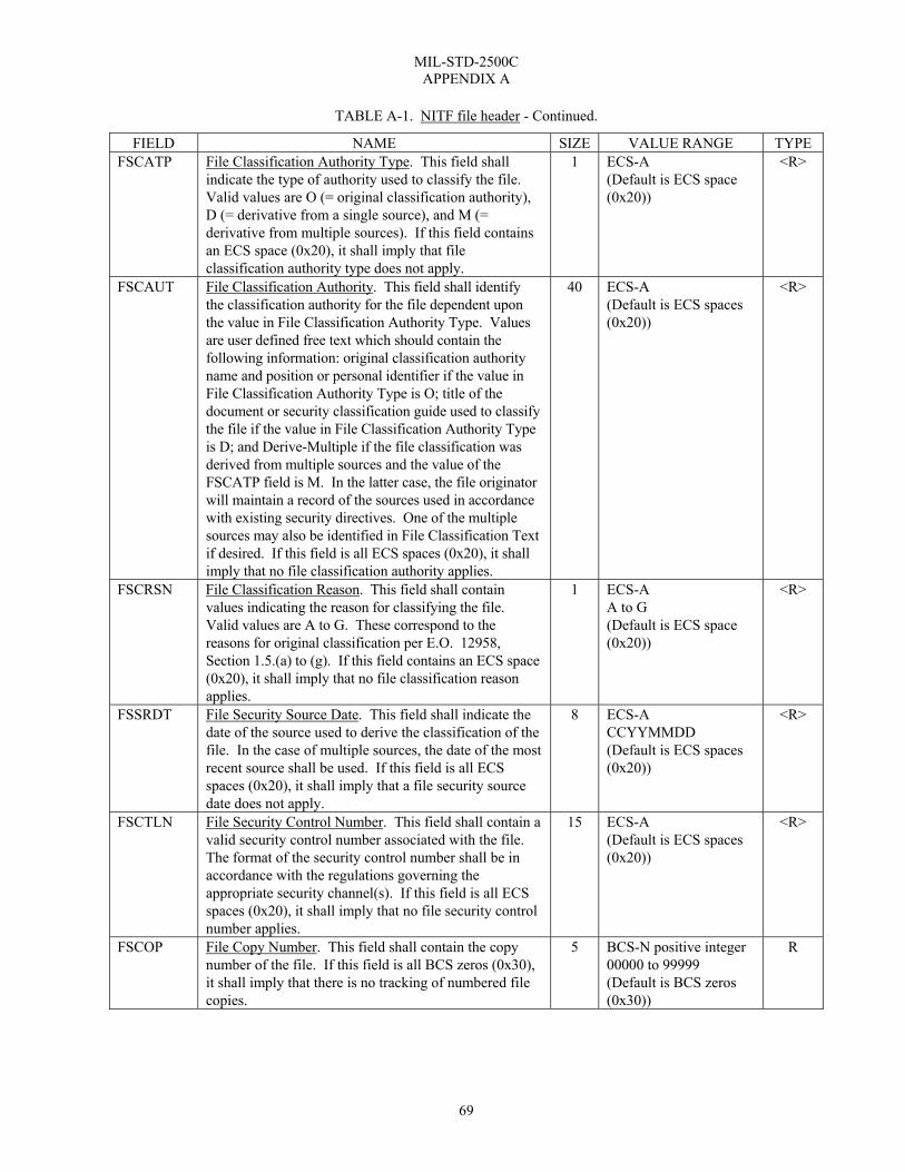
MIL-STD-2500C APPENDIX A
69
TABLE A-1. NITF file header - Continued.
FIELD NAME SIZE VALUE RANGE TYPE FSCATP File Classification Authority Type. This field shall
indicate the type of authority used to classify the file. Valid values are O (= original classification authority), D (= derivative from a single source), and M (= derivative from multiple sources). If this field contains an ECS space (0x20), it shall imply that file classification authority type does not apply.
1 ECS-A (Default is ECS space (0x20))
<R>
FSCAUT File Classification Authority. This field shall identify the classification authority for the file dependent upon the value in File Classification Authority Type. Values are user defined free text which should contain the following information: original classification authority name and position or personal identifier if the value in File Classification Authority Type is O; title of the document or security classification guide used to classify the file if the value in File Classification Authority Type is D; and Derive-Multiple if the file classification was derived from multiple sources and the value of the FSCATP field is M. In the latter case, the file originator will maintain a record of the sources used in accordance with existing security directives. One of the multiple sources may also be identified in File Classification Text if desired. If this field is all ECS spaces (0x20), it shall imply that no file classification authority applies.
40 ECS-A (Default is ECS spaces (0x20))
<R>
FSCRSN File Classification Reason. This field shall contain values indicating the reason for classifying the file. Valid values are A to G. These correspond to the reasons for original classification per E.O. 12958, Section 1.5.(a) to (g). If this field contains an ECS space (0x20), it shall imply that no file classification reason applies.
1 ECS-A A to G (Default is ECS space (0x20))
<R>
FSSRDT File Security Source Date. This field shall indicate the date of the source used to derive the classification of the file. In the case of multiple sources, the date of the most recent source shall be used. If this field is all ECS spaces (0x20), it shall imply that a file security source date does not apply.
8 ECS-A CCYYMMDD (Default is ECS spaces (0x20))
<R>
FSCTLN File Security Control Number. This field shall contain a valid security control number associated with the file. The format of the security control number shall be in accordance with the regulations governing the appropriate security channel(s). If this field is all ECS spaces (0x20), it shall imply that no file security control number applies.
15 ECS-A (Default is ECS spaces (0x20))
<R>
FSCOP File Copy Number. This field shall contain the copy number of the file. If this field is all BCS zeros (0x30), it shall imply that there is no tracking of numbered file copies.
5 BCS-N positive integer 00000 to 99999 (Default is BCS zeros (0x30))
R

MIL-STD-2500C APPENDIX A
70
TABLE A-1. NITF file header - Continued.
FIELD NAME SIZE VALUE RANGE TYPE FSCPYS File Number of Copies. This field shall contain the total
number of copies of the file. If this field is all BCS zeros (0x30), it shall imply that there is no tracking of numbered file copies.
5 BCS-N positive integer 00000 to 99999 (Default is BCS zeros (0x30))
R
ENCRYP Encryption. This field shall contain the value BCS zero (0x30) until such time as this specification is updated to define the use of other values.
1 BCS-N positive integer (Default is BCS zero (0x30)) 0 = Not Encrypted
R
FBKGC File Background Color. This field shall contain the three color components of the file background in the order Red, Green, Blue. Where (0x00, 0x00, 0x00) is black and (0xFF, 0xFF, 0xFF) is white.
3 Unsigned binary integer (0x00 to 0xFF, 0x00 to 0xFF, 0x00 to 0xFF)
R
ONAME Originator’s Name. This field shall contain a valid name for the operator who originated the file. If the field is all ECS spaces (0x20), it shall represent that no operator is assigned responsibility for origination.
24 ECS-A (Default is ECS spaces (0x20))
<R>
OPHONE Originator’s Phone Number. This field shall contain a valid phone number for the operator who originated the file. If the field is all ECS spaces (0x20), it shall represent that no phone number is available for the operator assigned responsibility for origination.
18 ECS-A (Default is ECS spaces (0x20))
<R>
FL File Length. This field shall contain the length in bytes of the entire file including all headers, subheaders, and data. Note: The largest file is limited to 999999999998 (1012 -2) bytes. A value of 999999999999 in this field indicates that the actual file length was not available when the header was created (paragraph 5.2.1).
12 BCS-N positive integer 000000000388 to 999999999998, 999999999999
R
HL NITF File Header Length. This field shall contain a valid length in bytes of the NITF file header.
6 BCS-N positive integer 000388 to 999999
R
NUMI Number of Image Segments. This field shall contain the number of separate image segments included in the file. This field shall be BCS zeros (0x30) no image segments are included in the file.
3 BCS-N positive integer (Default is BCS zeros (0x30)) 000 to 999
R
. . . . . Start for each IS LISHn, LIn. NOTE: LISHn and LIn fields repeat in pairs such that LISH001, LI01; LISH002, LI002; .....LISHn,LIn. LISHn Length of nth Image Subheader. This field shall contain
a valid length in bytes for the nth image subheader, where n is the number of the IS counting from the first IS (n=001) in order of the image segments’ appearance in the file. Possible values for n are 001 to 999. This field shall occur as many times as specified in the NUMI field. This field is conditional and shall be omitted if the NUMI field contains BCS zeros (0x30). Note: The largest image subheader is limited to 999998 (106 -2) bytes. A value of 999999 in this field indicates that the actual subheader length was not available when the header was created (paragraph 5.2.1).
6 BCS-N positive integer 000439 to 999998, 999999
C

MIL-STD-2500C APPENDIX A
71
TABLE A-1. NITF file header - Continued.
FIELD NAME SIZE VALUE RANGE TYPE LIn Length of nth Image Segment. This field shall contain a
valid length in bytes of the nth IS, where n is the number of the IS counting from the first IS(n=001) in order of the IS appearance in the file. Possible values for n are 001 to 999. If the IS is compressed, the length after compression shall be used. This field shall occur as many times as specified in the NUMI field. This field is conditional and shall be omitted if the NUMI field contains BCS zeros (0x30). Note: The largest image is limited to 9999999998 (1010 -2) bytes. A value of 9999999999 in this field indicates that the actual image length was not available when the header was created (paragraph 5.2.1).
10 BCS-N positive integer 0000000001 to 9999999998, 9999999999
C
. . . . End for each IS LISHn, LIn; the number of loop repetitions is the value specified in the NUMI field. NUMS Number of Graphic Segments. This field shall contain
the number of separate graphic segments included in the file. This field shall be BCS zeros (0x30) if no graphic segments are included in the file.
3 BCS-N positive integer 000 to 999
R
. . . . . Start for each GS LSSHn, LSn. NOTE: LSSHn and LSn fields repeat in pairs such that LSSH001, LS00; LSSH001, LS002; .....LSSHn,LSn. LSSHn Length of nth Graphic Subheader. This field shall contain
a valid length in bytes for the nth graphic subheader, where n is the number of the graphic segment counting from the first GS (n=001) in the order of the graphic segments’ appearance in the file. Possible values for n are 001 to 999. This field shall occur as many times as specified in the NUMS field. This field is conditional and shall be omitted if the NUMS contains BCS zeros (0x30). Note: The largest subheader is limited to 9998 (104 -2) bytes. A value of 9999 in this field indicates that the actual subheader length was not available when the header was created (paragraph 5.2.1).
4 BCS-N positive integer 0258 to 9998, 9999
C
LSn Length of nth Graphic Segment. This field shall contain a valid length in bytes of the nth GS, where n is the number of the GS, counting from the first GS (n=001) in the order of the graphic segments’ appearance in the file. Possible values for n are 001 to 999. This field shall occur as many times as specified in the NUMS field. This field is conditional and shall be omitted if NUMS field contains BCS zeros (0x30). Note: The largest graphic is limited to 999998 (106 -2) bytes. A value of 999999 in this field indicates that the actual graphic length was not available when the header was created (paragraph 5.2.1).
6 BCS-N positive integer 000001 to 999998, 999999
C
. . . . End for each GS LSSHn, LSn; the number of loop repetitions is the value specified in the NUMS field. NUMX Reserved for Future Use. This field is reserved for
future use and shall be filled with BCS zeros (0x30). 3 BCS-N positive integer
000 R
NUMT Number of Text Segments. This field shall contain the number of separate text segment(s) included in the file. This field shall be BCS zeros (0x30) if no text segments are included in the file.
3 BCS-N positive integer (Default is BCS zeros (0x30)) 000 to 999
R

MIL-STD-2500C APPENDIX A
72
TABLE A-1. NITF file header - Continued.
FIELD NAME SIZE VALUE RANGE TYPE . . . . . Start for each TS LTSHn, LTn. NOTE: LTSHn and LTn fields repeat in pairs such that LTSH001, LT00; LTSH001, LT002; .....LTSHn,LTn. LTSHn Length of nth text subheader. This field shall contain a
valid length in bytes for the nth text subheader, where n is the number of the text segment, counting from the first text segment (n=001) in the order of the text segments’ appearance in the file. Possible values for n are 001 to 999. This field shall occur as many times as specified in the NUMT field. This field is conditional and shall be omitted if the NUMT field contains BCS zeros (0x30). Note: The largest subheader is limited to 9998 (104 -2) bytes. A value of 9999 in this field indicates that the actual subheader length was not available when the header was created (paragraph 5.2.1).
4 BCS-N positive integer 0282 to 9998, 9999
C
LTn Length of nth Text Segment. This field shall contain a valid length in bytes of the nth text segment, where n is the number of the text segment, counting from the first text segment (n=001) in the order of the text segments’ appearance in the file. Possible values for n are 001 to 999. This field shall occur as many times as specified in the NUMT field. This field is conditional and shall be omitted if the NUMT field contains BCS zeros (0x30). Note: The largest text file is limited to 9998 (105 -2) bytes. A value of 99999 in this field indicates that the actual text file length was not available when the header was created (paragraph 5.2.1).
5 BCS-N positive integer 00001 to 99998, 99999
C
. . . . End for each TS LTSHn, LTn; the number of loop repetitions is the value specified in the NUMT field. NUMDES Number of Data Extension Segments. This field shall
contain the number of separate DES included in the file. This field shall be BCS zeros (0x30) if no DES are included in the file.
3 BCS-N positive integer (Default is BCS zeros (0x30)) 000 to 999
R
. . . . . Start for each DES LDSHn, LDn. NOTE: LDSHn and LDn fields repeat in pairs such that LDSH001, LD00; LDSH001, LD002; .....LDSHn,LDn. LDSHn Length of nth Data Extension Segment Subheader. This
field shall contain a valid length in bytes for the nth DES subheader, where n is the number of the DES counting from the first DES (n = 001) in order of the DES’s appearance in the file. Possible values for n are 001 to 999. This field shall occur as many times as are specified in the NUMDES field. This field is conditional and shall be omitted if the NUMDES field contains BCS zeros (0x30). Note: The largest subheader is limited to 9998 (104 -2) bytes. A value of 9999 in this field indicates that the actual subheader length was not available when the header was created (paragraph 5.2.1).
4 BCS-N positive integer 0200 to 9998, 9999
C

MIL-STD-2500C APPENDIX A
73
TABLE A-1. NITF file header - Continued.
FIELD NAME SIZE VALUE RANGE TYPE LDn Length of nth Data Extension Segment. This field shall
contain a valid length in bytes of the data in the nth DES, where n is the number of the DES counting from the first DES (n=001) in order of the DES’ appearance in the file. This field shall occur as many times as are specified in the NUMDES field. This field is conditional and shall be omitted if the NUMDES fields contains BCS zeros (0x30). Note: The largest DES is limited to 999999998 (109 -2) bytes. A value of 999999999 in this field indicates that the actual DES length was not available when the header was created (paragraph 5.2.1).
9 BCS-N positive integer 000000001 to 999999998, 999999999
C
. . . . End for each DES LDSHn, LDn; the number of loop repetitions is the value specified in the NUMDES field. NUMRES Number of Reserved Extension Segments. This field
shall contain the number of separate RES included in the file. This field shall be BCS zeros (0x30) if no RES are included in the file.
3 BCS-N positive integer (Default is BCS zeros (0x30)) 000 to 999
R
. . . . . Start for each RES LRESHn, LREn. NOTE: LRESHn and LREn fields repeat in pairs such that LRESH001, LRE001; LRESH001, LRE002; .....LRESHn,LREn. LRESHn Length of nth Reserved Extension Segment Subheader.
This field shall contain a valid length in bytes for the nth RES subheader, where n is the number of the RES counting from the first RES (n = 001) in order for RES’ appearance in the file. This field shall occur as many times as are specified in the NUMRES field. This field is conditional and shall be omitted if the NUMRES field contains BCS zeros (0x30).
4 BCS-N positive integer 0200 to 9999
C
LREn Length of nth Reserved Extension Segment. This field shall contain a valid length in bytes for the nth RES subheader, where n is the number of the RES counting from the first RES (n=001) in order of the RES appearance in the file. This field shall occur as many times as are specified in the NUMRES field. This field is conditional and shall be omitted if the NUMRES field contains BCS zeros (0x30).
7 BCS-N positive integer 0000001 to 9999999
C
. . . . End for each RES LRESHn, LREn; the number of loop repetitions is the value specified in the NUMRES field. UDHDL User Defined Header Data Length. A value of BCS
zeros (0x30) shall represent that no TRE are included in the UDHD. If a TRE exists, the field shall contain the sum of the length of all the TRE (paragraph 5.8.1) appearing in the UDHD field plus 3 bytes (length of UDHOFL field). If a TRE is too long to fit in the UDHD field, it shall be put in the TRE overflow DES with DESID set to the value TRE_OVERFLOW (paragraph 5.8.3.1).
5 BCS-N positive integer (Default is BCS zeros (0x30)) 00000, 00003 to 99999
R
UDHOFL User Defined Header Overflow. This field shall contain BCS zeros (0x30) if the TRE in UDHD do not overflow into a DES, or shall contain the sequence number of the DES into which they do overflow. This field shall be omitted if the field UDHDL contains BCS zeros (0x30).
3 BCS-N positive integer (Default is BCS zeros (0x30)) 000 to 999
C

MIL-STD-2500C APPENDIX A
74
TABLE A-1. NITF file header - Continued.
FIELD NAME SIZE VALUE RANGE TYPE UDHD User-Defined Header Data. If present, this field shall
contain user-defined TRE data (paragraph 5.8.1). The length of this field shall be the value contained by the UDHDL field minus 3 bytes. Tagged record extensions shall appear one after the other with no intervening bytes. The first byte of this field shall be the first byte of the first tagged record extension appearing in the field. The last byte of this field shall be the last byte of the last tagged record extension to appear in the field. This field shall be omitted if the UDHDL field contains BCS zeros (0x30).
†1 User-defined C
XHDL Extended Header Data Length. A value of BCS zeros (0x30) shall represent that no TRE are included in the XHD. If a TRE exists, the field shall contain the sum of the length of all the TRE (paragraph 5.8.1) appearing in the XHD field plus 3 bytes (length of XHDLOFL field). If a TRE is too long to fit in the XHD field or the UDHD field it shall be put in the TRE overflow DES with DESID set to the value TRE_OVERFLOW (paragraph 5.8.3.1).
5 BCS-N positive integer (Default is BCS zeros (0x30)) 00000, 00003 to 99999
R
XHDLOFL Extended Header Data Overflow. This field shall contain BCS zeros (0x30) if the TRE in XHD do not overflow into a DES, or shall contain the sequence number of the DES into which they do overflow. This field shall be omitted if the XHDL field contains BCS zeros (0x30).
3 BCS-N positive integer (Default is BCS zeros (0x30)) 000 to 999
C
XHD Extended Header Data. If present, this field shall contain TRE (paragraph 5.8.1) approved and under configuration management of the ISMC. The length of this field shall be the length specified by the field XHDL minus 3 bytes. TRE shall appear one after the other with no intervening bytes. The first byte of this field shall be the first byte of the first TRE appearing in the field. The last byte of this field shall be the last TRE to appear in the field. This field shall be omitted if the XHDL field contains BCS zeros (0x30).
††1 TRE C
†1 A value as specified in the UDHDL field minus 3 (in bytes) ††1 A value as specified in the XHDL field minus 3 (in bytes)
TABLE A-2. Display dependent parameters.
IREP IREPBANDn NBANDS PVTYPE NLUTSn NODISPLY BCS spaces (0x20) 1 to 9, 0†2 INT, R,C,B, SI 0 MONO LU, M, BCS spaces (0x20) 1 INT, R,B 0, 1, 2 RGB R,G,B 3 INT, R 0 RGB/LUT LU 1 INT, B 3 YCbCr601 Y,Cb,Cr 3 INT 0 NVECTOR BCS spaces (0x20) 1 to 9, 0†2 INT, R,C 0 POLAR BCS spaces (0x20), M 2 INT, R,C 0 VPH BCS spaces (0x20) 2 INT, R,C 0 MULTI BCS spaces (0x20), M, R, G, B, LU 2 to 9, 0†2 INT, R,C,B, SI 0, 1, 2, 3
†2 If NBANDS field contains 0 then XBANDS field is required where XBANDS>9

MIL-STD-2500C APPENDIX A
75
TABLE A-2(A). Category dependent parameters. ICAT ISUBCATn NBANDS PVTYPE NBPP ABPP
1 B 1 1 8 2 to 8 12 8 to 12 16 9 to 16 32 17 to 32
INT
64 33 to 64 32 32
VIS, OP BCS spaces (0x20) User Defined 1, 3
R 64 64 8 2 to 8 12 8 to 12 16 9 to 16 32 17 to 32
INT
64 33 to 64 32 32
SL, TI, FL, RD, EO, HR, BP, FP, VD, CAT, MRI, XRAY
BCS spaces (0x20) User Defined
1
R 64 64 8 2 to 8 12 8 to 12 16 9 to 16 32 17 to 32
INT
64 33 to 64 32 32
IR BCS spaces (0x20), wave-length (in nanometers)
1
R 64 64 8 2 to 8 32 17 to 32
CP, PAT
BCS spaces (0x20) User Defined
3 INT
64 33 to 64 8 2 to 8 32 17 to 32
MAP, LEG
BCS spaces (0x20) User Defined
1, 3 INT
64 33 to 64 8 2 to 8 12 8 to 12 16 9 to 16 32 17 to 32
INT
64 33 to 64 8 2 to 8 12 8 to 12 16 9 to 16 32 17 to 32
SI
64 33 to 64 32 32
LOCG CGX, CGY, GGX, or GGY 2
R 64 64

MIL-STD-2500C APPENDIX A
76
TABLE A-2(A). Category dependent parameters – Continued.
ICAT ISUBCATn NBANDS PVTYPE NBPP ABPP C 64 64
8 2 to 8 12 8 to 12 16 9 to 16 32 17 to 32
INT
64 33 to 64 8 2 to 8 12 8 to 12 16 9 to 16 32 17 to 32
SI
64 33 to 64 32 32
MATR FACC codes from DIGEST Part 4, Annex B
1 to 9, 0†2(A)
R 64 64 8 2 to 8 12 8 to 12 16 9 to 16 32 17 to 32
INT
64 33 to 64 8 2 to 8 12 8 to 12 16 9 to 16 32 17 to 32
SI
64 33 to 64 32 32
MS, HS wave-length (in nanometers) 2 to 9, 0†2(A)
R 64 64
SAR, SARIQ 1 C 64 64 8 2 to 8 12 8 to 12 16 9 to 16 32 17 to 32
INT
64 33 to 64 8 2 to 8 12 8 to 12 16 9 to 16 32 17 to 32
SI
64 33 to 64 32 32
I, Q, M, P, or BCS Spaces 1, 2
R 64 64
WIND, CURRENT
SPEED, DIRECT 2 INT 8 2 to 8
BARO, 8 2 to 8 DEPTH 12 8 to 12
units in DIGEST Part 3 – 7 1 INT
16 9 to 16 8 8 12 8 to 12 16 9 to 16 32 17 to 32
DTEM units in DIGEST Part 3 – 7 1 INT
64 33 to 64

MIL-STD-2500C APPENDIX A
77
TABLE A-2(A). Category dependent parameters – Continued.
ICAT ISUBCATn NBANDS PVTYPE NBPP ABPP 8 8 12 12 16 16 32 32
SI
64 64 32 32
R 64 64
†2(A) If NBANDS field contains 0 then XBANDS field is required where XBANDS > 9
TABLE A-2(B). Image Category (ICAT) value definitions. ICAT DEFINITION
BARO Barometric Pressure. BP Black/White Frame Photography. The film or imagery produced by a black/white camera to
produce planimetric and topographic maps of the earth’s surface; includes surveying cameras, hand-held camera, and most reconnaissance cameras.
CAT Computerized Axial Tomography Scan. Cat Scans represent specialized x-rays of cross-sectional images from within the body; used for medical diagnosis.
CP Color Frame Photography. The film or imagery produced by a color camera to produce planimetric and topographic maps of the earth’s surface; includes surveying cameras, hand-held camera, and most reconnaissance cameras.
CURRENT Water Current. DEPTH Water Depth. DTEM Elevation Model. A numerical model of the elevations of points on the earth's surface. EO Electro-optical. Electro-Optical sensing systems sense things a film camera cannot see by using a
wider range of the electromagnetic spectrum. FL Forward Looking Infrared. Forward Looking Infrared is an airborne, electro-optical thermal
imaging device that detects far-infrared energy, converts the energy into an electronic signal, and provides a visible image for day or night viewing.
FP Fingerprints. Fingerprints used for identification which represent the markings on the inner surface of the fingertip, particularly when made with ink.
HR High Resolution Radar. High Resolution Radar which has been attenuated to take advantage of maximum pulse length and antenna beamwidth.
HS Hyperspectral. Hyperspectral imagery or imagery with narrow bandwidth and hundreds of bands; compare/contrast with monochromatic, multispectral, and ultraspectral.
IR Infrared. That imagery produced as a result of sensing electromagnetic radiation emitted or reflected from a given target surface in the infrared position of the electromagnetic spectrum (approximately 0.72 to 1,000 microns).
LEG Legends. Legends - Textual data that provides reference amplification for images. LOCG Location Grid. Location Grid - geolocation of an image within a frame. MAP Raster Map. Raster Maps result from the numerical process that scans contiguous pixel values to
produce an image representation. MATR Matrix Data. Geometric Data other than terrain and elevation.

MIL-STD-2500C APPENDIX A
78
TABLE A-2(B). Image Category (ICAT) value definitions - Continued.
ICAT DEFINITION MRI Magnetic Resonance Imagery. Magnetic Resonance Imagery is imagery formed from the response
of electrons, atoms, molecules, or nuclei to discrete radiation frequencies. MS Multispectral. Multispectral imagery or imagery from an object obtained simultaneously in a
number of discrete spectral bands. OP Optical. Optical imagery is captured using the principle of a focal plane intersecting an optical axis
in a film camera. PAT Color Patch. Color Patch usually accompanied with a Look-up-Table (LUT) to equate colors to an
image. RD Radar. Radar or Radio Detection and Ranging is imagery produced by recording radar waves
reflected from a given target surface. SAR Synthetic Aperture Radar. Synthetic Aperture Radar is radar which overcomes image resolution
deficiencies by using a short physical antenna to synthesize the effect of a very large antenna giving increased beamwidth.
SARIQ Synthetic Aperture Radar Radio Hologram. Radio hologram (initial phase information) from a Synthetic Aperture Radar (SAR) with 13,000 elements/slant range.
SL Side Looking Radar. Side-Looking Radar represents An airborne radar, viewing at right angles to the axis of the vehicle, which produces a presentation of terrain or moving targets.
TI Thermal Infrared. Thermal Infrared is imagery produced by sensing and recording the thermal energy emitted or reflected from the objects which are imaged.
VD Video. Video imagery is motion Imagery defined as imaging sensor / systems that generate sequential or continuous streaming images at specified temporal rates (normally expressed as frames per second).
VIS Visible Imagery. Visible Imagery in the electromagnetic spectrum that is visible to the human eye, usually between .4 and .7 micrometers; this type of imagery is usually captured via digital aerial photographs.
WIND Air Wind Charts. XRAY X-ray. A form of electromagnetic radiation, similar to light but of shorter wavelength.
TABLE A-3. NITF image subheader. (TYPE “R” = Required, “C” = Conditional, “< >“ = BCS spaces allowed for entire field)
(“†” annotations are explained at the end of the table) FIELD NAME SIZE VALUE RANGE TYPE
IM File Part Type. This field shall contain the characters “IM” to identify the subheader as an image subheader.
2 BCS-A IM
R
IID1 Image Identifier 1. This field shall contain a valid alphanumeric identification code associated with the image. The valid codes are determined by the application.
10 BCS-A User-defined
R
IDATIM Image Date and Time. This field shall contain the time (UTC) of the image acquisition in the format CCYYMMDDhhmmss, where CC is the century (00 to 99), YY is the last two digits of the year (00 to 99), MM is the month (01 to 12), DD is the day (01 to 31), hh is the hour (00 to 23), mm is the minute (00 to 59), ss is the second (00 to 59). UTC (Zulu) is assumed to be the time zone designator to express the time of day. Refer to Paragraph 5.1.7d when a portion of the date and/or time is unknown.
14 BCS-N CCYYMMDDhhmmss
R

MIL-STD-2500C APPENDIX A
79
TABLE A-3. NITF image subheader - Continued.
FIELD NAME SIZE VALUE RANGE TYPE TGTID Target Identifier. This field shall contain the
identification of the primary target in the format, BBBBBBBBBBOOOOOCC, consisting of ten characters of Basic Encyclopedia (BE) identifier, followed by five characters of facility OSUFFIX, followed by the two character country code as specified in FIPS PUB 10-4.
17 BCS-A BBBBBBBBBBOOOO OCC (Default is BCS spaces (0x20) for all or any sub-part of this field)
<R>
IID2 Image Identifier 2. This field can contain the identification of additional information about the image.
80 ECS-A (Default is ECS spaces (0x20))
<R>
ISCLAS Image Security Classification. This field shall contain a valid value representing the classification level of the image. Valid values are T (=Top Secret), S (=Secret), C (=Confidential), R (=Restricted), U (=Unclassified).
1 ECS-A T, S, C, R, or U
R
NOTE If ISCLAS is T, S, C, or R, then ISCLSY must be populated with a valid code for the security classification system used. ISCLSY Image Security Classification System. This field
shall contain valid values indicating the national or multinational security system used to classify the image. Country Codes per FIPS PUB 10-4 shall be used to indicate national security systems. The designator "XN" is for classified data generated by a component using NATO security system marking guidance. This code is outside the FIPS 10-4 document listing, and was selected to not duplicate that document's existing codes. If this field is all ECS spaces (0x20), it shall imply that no security classification system applies to the image.
2 ECS-A (Default is ECS spaces (0x20))
<R>
NOTE If any of the following fields are populated with anything other than spaces, then ISCLSY must be populated with a valid code for the security classification system used: ISCODE, ISREL, ISDCTP, ISDCDT, ISDCXM, ISDG, ISDGDT, ISCLTX, ISCATP, ISCAUT, ISCRSN, ISSRDT, and ISCTLN. ISCODE Image Codewords. This field shall contain a valid
indicator of the security compartments associated with the image. Values include one or more of the digraphs found in table A-4. Multiple entries shall be separated by a single ECS space (0x20): The selection of a relevant set of codewords is application specific. If this field is all ECS spaces (0x20), it shall imply that no codewords apply to the image.
11 ECS-A (Default is ECS spaces (0x20))
<R>
ISCTLH Image Control and Handling. This field shall contain valid additional security control and/or handling instructions (caveats) associated with the image. Values include digraphs found in table A-4. The digraph may indicate single or multiple caveats. The selection of a relevant caveat(s) is application specific. If this field is all ECS spaces (0x20), it shall imply that no additional control and handling instructions apply to the image.
2 ECS-A (Default is ECS spaces (0x20))
<R>

MIL-STD-2500C APPENDIX A
80
TABLE A-3. NITF image subheader - Continued.
FIELD NAME SIZE VALUE RANGE TYPE ISREL Image Releasing Instructions. This field shall
contain a valid list of country and/or multilateral entity codes to which countries and/or multilateral entities the image is authorized for release. Valid items in the list are one or more country codes as found in FIPS PUB 10-4 and/or codes identifying multilateral entities. If this field is all ECS spaces (0x20), it shall imply that no image release instructions apply.
20 ECS-A (Default is ECS spaces (0x20))
<R>
ISDCTP Image Declassification Type. This field shall contain a valid indicator of the type of security declassification or downgrading instructions which apply to the image. Valid values are DD (=declassify on a specific date), DE (=declassify upon occurrence of an event), GD (=downgrade to a specified level on a specific date), GE (=downgrade to a specified level upon occurrence of an event), O (=OADR), and X (= exempt from automatic declassification). If this field is all ECS spaces (0x20), it shall imply that no image security declassification or downgrading instructions apply.
2 ECS-A DD, DE, GD, GE, O, X (Default is ECS spaces (0x20))
<R>
ISDCDT Image Declassification Date. This field shall indicate the date on which an image is to be declassified if the value in Image Declassification Type is DD. If this field is all ECS spaces (0x20), it shall imply that no image declassification date applies.
8 ECS-A CCYYMMDD (Default is ECS spaces (0x20))
<R>
ISDCXM Image Declassification Exemption. This field shall indicate the reason the image is exempt from automatic declassification if the value in Image Declassification Type is X. Valid values are X1 to X8 and X251 to X259. X1 to X8 correspond to the declassification exemptions found in DOD 5200.1-R, paragraphs 4- 202b(1) to (8) for material exempt from the 10-year rule. X251 to X259 correspond to the declassification exemptions found in DOD 5200.1-R, paragraphs 4-301a(1) to (9) for permanently valuable material exempt from the 25-year declassification system. If this field is all ECS spaces (0x20), it shall imply that an image declassification exemption does not apply.
4 ECS-A X1 to X8, X251 to X259 (Default is ECS spaces (0x20))
<R>
ISDG Image Downgrade. This field shall indicate the classification level to which an image is to be downgraded if the values in Image Declassification Type are GD or GE. Valid values are S (=Secret), C (=Confidential), R (= Restricted). If this field contains an ECS space (0x20), it shall imply that image security downgrading does not apply.
1 ECS-A S, C, R (Default is ECS space (0x20))
<R>

MIL-STD-2500C APPENDIX A
81
TABLE A-3. NITF image subheader - Continued.
FIELD NAME SIZE VALUE RANGE TYPE ISDGDT Image Downgrade Date. This field shall indicate
the date on which an image is to be downgraded if the value in Image Declassification Type is GD. If this field is all ECS spaces (0x20), it shall imply that an image security downgrading date does not apply.
8 ECS-A CCYYMMDD (Default is ECS spaces (0x20))
<R>
ISCLTX Image Classification Text. This field shall be used to provide additional information about image classification to include identification of a declassification or downgrading event if the values in Image Declassification Type are DE or GE. It may also be used to identify multiple classification sources and/or any other special handling rules. Values are user defined free text. If this field is all ECS spaces (0x20), it shall imply that additional information about image classification does not apply.
43 ECS-A User-defined free text (Default is ECS spaces (0x20))
<R>
ISCATP Image Classification Authority Type. This field shall indicate the type of authority used to classify the image. Valid values are O (= original classification authority), D (= derivative from a single source), and M (= derivative from multiple sources). If this field contains an ECS space (0x20), it shall imply that image classification authority type does not apply.
1 ECS-A O, D, M (Default is ECS space (0x20))
<R>
ISCAUT Image Classification Authority. This field shall identify the classification authority for the image dependent upon the value in Image Classification Authority Type. Values are user-defined free text which should contain the following information: original classification authority name and position or personal identifier if the value in Image Classification Authority Type is O; title of the document or security classification guide used to classify the image if the value in Image Classification Authority Type is D; and Derive-Multiple if the image classification was derived from multiple sources. In the latter case, the image originator will maintain a record of the sources used in accordance with existing security directives. One of the multiple sources may also be identified in Image Classification Text if desired. If this field is all ECS spaces (0x20), it shall imply that no image classification authority applies.
40 ECS-A User-defined free text (Default is ECS spaces (0x20))
<R>

MIL-STD-2500C APPENDIX A
82
TABLE A-3. NITF image subheader - Continued.
FIELD NAME SIZE VALUE RANGE TYPE ISCRSN Image Classification Reason. This field shall
contain values indicating the reason for classifying the image. Valid values are A to G. These correspond to the reasons for original classification per E.O. 12958, Section 1.5.(a) through (g). If this field contains an ECS space (0x20), it shall imply that no image classification reason applies.
1 ECS-A A to G (Default is BCS space (0x20))
<R>
ISSRDT Image Security Source Date. This field shall indicate the date of the source used to derive the classification of the image. In the case of multiple sources, the date of the most recent source shall be used. If this field is all BCS spaces (0x20), it shall imply that an image security source date does not apply.
8 ECS-A CCYYMMDD (Default is ECS spaces (0x20))
<R>
ISCTLN Image Security Control Number. This field shall contain a valid security control number associated with the image. The format of the security control number shall be in accordance with the regulations governing the appropriate security channel(s). If this field is all ECS spaces (0x20), it shall imply that no image security control number applies.
15 ECS-A (Default is ECS spaces (0x20))
<R>
ENCRYP Encryption. This field shall contain the value BCS zero (0x30) until such time as this specification is updated to define the use of other values.
1 BCS-N positive integer (Default is BCS zero (0x30)) 0 = not encrypted
R
ISORCE Image Source. This field shall contain a description of the source of the image. If the source of the data is classified, then the description shall be preceded by the classification, including codeword(s) contained in table A-4. If this field is all ECS spaces (0x20), it shall imply that no image source data applies.
42 ECS-A (Default is ECS spaces (0x20))
<R>
NROWS Number of Significant Rows in Image. This field shall contain the total number of rows of significant pixels in the image. When the product of the values of the NPPBV field and the NBPC field is greater than the value of the NROWS field (NPPBV * NBPC > NROWS), the rows indexed with the value of the NROWS field to (NPPBV * NBPC) minus 1 shall contain fill data. NOTE: Only the rows indexed 0 to the value of the NROWS field minus 1 of the image contain significant data. The pixel fill values are determined by the application.
8 BCS-N positive integer 00000001 to 99999999
R

MIL-STD-2500C APPENDIX A
83
TABLE A-3. NITF image subheader - Continued.
FIELD NAME SIZE VALUE RANGE TYPE NCOLS Number of Significant Columns in Image. This
field shall contain the total number of columns of significant pixels in the image. When the product of the values of the NPPBH field and the NBPR field is greater than the NCOLS field (NPPBH * NBPR > NCOLS), the columns indexed with the value of the NCOLS field to (NPPBH * NBPR) minus 1 shall contain fill data. NOTE: Only the columns indexed 0 to the value of the NCOLS field minus 1 of the image contain significant data. The pixel fill values are determined by the application.
8 BCS-N positive integer 00000001 to 99999999
R
PVTYPE Pixel Value Type. This field shall contain an indicator of the type of computer representation used for the value for each pixel for each band in the image. Valid entries are INT for integer, B for bi-level, SI for 2’s complement signed integer, R for real, and C for complex. The data bits of INT and SI values shall appear in the file in order of significance, beginning with the MSB and ending with the LSB. Except when the data is JPEG 2000 compressed, INT and SI data types shall be limited to 8, 12, 16, 32, or 64-bits (see field NBPP). R values shall be represented according to IEEE 32 or 64-bit floating point representation (IEEE 754). C values shall be represented with the Real and Imaginary parts, each represented in IEEE 32 or 64-bit floating point representation (IEEE 754) and appearing in adjacent four or eight-byte blocks, first Real, then Imaginary. B (bi-level) pixel values shall be represented as single bits with binary value 1 or 0.
3 BCS-A INT, B, SI, R, C
R
IREP Image Representation. This field shall contain a valid indicator of the processing required in order to display an image. Valid representation indicators are MONO for monochrome; RGB for red, green, or blue true color, RGB/LUT for mapped color; MULTI for multiband imagery, NODISPLY for an image not intended for display, NVECTOR and POLAR for vectors with Cartesian and polar coordinates respectively, and VPH for SAR video phase history. In addition, compressed imagery can have this field set to YCbCr601 when compressed in the ITU-R Recommendation BT.601-5 color space using JPEG (IC field = C3). This field should be used in conjunction with the IREPBANDn field to interpret the processing required to display each band in the image.
8 BCS-A MONO, RGB, RGB/LUT, MULTI, NODISPLY, NVECTOR, POLAR, VPH, YCbCr601 (table A-2)
R

MIL-STD-2500C APPENDIX A
84
TABLE A-3. NITF image subheader - Continued.
FIELD NAME SIZE VALUE RANGE TYPE ICAT Image Category. This field shall contain a valid
indicator of the specific category of image, raster or grid data. The specific category of an IS reveals its intended use or the nature of its collector. Valid categories include VIS for visible imagery, SL for side-looking radar, TI for thermal infrared, FL for forward looking infrared, RD for radar, EO for electro-optical, OP for optical, HR for high resolution radar, HS for hyperspectral, CP for color frame photography, BP for black/white frame photography, SAR for synthetic aperture radar, SARIQ for SAR radio hologram, IR for infrared, MS for multispectral, FP for fingerprints, MRI for magnetic resonance imagery, XRAY for x-rays, CAT for CAT scans, VD for video, BARO for barometric pressure, CURRENT for water current, DEPTH for water depth, and WIND for air wind charts. Valid categories for geographic products or geo-reference support data are MAP for raster maps, PAT for color patch, LEG for legends, DTEM for elevation models, MATR for other types of matrix data, and LOCG for location grids. This field should be used in conjunction with the ISUBCATn field to interpret the significance of each band in the image.
8 BCS-A VIS, SL, TI, FL, RD, EO, OP, HR, HS,CP, BP, SAR, SARIQ, IR, MAP, MS, FP, MRI, XRAY, CAT, VD, PAT, LEG, DTEM, MATR, LOCG, BARO, CURRENT, DEPTH, WIND (Default is VIS) (table A-2(A))
R
ABPP Actual Bits-Per-Pixel Per Band. This field shall contain the number of “significant bits” for the value in each band of each pixel without compression. Even when the image is compressed, ABPP contains the number of significant bits per pixel that were present in the image before compression. This field shall be less than or equal to Number of Bits Per Pixel (field NBPP). The number of adjacent bits within each NBPP is used to represent the value. These “representation bits” shall be left justified or right justified within the bits of the NBPP bits field, according to the value in the PJUST field. For example, if 11-bit pixels are stored in 16 bits, this field shall contain 11 and NBPP shall contain 16. The default number of significant bits to be used is the value contained in NBPP.
2 BCS-N positive integer 01 to 96
R
PJUST Pixel Justification. When ABPP is not equal to NBPP, this field indicates whether the significant bits are left justified (L) or right justified (R). Nonsignificant bits in each pixel shall contain the binary value 0. Right justification is recommended.
1 BCS-A L or R (Default is R)
R

MIL-STD-2500C APPENDIX A
85
TABLE A-3. NITF image subheader - Continued.
FIELD NAME SIZE VALUE RANGE TYPE ICORDS Image Coordinate Representation. This field shall
contain a valid code indicating the type of coordinate representation used for providing an approximate location of the image in the Image Geographic Location field (IGEOLO). The valid values for this field are: U = UTM expressed in Military Grid Reference System (MGRS) form, N = UTM/UPS (Northern hemisphere), S = UTM/UPS (Southern hemisphere), G = GEOGRAPHIC, and D = Decimal degrees. (Choice between N and S is based on hemisphere of northernmost point.) The default Geodetic reference system is WGS84 (appendix B, paragraph B.4.12 and figure B-1). If no coordinate system is identified, the space (BCS 0x20) shall be used.
1 BCS-A U, G, N, S, D or (Default is BCS spaces (0x20))
<R>
IGEOLO Image Geographic Location. This field, when present, shall contain an approximate geographic location which is not intended for analytical purposes (e.g., targeting, mensuration, distance calculation); it is intended to support general user appreciation for the image location (e.g., cataloguing). The representation of the image corner locations is specified in the ICORDS field. The locations of the four corners of the (significant) image data shall be given in image coordinate order: (0,0), (0, MaxCol), (MaxRow, MaxCol), (MaxRow, 0). MaxCol and MaxRow shall be determined from the values contained, respectively, in the NCOLS field and the NROWS field. MaxCol = is equal to the value contained in the NCOLS field minus 1 (MaxCol = NCOLS -1). This field shall be omitted if the value of the ICORDS field is BCS Space (code 0x20). Valid corner locations in geographic coordinates shall be expressed as latitude and longitude. The format ddmmssXdddmmssY represents latitude and longitude. The first half, ddmmssX, represents degrees, minutes, and seconds of latitude with X representing North or South (N for North, S for South). The second half, dddmmssY, represents degrees, minutes, and seconds of longitude with Y representing East or West (E for East, W for West), respectively. Coordinates shall only be populated in the IGEOLO field to the known precision of the corner coordinates. Non-significant digits of the field shall be replaced with BCS spaces (0x20). An example of the 60 character field with two spaces
60 BCS-A ±dd.ddd±ddd.ddd (four times) or ddmmssXdddmmssY (four times) or zzBJKeeeeennnnn (four times) or zzeeeeeennnnnnn (four times)
C

MIL-STD-2500C APPENDIX A
86
TABLE A-3. NITF image subheader - Continued.
FIELD NAME SIZE VALUE RANGE TYPE IGEOLO (continued)
depicting the absence of arc seconds is ddmm Xdddmm Yddmm Xdddmm Yddmm Xdddmm Yddmm Xdddmm Y. Decimal degrees are expressed as ±dd.ddd±ddd.ddd (four times) where ±dd.ddd equals latitude (+ represents northern hemisphere, - represents southern hemisphere) and ±ddd.ddd equals longitude (+ represents eastern hemisphere, - represents western hemisphere). Non-significant digits of the field shall be replaced with BCS spaces (0x20). For the UTM coordinate representation, coordinates shall be expressed either in plain UTM coordinates or using MGRS. In either case, UTM coordinates should be in terms of the same zone, to ensure a unified image on the grid. Normally UTM/MGRS coordinates should be rounded to the nearest 10 meters to match the precision of the geographic coordinates. Plain UTM coordinates use the format zzeeeeeennnnnnn where zz represents the UTM zone number, and eeeeee, nnnnnnn represents Easting and Northing. Hemisphere (N or S) for plain UTM is expressed in the ICORDS field (appendix B, figure B-1.). UTM expressed in MGRS use the format zzBJKeeeeennnnn where zzBJK represents the zone, band and 100 km square within the zone and “eeeee,” nnnnn represents residuals of Easting and Northing. NOTE: Provide the value only to the decimal places (precision) warranted by the sources and methods used to determine the location. The remaining places will be (BCS spaces (0x20). There is no implied accuracy associated with the data in this field. Additional information associated with precise geo-referencing (e.g., accuracy, datums, etc.) are provided in geospatial related extensions if present in the file.
NICOM Number of Image Comments. This field shall contain the valid number of ICOMn field(s) that follow to be used as free text image comments.
1 BCS-N positive integer 0 to 9
R
. . . . . Start for each Image Comment ICOMn (if the value of the NICOM field is not equal to zero).

MIL-STD-2500C APPENDIX A
87
TABLE A-3. NITF image subheader - Continued.
FIELD NAME SIZE VALUE RANGE TYPE ICOMn Image Comment n. The field (ICOM1 to ICOMn),
when present, shall contain free-form ECS text. They are intended for use as a single comment block and should be used that way. This field shall contain the nth free text image comment, where n is defined as follows: 1≤n≤ the value of the NICOM field. If the image comment is classified, it shall be preceded by the classification, including codeword(s). This field shall be omitted if the value in the NICOM field is 0.
80 ECS-A User defined
C
. . . . . End for each ICOMn field; the number of loop repetitions is the value specified in the NICOMn field. IC Image Compression. This field shall contain a valid
code indicating the form of compression used in representing the image data. Valid values for this field are, C1 to represent bi-level, C3 to represent JPEG, C4 to represent Vector Quantization, C5 to represent lossless JPEG, I1 to represent down sampled JPEG, and NC to represent the image is not compressed. Also valid are M1, M3, M4, and M5 for compressed images, and NM for uncompressed images indicating an image that contains a block mask and/or a pad pixel mask. C6 and M6 are reserved values that will represent a future correlated multicomponent compression algorithm. C7 and M7 are reserved values that will represent a future complex SAR compression. C8 and M8 are the values for ISO standard compression JPEG 2000. The format of a mask image is identical to the format of its corresponding non-masked image except for the presence of an Image Data Mask at the beginning of the image data area. The format of the Image Data Mask is described in paragraph 5.4.3.2 and is shown in table A-3(A). The definitions of the compression schemes associated with codes C1/M1, C3/M3, C4/M4, and C5/M5 are given, respectively, in ITU-T T.4, AMD2, MIL-STD-188-198A, MIL-STD- 188-199, and NGA N0106-97. C1 is found in ITU-T T.4 AMD2, C3 is found in MIL-STD-188-198A, C4 = is found in MIL-STD-188-199, and C5 and I1 are found in NGA N0106-97. (NOTE: C2 (ARIDPCM) is not valid in NITF 2.1.) The definition of the compression scheme associated with codes C8/M8 is found in ISO/IEC 15444-1:2000 (with amendments 1 and 2).
2 BCS-A NC, NM, C1, C3, C4, C5, C6, C7, C8, I1, M1, M3, M4, M5, M6, M7, M8
R

MIL-STD-2500C APPENDIX A
88
TABLE A-3. NITF image subheader - Continued.
FIELD NAME SIZE VALUE RANGE TYPE COMRAT Compression Rate Code. If the IC field contains
C1, C3, C4, C5, C8, M1, M3, M4, M5, M8, or I1, this field shall be present and contain a code indicating the compression rate for the image. If the value in IC is C1 or M1, the valid codes are 1D, 2DS, and 2DH, where: 1D represents One-dimensional Coding 2DS represents Two-dimensional Coding Standard Vertical Resolution (K=2) 2DH represents Two-dimensional Coding High Vertical Resolution (K=4) Explanation of these codes can be found in ITU-T T.4, AMD2. If the value in IC is C3, M3, C5, M5, or I1, the value of the field shall identify the embedded quantization table(s) used by the JPEG compression algorithm. In this case, the format of this field is XX.Y where XX is the image data type, and Y represents the quality level 1 to 5. The image data types are represented by: 00 represents General Purpose 01 represents VIS 02 represents IR 03 represents SAR 04 represents Downsample (DS) JPEG Explanation of the optimized tables can be found in MIL-STD-188-198A and NGA N0106-97. The value of Y shall be 0 if customized tables are used. It is optional but highly recommended that the value of XX still be used for the image type with customized tables. If the value of IC is C5 or M5, then the value of Y shall be 0. It is optional but highly recommended that the value of XX still be used for the image type. If the value in IC is C4 or M4, this field shall contain a value given in the form n.nn representing the number of bits-per-pixel for the compressed image. Explanation of the compression rate for vector quantization can be found in MIL-STD-188-199.
4 BCS-A Depending on the value of the IC field. (See description for constraints.)
C

MIL-STD-2500C APPENDIX A
89
TABLE A-3. NITF image subheader - Continued.
FIELD NAME SIZE VALUE RANGE TYPE COMRAT (continued)
This field is omitted if the value in IC is NC or NM. If the value of IC is C8 or M8, this field shall contain a value representing the nominal compression rate (numbers of bits-per-pixel-per-band) of the compressed image. See the BIIF Profile for JPEG 2000 (BPJ2K) for guidance in populating this field.
NBANDS Number of Bands. This field shall contain the number of data bands within the specified image. This field and the IREP field are interrelated and independent of the IMODE field. The corresponding values for the IREP and NBANDS fields are NODISPLY, 0 to 9; MONO, 1; RGB, 3; RGB/LUT, 1; YCbCr601, 3; NVECTOR, 0 to 9; POLAR, 2; VPH, 2; MULTI, 0, 2 to 9; and BCS zero (0x30) for multiple band images or matrices with greater than 9 bands.
1 BCS-N positive integer 0 to 9 BCS zero (0x30) (See description for details)
R
XBANDS Number of Multispectral Bands. When NBANDS contains the value BCS zero (0x30), this field shall contain the number of bands or data points comprising the multiple band image. Otherwise this field shall be omitted if the value of the NBANDS field is 1 to 9.
5 BCS-N positive integer 00010 to 99999
C
. . . . . Start for each IREPBANDn to LUTDnm fields. NOTE: The fields IREPBANDn to LUTDnm fields repeat the number of times indicated in the NBANDS field or the XBANDS field. IREPBANDn nth Band Representation. This field shall contain a
valid indicator of the processing required to display the nth band of the image with regard to the general image type as recorded in the IREP field. The significance of each band in the image can be derived from the combination of the ICAT, and ISUBCATn fields. Valid values of the IREPBANDn field depend on the value of the IREP field. The following standard values shall apply: • R, G, B respectively for a Red, Green, Blue
representation of the band, • LU for a LUT representation of the band (e.g.,
a three table LUT for RGB and a single table LUT for shades of grey),
• M for a monochrome representation of the band, BCS spaces (code 0x20) for a band not designated for display, but may be displayed if desired,
• Y, Cb, Cr respectively for the Luminance, Chrominance (blue), and Chrominance (red) representation of a YCbCr601 (compressed case only) image,
2 BCS-A (Default is BCS spaces (0x20)) Standard values are: LU, R, G, B, M, Y, Cb, Cr Additional values are allowed through the registration process.
<R>

MIL-STD-2500C APPENDIX A
90
TABLE A-3. NITF image subheader - Continued.
FIELD NAME SIZE VALUE RANGE TYPE IREPBANDn (continued)
The only valid values when IREP contains MULTI are M, R, G, B, LU, and BCS spaces (code 0x20): • It is strongly recommended that 3 of the
multiple bands have the IREPBANDn fields populated with R, G, and B. When bands marked as LU, R, G, B, and M are present, the RGB designated bands are the default bands for display. If R, G, B are not present, the default displayable band is the LU band. If R, G, B, or LU are not present, the default displayable band is the first M band. When no bands are marked with LU, R,G, B, or M the first three bands may be displayed as R, G, and B respectively. For consistency, multispectral images cannot have more than one band, each marked as R, G, and B.
• IREPBANDn shall be filled with the M value, if the band is to be represented as monochrome.
• IREPBANDn shall be filled with the LU value, if the band is to be represented using a LUT.
• When IREPBANDn is filled with BCS spaces
(code 0x20), no specific representation is defined for the band, but it may be displayed if desired.
Additional values are reserved for specific interpretations and shall be coordinated with the Custodian to regulate their use. The only valid values when IREP contains MONO are M, LU or BCS spaces (code 0x20). The only valid values when IREP contains RGB images are R, G and B. The only valid value when IREP contains RGB/LUT images is LU. The only valid values when IREP contains YCbCr601 images are Y, Cb and Cr. Note: There may be more than one band that contains M or LU where the default conditions are such that the first M or LU band is the band to be displayed. This is only the default display to be presented to the user. Any other band or combination of bands may be displayed by user intervention.

MIL-STD-2500C APPENDIX A
91
TABLE A-3. NITF image subheader - Continued.
FIELD NAME SIZE VALUE RANGE TYPE ISUBCATn nth Band Subcategory. The purpose of this field is
to provide the significance of the nth bands of the image with regard to the specific category (ICAT field) of the overall image. The use of this field is user-defined except for the following: For Multispectral imagery (ICAT contains MS), Hyperspectral imagery (ICAT contains HS), and Infrared imagery (ICAT contains IR), ISUBCATn contains the wavelength in nanometers. When ICAT contains SAR or SARIQ, ISUBCATn contains: I for the inphase band Q for the quadrature components band M for the magnitude band P for the phase components BCS spaces for all the other cases. When ICAT contains WIND or CURRENT, ISUBCATn contains SPEED for wind or water speed, or DIRECT for wind or water direction. For location grids, the number of bands is strictly equal to 2, consequently, there are only 2 fields, the ISUBCAT1 field and the ISUBCAT2 field. Standard values of these fields of location grids are either CGX and CGY for the cartographic X (Easting) and Y (Northing) bands, or GGX and GGY with the geographic X representing the longitude band and Y representing the latitude band. Standard values for the matrix (ICAT contains MATR) are FACC codes from DIGEST Part 4 – Annex B. Standard values for Digital Terrain Elevation Models (ICAT contains DTEM) are units of length from DIGEST Part 3 - 7.
6 BCS-A I, Q, M, P, SPEED, DIRECT, User-defined When ICAT contains MS, HS, or IR the value range is the wave length. When ICAT contains LOCG the value range is CGX, CGY (Cartographic), GGX, GGY (Geographic). (Default is BCS spaces (0x20))
<R>
IFCn nth Band Image Filter Condition. This field shall contain the value N (to represent none). Other values are reserved for future use.
1 BCS-A N
R
IMFLTn nth Band Standard Image Filter Code. This field is reserved for future use. It shall be filled with BCS spaces (0x20).
3 BCS-A Fill with BCS spaces (0x20)
<R>

MIL-STD-2500C APPENDIX A
92
TABLE A-3. NITF image subheader - Continued.
FIELD NAME SIZE VALUE RANGE TYPE NLUTSn Number of LUTS for the nth Image Band. This field
shall contain the number of LUTs associated with the nth band of the image. LUTs are allowed only if the value of the PVTYPE field is INT or B. If the nth band of the image is monochromatic, this field can contain the value 1 or 2. If the value is 2, the first and second LUTs shall map respectively the most significant byte and the least significant byte of the 16 bit values. NOTE: If a system cannot support more than 256 different values, it may use only the values of the first LUT. In this case, the number of entries in the LUT (NELUTn) may exceed 256. If the nth band of the image is color-coded (the value of the IREPBNDn field is LU), this field shall contain the value 3. The first, second, and third LUTs, in this case, shall map the image to the red, green, and blue display bands respectively. The value 4 is reserved for future use.
1 BCS-N positive integer 0 to 4 (Default is BCS zero (0x30) if no LUTs are included.)
R
NELUTn Number of LUT Entries for the nth Image Band. This field shall contain the number of entries in each of the LUTs for the nth image band. This field shall be omitted if the value in NLUTSn is BCS zero (0x30).
5 BCS-N positive integer 00001 to 65536
C
. . . . . Start for each LUT LUTDnm LUTDnm nth Image Band, mth LUT. This field shall be
omitted if the Number of LUTs (NLUTSn) is BCS zero (0x30). Otherwise, this field shall contain the data defining the mth LUT for the nth image band. Each entry in the LUT is composed of one byte, ordered from MSB to LSB, representing a binary value from zero (0x00) to 255 (0xFF). To use the LUT, for each integer k, 0 ≤ k ≤ (value of the NELUTn field) -1, the pixel value k in the nth image band shall be mapped to the value of the kth byte of this field (the LUT). NOTE: This is a repeating field based on the value of the NLUTSn field. When there are more than one LUT (value of the NELUTn field is greater than 1), the net effect is to have the LUT ordered in band sequential fashion, e.g., all the red values followed by the green values followed by the blue values.
†3 Unsigned binary integer LUT Values
C
. . . . . End for each LUTDnm field; the number of loop repetitions is the value specified in the NLUTSn field.
. . . . . End for each IREPBANDn to LUTDnm fields; the number of loop repetitions is the value specified in the NBANDS field or the XBANDS field. ISYNC Image Sync code. This field is reserved for future
use. This field shall contain BCS zero (0x30). 1 BCS-N positive integer
0 = No Sync Code R

MIL-STD-2500C APPENDIX A
93
TABLE A-3. NITF image subheader - Continued.
FIELD NAME SIZE VALUE RANGE TYPE IMODE Image Mode. This field shall indicate how the
Image Pixels are stored in the NITF file. Valid values are B, P, R, and S. The interpretation of IMODE is dependent on whether the image is JPEG compressed (IC = C3, C5, I1, M3, or M5), VQ compressed (IC = C4, or M4), or uncompressed (IC = NC or NM).
a. Uncompressed. The value S indicates band sequential, where all blocks for the first band are followed by all blocks for the second band, and so on: [(block1, band1), (block2, band1), ... (blockM, band1)], [(block1, band2), (block2, band 2), ... (blockM, band2)] ... [(block1, bandN), (block2, bandN), ... (blockM, bandN)]. Note that, in each block, the pixels of the first line appears first, followed by the pixels of the second line, and so on.
2 1
3 4
BandsBlocksLines
Band Sequential (IMODE = S)
The value B indicates band interleaved by block. This implies that within each block, the bands follow one another: [(block1, band1), (block1, band2), ...(block1, bandN)], [(block2, band1), (block2, band2), ... (block2, bandN)], ... [(blockM, band1), (blockM, band2), ... (blockM, bandN)]. Note that, in each block, the pixels of the first line appears first and the pixels of the last line appears last.
1
2 4
3
Bands BlocksLines
Band Interleaved by block (IMODE = B)
1 BCS-A B represents Band Interleaved by Block. P represents Band Interleaved by Pixel. R represents Band Interleaved by Row. S represents Band Sequential.
R

MIL-STD-2500C APPENDIX A
94
TABLE A-3. NITF image subheader - Continued.
FIELD NAME SIZE VALUE RANGE TYPE IMODE (continued)
The value P indicates band interleaved by pixel within each block: such as, for each block, one after the other, the full pixel vector (all band values) appears for every pixel in the block, one pixel after another, the block column index varying faster than the block row index.
2
3 4
1
Bands BlocksLines
Band Interleaved by pixel (IMODE = P) The value R indicates band interleaved by row. The ordering mechanism for this case stores the pixel values of each band in row sequential order. Within each block, all pixel values of the first row of the first band are followed by pixel values of the first row of the second band continuing until all values of the first row are stored The remaining rows are stored in a similar fashion until the last row of values has been stored. Each block shall be zero-filled to the next octet boundary when necessary.
1
3 4
2
Bands BlocksLines
Band Interleaved by row (IMODE = R)
If the value of the NBANDS field is 1, the cases B and S coincide. In this case, this field shall contain B. If the Number of Blocks is 1 (the NBPR field and the NBPC field contain 1), this field shall contain B for non-interleaved by pixel, and P for interleaved by pixel. The value S is only valid for images with multiple blocks and multiple bands. b. JPEG-compressed. The presence of B, P, or S implies specific ordering of data within the JPEG image data representation. For this case the interpretation of the various values of the IMODE field is specified in MIL-STD-188-198A. When IC contains C8, M8, or I1, IMODE contains B.

MIL-STD-2500C APPENDIX A
95
TABLE A-3. NITF image subheader - Continued.
FIELD NAME SIZE VALUE RANGE TYPE IMODE (continued)
c. Vector Quantization compressed. VQ compressed images are normally either RGB with a color look-up table or monochromatic. In either case, the image is single band, and the IMODE field defaults to B. d. Bi-Level Compressed. When the value of the IC field is C1 or M1, the value of the IMODE field is B
NBPR Number of Blocks Per Row. This field shall contain the number of image blocks in a row of blocks (paragraph 5.4.2.2) in the horizontal direction. If the image consists of only a single block, this field shall contain the value one.
4 BCS-N positive integer 0001 to 9999
R
NBPC Number of Blocks Per Column. This field shall contain the number of image blocks in a column of blocks (paragraph 5.4.2.2) in the vertical direction. If the image consists of only a single block, this field shall contain the value one.
4 BCS-N positive integer 0001 to 9999
R
NPPBH Number of Pixels Per Block Horizontal. This field shall contain the number of pixels horizontally in each block of the image. It shall be the case that the product of the values of the NBPR field and the NPPBH field is greater than or equal to the value of the NCOLS field (NBPR * NPPBH ≥ NCOLS). When NBPR is "0001", setting the NPPBH value to "0000" designates that the number of pixels horizontally is specified by the value in NCOLS.
4 BCS-N positive integer 0000 or 0001 to 8192
R
NPPBV Number of Pixels Per Block Vertical. This field shall contain the number of pixels vertically in each block of the image. It shall be the case that the product of the values of the NBPC field and the NPPBV field is greater than or equal to the value of the NROWS field (NBPC * NPPBV ≥ NROWS). When NBPC is "0001", setting the NPPBV value to "0000" designates that the number of pixels vertically is specified by the value in NROWS.
4 BCS-N positive integer 0000 or 0001 to 8192
R
NBPP Number of Bits Per Pixel Per Band. If IC contains NC, NM, C4, or M4, this field shall contain the number of storage bits used for the value from each component of a pixel vector. The value in this field always shall be greater than or equal to Actual Bits Per Pixel (ABPP). For example, if 11-bit pixels are stored in 16 bits, this field shall contain 16 and Actual Bits Per Pixel shall contain 11. If IC = C3, M3, C5, M5, or I1 this field shall contain the value 8 or the value 12. If IC = C1, this field shall contain the value 1. If IC = C8 or M8, this field shall contain the number of bits of precision (01-38) used in the JPEG 2000 compression of the data.
2 BCS-N positive integer 01 to 96
R

MIL-STD-2500C APPENDIX A
96
TABLE A-3. NITF image subheader - Continued.
FIELD NAME SIZE VALUE RANGE TYPE IDLVL Image Display Level. This field shall contain a
valid value that indicates the display level of the image relative to other displayed file components in a composite display. The valid values are 001 to 999. The display level of each displayable segment (image or graphic) within a file shall be unique; that is, each number from 001 to 999 is the display level of, at most, one segment. Display level is discussed in paragraph 5.3.3. The image or graphic segment in the file having the minimum display level shall have attachment level 0 (ALVL000) (BCS zeros (code 0x30)).
3 BCS-N positive integer 001 to 999
R
IALVL Attachment Level. This field shall contain a valid value that indicates the attachment level of the image. Valid values for this field are BCS zeros (0x30), and the display level value of any other image or graphic in the file. The meaning of attachment level is discussed in paragraph 5.3.4. The image or graphic segment in the file having the minimum display level shall have attachment level 0 (ALVL000) (BCS zeros (0x30)).
3 BCS-N positive integer 000 to 998 (Default is BCS zeros (0x30))
R
ILOC Image Location. The image location is the location of the first pixel of the first line of the image. This field shall contain the image location offset from the ILOC or SLOC value of the segment to which the image is attached or from the origin of the CCS when the image is unattached (IALVL contains 000). A row or column value of 00000 indicates no offset. Positive row and column values indicate offsets down and to the right while negative row and column values indicate offsets up and to the left.
10 BCS-N RRRRRCCCCC For positive row and column values RRRRR and CCCCC are both in the range 00000 to 99999. For negative row and column values RRRRR and CCCCC are both in the range -0001 to -9999
R
IMAG Image Magnification. This field shall contain the magnification (or reduction) factor of the image relative to the original source image. Decimal values are used to indicate magnification, and decimal fraction values indicate reduction. For example, “2.30” indicates the original image has been magnified by a factor of “2.30,” while “0.5” indicates the original image has been reduced by a factor of 2. The default value is 1.0, indicating no magnification or reduction. In addition, the reductions can be represented as reciprocals of any non-negative integer: /2 (for 1/2), /3 (for 1/3), /4 (for 1/4), /5 (for 1/5), through /999 (for 1/999). The values are left justified and BCS spaces (0x20) filled to the right.
4 BCS-A decimal value, /x, where x = any non-negative integer ≤ 999 (Default is 1.0 followed by BCS space (0x20))
R

MIL-STD-2500C APPENDIX A
97
TABLE A-3. NITF image subheader - Continued.
FIELD NAME SIZE VALUE RANGE TYPE UDIDL User Defined Image Data Length. A value of BCS
zeros (0x30) shall denote that no TRE are included in the UDID field. If a TRE exists, the field shall contain the sum of the length of all the TRE (paragraph 5.8.1) appearing in the UDID field plus 3 bytes (length of UDOFL field). If a TRE is too long to fit in the UDID field or the IXSHD field, it shall be put in the TRE overflow DES with DESID set to the value TRE_OVERFLOW (paragraph 5.8.3.1)
5 BCS-N positive integer 00000 or 00003 to 99999
R
UDOFL User Defined Overflow. If present, this field shall contain BCS zeros (0x30) if the TRE in UDID do not overflow into a DES, or shall contain the sequence number of the DES into which they do overflow. This field shall be omitted if the field UDIDL contains BCS zeros (0x30).
3 BCS-N positive integer 000 to 999
C
UDID User Defined Image Data. If present, this field shall contain user-defined TRE (paragraph 5.8.1). The length of this field shall be the length specified by the field UDIDL minus 3. TRE in this field for an image shall contain information pertaining specifically to the image. TRE shall appear one after the other with no intervening bytes. The first byte of this field shall be the first byte of the first TRE appearing in the field. The last byte of this field shall be the last byte of the last TRE to appear in the field. This field shall be omitted if the field UDIDL contains BCS zeros (0x30).
††3 TRE(s) C
IXSHDL Image Extended Subheader Data Length. A value of BCS zeros (0x30) shall represent that no TRE are included in the IXSHD field. If a TRE exists, the field shall contain the sum of the length of all the TRE (paragraph 5.8.1) appearing in the IXSHD field plus 3 (length of IXSOFL field) in bytes. If a TRE is too long to fit in the IXSHD field or the UDID field, it shall be put in the TRE overflow DES with DESID set to the value TRE_OVERFLOW (paragraph 5.8.3.1).
5 BCS-N positive integer 00000 or 00003 to 99999
R
IXSOFL Image Extended Subheader Overflow. If present, this field shall contain BCS zeros (0x30) if the TRE in IXSHD do not overflow into a DES, or shall contain the sequence number of the DES into which they do overflow. This field shall be omitted if the field IXSHDL contains BCS zeros (0x30).
3 BCS-N positive integer 000 to 999
C

MIL-STD-2500C APPENDIX A
98
TABLE A-3. NITF image subheader - Continued.
FIELD NAME SIZE VALUE RANGE TYPE IXSHD Image Extended Subheader Data. If present, this
field shall contain TRE (paragraph 5.8.1) approved and under configuration management by the ISMC. The length of this field shall be the length specified by the field IXSHDL minus 3. TRE in this field for an image shall contain information pertaining specifically to the image. TRE shall appear one after the other in this field with no intervening bytes. The first byte of this field shall be the first byte of the first TRE appearing in the field. The last byte of this field shall be the last byte of the last TRE to appear in the field. This field shall be omitted if the field IXSHDL contains BCS zeros (0x30).
†††3 TRE(s) C
†3 A value as specified in the NELUTn field (in bytes). ††3 A value as specified in the UDIDL field minus 3 (in bytes) †††3 A value as specified in the IXSHDL field minus 3(in bytes)
TABLE A-3(A). NITF image data mask table. (TYPE “R” = Required, “C” = Conditional, “< >“ = BCS spaces allowed for entire field)
(“†” annotations are explained at the end of the table) FIELD NAME SIZE VALUE RANGE TYPE
IMDATOFF Blocked Image Data Offset. This field is included if the IC value contains M. It identifies the offset from the beginning of the Image Data Mask to the first byte of the blocked image data. This offset, when used in combination with the offsets provided in the BMRnBND fields, can provide random access to any recorded image block in any image band.
4 Unsigned binary integer: range of values: 0 to 232 -1
C
BMRLNTH Block Mask Record Length. This field is included if the IC value contains M. It identifies the length of each Block Mask Record (BMRnBNDm ) in bytes. When present, the length of each Block Mask Record is 4 bytes. If all of the image blocks are recorded, this value may be set to 0x0000, and the conditional BMRnBNDm fields are not recorded/transmitted. Otherwise, the value may be set to 0x0004, and the conditional BMRnBNDm fields are recorded/transmitted and can be used as an offset index for each image block of the image. If this field is present, but coded as 0x0000, then only a pad pixel mask is included.
2 Unsigned binary integer; 0x0000 denotes No Block Mask Record; 0x0004 denotes Block Mask Records (4 bytes each) are present.
C

MIL-STD-2500C APPENDIX A
99
TABLE A-3(A). NITF image data mask table - Continued.
FIELD NAME SIZE VALUE RANGE TYPE TMRLNTH Pad Pixel Mask Record Length. This field is
included if the IC value contains M. It identifies the length of each Pad Pixel Mask Record in bytes. When present, the length of each Pad Pixel Mask Record is 4 bytes. The total length of the Pad Pixel Mask Records is equal to TMRLN. If none of the image blocks contain pad pixels, this value is set to 0x0000, and the conditional TMRnBNDm fields are not recorded/transmitted. For IC value of M3, the value shall be set to 0x0000. If this field is present, but coded as 0x0000, then only a Block Mask is included.
2 Unsigned binary integer; 0x0000 denotes no Pad Pixel Mask Records; 0x0004 denotes Pad Pixel Mask Records (4 bytes each) are present.
C
TPXCDLNTH Pad Output Pixel Code Length. This field is included if the IC value contains M. It identifies the length in bits of the Pad Output Pixel Code. If coded as 0x0000, then no pad pixels are present, and the TPXCD field is not recorded. For IC value of M3, the value shall be set to 0x000.
2 Unsigned binary integer; 0x0000 denotes no Pad Pixels; or Pad Pixel Code length in bits (Length must be as specified in NBPP)
C
TPXCD Pad Output Pixel Code. This field is included if the IC value contains M and TPXCDLNTH is not zeros (0x0000). It contains the output pixel code that represents a pad pixel in the image. This value is unique within the image, and allows the user to identify pad pixels. The pad output pixel code length is determined by TPXCDLNTH. If the number of bits used by TPXCD is less than the number of bits available for storage, the value shall be justified in accordance with the PJUST field in the image subheader (L for left, R for right justified.)
†3A For PVType INT Unsigned binary integer; range of values: 0 to 2n -1 where n is the value contained by the TPXCDLNTH field For PVType SI: Signed binary integer; range of values: -2(n-1) to 2(n-1) -1 where n is the value contained by the TPXCDLNTH field For PVType R and NBPP 32: IEEE 32-bit Floating Point For PVType R and NBPP 64: IEEE 64-bit Double-Precision Floating Point For PVType C: Two IEEE 32-bit Floating Point Numbers (Real followed by Imaginary)
C
. . . . . NOTE: The BMRnBNDm record repeats; one 4 byte record for each block, and for IMODE S, one record for each block of each band in the image. The number of BMRnBNDm records in the IMODE B, P, and R case will be NBPR * NBPC and the IMODE S case will be NBANDS (or XBANDS) * NBPR * NBPC.

MIL-STD-2500C APPENDIX A
100
TABLE A-3(A). NITF image data mask table - Continued.
FIELD NAME SIZE VALUE RANGE TYPE BMRnBNDm Block n, Band m Offset. This field shall contain
the nth Block Mask Record of band m. It is recorded/transmitted only if the BMRLNTH field does not contain zeros (0x0000). The field shall contain an offset in bytes from the beginning of the Blocked Image Data to the first byte of block n of band m. If block n of band m is not recorded/transmitted, the offset value is defaulted to 0xFFFFFFFF.
4 Unsigned binary integer For IMODEs B, P, R: Increment n only, m is always 1. 0≤ n≤ NBPR * NBPC-1 For IMODE S: Increment n prior to m 0≤ n≤ NBPR*NBPC -1 0≤ m≤ max(NBANDS,XBANDS) (Default is 0xFFFFFFFF if the block is not recorded)
C
. . . . NOTE: The TMRnBNDm record repeats; one 4 byte record for each block, and for IMODE S, one record for each block of each band in the image. The number of TMRnBNDm records in the IMODE B, P, and R case will be NBPR * NBPC and in the IMODE S case will be NBANDS (or XBANDS) * NBPR * NBPC. TMRnBNDm Pad Pixel n, Band m. This field shall contain the
nth Pad Pixel Mask Record for band m. It is recorded/transmitted only if the TMRLNTH field does not contain zeros (0x0000). The field shall contain an offset in bytes from the beginning of the Blocked Image Data to the first byte of block n of the image data of band m if block n contains pad pixels, or the default value 0xFFFFFFFF to indicate that this block does not contain pad pixels.
4 Unsigned binary integer For IMODEs B, P, R: Increment n only; m is always 1 ≤ n≤ NBPR*NBPC -1 For IMODE S: Increment n prior to m 0≤ n≤ NBPR*NBPC.-1 0≤ m≤ max(NBANDS,XBANDS) (Default is 0xFFFFFFFF if the block is not recorded)
C
†3A The length of the TPXCD field is the next highest number of bytes that can contain the number of bits identified in the TPXCDLNTH field. For example, a TPXCDLNTH value of 12 would be stored in a TPXCD field of two bytes.

MIL-STD-2500C APPENDIX A
101
TABLE A-4. Security control markings. (The digraphs shown in this table are exemplary of those used at the time of publication. These codes are subject to change. Consult current security directives when implementing.)
CODEWORD DIGRAPH ATOMAL AT CNWDI CN COPYRIGHT PX COSMIC CS CRYPTO CR EFTO TX FORMREST DATA RF FOUO FO GENERAL SERVICE (GENSER) GS LIM OFF USE (UNCLAS) LU LIMDIS DS NATO NS NO CONTRACT NC NONCOMPARTMENT NT ORCON OR OTHER CODEWORDS USE APPROPRIATE DIGRAPH PERSONAL DATA IN PROPIN PI RESTRICTED DATA RD SAO SA SAO-1 SL SAO-2 HA SAO-3 HB SAO-SI-2 SK SAO-SI-3 HC SAO-SI-4 HD SIOP SH SIOP/ESI SE SPECIAL CONTROL SC SPECIAL INTEL SI US ONLY UO WARNING NOTICE - SEC CLAS IS BASED ON THE FACT OF EXISTENCE AND AVAIL OF THIS GRAPHIC
WN
WNINTEL WI

MIL-STD-2500C APPENDIX A
102
TABLE A-5. NITF graphic subheader. (TYPE “R” = Required, “C” = Conditional, “< >“ = BCS spaces allowed for entire field)
(“†” annotations are explained at the end of the table) FIELD NAME SIZE VALUERANGE TYPE
SY File Part Type. This field shall contain the characters SY to identify the subheader as a graphic subheader.
2 BCS-A SY
R
SID Graphic Identifier. This field shall contain a valid alphanumeric identification code associated with the graphic. The valid codes are determined by the application.
10 BCS-A User defined
R
SNAME Graphic name. This field shall contain an alphanumeric name for the graphic.
20 ECS-A (Default is ECS spaces (0x20))
<R>
SSCLAS Graphic Security Classification. This field shall contain a valid value representing the classification level of the graphic. Valid values are T (=Top Secret), S (=Secret), C (=Confidential), R (=Restricted), U (=Unclassified).
1 ECS-A T, S, C, R, or U
R
NOTE: If SSCLAS is T, S, C, or R, then SSCLSY must be populated with a valid code for the security classification system used. SSCLSY Graphic Security Classification System. This field shall
contain valid values indicating the national or multinational security system used to classify the graphic. Country Codes per FIPS PUB 10-4 shall be used to indicate national security systems. The designator "XN" is for classified data generated by a component using NATO security system marking guidance. This code is outside the FIPS 10-4 document listing, and was selected to not duplicate that document's existing codes. If this field is all BCS spaces (0x20), it shall imply that no security classification system applies to the graphic.
2 ECS-A (Default is ECS spaces (0x20))
<R>
NOTE: If any of the following fields are populated with anything other than spaces, then SSCLSY must be populated with a valid code for the security classification system used: SSCODE, SSREL, SSDCTP, SSDCDT, SSDCXM, SSDG, SSDGDT, SSCLTX, SSCATP, SSCAUT, SSCRSN, SSSRDT, and SSCTLN. SSCODE Graphic Codewords. This field shall contain a valid
indicator of the security compartments associated with the graphic. Valid values include one or more of the digraphs found in table A-4. Multiple entries shall be separated by a single ECS spaces (0x20). The selection of a relevant set of codewords is application specific. If this field is all ECS spaces (0x20), it shall imply that no codewords apply to the graphic.
11 ECS-A (Default is ECS spaces (0x20))
<R>
SSCTLH Graphic Control and Handling. This field shall contain valid additional security control and/or handling instructions (caveats) associated with the graphic. Values include digraphs found in table A-4. The digraph may indicate single or multiple caveats. The selection of a relevant caveat(s) is application specific. If this field is all ECS spaces (0x20), it shall imply that no additional control and handling instructions apply to the graphic.
2 ECS-A (Default is ECS spaces (0x20))
<R>

MIL-STD-2500C APPENDIX A
103
TABLE A-5. NITF graphic subheader - Continued. FIELD NAME SIZE VALUE RANGE TYPE
SSREL Graphic Releasing Instructions. This field shall contain a valid list of country and/or multilateral entity codes to which countries and/or multilateral entities the graphic is authorized for release. Valid items in the list are one or more country codes as found in FIPS PUB 10-4 and/or codes identifying multilateral entities. If this field is all ECS spaces (0x20), it shall imply that no graphic release instructions apply.
20 ECS-A (Default is ECS spaces (0x20))
<R>
SSDCTP Graphic Declassification Type. This field shall contain a valid indicator of the type of security declassification or downgrading instructions which apply to the graphic. Valid values are DD (=declassify on a specific date), DE (=declassify upon occurrence of an event), GD (=downgrade to a specified level on a specific date), GE (=downgrade to a specified level upon occurrence of an event), O (=OADR), and X (= exempt from automatic declassification). If this field is all ECS spaces (0x20), it shall imply that no graphic security declassification or downgrading instructions apply.
2 ECS-A DD, DE, GD, GE, O, X (Default is ECS spaces (0x20))
<R>
SSDCDT Graphic Declassification Date. This field shall indicate the date on which a graphic is to be declassified if the value in Graphic Declassification Type is DD. If this field is all ECS spaces (0x20), it shall imply that no graphic declassification date applies.
8 ECS-A CCYYMMDD (Default is BCS spaces (0x20))
<R>
SSDCXM Graphic Declassification Exemption. This field shall indicate the reason the graphic is exempt from automatic declassification if the value in Graphic Declassification Type is X. Valid values are X1 to X8 and X251 to X259. X1 to X8 correspond to the declassification exemptions found in DOD 5200.1-R, paragraphs 4- 202b(1) to (8) for material exempt from the 10-year rule. X251 to X259 correspond to the declassification exemptions found in DOD 5200.1-R, paragraphs 4-301a(1) to (9) for permanently valuable material exempt from the 25-year declassification system. If this field is all ECS spaces (0x20), it shall imply that a graphic declassification exemption does not apply.
4 ECS-A X1 to X8, X251 to X259 (Default is ECS spaces (0x20))
<R>
SSDG Graphic Downgrade. This field shall indicate the classification level to which a graphic is to be downgraded if the values in Graphic Declassification Type are GD or GE. Valid values are S (=Secret), C (=Confidential), R (= Restricted). If this field contains an ECS space (0x20), it shall imply that graphic security downgrading does not apply.
1 ECS-A S, C, R Default is ECS space (0x20))
<R>
SSDGDT Graphic Downgrade Date. This field shall indicate the date on which a graphic is to be downgraded if the value in Graphic Declassification Type is GD. If this field is all ECS spaces (0x20), it shall imply that a graphic security downgrading date does not apply.
8 ECS-A CCYYMMDD (Default is ECS spaces (0x20))
<R>
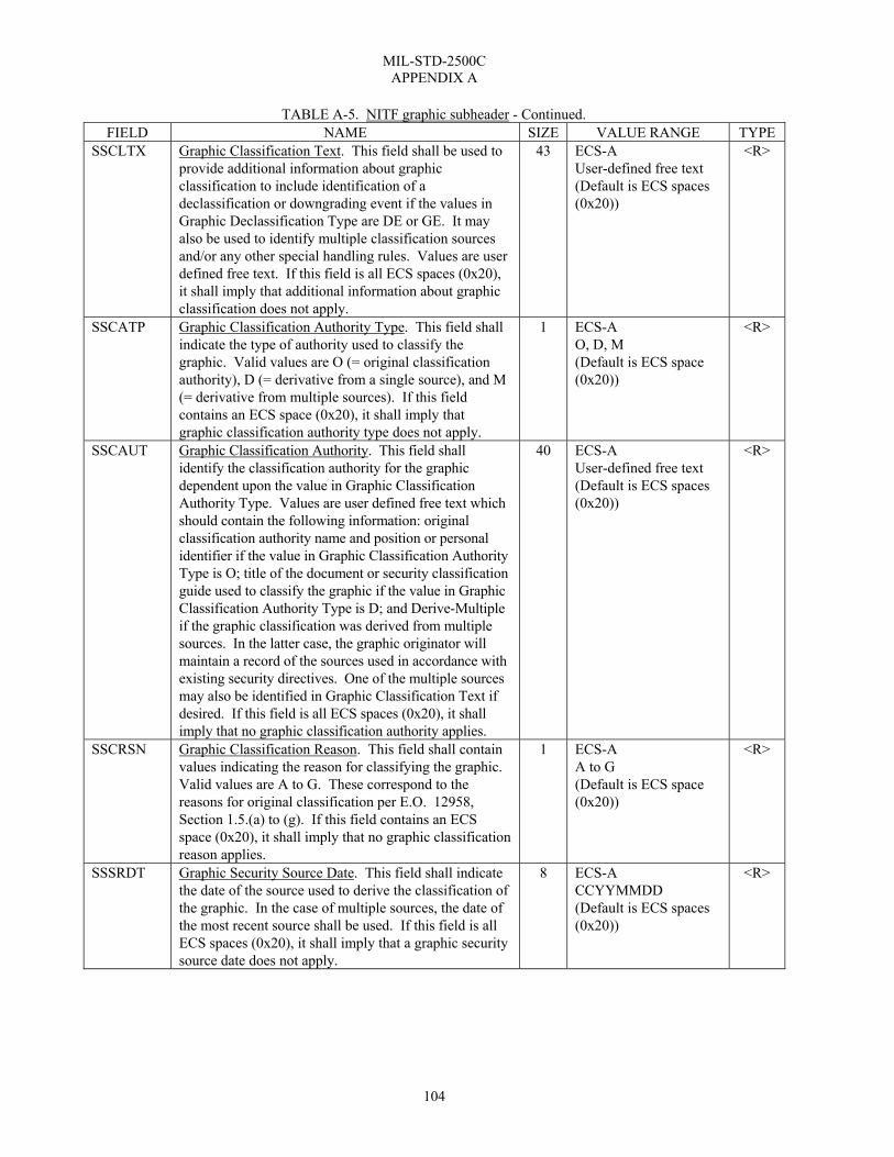
MIL-STD-2500C APPENDIX A
104
TABLE A-5. NITF graphic subheader - Continued. FIELD NAME SIZE VALUE RANGE TYPE
SSCLTX Graphic Classification Text. This field shall be used to provide additional information about graphic classification to include identification of a declassification or downgrading event if the values in Graphic Declassification Type are DE or GE. It may also be used to identify multiple classification sources and/or any other special handling rules. Values are user defined free text. If this field is all ECS spaces (0x20), it shall imply that additional information about graphic classification does not apply.
43 ECS-A User-defined free text (Default is ECS spaces (0x20))
<R>
SSCATP Graphic Classification Authority Type. This field shall indicate the type of authority used to classify the graphic. Valid values are O (= original classification authority), D (= derivative from a single source), and M (= derivative from multiple sources). If this field contains an ECS space (0x20), it shall imply that graphic classification authority type does not apply.
1 ECS-A O, D, M (Default is ECS space (0x20))
<R>
SSCAUT Graphic Classification Authority. This field shall identify the classification authority for the graphic dependent upon the value in Graphic Classification Authority Type. Values are user defined free text which should contain the following information: original classification authority name and position or personal identifier if the value in Graphic Classification Authority Type is O; title of the document or security classification guide used to classify the graphic if the value in Graphic Classification Authority Type is D; and Derive-Multiple if the graphic classification was derived from multiple sources. In the latter case, the graphic originator will maintain a record of the sources used in accordance with existing security directives. One of the multiple sources may also be identified in Graphic Classification Text if desired. If this field is all ECS spaces (0x20), it shall imply that no graphic classification authority applies.
40 ECS-A User-defined free text (Default is ECS spaces (0x20))
<R>
SSCRSN Graphic Classification Reason. This field shall contain values indicating the reason for classifying the graphic. Valid values are A to G. These correspond to the reasons for original classification per E.O. 12958, Section 1.5.(a) to (g). If this field contains an ECS space (0x20), it shall imply that no graphic classification reason applies.
1 ECS-A A to G (Default is ECS space (0x20))
<R>
SSSRDT Graphic Security Source Date. This field shall indicate the date of the source used to derive the classification of the graphic. In the case of multiple sources, the date of the most recent source shall be used. If this field is all ECS spaces (0x20), it shall imply that a graphic security source date does not apply.
8 ECS-A CCYYMMDD (Default is ECS spaces (0x20))
<R>

MIL-STD-2500C APPENDIX A
105
TABLE A-5. NITF graphic subheader - Continued. FIELD NAME SIZE VALUE RANGE TYPE
SSCTLN Graphic Security Control Number. This field shall contain a valid security control number associated with the graphic. The format of the security control number shall be in accordance with the regulations governing the appropriate security channel(s). If this field is all ECS spaces (0x20), it shall imply that no graphic security control number applies.
15 ECS-A (Default is ECS spaces (0x20))
<R>
ENCRYP Encryption. This field shall contain the value BCS zero (0x30) until such time as this specification is updated to define the use of other values.
1 BCS-N positive integer 0=Not Encrypted
R
SFMT Graphic Type. This field shall contain a valid indicator of the representation type of the graphic. The valid value is C, which represents Computer Graphics Metafile. The graphic data contain a Computer Graphics Metafile in binary format that defines the graphic according to MIL-STD-2301A. Future versions of the NITF may include additional CGM profiles.
1 BCS-A C for CGM
R
SSTRUCT Reserved for Future Use. Reserved. 13 BCS-N positive integer 0000000000000 to 9999999999999 (Default is BCS zeros (0x30))
R
SDLVL Graphic Display Level. This field shall contain a valid value that indicates the graphic display level of the graphic relative to other displayed file components in a composite display. The valid values are 001 to 999. The display level of each displayable file component (image or graphic) within a file shall be unique; that is, each number from 001 to 999 is the display level of, at most, one item. The meaning of display level is discussed in paragraph 5.3.3. The graphic or image component in the file having the minimum display level shall have attachment level 0 (ALVL000) (BCS zeros (0x30)).
3 BCS-N positive integer 001 to 999
R
SALVL Graphic Attachment Level. This field shall contain a valid value that indicates the attachment level of the graphic. Valid values for this field are 0 and the display level value of any other image or graphic in the file. The meaning of attachment level is discussed in paragraph 5.3.4. The graphic or image component in the file having the minimum display level shall have attachment level 0 (ALVL000) (BCS zeros (0x30)).
3 BCS-N positive integer 000 to 998 (Default is BCS zeros (0x30))
R

MIL-STD-2500C APPENDIX A
106
TABLE A-5. NITF graphic subheader - Continued. FIELD NAME SIZE VALUE RANGE TYPE
SLOC Graphic Location. The graphics location is specified by providing the location of the graphic’s origin point relative to the position (location of the CCS, image, or graphic to which it is attached. This field shall contain the graphic location offset from the ILOC or SLOC value of the CCS, image, or graphic to which the graphic is attached or from the origin of the CCS when the graphic is unattached (SALVL000). A row and column value of 000 indicates no offset. Positive row and column values indicate offsets down and to the right, while negative row and column values indicate offsets up and to the left.
10 BCS-N RRRRRCCCCC For positive row and column values RRRRR and CCCCC are both in the range 00000 to 99999. For negative row and column values RRRRR and CCCCC are both in the range -0001 to -9999.
R
SBND1 First Graphic Bound Location. This field shall contain an ordered pair of integers defining a location in Cartesian coordinates for use with CGM graphics. It is the upper left corner of the bounding box for the CGM graphic. See paragraph 5.5.2.1 for a description. The format is rrrrrccccc, where rrrrr is the row and ccccc is the column offset from ILOC or SLOC value of the item to which the graphic is attached. If the graphic is unattached (value of the SALVL field is equal to BCS zeros (0x30)), rrrrr and ccccc represent offsets from the origin of the coordinate system that is common to all images and graphics in the file having the value of BCS zeros (0x30) in the SALVL field. The range for rrrrr and ccccc shall be -9999 to 99999.
10 BCS-N rrrrrccccc with -9999≤rrrrr≤99999 -9999≤ccccc≤99999 (Default is BCS zeros (0x30))
R
SCOLOR Graphic Color. If SFMT = C, this field shall contain a C if the CGM contains any color pieces or an M if it is monochrome (i.e., black, white, or levels of grey).
1 BCS-A C, M
R
SBND2 Second Graphic Bound Location. This field shall contain an ordered pair of integers defining a location in Cartesian coordinates for use with CGM graphics. It is the lower right corner of the bounding box for the CGM graphic. See paragraph 5.5.2.1 for a description. The format is rrrrrccccc, where rrrrr is the row and ccccc is the column offset from ILOC or SLOC value of the item to which the graphic is attached. If the graphic is unattached (SALVL field value is BCS zeros(0x30)), rrrrr and ccccc represent offsets from the origin of the coordinate system that is common to all images and graphics in the file having the value of BCS zeros (0x30) in the SALVL field. The range for rrrrr and ccccc shall be -9999 to 99999.
10 BCS-N rrrrrccccc with -9999≤rrrrr≤99999 -9999≤ccccc≤99999 (Default is BCS zeros (0x30))
R
SRES2 Reserved for Future Use. This field is reserved for future use. The default value shall be BCS zeros (0x30).
2 BCS-N positive integer 00 to 99 (Default is BCS zeros (0x30))
R

MIL-STD-2500C APPENDIX A
107
TABLE A-5. NITF graphic subheader - Continued. FIELD NAME SIZE VALUE RANGE TYPE
SXSHDL Graphic Extended Subheader Data Length. A value of BCS zero (0x30) shall represent that no TRE are included in the graphic subheader. If a tagged record extension exists, the field shall contain the sum of the length of all the TRE (paragraph 5.8.1) appearing in the SXSHD field plus 3 bytes (length of SXSOFL field). If a tagged record extension is too long to fit in the SXSHD field, it shall be put in the TRE overflow DES with DESID set to the value TRE_OVERFLOW (paragraph 5.8.3.1).
5 BCS-N positive integer 00000 or 00003 to 09741 (Default is BCS zeros (0x30))
R
SXSOFL Graphic Extended Subheader Overflow. If present, this field shall contain BCS zeros (0x30) if the TRE in SXSHD do not overflow into a DES or shall contain the sequence number of the DES into which they do overflow. This field shall be omitted if the field SXSHDL contains BCS zeros (0x30).
3 BCS-N positive integer 000 to 999
C
SXSHD Graphic Extended Subheader Data. If present, this field shall contain TRE (paragraph 5.8.1) approved and under configuration management by the ISMC. The length of this field shall be the length specified by the field SXSHDL minus 3 bytes. TRE in this field for a graphic shall contain information pertaining specifically to the graphic. TRE shall appear one after the other in this field with no intervening bytes. The first byte of this field shall be the first byte of the first TRE appearing in the field. The last byte of this field shall be the last byte of the last TRE to appear in the field. This field shall be omitted if the field SXSHDL contains BCS zeros (0x30).
†5 TRE(s) C
†5 A value as specified by the SHSHDL field minus 3 (in bytes)
TABLE A-6. NITF text subheader. (TYPE “R” = Required, “C” = Conditional, “< >“ = BCS spaces allowed for entire field)
(“†” annotations are explained at the end of the table) FIELD NAME SIZE VALUE RANGE TYPE
TE File Part Type. This field shall contain the characters “TE” to identify the subheader as a text subheader.
2 BCS-A TE
R
TEXTID Text Identifier. This field shall contain a valid alphanumeric identification code associated with the text item. The valid codes are determined by the application.
7 BCS-A User defined
R
TXTALVL Text Attachment Level. This field shall contain a valid value that indicates the attachment level of the text. Valid values for this field are 000 (BCS zeros (0x30)) or the display level value of any image or graphic in the file.
3 BCS-N positive integer 000 to 998 (Default is BCS zeros (0x30))
R

MIL-STD-2500C APPENDIX A
108
TABLE A-6. NITF text subheader - Continued.
FIELD NAME SIZE VALUE RANGE TYPE TXTDT Text Date and Time. This field shall contain the time
(UTC) (Zulu) of origination of the text in the format CCYYMMDDhhmmss, where CC is the century (00 to 99), YY is the last two digits of the year (00 to 99), MM is the month (01 to 12), DD is the day (01 to 31), hh is the hour (00 to 23), mm is the minute (00 to 59), and ss is the second (00 to 59). UTC (Zulu) is assumed to be the time zone designator to express the time of day. Refer to Paragraph 53.1.7d when a portion of the date and/or time is unknown.
14 BCS-N CCYYMMDDhhmmss
R
TXTITL Text Title. This field shall contain the title of the text item.
80 ECS-A (Default is ECS spaces (0x20))
<R>
TSCLAS Text Security Classification. This field shall contain a valid value representing the classification level of the text. Valid values are T (=Top Secret), S (=Secret), C (=Confidential), R (=Restricted), U (=Unclassified).
1 ECS-A T, S, C, R, or U
R
NOTE: If TSCLAS is T, S, C, or R, then TSCLSY must be populated with a valid code for the security classification system used. TSCLSY Text Security Classification System. This field shall
contain valid values indicating the national or multinational security system used to classify the text. Country Codes per FIPS PUB 10-4 shall be used to indicate national security systems. The designator "XN" is for classified data generated by a component using NATO security system marking guidance. This code is outside the FIPS 10-4 document listing, and was selected to not duplicate that document's existing codes. If this field is all ECS spaces (0x20), it shall imply that no security classification system applies to the text.
2 ECS-A (Default is ECS spaces (0x20))
<R>
NOTE: If any of the following fields are populated with anything other than spaces, then TSCLSY must be populated with a valid code for the security classification system used: TSCODE, TSREL, TSDCTP, TSDCDT, TSDCXM, TSDG, TSDGDT, TSCLTX, TSCATP, TSCAUT, TSCRSN, TSSRDT, and TSCTLN. TSCODE Text Codewords. This field shall contain a valid
indicator of the security compartments associated with the text. Values include one or more of the digraphs found in table A-4. Multiple entries shall be separated by a single ECS spaces (0x20): The selection of a relevant set of codewords is application specific. If this field is all ECS spaces (0x20), it shall imply that no codewords apply to the text.
11 ECS-A (Default is ECS spaces 0x20))
<R>
TSCTLH Text Control and Handling. This field shall contain valid additional security control and/or handling instructions (caveats) associated with the text. Values include digraphs found in table A-4. The digraph may indicate single or multiple caveats. The selection of a relevant caveat(s) is application specific. If this field is all ECS spaces (0x20), it shall imply that no additional control and handling instructions apply to the text.
2 ECS-A (Default is ECS spaces (0x20))
<R>

MIL-STD-2500C APPENDIX A
109
TABLE A-6. NITF text subheader - Continued. FIELD NAME SIZE VALUE RANGE TYPE
TSREL Text Releasing Instructions. This field shall contain a valid list of country and/or multilateral entity codes to which countries and/or multilateral entities the text is authorized for release. Valid items in the list are one or more country codes as found in FIPS PUB 10-4 and/or codes identifying multilateral entities. If this field is all ECS spaces (0x20), it shall imply that no text release instructions apply.
20 ECS-A (Default is ECS spaces (0x20))
<R>
TSDCTP Text Declassification Type. This field shall contain a valid indicator of the type of security declassification or downgrading instructions which apply to the text. Valid values are DD (=declassify on a specific date), DE (=declassify upon occurrence of an event), GD (=downgrade to a specified level on a specific date), GE (=downgrade to a specified level upon occurrence of an event), O (=OADR), and X (= exempt from automatic declassification). If this field is all ECS spaces (0x20), it shall imply that no text security declassification or downgrading instructions apply.
2 ECS-A DD, DE, GD, GE, O, X (Default is ECS spaces (0x20))
<R>
TSDCDT Text Declassification Date. This field shall indicate the date on which a text is to be declassified if the value in Text Declassification Type is DD. If this field is all ECS spaces (0x20), it shall imply that no text declassification date applies.
8 ECS-A CCYYMMDD (Default is ECS spaces (0x20))
<R>
TSDCXM Text Declassification Exemption. This field shall indicate the reason the text is exempt from automatic declassification if the value in Text Declassification Type is X. Valid values are X1 to X8 and X251 to X259. X1 to X8 correspond to the declassification exemptions found in DOD 5200.1-R, paragraphs 4-202b(1) to (8) for material exempt from the 10-year rule. X251 to X259 correspond to the declassification exemptions found in DOD 5200.1-R, paragraphs 4-301a(1) to (9) for permanently valuable material exempt from the 25-year declassification system. If this field is all ECS spaces (0x20), it shall imply that a text declassification exemption does not apply.
4 ECS-A X1 to X8, X251 to X259 (Default is ECS spaces (0x20))
<R>
TSDG Text Downgrade. This field shall indicate the classification level to which a text is to be downgraded if the values in Text Declassification Type are GD or GE. Valid values are S (=Secret), C (=Confidential), R (= Restricted). If this field contains an ECS space (0x20), it shall imply that text security downgrading does not apply.
1 ECS-A S, C, R (Default is ECS space (0x20))
<R>
TSDGDT Text Downgrade Date. This field shall indicate the date on which a text is to be downgraded if the value in Text Declassification Type is GD. If this field is all ECS spaces (0x20), it shall imply that a text security downgrading date does not apply.
8 ECS-A CCYYMMDD (Default is ECS spaces (0x20))
<R>

MIL-STD-2500C APPENDIX A
110
TABLE A-6. NITF text subheader - Continued. FIELD NAME SIZE VALUE RANGE TYPE
TSCLTX Text Classification Text. This field shall be used to provide additional information about text classification to include identification of a declassification or downgrading event if the values in Text Declassification Type are DE or GE.. It may also be used to identify multiple classification sources and/or any other special handling rules. Values are user defined free text. If this field is all ECS spaces (0x20), it shall imply that additional information about text classification does not apply.
43 ECS-A User-defined free text (Default is ECS spaces (0x20))
<R>
TSCATP Text Classification Authority Type. This field shall indicate the type of authority used to classify the text. Valid values are O (= original classification authority), D (= derivative from a single source), and M (= derivative from multiple sources). If this field contains an ECS space (0x20), it shall imply that text classification authority type does not apply.
1 ECS-A O, D, M (Default is ECS space (0x20))
<R>
TSCAUT Text Classification Authority. This field shall identify the classification authority for the text dependent upon the value in Text Classification Authority Type. Values are user defined free text which should contain the following information: original classification authority name and position or personal identifier if the value in Text Classification Authority Type is O; title of the document or security classification guide used to classify the text if the value in Text Classification Authority Type is D; and Derive-Multiple if the text classification was derived from multiple sources. In the latter case, the text originator will maintain a record of the sources used in accordance with existing security directives. One of the multiple sources may also be identified in Text Classification Text if desired. If this field is all ECS spaces (0x20), it shall imply that no text classification authority applies.
40 ECS-A User-defined free text (Default is ECS spaces (0x20))
<R>
TSCRSN Text Classification Reason. This field shall contain values indicating the reason for classifying the text. Valid values are A to G. These correspond to the reasons for original classification per E.O. 12958, Section 1.5.(a) to (g). If this field contains an ECS space (0x20), it shall imply that no text classification reason applies.
1 ECS-A A to G (Default is ECS space (0x20))
<R>
TSSRDT Text Security Source Date. This field shall indicate the date of the source used to derive the classification of the text. In the case of multiple sources, the date of the most recent source shall be used. If this field is all ECS spaces (0x20), it shall imply that a text security source date does not apply.
8 ECS-A CCYYMMDD (Default is ECS spaces (0x20))
<R>

MIL-STD-2500C APPENDIX A
111
TABLE A-6. NITF text subheader - Continued. FIELD NAME SIZE VALUE RANGE TYPE
TSCTLN Text Security Control Number. This field shall contain a valid security control number associated with the text. The format of the security control number shall be in accordance with the regulations governing the appropriate security channel(s). If this field is all ECS spaces (0x20), it shall imply that no text security control number applies.
15 ECS-A (Default is ECS spaces (0x20))
<R>
ENCRYP Encryption. This field shall contain the value BCS zero (0x30) until such time as this specification is updated to define the use of other values.
1 BCS-N positive integer (Default is BCS zero (0x30)) 0=Not Encrypted
R
TXTFMT Text Format. This field shall contain a valid three-character code indicating the format or type of text data. Valid codes are MTF to indicate USMTF (Refer to MIL-STD-6040 for examples of the USMTF format), STA to indicate BCS, UT1 to indicate ECS text formatting, and U8S to indicate U8S text formatting. Refer to paragraph 5.7.1 for additional discussion of standards and the BCS.
3 BCS-A MTF, STA, UT1, U8S
R
TXSHDL Text Extended Subheader Data Length. A value of BCS zeros (0x30) shall represent that no TRE are included in the text subheader. If a TRE exists, the field shall contain the sum of the length of all the TRE (paragraph 5.8.1) appearing in the TSXHD field plus 3 bytes (length of TSXOFL field). If a TRE is too long to fit in the TXSHD field, it shall be put in the TRE overflow DES with DESID set to the value TRE_OVERFLOW (paragraph 5.8.3.1).
5 BCS-N positive integer 00000 or 00003 to 09717 (Default is BCS zero (0x30))
R
TXSOFL Text Extended Subheader Overflow. If present, this field shall contain BCS zeros (0x30) if TRE in TXSHD do not overflow into a DES, or shall contain the sequence number in the file of the DES into which they do overflow. This field shall be omitted if the field TXSHDL contains BCS zeros (0x30).
3 BCS-N positive integer 000 to 999
C
TXSHD Text Extended Subheader Data. If present, this field shall contain TRE (paragraph 5.8.1) approved and under configuration management by the ISMC. The length of this field shall be the length specified by the field TXSHDL minus 3. TRE in this field shall contain information pertaining specifically to the text. TRE shall appear one after the other in this field with no intervening bytes. The first byte of this field shall be the first byte of the first TRE appearing in the field. The last byte of this field shall be the last byte of the last TRE to appear in the field. This field shall be omitted if the field TXSHDL contains BCS zeros (0x30).
†6 BCS-A C
†6 A value as specified by the value in the TXSHDL field minus 3 (in bytes).

MIL-STD-2500C APPENDIX A
112
TABLE A-7. Registered and controlled tagged record extension format. (TYPE “R” = Required, “C” = Conditional, “< >“ = BCS spaces allowed for entire field)
(“†” annotations are explained at the end of the table) FIELD NAME SIZE VALUE RANGE TYPE RETAG or CETAG
Unique Extension Type Identifier. This field shall contain a valid alphanumeric identifier properly registered with the ISMC.
6 BCS-A R
REL or CEL
Length of REDATA Field. This field shall contain the length in bytes of the data contained in REDATA or CEDATA. The TRE length is 11 plus the size of the REL field or the CEL field.
5 BCS-N positive integer 00001 to 99985
R
REDATA or CEDATA where appropriate
User-Defined Data. This field shall contain data of either binary or character data types defined by and formatted according to user specification. The length of this field shall not cause any other NITF field length limits to be exceeded, but is otherwise fully user-defined.
†7 User-defined R
†7 A value as indicated in the REL field or the CEL field (in bytes).
TABLE A-8. NITF Data Extension Segment (DES) subheader. (TYPE “R” = Required, “C” = Conditional, “< >“ = BCS spaces allowed for entire field)
(“†” annotations are explained at the end of the table) FIELD NAME SIZE VALUE RANGE TYPE
DE File Part Type. This field shall contain the characters “DE” to identify the subheader as a data extension.
2 BCS-A DE
R
DESID Unique DES Type Identifier. This field shall contain a valid alphanumeric identifier properly registered with the ISMC.
25 BCS-A Registered value only
R
DESVER Version of the Data Definition. This field shall contain the alphanumeric version number of the use of the tag. The version number is assigned as part of the registration process.
2 BCS-N positive integer 01 to 99
R
DECLAS Data Extension File Security Classification. This field shall contain a valid value representing the classification level of the DES. Valid values are T for Top Secret, S for Secret, C for Confidential, R for Restricted, or U for Unclassified.
1 ECS-A T, S, C, R, or U
R
NOTE: If the value of the DESCLAS field is T, S, C, or R, then the DESCLSY field must be populated with a valid code for the security classification system used. DESCLSY DES Security Classification System. This field shall
contain valid values indicating the national or multinational security system used to classify the DES. Country Codes per FIPS PUB 10-4 are used to indicate national security systems. The designator "XN" is for classified data generated by a component using NATO security system marking guidance. This code is outside the FIPS 10-4 document listing, and was selected to not duplicate that document's existing codes. If this field is all ECS spaces (0x20), it shall imply that no Security Classification System applies to the DES.
2 ECS-A (Default is ECS spaces (0x20))
<R>
NOTE: If any of the following fields are populated with anything other than spaces, then the DESCLSY field must be populated with a valid code for the security classification system used: DESCODE, DESREL, DESDCTP, DESDCDT, DESDCXM, DESDG, DESDGDT, DESCLDES, DESCATP, DESCAUT, DESCRSN, DESSRDT, and DESCTLN.

MIL-STD-2500C APPENDIX A
113
TABLE A-8. NITF Data Extension Segment (DES) subheader - Continued.
FIELD NAME SIZE VALUE RANGE TYPE DESCODE DES Codewords. This field shall contain a valid
indicator of the security compartments associated with the DES. Values include one or more of the digraphs found in table A-4. Multiple entries shall be separated by a single ECS space (0x20). The selection of a relevant set of codewords is application specific. If this field is all ECS spaces (0x20), it shall imply that no codewords apply to the DES.
11 ECS-A (Default is ECS spaces (0x20))
<R>
DESCTLH DES Control and Handling. This field shall contain valid additional security control and/or handling instructions (caveats) associated with the DES. Values include digraphs found in table A-4. The digraph may indicate single or multiple caveats. The selection of a relevant caveat(s) is application specific. If this field is all ECS spaces (0x20), it shall imply that no additional control and handling instructions apply to the DES.
2 ECS-A (Default is ECS spaces (0x20))
<R>
DESREL DES Releasing Instructions. This field shall contain a valid list of countries to which the DES is authorized for release. Typical values include one or more country codes as found in FIPS PUB 10-4 separated by a single BCS space (0x20). If this field is all ECS spaces (0x20), it shall imply that no DES release instructions apply.
20 ECS-A (Default is ECS spaces (0x20))
<R>
DESDCTP DES Declassification Type. This field shall contain a valid indicator of the type of security declassification or downgrading instructions which apply to the DES. Valid values are DD for declassify on a specific date, DE for declassify upon occurrence of an event, GD for downgrade to a specified level on a specific date, GE for downgrade to a specified level upon occurrence of an event, O for OADR, and X for exempt from automatic declassification. If this field is all ECS spaces (0x20), it shall imply that no DES security declassification or downgrading instructions apply.
2 ECS-A DD, DE, GD, GE, O, X (Default is ECS spaces (0x20))
<R>
DESDCDT DES Declassification Date. This field shall indicate the date on which a DES is to be declassified if the value in DESDCTP is DD. If this field is all ECS spaces (0x20), it shall imply that no DES declassification date applies.
8 ECS-A CCYYMMDD (Default is ECS spaces (0x20))
<R>
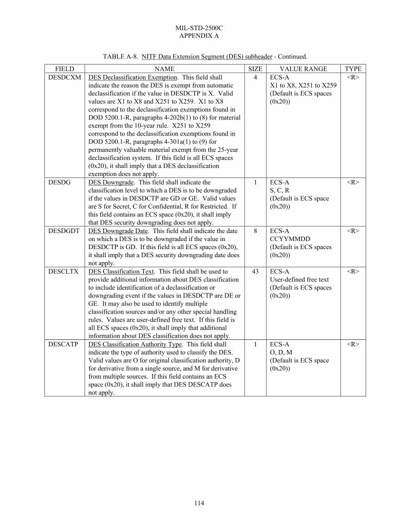
MIL-STD-2500C APPENDIX A
114
TABLE A-8. NITF Data Extension Segment (DES) subheader - Continued.
FIELD NAME SIZE VALUE RANGE TYPE DESDCXM DES Declassification Exemption. This field shall
indicate the reason the DES is exempt from automatic declassification if the value in DESDCTP is X. Valid values are X1 to X8 and X251 to X259. X1 to X8 correspond to the declassification exemptions found in DOD 5200.1-R, paragraphs 4-202b(1) to (8) for material exempt from the 10-year rule. X251 to X259 correspond to the declassification exemptions found in DOD 5200.1-R, paragraphs 4-301a(1) to (9) for permanently valuable material exempt from the 25-year declassification system. If this field is all ECS spaces (0x20), it shall imply that a DES declassification exemption does not apply.
4 ECS-A X1 to X8, X251 to X259 (Default is ECS spaces (0x20))
<R>
DESDG DES Downgrade. This field shall indicate the classification level to which a DES is to be downgraded if the values in DESDCTP are GD or GE. Valid values are S for Secret, C for Confidential, R for Restricted. If this field contains an ECS space (0x20), it shall imply that DES security downgrading does not apply.
1 ECS-A S, C, R (Default is ECS space (0x20))
<R>
DESDGDT DES Downgrade Date. This field shall indicate the date on which a DES is to be downgraded if the value in DESDCTP is GD. If this field is all ECS spaces (0x20), it shall imply that a DES security downgrading date does not apply.
8 ECS-A CCYYMMDD (Default is ECS spaces (0x20))
<R>
DESCLTX DES Classification Text. This field shall be used to provide additional information about DES classification to include identification of a declassification or downgrading event if the values in DESDCTP are DE or GE. It may also be used to identify multiple classification sources and/or any other special handling rules. Values are user-defined free text. If this field is all ECS spaces (0x20), it shall imply that additional information about DES classification does not apply.
43 ECS-A User-defined free text (Default is ECS spaces (0x20))
<R>
DESCATP DES Classification Authority Type. This field shall indicate the type of authority used to classify the DES. Valid values are O for original classification authority, D for derivative from a single source, and M for derivative from multiple sources. If this field contains an ECS space (0x20), it shall imply that DES DESCATP does not apply.
1 ECS-A O, D, M (Default is ECS space (0x20))
<R>

MIL-STD-2500C APPENDIX A
115
TABLE A-8. NITF Data Extension Segment (DES) subheader - Continued.
FIELD NAME SIZE VALUE RANGE TYPE DESCAUT DES Classification Authority. This field shall identify
the classification authority for the DES dependent upon the value in DESCATP. Values are user-defined free text which should contain the following information: original classification authority name and position or personal ID if the value in DESCATP is O; title of the document or security classification guide used to classify the DES if the value in DESCATP is D; and Deriv- Multiple if the DES classification was derived from multiple sources. In the latter case, the DES originator will maintain a record of the sources used in accordance with existing security directives. One of the multiple sources may also be identified in DESCLTX if desired. If this field is all ECS spaces (0x20), it shall imply that no DES file classification authority applies.
40 ECS-A User-defined free text (Default is ECS spaces (0x20))
<R>
DESCRSN DES Classification Reason. This field shall contain a value indicating the reason for classifying the DES. Valid values are A to G. These correspond to the reasons for original classification per E.O. 12958, Section 1.5.(a) to(g). If this field contains an ECS spaces (0x20), it shall imply that no DES classification reason applies.
1 ECS-A A to G (Default is ECS space (0x20))
<R>
DESSRDT DES Security Source Date. This field shall indicate the date of the source used to derive the classification of the DES. In the case of multiple sources, the date of the most recent source shall be used. If this field is all ECS spaces (0x20), it shall imply that a DES security source date does not apply.
8 ECS-A CCYYMMDD (Default is ECS spaces (0x20))
<R>
DESCTLN DES Security Control Number. This field shall contain a valid security control number associated with the DES. The format of the security control number shall be in accordance with the regulations governing the appropriate security channel(s). If this field is all ECS spaces (0x20), it shall imply that no DES security control number applies.
15 ECS-A (Default is ECS spaces (0x20))
<R>
DESOFLW DES Overflowed Header Type. This field shall be present if DESID = TRE_OVERFLOW. Its presence indicates that the DES contains a TRE that would not fit in the file header or segment subheader where it would ordinarily be located. Its value indicates the segment type to which the enclosed TRE is relevant.
6 BCS-A XHD, IXSHD, SXSHD, TXSHD, UDHD, UDID
C
DESITEM DES Data Item Overflowed. This field shall be present if DESOFLW is present. It shall contain the number of the data item in the file, of the type indicated in DESOFLW to which the TRE in the segment apply. For example, if DESOFLW = UDID and DESITEM = 003, then the TRE in the segment apply to the third image in the file. If the value of DESOFLW = UDHD, the value of DESITEM shall be BCS zeros (0x30).
3 BCS-N positive integer 000 to 999
C

MIL-STD-2500C APPENDIX A
116
TABLE A-8. NITF Data Extension Segment (DES) subheader - Continued.
FIELD NAME SIZE VALUE RANGE TYPE DESSHL DES User-defined Subheader Length. This field shall
contain the number of bytes in the field DESSHF. If this field contains BCS zeros (0x30), DESSHF shall not appear in the DES subheader. This field shall contain BCS zeros (0x30) if DESID = “Registered Extensions” or “Controlled Extensions.”
4 BCS-N positive integer 0000 to 9999
R
DESSHF DES User-defined Subheader Fields. This field shall contain user-defined fields. Data in this field shall be alphanumeric, formatted according to user specification.
†8 BCS-A User defined
C
DESDATA DES User-Defined Data. This field shall contain data of either binary or character types defined by and formatted according to the user’s specification. However, if DESID=TRE_OVERFLOW, the TRE shall appear according to their definition with no intervening bytes. The length of this field shall not cause another NITF field length limits to be exceeded, but is otherwise fully user-defined.
††8 User defined R
†8 Value of the DESSHL (in bytes) ††8 Determined by user. If the DESID is set to the value TRE_OVERFLOW, this signifies the sum of the lengths of the included TRE.
TABLE A-8(A). Tagged Record Extension Overflow (TRE_OVERFLOW) Data Extension Segment (DES) subheader.
TYPE R = Required, C = Conditional, < > = BCS spaces (code 0x20) are allowed for the entire field († annotations are explained at the end of the table)
FIELD NAME SIZE VALUE RANGE TYPE DE Data Extension Subheader. This field shall contain
the characters DE to identify the subheader as a data extension.
2 BCS-A DE
R
DESID Unique DES Type Identifier. This field shall contain TRE_OVERFLOW
25 BCS-A TRE_OVERFLOW
R
DESVER Version of the Data Definition. This field shall contain the alphanumeric version number of the use of the Tag. The version number is assigned as part of the registration process.
2 BCS-N positive integer 01
R
DECLAS Data Extension File Security Classification. This field shall contain a valid value representing the classification level of the DES. Valid values are T for Top Secret, S for Secret, C for Confidential, R for Restricted, or U for Unclassified.
1 ECS-A T, S, C, R, or U
R
NOTE: If the value of the DESCLAS field is T, S, C, or R, then the DESCLSY field must be populated with a valid code for the security classification system used.

MIL-STD-2500C APPENDIX A
117
TABLE A-8(A). Tagged Record Extension Overflow (TRE-OVERFLOW)
Data Extension Segment (DES) subheader - Continued. FIELD NAME SIZE VALUE RANGE TYPE
DESCLSY DES Security Classification System. This field shall contain valid values indicating the national or multinational security system used to classify the DES. Country Codes per FIPS PUB 10-4 are used to indicate national security systems. The designator "XN" is for classified data generated by a component using NATO security system marking guidance. This code is outside the FIPS 10-4 document listing, and was selected to not duplicate that document's existing codes. If this field is all ECS spaces (code 0x20), it shall imply that no Security Classification System applies to the DES.
2 ECS-A (Default is ECS spaces (0x20))
<R>
NOTE: If any of the following fields are populated with anything other than spaces, then the DESCLSY field must be populated with a valid code for the security classification system used: DESCODE, DESREL, DESDCTP, DESDCDT, DESDCXM, DESDG, DESDGDT, DESCLDES, DESCATP, DESCAUT, DESCRSN, DESSRDT, and DESCTLN. DESCODE DES Codewords. This field shall contain a valid
indicator of the security compartments associated with the DES. Values include one or more of the digraphs found in table A-4. Multiple entries shall be separated by a single ECS space (0x20). The selection of a relevant set of codewords is application specific. If this field is all ECS spaces (0x20), it shall imply that no codewords apply to the DES.
11 ECS-A (Default is ECS spaces (0x20))
<R>
DESCTLH DES Control and Handling. This field shall contain valid additional security control and/or handling instructions (caveats) associated with the DES. Values include digraphs found in table A-4. The digraph may indicate single or multiple caveats. The selection of a relevant caveat(s) is application specific. If this field is all ECS spaces (0x20), it shall imply that no additional control and handling instructions apply to the DES.
2 ECS-A (Default is ECS spaces (0x20))
<R>
DESREL DES Releasing Instructions. This field shall contain a valid list of countries to which the DES is authorized for release. Typical values include one or more country codes as found in FIPS PUB 10-4 separated by a single BCS space (0x20). If this field is all ECS spaces (0x20), it shall imply that no DES release instructions apply.
20 ECS-A (Default is ECS spaces (0x20))
<R>

MIL-STD-2500C APPENDIX A
118
TABLE A-8(A). Tagged Record Extension Overflow (TRE-OVERFLOW) Data Extension Segment (DES) subheader - Continued.
FIELD NAME SIZE VALUE RANGE TYPE DESDCTP DES Declassification Type. This field shall contain a
valid indicator of the type of security declassification or downgrading instructions which apply to the DES. Valid values are DD for declassify on a specific date, DE for declassify upon occurrence of an event, GD for downgrade to a specified level on a specific date, GE for downgrade to a specified level upon occurrence of an event, O for OADR, and X for exempt from automatic declassification. If this field is all ECS spaces (code 0x20), it shall imply that no DES security declassification or downgrading instructions apply.
2 ECS-A DD, DE, GD, GE, O, X (Default is ECS spaces (0x20))
<R>
DESDCDT DES Declassification Date. This field shall indicate the date on which a DES is to be declassified if the value of the DESDCTP field is DD. If this field is all ECS spaces (code 0x20), it shall imply that no DES declassification date applies.
8 ECS-A CCYYMMDD (Default is ECS spaces (0x20))
<R>
DESDCXM DES Declassification Exemption. This field shall indicate the reason the DES is exempt from automatic declassification if the value of the DESDCTP field is X. Valid values are X1 to X8 and X251 to X259. X1 to X8 correspond to the declassification exemptions found in DOD 5200.1-R, paragraphs 4-202b(1) to (8) for material exempt from the 10-year rule. X251 to X259 correspond to the declassification exemptions found in DOD 5200.1-R, paragraphs 4-301a(1) to (9) for permanently valuable material exempt from the 25-year declassification system. If this field is all ECS spaces (code 0x20), it shall imply that a DES declassification exemption does not apply.
4 ECS-A X1 to X8 X251 to X259 (Default is ECS spaces (0x20))
<R>
DESDG DES Downgrade. This field shall indicate the classification level to which a DES is to be downgraded if the value of the DESDCTP field is GD or GE. Valid values are S for Secret, C for Confidential, R for Restricted. If this field contains an ECS space (code 0x20), it shall imply that DES security downgrading does not apply.
1 ECS-A S, C, R (Default is ECS space (0x20))
<R>
DESDGDT DES Downgrade Date. This field shall indicate the date on which a DES is to be downgraded if the value of the DESDCTP field is GD. If this field is all ECS spaces (code 0x20), it shall imply that a DES security downgrading date does not apply.
8 ECS-A CCYYMMDD (Default is ECS spaces (0x20))
<R>

MIL-STD-2500C APPENDIX A
119
TABLE A-8(A). Tagged Record Extension Overflow (TRE-OVERFLOW) Data Extension Segment (DES) subheader - Continued.
FIELD NAME SIZE VALUE RANGE TYPE DESCLTX DES Classification Text. This field shall be used to
provide additional information about DES classification to include identification of a declassification or downgrading event if the value of the DESDCTP field is DE or GE. It may also be used to identify multiple classification sources and/or any other special handling rules. Values are user-defined free text. If this field is all ECS spaces (code 0x20), it shall imply that additional information about DES classification does not apply.
43 ECS-A User-defined free text (Default is ECS spaces (0x20))
<R>
DESCATP DES Classification Authority Type. This field shall indicate the type of authority used to classify the DES. Valid values are O for original classification authority, D for derivative from a single source, and M for derivative from multiple sources. If this field contains an ECS space (code 0x20), it shall imply that DES classification authority type does not apply.
1 ECS-A O, D, M (Default is ECS space (0x20))
<R>
DESCAUT DES Classification Authority. This field shall identify the classification authority for the DES dependent upon the value of the DESCATP field. Values are user-defined free text which should contain the following information: original classification authority name and position or personal ID if the of the DESCATP field is O; title of the document or security classification guide used to classify the DES if the of the DESCATP field is D; and Deriv-Multiple if the DES classification was derived from multiple sources and the value of the DESCATP field is M. In the latter case, the DES originator will maintain a record of the sources used in accordance with existing security directives. One of the multiple sources may also be identified by the DESCLTX field if desired. If this field is all ECS spaces (code 0x20), it shall imply that no DES classification authority applies.
40 ECS-A User-defined free text (Default is ECS spaces (0x20))
<R>
DESCRSN DES Classification Reason. This field shall contain values indicating the reason for classifying the DES. Valid values are A to G. These correspond to the reasons for original classification per E.O. 12958, Section 1.5.(a) to (g). If this field contains an ECS spaces (code 0x20), it shall imply that no DES classification reason applies.
1 ECS-A A to G (Default is ECS space (0x20))
<R>
DESSRDT DES Security Source Date. This field shall indicate the date of the source used to derive the classification of the DES. In the case of multiple sources, the date of the most recent source shall be used. If this field is all ECS spaces (code 0x20), it shall imply that a DES security source date does not apply.
8 ECS-A CCYYMMDD (Default is ECS spaces (0x20))
<R>

MIL-STD-2500C APPENDIX A
120
TABLE A-8(A). Tagged Record Extension Overflow (TRE-OVERFLOW) Data Extension Segment (DES) subheader - Continued.
FIELD NAME SIZE VALUE RANGE TYPE DESCTLN DES Security Control Number. This field shall
contain a valid security control number associated with the DES. The format of the security control number shall be in accordance with the regulations governing the appropriate security channel(s). If this field is all ECS spaces (code 0x20), it shall imply that no DES security control number applies.
15 ECS-A (Default is ECS spaces (0x20))
<R>
DESOFLW Overflowed Header Type. This field shall be present if DESID contains TRE_OVERFLOW. Its presence indicates that the DES contains a TRE that would not fit in the NITF file header or segment subheader where it would ordinarily be located. Its value indicates the data type to which the enclosed TRE is relevant.
6 BCS-A UDHD, UDID, XHD, IXSHD, SXSHD, TXSHD; otherwise, field is omitted.
C
DESITEM Data Item Overflowed. This field shall be present if the DESOFLW field is present. It shall contain the number of the data item in the NITF file, of the type indicated in the DESOFLW field to which the TRE in the segment apply. If the value of the DESOFLW field is UDHD or XHD the value of the DESITEM field shall be 000.
3 BCS-N positive integer 000 to 999
C
DESSHL Length of DES-Defined Subheader Fields. 4 BCS-N positive integer 0000
R
DESDATA DES-Defined Data Field. This field shall contain data of either binary or character types defined by and formatted according to the user's specification. The length of this field shall not cause any other NITF field length limits to be exceeded, but is otherwise fully user-defined.
† User-defined TRE with no intervening octets.
R
† Profile defined.
TABLE A-8(B). Streaming File Header (STREAMING_FILE_HEADER) Data Extension Segment (DES) subheader.
TYPE R = Required, C = Conditional, < > = BCS spaces (code 0x20) are allowed for the entire field († annotations are explained at the end of the table)
FIELD NAME SIZE VALUE RANGE TYPE DE Data Extension Subheader. This field shall contain the
characters DE to identify the subheader as a data extension.
2 BCS-A DE
R
DESID Unique DES Type Identifier. This field shall contain STREAMING_FILE_HEADER.
25 BCS-A STREAMING_FILE_HEADER
R
DESVER Version of the Data Definition. This field shall contain the alphanumeric version number of the use of the Tag. The version number is assigned as part of the registration process.
2 BCS-N positive integer 01
R

MIL-STD-2500C APPENDIX A
121
TABLE A-8(B). Streaming File Header (STREAMING-FILE-HEADER) Data Extension Segment (DES) subheader – Continued.
FIELD NAME SIZE VALUE RANGE TYPE DECLAS Data Extension File Security Classification. This field
shall contain a valid value representing the classification level of the DES. Valid values are T for Top Secret, S for Secret, C for Confidential, R for Restricted, or U for Unclassified.
1 ECS-A T, S, C, R, or U
R
NOTE: If the value of the DESCLAS field is T, S, C, or R, then the DESCLSY field must be populated with a valid code for the security classification system used. DESCLSY DES Security Classification System. This field shall
contain valid values indicating the national or multinational security system used to classify the DES. Country Codes per FIPS PUB 10-4 are used to indicate national security systems. The designator "XN" is for classified data generated by a component using NATO security system marking guidance. This code is outside the FIPS 10-4 document listing, and was selected to not duplicate that document's existing codes. If this field is all ECS spaces (code 0x20), it shall imply that no Security Classification System applies to the DES.
2 ECS-A (Default is ECS spaces (0x20))
<R>
NOTE: If any of the following fields are populated with anything other than spaces, then the DESCLSY field must be populated with a valid code for the security classification system used: DESCODE, DESREL, DESDCTP, DESDCDT, DESDCXM, DESDG, DESDGDT, DESCLDES, DESCATP, DESCAUT, DESCRSN, DESSRDT, and DESCTLN. DESCODE DES Codewords. This field shall contain a valid
indicator of the security compartments associated with the DES. Values include one or more of the digraphs found in table A-4. Multiple entries shall be separated by a single ECS space (0x20). The selection of a relevant set of codewords is application specific. If this field is all ECS spaces (0x20), it shall imply that no codewords apply to the DES.
11 ECS-A (Default is ECS spaces (0x20))
<R>
DESCTLH DES Control and Handling. This field shall contain valid additional security control and/or handling instructions (caveats) associated with the DES. Values include digraphs found in table A-4. The digraph may indicate single or multiple caveats. The selection of a relevant caveat(s) is application specific. If this field is all ECS spaces (0x20), it shall imply that no additional control and handling instructions apply to the DES.
2 ECS-A (Default is ECS spaces (0x20))
<R>
DESREL DES Releasing Instructions. This field shall contain a valid list of countries to which the DES is authorized for release. Typical values include one or more country codes as found in FIPS PUB 10-4 separated by a single BCS space (0x20). If this field is all ECS spaces (0x20), it shall imply that no DES release instructions apply.
20 ECS-A (Default is ECS spaces (0x20))
<R>

MIL-STD-2500C APPENDIX A
122
TABLE A-8(B). Streaming File Header (STREAMING-FILE-HEADER) Data Extension Segment (DES) subheader – Continued.
FIELD NAME SIZE VALUE RANGE TYPE DESDCTP DES Declassification Type. This field shall contain a
valid indicator of the type of security declassification or downgrading instructions which apply to the DES. Valid values are DD for declassify on a specific date, DE for declassify upon occurrence of an event, GD for downgrade to a specified level on a specific date, GE for downgrade to a specified level upon occurrence of an event, O for OADR, and X for exempt from automatic declassification. If this field is all ECS spaces (code 0x20), it shall imply that no DES security declassification or downgrading instructions apply.
2 ECS-A DD, DE, GD, GE, O, X (Default is ECS spaces (0x20))
<R>
DESDCDT DES Declassification Date. This field shall indicate the date on which a DES is to be declassified if the value of the DESDCTP field is DD. If this field is all ECS spaces (code 0x20), it shall imply that no DES declassification date applies.
8 ECS-A CCYYMMDD (Default is ECS spaces (0x20))
<R>
DESDCXM DES Declassification Exemption. This field shall indicate the reason the DES is exempt from automatic declassification if the value of the DESDCTP field is X. Valid values are X1 to X8 and X251 to X259. X1 to X8 correspond to the declassification exemptions found in DOD 5200.1-R, paragraphs 4-202b(1) to (8) for material exempt from the 10-year rule. X251 to X259 correspond to the declassification exemptions found in DOD 5200.1-R, paragraphs 4-301a(1) to (9) for permanently valuable material exempt from the 25- year declassification system. If this field is all ECS spaces (code 0x20), it shall imply that a DES declassification exemption does not apply.
4 ECS-A X1 to X8 X251 to X259 (Default is ECS spaces (0x20))
<R>
DESDG DES Downgrade. This field shall indicate the classification level to which a DES is to be downgraded if the value of the DESDCTP field is GD or GE. Valid values are S for Secret, C for Confidential, R for Restricted. If this field contains an ECS space (code 0x20), it shall imply that DES security downgrading does not apply.
1 ECS-A S, C, R (Default is ECS space (0x20))
<R>
DESDGDT DES Downgrade Date. This field shall indicate the date on which a DES is to be downgraded if the value of the DESDCTP field is GD. If this field is all ECS spaces (code 0x20), it shall imply that a DES security downgrading date does not apply.
8 ECS-A CCYYMMDD (Default is ECS spaces (0x20))
<R>

MIL-STD-2500C APPENDIX A
123
TABLE A-8(B). Streaming File Header (STREAMING-FILE-HEADER) Data Extension Segment (DES) subheader – Continued.
FIELD NAME SIZE VALUE RANGE TYPE DESCLTX DES Classification Text. This field shall be used to
provide additional information about DES classification to include identification of a declassification or downgrading event if the value of the DESDCTP field is DE or GE. It may also be used to identify multiple classification sources and/or any other special handling rules. Values are user-defined free text. If this field is all ECS spaces (code 0x20), it shall imply that additional information about DES classification does not apply.
43 ECS-A User-defined free text (Default is ECS spaces (0x20))
<R>
DESCATP DES Classification Authority Type. This field shall indicate the type of authority used to classify the DES. Valid values are O for original classification authority, D for derivative from a single source, and M for derivative from multiple sources. If this field contains an ECS space (code 0x20), it shall imply that DES classification authority type does not apply.
1 ECS-A O, D, M (Default is ECS space (0x20))
<R>
DESCAUT DES Classification Authority. This field shall identify the classification authority for the DES dependent upon the value of the DESCATP field. Values are user-defined free text which should contain the following information: original classification authority name and position or personal ID if the of the DESCATP field is O; title of the document or security classification guide used to classify the DES if the of the DESCATP field is D; and Deriv-Multiple if the DES classification was derived from multiple sources and the value of the DESCATP field is M. In the latter case, the DES originator will maintain a record of the sources used in accordance with existing security directives. One of the multiple sources may also be identified by the DESCLTX field if desired. If this field is all ECS spaces (code 0x20), it shall imply that no DES Classification authority applies.
40 ECS-A User-defined free text (Default is ECS spaces (0x20))
<R>
DESCRSN DES Classification Reason. This field shall contain values indicating the reason for classifying the DES. Valid values are A to G. These correspond to the reasons for original classification per E.O. 12958, Section 1.5.(a) to (g). If this field contains an ECS spaces (code 0x20), it shall imply that no DES classification reason applies.
1 ECS-A A to G (Default is ECS space (0x20))
<R>
DESSRDT DES Security Source Date. This field shall indicate the date of the source used to derive the classification of the DES. In the case of multiple sources, the date of the most recent source shall be used. If this field is all ECS spaces (code 0x20), it shall imply that a DES security source date does not apply.
8 ECS-A CCYYMMDD (Default is ECS spaces (0x20))
<R>

MIL-STD-2500C APPENDIX A
124
TABLE A-8(B). Streaming File Header (STREAMING-FILE-HEADER) Data Extension Segment (DES) subheader – Continued.
FIELD NAME SIZE VALUE RANGE TYPE DESCTLN DES Security Control Number. This field shall contain
a valid security control number associated with the DES. The format of the security control number shall be in accordance with the regulations governing the appropriate security channel(s). If this field is all ECS spaces (code 0x20), it shall imply that no DES security control number applies.
15 ECS-A (Default is ECS spaces (0x20))
<R>
DESSHL Length of DES-Defined Subheader Fields. 4 BCS-N positive integer 0000
R
SFH_L1 SFH Length 1. This field shall contain the number of bytes in the SFH_DR field.
7 BCS-N positive integer 0 to 9999999
R
SFH_DELIM1 SFH Delimiter 1. This field shall contain the hexadecimal value 0x0A6E1D97. It provides a unique value that can be identified as the beginning of the replacement data.
4 BCS-A 0x0A6E1D97
R
SFH_DR Replacement Data. This field shall contain the replacement bytes for the NITF file header beginning with the FHDR field and continuing for the number of bytes indicated in the SFH_L1 or SFH_L2 field. The NITF file header replication shall at least continue through all the NITF file header fields that are marked incomplete.
† R
SFH_DELIM2 SFH Delimiter 2. This field shall contain the hexadecimal value 0x0ECA14BF. It provides a unique value that can be identified as the end of the replacement data.
4 BCS-A 0x0ECA14BF
R
SFH_L2 SFH Length 2. A repeat of SFH-L1, this field shall contain the number of bytes in the SFHDR field.
7 BCS-N positive integer 0 to 9999999
R
† As specified in SFH_L1 and SFH_L2.
TABLE A-9. NITF Reserved Extension Segment (RES) subheader. (TYPE “R” = Required, “C” = Conditional, “< >“ = BCS spaces allowed for entire field)
(“†” annotations are explained at the end of the table) FIELD NAME SIZE VALUE RANGE TYPE
RE File Part Type. This field shall contain the characters “RE” to identify the subheader as a reserved extension.
2 BCS-A RE
R
RESID Unique RES Type Identifier. This field shall contain a valid alphanumeric identifier properly registered with the ISMC.
25 BCS-A Registered value only
R
RESVER Version of the Data Definition. This field shall contain the alphanumeric version number of the use of the tag. The version number is assigned as part of the registration process.
2 BCS-N positive integer 01 to 99
R
RECLAS Reserved Extension File Security Classification. This field shall contain a valid value representing the classification level of the RES. Valid values are T for Top Secret, S for Secret, C for Confidential, R for Restricted, or U for Unclassified.
1 ECS-A T, S, C, R, or U
R
NOTE: If the value of the RECLAS field is T, S, C, or R, then the RECLSY field must be populated with a valid code for the security classification system used.

MIL-STD-2500C APPENDIX A
125
TABLE A-9. NITF Reserved Extension Segment (RES) subheader – Continued.
FIELD NAME SIZE VALUE RANGE TYPE RECLSY RES Security Classification System. This field shall
contain valid values indicating the national or multinational security system used to classify the RES. Country Codes per FIPS PUB 10-4 are used to indicate national security systems. The designator "XN" is for classified data generated by a component using NATO security system marking guidance. This code is outside the FIPS 10-4 document listing, and was selected to not duplicate that document's existing codes. If this field is all ECS spaces (0x20), it shall imply that no security classification system applies to the RES.
2 ECS-A (Default is ECS spaces (0x20))
<R>
NOTE: If any of the following fields are populated with anything other than spaces, then the RECLSY field must be populated with a valid code for the security classification system used: RECODE, REREL, REDCTP, REDCDT, REDCXM, REDG, REDGDT, RECLTX, RECATP, RECAUT, RECRSN, RESRDT, and RECTLN.
RECODE RES Codewords. This field shall contain a valid indicator of the security compartments associated with the RES. Values include one or more of the digraphs found in table A-4. The selection of a relevant set of codewords is application specific. If this field is all ECS spaces 0x20), it shall imply that no codewords apply to the RES.
11 ECS-A (Default is ECS spaces (0x20))
<R>
RECTLH RES Control and Handling. This field shall contain valid additional security control and/or handling instructions (caveats) associated with the RES. Values include digraphs found in table A-4. The digraph may indicate single or multiple caveats. The selection of a relevant caveat(s) is application specific. If this field is all ECS spaces (0x20), it shall imply that no additional control and handling instructions apply to the RES.
2 ECS-A (Default is ECS spaces (0x20))
<R>
REREL RES Releasing Instructions. This field shall contain a valid list of countries to which the RES is authorized for release. Typical values include one or more country codes as found in FIPS PUB 10-4 separated by a single BCS space (0x20). If this field is all ECS spaces (0x20), it shall imply that no RES release instructions apply.
20 ECS-A (Default is ECS spaces (0x20))
<R>
REDCTP RES Declassification Type. This field shall contain a valid indicator of the type of security declassification or downgrading instructions which apply to the RES. Valid values are DD for declassify on a specific date, DE for declassify upon occurrence of an event, GD for downgrade to a specified level on a specific date, GE for downgrade to a specified level upon occurrence of an event, O for OADR, and X for exempt from automatic declassification. If this field is all ECS spaces (0x20), it shall imply that no RES security declassification or downgrading instructions apply.
2 ECS-A DD, DE, GD, GE, O, X (Default is ECS spaces (0x20))
<R>
REDCDT RES Declassification Date. This field shall indicate the date on which a RES is to be declassified if the value in REDCTP is DD. If this field is all ECS spaces (0x20), it shall imply that no RES declassification date applies.
8 ECS-A CCYYMMDD (Default is ECS spaces (0x20))
<R>

MIL-STD-2500C APPENDIX A
126
TABLE A-9. NITF Reserved Extension Segment (RES) subheader – Continued.
FIELD NAME SIZE VALUE RANGE TYPE REDCXM RES Declassification Exemption. This field shall
indicate the reason the RES is exempt from automatic declassification if the value in REDCTP is X. Valid values are X1 to X8 and X251 to X259. X1 to X8 correspond to the declassification exemptions found in DOD 5200.1-R, paragraphs 4-202b(1) to (8) for material exempt from the 10-year rule. X251 to X259 correspond to the declassification exemptions found in DOD 5200.1-R, paragraphs 4-301a(1) to (9) for permanently valuable material exempt from the 25-year declassification system. If this field is all ECS spaces (0x20), it shall imply that a file declassification exemption does not apply.
4 ECS-A X1 to X8, X251 to X259, (Default is ECS spaces (0x20))
<R>
REDG RES Downgrade. This field shall indicate the classification level to which a RES is to be downgraded if the values in REDCTP are GD or GE. Valid values are S for Secret, C for Confidential, R for Restricted. If this field contains an ECS space (0x20), it shall imply that RES security downgrading does not apply.
1 ECS-A S, C, R (Default is ECS space (0x20))
<R>
REDGDT RES Downgrade Date. This field shall indicate the date on which a RES is to be downgraded if the value in REDCTP is GD. If this field is all BCS spaces (0x20), it shall imply that a RES security downgrading date does not apply.
8 ECS-A CCYYMMDD (Default is ECS spaces (0x20))
<R>
RECLTX RES Classification Text. This field shall be used to provide additional information about the RES classification to include identification of a declassification or downgrading event if the values in REDCTP are DE or GE. It may also be used to identify multiple classification sources and/or any other special handling rules. Values are user-defined free text. If this field is all ECS spaces (0x20), it shall imply that additional information about RES classification does not apply.
43 ECS-A User-defined free text (Default is ECS spaces (0x20))
<R>
RECATP RES Classification Authority Type. This field shall indicate the type of authority used to classify the RES. Valid values are O for original classification authority, D for derivative from a single source, and M for derivative from multiple sources. If this field contains an ECS space (0x20), it shall imply RECATP does not apply.
1 ECS-A O, D, M (Default is ECS space (0x20))
<R>

MIL-STD-2500C APPENDIX A
127
TABLE A-9. NITF Reserved Extension Segment (RES) subheader – Continued.
FIELD NAME SIZE VALUE RANGE TYPE RECAUT RES Classification Authority. This field shall identify
the classification authority for the RES dependent upon the value in RECATP. Values are user-defined free text which should contain the following information: original classification authority name and position or personal ID if the value in RECATP is O; title of the document or security classification guide used to classify the RES if the value in RECATP is D; and Deriv- Multiple if the RES classification was derived from multiple sources. In the latter case, the RES originator will maintain a record of the sources used in accordance with existing security directives. One of the multiple sources may also be identified in RECLTX if desired. If this field is all ECS spaces (0x20), it shall imply that no RES classification authority applies.
40 ECS-A User-defined free text (Default is ECS spaces (0x20))
<R>
RECRSN RES Classification Reason. This field shall contain values indicating the reason for classifying the RES. Valid values are A to G. These correspond to the reasons for original classification per E.O. 12958, Section 1.5.(a) to (g). If this field contains an ECS space (0x20), it shall imply that no RES classification reason applies.
1 ECS-A A to G (Default is ECS space (0x20))
<R>
RESRDT RES Security Source Date. This field shall indicate the date of the source used to derive the classification of the RES. In the case of multiple sources, the date of the most recent source shall be used. If this field is all ECS spaces (0x20), it shall imply that a RESRDT does not apply.
8 ECS-A CCYYMMDD (Default is ECS spaces (0x20))
<R>
RECTLN RES Security Control Number. This field shall contain a valid security control number associated with the RES. The format of the security control number shall be in accordance with the regulations governing the appropriate security channel(s). If this field is all ECS spaces (0x20), it shall imply that no RECTLN applies.
15 ECS-A (Default is ECS spaces (0x20))
<R>
RESSHL RES User-defined Subheader Length. This field shall contain the number of bytes in the field RESSHF. If this field contains BCS zeros (0x30), RESSHF shall not appear in the RES subheader.
4 BCS-N positive integer 0000 to 9999
R
RESSHF RES User-Defined Subheader Fields. This field shall contain user-defined fields. Data in this field shall be alphanumeric, formatted according to user specification.
†9 BCS-A User-defined
C
RESDATA RES User-Defined Data. This field shall contain data of either binary or character types defined by and formatted according to the user’s specification. The length of this field shall not cause any other NITF field length limits to be exceeded, but is otherwise fully user defined.
††9 User defined R
†9 Value of the RESSHL field (in bytes) ††9 Determined by the definition of the specific RES as registered and controlled with the ISMC.

MIL-STD-2500C APPENDIX A
Note: CLEVEL 09 is used to designate NITF 2.1 files that exceed the CLEVEL 07 constraints in Table A-10 but remain within the bounds of the standard. CLEVEL 09 designates that the file exceeds at least one of the CLEVEL 07 constraints: 1. Maximum File Size (10 Gbyte or greater), 2. Image segments with the block size exceeding 8192 pixels per row or column, (see paragraph 5.4.2.2 d for additional implementation guidance). 3. More than 999 Bands, 4. More than 100 images, 5. More than 100 graphics segments, 6. Graphic aggregate size exceeds 2 Mbytes, 7. Number of Text Segments exceeds 32, 8. The number of DES exceeds 100.
128
TABLE A-10. NITF 02.10 Complexity Level (CLEVEL). Complexity Level (CLEVEL) NITF File
Features 3 5 6 7
Common Coordinate System Extent (Pixels)
(00000000, 00000000) to
(00002047, 00002047)
(00000000, 00000000) to
(00008191, 00008191)
(00000000, 00000000) to
(00065535, 00065535)
(00000000, 00000000) to
(99999999, 99999999)
Maximum File Size 50 Mbyte –1byte (52,428,799 bytes)
1 Gbyte –1 byte (1,073,741,823 bytes)
2 Gbyte –1 byte (2,147,483,647 bytes)
10Gbyte –1 byte (10,737,418,239 bytes)
Image Size
(Image(s) placed within CCS extent)
00000001 to 00002048 Rows
X 00000001 to 00002048
Columns (R and C ≤2048)
00000001 to 00008192 Rows
X 00000001 to 00008192
Columns (R or C � 2048)
00000001 to 00065536 Rows
X 00000001 to 00065536
Columns (R or C � 8192)
00000001 to 99999999 Rows
X 00000001 to 99999999
Columns (R or C � 65536)
Image Blocking
(Rectangular Blocks allowed)
Single and Multiple Blocks0001to 2048 Rows
X 0001 to 2048 Columns
Single and Multiple Blocks0001 to 8192 Rows
X 0001 to 8192 Columns
Multiple blocking is mandatory for images that exceed 8192 Pixels per Row or Column.
0001 to 8192 Rows X
0001 to 8192 Columns
Monochrome (MONO) No Compression
Single Band 1, 8, 12, 16, 32, and 64-Bits per Pixel (NBPP)
With and without LUT IC = NC, NM IMODE = B
Color 1 and 8-Bit (RGB / LUT)
No Compression
Single Band 1 and 8-Bits per Pixel (NBPP)
With LUT IC = NC, NM IMODE = B
Color (RGB)
No Compression
Three Band 8-Bits per Pixel (NBPP)
No LUT IC = NC, NM
IMODE = B, P, R, S
Three Band 8, 16, 32-Bits per Pixel (NBPP)
No LUT IC = NC, NM
IMODE = B, P, R, S
Multiband (MULTI) No Compression
2 to 9 Bands, 8, 16, 32, and 64-Bits
per Pixel per Band With and without LUT
in each Band IC = NC, NM
IMODE = B, P, R, S
2 to 255 Bands, 8, 16, 32, and 64-Bits per Pixel per Band
With and without LUT in each Band IC = NC, NM
IMODE = B, P, R, S
2 to 999 Bands, 8, 16, 32, and 64-Bits
per Pixel per Band With and without LUT
in each Band IC = NC, NM
IMODE = B, P, R, S
JPEG 2000 Compression
Monochrome (MONO)
1 Band 1-32 bits per Pixel per Band
With and without LUT IC = C8, M8 IMODE = B
Note: LUTs are typically only useful when the data is compressed numerically lossless.
JPEG 2000 Compression
Mapped Colour (RGB/LUT)
1 Band 1-32 bits per Pixel per Band
With LUT IC = C8, M8 IMODE = B
Note: LUTs are typically only useful when the data is compressed numerically lossless.

MIL-STD-2500C APPENDIX A
Note: CLEVEL 09 is used to designate NITF 2.1 files that exceed the CLEVEL 07 constraints in Table A-10 but remain within the bounds of the standard. CLEVEL 09 designates that the file exceeds at least one of the CLEVEL 07 constraints: 1. Maximum File Size (10 Gbyte or greater), 2. Image segments with the block size exceeding 8192 pixels per row or column, (see paragraph 5.4.2.2 d for additional implementation guidance). 3. More than 999 Bands, 4. More than 100 images, 5. More than 100 graphics segments, 6. Graphic aggregate size exceeds 2 Mbytes, 7. Number of Text Segments exceeds 32, 8. The number of DES exceeds 100.
129
TABLE A-10. NITF 02.10 Complexity Level (CLEVEL) – Continued.
Complexity Level (CLEVEL) NITF File Features 3 5 6 7
JPEG 2000 Compression
Colour (RGB)
3 Bands 1-32 bits per Pixel per Band
No LUT IC = C8, M8 IMODE = B
Note: The JPEG 2000 colour transform may be used as part of the compression and decompression process when IREP=RGB.
JPEG 2000 Compression
Colour (YCbCr601)
3 Bands 1-32 bits per Pixel per Band
No LUT IC = C8, M8 IMODE = B
Note: When IREP=YCbCr601, it signifies that the data representation was YCbCr prior to the JPEG 2000 compression process. The internal JPEG 2000 colour transform shall not be used.
JPEG2000 Compression
Multiband (MULTI)
1 to 9 Bands 1-32 bits per Pixel per Band
With and without LUT IC = C8, M8 IMODE = B
1 to 255 Bands 1-32 bits per Pixel per Band
With and without LUT IC = C8, M8 IMODE = B
1 to 999 Bands 1-32 bits per Pixel per Band
With and without LUT IC = C8, M8 IMODE = B
JPEG DCT Compression Monochrome (MONO)
Single Band 8 and 12-Bit Sample (NBPP)
No LUT IC = C3, M3 IMODE = B
JPEG DCT Compression 24-Bit Color
(RGB)
Three Bands 8-Bit Sample per Band (NBPP)
No LUT IC = C3, M3 IMODE = P
JPEG DCT Compression 24-Bit Color (YCbCr601)
Three Bands 8-Bit Sample per Band (NBPP)
No LUT IC = C3, M3 IMODE = P
Downsampled JPEG DCT
Monochrome (MONO)
Single Band Single Block Only
8-Bit Sample (NBPP) No LUT IC = I1
IMODE = B (Image size may not exceed 2048 Pixels per Row or Column.)
JPEG Lossless Compression Monochrome
(MONO)
Single Band 8, 12, and 16-Bit Sample per Band
With and Without LUT IC = C5, M5 IMODE = B
(This feature is optional for implementation.)
JPEG Lossless Compression 24-Bit Color
(RGB)
Three Bands 8-Bit Sample per Band (NBPP)
No LUT IC = C5, M5 IMODE = P
(This feature is optional for implementation.)

MIL-STD-2500C APPENDIX A
Note: CLEVEL 09 is used to designate NITF 2.1 files that exceed the CLEVEL 07 constraints in Table A-10 but remain within the bounds of the standard. CLEVEL 09 designates that the file exceeds at least one of the CLEVEL 07 constraints: 1. Maximum File Size (10 Gbyte or greater), 2. Image segments with the block size exceeding 8192 pixels per row or column, (see paragraph 5.4.2.2 d for additional implementation guidance). 3. More than 999 Bands, 4. More than 100 images, 5. More than 100 graphics segments, 6. Graphic aggregate size exceeds 2 Mbytes, 7. Number of Text Segments exceeds 32, 8. The number of DES exceeds 100.
130
TABLE A-10. NITF 02.10 Complexity Level (CLEVEL) – Continued. Complexity Level (CLEVEL) NITF File
Features 3 5 6 7
Bi-Level Compression
(MONO)
This feature is optional for implementations If this feature is used, the following elements are to be used:
Single Band Single Block
1-Bit per Pixel (NBPP) With and without LUT
IC = C1, M1 IMODE = B
COMRAT = 1D, 2DS, 2DH (Image size may not exceed 2560 Pixels per Row by 8192 Pixels per Column.)
Bi-Level Compression (RGB/LUT)
This feature is optional for implementations If this feature is used, the following elements are to be used:
Single Band Single Block Only
1-Bit per Pixel (NBPP) With LUT
IC = C1, M1 IMODE = B
COMRAT = 1D, 2DS, 2DH (Image size may not exceed 2560 Pixels per Row by 8192 Pixels per Column.)
VQ Monochrome (MONO)
Single Band 8-Bits per Pixel (NBPP)
4 x 4 Kernel organized in 4 Tables With and without LUT
IC = C4, M4 IMODE = B
VQ 8-Bit Color (RGB/LUT)
Single Band 8-Bits per Pixel (NBPP)
4 x 4 Kernel organized in 4 Tables With LUT
IC = C4, M4 IMODE = B
Multiband (MULTI)
Individual Band JPEG Compression
2 to 9 Bands 8 and 12-Bits per Pixel per
Band No LUT
IC = C3, M3 IMODE = B, S
2 to 255 Bands 8 and 12-Bits per Pixel per Band
No LUT IC = C3, M3
IMODE = B, S
2 to 999 Bands 8 and 12-Bits per Pixel per
Band No LUT
IC = C3, M3 IMODE = B, S
Multiband (MULTI)
Multi-Component Compression
2 to 9 Bands 8 and 12-Bits per Pixel per
Band No LUT
IC = C6, M6 IMODE = B, P, S
(This feature is optional for implementation.)
2 to 255 Bands 8, and 12-Bits per Pixel per Band
No LUT IC = C6, M6
IMODE = B, P, S (This feature is optional for implementation.)
2 to 999 Bands 8 and 12-Bits per Pixel
per Band No LUT
IC = C6, M6 IMODE = B, P, S
(This feature is optional for implementation.)
Elevation Data (NODISPLY)
Single Band 8, 12, 16, 32, and 64-Bits per Pixel (NBPP)
No LUT IC = NC, NM IMODE = B
ICAT = DTEM, ISUBCATn code from DIGEST, Part 3, Annex B (or BCS Spaces (0x20) Applicable TRE: Geospatial Support Data Extensions (GEOSDE), DIGEST, Part 2, Annex D
(This feature is optional for implementation.)

MIL-STD-2500C APPENDIX A
Note: CLEVEL 09 is used to designate NITF 2.1 files that exceed the CLEVEL 07 constraints in Table A-10 but remain within the bounds of the standard. CLEVEL 09 designates that the file exceeds at least one of the CLEVEL 07 constraints: 1. Maximum File Size (10 Gbyte or greater), 2. Image segments with the block size exceeding 8192 pixels per row or column, (see paragraph 5.4.2.2 d for additional implementation guidance). 3. More than 999 Bands, 4. More than 100 images, 5. More than 100 graphics segments, 6. Graphic aggregate size exceeds 2 Mbytes, 7. Number of Text Segments exceeds 32, 8. The number of DES exceeds 100.
131
TABLE A-10. NITF 02.10 Complexity Level (CLEVEL) – Continued. Complexity Level (CLEVEL) NITF File
Features 3 5 6 7
Location Grid (NODISPLY)
Two Bands 8, 12, 16, 32, and 64-Bits per Pixel (NBPP)
No LUT IC = NC, NM IMODE = B, P
ICAT = LOCG, ISUBCATn = CGX, CGY, or GGX, GGY Applicable TRE: Geospatial Support Data Extensions (GEOSDE), DIGEST, Part 2, Annex D
(This feature is optional for implementation.)
Matrix Data (NODISPLY)
1 to 9 Bands 8, 16, 32, and 64-Bits
per Pixel per Band No LUT in any Band IMODE = B, P,R, S
(This feature is optional for implementation.)
1 to 255 Bands 8, 16, 32, and 64-Bits per Pixel per Band
No LUT in any Band IMODE = B, P, R, S
(This feature is optional for implementation.)
1 to 999 Bands 8, 16, 32, and 64-Bits per
Pixel per Band No LUT in any Band IMODE = B, P, R, S
(This feature is optional for implementation.)
Vectors in Polar Coordinates (POLAR)
2 Bands 8, 16, 32, 64 – bits per pixel NBPP
No LUT IC = NC
IMODE = B, P, S
Number of Image Segments per File 0 to 20 0 to 100
Number of CGM Graphic Segments
per File 0 to 100
Aggregate Size of Graphic Segments 1 Mbyte maximum 2 Mbyte maximum
CGM Graphic Profile MIL-STD-2301A
Number of Text Segments per File 0 to 32 Segments
Text Format Codes Supported STA, MTF, UT1, U8S
Text Data per Segment 00001 to 99999 Bytes
Tagged Record Extensions (TRE)
TRE may appear in the UDHD, XHD, UDID, IXSHD, SXSHD, and TXSHD fields and TRE_OVERFLOW DES(s) regardless of CLEVEL.
Number of Data Extension Segments
(DES) per File 0 to 10 0 to 50 0 to 100
Currently Registered DES
TRE_OVERFLOW STREAMING_FILE_HEADER
Number of Reserved Extension Segments (RES) per
File
None
Currently Approved RES None

MIL-STD-2500C
132
APPENDIX B
IMPLEMENTATION CONSIDERATIONS
B.1 SCOPE
B.1.1 This appendix is not a mandatory part of the standard. The information contained in it is explanatory and intended for guidance only.
B.1.2 NITF implementation guidelines. The NITF has been developed to provide image exchange capabilities among computer systems of various designs and capabilities. This appendix discusses general considerations pertinent to successful implementation of the NITF. Guidelines will be presented, and potential problems will be highlighted. The NITF preprocessor and postprocessor software, the software necessary to write and read an NITF file based on host files containing the data items to be included, are to be written by the user. The combination of the preprocessor and postprocessor hereafter will be referred to as the “NITF implementation.” Preprocessing is sometimes called “packing,” and postprocessing is sometimes called “unpacking.” NITF implementation sample software is available through your point of contact. NITF2.1 implementations pack and unpack NITF2.0 files for interoperability considerations.
B.2 APPLICABLE DOCUMENTS
Though not referenced, the following related documents are listed for information only.
NATIONAL GEOSPATIAL-INTELLIGENCE AGENCY PUBLICATION
TM 8358.1 - Datums, Ellipsoids, Grids, and Grid Reference System
(Copies are available online at http://earth-info.nga.mil/GandG/publications/index.html.)
STANDARDIZATION AGREEMENTS
AC 224(AG/4)D-67 - NATO Secondary Imagery Format (NSIF) Compliance and Interoperability Test and Evaluation Program Plan
NATO C-M(55) (Final) - Security within the North Atlantic Treaty Organisation, Document, Volume I, Enclosures A, B, C, and E, Issue 4: 31 July 1972
NATO Study 4559 - NATO Standard Image Library (NSIL) Interface Technical Support Team
Q-STAG 509 - Military Symbols
STANAG 1059 - National Distinguishing Letters for use by NATO Forces
STANAG 2211 - Geodetic Datums, Ellipsoids, Grids and Grid References
STANAG 2215 - Evaluation of Land Maps, Aeronautical Charts and Digital Topographic Data
STANAG 2019 - Military Symbols for Land Based Systems
STANAG 3277 - Air Reconnaissance Request/Task form
STANAG 4420 - Display Symbology and Colors for NATO Maritime Units
STANAG 4545 - NATO Secondary Imagery Format (NSIF), Ratification Draft 2
STANAG 5500 - NATO Message Text Formatting System (FORMETS) – AdatP-3

MIL-STD-2500C APPENDIX B
133
STANAG 7023 - Air Reconnaissance Imagery Data Architecture
STANAG 7024 - Imagery Air Reconnaissance Tape Recorder Standard
STANAG 7085 - Interoperable Data Links for Imaging Systems
(Copies are available online at http://www.nato.int/docu/standard.htm)
INTERNATIONAL ORGANIZATION FOR STANDARDIZATION
ISO 8601 - Data elements and interchange formats – Information interchange – Representation of dates and times
ISO 8879 - Information processing – Text and office systems – Standard Generalized Mark-up Language (SGML)
ISO/IEC 9069 - Information processing – SGML support facilities – SGML Document Interchange Format (SDIF)
ISO/IEC 10918-3 - Information technology - Digital compression and coding of continuous-tone still images: Extensions
ISO 11172-1 - Information technology – Coding of moving pictures and associated audio for digital storage media at up to about 1,5 Mbit/s – Part 1: Systems
ISO 11172-2 - Information technology – Coding of moving pictures and associated audio for digital storage media at up to about 1,5 Mbit/s - Part 2: Video
ISO 11172-3 - Information technology – Coding of moving pictures and associated audio for digital storage media at up to about 1,5 Mbit/s – Part 3: Audio
ISO 11172-4 - Information technology - Coding of moving pictures and associated audio for digital storage media at up to about 1,5 Mbit/s - Part 4: Conformance testing
ISO 11172-5 - Information technology - Coding of moving pictures and associated audio for digital storage media at up to about 1,5 Mbit/s - Part 5: Software simulation
ISO/IEC 13818-1 - Information technology - Generic coding of moving pictures and associated audio information: - Part 1: Systems
ISO/IEC 13818-2 - Information technology - Generic coding of moving pictures and associated audio information: - Part 2: Video
ISO/IEC 13818-3 - Information technology - Generic coding of moving pictures and associated audio information: - Part 3: Audio
ISO/IEC 13818-4 - Information technology - Generic coding of moving pictures and associated audio information - Part 4: Compliance testing
ISO/IEC 13818-5 - Information technology - Generic coding of moving pictures and associated audio information - Part 5: Software simulation (future TR)
ISO/IEC 13818-6 - Information technology - Generic coding of moving pictures and associated audio information - Part 6: Extensions for DSM-CC is a full software implementation
ISO/IEC 13818-9 - Information technology - Generic coding of moving pictures and associated audio information - Part 9: Extension for real time interface for system decoders

MIL-STD-2500C APPENDIX B
134
(Copies of these documents can be obtained at http://www.ansi.org, http://www.iso.org, or http://www.iec.ch.)
B.3 DEFINITIONS
The definitions in section 3 of this standard apply to this appendix.
B.4 GENERAL REQUIREMENTS
B.4.1 Scope of NITF implementation. NITF describes the format of images and graphics and text within the NITF file only. It does not define the image or text requirements of the host system. The host system is responsible for the handling of unpacked image and text files, as well as image and text display capabilities.
B.4.2 Creating headers and subheaders. This standard specifies legal values for the header and subheader fields. The NITF preprocessor for any particular host system will be responsible for enforcing the field values as stated in this standard.
B.4.3 Character counts. The NITF uses explicit byte counts to delimit fields. No end-of-field characters are used. These byte counts are critical for the proper interpretation of an NITF file. The NITF preprocessor should compute these byte counts based on file contents to insure accuracy. All fields in the NITF header and subheaders must be present exactly as specified in the NITF header and subheader descriptions, and no additional fields may be inserted. The NITF uses various conditional fields whose presence is determined by previous fields and counts. If an expected conditional field is missing, the remainder of the file will be misinterpreted. A similar result will occur if a conditional field is inserted when it is not required. For these reasons, the item count fields are critical, and every effort must be made to ensure their accuracy. The NITF preprocessor should compute these item counts based on file contents whenever possible.
B.4.4 Data entry. To reduce any operator workload imposed by the preprocessor, each preprocessor should provide for the automatic entry of data. Global default values for the particular NITF version should be inserted automatically in the file. System default values, such as the standard size parameters for a base image, also should be entered automatically by the preprocessor. Values that are known to the system, such as the time or the computed size of an overlay, also should be entered automatically.
B.4.5 Out of bounds field values. The file creator is responsible for ensuring that all NITF field values are within the bounds specified by the NITF document.
B.4.6 Use of images in NITF. The NITF specifies a format for images contained within an NITF file only. An NITF implementation must be capable of translating this format to and from the host system’s local format. Some host systems have multiple formats for binary data. In these cases, the NITF implementation must use the appropriate host format to provide the necessary data exchange services with other system packages. When imagery data of less than M bits-per-pixel is displayed on an M-bit (2M grey shades) display device, it must be transformed into the dynamic range of the device. One way to do this is to modify the LUTs of the display device. However, if M-bit and less than M-bit imagery is displayed simultaneously, the M-bit image will appear distorted. The recommended method is to convert the less than M-bit imagery into M-bit imagery, then use the standard LUTs. The following equation will transform a less than M-bit pixel into an M-bit pixel:
N = number of bits-per-pixel PN = N-bit pixel value PM = M-bit pixel value
NN
M
M PP1212
−−
=

MIL-STD-2500C APPENDIX B
135
B.4.7 Use of text files in the NITF. The TXTFMT field (table A-6) is provided to help the NITF file reader determine how to interpret the text data received. The NITF file reader is responsible for interpreting the various text data formats and associated character sets. Character set designations explicitly supported by the NITF are addressed in paragraphs 5.1.7 and 5.7.
B.4.7.1 Formatted Documents. The TS is intended to convey plain text, not marked up text typical of word processed documents. In the future, formatted documents (e.g., Standardized Graphic Mark-up Language (SGML), Hypertext Mark-up Language (HTML), Rich Text Format (RTF), etc.) may be accommodated using a specialized DES. However, at the time of publication, a DES to contain formatted documents has not been defined. Should such DES be developed, they must be submitted through the registration process described in appendix C.
B.4.8 Converting color to grey scale. Full color may be specified as the file background and for various attributes of segments within an NITF file (e.g., color imagery and color annotations). Color items for receiving systems unable to support the presentation of full colors must be mapped to colors that are able to be supported and displayed.
B.4.8.1 Eight-bit grey scale presentation. For 8-bit grey scale systems an appropriate conversion is:
GREY (8-bit) = 0.299*RED + 0.587*GREEN + 0.114*BLUE
B.4.8.2 One-bit grey scale presentation. For 1-bit bi-tonal (e.g. black and white) systems, an appropriate conversion is to first calculate the grey scale conversion as shown above. Then,
BITONE(1-bit) = 1 (white), when GREY (8-bit) > 127
BITONE(1-bit) = 0 (black), when GREY (8-bit) <= 127
B.4.8.3 Greater than eight-bit grey scale presentation. For 8+ bit grey scale systems, color components can first be converted to 8-bit grey scale followed by a dynamic range adjustment to the bit range supported by the presentation device.
B.4.8.4 Washout. The potential exists for overlays to be inadvertently hidden or washed out when compared to the background over which they are placed, particularly when converting from color to grey scale. The application developer should take a design approach that obviates the potential for a recipient to inadvertently overlook presentation material caused by inadequate lack of contrast in the presentation.
B.4.9 File system constraints. An NITF file is presented as a stream of contiguous bytes. This format may not be suitable for some file systems (e.g., those that store files on block boundaries vice byte boundaries). The translation of files to and from the local file format for a system should be examined for potential incompatibilities before an implementation is attempted.
B.4.10 Security considerations. An NITF file contains sufficient security information in the file header, and subheaders to allow implementors to meet virtually any security requirement for displaying classification data. Exact security information handling requirements generally are specified by appropriate accreditation authorities or specific user requirements. It is recommended that implementors extract the classification data from the header and ensure that the information is always displayed whenever the NITF file or any of its segments is displayed. Implementations should not rely on graphic overlays alone to present security and handling instructions. Panning, roaming, zooming, and other imagery manipulation operations may cause security label graphics to move off the screen or not be printed.

MIL-STD-2500C APPENDIX B
136
Table B-1. NITF 1-Byte Coded Characters
Code Character Set Char Name Dec Hex Binary U8S ECS ECS-A BCS BCS-A BCS-N BCS-N
Integer BCS-N Positive
Integers NOT USED 000 00 0000 0000 NOT USED 001 01 0000 0001 NOT USED 002 02 0000 0010 NOT USED 003 03 0000 0011 NOT USED 004 04 0000 0100 NOT USED 005 05 0000 0101 NOT USED 006 06 0000 0110 NOT USED 007 07 0000 0111 NOT USED 008 08 0000 1000 NOT USED 009 09 0000 1001 LINE FEED 010 0A 0000 1010 X X X NOT USED 011 0B 0000 1011 FORM FEED 012 0C 0000 1100 X X X CARRIAGE RETURN 013 0D 0000 1101 X X X NOT USED 014 0E 0000 1110 NOT USED 015 0F 0000 1111 NOT USED 016 10 0001 0000 NOT USED 017 11 0001 0001 NOT USED 018 12 0001 0010 NOT USED 019 13 0001 0011 NOT USED 020 14 0001 0100 NOT USED 021 15 0001 0101 NOT USED 022 16 0001 0110 NOT USED 023 17 0001 0111 NOT USED 024 18 0001 1000 NOT USED 025 19 0001 1001 NOT USED 026 1A 0001 1010 NOT USED 027 1B 0001 1011 NOT USED 028 1C 0001 1100 NOT USED 029 1D 0001 1101 NOT USED 030 1E 0001 1110 NOT USED 031 1F 0001 1111

MIL-STD-2500C APPENDIX B
137
Table B-1. NITF 1-Byte Coded Characters (continued)
Code Character Set Char Name Dec Hex Binary U8S ECS ECS-A BCS BCS-A BCS-N BCS-N
Integer BCS-N Positive
Integers SPACE 032 20 0010 0000 X X X X X ! EXCLAMATION MARK 033 21 0010 0001 X X X X X " QUOTATION MARK 034 22 0010 0010 X X X X X # NUMBER SIGN 035 23 0010 0011 X X X X X $ DOLLAR SIGN 036 24 0010 0100 X X X X X % PERCENT SIGN 037 25 0010 0101 X X X X X & AMPERSAND 038 26 0010 0110 X X X X X ' APOSTROPHE 039 27 0010 0111 X X X X X ( LEFT PARENTHESIS 040 28 0010 1000 X X X X X ) RIGHT PARENTHESIS 041 29 0010 1001 X X X X X * ASTERISK 042 2A 0010 1010 X X X X X + PLUS SIGN 043 2B 0010 1011 X X X X X X X , COMMA 044 2C 0010 1100 X X X X X - HYPHEN-MINUS 045 2D 0010 1101 X X X X X X X . FULL STOP 046 2E 0010 1110 X X X X X X / SOLIDUS 047 2F 0010 1111 X X X X X X 0 DIGIT ZERO 048 30 0011 0000 X X X X X X X X 1 DIGIT ONE 049 31 0011 0001 X X X X X X X X 2 DIGIT TWO 050 32 0011 0010 X X X X X X X X 3 DIGIT THREE 051 33 0011 0011 X X X X X X X X 4 DIGIT FOUR 052 34 0011 0100 X X X X X X X X 5 DIGIT FIVE 053 35 0011 0101 X X X X X X X X 6 DIGIT SIX 054 36 0011 0110 X X X X X X X X 7 DIGIT SEVEN 055 37 0011 0111 X X X X X X X X 8 DIGIT EIGHT 056 38 0011 1000 X X X X X X X X 9 DIGIT NINE 057 39 0011 1001 X X X X X X X X : COLON 058 3A 0011 1010 X X X X X ; SEMICOLON 059 3B 0011 1011 X X X X X < LESS-THAN SIGN 060 3C 0011 1100 X X X X X = EQUALS SIGN 061 3D 0011 1101 X X X X X > GREATER-THAN SIGN 062 3E 0011 1110 X X X X X ? QUESTION MARK 063 3F 0011 1111 X X X X X

MIL-STD-2500C APPENDIX B
138
Table B-1. NITF 1-Byte Coded Characters (continued)
Code Character Set Char Name Dec Hex Binary U8S ECS ECS-A BCS BCS-A BCS-N BCS-N
Integer BCS-N Positive
Integers @ COMMERCIAL AT 064 40 0100 0000 X X X X X A LATIN CAPITAL LETTER A 065 41 0100 0001 X X X X X B LATIN CAPITAL LETTER B 066 42 0100 0010 X X X X X C LATIN CAPITAL LETTER C 067 43 0100 0011 X X X X X D LATIN CAPITAL LETTER D 068 44 0100 0100 X X X X X E LATIN CAPITAL LETTER E 069 45 0100 0101 X X X X X F LATIN CAPITAL LETTER F 070 46 0100 0110 X X X X X G LATIN CAPITAL LETTER G 071 47 0100 0111 X X X X X H LATIN CAPITAL LETTER H 072 48 0100 1000 X X X X X I LATIN CAPITAL LETTER I 073 49 0100 1001 X X X X X J LATIN CAPITAL LETTER J 074 4A 0100 1010 X X X X X K LATIN CAPITAL LETTER K 075 4B 0100 1011 X X X X X L LATIN CAPITAL LETTER L 076 4C 0100 1100 X X X X X M LATIN CAPITAL LETTER M 077 4D 0100 1101 X X X X X N LATIN CAPITAL LETTER N 078 4E 0100 1110 X X X X X O LATIN CAPITAL LETTER O 079 4F 0100 1111 X X X X X P LATIN CAPITAL LETTER P 080 50 0101 0000 X X X X X Q LATIN CAPITAL LETTER Q 081 51 0101 0001 X X X X X R LATIN CAPITAL LETTER R 082 52 0101 0010 X X X X X S LATIN CAPITAL LETTER S 083 53 0101 0011 X X X X X T LATIN CAPITAL LETTER T 084 54 0101 0100 X X X X X U LATIN CAPITAL LETTER U 085 55 0101 0101 X X X X X V LATIN CAPITAL LETTER V 086 56 0101 0110 X X X X X W LATIN CAPITAL LETTER W 087 57 0101 0111 X X X X X X LATIN CAPITAL LETTER X 088 58 0101 1000 X X X X X Y LATIN CAPITAL LETTER Y 089 59 0101 1001 X X X X X Z LATIN CAPITAL LETTER Z 090 5A 0101 1010 X X X X X [ LEFT SQUARE BRACKET 091 5B 0101 1011 X X X X X \ REVERSE SOLIDUS 092 5C 0101 1100 X X X X X ] RIGHT SQUARE BRACKET 093 5D 0101 1101 X X X X X ^ CIRCUMFLEX ACCENT 094 5E 0101 1110 X X X X X _ LOW LINE 095 5F 0101 1111 X X X X X ` GRAVE ACCENT 096 60 0110 0000 X X X X X

MIL-STD-2500C APPENDIX B
139
Table B-1. NITF 1-Byte Coded Characters (continued)
Code Character Set Char Name Dec Hex Binary U8S ECS ECS-A BCS BCS-A BCS-N BCS-N
Integer BCS-N Positive
Integers a LATIN SMALL LETTER A 097 61 0110 0001 X X X X X b LATIN SMALL LETTER B 098 62 0110 0010 X X X X X c LATIN SMALL LETTER C 099 63 0110 0011 X X X X X d LATIN SMALL LETTER D 100 64 0110 0100 X X X X X e LATIN SMALL LETTER E 101 65 0110 0101 X X X X X f LATIN SMALL LETTER F 102 66 0110 0110 X X X X X g LATIN SMALL LETTER G 103 67 0110 0111 X X X X X h LATIN SMALL LETTER H 104 68 0110 1000 X X X X X i LATIN SMALL LETTER I 105 69 0110 1001 X X X X X j LATIN SMALL LETTER J 106 6A 0110 1010 X X X X X k LATIN SMALL LETTER K 107 6B 0110 1011 X X X X X l LATIN SMALL LETTER L 108 6C 0110 1100 X X X X X
m LATIN SMALL LETTER M 109 6D 0110 1101 X X X X X n LATIN SMALL LETTER N 110 6E 0110 1110 X X X X X o LATIN SMALL LETTER O 111 6F 0110 1111 X X X X X p LATIN SMALL LETTER P 112 70 0111 0000 X X X X X q LATIN SMALL LETTER Q 113 71 0111 0001 X X X X X r LATIN SMALL LETTER R 114 72 0111 0010 X X X X X s LATIN SMALL LETTER S 115 73 0111 0011 X X X X X t LATIN SMALL LETTER T 116 74 0111 0100 X X X X X u LATIN SMALL LETTER U 117 75 0111 0101 X X X X X v LATIN SMALL LETTER V 118 76 0111 0110 X X X X X w LATIN SMALL LETTER W 119 77 0111 0111 X X X X X x LATIN SMALL LETTER X 120 78 0111 1000 X X X X X y LATIN SMALL LETTER Y 121 79 0111 1001 X X X X X z LATIN SMALL LETTER Z 122 7A 0111 1010 X X X X X { LEFT CURLY BRACKET 123 7B 0111 1011 X X X X X | VERTICAL LINE 124 7C 0111 1100 X X X X X } RIGHT CURLY BRACKET 125 7D 0111 1101 X X X X X ~ TILDE 126 7E 0111 1110 X X X X X NOT USED 127 7F 0111 1111 NOT USED 128 80 1000 0000 NOT USED 129 81 1000 0001

MIL-STD-2500C APPENDIX B
140
Table B-1. NITF 1-Byte Coded Characters (continued)
Code Character Set Char Name Dec Hex Binary U8S ECS ECS-A BCS BCS-A BCS-N BCS-N
Integer BCS-N Positive
Integers NOT USED 130 82 1000 0010 NOT USED 131 83 1000 0011 NOT USED 132 84 1000 0100 NOT USED 133 85 1000 0101 NOT USED 134 86 1000 0110 NOT USED 135 87 1000 0111 NOT USED 136 88 1000 1000 NOT USED 137 89 1000 1001 NOT USED 138 8A 1000 1010 NOT USED 139 8B 1000 1011 NOT USED 140 8C 1000 1100 NOT USED 141 8D 1000 1101 NOT USED 142 8E 1000 1110 NOT USED 143 8F 1000 1111 NOT USED 144 90 1001 0000 NOT USED 145 91 1001 0001 NOT USED 146 92 1001 0010 NOT USED 147 93 1001 0011 NOT USED 148 94 1001 0100 NOT USED 149 95 1001 0101 NOT USED 150 96 1001 0110 NOT USED 151 97 1001 0111 NOT USED 152 98 1001 1000 NOT USED 153 99 1001 1001 NOT USED 154 9A 1001 1010 NOT USED 155 9B 1001 1011 NOT USED 156 9C 1001 1100 NOT USED 157 9D 1001 1101 NOT USED 158 9E 1001 1110 NOT USED 159 9F 1001 1111 NO BREAK SPACE 160 A0 1010 0000 X X ¡ INVERTED EXCLAMATION MARK 161 A1 1010 0001 X X ¢ CENT SIGN 162 A2 1010 0010 X X

MIL-STD-2500C APPENDIX B
141
Table B-1. NITF 1-Byte Coded Characters (continued)
Code Character Set Char Name Dec Hex Binary U8S ECS ECS-A BCS BCS-A BCS-N BCS-N
Integer BCS-N Positive
Integers £ POUND SIGN 163 A3 1010 0011 X X ¤ CURRENCY SIGN 164 A4 1010 0100 X X ¥ YEN SIGN 165 A5 1010 0101 X X ¦ BROKEN BAR 166 A6 1010 0110 X X § SECTION SIGN 167 A7 1010 0111 X X ¨ DIAERESIS 168 A8 1010 1000 X X © COPYRIGHT 169 A9 1010 1001 X X ª FEMININE ORDINAL INDICATOR 170 AA 1010 1010 X X « LEFT-POINTING DOUBLE ANGLE QUOTATION
MARK 171 AB 1010 1011 X X
¬ NOT SIGN 172 AC 1010 1100 X X - SOFT HYPHEN 173 AD 1010 1101 X X ® REGISTERED SIGN 174 AE 1010 1110 X X ¯ MACRON 175 AF 1010 1111 X X ° DEGREE SIGN 176 B0 1011 0000 X X ± PLUS-MINUS SIGN 177 B1 1011 0001 X X ² SUPERSCRIPT TWO 178 B2 1011 0010 X X ³ SUPERSCRIPT THREE 179 B3 1011 0011 X X ´ ACUTE ACCENT 180 B4 1011 0100 X X µ MICRO SIGN 181 B5 1011 0101 X X ¶ PILCROW SIGN 182 B6 1011 0110 X X · MIDDLE DOT 183 B7 1011 0111 X X ¸ CEDILLA 184 B8 1011 1000 X X ¹ SUPERSCRIPT ONE 185 B9 1011 1001 X X º MASCULINE ORDINAL INDICATOR 186 BA 1011 1010 X X » RIGHT POINTING DOUBLE ANGLE QUOTATION
MARK 187 BB 1011 1011 X X
¼ VULGAR FRACTION ONE QUARTER 188 BC 1011 1100 X X ½ VULGAR FRACTION ONE HALF 189 BD 1011 1101 X X ¾ VULGAR FRACTION THREE QUARTERS 190 BE 1011 1110 X X ¿ INVERTED QUESTION MARK 191 BF 1011 1111 X X À CAP A W/GRAVE 192 C0 1100 0000 X X Á CAP A W/ACUTE 193 C1 1100 0001 X X

MIL-STD-2500C APPENDIX B
142
Table B-1. NITF 1-Byte Coded Characters (continued)
Code Character Set Char Name Dec Hex Binary U8S ECS ECS-A BCS BCS-A BCS-N BCS-N
Integer BCS-N Positive
Integers  CAP A W/CIRCUMFLEX 194 C2 1100 0010 X X à CAP A W/TILDE 195 C3 1100 0011 X X Ä CAP A W/DIAERESIS 196 C4 1100 0100 X X Å CAP A WITH RING ABOVE 197 C5 1100 0101 X X Æ CAP LIGATURE AE 198 C6 1100 0110 X X Ç CAP C W/CEDILLA 199 C7 1100 0111 X X È CAP E W/GRAVE 200 C8 1100 1000 X X É CAP E W/ACUTE 201 C9 1100 1001 X X Ê CAP E W/CIRCUMFLEX 202 CA 1100 1010 X X Ë CAP E W/DIAERESIS 203 CB 1100 1011 X X Ì CAP I W/GRAVE 204 CC 1100 1100 X X Í CAP I W/ACUTE 205 CD 1100 1101 X X Î CAP I W/CIRCUMFLEX 206 CE 1100 1110 X X Ï CAP I W/DIAERESIS 207 CF 1100 1111 X X Ð CAP ETH (ICELANDIC) 208 D0 1101 0000 X X Ñ CAP N W/TILDE 209 D1 1101 0001 X X Ò CAP O W/GRAVE 210 D2 1101 0010 X X Ó CAP O W/ACUTE 211 D3 1101 0011 X X Ô CAP O W/CIRCUMFLEX 212 D4 1101 0100 X X Õ CAP O W/TILDE 213 D5 1101 0101 X X Ö CAP O W/DIAERESIS 214 D6 1101 0110 X X × MULTIPLICATION SIGN 215 D7 1101 0111 X X Ø CAP O W/STROKE 216 D8 1101 1000 X X Ù CAP U W/GRAVE 217 D9 1101 1001 X X Ú CAP U W/ACUTE 218 DA 1101 1010 X X Û CAP U W/CIRCUMFLEX 219 DB 1101 1011 X X Ü CAP U W/DIAERESIS 220 DC 1101 1100 X X Ý CAP Y W/ACUTE 221 DD 1101 1101 X X Þ CAP THORN (ICELANDIC) 222 DE 1101 1110 X X ß CAP SHARP S (GERMAN) 223 DF 1101 1111 X X à SMALL A W/GRAVE 224 E0 1110 0000 X X á SMALL A W/ACUTE 225 E1 1110 0001 X X â SMALL A W/CIRCUMFLEX 226 E2 1110 0010 X X

MIL-STD-2500C APPENDIX B
143
Table B-1. NITF 1-Byte Coded Characters (continued)
Code Character Set Char Name Dec Hex Binary U8S ECS ECS-A BCS BCS-A BCS-N BCS-N
Integer BCS-N Positive
Integers ã SMALL A W/TILDE 227 E3 1110 0011 X X ä SMALL A W/DIAERESIS 228 E4 1110 0100 X X å SMALL A W/RING ABOVE 229 E5 1110 0101 X X æ SMALL LIGATURE AE 230 E6 1110 0110 X X ç SMALL C W/CEDILLA 231 E7 1110 0111 X X è SMALL E W/GRAVE 232 E8 1110 1000 X X é SMALL E W/ACUTE 233 E9 1110 1001 X X ê SMALL E W/CIRCUMFLEX 234 EA 1110 1010 X X ë SMALL E W/DIAERESIS 235 EB 1110 1011 X X ì SMALL I W/GRAVE 236 EC 1110 1100 X X í SMALL I W/ACUTE 237 ED 1110 1101 X X î SMALL I W/CIRCUMFLEX 238 EE 1110 1110 X X ï SMALL I W/DIAERESIS 239 EF 1110 1111 X X ð SMALL ETH (ICLANDIC) 240 F0 1111 0000 X X ñ SMALL N W/TILDE 241 F1 1111 0001 X X ò SMALL O W/GRAVE 242 F2 1111 0010 X X ó SMALL O W/ACUTE 243 F3 1111 0011 X X ô SMALL O W/CIRCUMFLEX 244 F4 1111 0100 X X õ SMALL O W/TILDE 245 F5 1111 0101 X X ö SMALL O W/DIAERESIS 246 F6 1111 0110 X X ÷ DIVISION SIGN 247 F7 1111 0111 X X ø SMALL O W/STROKE 248 F8 1111 1000 X X ù SMALL U W/GRAVE 249 F9 1111 1001 X X ú SMALL U W/ACUTE 250 FA 1111 1010 X X û SMALL U W/CIRCUMFLEX 251 FB 1111 1011 X X ü SMALL U W/DIAERESIS 252 FC 1111 1100 X X ý SMALL Y W/ACUTE 253 FD 1111 1101 X X þ SMALL THORN (ICELANDIC) 254 FE 1111 1110 X X ÿ SMALL Y W/DIAERESIS 255 FF 1111 1111 X X

MIL-STD-2500C APPENDIX B
144
Table B-2. NITF 2-Byte Coded Characters CHAR NAME Hex Binary U8S
NOT USED C2 80 11000010 10000000 NOT USED C2 81 11000010 10000001 NOT USED C2 82 11000010 10000010 NOT USED C2 83 11000010 10000011 NOT USED C2 84 11000010 10000100 NOT USED C2 85 11000010 10000101 NOT USED C2 86 11000010 10000110 NOT USED C2 87 11000010 10000111 NOT USED C2 88 11000010 10001000 NOT USED C2 89 11000010 10001001 NOT USED C2 8A 11000010 10001010 NOT USED C2 8B 11000010 10001011 NOT USED C2 8C 11000010 10001100 NOT USED C2 8D 11000010 10001101 NOT USED C2 8E 11000010 10001110 NOT USED C2 8F 11000010 10001111 NOT USED C2 90 11000010 10010000 NOT USED C2 91 11000010 10010001 NOT USED C2 92 11000010 10010010 NOT USED C2 93 11000010 10010011 NOT USED C2 94 11000010 10010100 NOT USED C2 95 11000010 10010101 NOT USED C2 96 11000010 10010110 NOT USED C2 97 11000010 10010111 NOT USED C2 98 11000010 10011000 NOT USED C2 99 11000010 10011001 NOT USED C2 9A 11000010 10011010 NOT USED C2 9B 11000010 10011011 NOT USED C2 9C 11000010 10011100 NOT USED C2 9D 11000010 10011101 NOT USED C2 9E 11000010 10011110 NOT USED C2 9F 11000010 10011111 NO BREAK SPACE C2 A0 11000010 10100000 X ¡ INVERTED EXCLAMATION MARK C2 A1 11000010 10100001 X ¢ CENT SIGN C2 A2 11000010 10100010 X ₤ POUND SIGN C2 A3 11000010 10100011 X ¤ CURRENCY SIGN C2 A4 11000010 10100100 X ¥ YEN SIGN C2 A5 11000010 10100101 X ¦ BROKEN BAR C2 A6 11000010 10100110 X § SECTION SIGN C2 A7 11000010 10100111 X ¨ DIAERESIS C2 A8 11000010 10101000 X © COPYRIGHT C2 A9 11000010 10101001 X ª FEMININE ORDINAL INDICATOR C2 AA 11000010 10101010 X « LEFT-POINTING DOUBLE ANGLE QUOTATION MARK C2 AB 11000010 10101011 X ¬ NOT SIGN C2 AC 11000010 10101100 X - SOFT HYPHEN C2 AD 11000010 10101101 X ® REGISTERED SIGN C2 AE 11000010 10101110 X ¯ MACRON C2 AF 11000010 10101111 X ° DEGREE SIGN C2 B0 11000010 10110000 X ± PLUS-MINUS SIGN C2 B1 11000010 10110001 X ² SUPERSCRIPT TWO C2 B2 11000010 10110010 X ³ SUPERSCRIPT THREE C2 B3 11000010 10110011 X ´ ACUTE ACCENT C2 B4 11000010 10110100 X

MIL-STD-2500C APPENDIX B
145
Table B-2. NITF 2-Byte Coded Characters (continued)
CHAR NAME Hex Binary U8S µ MICRO SIGN C2 B5 11000010 10110101 X ¶ PILCROW SIGN C2 B6 11000010 10110110 X · MIDDLE DOT C2 B7 11000010 10110111 X ¸ CEDILLA C2 B8 11000010 10111000 X ¹ SUPERSCRIPT ONE C2 B9 11000010 10111001 X º MASCULINE ORDINAL INDICATOR C2 BA 11000010 10111010 X » RIGHT POINTING DOUBLE ANGLE QUOTATION MARK C2 BB 11000010 10111011 X ¼ VULGAR FRACTION ONE QUARTER C2 BC 11000010 10111100 X ½ VULGAR FRACTION ONE HALF C2 BD 11000010 10111101 X ¾ VULGAR FRACTION THREE QUARTERS C2 BE 11000010 10111110 X ¿ INVERTED QUESTION MARK C2 BF 11000010 10111111 X À CAP A W/GRAVE C3 80 11000011 10000000 X Á CAP A W/ACUTE C3 81 11000011 10000001 X Â CAP A W/CIRCUMFLEX C3 82 11000011 10000010 X Ã CAP A W/TILDE C3 83 11000011 10000011 X Ä CAP A W/DIAERESIS C3 84 11000011 10000100 X Å CAP A WITH RING ABOVE C3 85 11000011 10000101 X Æ CAP LIGATURE AE C3 86 11000011 10000110 X Ç CAP C W/CEDILLA C3 87 11000011 10000111 X È CAP E W/GRAVE C3 88 11000011 10001000 X É CAP E W/ACUTE C3 89 11000011 10001001 X Ê CAP E W/CIRCUMFLEX C3 8A 11000011 10001010 X Ë CAP E W/DIAERESIS C3 8B 11000011 10001011 X Ì CAP I W/GRAVE C3 8C 11000011 10001100 X Í CAP I W/ACUTE C3 8D 11000011 10001101 X Î CAP I W/CIRCUMFLEX C3 8E 11000011 10001110 X Ï CAP I W/DIAERESIS C3 8F 11000011 10001111 X Ð CAP ETH (ICELANDIC) C3 90 11000011 10010000 X Ñ CAP N W/TILDE C3 91 11000011 10010001 X Ò CAP O W/GRAVE C3 92 11000011 10010010 X Ó CAP O W/ACUTE C3 93 11000011 10010011 X Ô CAP O W/CIRCUMFLEX C3 94 11000011 10010100 X Õ CAP O W/TILDE C3 95 11000011 10010101 X Ö CAP O W/DIAERESIS C3 96 11000011 10010110 X × MULTIPLICATION SIGN C3 97 11000011 10010111 X Ø CAP O W/STROKE C3 98 11000011 10011000 X Ù CAP U W/GRAVE C3 99 11000011 10011001 X Ú CAP U W/ACUTE C3 9A 11000011 10011010 X Û CAP U W/CIRCUMFLEX C3 9B 11000011 10011011 X Ü CAP U W/DIAERESIS C3 9C 11000011 10011100 X Ý CAP Y W/ACUTE C3 9D 11000011 10011101 X Þ CAP THORN (ICELANDIC) C3 9E 11000011 10011110 X ß CAP SHARP S (GERMAN) C3 9F 11000011 10011111 X à SMALL A W/GRAVE C3 A0 11000011 10100000 X á SMALL A W/ACUTE C3 A1 11000011 10100001 X â SMALL A W/CIRCUMFLEX C3 A2 11000011 10100010 X ã SMALL A W/TILDE C3 A3 11000011 10100011 X ä SMALL A W/DIAERESIS C3 A4 11000011 10100100 X å SMALL A W/RING ABOVE C3 A5 11000011 10100101 X æ SMALL LIGATURE AE C3 A6 11000011 10100110 X ç SMALL C W/CEDILLA C3 A7 11000011 10100111 X è SMALL E W/GRAVE C3 A8 11000011 10101000 X

MIL-STD-2500C APPENDIX B
146
Table B-2. NITF 2-Byte Coded Characters (continued)
CHAR NAME Hex Binary U8S é SMALL E W/ACUTE C3 A9 11000011 10101001 X ê SMALL E W/CIRCUMFLEX C3 AA 11000011 10101010 X ë SMALL E W/DIAERESIS C3 AB 11000011 10101011 X ì SMALL I W/GRAVE C3 AC 11000011 10101100 X í SMALL I W/ACUTE C3 AD 11000011 10101101 X î SMALL I W/CIRCUMFLEX C3 AE 11000011 10101110 X ï SMALL I W/DIAERESIS C3 AF 11000011 10101111 X ð SMALL ETH (ICLANDIC) C3 B0 11000011 10110000 X ñ SMALL N W/TILDE C3 B1 11000011 10110001 X ò SMALL O W/GRAVE C3 B2 11000011 10110010 X ó SMALL O W/ACUTE C3 B3 11000011 10110011 X ô SMALL O W/CIRCUMFLEX C3 B4 11000011 10110100 X õ SMALL O W/TILDE C3 B5 11000011 10110101 X ö SMALL O W/DIAERESIS C3 B6 11000011 10110110 X ÷ DIVISION SIGN C3 B7 11000011 10110111 X ø SMALL O W/STROKE C3 B8 11000011 10111000 X ù SMALL U W/GRAVE C3 B9 11000011 10111001 X ú SMALL U W/ACUTE C3 BA 11000011 10111010 X û SMALL U W/CIRCUMFLEX C3 BB 11000011 10111011 X ü SMALL U W/DIAERESIS C3 BC 11000011 10111100 X ý SMALL Y W/ACUTE C3 BD 11000011 10111101 X þ SMALL THORN (ICELANDIC) C3 BE 11000011 10111110 X ÿ SMALL Y W/DIAERESIS C3 BF 11000011 10111111 X
B.4.11 NITF printer incompatibilities. Some printers do not allow for transparent pixels in imagery (e.g., Postscript level 1 and 2). If an NITF composition uses CGM elements under images with NITF image padding (transparent pixels) the CGM will not be visible in any areas under the pad pixels. This problem can be avoided in two different ways.
a. Instead of using a CGM element, the background color may be specified with the FBKGC field in the main NITF file header. The background shape and size may be specified with the BGWIDTH and BGHIGHT fields of the BCKGDA TAG. (The BCKGDA TAG also specifies the background color and pixel size. The color specified in FBKGC must be the same as the color specified in the BCKGDA. If they are not the same, the BCKGDA TAG colors take precedence.) If the BCKGDA TAG is not present, the color specified in FBKGC applies to the entire CCS up to the size of the C-level.
b. The CGM rectangle can be broken down into four (or more if the composition is complex) CGM rectangles that do not coincide with (obscure or lie under) the imagery. These CGM rectangles would then be specified with higher display levels than any of the images.
B.4.12 Universal Transverse Mercator (UTM) coordinate hemisphere resolution. The Image Coordinate Representation (ICORDS) field allows one value for an image’s UTM hemispheric designation, N for northern or S for southern. When the Image Coordinate Location (IGEOLO) field is filled with UTM coordinates, image presentations that cross the Equator have northing values that are ambiguous, and it is not immediately obvious which corners are on which side of the Equator. Given their UTM coordinates and zone, the following method resolves the hemispheric designation of four individual corners of an image.
B.4.12.1 North (N)/South (S) Method. When used for pure UTM coordinates, the ICORDS field contains one of two values: N if the northernmost corner is on or north of the Equator, S if the northernmost point is south of the Equator. When the ICORDS field contains S, all 4 corners are south of the Equator. When the ICORDS field contains N, the following process resolves the hemispheres of the individual corners:
a. Assume that the north-south spread of the image is within 5000km (about 45 degrees).
b. Compute the smallest northing (nmin) from the 4 corners. (The corner with that northing value is certain to be one of the corners on or north of the Equator.)

MIL-STD-2500C APPENDIX B
147
c. Then any corner with a northing in excess of [nmin + 5 million] is located on or north of the Equator.
FIGURE B-1. A typical World Geodetic System 1984 (WGS 84) UTM zone (compressed).
84°N
80°N
70°N
60°N
50°N
40°N
30°N
20°N
10°N
10°S
20°S
30°S
40°S
50°S
60°S
70°S
80°S
n = 9 329 005
n = 9 000 000
n = 8 000 000
n = 7 000 000
n = 6 000 000
n = 5 000 000
n = 4 000 000
n = 3 000 000
n = 2 000 000
n = 1 000 000
n = 0n = 10 000 000
n = 9 000 000
n = 8 000 000
n = 7 000 000
n = 6 000 000
n = 5 000 000
n = 4 000 000
n = 3 000 000
n = 2 000 000
n = 1 116 915
1000 km E-W
1000 km N-S
The N-S extent of most UTM zone is27.265 times the maximum E-W extent.(The exceptions are zones 32, 34, and36, which only go as far north as 72°N.)
Zones are 6 ° wide, apart fromvariations in zones 31 to 37 northof 56°N. (see diagram above).
0° 9°E 21°E 33°E 42°E
31 32 33 34 35 36 37
84°N
72°N
64°N
56°N

MIL-STD-2500C
148
APPENDIX C
DATA EXTENSION
C.1 SCOPE
C.1.1 Scope. This appendix contains information about the definition, registration and control of data extensions (tags) used within NITF 2.1 files. The three varieties of data extensions include: TRE, RE, and CE; DES; and RES. This appendix is a mandatory part of the standard. The information contained herein is intended for compliance.
C.2 APPLICABLE DOCUMENTS
C.2.1. NITFS Data Extension Register. Implementers and acquiring agencies should contact the NTB Registrar to identify the current issue(s) of the data extensions and associated documentation applicable to their specific requirements. Otherwise, the documents listed in section 2 of this standard apply to this appendix. The NITFS Data Extension Register is maintained as a World Wide Web on-line document. Access can be obtained through the following Universal Resource Locators (URLs):
http://jitc.fhu.disa.mil/nitf/nitf.htm
http://www.nga.mil
C.3 DEFINITIONS
C.3.1 Acronyms used in this appendix. The acronyms in section 3 of this standard apply to this appendix.
C.3.2 Definitions used in this standard. The definitions in section 3 of this standard apply to this appendix.
C.4 GENERAL REQUIREMENTS
C.4.1 Registration. All data extensions (RE, CE, DES, and RES) shall be registered with the Imagery Standards Management Committee’s (ISMC’s) NTB before use within NITF files.
C.4.2 Registrar. The NGA is the designated registrar. The JITC serves as the executive agent to NGA for oversight of registration activities and maintaining the register. The contact information for the NTB registrar is:
National Geospatial-Intelligence Agency Commander, Joint Interoperability Test Command National Center for Geospatial Intelligence Standards (NCGIS) ATTN: NITFS Compliance Test Facility 12310 Sunrise Valley Drive (MS P-106) P.O. Box 12798 Reston, VA 20191-3449 Fort Huachuca, AZ 85670-2798 (703) 814-4568 (520) 538-5458
C.4.3 Registration submissions. Submissions for registering data extensions shall include the following:
a. Identification of the submitting organization and point of contact for the submission.
b. Identification of the preparing organization and point of contact for the preparing activity.

MIL-STD-2500C APPENDIX C
149
c. Purpose and general description of the proposed data extension(s).
d. Rationale and justification for including the submission within NITF.
e. Copy of the documentation defining the data extension to be registered.
f. For RE only, analysis and rationale describing how use of the proposed RE will not adversely impact community use of the standardized features defined within NITF.
C.4.4 Configuration management. The NGA registrar exercises configuration management of the register. The register identifies the approved issue(s) and version(s) of data extensions and associated specifications and documentation allowed for use within NITF. Although another agency may be the proponent, author and/or configuration manager of data extension specifications and documentation, only those issue(s) and version(s) identified and authorized in the register managed by NGA are allowed for use within NITF.
C.5 DETAILED REQUIREMENTS
C.5.1 Registered Extension (RE).
a. Only RE accepted and registered by the NTB shall be used.
b. RE shall not be used nor submitted for registration if they adversely impact the utility of the standard features otherwise defined within the NITF and its controlled extensions.
c. Nominated RE will be recorded in the “Register” upon NTB approval. At that time, the NTB will establish and record a RE expiration date (typically two years from registration). A RE(s) proponent may submit a request for registration renewal to the NTB, or a request for the RE(s) to become “Controlled”, prior to expiration of the RE(s) registration. Otherwise, the RE(s) will be removed from the Register.
d. A sequence of RE may appear in either (or both) of the User Defined Header Data and Extended Header Data fields of the NITF file header. RE may also appear in either (or both) of the User Defined Subheader and Extended Subheader Data fields for any standard data type item in the file.
e. When the RE carries data that is associated with the file as a whole, it shall appear in the file header. If the RE carries data associated with a standard data item in the file, it shall appear in the sub-header of that specific data item.
f. RE may appear in a TRE_OVERFLOW DES when sufficient space is not available in the appropriate header or sub-header fields.
C.5.2 Controlled Extension (CE).
a. Only CE accepted and registered by the NTB shall be used.
b. A sequence of CE may appear in either (or both) of the User Defined Header Data and Extended Header Data fields of the NITF file header. CE may also appear in either (or both) the User Defined Subheader and Extended Subheader Data fields for any standard data type item in the file.
c. When the CE carries data that is associated with the file as a whole, it shall appear in the file header. If the CE carries data associated with a standard data item in the file, it shall appear in the sub-header of that specific data item.

MIL-STD-2500C APPENDIX C
150
d. CE may appear in a TRE_OVERFLOW DES when sufficient space is not available in the appropriate header or sub-header fields.
C.5.3 Data Extension Segment (DES).
a. Only DES accepted and registered by the NTB shall be used. The registry specifies the DES as mandatory or optional.
C.5.3.1 TRE-OVERFLOW DES. This DES is used when a series of RE and/or CE is to appear in a DES as overflow from the NITF file header or any subheader. The format and use of the TRE_OVERFLOW DES is as described in paragraph 5.8.3.1 and table A-8(A).
C.5.3.2 STREAMING-FILE-HEADER. This DES allows NITF file creation or transfer before all NITF file header fields are populated. The format and use of the STREAMING_FILE_HEADER DES as described in paragraphs 5.2.1, 5.8.3.2, and table A-8(B).
C.5.4 Reserved Extension Segments (RES).
a. Only RES accepted and registered by the NTB shall be used. The registry specifies the RES as mandatory or optional.

MIL-STD-2500C
151
CONCLUDING MATERIAL Custodians: Preparing activity: Army - CR NGA - MP Navy - OM Air Force - 02 Agent: Not applicable Review activities: (Project GINT-2006-001) Army - AC, IE, PT, TM2 Air Force - 13 DLA - DH OASD - SO OTHER - DC2, IR, NS Civil agency coordinating activities: COM - NIST DOE EPA GPO HHS - NIH DOI - BLM, GES, MIN DOT - CGCT NOTE: The activities listed above were interested in this document as of the date of this document. Since organizations and responsibilities can change, you should verify the currency of the information above using the ASSIST Online database at http://assist.daps.dla.mil.