Embed Size (px)
Citation preview

Table of Contents
Introduction . . . . . . . . . . . . . . . . . . . . . . . . . . . . . . . . . . . . . . . . . . . . . . . . . . . . . . .2
What’s in the Box? . . . . . . . . . . . . . . . . . . . . . . . . . . . . . . . . . . . . . . . . . . . . . . . . . .2
About the Delta 1010 Digital Recording System . . . . . . . . . . . . . . . . . . . . . . . . . . . .2
Product Features & Specifications . . . . . . . . . . . . . . . . . . . . . . . . . . . . . . . . . . . . . .3
Minimum System Requirements . . . . . . . . . . . . . . . . . . . . . . . . . . . . . . . . . . . . . . . .3
Rack Unit Front Panel: . . . . . . . . . . . . . . . . . . . . . . . . . . . . . . . . . . . . . . . . . . . . . . .4
Rack Unit Back Panel: . . . . . . . . . . . . . . . . . . . . . . . . . . . . . . . . . . . . . . . . . . . . . . .4
PCI Host Adapter Card: . . . . . . . . . . . . . . . . . . . . . . . . . . . . . . . . . . . . . . . . . . . . . .5
Hardware Installation . . . . . . . . . . . . . . . . . . . . . . . . . . . . . . . . . . . . . . . . . . . . . . . .5
Delta Driver Software Installation . . . . . . . . . . . . . . . . . . . . . . . . . . . . . . . . . . . . . .6
Windows 98 Installation . . . . . . . . . . . . . . . . . . . . . . . . . . . . . . . . . . . . . . . . . .6
Windows 95 Installation . . . . . . . . . . . . . . . . . . . . . . . . . . . . . . . . . . . . . . . . . .7
Windows NT Installation . . . . . . . . . . . . . . . . . . . . . . . . . . . . . . . . . . . . . . . . .8
Macintosh Installation . . . . . . . . . . . . . . . . . . . . . . . . . . . . . . . . . . . . . . . . . . . .8
Verifying Windows Driver Installation . . . . . . . . . . . . . . . . . . . . . . . . . . . . . . . . . .10
Verifying Delta Control Panel Software Installation, PC and Mac . . . . . . . . . . . . . .11
Delta System Basics . . . . . . . . . . . . . . . . . . . . . . . . . . . . . . . . . . . . . . . . . . . . . . . .11
Delta’s Analog Inputs/Outputs . . . . . . . . . . . . . . . . . . . . . . . . . . . . . . . . . . . . .11
The Digital Monitor Mixer . . . . . . . . . . . . . . . . . . . . . . . . . . . . . . . . . . . . . . .12
The Patchbay / Router . . . . . . . . . . . . . . . . . . . . . . . . . . . . . . . . . . . . . . . . . . .12
Synchronization . . . . . . . . . . . . . . . . . . . . . . . . . . . . . . . . . . . . . . . . . . . . . . .12
Using the Delta 1010 with your Music Software Application . . . . . . . . . . . . . . . . .14
Delta 1010 Control Panel Software . . . . . . . . . . . . . . . . . . . . . . . . . . . . . . . . . . . . .17
Monitor Mixer Page . . . . . . . . . . . . . . . . . . . . . . . . . . . . . . . . . . . . . . . . . . . .18
Patchbay/Router Page . . . . . . . . . . . . . . . . . . . . . . . . . . . . . . . . . . . . . . . . . . .20
Hardware Settings Page . . . . . . . . . . . . . . . . . . . . . . . . . . . . . . . . . . . . . . . . .22
S/PDIF Page . . . . . . . . . . . . . . . . . . . . . . . . . . . . . . . . . . . . . . . . . . . . . . . . . .26
About Page . . . . . . . . . . . . . . . . . . . . . . . . . . . . . . . . . . . . . . . . . . . . . . . . . . .27
Save, Delete, Load Buttons; H/W Installed . . . . . . . . . . . . . . . . . . . . . . . . . . .27
Delta 1010 Recording Tutorials . . . . . . . . . . . . . . . . . . . . . . . . . . . . . . . . . . . . . . .28
Typical Setup #1 . . . . . . . . . . . . . . . . . . . . . . . . . . . . . . . . . . . . . . . . . . . . . . .28
Typical Setup #2 . . . . . . . . . . . . . . . . . . . . . . . . . . . . . . . . . . . . . . . . . . . . . . .35
Typical Setup #3 . . . . . . . . . . . . . . . . . . . . . . . . . . . . . . . . . . . . . . . . . . . . . . .38
Transferring from DAT to Delta 1010 . . . . . . . . . . . . . . . . . . . . . . . . . . .39
Transferring from 1010 to DAT, monitoring with DAT . . . . . . . . . . . . . .40
Troubleshooting . . . . . . . . . . . . . . . . . . . . . . . . . . . . . . . . . . . . . . . . . . . . . . . . . . .42
Troubleshooting Tips for Frequently Asked Questions . . . . . . . . . . . . . . . . . . . . . .45
Appendix A - Technical Specs . . . . . . . . . . . . . . . . . . . . . . . . . . . . . . . . . . . . . . . .47
Appendix B - If You Use An External Mixer... . . . . . . . . . . . . . . . . . . . . . . . . . . . .48
Limited Lifetime Warranty . . . . . . . . . . . . . . . . . . . . . . . . . . . . . . . . . . . . . . . . . . .50
version: Delta1010112000
Delta 1010 Manual

Introduction
Congratulations on your purchase of the Delta 1010 Digital Recording Systemdesigned and built by M Audio. Even if you are experienced in digital recording,please take the time to read this manual. It will give you valuable informationon installing your new card and the supporting software, plus help you to fullyunderstand the function and usability of the Delta 1010. Once you’re up andrunning, you will quickly discover the power and brilliance, both in sound anddesign, of your Delta 1010 Digital Recording System.
What’s in the Box?
Your Delta 1010 box contains:
• This instruction manual.• The Delta 1010 rack-mount converter unit.• The Delta 1010 PCI host adapter card.• 25-pin D-sub to 25-pin D-sub host cable.• 9V AC 3A ‘Desktop’ power supply unit.• CD containing drivers & Delta Control Panel software for Windows
98/95/NT and Macintosh OS 8.5.1 or higher.• Warranty Registration card.
About the Delta 1010 Digital RecordingSystem
The Delta 1010 functions as a 10-input, 10-output digital recording interface.Eight balanced/unbalanced analog inputs and outputs plus coaxial S/PDIF I/Ogive you the highest quality digital I/O available -- all up to 24-bit data width andany sampling rate from 8kHz to 96kHz. Connect a line-level signal from yourinstrument, mixer, or pre-amp to the Delta 1010’s TRS jacks on the rear of therack-mount unit. Match the operating line level of your inputs and outputs usingthe individual +4/-10 switches. Record a digital audio signal from your DAT,MiniDisc, CD, or external A/D converter via the Delta 1010’s S/PDIF inputlocated on the PCI Host card. Control all routing and hardware settings with theDelta’s comprehensive control panel software.
The sturdy rack-mount unit houses all of the A/D and D/A converters, keepingthem away from the internal noise of your computer and assuring the best audioperformance possible. Also located on the rack unit is Word Clock I/O, offeringstable digital audio synchronization between the Delta 1010 and another wordclock capable device. MIDI I/O is there too, giving you the ability to lock toMTC sync or just provide an additional MIDI port for your MIDI gear.
2

Within the Delta 1010’s PCI chip is a hardware digital mixer. Controlled by theincluded Delta Control Panel software, it may handle all of your routing needs,give you extra control of all left, right and stereo levels, in addition to control ofpans, solos, and mutes.
Product Features & Specifications
• 10x10 24-bit/96khz full-duplex recording interface.• PCI host card with external rack-mounted converter unit.• 8x8 analog I/O, balanced or unbalanced on 1/4” TRS connectors,
+4dB or -10dB operation, individually selectable on the externalrack-mount unit.
• MIDI and Word Clock I/O on the rack-mount unit, S/PDIF I/O onthe PCI card.
• High dynamic range (A-weighted measured): D/A 108dB, A/D109dB.
• Low distortion (measured THD @ 0dBFS): D/A less than 0.0015%,A/D less than 0.001%.
• All data paths support up to 24bit/96kHz performance, no upgradesnecessary.
• Comprehensive digital mixing, routing, and monitoring capabilitieswith included Delta Control Panel software.
• Hardware sample-accurate sync will allow linking of multiple Deltaunits.
• Windows 95/98 multi-card drivers with ASIO1 and ASIO2 multi-card, GSIF and EASI drivers included; Windows NT multi-card andMac OS drivers with ASIO 1&2 also included.
Minimum System Requirements
Windows
• Windows 95 or Windows 98.• Pentium II 300MHz for 96kHz operation. Pentium 300 MMX for
48kHz or less.• 128 MB of PC100 RAM for 96kHz operation. 64MB SDRAM for
48kHz or less.
Mac
• Mac G3 or G3 accelerator with 128 MB of RAM recommended. • Mac OS 8.5.1 minimum (8.6 recommended.) • UDMA EIDE or fast SCSI HDD recommended.
3

Rack Unit Front Panel:
1. Power indicator LED: When lit, this LED indicates that the external rack-mount unit’s power is on. Note that there is no power switch on the rack-mount unit; instead the rack-mount unit’s power is enabled while the hostcomputer is turned on.
2. MIDI Input LED: This LED will light corresponding to MIDI informationreceived at the Delta 1010’s MIDI input.
3. MIDI Output LED: This LED will light corresponding to MIDI informationtransmitted from the Delta 1010’s MIDI output.
4. MIDI In jack: This standard MIDI connector accepts a standard MIDI cable.Typically a MIDI controller or MTC source would be connected to the Delta1010 MIDI input jack.
5. MIDI Out jack: This standard MIDI connector accepts a standard MIDI cable.Typically a MIDI keyboard or sound module would be connected to the MIDIoutput jack.
Rack Unit Back Panel:
6. Word Clock In: This female BNC connector is used to input word clock signalsfrom external sources. The Delta 1010 is capable of synchronizing its samplerate with that of the incoming word clock signal. The input provides built-in75-ohm termination. The use of 75-ohm coaxial cables (with male BNCconnectors) is highly recommended.
7. Word Clock Out: This female BNC connector outputs a word clock signal thatis in-sync with the present sample rate clock of the Delta 1010. The outputcircuitry is designed to drive a word clock signal across 75-ohm coaxial cablesand into a device with 75-ohm termination.
8. Host Cable connector: This 25-pin D-sub connector is used to attach theexternal rack-mount unit to the PCI host card, using the supplied host cable.
9. Analog Inputs 1-8: These jacks input analog audio from a variety of external
2 3 4 5
15
14
13
6 7 8 10 11 129
1
4
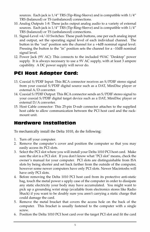
sources. Each jack is 1/4” TRS (Tip-Ring-Sleeve) and is compatible with 1/4”TRS (balanced) or TS (unbalanced) connections.
10. Analog Outputs 1-8: These jacks output analog audio to a variety of externalsources. Each jack is 1/4” TRS (Tip-Ring-Sleeve) and is compatible with 1/4”TRS (balanced) or TS (unbalanced) connections.
11. Signal-Level +4/-10 Switches: These push buttons, one per each analog inputand output, set the operating signal level of each individual channel. Thebutton in the "out" position sets the channel for a +4dB nominal signal level.Pressing the button to the "in" position sets the channel for a –10dB nominalsignal level.
12. Power Jack (9V AC): This connects to the included 9VAC "Desktop" powersupply. It is always necessary to use a 9V AC supply, with at least 3 amperecapability. A DC power supply will never do.
PCI Host Adapter Card:
13. Coaxial S/PDIF Input: This RCA connector receives an S/PDIF stereo signalfrom your coaxial S/PDIF digital source such as a DAT, MiniDisc player orexternal A/D converter.
14. Coaxial S/PDIF Output: This RCA connector sends an S/PDIF stereo signal toyour coaxial S/PDIF digital target device such as a DAT, MiniDisc player orexternal D/A converter.
15. Host Cable connector: This 25-pin D-sub connector attaches to the suppliedhost cable to allow communication between the PCI host card and the rack-mount unit.
Hardware Installation
To mechanically install the Delta 1010, do the following:
1. Turn off your computer.2. Remove the computer’s cover and position the computer so that you may
easily access its PCI slots.3. Select the PCI slot where you will install your Delta 1010 PCI host card. Make
sure the slot is a PCI slot. If you don't know what "PCI slot" means, check theowner’s manual for your computer. PCI slots are distinguishable from ISAslots by being shorter and set back farther from the outside of the computer,however some newer computers have only PCI slots. Newer Macintoshs willhave only PCI slots.
4. Before removing the Delta 1010 PCI host card from its protective anti-staticbag, touch the metal power s upply case of the computer in order to dissipateany static electricity your body may have accumulated. You might want topick up a grounding wrist strap (available from electronics stores like RadioShack) if you want to be doubly sure you aren't carrying a static charge thatcould damage the card.
5. Remove the metal bracket that covers the access hole on the back of thecomputer. This bracket is usually fastened to the computer with a singlescrew.
6. Position the Delta 1010 PCI host card over the target PCI slot and fit the card
5

loosely over it with the card in the upright position. Press the card gently butfirmly downward into the slot until the card is completely and squarelyseated in the slot. If the card seems difficult to seat, a slight rocking motionmay help.
7. Screw the Delta 1010 PCI host card’s metal bracket down into the screw holeon the back of your computer using the screw you removed in step 5 above.
8. Place the cover back on your computer.
IMPORTANT: Complete the attachment of your Delta 1010 rackmount unit and its 9v power supply to the PCI card before poweringup your computer. Never attach the rack unit to the PCI card whilethe computer is on. Doing so could damage the PCI card and voidthe warranty.
Now it is time to connect the Delta 1010 rack-mount unit to the PCI host cardthat you have just installed. With your computer turned off:
1. Mount the Delta 1010 rack-mount unit in your rack, or place it on a desktopin a convenient but secure place.
2. Connect one end of the supplied host cable to the 25-pin D-sub connector onthe rack mount unit.
3. Connect the other end of the host cable to the 25-pin D-sub connector on theDelta 1010 PCI Host card that now resides in your computer.
4. Connect the appropriate end of the 9V AC power supply into the wall outletto supply standard house current. Plug the other end into the Delta 1010 9VAC power jack.
Delta Driver Software Installation
The Delta 1010 system includes a driver CD for Windows 98/95/NT andMacintosh, containing all Windows drivers, Macintosh drivers (including allASIO and MIDI), and Delta Control Panel software. To install these on yoursystem, please follow these steps:
Windows 98 Installation
1. After installing the Delta 1010 hardware, boot your system and startWindows. During the Windows boot procedure, new hardware will beautomatically detected by the Add New Hardware Wizard as shown here.Click ‘Next>’.
6

2. The ‘Add New Hardware Wizard’ will now ask how you want to find thedriver. "Search for the best driver for your device" is already selected. Click‘Next>’.
3. Windows will give you a selection of locations to search. Make sure that only“Choose a Path” is checked, or click on the check box to do so. Insert theDriver CD into your CD ROM drive. Browse to your CD ROM open the DeltaSeries folder select the corresponding opperating system (win9x). Click‘Next>’.
4. The ‘Wizard’ reports that its Windows driver file search has found the MAudio Delta 1010. Click Next>.
5. Windows is now ready to install the driver files from the specified location.Click Next>. Windows will start to copy the files and show you a progressreport screen.
6. The Wizard reports that Windows has finished installing the software. Click‘Finish’. Your Delta 1010 is ready for action.
After completion of the driver installation, Windows may require you to restartWindows. If it does request a restart, remove the Drivers CD Disk from the CDdrive and respond “Yes”. The system will restart and your Delta 1010 is readyfor play.
Windows 95 Installation
1. After installation of the Delta 1010 hardware, boot your system and startWindows. During the Windows boot procedure, new hardware will beautomatically detected.
2. Choose the Install of "driver from disk provided by hardware manufacturer,"then click OK.
3. An ‘Install From Disk’ will prompt you to copy files from the A:\ drive. Insertthe Driver software CD into your CD ROM drive. Browse to your CD ROMopen the Delta Series folder select the corresponding opperating system
7

(win98) (these drivers also work in Win95). Click ‘Next>’. 4. Windows will start to copy files, with a progress indicator on the screen. Once
this process completes itself, your Delta 1010 will be ready for action.
After completion of the driver installation, Windows may require you to restartWindows. If it does request a restart, remove the Drivers CD Disk from the CDdrive and respond “Yes”. The system will restart and your Delta 1010 is readyfor play.
Windows NT Installation
1. Power up your computer after physically installing the Delta 1010 interfacecard.
2. Go to Start | Settings | Control Panel and double click on ‘Multimedia.’3. Click the ‘Devices’ tab, then click the ‘Add’ button.4. “Unlisted or Updated Driver" will be highlighted at the top of the list. Click
OK.5. The ‘Install Driver’ box will prompt you to insert the driver disk, and the A:
prompt will appear as the path. Insert the Drivers CD into your CD ROMdrive. Browse to your CD ROM open the Delta Series folder select thecorresponding opperating system (winNT). Click OK.
6. The "M Audio Delta Interface Card" driver will appear in the Add Unlisted orUpdated Driver dialog box. Click OK.
7. Windows NT will require you to restart your computer for the changes to takeeffect. Choose "Restart Now." Upon restart, your Delta 1010 will be ready foruse.
Macintosh Installation
1. Open the System folder on your Macintosh hard drive. In the System folder,locate the Extensions folder.
2. On you Drivers CD disk, open the Mac Delta Drivers folder. Place theextension file "Delta 1010 Driver" in your Extensions folder by clicking on itand dragging it to the Extensions folder.
3. If you are using a music program that uses ASIO drivers, it will also have anASIO folder within the application’s folder. In your Mac Delta Drivers folderyou will find three Delta 1010 ASIO drivers. For Cubase versions 4.x, use the"ASIO2 Delta1010" driver. For Metro, or earlier versions of Cubase, use the"ASIO Delta1010v3" driver. For any music program that is not ASIO2 capable,use the “ASIO Delta 1010” driver instead (check your program’sdocumentation). Place the file "ASIO Delta" in your program's ASIO folder byclicking on it and dragging it to the ASIO folder.
4. Drag the "DeltaPanel PPC" file onto your Macintosh hard drive. You can runthe Delta Control Panel from any place that's convenient, though musicsoftware applications that use ASIO will allow you to launch the Delta panelfrom within the program. If not, we suggest creating an alias of the controlpanel by highlighting it and pressing Command (Apple key)+M. Then, dragthe alias to the desktop.
8

5. With the Delta 1010 PCI card installed, restarting the computer will load theDelta 1010 extension. You will be able to visually see the Delta extension iconpass by as your system loads the extensions.
6. Go to the Apple menu |Control Panel | Sound. You should see the “built-in”sound icon, plus the Delta icon if your Delta 1010 is properly installed. If yourmusic program does use ASIO, leave the Sound Manager driver set to "built-in" for both Sound In and Sound Out. If your program does not use ASIO(check your software’s documentation) and you will be using the SoundManager to communicate with your Delta 1010, set Sound In and Sound Outto “Delta.” See the section “Hardware Settings Page” in the Delta 1010“Control Panel Software” section for information on selecting Sound Mangerinputs and outputs.
Your Delta 1010 is now ready for audio input and output. To configure the Deltafor MIDI, you will need to have Opcode’s OMS (Open Music System) installedfirst. OMS is provided on the CD that came with the unit. Opening the OMS2.3.7 folder and double-clicking on the “Install OMS 2.3.7” program will installOMS in your system. To install the Delta MIDI driver once OMS is properlyinstalled:
1. Open the “Delta Products”folder on the driver CD, then the Delta 1010 Macfolder. Locate the “Delta OMS Driver.”
2. On your Macintosh hard drive, in your System folder, you will find an “OMSFolder.”Drag the Delta OMS Driver into the OMS Folder.
3. Restart your computer.
To Configure your Delta 1010 MIDI in OMS, go to the Apple Talk Control Panelor Chooser under the Apple Menu, and make sure AppleTalk is turned off (thisis recommended, although OMS will sense that it is on and prompt you to turn itoff). If you are configuring OMS for the first time, follow these instructions toconfigure OMS.
1. In the Opcode folder, which you will find on your hard drive, locate the OMSApplications folder, then “OMS Setup." Double click on OMS Setup.
2. OMS will inform you that it has not yet been configured. Click OK.3. The Create A New Studio Setup dialog box now appears. Click OK.4. The "OMS Driver Search" box asks you to choose the port on which you've
attached the Deta MIDI (either Modem or Printer). DO NOT choose a port,just click "Search." OMS begins Searching.
5. "OMS Driver Setup" shows the "Delta" MIDI in a list when OMS successfullyfinds the driver. Click OK. OMS will now define (shows "Identifying") theDelta output port. The "OMS MIDI Device Setup" dialog box will appearshowing the Delta's output port with a check box to the left of the port,indicating that the port is enabled. Now click on OK.
6. Next, the "My Studio Setup" appears with a 'file save' dialog box over it. Youwill now need to save your new Studio Setup before you can assign aninstrument to the Delta's MIDI output and input. Assign your instrument andyou are done. You may now exit OMS Setup by quitting the application.
9
Verifying Windows Driver Installation
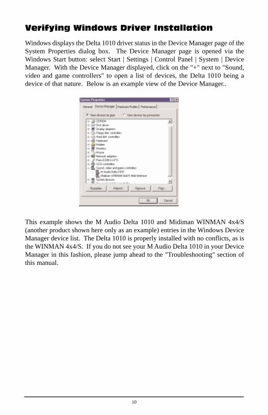
Windows displays the Delta 1010 driver status in the Device Manager page of theSystem Properties dialog box. The Device Manager page is opened via theWindows Start button: select Start | Settings | Control Panel | System | DeviceManager. With the Device Manager displayed, click on the "+" next to "Sound,video and game controllers" to open a list of devices, the Delta 1010 being adevice of that nature. Below is an example view of the Device Manager..
This example shows the M Audio Delta 1010 and Midiman WINMAN 4x4/S(another product shown here only as an example) entries in the Windows DeviceManager device list. The Delta 1010 is properly installed with no conflicts, as isthe WINMAN 4x4/S. If you do not see your M Audio Delta 1010 in your DeviceManager in this fashion, please jump ahead to the "Troubleshooting" section ofthis manual.
10

Verifying Delta Control Panel SoftwareInstallation, PC and Mac
In Windows, open the Windows Control Panel (do so via Start | Settings | ControlPanel ). If your Delta 1010 hardware and Delta Control Panel software areproperly installed, the Windows Control Panel should display an "M Audio DeltaH/W" icon. By double-clicking on that icon, you can launch the Delta ControlPanel software. For convenience, you may also create a shortcut on your desktopby dragging a copy of the "M Audio Delta H/W" icon from the Control Panel toyour Windows desktop using your mouse or trackball. After completing the dragoperation, a dialog box will ask you if you wish to create a shortcut -- click on‘Yes’. Once the shortcut is installed, all you have to do is double-click on theshortcut icon on your desktop to launch the Delta Control Panel software.
On the Macintosh, the Delta Control Panel may be placed anywhere on your harddrive, or any partition of your hard drive that you find convenient. Once thecontrol panel file has been dragged from the CD onto your hard drive, you maydouble click it to launch the Delta Control Panel software. You may create analias to the control panel by highlighting it, then holding Apple key+M. Thisalias can then be placed on your desktop.
NOTE: When using a music software program that is ASIO capable,launch the Delta Control Panel software from within that program.Some of the control panel functions will be controlled from withinthat program, such as master clock setting and sample rate, so itis desireable to launch the music program first, and then the DeltaControl Panel from the the program’s “launch” or “control panel”button. Without the music program open however, it is okay toopen the Delta panel from your desktop or other location.
Delta System Basics
Delta’s Analog Inputs/Outputs
The Delta 1010 Digital Recording System’s analog inputs and outputs arecompatible with a wide variety of audio products. On the external rack-mountunit, you will find a +4/-10 signal level pushbutton for each analog input andoutput. Pushing the button and locking it in the "out" position configures thechannel for use with +4dBu signal levels, compatible with most musicalinstruments and professional mixers. Pushing the button and locking it in the"in" position sets up the channel for -10dBV signal levels, commonly used withconsumer equipment such as CD, cassette tape and DAT players.
NOTE: In order to preserve its high dynamic range and minimizedistortion, the Delta 1010 does not have microphone pre-amplifiers
11

built into it. Therefore direct connection to a microphone is notrecommended. Instead run the microphone signal through amicrophone pre-amp (such as the Midiman "Audio Buddy™") andthen connect the pre-amp output to the input of the Delta 1010.
All analog jacks on the Delta 1010 rack-mount chassis are of the 1/4" TRS (Tip-Ring-Sleeve) variety. The TRS jacks allow connection to either balanced(typically professional) or unbalanced (typically consumer) connections. +4dBubalanced configurations provide the highest performance and should be usedwhenever possible. However, the Delta 1010’s analog connections support anycombination of balanced and unbalanced, +4dBu and –10dBV signals.
The Digital Monitor Mixer
The Delta 1010 Digital Recording System has a hardware digital audio mixerbuilt into its PCI controller chip. It accepts digital audio streams from allhardware inputs and all outgoing software audio devices, mixes them with 36-bitinternal precision and then provides the mixed output to one or more locations.For the purpose of monitoring, the output of the mixer may be routed to the firstset of Delta 1010 analog outputs (OUT1/OUT2 as a stereo pair) and/or theS/PDIF digital output. At the same time the mixer may be used for stereo mix-down, with the mixer’s output recorded into the user’s application software. Thedigital audio mixer is configured and controlled by the included Delta ControlPanel Software.
The Patchbay / Router
In addition to the built-in monitor mixer, the Delta 1010 Digital RecordingSystem includes an output patchbay/router. The patchbay/router allows eachoutput (analog or digital) to be connected to a variety of input sources. The1010’s outputs may accept audio from software sources (these output devices arevisible in your audio software applications) or from hardware sources such as theanalog and digital inputs or the monitor mixer. This capability makes the Delta1010 quite flexible for WAV output, monitoring, or directly connecting inputs tooutputs for system test purposes.
Synchronization
For proper operation, the entire Delta 1010 system is always synchronized to asingle master clock. The master clock is chosen via the Delta Control Panelsoftware and this clock may be derived from the Delta 1010’s internal crystaloscillators, S/PDIF In, or Word Clock In. Most of the time the master clock istaken from the internal crystal oscillators. However, the S/PDIF and Word Clockoptions are used in situations where the Delta 1010 must be synchronized toexternal digital audio or sample rates derived from an external device.
12

Using the initial default setting, the master clock is derived from the internalcrystal oscillators. Operation in this mode is similar to that of a generic soundcard – for instance, when a WAV file is played through the Delta drivers, thesoftware application playing the WAV file is responsible for setting the samplerate in the sound card hardware. The Delta 1010 supports these sample rates byusing either of its internal crystal oscillators and dividing the rate of thatoscillator by some value to derive the proper sample rate.
In situations where S/PDIF In is being used, the Delta 1010 should usually beconfigured to get its master clock from the S/PDIF In data stream. The reasonfor this is simple – an S/PDIF data stream coming from an external source israrely going to be in sync with the Delta 1010 (or other digital audio devices inthe system for that matter), even if the sample rates are set the same. If themaster clock were set to use the internal crystal, then the incoming S/PDIF audiowould have "pops," "crackles," and other undesirable audio artifacts present in it.Instead, setting the master clock to "S/PDIF In" will synchronize the Delta 1010to the S/PDIF input data and its digital audio will be transferred properly. Thereis one special case to consider, however. The external unit sending the S/PDIFdigital audio to the Delta 1010 may be "locked" to the word clock emitted fromthe Delta 1010, or both the external unit and the Delta 1010 are locked to thesame external word clock. In these cases, the Delta 1010 and the externalS/PDIF device are in-sync, and the S/PDIF data would therefore be in-sync withthe Delta 1010 system.
We’ve discussed internal crystals and S/PDIF In as master clock sources. Thethird option is Word Clock. Word Clock is the desirable choice when you wantto synchronize the Delta 1010 with the word clock of something else in yoursystem. That "something else" may be a another unit that has a word clockoutput, or it may be a dedicated house word clock generator.
Finally, the Word Clock and S/PDIF In options may be used to operate the Delta1010 at non-standard sample rates. When one of these two options is selected,the Delta 1010’s sample rate will automatically match that of the incoming wordclock or S/PDIF data stream.
NOTE: When either the S/PDIF In or Word Clock is selected as themaster clock source, the Delta 1010 mixer’s frequency responsewill be affected by whatever sample rates you inject at the S/PDIFIn or Word Clock In. This is because (1) the digital mixer operatesat the same sample rate as the rest of the board, and (2) samplerate and frequency response are directly correlated.
13

Using the Delta 1010 with your MusicSoftware Application
Once the Delta 1010’s hardware and driver software are properly installed, it isready for use with your music application software. Some of these applicationsmay require you to highlight or enable the Delta 1010 drivers within theprogram, and others may have a utility that analyzes or profiles the audio cardsin your system and enables the drivers. Your software should have an audiodevice driver setup page, as well as a MIDI driver setup page.
WINDOWS MME AUDIO INPUT DEVICES: All Delta 1010 analog andS/PDIF inputs may be used simultaneously for a total of 10 input channels.Within your software application(s), the names of the Delta 1010 audio inputdevices are:
PCM In 1/2 Delta-1010
PCM In 3/4 Delta-1010
PCM In 5/6 Delta-1010
PCM In 7/8 Delta-1010
S/PDIF In Delta-1010
Mon. Mixer Delta-1010
The PCM In devices allow recording a stereo stream directly from the specifiedanalog input pairs. The S/PDIF In device allows you to record a stereo streamdirectly from the S/PDIF input. The Mon. Mixer device allows stereo recordingfrom the digital "monitor" mixer built-into the Delta 1010. The audio datarecorded from this device is the mix of input and output streams that is set up inthe Delta Control Panel software (see Delta 1010 Control Panel Softwaresection).
Note that all of the input devices are stereo. Your application software may breakthese down further to "left" and "right" mono devices. Therefore you may seethem as "Left PCM In 1/2 Delta-1010, Right PCM In 1/2 Delta-1010", "LeftS/PDIF In Delta-1010, Right S/PDIF In Delta-1010", or "Left Mon. Mixer Delta-1010, Right Mon. Mixer Delta-1010," etc. from within your recording software.
WINDOWS MME AUDIO OUTPUT DEVICES: All Delta 1010 analog andS/PDIF outputs may be used simultaneously for a total of 10 output channels.Within your software application(s), the names of the Delta 1010 audio outputdevices are:
14

WavOut 1/2 Delta-1010
WavOut 3/4 Delta-1010
WavOut 5/6 Delta-1010
WavOut 7/8 Delta-1010
WavOut S/PDIF Delta-1010
All WavOut devices allow playing a stereo audio stream to the analog hardwareoutputs (for WavOut 1/2, 3/4, 5/6, 7/8), the S/PDIF hardware output (for WavOutS/PDIF), and/or into the hardware router or mixer. Your application softwaremay break each of these stereo devices down further to "left" and "right" monodevices. Therefore you may see them as "Left WavOut 1/2 Delta-1010, RightWavOut 1/2 Delta-1010", or "Left WavOut S/PDIF Delta-1010, Right WavOutS/PDIF Delta-1010", etc. from within your music software. Other software willhandle the outputs as stereo pairs, but allow you to pan audio left or right withinthe pair.
Note that each device name begins with "WavOut." This is to remind you thatthese are software devices, and not always connected directly to outputhardware. Instead they are connected to the Delta 1010’s internalpatchbay/router and may be sent to one of many destinations. For more on thepatchbay/router, see the Patchbay/Router section of the Delta Control Panelsoftware discussion.
MACINTOSH SOUND MANAGER INPUTS AND OUTPUTS: The AppleSound Manager limits the user to one stereo pair for input and one stereo pair foroutput. Within your music software, the device selection when using the SoundManager drivers for input and output will be “Sound Manager” both for inputsource and for output port.
To select the Sound Manager driver, open the Apple Menu and go to ControlPanel | Sounds. For both “Sound In”and “Sound Out,” click and highlight theDelta icon, then exit. You may select which Delta hardware stereo input pair andstereo output pair will be used for the Sound Manager’s Sound In and Sound Outin the Delta Control Panel “Hardware Settings Page” (see section, “HardwareSettings Page”under “Delta Control Panel”). Whichever stereo pair you select,the software input and output device selection within your music program willremain the same.
ASIO DRIVER INPUT DEVICES: When using the ASIO audio drivers with PCor Macintosh music programs that support ASIO-style audio, the input devicesare displayed as mono devices. Within ASIO software applications, the namesof the Delta 1010 audio input devices are:
15

Analog In1 Delta-1010
Analog In2 Delta-1010
Analog In3 Delta-1010
Analog In4 Delta-1010
Analog In5 Delta-1010
Analog In6 Delta-1010
Analog In7 Delta-1010
Analog In8 Delta-1010
S/PDIF In L Delta-1010
S/PDIF In R Delta-1010
Mon. Mixer L Delta-1010
Mon. Mixer R Delta-1010
Notice the S/PDIF In and Monitor Mixer names include "L" and "R" characters."L" indicates the left channel of the stereo stream, while "R" indicates rightchannel.
ASIO DRIVER OUTPUT DEVICES: The Delta 1010’s ASIO output devicesappear in stereo pairs. Because each device is stereo, you may see "left" and"right" references within your software application. This allows the applicationto pan audio left and right under software control. To send a signal to a DeltaASIO output 1 (for example) as a mono output send, one would choose "Analog1/2 Delta-1010" for that track’s output port, and then pan that output hard left.The ASIO outputs are named as follows:
Analog 1/2 Delta-1010
Analog 3/4 Delta-1010
Analog 5/6 Delta-1010
Analog 7/8 Delta-1010
S/PDIF L/R Delta-1010
MIDI DRIVERS: The Delta 1010 MIDI drivers, once enabled in your software’sMIDI Setup, will appear as a MIDI source and a MIDI port within that program’strack configuration windows. The MIDI input driver is named "MIDI In Delta-
16

1010", and the MIDI output driver is named "MIDI Out Delta-1010". Somesoftware applications allow you to redefine/rename these devices per supplied ormanually entered instrument definitions.
WINDOWS MULTIMEDIA SETTINGS: Windows may be set up to use theDelta 1010 as its default audio device, allowing system sounds to be sent out theDelta 1010. This also enables you to use the Delta 1010 with the sound appletsincluded with Windows. To set this up, go to Control Panel | Multimedia. In theAudio Properties page, set the Playback and Recording devices to the Delta 1010input and output devices of your choice.
Windows may also use the Delta 1010 as its default MIDI device. This allowsthe Delta 1010 to be used with the MIDI applications included with Windows.To set this up, go to Control Panel | Multimedia | MIDI. Set the Delta MIDIdriver as the default Windows MIDI driver by clicking on the "MIDI Out Delta-1010" entry in the driver list, then selecting "OK" or "Apply".
Delta 1010 Control Panel Software
ON THE PC: Once the Delta 1010 is properly installed, an "M Audio DeltaH/W" icon will be displayed in your Windows Control Panel. By double-clicking on that icon, you will launch the Delta Control Panel software. You mayalso launch the Delta Control Panel software from the desktop if you havepreviously created a shortcut there (see "Verifying Delta Control Panel SoftwareInstallation" section for instructions on how to do this). Once the Delta ControlPanel software has been opened, you will see the main panel and its several tabs.To display a desired page, click on its tab. Below are functional descriptions ofeach page.
ON THE MAC: The Delta Control Panel must be placed on the hard drive bydragging the application from the Drivers CD to any location you prefer (oneoption is to place the file in the “Apple Menu Items” folder in the system folder).Once this is done, an alias may be created by highlighting the Delta ControlPanel on the hard drive and pressing the Apple key+M. Then, this alias may bedragged to the desktop. Double clicking either will launch the control panel.Once the Delta Control Panel software has been opened, you will see the mainpanel and its several tabs. To display a desired page, click on its tab. Below arefunctional descriptions of each page. Though most of the desciptions areWindows based, the functions are identical unless otherwise indicated. Withineach section you will find the necessary name changes for using the DeltaControl Panel “ON THE MAC.”
NOTE: When using a music software program that is ASIO capable,launch the Delta Control Panel software from within that program.There will be a button in the ASIO or Audio setup page that willallow you to do so. Some of the control panel functions will be
17

controlled from within that program, such as master clock settingand sample rate, so it is desireable to launch the music programfirst, and then the Delta Control Panel from the the program’s“launch” or “control panel” button. Without the music programopen however, it is okay to open the Delta panel from your desktopor other location.
Monitor Mixer Page
The Monitor Mixer is the first page that appears when the Delta Control Panel isopened, and controls the digital mixer built into the Delta 1010’s PCI controllerchip. As described in previous sections, the output of this mixer may be assignedto the OUT1/OUT2 analog outputs and/or the S/PDIF Out digital output (thisselection is made in the Patchbay Router page). At the same time, the mixeroutputs may be recorded in stereo by software.
The Monitor Mixer Page is essentially a collection of volume level faders, audiolevel (or ‘peak’) meters, and solo/mute controls. For each mixer output and inputchannel there is one of each: a volume fader, a peak meter, a solo control, and amute control.
LEVEL FADERS: Each volume fader may be controlled by dragging the fader‘handle’ vertically with the mouse, or by clicking on the ‘handle’ to make itactive and then adjusting it with the up/down cursor keys of your computerkeyboard. Because the mixer has no gain, these faders only attenuate (reduce)the signal levels. The highest setting is 0dB, or ‘Unity Gain.’ The default fadersetting is the quietest setting, –144dB, which essentially mutes the audio. A pairof level faders may be "ganged" so that both channels may be adjusted togetheras a stereo pair.
18

Also, at the top of each fader and meter is a fader level "fine adjustment" control.Clicking on the small "up" and "down" arrows will adjust the correspondingfader setting in 0.5dB increments. Next to each fine adjustment control is anumerical fader readout that is always current and active.
PEAK METERS: Each peak meter indicates an audio signal level in "dBrelative to full-scale." This means that a full-scale signal is referred to as "0 dB"and a signal that is 12dB "quieter" than full-scale is referred to as "-12dB." Themeters are vertically color-coded into three sections: green, yellow and red. Thegreen section represents a safe zone, ranging from approximately -48dB to -12dB. Most audio signals should appropriately fill this section of the meter. Theyellow section ranges from -12dB to -3dB as the signal approaches a ‘hotter’level. For best capture resolution, recording in this area is both safe and advised.The red section of the meter ranges from -3dB to 0dB. On the input level meters,a 0dB condition indicates overload and audio clipping may occur. Therefore becareful to adjust the incoming audio levels so that they do not peak in the redsection too long (you might use the monitoring capability of the Delta 1010 to letyour ears be the judge). On all output level meters, 0dB indicates full-scaleoutput. Unlike the inputs, clipping is impossible on the outputs because of the36-bit resolution built into the mixer hardware.
MASTER VOLUME: At the left side of the Monitor Mixer page, you will seethe ‘Master Volume’ faders and peak meters. These faders have the longest‘throw’ and highest meter resolution of any level controls in the mixer page.They control the overall stereo level of the mixer output. The peak metersindicate the output signal levels with respect to full-scale and are directlyaffected by the settings of the master volume faders.
MIXER INPUTS: The ‘Mixer Inputs’ are inputs to the monitor mixer. Theseinputs accept hardware audio streams (directly from the Delta’s analog anddigital input ports) and software audio streams (digital audio generated insoftware to be output). This combination of streams makes the monitor mixerextremely flexible. Each mixer input channel has its own level fader and may bepanned anywhere in the left/right stereo field. Each input also has its own peakmeter. The peak meters indicate the incoming "pre-fader" levels of the incomingaudio and are therefore not affected by the fader settings. However, the inputfaders do affect the levels of the signals exiting the mixer and you will see theaffect of the input faders on the output "Master Volume" peak meters.
Because of the large number of mixer inputs, not all inputs are displayedsimultaneously. You may use the scroll bar at the bottom of the Delta ControlPanel to scroll the view left or right. On the PC, from far left to right the inputsare labeled "WavOut 1/2" through "WavOut 7/8," then "WavOut S/PDIF." Theseinputs accept the digital audio streams being sent from your software application(or Windows) to the driver devices with those same names. Each name beginswith "WavOut" to remind you that these are software streams and may not
19

necessarily be routed to any physical outputs (see Patchbay/Router Page). On theMac, these inputs are labeled “SM/ASIO,” as these software streams will bereceiving their digital audio either from the Sound Manager or the ASIO driver,depending on your selection.
Further to the right are more channels, labeled "H/W In S/PDIF" and "H/W In1/2" through "H/W In 7/8." These mixer inputs are audio streams from thephysical Delta 1010 hardware inputs, hence the "H/W" at the front of each label.These labels are consistent on both the Mac and PC.
PAN: Each mixer input may be individually panned anywhere in the stereooutput mix. A pan control is positioned directly under each input channel peakmeter and has the appearance of a small vertical pointer. To make a coarseadjustment, click on the pan control with your mouse and drag it to the desiredposition. For finer adjustment (in 1% increments), you may click on the pancontrol to make it active, and then use the left/right or up/down cursor keys onyour computer keyboard. Either way, while the pan setting is being adjusted, itsvalue will appear numerically in the Master Volume’s status box (below theMaster Volume Stereo Gang control) as a percentage from left pan to right pan:-100% represents far left, +100% represents far right, and 0% represents thecenter.
SOLO: Each mixer input channel has a "Solo" checkbox associated with it.Clicking on and activating a Solo box will solo the selected channel byessentially muting all other signals. When more than one channel has Soloselected, all solo channels will be summed to the solo ‘buss’ (path), which iswhat one might consider an ‘in place’ solo as opposed to a PFL, or pre-faderlisten (levels and pans still apply). Deactivating all solo boxes will return allinput channels to their previous mute/unmute states.
MUTE: Every mixer input channel has a "Mute" checkbox associated with it.Clicking on and activating the Mute box will remove that signal from the stereobuss. Deactivating the Mute box will add the signal back into the stereo buss.
STEREO GANG: All input channel pairs have a "Stereo Gang" capability.Clicking on and activating the Stereo Gang checkbox will link (or "gang") theleft/right faders so that both channels may be adjusted together as a stereo pair.
Patchbay/Router Page
The Patchbay/Router page allows you to connect each of the Delta 1010’shardware outputs (4 pairs of analog outputs and 1 pair of digital output channels)to specific audio sources within the Delta 1010 board. To display this page, clickthe "Patchbay/Router" tab of the Delta Control Panel.
ON THE MAC: Please substitute the name “SM/ASIO” where referrences are
20

made to “WavOut.” SM/ASIO are the software outputs on the Mac, whileWavOut are the software outputs on the PC.
The leftmost vertical column of Patchbay/Router page, "H/W Out 1/2," connectsthis analog stereo pair to one of eight stereo sources:
1. The default setting, "WavOut 1/2", connects ports OUT1 and OUT2 to yourmusic software or Windows multimedia applet. In other words, when musicsoftware plays audio to the device named "WavOut 1/2 Delta-1010" it will berouted directly to the "hardware" analog outputs 1 & 2 of your 1010 rack-mount chassis.
2. The second option, "Monitor Mixer", connects ports OUT1 and OUT2 to theoutputs of the Delta 1010 monitor mixer. For more information of thecapabilities of the monitor mixer, please see the section "Monitor Mixer Page".
3. The third option, "S/PDIF In", connects ports OUT1 and OUT2 directly to thehardware S/PDIF input on the Delta 1010 PCI host card. The left channel ofthe S/PDIF In is routed to OUT1 and the right channel of the S/PDIF In isrouted to OUT2.
4. The fourth option, "S/PDIF In (L/R Rev.)", functions identically to the thirdoption, except that the left and right channels are swapped. Therefore in thismode, the left channel of the S/PDIF In is routed to OUT2 and the rightchannel of the S/PDIF In is routed to OUT1.
5. Selections five through eight connect the hardware analog inputs 1 & 2, 3 & 4,5 & 6, or 7 & 8 (respectively) directly to the 1010’s hardware analog outputs 1& 2. For example, if "H/W In 1/2" were selected, any signal present at the IN1port will be copied to OUT1, and any signal present at the IN2 port will becopied to OUT2. This same behavior applies to "H/W In 3/4", "H/W In 5/6",and "H/W In 7/8" when selected.
The next three vertical columns of the Patchbay/Router page (from left to right),"H/W Out 3/4," "H/W Out 5/6," and "H/W Out 7/8," connect these hardwareanalog outputs to one of seven sources. Since the three columns functionidentically, we’ll use "H/W Out 3/4" as the example:
1. The default setting, "WavOut 3/4", connects ports OUT3 and OUT4 to yourmusic software or Windows multimedia applet. In other words, when musicsoftware plays audio to the device named "WavOut 3/4 Delta-1010" it will berouted directly to the "hardware" analog outputs 3 & 4 of your 1010 rack-mount chassis.
2. The second option, "S/PDIF In", connects ports OUT3 and OUT4 directly tothe hardware S/PDIF input on the Delta 1010 PCI host card. The left channelof the S/PDIF In is routed to OUT3 and the right channel of the S/PDIF In isrouted to OUT4.
3. The third option, "S/PDIF In (L/R Rev.)", functions identically to the secondoption, except that the left and right channels are swapped. Therefore in thismode, the left channel of the S/PDIF In is routed to OUT4 and the rightchannel of the S/PDIF In is routed to OUT3.
4. Options four through seven connect the hardware analog inputs 1 & 2, 3 & 4,
21

5 & 6, or 7 & 8 (respectively) directly to the 1010’s hardware analog outputs 3& 4. For example, if "H/W In 1/2" were selected, any signal present at the IN1port will be copied to OUT3, and any signal present at the IN2 port will becopied to OUT4. This same behavior applies to "H/W In 3/4", "H/W In 5/6",and "H/W In 7/8" when selected.
The rightmost vertical column of Patchbay/Router page, "H/W Out S/PDIF,"connects the Delta 1010’s hardware S/PDIF outputs to one of eight sources:
1. The default setting, "WavOut S/PDIF", connects the S/PDIF Out port to yourmusic software or Windows multimedia applet. In other words, when musicsoftware plays audio to the device named "WavOut S/PDIF Delta-1010" it willbe routed directly to the hardware S/PDIF output on your Delta 1010 PCI hostcard.
2. The second option, "Monitor Mixer", connects the S/PDIF Out port to theoutputs of the Delta 1010 monitor mixer. For more information on thecapabilities of the monitor mixer, please see the section "Monitor Mixer Page".
3. The third option, "S/PDIF In", connects the S/PDIF Out port directly to thehardware S/PDIF input on the Delta 1010 PCI host card. The left channel ofthe S/PDIF In is routed to the left channel of S/PDIF Out and the rightchannel of the S/PDIF In is routed to the right channel of S/PDIF Out.
4. The fourth option, "S/PDIF In (L/R Rev.)", functions identically to the thirdoption, except that the left and right channels are swapped. Therefore in thismode, the left channel of the S/PDIF In is routed to the right channel ofS/PDIF Out and the right channel of the S/PDIF In is routed to the leftchannel of S/PDIF Out.
5. Selections five through eight connect the hardware analog inputs 1 & 2, 3 & 4,5 & 6, or 7 & 8 (respectively) directly to the 1010’s S/PDIF Out port. Forexample, if "H/W In 1/2" were selected, any signal present at the IN1 portwill be sent to the left channel of the S/PDIF Out, and any signal present atthe IN2 port will be sent to the right channel of the S/PDIF Out. This samebehavior applies to "H/W In 3/4", "H/W In 5/6", and "H/W In 7/8" whenselected.
At this point, you may begin to realize the versatility of the Monitor Mixer andthe Patchbay/Router, and the relationship between the two. You may want to re-read this section and make some practice adjustments within the Delta ControlPanel software to become proficient in routing and mixing. If somewhere in theprocess you become confused, you may always restore the default settings to usethe card as a straight 10-in 10-out device -- just choose the topmost option ineach of the Patchbay/Router columns.
Hardware Settings Page
The Hardware Settings page of the Delta Control Panel gives you control overmiscellaneous features of the Delta 1010. To display this page, click the"Hardware Settings" tab of the Delta Control Panel.
22

MASTER CLOCK: This section allows you to select the source of the board’smaster clock: Internal Xtal (crystal), S/PDIF In, or Word Clock. Master clockoperation is outlined in the Synchronization section of this manual. Internal Xtalis the default setting. Be sure to select "S/PDIF In" if you will be recording ormonitoring an S/PDIF stream, or "Word Clock" if you wish to synchronize yourdigital audio with a source device that is Word Clock capable.
NOTE: If "S/PDIF In" is selected as the master clock source, besure to supply a valid S/PDIF signal to the board’s active S/PDIFinput. Otherwise, erratic timing and/or improper sample rates willbe experienced. The same is true for selecting "Word Clock" as themaster clock setting – make sure there is a valid word clock signalpresent at the Delta 1010’s Word Clock In.
Once a master clock source has been selected, its synchronization status iscontinually monitored and displayed below the master clock radio buttons. Ifinternal crystal is selected, the status display will always say "Locked." On theother hand, if S/PDIF In or Word Clock is selected as the master clock source,the control panel will display "Locked" only when a valid S/PDIF or Word Clocksignal is detected. It will display "Unlocked" when there is no signal at theselected input, or when the signal is corrupt or invalid for any reason.
CODEC SAMPLE RATE: This section indicates the present board sample rate,as set by application software. The sample rate selected here will be used todrive the digital mixer and all outputs. The "Rate Locked" checkbox is used toforce a sample rate upon the system. It is disabled by default to allow softwareaccess to all supported sample rates. When checked, it causes the driver to onlyoperate at the selected sample rate. This means that any application that attemptsto open the Delta 1010 driver at a sample rate other than the one selected herewill fail to do so and will post an error message. "Reset Rate When Idle" isselected when you want the sample rate to return to a particular setting when asoftware application is not actively using the board. This is particularly handyfor keeping the digital mixer running at a specific sample rate.
NOTE: Because the digital monitor mixer runs at the sample rateof the rest of the board, and because sample rate directly affectsfrequency response, it may be desirable to keep the sample rate ator above 44.1 kHz while using the monitor mixer. This isaccomplished by enabling "Reset Rate When Idle" and selecting asample rate of 44.1 kHz or greater.
S/PDIF SAMPLE RATE: When using S/PDIF In as your master clock, thissection tells the driver what the expected S/PDIF input sample rate is. Thesection is only displayed when the board is set to use S/PDIF In as the masterclock source. From the list, select the sample rate closest to that of the S/PDIFinput data. The sample rate selected here will be the only sample rate availableto the software applications. Therefore, you must set your audio software
23

application to this same sample rate or else the application will display an errormessage.
NOTE: When S/PDIF In is the master clock source, the digitalmonitor mixer will run at the sample rate received at the S/PDIF In.Since frequency response and sample rate are directly related, themixer frequency response will be directly related to the sample rateof the S/PDIF input data.
WORD CLOCK SAMPLE RATE: When using Word Clock In as your masterclock, this section tells the driver what the expected word clock input sample rateis. The section is only displayed when the board is set to use Word Clock In asthe master clock source. From the list, select the sample rate closest to that ofthe incoming word clock. The sample rate selected here will be the only samplerate available to the software applications. Therefore, you must set your audiosoftware application to this same sample rate or else the application will displayan error message.
NOTE: When Word Clock is the master clock source, the digitalmonitor mixer will run at the sample rate received at the WordClock in. Since frequency response and sample rate are directlyrelated, the mixer frequency response will be directly related to thesample rate of the S/PDIF input data.
MULTITRACK DRIVER DEVICES: The Delta 1010 drivers intelligentlysynchronize the beginning of recording and playback across all audio devices onthe board. When using application software that is capable of using multiplechannels simultaneously, select "Single and In-Sync" to ensure that all audiochannels will begin playback and/or recording at the same time. Otherwiseselect "Independent" to allow the audio channels to play independently – thissetting may be desirable if more than one application needs to access the Delta1010 simultaneously.
DMA BUFFER SIZES: This section specifies the amount of system memorydedicated to digital audio buffering. Setting a buffer size that is too small mayresult in clicks or pops in the audio stream as some data may be lost. Largerbuffers cause slightly more latency but prevent the pops and clicks that mightoccur with smaller buffer sizes – the default settings are recommended but youmay desire to tweak these default settings to suit your tastes. This buffer sizemust be set in the Delta Control Panel before you launch your music software.When using ASIO with the Delta 1010, set the buffer size in the control panel,then exit the control panel. After doing so, launch your music software.
ON THE MAC: The Hardware Settings Page in the Macintosh version of theDelta Control Panel also contains software switches that allow you to selectwhich Delta input and output stereo pair will be used by the Sound Manager, ifand when you choose the Delta as the Sound Manager input and output device.
24
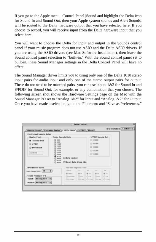
If you go to the Apple menu | Control Panel |Sound and highlight the Delta iconfor Sound In and Sound Out, then your Apple system sounds and Alert Sounds,will be routed to the Delta hardware output that you have selected here. If youchoose to record, you will receive input from the Delta hardware input that youselect here.
You will want to choose the Delta for input and output in the Sounds controlpanel if your music program does not use ASIO and the Delta ASIO drivers. Ifyou are using the ASIO drivers (see Mac Software Installation), then leave theSound control panel selection to “built-in.” With the Sound control panel set tobuilt-in, these Sound Manager settings in the Delta Control Panel will have noeffect.
The Sound Manager driver limits you to using only one of the Delta 1010 stereoinput pairs for audio input and only one of the stereo output pairs for output.These do not need to be matched pairs- you can use inputs 1&2 for Sound In andS/PDIF for Sound Out, for example, or any combination that you choose. Thefollowing screen shot shows the Hardware Settings page on the Mac with theSound Manager I/O set to “Analog 1&2” for Input and “Analog !&2” for Output.Once you have made a selection, go to the File menu and “Save as Preferences.”
25

S/PDIF Page
The S/PDIF page of the Delta Control Panel configures the S/PDIF output formatand displays the status of the S/PDIF input. To display this page, click the"S/PDIF" tab of the Delta Control Panel software.
DIGITAL INPUT: This group box displays the current S/PDIF input status.The Delta 1010’s S/PDIF receiver is capable of recognizing a valid input signalversus an invalid, corrupt or non-present one. When a valid signal is detected atS/PDIF In, this group box displays "Valid Input Detected." When an invalidsignal is detected or no signal is present, the group box displays "Invalid or NotPresent." Below this message are two ‘grayed-out’ buttons: "Coax(RCA)" and"Optical." These are functions of the Delta DiO 2496, another product in the MAudio Delta line, one with both optical and coaxial S/PDIF inputs. Thesecontrols do not apply to the Delta 1010.
DIGITAL OUTPUT FORMAT: Within the "Digital Output Format" group,you choose the digital audio format of the S/PDIF output. The default setting,"Consumer," is a true S/PDIF format and is recognized by all consumer devices.The alternate "Professional" setting is an AES/EBU type data stream, butelectrically S/PDIF. This is a work-around that is recognized by some but not allAES/EBU devices.
For both consumer and professional output formats, the "Advanced" checkboxwill allow you to force a few particular status bits in the outgoing S/PDIF signal.The advanced option is for expert users only; however, if you decide to goexploring, change a few bit settings and get lost, you can always select the"Restore Defaults" button to restore the outgoing status bits to their factorysettings. When "Consumer" and "Advanced" are both selected, the group"Consumer Format Advanced Settings" will appear. When "Professional" and"Advanced" are both selected, the group "Professional Format AdvancedSettings" will appear. These groups are described below:
CONSUMER FORMAT ADVANCED SETTINGS (Copy Mode): Copyprotection, also known as Serial Copy Management System (SCMS), is writteninto the S/PDIF subcode, a reserved part of the S/PDIF digital stream that isindependent of the actual audio data being transmitted. It can be used to inhibitthe amount of copies that can be made, or allow for unlimited copying. ThreeSCMS modes are available. "Original (Copy Permitted)" indicates that thesource material may be copied by a receiving device. "1st Generation" indicatesthat the source material is a first generation copy. Most devices that are capableof recording will reject material with this SCMS mode set. The final option is"No SCMS" which may be used to override the other two modes and allow arecording device to successfully record the audio data. Different manufacturers’products may interpret these codes differently and require you to set these bits by"trial-and-error" until proper operation is achieved.
26

CONSUMER FORMAT ADVANCED SETTINGS (Emphasis): This statusbit is used to indicate if pre-emphasis has been applied to the outgoing digitalaudio signal. The default is "None" and rarely will any user want to set the valueto "50/15uSec" unless the transmitted audio has been encoded with 50/15uSecpre-emphasis.
PROFESSIONAL FORMAT ADVANCED SETTINGS (Data Type): Theuser may assign the outgoing data as audio or non-audio data. Many devicesignore this setting. The obvious default is "audio."
PROFESSIONAL FORMAT ADVANCED SETTINGS (Emphasis): Theuser may choose to indicate or not indicate if pre-emphasis has been applied tothe outgoing digital audio signal. The default is "None" and rarely will any userwant to set the value to "CCITT" or "50/15uSec" unless the transmitted audio hasbeen encoded with one of those types of pre-emphasis.
About Page
The "About" page, while displaying the handsome M Audio logo and applicablecopyright information, also reports the driver version and control panel softwareversion. If you have Internet browsing capabilities and are currently connectedto the Internet, clicking on the Midiman copyright will link you to the M Audio/ Midiman web site (PC only).
Save, Delete, Load Buttons; H/W Installed
On the PC, at the rightmost side of the Delta Control Panel are the Save, Loadand Delete buttons as well as an "installed hardware" set of radio buttons. Thesecontrols appear regardless of what Delta Control Panel page is being displayed.To save your settin
SAVE, DELETE, LOAD: The Delta Control Panel always retains the lastsettings entered. However the Save, Delete, and Load functions expand thiscapability to store different sets of control panel settings using differentconfiguration file names. These configurations are then available for recall at alater date and time.
Clicking the ‘Save’ button brings up a dialog box prompting you to name the currentconfiguration. Once you have done this, click ‘OK’, and your current configurationhas been saved to disk. If you decide that you no longer need a particularconfiguration, click the ‘Delete’ button. Highlight the name of the configuration filethat you wish to delete, and click the ‘OK’ button. To recall or reload a savedconfiguration, click the ‘Load’ button. Highlight the name of the configuration filethat you wish to recall, and click ‘OK’. Those settings will now appear in the DeltaControl Panel and the driver will automatically update the hardware.
27

H/W INSTALLED: Up to four Delta cards may be installed in a system at onetime. (Note: this option may not exist in the Delta software drivers at the timeof the first release.) This section displays all installed Delta cards, and allowsyou to select which particular card is under the control of the control panelsoftware. To select a card for configuration, click the radio button to the left ofthat particular card in the “H/W Installed” list.
ON THE MAC: To save your Delta control Panel settings, go to the File menuand select “Save,”or “Save as.” A dialog box will appear, promting you to namethe current configuration. Once you have done so, click the Save button. To savethe current settings as your default, go to the File menu and choose “Save asPreferences.”
In the upper righthand corner of the control panel is a “H/W Installed” drop-down list. At the time of this writing, the Delta Mac ASIO drivers will supportonly a single Delta device, and of course the sound Manager will support onlyone stereo pair regardless of how many audio cards are installed in your system.The H/W Installed list will display “Delta 1010 as the active device in the controlpanel”.
Delta 1010 Recording Tutorials
In this section we will explore a few sample setups for recording and playbackusing the Delta 1010 Digital Recording System. This is by no means anexhaustive tutorial but its intent is to help you understand most of the Delta1010’s feature set. Before beginning, you should open your music software andprofile the Delta 1010, enable its drivers, or otherwise setup the software foroperation with the Delta 1010.
NOTE: All of these examples refer to the Windows MME drivernames. If you’re using ASIO drivers, you’ll need to substitute theappropriate driver names when referring to software inputs oroutputs.
Typical Setup #1
Let’s assume for this setup that we’re recording a guitar and vocal, thenoverdubbing another guitar and vocal track while listening to the first tracks.The following diagram shows a microphone pre-amp and direct box being used(in this case, the Audio Buddy™ by Midiman), and a stereo sound system. Thepre-amp and direct box are required for the mic and guitar. Many instruments,such as MIDI modules or keyboards, may be connected directly to the Delta1010’s inputs.
28
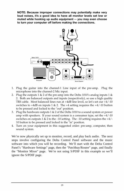
NOTE: Because improper connections may potentially make veryloud noises, it’s a good idea to have all monitor levels set low ormuted while hooking up audio equipment -- you may even chooseto turn your computer off before making the connections.
1. Plug the guitar into the channel-1 Line input of the pre-amp. Plug themicrophone into the channel-2 Mic input.
2. Plug the outputs 1 & 2 of the pre-amp into the Delta 1010’s analog inputs 1 &2. Both are balanced outputs and inputs (respectively), so use a high qualityTRS cable. Most balanced lines run at +4dB line level, so let’s set our +4/-10switches to +4dB on inputs 1 & 2. The +4 setting requires the +4/-10 buttonto be pressed and locked to the "out" position.
3. Plug the hardware outputs 1 & 2 of the Delta 1010 to a sound system or poweramp with speakers. If your sound system is a consumer type, set the +4/-10switches on outputs 1 & 2 to the –10 setting. The –10 setting requires the +4/-10 button to be pressed and locked to the "in" position.
4. Turn on your equipment in this suggested order: pre-amp, computer, thensound system.
We’re now physically set up to monitor, record, and play back audio. The nextsteps involve configuring the Delta Control Panel software and the musicsoftware into which you will be recording. We’ll start with the Delta ControlPanel’s "Hardware Settings" page, then the "Patchbay/Router" page, and finallythe "Monitor Mixer" page. We’re not using S/PDIF in this example so we’llignore the S/PDIF page.
WordclockIn Out
Host Cable
WordclockIn Out
Host Cable 9 VAC
Ins
Outs
8 78 7 66 55 44 33 22 11Delta 1010 and the M Audio product line isproduced by MIDIMAN.
Delta 1010 and the M Audio product line areproduced by MIDIMAN.
+4 -10
Mic
Guitar
MIDIMANAudio Buddy
Ch. 1
Ch.2
Delta 1010
Sound SystemComputer
29

5. Open the Delta Control Panel by double clicking the icon in your WindowsControl Panel, and then click on the ‘Hardware Settings’ tab.
6. Select ‘Internal Xtal’ as the master clock source. This allows the Delta 1010 toderive its sample rates from its internal clock oscillator. ‘Internal Xtal’ is thedefault setting for the Delta Control Panel, so selecting it may not be necessary(it may already be selected).
7. Under "CODEC Sample Rate," verify that the "Rate Locked" checkbox is notactivated. This will allow your application software to set the Delta 1010sample rate as it pleases.
8. Since this example will include the use of the monitor mixer, we will activatethe "Reset Rate When Idle" feature. This will make sure the monitor mixer isrunning at a decent sample rate while the system is idle – this prevents themixer sample rate from being set too low and therefore lowering its frequencyresponse. Select a sample rate in the "CODEC Sample Rate" group to use asthis idle sample rate. Choose a 44.1kHz or higher setting for best results, andselect the same sample rate you will be using in your application if possible.We’ve chosen 48,000kHz for this example.
Now click on the Delta Control Panel’s "Patchbay/Router" tab. In the firstcolumn of the Patchbay/Router page, click the radio button "Monitor Mixer" toconnect the monitor mixer’s stereo output directly to Delta analog outputs OUT1and OUT2. Now, everything that we hear at outputs 1 & 2 will reflect oursettings in the Monitor Mixer page.
30

Select the "Monitor Mixer" tab of the Delta Control Panel. The default MasterVolume fader settings are 0dB and unmuted, and all other faders are set to fullattenuation (-144dB) and muted. We will need to adjust these to our preference.The screen capture on the next page shows the settings that we wish to achieve.
31

9. In the Mixer Input column labeled "WavOut 1/2," click on each fader handleand drag it up to the 0dB setting. Also, deactivate (uncheck) each WavOut1/2 mute box to unmute the channels. This will allow us, once we’verecorded into a music software program, to hear those software outputs uponplayback.
10. Using the scroll bar at the bottom of the control panel, scroll to the right untilyou see the column labeled "H/W In 1/2." Strum the guitar, and you shouldsee an indication in the left meter, which represents signal levels from theDelta analog input 1. Test the mic, and you should see an indication in theright meter, which represents signal levels from Delta hardware input 2.
11. Adjust the gain on the pre-amp so that you’re seeing a good level on the inputmeters, about –6dB to –3dB in the loudest parts (this is playing it a safebecause you don’t want to hit 0dB and clip). Make similar adjustments for themicrophone, using the right fader. These are the levels at which the signalswill be recorded.
12. Now let’s set the levels at which you will monitor the mic and guitar whilerecording. These are not to be confused with the levels that are recorded bythe software – these levels are merely monitor levels that appear in the mixeroutputs (in this case at Delta 1010 analog outs 1 & 2). Click on the left faderhandle of H/W In 1/2, and drag it about halfway up. Strum the guitar. If it’snot loud enough, bring it up all of the way. If it is still not loud enough, youwill have to raise the listening level of your sound system. Make similaradjustments for the microphone, using the right fader.
13. Now fine-tune your monitor levels. Sing and play guitar, adjusting yourlistening levels using the H/W In 1/2 faders so that you have a comfortableblend of guitar and mic levels.
32

Now is the time to launch your music software and set it up to record andplayback audio tracks. We’re going to speak in general terms here, since setupwithin software programs will vary somewhat. Minimize your Delta ControlPanel so that you can easily access it from your Windows taskbar. Then openyour music software program.
14. First set up the sample rate in the software application. This operation willdepend on the software. Choose a sample rate that is high enough to capturethe frequency response of the guitar and vocals. A general rule of thumb is tomultiply the highest frequency you would like to capture by two and addmaybe a little on top of that – that gives you a suitable sample rate. Also keepin mind that if the final results of your work will end up on a CD-ROMburned from your WAV file, you probably want to use 44.1kHz, the nativesample rate of "redbook" CD audio.
15. In your software application, set the ‘source’ or ‘input port’ to "Left PCM In1/2 Delta-1010" on track one, and "Right PCM In 1/2 Delta-1010" on tracktwo. Arm the tracks for recording. Track one is now set up to record theguitar, and track two the microphone. If your software requires this, set thesoftware’s clock source to ‘Audio.’
16. Press record on your software’s transport bar. Record a take of your guitarand vocals. Understand that while recording, you are monitoring the Deltainputs by way of the Monitor Mixer settings for H/W In 1/2, and accordingto the selection of ‘Monitor Mixer’ within the Patchbay/Router page. At thesame time, your software is recording from H/W In 1/2 but at the levels thatwere set up with the pre-amp.
17. When you are done playing, stop the recording software and rewind the take.Before playing back what you’ve recorded, you will need to assign therecorded tracks to output devices on the Delta 1010.
Note: For efficiency’s sake, this step could have taken place whileyou were setting up the recording track assignments. However,since this step only affects playback and does not affect therecording setup in any way, we’ve placed it here to lessenconfusion.
Assign software track 1 to output device "WavOut 1/2 Delta-1010" and pan thetrack (within your software) all the way to the left (hard left). Then assign track2 to output device "WavOut 1/2 Delta-1010" and pan the track all the way to thehard right. Now, when you start playback, track one (guitar) will be sent to theDelta software (WavOut) output 1, and track two (mic) to Delta software output 2. These two software outputs are inputs to the monitor mixer, thereforethe recorded guitar and mic channels will be sent to the monitor mixer, levels willbe modified by the mixer and the output of the mixer will be heard at analogoutputs 1 & 2.
18. Start playback from your software’s transport bar. Open the Delta ControlPanel and go to the Monitor Mixer page. Observe the meters at "WavOut 1/2"– these are the playback levels of your guitar and mic. Adjust the faders and
33

34
mute controls so that you may hear the guitar and mic at the appropriatelevels and mix. These are the levels at which you may monitor the pre-recorded tracks while you overdub (record other tracks while listening to thefirst) additional parts.
Let’s assume that you like this take, and wish to overdub an additional guitar anda harmony vocal. We can still use hardware inputs 1 & 2 of the Delta. We’re setup to do so and there’s no reason to change these inputs. Let’s set ourselves upto overdub these next two tracks. We will record the next two tracks of materialto tracks 3 & 4 of the software:
19. Back in your music program, set the ‘source’ or ‘input port’ to "Left PCM In1/2 Delta-1010" on track three, and "Right PCM In 1/2 Delta-1010" on trackfour. Arm the tracks for recording. Track three is now set up to record theguitar, and track four the microphone. Usually at this point you would wantto return to the Delta Control Panel monitor mixer to set up levels. However,because you will be recording the same instruments that you did on the firsttwo tracks, you probably won’t need to adjust input or monitoring levels.
20. Press record on your software’s transport bar. Record a take of your newguitar and vocal tracks. Because you have set up the first two tracks to playback through the monitor mixer, you should hear those original tracks alongwith the ones that you are now recording.
21. When you are done playing, stop the recording software and rewind the take.Before playing back what you’ve recorded, you will need to assign the newlyrecorded tracks to output devices on the Delta 1010. In your software, set theoutput ports of tracks three and four to "WavOut 3/4 Delta-1010." Pan trackthree all of the way to the left (hard left), and pan track four hard right. Nowtrack three (guitar) will be sent to the Delta software output 3, and track four(mic) to Delta software output 4.
22. Press play on your software’s transport bar. Understand now that the fourrecorded tracks from the software are being sent to WavOut 1, WavOut 2,WavOut 3, and WavOut 4 simultaneously. Therefore they are all being inputto the monitor mixer and their playback levels can be controlled at thecorresponding channels of the monitor mixer. Open the Monitor Mixer pageof the Delta Control Panel and adjust the levels of the four channels accordingto your taste. You may also experiment with the Mute and Solo controls whilelistening to the playback. Note also that the mixer continues to monitor theguitar and mic at analog inputs 1 & 2!
At this point, you should be able to see how this multi-tracking session isdeveloping. As we add more tracks within our music software, we set them tothe next pair of Delta software outputs (3/4, then 5/6…), and bring up the fadersof those software inputs in the monitor mixer (WavOut 3/4, WavOut 5/6…). Wecontinually monitor from the Delta hardware outs 1 & 2, via the ‘Mon. Mixer’setting as the monitor ‘source’ in the Patchbay/Router page, and adjusting ourmix of the software outputs (and the way we monitor our guitar and vocal at theinputs) via the Monitor Mixer settings.

35
Notice that if we continue to overdub past track 8, we run out of WavOut devicesto assign to. In this case, you may want to do some of your level mixing withinthe software application if it supports it. Most applications will allow you toassign more than one track to an output device and then set the relative levels ofthe tracks within the software, letting the software do the mixing. In thisexample you could have assigned all of the playback tracks to "WavOut 1/2" andlet the software handle the mix.
Typical Setup #2
This section contains a multi-tracking example illustrating another way to use theDelta 1010 and its control panel software. We’re going to use multiple inputsand multiple outputs, so a mixing console that will handle multiple inputs mustbe used on the output side of the Delta 1010. A discussion of mixing consolesand their use will follow in Appendix B. For simplicity in this example we’ll usepre-amps to get the signal to the Delta 1010, and a mixer connected to a soundsystem to handle the multiple outputs.
Let’s say that we’re recording a band. We’ve got 6 mics on the drum set, with theguitar and bass going ‘direct’ into the pre-amps.
NOTE: Because improper connections can potentially make veryloud noises, it’s a good idea to have monitor levels down whilehooking up audio equipment – you may choose to turn yourcomputer off before making the connections.
1. Plug the microphones into the mic inputs 1-6 of the pre-amps, and placearound the drums in some strategic fashion (you may want to consult a book
WordclockIn Out
Host Cable
WordclockIn Out
Host Cable 9 VAC
Ins
Outs
8 78 7 66 55 44 33 22 11Delta 1010 and the M Audio product line isproduced by MIDIMAN.
Delta 1010 and the M Audio product line areproduced by MIDIMAN.
+4 -10
MIDIMANAudio Buddy
Delta 1010
MIDIMANAudio Buddy
MIDIMANAudio Buddy
MIDIMANAudio Buddy
Mixer
Computer

36
on recording techniques). Plug the guitar and bass into the high impedanceinputs 7 & 8 of the pre-amps.
2. Plug the outputs of the pre-amps 1-8 into the hardware inputs 1-8 of the Delta1010. Usually pre-amp outputs are balanced, so if they are, use TRS cablesand set the Delta +4/-10 input switches to the +4dB setting.
3. Plug the hardware outputs 1-8 of the Delta 1010 into your mixer’s inputs 1-8(using 1-8 is recommended for convenience, but not necessary). Some mixersrun at –10 line level, and some at +4. Many mixers may be set either way andactually have their own +4/-10 switch(es). Let’s assume that our mixer runsat +4, so set the Delta +4/-10 output switches to +4. At this point we’ll assumethat all mixer faders are down, and that the mixer is plugged into a soundsystem for monitoring.
We’re now physically set up to monitor, record, and playback audio with theDelta 1010 and related components. The next steps involve the settings in theDelta Control Panel. We’ll use the same settings as Typical Setup #1 for theDelta Control Panel’s ‘Hardware Settings’ page, i.e. "Internal Xtal", "Reset RateWhen Idle" and 48kHz idle sampling rate. The settings that we’ll focus on willinvolve the ‘Patchbay/Router’ page. We won’t be using the Delta 1010’sMonitor Mixer, so we’ll ignore the ‘Monitor Mixer’ page.
4. Open the Delta Control Panel software and click on the Patchbay/Router tab.5. For the first stereo pair, H/W Out 1/2, click the radio button in that column
for "H/W In 1/2." For the second stereo pair, H/W Out 3/4, click the radiobutton in that column to "H/W In 3/4." Continuing with this pattern, set theH/W Out 5/6 column to "H/W In 5/6," and the H/W Out 7/8 column to"H/W In 7/8." Using these settings for the Patchbay/Router page connectseach hardware input directly to a hardware outputs. These settings will allowus to monitor the inputs to the Delta 1010 (drums, guitar, and bass) while weare recording.
6. Minimize the Delta Control Panel to the Windows taskbar.7. Open your music software program. Set up eight tracks for recording:

Track one -- Left PCM In 1/2 Delta-1010
Track two -- Right PCM In 1/2 Delta-1010
Track three -- Left PCM In 3/4 Delta-1010
Track four -- Right PCM In 3/4 Delta-1010
Track five -- Left PCM In 5/6 Delta-1010
Track six -- Right PCM In 5/6 Delta-1010
Track seven -- Left PCM In 7/8 Delta-1010
Track eight -- Right PCM In 7/8 Delta-1010
8. Now we want to set up the output ports for the eight tracks.
Track one -- WavOut 1/2 Delta-1010, panned hard left.
Track two -- WavOut 1/2 Delta-1010, panned hard right.
Track three -- WavOut 3/4 Delta-1010, panned hard left.
Track four -- WavOut 3/4 Delta-1010, panned hard right.
Track five -- WavOut 5/6 Delta-1010, panned hard left.
Track six -- WavOut 5/6 Delta-1010, panned hard right.
Track seven -- WavOut 7/8 Delta-1010, panned hard left.
Track eight -- WavOut 7/8 Delta-1010, panned hard right.
9. Bring up the meter view in your music software, and let’s start to get somelevels here. Let’s say that your hardware input 1 is the kick drum mic. Havethe drummer play the kick drum and raise the input gain on your pre-ampchannel 1 until you see a level of –6dB or so. This is your recording level. Atthe same time you can begin to raise the faders on your mixer until you hearthe kick drum at a comfortable volume. This is your monitor level. Do thesame for each instrument.
NOTE: You could view the record levels from the Monitor Mixerpage also. The levels appearing in H/W In 1/2 through H/W In 7/8will represent the signal appearing at the hardware inputs. We arenot monitoring via the Monitor Mixer, however, so no fader levels inthis page will apply or are needed in this example.
37

Once this is done, we are set up and ready to record. Close or minimize yoursoftware’s meter view at this point.
10. Arm tracks one through eight for recording and press the record button onyour music software’s transport bar.
11. Once you have a take that you think is worth listening to, stop recording andrewind. Maximize the Delta Control Panel from your Windows taskbar.
12. Click the Patchbay/Router tab. In the first column, H/W Out 1/2, click theradio button "WavOut 1/2" so that our monitoring source is now the softwareoutputs from the music program. Set the H/W Out 3/4 column to "WavOut3/4," the H/W Out 5/6 column to "WavOut 5/6," and finally, set the H/WOut 7/8 column to "WavOut 7/8." Now all of the software outputs of themusic program are connected to the corresponding hardware outputs.Minimize the control panel.
13. Click play on the transport bar of your music software. If the take issatisfactory, disarm tracks one through eight and revel in your success. If youwish to redo the tracks, "undo" the recording in your software, repeat steps 10through 13 in this section.
Using the Delta 1010 and the Delta Control Panel software in this manner maybe your choice when using a mixing console to control the monitor and playbacklevels. If this were a real recording situation and you wished to add vocals orother instruments as overdubs, you might want to combine all of the drums (forinstance) to one stereo pair of outputs (WavOut 1/2 Delta-1010, for example).This would ‘free up’ several channels for monitoring the overdubs.
Typical Setup #3
Let’s look at a setup that involves a typical transfer of information from DAT tocomputer and back to DAT. Here, we’ll be using the Delta 1010’s S/PDIF I/O,plus one of the analog output stereo pairs.
NOTE: Because improper connections can potentially make veryloud noises, it’s a good idea to have monitor levels down whilehooking up audio equipment -- you may even choose to turn yourcomputer off before making the connections.
In this example, we will connect a DAT to the Delta 1010 PCI Host card usingcoaxial S/PDIF cables (75-ohm impedance RCA-to-RCA). We’ll also connectthe 1010’s analog outputs to a sound system for monitoring purposes. A setuplike this might be used to transfer a number of mixes from a DAT into an audioediting program, performing the appropriate edits, and then transferring theedited material back to DAT.
The example below may at first look long and laborious, but you will find thatmost of the settings are factory defaults and will rarely need to be modified.
38

Transferring from DAT to Delta 1010
1. Connect the DAT’s coaxial S/PDIF output to the S/PDIF In of the Delta 1010PCI host card, using a good quality cable.
2. Connect the 1010 analog outputs 1 & 2 to some type of amplified soundsystem. The sound system should be equipped with speakers or head-phones. Set the +4/-10 switches on OUT1 and OUT2 to be compatible withthat sound system’s inputs.
3. Because you will be recording from the S/PDIF input, you will need to set upthe Delta 1010 to synchronize its master clock with the S/PDIF input. To dothis, open the Hardware Settings page of the control panel software. UnderMaster Clock, select "S/PDIF In."
4. Next, you will need to tell your application software the expected sample rate.We’ll use 44.1 kHz in this example. Therefore, on the Hardware Settings page,set the "S/PDIF Sample Rate" to 44,100.
5. In order to monitor the digital signal coming into the 1010, switch to thePatchbay/Router page of the control panel software. In the "H/W Out 1/2"
WordclockIn Out
Host Cable
WordclockIn Out
Host Cable 9 VAC
Ins
Outs
8 78 7 66 55 44 33 22 11Delta 1010 and the M Audio product line isproduced by MIDIMAN.
Delta 1010 and the M Audio product line areproduced by MIDIMAN.
+4 -10
Delta 1010
Sound System
Delta 1010 PCI Card in Computer
DAT
39

column, select the radio button named "S/PDIF In." This will copy all S/PDIFinput audio directly over to the analog outputs – therefore in this example, themonitor mixer will be completely bypassed. Once this assignment is made,you may play the DAT material at any time and verify that it is making it intothe Delta 1010 successfully. This can be done regardless of whether or notyour recording software is open.
6. Within your recording software, select "S/PDIF In Delta-1010," as the audioinput device. The Delta input appears as a stereo pair.
7. Start your software recording and then start your DAT material playing. Youshould be able to hear the DAT material through your sound system.
Transferring from 1010 to DAT, monitoring with DAT
1. Connect the Delta 1010’s S/PDIF Out to the DAT’s coaxial S/PDIF Inputusing a good quality cable.
2. Connect the DAT analog outputs to some type of amplified sound system.The sound system should be equipped with speakers or headphones.
3. Because you will be playing back at the recorded sample rate, you will wantto set the Delta 1010’s master clock to use the 1010 internal crystal. Do this by
WordclockIn Out
Host Cable
WordclockIn Out
Host Cable 9 VAC
Ins
Outs
8 78 7 66 55 44 33 22 11Delta 1010 and the M Audio product line isproduced by MIDIMAN.
Delta 1010 and the M Audio product line areproduced by MIDIMAN.
+4 -10
Delta 1010
Sound System
Delta 1010 PCI Card in Computer
DAT
40

opening the Hardware Settings page of the Delta Control Panel software andunder Master Clock, selecting "Internal Xtal." Also, under the Codec SampleRate section you may uncheck "Rate Locked" if it is previously checked. Thisallows for more flexible sample rate playback.
4. In order to verify proper S/PDIF Output routing, open the Patchbay/Routerpage of the control panel software. In the "H/W Out S/PDIF" column, selectthe radio button named "WavOut S/PDIF." Now everything that is sent byyour software to the "WavOut S/PDIF" device will be routed to the hardwareS/PDIF output, and consequently to the DAT.
5. Next let’s make sure the S/PDIF output format is correct. Open the S/PDIFpage of the control panel software. Under Digital Output Format, choose"Consumer." Uncheck "Advanced" if it is checked previously. Now click onthe "Restore Defaults" button to set the default S/PDIF outgoing status bits.This will disable copy protection and also set the emphasis to "none," allowingthe DAT to accept and record the audio properly.
6. Within your recording software, select "WavOut S/PDIF Delta-1010" as theaudio output device.
7. Start your DAT recording and then start your software playing. You should beable to hear the DAT material through your sound system. This verifies thatthe digital audio is making it into the DAT correctly.
41
Troubleshooting
This section addresses potential problems that can occur in all operating systemenvironments, with emphasis on hardware troubleshooting. Within the PCenvironment there are a limited number of hardware resources (I/O addresses,IRQs, and DMA channels) available for use. Since audio cards require manyresources, most audio card installation problems arise from unavailable orimproperly set resources. This is important enough to repeat:
IMPORTANT: Most sound card installation problems result fromattempting to use system resources (IRQs, address locations)already in use by other hardware (or software acting as “virtual”hardware) in the system.
The Delta 1010 has been carefully designed to minimize the number of resourcesconsumed (it requires just one IRQ and does not require any DMA channelresources). It is also capable of sharing an IRQ in some cases. However, thepossibility of resource conflicts still exists due to the nature of the Windowsenvironment. Many resource conflicts are automatically recognized byWindows’ Plug-and-Play (PnP) system. When a resource conflict is detected, itis displayed in the Windows Device Manager. The Device Manager places ayellow exclamation point on top of the icon associated with the problem device.For an example of how the Device Manager should look when a Delta 1010 issuccessfully installed, see the "Verifying Windows Driver Installation" section ofthis manual. If a yellow exclamation point does appear over your Delta 1010icon, you may have a resource conflict. There are several ways to approach thisproblem.
NOTE: When resolving conflicts between PnP and non-PnPdevices, it is recommended to re-adjust the resource settings ofthe non-PnP device first. Typically, Windows is only aware of theresource settings of the installed PnP devices and has noinformation available to it for adjusting the PnP devices’ resourcesaround those of the non-PnP devices. The exceptions to this arewhen: (1) a non-PnP device has a true Windows 98/95 driverwritten for it, (2) the BIOS setup allows reserving an IRQ for alegacy device as opposed to a PnP device, or (3) resourcerequirements for the non-PnP device have been manually enteredinto the Windows Device Manager. In these cases Windows isaware of the non-PnP device’s resource requirements.
One of the quickest ways to change the resources assigned to a PCI card like theDelta 1010 is to merely relocate the card to another PCI slot. With thecomputer’s power off, remove the Delta 1010 from its current PCI slot, move itto another available PCI slot, and turn your computer back on. More often thannot, this will change the IRQ assignment of the Delta 1010 when you re-enterWindows. After returning to Windows, follow the steps outlined in the
42

"Verifying Windows Driver Installation" section of this manual. It might takemore than one PCI slot relocation to find an open IRQ.
If relocating your card to another PCI slot does not cure the Delta 1010’sconflict(s), then you must do some further investigation to determine the exactnature of the conflict(s). Again, go to the Windows Device Manager, highlightthe Delta 1010 or other devices with conflicts and click the "Properties" buttonat the bottom of the Device Manager window. This will open the properties pagefor that device. Select the "Resources tab" in order to view the resourceassignments, plus possible conflicts. You may learn more about a conflict byhighlighting each item one-by-one (done by clicking on them, or scrollingthrough the list using your keyboard cursor keys) and examining the "Conflictingresource list:" at the bottom of the box.
Sometimes it is possible that a resource problem is not showing up in theconflicting resource list or as a yellow exclamation point in the Device Manager.If you have any doubt about the configuration of your device (or just want todouble-check), you can view all of the devices and their assigned resources byhighlighting "Computer" at the top of the Device Manager list and clicking theProperties button. This will allow you to view a list of assigned IRQ numbers onthe left, and the associated devices on the right. If a number does not show upin this list, it means that it is available for use. Look also for IRQs that are sharedby more than one device. While the Delta 1010 may share an IRQ with somedevices, not all devices are capable of sharing IRQs. An entry that reads "IRQHolder for PCI Steering" along with an installed PCI device (such as the Delta1010) is normal. If you see another device showing up on the same IRQ as theDelta 1010 (such as a video card, SCSI adapter, or USB Host Controller), then itis possible that this is the source of the conflict. Typically, if you move one ofthe conflicting cards to another PCI slot, an IRQ conflict will disappear.
Address conflicts are rare amongst PCI devices, but if there is no obvious IRQconflict, why not check for I/O Address conflicts while in the Device Manager?
43
You may view the list of assigned I/O addresses by selecting the "Input/output(I/O)" radio button below the "Interrupt Request (IRQ)" radio button at the topof the Device Manager page. I/O addresses are displayed as 16-bit hexadecimalnumbers, therefore one might note that an address of 300h (the default addressof the Winman 4X4/s, for instance), will read "0300" in this list.
If scanning all the resource lists in the Device Manager does not provide ananswer or clue to the resource conflict, you might want to exit Windows and doa final inspection of your computer’s BIOS setup. Some newer BIOS’s (see yourcomputer manual) allow the reservation of an IRQ for each PCI slot on themotherboard. This may be very handy in resolving IRQ assignments for PCIdevices.
Also, sometimes a BIOS is configured to direct a particular IRQ to an ISA legacydevice (non-PnP ISA card), and needs to be told to look for a PCI/ISA PnP device(some systems default to this, especially with IRQs 3 and 4). Consult yourcomputer or motherboard manual for advice on how to do this.
Finally, with some systems you will reach the dead-end realization that you haveno available IRQ’s – every one of them is assigned to some device in the system.This most typically occurs with pre-packaged computers made by the big-nameO.E.M. computer companies. These computers have so many features packedinto them that every IRQ is consumed. In this type of situation, some kind ofreconfiguring or reprioritizing your system is in order. Optionally, Windowsmay allow you to create a second "hardware configuration" which disables someof the installed devices and makes their resources available for general use. Seeyour Windows documentation for information on this subject.
44

Troubleshooting Tips for Frequently AskedQuestions
Problem: No Sound.
Possible Cause 1: The Delta 1010 hardware or software devicedrivers are not properly installed. See the installation sections of thismanual for further information.
Possible Cause 2: There is a resource conflict between the Delta 1010and another device in your computer. Check the Delta 1010 configuration(Address, IRQ) against those of the other installed devices. If necessary, changethe settings for the one or more of the devices.
Possible Cause 3: Your application software has not been properlyconfigured to use the Delta 1010 as its audio output device.
Possible Cause 4: Misrouted outputs in the Delta Control Panel. Checkthe Delta Control Panel’s Patchbay/Router page to verify output routingassignments. Also, make sure that if the output is routed from the digital mixer,that the mixer’s faders, solo and mute controls are set up properly.
Possible Cause 5: Improper connections of the audio accessories.Verify that the Delta 1010 analog audio outputs are properly connected to adigital mix deck or external mixer/amplifier, or the S/PDIF Out is connected toan external digital audio device capable of receiving S/PDIF.
Problem: No visual activity on Audio Input volume (VU) meters of usersoftware.
Possible Cause 1: The Delta 1010 input devices are not properlyselected in the user’s application software.
Possible Cause 2: If the software is recording from the Delta 1010’smonitor mixer device, be sure that the mixer’s faders, solo and mute controls areset up properly.
Possible Cause 3: Improper connections to audio accessories.
Problem: Repetitious Sound.
Possible Cause: An IRQ resource conflict. Often this will result in asmall segment of sound (0.5 to 1 second) repeating itself over and over,sometimes completely locking up the computer. See the general troubleshootingsuggestions at the beginning of this section.
45

Problem: I’m getting some pops and clicks in my audio recording.
Possible Cause 1: Input levels are too "hot," causing clipping or inputdistortion. Make sure you have the proper signal levels set on the rear of theDelta 1010 rack-mount unit. "+4" can handle much hotter signals than "-10." Ifyou find that you are still clipping at the +4 setting, you will need to turn downthe audio at the source.
Possible Cause 2: If you are recording from the S/PDIF input, but youhave the Delta 1010’s master clock set to something other than the S/PDIF input,you are recording an out-of-sync S/PDIF stream. This can result in lost or bogussamples being recorded.
Possible Cause 3: Your application software may not have the properaudio buffer sizes set. Each software application handles this differently, buttypically there is somewhere in the software’s setup to set the size of theplayback and recording buffers used by the application. Some applications alsorequire you to run a card calibration (sometimes called "profiling") the first timeyou use the software with a new audio card.
Possible Cause 4: Some accelerated graphics cards use excessiveamounts of system bandwidth, preventing the recording buffer of an audio cardfrom keeping up with demand. This can cause clicks in the recording. Reducingor turning off the graphics card’s graphics acceleration feature often resolves thisproblem. In Windows, the level of graphics acceleration is accessed from Start|Settings | Control Panel | System | Performance | Graphics.
Problem: I’m getting some pops and clicks in my monitoring signal, evenwhen my system is idle.
Possible Cause: If the S/PDIF input is not muted in the monitor mixer,and you have the Delta 1010’s master clock set to something other than theS/PDIF input, you are monitoring an out-of-sync S/PDIF stream. This can resultin lost or bogus samples being recorded.
Problem: The sound from the monitor mixer is muffled. It sounds as if itwere running through a mixer with the treble control turned all the way down!
Possible Cause: The current Delta 1010 sample rate is too low. Themonitor mixer is a digital device that runs at the current sample rate of the Delta1010 board. The frequency response of the mixer is roughly one-half of thesample rate. There is no way to prevent this lost frequency response whileplaying back or recording at a low sample rate. However, it may be preventedwhen the system is idle. See the "CODEC SAMPLE RATE" paragraph of thesection ‘Hardware Settings Page’ for more information.
46

Appendix A - Technical Specs
Analog AudioPeak Analog Input Signal: +20.2dBu (+4dBu setting),
+2.1dBV (-10dBV setting)
Peak Analog Output Signal: +20.0dBu (+4dBu setting),
+2.0dBV (-10dBV setting)
Dynamic Range:
Outputs: 108dB (a-weighted),
Inputs: 109dB (a-weighted)
THD (at 0dBFS):
Outputs: less than 0.0015%,
Inputs: less than 0.001%
Frequency Response: 22Hz - 22kHz, -0.3,-0.2dB
Input Impedance: 10k ohms minimum
Input Connectors: 1/4" female TRS-type, balanced or unbalanced
Output Connectors: 1/4" female TRS-type, balanced or unbalanced
Digital AudioDigital Input Format: S/PDIF coaxial, 0.5V to 5V peak-to-
peak.
Digital Input Sample Rate: 8kHz to 96kHz.
Digital Output Format: S/PDIF coaxial, 0.5V peak-to-peak;
AES/EBU data stream over S/PDIF coaxial.
Digital Output Sample Rate: 8kHz to 96kHz.
Word Clock Input Rate: 8kHz to 50kHz.
Word Clock Output Rate: 8kHz to 96kHz.
47

Adapter Resource Requirements
IRQ: One required
I/O Addresses: Four blocks: 32, 16, 16, and 64 bytes
DMA Channels: None required
Appendix B - If You Use An External Mixer...
Our main objective is to get the signal we want to record to the Delta 1010, andto monitor the outputs from the Delta 1010. The 1010 has a mixer contained onits chip that allows you to mix hardware inputs and software outputs and send itto an analog stereo output pair and/or the S/PDIF out. The 1010 also allows youto record that mix into your music software as a hardware input. Still, some ofyou may choose to use a mixing console to achieve your multi-tracking goals.
A mixing console (sometimes referred to as mixing ‘board’ or ‘desk’) that isdesigned for multi-track recording has the ability to fulfill these two basicfunctions -- getting the signal to the recording device, and receiving the outputsof that recording device for mixing or monitoring. In this sense, a recordingconsole is two mixers in one. A mixer designed for recording will also have theability to send to one or more mixdown decks, to monitor these mixdown decks,to control separate control room and studio listening levels, as well as otherrecording-specific functions.
There are two basic layouts for the recording console, "split section" and "in-line." The split section design is arranged with a recording or ‘channel’ section(to send the signal to the recording device) side-by-side with a monitoringsection (to receive the outputs of the recording device). The in-line design has therecording and monitoring sections "in line" within each channel module, so thateach channel has two line inputs.
The recording section is distinguished by its bussing system, which takes therecording channel signal through a summing matrix to multiple outputs- usuallyin multiples of eight. It could be said that an ‘8-buss system’ is designed for 8track recording, and a 24-buss system for 24 track recording, etc., but this is notwritten in stone.
What we are describing here is the extreme- a professional, costly piece of gearthat has been purchased for this one specialized purpose. There are featuresinherent in other types of consoles, however, that will allow us to perform thesetwo separate functions of recording and monitoring. A sound reinforcement or abroadcast console, and in some cases a recording console, might offer a bussing
48

system in the form of "sub-mix outs." These are usually arranged in stereo pairswith a set of level control faders for each pair. This configuration can beeffectively used for recording, as long as the record channels are taken out of thestereo buss. The difference here is that there is no real distinction between therecording and monitoring sections.
Some line mixers have a number of effect or auxiliary sends for each channel.These sends will have their own individual level control and will receive thesignal either pre fader or post fader, i.e. either independent or dependent on thatchannel’s fader level. It is possible to use these "aux sends" to send a signal tothe recording device. A pre fader send is certainly preferable, since this will allowfor a recording level that is separate from the monitoring level.
The bottom line here is that you can not use the ‘main output’ of your mixer tosend a signal to the recording device, and then take the outputs of that recordingdevice back into the mixer (whose signal also goes to the main out). This createsa feedback loop, bad for your eardrums and bad for your equipment.
One modern console design gets around that by offering an "alt out," which is analternate stereo buss or output. When selecting ‘alt out’ on a channel, it mutesthat channel to the stereo buss and redirects it to the alt out buss. This could beviewed as a 2-buss system, and can be used effectively for recording purposes.
In our Typical Setup 1 and 2 in the previous section, we used pre-amps to handlethe recording. A line mixer that simply received the line outputs from the 1010and mixed them to stereo could handle the monitoring needs. Hopefully, theinformation here will give you some insight into how to use the gear that youown, or what to look for if you are seeking additional equipment to facilitate yourhard disk recording.
49

Limited Lifetime Warranty
MIDIMAN warrants that this product is free of defects in materials andworkmanship under normal use so long as the product is: owned by the originalpurchaser; the original purchaser has proof of purchase from an authorizedMIDIMAN dealer; and the purchaser has registered his/her ownership of theproduct by sending in the completed warranty card.
This warranty explicitly excludes power supplies and included cables which maybecome defective as a result of normal wear and tear.
In the event that MIDIMAN receives written notice of defects in materials orworkmanship from such an original purchaser, MIDIMAN will either replace theproduct, repair the product, or refund the purchase price at its option. In the eventany repair is required, shipment to and from MIDIMAN and a nominal handlingcharge shall be born by the purchaser. In the event that repair is required, aReturn Authorization number must be obtained from MIDIMAN. After thisnumber is obtained, the unit should be shipped back to MIDIMAN in a protectivepackage with a description of the problem and the Return Authorization clearlywritten on the package.
In the event that MIDIMAN determines that the product requires repair becauseof user misuse or regular wear, it will assess a fair repair or replacement fee. Thecustomer will have the option to pay this fee and have the unit repaired andreturned, or not pay this fee and have the unit returned unrepaired.
The remedy for breach of this limited warranty shall not include any otherdamages. MIDIMAN will not be liable for consequential, special, indirect, orsimilar damages or claims including loss of profit or any other commercialdamage, even if its agents have been advised of the possibility of such damages,and in no event will MIDIMAN's liability for any damages to the purchaser orany other person exceed the price paid for the product, regardless of any form ofthe claim. MIDIMAN specifically disclaims all other warranties, expressed orimplied. Specifically, MIDIMAN makes no warranty that the product is fit forany particular purpose.
This warranty shall be construed, interpreted, and governed by the laws of thestate of California. If any provision of this warranty is found void, invalid orunenforceable, it will not affect the validity of the balance of the warranty, whichshall remain valid and enforceable according to its terms. In the event anyremedy hereunder is determined to have failed of its essential purpose, alllimitations of liability and exclusion of damages set forth herein shall remain infull force and effect.
50

51
Notes:

52
D1010-111700