Embed Size (px)
Citation preview
UNCLASSIFIED
Defense Technical Information CenterCompilation Part Notice
ADP014128TITLE: Advanced Engine Monitoring and Diagnosis Systems: ActualSystem for the EJ200 Engine of the EuroFighter 2000 Aircraft and FutureTrends
DISTRIBUTION: Approved for public release, distribution unlimitedAvailability: Hard copy only.
This paper is part of the following report:
TITLE: Aging Mechanisms and Control. Symposium Part A -Developments in Computational Aero- and Hydro-Acoustics. SymposiumPart B - Monitoring and Management of Gas Turbine Fleets for ExtendedLife and Reduced Costs [Les mecanismes vieillissants et le controle][Symposium Partie A - Developpements dans le domaine del'aeroacoustique et I'hydroacoustique numeriques] [Symposium Partie B ...
To order the complete compilation report, use: ADA415749
The component part is provided here to allow users access to individually authored sectionsA proceedings, annals, symposia, etc. However, the component should be considered within-he context of the overall compilation report and not as a stand-alone technical report.
The following component part numbers comprise the compilation report:ADP014092 thru ADP014141
UNCLASSIFIED

(SYB) 11-1
Advanced Engine Monitoring and Diagnosis Systems:Actual System for the EJ200 Engine of the EuroFighter 2000 Aircraft
and Future Trends
Thomas ZollerMTU Aero Engines GmbH
Dept.: TKRSDachauer StraBe 665
80976 Munich, GermanyThomas.Zoller(amuc.mtu.de
Table of Contents
I Introduction ...................................................................................................................................... I2 The EuroFighter Ground Support System .................................................................................. 23 The Engine Monitoring, Diagnosis and Logistic Support System for the EJ200 Engine ........... 3
3.1 O n-board System ........................................................................................................................... 43.2 D ata Transfer D evices .................................................................................................................. 43.3 Engine Health Monitoring System as Part of the EuroFighter ESS ......................................... 53.4 Functionality of the Engine Monitoring and Diagnosis .......................................................... 6
4 Future Trends in EHM System s ................................................................................................. 84.1 Improvement Potentials for Future EHM Systems ............................................................. 84.2 Extension and Optimisation of the Monitoring and Diagnosis Functionality .......................... 84.3 System Architecture (Integrated Monitoring and Ground Support System) ............... 9
4.3.1 Thorough Integration of all Engine Monitoring and Diagnosis Tasks into the EHM ........ 104.3.2 Standardised Interfaces to the Logistic System ........................ .................................... 114.3.3 Usage of a dedicated engine data transfer medium.......................................................... 114.3.4 Comparison of Actual and Optimised Architecture ........................... 12
4.4 Development of Monitoring and Diagnosis Systems ............................................................ 135 Sum mary and Conclusions .............................. ... ......... ............ ................................. 13
1 Introduction
The EJ200 engine for the EuroFighter 2000 military aircraft will, like other modem military jetengines, operate in usage scenarios characterised by increased complexity and reduced turn-aroundtimes. Additionally, the limited defense budgets force the need for a continuous reduction ofmaintenance effort and cost and for methods for reducing the engine life cycle costs.These requirements and the increased complexity of the engine system stimulate the continuousimprovement of the associated control and monitoring systems.
Ground based Engine Health Monitoring (EHM) Systems in conjunction with on-board monitoringsystems form an essential part of the whole system to aid the fulfilment of the above requirements.Key areas for the ground-based systems to better contribute to the fulfilment of these requirements area better automation of the monitoring tasks, improved fault diagnosis and localisation and a betterguidance of maintenance personnel.
The new and comprehensive Engine Health Monitoring System, which is planned to be used for theEJ200 engine of the EuroFighter 2000 aircraft, is described. This system will provide engine healthmonitoring and diagnosis for areas like life usage monitoring, engine performance monitoring,supervisory and diagnosis of engine vibration and an advanced fault detection and location system.Engine related logistics and maintenance tasks will also be supported. The EHM will be part of theEuroFighter Ground Support System (GSS), which will be shortly described.
Paper presented at the RTO A VT Symposium on "Ageing Mechanisms and Control:Part B - Monitoring and Management of Gas Turbine Fleets for Extended Life and Reduced Costs
held in Manchester, UK, 8-11 October 2001, and published in RTO-MP-079(1).
(SYB) 11 -2
Critical areas and possible improvements of actual engine monitoring systems are described and theirpotentials to better fulfil the requirements are discussed. This includes the extension of the monitoringfunctionality as well as improvements of the EHM architecture related to the inclusion of the EHMinto the overall Ground Support System of the aircraft and the development process for future enginemonitoring, diagnosis and logistic support systems.
2 The EuroFighter Ground Sul)ort System
The Ground Support System for the EuroFighter is currently developed by Partner Companies of thefour EuroFighter partner nations United Kingdom, Italy, Spain and Germany.
The system will cover all logistic support tasks at the flight-line of the EF2000 on main operatingbases as well as on forward operating bases and during deployment.
In accordance with the major support tasks at the flight-line, the GSS is structured into the followingmain components:
"* Mission Support System"* Engineering Support System"* Ground Loading and Data Transfer Unit
The mission support system is the part of the GSS that is mainly responsible for the operationalsupport of the aircraft weapon system. It will cover all tasks related to mission planning andpreparation, briefing, debriefing, mission analysis, reporting and statistics.
All engineering and logistics support for the EF2000 is performed via the Engineering Support System(ESS). The ESS comprises of a number of sub-systems:
"• EuroFighter Logistics Software (Asset Management, Forms and Records, MaintenanceManagement Status Monitoring, Reports/Statistics/Analysis)
"* Engine Health Monitoring (EHM; engine monitoring and diagnosis, configuration of the on-board engine monitoring system)
* Structural Health Monitoring (SHM; airframe monitoring and diagnosis)* Secondary Power System Monitoring (SPS; monitoring of the secondary power system)* Aircraft System Health Software (ASH; initial processing of downloaded data)* IETP-Browser (Display of technical documentation)* Experience Capturing System (ExCS; build-up of an experience database from maintenance
information)* System Services Software (basic functions such as interfaces to the operating system, database
management, external interfaces, user management, audit logging for all sub-systems)
The ground loading and data transfer unit is responsible for all tasks related to the upload of aircraftapplication software and of multi-mission data and for the download of aircraft configuration data andof the data from the Crash Survivable Memory Unit (CSMU) in the case of an aircraft incident.
The GSS will be fully integrated into the National logistic support infrastructure of the different
EuroFighter nations.
This paper will concentrate on the Engine Health Monitoring System, this being part of theEngineering Support System.
Engine Health Monitorin2 System of the EJ200 Engine
The Engine Health Monitoring System (EHM) as an essential part of the Engineering Support Systemis responsible for all ground based engine condition monitoring and failure diagnosis tasks for theEJ200 engine at the flight line. Maintenance management and the support of the maintenancepersonnel via technical publications and repair instructions are not in the responsibility of the EHM.These facilities are covered by other sub-systems of the ESS

(SYB) 11-3
The EHM is seamlessly integrated into the ESS. It is no separate software application. Instead of this itis realised as a number of software components which are included into the ESS application. There areno direct interfaces between the EHM and systems outside the ESS. All interfaces to the outside world,e.g. for the data transfer to and from the aircraft, with other logistic support systems or with thenational IT systems of the airforces are implemented using common facilities of the ESS. All basicservices such as database access, user authorisation, security features, audit logging, file access orprinting are also provided by the system services part of the ESS.
3 The Engine Monitorinqo. Diagnosis and Logistic Sunnort System for the EJ200 Enrine
The following figure gives an overview about the architecture of the monitoring and >ground supportsystem for theEJ200 engine. The system comprises of
"* an on-board system for engine control, monitoring and diagnosis,"* the data transfer devices that are used to transfer engine related data"* the Engine Health Monitoring System as part of the Engineering Support System of the
GSS.
The figure also shows the data paths for engine data transfer.
On - Board System
DEC [o EMU IP
r -I I Replaceable Interface Unit (RIU)
I ii -I
I I I Aircraft System Health (ASH,)II, i I
GLU I I Other Monitoring Systems Logistics EHM ExCSII-I
IESS System Services SoftwareL--------------------------------------------------------
Ground Support System
Figure 1: Architecture of the Engine Monitoring and Ground Support Systems of theEuroFighter
Abbreviations used on the figure:
DECU: Digital Electronic Control Unit EMU: Engine Monitoring UnitODMS: Oil Debris Monitoring System IPU: Interface Processing UnitMDP: Maintenance Data Panel PMDS: Portable Maintenance Data StoreBSD: Bulk Storage Device CSMU: Crash Survivable Memory UnitEHM: Engine Health Monitoring ExCS: Experience Capturing SystemESS: Engineering Support System GLU: Ground Loading (and Data Transfer) Unit
For a description of the system parts refer to sections 2, 3.1, 3.2 and 3.3 of this paper.
(SYB) 11-4
3.1 On-board System
The data used for monitoring and diagnosis of the engine are recorded and initially analysed by the on-board systems during flight and immediately after engine shutdown. On-board analysis covers thedetection of all engine system failures, which prevent or significantly decrease the operationalcapabilities of the engine.
The on-board system comprises of the following control and monitoring devices, that are involved inengine related data collection and transfer:
"The Engine Monitoring Unit (EMU)The EMU is the key system for the on-board monitoring of the whole engine system includingthe engine accessories.The EMU directly supervises the engine configuration, the life usage of critical engine partsand the actual level of engine vibrations.The results of these supervisory tasks and the supervisory results delivered from other engineaccessories (DECU, ODMS) are stored and analysed to allow a continuous real-timeclassification of the condition of the engine system and immediate detection of engine defectsduring operation.The supervisory and analysis functions of the EMU can be widely adapted to the configurationof the engine and to changed monitoring and diagnosis requirements. For this purposeconfiguration data sets can be transferred from the Ground Support System to the EMU.The analysis results, including information about detected engine errors and parametersdescribing the actual condition of the engine are transferred to the Interface Processing Unit(IPU) for distribution to the data transfer devices and to the Maintenance Data Panel (MDP).
" The Digital Electronic Control Unit (DECU)The DECU is the engine control device of the EJ200 engine system. As part of this task, allsensors and actuators of the engine are continuously supervised. The results of this supervisorylogic and information about the actual status and condition of the engine such as engineparameters and information about critical events (engine surge, flame out etc.) arecontinuously transferred to the EMU for storage and inclusion into engine conditionmonitoring and failure diagnosis. Additionally, in the case of detected failures of the engine orits accessories, detailed information about the failure found and actual engine parameters arestored by the DECU for detailed analysis in non-volatile memory.
" The Oil Debris Monitoring System (ODMS).This device is responsible the supervisory of oil debris. Information about actual oil debris andthe exceedance of debris limits are reported to the EMU.
" The Interface Processing Unit (IPU)With respect to engine related data the IPU acts as a data transmission and distribution system.
" The Maintenance Data Panel (MDP)The MDP is a display device that is directly attached to the aircraft. Information about failuresand special events that have been detected by the different on-board systems are displayed onthe MDP after flight. So the MDP is an initial point for aircraft and engine maintenance byproviding a first overview about the aircraft and engine condition to the maintenancepersonnel.
3.2 Data Transfer Devices
The engine related data that have been collected by the on-board systems are transferred after flight tothe Ground Support System via the following data transfer devices:
The Portable Maintenance Data Store (PMDS).All regular maintenance data for all sub-systems of the aircraft, including the engine relateddata, are transferred between the on-board systems and the Ground Support System via thisdevice.
(SYB) 11-5
Due to the limited capacity of the PMDS, the continuous storage of engine parameters or otheraircraft data for a whole flight is not possible. Instead of this only information about detectedfailures/events, small snapshots of characteristic engine parameters at the time when thefailures/events have been detected and limited information about the actual condition of theengine (e.g. life accounts, vibration signature) can be recorded on this device.
In addition to the downloaded flight data, the data-sets to configure the monitoring anddiagnosis functions of the on-board system are uploaded from the GSS to the EMU via thePMDS.
The PMDS is installed during each flight or ground run. The capacity of this device allows thestorage of maintenance data from up to 5 aircraft cycles (flights or ground test runs).
" The Bulk Storage Device (BSD)The purpose of this mass storage device is to allow the continuous recording of characteristicengine or aircraft parameters during a whole flight to support special investigations on ground.The BSD is attached to the aircraft only in the case of such investigations. Predefined data-setscan be recorded for one flight to support different types of investigations about engine oraircraft aspects. Examples are the engine performance, vibration or the stress to the aircraftstructure.The BSD data are downloaded to the GSS for display and for transfer to other systems (e.g.analysis systems in the National Support Centre or at Industry). An automated analysis ofthese data by the GSS or the EHM is currently not foreseen.
" The Crash Survivable Memory Unit (CSMU)This device stores aircraft and engine data to support investigations after serious incidents oraccidents. The CSMU is always attached to the aircraft. The data stored by this device are notread on a regular basis.In the case of events the CSMU data can be read and displayed by the Ground SupportSystem. The data are then transferred to the authorities performing the investigations of thesedata. An automated analysis of these data by the Ground Support System is currently notplanned.
3.3 Enaine Health Monitoring System as Part of the EuroFighter ESS
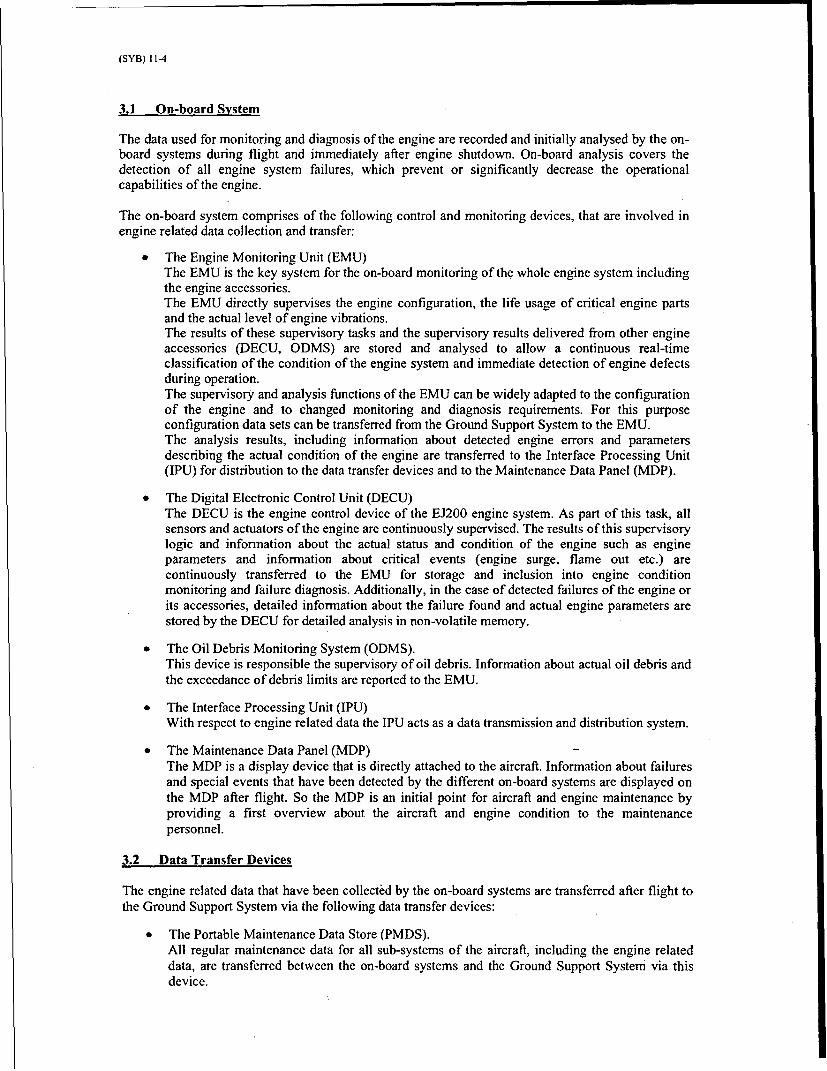
The following figure gives an overview about the fundamental architecture of the Engine HealthMonitoring System:
I- -- ------------------------ --------IEHM Logistics Logistics i
I Life Usage Monitoring H Agent
_ I
i fan iton4-
Vibration Monitoring 4
Incident MonitoringAgnI ,I
Oil System Monitoring -
IFault Isolation (AETS)r -----
IConfiguration of the 5On-I
u ... ~. S i'ste Services SoftwarincludinDatabase) - I
Figure 2: Structure of the EHM System
(SYB) 11-6
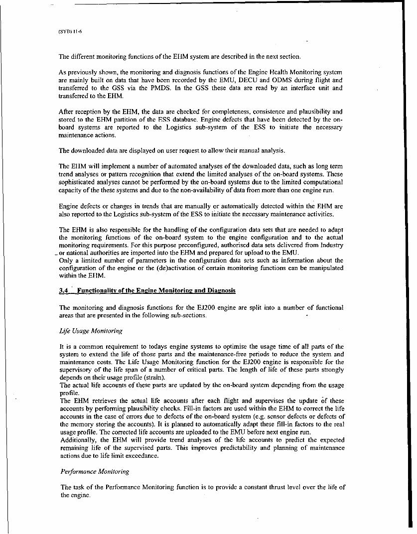
The different monitoring functions of the EHM system are described in the next section.
As previously shown, the monitoring and diagnosis functions of the Engine Health Monitoring systemare mainly built on data that have been recorded by the EMU, DECU and ODMS during flight andtransferred to the GSS via the PMDS. In the GSS these data are read by an interface unit andtransferred to the EHM.
After reception by the EHM, the data are checked for completeness, consistence and plausibility andstored to the EHM partition of the ESS database. Engine defects that have been detected by the on-board systems are reported to the Logistics sub-system of the ESS to initiate the necessarymaintenance actions.
The downloaded data are displayed on user request to allow their manual analysis.
The EHM will implement a number of automated analyses of the downloaded data, such as long termtrend analyses or pattern recognition that extend the limited analyses of the on-board systems. Thesesophisticated analyses cannot be performed by the on-board systems due to the limited computationalcapacity of the these systems and due to the non-availability of data from more than one engine run.
Engine defects or changes in trends that are manually or automatically detected within the EHM arealso reported to the Logistics sub-system of the ESS to initiate the necessary maintenance activities.
The EHM is also responsible for the handling of the configuration data sets that are needed to adaptthe monitoring functions of the on-board system to the engine configuration and to the actualmonitoring requirements. For this purpose preconfigured, authorised data sets delivered from Industryor national authorities are imported into the EHM and prepared for upload to the EMU.Only a limited number of parameters in the configuration data sets such as information about theconfiguration of the engine or the (de)activation of certain monitoring functions can be manipulatedwithin the EHM.
3.4 Functionality of the Engine Monitoring and Diagnosis
The monitoring and diagnosis functions for the EJ200 engine are split into a number of functionalareas that are presented in the following sub-sections.
Life Usage Monitoring
It is a common requirement to todays engine systems to optimise the usage time of all parts of thesystem to extend the life of those parts and the maintenance-free periods to reduce the system andmaintenance costs. The Life Usage Monitoring function for the EJ200 engine is responsible for thesupervisory of the life span of a number of critical parts. The length of life of these parts stronglydepends on their usage profile (strain).The actual life accounts of these parts are updated by the on-board system depending from the usageprofile.The EHM retrieves the actual life accounts after each flight and supervises the update of theseaccounts by performing plausibility checks. Fill-in factors are used within the EHM to correct the lifeaccounts in the case of errors due to defects of the on-board system (e.g. sensor defects or defects ofthe memory storing the accounts). It is planned to automatically adapt these fill-in factors to the realusage profile. The corrected life accounts are uploaded to the EMU before next engine run.Additionally, the EHM will provide trend analyses of the life accounts to predict the expectedremaining life of the supervised parts. This improves predictability and planning of maintenanceactions due to life limit exceedance.
Performance Monitoring
The task of the Performance Monitoring function is to provide a constant thrust level over the life ofthe engine.
(SYB) 11-7
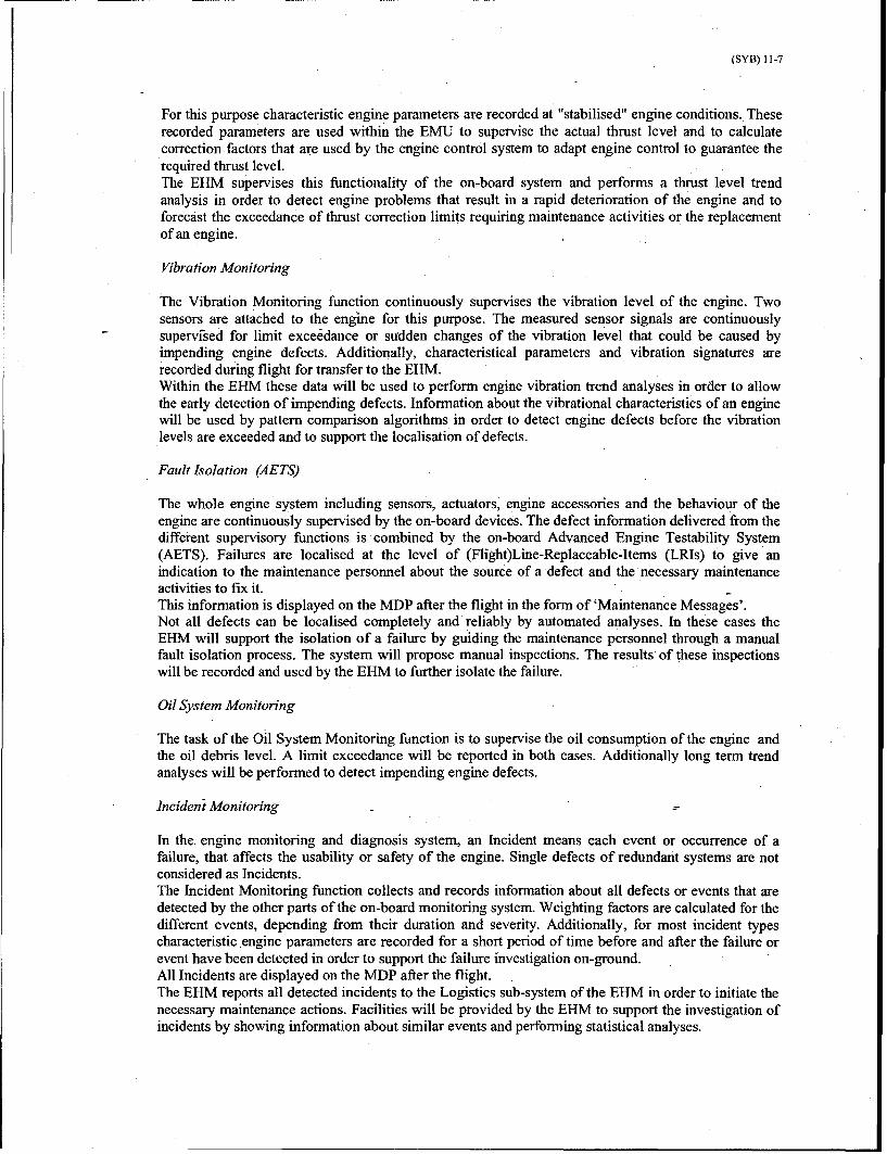
For this purpose characteristic engine parameters are recorded at "stabilised" engine conditions. Theserecorded parameters are used within the EMU to supervise the actual thrust level and to calculatecorrection factors that are used by the engine control system to adapt engine control to guarantee therequired thrust level.The EHM supervises this functionality of the on-board system and performs a thrust level trendanalysis in order to detect engine problems that result in a rapid deterioration of the engine and toforecast the exceedance of thrust correction limits requiring maintenance activities or the replacementof an engine.
Vibration Monitoring
The Vibration Monitoring function continuously supervises the vibration level of the engine. Twosensors are attached to the engine for this purpose. The measured sensor signals are continuouslysupervised for limit exceedance or sudden changes of the vibration level that could be caused byimpending engine defects. Additionally, characteristical parameters and vibration signatures arerecorded during flight for transfer to the EHM.Within the EHM these data will be used to perform engine vibration trend analyses in order to allowthe early detection of impending defects. Information about the vibrational characteristics of an enginewill be used by pattern comparison algorithms in order to detect engine defects before the vibrationlevels are. exceeded and to support the localisation of defects.
Fault Isolation (AETS)
The whole engine system including sensors, actuators, engine accessories and the behaviour of theengine are continuously supervised by the on-board devices. The defect information delivered from thedifferent supervisory functions is combined by the on-board Advanced Engine Testability System(AETS). Failures are localised at the level of (Flight)Line-Replaceable-Items (LRIs) to give anindication to the maintenance personnel about the source of a defect and the necessary maintenanceactivities to fix it.This information is displayed on the MDP after the flight in the form of 'Maintenance Messages'.Not all defects can be localised completely and reliably by automated analyses. In these cases theEHM will support the isolation of a failure by guiding the maintenance personnel through a manualfault isolation process. The system will propose manual inspections. The results of these inspectionswill be recorded and used by the EHM to further isolate the failure.
Oil System Monitoring
The task of the Oil System Monitoring function is to supervise the oil consumption of the engine andthe oil debris level. A limit exceedance will be reported in both cases. Additionally long term trendanalyses will be performed to detect impending engine defects.
Incident Monitoring
In the. engine monitoring and diagnosis system, an Incident means each event or occurrence of afailure, that affects the usability or safety of the engine. Single defects of redundant systems are notconsidered as Incidents.The Incident Monitoring function collects and records information about all defects or events that aredetected by the other parts of the on-board monitoring system. Weighting factors are calculated for thedifferent events, depending from their duration and severity. Additionally, for most incident typescharacteristic engine parameters are recorded for a short period of time before and after the failure orevent have been detected in order to support the failure investigation on-ground.All Incidents are displayed on the MDP after the flight.The EHM reports all detected incidents to the Logistics sub-system of the EHM in order to initiate thenecessary maintenance actions. Facilities will be provided by the EHM to support the investigation ofincidents by showing information about similar events and performing statistical analyses.
(SYB) 11-8
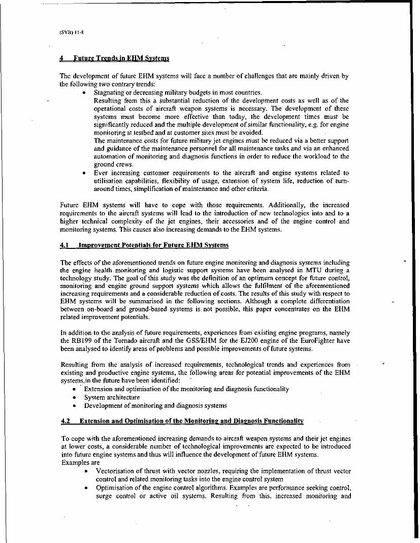
4 Future Trends in EHM Systems
The development of future EHM systems will face a number of challenges that are mainly driven bythe following two contrary trends:
Stagnating or decreasing military budgets in most countries.Resulting from this a substantial reduction of the development costs as well as of theoperational costs of aircraft weapon systems is necessary. The development of thesesystems must become more effective than today, the development times must besignificantly reduced and the multiple development of similar functionality, e.g. for enginemonitoring a( testbed and at customer sites must be avoided.The maintenance costs for future military jet engines must be reduced via a better supportand guidance of the maintenance personnel for all maintenance tasks and via an enhancedautomation of monitoring and diagnosis functions in order to reduce the workload to theground crews,
* Ever increasing customer requirements to the aircraft and engine systems related toutilisation capabilities, flexibility of usage, extension of system life, reduction of turn-around times, simplification of maintenance and other criteria.
Future EHM systems will have to cope with those requirements. Additionally, the increasedrequirements to the aircraft systems will lead to the introduction of new technologies into and to ahigher technical complexity of the jet engines, their accessories and of the engine control andmonitoring systems. This causes also increasing demands to the EHM systems.
4.1 Improvement Potentials for Future EHM Systems
The effects of the aforementioned trends on future engine monitoring and diagnosis systems includingthe engine health monitoring and logistic support systems have been analysed in MTU during atechnology study. The goal of this study was the definition of an optimum concept for future control,monitoring and engine ground support systems which allows the fulfilment of the aforementionedincreasing requirements and a considerable reduction of costs. The results of this study with respect toEHM systems will be summarised in the following sections. Although a complete differentiationbetween on-board and ground-based systems is not possible, this paper concentrates on the EHMrelated improvement potentials.
In addition to the analysis of future requirements, experiences from existing engine programs, namelythe RB199 of the Tornado aircraft and the GSS/EHM for the EJ200 engine of the EuroFighter havebeen analysed to identify areas of problems and possible improvements of future systems.
Resulting from the analysis of increased requirements, technological trends and experiences fromexisting and productive engine systems, the following areas for potential improvements of the EHMsystems-in the future have been identified:
"* Extension and optimisation of the monitoring and diagnosis functionality"* System architecture"* Development of monitoring and diagnosis systems
4.2 Extension and Optimisation of the Monitorin2 and Dialnosis Functionality
To cope with the aforementioned increasing demands to aircraft weapon systems and their jet enginesat lower costs, a considerable number of technological improvements are expected to be introducedinto future engine systems and thus will influence the development of future EHM systems.Examples are
"* Vectorisation of thrust with vector nozzles, requiring the implementation of thrust vectorcontrol and related monitoring tasks into the engine control system
"* Optimisation of the engine control algorithms. Examples are performance seeking control,surge control or active oil systems. Resulting from this, increased monitoring and

(SYB) 11-9
diagnosis requirements are to be fulfilled to ensure the safety and reliability of thosefunctions
* Closer integration of engine control and monitoring, supported by the integration ofmultiple on-board systems into one device. An example is the planned integration oftodays DECU and EMU devices of the EJ200 engine into one device, with the option tointegrate also the ODMS in the future.
The following list gives an overview about possible improvements of the monitoring and diagnosisfunctionality that should be considered for future systems:
* Introduction of expert systems for diagnosis. With these systems the specific knowledge ofengine experts from industry or customer can be made available to all maintenancepersonnel at very -low cost. Experiences made during engine development and duringsolution of problems in the past are automatically used for the solution of actual problems,reducing time and cost of maintenance and increasing the trustworthiness andunderstandability of diagnoses.It should be noted, that expert systems, due to their non-deterministic nature, are not suitedfor on-board monitoring tasks.
* Usage of modem analysis methods such as Bayesian (probabilistic) Networks to identifyfailures sources and neural networks to recognise characteristical patterns within aircraftsignals (e.g. recorded vibration signatures)
* Thrust Monitoring (in conjunction with performance seeking control)* Surge detection and control* Detection of FOD and bird strike via inlet sensors or engine distress monitoring* Detection of cable defects* Active oil systems* Re-calculation of life accounts after changes of lifing algorithms or of their parameters* Earlier detection of defects via improved trend analyses
Many of these functions are built on very complex algorithms and large amounts of data and must bewidely configurable. Therefore most of these algorithms can be executed on ground only. Thisrequires the storage and transmission of large amounts of data by the on-board systems. Futuresystems will therefore have to support the continuous storage of relevant parameters during the wholeflight and the transmission of these data to the GSS/EHM, where they will be stored for the whole lifeof an engine.
4.3 System Architecture (Inteerated Monitorine and Ground Support System)
The flexibility and commonality of the actual EHM system is limited due to the following problems:a The EHM is inseparably integrated into the health monitoring system of the aircraft. Parts of
the engine related functionality and all basic functions and interfaces to the outside world areimplemented by othei-ESS sub-systems.Thus a further development of the EHM strongly depends from modifications of other ESSsub-systems, resulting to high modification costs. Porting of on-board and off-board parts ofthe engine monitoring and diagnosis system due to the usage of the same engine in otheraircraft systems requires a redevelopment of the EHM system.Another problem resulting from the distribution of the engine related functionality over anumber of ESS sub-systems is, that the ensuring of the fulfilment of all requirements related toengine monitoring, diagnosis and maintenance is very complicated. There is a considerablerisk, that functionality will be missed or duplicated in the completed ESS system, because theresponsibilities for these functions are unclear.
0 The complexity of the on-board system is too high.In the EuroFighter five on-board devices contribute to the collection and transfer of enginerelated data, which are distributed over 3 transfer devices. This causes high technical effort,high expenses and complicated co-ordination. Modifications and extensions of the on-boardsystem affect a lot of devices. This and the technical complexity of the system makemodifications complicated, expensive and risky due to possible side-effects.

(SYB) I 1-10
Engine data are transferred using the same transfer devices as aircraft data.The capacity of those systems is limited, all on-board systems compete for the storage space.The number of devices involved in engine data transfer is too high. Thus adaptations oftransferred engine data to future requirements are nearly impossible, again expensive and timeconsuming.
All off these hindrances prevent the development of a really flexible, fully integrated enginemonitoring, diagnosis and ground support system, that is easily adaptable to the ever-changingtechnological needs and customer requirements. The fulfilment of the requirements is significantlycomplicated, expensive and time consuming with the current system architecture and concepts.
Therefore the following improvements should be considered for future systems:"* Thorough integration of all engine related monitoring and diagnosis tasks into the EHM"* Standardised interfaces to the l6gistic system"* Usage of a dedicated engine data transfer medium
4.3.1 Thorough Integration of all Engine Monitoring and Diagnosis Tasks into the EHM
An essential condition to ensure the flexibility of future EHM systems and their adaptability todifferent requirements and aircrafts is the integration of all engine related monitoring and diagnosistasks into the EHM.
There is a number of engine related functions in the ESS for the EuroFighter, that are not in theresponsibility of the EHM:
4 The Maintenance messages that are created on-board by the AETS function of the EMUare initially handled by the Aircraft System Health (ASH) sub-system of the ESS. Thecorresponding maintenance activities are initiated by the ASH system before the messagesare passed to the EHM for further handling and analysis.
CodedCoded Maintenance
u DelS MaiAntenance M i e
logiticssub-yste. MessEH hanesH ath life accontsoI rtclprsta r
Action Edcainttes
Maintenadce
Action Identitier s a-y tem.
daM Logi st sticsAction
Figure 3: Transfer of Information related to AETS Maintenance Messages in the ESS
0 The handling of the life accounts of engine parts is split between the EHM and the -logistics sub-system. The EHM' handles the life accounts of the critical parts that aresupervised by the EMU, the accounts for all other life limited parts are handled by thelogistics sub-system.
* Experience capturing functionality will be provided by the Experience Capturing systemof the ESS. Although this functionality requires an in depth knowledge about the enginesystem, it is planned to implement this into another sub-system.
The aforementioned examples of a problematic distribution of engine relatedfrmnctionalities over different sub-systems result to the following weaknesses duringdevelopment and advancement of EHM systems:
"* The system design becomes unnecessarily complex."* A number of additional interfaces have to be introduced between sub-systems."* The development of the whole ESS is considerably complicated'due to the high
co-ordination effort that is needed to ensure, that all related functionality isprovided and that no functionality is implemented twice.
(SYB) I1-11
* The development of distributed functionalities cannot be started before the lastinvolved party starts with the development, resulting in a high program risk to theother parties.
* A porting of EHM systems with this distribution of functionality means in fact acomplete re-development.
4.3.2 Standardised Interfaces to the Logistic System
From customers point of view only an integrated monitoring, diagnosis and logistic support system forthe whole aircraft weapon system is thinkable, a differentiation between different systems for aircraftrelated tasks and engine related tasks is not acceptable.There must be a common, uniform and consistent user interface. Therefore the integration ofmaintenance management tasks into the EHM is not possible since it would lead to two different userinterfaces for aircraft and engine mainitenance. Instead of this the EHM must be seamlessly integratedinto the aircraft maintenance system. All engine defects must be reported to the central maintenancemanagement system for the whole aircraft system, all EHM functionalities must be callable from thelogistics sub-system.
This can be ensured in an effective and flexible way only, if there is a standardised interface to thelogistics system. The specification of this interface must include features that allow the EHM to
* initiate maintenance activities after engine defects have been detected* handle call-backs from the logistics sub-system to support the fault investigation and to
provide engine specific maintenance guidance.* to get back information about completed maintenance activitieso get information about the aircraft configuration.
The development of such an interface, that allows flexible adaptations to special needs of a concrete
system is supported by todays software component architectures.
4.3.3 Usage of a dedicated engine data transfer medium
A dedicated engine data transfer module (Portable Engine Data Store - PEDS) should be used forengine data instead of sharing the same transfer media for engine and aircraft data
A number of problems resulting from this shared usage of the data transfer devices for engine andaircraft data could be solved by the usage of such a device:
"* The on-board system would become significantly less complex due the avoidance ofadditional interfaces for engine data transfer and of engine data processing capabilities thatmust be implemented otherwise into a number of devices just to handle the transfer of-ngine related data.
"* Within the ESS, the engine data could be read directly by-the EHM instead of their readingand decoding by another ESS system, splitting them from the aircraft data andtransmission to the EHM, where they can be handled.
"* The development of the engine transfer medium in the responsibility of the enginemanufacturer would ensure, that the needs of the engine system related to data transfer arefully met.
" The development of engine data transfer mechanisms could be undertaken independentlyfrom the development of the mechanisms for aircraft data transfer.
"* Changes in the transferred data would be significantly less complicated due to the smallernumber of involved systems and manufacturers.
"* A porting of the engine monitoring, diagnosis and ground support system would besignificantly easier, because the same PEDS module could be used for different aircrafttypes. Additionally, a PEDS would allow the design of a complete fully integrated systemof on-board devices, transfer media and ground support components
(SYB) 11-12
To avoid the implementation of an additional data transfer device into the aircraft, the PEDS shouldnot be realised as a separate device. Instead of this, it should be a memory module that can easily beintegrated into the aircraft data transfer devices.The storage capacity of the PEDS should be large enough to allow the continuous recording of engineparameters with a resolution that is sufficient for ground based monitoring and diagnosisfunctionalities. In this case the BSD would no longer be needed for engine data recording, anotherdevice and a set of interfaces would become obsolete. Additionally, a complete data recording andarchiving over the whole life of the engine would be possible. This is not the case today, because theBSD must be shared between aircraft and engine data.
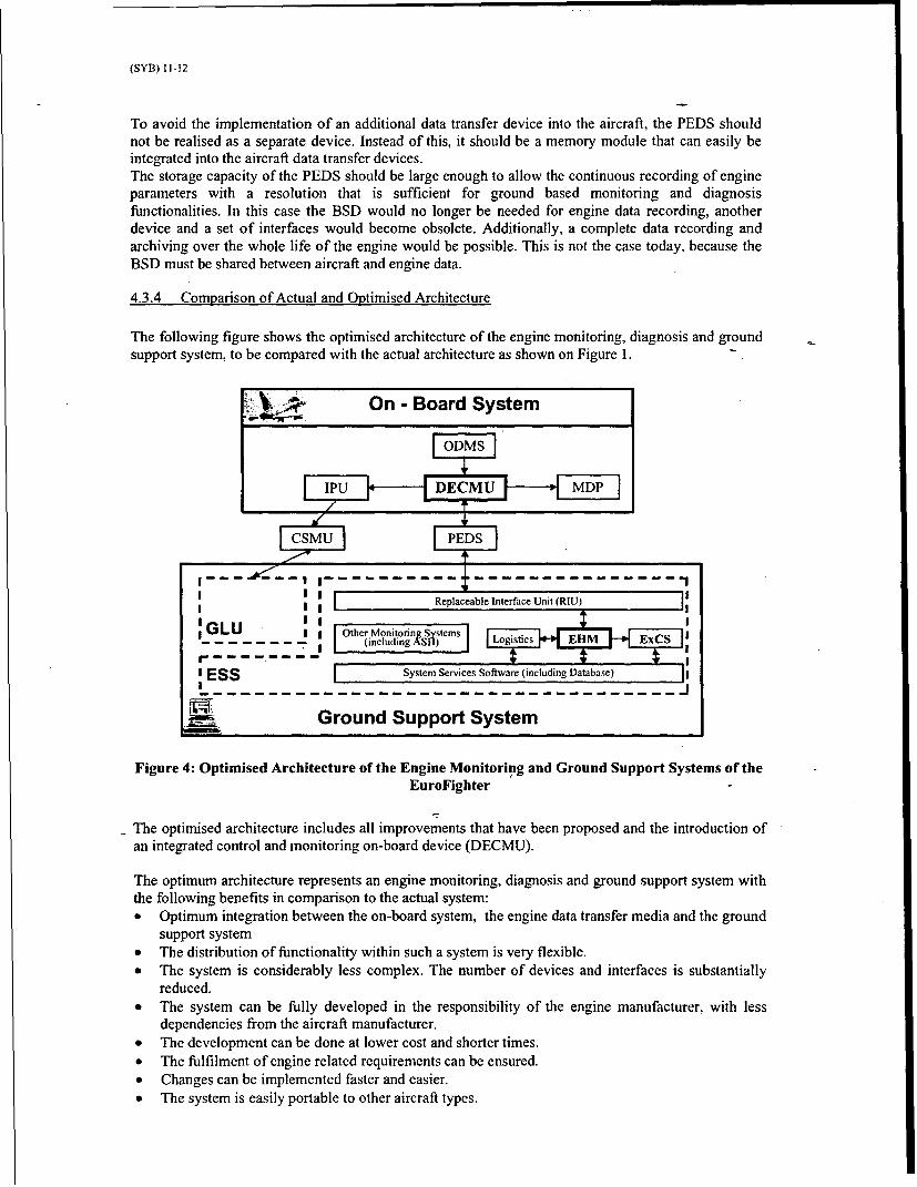
4.3.4 Comparison of Actual and Optimised Architecture
The following figure shows the optimised architecture of the engine monitoring, diagnosis and groundsupport system, to be compared with the actual architecture as shown on Figure 1.
SOn - Board System
----'---- - -- ------------------ - ---------- - ---I Ii I
Replaceable Interface Unit (RIU)
IL I Other MonitorinN SstemsGLU - - - -- e- (including Logistics E
11 ESS ISystem Services Software (including DaaaEl
Ground Support System
Figure 4: Optimised Architecture of the Engine Monitoring and Ground Support Systems of theEuroFighter
- The optimised architecture includes all improvements that have been proposed and the introduction ofan integrated control and monitoring on-board device (DECMU).
The optimum architecture represents an engine monitoring, diagnosis and ground support system withthe following benefits in comparison to the actual system:"* Optimum integration between the on-board system, the engine data transfer media and the ground
support system"* The distribution of functionality within such a system is very flexible."* The system is considerably less complex. The number of devices and interfaces is substantially
reduced."* The system can be fully developed in the responsibility of the engine manufacturer, with less
dependencies from the aircraft manufacturer."* The development can be done at lower cost and shorter times."* The fulfilment of engine related requirements can be ensured."* Changes can be implemented faster and easier."* The system is easily portable to other aircraft types.
(SYB) 11-13
4.4 Development of MonitorinQ and Diagnosis Systems
Beside the extension of the monitoring and diagnosis functionality and a better structured systemarchitecture, potential for improvements of future EHM systems and for cost and development timereductions also lies in the development process of the system.
A better integration with development support systems and with other logistic support systems forother maintenance tasks beside the flight line maintenance should be aspired to provide a better reusepotential for developed system parts.A number of systems with similar tasks as the EHM is needed for development, production and repairof the engine:
* Monitoring and set-up units to support the development of the control and monitoring systemhard- and software
* Systems for monitoring, diagnosis and engineering data transfer and analysis at the enginetestbed during development, certification and production pass-off tests
* Data transfer and analysis systems to be used at higher maintenance levels, e.g. enginerepair&overhaul at customer and industry sites.
Currently, separate systems with similar functionalities are developed for the different stages of theproduct lifecycle.
An earlier design and development of the EHM, parallel with the on-board and data transfer parts ofthe engine monitoring and diagnosis system would significantly reduce the development risk.Todays EHM systems are usually developed after the design of the on-board monitoring, control anddiagnosis system and of the data transfer devices has been finalised.So the EHM system has to deal with and to make the best use of the realities of the given systems, anoptimisation of the on-board and transfer components to the needs of the ground based system is eithernot possible or requires a huge effort to modify these systems.This causes additional effort in EHM system development as well as limitations to the functionalitiesof the ground based system.
To solve both problems, the development of future EHM systems should be done in parallel to thedevelopment of the on-board and of the data transfer systems. Parts developed for the EHM should beused already during development to support similar tasks. This would avoid the multiple developmentof similar systems for the different stages of the development cycle and for the operational phase ofthe system.
Additionally, really integrated and coherent engine monitoring, diagnosis and ground support systemscould be developed. The usage of identical systems would improve the compatibility betweencustomer and industry systems, i.e. between the EHM and the industry systems for repair&overhaul.
Integration and coherence could be fully validated during the different development phases, the EHMwould be validated together with the other parts of the system. This would significantly improve thematurity of the whole system before the operational phase.
5 Summary and Conelusions
The EJ200 EHM will be a modern, state-of-the-art engine health monitoring system with acomprehensive and sophisticated monitoring and diagnosis functionality that provides extensiveengine maintenance support and guidance to the ground crew. The EHM system will be seamlesslyintegrated into the overall Ground Support System for the EuroFighter.
However, continuous improvements of EHM systems are required to ensure that future EHM systemswill meet the challenges resulting from the ever-increasing complexity of the engine system and due tocontinuously rising customer requirements that are to be fulfilled at lower cost.

(SYB) 11-14
Improvement potential has been identified in the following areas:"* Extension and optimisation of the monitoring and diagnosis functionality"* EHM System architecture
"• Thorough integration of all engine related monitoring and diagnosis tasks into the EHM"* Standardised interfaces to the logistic system"* Usage of a dedicated engine data transfer medium
"* Development of monitoring and diagnosis systems"* A better integration with development support systems and with other logistic support
systems outside the flight line maintenance"* Earlier development of the EHM, parallel with the on-board and data transfer parts of the
engine monitoring and diagnosis system.
These improvements result to a number of benefits:"* Improved monitoring and diagnosis of engine defects"* Reduced complexity of the engine monitoring, diagnosis and ground support system"* Improved portability and modifiability of EHM systems"* Reduced development time and cost.

(SYB) 11-15
Paper 11: Discussion
Question from L Jaw - Scientific Monitoring Inc, USA
Can you describe what you meant by an 'active oil system'?
Presenter's Reply
Preliminary thought on this is to utilise valves to control oil temperature and quantity, in order tomatch them to the requirements of specific engine operating conditions.


![[Aviation] Eurofighter Typhoon](https://img.dokumen.tips/doc/110x75/55721303497959fc0b9169b6/aviation-eurofighter-typhoon-55c804730893c.jpg)


