Embed Size (px)
Citation preview

Tehnički vjesnik 25, Suppl. 1(2018), 157-164 157
ISSN 1330-3651 (Print), ISSN 1848-6339 (Online) https://doi.org/10.17559/TV-20180111132233 Original scietific paper
Decreasing Harmonics via Three Phase Parallel Active Power Filter Using Online Adaptive Harmonic Injection Algorithm
Ömer Ali KARAMAN, Faruk ERKEN, Mehmet CEBECİ
Abstract: Three-Phase Parallel Active Power Filter (PAPF) control mechanism via a novel Adaptive Harmonic Injection (AHI) algorithm is proposed in order to filter out harmonics generated by non-linear loads and carry out reactive power compensation. The presented PAPF mechanism is composed of two stages. Before is the extraction of reference current to determine currents with harmonics. Once the reference current is determined, according to the reference current, appropriate current harmonics are injected by triggering of the inverter switches. The proper amplitude and phase values of the harmonics that will be injected are estimated online at any instant by the AHI algorithm. In this study, the sine and the cosine of the phase angle for any harmonic order is weighted by the values estimated via the AHI algorithm, thus obtaining harmonic orders at the desired amplitude and phase. Simulations are performed using various non-linear loads in order to validate the proposed method. Keywords: adaptive algorithms; Parallel Active Power Filter; power quality; power system harmonics; total harmonic distortion
1 INTRODUCTION
Although grid voltage varies sinusoidally, loads that contain thyristor or diode rectifiers draw significant amounts of harmonic currents from the grid. These harmonic currents cause harmonic voltage drops in system impedance, leading to voltage distortions at the point of common coupling. This distortion in voltage affects other receivers at the same distribution level. Hence, the harmonic suppression is very important in today’s distribution power systems [1, 2].
Acceptable limits for voltage and current harmonics in the grid are recommended by IEEE-519-1992 standards where Total Harmonic Distortion (THD %) value is determined as 5% for the current and 3% for the voltage [3]. In order to meet these requirements and maintain electrical power quality at an acceptable range, active power filters are widely used. Parallel active power filters are the most widely used type of active power filters in the industry [4, 5]. The most important objective for the use of parallel active power filters is to overcome load current harmonics. In addition, reactive power compensation and three-phase current balancing are also carried out [6]. The general structure of voltage source PAPF is shown in Fig. 1.
AC Grid
InverterControllerInputs
Supply impedance
Nonlinear Load
Figure 1 Voltage source PAPF
The basic principle of PAPF is to inject currents in
reverse phase and equal magnitude to the grid in order to eliminate the harmonics of load current and to perform reactive power compensation. Thus, harmonics are eliminated and the source current oscillates sinusoidally.
Hence, the harmonic components drawn by the load currents should be determined. It is important to extract the correct value of the reference current for successful application of PAPF. Different reference current extraction methods in the literature are summarized in Fig. 2. Among these methods, time domain and frequency domain based approaches are the most commonly used ones [7].
Active Power System Filters
Current/Voltage reference Synthesis
Highpass filter method
Lowpass filter method
Current/Voltage reference calculation
Time domain
Frequency domain
Other algorithms
Instant reactive powerSynchronous detection Constant power factor Synchronous frameSynchronous flux detection
Conventional Fourier and FFT
Constant active powerFictitious power compensation
Sine multiplication
Modified Fourier series
Figure 2 Reference Current/Voltage extraction methods
Although different reference current extraction
methods have their own limitations, most of them operate stable under constant loads. However, their performance is affected significantly under varying load conditions. Different approaches are proposed in the literature, in order to mitigate their performance under varying load conditions.
For instance, in artificial neural networks based reference current extraction methods, a lot of data is required to train the network [8]. Similarly, calculations are cumbersome and take too much time in Fourier transformation based methods [4]. Some authors have suggested algorithms based on least mean square (LMS). Badoni et al., propose a least squares based PAPF for harmonic compensation, power factor correction, load balancing and voltage regulation [9]. In [10], least squares method is compared with the Wiener filter approach in terms of their reactive power resolution and other power quality measures. In [11], a parallel PAPF structure composed of different filter types is utilized instead of a single PAPF, so that, a more reliable and a flexible filtering is achieved. The method proposed in [12] makes use of inverter DC link voltage where the DC link voltage is decreased without sacrificing from the compensation ability of the active filter.
Ömer Ali KARAMAN et al.: Decreasing Harmonics via Three Phase Parallel Active Power Filter Using Online Adaptive Harmonic Injection Algorithm
158 Technical Gazette 25, Suppl. 1(2018), 157-164
In this study, a normalized least mean square method based AHI algorithm is used as the reference current extraction method. The proposed AHI algorithm rapidly and accurately estimates proper amplitude and phase values of to-be-injected harmonic orders in an online manner. Estimated current harmonics values are re-injected to the grid with an opposite phase and amplitude, thus minimizing the current harmonics. The AHI algorithm keeps track of the changes in load operating characteristics and adapts itself accordingly. This method was previously applied successfully on a controller board. It was shown that, the method may be used as a computationally efficient torque ripple reduction mechanism in permanent magnet synchronous motor [13]. Different control methods are used to generate the switching signals according to the acquired reference current. The PWM, hysteresis, sliding mode or fuzzy based methods are widely used [4]. Hysteresis band current controller (HBCC) is used in this study. HBCC is a popular controlling method due to its simplicity and fast implementation. HBCC is a non-linear current controlling method which ensures that the output current of the inverter stays inside a certain band interval thus directly controlling the current [14, 15]. Reference current is compared with the actual current, in the proposed method, and inverter switching signals are generated according to the acquired current error. 2 ADAPTIVE HARMONIC INJECTION (AHI) ALGORITHM
An overview of current harmonic analysis and limitations along with the Adaptive Harmonic Injection (AHI) Algorithm are presented in the sequel. 2.1 Current Harmonic Analysis and Limitations
Harmonics are defined as sine components of a periodic wave with frequencies at multiples of the fundamental frequency [16]. The total harmonic distortion (THD) of a signal is defined as the ratio of sum of powers of all harmonic components to the power of the fundamental frequency [4]. Harmonic Distortion can be viewed as the difference of a signal from an ideal sine wave. THD for current can be expressed as:
2
1 1100 sh
h s
ITHDi I≠
= ⋅ ∑
(1)
where, Ish are the current harmonics. Non-linear loads (rectifiers, inverters, AC regulators etc.) draw non-linear current from the grid in electrical systems. Power electronic based equipment such as motor drivers, switched power sources, alternative current (AC)/direct current (DC) converters are frequently used in recent years, due to technological advancements. This equipment are loads with non-linear properties. The controlled or uncontrolled switching operations required for them yield a non-linear operating characteristic. These loads have negative impacts on the voltage and current signals of the grid they feed on and decrease the energy quality by drawing non-linear currents. These non-linear currents generate voltage harmonics in the power systems and the generated voltage
harmonics spread out over the entire power system, thus affecting all elements of the system. In addition, current and voltage harmonics result in overheating of the transformers, increase in losses, decrease in the power factor and efficiency of the system. In addition to the aforementioned power quality issues, reactive power is also drawn from the grid and harmonics start to be generated as the signal form of the current drawn from the grid diverts from the sinusoidal nature. Whereas 3 and multiples of 3rd harmonics are observed to be dominant in single-phased loads; 5th, 7th and 11th order harmonics are observed in three-phased loads [19]. Various limitations are recommended in order to protect the power systems and devices against harmonics. These limitations declared by IEEE and IEC are accepted as harmonic standards in many countries around the world.
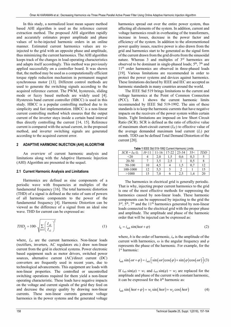
The IEEE Std 519 brings limitations to the current and voltage harmonics at the Point of Common Connection (PCC). Tab. 1 shows the current harmonic limits recommended by IEEE Std 519-1992. The aim of these standards is to keep the harmonic currents that have negative impacts on the receivers of the power system within certain limits. Tight limitations are imposed on low Short Circuit Ratio (SCR). SCR is defined as the ratio of effective value of maximum short-circuit current (ISC) to effective value of the average demanded maximum load current (IL) per month. TDD can be defined Total Demand Distortion of the current [20].
Table 1 IEEE Std 519-1992 Current Harmonic Limits SCR = ISC/IL H<11 11-16 17-22 23-34 35< TDD
<20 4 2,0 1,5 0,6 0,3 5 20-50 7 3,5 2,5 1 0,5 8 50-100 10 4,5 4 1,5 0,7 12
100-1000 12 5,5 5 2 1 15 >1000 15 7,0 6 2,5 1,4 20
The harmonics in electrical grid is generally periodic.
That is why, injecting proper current harmonics to the grid is one of the most effective methods for suppressing the harmonics caused by non-linear loads. These harmonic components can be suppressed by injecting to the grid the 3rd, 5th, 7th and the 11th harmonics generated by non-linear loads connected to the electrical grid with the proper phase and amplitude. The amplitude and phase of the harmonic order that will be injected can be expressed as:
sin( )h mhi i h tω ϕ= + (2) where, h is the order of harmonic, im is the amplitude of the current with harmonics, ω is the angular frequency and φ represents the phase of the harmonic. For example, for the 1st harmonic:
( ) ( ) ( ) ( ) ( )sin sin cos sin cosmh mhi t i t tωϕ ϕ ϕω ω + = + (3) If imh sin(φ) = w1 and imh sin(φ) = w2 are replaced for the amplitude and phase of the current with constant harmonic, it can be expressed for the hth harmonic as:
( ) ( ) ( )1 2sin sin cosmhi h t w h t w h tω ϕ ω ω+ = + (4)

Ömer Ali KARAMAN et al.: Decreasing Harmonics via Three Phase Parallel Active Power Filter Using Online Adaptive Harmonic Injection Algorithm
Tehnički vjesnik 25, Suppl. 1(2018), 157-164 159
As can be seen, a harmonic with the desired amplitude and phase can be obtained if the sine and cosine of the phase angle for any given harmonics are scaled by proper values. These proper values are called as weights and denoted by w, and the Adaptive Harmonic Injection (AHI) algorithm is used to determine the weights [12]. 2.2 AHI Algorithm
AHI algorithm is a novel technique comprised of more
than one sub-value and depending on the combination of data from the input which operates linearly. This is an algorithm which was applied successfully in various image processings and computer vision problems, and wireless communication applications [19-21]. This algorithm was also successfully applied in reducing the moment fluctuations in motors. Sub-values or inputs are combined linearly using updated weights with an Adaptive Data/Decision Fusion (ADF) method that is based on making projections on convex sets that define sub-values in an online manner [12].
This method is based on the principle of injecting a harmonic with the desired magnitude to the system in order to decrease harmonics. The proper amplitude and phase values of the harmonics to be injected are estimated in an online fashion at each instant of time. Adaptive Harmonic Injection (AHI) algorithm is used to determine weight values of each harmonic for injecting harmonics at the proper amplitude and phase. The harmonic orders to be injected are determined in advance using the proposed AHI method. Sine and cosine values of each harmonic phase angle are scaled by corresponding weights and linearly combined [12].
As can be seen in Fig. 3, the difference between load current and filter current is estimated to determine the error term.
1
2
1
+-
sin
cos
AHI
sin
cos
sin
cos
Memory
Error w(n+1)
y(n+1)Weights
+-
3
w(n)
Figure 3 Block Diagram of Adaptive Harmonic Injection Algorithm
This difference is not used directly as the error term.
The error term is obtained by subtracting the current value from the previous value. The weight values are updated in an online manner depending on the increase and decrease in error values. 2.3 Weight Update Mechanism
Let us assume that the combined algorithm is comprised of N sub-inputs (harmonics); H1, H2,…, HN. Each sub-input at the time step – n generates an input value with an average of zero (H(x,n) ∈ R) for a sample x input.
Let us define the expression ( ) ( ) ( ) T1, , ,NH x n H x n H x n = …
as the vector of the value of the sub-inputs at the nth time step for the input x and ( ) ( ) ( ) T
1, , ,Mw x n w x n w x n = … as the weight vector at that instant. We define the estimated y(x,n) value as follows: ( ) ( ) ( ) ( ) ( )Tˆ , , ,i i
iy x n H x n w n w n H x n= = ∑ (5)
The difference between the desired y(x,n) and
estimated value ( )ˆ ,y x n is defined as the error of the system: ( ) ( ) ( ), , ˆ ,e x n y x n y x n= − the weight vector values are updated by minimizing the mean square error (MSE).
( ) ( )( )2min , , , ,ˆ 1,wi
y x n y x n i N − = … (6)
where, E denotes the expectation operator. If the expression is derived with respect to weight:
( ) ( )( ) ( )
( ) ( )( )2 , , ,
2 , , , 1,..
ˆ
.,
i
i
E E y x n y x n H x nw
E e x n H x n i N
∂ = − − = ∂= − =
(7)
And if the expression is equated to zero;
( ) ( )( )2 , , 0, 1, ,iE e x n H x n i N− = = … (8) N – many equations are obtained. The solution of these equations is called the Wiener Solution. However, the solution to the following equation is obtained by using the gradient in Eq. (7) inside an optimization algorithm, known as the steepest descent algorithm, for obtaining a repeating solution for the minimization problem (6); ( ) ( ) ( ) ( )1 , , , 1,iw n w n E e x n H x n i Nλ + = + = … (9)
where, λ is the step size. Instead of the expectation values, instantaneous values are used in (9): ( ) ( ) ( ) ( )1 , ,iw n w n e x n H x nλ+ = + (10)
The following can be written instead of the step size λ,
in Eq. (10):
2,Hx n
µλ = (11)
Hence, the following equation is obtained, which is
also known as the Normalized Least Mean Squares Method (NLMS):
( ) ( ) ( )( )
( )2
,1 ,
,
e x nw n w n H x n
H x nµ+ = + (12)

Ömer Ali KARAMAN et al.: Decreasing Harmonics via Three Phase Parallel Active Power Filter Using Online Adaptive Harmonic Injection Algorithm
160 Technical Gazette 25, Suppl. 1(2018), 157-164
Weights of the harmonics are updated according to Eq. (12). Here, μ is the update parameter and the NLMS algorithm converges to the Wiener solution for 0<μ<2 [19]. 3 ADAPTIVE HARMONIC INJECTION (AHI) ALGORITHM 3.1 Harmonic Power and Current (Power and Current with
Harmonic)
If the grid is assumed that the pure, in other words doesn’t have harmonics, the grid voltage is in the ideal form and can be expressed by the Eq. (13).
( ) sins mV t V tω= (13)
If it is assumed that this grid feeds a non-linear load, the general expression of the current drawn from the grid is given by Eq. (14). This current equation includes both the fundamental current component and infinite number of harmonics. This current can be expressed as:
( ) ( )
( ) ( )
1
12
sin
sin sin
nm nn
m nm nn
i t I n t
I t I n t
ω ϕ
ω ϕ ω ϕ
∞
=∞
=
= + =
= + + +
∑
∑ (14)
In the equation the fundamental component is the
maximum value of first order harmonic Im is also the maximum value of the load current. The sign of the phase angle φ1 of the load is written as a general expression independent of the inductive or capacitive load condition. The instantaneous power drawn from the grid can be expressed as: ( ) ( ) ( )sp t V t i t= ⋅ (15)
If the Eq. (13) and Eq. (14) are placed in Eq. (15), the
following power components are obtained: ( )
( )
21
1
2
sin coscos sin sin
sin sin
m m
m m
m nm nn
p t V I tV I t t
V t I n t
ω ϕ
ω ω ϕ
ω ω ϕ∞
=
⋅
= ⋅ ⋅ +
+ ⋅
⋅
⋅
+
+
⋅ ⋅
−∑
(16)
As can be seen from Eq. (16), active power in addition reactive power and infinite number of harmonics are drawn from the grid. If it is separated active power in Eq. (16)
2active 1sin cosm mP V I tω ϕ= ⋅ (17)
If it is withdrawn from the active power the
instantaneous power value expressed by Eq. (16) the reactive and harmonic power components are acquired. Similarly, in Eq. (14), if the real current is subtracted from the total current the harmonic and reactive current components are obtained. Fig. 4 shows the block diagram of PAPF comprised AHI algorithm.
Figure 4 PAPF Block Diagram with AHI Algorithm
3.2 Reactive Power Compensation
Reactive power is used some electrical equipment that uses a magnetic field, such as motors, generators and transformers. The reactive power demand causes unnecessary current circulation in the grid. Generating reactive power at a point closer to the load has many advantages in power generation, transmission and distribution system. These advantages can be summarized as the increase of the power capacity of the grid, decrease in heat losses with decreasing current as well as decrease in harmonics.
PAPF is generally used to decrease the currents harmonics and for reactive power compensation [22]. Proposed PAPF method provides fast and dynamic reactive power compensation even under varying load conditions. Both current harmonics and reactive current are estimated online via AHI algorithm as shown in Figure 4. 3.3 Hysteresis Band Current Controller (HBBC)
In this study switching signals are obtained by using Hysteresis Band Current Controller (HBCC) as a control method. Hysteresis Band Current Controller (HBCC) is proven that it is an effective method for generating gate signals in all applications of active power filters with voltage source inverters. In addition, this is a consistent and fast method with a high accuracy rate [13]. It is a control method in which reference compensation current and actual compensation current are combined on a hysteresis band to generate switching signals. HBCC is a non-linear current controlling method which ensures that the output current of the inverter keeps tracking within a certain band. Output currents and reference currents are compared in order to control the current at the inverter output. The acquired error signals are applied to the hysteresis controllers to generate switching signals. As can be seen in Fig. 5, S2 switch starts conducting when the error signal reaches the upper limit of the hysteresis band thus decreasing the current, whereas S1 switch starts conducting when the error signal reaches the lower limit of the hysteresis band thus increasing the current.
In this study, reference currents are compared with the inverter output currents and the obtained error signals are applied to the HBCC as input signals. The required gate signals are generated via HBCC which are required to track the reference values of the inverter currents. Since two-level inverter is used in the simulation study, totally 6 gate signals are needed.

Ömer Ali KARAMAN et al.: Decreasing Harmonics via Three Phase Parallel Active Power Filter Using Online Adaptive Harmonic Injection Algorithm
Tehnički vjesnik 25, Suppl. 1(2018), 157-164 161
Figure 5 PAPF Block Diagram with AHI Algorithm
4 SIMULATION RESULTS FOR PAPF WITH AHI
ALGORITHM
In this study, the block diagram of the 3-phase, 3-wired two-level voltage source inverter based PAPF is given in Fig. 6. As can be seen from the figure, PAPF is comprised of a three-phased grid, an inverter, a connection inductance to connect the inverter to the grid, non-linear loads, AHI algorithm for detecting the current harmonics and a controlling unit for controlling the inverter current.
Non-linear LoadsAC Grid Supply impedances
Coupling inductors
IS IL
IF
AH
I A
lgor
ithm
HB
AD
IL_abc
IF_abc
Phase anglePWM
Generation
g
Figure 6 Block Diagram for PAPF with AHI Algorithm
To obtain the non-linear loads, 6 pulse bridge diode
rectifier that feeds the R-L load is used to generate the harmonic currents as shown in Fig. 7.
Figure 7 R-L Load with Diode Rectifier
Load parameters are shown in Tab. 2.
Table 2 Load Parameters
Load Parameters
Resistance (R) Inductance (L) Capacıtance (C)
Load-1 10 Ω 15 mH Load-2 15 Ω 25 mH Load-3 20 Ω 20 mH and 5µF
Wave form for the three phases of the current drawn
by non-linear loads and FFT analysis are shown in Fig. 8. As can be seen from Fig. 8, the current wave form drawn
from the grid as a result of the non-linear characteristics of the loads is not sinusoidal when PAPF is disabled and that the THD% is 20,61.
a)
b)
c)
d)
Figure 8 Load-1 simulation results: a - Currents drawn by non-linear loads from the grid (PAPF disabled), b - FFT of the currents drawn by non-linear loads
(PAPF disabled), c - Currents drawn by non-linear loads from the grid (PAPF enabled) and d - FFT of the currents drawn by non-linear loads (PAPF enabled)
As can be seen in Fig. 8a THD% is much higher than
the 5% value recommended in the IEEE-519 standards. Whereas the currents drawn by non-linear loads have transformed into pure sinusoidal when PAPF is enabled, THD% decreased to 1,92%. This THD% value is observed to be much less than the 5% value recommended in the IEEE-519 standards.
0 0.005 0.01 0.015 0.02 0.025 0.03 0.035 0.04 0.045 0.05
t (s)
-50
-40
-30
-20
-10
0
10
20
30
40
50
Load
Cur
rent
s IL
(A
)
Fundamental (50Hz) = 45.79 , THD= 20.61%
0 2 4 6 8 10 12 14 16 18 20
Harmonic order
0
5
10
15
20
25
30
35
40
45
Mag
0.2 0.205 0.21 0.215 0.22 0.225 0.23 0.235 0.24 0.245 0.25
t (s)
-50
-40
-30
-20
-10
0
10
20
30
40
50
So
urc
e C
urr
en
ts I
S (
A)
Fundamental (50Hz) = 45.53 , THD= 1.92%
0 2 4 6 8 10 12 14 16 18 20
Harmonic order
0
5
10
15
20
25
30
35
40
45
Mag

Ömer Ali KARAMAN et al.: Decreasing Harmonics via Three Phase Parallel Active Power Filter Using Online Adaptive Harmonic Injection Algorithm
162 Technical Gazette 25, Suppl. 1(2018), 157-164
Waveform and FFT analysis of the currents drawn by non-linear loads when loaded with Load-2 is shown in Fig. 9. As can be seen from Fig. 9, the current waveform drawn from the grid by loads as a result of their non-linear characteristics is not sinusoidal and that THD% is 17,71%. This value is much higher than 5% value recommended in IEEE-519 standards. Whereas the currents drawn by non-linear loads transformed into pure sinusoidal when PAPF with AHI algorithm enabled, THD% decreased to 1,53%. This THD% value is observed to be much less than 5% value recommended in the IEEE-519 standards.
a)
b)
c)
d)
Figure 9 Load-2 simulation results: a - Currents drawn by non-linear loads from the grid (PAPF disabled), b - FFT of the currents drawn by non-linear loads
(PAPF disabled), c - Currents drawn by non-linear loads from the grid (PAPF enabled) and d - FFT of the currents drawn by non-linear loads (PAPF enabled)
Wave forms for the three phases of the current drawn by non-linear loads with capacitance are shown in Fig. 10. As can be seen from Fig. 10, the current wave form drawn from the grid as a result of the non-linear characteristics of the loads is not sinusoidal when PAPF is disabled.
Figure 10 Currents drawn by non-linear loads from the grid (PAPF disabled)
As can be seen from Fig. 11, whereas the currents
drawn by non-linear loads transformed into pure sinusoidal when PAPF with AHI algorithm enabled.
Figure 11 Currents drawn by non-linear loads from the grid (PAPF enabled)
The gate signals generated by HBCC switch the
inverter thus generating the filter current. It is aimed that the generated filter current will follow the reference current harmonics calculated via AHI algorithm. Fig. 12 shows the success of PAPF in following the reference current.
Figure 12 Performance of PAPF with AHI algorithm in Following the Reference
Current
The reactive power drawn by the non-linear loads in Fig. 13 is drawn to zero when PAPF with AHI algorithm kicked in thus resulting in successful reactive power compensation.
0.3 0.305 0.31 0.315 0.32 0.325 0.33 0.335 0.34 0.345 0.35
t (s)
-80
-60
-40
-20
0
20
40
60
80
Load
Cur
rent
s IL
(A
)
Fundamental (50Hz) = 68.15 , THD= 17.71%
0 2 4 6 8 10 12 14 16 18 20
Harmonic order
0
10
20
30
40
50
60
70
Mag
0.4 0.405 0.41 0.415 0.42 0.425 0.43 0.435 0.44 0.445 0.45
t (s)
-80
-60
-40
-20
0
20
40
60
80
Sou
rce
Cur
rent
s IS
(A
)
Fundamental (50Hz) = 66.93 , THD= 1.53%
0 2 4 6 8 10 12 14 16 18 20
Harmonic order
0
10
20
30
40
50
60
70
Mag
0 0.005 0.01 0.015 0.02 0.025 0.03 0.035 0.04 0.045 0.05
t(s)
-30
-20
-10
0
10
20
30
Load C
urr
ents
IL (
A)
0.2 0.205 0.21 0.215 0.22 0.225 0.23 0.235 0.24 0.245 0.25
t(s)
-30
-20
-10
0
10
20
30
Lo
ad
Cu
rre
nts
IL
(A
)
0.15 0.155 0.16 0.165 0.17 0.175 0.18 0.185 0.19 0.195 0.2
t (s)
-25
-20
-15
-10
-5
0
5
10
15
20
25
Re
fere
nce
an
d F
ilte
r C
urr
en
ts (
A)
Filter Current
Reference Current

Ömer Ali KARAMAN et al.: Decreasing Harmonics via Three Phase Parallel Active Power Filter Using Online Adaptive Harmonic Injection Algorithm
Tehnički vjesnik 25, Suppl. 1(2018), 157-164 163
Figure 13 Active, reactive and apparent power signals
5 CONCLUSION
The objective of this study is to apply the Adaptive Harmonic Injection algorithm which is a new control algorithm to the Parallel Active Power Filter (PAPF) thus suppressing current harmonics and providing reactive power compensation. Performance of an APF using the AHI algorithm has been studied. In summary reviewed in section 2, AHI algorithm consists of the error term and the harmonic weight values. The difference between load current and filter current is estimated to determine the error term. The harmonic weight values are updated in an online manner depending on the increase and decrease in error values.
The estimated harmonic components are injected to the grid in the opposite phase via PAPF with the aim of suppressing the harmonics generated by non-linear loads. Since the current harmonics are periodic in grid, it is possible to suppress these harmonics with the injection of calculated current harmonics. Harmonics resulting from non-linear loads have different amplitude and phase values for each harmonic component under different load conditions. That is why, the major advantage of this a new adaptive method, it yields successful results in determining harmonic values under different and sudden load conditions. This situation is shown via simulation results that PAPF with AHI algorithm successful suppresses current harmonics under different load conditions. The acquired results show that the applied method keeps the total harmonic distortion much below the 5% value that is recommended in the IEEE-519 standards. 6 REFERENCES [1] Lee, T., Wang, Y., Li, J., & Guerrero, J. (2015). Hybrid
Active Filter With Variable Conductance for Harmonic Resonance Suppression in Industrial Power Systems. IEEE Transactıons on Industrıal Electronıcs, 62(2), 746-756. https://doi.org/10.1109/TIE.2014.2347008
[2] Xiao, Z., Yuan, R., Chen, Y., Chen, Q., & Deng, X. (2014). Active Power Filter Control Strategy with Novel Dual-Repetitive Controller and Neural Network Adaptive Pi Control. Technical Gazette, 21(3), 545-551.
[3] IEEE Std 519-1992. (1993). Recommended practices and requirements for harmonic control in electrical power systems. IEEE Std. 85-87, https://doi.org/10.1109/IEEESTD.2014.6826459
[4] Singh, B., Al-Haddad, K., & Chandra, A. (1999). A review of active filters for power quality improvement. IEEE Trans. Ind. Electron., 46(5), 960-971. https://doi.org/10.1109/41.793345
[5] Xu, Y., Yu, J., Cao, Y., Lu, X., & Jiagi, Y. (2016). Double resonant output filter to eliminating the tradeoff between bandwidth and switching ripple in shunt active power filters. IET Power Electronics, 9(4), 846-854. https://doi.org/10.1049/iet-pel.2015.0005
[6] Acikgoz, H., Kececioglu, O. F., Gani, A., Tekin, M., & Sekkeli, M. (2017). Robust Control of Shunt Active Power Filter Using Interval Type-2 Fuzzy Logic Controller for Power Quality Improvement. Technical Gazette, 24(Suppl. 2), 363-368. https://doi.org/10.17559/TV-20161213004749
[7] El-Habrouk, M., Darwish, M. K., Mehta, P. (2000). Active power filters: A review. IEE Proc-Elecrr. Potrer. Appl., 147(5), 403-413. https://doi.org/10.1049/ip-epa:20000522
[8] Chudamani, R. & Vasudevan, K. (2006). Simulation Study of a Shunt Active Power Filter Using Nonlinear Least Squares Harmonic Extraction Technique. Power Electronics, Drives and Energy Systems, PEDES '06. International Conference on. https://doi.org/10.1109/PEDES.2006.344228
[9] Badoni, M., Singh, A., & Singh, B. (2016). Adaptive Neurofuzzy Inference System Least-Mean-Square-Based Control Algorithm for DSTATCOM. IEEE Transactions on Industrial Informatics, 12(2), 483-492. https://doi.org/10.1109/TII.2016.2516823
[10] Badoni, M.; Singh, A.; Singh, B. (2016). Comparative Performance of Wiener Filter and Adaptive Least Mean Square-Based Control for Power Quality Improvement. IEEE Transactions on Industrial Electronics, 63(5), 3028-3037. https://doi.org/10.1109/TIE.2016.2515558
[11] Wang, Y., Xu, Q., & Chen, G. (2015). Simplified multi-modular shunt active power filter system and its modelling. IET Power Electron., 8(6), 967-976. https://doi.org/10.1049/iet-pel.2014.0572
[12] Karanki, S. B., Geddada, N., Mishra, M. K., & Kumar, B. K. (2013). A Modified Three-Phase Four-Wire UPQC Topology with Reduced DC-Link Voltage Rating. IEEE Transactions on Industrial Electronics, 60(9), 3555-3566. https://doi.org/10.1109/TIE.2012.2206333
[13] Erken, F., Öksüztepe, E., & Kürüm, H. (2015). Online adaptive decision fusion based torque ripple reduction in permanent magnet synchronous motor. IET Electr. Power Appl., 10(3), pp. 1-8. https://doi.org/10.1049/iet-epa.2015.0258
[14] Suresh, Y., Panda, A. K., & Suresh, M. (2012). Real-time implementation of adaptive fuzzy hysteresis-band current control technique for shunt active power filter. IET Power Electron, 5(7), 1188-1195. https://doi.org/10.1049/iet-pel.2011.0371
[15] Lam, C. S., Wong, M. C., & Han, Y. D. (2012). Hysteresis current control of hybrid active power filters. IET Power Electronics, 5(7), 11751187. https://doi.org/10.1049/iet-pel.2011.0300
[16] ANSI/IEEE Std 100-1984. IEEE Standard Dictionary of Electrical and Electronic Terms.
[17] Kumar, D. & Zare, F. (2016). Harmonic Analysis of Grid Connected Power Electronic Systems in Low Voltage Distribution Networks. IEEE Journal of Emergıng and Selected Topics in Power Electronıcs, 4(1), 70-79. https://doi.org/10.1109/JESTPE.2015.2454537
[18] Akagi, H. (1994). Trends in Active Power Line Conditions. IEEE Transaction on Power Electronics, 9(3), 263-268. https://doi.org/10.1109/IECON.1992.254610
[19] Peng, F. Z. (1998). Application Issues of Active Power Filters. IEEE Industry Applications Magazin, 4(5), 21-30. https://doi.org/10.1109/2943.715502
[20] Key, T. S. & Lai, J. S. (1998). IEEE and international harmonic standards impact on power electronic equipment design. IEEE 23rd International Conference on Industrial Control and Instrumentation, 2, 430-436. https://doi.org/10.1109/IECON.1997.671772
0 0.05 0.1 0.15 0.2 0.25 0.3 0.35 0.4 0.45
t (s)
-2000
0
2000
4000
6000
8000
10000
12000A
ctive
-Re
active
an
d A
pp
are
nt
Po
we
rP
Q
S

Ömer Ali KARAMAN et al.: Decreasing Harmonics via Three Phase Parallel Active Power Filter Using Online Adaptive Harmonic Injection Algorithm
164 Technical Gazette 25, Suppl. 1(2018), 157-164
[21] Gunay, O., Toreyin, B. U., & Çetin, A. E. (2011). Online adaptive decision fusion framework based on projections onto convex sets with application to wildfire detection in video. Opt. Eng., 50(7), 1-12. https://doi.org/10.1117/1.3595426
[22] Gunay, O., Toreyin, B. U., & Kose, K. (2012). Entropy-functional-based online adaptive decision fusion framework with application to wildfire detection in video. IEEE Trans. Image Process., 21(5), 2853-2865. https://doi.org/10.1109/TIP.2012.2183141
[23] Yarkan, S., Toreyin, B. U., & Qaraqe, K. A. (2011). An online adaptive cooperation scheme for spectrum sensing based on a second-order statistical method. IEEE Trans. Veh. Technol., 61(2), pp. 675-686. https://doi.org/10.1109/TVT.2011.2179325
[24] Campanhol, L. B. G., Silva, S. A. O., & Goedtel, A. (2014). Application of shunt active power filter for harmonic reduction and reactive power compensation in three phase four-wire systems. IET Power Electron., 7(11), 2825-2836. https://doi.org/10.1049/iet-pel.2014.0027
Contact information: Ömer Ali KARAMAN, PhD Student (Corresponding author) Batman University Main Campus, 72 060 Batman, Turkey [email protected] Faruk ERKEN, Associate Prof. PhD Kastamonu University Kastamonu, 37150, Turkey [email protected] Mehmet CEBECİ, Prof. PhD Fırat University Elazığ, 23119, Turkey [email protected]