Embed Size (px)
Citation preview
Product Data Sheet00813-0100-2410, Rev BA
December 2019
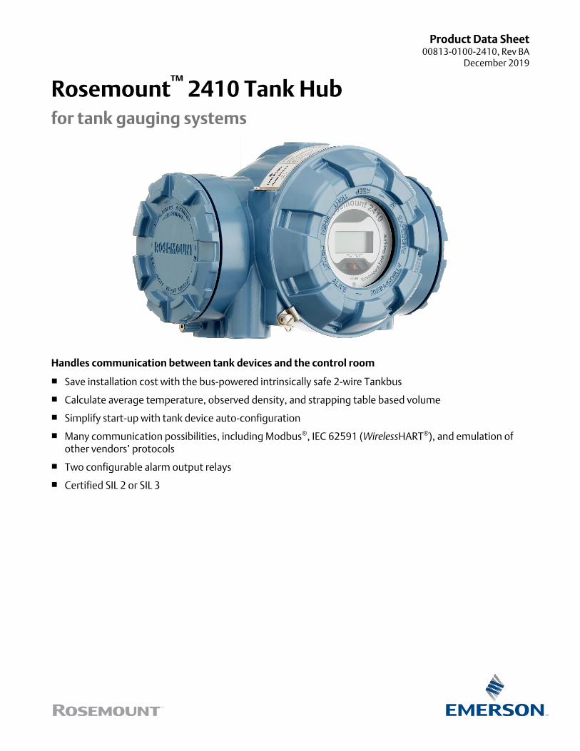
Rosemount™ 2410 Tank Hubfor tank gauging systems
Handles communication between tank devices and the control room
■ Save installation cost with the bus-powered intrinsically safe 2-wire Tankbus
■ Calculate average temperature, observed density, and strapping table based volume
■ Simplify start-up with tank device auto-configuration
■ Many communication possibilities, including Modbus®, IEC 62591 (WirelessHART®), and emulation ofother vendors’ protocols
■ Two configurable alarm output relays
■ Certified SIL 2 or SIL 3
Rosemount 2410 Tank Hub for single or multiple tanks
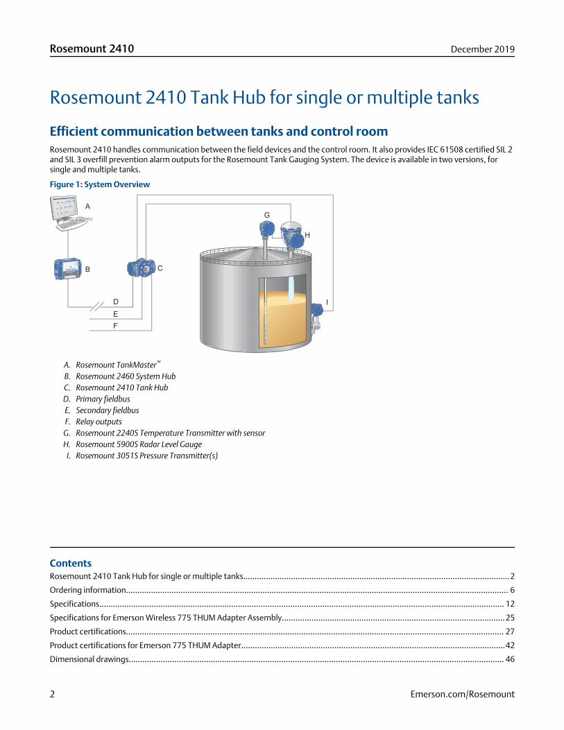
Efficient communication between tanks and control roomRosemount 2410 handles communication between the field devices and the control room. It also provides IEC 61508 certified SIL 2and SIL 3 overfill prevention alarm outputs for the Rosemount Tank Gauging System. The device is available in two versions, forsingle and multiple tanks.
Figure 1: System Overview
A
C
D
E
F
G
H
I
B
A. Rosemount TankMaster™
B. Rosemount 2460 System HubC. Rosemount 2410 Tank HubD. Primary fieldbusE. Secondary fieldbusF. Relay outputs
G. Rosemount 2240S Temperature Transmitter with sensorH. Rosemount 5900S Radar Level Gauge
I. Rosemount 3051S Pressure Transmitter(s)
ContentsRosemount 2410 Tank Hub for single or multiple tanks.....................................................................................................................2
Ordering information........................................................................................................................................................................ 6
Specifications.................................................................................................................................................................................. 12
Specifications for Emerson Wireless 775 THUM Adapter Assembly..................................................................................................25
Product certifications...................................................................................................................................................................... 27
Product certifications for Emerson 775 THUM Adapter....................................................................................................................42
Dimensional drawings..................................................................................................................................................................... 46
Rosemount 2410 December 2019
2 Emerson.com/Rosemount

Tankbus communication
The Rosemount 2410 Tank Hub communicates with and powers the devices on one or several tanks via the Tankbus.
The Tankbus complies with Fieldbus Intrinsically Safe Concept (FISCO) FOUNDATION™ Fieldbus.
By using FISCO, there is no need to take entity parameters into consideration. It makes it easy to connect devices.
In addition, the available power from a FISCO power supply is higher compared to a conventional entity power supply. This enablesthe connection of more devices on the Tankbus.
Auto-configure tank devices
The Rosemount 2410 supports the auto-configuration of the Tankbus devices within the Rosemount Tank Gauging System. It actsas a FOUNDATION Fieldbus master on the Tankbus, which means it identifies and auto-addresses field devices in the network,manages communication, and supervises the status of all connected devices. It also includes extensive built-in diagnostics.
Data handling and calculation
Rosemount 2410 collects measurement values such as level, temperature, and pressure.
It calculates average temperature, observed density, and strapping table based volume.
Such data can be presented on the optional integrated back-lit display, a separate Rosemount 2230 Graphical Field Display, and canbe sent to Rosemount TankMaster or a host system.
Improve data security
All tank hubs have a software write-protection function.
In addition, the Rosemount 2410 with display option is equipped with a hardware write-protection switch.
Control room communication
Rosemount 2410 has slots for two independent communication boards (primary and secondary fieldbus) for TRL2 Modbus, RS485Modbus, emulation, and wireless communication.
Power supply with built-in cable terminatorRosemount 2410 supplies power to the units on the Tankbus.
It is equipped with an integrated FISCO-certified IS barrier, has power conditioner functionality, and built-in electronics for bustermination. A terminator at each end of the Tankbus ensures that the fieldbus network has proper signal levels.
All these features enable the easy setup of the Rosemount Tank Gauging System.
Analog input/outputThe Rosemount 2410 Tank Hub can be ordered with:
■ An analog input
■ An analog output for connection to a host system
■ The analog output is available as certified SIL 2 for overfill prevention or dry-run protection. Suitable for connection to anautomatic overfill prevention system.
December 2019 Rosemount 2410
Emerson.com/Rosemount 3

Emulate gauges from other vendorsRosemount 2410 enables replacement of old mechanical/servo gauges with modern Rosemount devices.
When an old gauge from another vendor is replaced with a tank hub connected to a Rosemount field device, the tank hub will actjust like the replaced gauge.
By using the other vendor’s field and control room communication protocol together with modern Rosemount tank gaugingdevices, the legacy system can be modernized step-by-step. The legacy system can be upgraded while tanks are in operation, andthe existing wiring can be re-used.
Figure 2: Emulation
A
B
C
DE
E
A. Existing host system from other vendorB. Existing data polling unitC. Rosemount 2410 Tank HubD. Rosemount 5900S Radar Level GaugeE. Gauges from other vendor in an existing system
Rosemount 2410 and Rosemount 5900S replacing a servo gauge in a system from another vendor. Rosemount devices areseamlessly integrated into the existing system.
Output relay functionalityRosemount 2410 can be equipped with two solid-state relays that can be configured to be controlled by level, temperature, andwater level. The output is normally connected to an external system for alarm indication or process control.
These relays are user-configurable for normally open or closed operation. They can be either certified SIL 2, and used for overfillprevention via an emergency shutdown system (ESD), or non-SIL.
A third separate relay dedicated for SIL 3 overfill functionality can also be included. This relay is activated both if the alarm level isreached and/or if a device malfunction occurs. It operates in a normally closed mode, and the output can be connected to an ESDsystem.
Rosemount 2410 December 2019
4 Emerson.com/Rosemount
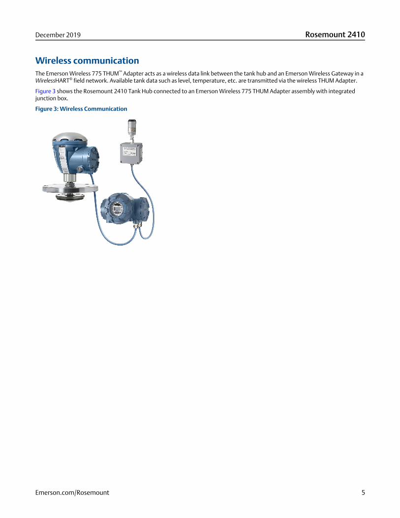
Wireless communicationThe Emerson Wireless 775 THUM™ Adapter acts as a wireless data link between the tank hub and an Emerson Wireless Gateway in aWirelessHART® field network. Available tank data such as level, temperature, etc. are transmitted via the wireless THUM Adapter.
Figure 3 shows the Rosemount 2410 Tank Hub connected to an Emerson Wireless 775 THUM Adapter assembly with integratedjunction box.
Figure 3: Wireless Communication
December 2019 Rosemount 2410
Emerson.com/Rosemount 5

Ordering information
Rosemount 2410 Tank Hub
Additional information:
Specifications
Product certifications
Dimensional drawings
Table 1: Rosemount 2410 Tank Hub Ordering Information
Model Product description
2410 Tank Hub
Tankbus: number of tanks
S(1) Single tank
M(2) Multiple tanks (up to ten level devices per tank hub)
Tankbus: power and communication
F Intrinsically safe FOUNDATION™ Fieldbus (IEC 61158) power supply
Primary fieldbus
R TRL2 Modbus
4 RS485 Modbus
E Enraf® Bi-phase Mark GPU
B(3) Analog output 4-20 mA/HART®, passive (non-IS)
7(3) Analog input 4-20 mA/HART®, passive (non-IS)
Secondary fieldbus
R(4) TRL2 Modbus
E(4) Enraf Bi-phase Mark GPU
W(5)(6) WirelessHART® (IEC 62591) connectivity (IS)
L(4) L&J Tankway Slave 1500 XL/MCG 2000
V(4) Varec® Mark/Space GT 1800/1900
H(4) Whessoe WM 550/660 (digital current loop)
G(4) GPE 31422/31423 (digital current loop)
U(4) Sakura(MDP/V1)
Rosemount 2410 December 2019
6 Emerson.com/Rosemount

Table 1: Rosemount 2410 Tank Hub Ordering Information (continued)
T(4) Tokyo Keiso
C(6)(7) Analog output 4-20 mA/HART, active (IS)
A(6)(7) Analog output 4-20 mA/HART, active (non-IS)
D(7) Analog output 4-20 mA/HART, passive (IS)
B(7) Analog output 4-20 mA/HART, passive (non-IS)
8(6)(7) Analog input 4-20 mA/HART, active (IS)
6(6)(7) Analog input 4-20 mA/HART, active (non-IS)
9(7) Analog input 4-20 mA/HART, passive (IS)
7(7) Analog input 4-20 mA/HART, passive (non-IS)
0(7) None
F(7) None, ready for upgrade of secondary bus
Safety certification (SIS)
3(8)(9) Certified IEC 61508 SIL 3 (Using relay 1xSPST, solid-state. Certification is valid only when connected to a safety-certified Rosemount 5900 according to reference manual).
S(9)(10) Certified IEC 61508 SIL 2 (using analog or relay output)
F(9)(10)(11) None, ready for upgrade of safety certification (SIS)
0 None
Relay output
2 2xSPST, solid-state
1 1xSPST, solid-state
F None, ready for upgrade of relay output
0 None
Integral display
1 LCD
0 None
Power supply
P Extended input range: 48-240 Vac at 50/60 Hz, and 24-48 Vdc
Firmware
S Standard
Hazardous location certification
E1 ATEX Flameproof
E7 IECEx Flameproof
E5 FM-US Explosion-proof
E6 FM-Canada Explosion-proof
E4(12)(13) Japan Flameproof
E2 INMETRO Flameproof (Brazil)
December 2019 Rosemount 2410
Emerson.com/Rosemount 7

Table 1: Rosemount 2410 Tank Hub Ordering Information (continued)
EP(14) KC Flameproof (South Korea)
EW CCOE/PESO Flameproof Certification (India)
EM Technical Regulations Customs Union (EAC) Flameproof
NA No hazardous location certification
Custody transfer type approval(15)
R OIML R85 E 2008 performance certification
A CMI (Czech Republic W&M approval)
B NMI (Australia)
C PTB (German W&M approval)
E TJA (Estonia W&M approval)
G GUM (Poland)
I Ministero (Italy)
K(16) GOST (Kazakhstan)
L LNE (France)
M BMS (Belgium W&M)
N NMi (the Netherlands W&M approval)
O ONML (Algeria)
Q IPQ (Portugal)
S(16) GOST (Russia)
T ANM (Tunisia)
W METAS (Switzerland W&M approval)
Y Justervesenet (Norway W&M approval)
0 None
Housing
A Aluminum (polyurethane-covered), IP 66/67
Cable/conduit connections
1 ½-14 NPT and ¾-14 NPT Female thread, includes:■ 1 pcs 1½-14 NPT plug
■ 2 pcs ¾-14 NPT plugs
2 M20 x 1.5 and M25 x 1.5 adapters Female thread, includes:■ 1 pcs 1½-14 NPT plug
■ 2 pcs ¾-14 NPT plugs
■ 4 pcs 1½-14 NPT->M20x1.5 adapters
■ 2 pcs ¾-14 NPT->M25x1.5 adapters
Rosemount 2410 December 2019
8 Emerson.com/Rosemount

Table 1: Rosemount 2410 Tank Hub Ordering Information (continued)
G(17) Metal cable glands (½-14 and ¾-14 NPT) Includes:■ 1 pcs 1½-14 NPT plug
■ 2 pcs ¾-14 NPT plugs
■ 4 pcs ¾-14 NPT cable glands
■ 2 pcs 1½-14 NPT cable glands
E eurofast® male connector Includes:■ 1 pcs male connector
■ 1 pcs 1½-14 NPT plug
■ 2 pcs ¾-14 NPT plugs
M minifast® male connector
Mechanical installation
W Mounting kit for wall installation
P Mounting kit for both wall and pipe installation (1-2-in. vertical or horizontal pipes)
Options (include with selected model number)
Safety certificate
QT(18) IEC 61508 certificate and FMEDA data
Overfill protection approval
U1(19) TÜV/DIBt WHG approval for overfill protection
U2(19) SVTI approval for overfill protection (Switzerland)
Tag plate
ST Engraved SST tag plate
Extended warranty
WR3 3-year limited warranty
WR5 5-year limited warranty
Typical Model Number: 2410 S F R 0 3 2 1 P S E1 R A 1 P ST
(1) Supports one Rosemount 5900S 2-in-1 gauge or up to two Rosemount 5900 standard gauges.(2) Up to five Rosemount 5300, up to 10 Rosemount 5408 per tank hub.(3) Requires Secondary Fieldbus code W.(4) Requires Primary Fieldbus code R or 4.(5) Requires a separate Emerson Wireless 775 THUM Adapter (not included, to be ordered as a separate item).(6) Power-supply integrated. Maximum Tankbus current reduced to 200 mA.(7) Requires Primary Fieldbus code R, 4 or E.(8) Requires Secondary Fieldbus code 0, or Secondary Fieldbus code W, C, D, 8, 9, and Primary Fieldbus code 4.(9) Requires Number of tanks code S.(10) Requires Relay output code 2 or 1, or Primary Fieldbus Code B, or Secondary Fieldbus code A, B, C or D for SIL 2 (Safety certification code S).(11) Requires Secondary Fieldbus code 0 or F for SIL3 (Safety certification code 3).(12) Requires Secondary Fieldbus code T or U.(13) Requires Cable/conduit connections code 1.(14) Requires Custody transfer type approval code R or 0.(15) Requires a Rosemount 5900S Radar Level Gauge with corresponding Custody transfer type approval.(16) Requires Hazardous location certification code E1.(17) Min. temperature -20 °C (-4 °F). ATEX/IECEx Ex e approved.(18) Requires Safety certification (SIS) code S or 3.(19) Requires Safety certification (SIS) code 3, or Relay output code 1 or 2.
December 2019 Rosemount 2410
Emerson.com/Rosemount 9

Emerson Wireless 775 THUM Adapter Assembly
■ Add wireless access to any measurement point
■ Wireless output protected by industry leading security
■ Gain access to additional information such as diagnostics or multivariable data
Additional information
Specifications for Emerson Wireless 775 THUM Adapter Assembly
Product certifications for Emerson 775 THUM Adapter
Dimensional drawings
Table 2: Emerson Wireless THUM Adapter Assembly Ordering Information
Model Product description
775TG(1) Wireless 775 THUM Adapter Assembly Tank Gauging
Output
X Wireless
Housing
D Aluminum
Mounting connection
2 M20 Conduit adapter
Input protocol
1 Hart Data
Certification
NA No approval
I1 ATEX Intrinsically Safe
I2 INMETRO Intrinsically Safe
I3 NEPSI
H4(2) TIIS
I5 FM Intrinsically Safe, Non-incendive
I6 CSA Intrinsically Safe
I7 IECEX Intrinsically Safe
Rosemount 2410 December 2019
10 Emerson.com/Rosemount
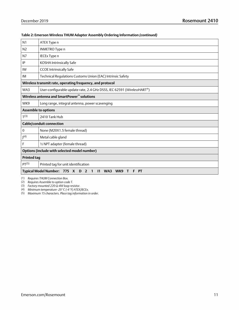
Table 2: Emerson Wireless THUM Adapter Assembly Ordering Information (continued)
N1 ATEX Type n
N2 INMETRO Type n
N7 IECEx Type n
IP KOSHA Intrinsically Safe
IW CCOE Intrinsically Safe
IM Technical Regulations Customs Union (EAC) Intrinsic Safety
Wireless transmit rate, operating frequency, and protocol
WA3 User-configurable update rate, 2.4 GHz DSSS, IEC 62591 (WirelessHART®)
Wireless antenna and SmartPower™ solutions
WK9 Long range, integral antenna, power scavenging
Assemble to options
T(3) 2410 Tank Hub
Cable/conduit connection
0 None (M20X1.5 female thread)
J(4) Metal cable gland
F ½ NPT adapter (female thread)
Options (include with selected model number)
Printed tag
PT(5) Printed tag for unit identification
Typical Model Number: 775 X D 2 1 I1 WA3 WK9 T F PT
(1) Requires THUM Connection Box.(2) Requires Assemble to option code T.(3) Factory mounted 220 Ω 4W loop resistor.(4) Minimum temperature -20 °C (-4 °F) ATEX/IECEx.(5) Maximum 15 characters. Place tag information in order.
December 2019 Rosemount 2410
Emerson.com/Rosemount 11

Specifications
General specifications
Single tank version■ Supports one Rosemount 5900S 2-in-1 gauge or up to two Rosemount 5900 standard gauges
■ Total Observed Volume (TOV) and API corrected Net Standard Volume (NSV) calculation with 100-point strapping table
Multiple tank versionFor a Rosemount 5300/5408/5900 system configuration:
■ The software supports 16 field devices and 10 tanks per tank hub
■ Maximum five type Rosemount 5300 gauges per tank hub
The actual number of tanks/instruments a tank hub supports depends on the configuration, which types of units are connected andhow many:
■ Hybrid calculations (mass and density) for up to three tanks
■ Total Observed Volume (TOV) and API corrected Net Standard Volume (NSV) calculation with 100-point strapping table for onetank
For more information, see Table 6.
Examples of connected field devicesRadar level gauges (type 5900(1), 5300, and 5408), Rosemount 2240S Multi-input Temperature Transmitter, Rosemount 644Temperature Transmitter, Temperature/Water Level Sensors, Rosemount 3051S Scalable Pressure Transmitter, Rosemount 2230Graphical Field Display
Start-up timeLess than 30 s
(1) One Rosemount 5900S with a 2-in-1 solution or maximum two standard Rosemount 5900 gauges installed on separate tanks can be connected to one tank hub.
Rosemount 2410 December 2019
12 Emerson.com/Rosemount
Communication/display/configuration specifications
TankbusThe intrinsically safe side of the Rosemount 2410 connects to the Tankbus, which communicates with the field devices on the tankusing FOUNDATION™ Fieldbus.
FieldbusRosemount 2410 communicates with a Rosemount 2460 System Hub, Rosemount TankMaster, or a host via the supportedcommunication protocols for the primary and secondary fieldbus.
Primary fieldbus: TRL2 Modbus, RS485 Modbus, Analog output/input 4-20 mA/HART or Enraf®
Secondary fieldbus: TRL2 Modbus, Analog output/input 4-20 mA/HART, WirelessHART® or other vendors’ protocols, such asEnraf, L&J Tankway and Sakura MDP/V1
For combination guidance, see Table 3 and Table 4.
Relay outputs
SIL 3 relay output: One certified SIL 3 relay is available for overfill prevention. This non-intrinsically safe solid state relay isclosed/energized during normal operation.
Maximum voltage and current: 260 Vac/Vdc, 80 mA single pole
Relay outputs (SIL 2or non-SIL):
Maximum two relays, controlled by 10 independent virtual relay functions, which can be configured fordifferent tanks and process variables. The two non-intrinsically safe solid state relays are user configurablefor normally energized or de-energized operation.
Maximum voltage and current: 350 Vac/Vdc, 80 mA single pole
For combination guidance, see Table 3 and Table 4.
Analog input/outputThe tank hub supports analog output and input 4-20 mA/HART, active or passive, IS or non-IS. The analog output is available ascertified SIL 2.
Analog input
Maximum number of input channels: 1
Input Current range: 0-23 mA
Configurable Min and Max alarm limits.
For IS parameters, see Product certifications.
External Supply Voltage:
■ Passive Non-IS: 7.2 - 35 Vdc
■ Passive IS: 8.7 – 30 Vdc
Maximum Output Voltage (open loop):
■ Active Non-IS: 24 Vdc
■ Active IS: 23 Vdc
HART master:
■ Maximum 5 HART Slave Devices (Passive)
■ Maximum 3 HART Slave Devices (Active)
December 2019 Rosemount 2410
Emerson.com/Rosemount 13
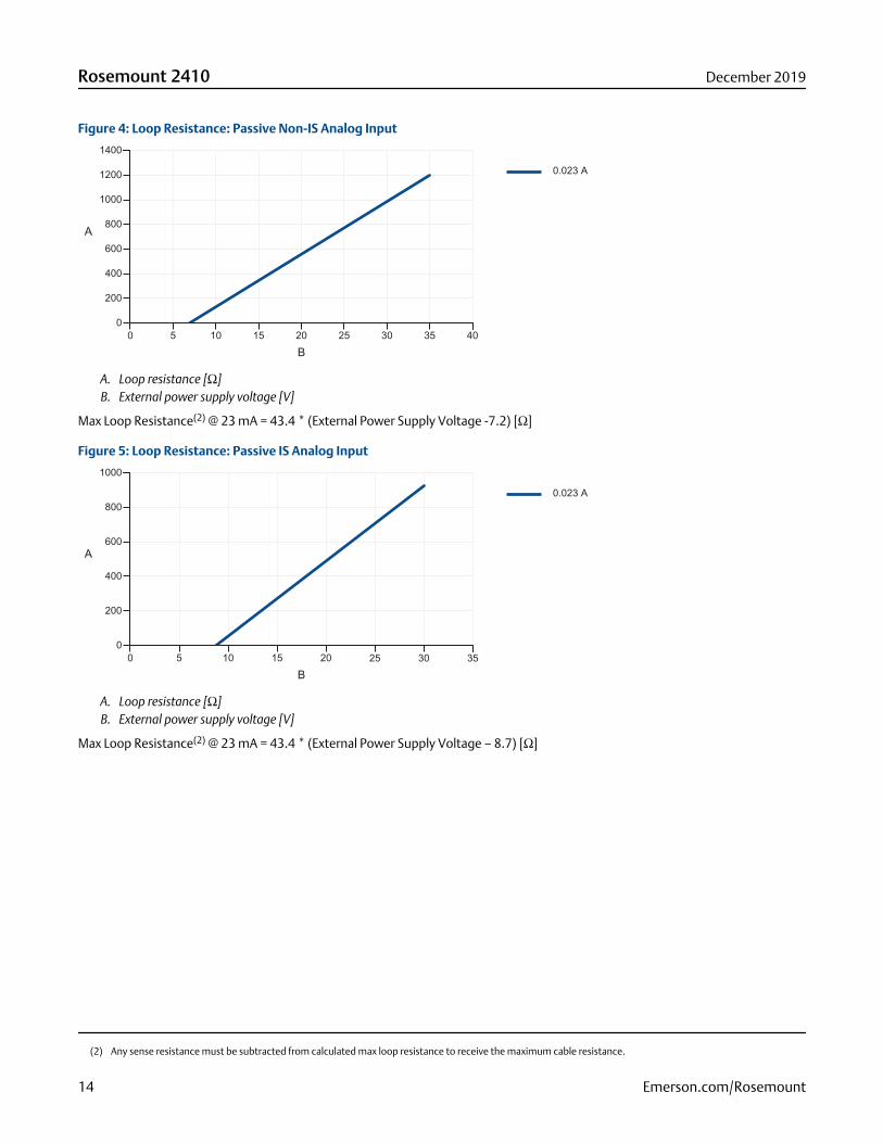
Figure 4: Loop Resistance: Passive Non-IS Analog Input
A. Loop resistance [Ω]B. External power supply voltage [V]
Max Loop Resistance(2) @ 23 mA = 43.4 * (External Power Supply Voltage -7.2) [Ω]
Figure 5: Loop Resistance: Passive IS Analog Input
A. Loop resistance [Ω]B. External power supply voltage [V]
Max Loop Resistance(2) @ 23 mA = 43.4 * (External Power Supply Voltage – 8.7) [Ω]
(2) Any sense resistance must be subtracted from calculated max loop resistance to receive the maximum cable resistance.
Rosemount 2410 December 2019
14 Emerson.com/Rosemount
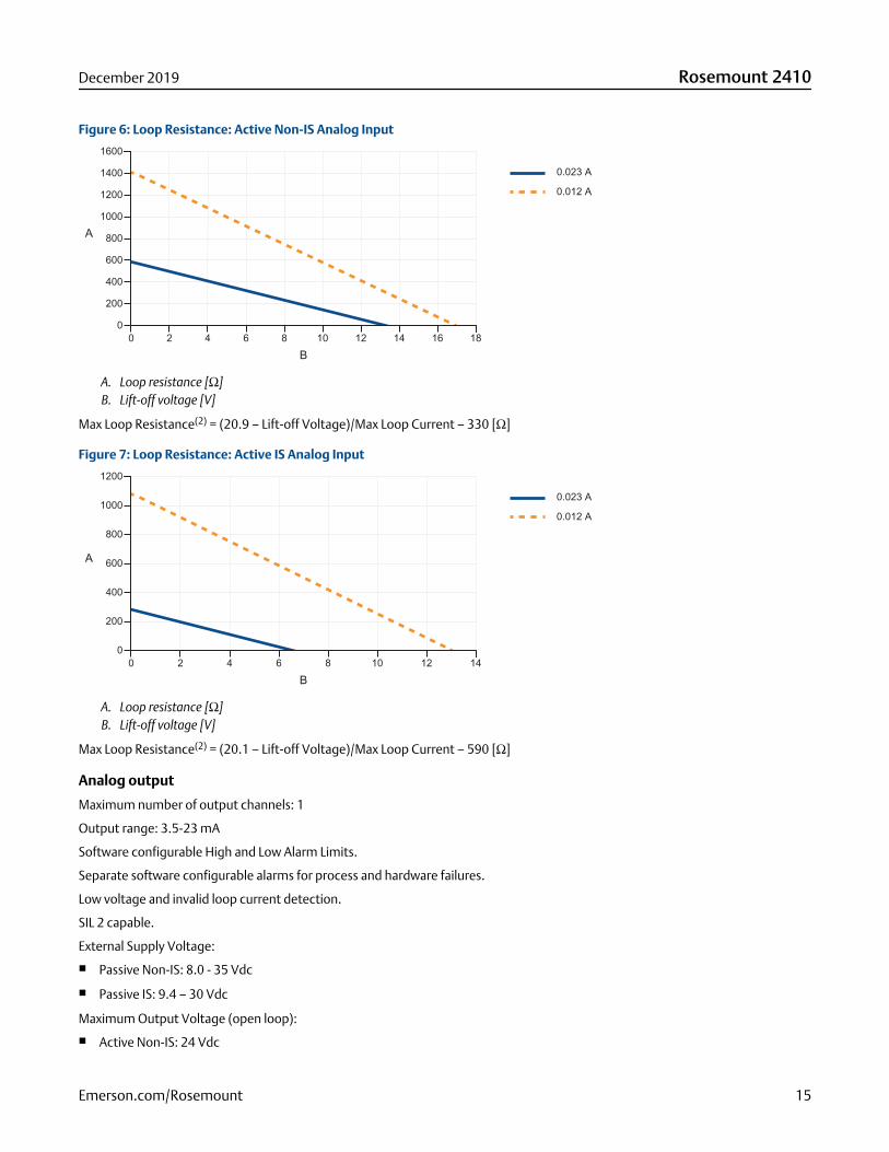
Figure 6: Loop Resistance: Active Non-IS Analog Input
A. Loop resistance [Ω]B. Lift-off voltage [V]
Max Loop Resistance(2) = (20.9 – Lift-off Voltage)/Max Loop Current – 330 [Ω]
Figure 7: Loop Resistance: Active IS Analog Input
A. Loop resistance [Ω]B. Lift-off voltage [V]
Max Loop Resistance(2) = (20.1 – Lift-off Voltage)/Max Loop Current – 590 [Ω]
Analog output
Maximum number of output channels: 1
Output range: 3.5-23 mA
Software configurable High and Low Alarm Limits.
Separate software configurable alarms for process and hardware failures.
Low voltage and invalid loop current detection.
SIL 2 capable.
External Supply Voltage:
■ Passive Non-IS: 8.0 - 35 Vdc
■ Passive IS: 9.4 – 30 Vdc
Maximum Output Voltage (open loop):
■ Active Non-IS: 24 Vdc
December 2019 Rosemount 2410
Emerson.com/Rosemount 15
■ Active IS: 23 Vdc
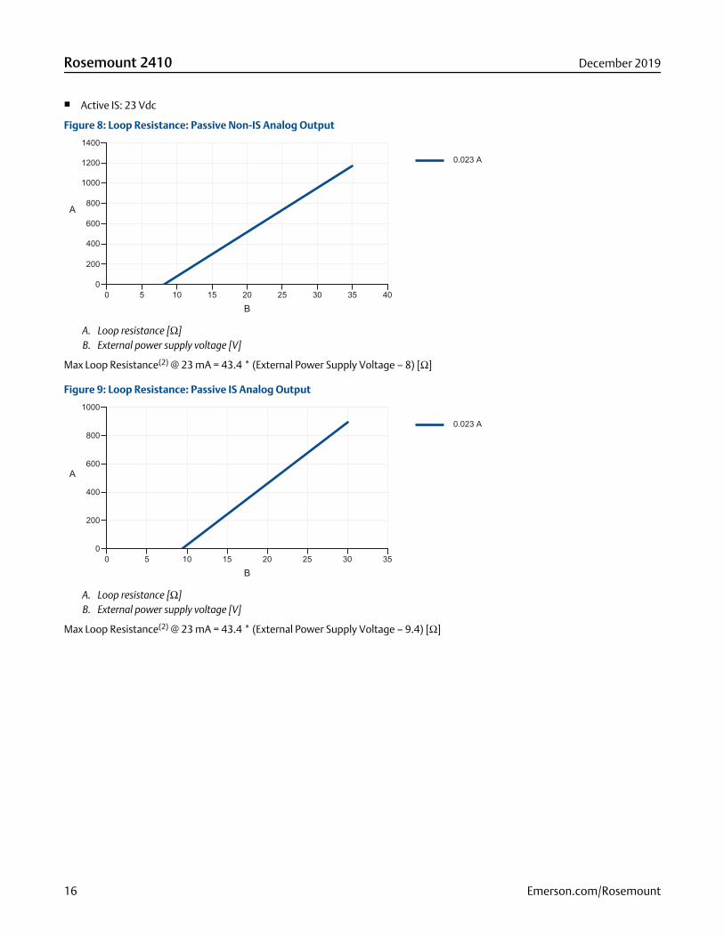
Figure 8: Loop Resistance: Passive Non-IS Analog Output
A. Loop resistance [Ω]B. External power supply voltage [V]
Max Loop Resistance(2) @ 23 mA = 43.4 * (External Power Supply Voltage – 8) [Ω]
Figure 9: Loop Resistance: Passive IS Analog Output
A. Loop resistance [Ω]B. External power supply voltage [V]
Max Loop Resistance(2) @ 23 mA = 43.4 * (External Power Supply Voltage – 9.4) [Ω]
Rosemount 2410 December 2019
16 Emerson.com/Rosemount

Figure 10: Loop Resistance: Active Non-IS Analog Output
A. Loop resistance [Ω]B. Lift-off voltage [V]
Max Loop Resistance(2) = (20.3 – Lift-off Voltage)/Max Loop Current – 330 [Ω]
Figure 11: Loop Resistance: Active IS Analog Output
A. Loop resistance [Ω]B. Lift-off voltage [V]
Max Loop Resistance(2) = (19.5 – Lift-off Voltage)/Max Loop Current – 600 [Ω]
Fieldbus combinationsTable 3: Fieldbus Combination Matrix (Non-SIL)
Primary Fieldbus options
TRL2 RS485 Enraf Analog outpassive (non-IS)
Analog Inpassive (non-IS)
Secondary Fieldbus options Code R 4 E B 7
TRL2 R Yes Yes No No No
Enraf E Yes Yes No No No
WirelessHART® W Yes Yes Yes Yes Yes
L&J Tankway 1500 XL/MCG2000
L Yes Yes No No No
December 2019 Rosemount 2410
Emerson.com/Rosemount 17

Table 3: Fieldbus Combination Matrix (Non-SIL) (continued)
Primary Fieldbus options
TRL2 RS485 Enraf Analog outpassive (non-IS)
Analog Inpassive (non-IS)
Secondary Fieldbus options Code R 4 E B 7
Varec Mark/Space GT1800/1900
V Yes Yes No No No
Whessoe WM 550/660(digital current loop)
H Yes Yes No No No
GPE 31422/31423 (digitalcurrent loop)
G Yes Yes No No No
Sakura MDP/V1 U Yes Yes No No No
Tokyo Keiso T Yes Yes No No No
Analog out active (IS) C Yes Yes Yes No No
Analog out active (non-IS) A Yes Yes Yes No No
Analog out passive (IS) D Yes Yes Yes No No
Analog out passive (non-IS) B Yes Yes Yes No No
Analog in active (IS) 8 Yes Yes Yes No No
Analog in active (non-IS) 6 Yes Yes Yes No No
Analog in passive (IS) 9 Yes Yes Yes No No
Analog in passive (non-IS) 7 Yes Yes Yes No No
None 0 Yes Yes Yes No No
Ready for upgrade F Yes Yes Yes No No
Yes = Primary Fieldbus and Secondary Fieldbus can be combined
No = Combination not possible
Table 4: Fieldbus Combination Matrix (SIL)
Primary Fieldbus options
TRL2 RS485 Enraf Analog outpassive (non-IS)
Analog Inpassive(non-IS)
Secondary Fieldbusoptions
Code R 4 E B 7
TRL2 R SIL 2 (relay) SIL 2 (relay) No No No
Enraf E SIL 2 (relay) SIL 2 (relay) No No No
WirelessHART W SIL 2 (relay) SIL 2 (relay) or SIL3 (relay)
SIL 2 (relay) SIL 2 (4-20 mAand/or relay)
SIL 2 (relay)
L&J Tankway 1500 XL/MCG2000
L SIL 2 (relay) SIL 2 (relay) No No No
Varec Mark/Space GT1800/1900
V SIL 2 (relay) SIL 2 (relay) No No No
Rosemount 2410 December 2019
18 Emerson.com/Rosemount
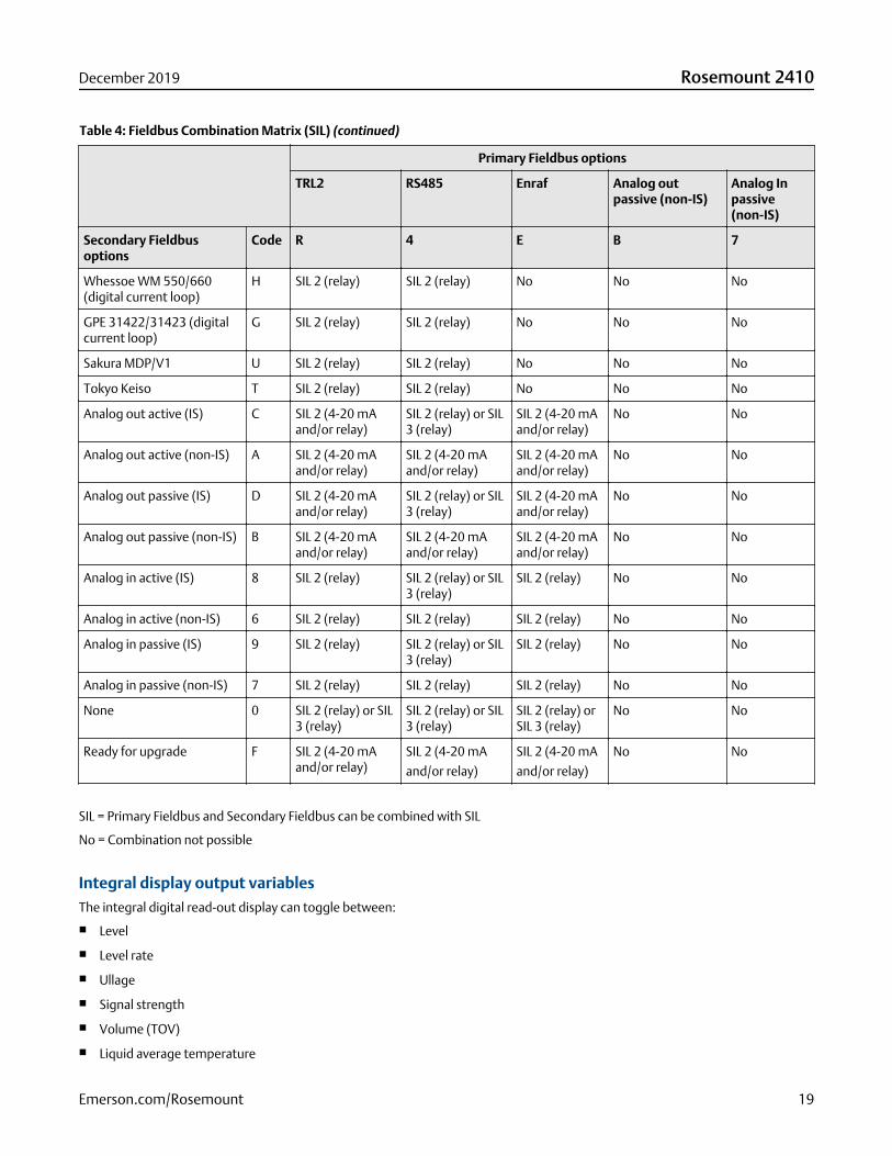
Table 4: Fieldbus Combination Matrix (SIL) (continued)
Primary Fieldbus options
TRL2 RS485 Enraf Analog outpassive (non-IS)
Analog Inpassive(non-IS)
Secondary Fieldbusoptions
Code R 4 E B 7
Whessoe WM 550/660(digital current loop)
H SIL 2 (relay) SIL 2 (relay) No No No
GPE 31422/31423 (digitalcurrent loop)
G SIL 2 (relay) SIL 2 (relay) No No No
Sakura MDP/V1 U SIL 2 (relay) SIL 2 (relay) No No No
Tokyo Keiso T SIL 2 (relay) SIL 2 (relay) No No No
Analog out active (IS) C SIL 2 (4-20 mAand/or relay)
SIL 2 (relay) or SIL3 (relay)
SIL 2 (4-20 mAand/or relay)
No No
Analog out active (non-IS) A SIL 2 (4-20 mAand/or relay)
SIL 2 (4-20 mAand/or relay)
SIL 2 (4-20 mAand/or relay)
No No
Analog out passive (IS) D SIL 2 (4-20 mAand/or relay)
SIL 2 (relay) or SIL3 (relay)
SIL 2 (4-20 mAand/or relay)
No No
Analog out passive (non-IS) B SIL 2 (4-20 mAand/or relay)
SIL 2 (4-20 mAand/or relay)
SIL 2 (4-20 mAand/or relay)
No No
Analog in active (IS) 8 SIL 2 (relay) SIL 2 (relay) or SIL3 (relay)
SIL 2 (relay) No No
Analog in active (non-IS) 6 SIL 2 (relay) SIL 2 (relay) SIL 2 (relay) No No
Analog in passive (IS) 9 SIL 2 (relay) SIL 2 (relay) or SIL3 (relay)
SIL 2 (relay) No No
Analog in passive (non-IS) 7 SIL 2 (relay) SIL 2 (relay) SIL 2 (relay) No No
None 0 SIL 2 (relay) or SIL3 (relay)
SIL 2 (relay) or SIL3 (relay)
SIL 2 (relay) orSIL 3 (relay)
No No
Ready for upgrade F SIL 2 (4-20 mAand/or relay)
SIL 2 (4-20 mA
and/or relay)
SIL 2 (4-20 mA
and/or relay)
No No
SIL = Primary Fieldbus and Secondary Fieldbus can be combined with SIL
No = Combination not possible
Integral display output variablesThe integral digital read-out display can toggle between:
■ Level
■ Level rate
■ Ullage
■ Signal strength
■ Volume (TOV)
■ Liquid average temperature
December 2019 Rosemount 2410
Emerson.com/Rosemount 19
■ 1-16 spot temperature
■ Vapor average temperature
■ Ambient temperature
■ Free water level
■ Vapor pressure
■ Liquid pressure
■ Air pressure
■ Observed density
■ Reference density
■ Flow rate
Display output units
Level, free water level, and ullage: meter, millimeter, feet, or imperial 1/16
Level rate: meter/second, meter/hour, feet/second, or feet/hour
Flow rate: meter³/hour, liter/minute, barrel/hour, or US gallon/hour
Total Observed Volume (TOV): meter³, liters, barrel, or US gallon
Temperature: °F, °C, or °K
Pressure: psi, psiA, psiG, bar, barA or barG, atm, Pa, or kPa
Density: kg/m³, °API, or 60/60DegF
Signal strength: mV
Density, mass, and more volume parameters are calculated in Rosemount TankMaster (GOV, GSV, NSV, WIA/WIV).
Configuration toolsRosemount TankMaster
Autoconfiguration supportYes (Tankbus addressing)
Rosemount 2410 December 2019
20 Emerson.com/Rosemount
Electrical specifications
Power supply (nominal values)24-48 Vdc (-15% to +10%) 48-240 Vac (-15% to +10%), 50/60 Hz
Power consumptionMax. 20 W depending on configuration.
Recommended Miniature Circuit Breaker (MCB): 2A slow
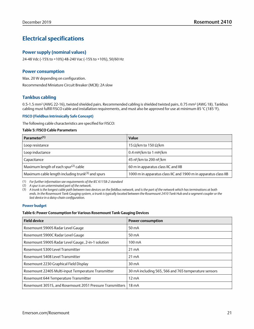
Tankbus cabling0.5-1.5 mm² (AWG 22-16), twisted shielded pairs. Recommended cabling is shielded twisted pairs, 0.75 mm² (AWG 18). Tankbuscabling must fulfill FISCO cable and installation requirements, and must also be approved for use at minimum 85 °C (185 °F).
FISCO (Fieldbus Intrinsically Safe Concept)
The following cable characteristics are specified for FISCO:
Table 5: FISCO Cable Parameters
Parameter(1) Value
Loop resistance 15 Ω/km to 150 Ω/km
Loop inductance 0.4 mH/km to 1 mH/km
Capacitance 45 nF/km to 200 nF/km
Maximum length of each spur(2) cable 60 m in apparatus class IIC and IIB
Maximum cable length including trunk(3) and spurs 1000 m in apparatus class IIC and 1900 m in apparatus class IIB
(1) For further information see requirements of the IEC 61158-2 standard(2) A spur is an unterminated part of the network.(3) A trunk is the longest cable path between two devices on the fieldbus network, and is the part of the network which has terminations at both
ends. In the Rosemount Tank Gauging system, a trunk is typically located between the Rosemount 2410 Tank Hub and a segment coupler or thelast device in a daisy-chain configuration.
Power budget
Table 6: Power Consumption for Various Rosemount Tank Gauging Devices
Field device Power consumption
Rosemount 5900S Radar Level Gauge 50 mA
Rosemount 5900C Radar Level Gauge 50 mA
Rosemount 5900S Radar Level Gauge, 2-in-1 solution 100 mA
Rosemount 5300 Level Transmitter 21 mA
Rosemount 5408 Level Transmitter 21 mA
Rosemount 2230 Graphical Field Display 30 mA
Rosemount 2240S Multi-input Temperature Transmitter 30 mA including 565, 566 and 765 temperature sensors
Rosemount 644 Temperature Transmitter 12 mA
Rosemount 3051S, and Rosemount 2051 Pressure Transmitters 18 mA
December 2019 Rosemount 2410
Emerson.com/Rosemount 21
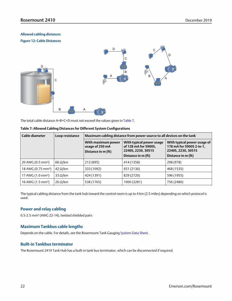
Allowed cabling distances
Figure 12: Cable Distances
D
C
B A
D
D
C
C
B
B
AA
The total cable distance A+B+C+D must not exceed the values given in Table 7.
Table 7: Allowed Cabling Distances for Different System Configurations
Cable diameter Loop resistance Maximum cabling distance from power source to all devices on the tank
With maximum powerusage of 250 mA
Distance in m (ft)
With typical power usageof 128 mA for 5900S,2240S, 2230, 3051S
Distance in m (ft)
With typical power usage of178 mA for 5900S 2-in-1,2240S, 2230, 3051S
Distance in m (ft)
20 AWG (0.5 mm²) 66 Ω/km 212 (695) 414 (1358) 298 (978)
18 AWG (0.75 mm²) 42 Ω/km 333 (1092) 651 (2136) 468 (1535)
17 AWG (1.0 mm²) 33 Ω/km 424 (1391) 829 (2720) 596 (1955)
16 AWG (1.5 mm²) 26 Ω/km 538 (1765) 1000 (3281) 756 (2480)
The typical cabling distance from the tank hub toward the control room is up to 4 km (2.5 miles) depending on which protocol isused.
Power and relay cabling0.5-2.5 mm² (AWG 22-14), twisted shielded pairs
Maximum Tankbus cable lengthsDepends on the cable. For details, see the Rosemount Tank Gauging System Data Sheet.
Built-in Tankbus terminatorThe Rosemount 2410 Tank Hub has a built-in tank bus terminator, which can be disconnected if required.
Rosemount 2410 December 2019
22 Emerson.com/Rosemount
Mechanical specifications
Housing materialPolyurethane-covered die-cast aluminum
Cable entry (connection/glands)Non-IS side: Two ½ - 14 NPT and Two ¾ - 14 NPT entries for cable glands or conduits
IS side: Two ½ - 14 NPT entries for cable glands or conduits
Three metal plugs to seal any unused ports are included in the delivery
Optional:
■ M20 x 1.5 and M25 x 1.5 conduit/cable adapter
■ Cable glands in metal (½ - 14 NPT and ¾ - 14 NPT)
■ 4-pin male eurofast connector or A size Mini 4-pin male minifast connector
InstallationCan be installed on a 33.4-60.3 mm (1-2 in.) diameter pipe or wall, at ground level close to the tank or on top of the tank usingexisting cabling.
Weight4.7 kg (10.4 lbs)
December 2019 Rosemount 2410
Emerson.com/Rosemount 23

Environmental specifications
Temperature limits
Ambient temperature
-40 to 70 °C (-40 to 158 °F). Minimum start-up temperature is -50 °C (-58 °F).
With LCD display: -25 to 70 °C (-13 to 158 °F)
Storage temperature
-50 to 85 °C (-58 to 185 °F)
With LCD display: -40 to 85 °C (-40 to 185 °F)
Humidity0 - 100% relative humidity
Ingress protectionIP 66 and IP 67 (NEMA® 4X)
Metrology sealing possibilityYes
Write-protect switchYes (hardware and software write-protection)
Transient/built-in lightning protectionIn accordance with IEC 61000-4-5, level 4 kV line to ground. Compliant with IEEE 587 category B transient protection and IEEE 472surge protection.
Rosemount 2410 December 2019
24 Emerson.com/Rosemount
Specifications for Emerson Wireless 775 THUM AdapterAssembly
NoteFor more information, see the Emerson Wireless 775 THUM Adapter Product Data Sheet.
General specificationsThe THUM Adapter allows WirelessHART® communication according to the IEC 62591 standard between the Rosemount 2410 TankHub and the Emerson Wireless Gateway. The THUM is integrated with a connection box.
Transmission rangeApplication dependent. Consult factory
Communication specifications
Communication protocolIEC 62591 (WirelessHART®)
Radio characteristics■ Standard IEEE 802.15.4 radio
■ 2.4 GHz ISM band sliced into 16 radio-channels
■ Continually “hop” across channels to avoid interference and increase reliability
■ Direct sequence spread spectrum (DSSS) delivers high reliability in challenging radio environment
Update rateUser selectable, eight seconds to 60 minutes
Electrical specifications
Power supplyPowered by Rosemount 2410 Tank Hub
Output cablingShielded twisted pair wiring, 0.5-2.5 mm² (AWG 22-14)
Maximum cable length depends on cable characteristics.
December 2019 Rosemount 2410
Emerson.com/Rosemount 25

Mechanical specifications
Materials of construction
Housing/enclosure
Polyurethane painted, low-copper aluminum housing
Antenna
Polybutadine terephthalate (PBT)/polycarbonate (PC) integrated omnidirectional antenna
Cable entry (connection/glands)One M20x1.5 entry for cable gland or conduit adapter
Optional:
■ Metal cable gland M20x1.5
■ ½ NPT adapter (female thread)
InstallationThe THUM Adapter can be installed on a vertical or horizontal 1- to 2-in. pipe, away from the tank hub at the best possible tank roofposition. It should be installed approximately 2 m (6 ft) or more from any large structure or conductive surface.
WeightConnection box and THUM Adapter: 2.0 kg (4.4 lbs.)
Environmental specifications
Temperature limits
Ambient temperature
-40 to 85 °C (-40 to 185 °F)
Storage temperature
-40 to 85 °C (-40 to 185 °F)
Humidity limits0 - 100% relative humidity
Ingress protectionIP 66 and NEMA 4X
Rosemount 2410 December 2019
26 Emerson.com/Rosemount
Product certificationsRev 2.11
For more information on product certificates, refer to the Rosemount 2410 Reference Manual.
European directive informationThe most recent revision of the EU Declaration of Conformity can be found at Emerson.com/Rosemount.
Ordinary location certificationAs standard, the transmitter has been examined and tested to determine that the design meets the basic electrical, mechanical,and fire protection requirements by a nationally recognized test laboratory (NRTL) as accredited by the Federal Occupational Safetyand Health Administration (OSHA).
Installing equipment in North AmericaThe US National Electrical Code® (NEC) and the Canadian Electrical Code (CEC) permit the use of Division marked equipment inZones and Zone marked equipment in Divisions. The markings must be suitable for the area classification, gas, and temperatureclass. This information is clearly defined in the respective codes.
December 2019 Rosemount 2410
Emerson.com/Rosemount 27
North America
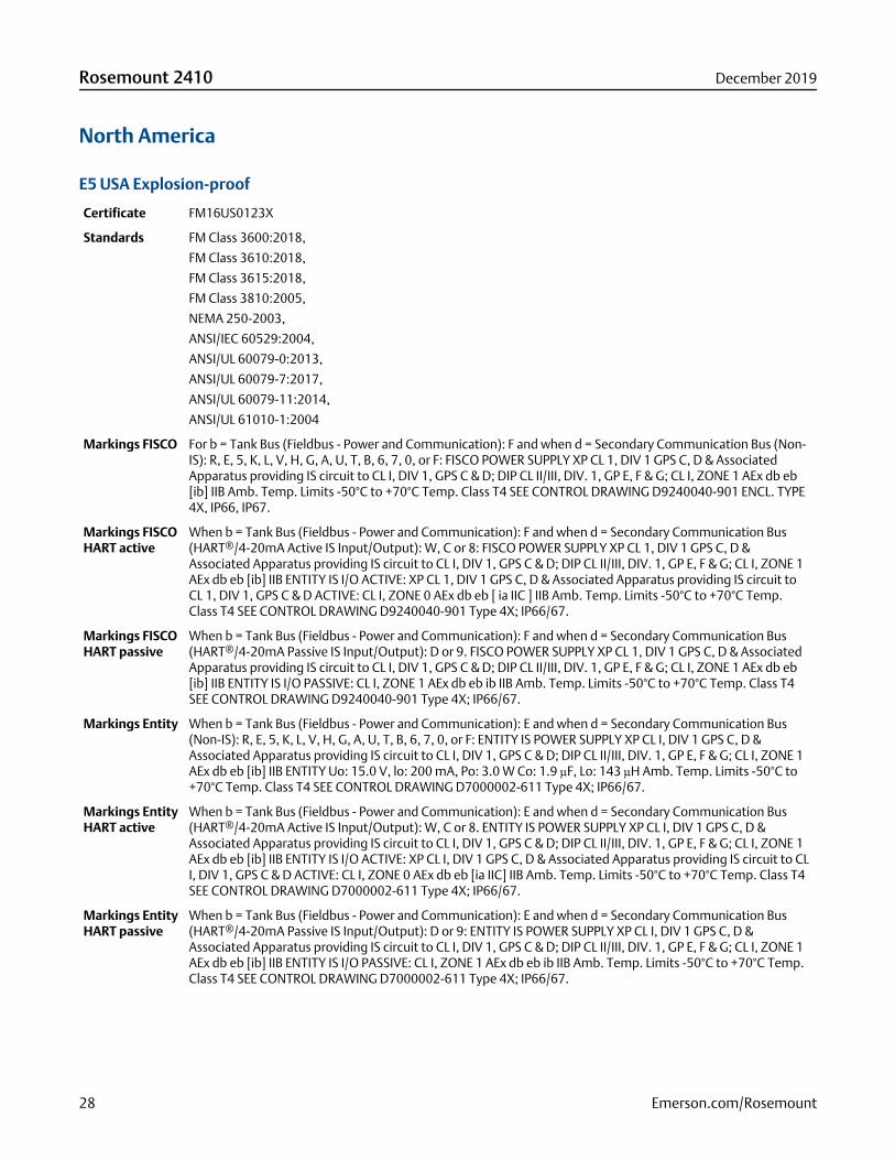
E5 USA Explosion-proof
Certificate FM16US0123X
Standards FM Class 3600:2018,
FM Class 3610:2018,
FM Class 3615:2018,
FM Class 3810:2005,
NEMA 250-2003,
ANSI/IEC 60529:2004,
ANSI/UL 60079-0:2013,
ANSI/UL 60079-7:2017,
ANSI/UL 60079-11:2014,
ANSI/UL 61010-1:2004
Markings FISCO For b = Tank Bus (Fieldbus - Power and Communication): F and when d = Secondary Communication Bus (Non-IS): R, E, 5, K, L, V, H, G, A, U, T, B, 6, 7, 0, or F: FISCO POWER SUPPLY XP CL 1, DIV 1 GPS C, D & AssociatedApparatus providing IS circuit to CL I, DIV 1, GPS C & D; DIP CL II/III, DIV. 1, GP E, F & G; CL I, ZONE 1 AEx db eb[ib] IIB Amb. Temp. Limits -50°C to +70°C Temp. Class T4 SEE CONTROL DRAWING D9240040-901 ENCL. TYPE4X, IP66, IP67.
Markings FISCOHART active
When b = Tank Bus (Fieldbus - Power and Communication): F and when d = Secondary Communication Bus(HART®/4-20mA Active IS Input/Output): W, C or 8: FISCO POWER SUPPLY XP CL 1, DIV 1 GPS C, D &Associated Apparatus providing IS circuit to CL I, DIV 1, GPS C & D; DIP CL II/III, DIV. 1, GP E, F & G; CL I, ZONE 1AEx db eb [ib] IIB ENTITY IS I/O ACTIVE: XP CL 1, DIV 1 GPS C, D & Associated Apparatus providing IS circuit toCL 1, DIV 1, GPS C & D ACTIVE: CL I, ZONE 0 AEx db eb [ ia IIC ] IIB Amb. Temp. Limits -50°C to +70°C Temp.Class T4 SEE CONTROL DRAWING D9240040-901 Type 4X; IP66/67.
Markings FISCOHART passive
When b = Tank Bus (Fieldbus - Power and Communication): F and when d = Secondary Communication Bus(HART®/4-20mA Passive IS Input/Output): D or 9. FISCO POWER SUPPLY XP CL 1, DIV 1 GPS C, D & AssociatedApparatus providing IS circuit to CL I, DIV 1, GPS C & D; DIP CL II/III, DIV. 1, GP E, F & G; CL I, ZONE 1 AEx db eb[ib] IIB ENTITY IS I/O PASSIVE: CL I, ZONE 1 AEx db eb ib IIB Amb. Temp. Limits -50°C to +70°C Temp. Class T4SEE CONTROL DRAWING D9240040-901 Type 4X; IP66/67.
Markings Entity When b = Tank Bus (Fieldbus - Power and Communication): E and when d = Secondary Communication Bus(Non-IS): R, E, 5, K, L, V, H, G, A, U, T, B, 6, 7, 0, or F: ENTITY IS POWER SUPPLY XP CL I, DIV 1 GPS C, D &Associated Apparatus providing IS circuit to CL I, DIV 1, GPS C & D; DIP CL II/III, DIV. 1, GP E, F & G; CL I, ZONE 1AEx db eb [ib] IIB ENTITY Uo: 15.0 V, lo: 200 mA, Po: 3.0 W Co: 1.9 μF, Lo: 143 μH Amb. Temp. Limits -50°C to+70°C Temp. Class T4 SEE CONTROL DRAWING D7000002-611 Type 4X; IP66/67.
Markings EntityHART active
When b = Tank Bus (Fieldbus - Power and Communication): E and when d = Secondary Communication Bus(HART®/4-20mA Active IS Input/Output): W, C or 8. ENTITY IS POWER SUPPLY XP CL I, DIV 1 GPS C, D &Associated Apparatus providing IS circuit to CL I, DIV 1, GPS C & D; DIP CL II/III, DIV. 1, GP E, F & G; CL I, ZONE 1AEx db eb [ib] IIB ENTITY IS I/O ACTIVE: XP CL I, DIV 1 GPS C, D & Associated Apparatus providing IS circuit to CLI, DIV 1, GPS C & D ACTIVE: CL I, ZONE 0 AEx db eb [ia IIC] IIB Amb. Temp. Limits -50°C to +70°C Temp. Class T4SEE CONTROL DRAWING D7000002-611 Type 4X; IP66/67.
Markings EntityHART passive
When b = Tank Bus (Fieldbus - Power and Communication): E and when d = Secondary Communication Bus(HART®/4-20mA Passive IS Input/Output): D or 9: ENTITY IS POWER SUPPLY XP CL I, DIV 1 GPS C, D &Associated Apparatus providing IS circuit to CL I, DIV 1, GPS C & D; DIP CL II/III, DIV. 1, GP E, F & G; CL I, ZONE 1AEx db eb [ib] IIB ENTITY IS I/O PASSIVE: CL I, ZONE 1 AEx db eb ib IIB Amb. Temp. Limits -50°C to +70°C Temp.Class T4 SEE CONTROL DRAWING D7000002-611 Type 4X; IP66/67.
Rosemount 2410 December 2019
28 Emerson.com/Rosemount
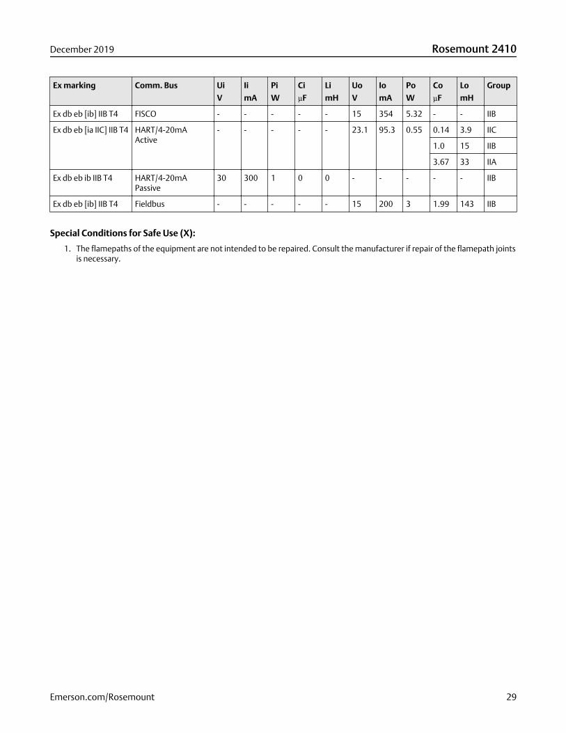
Ex marking Comm. Bus Ui
V
Ii
mA
Pi
W
Ci
µF
Li
mH
Uo
V
Io
mA
Po
W
Co
µF
Lo
mH
Group
Ex db eb [ib] IIB T4 FISCO - - - - - 15 354 5.32 - - IIB
Ex db eb [ia IIC] IIB T4 HART/4-20mAActive
- - - - - 23.1 95.3 0.55 0.14 3.9 IIC
1.0 15 IIB
3.67 33 IIA
Ex db eb ib IIB T4 HART/4-20mAPassive
30 300 1 0 0 - - - - - IIB
Ex db eb [ib] IIB T4 Fieldbus - - - - - 15 200 3 1.99 143 IIB
Special Conditions for Safe Use (X):
1. The flamepaths of the equipment are not intended to be repaired. Consult the manufacturer if repair of the flamepath jointsis necessary.
December 2019 Rosemount 2410
Emerson.com/Rosemount 29
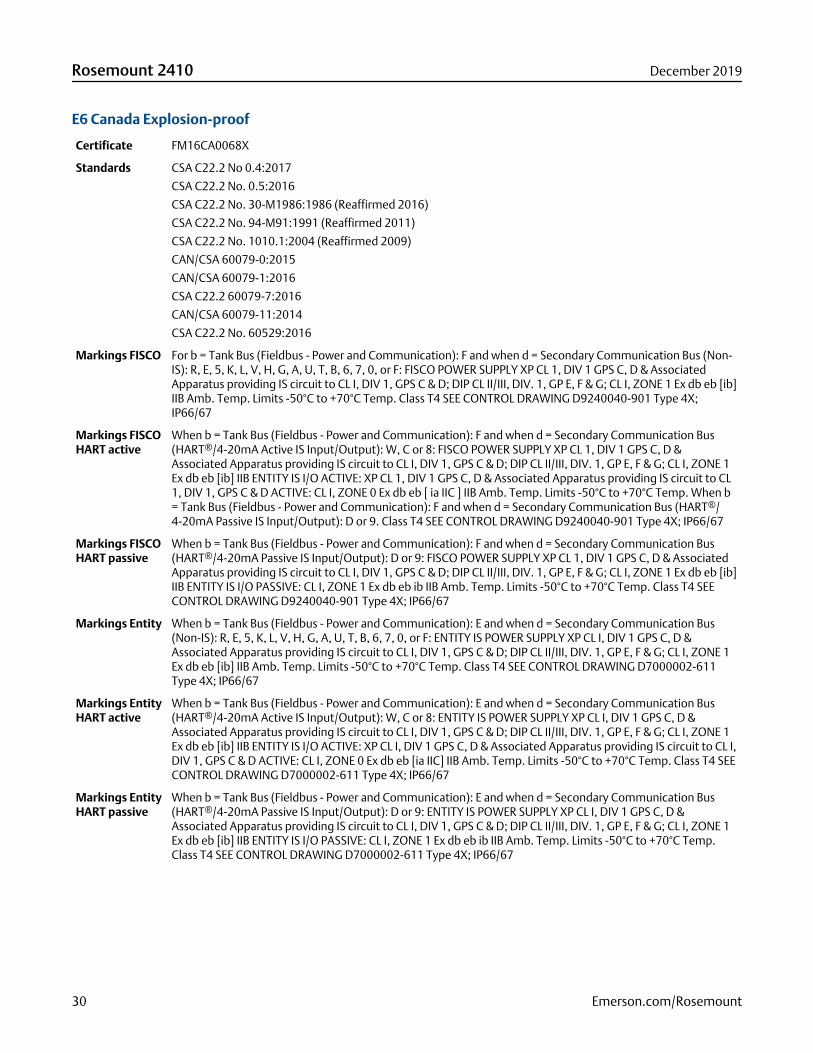
E6 Canada Explosion-proof
Certificate FM16CA0068X
Standards CSA C22.2 No 0.4:2017
CSA C22.2 No. 0.5:2016
CSA C22.2 No. 30-M1986:1986 (Reaffirmed 2016)
CSA C22.2 No. 94-M91:1991 (Reaffirmed 2011)
CSA C22.2 No. 1010.1:2004 (Reaffirmed 2009)
CAN/CSA 60079-0:2015
CAN/CSA 60079-1:2016
CSA C22.2 60079-7:2016
CAN/CSA 60079-11:2014
CSA C22.2 No. 60529:2016
Markings FISCO For b = Tank Bus (Fieldbus - Power and Communication): F and when d = Secondary Communication Bus (Non-IS): R, E, 5, K, L, V, H, G, A, U, T, B, 6, 7, 0, or F: FISCO POWER SUPPLY XP CL 1, DIV 1 GPS C, D & AssociatedApparatus providing IS circuit to CL I, DIV 1, GPS C & D; DIP CL II/III, DIV. 1, GP E, F & G; CL I, ZONE 1 Ex db eb [ib]IIB Amb. Temp. Limits -50°C to +70°C Temp. Class T4 SEE CONTROL DRAWING D9240040-901 Type 4X;IP66/67
Markings FISCOHART active
When b = Tank Bus (Fieldbus - Power and Communication): F and when d = Secondary Communication Bus(HART®/4-20mA Active IS Input/Output): W, C or 8: FISCO POWER SUPPLY XP CL 1, DIV 1 GPS C, D &Associated Apparatus providing IS circuit to CL I, DIV 1, GPS C & D; DIP CL II/III, DIV. 1, GP E, F & G; CL I, ZONE 1Ex db eb [ib] IIB ENTITY IS I/O ACTIVE: XP CL 1, DIV 1 GPS C, D & Associated Apparatus providing IS circuit to CL1, DIV 1, GPS C & D ACTIVE: CL I, ZONE 0 Ex db eb [ ia IIC ] IIB Amb. Temp. Limits -50°C to +70°C Temp. When b= Tank Bus (Fieldbus - Power and Communication): F and when d = Secondary Communication Bus (HART®/4-20mA Passive IS Input/Output): D or 9. Class T4 SEE CONTROL DRAWING D9240040-901 Type 4X; IP66/67
Markings FISCOHART passive
When b = Tank Bus (Fieldbus - Power and Communication): F and when d = Secondary Communication Bus(HART®/4-20mA Passive IS Input/Output): D or 9: FISCO POWER SUPPLY XP CL 1, DIV 1 GPS C, D & AssociatedApparatus providing IS circuit to CL I, DIV 1, GPS C & D; DIP CL II/III, DIV. 1, GP E, F & G; CL I, ZONE 1 Ex db eb [ib]IIB ENTITY IS I/O PASSIVE: CL I, ZONE 1 Ex db eb ib IIB Amb. Temp. Limits -50°C to +70°C Temp. Class T4 SEECONTROL DRAWING D9240040-901 Type 4X; IP66/67
Markings Entity When b = Tank Bus (Fieldbus - Power and Communication): E and when d = Secondary Communication Bus(Non-IS): R, E, 5, K, L, V, H, G, A, U, T, B, 6, 7, 0, or F: ENTITY IS POWER SUPPLY XP CL I, DIV 1 GPS C, D &Associated Apparatus providing IS circuit to CL I, DIV 1, GPS C & D; DIP CL II/III, DIV. 1, GP E, F & G; CL I, ZONE 1Ex db eb [ib] IIB Amb. Temp. Limits -50°C to +70°C Temp. Class T4 SEE CONTROL DRAWING D7000002-611Type 4X; IP66/67
Markings EntityHART active
When b = Tank Bus (Fieldbus - Power and Communication): E and when d = Secondary Communication Bus(HART®/4-20mA Active IS Input/Output): W, C or 8: ENTITY IS POWER SUPPLY XP CL I, DIV 1 GPS C, D &Associated Apparatus providing IS circuit to CL I, DIV 1, GPS C & D; DIP CL II/III, DIV. 1, GP E, F & G; CL I, ZONE 1Ex db eb [ib] IIB ENTITY IS I/O ACTIVE: XP CL I, DIV 1 GPS C, D & Associated Apparatus providing IS circuit to CL I,DIV 1, GPS C & D ACTIVE: CL I, ZONE 0 Ex db eb [ia IIC] IIB Amb. Temp. Limits -50°C to +70°C Temp. Class T4 SEECONTROL DRAWING D7000002-611 Type 4X; IP66/67
Markings EntityHART passive
When b = Tank Bus (Fieldbus - Power and Communication): E and when d = Secondary Communication Bus(HART®/4-20mA Passive IS Input/Output): D or 9: ENTITY IS POWER SUPPLY XP CL I, DIV 1 GPS C, D &Associated Apparatus providing IS circuit to CL I, DIV 1, GPS C & D; DIP CL II/III, DIV. 1, GP E, F & G; CL I, ZONE 1Ex db eb [ib] IIB ENTITY IS I/O PASSIVE: CL I, ZONE 1 Ex db eb ib IIB Amb. Temp. Limits -50°C to +70°C Temp.Class T4 SEE CONTROL DRAWING D7000002-611 Type 4X; IP66/67
Rosemount 2410 December 2019
30 Emerson.com/Rosemount
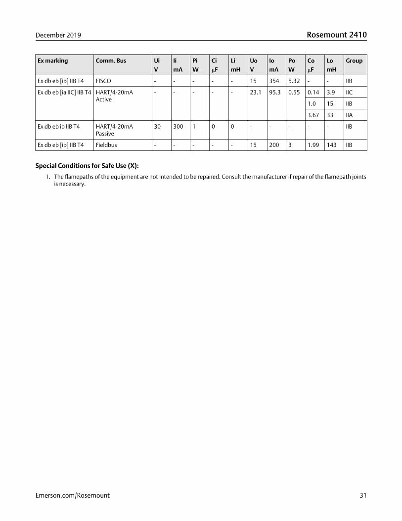
Ex marking Comm. Bus Ui
V
Ii
mA
Pi
W
Ci
µF
Li
mH
Uo
V
Io
mA
Po
W
Co
µF
Lo
mH
Group
Ex db eb [ib] IIB T4 FISCO - - - - - 15 354 5.32 - - IIB
Ex db eb [ia IIC] IIB T4 HART/4-20mAActive
- - - - - 23.1 95.3 0.55 0.14 3.9 IIC
1.0 15 IIB
3.67 33 IIA
Ex db eb ib IIB T4 HART/4-20mAPassive
30 300 1 0 0 - - - - - IIB
Ex db eb [ib] IIB T4 Fieldbus - - - - - 15 200 3 1.99 143 IIB
Special Conditions for Safe Use (X):
1. The flamepaths of the equipment are not intended to be repaired. Consult the manufacturer if repair of the flamepath jointsis necessary.
December 2019 Rosemount 2410
Emerson.com/Rosemount 31
Europe
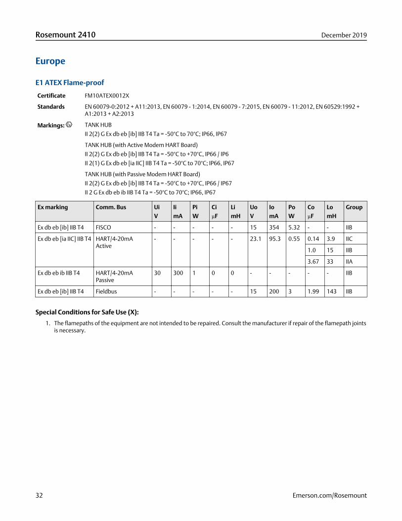
E1 ATEX Flame-proof
Certificate FM10ATEX0012X
Standards EN 60079-0:2012 + A11:2013, EN 60079 - 1:2014, EN 60079 - 7:2015, EN 60079 - 11:2012, EN 60529:1992 +A1:2013 + A2:2013
Markings: TANK HUB
II 2(2) G Ex db eb [ib] IIB T4 Ta = -50°C to 70°C; IP66, IP67
TANK HUB (with Active Modem HART Board)
II 2(2) G Ex db eb [ib] IIB T4 Ta = -50°C to +70°C, IP66 / IP6
II 2(1) G Ex db eb [ia IIC] IIB T4 Ta = -50°C to 70°C; IP66, IP67
TANK HUB (with Passive Modem HART Board)
II 2(2) G Ex db eb [ib] IIB T4 Ta = -50°C to +70°C, IP66 / IP67
II 2 G Ex db eb ib IIB T4 Ta = -50°C to 70°C; IP66, IP67
Ex marking Comm. Bus Ui
V
Ii
mA
Pi
W
Ci
µF
Li
mH
Uo
V
Io
mA
Po
W
Co
µF
Lo
mH
Group
Ex db eb [ib] IIB T4 FISCO - - - - - 15 354 5.32 - - IIB
Ex db eb [ia IIC] IIB T4 HART/4-20mAActive
- - - - - 23.1 95.3 0.55 0.14 3.9 IIC
1.0 15 IIB
3.67 33 IIA
Ex db eb ib IIB T4 HART/4-20mAPassive
30 300 1 0 0 - - - - - IIB
Ex db eb [ib] IIB T4 Fieldbus - - - - - 15 200 3 1.99 143 IIB
Special Conditions for Safe Use (X):
1. The flamepaths of the equipment are not intended to be repaired. Consult the manufacturer if repair of the flamepath jointsis necessary.
Rosemount 2410 December 2019
32 Emerson.com/Rosemount

International
E7 IECEx Flame-proof
Certificate IECEx FMG 10.0005X
Standards IEC 60079-0:2011
IEC 60079-1:2014
IEC 60079-7:2015
IEC 60079-11:2011
Markings Ex db eb [ib] IIB T4 Ta = -50 ºC to 70 ºC; FISCO
or
Ex db eb [ib] IIB T4 Ta = -50 ºC to 70 ºC; FISCO and
Ex db eb [ia IIC] IIB T4 Ta = -50 ºC to 70 ºC Entity
or
Ex db eb [ib] IIB T4 Ta = -50 ºC to 70 ºC; FISCO and
Ex db eb ib IIB T4 Ta = -50 ºC to 70 ºC Entity
or
Ex db eb ib IIB T4 Ta = -50 ºC to 70 ºC Entity
or
Ex db eb ib IIB T4 Ta = -50 ºC to 70 ºC Entity and
Ex db eb [ia IIC] IIB T4 Ta = -50 ºC to 70 ºC Entity
or
Ex db eb [ib] IIB T4 Ta = -50 ºC to 70 ºC Entity and
Ex db eb ib IIB T4 Ta = -50 ºC to 70 ºC Entity
IP66; IP67
Special Conditions for Safe Use (X):
1. The flamepaths of the equipment are not intended to be repaired. Consult the manufacturer if repair of the flamepath jointsis necessary.
Ex marking Comm. Bus Ui
V
Ii
mA
Pi
W
Ci
µF
Li
mH
Uo
V
Io
mA
Po
W
Co
µF
Lo
mH
Group
Ex db eb [ib] IIB T4Gb
FISCO - - - - - 15 354 5.32 - - IIB
Ex db eb [ia IIC Ga]IIB T4 Gb
HART/4-20mAActive
- - - - - 23.1 95.3 0.55 0.14 3.9 IIC
1.0 15 IIB
3.67 33 IIA
Ex db eb ib IIB T4 Gb HART/4-20mAPassive
30 300 1 0 0 - - - - - IIB
Ex db eb [ib] IIB T4Gb
Fieldbus - - - - - 15 200 3 1.99 143 IIB
December 2019 Rosemount 2410
Emerson.com/Rosemount 33

Brazil
E2 INMETRO Flame-proof
Certificate UL-BR 17.1017X
Standards ABNT NBR IEC 60079-0:2013, ABNT NBR IEC 60079-1:2016, ABNT NBR IEC 60079-7:2008, ABNT NBR IEC60079-11:2013
Markings Ex db e [ib] IIB T4 Gb
Ex db e [ia IIC] IIB T4 Gb
Ex db e ib IIB T4 Gb
Tamb= -50 °C a +70 °C
IP66/IP67
Special Conditions for Safe Use (X):
1. See certificate for special conditions.
Ex marking Comm. Bus Ui
V
Ii
mA
Pi
W
Ci
µF
Li
mH
Uo
V
Io
mA
Po
W
Co
µF
Lo
mH
Group
Ex db e [ib] IIB T4 Gb FISCO - - - - - 15 354 5.32 - - IIB
Ex db e [ia IIC Ga] IIBT4 Gb
HART/4-20mAActive
- - - - - 23.1 95.3 0.55 0.14 3.9 IIC
1.0 15 IIB
3.67 33 IIA
Ex db e ib IIB T4 Gb HART/4-20mAPassive
30 300 1 0 0 - - - - - IIB
Ex db e [ib] IIB T4 Gb Fieldbus - - - - - 15 200 3 1.99 143 IIB
Rosemount 2410 December 2019
34 Emerson.com/Rosemount
China
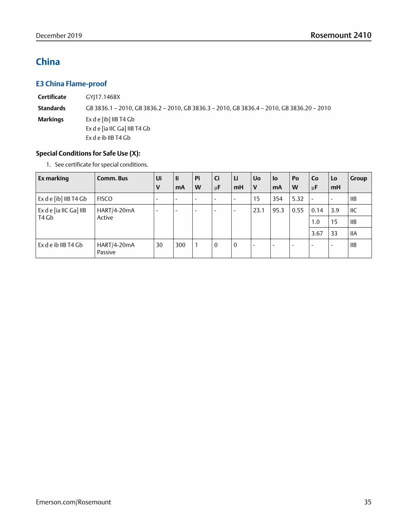
E3 China Flame-proof
Certificate GYJ17.1468X
Standards GB 3836.1 – 2010, GB 3836.2 – 2010, GB 3836.3 – 2010, GB 3836.4 – 2010, GB 3836.20 – 2010
Markings Ex d e [ib] IIB T4 Gb
Ex d e [ia IIC Ga] IIB T4 Gb
Ex d e ib IIB T4 Gb
Special Conditions for Safe Use (X):
1. See certificate for special conditions.
Ex marking Comm. Bus Ui
V
Ii
mA
Pi
W
Ci
µF
Li
mH
Uo
V
Io
mA
Po
W
Co
µF
Lo
mH
Group
Ex d e [ib] IIB T4 Gb FISCO - - - - - 15 354 5.32 - - IIB
Ex d e [ia IIC Ga] IIBT4 Gb
HART/4-20mAActive
- - - - - 23.1 95.3 0.55 0.14 3.9 IIC
1.0 15 IIB
3.67 33 IIA
Ex d e ib IIB T4 Gb HART/4-20mAPassive
30 300 1 0 0 - - - - - IIB
December 2019 Rosemount 2410
Emerson.com/Rosemount 35
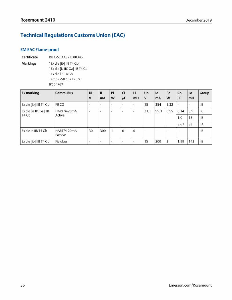
Technical Regulations Customs Union (EAC)
EM EAC Flame-proof
Certificate RU C-SE.AA87.B.00345
Markings 1Ex d e [ib] IIB T4 Gb
1Ex d e [ia IIC Ga] IIB T4 Gb
1Ex d e llB T4 Gb
Tamb= -50 °C a +70 °C
IP66/IP67
Ex marking Comm. Bus Ui
V
Ii
mA
Pi
W
Ci
µF
Li
mH
Uo
V
Io
mA
Po
W
Co
µF
Lo
mH
Group
Ex d e [ib] IIB T4 Gb FISCO - - - - - 15 354 5.32 - - IIB
Ex d e [ia IIC Ga] IIBT4 Gb
HART/4-20mAActive
- - - - - 23.1 95.3 0.55 0.14 3.9 IIC
1.0 15 IIB
3.67 33 IIA
Ex d e ib IIB T4 Gb HART/4-20mAPassive
30 300 1 0 0 - - - - - IIB
Ex d e [ib] IIB T4 Gb Fieldbus - - - - - 15 200 3 1.99 143 IIB
Rosemount 2410 December 2019
36 Emerson.com/Rosemount
Japan
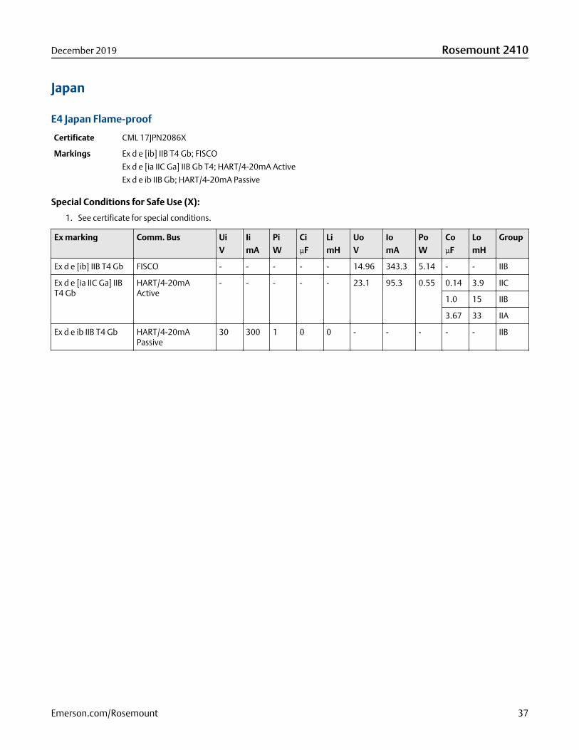
E4 Japan Flame-proof
Certificate CML 17JPN2086X
Markings Ex d e [ib] IIB T4 Gb; FISCO
Ex d e [ia IIC Ga] IIB Gb T4; HART/4-20mA Active
Ex d e ib IIB Gb; HART/4-20mA Passive
Special Conditions for Safe Use (X):
1. See certificate for special conditions.
Ex marking Comm. Bus Ui
V
Ii
mA
Pi
W
Ci
µF
Li
mH
Uo
V
Io
mA
Po
W
Co
µF
Lo
mH
Group
Ex d e [ib] IIB T4 Gb FISCO - - - - - 14.96 343.3 5.14 - - IIB
Ex d e [ia IIC Ga] IIBT4 Gb
HART/4-20mAActive
- - - - - 23.1 95.3 0.55 0.14 3.9 IIC
1.0 15 IIB
3.67 33 IIA
Ex d e ib IIB T4 Gb HART/4-20mAPassive
30 300 1 0 0 - - - - - IIB
December 2019 Rosemount 2410
Emerson.com/Rosemount 37
Republic of Korea
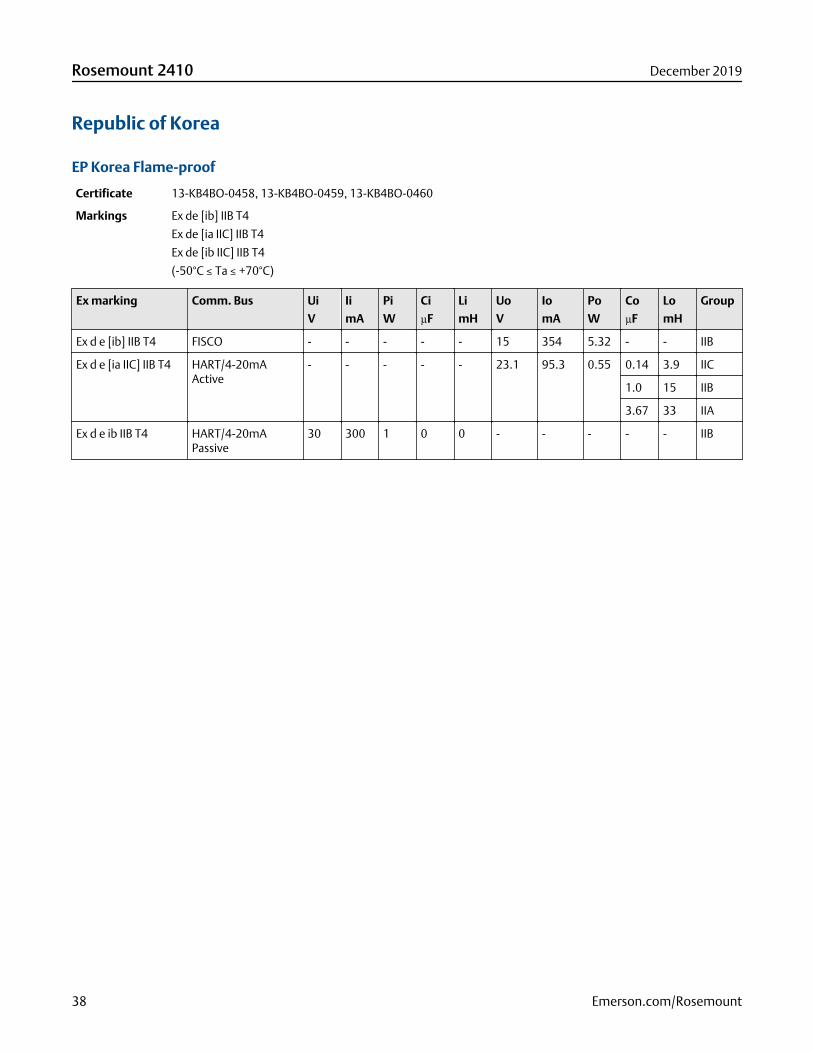
EP Korea Flame-proof
Certificate 13-KB4BO-0458, 13-KB4BO-0459, 13-KB4BO-0460
Markings Ex de [ib] IIB T4
Ex de [ia IIC] IIB T4
Ex de [ib IIC] IIB T4
(-50°C ≤ Ta ≤ +70°C)
Ex marking Comm. Bus Ui
V
Ii
mA
Pi
W
Ci
µF
Li
mH
Uo
V
Io
mA
Po
W
Co
µF
Lo
mH
Group
Ex d e [ib] IIB T4 FISCO - - - - - 15 354 5.32 - - IIB
Ex d e [ia IIC] IIB T4 HART/4-20mAActive
- - - - - 23.1 95.3 0.55 0.14 3.9 IIC
1.0 15 IIB
3.67 33 IIA
Ex d e ib IIB T4 HART/4-20mAPassive
30 300 1 0 0 - - - - - IIB
Rosemount 2410 December 2019
38 Emerson.com/Rosemount

India
EW CCOE Flame-proof
Certificate P380588/1
Markings Ex d e [ib] IIB T4 Gb
Ex d e [ia IIC Ga] IIB T4 Gb
Ex d e ib IIB T4 Gb
Ex marking Comm. Bus Ui
V
Ii
mA
Pi
W
Ci
µF
Li
mH
Uo
V
Io
mA
Po
W
Co
µF
Lo
mH
Group
Ex d e [ib] IIB T4 Gb FISCO - - - - - 15 354 5.32 - - IIB
Ex d e [ia IIC Ga] IIBT4 Gb
HART/4-20mAActive
- - - - - 23.1 95.3 0.55 0.14 3.9 IIC
1.0 15 IIB
3.67 33 IIA
Ex d e ib IIB T4 Gb HART/4-20mAPassive
30 300 1 0 0 - - - - - IIB
Ex d e [ib] IIB T4 Gb Fieldbus - - - - - 15 200 3 1.99 143 IIB
December 2019 Rosemount 2410
Emerson.com/Rosemount 39

Additional certifications
Safety Certification (SIS)
3 Functional Safety
Certificate ROS 1312032 C001
SIL 3 2-in-1 (1oo2) option (SIS-relays)
Standards IEC 61508:2010 Parts 1-7
S Functional Safety
Certificate ROS 1312032 C004
SIL 2 1-in-1 (1oo1) option, with 4-20mA or K1/K2 relay
Standards IEC 61508:2010 Parts 1-7
Certificate ROS 1312032 C005
SIL 2 2-in-1 (1oo1) option, with 4-20mA or K1/K2 relay
Standards IEC 61508:2010 Parts 1-7
Rosemount 2410 December 2019
40 Emerson.com/Rosemount
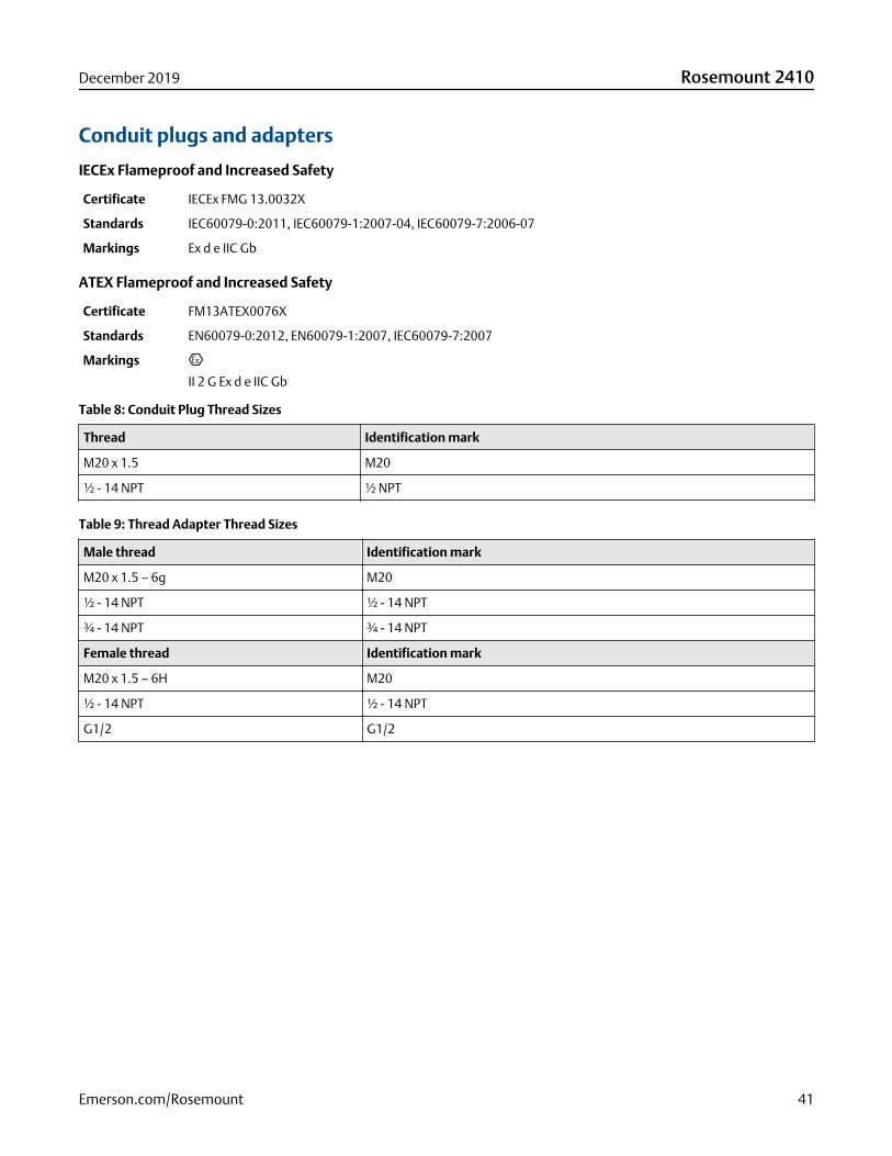
Conduit plugs and adapters
IECEx Flameproof and Increased Safety
Certificate IECEx FMG 13.0032X
Standards IEC60079-0:2011, IEC60079-1:2007-04, IEC60079-7:2006-07
Markings Ex d e IIC Gb
ATEX Flameproof and Increased Safety
Certificate FM13ATEX0076X
Standards EN60079-0:2012, EN60079-1:2007, IEC60079-7:2007
Markings
II 2 G Ex d e IIC Gb
Table 8: Conduit Plug Thread Sizes
Thread Identification mark
M20 x 1.5 M20
½ - 14 NPT ½ NPT
Table 9: Thread Adapter Thread Sizes
Male thread Identification mark
M20 x 1.5 – 6g M20
½ - 14 NPT ½ - 14 NPT
¾ - 14 NPT ¾ - 14 NPT
Female thread Identification mark
M20 x 1.5 – 6H M20
½ - 14 NPT ½ - 14 NPT
G1/2 G1/2
December 2019 Rosemount 2410
Emerson.com/Rosemount 41
Product certifications for Emerson 775 THUM AdapterExtract from Emerson 775 THUM Adapter Product Certifications Rev 2.6
For more information, see the Emerson Wireless 775 THUM Adapter Product Data Sheet.
European directive informationA copy of the EU Declaration of Conformity can be found at the end of the Quick Start Guide. The most recent revision of the EUDeclaration of Conformity can be found at Emerson.com/Rosemount.
Ordinary location certification from FM ApprovalsAs standard, the transmitter has been examined and tested to determine that the design meets the basic electrical, mechanical,and fire protection requirements by FM Approvals, a nationally recognized test laboratory (NRTL) as accredited by the FederalOccupational Safety and Health Administration (OSHA).
Telecommunication compliance (for wireless products only)All wireless devices require certification to ensure that they adhere to regulations regarding the use of the RF spectrum. Nearlyevery country requires this type of product certification.
Emerson is working with governmental agencies around the world to supply fully compliant products and remove the risk ofviolating country directives or laws governing wireless device usage.
FCC and IC (for wireless products only)This device complies with Part 15 of the FCC Rules. Operation is subject to the following conditions: This device may not causeharmful interference. This device must accept any interference received, including interference that may cause undesiredoperation. This device must be installed to ensure a minimum antenna separation distance of 20 cm from all persons.
Installing equipment in North AmericaThe US National Electrical Code® (NEC) and the Canadian Electrical Code (CEC) permit the use of Division marked equipment inZones and Zone marked equipment in Divisions. The markings must be suitable for the area classification, gas, and temperatureclass. This information is clearly defined in the respective codes.
USA
I5 USA Intrinsically Safe (IS) and Non-incendive
Certificate 3036224
Standards FM Class 3600 - 1998, FM Class 3610 - 2007, FM Class 3611 - 2004, FM Class 3810 - 2005, NEMA 250 - 2003,IEC 60529 - 2004
Markings IS CL I, DIV 1, GP A, B, C, D; CL II, DIV 1, GP E, F, G; Class III; Class 1, Zone 0, AEx ia IIC T4; NI CL I, DIV 2, GP A, B,C, D T4; T4(–50 °C≤ Ta ≤ +70 °C) when connected per Rosemount drawing 00775-0010; Type 4X/IP66
Rosemount 2410 December 2019
42 Emerson.com/Rosemount

Canada
I6 Canada Intrinsically Safe
Certificate 2174201
Standards CAN/CSA C22.2 No. 0-M91 (R2001), CAN/CSA C22.2 No. 94-M91 (R2001), CSA Std C22.2 No. 142-M1987,CAN/CSA C22.2 No.157-92, CSA Std C22.2 No. 213-M1987, C22.2 No. 60529
Markings Intrinsically Safe Class I, Division 1, Groups A, B, C, D T3C; Suitable for use in Class I, Division 2, Groups A, B, C, DT3C; T3C(–50 °C≤ Ta ≤ +70 °C) when installed per Rosemount drawing 00775-0012; Type 4X/IP66
Europe
I1 ATEX Intrinsic Safety
Certificate Baseefa09ATEX0125X
Standards IEC 60079-0:2011; EN60079-11:2012;
Markings II 1G Ex ia IIC T4 Ga, T4(–50 °C≤ Ta ≤ +70 °C)
Special Conditions for Safe Use (X):
1. The surface resistivity of the antenna is greater than 1GΩ. To avoid electrostatic charge build-up, it must not be rubbed orcleaned with solvents or dry cloth.
2. The Rosemount 775 enclosure may be made of aluminum alloy and given a protective polyurethane paint finish; however,care should be taken to protect it from impact or abrasion if located in zone 0.
N1 ATEX Type n
Certificate Baseefa09ATEX0131
Standards IEC 60079-0:2012 + A11:2013, EN 60079-15:2010;
Markings II 3G Ex nA IIC T4 Gc, T4(–50 °C≤ Ta ≤ +70 °C) IP66
International
I7 IECEx Intrinsic Safety
Certificate IECEx BAS 09.0050X
Standards IEC 60079-0:2011, IEC 60079-11:2011
Markings Ex ia IIC T4 Ga, T4(–50 °C≤ Ta ≤ +70 °C) IP66
Special Conditions for Safe Use (X):
1. The surface resistivity of the antenna is greater than 1 GΩ. To avoid electrostatic charge build-up, it must not be rubbed orcleaned with solvents or dry cloth.
2. The Rosemount 775 enclosure may be made of aluminum alloy and given a protective polyurethane paint finish; however,care should be taken to protect it from impact or abrasion if located in zone 0.
December 2019 Rosemount 2410
Emerson.com/Rosemount 43

N7 IECEx Type n
Certificate IECEx BAS 09.0058
Standards IEC 60079-0:2011, IEC 60079-15:2010;
Markings Ex nA IIC T4 Gc, T4(–50 °C≤ Ta ≤ +70 °C) IP66
Brazil
I2 INMETRO Intrinsic Safety
Certificate UL-BR 15.0089X
Standards ABNT NBR IEC 60079-0:2013, ABNT NBR IEC 60079-11:2013
Markings Ex ia IIC T4 Ga (–50 °C≤ Ta ≤ +70 °C), IP66
Special Conditions for Safe Use (X):
1. The surface resistivity of the antenna is greater than 1 GΩ. To avoid electrostatic charge build-up, it must not be rubbed orcleaned with solvents or dry cloth.
2. The enclosure may be made of aluminum alloy and given a protective polyurethane paint finish; special care must be takento minimize the risk of impact or friction of the housing which can cause the generation of sparks.
N2 INMETRO Type n
Certificate UL-BR 15.0027
Standards ABNT NBR IEC 60079-0:2008 + Errata 1:2011, IEC 60079-15:2012
Markings Ex nA IIC T4 Gc (–50 °C≤ Ta ≤ +70 °C) IP66
China
I3 NEPSI Intrinsic Safety
Certificate GYJ19.1371X
Standards GB3836.1 – 2010, GB3836.4 – 2010, GB3836.20-2010
Markings Ex ia IIC T4 Ga, –50 ~ +70 °C
Special Conditions for Safe Use (X):
1. See certificate for special conditions.
Japan
I4 TIIS Intrinsically Safe
Certificate TC22150X
Markings Ex ia IIB T4 Ga, –50 ~ +70 °C
Rosemount 2410 December 2019
44 Emerson.com/Rosemount
Special Conditions for Safe Use (X):
1. See certificate for special conditions.
EAC - Belarus, Kazakhstan, Russia
IM Technical Regulation Customs Union (EAC) Intrinsic Safety
Certificate TC RU C-US.AA87.B.00993
Markings 0Ex ia IIC T4 Ga X; T4 (–50 °C≤ Ta ≤ +70 °C) IP66
Special Conditions for Safe Use (X):
1. See certificate for special conditions.
Republic of Korea
IP Korea (KOSHA) Intrinsic Safety
Certificate 10-KB4BO-0010X
Markings Ex ia IIC T4
Special Conditions for Safe Use (X):
1. See certificate for special conditions.
India
IW India (CCOE) Intrinsic Safety
Certificates A/P/HQ/MH/104/4259(P366317)
Markings Ex ia IIC T4
December 2019 Rosemount 2410
Emerson.com/Rosemount 45

Dimensional drawingsFigure 13: Rosemount 2410 Tank Hub Dimensions
220 (8.7) 260 (10.2)
170 (6.7)
Dimensions are in millimeters (inches).
Figure 14: Rosemount 2410 Tank Hub Mounting
Rosemount 2410 can be mounted on a wall or a pipe with 33.4-60.3 mm (1-2 in.) diameter.
Figure 15: Emerson Wireless 775 THUM Adapter Assembly Dimensions
82 (3.2)
106 (4.2)
122 (4.8)
30 (1.2)
145 (5.7)
120 (4.7)
Dimensions are in millimeters (inches).
Rosemount 2410 December 2019
46 Emerson.com/Rosemount
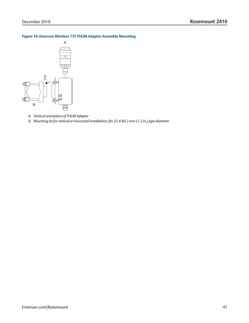
Figure 16: Emerson Wireless 775 THUM Adapter Assembly Mounting
A
B
A. Vertical orientation of THUM AdapterB. Mounting kit for vertical or horizontal installation; fits 33.4-60.3 mm (1-2 in.) pipe diameter
December 2019 Rosemount 2410
Emerson.com/Rosemount 47

00813-0100-2410Rev. BA
December 2019
Global Headquarters and Europe RegionalOffice Tank GaugingEmerson Automation SolutionsBox 150(Visiting address: Layoutvägen 1)SE-435 23 MölnlyckeSweden
+46 31 337 00 00
+46 31 25 30 22
North America Regional Office TankGaugingEmerson Automation Solutions6005 Rogerdale RoadMail Stop NC 136Houston, TX 77072, USA
+1 281 988 4000 or +1 800 722 2865
Latin America Regional OfficeEmerson Automation Solutions1300 Concord Terrace, Suite 400Sunrise, FL 33323, USA
+1 954 846 5030
+1 954 846 5121
Asia Pacific Regional OfficeEmerson Automation Solutions1 Pandan CrescentSingapore 128461
+65 6777 8211
+65 6777 0947
Middle East and Africa Regional OfficeEmerson Automation SolutionsEmerson FZEP.O. Box 17033Jebel Ali Free Zone - South 2Dubai, United Arab Emirates
+971 4 8118100
+971 4 8865465
Linkedin.com/company/Emerson-Automation-Solutions
Twitter.com/Rosemount_News
Facebook.com/Rosemount
Youtube.com/user/RosemountMeasurement
©2019 Emerson. All rights reserved.
Emerson Terms and Conditions of Sale are available upon request. The Emerson logo is atrademark and service mark of Emerson Electric Co. Rosemount is a mark of one of theEmerson family of companies. All other marks are the property of their respective owners.
![[AUTOVALUTAZIONE DEI PROCESSI INTERNI] - Fisco e Tasse...Fisco, strumenti di calcolo per un fisco semplice Keywords: fisco, tool, software calcolo fisco, tool calcolo fisco, fiscoetasse](https://img.dokumen.tips/doc/110x75/605505b6b3773e07795a7b4a/autovalutazione-dei-processi-interni-fisco-e-tasse-fisco-strumenti-di-calcolo.jpg)