Embed Size (px)
Citation preview

November 23, 2021
Dear Prospective Quoter:
SUBJECT: Solicitation 19EG3022Q0001 for Upgrade government owned properties.
The Embassy of the United States of America invites you to submit a quotation for Repair & Upgrade
US government owned properties, residential and non-residential properties.
Submit your quotation by e-mail to [email protected] on or before 2:00 pm on December 9,
2021. No quotations will be accepted after this time.
In order for a quotation to be considered, you must also complete and submit the following:
1. SF-1449
2. Section 1, Pricing
3. Section 5, Representations and Certifications and ensure compliance with FAR 52.229-11 is completed
with IRS Form W-14 found at www.irs.goc/w14
4. Additional information as required in Section 3
Direct any questions regarding this Solicitation to [email protected], mentioning the solicitation
number and description in the email subject deadline to receive solicitation questions is on or before COB
December 2, 2021.
1

TABLE OF CONTENTS
Section 1 - The Schedule
• SF 1449 cover sheet
• Continuation To SF-1449, RFQ Number 19EG3022Q0001, Prices, Block 23
• Continuation To SF-1449, RFQ Number 19EG3022Q0001, Schedule OfSupplies/Services, Block 20 Description/Specifications/Work Statement
• Attachment 1 to Description/Specifications/Performance Work Statement,Government Furnished Property
Section 2 - Contract Clauses
• Contract Clauses• Addendum to Contract Clauses - FAR and DOSAR Clauses not Prescribed in Part 12
Section 3 - Solicitation Provisions
• Solicitation Provisions• Addendum to Solicitation Provisions - FAR and DOSAR Provisions not Prescribed in
Part 12
Section 4 - Evaluation Factors
• Evaluation Factors• Addendum to Evaluation Factors - FAR and DOSAR Provisions not Prescribed in
Part 12
Section 5 - Representations and Certifications
• Offeror Representations and Certifications• Addendum to Offeror Representations and Certifications - FAR and DOSAR
Provisions not Prescribed in Part 12
2

AUTORIZED FOR LOCAL REPRODUCTION STANDARD FORM 1449 (REV. 02/2012) PREVIOUS EDITION IS NOT USABLE Computer Generated Prescribed by GSA - FAR (48 CFR) 53.212
SOLICITATION/CONTRACT/ORDER FOR COMMERCIAL ITEMSOFFEROR TO COMPLETE BLOCKS 12, 17, 23, 24, & 30
1. REQUISITION NUMBERPR10318732
PAGE 1 OF 197 PAGES
2. CONTRACT NO. 3. AWARD/ EFFECTIVE DATE
4. ORDER NUMBER 5. SOLICITATION NUMBER 19EG3022Q0001
6. SOLICITATION ISSUE DATE 11/23/2021
7. FOR SOLICITATION INFORMATION CALL:
a. NAME Tamer Daoud
b. TELEPHONE NUMBER(No collect calls)
8. OFFER DUE DATE/LOCAL TIME12/09/2021 / 14:00
9. ISSUED BY CODE EG300 10. THIS ACQUISITION IS UNRESTRICTED OR SET ASIDE: % FOR:
SMALL BUSINESS WOMEN-OWNED SMALL BUSINESS
HUBZONE SMALL BUSINESS
(WOSB) ELLIGIBLE UNDER THE WOMEN-OWNED SMALL BUSINESS PROGRAM NAICS:
EDWOSB EMERGING SMALL BUSINESS
AMERICAN EMBASSY CAIROUS EMBASSY CAIRO 8 KAMAL EL DIN SALAH, ATTN: PROCUREMENT/CONTRACTING OFFICECAIRO 11519EGYPT
SERVICE-DISABLED VETERAN-OWNED SMALL BUSINESS 8 (A) SIZE STANDARD:
13b. RATING11. DELIVERY FOR FOB DESTINAT-TION UNLESS BLOCK ISMARKED
SEE SCHEDULE
12. DISCOUNT TERMS 13a. THIS CONTRACT IS A RATED ORDER UNDER DPAS (15 CFR 700)
14. METHOD OF SOLICITATION
x RFQ IFB RFP
15. DELIVER TO CODE 16. ADMINISTERED BY CODEAMERICAN EMBASSY CAIROUS EMBASSY CAIRO 8 KAMAL EL DIN SALAH, ATTN: SPM RECEIVING OFFICECAIRO 11519EGYPT
AMERICAN EMBASSY CAIROUS EMBASSY CAIRO 8 KAMAL EL DIN SALAH, ATTN: PROCUREMENT/CONTRACTING OFFICECAIRO 11519EGYPT
CODE FACILITY CODE
17a. CONTRACTOR/ OFFERER
TELEPHONE NO.
18a. PAYMENT WILL BE MADE BY AMERICAN EMBASSY CAIROUS EMBASSY CAIRO 8 KAMAL EL DIN SALAH, ATTN: FINANCIAL MANAGEMENT OFFICE - DBOCAIRO 11519
EGYPT
CODE
17b. CHECK IF REMITTANCE IS DIFFERENT AND PUT SUCH ADDRESS IN OFFER
18b. SUBMIT INVOICES TO ADDRESS SHOWN IN BLOCK 18a UNLESS BLOCK BELOW IS CHECKED SEE ADDENDUM
19.ITEM NO.
20.SCHEDULE OF SUPPLIES/SERVICES
21.QUANTITY
22.UNIT
23.UNIT PRICE
24.AMOUNT
(Use Reverse and/or Attach Additional Sheets as Necessary)
25. ACCOUNTING AND APPROPRIATION DATA 26. TOTAL AWARD AMOUNT (For Govt. Use Only)
27a.SOLICITATION INCORPORATES BY REFERENCE FAR 52.212-1, 52.212-4. FAR 52.212-3 AND 52.212-5 ARE ATTACHED. ADDENDA ARE ARE NOT ATTACHED
27b.CONTRACT/PURCHASE ORDER INCORPORATES BY REFERENCE FAR 52.212-4. FAR 52.212-5 IS ATTACHED. ADDENDA ARE ARE NOT ATTACHED
28. CONTRACTOR IS REQUIRED TO SIGN THIS DOCUMENT AND RETURN _ __ COPIES TO ISSUING OFFICE. CONTRACTOR AGREES TO FURNISH AND DELIVER ALL ITEMS SET FORTH OR OTHERWISE IDENTIFIED ABOVE AND ON ANY ADDITIONAL SHEETS SUBJECT TO THE TERMS AND CONDITIONS SPECIFIED HEREIN.
29. AWARD OF CONTRACT: REF. _ _______________ OFFER DATED_ __________. YOUR OFFER ON SOLICITATION (BLOCK 5), INCLUDING ANYADDITIONS OR CHANGES WHICH ARE SET FORTH HEREIN, IS ACCEPTED AS
TO ITEMS:
30a. SIGNATURE OF OFFEROR/CONTRACTOR 31a. UNITED STATES OF AMERICA (SIGNATURE OF CONTRACTING OFFICER)
30b. NAME AND TITLE OF SIGNER (Type or print) 30c. DATE SIGNED 31b. NAME OF CONTRACTING OFFICER (Type or print) 31c. DATE SIGNED
3

ITEM NO. 20.SCHEDULE OF SUPPLIES/SERVICES
21.QUANTITY
22.UNIT
23.UNIT PRICE
24.AMOUNT
32a. QUANTITY IN COLUMN 21 HAS BEEN
RECEIVED INSPECTED ACCEPTED, AND CONFORMS TO THE CONTRACT, EXCEPT AS NOTED: _______________________________
32b. SIGNATURE OF AUTHORIZED GOVERNMENT REPRESENTATIVE
32c. DATE 32d. PRINTED NAME AND TITLE OF AUTHORIZED GOVERNMENT REPRESENTATIVE
32e. MAILING ADDRESS OF AUTHORIZED GOVERNMENT REPRESENTATIVE 32f. TELEPHONE NUMBER OF AUTHORIZED GOVERNMENT REPRESENTATIVE
32g. E-MAIL OF AUTHORIZED GOVERNMENT REPRESENTATIVE
33. SHIP NUMBER 34. VOUCHER NUMBER 35. AMOUNT VERIFIEDCORRECT FOR
36. PAYMENT 37. CHECK NUMBER
PARTIAL FINAL COMPLETE PARTIAL FINAL38. S/R ACCOUNT NO. 39. S/R VOUCHER NO. 40. PAID BY
41.a. I CERTIFY THIS ACCOUNT IS CORRECT AND PROPER FOR PAYMENT 42a. RECEIVED BY (Print) 41b. SIGNATURE AND TITLE OF CERTIFYING OFFICER 41C. DATE
42b. RECEIVED AT (Location)
42c. DATE REC’D (YY/MM/DD) 42d. TOTAL CONTAINERS
STANDARD FORM 1449 (REV. 2/2012) BACK
4

SECTION 1 - THE SCHEDULE
CONTINUATION TO SF-1449 RFQ NUMBER 19EG3022Q0001
PRICES, BLOCK 23
NOTE: Add the below to the SF-1449:
JAMES ZADROGA 9/11 VICTIMS HEALTH AND COMPENSATION ACT OF 2010 NOTICE: UNLESS A WAIVER OR EXCEPTION APPLIES, PAYMENTS SUBSEQUENT TO THIS PROCUREMENT ARE SUBJECT TO AN EXCISE TAX OF 2% PERSUANT TO 26 U.S.C. 5000C.
I. PERFORMANCE WORK STATEMENT
A. The purpose of this firm fixed price purchase order is to repair & upgrade US governmentowned properties, residential and non-residential properties in accordance with AttachmentA.
B. The contract will be for a one-year period from the date of the contract award.
QUALITY ASSURANCE AND SURVEILLANCE PLAN (QASP)
This plan provides an effective method to promote satisfactory contractor performance. The QASP provides a method for the Contracting Officer's Representative (COR) to monitor Contractor performance, advise the Contractor of unsatisfactory performance, and notify the Contracting Officer of continued unsatisfactory performance. The Contractor, not the Government, is responsible for management and quality control to meet the terms of the contract. The role of the Government is to monitor quality to ensure that contract standards are achieved.
Performance Objective Scope of Work Paragraphs
Performance Threshold
Services. Performs all repair & upgrade US government owned properties, residential and non-residential properties services set forth in the scope of work.
___ thru ____ All required services are performed and no more than one (1) customer complaint isreceived per month.
MINIMUM AND MAXIMUM AMOUNTS
During this contract period, the Government shall place orders totaling a minimum 32,000 EGP. This reflects the contract minimum for this period of performance. The amount of all orders shall not exceed 2,320,000.00 This reflects the contract maximum for this period of performance.”
5

Repair & Upgrade IDIQ
TENDER DECUMENTS
BREAKDOWN OF PROPOSAL PRICES
PROJECT: Government owned property
Total Cost
Labor Material Total EGP
DIVISION 2 EXISTING CONDITIONS
024119 Selective Demolition
1 Stone/ Ceramic Walls & Floors m2 100
2 Marble/ Granite Stairs l.m 75
3 Carpet tiles (salvaged to be reinstalled, and delivered to COR) m2 50
4 Vinyl tiles m2 50
5 Wooden Floors, HDF m2 50
6 Existing paver tiles installed on cement mortar. m2 80
7 Existing paver tiles installed on compact sand. m2 80
8 Ceiling Tiles including grid system m2 80
9 Suspended Ceiling including suspension system m2 80
10 Gypsum board Partitions m2 80
11 CMU blocks m2 20
12 Toilet Partitions m2 80
13Water closet (salvaged to be reinstalled, and delivered to
COR)ea 4
14 Bath tub (salvaged to be reinstalled, and delivered to COR) ea 4
15Walk-in shower (salvaged to be reinstalled, and delivered to
COR)ea 4
16Wooden Vanity (salvaged to be reinstalled, and delivered to
COR)ea 4
17 Sink (salvaged to be reinstalled, and delivered to COR) ea 4
18 Shower enclosure ea 4
19 Electrical conduits, boxes, and wiring l.m 60
20 Lighting fixtures, and / or wiring devices ea 20
21 Plumbing piping and fitting l.m 100
22 Exhaust grills ea 10
Scaffolding
1
Erecting necessary scaffolding for painting and washing
purposes of the external elevations, including erecting &
dismantling of delivered scaffolds.
Complying to EM 385-1-1
m2 50
DIVISION 3 CONCRETE
1Plain concrete (250kg/m3) 10 cm thick on top of compacted
sand layers.m2 80
Unit Cost EGP
Items Base Year
No. Description
Plain Concrete; cast on site, or ready mix, ordinary Portland cement; including
formwork
Unit Qty
Demolishing; removing and dismantling of the existing elements required for the new
design including, but notlimited to the following;
6

DIVISION 4 MASONRY
042200 Unit Masonry
1 CMU blocks m2 30
DIVISION 7 THERMAL AND MOISTURE PROTECTION
Waterproofing
1Bathrooms floors and walls for a height of 200mm, 2 coats of
cold applied bitumenm2 80
092400 Cement Plastering
1 Interior walls m2 60
2 Exterior walls m2 60
3 Ceilings m2 50
4
Interior walls and ceilings repair and patch existing (remove
loose and no- bonded plaster, apply bonding agent and
plaster)
m2 60
5
Exterior walls and ceilings repair and patch existing (remove
loose and no- bonded plaster, apply bonding agent and
plaster)
m2 60
6 Crack Repair l.m 25
7 Plaster reveals l.m 25
092900 Gypsum board
1 Suspended ceilings m2 50
2 Suspended ceilings (green for wet area) m2 50
3 Walls and partitions m2 50
4 Walls and partitions (green for wet area) m2 50
093013 Ceramic and Porcelain Tiling
1 Walls, minimum size of 600 X 600 mm m2 50
2 Floors, minimum size of 600 X 600 mm m2 50
3 Skirting using same floor tiles, 100 mm height l.m 20
4 Decorative tiles (average price 250 LE/piece) ea 20
5Porcelain Tiles for Walls (Government Furnish, Contractor
Installed Items)m2 20
6Porcelain Tiles for Floors (Government Furnish, Contractor
Installed Items)m2 20
7 Walls, minimum size of 600 X 600 mm m2 80
8 Floors, minimum size of 600 X 600 mm m2 100
9 Skirting using same floor tiles, 100 mm height l.m 50
10 Decorative tiles (average price 150 LE/piece) ea 20
Portland cement plaster; plain finish; including metal angle beads, stop beads; metal
lathing; accessories for fittings; to
DIVISION 9 FINISHES
Gypsum board suspended ceilings; including suspension system; to
Porcelain tiles and fittings, imported, including fixing, sand leveling, and mortar
bedding as approved samples and as selected by the COR to
(average price 400 LE/m2)
Porcelain tiles and fittings, locally fabricated, including fixing, sand leveling, and
mortar bedding as approved samples and as selected by the COR to
(average price 200 LE/m2)
Ceramic tiles and fittings; locally fabricated by El Gawhara, Cleopatra, or equal
approved, including fixing; sand leveling and mortar bedding as approved samples; to
(average price 150 LE/m2)
7

11 Ceramic Floor Tiles, min. size is 300 x 300 mm m2 60
12 Ceramic Wall Tiles, min. size is 300 x 300 mm m2 60
13 Skirting using same floor tiles, 100 mm height l.m 60
14Ceramic Tiles for Walls (Government Furnish, Contractor
Installed Items)m2 20
15Ceramic Tiles for Floors (Government Furnish, Contractor
Installed Items)m2 20
095123 Acoustical Tile Ceilings
1
Acoustical Ceiling Tiles, Series Fissured, Width 2'., Length
2'., Thickness 15mm., Color White, Edge Type Angled
Tegular, including ceiling grid system
m2 60
2Ceiling Tiles & Grid (Government Furnish, Contractor
Installed Items)m2 60
3Futec cornices for bedrooms
Brand: FUTEC Code # 016 or equal approvedLM 30
4Futec cornices for Bathrooms
Brand: FUTEC Code # 056 or equal approvedLM 30
096340 Stone Flooring
1 Granite 2cm thick "Red Forsan" m2 10
2 Granite 2cm thick "Double Black" m2 10
3 Granite 2cm thick "Light Verde, Beige" m2 10
4 Granite 2cm thick "Aswan Black" m2 10
5 Granite 4cm thick "Red Forsan" m2 10
6 Granite 4cm thick "Double Black" m2 10
7 Granite 4cm thick "Light Verde, Beige" m2 10
8 Granite 4cm thick "Aswan Black" m2 10
9 Marble 2cm thick "Triesta" m2 10
10 Marble 2cm thick ""imported Italian butticino" m2 10
11 Marble 2cm thick, "Local Galala" m2 10
12 Marble 4cm thick "Triesta" m2 10
13 Marble 4cm thick ""imported Italian butticino" m2 10
14 Marble 4cm thick, "Local Galala" m2 10
15Marble-built-in walk-in shower, with border
threshold, "Italian Butccino"m2 5
16Marble-built-in walk-in shower, with border
threshold, "double black"m2 5
17 Quartzite Wall Cladding m2 15
096813 TILE CARPETING
1 Vinyl tiles m2 20
2 Vinyl Skirting, 100mm height lm 10
3Carpet Tiles (Government Furnish, Contractor Installed
Items)m2 30
4 Vinyl Tiles (Government Furnish, Contractor Installed Items) m2 30
Marble and Granite shall be as specified and as per the approved sample including
fixation using cement mortar or thin set adhesive
8

099100 Painting
Exterior Walls (Pre-painted )
1
External Walls (Pre-painted Wall)
Painting walls, plastered masonry, one coat of rough
textured exterior paint, following surface preparation (wash
and clean old paint and apply putty)
m2 150
2
External Walls (Pre-painted Wall)
Painting walls, plastered masonry, two coats of rough
textured exterior paint, following surface preparation (wash
and clean old paint and apply putty)
m2 150
3
External Walls (Pre-painted Wall)
Painting walls, plastered masonary, one coat of smooth
texture exterior paint, following surface preparation (wash
and clean old paint and apply putty)
m2 150
4
External Walls (Pre-painted Wall)
Painting walls, plastered masonry, two coats of smooth
texture exterior paint, following surface preparation (wash
and clean old paint and apply putty)
m2 150
Exterior Walls (New Wall)
5
External Walls (New Wall) of the building
Painting walls, plastered masonry, two coats of rough
textured exterior paint, following surface preparation (wash
and clean old paint and apply putty)
m2 50
6
External Walls (New Wall) of the building
Painting walls, plastered masonry, three coats of smooth
texture exterior paint, following surface preparation (wash
and clean old paint and apply putty)
m2 50
Interior Walls/ Drywall, Pre-painted
7
Painting walls, drywall, (Pre-painted Wall) one coat of latex
paint, following surface preparation (Clean old paint, apply
putty, sand and smooth)
m2 150
8
Painting walls, drywall, (Pre-painted Wall) two coats of latex
paint, following surface preparation (Clean old paint, apply
putty, sand and smooth)
m2 150
Interior Walls/ Drywall, New Wall
9
Painting walls, drywall, three coats of latex paint, following
surface preparation (Clean old paint, apply putty, sand and
smooth)
m2 100
Interior Walls/ Plastered Masonry, Pre-painted
10
Painting walls/ceilings, plastered masonry, (Pre-painted Wall)
one coat of latex paint, following surface preparation
(Clean old paint, apply putty, sand and smooth)
m2 200
11
Painting walls/ceilings, plastered masonry, (Pre-painted Wall)
two coats of latex paint, following surface preparation
(Clean old paint, apply putty, sand and smooth)
m2 200
Exterior painting, resistant to UV without color fading, Sibes or approved equal for preparation
and Jotashield of Juton, or equal approved for paint
Interior painting, acrylic emulsion paint washable; to concrete, masonry, render and plaster,
Fenomastic of Jotun, or equal aproved
9

Interior Walls/ Plastered Masonry, New Wall
12
Painting walls/ceilings, plastered masonry, (New Wall) three
coats of latex paint, following surface preparation
(Clean old paint, apply putty, sand and smooth)
m2 80
13
Painting walls/ceilings, plastered masonry, (New Wall) at
least 3 coats of semi-gloss paint oil paint, following surface
preparation.
m2 30
Wood Painting
14
Painting Wood work, using semi-gloss enamel paint
following surface preparation (remove previous paint layers,
apply putty, sand and smooth)
m2 30
15
Painting wooden windows glass door ,
using semi-glossy enamel paint following surface preparation
(remove previous paint layers, apply putty, sand and smooth)
m2 30
16
Painting wooden windows shutter units,
using semi-glossy enamel paint following surface preparation
(remove previous paint layers, apply putty, sand and smooth)
m2 30
17
Varnishing Wood work, using Jotun wood shield or approved
equal, following surface preparation (remove previous paint
layers, apply putty, sand and smooth)
m2 30
18 Refinish Wooden doors 90 cm wide ea 8
19 Refinish Wooden doors 100 cm wide ea 8
Metal Painting
20
Painting decorative metal work (Window grills, parapet grill
& stair case handrail), using semi-gloss enamel paint
following surface preparation (remove previous paint layers,
sand and smooth and apply primer)
m2 30
21
Painting Metal Doors, using semi-gloss enamel paint
following surface preparation (remove previous paint layers,
sand and smooth and apply primer)
m2 30
Carpentry
1 Wooden skirting, 100 mm height lm 10
2
wooden vanity; oak veneer cabinet doors with massive oak
trims, all accessories to be German made.
Size: 140cm width x 60cm height.
(includes 2 drawers)
ea 3
3
wooden vanity; oak veneer cabinet doors with massive oak
trims, all accessories to be German made.
Size: 180cm width x 86cm height.
(includes 6 drawers 50cm width x 20cm height and cabinet
80cm width x 86cm height)
ea 3
4
wooden cabinet; oak veneer cabinet doors with massive oak
trims, all accessories to be German made. m2 10
5 Mirror box including shelves m2 3
6
wooden door 90cm x 210 cm with hinges, handles, locks with
massive oak trims, all accessories to be German made.
(including door frame)
ea 5
7 Wooden Door Frame LM 10
8
Steel hollow metal door 90cm x 210 cm with hinges, handles
& locks all accessories to be German made. ea 3
9 Panic bar with relevant mechanism ea 1
10

Bathroom Accessories
1 Mirror m2 5
2 Mirror with wood frame m2 5
3 Mirror with stainless steel frame m2 5
4
Bathroom Mirror with LED light- Touch
80x60cm
(Hanimex ,Code: 074401601 or equal approved)ea 5
5Bathroom Mirror with LED light- Touch
(Government Furnish, Contractor Installed Items)ea 5
6 Stainless Steel Boarders 5cm wide lm 10
7 Floor Door Stopper ea 5
8Acrylic shower enclosure, 90x90cm, sliding (ideal standard,
Duravit or equal approved)ea 2
9Acrylic shower enclosure, 100x80cm (ideal standard ,
Duravit or equal approved)ea 2
10Acrylic shower enclosure, 100x100cm (ideal standard,
Duravit or equal approved)ea 2
11Acrylic shower enclosure, 120x80cm (ideal standard or equal
approved)ea 2
12Acrylic Bath tub enclosure, 170cm width, sliding (ideal
standard, Duravit or equal approved)ea 2
13Acrylic Bath tub enclosure, 140cm width, sliding (ideal
standard, Duravit or equal approved)ea 5
14Acrylic Bath enclosure, 180cm width, sliding (ideal standard,
Duravit or equal approved)ea 2
15 Towel rack 60 cm (ideal standard or equal approved) ea 5
16Towel rack 60 cm
(Government Furnish, Contractor Installed Items)ea 5
17 Towel rack 90 cm (ideal standard or equal approved) ea 5
18Towel rack 90 cm
(Government Furnish, Contractor Installed Items)ea 5
19 Towel Ring (ideal standard or equal approved) ea 5
20 Towel Ring (Government Furnish, Contractor Installed Items) ea 5
21 Coat Hook (ideal standard or equal approved) ea 5
22 Coat Hook (Government Furnish, Contractor Installed Items) ea 5
23 Soap Holder (ideal standard or equal approved) ea 5
24Soap Holder (Government Furnish, Contractor Installed
Items)ea 5
25 Toilet paper holder (ideal standard or equal approved) ea 5
26Toilet paper holder (Government Furnish, Contractor
Installed Items)ea 5
27Install toilets partitions (Government Furnish, Contractor
Installed Items)ea 3
11

Division22 Plumbing
220523.14 Check Valves for plumbing piping
1 3/4" check valve ea. 12
220523.15 Gate Valves for plumbing piping
1 3/4" Angle valves, Grohe or equal approved ea 24
220719 Plumbing piping insulation
1 Piping insulation size from 1/2" to 4" l.m 50
221119 Domestic Water Piping
1
3/4" copper pipes, fittings and accessories for connecting new
fixtures to existing main.
For the chancery
l.m 30
2
1/2" copper pipes, fittings and accessories for connecting new
fixtures to existing main.
For the chancery
l.m 80
3
3/4" polyproplene pipes, accessories and fittings according
DIN 8062 for water pipes.
For locations other than the chancery
l.m 40
4
1/2" polyproplene pipes, accessories and fittings according
DIN 8062 for water pipes.
For locations other than the chancery
l.m 150
221316 Sanitary Waste and Vent Piping
1
4" Cast iron schedule 40 pipes, fittings and accessories for
drainage and vent pipes.
For the chancery (each pipe is 6 l.m)
ea. 5
2
2" Cast iron schedule 40 pipes, fittings and accessories for
drainage and vent pipes.
For the chancery (each pipe is 6 l.m)
ea. 5
3
4" PVC schedule 40 pipes, fittings and accessories for
drainage and vent pipes.
To be pressure tested at 10bar
l.m 60
4
2" PVC schedule 40 pipes, fittings and accessories for
drainage and vent pipes.
To be pressure tested at 10bar
l.m 240
223300 Electric Domestic Water Heaters
1Install water heater
(Government Furnish, Contractor Installed Items)ea 7
Supply, install, connect, and test check valves for water heaters, washing machine, dish
washer, ... etc complete, including pipes and fittings according DIN 8062.
Supply, install, connect, and test poly propylene (PN 20) piping for water circulating
systems located inside and outside complete, including pipes and fittings according
DIN 8062 and as shown on drawings.
Supplying, installing , connecting and testing of plumbing piping insulation as shown
on drawing and specification
Supply, install, connect, and test piping for water supply systems located inside and
outside complete, including pipes, flexible connections and fittings as shown on
drawings.
Supply, install, connect and test all newly installed soil, waste and vent vertical &
horizontal aboveground and underground piping system from all plumbing fixtures to
outside the building complete including pipes, fittings, couplings, supports, hangers
roof vent capped and all other accessories as specified and as shown on drawings.
Install electric water heater with all valves, pipes, support, controls, fixing and all
accessories
12

224100 Residential Plumbing Fixtures
1Install Drop-in sink , and accessories
(Government Furnish, Contractor Installed Items)ea 12
2Supply and install Drop-in sink and accessories (Model:
Strada K078001 ideal standard or equal approved)ea 12
3Install wall mounted sink or floor mounted sink with floor
Pedestal (Government Furnish, Contractor Installed Items)ea. 6
4Supply and Install wall mounted sink 70cm (ideal standard or
equal approved)ea. 6
5Supply and Install Pedestal sink, 70cm (ideal standard or
equal approved)ea. 6
6Install Lavatory accessories (Government Furnish, Contractor
Installed Items)ea 12
7Supply & Install Vanity Basin, 80x45cm (ideal standard or
equal approved)ea 6
8Install Vanity Basin, 80x45cm (Government Furnish,
Contractor Installed Items)ea 6
9Supply & Install Vanity unit, Glossy, with 2 drawers for
basin, 80cm (ideal standard or equal approved)ea 6
10Vanity unit, Glossy, with 2 drawers for basin, 80cm
(Government Furnish, Contractor Installed Items)ea 6
11Install Shower heads (Government Furnish, Contractor
Installed Items)ea 6
12
Supply & Install Shower heads
(TEMPESTA COSMOPOLITAN 100 SHOWER RAIL SET
4 SPRAYS without faucet or equal approved)
ea 6
13Install Bath mixer (Government Furnish, Contractor Installed
Items)ea 6
14Install sink faucet (Government Furnish, Contractor Installed
Items)ea 6
15
Supply & Install sink faucet
(Grohe Bathroom sink faucet GROHE EUROSMART
Code:2332210A or equal approved)
ea 6
16Install Urinals, complete with flush mechanism (Government
Furnish, Contractor Installed Items)ea 7
17Supply and Install Urinals, complete with flush mechanism
(ideal standard or equal approved)ea 7
18Install water closet, complete with flush mechanism and wash
hoses (Government Furnish, Contractor Installed Items)ea 8
19
Supply and Install water closet, complete with flush
mechanism and wash hoses (Tesi Watercloset T355801-
G355801 ideal standard or equal approved)
ea 8
20
Supply and Install wall hung water closet, complete with
flush mechanism, wash hoses and with Soft close Seat &
Cover (Tesi Watercloset T354601 ideal standard or equal
approved)
6
21
Supply and Install built in cisterns for wall-hung Water
closets,bricks wall installation, (Sanitarblock frame C
6612AA ideal standard or equal approved)
6
22Supply and Install dual flush wall cover plate Metal - Satin
Chrome (G 6618 AD - ideal standard or equal approved)6
Install, connect and test, plumbing fixtures, trim and accessories complete including
mixers, faucets, water supplies, stop angle valves, bed pan washers, ..etc. All as per
specifications and as shown on drawings.
13

23Supply and Install dual flush wall cover plate stainless steel
(INO-OL 660001- ideal standard or equal approved)6
24
Install wall hung water closet, complete with flush
mechanism, wash hoses and with Soft close Seat & Cover
(Government Furnish, Contractor Installed Items)
6
25Install built in cisterns for wall-hung Water closets,bricks wall
installation, (Government Furnish, Contractor Installed Items)6
26Install dual flush wall cover plate Metal - Satin Chrome
(Government Furnish, Contractor Installed Items)6
27Install dual flush wall cover plate stainless steel (Government
Furnish, Contractor Installed Items)6
28Install Bathtub, (Government Furnish, Contractor Installed
Items)ea 8
29Supply & Install Bathtub 180x90cm (Sophia 170X80 -GA711
ideal standard or equal approved)ea 8
30Supply & Install Bathtub 170x90cm (ideal standard or equal
approved)ea 8
31Supply & Install Walk in Shower 90x90cm (ideal standard or
equal approved)ea 6
32Supply & Install Walk in Shower 100x80cm (ideal standard
or equal approved)ea 6
33Supply and Install Walk in Shower 100x100cm (ideal
standard or equal approved)ea 6
34Supply and Install Walk in Shower 120x80cm (ideal standard
or equal approved)ea 6
35Supply and install Floor drains complete with stainless steel
strainers and coversea 15
Division23 Heating Ventilation and air conditioning
1Supply and install ceiling exhaust diffuser complete with
volume damperea 8
2 Install governement furnished exhaust fan ea 4
Supplying installing , connecting , Balancing and Commission of Grill and square
ceiling diffuser from painted aluminum section complete with all accessories as shown
on drawings and specifications.
14

Division26 Electrical
1 Recessed LED+driver spot lights 9W, 3000K, PF>0.95. ea 10
1 Recessed LED+driver spot lights 16W, 3000K, PF>0.95. ea 10
1 Recessed LED panel 60x60 cm 42W, 5000K, PF>0.95. ea 25
2 Strip lights 5W / meter, 3000K. l.m 80
3 Duplex receptacles GFCI ea 35
4 Light switch 10/16A, 220V. ea 20
5 Re-Install Fire sounder with strobe ea 1
6 Re-install occupancy sensor ea 1
7 Hand dryer (Government Furnish, Contractor Installed Items) ea 1
8Electrical raceways, 3/4" conduits, 10x10cm boxes, fittings
and accessorieslm 150
94mm2 (12 AWG) Copper wirings, terminations to match
existing color codes and circuit ampacity.lm 750
Division 31 EARTHWORK
Earth moving
1 Foundations m3 50
2 Backfilling m3 50
Division 32 SITE IMPROVEMENT
321400 Unit paving
1 Garden curbs (8x25x50 cm) l.m 20
2 Medium Curbs (15x30x50 cm) l.m 20
3Terrazzo tiles, heavy duty, for outdoor use 15mm thick (using
Nile Co. or equal approved)m2 80
4Terrazzo tiles, heavy duty, for outdoor use 25mm thick (using
Nile Co. or equal approved)m2 80
5Terrazzo tiles, heavy duty, for outdoor use 30mm thick (using
Nile Co. or equal approved)m2 80
6Handmade, colored paving tiles (using Nile Co. or equal
approved)m2 60
7 Hollow rough face blocks m2 40
8Interlocking tiles, rough texture, 8-10 cm thick on compacted
sand layers. m2 80
9Interlocking tiles, rough texture, 6 cm thick on compacted
sand layers. m2 80
10Interlocking tiles, smooth texture, 6 cm thick on compacted
sand layers. m2 50
11Terrazo Tiles (Government Furnish, Contractor Installed
Items)m2 50
12Interlock Tiles (Government Furnish, Contractor Installed
Items)m2 50
DBA -
Total EGP -
Backfilling; with selected excavated material; including compaction, watering and
disposal of surplus to an authorized dumping area
Excavation in natural soil; including excavation in rock, clearing site, side shoring
and disposal of surplus material to an authorized dumping area; to
15

III. VALUE ADDED TAX
VALUE ADDED TAX. Value Added Tax (VAT) is not applicable to this contract and shall not be included in the CLIN rates or Invoices because the U.S. Embassy has a tax exemption certificate from the host government.
16

SECTION 011000 - SUMMARY
PART 1 - GENERAL
1.1 SUMMARY
1. Project information.2. Work covered by Contract Documents.3. Phased construction.4. Access to site.5. Work restrictions6. Government Furnished Items.
1.2 PROJECT INFORMATION
A. Project Location: US government owned properties, residential and non-residential properties.
1.3 WORK COVERED BY CONTRACT DOCUMENTS
A. The contractor shall perform the repair & upgrading work for government Owned properties, residentialand non-residential properties. Work shall include:
a. Surveying the property and verifying the work required against the task order beforebeginning work, to determine if any discrepancies exists. The Contractor shall beresponsible for any errors that might have been avoided by such a survey/review. TheContractor shall immediately report any discrepancies to the Contracting OfficerRepresentative (COR) and shall not begin work until such matters are resolved.
b. Replacing floor & stair finishes by ceramic, porcelain, marble or granite.c. Replace paver tiles & Mosaic tiles.d. Install countertops for cabinets and vanities in accordance with the listed items included
herein.e. Install new bathroom accessories, vanities, water-closets, bathtubs & walk-in showers.f. Painting and preparatory work shall follow US standards. All paint materials shall be
contractor’s furnished. Types, colors shall be specified. Local paint may be used,Fenomastic of Jotun for interior painting or approved equal, Jotashield of Jotun for exteriorpainting or equal approved.
g. Replace & Install Electrical and plumbing fixtures to accommodate new design.
B. This is an indefinite- delivery indefinite quantity type contract with firm fixed prices for the unit.
C. Work will be required for a base year and 1 optional year, total of 2 years.
CONTINUATION TO SF-1449,RFQ NUMBER 19EG3022Q0001
SCHEDULE OF SUPPLIES/SERVICES, BLOCK 20DESCRIPTION/SPECIFICATIONS/WORK
STATEMENT
17

1.4 PHASED CONSTRUCTION
A. The Work shall be conducted in one phase.
B. The contractor shall receive a letter of authorization to represent the Embassy throughout the process ofthe local city permit and shall start in the permit process immediately after receiving the NTP and theletter of authorization.
C. Before commencing work, submit an updated copy of Contractor's construction schedule showing thesequence, commencement and completion dates.
1.5 ACCESS TO SITE
A. General: Contractor shall have limited use of Project site for construction operations as indicated onDrawings by the Contract limits and as indicated by requirements of this Section.
B. Condition of Existing Building: Maintain portions of existing building affected by constructionoperations in a good condition throughout construction period. Repair damage caused by constructionoperations.
1.6 WORK RESTRICTIONS
A. Work Restrictions, General: Comply with restrictions on construction operations.
1. Comply with limitations on use of public streets and with other requirements of authorities havingjurisdiction.
B. On-Site Work Hours: Limit work in the existing building to the working hours of 8:00 a.m. to 6:00 p.m.,Sunday through Thursday, unless otherwise indicated.
C. Existing Utility Interruptions: Do not interrupt utilities serving facilities unless permitted by the COR.Notify the COR not less than two work days in advance of proposed utility interruptions.
D. Noise, Vibration, and Odors: Coordinate operations that may result in high levels of noise and or otherdisruption to occupants with the COR.
1.7 GOVERNMENT FURNISHED ITEMS
A. Some materials/equipment shall be Government Furnished, Contractor Installed (GFCI), contractor’sprice shall be the cost of installation only. Government Furnished items shall be delivered to thecontractor at project site. The contractor shall inspect and receive the items and shall be responsible fortheir storage and installation.
18

PART 2 - PRODUCTS (Not Used)
PART 3 - EXECUTION (Not Used)
END OF SECTION 011000
19

SECTION 013200 - CONSTRUCTION PROGRESS DOCUMENTATION
PART 1 - GENERAL
1.1 SUMMARY
A. Section includes administrative and procedural requirements for documenting the progress ofconstruction during performance of the Work, including the following:
1. Contractor's construction schedule.2. Construction schedule updating reports.3. Daily construction reports.4. Site condition reports.
1.2 DEFINITIONS
A. Activity: A discrete part of a project that can be identified for planning, scheduling, monitoring, andcontrolling the construction project. Activities included in a construction schedule consume time andresources.
1. Critical Activity: An activity on the critical path that must start and finish on the planned earlystart and finish times.
2. Predecessor Activity: An activity that precedes another activity in the network.3. Successor Activity: An activity that follows another activity in the network.
B. CPM: Critical path method, which is a method of planning and scheduling a construction project whereactivities are arranged based on activity relationships. Network calculations determine when activitiescan be performed and the critical path of Project.
C. Critical Path: The longest connected chain of interdependent activities through the network schedulethat establishes the minimum overall Project duration and contains no float.
1.3 INFORMATIONAL SUBMITTALS
A. Format for Submittals: Submit required submittals in the following format:
1. Working electronic copy of schedule file, where indicated.2. PDF electronic file.
B. Startup Network Diagram: Of size required to display entire network for entire construction period.Show logic ties for activities.
C. Contractor's Construction Schedule: Initial schedule, of size required to display entire schedule forentire construction period.
D. Construction Schedule Updating Reports: Submit with Applications for Payment.
20
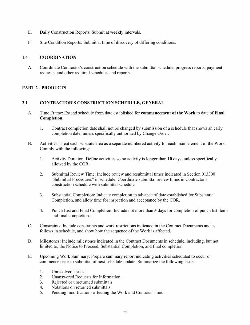
E. Daily Construction Reports: Submit at weekly intervals.
F. Site Condition Reports: Submit at time of discovery of differing conditions.
1.4 COORDINATION
A. Coordinate Contractor's construction schedule with the submittal schedule, progress reports, payment requests, and other required schedules and reports.
PART 2 - PRODUCTS
2.1 CONTRACTOR'S CONSTRUCTION SCHEDULE, GENERAL
A. Time Frame: Extend schedule from date established for commencement of the Work to date of Final Completion.
1. Contract completion date shall not be changed by submission of a schedule that shows an early completion date, unless specifically authorized by Change Order.
B. Activities: Treat each separate area as a separate numbered activity for each main element of the Work. Comply with the following:
1. Activity Duration: Define activities so no activity is longer than 10 days, unless specifically allowed by the COR.
2. Submittal Review Time: Include review and resubmittal times indicated in Section 013300 "Submittal Procedures" in schedule. Coordinate submittal review times in Contractor's construction schedule with submittal schedule.
3. Substantial Completion: Indicate completion in advance of date established for Substantial Completion, and allow time for inspection and acceptance by the COR.
4. Punch List and Final Completion: Include not more than 5 days for completion of punch list items
and final completion.
C. Constraints: Include constraints and work restrictions indicated in the Contract Documents and as follows in schedule, and show how the sequence of the Work is affected.
D. Milestones: Include milestones indicated in the Contract Documents in schedule, including, but not limited to, the Notice to Proceed, Substantial Completion, and final completion.
E. Upcoming Work Summary: Prepare summary report indicating activities scheduled to occur or commence prior to submittal of next schedule update. Summarize the following issues:
1. Unresolved issues. 2. Unanswered Requests for Information. 3. Rejected or unreturned submittals. 4. Notations on returned submittals. 5. Pending modifications affecting the Work and Contract Time.
21
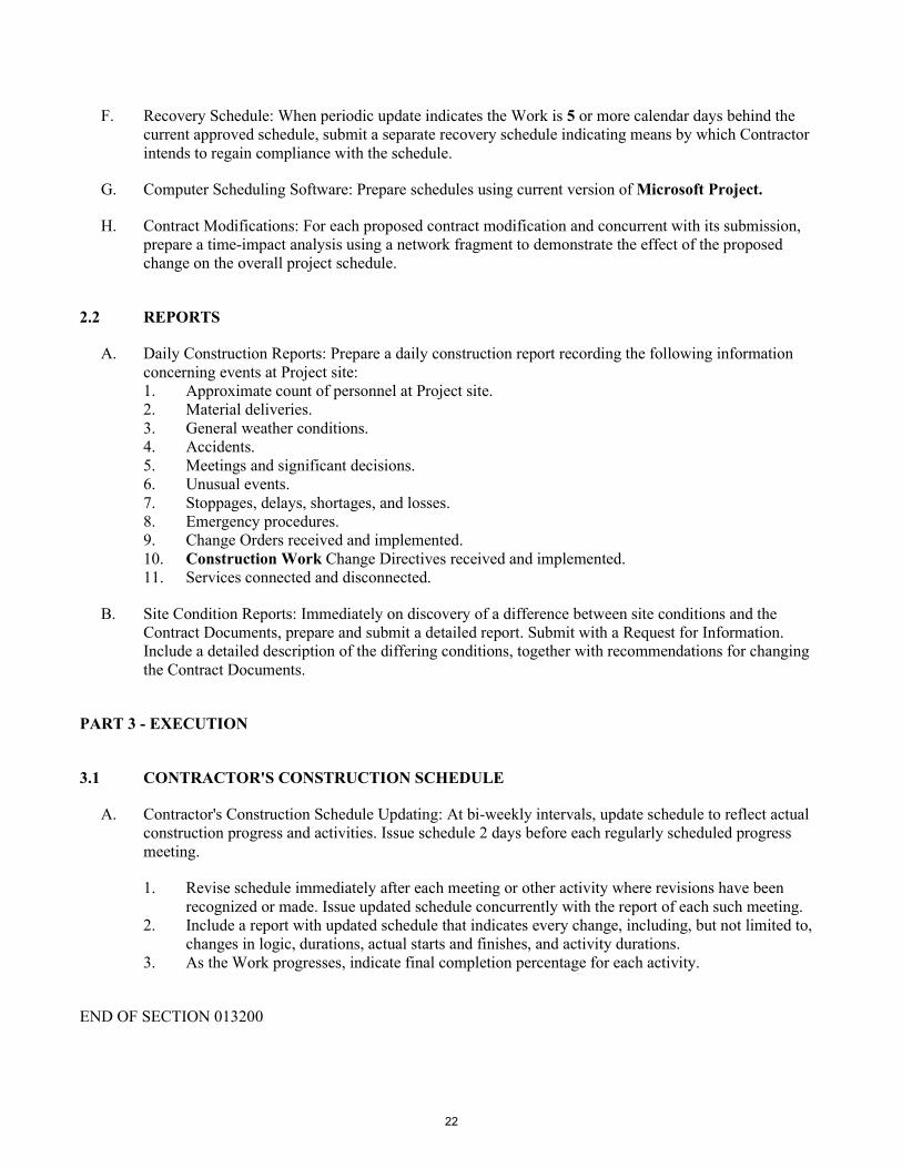
F. Recovery Schedule: When periodic update indicates the Work is 5 or more calendar days behind the current approved schedule, submit a separate recovery schedule indicating means by which Contractor intends to regain compliance with the schedule.
G. Computer Scheduling Software: Prepare schedules using current version of Microsoft Project.
H. Contract Modifications: For each proposed contract modification and concurrent with its submission, prepare a time-impact analysis using a network fragment to demonstrate the effect of the proposed change on the overall project schedule.
2.2 REPORTS
A. Daily Construction Reports: Prepare a daily construction report recording the following information concerning events at Project site: 1. Approximate count of personnel at Project site. 2. Material deliveries. 3. General weather conditions. 4. Accidents. 5. Meetings and significant decisions. 6. Unusual events. 7. Stoppages, delays, shortages, and losses. 8. Emergency procedures. 9. Change Orders received and implemented. 10. Construction Work Change Directives received and implemented. 11. Services connected and disconnected.
B. Site Condition Reports: Immediately on discovery of a difference between site conditions and the Contract Documents, prepare and submit a detailed report. Submit with a Request for Information. Include a detailed description of the differing conditions, together with recommendations for changing the Contract Documents.
PART 3 - EXECUTION
3.1 CONTRACTOR'S CONSTRUCTION SCHEDULE
A. Contractor's Construction Schedule Updating: At bi-weekly intervals, update schedule to reflect actual construction progress and activities. Issue schedule 2 days before each regularly scheduled progress meeting.
1. Revise schedule immediately after each meeting or other activity where revisions have been recognized or made. Issue updated schedule concurrently with the report of each such meeting.
2. Include a report with updated schedule that indicates every change, including, but not limited to, changes in logic, durations, actual starts and finishes, and activity durations.
3. As the Work progresses, indicate final completion percentage for each activity.
END OF SECTION 013200
22

SECTION 013300 - SUBMITTAL PROCEDURES
PART 1 - GENERAL
1.1 SUMMARY
A. Section includes requirements for the submittal schedule and administrative and procedural requirements for submitting Shop Drawings, Product Data, Samples, and other submittals.
B. Related Requirements:
1. Section 013200 "Construction Progress Documentation" for submitting schedules and reports, including Contractor's construction schedule.
1.2 DEFINITIONS
A. Action Submittals: Written and graphic information and physical samples that require COR’s responsive action.
B. Informational Submittals: Written and graphic information and physical samples that do not require COR’s responsive action. Submittals may be rejected for not complying with requirements.
1.3 ACTION SUBMITTALS
A. Submittal Schedule: Submit a schedule of submittals, arranged in chronological order by dates required by construction schedule. Include time required for review, ordering, manufacturing, fabrication, and delivery when establishing dates. Include additional time required for making corrections or revisions to submittals noted by COR’ and additional time for handling and reviewing submittals required by those corrections.
1.4 SUBMITTAL ADMINISTRATIVE REQUIREMENTS
A. Electronic copies of digital data files of the Contract Drawings may be provided for Contractor's use in preparing submittals.
B. Coordination: Coordinate preparation and processing of submittals with performance of construction activities.
C. Processing Time: Allow time for submittal review, including time for resubmittals, as follows. Time for review shall commence on COR’s receipt of submittal. No extension of the Contract Time will be authorized because of failure to transmit submittals enough in advance of the Work to permit processing, including resubmittals.
1. Initial Review: Allow 10 days for initial review of each submittal. Allow additional time if coordination with subsequent submittals is required. COR will advise Contractor when a submittal being processed must be delayed for coordination.
2. Resubmittal Review: Allow 10 days for review of each resubmittal.
23

D. Paper Submittals: Place a permanent label or title block on each submittal item for identification.
E. Electronic Submittals: Identify and incorporate information in each electronic submittal file as follows:
1. Assemble complete submittal package into a single indexed file incorporating submittal requirements of a single Specification Section and transmittal form with links enabling navigation to each item.
2. Name file with submittal number or other unique identifier, including revision identifier.
F. Options: Identify options requiring selection by COR.
G. Deviations: Identify deviations from the Contract Documents on submittals.
H. Resubmittals: Make resubmittals in same form and number of copies as initial submittal.
I. Use for Construction: Retain complete copies of submittals on Project site. Use only final action submittals that are marked with approval notation from COR’s action stamp.
PART 2 - PRODUCTS
2.1 SUBMITTAL PROCEDURES
A. General Submittal Procedure Requirements:
1. Submit electronic submittals via email as PDF electronic files.
a. COR will return annotated file. Annotate and retain one copy of file as an electronic Project record document file.
2. Action Submittals: Submit two paper copies of each submittal unless otherwise indicated. COR will return one copy.
3. Informational Submittals: Submit one paper copy of each submittal unless otherwise indicated. COR will not return copies.
4. Certificates and Certifications Submittals: Provide a statement that includes signature of entity responsible for preparing certification. Certificates and certifications shall be signed by an officer or other individual authorized to sign documents on behalf of that entity. a. Provide a notarized statement on original paper copy for the local permit.
B. Product Data: Collect information into a single submittal for each element of construction and type of product or equipment.
1. If information must be specially prepared for submittal because standard published data are not suitable for use, submit as Shop Drawings, not as Product Data.
2. Mark each copy of each submittal to show which products and options are applicable. 3. Include the following information, as applicable:
4. Submit Product Data before or concurrent with Samples.
C. Shop Drawings: Prepare Project-specific information, drawn accurately to scale. Do not base Shop Drawings on reproductions of the Contract Documents or standard printed data.
24

1. Preparation: Fully illustrate requirements in the Contract Documents. Include the following information, as applicable:
a. Identification of products. b. Schedules. c. Compliance with specified standards. d. Notation of coordination requirements. e. Notation of dimensions established by field measurement. f. Relationship and attachment to adjoining construction clearly indicated. g. Seal and signature of professional engineer if specified.
2. Submit Shop Drawings in the following format: a. Two opaque (bond) copies of each submittal. COR will return one copy.
D. Samples: Submit Samples for review of kind, color, pattern, and texture for a check of these characteristics with other elements and for a comparison of these characteristics between submittal and actual component as delivered and installed.
1. Transmit Samples that contain multiple, related components such as accessories together in one submittal package.
2. Identification: Attach label on unexposed side of Samples that includes the following:
a. Generic description of Sample. b. Product name and name of manufacturer. c. Sample source. d. Number and title of applicable Specification Section.
3. Disposition: Maintain sets of approved Samples at Project site, available for quality-control
comparisons throughout the course of construction activity. Sample sets may be used to determine final acceptance of construction associated with each set.
4. Samples for Initial Selection: Submit manufacturer's color charts consisting of units or sections of units showing the full range of colors, textures, and patterns available.
E. Contractor's Construction Schedule: Comply with requirements specified in Section 013200 "Construction Progress Documentation."
F. Test and Inspection Reports and Schedule of Tests and Inspections Submittals: Comply with requirements specified in Section 014000 "Quality Requirements."
G. Closeout Submittals and Maintenance Material Submittals: Comply with requirements specified in Section 017700 "Closeout Procedures."
H. Qualification Data: Prepare written information that demonstrates capabilities and experience of firm or person. Include lists of completed projects with project names and addresses, contact information of architects and owners, and other information specified.
I. Field Test Reports: Submit written reports indicating and interpreting results of field tests performed either during installation of product or after product is installed in its final location, for compliance with requirements in the Contract Documents.
25

PART 3 - EXECUTION
3.1 CONTRACTOR'S REVIEW
A. Action and Informational Submittals: Review each submittal and check for coordination with other Work of the Contract and for compliance with the Contract Documents. Note corrections and field dimensions. Mark with approval stamp before submitting to COR.
B. Project Closeout: See requirements in Section 017700 "Closeout Procedures."
3.2 COR’s ACTION
A. General: COR will not review submittals that do not bear Contractor's approval stamp and will return them without action.
B. Action Submittals: COR will review each submittal, make marks to indicate corrections or revisions required, and return it. COR will stamp each submittal with an action stamp.
C. Informational Submittals: COR will review each submittal and will not return it, or will return it if it does not comply with requirements..
D. Incomplete submittals are unacceptable, will be considered nonresponsive, and will be returned for resubmittal without review.
E. Submittals not required by the Contract Documents may not be reviewed and may be discarded.
F. The contractors shall submit, as part of their bid:
1. Qualification Data: For the contractor to demonstrate their capabilities and experience in similar projects in type and scale. Include lists of completed projects with project names and addresses, names and addresses of architects and owners, and other information specified.
2. Qualification data for the project manager and site engineer.
3. Special work procedures
4. Quality Control and Assurance program and plan
5. Safety Program and plan.
6. Technical data, manufacturer’s catalog.
7. List of all suppliers and sub-contractors
G. The contractor shall submit after contract award submittals as included in specification sections
END OF SECTION 013300
26
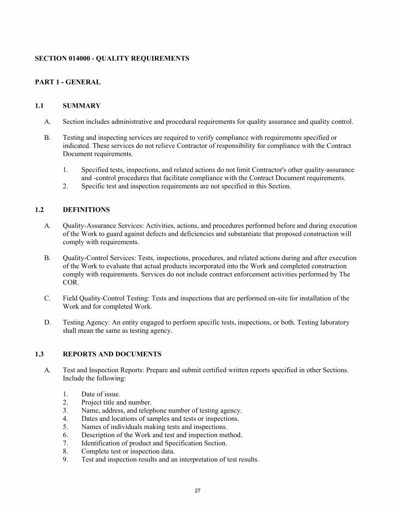
SECTION 014000 - QUALITY REQUIREMENTS
PART 1 - GENERAL
1.1 SUMMARY
A. Section includes administrative and procedural requirements for quality assurance and quality control.
B. Testing and inspecting services are required to verify compliance with requirements specified or indicated. These services do not relieve Contractor of responsibility for compliance with the Contract Document requirements.
1. Specified tests, inspections, and related actions do not limit Contractor's other quality-assurance and -control procedures that facilitate compliance with the Contract Document requirements.
2. Specific test and inspection requirements are not specified in this Section.
1.2 DEFINITIONS
A. Quality-Assurance Services: Activities, actions, and procedures performed before and during execution of the Work to guard against defects and deficiencies and substantiate that proposed construction will comply with requirements.
B. Quality-Control Services: Tests, inspections, procedures, and related actions during and after execution of the Work to evaluate that actual products incorporated into the Work and completed construction comply with requirements. Services do not include contract enforcement activities performed by The COR.
C. Field Quality-Control Testing: Tests and inspections that are performed on-site for installation of the Work and for completed Work.
D. Testing Agency: An entity engaged to perform specific tests, inspections, or both. Testing laboratory shall mean the same as testing agency.
1.3 REPORTS AND DOCUMENTS
A. Test and Inspection Reports: Prepare and submit certified written reports specified in other Sections. Include the following:
1. Date of issue. 2. Project title and number. 3. Name, address, and telephone number of testing agency. 4. Dates and locations of samples and tests or inspections. 5. Names of individuals making tests and inspections. 6. Description of the Work and test and inspection method. 7. Identification of product and Specification Section. 8. Complete test or inspection data. 9. Test and inspection results and an interpretation of test results.
27

10. Record of temperature and weather conditions at time of sample taking and testing and inspecting.
11. Name and signature of laboratory inspector. 12. Recommendations on retesting and re-inspecting.
B. Permits, Licenses, and Certificates: For Owner's records, submit copies of permits, licenses, certifications, inspection reports, releases, jurisdictional settlements, notices, receipts for fee payments, judgments, correspondence, records, and similar documents, established for compliance with standards and regulations bearing on performance of the Work.
1.4 QUALITY ASSURANCE
A. General: Qualifications paragraphs in this article establish the minimum qualification levels required; individual Specification Sections specify additional requirements.
B. Manufacturer Qualifications: A firm experienced in manufacturing products or systems similar to those indicated for this Project and with a record of successful in-service performance, as well as sufficient production capacity to produce required units.
C. Fabricator Qualifications: A firm experienced in producing products similar to those indicated for this Project and with a record of successful in-service performance, as well as sufficient production capacity to produce required units.
D. Installer Qualifications: A firm or individual experienced in installing, erecting, or assembling work similar in material, design, and extent to that indicated for this Project, whose work has resulted in construction with a record of successful in-service performance.
E. Testing Agency Qualifications: an independent agency with the experience and capability to conduct testing and inspecting indicated.
F. Manufacturer's Representative Qualifications: An authorized representative of manufacturer who is trained and approved by manufacturer to observe and inspect installation of manufacturer's products that are similar in material, design, and extent to those indicated for this Project.
1.5 QUALITY CONTROL
A. Contractor Responsibilities: Tests and inspections not explicitly assigned to Owner are Contractor's responsibility. Perform additional quality-control activities required to verify that the Work complies with requirements, whether specified or not.
1. Where services are indicated as Contractor's responsibility, engage a qualified testing agency to perform these quality-control services.
2. Where quality-control services are indicated as Contractor's responsibility, submit a certified written report, in duplicate, of each quality-control service.
3. Testing and inspecting requested by Contractor and not required by the Contract Documents are Contractor's responsibility.
28

B. Retesting/Re-inspecting: Regardless of whether original tests or inspections were Contractor's responsibility, provide quality-control services, including retesting and reinspecting, for construction that replaced Work that failed to comply with the Contract Documents.
C. Testing Agency Responsibilities: Cooperate with COR in performance of duties. Provide qualified personnel to perform required tests and inspections. 1. Facilities for storage and field curing of test samples.
D. Coordination: Coordinate sequence of activities to accommodate required quality-assurance and -control services with a minimum of delay and to avoid necessity of removing and replacing construction to accommodate testing and inspecting.
PART 2 - PRODUCTS (Not Used)
PART 3 - EXECUTION
3.1 REPAIR AND PROTECTION
A. General: On completion of testing, inspecting, sample taking, and similar services, repair damaged construction and restore substrates and finishes.
1. Provide materials and comply with installation requirements specified in other Specification Sections or matching existing substrates and finishes. Restore patched areas and extend restoration into adjoining areas with durable seams that are as invisible as possible. Comply with the Contract Document requirements for cutting and patching in Section 017300 "Execution."
B. Protect construction exposed by or for quality-control service activities.
C. Repair and protection are Contractor's responsibility, regardless of the assignment of responsibility for quality-control services.
END OF SECTION 014000
29

SECTION 015000 - TEMPORARY FACILITIES AND CONTROLS
PART 1 - GENERAL
1.1 SUMMARY
A. Section includes requirements for temporary utilities, support facilities, and security and protection
facilities.
B. Related Requirements:
1. Section 011000 "Summary" for work restrictions and limitations on utility interruptions.
1.2 USE CHARGES
A. Water and Sewer Service from Existing System: Water from existing water system is available for use
without metering and without payment of use charges. Provide connections and extensions of services
as required for construction operations.
B. Electric Power Service from Existing System: Electric power from existing system is available for use
without metering and without payment of use charges. Provide connections and extensions of services
as required for construction operations.
1.3 QUALITY ASSURANCE
A. Electric Service: Comply with NECA, NEMA, and UL standards and regulations for temporary electric
service. Install service to comply with NFPA 70.
PART 2 - PRODUCTS
2.1 MATERIALS
A. Wood Enclosure Fence, corrugated sheets or portable chain link fence around construction area.
2.2 TEMPORARY FACILITIES
A. Storage and Fabrication Sheds: Provide sheds sized, furnished, and equipped to accommodate materials
and equipment for construction operations if required.
30

PART 3 - EXECUTION
3.1 TEMPORARY UTILITY INSTALLATION
A. General: Install temporary service or connect to existing service.
B. Water Service: Connect to existing water service facilities. Clean and maintain water service facilities in
a condition acceptable to Owner. At Substantial Completion, restore these facilities to condition existing
before initial use.
C. Electric Power Service: Connect to existing electric power service. Maintain equipment in a condition
acceptable to Occupant.
D. Lighting: Provide temporary lighting with local switching that provides adequate illumination for
construction operations, observations, inspections, and traffic conditions.
E. Telephone Service: Provide superintendent with cellular telephone.
3.2 SUPPORT FACILITIES INSTALLATION
A. Project Signs: Provide Project signs as indicated. Unauthorized signs are not permitted.
1. Identification Signs: Provide Project identification signs.
2. Temporary Signs: Provide other signs as indicated and as required to inform public and
individuals seeking entrance to Project. Provide temporary, directional signs for construction
personnel and visitors.
3.3 SECURITY AND PROTECTION FACILITIES INSTALLATION
A. Protection of Existing Facilities: Protect existing vegetation, equipment, structures, utilities, and other
improvements at Project site and on adjacent properties, except those indicated to be removed or altered.
Repair damage to existing facilities.
B. Environmental Protection: Provide protection, operate temporary facilities, and conduct construction as
required to comply with environmental regulations and that minimize possible air, waterway, and
subsoil contamination or pollution or other undesirable effects.
C. Tree and Plant Protection: Comply with requirements of the COR on the protection of trees and plants.
D. Temporary Fire Protection: Install and maintain temporary fire-protection facilities of types needed to
protect against reasonably predictable and controllable fire losses. Comply with NFPA 241; manage fire
prevention program.
1. Prohibit smoking in construction areas.
2. Supervise welding operations.
3. Develop and supervise an overall fire-prevention and -protection program for personnel at Project
site. Post warnings and information.
31
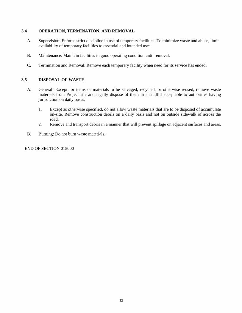
3.4 OPERATION, TERMINATION, AND REMOVAL
A. Supervision: Enforce strict discipline in use of temporary facilities. To minimize waste and abuse, limit
availability of temporary facilities to essential and intended uses.
B. Maintenance: Maintain facilities in good operating condition until removal.
C. Termination and Removal: Remove each temporary facility when need for its service has ended.
3.5 DISPOSAL OF WASTE
A. General: Except for items or materials to be salvaged, recycled, or otherwise reused, remove waste
materials from Project site and legally dispose of them in a landfill acceptable to authorities having
jurisdiction on daily bases.
1. Except as otherwise specified, do not allow waste materials that are to be disposed of accumulate
on-site. Remove construction debris on a daily basis and not on outside sidewalk of across the
road.
2. Remove and transport debris in a manner that will prevent spillage on adjacent surfaces and areas.
B. Burning: Do not burn waste materials.
END OF SECTION 015000
32

SECTION 015000 - TEMPORARY FACILITIES AND CONTROLS
PART 1 - GENERAL
1.1 SUMMARY
A. Section includes requirements for temporary utilities, support facilities, and security and protection facilities.
B. Related Requirements:
1. Section 011000 "Summary" for work restrictions and limitations on utility interruptions.
1.2 USE CHARGES
A. Water and Sewer Service from Existing System: Water from existing water system is available for use without metering and without payment of use charges. Provide connections and extensions of services as required for construction operations.
B. Electric Power Service from Existing System: Electric power from existing system is available for use without metering and without payment of use charges. Provide connections and extensions of services as required for construction operations.
1.3 QUALITY ASSURANCE
A. Electric Service: Comply with NECA, NEMA, and UL standards and regulations for temporary electric service. Install service to comply with NFPA 70.
PART 2 - PRODUCTS
2.1 MATERIALS
A. Wood Enclosure Fence, corrugated sheets or portable chain link fence around construction area.
2.2 TEMPORARY FACILITIES
A. Storage and Fabrication Sheds: Provide sheds sized, furnished, and equipped to accommodate materials and equipment for construction operations if required.
33

PART 3 - EXECUTION
3.1 TEMPORARY UTILITY INSTALLATION
A. General: Install temporary service or connect to existing service.
B. Water Service: Connect to existing water service facilities. Clean and maintain water service facilities in a condition acceptable to Owner. At Substantial Completion, restore these facilities to condition existing before initial use.
C. Electric Power Service: Connect to existing electric power service. Maintain equipment in a condition acceptable to Occupant.
D. Lighting: Provide temporary lighting with local switching that provides adequate illumination for construction operations, observations, inspections, and traffic conditions.
E. Telephone Service: Provide superintendent with cellular telephone.
3.2 SUPPORT FACILITIES INSTALLATION
A. Project Signs: Provide Project signs as indicated. Unauthorized signs are not permitted.
1. Identification Signs: Provide Project identification signs.
2. Temporary Signs: Provide other signs as indicated and as required to inform public and individuals seeking entrance to Project. Provide temporary, directional signs for construction personnel and visitors.
3.3 SECURITY AND PROTECTION FACILITIES INSTALLATION
A. Protection of Existing Facilities: Protect existing vegetation, equipment, structures, utilities, and other improvements at Project site and on adjacent properties, except those indicated to be removed or altered. Repair damage to existing facilities.
B. Environmental Protection: Provide protection, operate temporary facilities, and conduct construction as required to comply with environmental regulations and that minimize possible air, waterway, and subsoil contamination or pollution or other undesirable effects.
C. Tree and Plant Protection: Comply with requirements of the COR on the protection of trees and plants.
D. Temporary Fire Protection: Install and maintain temporary fire-protection facilities of types needed to protect against reasonably predictable and controllable fire losses. Comply with NFPA 241; manage fire prevention program.
1. Prohibit smoking in construction areas. 2. Supervise welding operations. 3. Develop and supervise an overall fire-prevention and -protection program for personnel at Project
site. Post warnings and information.
34

3.4 OPERATION, TERMINATION, AND REMOVAL
A. Supervision: Enforce strict discipline in use of temporary facilities. To minimize waste and abuse, limit availability of temporary facilities to essential and intended uses.
B. Maintenance: Maintain facilities in good operating condition until removal.
C. Termination and Removal: Remove each temporary facility when need for its service has ended.
3.5 DISPOSAL OF WASTE
A. General: Except for items or materials to be salvaged, recycled, or otherwise reused, remove waste materials from Project site and legally dispose of them in a landfill acceptable to authorities having jurisdiction on daily bases.
1. Except as otherwise specified, do not allow waste materials that are to be disposed of accumulate on-site. Remove construction debris on a daily basis and not on outside sidewalk of across the road.
2. Remove and transport debris in a manner that will prevent spillage on adjacent surfaces and areas.
B. Burning: Do not burn waste materials.
END OF SECTION 015000
35

SECTION 017300 - EXECUTION
PART 1 - GENERAL
1.1 SUMMARY
A. Section includes general administrative and procedural requirements governing execution of the Work including, but not limited to, the following:
1. Construction layout. 2. Installation of the Work. 3. Cutting and patching. 4. Progress cleaning. 5. Starting and adjusting.
B. Related Requirements:
1. Section 011000 "Summary" for limits on use of Project site. 2. Section 017700 "Closeout Procedures" for submitting final property survey with Project Record
Documents, recording of Owner-accepted deviations from indicated lines and levels, and final cleaning.
1.2 QUALITY ASSURANCE
A. Cutting and Patching: Comply with requirements for and limitations on cutting and patching of construction elements.
1. Do not cut and patch construction elements or components in a manner that could change their load-carrying capacity, that results in reducing their capacity to perform as intended, or that results in increased maintenance or decreased operational life or safety.
PART 2 - PRODUCTS
2.1 MATERIALS
A. General: Comply with requirements specified in other Sections.
B. In-Place Materials: Use materials for patching identical to in-place materials. For exposed surfaces, use materials that visually match in-place adjacent surfaces to the fullest extent possible.
36

PART 3 - EXECUTION
3.1 EXAMINATION
A. Existing Conditions: Before beginning site-work, investigate and verify the existence and location of underground utilities, mechanical and electrical systems, and other construction affecting the Work.
B. Acceptance of Conditions: Examine substrates, areas, and conditions, with Installer or Applicator present where indicated, for compliance with requirements for installation tolerances and other conditions affecting performance. Record observations.
1. Verify compatibility with and suitability of substrates, including compatibility with existing finishes or primers.
2. Examine walls, floors, and roofs for suitable conditions where products and systems are to be installed.
3. Proceed with installation only after unsatisfactory conditions have been corrected. Proceeding with the Work indicates acceptance of surfaces and conditions.
4. The submission of the bid will be a conclusive evidence that the bidder has complied with all conditions related to the character, quality and quantity of work requirements to be performed. No claims for additional time or compensation due to variations between existing and conditions encountered during construction will be honored. Failure of the contractor to thoroughly inspect and identify defects, if any, shall not release him from the responsibility to guarantee the whole works (Existing to remain, and new works) for the period specified in the contract terms.
C. Proceed with installation only after unsatisfactory conditions have been corrected. Proceeding with the Work indicates acceptance of surfaces and conditions.
3.2 SPECIAL WORK PROCEDURES
A. Working Hours: All work shall be performed during hours from 8:00 a.m. to 6:00 p.m., Sunday through Thursday except for the holidays identified in the holiday schedule attached, which are considered non-working days. Working after hours and weekends may be required and approved by the COR with at least 24 hours advance notice, especially in demolition work, for shut down of utilities, or when the work obstruct the regular function of the building.
B. Scaffolding, shores, material hoist and trash disposal shall be the responsibility of the contractor.
C. Security Procedures: All contractors’ personnel shall be subject to all the security procedures required for clearance of personnel working inside U.S. Embassy Compounds. These requirements shall include:
1. Submission of valid finger prints, addressed to the U.S. Embassy and copy of the Egyptian ID, two week prior to the required date to access the site.
2. Access for trucks shall be granted on a 48 hours (two working days) advance notice show-ing: 1) Drivers name, 2) Copy of driver’s ID, 3) Truck description and plate number, and 4) date and time access required.
37

3. Access for daily laborers can be given for three days, with a 48 hours advance notice showing the name of the persons, ID #, date and place of issue, and a copy of the ID. Access will be given for one time only (three days) for day laborers.
4. All contractor personnel shall be subject to a daily check (in and out) by the US government guard personnel.
5. Failure of the contractor to fulfill any security requirement in a timely manner shall not be con-structed as a base for any time and money extension.
6. Delay or suspension of work due to the U.S. government security regulations or requirements shall not be a base for claims
3.3 PREPARATION
A. Existing Utility Information: Furnish information to the COR that is necessary to adjust, move, or relocate existing utility lines, services, or other utility appurtenances located in or affected by construction.
B. Field Measurements: Take field measurements as required to fit the Work properly. Recheck measurements before installing each product. Where portions of the Work are indicated to fit to other construction, verify dimensions of other construction by field measurements before fabrication. Coordinate fabrication schedule with construction progress to avoid delaying the Work.
C. Space Requirements: Verify space requirements and dimensions of items shown diagrammatically on Drawings.
D. Review of Contract Documents and Field Conditions: Immediately on discovery of the need for clarification of the Contract Documents caused by differing field conditions outside the control of Contractor, submit a request for information to Architect according to requirements in Section 013100 "Project Management and Coordination."
3.4 CONSTRUCTION LAYOUT
A. Verification: Before proceeding to lay out the Work, verify layout information shown on Drawings, in relation to the property survey. If discrepancies are discovered, notify the COR promptly.
B. Site Improvements: Locate and lay out site improvements, including pavements, grading, fill and topsoil placement, utility slopes, and rim and invert elevations.
C. Building Lines and Levels: Locate and lay out control lines and levels for column grids, and floor levels, including those required for mechanical and electrical work. Transfer survey markings and elevations for use with control lines and levels. Level foundations from two or more locations.
3.5 INSTALLATION
A. General: Locate the Work and components of the Work accurately, in correct alignment and elevation, as indicated.
1. Make vertical work plumb and make horizontal work level.
38

2. Where space is limited, install components to maximize space available for maintenance and ease of removal for replacement.
3. Conceal pipes, ducts, and wiring in finished areas unless otherwise indicated.
B. Comply with manufacturer's written instructions and recommendations for installing products in applications indicated.
C. Install products at the time and under conditions that will ensure the best possible results. Maintain conditions required for product performance until Substantial Completion.
D. Conduct construction operations so no part of the Work is subjected to damaging operations or loading in excess of that expected during normal conditions of occupancy.
E. Sequence the Work and allow adequate clearances to accommodate movement of construction items on site and placement in permanent locations.
F. Tools and Equipment: Do not use tools or equipment that produce harmful noise levels.
G. Templates: Obtain and distribute to the parties involved templates for work specified to be factory prepared and field installed. Check Shop Drawings of other work to confirm that adequate provisions are made for locating and installing products to comply with indicated requirements.
H. Attachment: Provide blocking and attachment plates and anchors and fasteners of adequate size and number to securely anchor each component in place, accurately located and aligned with other portions of the Work. Where size and type of attachments are not indicated, verify size and type required for load conditions.
I. Joints: Make joints of uniform width. Where joint locations in exposed work are not indicated, arrange joints for the best visual effect. Fit exposed connections together to form hairline joints.
J. Hazardous Materials: Use products, cleaners, and installation materials that are not considered hazardous.
3.6 CUTTING AND PATCHING
A. Cutting and Patching, General: Employ skilled workers to perform cutting and patching. Proceed with cutting and patching at the earliest feasible time, and complete without delay.
1. Cut in-place construction to provide for installation of other components or performance of other construction, and subsequently patch as required to restore surfaces to their original condition.
B. Temporary Support: Provide temporary support of work to be cut.
C. Protection: Protect in-place construction during cutting and patching to prevent damage. Provide protection from adverse weather conditions for portions of Project that might be exposed during cutting and patching operations.
D. Adjacent Occupied Areas: Avoid interference with use of adjoining areas or interruption of free passage to adjoining areas.
39

E. Cutting: Cut in-place construction by sawing, drilling, breaking, chipping, grinding, and similar operations, including excavation, using methods least likely to damage elements retained or adjoining construction.
F. Patching: Patch construction by filling, repairing, refinishing, closing up, and similar operations following performance of other work. Patch with durable seams that are as invisible as practicable. Provide materials and comply with installation requirements specified in other Sections, where applicable.
G. Cleaning: Clean areas and spaces where cutting and patching are performed. Remove paint, mortar, oils, putty, and similar materials from adjacent finished surfaces.
3.7 PROGRESS CLEANING
A. General: Clean Project site and work areas daily, including common areas. Enforce requirements strictly. Dispose of materials lawfully.
1. Comply with requirements in NFPA 241 for removal of combustible waste materials and debris. 2. Do not hold waste materials more than two days.
B. Site: Maintain Project site free of waste materials and debris.
C. Work Areas: Clean areas where work is in progress to the level of cleanliness necessary for proper execution of the Work.
1. Remove liquid spills promptly. 2. Where dust would impair proper execution of the Work, broom-clean or vacuum the entire work
area, as appropriate.
D. Installed Work: Keep installed work clean. Clean installed surfaces using only cleaning materials that are not hazardous to health or property and that will not damage exposed surfaces.
E. Waste Disposal: Do not bury or burn waste materials on-site. Do not wash waste materials down sewers or into waterways.
3.8 SECURITY AND SITE ACCESS PROCEDURES
D. All contractors’ personnel shall be subject to all the security procedures required for clearance of personnel working inside U.S. Embassy Compounds. These requirements shall include:
1. Submission of valid finger prints, addressed to the U.S. Embassy and copy of the Egyptian ID, two week prior to the required date to access the site.
7. Access for trucks shall be granted on a 48 hours (two working days) advance notice show-ing: 1) Drivers name, 2) Copy of driver’s ID, 3) Truck description and plate number, and 4) date and time access required.
8. Access for daily laborers can be given for three days, with a 48 hours advance notice showing the name of the persons, ID #, date and place of issue, and a copy of the ID. Access will be given for one time only (three days) for day laborers.
40

9. All contractor personnel shall be subject to a daily check (in and out) by the US government guard personnel.
10. Failure of the contractor to fulfill any security requirement in a timely manner shall not be con-structed as a base for any time and money extension.
11. Delay or suspension of work due to the U.S. government security regulations or requirements shall not be a base for claims
3.9 SAFETY
A. The contractor must comply to the following: 1. DOSAR Accident Prevention Clause 652-236-70, included below in full text. 2. SAFETY AND HEALTH REQUIREMENTS of the US Army Corps of Engineers - EM 385-1-1.
http://www.usace.army.mil/SafetyandOccupationalHealth/SafetyandHealthRequirementsManual.aspx
3. Safety requirements that is specific to the job and will be addressed and documented during the pre-construction meeting.
41

3.10 ACCIDENT PREVENTION CLAUSE (APR 2004) (IN FULL TEST)
(a) General. The contractor shall provide and maintain work environments and procedures which will safeguard the public and Government personnel, property, materials, supplies, and equipment exposed to contractor operations and activities; avoid interruptions of Government operations and delays in project completion dates; and, control costs in the performance of this contract. For these purposes, the contractor shall:
(1) Provide appropriate safety barricades, signs and signal lights; (2) Comply with the standards issued by any local government authority having jurisdiction over occupational
health and safety issues; and, (3) Ensure that any additional measures the contracting officer determines to be reasonably necessary for this
purpose are taken. (4) For overseas construction projects, the contracting officer shall specify in writing additional requirements
regarding safety if the work involves: (i) Scaffolding; (ii) Work at heights above two (2) meters; (iii) Trenching or other excavation greater than one (1) meter in depth; (iv) Earth moving equipment; (v) Temporary wiring, use of portable electric tools, or other recognized electrical hazards.
Temporary wiring and portable electric tools require the use of a ground fault circuit interrupter (GFCI) in the affected circuits; other electrical hazards may also require the use of a GFCI;
(vi) Work in confined spaces (limited exits, potential for oxygen less that 19.5 percent or combustible atmosphere, potential for solid or liquid engulfment, or other hazards considered to be immediately dangerous to life or health such as water tanks, transformer vaults, sewers, cisterns, etc.);
(vii) Hazardous materials - a material with a physical or health hazard including but not limited to, flammable, explosive, corrosive, toxic, reactive or unstable, or any operations which creates any kind of contamination inside an occupied building such as dust from demolition activities, paints, solvents, etc.; or
(viii) Hazardous noise levels.
(b) Records. The contractor shall maintain an accurate record of exposure data on all accidents incident to work performed under this contract resulting in death, traumatic injury, occupational disease, or damage to or theft of property, materials, supplies, or equipment. The contractor shall report this data in the manner prescribed by the contracting officer.
(c) Subcontracts. The contractor shall be responsible for its subcontractor’s compliance with this clause.
(d) Written program. Before commencing work, the contractor shall: (1) Submit a written plan to the contracting officer for implementing this clause. The plan shall include
specific management or technical procedures for effectively controlling hazards associated with the project; and,
(2) Meet with the contracting officer to discuss and develop a mutual understanding relative to administration of the overall safety program.
(e) Notification. The contracting officer shall notify the contractor of any non-compliance with these requirements and the corrective actions required. This notice, when delivered to the contractor or the contractor’s representative
42

on site, shall be deemed sufficient notice of the non-compliance and corrective action required. After receiving the notice, the contractor shall immediately take corrective action. If the contractor fails or refuses to promptly take corrective action, the contracting officer may issue an order suspending all or part of the work until satisfactory corrective action has been taken. The contractor shall not be entitled to any equitable adjustment of the contract price or extension of the performance schedule on any suspension of work order issued under this clause.
(End of clause)
3.11 PROTECTION OF INSTALLED CONSTRUCTION
A. Provide final protection and maintain conditions that ensure installed Work is without damage or deterioration at time of Substantial Completion.
3.12 CORRECTION OF THE WORK
A. Repair or remove and replace defective construction. Restore damaged substrates and finishes. Comply with requirements in Division 1 Section "Cutting and Patching."
1. Repairing includes replacing defective parts, refinishing damaged surfaces, touching up with matching materials, and properly adjusting operating equipment.
B. Restore permanent facilities used during construction to their specified condition.
C. Remove and replace damaged surfaces that are exposed to view if surfaces cannot be repaired without visible evidence of repair.
D. Remove and replace chipped, scratched, and broken glass or reflective surfaces.
END OF SECTION 017300
43

SECTION 017700 - CLOSEOUT PROCEDURES
PART 1 - GENERAL
1.1 SUMMARY
A. Section includes administrative and procedural requirements for contract closeout, including, but not limited to, the following:
1. Substantial Completion procedures. 2. Final completion procedures. 3. Warranties. 4. Final cleaning. 5. Repair of the Work.
B. Related Requirements:
1.2 SUBSTANTIAL COMPLETION PROCEDURES
A. Contractor's List of Incomplete Items: Prepare and submit a list of items to be completed and corrected (Contractor's punch list), indicating the value of each item on the list and reasons why the Work is incomplete.
B. Inspection: Submit a written request for inspection to determine Substantial Completion a minimum of 5 days prior to date the work will be completed and ready for final inspection.
1. Re-inspection: Request re-inspection when the Work identified in previous inspections as incomplete is completed or corrected.
2. Results of completed inspection will form the basis of requirements for final completion.
1.3 FINAL COMPLETION PROCEDURES
A. Inspection: Submit a written request for final inspection to determine acceptance. On receipt of request, COR will either proceed with inspection or notify Contractor of unfulfilled requirements.
1. Re-inspection: Request re-inspection when the Work identified in previous inspections as incomplete is completed or corrected.
1.4 LIST OF INCOMPLETE ITEMS (PUNCH LIST)
A. Include name and identification of each space and area affected by construction operations for incomplete items and items needing correction including, if necessary, areas disturbed by Contractor that are outside the limits of construction.
44

PART 2 - PRODUCTS
2.1 MATERIALS
A. Cleaning Agents: Use cleaning materials and agents recommended by manufacturer or fabricator of the surface to be cleaned.
PART 3 - EXECUTION
3.1 FINAL CLEANING
A. General: Perform final cleaning. Conduct cleaning and waste-removal operations to comply with local laws and ordinances and Federal and local environmental and antipollution regulations.
3.2 REPAIR OF THE WORK
A. Complete repair and restoration operations before requesting inspection for determination of Substantial Completion.
B. Repair or remove and replace defective construction. Repairing includes replacing defective parts, refinishing damaged surfaces, touching up with matching materials, and properly adjusting operating equipment. Where damaged or worn items cannot be repaired or restored, provide replacements. Remove and replace operating components that cannot be repaired. Restore damaged construction and permanent facilities used during construction to specified condition.
1. Remove and replace chipped, scratched, and broken glass, reflective surfaces, and other damaged transparent materials.
2. Touch up and otherwise repair and restore marred or exposed finishes and surfaces. Replace finishes and surfaces that that already show evidence of repair or restoration.
END OF SECTION 017700
45
SECTION 024119 - SELECTIVE DEMOLITION
PART 1 - GENERAL
1.1 SUMMARY
A. Section Includes:
1. Demolition and removal of selected portions of building or structure. 2. Demolition and removal of selected site elements.
1.2 MATERIALS OWNERSHIP
A. Unless otherwise indicated, demolition waste becomes property of Contractor.
1.3 FIELD CONDITIONS
A. Notify COR of discrepancies between existing conditions and Drawings before proceeding with selective demolition.
B. Storage or sale of removed items or materials on-site is not permitted.
C. Utility Service: Maintain existing utilities indicated to remain in service and protect them against damage during selective demolition operations.
PART 2 - PRODUCTS
2.1 PERFORMANCE REQUIREMENTS
A. Regulatory Requirements: Comply with governing EPA notification regulations before beginning selective demolition. Comply with hauling and disposal regulations of authorities having jurisdiction.
PART 3 - EXECUTION
3.1 EXAMINATION
A. Verify that utilities have been disconnected and capped before starting selective demolition operations.
3.2 UTILITY SERVICES AND MECHANICAL/ELECTRICAL SYSTEMS
A. Existing Services/Systems to Remain: Maintain services/systems indicated to remain and protect them against damage.
46

B. Existing Services/Systems to Be Removed, Relocated, or Abandoned: Locate, identify, disconnect, and seal or cap off utility services and mechanical/electrical systems serving areas to be selectively demolished.
3.3 PROTECTION
A. Temporary Protection: Provide temporary barricades and other protection required to prevent injury to people and damage to adjacent buildings and facilities to remain.
B. Temporary Shoring: Design, provide, and maintain shoring, bracing, and structural supports as required to preserve stability and prevent movement, settlement, or collapse of construction and finishes to remain, and to prevent unexpected or uncontrolled movement or collapse of construction being demolished.
C. Remove temporary barricades and protections where hazards no longer exist.
3.4 SELECTIVE DEMOLITION
A. General: Demolish and remove existing construction only to the extent required by new construction and as indicated. Use methods required to complete the Work within limitations of governing regulations and as follows:
B. Site Access and Temporary Controls: Conduct selective demolition and debris-removal operations to ensure minimum interference with roads, streets, walks, walkways, and other adjacent occupied and used facilities.
3.5 CLEANING
A. Remove demolition waste materials from Project site [and dispose of them in an approved construction and demolition waste landfill acceptable to authorities having jurisdiction.]
1. Do not allow demolished materials to accumulate on-site. 2. Remove and transport debris in a manner that will prevent spillage on adjacent surfaces and areas.
B. Clean adjacent structures and improvements of dust, dirt, and debris caused by selective demolition operations. Return adjacent areas to condition existing before selective demolition operations began.
END OF SECTION 024119
47

SECTION 042200 - UNIT MASONRY ASSEMBLIES PART 1 - GENERAL
1.1 SECTION INCLUDES
A. Hollow Concrete Blocks. B. Mortar and Grout.
1.2 RELATED SECTIONS
A. Section 092400 – Cement Plastering
1.3 SUBMITTALS
A. Submit Manufacturer’s product data for each type including design mix and admixture limitations. B. Samples: Submit two samples of each type and size of block units, obtain approval before placing
orders with suppliers.
1.4 QUALITY ASSURANCE
A. Perform Work in accordance with ES 1292. B. Testing: independent testing laboratory in accordance with ES 1292 & ES 1349.
1.5 DELIVERY, STORAGE, AND HANDLING
A. Deliver, store, protect, and handle products to site. B. Maintain packaged materials clean, dry, and protected against dampness, and foreign matter. C. Storing: stack blocks so that they are stable and clear of the ground. Protect from inclement weather
and keep dry. D. Cement: deliver in sealed bags bearing the manufacturer’s name and store in piles not more than ten
bags high in perfectly dry weatherproof sheds clear from ground on planks or other damp-proofing supports.
E. Sand: aggregates shall be stored in separate stockpiles and to be free from all foreign materials
which may become mixed with them.
PART 2 - PRODUCTS
2.1 MANUFACTURERS
A. Available Manufacturers: Subject to compliance with requirements, manufacturers offering accessories that may be incorporated into the Work include, but are not limited to, the following:
48

1. Tooblat
Cairo Alexandria Desert Road, Kilo 26 Tel: 5390719 – 20 – 21 –22 – 23 –24 Fax: 5390725
2. Arab Brick
3 Ahmed Oraby Street, Mohandessin Tel: 5010926 - 25
3. Misr Brick 15 May City, Helwan Tel: 5500812 – 5501385 Fax: 5506528
2.2 BLOCKS
A. Mortar and grout: Mortar aggregate, natural color ES 1108. B. Concrete Blocks, unless otherwise specified, are to be to ES 1292, manufactured from ordinary
Portland cement to ES 373 and natural aggregates to ES 1109.
1. Hollow Concrete Blocks shall be: - Density: 1500 kg/m3
- Total volume of holes shall not exceed 50% of the unit volume - Shell and membrane thickness of the solid portion shall not be less than
20mm
C. Testing Hollow Concrete Blocks: ten blocks from each batch are to be selected by the COR for testing for compressive strength. Results are to be as follows:
- Individual block: not less than 25 kg/cm2 of gross area
- Average of 10 blocks: not less than 30 kg/cm2 of gross area. 2.3 MORTAR AND GROUT MATERIALS
A. Ingredients for mortar shall be measured in proper clean gauge boxes.
B. Cement: Ordinary Portland cement to ES 373. Do not use cementitious materials that have become damp.
C. Aggregates: Comply to ES 1108. Except for the joints less than 6mm, use aggregates graded with
100% passing sieve no. 16. D. Water: Clean and potable.
2.4 ACCESSORIES
A. Joint reinforcing: Welded wire with deformed side rods
49

1. Steel Wire: 9 gauge (4.8 mm) galvanized steel. 2. Type: Ladder or truss type.
B. Ties and Anchors:
1. Bent Wire Ties: Galvanized Steel 2. Rigid Anchors: Galvanized steel straps. 3. Masonry to concrete frame: Two pieces galvanized steel anchor. 4. Unit type masonry inserts in concrete: Malleable iron. 5. Anchor Bolts: ASTM A307, grade A, galvanized.
C. Masonry Accessories:
1. Non metallic expansion joint strips. 2. Preformed control joint gaskets. 3. Bond breaker strips.
2.5 MORTAR
A. Mortar: shall be cement-sand mortar.
1. Consisting of 350 kgs Portland Cement, 1m3 sand and a minimum amount of water to produce a workable consistency.
2. Mixed mortar components dry and then add water until the correct consistency is obtained.
3. Use mortar within 1 hour of the addition of water.
4. Limit cemintitious materials in mortar to Portland cement and lime.
B. Grout: shall be fine grout of 1 part ordinary Portland cement to 2 or 3 parts of fine aggregates by volume. Fine aggregate to be measured in damp loose condition.
PART 3 - EXECUTION
3.1 GENERAL
A. Comply with referenced unit masonry Egyptian standard and other requirements. B. Construct walls with all materials fully bonded or tied together to ensure compliance with design
requirements for stability, strength, fire resistance, thermal and sound insulation as relevant.
50

3.2 LAYING
A. Concrete Blocks: do not use non-autoclaved concrete blocks until four weeks after casting. Do not wet concrete blocks. Use approved water-retaining admixture in mortar to suit suction.
B. Uniformity: carry up work including both leaves of cavity work, with no portion more than 1.2 m
above another at any time, racking back between levels. Do not carry up work higher than 1.5 m in one day.
C. Lay Blocks on full bed of mortar with joints filled to consistent thickness of not more than 12 mm. D. Lay Hollow Blocks with cavity downward. Do not fill hollows in hollow blocks. Use cut or special
shape blocks to make up courses and piece-in. E. Accuracy: keep courses level, true to line and evenly spaced. Accurately plumb all faces, angles and
features. Set out carefully to ensure satisfactory junctions and joints with adjoining or built-in elements and components.
F. Stopping and resuming work: rack back a distance of ½ unit length or 200 mm in each course. Clean
exposed surfaces of set masonry, wet units lightly and remove loose masonry units and mortar prior to laying fresh masonry.
G. Curing: all walls and partitions shall be properly cured by sprinkling water twice a day for a period
of not less than five (5) days after completion of laying the course.
3.3 BONDING AND JOINTING
A. Block work Bond, unless otherwise specified, is to be stretching half lap.
B. Lintel Bearings: carefully predetermine setting out so those full blocks occur beneath ends of lintels. C. Joints not visible in finished work are to be struck off with the trowel as work proceeds. D. Joints for Plaster: strike off and leave rough joints in block work to be plastered or rendered.
3.4 MORTAR BEDDING AND JONTING
A. Bedding: lay concrete masonry units with full mortar coverage on horizontal and vertical face shells. Bed webs in mortar in starting course on footings and foundation walls and in all courses of piers, and columns and where adjacent to cells or cavities to be filled with mortar. For starting courses on footings where cells are not grouted, spread out full mortar bed including areas under cells.
B. Joints: if not other wise indicated lay masonry walls with 10mm joints. Maintain joint widths shown, except for minor variations required to maintain bond alignment. Cut joints flush for masonry walls, which are to be concealed or to be covered by other materials.
C. Walls to be plastered shall have joints racked out to a depth of 12 mm to form a key.
D. Remove concrete masonry units disturbed after laying, clean and lay in fresh mortar. Do not pound corners at jambs to fit stretcher units, which have been set in position. If adjustments are required,
51

remove units clean off mortar and set in fresh mortar.
3.5 REINFORCED MASONRY JAMB
A. Build masonry jamb with hollow concrete blocks with dimensions as shown on the drawings B. Both sides of openings to be filled with cement grout as specified herein.
3.6 TOLERANCE
A. Comply with construction tolerances of referenced Egyptian code of practice.
END OF SECTION 04810
52

SECTION 062023 - INTERIOR FINISH CARPENTRY
PART 1 - GENERAL
1.1 SUMMARY
A. Section Includes:
1. Kitchen cabinets and bathroom vanities. 2. Shelving and clothes rods. 3. Interior trim.
B. Related Requirements: 1. Section 064300 "Wood Stairs and Railings."
1.2 ACTION SUBMITTALS
A. Samples: For each type
PART 2 - PRODUCTS
2.1 MATERIALS, GENERAL
A. Lumber: DOC PS 20.
B. Softwood Plywood: DOC PS 1.
C. Hardboard: AHA A135.4.
D. MDF: ANSI A208.2, Grade 130.
2.2 INTERIOR TRIM
A. Softwood Lumber Trim:
1. Species and Grade: Eastern white, Pine wood 2. Maximum Moisture Content: 15 percent.
B. Hardwood Lumber Trim:
1. Species and Grade: Red oak. 2. Maximum Moisture Content: 13 percent.
C. Hardwood Moldings for Transparent Finish (Stain or Clear Finish)
53

1. Species: Red oak.2. Maximum Moisture Content: 9 percent.
2.3 SHELVING AND CLOTHES RODS
A. Shelving: Made 19 mm thick.1. MDF with solid-wood front edge.
2.4 CABINET HARDWARE AND ACCESSORIES
A. General: Provide cabinet hardware and accessory materials associated with architectural cabinets exceptfor items specified in Section 087111 "Door Hardware (Descriptive Specification)."
B. Butt Hinges: 70-mm, five-knuckle steel hinges made from 2.4-mm thick metal, and as follows:
1. Semi-concealed Hinges for Flush Doors.2. Semi-concealed Hinges for Overlay Doors.
C. Drawer Slides: BHMA A156.9.1. Grade 1HD-100 and Grade 1HD-200: Side mounted; full-extension type; zinc-plated-steel ball-
bearing slides.
D. Door Locks: BHMA A156.11, E07121.
E. Drawer Locks: BHMA A156.11, E07041.
F. Door and Drawer Silencers: BHMA A156.16, L03011.
G. Tempered Float Glass for Cabinet Doors: ASTM C 1048, Kind FT, Condition A, Type I, Class 1 (clear)6 mm thick unless otherwise indicated.
H. Exposed Hardware Finishes: For exposed hardware, provide finish that complies with BHMA A156.18for BHMA finish number indicated.
2.5 MISCELLANEOUS MATERIALS
A. Paneling Adhesive: Comply with paneling manufacturer's written recommendations for adhesives.
2.6 FABRICATION
A. Complete fabrication, including assembly, finishing, and hardware application, to maximum extentpossible before shipment to Project site. Disassemble components only as necessary for shipment andinstallation. Where necessary for fitting at site, provide ample allowance for scribing, trimming, andfitting.
B. Shop-cut openings to maximum extent possible to receive hardware, appliances, electrical work, andsimilar items. Locate openings accurately and use templates or roughing-in diagrams to produceaccurately sized and shaped openings. Sand edges of cutouts to remove splinters and burrs.
54

2.7 SHOP FINISHING
A. General: Finish wood cabinets at fabrication shop as specified in this Section. Defer only final touchup, cleaning, and polishing until after installation.
B. Preparation for Finishing: Comply with referenced quality standard for sanding, filling countersunk fasteners, sealing concealed surfaces, and similar preparations for finishing architectural wood cabinets, as applicable to each unit of work.
PART 3 - EXECUTION
3.1 PREPARATION
A. Before installing interior finish carpentry, condition materials to average prevailing humidity in installation areas for a minimum of 24 hours[ unless longer conditioning is recommended by manufacturer].
3.2 INSTALLATION, GENERAL
A. Install interior finish carpentry level, plumb, true, and aligned with adjacent materials. Use concealed shims where necessary for alignment.
1. Scribe and cut interior finish carpentry to fit adjoining work. Refinish and seal cuts as recommended by manufacturer.
2. Countersink fasteners, fill surface flush, and sand unless otherwise indicated. 3. Install to tolerance of 3 mm in 2400 mm for level and plumb.
3.3 STANDING AND RUNNING TRIM INSTALLATION
A. Install with minimum number of joints practical, using full-length pieces from maximum lengths of lumber available. Miter at returns, miter at outside corners, and cope at inside corners to produce tight-fitting joints with full-surface contact throughout length of joint. Use scarf joints for end-to-end joints.
3.4 SHELVING AND CLOTHES ROD INSTALLATION
A. Cut shelf cleats at ends of shelves about 13 mm less than width of shelves and sand exposed ends smooth.
B. Install shelf cleats by fastening to framing or backing with finish nails or trim screws, set below face and filled. Space fasteners not more than 400 mm o.c.
C. Install shelf brackets according to manufacturer's written instructions, spaced not more than 800 mm o.c. Fasten to framing members, blocking, or metal backing, or use toggle bolts or hollow wall anchors.
D. Cut shelves to neatly fit openings with only enough gap to allow shelves to be removed and reinstalled. Install shelves, fully seated on cleats, brackets, and supports.
55

3.5 KITCHEN CABINETS AND VANITIES INSTALLATION
A. Install cabinets level, plumb, true, and straight. Shim as required with concealed shims. Install level and plumb to a tolerance of 3 mm in 2400 mm.
B. Scribe and cut cabinets to fit adjoining work, refinish cut surfaces, and repair damaged finish at cuts.
C. Anchor cabinets to anchors or blocking built in or directly attached to substrates. Secure with countersunk, concealed fasteners and blind nailing. Use fine finishing nails or finishing screws for exposed fastening, countersunk and filled flush with woodwork.
D. Cabinets: Install without distortion so doors and drawers fit openings properly and are accurately aligned. Adjust hardware to center doors and drawers in openings and to provide unencumbered operation. Complete installation of hardware and accessory items as indicated.
E. Touch up finishing work specified in this Section after installation of woodwork. Fill nail holes with matching filler where exposed.
END OF SECTION 062023
56

SECTION 092400 - CEMENT PLASTERING
PART 1 - GENERAL
1.1 SECTION INCLUDES
A. This Section includes the following:
1. Portland cement plaster.
B. Related Sections: The following Sections contain requirements that relate to this Section:
1. Section 04810 – Unit Masonry Assemblies.
1.2 SUBMITTALS
A. Material Certificates: Submit certificate signed by manufacturer for each kind of plaster aggregate certifying that materials comply with requirements.
B. Design mix for each type of plaster
1.3 QUALITY ASSURANCE
A. Mockups: Prior to installing plaster work, construct panels for each type of finish and application required to verify selections made under sample submittals and to demonstrate aesthetic effects as well as qualities of materials and execution. Build mockups, using materials indicated for final unit of Work. Locate mockups on-site in the location and of the size indicated or, if not indicated, as directed by the COR. Obtain the COR's approval of mockups before start of plaster work.
1.4 DELIVERY, STORAGE, AND HANDLING
A. Deliver cementitious materials to Project site in original packages, containers, or bundles, labeled with manufacturer's name, product brand name, and lot number.
B. Store materials inside, under cover, and dry, protected from weather, direct sunlight, surface contamination, aging, corrosion, and damage from construction traffic and other causes.
1.5 PROJECT CONDITIONS
A. Protect plaster against uneven and excessive evaporation and from strong flows of dry air, both natural and artificial. Apply and cure plaster as required by climatic and job conditions to prevent dry out during cure period. Provide suitable coverings, moist curing, barriers to deflect sunlight and wind, or combinations of these, as required.
57

B. Ventilation: Provide natural or mechanical means of ventilation to properly dry interior spaces after Portland Cement Plaster has cured.
C. Protect contiguous work from soiling and moisture deterioration caused by plastering. Provide temporary covering and other provisions necessary to minimize harmful spattering of plaster on other work.
PART 2 - PRODUCTS
2.1 ACCESSORIES
A. Cornerbeads: Small nose cornerbeads fabricated from the following metal, with expanded flanges of large-mesh diamond-metal lath allowing full plaster encasement.
1. PVC Plastic: Minimum (0.89 mm) thick.
2. Aluminum: Minimum (1.2 mm) thick.
B. Casing Beads: Square-edged style, with expanded flanges of the following material:
1. PVC Plastic: Minimum (0.89 mm) thick.
2. Aluminum: Minimum (1.2 mm) thick.
C. Curved Casing Beads: Square-edged style, fabricated from aluminum coated with clear plastic, preformed into curve of radius indicated.
D. Control Joints: Prefabricated, of material and type indicated below:
1. PVC Plastic: Minimum 0.035 inch (0.89 mm) thick.
2. Aluminum: Minimum 0.050 inch (1.2 mm) thick.
2.2 PLASTER MATERIALS
A. Base-Coat Cements: Type as indicated below:
1. Portland cement, ASTM C 150, Type I.
B. Job-Mixed Finish-Coat Cement: Material and color as indicated below:
1. Portland cement, ASTM C 150, Type I.
C. Cement Color: Gray.
D. Sand Aggregate for Base Coats and finish coats: ASTM C 897.
2.3 MISCELLANEOUS MATERIALS
58

A. Water for Mixing and Finishing Plaster: Potable.
B. Bonding Agent: ASTM C 932.
C. Acid-Etching Solution: Muriatic acid (10 percent solution of commercial hydrochloric acid) mixed 1 part to not less than 6 nor more than 10 parts water.
D. Dash-Coat Material: 2 parts portland cement to 3 parts fine sand, mixed with water to a mushy-paste consistency.
2.4 PLASTER MIXES AND COMPOSITIONS
A. General: Comply with ASTM C 926 for base- and finish-coat mixes as applicable to plaster bases, materials, and other requirements indicated.
B. Base-Coat Mixes and Compositions: Proportion materials for respective base coats in parts by volume per sum of cementitious materials for aggregates to comply with the following requirements for each method of application and plaster base indicated. Adjust mix proportions below within limits specified to attain workability.
C. Three-Coat Work over Metal Lath: Base-coat proportions as indicated below:
1. Scratch Coat: 1 part Portland Cement, 1 to 2 parts masonry cement, 2-1/2 to 4 parts aggregate.
2. Brown Coat: 1 part Portland Cement, 1 to 2 parts masonry cement, 3 to 5 parts aggregate.
D. Two-Coat Work over Concrete Unit Masonry: Base-coat proportions as indicated below: 1. Base Coat: 1 part masonry cement, 3 to 4 parts aggregate.
E. Job-Mixed Finish Coats: Proportion materials for finish coats in parts by volume for cementitious materials and parts by volume per sum of cementitious materials to comply with the following requirements:
1. Proportions using sand aggregates: 1 part portland cement, 1 part masonry cement, 3 parts sand.
2.5 MIXING
A. Mechanically mix cementitious and aggregate materials for plasters to comply with applicable referenced application standard and with recommendations of plaster manufacturer.
PART 3 - EXECUTION
3.1 PREPARATIONS FOR PLASTERING
A. Clean plaster bases and substrates for direct application of plaster, removing loose material and substances that may impair the Work.
B. Etch concrete and concrete unit masonry surfaces indicated for direct plaster application. Scrub with acid-etching solution on previously wetted surface and rinse thoroughly with clean water. Repeat
59

application, if necessary, to obtain adequate suction and mechanical bond of plaster (where dash coat, bonding agent, or additive is not used).
C. Apply bonding agent on concrete and concrete unit masonry surfaces indicated for direct plaster application; comply with manufacturer's written instructions for application.
D. Apply dash coat on concrete surfaces indicated for direct plaster application. Moist-cure dash coat for at least 24 hours after application and before plastering.
E. Install temporary grounds and screeds to ensure accurate rodding of plaster to true surfaces; coordinate with scratch-coat work.
F. Flashing: Refer to Division 7 Sections for installing flashing as indicated.
G. Surface Conditioning: Immediately before plastering, dampen concrete and concrete unit masonry surfaces that are indicated for direct plaster application, except where a bonding agent has been applied. Determine and apply amount of moisture and degree of saturation that will result in optimum suction for plastering.
3.2 INSTALLATION OF PLASTERING ACCESSORIES
A. General: Comply with referenced lathing and furring installation standards for provision and location of plaster accessories of type indicated. Miter or cope accessories at corners; install with tight joints and in alignment. Attach accessories securely to plaster bases to hold accessories in place and in alignment during plastering. Install accessories of type indicated at following locations:
1. External Corners: Install corner reinforcement at external corners.
2. External Corners: Bend lath around external angles without using cornerbeads or reinforcement.
3. Terminations of Plaster: Install casing beads, unless otherwise indicated.
4. Control Joints: Install at locations indicated or, if not indicated, at locations complying with the following criteria and approved by the COR:
a. Where an expansion or contraction joint occurs in surface of construction directly behind plaster membrane.
b. Distance between Control Joints: Not to exceed (5.4 m) in either direction or a length-to-width ratio of 2-1/2 to 1.
c. Wall Areas: Not more than. (13 sq. m).
d. Horizontal Surfaces: Not more than. (9 sq. m) in area.
e. Where plaster panel sizes or dimensions change, extend joints full width or height of plaster membrane.
3.3 PLASTER APPLICATION
A. Plaster Application Standard: Apply plaster materials, composition, and mixes to comply with ASTM C 926.
60

B. Do not use excessive water in mixing and applying plaster materials.
C. Flat Surface Tolerances: Do not deviate more than plus or minus (3 mm in 3 m) from a true plane infinished plaster surfaces, as measured by a (3-m) straightedge placed at any location on surface.
D. Grout hollow-metal frames, bases, and similar work occurring in plastered areas, with base-coat plastermaterial, and before lathing where necessary.
E. Sequence plaster application with installation and protection of other work so that neither will bedamaged by installation of other.
F. Plaster flush with metal frames and other built-in metal items or accessories that act as a plaster ground,unless otherwise indicated. Where interior plaster is not terminated at metal frame by casing beads, cutbase coat free from metal frame before plaster sets and groove finish coat at junctures with metal.
G. Corners: Make internal corners and angles square; finish external corners flush with cornerbeads oninterior work, square and true with plaster faces on exterior work.
H. Number of Coats: Apply plaster of composition indicated, to comply with the following requirements:
1. Three Coats: Over Metal lath.
2. Two Coats: Over the following plaster bases:
a. Concrete unit masonry.
b. Concrete, cast-in-place or precast when surface condition complies with ASTM C 926 forplaster bonded to solid base.
I. Finish Coats: Apply finish coats to comply with the following requirements:
1. Float Finish: Apply finish coat to a minimum thickness of (3 mm) to completely cover base coat,uniformly floated to a true even plane with fine-textured finish matching the approved sample.
2. Trowel-Textured Finish: Apply finish coat with hand-troweled-textured finish matchingArchitect's sample.
J. Moist-cure plaster base and finish coats to comply with ASTM C 926.
3.4 CUTTING AND PATCHING
A. Cut, patch, replace, repair, and point up plaster as necessary to accommodate other work. Repair cracksand indented surfaces. Point-up finish plaster surfaces around items that are built into or penetrateplaster surfaces. Repair or replace work to eliminate blisters, buckles, check cracking, dry outs,efflorescence, excessive pinholes, and similar defects. Repair or replace work as necessary to complywith required visual effects.
3.5 CLEANING AND PROTECTING
61

A. Remove temporary covering and other provisions made to minimize spattering of plaster on other work. Promptly remove plaster from door frames, windows, and other surfaces not to be plastered. Repair surfaces stained, marred or otherwise damaged during plastering work. When plastering work is completed, remove unused materials, containers, equipment, and plaster debris.
B. Provide final protection and maintain conditions, in a manner acceptable to manufacturer and Installer, that ensure plaster work is without damage or deterioration at the time of Substantial Completion.
END OF SECTION 092400
62

SECTION 092900 - GYPSUM BOARD
PART 1 - GENERAL
1.1 SECTION INCLUDES
A. This Section includes the following:
1. Interior gypsum board.
1.2 SUBMITTALS
A. Product Data: For each type of product indicated.
1.3 QUALITY ASSURANCE
A. Fire-Resistance-Rated Assemblies: For fire-resistance-rated assemblies, provide materials and construction identical to those tested in assembly indicated according to ASTM E 119 by an independent testing agency.
B. STC-Rated Assemblies: For STC-rated assemblies, provide materials and construction identical to those tested in assembly indicated according to ASTM E 90 and classified according to ASTM E 413 by an independent testing agency.
1.4 STORAGE AND HANDLING
A. Store materials inside under cover and keep them dry and protected against damage from weather, condensation, direct sunlight, construction traffic, and other causes. Stack panels flat to prevent sagging.
1.5 PROJECT CONDITIONS
A. Environmental Limitations: Comply with ASTM C 840 requirements or gypsum board manufacturer's written recommendations, whichever are more stringent.
B. Do not install interior products until installation areas are enclosed and conditioned.
C. Do not install panels that are wet, those that are moisture damaged, and those that are mold damaged.
1. Indications that panels are wet or moisture damaged include, but are not limited to, discoloration, sagging, or irregular shape.
2. Indications that panels are mold damaged include, but are not limited to, fuzzy or splotchy surface contamination and discoloration.
63

PART 2 - PRODUCTS
2.1 PANELS, GENERAL
A. Size: Provide in maximum lengths and widths available that will minimize joints in each area and that correspond with support system indicated.
2.2 INTERIOR GYPSUM BOARD
A. General: Complying with ASTM C 36/C 36M or ASTM C 1396/C 1396M, as applicable to type of gypsum board indicated and whichever is more stringent.
1. Manufacturers: Subject to compliance with requirements, provide products by one of the following:
a. G-P Gypsum. b. National Gypsum Company. c. USG Corporation.
B. Wall Type:
1. Thickness: 5/8 inch (15.9 mm), Type x 2. Long Edges: Tapered. 3. Foil Face Backing
C. Ceiling Type: Manufactured to have more sag resistance than regular-type gypsum board.
1. Thickness: 1/2 inch (12.7 mm). 2. Long Edges: Tapered. 3. Foil Face Backing
2.3 TRIM ACCESSORIES
A. Interior Trim: ASTM C 1047.
1. Material: Galvanized or aluminum-coated steel sheet or rolled zinc. 2. Shapes:
a. Cornerbead. b. Bullnose bead. c. LC-Bead: J-shaped; exposed long flange receives joint compound. d. L-Bead: L-shaped; exposed long flange receives joint compound. e. U-Bead: J-shaped; exposed short flange does not receive joint compound. f. Expansion (control) joint. g. Curved-Edge Cornerbead: With notched or flexible flanges.
B. Aluminum Trim: Extruded accessories of profiles and dimensions indicated.
64

1. Manufacturers: Subject to compliance with requirements, provide products by one of the following:
a. Fry Reglet Corp. b. Gordon, Inc. c. Pittcon Industries.
2. Aluminum: Alloy and temper with not less than the strength and durability properties of ASTM B 221 (ASTM B 221M), Alloy 6063-T5.
3. Finish: Corrosion-resistant primer compatible with joint compound and finish materials specified.
2.4 JOINT TREATMENT MATERIALS
A. General: Comply with ASTM C 475/C 475M.
B. Joint Tape:
1. Interior Gypsum Wallboard: Paper. 2. Glass-Mat Gypsum Sheathing Board: 10-by-10 glass mesh.
C. Joint Compound for Interior Gypsum Wallboard: For each coat use formulation that is compatible with other compounds applied on previous or for successive coats.
1. Prefilling: At open joints, rounded or beveled panel edges, and damaged surface areas, use setting-type taping compound.
2. Embedding and First Coat: For embedding tape and first coat on joints, fasteners, and trim flanges, use drying-type, all-purpose compound.
a. Use setting-type compound for installing paper-faced metal trim accessories.
3. Fill Coat: For second coat, use drying-type, all-purpose compound. 4. Finish Coat: For third coat, use drying-type, all-purpose compound. 5. Skim Coat: For final coat of Level 5 finish, use drying-type, all-purpose compound.
2.5 AUXILIARY MATERIALS
A. General: Provide auxiliary materials that comply with referenced installation standards and manufacturer's written recommendations.
B. Laminating Adhesive: Adhesive or joint compound recommended for directly adhering gypsum panels to continuous substrate.
1. Use adhesives that have a VOC content of 50 g/L or less when calculated according to 40 CFR 59, Subpart D (EPA Method 24).
C. Steel Drill Screws: ASTM C 1002, unless otherwise indicated.
1. Use screws complying with ASTM C 954 for fastening panels to steel members from 0.033 to 0.112 inch (0.84 to 2.84 mm) thick.
65

2. For fastening cementitious backer units, use screws of type and size recommended by panel manufacturer.
D. Sound Attenuation Blankets: ASTM C 665, Type I (blankets without membrane facing) produced by combining thermosetting resins with mineral fibers manufactured from glass, slag wool, or rock wool.
1. Fire-Resistance-Rated Assemblies: Comply with mineral-fiber requirements of assembly.
E. Acoustical Sealant: As specified in Division 7 Section "Joint Sealants."
PART 3 - EXECUTION
3.1 EXAMINATION
A. Examine areas and substrates, with Installer present, and including welded hollow-metal frames and framing, for compliance with requirements and other conditions affecting performance.
B. Examine panels before installation. Reject panels that are wet, moisture damaged, and mold damaged.
C. Proceed with installation only after unsatisfactory conditions have been corrected.
3.2 APPLYING AND FINISHING PANELS, GENERAL
A. Comply with ASTM C 840.
B. Install ceiling panels across framing to minimize the number of abutting end joints and to avoid abutting end joints in central area of each ceiling. Stagger abutting end joints of adjacent panels not less than one framing member.
C. Install panels with face side out. Butt panels together for a light contact at edges and ends with not more than 1/16 inch (1.5 mm) of open space between panels. Do not force into place.
D. Locate edge and end joints over supports, except in ceiling applications where intermediate supports or gypsum board back-blocking is provided behind end joints. Do not place tapered edges against cut edges or ends. Stagger vertical joints on opposite sides of partitions. Do not make joints other than control joints at corners of framed openings.
E. Form control and expansion joints with space between edges of adjoining gypsum panels.
F. Cover both faces of support framing with gypsum panels in concealed spaces (above ceilings, etc.), except in chases braced internally.
1. Unless concealed application is indicated or required for sound, fire, air, or smoke ratings, coverage may be accomplished with scraps of not less than 8 sq. ft. (0.7 sq. m) in area.
2. Fit gypsum panels around ducts, pipes, and conduits. 3. Where partitions intersect structural members projecting below underside of floor/roof slabs and
decks, cut gypsum panels to fit profile formed by structural members; allow 1/4- to 3/8-inch- (6.4- to 9.5-mm-) wide joints to install sealant.
66

G. Isolate perimeter of gypsum board applied to non-load-bearing partitions at structural abutments, except floors. Provide 1/4- to 1/2-inch- (6.4- to 12.7-mm-) wide spaces at these locations, and trim edges with edge trim where edges of panels are exposed. Seal joints between edges and abutting structural surfaces with acoustical sealant.
H. Attachment to Steel Framing: Attach panels so leading edge or end of each panel is attached to open (unsupported) edges of stud flanges first.
I. STC-Rated Assemblies: Seal construction at perimeters, behind control joints, and at openings and penetrations with a continuous bead of acoustical sealant. Install acoustical sealant at both faces of partitions at perimeters and through penetrations. Comply with ASTM C 919 and with manufacturer's written recommendations for locating edge trim and closing off sound-flanking paths around or through assemblies, including sealing partitions above acoustical ceilings.
3.3 APPLYING INTERIOR GYPSUM BOARD
A. Install interior gypsum board in the following locations:
1. Type X: Vertical surfaces, unless otherwise indicated. 2. Ceiling Type: Ceiling surfaces. 3. Moisture- and Mold-Resistant Type: At bathrooms.
B. Single-Layer Application:
1. On ceilings, apply gypsum panels before wall/partition board application to greatest extent possible and at right angles to framing, unless otherwise indicated.
2. On partitions/walls, apply gypsum panels horizontally (perpendicular to framing), unless otherwise indicated or required by fire-resistance-rated assembly, and minimize end joints.
a. Stagger abutting end joints not less than one framing member in alternate courses of panels.
3. Fastening Methods: Apply gypsum panels to supports with steel drill screws.
C. Multilayer Application:
1. On ceilings, apply gypsum board indicated for base layers before applying base layers on walls/partitions; apply face layers in same sequence. Apply base layers at right angles to framing members and offset face-layer joints 1 framing member, 16 inches (400 mm) minimum, from parallel base-layer joints, unless otherwise indicated or required by fire-resistance-rated assembly.
2. On partitions/walls, apply gypsum board indicated for base layers and face layers vertically (parallel to framing) with joints of base layers located over stud or furring member and face-layer joints offset at least one stud or furring member with base-layer joints, unless otherwise indicated or required by fire-resistance-rated assembly. Stagger joints on opposite sides of partitions.
3. Fastening Methods: Fasten base layers and face layers separately to supports with screws.
D. Laminating to Substrate: Where gypsum panels are indicated as directly adhered to a substrate (other than studs, joists, furring members, or base layer of gypsum board), comply with gypsum board
67

manufacturer's written recommendations and temporarily brace or fasten gypsum panels until fastening adhesive has set.
3.4 APPLYING TILE BACKING PANELS
A. Areas Not Subject to Wetting: Install regular-type gypsum wallboard panels to produce a flat surface except at showers, tubs, and other locations indicated to receive water-resistant panels.
3.5 INSTALLING TRIM ACCESSORIES
A. General: For trim with back flanges intended for fasteners, attach to framing with same fasteners used for panels. Otherwise, attach trim according to manufacturer's written instructions.
B. Control Joints: Install control joints according to ASTM C 840 and in specific locations approved by COTR for visual effect.
C. Interior Trim: Install in the following locations:
1. Cornerbead: Use at outside corners, unless otherwise indicated. 2. Bullnose Bead: Use where indicated. 3. LC-Bead: Use at exposed panel edges. 4. L-Bead: Use where indicated. 5. U-Bead: Use at exposed panel edges. 6. Curved-Edge Cornerbead: Use at curved openings.
D. Aluminum Trim: Install in locations indicated on Drawings.
3.6 FINISHING GYPSUM BOARD
A. General: Treat gypsum board joints, interior angles, edge trim, control joints, penetrations, fastener heads, surface defects, and elsewhere as required to prepare gypsum board surfaces for decoration. Promptly remove residual joint compound from adjacent surfaces.
B. Prefill open joints, rounded or beveled edges, and damaged surface areas.
C. Apply joint tape over gypsum board joints, except those with trim having flanges not intended for tape.
D. Gypsum Board Finish Levels: Finish panels to levels indicated below and according to ASTM C 840: 1. Level 2: Panels that are substrate for tile. 2. Level 3: Where indicated on Drawings. 3. Level 4: At panel surfaces that will be exposed to view, unless otherwise indicated.
a. Primer and its application to surfaces are specified in other Division 9 Sections.
3.7 PROTECTION
A. Protect installed products from damage from weather, condensation, direct sunlight, construction, and other causes during remainder of the construction period.
68

B. Remove and replace panels that are wet, moisture damaged, and mold damaged.
1. Indications that panels are wet or moisture damaged include, but are not limited to, discoloration, sagging, or irregular shape.
2. Indications that panels are mold damaged include, but are not limited to, fuzzy or splotchy
surface contamination and discoloration.
END OF SECTION 092900
69

SECTION 093013 – CERAMIC TILING
PART 1 - GENERAL
1.1 SUMMARY
A. This Section includes the following:
1. Ceramic tile 2. Porcelain tile. 3. Quarry tile.
1.2 SUBMITTALS
A. Product Data: For each type of product indicated.
B. Samples for Verification:
1. Full-size units of each type and composition of tile and for each color and finish required. 2. Full-size units of each type of trim and accessory for each color and finish required. 3. Metal edge strips in 150-mm lengths.
C. Shop drawings showing wall elevations and floor patterns using the approved tiles and decorative tiles, Drawings shall be reviewed and approved by the COR.
1.3 QUALITY ASSURANCE
A. Source Limitations for Tile: Obtain all tiles of same type and color or finish from one source or producer, 1st grade of quality.
1. Obtain tile from same production run and of consistent quality in appearance and physical properties for each contiguous area.
B. Source Limitations for Setting and Grouting Materials: Obtain ingredients of a uniform quality for each mortar, adhesive, and grout component from a single manufacturer and each aggregate from one source or producer.
1.4 DELIVERY, STORAGE, AND HANDLING
A. Deliver and store packaged materials in original containers with seals unbroken and labels intact until time of use.
B. Store tile and cementitious materials on elevated platforms, under cover, and in a dry location.
C. Store aggregates where grading and other required characteristics can be maintained and contamination avoided.
70

D. Store liquid latexes and emulsion adhesives in unopened containers and protected from freezing.
1.5 PROJECT CONDITIONS
A. Environmental Limitations: Do not install tile until construction in spaces is complete.
PART 2 - PRODUCTS
2.1 MANUFACTURERS
A. Provide tile and tile products by one of the following manufacturers:
1. Ceramica Royal2. Kleopatra3. Al Gawhara4. Imported Procelain
2.2 SETTING AND GROUTING MATERIALS
A. Latex-Portland Cement Mortar (Thin Set): ANSI A118.4, consisting of the following:
1. Prepackaged dry-mortar mix containing dry, redispersible, ethylene vinyl acetate additive towhich only water must be added at Project site.
a. For wall applications, provide nonsagging mortar that complies with Paragraph F-4.6.1 inaddition to the other requirements in ANSI A118.4.
B. Water-Cleanable, Tile-Setting Epoxy Adhesive: ANSI A118.3.
C. Sand-Portland Cement Grout: ANSI A108.10, composed of white or gray cement and white or coloredaggregate as required to produce color indicated.
2.3 ELASTOMERIC SEALANTS
A. One-Part, Mildew-Resistant Silicone Sealant: ASTM C 920; as applicable to nonporous joint substratesindicated, intended for sealing interior ceramic tile joints and other nonporous substrates that are subjectto in-service exposures of high humidity and extreme temperatures.
2.4 MISCELLANEOUS MATERIALS
A. Trowelable Underlayments and Patching Compounds: Latex-modified, Portland cement-basedformulation provided or approved by manufacturer of tile-setting materials for installations indicated.
B. Metal Edge Strips: Angle or L-shape, height to match tile and setting-bed thickness, metallic orcombination of metal and PVC or neoprene base, designed specifically for flooring applications, half-hard brass or stainless steel; ASTM A 666, 300 Series exposed-edge material.
71

C. Tile Cleaner: A neutral cleaner capable of removing soil and residue without harming tile and grout surfaces, specifically approved for materials and installations indicated by tile and grout manufacturers.
D. Grout Sealer: silicone product for sealing grout joints that does not change color or appearance of grout.
2.5 MIXING MORTARS AND GROUT
A. Mix mortars and grouts to comply with referenced standards and mortar and grout manufacturers' written instructions.
B. Add materials, water, and additives in accurate proportions.
C. Obtain and use type of mixing equipment, mixer speeds, mixing containers, mixing time, and other procedures to produce mortars and grouts of uniform quality with optimum performance characteristics for installations indicated.
PART 3 - EXECUTION
3.1 EXAMINATION
A. Examine substrates, areas, and conditions where tile will be installed, with Installer present, for compliance with requirements for installation tolerances and other conditions affecting performance of installed tile.
B. Proceed with installation only after unsatisfactory conditions have been corrected.
3.2 PREPARATION
A. Remove coatings, including curing compounds and other substances that contain soap, wax, oil, or silicone, that are incompatible with tile-setting materials.
B. Provide concrete substrates for tile floors installed with adhesives or thin-set mortar that complies with flatness tolerances specified in referenced ANSI A108 Series of tile installation standards.
1. Fill cracks, holes, and depressions with trowelable leveling and patching compound according to tile-setting material manufacturer's written instructions. Use product specifically recommended by tile-setting material manufacturer.
2. Remove protrusions, bumps, and ridges by sanding or grinding.
3.3 INSTALLATION, GENERAL
A. ANSI Tile Installation Standards: Comply with parts of ANSI A108 Series "Specifications for Installation of Ceramic Tile" that apply to types of setting and grouting materials and to methods indicated in ceramic tile installation schedules.
72

B. Extend tile work into recesses and under or behind equipment and fixtures to form complete covering without interruptions, unless otherwise indicated. Terminate work neatly at obstructions, edges, and corners without disrupting pattern or joint alignments.
C. Accurately form intersections and returns. Perform cutting and drilling of tile without marring visible surfaces. Carefully grind cut edges of tile abutting trim, finish, or built-in items for straight aligned joints. Fit tile closely to electrical outlets, piping, fixtures, and other penetrations so plates, collars, or covers overlap tile.
D. Jointing Pattern: Lay tile in grid pattern, unless otherwise indicated. Align joints when adjoining tiles on floor, base, walls, and trim are same size. Lay out tile work and center tile fields in both directions in each space or on each wall area. Adjust to minimize tile cutting. Provide uniform joint widths, unless otherwise indicated.
E. Lay out tile wainscots to next full tile beyond dimensions indicated.
F. Grout tile to comply with requirements of the following tile installation standards:
1. For ceramic tile grouts (sand-portland cement; dry-set, commercial portland cement; and latex-portland cement grouts), comply with ANSI A108.10.
3.4 FLOOR TILE INSTALLATION
A. General: Install tile to comply with requirements in the Floor Tile Installation Schedule, including those referencing TCA installation methods and ANSI A108 Series of tile installation standards.
1. For installations indicated below, follow procedures in ANSI A108 Series tile installation standards for providing 95 percent mortar coverage.
a. Tile floors in wet areas. b. Tile floors composed of tiles 200 by 200 mm or larger. c. Tile floors composed of rib-backed tiles.
B. Joint Widths: Install tile on floors with the following joint widths:
1. Ceramic Floor Tile: 1.6 mm.
C. Metal Edge Strips: Install at locations indicated or where exposed edge of tile flooring meets carpet, wood, or other flooring that finishes flush with top of tile.
D. Grout Sealer: Apply grout sealer to cementitious grout joints according to grout-sealer manufacturer's written instructions. As soon as grout sealer has penetrated grout joints, remove excess sealer and sealer that has gotten on tile faces by wiping with soft cloth.
3.5 WALL TILE INSTALLATION
A. Install types of tile designated for wall installations to comply with requirements in the Wall Tile Installation Schedule, including those referencing TCA installation methods and ANSI setting-bed standards.
73

B. Install metal lath and scratch coat for walls to comply with ANSI A108.1A, Section 4.1.
C. Joint Widths: Install tile on walls with the following joint widths:
1. Ceramic Mosaic Tile: 1.6 mm. 2. Ceramic Wall Tile: 1.6 mm.
3.6 CLEANING AND PROTECTING
A. Cleaning: On completion of placement and grouting, clean all ceramic tile surfaces so they are free of foreign matter.
1. Remove latex-portland cement grout residue from tile as soon as possible. 2. Clean grout smears and haze from tile according to tile and grout manufacturer's written
instructions, but no sooner than 10 days after installation. Use only cleaners recommended by tile and grout manufacturers and only after determining that cleaners are safe to use by testing on samples of tile and other surfaces to be cleaned. Protect metal surfaces and plumbing fixtures from effects of cleaning. Flush surfaces with clean water before and after cleaning.
3. Remove temporary protective coating by method recommended by coating manufacturer that is acceptable to tile and grout manufacturer. Trap and remove coating to prevent it from clogging drains.
B. Prohibit foot and wheel traffic from tiled floors for at least seven days after grouting is completed.
C. Before final inspection, remove protective coverings and rinse neutral cleaner from tile surfaces.
END OF SECTION 093013
74

SECTION 095123 - ACOUSTICAL TILE CEILINGS
PART 1 - GENERAL
1.1 SUMMARY
A. Section includes acoustical tiles and concealed suspension systems for ceilings.
1.2 ACTION SUBMITTALS
A. Product Data: For each type of product.
B. Samples: For each exposed product and for each color and texture specified.
PART 2 - PRODUCTS
2.1 PERFORMANCE REQUIREMENTS
A. Seismic Performance: Acoustical ceiling shall withstand the effects of earthquake motions determined according to zone 2A.
B. Surface-Burning Characteristics: Comply with ASTM E 84; testing by a qualified testing agency. Identify products with appropriate markings of applicable testing agency.
2.2 ACOUSTICAL TILE CEILINGS, GENERAL
A. Acoustical Tile Standard: Comply with ASTM E 1264.
B. Metal Suspension System Standard: Comply with ASTM C 635.
C. Attachment Devices: Size for five times the design load indicated in ASTM C 635, Table 1, "Direct Hung," unless otherwise indicated. Comply with seismic design requirements.
2.3 ACOUSTICAL TILES
A. Acoustical Ceiling Tile, Series Fissured, Width 60 cm., Length 60cm., Thickness 15mm., Color White, Edge Type Angled Tegular, Noise Reduction Coefficient 0.55, Ceiling Attenuation Class 30, Light Reflectance 0.81, Medium Fissured Texture, Material Mineral Fiber, Resistant To Class A Fire Retardant, product of Armstrong or equal approved.
2.4 METAL SUSPENSION SYSTEM
A. Product of Armstrong, or equal approved
75
B. Structural Classification: Heavy-duty system.
C. Roll-Formed, Sheet-Metal Edge Moldings and Trim: Manufacturer's standard moldings for edges and penetrations complying with seismic design requirements; formed from sheet metal of same material, finish, and color as that used for exposed flanges of suspension-system runners.
PART 3 - EXECUTION
3.1 INSTALLATION
A. Install acoustical tile ceilings to comply with ASTM C 636/C 636M and seismic design requirements indicated, according to manufacturer's written instructions and CISCA's "Ceiling Systems Handbook."
B. Measure each ceiling area and establish layout of acoustical tiles to balance border widths at opposite edges of each ceiling. Avoid using less-than-half-width tiles at borders, and comply with layout shown on reflected ceiling plans.
C. Arrange directionally patterned acoustical tiles as indicated on reflected ceiling plans.
END OF SECTION 095123
76

SECTION 096340 - STONE FLOORING
PART 1 - GENERAL
1.1 SUMMARY
A. Section Includes:
1. Dimension stone exterior flooring. 2. Dimension stone interior flooring. 3. Dimension stone stair treads and risers. 4. Dimension stone thresholds. 5. Dimension stone counter tops
1.2 ACTION SUBMITTALS
A. Shop Drawings: Include plans, sections, details, and attachments to other work.
B. Samples:
1. For each stone type indicated. Include at least two or more Samples in each set and show the full range of color and other visual characteristics in completed Work.
1.3 QUALITY ASSURANCE
A. Mockups: Build mockups to demonstrate aesthetic effects and to set quality standards for fabrication and execution.
PART 2 - PRODUCTS
2.1 GRANITE
A. Material Standard: Comply with ASTM C 615.
B. Varieties and Sources: Subject to compliance with requirements, use one of the following sources, or equal approved:
1. Marmonil
2. Wadi El Nil
3. Egymarble
C. Finish: Polished, or Honed, as indicated and according to the approved sample.
77

2.2 MARBLE
A. Material Standard: Comply with ASTM C 503.
B. Varieties and Sources: Subject to compliance with requirements, use one of the following sources, orequal approved:
1. Marmonil
2. Wadi El Nil
3. Egymarble
C. Finish: Polished, or Honed, as indicated and according to the approved sample.
2.3 MORTAR MATERIALS
A. Portland Cement: ASTM C 150, Type I or Type II.
B. Aggregate: ASTM C 144.; use aggregate graded with 100 percent passing No. 16 (1.18-mm) sieve.
C. Latex Additive: Manufacturer's standard water emulsion.
D. Thin-Set Mortar:1. Dry-Set Portland Cement Mortar: ANSI A118.1.2. Latex-Portland Cement Mortar: ANSI A118.4.
E. Water: Potable.
2.4 GROUT
A. Grout Colors: Match stone.
B. Sand-Portland Cement Grout: ANSI A108.10, composed of white or gray cement and white or coloredaggregate to produce required color.
C. Standard Cement Grout: ANSI A118.6.
1. Unsanded grout mixture for joints 1/8 inch (3 mm) and narrower.2. Sanded grout mixture for joints wider than 1/8 inch (3 mm).
D. Polymer-Modified Cement Grout: ANSI A118.7.1. Unsanded grout mix for joints 1/8 inch (3 mm) and narrower.2. Sanded grout mix for joints wider than 1/8 inch (3 mm).
2.5 ACCESSORIES
A. Abrasive Inserts for Stair Treads: Abrasive strips consisting of aluminum oxide, silicon carbide, or acombination of both, in an epoxy-resin binder, fabricated for installing in routed grooves of stair treadsto provide slip resistance. Provide epoxy-resin installation adhesive compatible with inserts.
1. Width: 6.4 mm.
78
2. Depth: 12.7 mm.3. Length: 100 mm less than stair width.
B. Cleaner: Stone cleaner specifically formulated for stone types, finishes, and applications indicated, asrecommended by stone produce and by sealer manufacture. Do not use cleaning compounds containingacids, caustics, harsh fillers, or abrasives.
C. Floor Sealer: Colorless, slip- and stain-resistant sealer that does not affect color or physical properties ofstone surfaces, as recommended by stone producer for application indicated.
2.6 MORTAR AND GROUT MIXES
A. Mortar: Comply with referenced standards and with manufacturers' written instructions to producemortar of uniform quality and with optimum performance characteristics.
B. Latex-Modified Portland Cement Setting Mortar: Proportion and mix portland cement, aggregate, andlatex additive to comply with latex-additive manufacturer's written instructions and to produce a stiffmixture with a moist surface when bed is ready to receive stone.
C. Joint Grout: Comply with mixing requirements in referenced ANSI standards and with manufacturer'swritten instructions.
2.7 STONE FABRICATION
A. Select stone for intended use to prevent fabricated units from containing cracks, seams, and starts thatcould impair structural integrity or function.
B. Cut stone to produce pieces of thickness, size, and shape indicated.
C. Pattern Arrangement: Fabricate and arrange stone units with veining and other natural markings tocomply with the following requirements:
1. Cut stone from one block or contiguous, matched blocks in which natural markings occur.2. Arrange units in blend pattern.
D. Fabricate stone thresholds in sizes and profiles as indicated or required to provide transition betweenadjacent floor finishes.
E. Fabricate stone stair treads in sizes and profiles indicated.
PART 3 - EXECUTION
3.1 PREPARATION
A. Sweep concrete substrates to remove dirt, dust, debris, and loose particles.
B. Remove substances from concrete substrates that could impair mortar bond, including curing andsealing compounds, form oil, and laitance.
79

C. Clean dirty or stained stone surfaces by removing soil, stains, and foreign materials.
3.2 INSTALLATION, GENERAL
A. Do necessary field cutting as stone is set. Cut lines straight and true and finish field-cut edges to matchshop-cut edges.
B. Scribe and field cut stone as necessary to fit at obstructions.
C. Provide control and expansion joints of widths and at locations indicated. Keep control and expansionjoints free of mortar, grout, and other rigid materials.
3.3 INSTALLATION TOLERANCES
A. Variation in Joint Width: Do not vary from average joint width more than plus or minus 1.5 mm or one-fourth of nominal joint width, whichever is less.
B. Variation in Surface Plane: Do not exceed 3 mm in 3 m maximum from level or slope indicated.
C. Variation in Plane between Adjacent Units: Do not exceed 0.8-mm difference between planes ofadjacent units.
3.4 INSTALLATION OF STONE BONDED TO CONCRETE
A. Saturate concrete with clean water several hours before placing setting bed. Remove surface water aboutone hour before placing setting bed.
B. Apply mortar-bed bond coat to damp concrete and broom to provide an even coating that completelycovers the concrete. Do not exceed 1.5-mm thickness. Limit area of mortar-bed bond coat to avoid itsdrying out before placing setting bed.
C. Apply mortar bed immediately after applying mortar-bed bond coat. Spread, tamp, and screed touniform thickness at elevations required for setting stone to finished elevations indicated.
D. Mix and place only that amount of mortar bed that can be covered with stone before initial set. Cutback, bevel edge, and discard material that has reached initial set before stone can be placed.
E. Place stone before initial set of mortar occurs. Immediately before placing stone on setting bed, applyuniform 1.5-mm thick bond coat to mortar bed or to back of each stone unit.
F. Tamp and beat stone with a wooden block or rubber mallet to obtain full contact with mortar bed and tobring finished surfaces within indicated tolerances. Set each unit in a single operation before initial setof mortar; do not return to areas already set and disturb stone for purposes of realigning finishedsurfaces or adjusting joints.
G. Rake out joints to depth required to receive grout as units are set.
H. Point joints after setting. Tool joints flat, uniform, and smooth, without visible voids.
80

3.5 STONE THRESHOLD INSTALLATION
A. At locations adjacent to stone flooring, install stone thresholds in same type of setting bed as abutting stone flooring unless otherwise indicated.
B. At locations not adjacent to stone flooring, install stone thresholds in thin-set, latex-portland cement mortar.
3.6 STONE STAIR TREAD AND RISER INSTALLATION
A. Install stone stair treads and risers to comply with "Installation of Stone Bonded to Concrete" Article.
3.7 GROUTING
A. Grout stone joints to comply with ANSI A108.10 and with manufacturer's written instructions.
1. Do not use sanded grout for polished stone. 2. Grout joints as soon as possible after initial set of setting bed. After initial set of grout, finish
joints by tooling to produce a slightly concave polished joint, free of drying cracks.
3.8 ADJUSTING AND CLEANING
A. In-Progress Cleaning: Clean stonework as work progresses.
B. Clean stonework after setting and grouting are complete. Use procedures recommended by stone fabricator for application types.
C. Apply sealer to cleaned stonework according to sealer manufacturer's written instructions.
3.9 PROTECTION
A. Prohibit traffic from installed stone for a minimum of 72 hours.
B. Protect installed stonework during construction with nonstaining kraft paper. Where adjoining areas require construction work access, cover stonework with a minimum of 20-mm untreated plywood over nonstaining kraft paper.
END OF SECTION 096340
81

SECTION 096813 - TILE CARPETING
PART 1 - GENERAL
1.1 SUMMARY
A. Section includes modular carpet tile. Tiles shall be Government Furnished. Contractor’s work shall include the vinyl baseboard and the tile adhesive.
1.2 PREINSTALLATION MEETINGS
A. Pre-installation Conference: Conduct conference at Project site to review phasing of carpet installation.
1.3 ACTION SUBMITTALS
A. Shop Drawings: For carpet tile installation, plans showing the following:
1. Columns, doorways, enclose walls or partitions, built-in cabinets, and locations where cutouts are required in carpet tiles.
2. Pattern type, location, and direction. 3. Pile direction. 4. Type, color, and location of insets and borders. 5. Type, color, and location of edge, transition, and other accessory strips. 6. Transition details to other flooring materials.
B. Samples: For vinyl baseboards showing color and profile.
1.4 QUALITY ASSURANCE
A. Installer Qualifications: a qualified installer with minimum of 5 years in carpet tile installation.
PART 2 - PRODUCTS
2.1 CARPET TILE: Product of Interface Co., size of 50 cm x 50 cm, Product number 1469602500, color is 9959 Apex, tuffed textured loop. Detailed specifications are at the following link:
2.2 INSTALLATION ACCESSORIES
A. Trowelable Leveling and Patching Compounds: Latex-modified, hydraulic-cement-based formulation provided or recommended by carpet tile manufacturer.
82

B. Adhesives: Water-resistant, mildew-resistant, non-staining, pressure-sensitive type to suit products and subfloor conditions indicated, that comply with flammability requirements for installed carpet tile, and are recommended by carpet tile manufacturer for releasable installation.
C. Vinyl baseboard: standard, 4” width, 0.08” thick, lengths of 120’. Coved, beige color
PART 3 - EXECUTION
3.1 PREPARATION
A. General: Comply with carpet tile manufacturer's written installation instructions for preparing substrates indicated to receive carpet tile.
B. Use trowelable leveling and patching compounds, according to manufacturer's written instructions, to fill cracks, holes, depressions, and protrusions in substrates. Fill or level cracks, holes and depressions 3 mm wide or wider, and protrusions more than 0.8 mm unless more stringent requirements are required by manufacturer's written instructions.
C. Concrete Substrates: Remove coatings, including curing compounds, and other substances that are incompatible with adhesives and that contain soap, wax, oil, or silicone, without using solvents. Use mechanical methods recommended in writing by adhesive and carpet tile manufacturer.
D. Broom and vacuum clean substrates to be covered immediately before installing carpet tile.
3.2 INSTALLATION
A. General: Comply with carpet tile manufacturer's written installation instructions.
B. Installation Method: As recommended in writing by carpet tile manufacturer using partial glue down.
C. Maintain dye-lot integrity. Do not mix dye lots in same area.
D. Maintain pile-direction patterns [indicated on Drawings] [recommended in writing by carpet tile manufacturer].
E. Cut and fit carpet tile to butt tightly to vertical surfaces, permanent fixtures, and built-in furniture including cabinets, pipes, outlets, edgings, thresholds, and nosings. Bind or seal cut edges as recommended by carpet tile manufacturer.
F. Extend carpet tile into toe spaces, door reveals, closets, open-bottomed obstructions, removable flanges, alcoves, and similar openings.
G. Maintain reference markers, holes, and openings that are in place or marked for future cutting by repeating on carpet tile as marked on subfloor. Use nonpermanent, non-staining marking device.
H. Install pattern parallel to walls and borders.
83

I. Protect carpet tile against damage from construction operations and placement of equipment and fixtures during the remainder of construction period. Use protection methods indicated or recommended in writing by carpet tile manufacturer.
END OF SECTION 096813
84
PAINTING 099100-1
SECTION 099100 - PAINTING PART 1 - GENERAL 1. 1 SECTION INCLUDES
A. Surface preparation and field application of paints and coatings. 1.2 RELATED SECTIONS
A. Section 092400: Cement Plastering.
1.3 REFERENCES
A. ASTM D16 – Terminology for Paint and Related Coatings, Materials and Applications. B. ASTM D4442 - Test Method for Direct Moisture Content Measurement of Wood and Wood Base
Materials. C. NACE (National Association of Corrosion Engineers) - Industrial Maintenance Painting. D. PDCA (Painting and Decorating Contractors of America) - Painting - Architectural Specifications
Manual. 1.4 DEFINITIONS
A. Conform to ASTM D16 for interpretation of terms used in this Section. 1.5 SUBMITTALS
A. Product Data: Provide data on all finishing products. B. Samples: Submit two samples, actual in size illustrating range of colors and textures available for
each surface finishing product scheduled. C. Manufacturer's Instructions: Indicate special surface preparation procedures, substrate conditions
requiring special attention.
1.6 QUALIFICATIONS
A. Manufacturer: Company specializing in manufacturing the Products specified in this section with minimum three years experience.
1.7 REGULATORY REQUIREMENTS
A. Conform to applicable code for flame and smoke rating requirements for finishes. 1.8 FIELD SAMPLES
85

US EMBASSY - CAIRO REPAIR & UPGRADE IDIQ
PAINTING 099100-2
A. Provide field sample panel, 1.00 m long by 1.00 m wide, illustrating special coating color, texture,
and finish.
B. Accepted sample may not remain as part of the Work. 1.9 DELIVERY, STORAGE, AND HANDLING
A. Deliver products to site in sealed and labeled containers; inspect to verify acceptability. B. Container label to include manufacturer's name, type of paint, brand name, lot number, brand code,
coverage, surface preparation, drying time, cleanup requirements, color designation, and instructions for mixing and reducing. Do not deliver to site containers larger than 20 kg in weight.
C. Store paint materials at minimum ambient temperature of 7 degrees C and a maximum of 32 degrees
C, in ventilated area, and as required by manufacturer's instructions. 1.10 ENVIRONMENTAL REQUIREMENTS
A. Do not apply materials when surface and ambient temperatures are outside the temperature ranges required by the paint product manufacturer.
B. Do not apply exterior coatings during rain or when relative humidity is outside the humidity ranges
required by the paint product manufacturer. C. Minimum Application Temperatures for Latex Paints: 7 degrees C for interiors; 10 degrees C for
exterior; unless required otherwise by manufacturer's instructions. PART 2- PRODUCTS 2.1 MANUFACTURERS
A. Available Manufacturers: Subject to compliance with requirements, manufacturers offering materials
that may be incorporated into the work include the following or approved equal:
1. Jotun, Egypt for final coats.
2. Chemicals for Modern Building.
3. Sipes for surface preparation.
B. All paint preparation and finish coats materials must be Lead free.
2.2 COATING MATERIALS
A. Manufacturer: coating materials are to be approved brands and obtained from one approved manufacturer unless otherwise specified.
86
US EMBASSY - CAIRO REPAIR & UPGRADE IDIQ
PAINTING 099100-3
B. Emulsion paint: PVA resin based emulsion to produce a durable, flexible and water-resistant coating suitable for repeated washing and scrubbing.
C. Oil paint: oleo-resinous; non-toxic; drying to a smooth; highly opaque to produce a durable; flexible
and water-resistant coating with excellent adhesion and color retention. Undercoat is to be suitable to receive further coatings. Finish is to be high gloss; semi-gloss; semi-gloss or matt; to be selected by the COR or designated representative.
D. Epoxy paint: epoxy paint shall have a high degree of resistance to acids, alkalis and water. It shall be easily applied over surfaces that have been primed with a primer containing an inhibitive pigment and shall present a glossy finish. One coat of primer and two finish coats shall be applied with minimum thickness of 0.075 mm per coat.
E. Acrylic paint: ready mixed; waterproof and decorative coating comprising synthetic rubber base;
selected pigment sand line aggregate for texture surfaces. The following selection of paint shall be applied as shown on the drawing.
2.3 PREPARATION AND PRIMING MATERIALS
A. Preparation materials: cleaning, stopping, filling, sealing etc... materials are to be types recommended by their manufacturers and the coating manufacturer for the situation and surfaces being prepared, unless otherwise specified.
B. Primer for concrete; masonry, rendering and plaster: natural oil and alkali resistant resin based
priming paint. C. Primer for wood: ready mixed aluminum priming paint, water-borne priming paint, or solvent-borne
priming paint to provide high moisture resistance and suitable for use with type of wood and preservative treatment.
D. Primer for iron and steel: non-leaded based priming paint. E. Primer for galvanized iron and steel: zinc chromate priming paint.
PART 3 - EXECUTION 3.1 GENERALLY
A. Quality of work: operatives must be appropriately skilled and experienced in the use of specified materials and methods of application. Prepare surfaces and apply coatings in accordance with manufacturer‘s recommendations.
B. Coating materials:
1. Where possible are to be from one manufacturing batch; where more than one batch is to be used, keep separate, allocate to distinct parts or areas of the work and inform the COR or designated representative accordingly
2. To be delivered in sealed containers, clearly labeled with type of material, brand name, intended use and manufacturer’s batch numbers
3. Store in a clean, dry area protected from extreme temperatures and in accordance with manufacturer’s recommendations; use in order of delivery.
87

US EMBASSY - CAIRO REPAIR & UPGRADE IDIQ
PAINTING 099100-4
C. Compatibility:
1. Check that all materials to be used are recommended by their manufacturers for the particular surface and conditions of exposure and that they are compatible with each other.
2. Where surfaces have been treated with preservatives, check with treatment manufacturer that coating materials are compatible with the treatment and do not inhibit its performance.
3. Inform the COR or designated representative of any discrepancy in specification of coatings and obtain instructions before proceeding with application.
D. Color range: carry out decoration in colours or within range produce by particular coating
manufacturer as appropriate and as selected by the COR or designated representative.
E. Off site work: off site preparation and coating is to be carried out under cover in a suitable environment with adequate lighting. Store all items, both before and after coating, in a clean, dry area protected from the weather and mechanical damage, properly stacked with spaces to permit air circulation and prevent sticking of surfaces.
F. Protection: adequately protect both internal and external surfaces which are not to be coated, by
covering with dust sheets or other suitable materials. Place “wet paint “signs and provide barriers where necessary to prevent damage to freshly applied coatings.
G. Control samples: for each type of coating, prepare sample areas of the finished work, including
preparation, in advance of the remainder. Make arrangements with the COR or designated representative for the full time supervision of the application of each coat. Obtain approval of appearance before proceeding. Control samples may, at the COR or designated representative‘s discretion, be used as the basis for comparative testing of dry film thickness of complete coating systems.
H. Inspection of work: permit coating manufacturers to inspect the work in progress and take samples of
their products from site if requested. I. Inspection of work: inspection of the whole of the work at each stage may be made, at the direction
of the COR or designated representative. Agree with the COR or designated representative a program which will facilitate such inspections and notify him when each part and stage of the work is ready for inspection. Do not proceed with subsequent stages of the work until authorized.
3.2 PREPARATION
A. Preparation materials: use in accordance with manufacturer ‘s recommendations. B. Masonry and rendering: remove dirt, surface deposits, loose and flaking material with a stiff brush.
Fill holes and cracks flush with surface. C. Plaster: remove dirt and surface deposits with a stiff brush. Rub down to remove nibs, trowel marks
and plaster splashes. Lightly rub over-trowelled glossy plaster with worn abrasive paper. Fill all depressions, holes and cracks and lightly rub down flush with surface.
D. Plasterboard: fill imperfections and/or minor damage to leave a smooth; blemish-free surface. E. Uncoated wood: Ensure that large and loose knots are removed and made good with sound wood of
the same species and sand flush. Ensure that surfaces are clean and remove oil, grease and excessive natural oils with suitable solvents. Sand to a smooth, even finish with arrises rounded or eased.
88

US EMBASSY - CAIRO REPAIR & UPGRADE IDIQ
PAINTING 099100-5
Remove resinous exudations by heat. Ensure that heads of fastenings are countersunk sufficiently to hold stopping / filling; fill nail and screw holes, joints, cracks, holes, depressions, open or coarse grain with stopper / filler worked well in and finished off flush with surface; sand smooth and remove dust.
F. Priming wood: before priming preservative treated wood ensure that any cut surfaces have been re-
treated and solvents have completely dried out. Apply primer to all surfaces including rebates, beads, backs etc... which will be concealed when components are fixed in place. Liberally coat all end grain, allow soaking in, and then, re-coating.
G. Pre-primed wood: remove dirt and grease from satisfactorily pre-primed surfaces and sand lightly.
Sand down chalking, powdery and other defective areas to the bare surface, remove dust, and re-prime as necessary.
H. Stopping, filling and priming: apply oil based stoppers / fillers after priming. Apply water based
stoppers / fillers before priming unless otherwise recommended by manufacturer. Patch prime water based stoppers / fillers when applied after priming.
I. Stopper/filler for clear coatings: carefully adjust color so that after coatings have been applied it
closely matches the color of the wood, to approval. J. Concealed metal surfaces: apply black bitumen coating solution to concealed surfaces of metal
components before fixing. K. External doors: prime and paint bottom edges before hanging. L. Ironmongery: remove from surfaces to be coated and refix on completion. Do not remove hinges
unless instructed to do so. M. Doors and windows: ensure that doors and opening windows etc... are eased as necessary before
coating. Prime any resulting bare areas. N. Galvanized surfaces: remove surface contamination and oils and wash with solvent. Apply coat of
etching primer. O. Uncoated steel and iron surfaces: remove grease, mill scale, weld splatter, dirt, and rust. Where
heavy coatings of scale are evident, remove by hand wire brushing or sandblasting; clean by washing with solvent. Apply a treatment of phosphoric acid solution, ensuring weld joints, bolts, and nuts are similarly cleaned. Spot prime paint after repairs.
P. Shop primed steel surfaces: sand and scrape to remove loose primer and rust. Feather edges to make
touch-up patches inconspicuous. Clean surfaces with solvent. Prime bare steel surfaces. 3.3 APPLICATION
A. Generally: apply products in accordance with manufacturer’s instructions B. Unsuitable conditions: do not apply coatings to surfaces affected by moisture, when relative humidity
is more than 80% or when heat is likely to cause blistering or wrinkling. Take necessary precautions including restrictions on working hours, providing temporary protection and allowing extra drying time, to ensure that coatings are not adversely affected by climatic conditions before, during and after application.
C. Painting generally:
89
US EMBASSY - CAIRO REPAIR & UPGRADE IDIQ
PAINTING 099100-6
1. Do not thin or intermix paint materials unless otherwise specified or recommended; if materials are found to have been thinned without authorization, the COR or designated representative may require the application of additional coats.
2. Apply priming coats as soon as possible on the same day a preparation is completed; ensure that they are of adequate thickness and suit surface porosity.
3. Adjacent coating of the same material must be of a different tint to ensure that each coat provides complete coverage.
4. Apply coatings by brush unless otherwise specified or approved; keep brushes, tools and equipment in a clean condition.
5. Apply coatings to clean, dust free, suitably dry surfaces in dry atmospheric conditions and after any previous coats have hardened; lightly abrade between coats as necessary.
6. Apply coatings evenly to give smooth finish of uniform color, free from brush marks, nibs, sags, runs and other defects; cut in neatly and cleanly; do not splash or mark adjacent surfaces.
7. Keep all surfaces clean and free from dust during coating and drying; adequately protect completed work from damage.
D. Completion: ensure that opening lights and other moving parts move freely. Remove all masking tape
and protective wrappings.
3.4 SCHEDULE - EXTERIOR SURFACES
A. Concrete, cement plaster:
1. One coat of alkali resistant primer.
2. Two coats of block filler.
3. A minimum of two coats of acrylic emulsion paint.
B. Gypsum wallboard:
1. One coat of exterior gypsum board primer.
2. A minimum of two coats of acrylic emulsion paint.
B. Steel: All steel surfaces shall be painted using enamel, Semi-gloss paints. END OF SECTION 099100
90

SECTION 220513 - COMMON MOTOR REQUIREMENTS FOR PLUMBING EQUIPMENT
PART 1 - GENERAL
1.1 SUMMARY
A. Section includes general requirements for single-phase, general-purpose, horizontal, small and medium, squirrel-cage induction motors for use on ac power systems up to 600 V and installed at equipment manufacturer's factory or shipped separately by equipment manufacturer for field installation.
1.2 COORDINATION
A. Coordinate features of motors, installed units, and accessory devices to be compatible with the following:
1. Motor controllers. 2. Torque, speed, and horsepower requirements of the load. 3. Ratings and characteristics of supply circuit and required control sequence. 4. Ambient and environmental conditions of installation location.
PART 2 - PRODUCTS
2.1 MOTOR CHARACTERISTICS
A. Duty: Continuous duty at ambient temperature of 40 deg C and at altitude of 3300 feet (1000 m) above sea level.
B. Capacity and Torque Characteristics: Sufficient to start, accelerate, and operate connected loads at designated speeds, at installed altitude and environment, with indicated operating sequence, and without exceeding nameplate ratings or considering service factor.
2.2 SINGLE-PHASE MOTORS
A. Motors larger than 1/20 hp shall be one of the following, to suit starting torque and requirements of specific motor application:
1. Permanent-split capacitor. 2. Split phase. 3. Capacitor start, inductor run. 4. Capacitor start, capacitor run.
91

B. Multispeed Motors: Variable-torque, permanent-split-capacitor type.
C. Bearings: Prelubricated, antifriction ball bearings or sleeve bearings suitable for radial and thrust loading.
D. Motors 1/20 HP and Smaller: Shaded-pole type.
E. Thermal Protection: Internal protection to automatically open power supply circuit to motor when winding temperature exceeds a safe value calibrated to temperature rating of motor insulation. Thermal-protection device shall automatically reset when motor temperature returns to normal range.
PART 3 - EXECUTION (Not Applicable)
END OF SECTION 220513
92

SECTION 220523.14 - CHECK VALVES FOR PLUMBING PIPING
PART 1 - GENERAL
1.1 SUMMARY
A. Section Includes:
1. Bronze swing check valves. 2. Iron swing check valves. 3. Iron swing check valves with closure control.
1.2 ACTION SUBMITTALS
A. Product Data: For each type of valve.
1. Certification that products comply with NSF 61 Annex G[ and NSF 372].
PART 2 - PRODUCTS
2.1 GENERAL REQUIREMENTS FOR VALVES
A. Source Limitations for Valves: Obtain each type of valve from single source from single manufacturer.
B. ASME Compliance:
1. ASME B1.20.1 for threads for threaded end valves. 2. ASME B16.1 for flanges on iron valves. 3. ASME B16.10 and ASME B16.34 for ferrous valve dimensions and design criteria. 4. ASME B16.18 for solder joint. 5. ASME B31.9 for building services piping valves.
C. NSF Compliance: NSF 61 Annex G for valve materials for potable-water service.
D. Bronze valves shall be made with dezincification-resistant materials. Bronze valves made with copper alloy (brass) containing more than 15 percent zinc are not permitted.
E. Valve Pressure-Temperature Ratings: Not less than indicated and as required for system pressures and temperatures.
F. Valve Sizes: Same as upstream piping unless otherwise indicated.
93

G. Valve Bypass and Drain Connections: MSS SP-45.
2.2 BRONZE SWING CHECK VALVES
A. Class 125, Bronze Swing Check Valves with Bronze Disc: 1. Description:
a. Standard: MSS SP-80, Type 3. b. CWP Rating: 200 psig (1380 kPa). c. Body Design: Horizontal flow. d. Body Material: ASTM B 62, bronze. e. Ends: Threaded or soldered. See valve schedule articles. f. Disc: Bronze.
PART 3 - EXECUTION
3.1 VALVE INSTALLATION
A. Install valves with unions or flanges at each piece of equipment arranged to allow service, maintenance, and equipment removal without system shutdown.
B. Locate valves for easy access and provide separate support where necessary.
C. Install valves in horizontal piping with stem at or above center of pipe.
D. Install valves in position to allow full stem movement.
E. Install swing check valves for proper direction of flow in horizontal position with hinge pin level.
3.2 ADJUSTING
A. Adjust or replace valve packing after piping systems have been tested and put into service but before final adjusting and balancing. Replace valves if persistent leaking occurs.
3.3 GENERAL REQUIREMENTS FOR VALVE APPLICATIONS
A. If valve applications are not indicated, use the following:
1. Pump-Discharge Check Valves:
a. NPS 2 (DN 50) and Smaller: Bronze swing check valves with bronze disc.
94

3.4 LOW-PRESSURE, COMPRESSED-AIR VALVE SCHEDULE (150 PSIG ([1035 kPa]) OR LESS)
A. Pipe NPS 2 (DN 50) and Smaller:
1. Horizontal and Vertical Applications: Bronze swing check valves, Class 125, bronze disc with threaded end connections.
3.5 DOMESTIC HOT- AND COLD-WATER VALVE SCHEDULE
A. Pipe NPS 2 (DN 50) and Smaller: Bronze swing check valves, Class 125, bronze disc with threaded end connections.
END OF SECTION 220523.14
95

SECTION 220523.15 - GATE VALVES FOR PLUMBING PIPING
PART 1 - GENERAL
1.1 SUMMARY
A. Section Includes:
1. Bronze gate valves.
1.2 ACTION SUBMITTALS
A. Product Data: For each type of valve.
1. Certification that products comply with NSF 61 Annex G.
PART 2 - PRODUCTS
2.1 GENERAL REQUIREMENTS FOR VALVES
A. Source Limitations for Valves: Obtain each type of valve from single source from single manufacturer.
B. ASME Compliance:
1. ASME B1.20.1 for threads for threaded end valves. 2. ASME B16.1 for flanges on iron valves. 3. ASME B16.10 and ASME B16.34 for ferrous valve dimensions and design criteria. 4. ASME B16.18 for solder joint. 5. ASME B31.9 for building services piping valves.
C. NSF Compliance: NSF 61 Annex G for valve materials for potable-water service.
D. Bronze valves shall be made with dezincification-resistant materials. Bronze valves made with copper alloy (brass) containing more than 15 percent zinc are not permitted.
E. Valve Pressure-Temperature Ratings: Not less than indicated and as required for system pressures and temperatures.
F. Valve Sizes: Same as upstream piping unless otherwise indicated.
G. Valve Bypass and Drain Connections: MSS SP-45.
96

2.2 BRONZE GATE VALVES
A. Class 125, NRS, Bronze Gate Valves: 1. Description:
a. Standard: MSS SP-80, Type 1. b. CWP Rating: 200 psig (1380 kPa). c. Body Material: Bronze with integral seat and screw-in bonnet. d. Ends: Threaded or solder joint. e. Stem: Bronze.
PART 3 - EXECUTION
3.1 VALVE INSTALLATION
A. Install valves with unions or flanges at each piece of equipment arranged to allow service, maintenance, and equipment removal without system shutdown.
B. Locate valves for easy access and provide separate support where necessary.
C. Install valves in horizontal piping with stem at or above center of pipe.
D. Install valves in position to allow full stem movement.
3.2 ADJUSTING
A. Adjust or replace valve packing after piping systems have been tested and put into service but before final adjusting and balancing. Replace valves if persistent leaking occurs.
3.3 GENERAL REQUIREMENTS FOR VALVE APPLICATIONS
A. Use gate valves for shutoff service only.
3.4 LOW-PRESSURE, COMPRESSED-AIR VALVE SCHEDULE (150 PSIG ([1035 kPa]) OR LESS)
A. Pipe NPS 2 (DN 50) and Smaller: Bronze gate valves, Class 125, with threaded ends.
3.5 DOMESTIC HOT- AND COLD-WATER VALVE SCHEDULE
A. Pipe NPS 2 (DN 50) and Smaller: Bronze gate valves, Class 125, with threaded ends.
END OF SECTION 220523.15
97

SECTION 220719 - PLUMBING PIPING INSULATION
PART 1 - GENERAL
1.1 SUMMARY
A. Section includes insulating the following plumbing piping services:
1. Domestic hot-water piping.
1.2 ACTION SUBMITTALS
A. Product Data: For each type of product indicated.
1.3 INFORMATIONAL SUBMITTALS
A. Field quality-control reports.
1.4 QUALITY ASSURANCE
A. Surface-Burning Characteristics: For insulation and related materials, as determined by testing identical products according to ASTM E 84 by a testing agency acceptable to authorities having jurisdiction. Factory label insulation and jacket materials and adhesive, mastic, tapes, and cement material containers, with appropriate markings of applicable testing agency.
1. Insulation Installed Indoors: Flame-spread index of 25 or less, and smoke-developed index of 50 or less.
2. Insulation Installed Outdoors: Flame-spread index of 75 or less, and smoke-developed index of 150 or less.
B. Comply with the following applicable standards and other requirements specified for miscellaneous components:
1. Supply and Drain Protective Shielding Guards: ICC A117.1.
PART 2 - PRODUCTS
2.1 INSULATION MATERIALS
A. Comply with requirements in "Piping Insulation Schedule, General," "Indoor Piping Insulation Schedule," "Outdoor, Aboveground Piping Insulation Schedule,"
B. Products shall not contain asbestos, lead, mercury, or mercury compounds.
98

C. Flexible Elastomeric Insulation: Closed-cell, sponge- or expanded-rubber materials. Comply with ASTM C 534, Type I for tubular materials.
2.2 INSULATING CEMENTS
A. Mineral-Fiber, Hydraulic-Setting Insulating and Finishing Cement: Comply with ASTM C 449.
2.3 ADHESIVES
A. Materials shall be compatible with insulation materials, jackets, and substrates and for bonding insulation to itself and to surfaces to be insulated, unless otherwise indicated.
B. Flexible Elastomeric and Polyolefin Adhesive: Comply with MIL-A-24179A, Type II, Class I.
2.4 SEALANTS
A. Materials in first paragraph below are for sealing metal jacket seams and joints.
B. FSK and Metal Jacket Flashing Sealants: 1. Materials shall be compatible with insulation materials, jackets, and substrates. 2. Fire- and water-resistant, flexible, elastomeric sealant. 3. Service Temperature Range: Minus 40 to plus 250 deg F (Minus 40 to plus 121 deg C). 4. Color: Aluminum.
C. ASJ Flashing Sealants, and Vinyl, PVDC, and PVC Jacket Flashing Sealants: 1. Materials shall be compatible with insulation materials, jackets, and substrates. 2. Fire- and water-resistant, flexible, elastomeric sealant. 3. Service Temperature Range: Minus 40 to plus 250 deg F (Minus 40 to plus 121 deg C). 4. Color: White.
2.5 TAPES
A. PVC Tape: White vapor-retarder tape matching field-applied PVC jacket with acrylic adhesive; suitable for indoor and outdoor applications. 1. Width: 2 inches (50 mm). 2. Thickness: 6 mils (0.15 mm). 3. Adhesion: 64 ounces force/inch (0.7 N/mm) in width. 4. Elongation: 500 percent. 5. Tensile Strength: 18 lbf/inch (3.3 N/mm) in width.
B. Aluminum-Foil Tape: Vapor-retarder tape with acrylic adhesive. 1. Width: 2 inches (50 mm). 2. Thickness: 3.7 mils (0.093 mm). 3. Adhesion: 100 ounces force/inch (1.1 N/mm) in width. 4. Elongation: 5 percent. 5. Tensile Strength: 34 lbf/inch (6.2 N/mm) in width.
99

PART 3 - EXECUTION
3.1 PREPARATION
A. Surface Preparation: Clean and dry surfaces to receive insulation. Remove materials that will adversely affect insulation application.
B. Coordinate insulation installation with the trade installing heat tracing. Comply with requirements for heat tracing that apply to insulation.
C. Mix insulating cements with clean potable water; if insulating cements are to be in contact with stainless-steel surfaces, use demineralized water.
3.2 GENERAL INSTALLATION REQUIREMENTS
A. Install insulation materials, accessories, and finishes with smooth, straight, and even surfaces; free of voids throughout the length of piping including fittings, valves, and specialties.
B. Install insulation materials, forms, vapor barriers or retarders, jackets, and thicknesses required for each item of pipe system as specified in insulation system schedules.
C. Install accessories compatible with insulation materials and suitable for the service. Install accessories that do not corrode, soften, or otherwise attack insulation or jacket in either wet or dry state.
D. Install insulation with longitudinal seams at top and bottom of horizontal runs.
E. Install multiple layers of insulation with longitudinal and end seams staggered.
F. Do not weld brackets, clips, or other attachment devices to piping, fittings, and specialties.
G. Keep insulation materials dry during application and finishing.
H. Install insulation with tight longitudinal seams and end joints. Bond seams and joints with adhesive recommended by insulation material manufacturer.
I. Install insulation with least number of joints practical.
J. Apply adhesives, mastics, and sealants at manufacturer's recommended coverage rate and wet and dry film thicknesses.
K. Cut insulation in a manner to avoid compressing insulation more than 75 percent of its nominal thickness.
L. Finish installation with systems at operating conditions. Repair joint separations and cracking due to thermal movement.
M. Repair damaged insulation facings by applying same facing material over damaged areas. Extend patches at least 4 inches (100 mm) beyond damaged areas. Adhere, staple, and seal patches similar to butt joints.
100

N. For above-ambient services, do not install insulation to the following:
1. Vibration-control devices. 2. Testing agency labels and stamps. 3. Nameplates and data plates. 4. Cleanouts.
3.3 PENETRATIONS
A. Insulation Installation at Roof Penetrations: Install insulation continuously through roof penetrations.
1. Seal penetrations with flashing sealant. 2. For applications requiring only indoor insulation, terminate insulation above roof surface
and seal with joint sealant. For applications requiring indoor and outdoor insulation, install insulation for outdoor applications tightly joined to indoor insulation ends. Seal joint with joint sealant.
3. Extend jacket of outdoor insulation outside roof flashing at least 2 inches (50 mm) below top of roof flashing.
4. Seal jacket to roof flashing with flashing sealant.
B. Insulation Installation at Underground Exterior Wall Penetrations: Terminate insulation flush with sleeve seal. Seal terminations with flashing sealant.
C. Insulation Installation at Aboveground Exterior Wall Penetrations: Install insulation continuously through wall penetrations.
1. Seal penetrations with flashing sealant. 2. For applications requiring only indoor insulation, terminate insulation inside wall surface
and seal with joint sealant. For applications requiring indoor and outdoor insulation, install insulation for outdoor applications tightly joined to indoor insulation ends. Seal joint with joint sealant.
3. Extend jacket of outdoor insulation outside wall flashing and overlap wall flashing at least 2 inches (50 mm).
4. Seal jacket to wall flashing with flashing sealant.
D. Insulation Installation at Interior Wall and Partition Penetrations (That Are Not Fire Rated): Install insulation continuously through walls and partitions.
E. Insulation Installation at Fire-Rated Wall and Partition Penetrations: Install insulation continuously through penetrations of fire-rated walls and partitions.
1. Comply with requirements in Section 078413 "Penetration Firestopping" for firestopping and fire-resistive joint sealers.
F. Insulation Installation at Floor Penetrations:
1. Pipe: Install insulation continuously through floor penetrations. 2. Seal penetrations through fire-rated assemblies. Comply with requirements in
Section 078413 "Penetration Firestopping."
101

3.4 GENERAL PIPE INSULATION INSTALLATION
A. Requirements in this article generally apply to all insulation materials except where more specific requirements are specified in various pipe insulation material installation articles.
B. Insulation Installation on Fittings, Valves, Strainers, Flanges, and Unions:
1. Install insulation over fittings, valves, strainers, flanges, unions, and other specialties with continuous thermal and vapor-retarder integrity unless otherwise indicated.
2. Insulate pipe elbows using preformed fitting insulation or mitered fittings made from same material and density as adjacent pipe insulation. Each piece shall be butted tightly against adjoining piece and bonded with adhesive. Fill joints, seams, voids, and irregular surfaces with insulating cement finished to a smooth, hard, and uniform contour that is uniform with adjoining pipe insulation.
3. Insulate tee fittings with preformed fitting insulation or sectional pipe insulation of same material and thickness as used for adjacent pipe. Cut sectional pipe insulation to fit. Butt each section closely to the next and hold in place with tie wire. Bond pieces with adhesive.
4. Insulate valves using preformed fitting insulation or sectional pipe insulation of same material, density, and thickness as used for adjacent pipe. Overlap adjoining pipe insulation by not less than two times the thickness of pipe insulation, or one pipe diameter, whichever is thicker. For valves, insulate up to and including the bonnets, valve stuffing-box studs, bolts, and nuts. Fill joints, seams, and irregular surfaces with insulating cement.
5. Insulate strainers using preformed fitting insulation or sectional pipe insulation of same material, density, and thickness as used for adjacent pipe. Overlap adjoining pipe insulation by not less than two times the thickness of pipe insulation, or one pipe diameter, whichever is thicker. Fill joints, seams, and irregular surfaces with insulating cement. Insulate strainers so strainer basket flange or plug can be easily removed and replaced without damaging the insulation and jacket. Provide a removable reusable insulation cover. For below-ambient services, provide a design that maintains vapor barrier.
6. Insulate flanges and unions using a section of oversized preformed pipe insulation. Overlap adjoining pipe insulation by not less than two times the thickness of pipe insulation, or one pipe diameter, whichever is thicker.
7. Cover segmented insulated surfaces with a layer of finishing cement and coat with a mastic. Install vapor-barrier mastic for below-ambient services and a breather mastic for above-ambient services. Reinforce the mastic with fabric-reinforcing mesh. Trowel the mastic to a smooth and well-shaped contour.
8. For services not specified to receive a field-applied jacket except for flexible elastomeric and polyolefin, install fitted PVC cover over elbows, tees, strainers, valves, flanges, and unions. Terminate ends with PVC end caps. Tape PVC covers to adjoining insulation facing using PVC tape.
9. Stencil or label the outside insulation jacket of each union with the word "union." Match size and color of pipe labels.
C. Insulate instrument connections for thermometers, pressure gages, pressure temperature taps, test connections, flow meters, sensors, switches, and transmitters on insulated pipes. Shape insulation at these connections by tapering it to and around the connection with insulating cement and finish with finishing cement, mastic, and flashing sealant.
102

D. Install removable insulation covers at locations indicated. Installation shall conform to the following:
1. Make removable flange and union insulation from sectional pipe insulation of same thickness as that on adjoining pipe. Install same insulation jacket as adjoining pipe insulation.
2. When flange and union covers are made from sectional pipe insulation, extend insulation from flanges or union long at least two times the insulation thickness over adjacent pipe insulation on each side of flange or union. Secure flange cover in place with stainless-steel or aluminum bands. Select band material compatible with insulation and jacket.
3. Construct removable valve insulation covers in same manner as for flanges, except divide the two-part section on the vertical center line of valve body.
4. When covers are made from block insulation, make two halves, each consisting of mitered blocks wired to stainless-steel fabric. Secure this wire frame, with its attached insulation, to flanges with tie wire. Extend insulation at least 2 inches (50 mm) over adjacent pipe insulation on each side of valve. Fill space between flange or union cover and pipe insulation with insulating cement. Finish cover assembly with insulating cement applied in two coats. After first coat is dry, apply and trowel second coat to a smooth finish.
5. Unless a PVC jacket is indicated in field-applied jacket schedules, finish exposed surfaces with a metal jacket.
3.5 INSTALLATION OF FLEXIBLE ELASTOMERIC INSULATION
A. Seal longitudinal seams and end joints with manufacturer's recommended adhesive to eliminate openings in insulation that allow passage of air to surface being insulated.
B. Insulation Installation on Pipe Flanges:
1. Install pipe insulation to outer diameter of pipe flange. 2. Make width of insulation section same as overall width of flange and bolts, plus twice the
thickness of pipe insulation. 3. Fill voids between inner circumference of flange insulation and outer circumference of
adjacent straight pipe segments with cut sections of sheet insulation of same thickness as pipe insulation.
4. Secure insulation to flanges and seal seams with manufacturer's recommended adhesive to eliminate openings in insulation that allow passage of air to surface being insulated.
C. Insulation Installation on Pipe Fittings and Elbows:
1. Install mitered sections of pipe insulation. 2. Secure insulation materials and seal seams with manufacturer's recommended adhesive to
eliminate openings in insulation that allow passage of air to surface being insulated.
D. Insulation Installation on Valves and Pipe Specialties:
1. Install preformed valve covers manufactured of same material as pipe insulation when available.
103

2. When preformed valve covers are not available, install cut sections of pipe and sheet insulation to valve body. Arrange insulation to permit access to packing and to allow valve operation without disturbing insulation.
3. Install insulation to flanges as specified for flange insulation application. 4. Secure insulation to valves and specialties and seal seams with manufacturer's
recommended adhesive to eliminate openings in insulation that allow passage of air to surface being insulated.
3.6 FIELD-APPLIED JACKET INSTALLATION
A. Where PVC jackets are indicated, install with 1-inch (25-mm) overlap at longitudinal seams and end joints. Seal with manufacturer's recommended adhesive.
1. Apply two continuous beads of adhesive to seams and joints, one bead under lap and the finish bead along seam and joint edge.
B. Where metal jackets are indicated, install with 2-inch (50-mm) overlap at longitudinal seams and end joints. Overlap longitudinal seams arranged to shed water. Seal end joints with weatherproof sealant recommended by insulation manufacturer. Secure jacket with stainless-steel bands 12 inches (300 mm) o.c. and at end joints.
3.7 FINISHES
A. Flexible Elastomeric Thermal Insulation: After adhesive has fully cured, apply two coats of insulation manufacturer's recommended protective coating.
B. Do not field paint aluminum or stainless-steel jackets.
3.8 FIELD QUALITY CONTROL
A. Perform tests and inspections.
B. Tests and Inspections:
1. Inspect pipe, fittings, strainers, and valves, randomly by removing field-applied jacket and insulation in layers in reverse order of their installation. Extent of inspection shall include straight pipe, threaded fittings, welded fittings, of threaded strainers, welded strainers, threaded valves, and flanged valves for each pipe service defined in the "Piping Insulation Schedule, General" Article.
C. All insulation applications will be considered defective Work if sample inspection reveals noncompliance with requirements.
3.9 PIPING INSULATION SCHEDULE, GENERAL
A. Acceptable preformed pipe and tubular insulation materials and thicknesses are identified for each piping system and pipe size range. If more than one material is listed for a piping system, selection from materials listed is Contractor's option.
104

B. Items Not Insulated: Unless otherwise indicated, do not install insulation on the following:
1. Drainage piping located in crawl spaces. 2. Underground piping. 3. Chrome-plated pipes and fittings unless there is a potential for personnel injury.
3.10 INDOOR PIPING INSULATION SCHEDULE
A. Domestic Hot and Recirculated Hot Water: Insulation shall be the following:
1. Flexible Elastomeric: 1 inch (25 mm) thick.
B. Exposed Sanitary Drains, Domestic Water, Domestic Hot Water, and Stops for Plumbing Fixtures for People with Disabilities: Insulation shall be the following:
1. Flexible Elastomeric: 1 inch (25 mm) thick.
3.11 INDOOR, FIELD-APPLIED JACKET SCHEDULE
A. Install jacket over insulation material. For insulation with factory-applied jacket, install the field-applied jacket over the factory-applied jacket.
B. If more than one material is listed, selection from materials listed is Contractor's option.
C. Piping, Concealed: 1. PVC: 20 mils (0.5 mm) thick.
D. Piping, Exposed: 1. Aluminum: 0.024 inch (0.61 mm) thick.
END OF SECTION 220719
105

SECTION 221116 - DOMESTIC WATER PIPING
PART 1 - GENERAL
1.1 SUMMARY
A. Section includes under-building-slab and aboveground domestic water pipes, tubes, and fittings inside buildings.
1.2 ACTION SUBMITTALS
A. Product Data: For piping, fittings, transition fittings and dielectric fittings.
1.3 INFORMATIONAL SUBMITTALS
A. System purging and disinfecting activities report.
B. Field quality-control reports.
PART 2 - PRODUCTS
2.1 COPPER TUBE AND FITTINGS
A. Hard Copper Tube: Type M (ASTM B 88M, Type C) water tube, drawn temper.
B. Soft Copper Tube: ASTM B 88, Type L (ASTM B 88M, Type B) water tube, annealed temper.
C. Cast-Copper, Solder-Joint Fittings: ASME B16.18, pressure fittings.
D. Wrought-Copper, Solder-Joint Fittings: ASME B16.22, wrought-copper pressure fittings.
E. Bronze Flanges: ASME B16.24, Class 150, with solder-joint ends.
F. Copper Unions:
1. MSS SP-123. 2. Cast-copper-alloy, hexagonal-stock body. 3. Ball-and-socket, metal-to-metal seating surfaces. 4. Solder-joint or threaded ends.
G. Copper Pressure-Seal-Joint Fittings:
1. Fittings for NPS 2 (DN 50) and Smaller: Wrought-copper fitting with EPDM-rubber, O-ring seal in each end.
106

2. Fittings for NPS 2-1/2 to NPS 4 (DN 65 to DN 100): Cast-bronze or wrought-copper fitting with EPDM-rubber, O-ring seal in each end.
2.2 CPVC PIPING
A. CPVC Pipe: ASTM F 441/F 441M, Schedule 40.
1. CPVC Socket Fittings: ASTM F 438 for Schedule 40.
B. CPVC Piping System: ASTM D 2846/D 2846M, SDR 11, pipe and socket fittings.
C. CPVC Tubing System: ASTM D 2846/D 2846M, SDR 11, tube and socket fittings.
2.3 PVC /PPR PIPE AND FITTINGS
A. PVC / PPR Pipe: ASTM D 1785, Schedule 40.
B. PVC / PPR Socket Fittings: ASTM D 2466 for Schedule 40.
2.4 PIPING JOINING MATERIALS
A. Pipe-Flange Gasket Materials:
1. AWWA C110/A21.10, rubber, flat face, 1/8 inch (3.2 mm) thick or ASME B16.21, nonmetallic and asbestos free unless otherwise indicated.
2. Full-face or ring type unless otherwise indicated.
B. Metal, Pipe-Flange Bolts and Nuts: ASME B18.2.1, carbon steel unless otherwise indicated.
C. Solder Filler Metals: ASTM B 32, lead-free alloys.
D. Flux: ASTM B 813, water flushable.
E. Brazing Filler Metals: AWS A5.8M/A5.8, BCuP Series, copper-phosphorus alloys for general-duty brazing unless otherwise indicated.
F. Solvent Cements for Joining CPVC Piping and Tubing: ASTM F 493.
1. CPVC solvent cement shall have a VOC content of 490 g/L or less when calculated according to 40 CFR 59, Subpart D (EPA Method 24).
2. Adhesive primer shall have a VOC content of 550 g/L or less when calculated according to 40 CFR 59, Subpart D (EPA Method 24).
G. Solvent Cements for Joining PVC Piping: ASTM D 2564. Include primer according to ASTM F 656.
107

1. PVC solvent cement shall have a VOC content of 510 g/L or less when calculated according to 40 CFR 59, Subpart D (EPA Method 24).
2. PPR shall be applied as per manufacturer recommendation and application field practice. 3. Adhesive primer shall have a VOC content of 550 g/L or less when calculated according
to 40 CFR 59, Subpart D (EPA Method 24).
H. Plastic, Pipe-Flange Gaskets, Bolts, and Nuts: Type and material recommended by piping system manufacturer unless otherwise indicated.
2.5 TRANSITION FITTINGS
A. General Requirements:
1. Same size as pipes to be joined. 2. Pressure rating at least equal to pipes to be joined. 3. End connections compatible with pipes to be joined.
B. Fitting-Type Transition Couplings: Manufactured piping coupling or specified piping system fitting.
C. Plastic-to-Metal Transition Fittings: 1. Description:
a. CPVC and PVC one-piece fitting with manufacturer's Schedule 40 equivalent dimensions.
b. One end with threaded brass insert and one threaded end.
D. Plastic-to-Metal Transition Unions: 1. Description:
a. CPVC and PVC four-part union. b. Brass threaded end. c. Solvent-cement-joint plastic end.
2.6 DIELECTRIC FITTINGS
A. General Requirements: Assembly of copper alloy and ferrous materials with separating nonconductive insulating material. Include end connections compatible with pipes to be joined.
B. Dielectric Unions: 1. Standard: ASSE 1079. 2. Pressure Rating: 150 psig (1035 kPa) minimum at 180 deg F (82 deg C). 3. End Connections: Solder-joint copper alloy and threaded ferrous.
C. Dielectric Flanges: 1. Standard: ASSE 1079. 2. Factory-fabricated, bolted, companion-flange assembly.
108

3. Pressure Rating: 150 psig (1035 kPa) minimum at 180 deg F (82 deg C) 4. End Connections: Solder-joint copper alloy and threaded ferrous; threaded solder-joint copper
alloy and threaded ferrous.
D. Dielectric-Flange Insulating Kits: 1. Nonconducting materials for field assembly of companion flanges. 2. Pressure Rating: 150 psig (1035 kPa) 3. Gasket: Neoprene or phenolic. 4. Bolt Sleeves: Phenolic or polyethylene. 5. Washers: Phenolic with steel backing washers.
E. Dielectric Nipples: 1. Standard: IAPMO PS 66. 2. Electroplated steel nipple complying with ASTM F 1545. 3. Pressure Rating and Temperature: 300 psig (2070 kPa) at 225 deg F (107 deg C). 4. End Connections: Male threaded or grooved. 5. Lining: Inert and noncorrosive, propylene.
PART 3 - EXECUTION
3.1 PIPING INSTALLATION
A. Drawing plans, schematics, and diagrams indicate general location and arrangement of domestic water piping. Indicated locations and arrangements are used to size pipe and calculate friction loss, expansion, and other design considerations. Install piping as indicated unless deviations to layout are approved on coordination drawings.
B. Install copper tubing under building slab according to CDA's "Copper Tube Handbook."
C. Install shutoff valve, hose-end drain valve, strainer, pressure gage, and test tee with valve inside the building at each domestic water-service entrance.
D. Install shutoff valve immediately upstream of each dielectric fitting.
E. Install domestic water piping level without pitch and plumb.
F. Rough-in domestic water piping for water-meter installation according to utility company's requirements.
G. Install piping concealed from view and protected from physical contact by building occupants unless otherwise indicated and except in equipment rooms and service areas.
H. Install piping indicated to be exposed and piping in equipment rooms and service areas at right angles or parallel to building walls. Diagonal runs are prohibited unless specifically indicated otherwise.
109

I. Install piping above accessible ceilings to allow sufficient space for ceiling panel removal, and coordinate with other services occupying that space.
J. Install piping to permit valve servicing.
K. Install nipples, unions, special fittings, and valves with pressure ratings the same as or higher than the system pressure rating used in applications below unless otherwise indicated.
L. Install piping free of sags and bends.
M. Install fittings for changes in direction and branch connections.
N. Install unions in copper tubing at final connection to each piece of equipment, machine, and specialty.
O. Install thermometers on inlet and outlet piping from each water heater. Comply with requirements for thermometers in Section 220519 "Meters and Gages for Plumbing Piping."
P. Install escutcheons for piping penetrations of walls, ceilings, and floors.
Q. Install sleeves for piping penetrations of walls, ceilings, and floors.
3.2 TRANSITION FITTING INSTALLATION
A. Install transition couplings at joints of dissimilar piping.
B. Transition Fittings in Underground Domestic Water Piping:
1. Fittings for NPS 1-1/2 (DN 40) and Smaller: Fitting-type coupling.
C. Transition Fittings in Aboveground Domestic Water Piping NPS 2 (DN 50) and Smaller: Plastic-to-metal transition fittings.
3.3 DIELECTRIC FITTING INSTALLATION
A. Install dielectric fittings in piping at connections of dissimilar metal piping and tubing.
B. Dielectric Fittings for NPS 2 (DN 50) and Smaller: Use dielectric couplings or nipples or unions.
C. Dielectric Fittings for NPS 2-1/2 to NPS 4 (DN 65 to DN 100) : Use dielectric flanges.
3.4 HANGER AND SUPPORT INSTALLATION
A. Comply with requirements for pipe hanger, support products, and installation in Section 220529 "Hangers and Supports for Plumbing Piping and Equipment."
1. Vertical Piping: MSS Type 8 or 42, clamps.
110

2. Individual, Straight, Horizontal Piping Runs:
a. 100 Feet (30 m) and Less: MSS Type 1, adjustable, steel clevis hangers. b. Longer Than 100 Feet (30 m): MSS Type 43, adjustable roller hangers. c. Longer Than 100 Feet (30 m) if Indicated: MSS Type 49, spring cushion rolls.
3. Multiple, Straight, Horizontal Piping Runs 100 Feet (30 m) or Longer: MSS Type 44, pipe rolls. Support pipe rolls on trapeze.
4. Base of Vertical Piping: MSS Type 52, spring hangers.
B. Support vertical piping and tubing at base and at each floor.
C. Rod diameter may be reduced one size for double-rod hangers, to a minimum of 3/8 inch (10 mm).
D. Install hangers for copper tubing with the following maximum horizontal spacing and minimum rod diameters:
1. NPS 3/4 (DN 20) and Smaller: 60 inches (1500 mm) with 3/8-inch (10-mm) rod. 2. NPS 1 and NPS 1-1/4 (DN 25 and DN 32): 72 inches (1800 mm) with 3/8-inch (10-mm)
rod. 3. NPS 1-1/2 and NPS 2 (DN 40 and DN 50): 96 inches (2400 mm) with 3/8-inch (10-mm)
rod. 4. NPS 2-1/2 (DN 65): 108 inches (2700 mm) with 1/2-inch (13-mm) rod. 5. NPS 3 to NPS 5 (DN 80 to DN 125): 10 feet (3 m) with 1/2-inch (13-mm) rod.
E. Install supports for vertical copper tubing every 10 feet (3 m).
F. Install vinyl-coated hangers for CPVC piping with the following maximum horizontal spacing and minimum rod diameters:
1. NPS 1 (DN 25) and Smaller: 36 inches (900 mm) with 3/8-inch (10-mm) rod. 2. NPS 1-1/4 to NPS 2 (DN 32 to DN 50): 48 inches (1200 mm) with 3/8-inch (10-mm) rod.
G. Install supports for vertical CPVC piping every 60 inches (1500 mm) for NPS 1 (DN 25) and smaller, and every 72 inches (1800 mm) for NPS 1-1/4 (DN 32) and larger.
H. Install vinyl-coated hangers for PVC piping with the following maximum horizontal spacing and minimum rod diameters:
1. NPS 2 (DN 50) and Smaller: 48 inches (1200 mm) with 3/8-inch (10-mm) rod.
I. Install supports for vertical PVC piping every 48 inches (1200 mm).
3.5 CONNECTIONS
A. Drawings indicate general arrangement of piping, fittings, and specialties.
111

B. When installing piping adjacent to equipment and machines, allow space for service and maintenance.
C. Connect domestic water piping to exterior water-service piping. Use transition fitting to join dissimilar piping materials.
D. Connect domestic water piping to water-service piping with shutoff valve; extend and connect to the following:
1. Domestic Water Booster Pumps: Cold-water suction and discharge piping. 2. Water Heaters: Cold-water inlet and hot-water outlet piping in sizes indicated, but not
smaller than sizes of water heater connections. 3. Plumbing Fixtures: Cold- and hot-water-supply piping in sizes indicated, but not smaller
than that required by plumbing code.
3.6 IDENTIFICATION
A. Identify system components with labels to match existing.
B. Label pressure piping with system operating pressure.
3.7 FIELD QUALITY CONTROL
A. Perform the following tests and inspections:
1. Piping Inspections:
a. Do not enclose, cover, or put piping into operation until it has been inspected and approved by authorities having jurisdiction.
b. Re-inspection: If authorities having jurisdiction find that piping will not pass tests or inspections, make required corrections and arrange for re-inspection.
c. Reports: Prepare inspection reports and have them signed by authorities having jurisdiction.
2. Piping Tests:
a. Fill domestic water piping. Check components to determine that they are not air bound and that piping is full of water.
b. Test for leaks and defects in new piping and parts of existing piping that have been altered, extended, or repaired. If testing is performed in segments, submit a separate report for each test, complete with diagram of portion of piping tested.
c. Repair leaks and defects with new materials, and retest piping or portion thereof until satisfactory results are obtained.
d. Prepare reports for tests and for corrective action required.
B. Domestic water piping will be considered defective if it does not pass tests and inspections.
112

C. Prepare test and inspection reports.
3.8 CLEANING
A. Clean and disinfect potable domestic water piping as follows:
1. Purge new piping and parts of existing piping that have been altered, extended, or repaired before using.
B. Prepare and submit reports of purging and disinfecting activities. Include copies of water-sample approvals from authorities having jurisdiction.
C. Clean interior of domestic water piping system. Remove dirt and debris as work progresses.
3.9 PIPING SCHEDULE
A. Transition and special fittings with pressure ratings at least equal to piping rating may be used in applications below unless otherwise indicated.
B. Aboveground domestic water piping, NPS 2 (DN 50) and smaller, shall be the following: 1. Hard copper tube, ASTM B 88, Type M (ASTM B 88M, Type C); cast-copper, solder-
joint fittings; and soldered joints. 2. CPVC, Schedule 40; socket fittings; and solvent-cemented joints. 3. CPVC, Schedule 40; socket fittings; and solvent-cemented joints. 4. PVC, Schedule 40; socket fittings; and solvent-cemented joints. 5. Polypropylene pipe shall be provided as per manufacturer standard application to the
work related.
END OF SECTION 221116
113

SECTION 221316 - SANITARY WASTE AND VENT PIPING
PART 1 - GENERAL
1.1 SUMMARY
A. Section Includes:
1. Pipe, tube, and fittings.
1.2 ACTION SUBMITTALS
A. Product Data: For each type of product indicated.
1.3 QUALITY ASSURANCE
A. Piping materials shall bear label, stamp, or other markings of specified testing agency.
B. Comply with NSF/ANSI 14, "Plastics Piping Systems Components and Related Materials," for plastic piping components. Include marking with "NSF-dwv" for plastic drain, waste, and vent piping and "NSF-sewer" for plastic sewer piping.
PART 2 - PRODUCTS
2.1 PIPING MATERIALS
A. Comply with requirements in "Piping Schedule" Article for applications of pipe, tube, fitting materials, and joining methods for specific services, service locations, and pipe sizes.
2.2 PVC PIPE AND FITTINGS
A. Solid-Wall PVC Pipe: ASTM D 2665, drain, waste, and vent.
B. Cellular-Core PVC Pipe: ASTM F 891, Schedule 40.
C. PVC Socket Fittings: ASTM D 2665, made to ASTM D 3311, drain, waste, and vent patterns and to fit Schedule 40 pipe.
D. Adhesive Primer: ASTM F 656.
1. Adhesive primer shall have a VOC content of 550 g/L or less when calculated according to 40 CFR 59, Subpart D (EPA Method 24).
114

E. Solvent Cement: ASTM D 2564.
1. PVC solvent cement shall have a VOC content of 510 g/L or less when calculated according to 40 CFR 59, Subpart D (EPA Method 24).
2.3 HUB-AND-SPIGOT, CAST-IRON SOIL PIPE AND FITTINGS
A. Pipe and Fittings: ASTM A 74, Service class, schedule 40.
B. Gaskets: ASTM C 564, rubber.
C. Calking Materials: ASTM B 29, pure lead and oakum or hemp fiber.
PART 3 - EXECUTION
3.1 PIPING INSTALLATION
A. Drawing plans, schematics, and diagrams indicate general location and arrangement of piping systems. Indicated locations and arrangements were used to size pipe and calculate friction loss, expansion, pump sizing, and other design considerations. Install piping as indicated unless deviations to layout are approved on coordination drawings.
B. Install piping in concealed locations unless otherwise indicated and except in equipment rooms and service areas.
C. Install piping indicated to be exposed and piping in equipment rooms and service areas at right angles or parallel to building walls. Diagonal runs are prohibited unless specifically indicated otherwise.
D. Install piping above accessible ceilings to allow sufficient space for ceiling panel removal.
E. Install piping at indicated slopes.
F. Install piping free of sags and bends.
G. Install fittings for changes in direction and branch connections.
H. Make changes in direction for soil and waste drainage and vent piping using appropriate branches, bends, and long-sweep bends. Sanitary tees and short-sweep 1/4 bends may be used on vertical stacks if change in direction of flow is from horizontal to vertical. Use long-turn, double Y-branch and 1/8-bend fittings if two fixtures are installed back to back or side by side with common drain pipe. Straight tees, elbows, and crosses may be used on vent lines. Do not change direction of flow more than 90 degrees. Use proper size of standard increasers and reducers if pipes of different sizes are connected. Reducing size of drainage piping in direction of flow is prohibited.
115

I. Lay buried building drainage piping beginning at low point of each system. Install true to grades and alignment indicated, with unbroken continuity of invert. Place hub ends of piping upstream. Install required gaskets according to manufacturer's written instructions for use of lubricants, cements, and other installation requirements. Maintain swab in piping and pull past each joint as completed.
J. Install soil and waste drainage and vent piping at the following minimum slopes unless otherwise indicated:
1. Building Sanitary Drain: 1 percent downward in direction of flow for piping NPS 4 (DN 100) and larger.
2. Vent Piping: 1 percent down toward vertical fixture vent or toward vent stack.
K. Install aboveground PVC piping according to ASTM D 2665.
L. Install underground PVC piping according to ASTM D 2321.
M. Install escutcheons for piping penetrations of walls, ceilings, and floors.
3.2 JOINT CONSTRUCTION
A. Plastic, Nonpressure-Piping, Solvent-Cement Joints: Clean and dry joining surfaces. Join pipe and fittings according to the following: 1. PVC Piping: Join according to ASTM D 2855 and ASTM D 2665 Appendixes.
3.3 VALVE INSTALLATION
A. Backwater Valves: Install backwater valves in piping subject to backflow.
1. Horizontal Piping: Horizontal backwater valves. 2. Floor Drains: Drain outlet backwater valves unless drain has integral backwater valve.
3.4 HANGER AND SUPPORT INSTALLATION
A. Support horizontal piping and tubing within 12 inches (300 mm) of each fitting, valve and coupling.
B. Install hangers for PVC piping with the following maximum horizontal spacing and minimum rod diameters:
1. NPS 1-1/2 and NPS 2 (DN 40 and DN 50): 48 inches (1200 mm) with 3/8-inch (10-mm) rod.
2. NPS 3 (DN 80): 48 inches (1200 mm) with 1/2-inch (13-mm) rod. 3. NPS 4 and NPS 5 (DN 100 and DN 125): 48 inches (1200 mm) with 5/8-inch (16-mm)
rod.
116

C. Install supports for vertical PVC piping every 48 inches (1200 mm).
D. Support piping and tubing not listed above according to MSS SP-69 and manufacturer's written instructions.
3.5 CONNECTIONS
A. Drawings indicate general arrangement of piping, fittings, and specialties.
B. Connect soil and waste piping to exterior sanitary sewerage piping. Use transition fitting to join dissimilar piping materials.
C. Connect drainage and vent piping to the following:
1. Plumbing Fixtures: Connect drainage piping in sizes indicated, but not smaller than required by plumbing code.
2. Plumbing Fixtures and Equipment: Connect atmospheric vent piping in sizes indicated, but not smaller than required by authorities having jurisdiction.
3. Install horizontal backwater valves with cleanout cover flush with floor. 4. Equipment: Connect drainage piping as indicated. Provide shutoff valve if indicated and
union for each connection. Use flanges instead of unions for connections NPS 2-1/2 (DN 65) and larger.
D. Where installing piping adjacent to equipment, allow space for service and maintenance of equipment.
3.6 FIELD QUALITY CONTROL
A. Reports: Prepare inspection reports and have them signed by authorities having jurisdiction.
B. Test sanitary drainage and vent piping according to procedures of authorities having jurisdiction or, in absence of published procedures, as follows:
1. Test for leaks and defects in new piping and parts of existing piping that have been altered, extended, or repaired. If testing is performed in segments, submit separate report for each test, complete with diagram of portion of piping tested.
2. Roughing-in Plumbing Test Procedure: Test drainage and vent piping except outside leaders on completion of roughing-in. Close openings in piping system and fill with water to point of overflow, but not less than 10-foot head of water (30 kPa). From 15 minutes before inspection starts to completion of inspection, water level must not drop. Inspect joints for leaks.
3. Finished Plumbing Test Procedure: After plumbing fixtures have been set and traps filled with water, test connections and prove they are gastight and watertight. Plug vent-stack openings on roof and building drains where they leave building. Introduce air into piping system equal to pressure of 1-inch wg (250 Pa). Use U-tube or manometer inserted in trap of water closet to measure this pressure. Air pressure must remain constant without
117

introducing additional air throughout period of inspection. Inspect plumbing fixture connections for gas and water leaks.
4. Repair leaks and defects with new materials and retest piping, or portion thereof, until satisfactory results are obtained.
3.7 CLEANING AND PROTECTION
A. Clean interior of piping. Remove dirt and debris as work progresses.
B. Exposed PVC Piping: Protect plumbing vents exposed to sunlight with two coats of water-based latex paint.
3.8 PIPING SCHEDULE
A. Aboveground, soil and waste piping NPS 4 (DN 100) and smaller shall be the following: 1. PVC pipe, PVC socket fittings, and solvent-cemented joints. 2. Cast-iron soil pipe and fittings; gaskets; and gasketed joints.
B. Aboveground, vent piping NPS 4 (DN 100) and smaller shall be the following: 1. PVC pipe, PVC socket fittings, and solvent-cemented joints. 2. Cast-iron soil pipe and fittings; gaskets; and gasketed joints.
C. Underground, soil, waste, and vent piping NPS 4 (DN 100) and smaller shall be the following: 1. PVC pipe, PVC socket fittings, and solvent-cemented joints.
END OF SECTION 221316
118

SECTION 224100 - RESIDENTIAL PLUMBING FIXTURES
PART 1 - GENERAL
1.1 SUMMARY
A. Section Includes:
1. Bathtubs. 2. Faucets. 3. Lavatories. 4. Showers. 5. Water closets. 6. Toilet seats. 7. Supply fittings. 8. Waste fittings.
1.2 ACTION SUBMITTALS
A. Shop Drawings: Include diagrams for power, signal, and control wiring.
1.3 INFORMATIONAL SUBMITTALS
A. Coordination Drawings: Counter cutout templates for mounting of counter-mounted plumbing fixtures.
1.4 CLOSEOUT SUBMITTALS
A. Maintenance data.
PART 2 - PRODUCTS
2.1 BATHTUBS (Government furnished)
A. Bathtubs, with shower.
1. PMMA (Acrylic) Bathtubs: 2. Fixture:
a. Standard: ASME A112.19.1/CSA B45.2 for bathtubs. b. Standard: ANSI Z124.1.2 for FRP bathtubs.
119

c. Bathing Surface: Slip resistant according to ASTM F 462. d. Drain: NPS 1-1/2 (DN 40); chrome-plated-brass, pop-up waste and overflow.
3. Tub Filler: Chrome-plated-brass diverter spout. 4. Waste Fittings:
a. Standard: ASME A112.18.2/CSA B45.125.2. b. Drain: Stainless steel or chrome-plated brass, removable strainer. c. Overflow: Chrome-plated-brass escutcheon with toggle drain-plug device. d. Drain Piping: NPS 1-1/2 (DN 40) cast-brass overflow, P-trap, and waste. e. Drain Piping: Schedule 40 PVC, NPS 1-1/2 (DN 40) P-trap and waste.
2.2 BATHTUB FAUCETS (Government furnished)
A. NSF Standard: Comply with NSF/ANSI 61 Annex G, "Drinking Water System Components - Health Effects," for faucet materials that will be in contact with potable water.
B. Bathtub Faucets: Single handle, thermostatic.
1. Pressure-Balance Faucets: 2. Thermostatic Faucets: 3. Standards: ASME A112.18.1/CSA B125.1 and ASSE 1016. 4. Faucet:
a. Body Material: Solid brass. b. Finish: Polished chrome plate. c. Maximum Flow Rate: 2.5 gpm (9.5 L/min.) unless otherwise indicated. d. Mounting: Concealed. e. Operation: Single handle, push-pull control, with hot- and cold-water indicators. f. Antiscald Device: Integral with mixing valve. g. Check Stops: Check-valve type, integral with or attached to body; on hot- and cold-
water supply connections. h. Diverter: In-tub filler spout. i. Supply Connections: NPS 1/2 (DN 15).
5. Shower Head:
a. Standard: ASME A112.18.1/CSA B125.1. b. Type: Hand shower. Include wall-mounting device. c. Backflow-Prevention Device: ASSE 1014. d. Shower Head Material: Metallic with chrome-plated finish. e. Spray Pattern: Adjustable.
6. Bathtub Filler Spout: Chrome-plated brass.
120

2.3 LAVATORIES (Government furnished)
A. Lavatories: Oval, vitreous china, counter mounted. 1. PMMA (Acrylic) Lavatories. 2. Solid-Surface Lavatories. 3. Stainless-Steel Lavatories. 4. Vitreous-China Lavatories: 5. Fixture:
a. Standard: ASME A112.19.1/CSA B45.2 for enameled [cast-iron] [-steel] lavatories.
b. Standard: ANSI Z124.3 for PMMA lavatories. c. Standard: ANSI Z124.3 and ANSI/ICPA SS-1 for solid-surface lavatories. d. Standard: ASME A112.19.3/CSA B45.4 for stainless-steel lavatories. e. Standard: ASME A112.19.2/CSA B45.1 for vitreous-china lavatories. f. Type: Self-rimming.
6. Supply Fittings: Comply with requirements in "Supply Fittings" Article. 7. Waste Fittings: Comply with requirements in "Waste Fittings" Article.
B. Lavatories: Oval, vitreous china, pedestal. 1. Fixture:
a. Standard: ASME A112.19.2/CSA B45.1. b. Oval Nominal Size: 20 by 17 inches (508 by 432 mm).
2. Supply Fittings: Comply with requirements in "Supply Fittings" Article. 3. Waste Fittings: Comply with requirements in "Waste Fittings" Article.
2.4 LAVATORY FAUCETS (Government furnished)
A. NSF Standard: Comply with NSF/ANSI 61 Annex G, "Drinking Water System Components - Health Effects," for faucet materials that will be in contact with potable water.
B. Lavatory Faucets: Single-control mixing valve.
1. General-Duty, Solid-Brass Faucets: 2. General-Duty, Copper- or Brass-Underbody Faucets: 3. Standard: ASME A112.18.1/CSA B125.1. 4. General: Include hot- and cold-water indicators; coordinate faucet inlets with supplies
and fixture holes; coordinate outlet with spout and fixture receptor. 5. Body Material: General-duty, solid brass. 6. Finish: Polished chrome plate or Polished brass. 7. Valve Handle(s): Lever. 8. Inlet(s): NPS 3/8 (DN 10) tubing, plain end, NPS 1/2 (DN 15) female shank. 9. Spout: Swivel, gooseneck. 10. Operation: Compression, manual, Sensor. 11. Drain: Pop up.
121

2.5 SHOWERS (Government furnished)
A. Showers: Standard FRP, PMMA with base and faucet.
1. FRP Showers: 2. PMMA (Acrylic) Showers: 3. Standard: ANSI Z124.1.2. 4. Bathing Surface: Slip resistant according to ASTM F 462.
B. Showers: Accessible FRP, PMMA with seat, grab bar, base, and faucet.
1. FRP Showers: 2. PMMA Showers: 3. Standards: ANSI Z124.1.2 and ICC/ANSI A117.1 for roll-in shower compartments. 4. Nominal Size: 60 by 36 inches (1525 by 915 mm). 5. Bathing Surface: Slip resistant according to ASTM F 462. 6. Accessibility Options: Include grab bar and bench. 7. Drain: Grid, NPS 2 (DN 50).
2.6 SHOWER FAUCETS (Government furnished)
A. NSF Standard: Comply with NSF/ANSI 61 Annex G, "Drinking Water System Components - Health Effects," for faucet materials that will be in contact with potable water.
B. Shower Faucets: Single handle, thermostatic, mixing valve.
1. Single-Handle, Pressure-Balance Faucets: 2. Single-Handle, Thermostatic Faucets: 3. Two-Handle, Non-Pressure-Balance, and Non-Thermostatic Mixing Faucets: 4. Fixture:
a. Standard: ASME A112.18.1/CSA B125.1 [ and ASSE 1016]. b. General: Include hot- and cold-water indicators; check stops; and hand head
complying with ASSE 1014 with arm, flange, hose, and bracket. Coordinate faucet inlets with supplies.
c. Body Material: with nonmetallic trim. d. Finish: Polished chrome plate or Polished brass. e. Mounting: Exposed. f. Operation: Compression, manual g. Antiscald Device: Integral with mixing valve. h. Check Stops: Check-valve type, integral with or attached to body; on hot- and cold-
water supply connections.
5. Supply Connections: [NPS 1/2 (DN 15)] [NPS 3/4 (DN 20)]. 6. Shower Head:
a. Type: Ball joint and head integral with mounting flange.
122
b. Shower Head Material: Nonmetallic with chrome-plated finish. c. Spray Pattern: Adjustable.
2.7 WATER CLOSETS (Government furnished)
A. Water Closets: Floor mounted, floor outlet, close coupled (gravity tank), vitreous china. 1. Bowl:
a. Standards: ASME A112.19.2/CSA B45.1, ASME A112.19.5, and ASSE 1037. b. Bowl Type: Siphon jet. c. Height: Standard or Handicapped/elderly. d. Rim Contour: Elongated.
2. Supply Fittings:
a. Standard: ASME A112.18.1/CSA B125.1. b. Supply Piping: Chrome-plated-brass pipe or chrome-plated-copper tube matching
water-supply piping size. Include chrome-plated wall flange. c. Stop: Chrome-plated-brass, one-quarter-turn, ball-type or compression stop with
inlet connection matching water-supply piping type and size.
d. Riser:
1) Size: NPS 3/8 (DN 10) or NPS 1/2 (DN 15) as per design drawings. 2) Material: Chrome-plated, soft-copper flexible tube riser.
B. Water Closets: Floor mounted, floor outlet, close coupled (flushometer tank), vitreous china.
1. Sloan's "Flushmate" Flushometer-Tank, 1.0-Gal./Flush (3.8-L/Flush) Water Closets: 2. Sloan's "Flushmate" Flushometer-Tank, 1.6-Gal./Flush (6-L/Flush) Water Closets: 3. Geberit's "PF/2 Energizer" Flushometer-Tank, 1.6-Gal./Flush (6-L/Flush) Water Closets: 4. Briggs's Vacuum-Assist, Flushometer-Tank, 1.6-Gal./Flush (6-L/Flush) Water Closets: 5. Bowl:
a. Standards: ASME A112.19.2/CSA B45.1 and ASME A112.19.5. b. Bowl Type: Siphon jet. c. Height: Standard or Handicapped/elderly. d. Rim Contour: Elongated.
6. Supply Fittings:
a. Standard: ASME A112.18.1/CSA B125.1. b. Supply Piping: Chrome-plated-brass pipe or chrome-plated-copper tube matching
water-supply piping size. Include chrome-plated wall flange. c. Stop: Chrome-plated-brass, one-quarter-turn, ball-type or compression stop with
inlet connection matching water-supply piping type and size.
123

d. Riser:
1) Size: NPS 3/8 (DN 10) or NPS 1/2 (DN 15). 2) Material: Chrome-plated, soft-copper flexible tube riser.
2.8 TOILET SEATS (Government furnished)
A. Toilet Seats: 1. Standard: IAPMO/ANSI Z124.5. 2. Material: Plastic. 3. Type: Residential or Commercial (Standard). 4. Shape: Elongated rim (Closed front). 5. Configuration: Closed front with cover. 6. Size: Elongated. 7. Hinge Type: Self-sustaining, check. 8. Hinge Material: Noncorroding metal.
2.9 SUPPLY FITTINGS
A. NSF Standard: Comply with NSF/ANSI 61 Annex G, "Drinking Water System Components - Health Effects," for faucet materials that will be in contact with potable water.
B. Standard: ASME A112.18.1/CSA B125.1.
C. Lavatory Supply Fittings:
1. Supply Piping: Chrome-plated-brass pipe or chrome-plated-copper tube matching water-supply piping size. Include chrome-plated wall flange.
2. Stops: Chrome-plated-brass, one-quarter-turn, ball-type or compression stop with inlet connection matching water-supply piping type and size.
3. Risers:
a. Size: NPS 3/8 (DN 10) for lavatories. b. Material: Chrome-plated, soft-copper flexible tube riser.
2.10 WASTE FITTINGS
A. Standard: ASME A112.18.2/CSA B125.2.
B. Drain: Grid type with NPS 1-1/4 (DN 32) offset tailpiece for accessible lavatories.
C. Drain: Pop-up type with NPS 1-1/4 (DN 32) straight tailpiece as part of faucet for standard lavatories.
D. Trap:
124

1. Size: NPS 1-1/2 (DN 40) for lavatories. 2. Material: Chrome-plated, one-piece, cast-brass trap with swivel 0.029-inch- (73-mm-)
thick tubular brass wall bend; and chrome-plated-brass or -steel wall flange. 3. Material: Stainless-steel, two-piece trap and swivel elbow with 0.012-inch- (0.30-mm-)
thick stainless-steel tube to wall; and stainless-steel wall flange. 4. Material: ASTM F 409 ABS [or] [PVC] one-piece trap and waste to wall and wall
flange.
2.11 GROUT
A. Standard: ASTM C 1107/C 1107M, Grade B, post-hardening and volume-adjusting, dry, hydraulic-cement grout.
B. Characteristics: Nonshrink; recommended for interior and exterior applications.
C. Design Mix: 5000-psi (34.5-MPa), 28-day compressive strength.
D. Packaging: Premixed and factory packaged.
PART 3 - EXECUTION
3.1 INSTALLATION
A. Install plumbing fixtures level and plumb according to roughing-in drawings.
B. Install floor-mounted water closets on closet flange attachments to drainage piping.
C. Install counter-mounting fixtures in and attached to casework.
D. Install pedestal lavatories on pedestals and secured to wood blocking in wall.
E. Install water-supply piping with stop on each supply to each fixture to be connected to water distribution piping. Attach supplies to supports or substrate within pipe spaces behind fixtures. Install stops in locations where they can be easily reached for operation.
1. Exception: Use gate valves if supply stops are not specified with fixture. Comply with valve requirements specified in and Section 220523.15 "Gate Valves for Plumbing Piping."
F. Install tanks for accessible, tank-type water closets with lever handle mounted on wide side of compartment.
G. Install toilet seats on water closets.
H. Install faucet flow-control fittings with specified flow rates and patterns in faucet spouts if faucets are not available with required rates and patterns. Include adapters if required.
125

I. Install shower flow-control fittings with specified maximum flow rates in shower arms.
J. Install traps on fixture outlets.
1. Exception: Omit trap on fixtures with integral traps. 2. Exception: Omit trap on indirect wastes unless otherwise indicated.
K. Set bathtubs and shower receptors in leveling bed of cement grout.
L. Install protective shielding pipe covers and enclosures on exposed supplies and waste piping of accessible lavatories and sinks. Comply with requirements in Section 220719 "Plumbing Piping Insulation."
M. Install wall flanges or escutcheons at piping wall penetrations in exposed, finished locations. Use deep-pattern escutcheons if required to conceal protruding fittings.
N. Seal joints between plumbing fixtures, counters, floors, and walls using sanitary-type, one-part, mildew-resistant silicone sealant. Match sealant color to fixture color.
3.2 CONNECTIONS
A. Connect fixtures with water supplies, stops, and risers, and with traps, soil, waste, and vent piping. Use size fittings required to match fixtures.
B. Comply with water piping requirements specified in Section 221116 "Domestic Water Piping."
C. Comply with soil and waste piping requirements specified in Section 221316 "Sanitary Waste and Vent Piping."
D. Install protective shielding pipe covers and enclosures on exposed supplies and waste piping of accessible lavatories and sinks. Comply with requirements in Section 220719 "Plumbing Piping Insulation."
3.3 ADJUSTING
A. Operate and adjust plumbing fixtures and controls. Replace damaged and malfunctioning fixtures, fittings, and controls.
B. Adjust water pressure at faucets to produce proper flow.
3.4 CLEANING AND PROTECTION
A. After completing installation of plumbing fixtures, inspect and repair damaged finishes.
B. Clean plumbing fixtures, faucets, and other fittings with manufacturers' recommended cleaning methods and materials.
126

C. Provide protective covering for installed plumbing fixtures and fittings.
D. Do not allow use of plumbing fixtures for temporary facilities unless approved in writing by Owner.
END OF SECTION 224100
127

SECTION 233713 - DIFFUSERS, REGISTERS, AND GRILLES
PART 1 - GENERAL
1.1 SUMMARY
A. Section Includes: 1. Rectangular and square ceiling diffusers. 2. Linear bar grilles.
1.2 ACTION SUBMITTALS
A. Product Data: For each type of product indicated, include the following:
1. Data Sheet: Indicate materials of construction, finish, and mounting details; and performance data including throw and drop, static-pressure drop, and noise ratings.
2. Diffuser, Register, and Grille Schedule: Indicate drawing designation, room location, quantity, model number, size, and accessories furnished.
B. Samples: For each exposed product and for each color and texture specified.
PART 2 - PRODUCTS
2.1 CEILING DIFFUSERS
1. Devices shall be specifically designed for variable-air-volume flows. 2. Material: Aluminum. 3. Finish: Baked enamel, white. 4. Face Style: four cone. 5. Mounting: Duct connection.
B. Rectangular and Square Ceiling Diffusers:
1. Devices shall be specifically designed for variable-air-volume flows. 2. Material: Aluminum. 3. Finish: Baked enamel, white. 4. Face Size: 24 by 24 inches (600 by 600 mm). 5. Face Style: Three cone. 6. Pattern: Fixed.
C. Louver Face Diffuser:
1. Devices shall be specifically designed for variable-air-volume flows.
128

2. Material: Aluminum. 3. Finish: Baked enamel, white. 4. Accessories:
a. Square to round neck adaptor. b. Adjustable pattern vanes. c. Throw reducing vanes. d. Equalizing grid. e. Plaster ring. f. Safety chain. g. Wire guard. h. Sectorizing baffles. i. Operating rod extension.
PART 3 - EXECUTION
3.1 INSTALLATION
A. Install diffusers, registers, and grilles level and plumb.
B. Ceiling-Mounted Outlets and Inlets: Drawings indicate general arrangement of ducts, fittings, and accessories. Air outlet and inlet locations have been indicated to achieve design requirements for air volume, noise criteria, airflow pattern, throw, and pressure drop. Make final locations where indicated, as much as practical. For units installed in lay-in ceiling panels, locate units in the center of panel. Where architectural features or other items conflict with installation, notify Architect for a determination of final location.
C. Install diffusers, registers, and grilles with airtight connections to ducts and to allow service and maintenance of dampers, air extractors, and fire dampers.
3.2 ADJUSTING
A. After installation, adjust diffusers, registers, and grilles to air patterns indicated, or as directed, before starting air balancing.
END OF SECTION 233713
129

SECTION 260519 - LOW-VOLTAGE ELECTRICAL POWER CONDUCTORS AND CABLES
PART 1 - GENERAL
1.1 SUMMARY
A. Section Includes:
1. Building wires and cables rated 600 V and less. 2. Connectors, splices, and terminations rated 600 V and less.
1.2 ACTION SUBMITTALS
A. Product Data: For each type of product.
1.3 INFORMATIONAL SUBMITTALS
A. Field quality-control reports.
PART 2 - PRODUCTS
2.1 CONDUCTORS AND CABLES
A. [Copper] Conductors: Comply with NEMA WC 70/ICEA S-95-658.
B. Conductor Insulation: Comply with NEMA WC 70/ICEA S-95-658 for [Type THHN/THWN-2]
2.2 CONNECTORS AND SPLICES
A. Description: Factory-fabricated connectors and splices of size, ampacity rating, material, type, and class for application and service indicated.
2.3 SYSTEM DESCRIPTION
A. Electrical Components, Devices, and Accessories: Listed and labeled as defined in NFPA 70, by a qualified testing agency, and marked for intended location and application.
B. Comply with NFPA 70.
130

PART 3 - EXECUTION
3.1 CONDUCTOR MATERIAL APPLICATIONS
A. Feeders: [Copper]. Solid for No. 10 AWG and smaller; stranded for No. 8 AWG and larger.
B. Branch Circuits: Copper. Solid for [No. 10] [No. 12] AWG and smaller; stranded for [No. 8] AWG and larger, except VFC cable, which shall be extra flexible stranded.
3.2 CONDUCTOR INSULATION AND MULTICONDUCTOR CABLE APPLICATIONS AND WIRING METHODS
A. Branch Circuits Concealed in Ceilings, Walls, and Partitions: [Type THHN/THWN-2, single conductors in raceway]
B. Cord Drops and Portable Appliance Connections: Type SO, hard service cord with stainless-steel, wire-mesh, strain relief device at terminations to suit application.
3.3 INSTALLATION OF CONDUCTORS AND CABLES
A. Conceal cables in finished walls, ceilings, and floors unless otherwise indicated.
B. Complete raceway installation between conductor and cable termination points according to Section 260533 "Raceways and Boxes for Electrical Systems" prior to pulling conductors and cables.
C. Use manufacturer-approved pulling compound or lubricant where necessary; compound used must not deteriorate conductor or insulation. Do not exceed manufacturer's recommended maximum pulling tensions and sidewall pressure values.
D. Use pulling means, including fish tape, cable, rope, and basket-weave wire/cable grips, that will not damage cables or raceway.
E. Install exposed cables parallel and perpendicular to surfaces of exposed structural members, and follow surface contours where possible.
F. Support cables according to Section 260529 "Hangers and Supports for Electrical Systems."
3.4 CONNECTIONS
A. Tighten electrical connectors and terminals according to manufacturer's published torque-tightening values. If manufacturer's torque values are not indicated, use those specified in UL 486A-486B.
131

B. Wiring at Outlets: Install conductor at each outlet, with at least [6 inches (150 mm)] [12 inches (300 mm)] of slack.
3.5 IDENTIFICATION
A. Identify and color-code conductors and cables according to Section 260553 "Identification for Electrical Systems."
B. Identify each spare conductor at each end with identity number and location of other end of conductor, and identify as spare conductor.
3.6 FIELD QUALITY CONTROL
A. Perform the following tests and inspections:
1. After installing conductors and cables and before electrical circuitry has been energized, test [conductors feeding the following critical equipment and services] for compliance with requirements.
2. Perform each visual and mechanical inspection and electrical test stated in NETA Acceptance Testing Specification. Certify compliance with test parameters.
3. Infrared Scanning: After Substantial Completion, but not more than 60 days after Final Acceptance, perform an infrared scan of each splice in conductors No. 3 AWG and larger. Remove box and equipment covers so splices are accessible to portable scanner. Correct deficiencies determined during the scan.
a. Follow-up Infrared Scanning: Perform an additional follow-up infrared scan of each splice 11 months after date of Substantial Completion.
b. Instrument: Use an infrared scanning device designed to measure temperature or to detect significant deviations from normal values. Provide calibration record for device.
c. Record of Infrared Scanning: Prepare a certified report that identifies splices checked and that describes scanning results. Include notation of deficiencies detected, remedial action taken, and observations after remedial action.
B. Test and Inspection Reports: Prepare a written report to record the following:
1. Procedures used. 2. Results that comply with requirements. 3. Results that do not comply with requirements and corrective action taken to achieve
compliance with requirements.
C. Cables will be considered defective if they do not pass tests and inspections.
END OF SECTION 260519
132

PART 1 - SECTION 260533 - RACEWAYS AND BOXES FOR ELECTRICAL SYSTEMS
PART 2 - GENERAL
2.1 SUMMARY
A. Section Includes:
1. Metal conduits, tubing, and fittings. 2. Nonmetal conduits, tubing, and fittings. 3. Metal wireways and auxiliary gutters. 4. Nonmetal wireways and auxiliary gutters. 5. Surface raceways. 6. Boxes, enclosures, and cabinets. 7. Handholes and boxes for exterior underground cabling.
2.2 ACTION SUBMITTALS
A. Product Data: For surface raceways, wireways and fittings, floor boxes, hinged-cover enclosures, and cabinets.
B. Shop Drawings: For custom enclosures and cabinets. Include plans, elevations, sections, and attachment details.
2.3 INFORMATIONAL SUBMITTALS
A. Coordination Drawings: Conduit routing plans, drawn to scale, on which the following items are shown and coordinated with each other, using input from installers of items involved:
1. Structural members in paths of conduit groups with common supports. 2. HVAC and plumbing items and architectural features in paths of conduit groups with
common supports.
B. Seismic Qualification Certificates: For enclosures, cabinets, and conduit racks and their mounting provisions, including those for internal components, from manufacturer.
133

PART 3 - PRODUCTS
3.1 METAL CONDUITS, TUBING, AND FITTINGS
A. Listing and Labeling: Metal conduits, tubing, and fittings shall be listed and labeled as defined in NFPA 70, by a qualified testing agency, and marked for intended location and application.
B. EMT: Comply with ANSI C80.3 and UL 797.
C. FMC: Comply with UL 1; [zinc-coated steel]
D. LFMC: Flexible steel conduit with PVC jacket and complying with UL 360.
E. Fittings for Metal Conduit: Comply with NEMA FB 1 and UL 514B.
1. Conduit Fittings for Hazardous (Classified) Locations: Comply with UL 886 and NFPA 70.
2. Fittings for EMT:
a. Material: [Steel]. b. Type: [Setscrew].
3. Coating for Fittings for PVC-Coated Conduit: Minimum thickness of 0.040 inch (1 mm), with overlapping sleeves protecting threaded joints.
F. Joint Compound for IMC, GRC, or ARC: Approved, as defined in NFPA 70, by authorities having jurisdiction for use in conduit assemblies, and compounded for use to lubricate and protect threaded conduit joints from corrosion and to enhance their conductivity.
3.2 BOXES, ENCLOSURES, AND CABINETS
A. General Requirements for Boxes, Enclosures, and Cabinets: Boxes, enclosures, and cabinets installed in wet locations shall be listed for use in wet locations.
B. Sheet Metal Outlet and Device Boxes: Comply with NEMA OS 1 and UL 514A.
C. Luminaire Outlet Boxes: Nonadjustable, designed for attachment of luminaire weighing 50 lb (23 kg). Outlet boxes designed for attachment of luminaires weighing more than 50 lb (23 kg) shall be listed and marked for the maximum allowable weight.
D. Box extensions used to accommodate new building finishes shall be of same material as recessed box.
E. Device Box Dimensions: [4 inches square by 2-1/8 inches deep (100 mm square by 60 mm deep)] [4 inches by 2-1/8 inches by 2-1/8 inches deep (100 mm by 60 mm by 60 mm deep)]
134
PART 4 - EXECUTION
4.1 RACEWAY APPLICATION
A. Outdoors: Apply raceway products as specified below unless otherwise indicated: 1. Concealed Conduit, Aboveground: [EMT]. 2. Boxes and Enclosures, Aboveground: NEMA 250, [Type 3R].
B. Indoors: Apply raceway products as specified below unless otherwise indicated.
1. Exposed, Not Subject to Physical Damage: [EMT]. 2. Exposed, Not Subject to Severe Physical Damage: [EMT].
3. Concealed in Ceilings and Interior Walls and Partitions: [EMT].
C. Minimum Raceway Size: [3/4-inch (21-mm)] trade size.
D. Raceway Fittings: Compatible with raceways and suitable for use and location.
1. Rigid and Intermediate Steel Conduit: Use threaded rigid steel conduit fittings unless otherwise indicated. Comply with NEMA FB 2.10.
2. EMT: Use [setscrew], [steel] [cast-metal] fittings. Comply with NEMA FB 2.10. 3. Flexible Conduit: Use only fittings listed for use with flexible conduit. Comply with
NEMA FB 2.20.
E. Do not install aluminum conduits, boxes, or fittings in contact with concrete or earth.
F. Install surface raceways only where indicated on Drawings.
4.2 INSTALLATION
A. Comply with NECA 1 and NECA 101 for installation requirements except where requirements on Drawings or in this article are stricter. Comply with NECA 102 for aluminum conduits. Comply with NFPA 70 limitations for types of raceways allowed in specific occupancies and number of floors.
B. Keep raceways at least 6 inches (150 mm) away from parallel runs of flues and steam or hot-water pipes. Install horizontal raceway runs above water and steam piping.
C. Install no more than the equivalent of three 90-degree bends in any conduit run except for control wiring conduits, for which fewer bends are allowed. Support within 12 inches (300 mm) of changes in direction.
D. Conceal conduit and EMT within finished walls, ceilings, and floors unless otherwise indicated. Install conduits parallel or perpendicular to building lines.
E. Support conduit within 12 inches (300 mm)of enclosures to which attached.
135

F. Stub-ups to Above Recessed Ceilings:
1. Use EMT, for raceways. 2. Use a conduit bushing or insulated fitting to terminate stub-ups not terminated in hubs or
in an enclosure.
G. Raceway Terminations at Locations Subject to Moisture or Vibration: Use insulating bushings to protect conductors including conductors smaller than No. 4 AWG.
H. Horizontally separate boxes mounted on opposite sides of walls so they are not in the same vertical channel.
I. Fasten junction and pull boxes to or support from building structure. Do not support boxes by conduits.
4.3 PROTECTION
A. Protect coatings, finishes, and cabinets from damage and deterioration.
1. Repair damage to galvanized finishes with zinc-rich paint recommended by manufacturer.
2. Repair damage to PVC coatings or paint finishes with matching touchup coating recommended by manufacturer.
END OF SECTION 260533
136

SECTION 262726 - WIRING DEVICES
PART 1 - GENERAL
1.1 SUMMARY
A. Section Includes:
1. Receptacles, and associated device plates.
1.2 ADMINISTRATIVE REQUIREMENTS
A. Coordination:
1. Receptacles for Owner-Furnished Equipment: Match plug configurations.
1.3 ACTION SUBMITTALS
A. Product Data: For each type of product.
B. Shop Drawings: List of legends and description of materials and process used for premarking wall plates.
PART 2 - PRODUCTS
2.1 MANUFACTURERS
A. Source Limitations: Obtain each type of wiring device and associated wall plate from single source from single manufacturer.
2.2 GENERAL WIRING-DEVICE REQUIREMENTS
A. Wiring Devices, Components, and Accessories: Listed and labeled as defined in NFPA 70, by a qualified testing agency, and marked for intended location and application.
B. Comply with NFPA 70.
C. Devices that are manufactured for use with modular plug-in connectors may be substituted under the following conditions:
1. Connectors shall comply with UL 2459 and shall be made with stranding building wire. 2. Devices shall comply with the requirements in this Section.
137

2.3 STRAIGHT-BLADE RECEPTACLES
A. Convenience Receptacles, 220 V, 20 A: Comply with NEMA WD 1, Configuration 6-20R, UL 498, and FS W-C-596.
2.4 FINISHES
A. Device Color: 1. Wiring Devices Connected to Emergency Power System: .
B. Wall Plate Color: For plastic covers, match device color.
PART 3 - EXECUTION
3.1 INSTALLATION
A. Comply with NECA 1, including mounting heights listed in that standard, unless otherwise indicated.
B. Coordination with Other Trades:
1. Protect installed devices and their boxes. Do not place wall finish materials over device boxes and do not cut holes for boxes with routers that are guided by riding against outside of boxes.
2. Keep outlet boxes free of plaster, drywall joint compound, mortar, cement, concrete, dust, paint, and other material that may contaminate the raceway system, conductors, and cables.
3. Install device boxes in brick or block walls so that the cover plate does not cross a joint unless the joint is troweled flush with the face of the wall.
4. Install wiring devices after all wall preparation, including painting, is complete.
C. Conductors:
1. Do not strip insulation from conductors until right before they are spliced or terminated on devices.
2. Strip insulation evenly around the conductor using tools designed for the purpose. Avoid scoring or nicking of solid wire or cutting strands from stranded wire.
3. The length of free conductors at outlets for devices shall meet provisions of NFPA 70, Article 300, without pigtails.
4. Existing Conductors:
a. Cut back and pigtail, or replace all damaged conductors. b. Straighten conductors that remain and remove corrosion and foreign matter. c. Pigtailing existing conductors is permitted, provided the outlet box is large enough.
D. Device Installation:
138
1. Replace devices that have been in temporary use during construction and that were installed before building finishing operations were complete.
2. Keep each wiring device in its package or otherwise protected until it is time to connect conductors.
3. Do not remove surface protection, such as plastic film and smudge covers, until the last possible moment.
4. Connect devices to branch circuits using pigtails that are not less than 6 inches (152 mm) in length.
5. When there is a choice, use side wiring with binding-head screw terminals. Wrap solid conductor tightly clockwise, two-thirds to three-fourths of the way around terminal screw.
6. Use a torque screwdriver when a torque is recommended or required by manufacturer. 7. When conductors larger than No. 12 AWG are installed on 15- or 20-A circuits, splice
No. 12 AWG pigtails for device connections. 8. Tighten unused terminal screws on the device. 9. When mounting into metal boxes, remove the fiber or plastic washers used to hold
device-mounting screws in yokes, allowing metal-to-metal contact.
E. Receptacle Orientation:
1. Install ground pin of vertically mounted receptacles [up] [down], and on horizontally mounted receptacles to the [right] [left].
F. Device Plates: Do not use oversized or extra-deep plates. Repair wall finishes and remount outlet boxes when standard device plates do not fit flush or do not cover rough wall opening.
G. Arrangement of Devices: Unless otherwise indicated, mount flush, with long dimension vertical and with grounding terminal of receptacles on top. Group adjacent switches under single, multigang wall plates.
H. Adjust locations of service poles to suit arrangement of partitions and furnishings.
3.2 FIELD QUALITY CONTROL
A. Perform the following tests and inspections:
1. Test Instruments: Use instruments that comply with UL 1436. 2. Test Instrument for Convenience Receptacles: Digital wiring analyzer with digital
readout or illuminated digital-display indicators of measurement.
B. Tests for Convenience Receptacles:
1. Line Voltage: Acceptable range is 105 to 132 V. 2. Percent Voltage Drop under 15-A Load: A value of 6 percent or higher is unacceptable. 3. Ground Impedance: Values of up to 2 ohms are acceptable. 4. GFCI Trip: Test for tripping values specified in UL 1436 and UL 943. 5. Using the test plug, verify that the device and its outlet box are securely mounted.
139

6. Tests shall be diagnostic, indicating damaged conductors, high resistance at the circuit breaker, poor connections, inadequate fault current path, defective devices, or similar problems. Correct circuit conditions, remove malfunctioning units and replace with new ones, and retest as specified above.
C. Wiring device will be considered defective if it does not pass tests and inspections.
D. Prepare test and inspection reports.
END OF SECTION 262726
140

SECTION 265119 - LED INTERIOR LIGHTING
PART 1 - GENERAL
1.1 SUMMARY
A. Section Includes:
1. Interior solid-state luminaires that use LED technology. 2. Lighting fixture supports.
1.2 DEFINITIONS
A. CCT: Correlated color temperature.
B. CRI: Color Rendering Index.
C. Fixture: See "Luminaire."
D. IP: International Protection or Ingress Protection Rating.
E. LED: Light-emitting diode.
F. Lumen: Measured output of lamp and luminaire, or both.
G. Luminaire: Complete lighting unit, including lamp, reflector, and housing.
1.3 ACTION SUBMITTALS
A. Product Data: For each type of product, arranged by designation.
B. Shop Drawings: For nonstandard or custom luminaires.
1. Include plans, elevations, sections, and mounting and attachment details. 2. Include details of luminaire assemblies. Indicate dimensions, weights, loads, required
clearances, method of field assembly, components, and location and size of each field connection.
3. Include diagrams for power, signal, and control wiring.
1.4 INFORMATIONAL SUBMITTALS
A. Coordination Drawings: Reflected ceiling plan(s) and other details, drawn to scale and coordinated with each other, using input from installers of the items involved:
141

B. Product Certificates: For each type of luminaire.
C. Sample warranty.
1.5 WARRANTY
A. Warranty: Manufacturer and Installer agree to repair or replace components of luminaires that fail in materials or workmanship within specified warranty period.
B. Warranty Period: Two year(s) from date of Substantial Completion.
PART 2 - PRODUCTS
2.1 LUMINAIRE REQUIREMENTS
A. Electrical Components, Devices, and Accessories: Listed and labeled as defined in NFPA 70, by a qualified testing agency, and marked for intended location and application.
B. NRTL Compliance: Luminaires for hazardous locations shall be listed and labeled for indicated class and division of hazard by an NRTL.
C. FM Global Compliance: Luminaires for hazardous locations shall be listed and labeled for indicated class and division of hazard by FM Global.
D. Recessed Fixtures: Comply with NEMA LE 4.
E. Lamps dimmable from 100 percent to 0 percent of maximum light output.
F. Internal driver.
G. Nominal Operating Voltage: [240 V ac].
1. Lens Thickness: At least 0.125 inch (3.175 mm) minimum unless otherwise indicated.
2.2 DOWNLIGHT
A. Minimum [1,000] lumens. Minimum allowable efficacy of 90 lumens per watt.
B. Universal mounting bracket.
C. Integral junction box with conduit fittings.
2.3 STRIP LIGHT
A. Minimum 750 lumens. Minimum allowable efficacy of 90 lumens per watt.
142

B. Integral junction box with conduit fittings.
2.4 MATERIALS
A. Metal Parts:
1. Free of burrs and sharp corners and edges. 2. Sheet metal components shall be steel unless otherwise indicated. 3. Form and support to prevent warping and sagging
B. Doors, Frames, and Other Internal Access: Smooth operating, free of light leakage under operating conditions, and designed to permit relamping without use of tools. Designed to prevent doors, frames, lenses, diffusers, and other components from falling accidentally during relamping and when secured in operating position.
2.5 METAL FINISHES
A. Variations in finishes are unacceptable in the same piece. Variations in finishes of adjoining components are acceptable if they are within the range of approved Samples and if they can be and are assembled or installed to minimize contrast.
2.6 LUMINAIRE SUPPORT COMPONENTS
A. Comply with requirements in Section 260529 "Hangers and Supports for Electrical Systems" for channel and angle iron supports and nonmetallic channel and angle supports.
B. Single-Stem Hangers: 1/2-inch (13-mm) steel tubing with swivel ball fittings and ceiling canopy. Finish same as luminaire.
C. Wires: ASTM A 641/A 641 M, Class 3, soft temper, zinc-coated steel, [12 gage (2.68 mm)].
D. Rod Hangers: 3/16-inch (5-mm) minimum diameter, cadmium-plated, threaded steel rod.
E. Hook Hangers: Integrated assembly matched to luminaire, line voltage, and equipment with threaded attachment, cord, and locking-type plug.
PART 3 - EXECUTION
3.1 INSTALLATION
A. Comply with NECA 1.
B. Install luminaires level, plumb, and square with ceilings and walls unless otherwise indicated.
143

C. Install lamps in each luminaire.
D. Supports: Sized and rated for luminaire weight.
E. Flush-Mounted Luminaire Support: Secured to outlet box.
3.2 FIELD QUALITY CONTROL
A. Perform the following tests and inspections:
1. Operational Test: After installing luminaires, switches, and accessories, and after electrical circuitry has been energized, test units to confirm proper operation.
2. Test for Emergency Lighting: Interrupt power supply to demonstrate proper operation. Verify transfer from normal power to battery power and retransfer to normal.
B. Luminaire will be considered defective if it does not pass operation tests and inspections.
C. Prepare test and inspection reports.
END OF SECTION 265119
144

SECTION 321400 - UNIT PAVING
PART 1 - GENERAL
1.1 SUMMARY
A. Section Includes: 1. Concrete pavers. 2. Garden curbs 3. Quartz based stone pavers
1.2 ACTION SUBMITTALS
A. Product Data: For materials other than water and aggregates.
B. Samples: For each type of unit paver indicated and the following:
1. Joint materials involving color selection. 2. Exposed edge restraints involving color selection.
1.3 INFORMATIONAL SUBMITTALS
A. Material Certificates: For unit pavers. Include statements of material properties indicating compliance with requirements, including compliance with standards. Provide for each type and size of unit.
PART 2 - PRODUCTS
2.1 CONCRETE PAVERS
A. Concrete Pavers: Solid interlocking paving units complying with ASTM C 936/C 936M, made from normal-weight aggregates.
1. Manufactured by Nile Co, Cementa, El Soufi, or equal approved. 2. Thickness: 80 mm. 3. Face Size, Shape and color: as selected by the COR from manufacturer’s full range.
B. Quartz-Based Stone Pavers: Random polygonal flagstones made from quartz-based stone complying with ASTM C 616/C 616M.
1. Manufactured by Nile Co, El Soufi, Toblat, or equal approved 2. Finish: as selected by the COR from manufacturer’s full range 3. Thickness: Not less than 25 mm unless otherwise indicated. 4. Face Size: 305 mm square as a minimum.
C. Garden curbs: Solid concrete garden curbs complying with ASTM C 936/C 936M, made from normal-weight aggregates.
145

1. Manufactured by Cementa, El Soufi, or equal approved. 2. Thickness: 150 mm. 3. Face Size, Shape and color: as selected by the COR from manufacturer’s full range.
2.2 AGGREGATE SETTING-BED MATERIALS
A. Sand for Leveling Course: Sound, sharp, washed, natural sand or crushed stone complying with gradation requirements in ASTM C 33/C 33M for fine aggregate.
B. Sand for Joints: Fine, sharp, washed, natural sand or crushed stone with 100 percent passing No. 16 (1.18-mm) sieve and no more than 10 percent passing No. 200 (0.075-mm) sieve.
2.3 MORTAR SETTING-BED MATERIALS
A. Portland Cement: ASTM C 150/C 150M, Type I or Type II.
B. Sand: ASTM C 144.
C. Water: Potable.
2.4 GROUT MATERIALS
A. High-Performance Cement Grout: ANSI A118.7, sanded.
B. Water: Potable.
2.5 MORTAR AND GROUT MIXES
A. General: Comply with referenced standards and with manufacturers' written instructions for mix proportions, mixing equipment, mixer speeds, mixing containers, mixing times, and other procedures needed to produce setting-bed and joint materials of uniform quality and with optimal performance characteristics. Discard mortars and grout if they have reached their initial set before being used.
B. Mortar-Bed Bond Coat: Mix neat cement and [latex additive] [water] to a creamy consistency.
C. Packaged Grout: Proportion and mix according to grout manufacturer's written instructions.
PART 3 - EXECUTION
3.1 INSTALLATION, GENERAL
A. Mix pavers from several pallets or cubes, as they are placed, to produce uniform blend of colors and textures.
B. Cut unit pavers with motor-driven masonry saw equipment to provide clean, sharp, unchipped edges. Cut units to provide pattern indicated and to fit adjoining work neatly. Use full units without cutting where possible. Hammer cutting is not acceptable.
146

1. For concrete pavers, a block splitter may be used.
C. Expansion and Control Joints: Provide cork joint filler at locations and of widths indicated. Install joint filler before setting pavers. Make top of joint filler flush with top of pavers.
D. Provide edge restraints as indicated. Install edge restraints before placing unit pavers.
3.2 MORTAR SETTING-BED APPLICATIONS
A. Saturate concrete subbase with clean water several hours before placing setting bed. Remove surface water about one hour before placing setting bed.
B. Apply mortar-bed bond coat over surface of concrete subbase about 15 minutes before placing mortar bed. Do not exceed 1.6-mm thickness for bond coat. Limit area of bond coat to avoid its drying out before placing setting bed.
C. Apply mortar bed over bond coat; spread and screed mortar bed to uniform thickness at subgrade elevations required for accurate setting of pavers to finished grades indicated.
D. Mix and place only that amount of mortar bed that can be covered with pavers before initial set. Before placing pavers, cut back, bevel edge, and remove and discard setting-bed material that has reached initial set.
E. Place pavers before initial set of cement occurs. Immediately before placing pavers on mortar bed, apply uniform 1.5-mm thick bond coat to mortar bed or to back of each paver with a flat trowel.
F. Tamp or beat pavers with a wooden block or rubber mallet to obtain full contact with setting bed and to bring finished surfaces within indicated tolerances. Set each paver in a single operation before initial set of mortar; do not return to areas already set or disturb pavers for purposes of realigning finished surfaces or adjusting joints.
G. Grouted Joints: Grout paver joints complying with ANSI A108.10.
H. Grout joints as soon as possible after initial set of setting bed.
1. Force grout into joints, taking care not to smear grout on adjoining surfaces. 2. Tool exposed joints slightly concave when thumbprint hard, using a jointer larger than joint
thickness unless otherwise indicated.
I. Cure grout by maintaining in a damp condition for seven days unless otherwise recommended by grout or liquid-latex manufacturer.
J. Cleaning: Remove excess grout from exposed paver surfaces; wash and scrub clean.
1. Remove temporary protective coating as recommended by coating manufacturer and as acceptable to paver and grout manufacturers.
END OF SECTION 321400
147

SECTION 2 - CONTRACT CLAUSES FAR 52.212-4 CONTRACT TERMS AND CONDITIONS – COMMERCIAL ITEMS (OCT 2018) is incorporated by reference. (see SF-1449, Block 27A) 52.212-5 CONTRACT TERMS AND CONDITIONS REQUIRED TO IMPLEMENT STATUTES OR EXECUTIVE ORDERS—COMMERCIAL ITEMS. (SEP 2021)
(a) The Contractor shall comply with the following Federal Acquisition Regulation (FAR) clauses, which are incorporated in this contract by reference, to implement provisions of law or Executive orders applicable to acquisitions of commercial items:
(1) 52.203-19, Prohibition on Requiring Certain Internal Confidentiality Agreements or Statements (JAN 2017) (section 743 of Division E, Title VII, of the Consolidated and Further Continuing Appropriations Act, 2015 (Pub. L. 113-235) and its successor provisions in subsequent appropriations acts (and as extended in continuing resolutions)).
(2) 52.204-23, Prohibition on Contracting for Hardware, Software, and Services Developed or Provided by Kaspersky Lab and Other Covered Entities (JUL 2018) (Section 1634 of Pub. L. 115-91).
(3) 52.204-25, Prohibition on Contracting for Certain Telecommunications and Video Surveillance Services or Equipment. (AUG 2020) (Section 889(a)(1)(A) of Pub. L. 115-232).
(4) 52.209-10, Prohibition on Contracting with Inverted Domestic Corporations (NOV 2015).
(5) 52.233-3, Protest After Award (AUG 1996) (31 U.S.C. 3553).
(6) 52.233-4, Applicable Law for Breach of Contract Claim (OCT 2004) (Public Laws 108-77 and 108-78 ( 19 U.S.C. 3805 note)).
(b) The Contractor shall comply with the FAR clauses in this paragraph (b) that the Contracting Officer has indicated as being incorporated in this contract by reference to implement provisions of law or Executive orders applicable to acquisitions of commercial items:
[Contracting Officer check as appropriate.] __ (1) 52.203-6, Restrictions on Subcontractor Sales to the Government (JUNE 2020),
with Alternate I (OCT 1995) (41 U.S.C. 4704 and 10 U.S.C. 2402). __ (2) 52.203-13, Contractor Code of Business Ethics and Conduct (JUN
2020) (41 U.S.C. 3509)).
148

__ (3) 52.203-15, Whistleblower Protections under the American Recovery and Reinvestment Act of 2009 (JUN 2010) (Section 1553 of Pub. L. 111-5). (Applies to contracts funded by the American Recovery and Reinvestment Act of 2009.)
__ (4) 52.204-10, Reporting Executive Compensation and First-Tier Subcontract Awards (JUN 2020) (Pub. L. 109-282) ( 31 U.S.C. 6101 note).
__ (5) [Reserved]. __ (6) 52.204-14, Service Contract Reporting Requirements (OCT 2016) (Pub. L. 111-
117, section 743 of Div. C). __ (7) 52.204-15, Service Contract Reporting Requirements for Indefinite-Delivery
Contracts (OCT 2016) (Pub. L. 111-117, section 743 of Div. C). __ (8) 52.209-6, Protecting the Government’s Interest When Subcontracting with
Contractors Debarred, Suspended, or Proposed for Debarment. (JUN 2020) (31 U.S.C. 6101 note).
__ (9) 52.209-9, Updates of Publicly Available Information Regarding Responsibility Matters (OCT 2018) (41 U.S.C. 2313).
__ (10) [Reserved]. __ (11) (i) 52.219-3, Notice of HUBZone Set-Aside or Sole-Source Award (SEP
2021) (15 U.S.C. 657a). __ (12) (i) 52.219-4, Notice of Price Evaluation Preference for HUBZone Small Business
Concerns (SEP 2021) (if the offeror elects to waive the preference, it shall so indicate in its offer) (15 U.S.C. 657a).
_ (13) [Reserved] __ (14) (i) 52.219-6, Notice of Total Small Business Set-Aside (NOV 2020) (15 U.S.C. 644). __ (ii) Alternate I (MAR 2020) of 52.219-6. __ (15) (i) 52.219-7, Notice of Partial Small Business Set-Aside (NOV 2020) (15 U.S.C. 644). __ (ii) Alternate I (MAR 2020) of 52.219-7. __ (16) 52.219-8, Utilization of Small Business Concerns (OCT
2018) (15 U.S.C. 637(d)(2) and (3)). __ (17) (i) 52.219-9, Small Business Subcontracting Plan (JUN 2020) (15 U.S.C. 637(d)(4)). __ (ii) Alternate I (NOV 2016) of 52.219-9. __ (iii) Alternate II (NOV 2016) of 52.219-9. __ (iv) Alternate III (JUN 2020) of 52.219-9. __ (v) Alternate IV (JUN 2020) of 52.219-9 __ (18) (i) 52.219-13, Notice of Set-Aside of Orders (MAR 2020) (15 U.S.C. 644(r)). __ (ii) Alternate I (MAR 2020) of 52.219-13. __ (19) 52.219-14, Limitations on Subcontracting (SEP 2021 (15 U.S.C. 637(a)(14)). __ (20) 52.219-16, Liquidated Damages-Subcontracting Plan (SEP
2021) (15 U.S.C. 637(d)(4)(F)(i)). __ (21) 52.219-27, Notice of Service-Disabled Veteran-Owned Small Business Set-
Aside (SEP 2021) (15 U.S.C. 657f).
149

__ (22) (i) 52.219-28, Post Award Small Business Program Rerepresentation (SEP
2021) (15 U.S.C. 632(a)(2)). __ (ii) Alternate I (MAR 2020) of 52.219-28. __ (23) 52.219-29, Notice of Set-Aside for, or Sole Source Award to, Economically
Disadvantaged Women-Owned Small Business Concerns (SEP 2021) (15 U.S.C. 637(m)). __ (24) 52.219-30, Notice of Set-Aside for, or Sole Source Award to, Women-Owned
Small Business Concerns Eligible Under the Women-Owned Small Business Program (SEP 2021) (15 U.S.C. 637(m)).
__ (25) 52.219-32, Orders Issued Directly Under Small Business Reserves (MAR 2020) (15 U.S.C. 644(r)).
__ (26) 52.219-33, Nonmanufacturer Rule (SEP 2021) (15U.S.C. 637(a)(17)). __ (27) 52.222-3, Convict Labor (JUN 2003) (E.O.11755). __ (28) 52.222-19, Child Labor-Cooperation with Authorities and
Remedies (JAN2020) (E.O.13126). __ (29) 52.222-21, Prohibition of Segregated Facilities (APR 2015). __ (30) (i) 52.222-26, Equal Opportunity (SEP 2016) (E.O.11246). __ (ii) Alternate I (FEB 1999) of 52.222-26. __ (31) (i) 52.222-35, Equal Opportunity for Veterans (JUN 2020) (38 U.S.C. 4212). __ (ii) Alternate I (JUL 2014) of 52.222-35. __ (32) (i) 52.222-36, Equal Opportunity for Workers with Disabilities (JUN 2020) (29 U.S.C. 793). __ (ii) Alternate I (JUL 2014) of 52.222-36. __ (33) 52.222-37, Employment Reports on Veterans (JUN 2020) (38 U.S.C. 4212). __ (34) 52.222-40, Notification of Employee Rights Under the National Labor
Relations Act (DEC 2010) (E.O. 13496). __ (35) (i) 52.222-50, Combating Trafficking in Persons (OCT 2020) (22 U.S.C. chapter 78 and E.O.
13627). __ (ii) Alternate I (MAR 2015) of 52.222-50 (22 U.S.C. chapter 78 and E.O.
13627). __ (36) 52.222-54, Employment Eligibility Verification (OCT 2015). (Executive Order
12989). (Not applicable to the acquisition of commercially available off-the-shelf items or certain other types of commercial items as prescribed in 22.1803.)
__ (37) (i) 52.223-9, Estimate of Percentage of Recovered Material Content for EPA–Designated
Items (May 2008) ( 42 U.S.C. 6962(c)(3)(A)(ii)). (Not applicable to the acquisition of commercially available off-the-shelf items.)
__ (ii) Alternate I (MAY 2008) of 52.223-9 (42 U.S.C. 6962(i)(2)(C)). (Not applicable to the acquisition of commercially available off-the-shelf items.)
__ (38) 52.223-11, Ozone-Depleting Substances and High Global Warming Potential Hydrofluorocarbons (Jun 2016) (E.O. 13693).
__ (39) 52.223-12, Maintenance, Service, Repair, or Disposal of Refrigeration Equipment and Air Conditioners (JUN 2016) (E.O. 13693).
150

__ (40) (i) 52.223-13, Acquisition of EPEAT®-Registered Imaging Equipment (JUN 2014) (E.O.s
13423 and 13514). __ (ii) Alternate I (OCT 2015) of 52.223-13. __ (41) (i) 52.223-14, Acquisition of EPEAT®-Registered Televisions (JUN 2014) (E.O.s 13423 and
13514). __ (ii) Alternate I (Jun2014) of 52.223-14. __ (42) 52.223-15, Energy Efficiency in Energy-Consuming Products (MAY
2020) (42 U.S.C. 8259b). __ (43) (i) 52.223-16, Acquisition of EPEAT®-Registered Personal Computer Products (OCT
2015) (E.O.s 13423 and 13514). __ (ii) Alternate I (JUN 2014) of 52.223-16. __ (44) 52.223-18, Encouraging Contractor Policies to Ban Text Messaging While
Driving (JUN 2020) (E.O. 13513). __ (45) 52.223-20, Aerosols (JUN 2016) (E.O. 13693). __ (46) 52.223-21, Foams (Jun2016) (E.O. 13693). __ (47) (i) 52.224-3 Privacy Training (JAN 2017) (5 U.S.C. 552 a). __ (ii) Alternate I (JAN 2017) of 52.224-3. __ (48) 52.225-1, Buy American-Supplies (JAN2021) (41 U.S.C. chapter 83). __ (49) (i) 52.225-3, Buy American-Free Trade Agreements-Israeli Trade Act
(JAN 2021)(41 U.S.C.chapter83, 19 U.S.C. 3301 note, 19 U.S.C. 2112 note, 19 U.S.C. 3805 note, 19 U.S.C. 4001 note, Pub. L. 103-182, 108-77, 108-78, 108-286, 108-302, 109-53, 109-169, 109-283, 110-138, 112-41, 112-42, and 112-43.
__ (ii) Alternate I (JAN 2021) of 52.225-3. __ (iii) Alternate II (JAN 2021) of 52.225-3. __ (iv) Alternate III (JAN 2021) of 52.225-3. __ (50) 52.225-5, Trade Agreements (OCT 2019) (19 U.S.C. 2501, et
seq., 19 U.S.C. 3301 note). __ (51) 52.225-13, Restrictions on Certain Foreign Purchases (FEB 2021) (E.O.’s,
proclamations, and statutes administered by the Office of Foreign Assets Control of the Department of the Treasury).
__ (52) 52.225-26, Contractors Performing Private Security Functions Outside the United States (Oct 2016) (Section 862, as amended, of the National Defense Authorization Act for Fiscal Year 2008; 10 U.S.C. 2302Note).
__ (53) 52.226-4, Notice of Disaster or Emergency Area Set-Aside (Nov2007) (42 U.S.C. 5150).
__ (54) 52.226-5, Restrictions on Subcontracting Outside Disaster or Emergency Area (Nov2007) (42 U.S.C. 5150).
__ (55) 52.229-12, Tax on Certain Foreign Procurements (FEB 2021) . __ (56) 52.232-29, Terms for Financing of Purchases of Commercial Items (FEB
2002) (41 U.S.C. 4505, 10 U.S.C. 2307(f)).
151

__ (57) 52.232-30, Installment Payments for Commercial Items (Jan 2017) (41 U.S.C. 4505, 10 U.S.C. 2307(f)).
__ (58) 52.232-33, Payment by Electronic Funds Transfer-System for Award Management (OCT2018) (31 U.S.C. 3332).
__ (59) 52.232-34, Payment by Electronic Funds Transfer-Other than System for Award Management (Jul 2013) (31 U.S.C. 3332).
__ (60) 52.232-36, Payment by Third Party (MAY 2014) (31 U.S.C. 3332). __ (61) 52.239-1, Privacy or Security Safeguards (AUG 1996) (5 U.S.C. 552a). __ (62) 52.242-5, Payments to Small Business Subcontractors (JAN
2017) (15 U.S.C. 637(d)(13)). __ (63) (i) 52.247-64, Preference for Privately Owned U.S.-Flag Commercial Vessels (FEB 2006) ( 46
U.S.C. 55305 and 10 U.S.C. 2631). __ (ii) Alternate I (APR 2003) of 52.247-64. __ (iii) Alternate II (FEB 2006) of 52.247-64.
(c) The Contractor shall comply with the FAR clauses in this paragraph (c), applicable to commercial services, that the Contracting Officer has indicated as being incorporated in this contract by reference to implement provisions of law or Executive orders applicable to acquisitions of commercial items:
[Contracting Officer check as appropriate.] __ (1) 52.222-41, Service Contract Labor Standards (AUG
2018) (41 U.S.C. chapter67). __ (2) 52.222-42, Statement of Equivalent Rates for Federal Hires (MAY
2014) (29 U.S.C. 206 and 41 U.S.C. chapter 67). __ (3) 52.222-43, Fair Labor Standards Act and Service Contract Labor Standards-
Price Adjustment (Multiple Year and Option Contracts) (AUG 2018) (29 U.S.C. 206 and 41 U.S.C. chapter 67).
__ (4) 52.222-44, Fair Labor Standards Act and Service Contract Labor Standards-Price Adjustment (May 2014) ( 29U.S.C.206 and 41 U.S.C. chapter 67).
__ (5) 52.222-51, Exemption from Application of the Service Contract Labor Standards to Contracts for Maintenance, Calibration, or Repair of Certain Equipment-Requirements (May 2014) (41 U.S.C. chapter 67).
__ (6) 52.222-53, Exemption from Application of the Service Contract Labor Standards to Contracts for Certain Services-Requirements (MAY 2014) (41 U.S.C. chapter 67).
__ (7) 52.222-55, Minimum Wages Under Executive Order 13658 (NOV 2020). __ (8) 52.222-62, Paid Sick Leave Under Executive Order 13706 (JAN 2017) (E.O.
13706). __ (9) 52.226-6, Promoting Excess Food Donation to Nonprofit Organizations (Jun
2020) (42 U.S.C. 1792).
(d) Comptroller General Examination of Record. The Contractor shall comply with the provisions of this paragraph (d) if this contract was awarded using other than sealed bid, is in excess of the simplified acquisition threshold, as defined in FAR 2.101, on the date of award of this contract, and does not contain the clause at 52.215-2, Audit and Records-Negotiation.
152
(1) The Comptroller General of the United States, or an authorized representative of the Comptroller General, shall have access to and right to examine any of the Contractor’s directly pertinent records involving transactions related to this contract.
(2) The Contractor shall make available at its offices at all reasonable times the records, materials, and other evidence for examination, audit, or reproduction, until 3 years after final payment under this contract or for any shorter period specified in FAR subpart 4.7, Contractor Records Retention, of the other clauses of this contract. If this contract is completely or partially terminated, the records relating to the work terminated shall be made available for 3 years after any resulting final termination settlement. Records relating to appeals under the disputes clause or to litigation or the settlement of claims arising under or relating to this contract shall be made available until such appeals, litigation, or claims are finally resolved.
(3) As used in this clause, records include books, documents, accounting procedures and practices, and other data, regardless of type and regardless of form. This does not require the Contractor to create or maintain any record that the Contractor does not maintain in the ordinary course of business or pursuant to a provision of law.
(e) (1) Notwithstanding the requirements of the clauses in paragraphs (a), (b), (c), and (d) of this
clause, the Contractor is not required to flow down any FAR clause, other than those in this paragraph (e)(1) in a subcontract for commercial items. Unless otherwise indicated below, the extent of the flow down shall be as required by the clause-
(i) 52.203-13, Contractor Code of Business Ethics and Conduct (JUN 2020) (41 U.S.C. 3509).
(ii) 52.203-19, Prohibition on Requiring Certain Internal Confidentiality Agreements or Statements (Jan 2017) (section 743 of Division E, Title VII, of the Consolidated and Further Continuing Appropriations Act, 2015 (Pub. L. 113-235) and its successor provisions in subsequent appropriations acts (and as extended in continuing resolutions)).
(iii) 52.204-23, Prohibition on Contracting for Hardware, Software, and Services Developed or Provided by Kaspersky Lab and Other Covered Entities (JUL 2018) (Section 1634 of Pub. L. 115-91).
(iv) 52.204-25, Prohibition on Contracting for Certain Telecommunications and Video Surveillance Services or Equipment. (AUG 2020) (Section 889(a)(1)(A) of Pub. L. 115-232).
(v) 52.219-8, Utilization of Small Business Concerns (OCT 2018) (15 U.S.C. 637(d)(2) and (3)), in all subcontracts that offer further subcontracting opportunities. If the subcontract (except subcontracts to small business concerns) exceeds the applicable threshold specified in FAR 19.702(a) on the date of subcontract award, the subcontractor must include 52.219-8 in lower tier subcontracts that offer subcontracting opportunities.
153

(vi) 52.222-21, Prohibition of Segregated Facilities (APR 2015).
(vii) 52.222-26, Equal Opportunity (SEP 2015) (E.O.11246).
(viii) 52.222-35, Equal Opportunity for Veterans (JUN 2020) (38 U.S.C. 4212).
(ix) 52.222-36, Equal Opportunity for Workers with Disabilities (JUN 2020) (29 U.S.C. 793).
(x) 52.222-37, Employment Reports on Veterans (JUN 2020) (38 U.S.C. 4212).
(xi) 52.222-40, Notification of Employee Rights Under the National Labor Relations Act (DEC 2010) (E.O. 13496). Flow down required in accordance with paragraph (f) of FAR clause 52.222-40.
(xii) 52.222-41, Service Contract Labor Standards (AUG 2018) (41 U.S.C. chapter 67).
(xiii) (A) 52.222-50, Combating Trafficking in Persons (OCT 2020) (22 U.S.C. chapter 78 and E.O
13627).
(B) Alternate I (MAR 2015) of 52.222-50 (22 U.S.C. chapter 78 and E.O. 13627).
(xiv) 52.222-51, Exemption from Application of the Service Contract Labor Standards to Contracts for Maintenance, Calibration, or Repair of Certain Equipment-Requirements (May2014) (41 U.S.C. chapter 67).
(xv) 52.222-53, Exemption from Application of the Service Contract Labor Standards to Contracts for Certain Services-Requirements (MAY 2014) (41 U.S.C. chapter 67).
(xvi) 52.222-54, Employment Eligibility Verification (OCT 2015) (E.O. 12989).
(xvii) 52.222-55, Minimum Wages Under Executive Order 13658 (NOV 2020).
(xviii) 52.222-62, Paid Sick Leave Under Executive Order 13706 (JAN 2017) (E.O. 13706).
(xix) (A) 52.224-3, Privacy Training (Jan 2017) (5 U.S.C. 552a).
(B) Alternate I (JAN 2017) of 52.224-3.
154

(xx) 52.225-26, Contractors Performing Private Security Functions Outside the United States (OCT 2016) (Section 862, as amended, of the National Defense Authorization Act for Fiscal Year 2008; 10 U.S.C. 2302 Note).
(xxi) 52.226-6, Promoting Excess Food Donation to Nonprofit Organizations (JUN 2020) (42 U.S.C. 1792). Flow down required in accordance with paragraph (e) of FAR clause 52.226-6.
(xxii) 52.247-64, Preference for Privately Owned U.S.-Flag Commercial Vessels (FEB 2006) ( 46 U.S.C. 55305 and 10 U.S.C. 2631). Flow down required in accordance with paragraph (d) of FAR clause 52.247-64.
(2) While not required, the Contractor may include in its subcontracts for commercial items a minimal number of additional clauses necessary to satisfy its contractual obligations.
(End of clause) Add the following clause in full text: 52.229-12 TAX ON CERTAIN FOREIGN PROCUREMENTS—NOTICE AND REPRESENTATION (FEB 2021)
(a) Definitions. As used in this clause—
Foreign person means any person other than a United States person.
United States person, as defined in 26 U.S.C. 7701(a)(30), means–
(1) A citizen or resident of the United States;
(2) A domestic partnership;
(3) A domestic corporation;
(4) Any estate (other than a foreign estate, within the meaning of 26 U.S.C. 7701(a)(31)); and
(5) Any trust if-
(i) A court within the United States is able to exercise primary supervision over the administration of the trust; and
155

(ii) One or more United States persons have the authority to control all substantial decisions of the trust.
(b) This clause applies only to foreign persons. It implements 26 U.S.C. 5000C and its implementing regulations at 26 CFR 1.5000C-1 through 1.5000C-7.
(c)
(1) If the Contractor is a foreign person and has only a partial or no exemption to the withholding, the Contractor shall include the Department of the Treasury Internal Revenue Service Form W-14, Certificate of Foreign Contracting Party Receiving Federal Procurement Payments, with each voucher or invoice submitted under this contract throughout the period in which this status is applicable. The excise tax withholding is applied at the payment level, not at the contract level. The Contractor should revise each IRS Form W-14 submission to reflect the exemption (if any) that applies to that particular invoice, such as a different exemption applying. In the absence of a completed IRS Form W-14 accompanying a payment request, the default withholding percentage is 2 percent for the section 5000C withholding for that payment request. Information about IRS Form W-14 and its separate instructions is available via the internet at www.irs.gov/w14.
(2) If the Contractor is a foreign person and has indicated in its offer in the provision 52.229-11, Tax on Certain Foreign Procurements—Notice and Representation, that it is fully exempt from the withholding, and certified the full exemption on the IRS Form W-14, and if that full exemption no longer applies due to a change in circumstances during the performance of the contract that causes the Contractor to become subject to the withholding for the 2 percent excise tax then the Contractor shall–
(i) Notify the Contracting Officer within 30 days of a change in circumstances that causes the Contractor to be subject to the excise tax withholding under 26 U.S.C. 5000C; and
(ii) Comply with paragraph (c)(1) of this clause.
(d) The Government will withhold a full 2 percent of each payment unless the Contractor claims an exemption. If the Contractor enters a ratio in Line 12 of the IRS Form W-14, the result of Line 11 divided by Line 10, the Government will withhold from each payment an amount equal to 2 percent multiplied by the contract ratio. If the Contractor marks box 9 of the IRS Form W-14 (rather than completes Lines 10 through 12), the Contractor must identify and enter the specific exempt and nonexempt amounts in Line 15 of the IRS Form W-14; the Government will then withhold 2 percent only from the nonexempt amount. See the IRS Form W-14 and its instructions.
(e) Exemptions from the withholding under this clause are described at 26 CFR 1.5000C-1(d)(5) through (7). Any exemption claimed and self-certified on the IRS Form W-14 is subject to audit by the IRS. Any disputes regarding the imposition and collection of the 26 U.S.C. 5000C tax are adjudicated by the IRS as the 26 U.S.C. 5000C tax is a tax matter, not a contract issue.
156

(f) Taxes imposed under 26 U.S.C. 5000C may not be—
(1) Included in the contract price; nor
(2) Reimbursed.
(g) A taxpayer may, for a fee, seek advice from the Internal Revenue Service (IRS) as to the proper tax treatment of a transaction. This is called a private letter ruling. Also, the IRS may publish a revenue ruling, which is an official interpretation by the IRS of the Internal Revenue Code, related statutes, tax treaties, and regulations. A revenue ruling is the conclusion of the IRS on how the law is applied to a specific set of facts. For questions relating to the interpretation of the IRS regulations go to https://www.irs.gov/help/tax-law-questions.
(End of clause)
157

ADDENDUM TO CONTRACT CLAUSES FAR AND DOSAR CLAUSES NOT PRESCRIBED IN PART 12
52.252-2 CLAUSES INCORPORATED BY REFERENCE (FEB 1998) This contract incorporates one or more clauses by reference, with the same force and effect as if they were given in full text. Upon request, the Contracting Officer will make their full text available. In addition, the full text of a clause may be accessed electronically at: Acquisition.gov this address is subject to change. If the Federal Acquisition Regulation (FAR) is not available at the location indicated above, use the Department of State Acquisition website at e-CFR to see the links to the FAR. You may also use an Internet “search engine” (for example, Google, Yahoo or Excite) to obtain the latest location of the most current FAR. The following Federal Acquisition Regulations (FAR) clauses are incorporated by reference: CLAUSE TITLE AND DATE 52.203-17 CONTRACTOR EMPLOYEE WHISTLEBLOWER RIGHTS AND
REQUIREMENT TO INFORM EMPLOYEES OF WHISTLEBLOWER RIGHTS (JUN 2020)
52.204-13 SYSTEM FOR AWARD MANAGEMENT MAINTENANCE (OCT 2018) 52.204-18 COMMERCIAL AND GOVERNMENT ENTITY CODE MAINTENANCE (AUG 2020) 52.225-14 INCONSISTENCY BETWEEN ENGLISH VERSION AND TRANSLATION OF CONTRACT (FEB 2000) 52.228-3 WORKERS’ COMPENSATION INSURANCE (Defense Base Act) (JUL 2014) 52.228-5 INSURANCE - WORK ON A GOVERNMENT INSTALLATION (JAN 1997) 52.229-6 FOREIGN FIXED PRICE CONTRACTS (FEB 2013) 52.232-39 UNENFORCEABILITY OF UNAUTHORIZED OBLIGATIONS (JUNE 2013) 52.204-9 PERSONAL IDENTITY VERIFICATION OF CONTRACTOR PERSONNEL (JAN 2011) 52.244-6 SUBCONTRACTS FOR COMMERCIAL ITEMS (JUL 2021) The following FAR clauses are provided in full text: 52.216-18 ORDERING (AUG 2020)
158

(a) Any supplies and services to be furnished under this contract shall be ordered by issuance of delivery orders or task orders by the individuals or activities designated in the Schedule. Such orders may be issued from approximately November 11, 2021, through November 10, 2022 (insert dates).
(b) All delivery orders or tsk orders are subject to the terms and conditions of this contract. In
the event of conflict between a delivery order or task order and this contract, the contract shall control.
(c) A delivery order or task order is considered “issued” when –
(1) If sent by mail (includes transmittal by U.S. mail or private delivery service), the Government deposits the order in the mail;
(2) If sent by fax, the Government transmits the order to the Contractor’s fax number; or (3) If sent electronically, the Government either –
(i) Posts a copy of the delivery order or task order to a Government document access system, and notice is sent to the Contractor; or
(ii) Distributes the delivery order or task order via email to the Contractor’s email address.
(d) Orders may be issued by methods other than those enumerated in this clause only if
authorized in the contract. (End of clause) 52.216-19 ORDER LIMITATIONS (OCT 1995) (a) Minimum order. When the Government requires supplies or services covered by this contract in an amount of less than 3,200.00 EGP, the Government is not obligated to purchase, nor is the Contractor obligated to furnish, those supplies or services under the contract. (b) Maximum order. The Contractor is not obligated to honor--
(1) Any order for a single item in excess of than EGP 480,000.00. (2) Any order for a combination of items in excess of than EGP 70,000.00; or (3) A series of orders from the same ordering office within than 7 days that together call for quantities exceeding the limitation in subparagraph (1) or (2) above. (c) If this is a requirements contract (i.e., includes the Requirement clause at subsection 52.216-21 of the Federal Acquisition Regulation (FAR)), the Government is not required to order a part of any one requirement from the Contractor if that requirement exceeds the maximum-order limitations in paragraph (b) above. (d) Notwithstanding paragraphs (b) and (c) above, the Contractor shall honor any order exceeding the maximum order limitations in paragraph (b), unless that order (or orders) is returned to the ordering office within than 3 days after issuance, with written notice stating the
159

Contractor's intent not to ship the item (or items) called for and the reasons. Upon receiving this notice, the Government may acquire the supplies or services from another source.
(End of clause) 52.216-22 INDEFINITE QUANTITY (OCT 1995) (a) This is an indefinite-quantity contract for the supplies or services specified and effective for the period stated, in the Schedule. The quantities of supplies and services specified in the Schedule are estimates only and are not purchased by this contract. (b) Delivery or performance shall be made only as authorized by orders issued in accordance with the Ordering clause. The Contractor shall furnish to the Government, when and if ordered, the supplies or services specified in the Schedule up to and including the quantity designated in the Schedule as the “maximum.” The Government shall order at least the quantity of supplies or services designated in the Schedule as the “minimum.” (c) Except for any limitations on quantities in the Order Limitations clause or in the Schedule, there is no limit on the number of orders that may be issued. The Government may issue orders requiring delivery to multiple destinations or performance at multiple locations. (d) Any order issued during the effective period of this contract and not completed within that period shall be completed by the Contractor within the time specified in the order. The contract shall govern the Contractor’s and Government’s rights and obligations with respect to that order to the same extent as if the order were completed during the contract’s effective period; provided, that the Contractor shall not be required to make any deliveries under this contract after one year beyond the contract’s effective period.
(End of clause) 52.232-19 AVAILABILITY OF FUNDS FOR THE NEXT FISCAL YEAR (APR 1984) Funds are not presently available for performance under this contract beyond September 30 of the current calendar year. The Government's obligation for performance of this contract beyond that date is contingent upon the availability of appropriated funds from which payment for contract purposes can be made. No legal liability on the part of the Government for any payment may arise for performance under this contract beyond September 30 of the current calendar year, until funds are made available to the Contracting Officer for performance and until the Contractor receives notice of availability, to be confirmed in writing by the Contracting Officer.
(End of clause) The following DOSAR clauses are provided in full text: CONTRACTOR IDENTIFICATION (JULY 2008) Contract performance may require contractor personnel to attend meetings with government personnel and the public, work within government offices, and/or utilize government email.
160

Contractor personnel must take the following actions to identify themselves as non-federal employees:
1) Use an email signature block that shows name, the office being supported and company affiliation (e.g. “John Smith, Office of Human Resources, ACME Corporation Support Contractor”);
2) Clearly identify themselves and their contractor affiliation in meetings; 3) Identify their contractor affiliation in Departmental e-mail and phone listings whenever
contractor personnel are included in those listings; and
4) Contractor personnel may not utilize Department of State logos or indicia on business cards.
(End of clause) 652.216-70 ORDERING - INDEFINITE-DELIVERY CONTRACT (APR 2004) The Government shall use one of the following forms to issue orders under this contract: (a) The Optional Form 347, Order for Supplies or Services, and Optional Form 348, Order for Supplies or Services Schedule - Continuation; or, (b) The DS-2076, Purchase Order, Receiving Report and Voucher, and DS-2077, Continuation Sheet.
(End of clause) 652.232-70 PAYMENT SCHEDULE AND INVOICE SUBMISSION (FIXED-PRICE) (AUG 1999) (a) General. The Government shall pay the Contractor as full compensation for all work required, performed, and accepted under this contract the firm fixed-price stated in this contract. (b) Invoice Submission. The Contractor shall submit invoices to the office identified in Block 18b of the SF-1449 electronically by email. To constitute a proper invoice, the invoice shall include all the items required by FAR 32.905(e). (c) Contractor Remittance Address. The Government will make payment to the contractor’s address stated on the cover page of this contract, unless a separate remittance address is shown below:
(End of clause)
161

652.237-72 Observance of Legal Holidays and Administrative Leave (FEB 2015) (a) The Department of State/ US Embassy Cairo observes the following days as holidays: New Year’s Day American Sunday January 2 Coptic Christmas Egyptian Friday January 7* Martin Luther King’s Birthday American Sunday January 16 Revolution/Police Day* Egyptian Tuesday January 25* Washington’s Birthday American Sunday February 20 Sinai Liberation Day Egyptian Monday April 25* Sham El Nessim Egyptian Monday April 25* Labor Day Egyptian Sunday May 1 Eid El Fitr** Egyptian Mon/Tues May 2/3** Memorial Day American Sunday May 29 Juneteenth American Sunday June 19 June 30 Revolution Egyptian Thursday June 30 Independence Day American Monday July 4 Eid Al Adha** Egyptian Fri/Sat/Sun July 8-10** National Day* Egyptian Saturday July 23* Islamic New Year** Egyptian Saturday July 30** Labor Day American Sunday September 4 Armed Forces Day Egyptian Thursday October 6 Moulid El Nabi** Egyptian Saturday October 8** Columbus Day American Sunday October 9 Veteran’s Day American Thursday November 10 Thanksgiving Day American Thursday November 24 Christmas Day American Sunday December 25 (*) According to the Egyptian Government Decree No. 1249/2020, the Prime Minister, on a case-by-case basis, has the authority to move holidays in the middle of the week to either Sunday or Thursday. We note that the practice of the Egyptian Government during 2021 was to move these holidays to Thursday. Accordingly, the Embassy will consider moving the observance date of local holidays that fall on weekdays or weekends if the Egyptian Government issues decisions that mandate that both the public and private sectors change the observance day of a local holiday. (**) Dates of Islamic holidays are subject to the lunar calendar and decisions taken by the religious authorities. Hence, these dates may vary from the above projected dates. Any other day designated by Federal law, Executive Order, or Presidential Proclamation. (b) When New Year’s Day, Independence Day, Veterans Day or Christmas Day falls on a Sunday, the following Monday is observed; if it falls on Saturday the preceding Friday is observed. Observance of such days by Government personnel shall not be cause for additional period of performance or entitlement to compensation except as set forth in the contract. If the contractor’s personnel work on a holiday, no form of holiday or other premium compensation will be reimbursed either as a direct or indirect cost, unless authorized pursuant to an overtime clause elsewhere in this contract. (c) When the Department of State grants administrative leave to its Government employees, assigned contractor personnel in Government facilities shall also be dismissed. However, the contractor agrees to continue to provide sufficient personnel to perform round-the-clock requirements of critical tasks already in operation or scheduled, and shall be guided by the instructions issued by the contracting officer or his/her duly authorized representative.
162

(d) For fixed-price contracts, if services are not required or provided because the building is closed due to inclement weather, unanticipated holidays declared by the President, failure of Congress to appropriate funds, or similar reasons, deductions will be computed as follows:
(1) The deduction rate in dollars per day will be equal to the per month contract price divided by 21 days per month.
(2) The deduction rate in dollars per day will be multiplied by the number of days services are not required or provided. If services are provided for portions of days, appropriate adjustment will be made by the contracting officer to ensure that the contractor is compensated for services provided. (e) If administrative leave is granted to contractor personnel as a result of conditions stipulated in any “Excusable Delays” clause of this contract, it will be without loss to the contractor. The cost of salaries and wages to the contractor for the period of any such excused absence shall be a reimbursable item of direct cost hereunder for employees whose regular time is normally charged, and a reimbursable item of indirect cost for employees whose time is normally charged indirectly in accordance with the contractors accounting policy.
(End of clause) 652.242-70 CONTRACTING OFFICER'S REPRESENTATIVE (COR) AUG 1999) (a) The Contracting Officer may designate in writing one or more Government employees, by name or position title, to take action for the Contracting Officer under this contract. Each designee shall be identified as a Contracting Officer’s Representative (COR). Such designation(s) shall specify the scope and limitations of the authority so delegated; provided, that the designee shall not change the terms or conditions of the contract, unless the COR is a warranted Contracting Officer and this authority is delegated in the designation.
(a) The COR for this contract is inspector engineer (End of clause)
652.242-73 AUTHORIZATION AND PERFORMANCE (AUG 1999) (a) The Contractor warrants the following:
(1) That is has obtained authorization to operate and do business in the country or countries in which this contract will be performed; (2) That is has obtained all necessary licenses and permits required to perform this contract; and, (3) That it shall comply fully with all laws, decrees, labor standards, and regulations of said country or countries during the performance of this contract.
163
(b) If the party actually performing the work will be a subcontractor or joint venture partner, then such subcontractor or joint venture partner agrees to the requirements of paragraph (a) of this clause.
652.229-70 EXCISE TAX EXEMPTION STATEMENT FOR CONTRACTORS WITHIN THE UNITED STATES (JUL 1988)
This is to certify that the item(s) covered by this contract is/are for export solely for the use of the U.S. Foreign Service Post identified in the contract schedule. The Contractor shall use a photocopy of this contract as evidence of intent to export. Final proof of exportation may be obtained from the agent handling the shipment. Such proof shall be accepted in lieu of payment of excise tax.
(End of clause)
164

SECTION 3 - SOLICITATION PROVISIONS Instructions to Offeror. Each offer must consist of the following:
FAR 52.212-1 INSTRUCTIONS TO OFFERORS -- COMMERCIAL ITEMS (SEP 2021), is incorporated by reference (see SF-1449, Block 27A)
ADDENDUM TO 52.212-1 A. Summary of Instructions. Each offer must consist of the following: A.1. A completed solicitation, in which the SF-1449 cover page (blocks 12, 17, 19-24, and 30 as appropriate), and Section 1 has been filled out. The Offeror shall include Defense Base Act (DBA) insurance premium costs covering employees. The offeror may obtain DBA insurance directly from any Department of Labor approved providers at the DOL website at http://www.dol.gov/owcp/dlhwc/lscarrier.htm ] A.2. Information demonstrating the offeror’s/quoter’s ability to perform, including: (1) Name of a Project Manager (or other liaison to the U.S. Embassy/Consulate) who understands written and spoken English; (2) Evidence that the offeror/quoter operates an established business with a permanent address and telephone listing; 1. List of clients over the past 3 years, demonstrating prior experience with relevant past
performance information and references (provide dates of contracts, places of performance, value of contracts, contact names, telephone and fax numbers and email addresses). If the offeror has not performed comparable services in Egypt then the offeror shall provide its international experience. Offerors are advised that the past performance information requested above may be discussed with the client’s contact person. In addition, the client’s contact person may be asked to comment on the offeror’s:
• Quality of services provided under the contract; • Compliance with contract terms and conditions; • Effectiveness of management; • Willingness to cooperate with and assist the customer in routine matters, and
when confronted by unexpected difficulties; and • Business integrity / business conduct.
The Government will use past performance information primarily to assess an offeror’s capability to meet the solicitation performance requirements, including the relevance and successful performance of the offeror’s work experience. The Government may also use this data to evaluate the credibility of the offeror’s proposal. In addition, the Contracting Officer may use past performance information in making a determination of responsibility.
165

2. Evidence that the offeror/quoter can provide the necessary personnel, equipment, and financial resources needed to perform the work;
3. The offeror shall address its plan to obtain all licenses and permits required by local law (see
DOSAR 652.242-73 in Section 2). If offeror already possesses the locally required licenses and permits, a copy shall be provided.
4. The offeror’s strategic plan for Repair & Upgrade Gov properties services to include but not limited to:
(a) A work plan taking into account all work elements in Section 1, Performance Work Statement.
(b) Identify types and quantities of equipment, supplies and materials required for performance of services under this contract. Identify if the offeror already possesses the listed items and their condition for suitability and if not already possessed or inadequate for use how and when the items will be obtained;
(c) Plan of ensuring quality of services including but not limited to contract administration and oversight; and
(d) (1) If insurance is required by the solicitation, a copy of the Certificate of Insurance(s), or (2) a statement that the contractor will get the required insurance, and the name of the
insurance provider to be used.
166

ADDENDUM TO SOLICITATION PROVISIONS FAR AND DOSAR PROVISIONS NOT PRESCRIBED IN PART 12
52.252-1 SOLICITATION PROVISIONS INCORPORATED BY REFERENCE (FEB 1998) This solicitation incorporates one or more solicitation provisions by reference, with the same force and effect as if they were given in full text. Upon request, the Contracting Officer will make their full text available. In addition, the full text of a clause may be accessed electronically at Acquisition.gov this address is subject to change. If the Federal Acquisition Regulation (FAR) is not available at the location indicated above, use the Department of State Acquisition website at e-CFR to see the links to the FAR. You may also use an Internet “search engine” (for example, Google, Yahoo or Excite) to obtain the latest location of the most current FAR. The following Federal Acquisition Regulation solicitation provisions are incorporated by reference: PROVISION TITLE AND DATE 52.204-7 SYSTEM FOR AWARD MANAGEMENT (OCT 2018) 52.204-16 COMMERCIAL AND GOVERNMENT ENTITY CODE REPORTING (AUG 2020) 52.214-34 SUBMISSION OF OFFERS IN THE ENGLISH LANGUAGE (APR 1991) The following DOSAR provision(s) is/are provided in full text: 652.206-70 ADVOCATE FOR COMPETITION/OMBUDSMAN (FEB 2015) (a) The Department of State’s Advocate for Competition is responsible for assisting industry in removing restrictive requirements from Department of State solicitations and removing barriers to full and open competition and use of commercial items. If such a solicitation is considered competitively restrictive or does not appear properly conducive to competition and commercial practices, potential offerors are encouraged first to contact the contracting office for the solicitation. If concerns remain unresolved, contact:
(1) For solicitations issued by the Office of Acquisition Management (A/LM/AQM) or a Regional Procurement Support Office, the A/LM/AQM Advocate for Competition, at [email protected].
(2) For all others, the Department of State Advocate for Competition at [email protected].
(b) The Department of State’s Acquisition Ombudsman has been appointed to hear concerns from potential offerors and contractors during the pre-award and post-award phases of this acquisition. The role of the ombudsman is not to diminish the authority of the contracting officer, the Technical Evaluation Panel or Source Evaluation Board, or the selection official. The purpose of the ombudsman is to facilitate the communication of concerns, issues, disagreements, and
167

recommendations of interested parties to the appropriate Government personnel, and work to resolve them. When requested and appropriate, the ombudsman will maintain strict confidentiality as to the source of the concern. The ombudsman does not participate in the evaluation of proposals, the source selection process, or the adjudication of formal contract disputes. Interested parties are invited to contact the contracting activity ombudsman, [insert name] , at ___[insert telephone and fax numbers] . For an American Embassy or overseas post, refer to the numbers below for the Department Acquisition Ombudsman. Concerns, issues, disagreements, and recommendations which cannot be resolved at a contracting activity level may be referred to the Department of State Acquisition Ombudsman at (703) 516-1696 or write to: Department of State, Acquisition Ombudsman, Office of the Procurement Executive (A/OPE), Suite 1060, SA-15, Washington, DC 20520.
(End of provision)
168

SECTION 4 - EVALUATION FACTORS • Award will be made to the lowest priced, acceptable, responsible offeror. The quoter shall
submit a completed solicitation, including Sections 1 and 5. • The Government reserves the right to reject proposals that are unreasonably low or high in
price. • The lowest price will be determined by multiplying the offered prices times the estimated
quantities in “Prices - Continuation of SF-1449, block 23”, and arriving at a grand total, including all options.
• The Government will determine acceptability by assessing the offeror's compliance with the
terms of the RFQ to include the technical information required by Section 3. • The Government will determine contractor responsibility by analyzing whether the apparent
successful offeror complies with the requirements of FAR 9.1, including:
• Adequate financial resources or the ability to obtain them; • Ability to comply with the required performance period, taking into consideration all
existing commercial and governmental business commitments; • Satisfactory record of integrity and business ethics; • Necessary organization, experience, and skills or the ability to obtain them; • Necessary equipment and facilities or the ability to obtain them; and • Be otherwise qualified and eligible to receive an award under applicable laws and
regulations.
169

ADDENDUM TO EVALUATION FACTORS FAR AND DOSAR PROVISION(S) NOT PRESCRIBED IN PART 12
The following FAR provision(s) is/are provided in full text: 52.217-5 EVALUATION OF OPTIONS (JUL 1990) The Government will evaluate offers for award purposes by adding the total price for all options to the total price for the basic requirement. Evaluation of options will not obligate the Government to exercise the option(s).
170

SECTION 5 - REPRESENTATIONS AND CERTIFICATIONS 52.204-24 REPRESENTATION REGARDING CERTAIN TELECOMMUNICATIONS AND VIDEO SURVEILLANCE SERVICES OR EQUIPMENT (OCT 2020). The Offeror shall not complete the representation at paragraph (d)(1) of this provision if the offeror has represented that it ‘‘does not provide covered telecommunications equipment or services as a part of its offered products or services to the Government in the performance of any contract, subcontract, or other contractual instrument’’ in paragraph (c)(1) in the provision at 52.204–26, Covered Telecommunications Equipment or Services—Representation, or in paragraph (v)(2)(i) of the provision at 52.212–3, Offeror Representations and Certifications–Commercial Items. The Offeror shall not complete the representation in paragraph (d)(2) of this provision if the Offeror has represented that it ‘‘does not use covered telecommunications equipment or services, or any equipment, system, or service that uses covered telecommunications equipment or services’’ in paragraph (c)(2) of the provision at 52.204–26, or in paragraph (v)(2)(ii) of the provision at 52.212–3.
(a) Definitions. As used in this provision—
Backhaul, covered telecommunications equipment or services, critical technology, interconnection arrangements, reasonable inquiry, roaming, and substantial or essential component have the meanings provided in the clause 52.204-25, Prohibition on Contracting for Certain Telecommunications and Video Surveillance Services or Equipment.
(b) Prohibition.
(1) Section 889(a)(1)(A) of the John S. McCain National Defense Authorization Act for Fiscal Year 2019 (Pub. L. 115-232) prohibits the head of an executive agency on or after August 13, 2019, from procuring or obtaining, or extending or renewing a contract to procure or obtain, any equipment, system, or service that uses covered telecommunications equipment or services as a substantial or essential component of any system, or as critical technology as part of any system. Nothing in the prohibition shall be construed to— (i)Prohibit the head of an executive agency from procuring with an entity to provide a service that connects to the facilities of a third-party, such as backhaul, roaming, or interconnection arrangements; or (ii)Cover telecommunications equipment that cannot route or redirect user data traffic or cannot permit visibility into any user data or packets that such equipment transmits or otherwise handles.
(2) Section 889(a)(1)(B) of the John S. McCain National Defense Authorization Act for Fiscal Year 2019 (Pub. L. 115-232) prohibits the head of an executive agency on or after August 13, 2020, from entering into a contract or extending or renewing a contract with an entity that uses any equipment, system, or service that uses covered telecommunications equipment or services as a substantial or essential component of any system, or as critical technology as part of any system. This prohibition applies to the use of covered telecommunications equipment or services, regardless of whether that use is in performance of work under a Federal contract. Nothing in the prohibition shall be construed to—
(i)Prohibit the head of an executive agency from procuring with an entity to provide a
171

service that connects to the facilities of a third-party, such as backhaul, roaming, or interconnection arrangements; or (ii)Cover telecommunications equipment that cannot route or redirect user data traffic or cannot permit visibility into any user data or packets that such equipment transmits or otherwise handles.
(c) Procedures. The Offeror shall review the list of excluded parties in the System for Award Management (SAM) (https://www.sam.gov) for entities excluded from receiving federal awards for “covered telecommunications equipment or services”. (d) Representation. The Offeror represents that—
(1)It □ will, □ will not provide covered telecommunications equipment or services to the Government in the performance of any contract, subcontract or other contractual instrument resulting from this solicitation. The Offeror shall provide the additional disclosure information required at paragraph (e)(1) of this section if the Offeror responds “will” in paragraph (d)(1) of this section; and
(2)After conducting a reasonable inquiry, for purposes of this representation, the Offeror represents that—
It □ does, □ does not use covered telecommunications equipment or services, or use any equipment, system, or service that uses covered telecommunications equipment or services. The Offeror shall provide the additional disclosure information required at paragraph (e)(2) of this section if the Offeror responds “does” in paragraph (d)(2) of this section.
(e) Disclosures. (1) Disclosure for the representation in paragraph (d)(1) of this provision. If the Offeror has responded “will” in the representation in paragraph (d)(1) of this provision, the Offeror shall provide the following information as part of the offer:
(i)For covered equipment—
(A)The entity that produced the covered telecommunications equipment (include entity name, unique entity identifier, CAGE code, and whether the entity was the original equipment manufacturer (OEM) or a distributor, if known);
(B)A description of all covered telecommunications equipment offered (include brand; model number, such as OEM number, manufacturer part number, or wholesaler number; and item description, as applicable); and
(C)Explanation of the proposed use of covered telecommunications equipment and
any factors relevant to determining if such use would be permissible under the prohibition in paragraph (b)(1) of this provision.
(ii)For covered services—
(A)If the service is related to item maintenance: A description of all covered telecommunications services offered (include on the item being maintained: Brand; model number, such as OEM number, manufacturer part number, or wholesaler number; and item description, as applicable); or
172

(B)If not associated with maintenance, the Product Service Code (PSC) of the
service being provided; and explanation of the proposed use of covered telecommunications services and any factors relevant to determining if such use would be permissible under the prohibition in paragraph (b)(1) of this provision.
(2) Disclosure for the representation in paragraph (d)(2) of this provision. If the Offeror has
responded “does” in the representation in paragraph (d)(2) of this provision, the Offeror shall provide the following information as part of the offer: (i)For covered equipment—
(A)The entity that produced the covered telecommunications equipment (include entity name, unique entity identifier, CAGE code, and whether the entity was the OEM or a distributor, if known);
(B)A description of all covered telecommunications equipment offered (include brand; model number, such as OEM number, manufacturer part number, or wholesaler number; and item description, as applicable); and
(C)Explanation of the proposed use of covered telecommunications equipment and
any factors relevant to determining if such use would be permissible under the prohibition in paragraph (b)(2) of this provision.
(ii)For covered services—
(A)If the service is related to item maintenance: A description of all covered telecommunications services offered (include on the item being maintained: Brand; model number, such as OEM number, manufacturer part number, or wholesaler number; and item description, as applicable); or
(B)If not associated with maintenance, the PSC of the service being provided; and explanation of the proposed use of covered telecommunications services and any factors relevant to determining if such use would be permissible under the prohibition in paragraph (b)(2) of this provision.
(End of provision) 52.204-26 COVERED TELECOMMUNICATIONS EQUIPMENT OR SERVICES
REPRESENTATION (OCT 2020)
(a) Definitions. As used in this provision, “covered telecommunications equipment or services” and “reasonable inquiry” have the meaning provided in the clause 52.204-25, Prohibition on Contracting for Certain Telecommunications and Video Surveillance Services or Equipment.
(b) Procedures. The Offeror shall review the list of excluded parties in the System for Award Management (SAM) (https://www.sam.gov) for entities excluded from receiving federal awards for “covered telecommunications equipment or services”.
173
(c) Representations. (1) The Offeror represents that it [ ] does, [ ] does not provide covered telecommunications equipment or services as a part of its offered products or services to the Government in the performance of any contract, subcontract, or other contractual instrument.
(2) After conducting a reasonable inquiry for purposes of this representation, the Offeror represents that it [ ] does, [ ] does not use covered telecommunications equipment or services, or any equipment, system, or service that uses covered telecommunications equipment or services.
(End of provision)
52.212-3 OFFEROR REPRESENTATIONS AND CERTIFICATIONS – COMMERCIAL ITEMS (FEB 2021)
The Offeror shall complete only paragraph (b) of this provision if the Offeror has completed the annual representations and certification electronically in the System for Award Management (SAM) accessed through https://www.sam.gov. If the Offeror has not completed the annual representations and certifications electronically, the Offeror shall complete only paragraphs (c) through (v)) of this provision.
(a) Definitions. As used in this provision—
"Covered telecommunications equipment or services" has the meaning provided in the clause 52.204-25, Prohibition on Contracting for Certain Telecommunications and Video Surveillance Services or Equipment.
Economically disadvantaged women-owned small business (EDWOSB) concern means a small business concern that is at least 51 percent directly and unconditionally owned by, and the management and daily business operations of which are controlled by, one or more women who are citizens of the United States and who are economically disadvantaged in accordance with 13 CFR part 127. It automatically qualifies as a women-owned small business eligible under the WOSB Program.
Forced or indentured child labor means all work or service—
(1) Exacted from any person under the age of 18 under the menace of any penalty for its nonperformance and for which the worker does not offer himself voluntarily; or
(2) Performed by any person under the age of 18 pursuant to a contract the enforcement of which can be accomplished by process or penalties.
Highest-level owner means the entity that owns or controls an immediate owner of the offeror, or that owns or controls one or more entities that control an immediate owner of the offeror. No entity owns or exercises control of the highest level owner.
Immediate owner means an entity, other than the offeror, that has direct control of the offeror. Indicators of control include, but are not limited to, one or more of the following:
174

ownership or interlocking management, identity of interests among family members, shared facilities and equipment, and the common use of employees.
Inverted domestic corporation, means a foreign incorporated entity that meets the definition of an inverted domestic corporation under 6 U.S.C. 395(b), applied in accordance with the rules and definitions of 6 U.S.C. 395(c).
Manufactured end product means any end product in product and service codes (PSCs) 1000-9999, except—
(1) PSC 5510, Lumber and Related Basic Wood Materials;
(2) Product or Service Group (PSG) 87, Agricultural Supplies;
(3) PSG 88, Live Animals;
(4) PSG 89, Subsistence;
(5) PSC 9410, Crude Grades of Plant Materials;
(6) PSC 9430, Miscellaneous Crude Animal Products, Inedible;
(7) PSC 9440, Miscellaneous Crude Agricultural and Forestry Products;
(8) PSC 9610, Ores;
(9) PSC 9620, Minerals, Natural and Synthetic; and
(10) PSC 9630, Additive Metal Materials.
Place of manufacture means the place where an end product is assembled out of components, or otherwise made or processed from raw materials into the finished product that is to be provided to the Government. If a product is disassembled and reassembled, the place of reassembly is not the place of manufacture.
Predecessor means an entity that is replaced by a successor and includes any predecessors of the predecessor.
Reasonable inquiry has the meaning provided in the clause 52.204-25, Prohibition on Contracting for Certain Telecommunications and Video Surveillance Services or Equipment.
Restricted business operations means business operations in Sudan that include power production activities, mineral extraction activities, oil-related activities, or the production of
175

military equipment, as those terms are defined in the Sudan Accountability and Divestment Act of 2007 (Pub. L. 110-174). Restricted business operations do not include business operations that the person (as that term is defined in Section 2 of the Sudan Accountability and Divestment Act of 2007) conducting the business can demonstrate—
(1) Are conducted under contract directly and exclusively with the regional government of southern Sudan;
(2) Are conducted pursuant to specific authorization from the Office of Foreign Assets Control in the Department of the Treasury, or are expressly exempted under Federal law from the requirement to be conducted under such authorization;
(3) Consist of providing goods or services to marginalized populations of Sudan;
(4) Consist of providing goods or services to an internationally recognized peacekeeping force or humanitarian organization;
(5) Consist of providing goods or services that are used only to promote health or education; or
(6) Have been voluntarily suspended. "Sensitive technology"—
Sensitive technology—
(1) Means hardware, software, telecommunications equipment, or any other technology that is to be used specifically—
(i) To restrict the free flow of unbiased information in Iran; or
(ii) To disrupt, monitor, or otherwise restrict speech of the people of Iran; and
(2) Does not include information or informational materials the export of which the President does not have the authority to regulate or prohibit pursuant to section 203(b)(3) of the International Emergency Economic Powers Act (50 U.S.C. 1702(b)(3)).
Service-disabled veteran-owned small business concern—
(1) Means a small business concern—
(i) Not less than 51 percent of which is owned by one or more service-disabled veterans or, in the case of any publicly owned business, not less than 51 percent of the stock of which is owned by one or more service-disabled veterans; and
176

(ii) The management and daily business operations of which are controlled by one or more service-disabled veteransor, in the case of a service-disabled veteran with permanent and severe disability, the spouse or permanent caregiver of such veteran.
(2) Service-disabled veteran means a veteran, as defined in 38 U.S.C. 101(2), with a disability that is service connected, as defined in 38 U.S.C. 101(16).
Small business concern—
(1) Means a concern, including its affiliates, that is independently owned and operated, not dominant in the field of operation in which it is bidding on Government contracts, and qualified as a small business under the criteria in 13 CFR part 121 and size standards in this solicitation.
(2) Affiliates, as used in this definition, means business concerns, one of whom directly or indirectly controls or has the power to control the others, or a third party or parties control or have the power to control the others. In determining whether affiliation exists, consideration is given to all appropriate factors including common ownership, common management, and contractual relationships. SBA determines affiliation based on the factors set forth at 13 CFR 121.103.
Small disadvantaged business concern, consistent with13 CFR 124.1002, means a small business concern under the size standard applicable to the acquisition, that—
(1) Is at least 51 percent unconditionally and directly owned (as defined at 13 CFR 124.105) by—
(i) One or more socially disadvantaged (as defined at13 CFR 124.103) and economically disadvantaged (as defined at 13 CFR 124.104) individuals who are citizens of the United States; and
(ii) Each individual claiming economic disadvantage has a net worth not exceeding $750,000 after taking into account the applicable exclusions set forth at 13 CFR124.104(c)(2); and
(2) The management and daily business operations of which are controlled (as defined at 13.CFR 124.106) by individuals, who meet the criteria in paragraphs (1)(i) and (ii) of this definition.
Subsidiary means an entity in which more than 50 percent of the entity is owned—
(1) Directly by a parent corporation; or
(2) Through another subsidiary of a parent corporation
177

Successor means an entity that has replaced a predecessor by acquiring the assets and carrying out the affairs of the predecessor under a new name (often through acquisition or merger). The term "successor" does not include new offices/divisions of the same company or a company that only changes its name. The extent of the responsibility of the successor for the liabilities of the predecessor may vary, depending on State law and specific circumstances.
Veteran-owned small business concern means a small business concern—
(1) Not less than 51 percent of which is owned by one or more veterans (as defined at 38 U.S.C. 101(2)) or, in the case of any publicly owned business, not less than 51 percent of the stock of which is owned by one or more veterans; and
(2) The management and daily business operations of which are controlled by one or more veterans.
Women-owned small business (WOSB) concern eligible under the WOSB Program (in accordance with 13 CFR part 127), means a small business concern that is at least 51 percent directly and unconditionally owned by, and the management and daily business operations of which are controlled by, one or more women who are citizens of the United States.
Women-owned small business concern means a small business concern—
(1) That is at least 51 percent owned by one or more women; or, in the case of any publicly owned business, at least51 percent of the stock of which is owned by one or more women; and
(2) Whose management and daily business operations are controlled by one or more women.
(b) (1) Annual Representations and Certifications. Any changes provided by the Offeror in paragraph (b)(2) of this provision do not automatically change the representations and certifications in SAM
(2) The offeror has completed the annual representations and certifications electronically in SAM accessed through http://www.sam.gov. After reviewing SAM information, the Offeror verifies by submission of this offer that the representations and certifications currently posted electronically at FAR 52.212-3, Offeror Representations and Certifications-Commercial Items, have been entered or updated in the last 12 months, are current, accurate, complete, and applicable to this solicitation (including the business size standard(s) applicable to the NAICS code(s) referenced for this solicitation), at the time this offer is submitted and are incorporated in this offer by reference (see FAR 4.1201), except for paragraphs ______________.
[Offeror to identify the applicable paragraphs at (c) through (v) of this provision that the offeror has completed for the purposes of this solicitation only, if any.
178

These amended representation(s) and/or certification(s) are also incorporated in this offer and are current, accurate, and complete as of the date of this offer.
Any changes provided by the offeror are applicable to this solicitation only, and do not result in an update to the representations and certifications posted electronically on SAM.]
(c) Offerors must complete the following representations when the resulting contract will be performed in the United States or its outlying areas. Check all that apply.
(1) Small business concern. The offeror represents as part of its offer that it □ is, □ is not a small business concern.
(2) Veteran-owned small business concern. [Complete only if the offeror represented itself as a small business concern in paragraph (c)(1) of this provision.] The offeror represents as part of its offer that it □ is, □ is not a veteran-owned small business concern.
(3) Service-disabled veteran-owned small business concern. [Complete only if the offeror represented itself as a veteran-owned small business concern in paragraph (c)(2) of this provision.] The offeror represents as part of its offer that it □ is, □ is not a service-disabled veteran-owned small business concern.
(4) Small disadvantaged business concern. [Complete only if the offeror represented itself as a small business concern in paragraph (c)(1) of this provision.] The offeror represents, that it □ is, □ is not a small disadvantaged business concern as defined in 13 CFR124.1002.
(5) Women-owned small business concern. [Complete only if the offeror represented itself as a small business concern in paragraph (c)(1) of this provision.] The offeror represents that it □ is, □ is not a women-owned small business concern.
(6) WOSB concern eligible under the WOSB Program. [Complete only if the offeror represented itself as a women-owned small business concern in paragraph (c)(5) of this provision.] The offeror represents that-
(i) It □ is, □ is not a WOSB concern eligible under the WOSB Program, has provided all the required documents to the WOSB Repository, and no change in circumstances or adverse decisions have been issued that affects its eligibility; and
(ii) It □ is, □ is not a joint venture that complies with the requirements of 13 CFR part 127, and the representation in paragraph (c)(6)(i) of this provision is accurate for each WOSB concern eligible under the WOSB Program participating in the joint venture. [The offeror shall enter the name or names of the WOSB concern eligible under the WOSB Program and other small businesses that are participating in the joint venture: __________.] Each WOSB concern eligible under the WOSB Program participating in the joint venture shall submit a separate signed copy of the WOSB representation.
179

(7) Economically disadvantaged women-owned small business (EDWOSB) concern. [Complete only if the offeror represented itself as a WOSB concern eligible under the WOSB Program in (c)(6) of this provision.] The offeror represents that-
(i) It □ is, □ is not an EDWOSB concern, has provided all the required documents to the WOSB Repository, and no change in circumstances or adverse decisions have been issued that affects its eligibility; and
(ii) It □ is, □ is not a joint venture that complies with the requirements of 13 CFR part 127, and the representation in paragraph (c)(7)(i) of this provision is accurate for each EDWOSB concern participating in the joint venture. [The offeror shall enter the name or names of the EDWOSB concern and other small businesses that are participating in the joint venture: __________.] Each EDWOSB concern participating in the joint venture shall submit a separate signed copy of the EDWOSB representation.
Note: Complete paragraphs (c)(8) and (c)(9) only if this solicitation is expected to exceed the simplified acquisition threshold.
(8) Women-owned business concern (other than small business concern). [Complete only if the offeror is a women-owned business concern and did not represent itself as a small business concern in paragraph (c)(1) of this provision.] The offeror represents that it □ is a women-owned business concern.
(9) Tie bid priority for labor surplus area concerns. If this is an invitation for bid, small business offerors may identify the labor surplus areas in which costs to be incurred on account of manufacturing or production (by offeror or first-tier subcontractors) amount to more than 50 percent of the contract price:____________________________________
(10) HUBZone small business concern. [Complete only if the offeror represented itself as a small business concern in paragraph (c)(1) of this provision.] The offeror represents, as part of its offer, that–
(i) It □ is, □ is not a HUBZone small business concern listed, on the date of this representation, on the List of Qualified HUBZone Small Business Concerns maintained by the Small Business Administration, and no material changes in ownership and control, principal office, or HUBZone employee percentage have occurred since it was certified in accordance with 13 CFR Part 126; and
(ii) It □ is, □ is not a HUBZone joint venture that complies with the requirements of 13 CFR Part 126, and the representation in paragraph (c)(10)(i) of this provision is accurate for each HUBZone small business concern participating in the HUBZone joint venture. [The offeror shall enter the names of each of the HUBZone small business concerns participating in the HUBZone joint venture: __________.] Each HUBZone small business concern participating in the HUBZone joint venture shall submit a separate signed copy of the HUBZone representation.
180

(d) Representations required to implement provisions of Executive Order11246-
(1) Previous contracts and compliance. The offeror represents that-
(i) It □ has, □ has not participated in a previous contract or subcontract subject to the Equal Opportunity clause of this solicitation; and
(ii) It □ has, □ has not filed all required compliance reports.
(2) Affirmative Action Compliance. The offeror represents that-
(i) It □ has developed and has on file, □ has not developed and does not have on file, at each establishment, affirmative action programs required by rules and regulations of the Secretary of Labor (41 CFR parts 60-1 and 60-2), or
(ii) It □ has not previously had contracts subject to the written affirmative action programs requirement of the rules and regulations of the Secretary of Labor.
(e) Certification Regarding Payments to Influence Federal Transactions (31 http://uscode.house.gov/ U.S.C. 1352). (Applies only if the contract is expected to exceed $150,000.) By submission of its offer, the offeror certifies to the best of its knowledge and belief that no Federal appropriated funds have been paid or will be paid to any person for influencing or attempting to influence an officer or employee of any agency, a Member of Congress, an officer or employee of Congress or an employee of a Member of Congress on his or her behalf in connection with the award of any resultant contract. If any registrants under the Lobbying Disclosure Act of 1995 have made a lobbying contact on behalf of the offeror with respect to this contract, the offeror shall complete and submit, with its offer, OMB Standard Form LLL, Disclosure of Lobbying Activities, to provide the name of the registrants. The offeror need not report regularly employed officers or employees of the offeror to whom payments of reasonable compensation were made.
(f) Buy American Certificate. (Applies only if the clause at Federal Acquisition Regulation (FAR) 52.225-1, Buy American-Supplies, is included in this solicitation.)
(1)
(i) The Offeror certifies that each end product, except those listed in paragraph (f)(2) of this provision, is a domestic end product.
(ii) The Offeror shall list as foreign end products those end products manufactured in the United States that do not qualify as domestic end products.
(iii) The terms "domestic end product," "end product," "foreign end product," and "United States" are defined in the clause of this solicitation entitled "Buy American-Supplies."
181

(2) Foreign End Products:
Line Item No. Country of Origin
______________ _________________
______________ _________________
______________ _________________
[List as necessary]
(3) The Government will evaluate offers in accordance with the policies and procedures of FAR part 25.
(g)
(1) Buy American-Free Trade Agreements-Israeli Trade Act Certificate. (Applies only if the clause at FAR 52.225-3, Buy American-Free Trade Agreements-Israeli Trade Act, is included in this solicitation.)
(i)
(A) The Offeror certifies that each end product, except those listed in paragraph (g)(1)(ii) or (iii) of this provision, is a domestic end product.
(B) The terms "Bahrainian, Moroccan, Omani, Panamanian, or Peruvian end product," "domestic end product," "end product," "foreign end product," "Free Trade Agreement country," "Free Trade Agreement country end product," "Israeli end product," and "United States" are defined in the clause of this solicitation entitled "Buy American-Free Trade Agreements-Israeli Trade Act."
(ii) The Offeror certifies that the following supplies are Free Trade Agreement country end products (other than Bahrainian, Moroccan, Omani, Panamanian, or Peruvian end products) or Israeli end products as defined in the clause of this solicitation entitled "Buy American-Free Trade Agreements-Israeli Trade Act."
Free Trade Agreement Country End Products (Other than Bahrainian, Moroccan, Omani, Panamanian, or Peruvian End Products) or Israeli End Products:
182

Line Item No. Country of Origin
______________ _________________
______________ _________________
______________ _________________
[List as necessary]
(iii) The Offeror shall list those supplies that are foreign end products (other than those listed in paragraph (g)(1)(ii) of this provision) as defined in the clause of this solicitation entitled "Buy American-Free Trade Agreements-Israeli Trade Act." The Offeror shall list as other foreign end products those end products manufactured in the United States that do not qualify as domestic end products.
Other Foreign End Products:
Line Item No. Country of Origin
______________ _________________
______________ _________________
______________ _________________
[List as necessary]
(iv) The Government will evaluate offers in accordance with the policies and procedures of FAR part 25.
183

(2) Buy American-Free Trade Agreements-Israeli Trade Act Certificate, Alternate I. If Alternate I to the clause at FAR 52.225-3 is included in this solicitation, substitute the following paragraph (g)(1)(ii) for paragraph (g)(1)(ii) of the basic provision:
(g)(1)(ii) The offeror certifies that the following supplies are Canadian end products as defined in the clause of this solicitation entitled "Buy American-Free Trade Agreements-Israeli Trade Act":
Canadian End Products:
Line Item No.
_______________________________________
_______________________________________
_______________________________________
[List as necessary]
(3) Buy American-Free Trade Agreements-Israeli Trade Act Certificate, Alternate II. If Alternate II to the clause at FAR 52.225-3 is included in this solicitation, substitute the following paragraph (g)(1)(ii) for paragraph (g)(1)(ii) of the basic provision:
(g)(1)(ii) The offeror certifies that the following supplies are Canadian end products or Israeli end products as defined in the clause of this solicitation entitled "Buy American-Free Trade Agreements-Israeli Trade Act":
Canadian or Israeli End Products:
Line Item No. Country of Origin
______________ _________________
184

Line Item No. Country of Origin
______________ _________________
______________ _________________
[List as necessary]
(4) Buy American-Free Trade Agreements-Israeli Trade Act Certificate, Alternate III. If Alternate III to the clause at 52.225-3 is included in this solicitation, substitute the following paragraph (g)(1)(ii) for paragraph (g)(1)(ii) of the basic provision:
(g)(1)(ii) The offeror certifies that the following supplies are Free Trade Agreement country end products (other than Bahrainian, Korean, Moroccan, Omani, Panamanian, or Peruvian end products) or Israeli end products as defined in the clause of this solicitation entitled "Buy American-Free Trade Agreements-Israeli Trade Act":
Free Trade Agreement Country End Products (Other than Bahrainian, Korean, Moroccan, Omani, Panamanian, or Peruvian End Products) or Israeli End Products:
Line Item No. Country of Origin
______________ _________________
______________ _________________
______________ _________________
[List as necessary]
(5) Trade Agreements Certificate. (Applies only if the clause at FAR 52.225-5, Trade Agreements, is included in this solicitation.)
185

(i) The offeror certifies that each end product, except those listed in paragraph (g)(5)(ii) of this provision, is a U.S.-made or designated country end product, as defined in the clause of this solicitation entitled "Trade Agreements."
(ii) The offeror shall list as other end products those end products that are not U.S.-made or designated country end products.
Other End Products:
Line Item No. Country of Origin
_______________ __________________
_______________ __________________
______________ __________________
[List as necessary]
(iii) The Government will evaluate offers in accordance with the policies and procedures of FAR part 25. For line items covered by the WTO GPA, the Government will evaluate offers of U.S.-made or designated country end products without regard to the restrictions of the Buy American statute. The Government will consider for award only offers of U.S.-made or designated country end products unless the Contracting Officer determines that there are no offers for such products or that the offers for such products are insufficient to fulfill the requirements of the solicitation.
(h) Certification Regarding Responsibility Matters (Executive Order 12689). (Applies only if the contract value is expected to exceed the simplified acquisition threshold.) The offeror certifies, to the best of its knowledge and belief, that the offeror and/or any of its principals–
(1) □ Are, □ are not presently debarred, suspended, proposed for debarment, or declared ineligible for the award of contracts by any Federal agency;
(2) □ Have, □ have not, within a three-year period preceding this offer, been convicted of or had a civil judgment rendered against them for: commission of fraud or a criminal offense in connection with obtaining, attempting to obtain, or performing a Federal, state or local
186

government contract or subcontract; violation of Federal or state antitrust statutes relating to the submission of offers; or commission of embezzlement, theft, forgery, bribery, falsification or destruction of records, making false statements, tax evasion, violating Federal criminal tax laws, or receiving stolen property;
(3) □ Are, □ are not presently indicted for, or otherwise criminally or civilly charged by a Government entity with, commission of any of these offenses enumerated in paragraph (h)(2) of this clause; and
(4) □ Have, □ have not, within a three-year period preceding this offer, been notified of any delinquent Federal taxes in an amount that exceeds the threshold at 9.104-5(a)(2) for which the liability remains unsatisfied.
(i) Taxes are considered delinquent if both of the following criteria apply:
(A) The tax liability is finally determined. The liability is finally determined if it has been assessed. A liability is not finally determined if there is a pending administrative or judicial challenge. In the case of a judicial challenge to the liability, the liability is not finally determined until all judicial appeal rights have been exhausted.
(B) The taxpayer is delinquent in making payment. A taxpayer is delinquent if the taxpayer has failed to pay the tax liability when full payment was due and required. A taxpayer is not delinquent in cases where enforced collection action is precluded.
(ii) Examples.
(A) The taxpayer has received a statutory notice of deficiency, under I.R.C. §6212, which entitles the taxpayer to seek Tax Court review of a proposed tax deficiency. This is not a delinquent tax because it is not a final tax liability. Should the taxpayer seek Tax Court review, this will not be a final tax liability until the taxpayer has exercised all judicial appeal rights.
(B) The IRS has filed a notice of Federal tax lien with respect to an assessed tax liability, and the taxpayer has been issued a notice under I.R.C. §6320 entitling the taxpayer to request a hearing with the IRS Office of Appeals contesting the lien filing, and to further appeal to the Tax Court if the IRS determines to sustain the lien filing. In the course of the hearing, the taxpayer is entitled to contest the underlying tax liability because the taxpayer has had no prior opportunity to contest the liability. This is not a delinquent tax because it is not a final tax liability. Should the taxpayer seek tax court review, this will not be a final tax liability until the taxpayer has exercised all judicial appeal rights.
(C) The taxpayer has entered into an installment agreement pursuant to I.R.C. §6159. The taxpayer is making timely payments and is in full compliance with the agreement terms. The taxpayer is not delinquent because the taxpayer is not currently required to make full payment.
187

(D) The taxpayer has filed for bankruptcy protection. The taxpayer is not delinquent because enforced collection action is stayed under 11 U.S.C. §362 (the Bankruptcy Code).
(i) Certification Regarding Knowledge of Child Labor for Listed End Products (Executive Order 13126). [The Contracting Officer must list in paragraph (i)(1) any end products being acquired under this solicitation that are included in the List of Products Requiring Contractor Certification as to Forced or Indentured Child Labor, unless excluded at 22.1503(b).]
(1) Listed end products.
Listed End Product Listed Countries of Origin
___________________ ___________________
___________________ ___________________
(2) Certification. [If the Contracting Officer has identified end products and countries of origin in paragraph (i)(1) of this provision, then the offeror must certify to either (i)(2)(i) or (i)(2)(ii) by checking the appropriate block.]
(i) The offeror will not supply any end product listed in paragraph (i)(1) of this provision that was mined, produced, or manufactured in the corresponding country as listed for that product.
(ii) The offeror may supply an end product listed in paragraph (i)(1) of this provision that was mined, produced, or manufactured in the corresponding country as listed for that product. The offeror certifies that it has made a good faith effort to determine whether forced or indentured child labor was used to mine, produce, or manufacture any such end product furnished under this contract. On the basis of those efforts, the offeror certifies that it is not aware of any such use of child labor.
(j) Place of manufacture. (Does not apply unless the solicitation is predominantly for the acquisition of manufactured end products.) For statistical purposes only, the offeror shall indicate whether the place of manufacture of the end products it expects to provide in response to this solicitation is predominantly-
188
(1) □ In the United States (Check this box if the total anticipated price of offered end products manufactured in the United States exceeds the total anticipated price of offered end products manufactured outside the United States); or
(2) □ Outside the United States.
(k) Certificates regarding exemptions from the application of the Service Contract Labor Standards (Certification by the offeror as to its compliance with respect to the contract also constitutes its certification as to compliance by its subcontractor if it subcontracts out the exempt services.) [The contracting officer is to check a box to indicate if paragraph (k)(1) or (k)(2) applies.]
(1) Maintenance, calibration, or repair of certain equipment as described in FAR 22.1003-4(c)(1). The offeror □ does □ does not certify that–
(i) The items of equipment to be serviced under this contract are used regularly for other than Governmental purposes and are sold or traded by the offeror (or subcontractor in the case of an exempt subcontract) in substantial quantities to the general public in the course of normal business operations;
(ii) The services will be furnished at prices which are, or are based on, established catalog or market prices (see FAR 22.1003-4(c)(2)(ii)) for the maintenance, calibration, or repair of such equipment; and
(iii) The compensation (wage and fringe benefits) plan for all service employees performing work under the contract will be the same as that used for these employees and equivalent employees servicing the same equipment of commercial customers.
(2) Certain services as described in FAR 22.1003-4(d)(1). The offeror □ does □ does not certify that-
(i) The services under the contract are offered and sold regularly to non-Governmental customers, and are provided by the offeror (or subcontractor in the case of an exempt subcontract) to the general public in substantial quantities in the course of normal business operations;
(ii) The contract services will be furnished at prices that are, or are based on, established catalog or market prices (see FAR 22.1003-4(d)(2)(iii));
(iii) Each service employee who will perform the services under the contract will spend only a small portion of his or her time (a monthly average of less than 20 percent of the available hours on an annualized basis, or less than 20 percent of available hours during the contract period if the contract period is less than a month) servicing the Government contract; and
189
(iv) The compensation (wage and fringe benefits) plan for all service employees performing work under the contract is the same as that used for these employees and equivalent employees servicing commercial customers.
(3) If paragraph (k)(1) or (k)(2) of this clause applies–
(i) If the offeror does not certify to the conditions in paragraph (k)(1) or (k)(2) and the Contracting Officer did not attach a Service Contract Labor Standards wage determination to the solicitation, the offeror shall notify the Contracting Officer as soon as possible; and
(ii) The Contracting Officer may not make an award to the offeror if the offeror fails to execute the certification in paragraph (k)(1) or (k)(2) of this clause or to contact the Contracting Officer as required in paragraph (k)(3)(i) of this clause.
(l) Taxpayer Identification Number (TIN) ( 26 U.S.C. 6109, 31 U.S.C. 7701). (Not applicable if the offeror is required to provide this information to the SAM to be eligible for award.)
(1) All offerors must submit the information required in paragraphs (l)(3) through (l)(5) of this provision to comply with debt collection requirements of 31 U.S.C. 7701(c) and 3325(d), reporting requirements of 26 U.S.C. 6041, 6041A, and 6050M, and implementing regulations issued by the Internal Revenue Service (IRS).
(2) The TIN may be used by the Government to collect and report on any delinquent amounts arising out of the offeror’s relationship with the Government (31 U.S.C. 7701(c)(3)). If the resulting contract is subject to the payment reporting requirements described in FAR 4.904, the TIN provided hereunder may be matched with IRS records to verify the accuracy of the offeror’s TIN.
(3) Taxpayer Identification Number (TIN).
TIN: ________________________________.
TIN has been applied for.
TIN is not required because:
Offeror is a nonresident alien, foreign corporation, or foreign partnership that does not have income effectively connected with the conduct of a trade or business in the United States and does not have an office or place of business or a fiscal paying agent in the United States;
Offeror is an agency or instrumentality of a foreign government;
190

Offeror is an agency or instrumentality of the Federal Government.
(4) Type of organization.
Sole proprietorship;
Partnership;
Corporate entity (not tax-exempt);
Corporate entity (tax-exempt);
Government entity (Federal, State, or local);
Foreign government;
International organization per 26 CFR1.6049-4;
Other ________________________________.
(5) Common parent.
Offeror is not owned or controlled by a common parent;
Name and TIN of common parent:
Name ________________________________.
TIN _________________________________.
(m) Restricted business operations in Sudan. By submission of its offer, the offeror certifies that the offeror does not conduct any restricted business operations in Sudan.
(n) Prohibition on Contracting with Inverted Domestic Corporations.
(1) Government agencies are not permitted to use appropriated (or otherwise made available) funds for contracts with either an inverted domestic corporation, or a subsidiary of an inverted domestic corporation, unless the exception at 9.108-2(b) applies or the requirement is waived in accordance with the procedures at 9.108-4.
(2) Representation. The Offeror represents that–
191

(i) It □ is, □ is not an inverted domestic corporation; and
(ii) It □ is, □ is not a subsidiary of an inverted domestic corporation.
(o) Prohibition on contracting with entities engaging in certain activities or transactions relating to Iran.
(1) The offeror shall e-mail questions concerning sensitive technology to the Department of State at [email protected].
(2) Representation and Certifications. Unless a waiver is granted or an exception applies as provided in paragraph (o)(3) of this provision, by submission of its offer, the offeror-
(i) Represents, to the best of its knowledge and belief, that the offeror does not export any sensitive technology to the government of Iran or any entities or individuals owned or controlled by, or acting on behalf or at the direction of, the government of Iran;
(ii) Certifies that the offeror, or any person owned or controlled by the offeror, does not engage in any activities for which sanctions may be imposed under section 5 of the Iran Sanctions Act; and
(iii) Certifies that the offeror, and any person owned or controlled by the offeror, does not knowingly engage in any transaction that exceeds the threshold at FAR 25.703-2(a)(2) with Iran’s Revolutionary Guard Corps or any of its officials, agents, or affiliates, the property and interests in property of which are blocked pursuant to the International Emergency Economic Powers Act (et seq.) (see OFAC’s Specially Designated Nationals and Blocked Persons List at https://www.treasury.gov/resource-center/sanctions/SDN-List/Pages/default.aspx).
(3) The representation and certification requirements of paragraph (o)(2) of this provision do not apply if-
(i) This solicitation includes a trade agreements certification (e.g., 52.212-3(g) or a comparable agency provision); and
(ii) The offeror has certified that all the offered products to be supplied are designated country end products.
(p) Ownership or Control of Offeror. (Applies in all solicitations when there is a requirement to be registered in SAM or a requirement to have a unique entity identifier in the solicitation).
(1) The Offeror represents that it □ has or □ does not have an immediate owner. If the Offeror has more than one immediate owner (such as a joint venture), then the Offeror shall
192

respond to paragraph (2) and if applicable, paragraph (3) of this provision for each participant in the joint venture.
(2) If the Offeror indicates "has" in paragraph (p)(1) of this provision, enter the following information:
Immediate owner CAGE code: ____________________.
Immediate owner legal name: _____________________.
(Do not use a "doing business as" name)
Is the immediate owner owned or controlled by another entity: □ Yes or □ No.
(3) If the Offeror indicates "yes" in paragraph (p)(2) of this provision, indicating that the immediate owner is owned or controlled by another entity, then enter the following information:
Highest-level owner CAGE code: __________________.
Highest-level owner legal name: ___________________.
(Do not use a "doing business as" name)
(q) Representation by Corporations Regarding Delinquent Tax Liability or a Felony Conviction under any Federal Law.
(1) As required by sections 744 and 745 of Division E of the Consolidated and Further Continuing Appropriations Act, 2015 (Pub. L. 113-235), and similar provisions, if contained in subsequent appropriations acts, The Government will not enter into a contract with any corporation that–
(i) Has any unpaid Federal tax liability that has been assessed, for which all judicial and administrative remedies have been exhausted or have lapsed, and that is not being paid in a timely manner pursuant to an agreement with the authority responsible for collecting the tax liability, where the awarding agency is aware of the unpaid tax liability, unless an agency has considered suspension or debarment of the corporation and made a determination that suspension or debarment is not necessary to protect the interests of the Government; or
(ii) Was convicted of a felony criminal violation under any Federal law within the preceding 24 months, where the awarding agency is aware of the conviction, unless an agency has considered suspension or debarment of the corporation and made a determination that this action is not necessary to protect the interests of the Government.
193

(2) The Offeror represents that–
(i) It is □ is not □ a corporation that has any unpaid Federal tax liability that has been assessed, for which all judicial and administrative remedies have been exhausted or have lapsed, and that is not being paid in a timely manner pursuant to an agreement with the authority responsible for collecting the tax liability; and
(ii) It is □ is not □ a corporation that was convicted of a felony criminal violation under a Federal law within the preceding 24 months.
(r) Predecessor of Offeror. (Applies in all solicitations that include the provision at 52.204-16, Commercial and Government Entity Code Reporting.)
(1) The Offeror represents that it □ is or □ is not a successor to a predecessor that held a Federal contract or grant within the last three years.
(2) If the Offeror has indicated "is" in paragraph (r)(1) of this provision, enter the following information for all predecessors that held a Federal contract or grant within the last three years (if more than one predecessor, list in reverse chronological order):
Predecessor CAGE code: (or mark "Unknown").
Predecessor legal name: ____.
(Do not use a "doing business as" name).
(s) [Reserved].
(t) Public Disclosure of Greenhouse Gas Emissions and Reduction Goals. Applies in all solicitations that require offerors to register in SAM (12.301(d)(1)).
(1) This representation shall be completed if the Offeror received $7.5 million or more in contract awards in the prior Federal fiscal year. The representation is optional if the Offeror received less than $7.5 million in Federal contract awards in the prior Federal fiscal year.
(2) Representation. [Offeror to check applicable block(s) in paragraph (t)(2)(i) and (ii)].
(i) The Offeror (itself or through its immediate owner or highest-level owner) □ does, □ does not publicly disclose greenhouse gas emissions, i.e., makes available on a publicly accessible website the results of a greenhouse gas inventory, performed in accordance with an accounting standard with publicly available and consistently applied criteria, such as the Greenhouse Gas Protocol Corporate Standard.
194

(ii) The Offeror (itself or through its immediate owner or highest-level owner) □ does, □ does not publicly disclose a quantitative greenhouse gas emissions reduction goal, i.e., make available on a publicly accessible website a target to reduce absolute emissions or emissions intensity by a specific quantity or percentage.
(iii) A publicly accessible website includes the Offeror's own website or a recognized, third-party greenhouse gas emissions reporting program.
(3) If the Offeror checked "does" in paragraphs (t)(2)(i) or (t)(2)(ii) of this provision, respectively, the Offeror shall provide the publicly accessible website(s) where greenhouse gas emissions and/or reduction goals are reported:_________________.
(u)
(1) In accordance with section 743 of Division E, Title VII, of the Consolidated and Further Continuing Appropriations Act, 2015 (Pub. L. 113-235) and its successor provisions in subsequent appropriations acts (and as extended in continuing resolutions), Government agencies are not permitted to use appropriated (or otherwise made available) funds for contracts with an entity that requires employees or subcontractors of such entity seeking to report waste, fraud, or abuse to sign internal confidentiality agreements or statements prohibiting or otherwise restricting such employees or subcontractors from lawfully reporting such waste, fraud, or abuse to a designated investigative or law enforcement representative of a Federal department or agency authorized to receive such information.
(2) The prohibition in paragraph (u)(1) of this provision does not contravene requirements applicable to Standard Form 312 (Classified Information Nondisclosure Agreement), Form 4414 (Sensitive Compartmented Information Nondisclosure Agreement), or any other form issued by a Federal department or agency governing the nondisclosure of classified information.
(3) Representation. By submission of its offer, the Offeror represents that it will not require its employees or subcontractors to sign or comply with internal confidentiality agreements or statements prohibiting or otherwise restricting such employees or subcontractors from lawfully reporting waste, fraud, or abuse related to the performance of a Government contract to a designated investigative or law enforcement representative of a Federal department or agency authorized to receive such information (e.g., agency Office of the Inspector General).
(v) Covered Telecommunications Equipment or Services-Representation. Section 889(a)(1)(A) and section 889 (a)(1)(B) of Public Law 115-232.
(1) The Offeror shall review the list of excluded parties in the System for Award Management (SAM) (https://www.sam.gov) for entities excluded from receiving federal awards for "covered telecommunications equipment or services".
(2) The Offeror represents that–
195

(i) It□ does, □ does not provide covered telecommunications equipment or services as a part of its offered products or services to the Government in the performance of any contract, subcontract, or other contractual instrument.
(ii) After conducting a reasonable inquiry for purposes of this representation, that it □ does, □ does not use covered telecommunications equipment or services, or any equipment, system, or service that uses covered telecommunications equipment or services.
(End of Provision) 52.229-11 TAX ON CERTAIN FOREIGN PROCUREMENTS – NOTICE AND
REPRESENTATION (JUN 2020) (a) Definitions. As used in this provision—
Foreign person means any person other than a United States person.
Specified Federal procurement payment means any payment made pursuant to a contract with a foreign contracting party that is for goods, manufactured or produced, or services provided in a foreign country that is not a party to an international procurement agreement with the United States. For purposes of the prior sentence, a foreign country does not include an outlying area.
United States person as defined in 26 U.S.C. 7701(a)(30) means—
(1) A citizen or resident of the United States;
(2) A domestic partnership;
(3) A domestic corporation;
(4) Any estate (other than a foreign estate, within the meaning of 26 U.S.C. 701(a)(31)); and
(5) Any trust if—
(i) A court within the United States is able to exercise primary supervision over the administration of the trust; and
(ii) One or more United States persons have the authority to control all substantial decisions of the trust.
(b) Unless exempted, there is a 2 percent tax of the amount of a specified Federal procurement payment on any foreign person receiving such payment. See 26 U.S.C. 5000C and its implementing regulations at 26 CFR 1.5000C-1 through 1.5000C-7.
(c) Exemptions from withholding under this provision are described at 26 CFR 1.5000C-1(d)(5) through (7). The Offeror would claim an exemption from the withholding by using the Department of the Treasury Internal Revenue Service Form W-14, Certificate of Foreign Contracting Party Receiving Federal Procurement Payments, available via the internet at www.irs.gov/w14. Any exemption claimed and self-certified on the IRS Form W-14 is subject to audit by the IRS. Any disputes regarding the imposition and collection of the 26 U.S.C. 5000C
196

tax are adjudicated by the IRS as the 26 U.S.C. 5000C tax is a tax matter, not a contract issue. The IRS Form W-14 is provided to the acquiring agency rather than to the IRS.
(d) For purposes of withholding under 26 U.S.C. 5000C, the Offeror represents that—
(1) It [__]is [__]is not a foreign person; and
(2) If the Offeror indicates “is” in paragraph (d)(1) of this provision, then the Offeror represents that—I am claiming on the IRS Form W-14 [____] a full exemption, or [____] partial or no exemption [Offeror shall select one] from the excise tax.
(e) If the Offeror represents it is a foreign person in paragraph (d)(1) of this provision, then—
(1) The clause at FAR 52.229-12, Tax on Certain Foreign Procurements, will be included in any resulting contract; and
(2) The Offeror shall submit with its offer the IRS Form W-14. If the IRS Form W-14 is not submitted with the offer, exemptions will not be applied to any resulting contract and the Government will withhold a full 2 percent of each payment.
(f) If the Offeror selects “is” in paragraph (d)(1) and “partial or no exemption” in paragraph (d)(2) of this provision, the Offeror will be subject to withholding in accordance with the clause at FAR 52.229-12, Tax on Certain Foreign Procurements, in any resulting contract.
(g) A taxpayer may, for a fee, seek advice from the Internal Revenue Service (IRS) as to the proper tax treatment of a transaction. This is called a private letter ruling. Also, the IRS may publish a revenue ruling, which is an official interpretation by the IRS of the Internal Revenue Code, related statutes, tax treaties, and regulations. A revenue ruling is the conclusion of the IRS on how the law is applied to a specific set of facts. For questions relating to the interpretation of the IRS regulations go to https://www.irs.gov/help/tax-law-questions.
(End of provision)
197

ADDENDUM TO SOLICITATION PROVISIONS FAR AND DOSAR PROVISIONS NOT PRESCRIBED IN PART 12
52.252-1 SOLICITATION PROVISIONS INCORPORATED BY REFERENCE (FEB 1998) This solicitation incorporates one or more solicitation provisions by reference, with the same force and effect as if they were given in full text. Upon request, the Contracting Officer will make their full text available. In addition, the full text of a clause may be accessed electronically at Acquisition.gov this address is subject to change. If the Federal Acquisition Regulation (FAR) is not available at the location indicated above, use the Department of State Acquisition website at e-CFR to see the links to the FAR. You may also use an Internet “search engine” (for example, Google, Yahoo or Excite) to obtain the latest location of the most current FAR. The following Federal Acquisition Regulation solicitation provisions are incorporated by reference: 52.225-25 PROHIBITION ON CONTRACTING WITH ENTITIES ENGAGING IN
CERTAIN ACTIVITIES OR TRANSACTIONS RELATING TO IRAN—REPRESENTATION AND CERTIFICATIONS (JUN 2020)
198