Embed Size (px)
DESCRIPTION
Brocade DCX 8510-4 Hardware Manual Guide.
Citation preview

53-1002177-0819 September 2014
Brocade DCX 8510-4BackboneHardware Reference Manual

© 2014, Brocade Communications Systems, Inc. All Rights Reserved.
Brocade, the B-wing symbol, Brocade Assurance, ADX, AnyIO, DCX, Fabric OS, FastIron, HyperEdge, ICX, MLX, MyBrocade, NetIron,OpenScript, VCS, VDX, and Vyatta are registered trademarks, and The Effortless Network and the On-Demand Data Center are trademarksof Brocade Communications Systems, Inc., in the United States and in other countries. Other brands and product names mentioned may betrademarks of others.
Notice: This document is for informational purposes only and does not set forth any warranty, expressed or implied, concerning anyequipment, equipment feature, or service offered or to be offered by Brocade. Brocade reserves the right to make changes to this documentat any time, without notice, and assumes no responsibility for its use. This informational document describes features that may not becurrently available. Contact a Brocade sales office for information on feature and product availability. Export of technical data contained inthis document may require an export license from the United States government.
The authors and Brocade Communications Systems, Inc. assume no liability or responsibility to any person or entity with respect to theaccuracy of this document or any loss, cost, liability, or damages arising from the information contained herein or the computer programs thataccompany it.
The product described by this document may contain open source software covered by the GNU General Public License or other opensource license agreements. To find out which open source software is included in Brocade products, view the licensing terms applicable tothe open source software, and obtain a copy of the programming source code, please visit http://www.brocade.com/support/oscd.

Contents
Preface..................................................................................................................................... 7Document conventions......................................................................................7
Text formatting conventions.................................................................. 7Command syntax conventions.............................................................. 7Notes, cautions, and warnings.............................................................. 8
Brocade resources............................................................................................ 9Contacting Brocade Technical Support.............................................................9Document feedback........................................................................................ 10
About This Document.............................................................................................................. 11Supported hardware and software.................................................................. 11What’s new in this document.......................................................................... 11
Brocade DCX 8510-4 Overview................................................................................................13Brocade DCX 8510-4 features........................................................................ 13Brocade DCX 8510-4 hardware components................................................. 14
Port side of the Brocade DCX 8510-4.................................................15Nonport side of the Brocade DCX 8510-4...........................................16
Brocade DCX 8510-4 blades.......................................................................... 17High availability............................................................................................... 19Reliability.........................................................................................................19Serviceability................................................................................................... 19Software features............................................................................................ 20Security........................................................................................................... 20Network manageability....................................................................................21
Installation of the Brocade DCX 8510-4.................................................................................. 23Time and items required................................................................................. 23Preparing for the Brocade DCX 8510-4 installation........................................ 24Unpacking and installing the Brocade DCX 8510-4........................................ 25Items included with the Brocade DCX 8510-4................................................ 26Providing power to the Brocade DCX 8510-4 Backbone................................ 27Port numbering................................................................................................27Chassis slots................................................................................................... 29Cable management.........................................................................................29
High-density cabling............................................................................30Qualified cables for the FC8-64 port blade......................................... 30Cable types supported on the FC16-64 port blade............................. 32Installing ICL cables............................................................................ 33
Logging In and Configuring the Brocade DCX 8510-4.............................................................. 35Configuring the Brocade DCX 8510-4.............................................................35Establishing a serial connection to the Brocade DCX 8510-4.........................36Logging in to the serial console port............................................................... 37Configuring the IP addresses..........................................................................38Logging off the serial console port and disconnecting the serial cable........... 39
Brocade DCX 8510-4 Backbone Hardware Reference Manual 353-1002177-08

Establishing an Ethernet connection to the Brocade DCX 8510-4............... 39Customizing a switch name.......................................................................... 40Customizing a chassis name........................................................................ 40Setting the domain ID....................................................................................40Setting the date and time.............................................................................. 41
Setting the date.................................................................................41Setting the time zone........................................................................ 41Synchronizing local time................................................................... 42
Verifying the PID mode................................................................................. 43Determining installed software licenses........................................................43Installing transceivers and attaching cables................................................. 43
Installing SFP+ and mSFP transceivers and cables......................... 44Qualified transceivers for the FC16-64 port blade and the core
blades..........................................................................................44Installing QSFP transceivers and cables.......................................... 45
Managing cables...........................................................................................46Verifying correct operation and backing up the configuration....................... 47Powering off the Brocade DCX 8510-4.........................................................48
Monitoring System Components............................................................................................49Monitoring overview...................................................................................... 49Determining the status of a port or application blade....................................52
Blade illustrations..............................................................................52Determining the status of a control processor blade (CP8).......................... 58Determining the status of a core switch blade (CR16-4).............................. 60Determining the status of a power supply.....................................................61Determining the status of a blower assembly............................................... 62Determining the status of a WWN card.........................................................63
Removal and Replacement Procedures................................................................................. 65Introduction................................................................................................... 65ESD precautions........................................................................................... 65Chassis door removal and replacement....................................................... 66
Time and items required................................................................... 66Removing a chassis door..................................................................66Replacing a chassis door..................................................................66
Vertical cable management fingers removal and replacement..................... 67Time and items required................................................................... 67Removing a cable management finger assembly............................. 67Replacing a cable management finger assembly............................. 68
Port, application, and encryption blade removal and replacement............... 68Time and items required................................................................... 69Removing a blade............................................................................. 69Replacing a blade............................................................................. 71
Blade filler panel removal and replacement..................................................72Removing a filler panel......................................................................72Replacing a filler panel......................................................................73
Control processor blade (CP8) removal and replacement............................73Time and items required................................................................... 74Faulty CP blade indicators................................................................ 74Recording critical Brocade DCX 8510-4 information........................ 75Removing a control processor blade (CP8)...................................... 76Replacing a control processor blade (CP8)...................................... 77Verifying operation of the new CP blade...........................................78Completing the replacement............................................................. 81
Core switch blade (CR16-4) removal and replacement................................ 81
4 Brocade DCX 8510-4 Backbone Hardware Reference Manual53-1002177-08

Time and items required..................................................................... 82Faulty core switch blade indicators..................................................... 82Removing a core switch blade (CR16-4)............................................ 82Replacing a core switch blade (CR16-4).............................................83
Power supply removal and replacement......................................................... 84Time and items required..................................................................... 84Identifying power supplies...................................................................84Removing a power supply...................................................................85Replacing a power supply................................................................... 85
Blower assembly removal and replacement................................................... 86Time and items required..................................................................... 86Removing a blower assembly ............................................................ 86Replacing a blower assembly............................................................. 87
WWN card removal and replacement............................................................. 87Time and items required..................................................................... 88Verifying the need for replacement..................................................... 88Preparing for the WWN card replacement.......................................... 88Removing the WWN card and WWN bezel (logo plate)......................88Replacing the WWN card and WWN bezel (logo plate)......................90
Transceiver removal and replacement............................................................91Time and items required..................................................................... 92Items Required....................................................................................92Removing an SFP+ transceiver.......................................................... 92Replacing an SFP+ transceiver...........................................................93Removing and replacing an mSFP optical transceiver....................... 94Removing and replacing a QSFP optical transceiver..........................95Qualified transceivers for the FC16-64 port blade and the core
blades............................................................................................ 96Inter-chassis link (ICL) cable removal and replacement................................. 96
Time and items required..................................................................... 97Removing an ICL cable.......................................................................97Replacing an ICL cable....................................................................... 98Possible ICL configurations.................................................................98
Brocade DCX 8510-4 chassis removal and replacement............................. 101Time and items required................................................................... 102Faulty Brocade DCX 8510-4 chassis indicators................................102Recording critical Brocade DCX 8510-4 and SAN information......... 103Disconnecting from network and fabric............................................. 105Removing components from the chassis.......................................... 106Installing the replacement chassis.................................................... 107Installing components into the new chassis...................................... 107Downloading the configuration..........................................................108Verifying correct operation of system................................................109Reconnecting the system to the network and fabric......................... 110Verifying correct configuration of the fabric.......................................111Cable routing table............................................................................ 111
Application and Encryption Blades........................................................................................ 115Introduction................................................................................................... 115FS8-18 blade.................................................................................................115FX8-24 blade.................................................................................................115
Diagnostics and Troubleshooting.......................................................................................... 119Introduction................................................................................................... 119Obtaining chassis and component status..................................................... 119Interpreting POST and boot results...............................................................120
Brocade DCX 8510-4 Backbone Hardware Reference Manual 553-1002177-08

POST.............................................................................................. 120Boot.................................................................................................121
Diagnostics..................................................................................................121Troubleshooting.......................................................................................... 122
Port Numbering Template................................................................................................... 125
Regulatory Statements....................................................................................................... 129Regulatory compliance................................................................................129
FCC warning (US only)................................................................... 129KCC statement (Republic of Korea)................................................129VCCI statement (Japan)..................................................................129Power-cord notice (Japan, Denan)................................................. 130BSMI statement (Taiwan)................................................................130CE statement.................................................................................. 130Canadian requirements...................................................................131German statement.......................................................................... 131Regulatory compliance standards...................................................131
Environmental regulation compliance......................................................... 132China RoHS.................................................................................... 132
Brocade DCX 8510 Technical Specifications....................................................................... 133
Caution and Danger Notices................................................................................................147Cautions......................................................................................................147Danger Notices........................................................................................... 148
Index.................................................................................................................................. 153
6 Brocade DCX 8510-4 Backbone Hardware Reference Manual53-1002177-08

Preface
● Document conventions......................................................................................................7● Brocade resources............................................................................................................ 9● Contacting Brocade Technical Support.............................................................................9● Document feedback........................................................................................................ 10
Document conventionsThe document conventions describe text formatting conventions, command syntax conventions, andimportant notice formats used in Brocade technical documentation.
Text formatting conventionsText formatting conventions such as boldface, italic, or Courier font may be used in the flow of the textto highlight specific words or phrases.
Format Description
bold text Identifies command names
Identifies keywords and operands
Identifies the names of user-manipulated GUI elements
Identifies text to enter at the GUI
italic text Identifies emphasis
Identifies variables and modifiers
Identifies paths and Internet addresses
Identifies document titles
Courier font Identifies CLI output
Identifies command syntax examples
Command syntax conventionsBold and italic text identify command syntax components. Delimiters and operators define groupings ofparameters and their logical relationships.
Convention Description
bold text Identifies command names, keywords, and command options.
italic text Identifies a variable.
Brocade DCX 8510-4 Backbone Hardware Reference Manual 753-1002177-08

Convention Description
value In Fibre Channel products, a fixed value provided as input to a commandoption is printed in plain text, for example, --show WWN.
[ ] Syntax components displayed within square brackets are optional.
Default responses to system prompts are enclosed in square brackets.
{ x | y | z } A choice of required parameters is enclosed in curly brackets separated byvertical bars. You must select one of the options.
In Fibre Channel products, square brackets may be used instead for thispurpose.
x | y A vertical bar separates mutually exclusive elements.
< > Nonprinting characters, for example, passwords, are enclosed in anglebrackets.
... Repeat the previous element, for example, member[member...].
\ Indicates a “soft” line break in command examples. If a backslash separatestwo lines of a command input, enter the entire command at the prompt withoutthe backslash.
Notes, cautions, and warningsNotes, cautions, and warning statements may be used in this document. They are listed in the order ofincreasing severity of potential hazards.
NOTEA Note provides a tip, guidance, or advice, emphasizes important information, or provides a referenceto related information.
ATTENTIONAn Attention statement indicates a stronger note, for example, to alert you when traffic might beinterrupted or the device might reboot.
CAUTIONA Caution statement alerts you to situations that can be potentially hazardous to you or causedamage to hardware, firmware, software, or data.
DANGERA Danger statement indicates conditions or situations that can be potentially lethal orextremely hazardous to you. Safety labels are also attached directly to products to warn ofthese conditions or situations.
Notes, cautions, and warnings
8 Brocade DCX 8510-4 Backbone Hardware Reference Manual53-1002177-08

Brocade resourcesVisit the Brocade website to locate related documentation for your product and additional Brocaderesources.
You can download additional publications supporting your product at www.brocade.com. Select theBrocade Products tab to locate your product, then click the Brocade product name or image to open theindividual product page. The user manuals are available in the resources module at the bottom of thepage under the Documentation category.
To get up-to-the-minute information on Brocade products and resources, go to MyBrocade. You canregister at no cost to obtain a user ID and password.
Release notes are available on MyBrocade under Product Downloads.
White papers, online demonstrations, and data sheets are available through the Brocade website.
Contacting Brocade Technical SupportAs a Brocade customer, you can contact Brocade Technical Support 24x7 online, by telephone, or by e-mail. Brocade OEM customers contact their OEM/Solutions provider.
Brocade customersFor product support information and the latest information on contacting the Technical AssistanceCenter, go to http://www.brocade.com/services-support/index.html.
If you have purchased Brocade product support directly from Brocade, use one of the following methodsto contact the Brocade Technical Assistance Center 24x7.
Online Telephone E-mail
Preferred method of contact for non-urgent issues:
• My Cases through MyBrocade• Software downloads and licensing
tools• Knowledge Base
Required for Sev 1-Critical and Sev2-High issues:
• Continental US: 1-800-752-8061• Europe, Middle East, Africa, and
Asia Pacific: +800-AT FIBREE(+800 28 34 27 33)
• For areas unable to access tollfree number: +1-408-333-6061
• Toll-free numbers are available inmany countries.
Please include:
• Problem summary• Serial number• Installation details• Environment description
Brocade OEM customersIf you have purchased Brocade product support from a Brocade OEM/Solution Provider, contact yourOEM/Solution Provider for all of your product support needs.
• OEM/Solution Providers are trained and certified by Brocade to support Brocade® products.• Brocade provides backline support for issues that cannot be resolved by the OEM/Solution Provider.
Brocade resources
Brocade DCX 8510-4 Backbone Hardware Reference Manual 953-1002177-08

• Brocade Supplemental Support augments your existing OEM support contract, providing directaccess to Brocade expertise. For more information, contact Brocade or your OEM.
• For questions regarding service levels and response times, contact your OEM/Solution Provider.
Document feedbackTo send feedback and report errors in the documentation you can use the feedback form posted withthe document or you can e-mail the documentation team.
Quality is our first concern at Brocade and we have made every effort to ensure the accuracy andcompleteness of this document. However, if you find an error or an omission, or you think that a topicneeds further development, we want to hear from you. You can provide feedback in two ways:
• Through the online feedback form in the HTML documents posted on www.brocade.com.• By sending your feedback to [email protected].
Provide the publication title, part number, and as much detail as possible, including the topic headingand page number if applicable, as well as your suggestions for improvement.
Document feedback
10 Brocade DCX 8510-4 Backbone Hardware Reference Manual53-1002177-08

About This Document
● Supported hardware and software.................................................................................. 11● What’s new in this document.......................................................................................... 11
Supported hardware and softwareThis document includes information specific to the Brocade DCX 8510-4 running Brocade Fabric OSversion 7.0.0 and later.
What’s new in this documentThe following changes have been made:
• Added information about the newly supported FC16-64 port blade.• Updated the WWN card removal and replacement procedure.• Updated and changed the Technical Specifications appendix to a new format that is common across
all Brocade products.
Brocade DCX 8510-4 Backbone Hardware Reference Manual 1153-1002177-08

What’s new in this document
12 Brocade DCX 8510-4 Backbone Hardware Reference Manual53-1002177-08

Brocade DCX 8510-4 Overview
● Brocade DCX 8510-4 features........................................................................................ 13● Brocade DCX 8510-4 hardware components................................................................. 14● Brocade DCX 8510-4 blades.......................................................................................... 17● High availability............................................................................................................... 19● Reliability.........................................................................................................................19● Serviceability................................................................................................................... 19● Software features............................................................................................................ 20● Security........................................................................................................................... 20● Network manageability....................................................................................................21
Brocade DCX 8510-4 features
Key features of the Brocade DCX 8510-4 include:
• Up to 256 16-Gbps external ports in a single chassis , enabling high density SAN configurations withreduced footprint.
• Support for 2, 4, 8, and 16-Gbps autosensing Fibre Channel ports. Trunking technology groups up toeight ports to create high performance 128-Gbps ISL trunks between switches.
• The Brocade DCX 8510-4 also supports 10-Gbps FC-type SFPs in 32/48-port 16-Gbps port blades,and 10-GbE SFPs in the FX8-24 application blades . The two types of SFPs are not interchangeable.
• The 10-Gbps ports can be configured manually on only the first eight ports of the 32/48-port 16-Gbpsport blades.
• Support for many of the application, port blade, and control processor (CP) blades supported in theBrocade DCX family of backbones (with the exception of the Core Switch Blade), thereby providingflexible system configurations and fewer types of new blades.
• Beginning with Fabric OS v7.0.1, up to nine chassis can be connected with the use of 4x16-Gbpsquad SFP (QSFP) inter-chassis links (ICLs). Fabric OS v7.0.0 permits up to six chassis to be linked.
• Support for high-performance port blades running at 2, 4, 8, 10, or 16-Gbps, enabling flexible systemconfiguration.
• Redundant and hot-swappable control processor and core switch blades, power supplies, blowerassemblies, and WWN cards that enable a high availability platform and enable nondisruptivesoftware upgrades for mission-critical SAN applications.
• Universal ports that self-configure as E_Ports, F_Ports, EX_Ports and M_Ports (mirror ports). 10-Gbps ports are E_Ports only.
• Diagnostic port (D_Port) functionality.• In-flight data cryptographic (encryption/decryption) and data compression capabilities through the 16
Gbps port blades.• Fibre Channel over IP (FCIP) functionality through the FX8-24 blade.
Brocade DCX 8510-4 Backbone Hardware Reference Manual 1353-1002177-08

Brocade DCX 8510-4 hardware componentsThe Brocade DCX 8510-4 features a modular and scalable mechanical construction that allows a widerange of flexibility in installation, fabric design, and maintenance. The chassis can be mounted with thecables facing the front of the equipment rack or to the rear, and consists of the following:
• Up to four hot-swappable port blade assemblies that can be configured in a single chassis,delivering up to 256 16-Gbps Fibre Channel ports .
• Two slots for control processor blades (CP8):
‐ A single active CP8 blade can control all 256 ports in the chassis.‐ The standby CP8 blade assumes control of the Brocade DCX 8510-4 if the active CP fails.
• Two slots for core switch blades (CR16-4):
‐ CR16-4 blade interconnects all port blades.‐ Inter-chassis link (ICL) connectors to connect to as many as nine neighboring chassis
using Fabric OS v7.0.1 or later. Only six chassis can be connected using Fabric OS v7.0.0.‐ Both CR16-4 blades are active.
• Modular, hot-swappable port blades:
‐ 32-port, 8-Gbps blades (FC8-32E)‐ 48-port, 8-Gbps blades (FC8-48E)‐ 64-port, 8-Gbps blades (FC8-64)‐ 32-port, 16-Gbps blades (FC16-32)‐ 48-port, 16-Gbps blades (FC16-48)‐ 64-port, 16-Gbps blades (FC16-64)
• Modular, hot-swappable application blades:
‐ FX8-24: 24-port (12 FC, 10 1-GbE, and 2 10-GbE) FCIP extension blade enabling longdistance communication over existing IP infrastructure.
• Modular, hot-swappable encryption blades:
‐ FS8-18: 16-port, up to 4 blades per chassis, supporting in-flight data cryptographic(encryption/decryption) and data-compression capabilities.
• Modular, hot-swappable field-replaceable units (FRUs):
‐ Two blower assemblies.‐ Two power supplies (100-240 VAC autosensing).
‐ At 110 VAC (nominal): A minimum of two power supplies is required, regardlessof the number of port or application blades. This configuration does not supporthigh availability.
‐ 220 VAC (nominal) is recommended for efficiency. A second power supply isrequired to support high availability.
‐ Redundant AC primary power connections ensure high availability. Each powersupply has its own connector, so the number of primary power connections is twofor optimum efficiency and redundancy.
‐ Two WWN cards.‐ ‐ The 8-Gbps SFP+s and mSFPs auto-negotiate at 2, 4, and 8 Gbps.
‐ The 10-Gbps speeds must be manually set and require special 10-Gbps FC SFP+ transceivers.
‐ The 16-Gbps SFP+ transceivers support speeds of 2, 4, 8, 10, or 16 Gbps.‐ The 16-Gbps QSFPs auto-negotiate at 4, 8, and 16 Gbps.‐ QSFP-based inter-chassis link (ICL) cabling running at 64-Gbps (4 16-Gbps
clustered in a single quad connector and cable).
Brocade DCX 8510-4 hardware components
14 Brocade DCX 8510-4 Backbone Hardware Reference Manual53-1002177-08

• Blades that are serviced from the port side of the Brocade DCX 8510-4. Blowers, power supplies,and power cables that are serviced from the nonport side.
• World Wide Name (WWN) cards on the nonport side, with WWN status LEDs located under thebezel.
• Two vertical cable management finger assemblies and a redesigned chassis door for improved cablemanagement.
Port side of the Brocade DCX 8510-4
NOTEAirflow in the Brocade DCX 8510-4 is from the nonport side to the left side and port side of the chassis(viewed from the port side) and out the exhaust vents. If you use the Port Side Exhaust Kit, the air ventsare all on the port side of the chassis (refer to Figure 2 ).
FIGURE 1 Port side of the Brocade DCX 8510-4 (sample configuration)
1. Port blade (FC16-32)2. Core switch blade (CR16-4)3. Control processor blade (CP8)4. Exhaust vent
Port side of the Brocade DCX 8510-4
Brocade DCX 8510-4 Backbone Hardware Reference Manual 1553-1002177-08

FIGURE 2 Port side of the Brocade DCX 8510-4 with the Port Side Exhaust Kit installed (sampleconfiguration)
Nonport side of the Brocade DCX 8510-4The following figure shows a sample configuration of the nonport side view of the Brocade DCX8510-4.
Nonport side of the Brocade DCX 8510-4
16 Brocade DCX 8510-4 Backbone Hardware Reference Manual53-1002177-08

FIGURE 3 Nonport side of the Brocade DCX 8510-4 (sample configuration)
1. WWN card bezel (logo plate)2. Power supply3. Blower assembly4. Label with serial number and WWN
Brocade DCX 8510-4 bladesThe following table summarizes the port, application, control processor, and core switch blades that areavailable for the Brocade DCX 8510-4.
Blades available for the Brocade DCX 8510-4TABLE 1
Description Name Function
Brocade DCX 8510-4control processorblade
CP8 The CP8 blade contains the control plane for the chassis. There are two CP8blades for redundancy. This control processor blade is compatible with theBrocade DCX 8510-8, Brocade DCX 8510-4, Brocade DCX, and BrocadeDCX-4S.
Brocade DCX 8510-4 blades
Brocade DCX 8510-4 Backbone Hardware Reference Manual 1753-1002177-08

Blades available for the Brocade DCX 8510-4 (Continued)TABLE 1
Description Name Function
Brocade DCX 8510-4core switch blade
CR16-4 The CR16-4 blade contains the ASICs for switching between port blades. Everyport blade connects to each core switch blade. There can be up to 256 16-Gbpstotal ports for port blades. Each core switch blade connects to 128 backplaneports. Core switch blades have additional front port connectivity to connectmultiple chassis and backplane connections for the storage server blade. Thiscore switch blade is compatible only with the Brocade DCX 8510-4.
32-port 8-Gbps portblade
FC8-32E A 32-port Brocade port blade supporting 2, 4, and 8 Gbps Fibre Channel portspeeds. This port blade is compatible with the Brocade DCX 8510-8 andBrocade DCX 8510-4. This blade requires Fabric OS v7.0.1 or later to run in thischassis.
48-port 8-Gbps portblade
FC8-48E A 48-port Brocade port blade supporting 2, 4, and 8 Gbps Fibre Channel portspeeds. This port blade is compatible with the Brocade DCX 8510-8 andBrocade DCX 8510-4. This blade requires Fabric OS v7.0.1 or later to run in thischassis.
64-port 8-Gbps portblade
FC8-64 A 64-port Brocade port blade supporting 2, 4, and 8 Gbps port speeds withmSFPs. This port blade is compatible with the Brocade DCX 8510-8, BrocadeDCX 8510-4, Brocade DCX, and Brocade DCX-4S.
32-port 16-Gbps portblade
FC16-32 A 32-port Brocade port blade supporting 2, 4, 8, 10, and 16 Gbps Fibre Channelport speeds. The blade also supports port-based in-flight encryption/decryptionand compression/decompression. This port blade is compatible with the BrocadeDCX 8510-8 and Brocade DCX 8510-4 and requires Fabric OS v7.0.0 or later torun in this chassis.
48-port 16-Gbps portblade
FC16-48 A 48-port Brocade port blade supporting 2, 4, 8, 10, and 16 Gbps Fibre Channelport speeds. The blade also supports port-based in-flight encryption/decryptionand compression/decompression. This port blade is compatible with the BrocadeDCX 8510-8 and Brocade DCX 8510-4 and requires Fabric OS v7.0.0 or later torun in this chassis.
64-port 16-Gbps portblade
FC16-64 A 64-port Brocade port blade supporting 4, 8, and 16 Gbps Fibre Channel portspeeds. The blade also supports port-based in-flight encryption/decryption andcompression/decompression. This port blade is compatible with the BrocadeDCX 8510-8 and Brocade DCX 8510-4 and requires Fabric OS v7.3.0 or later torun in this chassis.
Storage encryptionblade
FS8-18 The FS8-18 blade enables data cryptographic (encryption/decryption) and data-compression capabilities for data-at-rest. It has 16 Fibre Channel optical SFPports. This application blade is compatible with the Brocade DCX 8510-8,Brocade DCX 8510-4, Brocade DCX, and Brocade DCX-4S and requires FabricOS v7.0.0 or later to run in the Brocade DCX 8510-4 and DCX 8510-8 chassis.
FCIP extension blade FX8-24 The FX8-24 blade enables FCIP functionality over existing IP infrastructure. Ithas 12 FC ports, 10 1-GbE ports, and two 10-GbE ports available. Thisapplication blade is compatible with the Brocade DCX 8510-8, Brocade DCX8510-4, Brocade DCX, and Brocade DCX-4S and requires Fabric OS v7.0.0 orlater to run in the Brocade DCX 8510-4 and DCX 8510-8 chassis.
Brocade DCX 8510-4 Overview
18 Brocade DCX 8510-4 Backbone Hardware Reference Manual53-1002177-08

High availabilityThe following features contribute to the Brocade DCX 8510-4 high availability design:
• Redundant, hot-swappable FRUs, including blades, power supplies, blowers, and WWN cards• Enhanced data integrity on all data paths• Fabric Shortest Path First (FSPF) rerouting around failed links• Integration with Simple Network Management Protocol (SNMP) managers• Automatic control processor failover• Nondisruptive "hot" software code loads and activation• Easy configuration, save, and restore
The high availability software architecture of the Brocade DCX 8510-4 provides a common frameworkfor all applications that reside on the system, allowing global and local states to be maintained throughany component failure. High availability elements consist of the High Availability Manager, theheartbeat, the fault/health framework, the replicated database, initialization, and software upgrade.
The High Availability Manager controls access to the standby control processor, facilitates softwareupgrades, prevents extraneous CP failover activity, closes and flushes streams, provides flow controland message buffering, and supports a centralized active and standby state.
ReliabilityThe Brocade DCX 8510-4 uses the following error detection and correction mechanisms to ensurereliability of data:
• Error Detection and Correction over main control processor memory.• Error Detection and Correction mechanism, which checks for encoder errors and fault isolation
(EDFI), such as cyclic redundancy checking (CRC), parity checking, checksum, and illegal addresschecking.
• Power-on self-test (POST).• Dual control processors that enable hot, nondisruptive fast firmware upgrades.• One serial port and two Ethernet ports (on each control processor) for management and for service.
Offline control processor diagnostics and remote diagnostics simplify troubleshooting. The standbycontrol processor monitors diagnostics to ensure the system is operational should a failover benecessary.
• Bus monitoring and control of blades and other field-replaceable units (FRUs).
ServiceabilityThe Brocade DCX 8510-4 provides the following features to enhance and ensure serviceability:
• Modular design with hot-swappable components.• Flash memory that stores two firmware images per control processor.• USB port on control processor blades for most tasks that formerly required an FTP/SCP server,
including software and firmware upgrades.• Nonvolatile random-access memory (NVRAM), containing the OEM serial number, Brocade serial
number, revision information, and part number information.• Background health-check daemon.
High availability
Brocade DCX 8510-4 Backbone Hardware Reference Manual 1953-1002177-08

• Memory scrubber, self test, and bus ping to determine if a bus is not functioning.• RASlog messages.• SMI-S compliant.• Hardware and software watchdog timers.• Status LEDs.• Predictive diagnostics analysis through Fabric Watch.• SNMP (including version 3) integration with higher-layer managers.
Software featuresThe Fabric OS allows any Fibre Channel-compliant device to attach to the switches as long as itconforms to the device login, name service, and related Fibre Channel standards. Each operatingenvironment requires that a Fibre Channel host bus adapter (HBA) be available with a standards-compliant driver for correct interface to the fabric.
Fabric OS consists of a set of embedded applications running on top of an embedded Linux operatingsystem kernel. Some of these applications include:
• Name server• Alias server• Zone server• Simple Network Management Protocol (SNMP) agent• SMI-S-compliant API• Syslog auditing• Reliable Commit Service (RCS)• NTP• Tasks to manage address assignment, routing, link initialization, fabric initialization, link shutdown,
Brocade DCX 8510-4 shutdown, and the user interface
SecurityThe following list highlights some of the key security features available for the Brocade DCX 8510-4and for other Brocade enterprise-class products running Fabric OS 7.0.1 or later. For details, contactyour Brocade DCX 8510-4 supplier and refer to the Brocade White Paper, "The Growing Need forSecurity in Storage Area Networks."
• DH-CHAP• SSHv2 (using AES, 3DES, RSA)• HTTPS (using AES)• SNMPv3• FC-SP• Secure RPC• Secure file copy (SCP)• Telnet disable• Telnet timeout• IP filters (block listeners)• Secure passwords (centralized control through RADIUS/CHAP)• Multiple user accounts (MUAs) (Up to 255)• Role-based access controls (RBACs)
Software features
20 Brocade DCX 8510-4 Backbone Hardware Reference Manual53-1002177-08

• Administrative domains/Virtual fabrics• Boot PROM password reset• Password hardening policies• Up front login in Web Tools• Login banner• Monitoring of attempted security breaches (through audit logging)• Monitoring of attempted security breaches (through Fabric Watch Security Class)• Fibre Channel security policies: DCC and SCC• Trusted Switch (FCS) for central security management• Management access controls (SNMPv3, Telnet, FTP, serial port, front panel)• Hardware-enforced zoning by WWN, domain/port ID, or both• Default zoning• RSCN suppression and aggregation• Configurable RSCN suppression by port• NTPv3 (to synchronize timestamps)• Event auditing• Change tracking• Firmware change alerts in Fabric Manager• Persistent port disable• Persistent domain ID• E_Port disable
Network manageabilityThe Brocade DCX 8510-4 has a single domain and is managed as a single element with BrocadeNetwork Advisor. The Brocade DCX 8510-4 responds to its own IP address and appears as a separateentity to the Telnet protocol and SNMP.
All management interfaces, such as Telnet, Web Tools, standards-compliant SMI-S, and ManagementServer, support a "port N within blade M" naming scheme.
The Brocade DCX 8510-4 supports SNMPv1 and SNMPv3. When SNMP devices send SNMPmessages to a management console running SAN management software, the information is stored in amanagement information base (MIB). Fabric OS v7.0.0 and later supports the latest Fibre Alliance FibreChannel Management (FCMGMT) and Storage Management Initiative (SMI) MIBs, which allowcommon information necessary for management software to provide information to a SANadministrator. Refer to the Fabric OS MIB Reference for additional MIB information.
Network manageability
Brocade DCX 8510-4 Backbone Hardware Reference Manual 2153-1002177-08

Network manageability
22 Brocade DCX 8510-4 Backbone Hardware Reference Manual53-1002177-08

Installation of the Brocade DCX 8510-4
● Time and items required................................................................................................. 23● Preparing for the Brocade DCX 8510-4 installation........................................................ 24● Unpacking and installing the Brocade DCX 8510-4........................................................ 25● Items included with the Brocade DCX 8510-4................................................................ 26● Providing power to the Brocade DCX 8510-4 Backbone................................................ 27● Port numbering................................................................................................................27● Chassis slots................................................................................................................... 29● Cable management.........................................................................................................29
Time and items requiredYou can set up and install the Brocade DCX 8510-4 in the following ways:
• As a standalone unit on a flat surface.• In a 19-in. Electronic Industries Association (EIA) cabinet, using a Brocade DCX 8510-4, DCX-4S
Rack Mount Kit (either a 27-31 in. or 18-24 in. kit depending on rack used).• In a chassis with the Port Side Exhaust Kit (provided) in an approved rack.• In a mid-mount telecommunications (Telco) rack, using the Mid-Mount Rack Kit available from your
Brocade DCX 8510-4 supplier.
This chapter describes how to set up the Brocade DCX 8510-4 as a standalone unit. For rack-mountinstallation instructions, refer to the appropriate manual as described in the following table.
The following table describes the main installation and setup tasks, the estimated time required foreach, and the items required to complete the task based on a fully populated Brocade DCX 8510-4 (256Fibre Channel ports using the FC16-64 port blades). Configurations with fewer ports require less time.These time estimates assume a prepared installation site and appropriate power and networkconnectivity.
Installation tasks, time, and items required TABLE 2
Installation task Time estimate Items required
Site preparation and unpackingBrocade DCX 8510-4
30 minutes 1/2-in. socket wrench (to remove pallet bolts).
Pallet jack.
Hydraulic lift or assisted lift, able to raise to a minimum of140 cm (55 in.), with a minimum capacity of 113 kg (250 lb).The Brocade DCX 8510-4 weighs 68 kg (150 lb) with fourFC16-48 port blades installed (192 ports).
Installing rack mount kit or PortSide Exhaust Kit
30 minutes Refer to the one or more of the following if you are mountingthe Brocade DCX 8510-4 in a rack: Brocade Port SideExhaust Kit Installation Procedure, Mid-Mount Rack Kit(Backbone) Installation Procedure, or 27-31 Inch Rail RackMount (Backbone) Kit Installation Procedure.
Mounting and securing BrocadeDCX 8510-4 in rack
30 minutes
Brocade DCX 8510-4 Backbone Hardware Reference Manual 2353-1002177-08

Installation tasks, time, and items required (Continued)TABLE 2
Installation task Time estimate Items required
Installing power cables andpowering on the Brocade DCX8510-4
20 minutes Power cables (provided in the Brocade DCX 8510-4accessory kit).
Establishing serial connection,logging in to Brocade DCX8510-4, and configuring IPaddresses
20 minutes Serial cable (provided in the accessory kit).
Workstation computer with a serial port or terminal serverport and a terminal emulator application (such asHyperTerminal).
Ethernet IP addresses for the Brocade DCX 8510-4 chassisand for both control processor blades: total three addresses.
Installing an Ethernet cable,opening a Telnet session, andconfiguring the Brocade DCX8510-4 domain ID, date andtime, and additional systemparameters. Verify and back upconfiguration.
20 minutes Ethernet cabling (optional) for Telnet access.
Refer to the Fabric OS Administrator's Guide.
Installing transceivers as needed 20 minutes(longer if usinghigh-density portblades)
SFP+, mSFP, and QSFP optical transceivers as needed.
Attaching fiber-optic cables,cable ties, and cable guides
2-3 hours Fiber-optic cables and cable ties.
Preparing for the Brocade DCX 8510-4 installation
NOTERead the Caution and Danger Notices on page 147 before installation. Read "Power specifications" toplan for meeting power supply standards before installing the chassis. Read Managing cables on page46 to plan for cable management.
The following steps are required to ensure correct installation and operation.
1. Provide a space that is 9 rack units (9U) high, 61.19 cm (24.09 in.) deep, and 43.74 cm (17.22 in.)wide. 1U is equal to 4.45 cm (1.75 in.). If you do not use the provided Port Side Exhaust Kit, thespace needs to be only 8 rack units (8U) high.
Plan to install the Brocade DCX 8510-4 with the nonport side facing the air-intake aisle. TheBrocade DCX 8510-4 can be installed facing either direction, if serviceability and coolingrequirements are met.
2. Ensure that dedicated electrical branch circuits with the following characteristics are available:
NOTERefer to "Power specifications" for specific requirements depending on your chassis configuration.
Preparing for the Brocade DCX 8510-4 installation
24 Brocade DCX 8510-4 Backbone Hardware Reference Manual53-1002177-08

• 200 - 240 VAC, 50-60 Hz (two branch circuits) - recommended for high availability and maximumblade usage
• Two cables for 200 - 240 VAC service• Protected by a circuit breaker in accordance with local electrical codes• Supply circuit, line fusing, and wire size adequate to the electrical rating on the chassis nameplate• Location close to the chassis and easily accessible• Grounded outlets installed by a licensed electrician and compatible with the power cords
CAUTIONUse a separate branch circuit for each power cord, which provides redundancy in case one ofthe circuits fails.
3. Plan for cable management before installing the chassis.
Cables can be managed in a variety of ways, such as by routing cables below the chassis, to eitherside of the chassis, through cable channels on the sides of the cabinet, or by using patch panels.
4. Ensure that the following is available for configuration of the Brocade DCX 8510-4:
• Workstation with an installed terminal emulator, such as HyperTerminal• Serial cable (provided)• Three Ethernet cables (including one spare)• Access to an FTP server for backing up the switch configuration or collecting supportsave output
data (optional)• A Brocade USB stick for collecting supportsave output data (optional)• Transceivers (copper and optical) and compatible cables
5. Ensure that the air intake and exhaust vents have a minimum of 5.1 cm (2 in.) of airspace.6. Ensure that the air temperature on the air intake side is less than 40°C (104°F) during operation.
Unpacking and installing the Brocade DCX 8510-4
Use the following procedure to unpack and install your Brocade DCX 8510-4.
DANGERA fully populated Brocade DCX 8510-4 (four FC16-64 port cards, 256 ports) weighsapproximately 69 kg (152 lbs) and requires a hydraulic or assisted lift to install it.
1. Unpack the Brocade DCX 8510-4.a) Cut the bands that encircle the packaging.b) Remove the lid and the kits and foam from the top of the chassis.c) Lift the cardboard box off the chassis and remove the plastic bag from around the
chassis.Save the packing materials for use when returning the old chassis.d) Leave the chassis on top of the plastic shipping tray if the chassis must be transported to
the installation location.
NOTEThe Brocade DCX 8510-4 packaging does not incorporate a wood pallet and palletbrackets. The chassis sits on top of a plastic shipping tray.
2. Use a pallet jack or other assisted lift to transport the new chassis to the installation area. Doorwaysmust be wider than 36 in. (91 cm) to accommodate the chassis.
Unpacking and installing the Brocade DCX 8510-4
Brocade DCX 8510-4 Backbone Hardware Reference Manual 2553-1002177-08

3. Remove the Brocade DCX 8510-4 Port Side Exhaust Kit (if ordered), accessory kit, packing foam,and antistatic plastic from the chassis and set aside.
4. Remove the chassis door from the Brocade DCX 8510-4.5. Remove the vertical cable management fingers.6. Use a lift to raise the chassis to the correct level. If installing the chassis in a cabinet, follow the
instructions provided by the rack kit manufacturer.7. If applicable, lock the wheels of the lift.8. Gently slide the chassis onto the final installation surface, ensuring that it remains supported during
the transfer.9. Ensure that the chassis is oriented so that the nonport side has access to intake air (cool).10.Reinstall the vertical cable management fingers.11.Reinstall the door. The door must be installed to meet EMI compliance.
Items included with the Brocade DCX 8510-4The Brocade DCX 8510-4 ships with the following:
• Brocade DCX 8510-4 chassis, populated with:
‐ Control processor blades (CP8)‐ Core switch blades (CR16-4)‐ Port blades, application blades, and encryption blades (included based on customer
specification)‐ Blade slot filler panels (for slots not filled by blades)‐ Port Side Exhaust Kit (included based on customer specification)‐ WWN cards‐ WWN bezel (logo plate)‐ Power supplies‐ Power supply filler panel (included if there is only one power supply)‐ Blower assemblies‐ Cable management finger assemblies‐ Chassis door
• Accessory kit containing the following items:
‐ Brocade DCX 8510-4 Backbone QuickStart Guide‐ ESD grounding strap‐ USB device‐ RS-232 serial cable. The RS-232 cable has an adapter at one end that can be removed to
provide an RJ-45 style connector.• Rack mount kit (as ordered) with instructions
Order the Brocade-branded optical transceivers (SFP+, mSFP, and QSFP). The Brocade DCX 8510-4supports SWL, LWL, and ELWL transceivers. The mSFPs and QSFPs are SWL transceivers only.
NOTEFor information about the SFP+, mSFP, and QSFP transceivers that are qualified for the Brocade DCX8510-4, refer to Transceiver removal and replacement on page 91.
Items included with the Brocade DCX 8510-4
26 Brocade DCX 8510-4 Backbone Hardware Reference Manual53-1002177-08

Providing power to the Brocade DCX 8510-4 Backbone
For this procedure, refer to "Power specifications" for power supply requirements for your chassis.
Complete the following steps to provide power to the chassis.
DANGERMake sure that the power source circuits are properly grounded, then use the power cordsupplied with the device to connect it to the power source.
1. Connect the two AC power cords to the two power supplies.2. Connect the power cords to a power source with voltage of 200 to 240 VAC, 47 to 63 Hz or optionally
to a power source with voltage of 110 to 120 VAC, 47 to 63 Hz. If using any application blades in thechassis, the 200 to 240 VAC option is necessary to achieve power supply redundancy.
NOTE
Use of the high-voltage line (200 to 240 VAC) is highly recommended because of better power-conversion efficiency. For a fully-loaded DCX 8510-4, 200 to 240 VAC is required for high availability(ability to hot swap a failed power supply without affecting system operation).
3. Switch the AC power switches on the power supplies to I. The AC power switches light green whenswitched on and power is supplied.
The Brocade DCX 8510-4 performs a power-on self-test (POST) each time it is powered on. POSTtakes approximately 10 minutes and is complete when the indicator light activity displays theoperational state. You can bypass POST by using the fastBoot command. You can also disablePOST for successive reboots on the Brocade DCX 8510-4 using the diagDisablePost command.
NOTE
Do not connect the switch to the network until the IP addresses are configured.
For information about LED patterns, refer to Monitoring System Components on page 49.
Port numberingThe Brocade DCX 8510-4 uses the following port numbering method (Port Numbering Template onpage 125):
Blade Port numbering Trunking port groups
FC8-32E portblade
• 0 through 15 from right to left on the lower set ofports.
• 16 through 31 from right to left on the upper set ofports.
• 0-7, 8-15, 16-23, and 24-31.
Providing power to the Brocade DCX 8510-4 Backbone
Brocade DCX 8510-4 Backbone Hardware Reference Manual 2753-1002177-08

Blade Port numbering Trunking port groups
FC8-48E portblade
• 0 through 23 from right to left on the lower set ofports.
• 24 through 47 from right to left on the upper set ofports.
• 0-7, 8-15, 16-23, 24-31, 32-39,40-47.
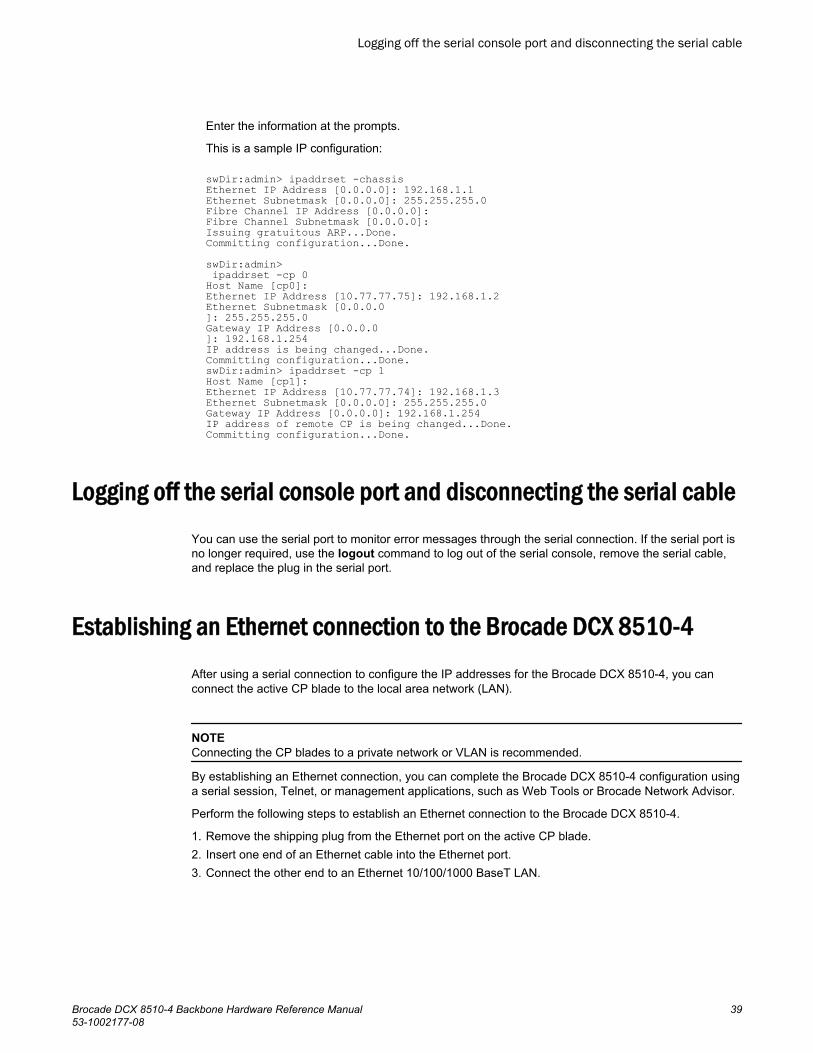
FC8-64 portblade
• 0 through 31 from right to left on the lower set ofports.
• 32 through 63 from right to left on the upper set ofports.
• 0-7, 8-15, 16-23, 24-31, 32-39,40-47, 48-55, and 56-63.
FC16-32 portblade
• 0 through 15 from right to left on the lower set ofports.
• 16 through 31 from right to left on the upper set ofports.
• 0-7, 8-15, 16-23, and 24-31.
FC16-48 portblade
• 0 through 23 from right to left on the lower set ofports.
• 24 through 47 from right to left on the upper set ofports.
• 0-7, 8-15, 16-23, 24-31, 32-39,40-47.
FC16-64 portblade
• 0 through 63 from right to left.
These are QSFP ports 0-15. For supported QSFPs,refer to Qualified transceivers for the FC16-64 portblade and the core blades on page 44.
• 0-7, 8-15, 16-23, 24-31, 32-39,40-47, 48-55, and 56-63.
CR16-4 coreblade
• ICL connectors are numbered from 0 through 7 fromright to left .
Each connector is a group of four 16-Gbps ports. Forsupported QSFPs, refer to Qualified transceivers forthe FC16-64 port blade and the core blades on page44
• Trunk group 0: FC ports 0-3• Trunk group 1: FC ports 4-7
NOTEIndividual FC ports within the sameQSFP port cannot form a trunk. Atrunk has to comprise of individualFC ports from different consecutiveQSFP ports. Only four FC ports fromconsecutive QSFP ports can form atrunk in Brocade DCX 8510-4
FS8-18 blade • The 16 physical Fibre Channel ports on this bladeare numbered 0 through 15 from right to left.
• The two 10/100/1000 BaseT ports are numberedfrom the bottom as GE0 and GE1.
• 0-7 and 8-15.
FX8-24 blade Ports are numbered in groups.
• The FC ports are numbered from 0 through 11 in twohorizontal rows of six ports starting from the lowerright and upper right in the right group of 12 ports.They are labeled FC on the front panel diagram.
• The two 10-GbE ports are 0 and 1 and are in thelower row to the left of the FC ports. They are labeled10GE on the front panel diagram.
• The GbE ports are numbered 0 through 9 and are inboth rows to the left of the FC and 10GE ports. Theyare labeled GE on the front panel diagram.
Up to three FC trunking groups arepermitted. The three groups aredefined as follows:
• Trunk group 0: FC ports 0, 1• Trunk group 1: FC ports 6, 7• Trunk group 2: FC ports 2, 3, 4, 5,
8, 9, 10, 11
Installation of the Brocade DCX 8510-4
28 Brocade DCX 8510-4 Backbone Hardware Reference Manual53-1002177-08

Chassis slotsChassis slots are numbered 1 through 8, from bottom to top when facing the port side of the BrocadeDCX 8510-4. Control processor blades (CP8) can be installed only in slots 4 and 5. Core switch blades(CR16-4) can be installed only in slots 3 and 6. The rest of the slots, 1, 2, 7, and 8, can be filled withport, application, or encryption blades. Unused slots must be filled with blade filler panels to maintainadequate cooling.
Cable managementThe cable management finger assemblies are attached to the chassis on either side of the port side ofthe chassis and allow for simple cable management. The cable management finger assemblies can beinstalled without service disruption.
Route the cables across in front of the blades to keep LEDs visible. Leave at least one meter of slackfor each fiber-optic cable to provide room to remove and replace blades.
NOTE
The minimum radius to which a 50 micron cable can be bent under full tensile load is 5.1 cm (2 in.). Fora cable under no tensile load, that minimum is 3.0 cm (1.2 in.).
CAUTIONBefore plugging a cable into to any port, be sure to discharge the voltage stored on the cable bytouching the electrical contacts to ground surface.
Cables can be organized and managed in a variety of ways, for example, using cable channels on thesides of the cabinet or patch panels to minimize cable management. Following is a list ofrecommendations:
NOTEYou should not use tie wraps with optical cables because they are easily overtightened and candamage the optic fibers.
• Plan for rack space required for cable management before installing the switch.• Leave at least 1 m (3.28 ft) of slack for each port cable. This provides room to remove and replace
the switch, allows for inadvertent movement of the rack, and helps prevent the cables from beingbent to less than the minimum bend radius.
• If you are using Brocade ISL Trunking, consider grouping cables by trunking groups. The cablesused in trunking groups must meet specific requirements, as described in the Fabric OSAdministrator’s Guide .
• For easier maintenance, label the fiber-optic cables and record the devices to which they areconnected.
• Keep LEDs visible by routing port cables and other cables away from the LEDs.• Use Velcro ® type straps to secure and organize fiber-optic cables.
Chassis slots
Brocade DCX 8510-4 Backbone Hardware Reference Manual 2953-1002177-08
NOTE
Do not route the cables in front of the air exhaust vent, which is located at the top of the port side ofthe chassis. If you are using the Port Side Exhaust Kit with your Brocade DCX 8510-4, there is also anexhaust vent at the bottom of the port side of the chassis. Use the cable management fingerassemblies to keep the cables away from this exhaust vent as well.
High-density cablingThe FC8-64 high density port blade cannot use the standard LC cables because the pitch betweenoptics in the new mini-SFP (mSFP) transceiver is smaller than in standard SFPs. Patch cables andpanels can be used to attach standard size cabling to the blade if necessary. The following figureillustrates the mSFP to SFP patch cable. Refer to "Best Practices Guide: High Density CableManagement Solutions" (available at http://www.brocade.com ) for cable management guidelines forhigh-density port solutions, and cable and patch panel part numbers.
FIGURE 4 Cable design for the mSFP patch cables for the FC8-64 high density port blade
1. mSFP connector2. Duplex clip (black)3. 6 mm cable4. SFP connector
Note that the duplex clip on the mSFP end of the cable is black for easier recognition. For a listing ofthe qualified mSFP optical cables for the FC8-64 port blade, refer to Qualified cables for the FC8-64port blade on page 30.
If ISL Trunking is in use, group the cables by trunking group. The ports are color-coded to indicatewhich ports can be used in the same ISL Trunking group: eight ports marked with solid black ovalsalternate with eight ports marked with oval outlines.
Qualified cables for the FC8-64 port bladeThe following table lists the third-party cables that have been qualified for use with the mSFPtransceivers in the FC8-64 high density port blade.
High-density cabling
30 Brocade DCX 8510-4 Backbone Hardware Reference Manual53-1002177-08

Qualified cables for mSFP connections for the FC8-64 high density port blade TABLE 3
Description Length Corning part number Molex partnumber
Amphenol partnumber
Patch cables - mSFP to LC S50502S5120XXXM (XXX= length)
943-99865-1XXXX(XXXX = length)
mSFP LC - standard LC,duplex, multi-mode, OM3,50/125
1 m S50502S5120001M 106273-0525 943-99865-10001
mSFP LC - standard LC,duplex, multi-mode, OM3,50/125
2 m S50502S5120002M 106273-0526 943-99865-10002
mSFP LC - standard LC,duplex, multi-mode, OM3,50/125
3 m S50502S5120003M 106273-0527 943-99865-10003
mSFP LC - standard LC,duplex, multi-mode, OM3,50/125
5 m S50502S5120005M 106273-0528 943-99865-10005
mSFP LC - standard LC,duplex, multi-mode, OM3,50/125
10 m S50502S5120010M 106273-0529 943-99865-10010
Patch cables - mSFP to mSFP S5S502S5120XXXM (XXX= length)
943-99866-1XXXX(XXXX = length)
mSFP LC - mSFP LC, duplex,multi-mode, OM3, 50/125
1 m S5S502S5120001M 106273-0560 943-99866-10001
mSFP LC - mSFP LC, duplex,multi-mode, OM3, 50/125
2 m S5S502S5120002M 106273-0561 943-99866-10002
mSFP LC - mSFP LC, duplex,multi-mode, OM3, 50/125
3 m S5S502S5120003M 106273-0562 943-99866-10003
mSFP LC - mSFP LC, duplex,multi-mode, OM3, 50/125
5 m S5S502S5120005M 106273-0563 943-99866-10005
mSFP LC - mSFP LC, duplex,multi-mode, OM3, 50/125
10 m S5S502S5120010M 106273-0564 943-99866-10010
Trunk cables - mSFP to MTP tbd
mSFP LC - MTP-female, 12fiber, 12" breakout, OM3,50/125
H93S5TE9-BMU-XXXM(XXX = length)
943-99867-1XXXX(XXXX = length)
Installation of the Brocade DCX 8510-4
Brocade DCX 8510-4 Backbone Hardware Reference Manual 3153-1002177-08

Qualified cables for mSFP connections for the FC8-64 high density port blade (Continued)TABLE 3
Description Length Corning part number Molex partnumber
Amphenol partnumber
mSFP LC - MTP-female, 12fiber, 6" breakout, OM3,50/125
2 m 106272-0327
mSFP LC - MTP-female, 24fiber, 12" breakout, OM3,50/125
2 m 106272-0328
Bag of clips (quantity 64) TRIGGER-BP-NP n/a n/a
Cable types supported on the FC16-64 port bladeThe FC16-64 port blade supports simplified cable management using QSFP cables. Each QSFP cablehas four links internally that run at 16-Gbps speed and the cables come in specific predetermined fixedlengths.
The FC16-64 port blade supports the following types of cables:
FIGURE 5 QSFP to QSFP standard cables
1. QSFP MTP connector
FIGURE 6 QSFP-SFP/LC Break-out/Split-out cables
1. QSFP MTP connector2. SFP+ LC connectors
With the support for breakout cables, each port can be in a different mode. Inside the single physicalQSFP port, individual ports can be configured as an E_Port, F_Port or EX_Port. Also, each internalport inside a single physical QSFP can be part of different Logical Switches.
Cable types supported on the FC16-64 port blade
32 Brocade DCX 8510-4 Backbone Hardware Reference Manual53-1002177-08

With the support for breakout cables, trunking can be enabled on ports in a QSFP port group, with portsconnected through breakout cables at the other end.
Installing ICL cablesRefer to Inter-chassis link (ICL) cable removal and replacement on page 96 for the procedure to installthe ICL QSFP cables
Installing ICL cables
Brocade DCX 8510-4 Backbone Hardware Reference Manual 3353-1002177-08

Installing ICL cables
34 Brocade DCX 8510-4 Backbone Hardware Reference Manual53-1002177-08

Logging In and Configuring the Brocade DCX 8510-4
● Configuring the Brocade DCX 8510-4.............................................................................35● Establishing a serial connection to the Brocade DCX 8510-4.........................................36● Logging in to the serial console port............................................................................... 37● Configuring the IP addresses..........................................................................................38● Logging off the serial console port and disconnecting the serial cable........................... 39● Establishing an Ethernet connection to the Brocade DCX 8510-4..................................39● Customizing a switch name............................................................................................ 40● Customizing a chassis name.......................................................................................... 40● Setting the domain ID......................................................................................................40● Setting the date and time................................................................................................ 41● Verifying the PID mode................................................................................................... 43● Determining installed software licenses.......................................................................... 43● Installing transceivers and attaching cables....................................................................43● Managing cables............................................................................................................. 46● Verifying correct operation and backing up the configuration......................................... 47● Powering off the Brocade DCX 8510-4........................................................................... 48
Configuring the Brocade DCX 8510-4The Brocade DCX 8510-4 must be configured before it is connected to the fabric, and all of theconfiguration commands must be entered through the active CP blade. The Brocade DCX 8510-4configuration includes the following parameters:
• IP address and subnet mask for the chassis• IP addresses, host names, subnet masks, and gateway addresses for both CP blades• Switch name• Domain ID for the Brocade DCX 8510-4 (optional)• WWN for the Brocade DCX 8510-4
The Brocade DCX 8510-4 WWN is initially set by the factory to match the license ID (which is based onthe chassis serial number). The WWN can be changed but the license ID cannot be modified.
The configuration information is mirrored to the standby CP blade, which allows the currentconfiguration to remain available even if the active CP blade fails. The configuration information for theBrocade DCX 8510-4 is stored in the WWN cards and the flash memory of the CP blades. Theconfiguration can be backed up to a workstation (uploaded) and then downloaded to the active CPblade if necessary.
NOTEIf the Brocade FS8-18 encryption blade is installed, refer to the Fabric OS Encryption Administrator’sGuide for the procedures to configure the encryption functions.
The following figure illustrates the flow of the basic configuration tasks.
Brocade DCX 8510-4 Backbone Hardware Reference Manual 3553-1002177-08

FIGURE 7 Configuration tasks
Establishing a serial connection to the Brocade DCX 8510-4
To establish a serial connection to the console port on the Brocade DCX 8510-4, complete thefollowing steps.
1. Verify that the Brocade DCX 8510-4 is powered on and that POST is complete by verifying that allpower LED indicators on the port, control processor, and core switch blades display a steady greenlight.
2. Remove the shipping cap from the CONSOLE port on the active CP. Use the serial cable providedwith the Brocade DCX 8510-4 to connect the CONSOLE port on the active CP to a computerworkstation. The active CP blade is indicated by an illuminated (blue) LED.
Establishing a serial connection to the Brocade DCX 8510-4
36 Brocade DCX 8510-4 Backbone Hardware Reference Manual53-1002177-08

NOTE
The CONSOLE port is intended primarily for the initial setting of the IP address and for servicepurposes.
3. Access the Brocade DCX 8510-4 using a terminal emulator application (such as HyperTerminal in aWindows environment or tip in a UNIX environment).
4. Disable any serial communication programs running on the workstation (such as synchronizationprograms).
5. Open a terminal emulator application (such as HyperTerminal on a PC, or term, tip, or kermit in aUNIX environment), and configure the application as follows:
• In a Windows environment:
Parameter Value
Bits per second 9600
Data bits 8
Parity None
Stop bits 1
Flow control None
• In a UNIX environment, enter the following string at the prompt:
tip /dev/ttyb -9600If ttyb is already in use, use ttya instead and enter the following string at the prompt:
tip /dev/ttya -9600When the terminal emulator application stops reporting information, press Enter. You receive thefollowing login prompt:
CP0 Console Login:6. Proceed to the next task.
Logging in to the serial console port
To log in to the Brocade DCX 8510-4 through the serial connection, follow these steps.
1. Log in to the Brocade DCX 8510-4 as admin. The default password is password. At the initial login,you are prompted to enter new admin and user passwords. Make sure to write down the newpasswords and keep this information in a secure location.
Fabric OS (swDir)swDir login: adminPassword:Please change your passwords now.Use Control-C to exit or press 'Enter' key to proceed.
Logging in to the serial console port
Brocade DCX 8510-4 Backbone Hardware Reference Manual 3753-1002177-08

swDir:admin>2. (Optional) Modify passwords. To skip modifying the password, press Ctrl+C. For more information
on passwords, refer to the Fabric OS Administrator's Guide.
NOTEPasswords can be 8 to 40 characters long. They must begin with an alphabetic character. They caninclude numeric characters, the period (.), and the underscore (_) only. Passwords are case-sensitive, and they are not displayed when you enter them on the command line. For moreinformation on passwords, refer to the Fabric OS Administrator's Guide.
Configuring the IP addresses
The Brocade DCX 8510-4 requires three IP addresses, which are configured using the ipAddrSetcommand. IP addresses are required for both CP blades (CP0 and CP1) and for the chassismanagement IP (shown as SWITCH under the ipAddrShow command) in the Brocade DCX 8510-4.
NOTEThe default IP addresses and host names for the Brocade DCX 8510-4 are:
• 10.77.77.75 / CP0 (the CP blade in slot at the time of configuration)• 10.77.77.74 / CP1 (the CP blade in slot at the time of configuration)
NOTE
Resetting an IP address while the Brocade DCX 8510-4 has active IP traffic or has management andmonitoring tools running, such as DCFM, Fabric Watch, and SNMP, can cause traffic to be interruptedor stopped.
Complete the following steps to set the IP addresses for the Brocade DCX 8510-4.
1. Log in to the active CP as admin using the serial cable connection.2. Set up the Brocade DCX 8510-4 IP address by entering the ipaddrset -chassis command:
swDir:admin> ipAddrSet -chassisEnter the information at the prompts. Specify the -chassis IP address. The -sw 0 IP address is notvalid on this chassis.
NOTEThe addresses 10.0.0.0 through 10.0.0.255 are reserved and used internally by the Brocade DCX8510-4. External IPs must not use these addresses.
3. Set up the CP0 IP address by entering the ipaddrset -cp 0 command:
swDir:admin> ipAddrSet -cp 0Enter the information at the prompts.
4. Set up the CP1 IP address by entering the ipaddrset -cp 1 command:
swDir:admin> ipAddrSet -cp 1
Configuring the IP addresses
38 Brocade DCX 8510-4 Backbone Hardware Reference Manual53-1002177-08
Enter the information at the prompts.
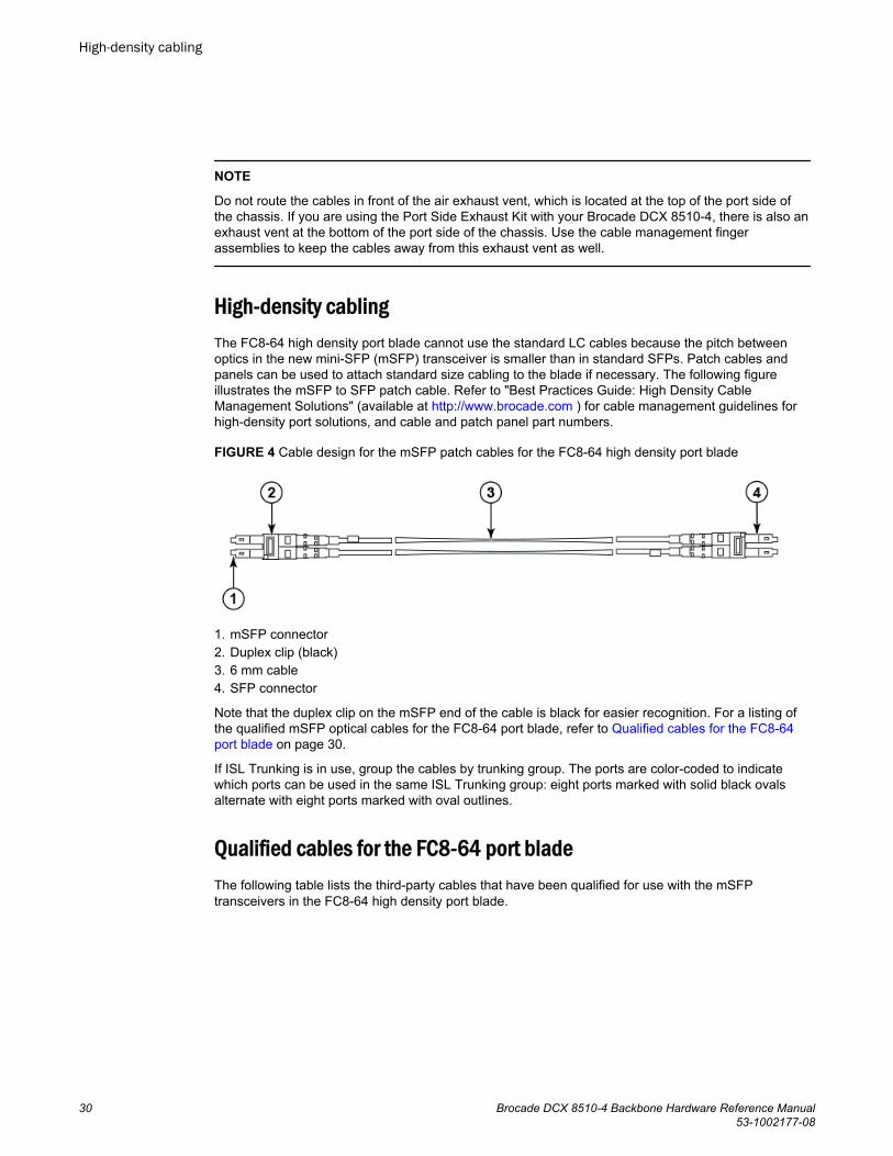
This is a sample IP configuration:
swDir:admin> ipaddrset -chassisEthernet IP Address [0.0.0.0]: 192.168.1.1Ethernet Subnetmask [0.0.0.0]: 255.255.255.0Fibre Channel IP Address [0.0.0.0]: Fibre Channel Subnetmask [0.0.0.0]: Issuing gratuitous ARP...Done.Committing configuration...Done.swDir:admin> ipaddrset -cp 0Host Name [cp0]:Ethernet IP Address [10.77.77.75]: 192.168.1.2Ethernet Subnetmask [0.0.0.0]: 255.255.255.0Gateway IP Address [0.0.0.0]: 192.168.1.254IP address is being changed...Done.Committing configuration...Done.swDir:admin> ipaddrset -cp 1Host Name [cp1]:Ethernet IP Address [10.77.77.74]: 192.168.1.3Ethernet Subnetmask [0.0.0.0]: 255.255.255.0Gateway IP Address [0.0.0.0]: 192.168.1.254IP address of remote CP is being changed...Done.Committing configuration...Done.
Logging off the serial console port and disconnecting the serial cableYou can use the serial port to monitor error messages through the serial connection. If the serial port isno longer required, use the logout command to log out of the serial console, remove the serial cable,and replace the plug in the serial port.
Establishing an Ethernet connection to the Brocade DCX 8510-4
After using a serial connection to configure the IP addresses for the Brocade DCX 8510-4, you canconnect the active CP blade to the local area network (LAN).
NOTEConnecting the CP blades to a private network or VLAN is recommended.
By establishing an Ethernet connection, you can complete the Brocade DCX 8510-4 configuration usinga serial session, Telnet, or management applications, such as Web Tools or Brocade Network Advisor.
Perform the following steps to establish an Ethernet connection to the Brocade DCX 8510-4.
1. Remove the shipping plug from the Ethernet port on the active CP blade.2. Insert one end of an Ethernet cable into the Ethernet port.3. Connect the other end to an Ethernet 10/100/1000 BaseT LAN.
Logging off the serial console port and disconnecting the serial cable
Brocade DCX 8510-4 Backbone Hardware Reference Manual 3953-1002177-08

The Brocade DCX 8510-4 can be accessed through a remote connection using the command linevia Telnet or any of the management tools, such as Web Tools or Brocade Network Advisor.
4. To complete any additional Brocade DCX 8510-4 configuration procedures through a Telnetsession, log in to the Brocade DCX 8510-4 by Telnet, using the admin login. The default passwordis password.
Customizing a switch name
The switch name of the Brocade DCX 8510-4 can be up to 30 characters long using Fabric OSrelease 7.0.0 or later; can include letters, numbers, hyphens, and underscore characters; and mustbegin with a letter.
NOTEChanging the name causes a domain address format RSCN to be issued.
1. Enter switchName followed by the new name in double quotes.
swDir:admin> switchName "swModularSwitch5"Committing configuration...Done.swModularSwitch5:admin>
2. Record the new name for reference.
Customizing a chassis name
The chassis name of the Brocade DCX 8510-4 can be up to 15 characters long; can include letters,numbers, hyphens, and underscore characters; and must begin with a letter.
1. Enter chassisName followed by the new name in double quotes.
switch:admin> chassisname "DCX8510_chassis"Committing configuration...Done.
2. Enter chassisName by itself to show the name.
switch:admin> chassisnameDCX8510_chassis
3. Record the new name for reference.
Setting the domain ID
Each switch in the fabric must have a unique domain ID. The domain ID can be manually set throughthe configure command or can be automatically set. The default domain ID for the Brocade DCX8510-4 is 1. Use the fabricShow command to view the already assigned domain IDs.
1. Enter switchDisable to disable the Brocade DCX 8510-4.2. Enter configure.
Customizing a switch name
40 Brocade DCX 8510-4 Backbone Hardware Reference Manual53-1002177-08

3. Enter y at the Fabric parameters prompt:
Fabric parameters (yes, y, no, n): [no] y4. Enter a unique domain ID:
Domain: (1.239) [1] 35. Complete the remaining prompts or press Ctrl+D to accept the settings and exit.6. Enter switchEnable to re-enable the Brocade DCX 8510-4.
Setting the date and timeThe date and time settings are used for logging events. Switch operation does not depend on the dateand time; a switch with an incorrect date and time value still functions properly. However, because thedate and time are used for logging, error detection, and troubleshooting, they should be set correctly.
Setting the dateTo set the date, follow these steps.
1. If necessary, log on to the Brocade DCX 8510-4 by Telnet, using the admin account.
The default password is password.2. Enter the date command, using the following syntax:
date "mmddHHMMyy"The values are:
• mm is the month; valid values are 01 through 12.• dd is the date; valid values are 01 through 31.• HH is the hour; valid values are 00 through 23.• MM is minutes; valid values are 00 through 59.• yy is the year; valid values are 00 through 99 (values greater than 69 are interpreted as 1970
through 1999, and values less than 70 are interpreted as 2000 through 2069).
switch:admin> dateFri Sep 28 17:01:48 UTC 2010switch:admin> date "0927123010"Thu Sep 27 12:30:00 UTC 2010switch:admin>
Setting the time zoneYou must perform the procedure on all chassis for which the time zone must be set. However, you onlyneed to set the time zone once on each switch, because the value is written to nonvolatile memory.
Use one of the two following procedures to set the time zone.
The following procedure describes how to set the current time zone using timezone_fmt mode toCentral Standard time.
1. Log in to the switch using the default password, which is password.2. Enter the tsTimeZone command as follows:
switch:admin> tstimezone [--interactive]/ [, timezone_fmt]Use timezone_fmt to set the time zone by Country/City or by time zone ID, such as PST.
Setting the date and time
Brocade DCX 8510-4 Backbone Hardware Reference Manual 4153-1002177-08

The following example shows how to change the time zone to US/Central.
switch:admin> tstimezoneTime Zone : US/Pacificswitch:admin> tstimezone US/Centralswitch:admin> tstimezoneTime Zone : US/Central
The following procedure describes how to set the current time zone usinginteractive mode to Pacific Standard Time.
1. Enter the tsTimeZone command as follows:switch:admin> tstimezone --interactiveYou are prompted to select a general location.Please identify a location so that time zone rules can be set correctly.
2. Enter the appropriate number or Ctrl+D to quit.3. At the prompt, select a country location.4. At the prompt, enter the appropriate number to specify the time zone region
or Ctrl+D to quit.
Synchronizing local timeTo synchronize the local time of the principal or primary switch with that of an external NTP server,follow these steps.
1. If necessary, log on to the switch by Telnet, using the admin account.2. Enter the tsClockServer command:
switch:admin> tsclockserver "<ntp1;ntp2>"In this syntax, ntp1 is the IP address or DNS name of the first NTP server, which the switch must beable to access. The variable ntp2 is the second NTP server and is optional. The operand"<ntp1;ntp2>" is optional; by default, this value is LOCL, which uses the local clock of the principalor primary switch as the clock server.
The tsClockServer command accepts multiple server addresses in IPv4, IPv6, or DNS nameformats. When multiple NTP server addresses are passed, tsClockServer sets the first obtainableaddress as the active NTP server. The rest will be stored as backup servers that can take over if theactive NTP server fails. The principal or primary FCS switch synchronizes its time with the NTPserver every 64 seconds.
switch:admin> tsclockserverLOCLswitch:admin> tsclockserver "132.163.135.131" switch:admin> tsclockserver132.163.135.131switch:admin>The following example shows how to set up more than one NTP server using a DNS name:
switch:admin> tsclockserver "10.32.170.1;10.32.170.2;ntp.localdomain.net"Updating Clock Server configuration...done.Updated with the NTP serversChanges to the clock server value on the principal or primary FCS switch are propagated to all switches in the fabric
Synchronizing local time
42 Brocade DCX 8510-4 Backbone Hardware Reference Manual53-1002177-08

Verifying the PID modeBefore connecting the Brocade DCX 8510-4 to the fabric, verify that the WWN-based persistent portidentifier (PID) feature on the Brocade DCX 8510-4 matches the other switches in the fabric. Thisparameter must be identical for all switches in the fabric and is set using the configure command asshown in the following example:
switch:admin>configureConfigure...Fabric parameters (yes, y, no, n): [no] yDomain: (1..239) [1]Enable a 256 Area Limit (0 = No, 1 = Zero Based Area Assignment, 2 = Port Based Area Assignment): (0..2) [0] 1WWN Based persistent PID (yes, y, no, n): [no] yes<command output truncated>You can check the PID setting using the configshow command as in the following example. You canuse the | grep -i pid qualifier to pinpoint the PID information.
switch:admin> configshow | grep -i pidfabric.ops.mode.pidFormat:1fabric.wwnPidMode:1The 1 indicates that the WWN-based persistent PID feature is enabled. The default value is 0 fordisabled.
Determining installed software licensesDepending on the vendor agreement, certain licenses are factory installed on the Brocade DCX 8510-4.To determine which licenses are enabled, use the licenseShow command.
swDir:admin> licenseshowAAbbccDDeeFFeeGG: Web license Zoning license Extended Fabric license Fabric Watch license Performance Monitor license Trunking license Security licenseIn this example, the license key is AAbbccDDeeFFeeGG. Keep a copy of the license key for reference.
The 64-bit chassis ID is required to obtain and activate licenses for the Brocade DCX 8510-4. Thechassis ID is available through the licenseIdShow command. The licenseShow and licenseIdShowcommands must be entered on the active CP blade. Refer to the Fabric OS Administrator's Guide formore information.
Installing transceivers and attaching cablesThe following two sets of steps cover the installation of transceivers and cables for most SFPs and forQSFPs.
Verifying the PID mode
Brocade DCX 8510-4 Backbone Hardware Reference Manual 4353-1002177-08

Installing SFP+ and mSFP transceivers and cablesComplete the following steps to install SFP-type optical transceivers.
NOTEmSFP transceivers are compatible only with the FC8-64 port blade. While they will fit in other blades,this configuration is unsupported and will generate an error.
1. Add the optical transceivers and cables to the Fibre Channel ports.
The ports are color-coded to indicate which can be used in the same port group for trunking(trunking port groups can be up to 8 ports). The ports and cables used in trunking groups must meetspecific requirements. Refer to the Fabric OS Administrator's Guide.
2. Position one of the optical transceivers so that the key is oriented correctly to the port. Insert thetransceiver into the port until it is firmly seated and the latching mechanism clicks.
Transceivers are keyed so that they can only be inserted with the correct orientation. If a transceiverdoes not slide in easily, ensure that it is correctly oriented.
3. Position a cable so that the key (the ridge on one side of the cable connector) is aligned with theslot in the transceiver. Insert the cable into the transceiver until the latching mechanism clicks.
Cables are keyed so that they can be inserted in only one way. If a cable does not slide in easily,ensure that it is correctly oriented.
4. Repeat steps 1 through 3 for the remaining ports.5. Organize the cables. Refer to Managing cables on page 46.6. Verify the Brocade DCX 8510-4 and port status using the switchShow command.7. Verify fabric connectivity using the fabricShow command.
Qualified transceivers for the FC16-64 port blade and the core bladesThe following table shows the qualified transceivers for the FC16-64 port blade and the core blades.
Qualified transceivers for FC16-64 port blade and the core bladesTABLE 4
Brocade partnumber
Part type Cable length Port speeds Supported blades
57-1000294-01 QSFP transceiver 100 m OM4 Auto-negotiable 4-, 8-,and 16-Gbps
FC16-64
57-1000267-01 QSFP transceiver 100 m OM4 Only fixed 16-Gbps CR16-4/8
57-0000090-01 QSFP transceiver 50 m OM3
NOTEThe QSFP transceivers supported on FC16-64 port blade are not interchangeable with QSFPtransceivers supported on the core blades.
Installing SFP+ and mSFP transceivers and cables
44 Brocade DCX 8510-4 Backbone Hardware Reference Manual53-1002177-08

Installing QSFP transceivers and cablesFollow these steps to install the QSFPs and cables in the FC16-64 port blades and 16-Gbps coreblades. In the core blades, these transceivers and cables are used to form the inter-chassis links (ICLs)with neighboring DCX 8510 Backbones. The transceivers should be installed in the blades beforeconnecting the cables. Because each QSFP contains four 16-Gbps ports, be aware that any problemswith one port could affect all four ports in the quad if the QSFP must be replaced.
NOTEEven though the installation and removal procedures are the same for QSFP ports in FC16-64 portblades and the core blades, the physical QSFP transceivers designed for FC16-64 are not compatiblewith the QSFP transceivers designed for the core blades. They are not interchangeable.
1. Position one of the QSFP transceivers so that the key is oriented correctly to the port. Insert thetransceiver into the port until it is firmly seated.
Transceivers are keyed so that they can only be inserted with the correct orientation. If a transceiverdoes not slide in easily, ensure that it is correctly oriented.
When the transceiver is correctly seated, the status LED will flash amber several times and then turnsolid amber.
2. Remove the protective cap from the special QSFP cable and insert it into the transceiver until it isfirmly seated.
The cables are also keyed to fit into the transceivers correctly.
When the cable is correctly seated, the status LED will change from amber to green.
Repeat steps 1 and 2 for the remaining QSFP ports.3. Organize the cables. Refer to Managing cables on page 46.4. Verify the Brocade DCX 8510-4 and connector and port status using the switchShow -qsfp
command.
The following example is from a DCX 8510-4 with a core blade installed in slot 3.
Note that the State reported for an unconnected QSFP (shown QSFP 0 and Ports 0-3 in the exampleis No_SigDet. This is different from the State of No_Synch that is reported for regular SFPs that areunconnected.
QSFP 7 (ports 3/28-3/31, Index 748-751) in the following example shows the results for a connectedQSFP.
switch:FID128:admin> switchshow -qsfpswitchName: switch nameswitchType: 121.3switchState: OnlineswitchMode: NativeswitchRole: SubordinateswitchDomain: 75switchId: fffc4bswitchWwn: 10:00:00:05:1e:4f:eb:00zoning: ON (zoning name)switchBeacon: OFFFC Router: OFFAllow XISL Use: OFFLS Attributes: [FID: 128, Base Switch: No, Default Switch: Yes, Address Mode 0]Index Slot Port QSFP Address Media Speed State Proto=============================================================256 3 0 0 ------ id 16G No_SigDet FC257 3 1 0 ------ id 16G No_SigDet FC258 3 2 0 ------ id 16G No_SigDet FC259 3 3 0 ------ id 16G No_SigDet FC260 3 4 1 ------ -- 16G No_Module FC
Installing QSFP transceivers and cables
Brocade DCX 8510-4 Backbone Hardware Reference Manual 4553-1002177-08

261 3 5 1 ------ -- 16G No_Module FC262 3 6 1 ------ -- 16G No_Module FC263 3 7 1 ------ -- 16G No_Module FC264 3 8 2 ------ -- 16G No_Module FC265 3 9 2 ------ -- 16G No_Module FC266 3 10 2 ------ -- 16G No_Module FC267 3 11 2 ------ -- 16G No_Module FC268 3 12 3 ------ -- 16G No_Module FC269 3 13 3 ------ -- 16G No_Module FC270 3 14 3 ------ -- 16G No_Module FC271 3 15 3 ------ -- 16G No_Module FC736 3 16 4 ------ -- 16G No_Module FC737 3 17 4 ------ -- 16G No_Module FC738 3 18 4 ------ -- 16G No_Module FC739 3 19 4 ------ -- 16G No_Module FC740 3 20 5 ------ -- 16G No_Module FC741 3 21 5 ------ -- 16G No_Module FC742 3 22 5 ------ -- 16G No_Module FC743 3 23 5 ------ -- 16G No_Module FC744 3 24 6 ------ -- 16G No_Module FC745 3 25 6 ------ -- 16G No_Module FC746 3 26 6 ------ -- 16G No_Module FC747 3 27 6 ------ -- 16G No_Module FC748 3 28 7 ------ id 16G Online FC E-Port 10:00:00:05:1e:39:e4:5a trunkmaster name (Trunk master)749 3 29 7 ------ id 16G Online FC E-Port 10:00:00:05:1e:39:e4:5a trunkmaster name (Trunk master)750 3 30 7 ------ id 16G Online FC E-Port 10:00:00:05:1e:39:e4:5a trunkmaster name (Trunk master)751 3 31 7 ------ id 16G Online FC E-Port 10:00:00:05:1e:39:e4:5a trunkmaster name (Trunk master)
Managing cablesCables can be organized and managed in a variety of ways, for example, using cable channels on theport sides of the cabinet or patch panels to minimize cable management. With the horizontalorientation of the blades in the Brocade DCX 8510-4, a pair of vertical cable management fingerassemblies have been provided to keep the cables from hanging down in front of other blades.
Following is a list of recommendations:
• Leave at least 1 m (3.28 ft) of slack for each port cable. This provides room to remove and replacethe Brocade DCX 8510-4, allows for inadvertent movement of the rack, and helps prevent thecables from being bent to less than the minimum bend radius.
• The minimum bend radius should be no smaller than ten times the cable radius. The minimumradius to which a 50 micron cable can be bent under full tensile load is 5.1 cm (2 in.). For a cableunder no tensile load, that minimum is 3.0 cm (1.2 in.).
• If ISL Trunking is in use, group the cables by trunking group. The ports are color-coded to indicatewhich ports can be used in the same ISL Trunking group: eight ports marked with solid black ovalsalternate with eight ports marked with oval outlines.
• Generally, Velcro ® type cable restraints are recommended to avoid creating sharp bends in thecables. Do not use tie wraps with optical cables because they are easily overtightened and candamage the optic fibers.
• For easier maintenance, label the fiber-optic cables and record the devices to which they areconnected.
• Do not route cables in front of the air exhaust vents.• Keep LEDs visible by routing port cables and other cables away from the LEDs.
Managing cables
46 Brocade DCX 8510-4 Backbone Hardware Reference Manual53-1002177-08

NOTERefer to "Cabling Best Practices" (available at http://www.brocade.com ) for cable managementguidelines.
For the procedure to install the ICL cables, refer to Inter-chassis link (ICL) cable removal andreplacement on page 96
Verifying correct operation and backing up the configuration
To verify correct operation and back up the Brocade DCX 8510-4 configuration, follow these steps. Forinformation about LED patterns, refer to Determining the status of a port or application blade on page52.
Complete the following steps to back up the configuration for the Brocade DCX 8510-4.
1. Check the LEDs to verify that all components are functional.2. If necessary, log in to the switch by Telnet, using the admin account.3. Verify the correct operation of the Brocade DCX 8510-4 by entering the switchShow command from
the workstation. This command provides information about switch and port status.4. Verify the correct operation of the Brocade DCX 8510-4 in the fabric by entering the fabricShow
command from the workstation. This command provides general information about the fabric.5. To back up the configuration, run the following two steps:
a) Enter the configupload -vf command. This command uploads the Brocade DCX 8510-4virtual fabric data.
b) Enter the configupload command. This command uploads the Brocade DCX 8510-4configuration.
6. You can run the following commands to see additional configuration information that you can copy toa file to save:
• configShow• ipaddrShow• licenseShow• switchShow
Alternatively, you can save the configuration file to a Brocade USB device by using the usbstoragecommand.
NOTEPasswords are not saved in the configuration file, and are not uploaded during a configurationupload.
NOTEIt is recommended that the configuration be backed up on a regular basis to ensure that a completeconfiguration is available for downloading to a replacement Brocade DCX 8510-4.
Verifying correct operation and backing up the configuration
Brocade DCX 8510-4 Backbone Hardware Reference Manual 4753-1002177-08

Powering off the Brocade DCX 8510-4
Perform the following steps to power off the Brocade DCX 8510-4.
1. Shut down the Brocade DCX 8510-4 using the sysShutdown command.
switch::admin> sysshutdownThis command will shutdown the operating systems on your switch.You are required to power-cycle the switch in order to restore operation.Are you sure you want to shutdown the switch [y/n]?yHA is disabledStopping blade 1 Shutting down the blade....Stopping blade 2 Shutting down the blade....Stopping blade 8 Shutting down the blade....Broadcast message from root (pts/1) Tue Aug 23 14:23:06 2010...The system is going down for system halt NOW !!
2. Power off the chassis by flipping the AC power switches on the power supplies to O (LEDs insideAC power switches should turn off). To maintain the ground connections, leave power cordsconnected to the power supplies and to the electrical outlets.
Powering off the Brocade DCX 8510-4
48 Brocade DCX 8510-4 Backbone Hardware Reference Manual53-1002177-08

Monitoring System Components
● Monitoring overview........................................................................................................ 49● Determining the status of a port or application blade......................................................52● Determining the status of a control processor blade (CP8)............................................ 58● Determining the status of a core switch blade (CR16-4).................................................60● Determining the status of a power supply....................................................................... 61● Determining the status of a blower assembly................................................................. 62● Determining the status of a WWN card...........................................................................63
Monitoring overviewThe Brocade DCX 8510-4 is engineered for reliability and requires no routine operational steps ormaintenance. This chapter provides information about determining the status of each component usingLEDs and CLI commands. Refer to the Web Tools Administrator's Guide and the Fabric OSAdministrator's Guide for additional information.
There are two commands that can be especially helpful in monitoring the health of the Brocade DCX8510-4. These commands are switchShow and chassisShow.
Note in the switchShow command the new switchType for the Brocade DCX 8510-4 as well as the 16-Gbps speed identification for capable ports. The output has been truncated to reduce informationduplication.
DCX-4_130:admin> switchshowswitchName: DCX-4_130switchType: 121.3switchState: OnlineswitchMode: NativeswitchRole: PrincipalswitchDomain: 130switchId: fffc82switchWwn: 10:00:00:05:33:03:2c:00zoning: ON (BB)switchBeacon: OFFFC Router: ONFC Router BB Fabric ID: 10Address Mode: 0Index Slot Port Address Media Speed State Proto======================================================= 0 1 0 820000 id N8 Online FC F-Port 10:00:00:05:1e:f8:a0:b4 1 1 1 820100 id N8 Online FC F-Port 10:00:00:05:33:26:0e:65 2 1 2 820200 id N8 Online FC F-Port 10:00:00:05:33:48:5e:f5 3 1 3 820300 id N8 Online FC F-Port 10:00:00:05:1e:f8:a0:b3 4 1 4 820400 id N8 Online FC F-Port 10:00:00:05:33:26:10:15 5 1 5 820500 id N8 Online FC F-Port 10:00:00:05:1e:f8:a0:b1 6 1 6 820600 id N8 Online FC F-Port 10:00:00:05:33:48:5e:d0 7 1 7 820700 id N8 Online FC F-Port 10:00:00:05:33:26:df:6b 8 1 8 820800 id N8 Online FC F-Port 10:00:00:05:33:26:df:6a 9 1 9 820900 id N8 Online FC F-Port 10:00:00:05:33:48:6b:ea 10 1 10 820a00 id N8 Online FC F-Port 10:00:00:05:33:26:10:28 11 1 11 820b00 id N8 Online FC F-Port 10:00:00:05:33:26:10:73 12 1 12 820c00 id N8 Online FC F-Port 10:00:00:05:33:48:5e:d1 13 1 13 820d00 id N8 Online FC F-Port 10:00:00:05:33:26:10:29 14 1 14 820e00 id N8 Online FC F-Port 10:00:00:05:1e:f9:72:47 15 1 15 820f00 id N8 Online FC F-Port 10:00:00:05:33:26:0e:8a 16 1 16 821000 id N8 Online FC F-Port 10:00:00:05:33:26:0e:8b 17 1 17 821100 id N8 Online FC F-Port 10:00:00:05:33:48:6b:eb
Brocade DCX 8510-4 Backbone Hardware Reference Manual 4953-1002177-08

18 1 18 821200 id N8 Online FC F-Port 10:00:00:05:1e:f9:72:46 19 1 19 821300 id N8 Online FC F-Port 10:00:00:05:33:26:10:14 20 1 20 821400 id N8 Online FC F-Port 10:00:00:05:33:26:0e:64 21 1 21 821500 id N8 Online FC F-Port 10:00:00:05:33:26:10:72 22 1 22 821600 id N8 Online FC F-Port 10:00:00:05:33:48:5e:f4 23 1 23 821700 id N8 Online FC F-Port 10:00:00:05:1e:f8:a0:b2 24 1 24 821800 -- N16 No_Module FC 25 1 25 821900 -- N16 No_Module FC 26 1 26 821a00 -- N16 No_Module FC 27 1 27 821b00 -- N16 No_Module FC 28 1 28 821c00 id N8 No_Light FC 29 1 29 821d00 id N8 No_Light FC 30 1 30 821e00 id N8 No_Light FC 31 1 31 821f00 id N8 No_Light FC 32 1 32 822000 id N8 No_Light FC 33 1 33 822100 id N8 No_Light FC 34 1 34 822200 id N8 No_Light FC 35 1 35 822300 id N8 No_Light FC 36 1 36 822400 id N8 No_Light FC 37 1 37 822500 id N8 No_Light FC 38 1 38 822600 id N8 No_Light FC 39 1 39 822700 id N8 No_Light FC 40 1 40 822800 id N8 No_Light FC 41 1 41 822900 id N8 No_Light FC 42 1 42 822a00 id N8 No_Light FC 43 1 43 822b00 id N8 No_Light FC 44 1 44 822c00 id N8 No_Light FC 45 1 45 822d00 -- N16 No_Module FC 46 1 46 822e00 -- N16 No_Module FC 47 1 47 822f00 -- N16 No_Module FC 256 3 0 ------ id 16G No_SigDet FC 257 3 1 ------ id 16G No_SigDet FC 258 3 2 ------ id 16G No_SigDet FC 259 3 3 ------ id 16G No_SigDet FC 260 3 4 ------ id 16G No_SigDet FC 261 3 5 ------ id 16G No_SigDet FC 262 3 6 ------ id 16G No_SigDet FC 263 3 7 ------ id 16G No_SigDet FC 264 3 8 ------ id 16G No_SigDet FC 265 3 9 ------ id 16G No_SigDet FC<output truncated>DCX-4_130:admin>
Note in the chassisShow command the Chassis Family designation for the Brocade DCX 8510-4along with specific information about every field-replaceable unit in the chassis.
DCX-4_130:admin> chassisshowChassis Family: DCX8510-4Chassis Backplane Revision: 2SW BLADE Slot: 1Header Version: 2Power Consume Factor: -160Power Usage (Watts): -106Factory Part Num: 60-1002144-02Factory Serial Num: BQB0345F00XManufacture: Day: 19 Month: 11 Year: 2010Update: Day: 29 Month: 3 Year: 2011Time Alive: 32 daysTime Awake: 0 daysCP BLADE Slot: 4Header Version: 2Power Consume Factor: -40Factory Part Num: 60-1000376-08Factory Serial Num: AHJ0420F08KManufacture: Day: 21 Month: 5 Year: 2010Update: Day: 29 Month: 3 Year: 2011Time Alive: 229 daysTime Awake: 0 daysCP BLADE Slot: 5Header Version: 2Power Consume Factor: -40Factory Part Num: 60-1000376-08Factory Serial Num: AHJ0420F086Manufacture: Day: 21 Month: 5 Year: 2010Update: Day: 29 Month: 3 Year: 2011Time Alive: 229 days
Monitoring System Components
50 Brocade DCX 8510-4 Backbone Hardware Reference Manual53-1002177-08

Time Awake: 0 daysCORE BLADE Slot: 3Header Version: 2Power Consume Factor: -135Power Usage (Watts): -88Factory Part Num: 60-1002142-02Factory Serial Num: BQD0344F01KManufacture: Day: 18 Month: 11 Year: 2010Update: Day: 29 Month: 3 Year: 2011Time Alive: 47 daysTime Awake: 0 daysCORE BLADE Slot: 6Header Version: 2Power Consume Factor: -135Power Usage (Watts): -87Factory Part Num: 60-1002099-01Factory Serial Num: BQD0337F00AManufacture: Day: 16 Month: 9 Year: 2010Update: Day: 29 Month: 3 Year: 2011Time Alive: 77 daysTime Awake: 0 daysAP BLADE Slot: 7Header Version: 2Power Consume Factor: -250Factory Part Num: 60-1001157-21Factory Serial Num: ATM0431F008Manufacture: Day: 20 Month: 9 Year: 2010Update: Day: 29 Month: 3 Year: 2011Time Alive: 4 daysTime Awake: 0 daysSW BLADE Slot: 8Header Version: 2Power Consume Factor: -140Power Usage (Watts): -95Factory Part Num: 60-1002145-02Factory Serial Num: BQA0344F00SManufacture: Day: 6 Month: 11 Year: 2010Update: Day: 29 Month: 3 Year: 2011Time Alive: 32 daysTime Awake: 0 daysPOWER SUPPLY Unit: 1Header Version: 2Power Consume Factor: 2000Factory Part Num: 23-0000067-01Factory Serial Num: AGC2M03FR4PManufacture: Day: 7 Month: 6 Year: 2010Update: Day: 29 Month: 3 Year: 2011Time Alive: 229 daysTime Awake: 0 daysPOWER SUPPLY Unit: 2Header Version: 2Power Consume Factor: 2000Factory Part Num: 23-0000067-01Factory Serial Num: AGC2M03FR7TManufacture: Day: 7 Month: 6 Year: 2010Update: Day: 29 Month: 3 Year: 2011Time Alive: 221 daysTime Awake: 0 daysFAN Unit: 1Header Version: 2Power Consume Factor: -126Factory Part Num: 60-1000384-09Factory Serial Num: AGB0623F0AMManufacture: Day: 7 Month: 6 Year: 2010Update: Day: 29 Month: 3 Year: 2011Time Alive: 229 daysTime Awake: 0 daysFAN Unit: 2Header Version: 2Power Consume Factor: -126Factory Part Num: 60-1000384-09Factory Serial Num: AGB0623F0AKManufacture: Day: 7 Month: 6 Year: 2010Update: Day: 29 Month: 3 Year: 2011Time Alive: 229 daysTime Awake: 0 daysWWN Unit: 1Header Version: 2
Monitoring System Components
Brocade DCX 8510-4 Backbone Hardware Reference Manual 5153-1002177-08

Power Consume Factor: -1Factory Part Num: 60-1000888-05Factory Serial Num: ANN2524F01NManufacture: Day: 7 Month: 6 Year: 2010Update: Day: 29 Month: 3 Year: 2011Time Alive: 229 daysTime Awake: 0 daysID: BRD0000CAPart Num: SLKWRM0000X4SWWN Unit: 2Header Version: 2Power Consume Factor: -1Factory Part Num: 60-1000888-05Factory Serial Num: ANQ0417F03PManufacture: Day: 7 Month: 6 Year: 2010Update: Day: 29 Month: 3 Year: 2011Time Alive: 229 daysTime Awake: 0 daysChassis Factory Serial Num: ANP2523F00EDCX-4_130:admin>
Determining the status of a port or application blade
Use the following procedure to determine the status of a port or application blade.
1. Check the LEDs on the blade.Refer to Blade illustrations on page 52.
The LED patterns may temporarily change during POST and other diagnostic tests. For informationabout how to interpret the LED patterns, refer to the table following the blade descriptions.
2. Check the blade status by entering slotShow.
Blade illustrationsThis section illustrates the following port blades:
• The FC8-32E port blade.• The FC8-48E port blade.• The FC8-64 port blade.• The FC16-32 port blade.• The FC16-48 port blade.• The FC16-64 port blade.• The FS8-18 encryption blade.• The FX8-24 extension blade.
Determining the status of a port or application blade
52 Brocade DCX 8510-4 Backbone Hardware Reference Manual53-1002177-08

FIGURE 8 FC8-32E port blade
1. Blade status LED2. Blade power LED3. Fibre Channel port4. Port status LED
FIGURE 9 FC8-48E port blade
1. Blade status LED2. Blade power LED3. Fibre Channel port4. Port status LED
Monitoring System Components
Brocade DCX 8510-4 Backbone Hardware Reference Manual 5353-1002177-08
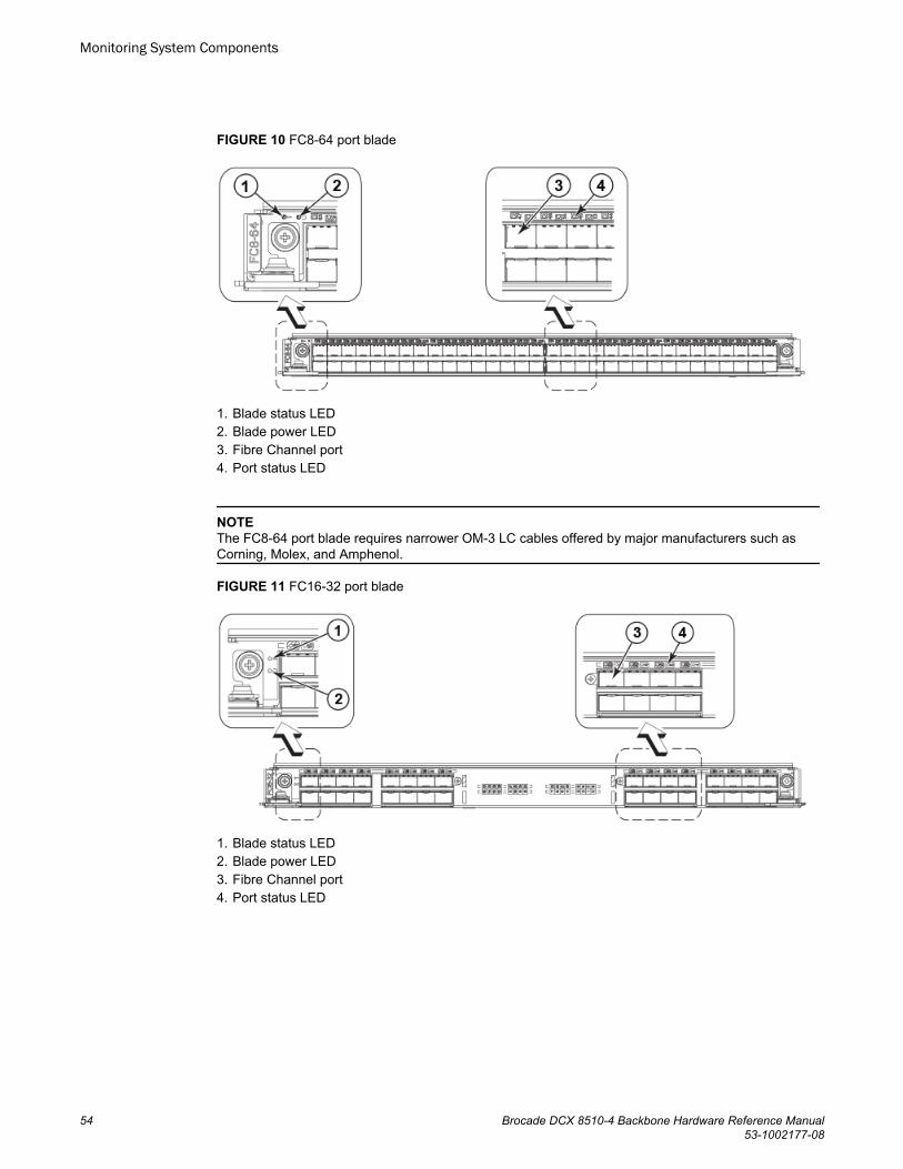
FIGURE 10 FC8-64 port blade
1. Blade status LED2. Blade power LED3. Fibre Channel port4. Port status LED
NOTEThe FC8-64 port blade requires narrower OM-3 LC cables offered by major manufacturers such asCorning, Molex, and Amphenol.
FIGURE 11 FC16-32 port blade
1. Blade status LED2. Blade power LED3. Fibre Channel port4. Port status LED
Monitoring System Components
54 Brocade DCX 8510-4 Backbone Hardware Reference Manual53-1002177-08

FIGURE 12 FC16-48 port blade
1. Blade status LED2. Blade power LED3. Fibre Channel port4. Port status LED
FIGURE 13 FC16-64 port blade
1. Blade status LED2. Blade power LED3. Port status LED for FC port 364. QSFP port 9; FC ports 36-39 (right to left)
FIGURE 14 FS8-18 encryption blade
Monitoring System Components
Brocade DCX 8510-4 Backbone Hardware Reference Manual 5553-1002177-08
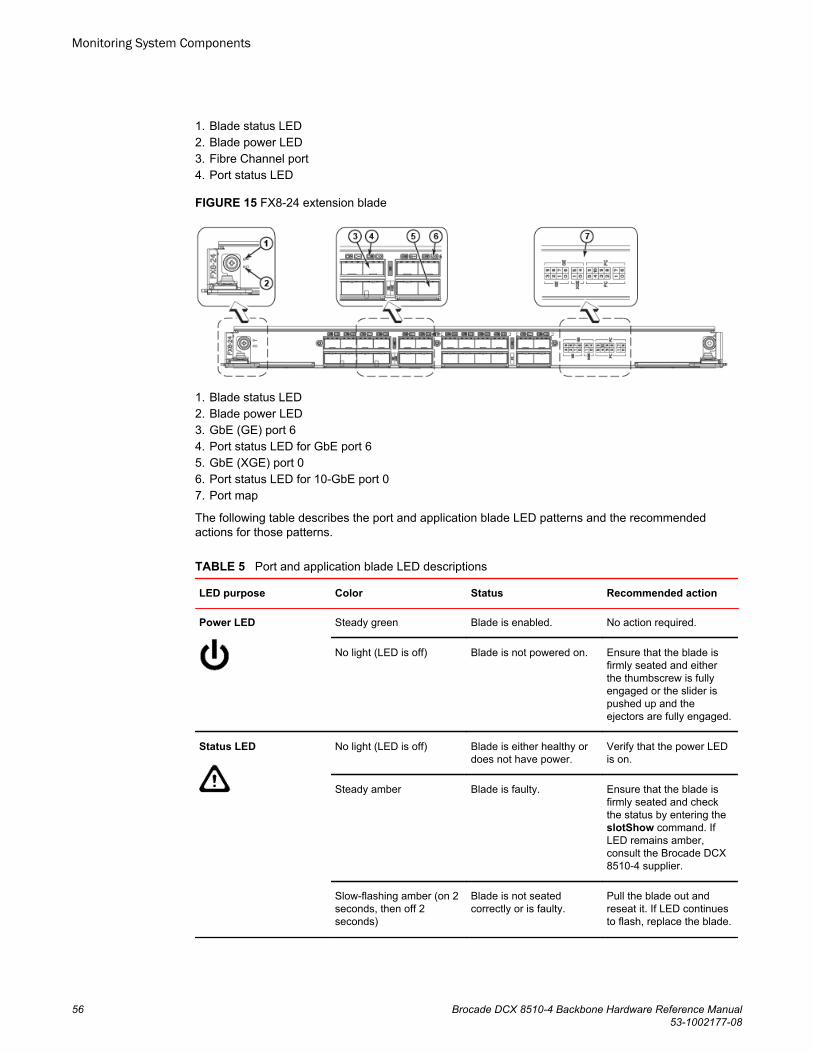
1. Blade status LED2. Blade power LED3. Fibre Channel port4. Port status LED
FIGURE 15 FX8-24 extension blade
1. Blade status LED2. Blade power LED3. GbE (GE) port 64. Port status LED for GbE port 65. GbE (XGE) port 06. Port status LED for 10-GbE port 07. Port map
The following table describes the port and application blade LED patterns and the recommendedactions for those patterns.
Port and application blade LED descriptions TABLE 5
LED purpose Color Status Recommended action
Power LED Steady green Blade is enabled. No action required.
No light (LED is off) Blade is not powered on. Ensure that the blade isfirmly seated and eitherthe thumbscrew is fullyengaged or the slider ispushed up and theejectors are fully engaged.
Status LED No light (LED is off) Blade is either healthy ordoes not have power.
Verify that the power LEDis on.
Steady amber Blade is faulty. Ensure that the blade isfirmly seated and checkthe status by entering theslotShow command. IfLED remains amber,consult the Brocade DCX8510-4 supplier.
Slow-flashing amber (on 2seconds, then off 2seconds)
Blade is not seatedcorrectly or is faulty.
Pull the blade out andreseat it. If LED continuesto flash, replace the blade.
Monitoring System Components
56 Brocade DCX 8510-4 Backbone Hardware Reference Manual53-1002177-08

Port and application blade LED descriptions (Continued)TABLE 5
LED purpose Color Status Recommended action
Fast-flashing amber (on1/2 second, then off 1/2second)
Environmental rangeexceeded.
Check for out-of-boundsenvironmental conditionand correct it.
FC Port Status No light (LED is off) Port has no incomingpower, or there is no lightor signal carrier detected.
Verify that the power LEDis on, check thetransceiver and cable.
Polling is in progress. Allow 60 seconds forpolling to complete.
Connected device isconfigured in an offlinestate.
Verify the status of theconnected device.
Steady green Port is online (connectedto an external device) buthas no traffic.
No action required.
Slow-flashing green (on 1second, then off 1 second)
Port is online butsegmented, indicating aloopback plug or cable oran incompatible switch.
Verify that the correctdevice is attached to theBrocade DCX 8510-4.
Fast-flashing green (on 1/4second, then off 1/4second)
Port is in internal loopback(diagnostic).
No action required.
Flickering green Port is online, with trafficflowing through port.
No action required.
Steady amber Port is receiving light orsignal carrier, but it is notonline yet.
Reset the port from theworkstation using theportEnable orportCfgPersistentEnablecommand.
Slow-flashing amber (on 2seconds, then off 2seconds)
Port is disabled due todiagnostic tests orportDisable orportCfgPersistentEnablecommand.
Reset the port from theworkstation using theportEnable orportCfgPersistentEnablecommand.
Fast-flashing amber (on1/2 second, then off 1/2second)
Transceiver or port isfaulty.
Change the transceiver orreset the switch from theworkstation.
Alternating green/amber Port is bypassed. Reset the port from theworkstation using theportEnable orportCfgPersistentEnablecommand.
GbE Port Status (FX8-24)- both 1-GbE and 10-GbEports
No light (LED is off) Port has no incomingpower, or there is no lightor signal carrier detected.
Verify that the power LEDis on, check thetransceiver and cable.
Monitoring System Components
Brocade DCX 8510-4 Backbone Hardware Reference Manual 5753-1002177-08

Port and application blade LED descriptions (Continued)TABLE 5
LED purpose Color Status Recommended action
Steady green Port is online but has notraffic.
No action required.
Slow-flashing green (on 1second, then off 1 second)
Beacon. Used to identifyspecific ports.
No action required.
Flickering green Port is online, with trafficflowing through port.
No action required.
Fast-flashing amber (on1/4 second, then off 1/4second)
Transceiver or port isfaulty.
Change the transceiver orreset the switch from theworkstation.
Determining the status of a control processor blade (CP8)
Complete the following steps to determine the status of a control processor blade (CP8)
1. Check the LED indicators on the CP blade. The LED patterns may temporarily change during POSTand other diagnostic tests. For information about how to interpret the LED patterns, refer to thefollowing table.
2. Check the port blade status by entering slotShow and haShow.
FIGURE 16 Control processor blade (CP8)
1. Power LED2. Status LED3. USB LED4. USB port5. Console port (Serial)6. Ethernet port (Mgmt IP)7. Ethernet port (Service IP)8. Active CP LED
Determining the status of a control processor blade (CP8)
58 Brocade DCX 8510-4 Backbone Hardware Reference Manual53-1002177-08

The following table describes the CP blade LED patterns and the recommended actions for thosepatterns.
CP blade LED descriptions TABLE 6
LED purpose Color Status Recommended action
Power Steady green CP blade is on. No action required.
No light (LED is off) CP blade is not on. Ensure that the blade is firmlyseated and has power.
Status No light (LED is off) CP blade is either healthy ordoes not have power.
Verify that the power LED is on.
Steady amber CP blade is faulty or the switchis still booting.
Ensure that the blade is firmlyseated and the switch hascompleted booting. If LED remainsamber, consult the Brocade DCX8510-4 supplier.
Slow-flashing amber(on 2 seconds, thenoff 2 seconds)
CP blade is not seatedcorrectly or is faulty.
Pull the blade out and reseat it. Ifthe LED continues to flash, replacethe blade.
Fast-flashing amber(on 1/2 second, thenoff 1/2 second)
Environmental rangeexceeded.
Check for out-of-boundsenvironmental condition and correctit.
Ethernet LinkStatus
No light (LED is off) Either an Ethernet link is notdetected, or it does not haveincoming power.
Ensure that the blade has power,the Ethernet cable is firmly seated,and the connected device isfunctioning.
Flickering green/amber
Ethernet link is healthy andtraffic is flowing through port.
No action required.
Ethernet LinkSpeed
No light (LED is off) Ethernet link speed is 10 Mb/sor CP blade does not haveincoming power.
Ensure that the CP has power.
NOTE: To force a persistentEthernet link speed, enter theifModeSet command.
Steady green Ethernet link speed is100/1000 Mb/s.
No action required.
USB Status Lamp on USB stick enabled. No action required.
Lamp off USB stick not present ordisabled.
No action required.
Active CP Steady blue Active CP blade. No action required.
No light (LED is off) Standby CP blade. No action required.
Monitoring System Components
Brocade DCX 8510-4 Backbone Hardware Reference Manual 5953-1002177-08

Determining the status of a core switch blade (CR16-4)
Complete the following steps to determine the status of a core switch blade (CR16-4).
1. Check the LED indicators on the core switch blade. The LED patterns may temporarily changeduring POST and other diagnostic tests. For information about how to interpret the LED patterns,refer to the following table.
2. Check the core switch blade status by entering slotShow and haShow.
FIGURE 17 Core switch blade (CR16-4)
1. Power LED2. Status LED3. QSFP port map and trunking diagram4. QSFP connectors
The following table describes the core switch blade LED patterns and the recommended actions forthose patterns.
CR blade LED descriptions TABLE 7
LED purpose Color Status Recommended action
Power Steady green CR16-4 blade is on. No action required.
No light (LED isoff)
CR16-4 blade is not on. Ensure that the blade is firmlyseated and has power.
Status No light (LED isoff)
CR16-4 blade is either healthyor does not have power.
Verify that the power LED is on.
Steady amber CR16-4 blade is faulty or theswitch is still booting.
Ensure that the blade is firmlyseated and the switch hascompleted booting. If the LEDremains amber, consult the BrocadeDCX 8510-4 supplier.
Slow-flashingamber (on 2seconds, then off2 seconds)
CR16-4 blade is not seatedcorrectly or is faulty.
Pull the blade out and reseat it. Ifthe LED continues to flash, replacethe blade.
Fast-flashingamber (on 1/2second, then off1/2 second)
Environmental rangeexceeded.
Check for out-of-boundsenvironmental condition and correctit.
Determining the status of a core switch blade (CR16-4)
60 Brocade DCX 8510-4 Backbone Hardware Reference Manual53-1002177-08

CR blade LED descriptions (Continued)TABLE 7
LED purpose Color Status Recommended action
QSFP connectorstatus LED
No light (LED isoff)
No QSFP module, all fourQSFP ports are disabled
No action needed if the QSFP is notinstalled or verify that the QSFP isfully inserted.
Steady amber QSFP module is in, all fourports have no signal/no sync.
Ensure that the cable is properlyconnected. If the LED remainsamber, consult the Brocade DCX8510-4 supplier.
Blinking amber Port is disabled or faulted, FClink activity, segmented,loopback mode, also duringtransition between cable plugin and all four ports online.
Check for console messages or waitfor all four ports to come online.
Steady green QSFP module is in and allports are online.
No action needed.
Refer to the Port numbering on page 27 section for a map of the ports and a table of external ports tointernal ports as shown in the slotShow command.
Determining the status of a power supply
Complete the following steps to determine the status of a power supply.
1. Check the LED indicator on the power supply. The LED patterns may temporarily change duringPOST and other diagnostic tests; for information about how to interpret the LED patterns, refer to thefollowing table. The Brocade DCX 8510-4 has two power supplies. Be sure to check each module.
2. Check the power supply status by entering psShow.
The power supply status displays OK, Absent, or Faulty. If a power supply displays absent or faulty,contact the Brocade DCX 8510-4 supplier to order replacement parts. Both physically absent orfaulty could also be the result of the power supply not being properly seated or being turned off.
FIGURE 18 Power supply
1. Power LED
The following table describes the power supply LED patterns and the recommended actions for thosepatterns.
Determining the status of a power supply
Brocade DCX 8510-4 Backbone Hardware Reference Manual 6153-1002177-08

Power supply LED descriptions TABLE 8
LED purpose Color Status Recommended action
Power No light (LED isoff)
Power supply does not haveincoming power and is notproviding power to the BrocadeDCX 8510-4.
Ensure that the power supply is firmlyseated, the Brocade DCX 8510-4 hasincoming power, both power cablesare connected, and AC powerswitches are on.
Steady green Power supply has incomingpower and is providing power tothe Brocade DCX 8510-4.
No action required.
Flashing green Power supply is about to fail. Replace the power supply.
Determining the status of a blower assembly
Complete the following steps to determine the status of a blower assembly.
1. Check the LED indicators on the blower assembly. The LED patterns may temporarily changeduring POST and other diagnostic tests; for information about how to interpret the LED patterns,refer to the following table. The Brocade DCX 8510-4 has two blowers. Be sure to check eachmodule.
2. Check the blower assembly status using the fanShow command.
The status for each blower assembly displays OK, Absent, or Faulty. The RPM of each fan in theassembly is also provided. If a blower assembly displays absent or faulty, contact the Brocade DCX8510-4 supplier to order replacement parts. Both physically absent or faulty could also be the resultof the power supply not being properly seated.
FIGURE 19 Blower assembly
1. Power LED2. Fault LED
The following table describes the LED patterns for the blower assembly.
Determining the status of a blower assembly
62 Brocade DCX 8510-4 Backbone Hardware Reference Manual53-1002177-08

Blower assembly LED descriptions TABLE 9
LED purpose Color Status Recommended action
Power No light (LED is off) Blower assembly does nothave power.
Ensure that the blower assembly isfirmly seated and has power.
Steady green Blower assembly has power. No action required.
Fault No light (LED is off) Blower assembly is eitherhealthy or does not havepower.
Ensure that the blower assembly haspower.
Steady amber Blower assembly has afailure (full or partial).
Replace the blower assembly.
Slow-flashing amber (on2 seconds, then off 2seconds)
Blower assembly is notseated correctly or is faulty.
Pull the unit out and reseat it. If theLED continues to flash, replace theunit.
Flashing amber (on 1/2second, then off 3.5seconds)
Fan is disabled. Run the fanEnable command toenable the fan.
Fast-flashing amber(on1/2 second, then off 1/2second)
Environmental rangeexceeded.
Check for out-of-boundsenvironmental condition, resolve anyproblems, and reseat the unit. If theLED continues to flash, replace theunit.
Determining the status of a WWN cardComplete the following steps to determine the status of a WWN card.
NOTEThe WWN bezel (logo plate) covers the WWN cards. The LEDs on the WWN cards are not visibleunless the bezel is removed.
Enter the chassisShow command to display information about the WWN card. (WWN units correspondto information specific to the WWN card.) Error messages that may indicate problems with a WWN cardare summarized in the following table.
Messages that may indicate WWN card failure TABLE 10
Type of message Sample error message
WWN unit fails its field-replaceable unit(FRU) header access.
0x24c (fabos): Switch: switchname, error EM-I2C_TIMEOUT, 2, WWN 1 I2C timed out: state 0x4
WWN unit fails to power on. <timestamp>, [EM-1004], <sequence-number>,, CRITICAL, <system-name>, WWN # failed to power onor<timestamp>, [EM-1043], <sequence-number>,, WARNING, <system-name>, Can't power <FRU Id> <state (on or off)>.
Determining the status of a WWN card
Brocade DCX 8510-4 Backbone Hardware Reference Manual 6353-1002177-08

Messages that may indicate WWN card failure (Continued)TABLE 10
Type of message Sample error message
WWN unit is being faulted. 0x24c (fabos): Switch: switchname, Critical EM-WWN_UNKNOWN, 1, Unknown WWN #2 is being faultedor<timestamp>, [EM-1003], 40, SLOT 7 | FFDC | CHASSIS, CRITICAL, Brocade_DCX, WWN 2 has unknown hardware identifier: FRU faultedor<timestamp>, [EM-1034], <sequence-number>,, ERROR, <system-name>, WWN # set to faulty, rc=<return code>
WWN unit is not present or is notaccessible.
0x24c (fabos): Switch: switchname, Error EM-WWN_ABSENT, 2, WWN #1 not presentor<timestamp>, [EM-1036], <sequence-number>,, WARNING, <system-name>, <FRU Id> is not accessible.
Writing to the FRU history log(hilSetFruHistory) has failed.
0x24c (fabos): Switch: switchname, Error EM-HIL_FAIL, 2, HIL Error: hilSetFruHistory failed, rc=-3 for SLOT 3
WWN unit insertion was detected. <timestamp>, [EM-1049], <sequence-number>,, INFO, <system-name>, FRU WWN # insertion detected.
WWN unit removal was detected. <timestamp>, [EM-1050], <sequence-number>,, INFO, <system-name>, FRU WWN # removal detected.
The following figure displays the WWN bezel (logo plate). The WWN cards are under the bezel.
FIGURE 20 WWN bezel (logo plate) for DCX-4S and DCX 8510-4
Monitoring System Components
64 Brocade DCX 8510-4 Backbone Hardware Reference Manual53-1002177-08

Removal and Replacement Procedures
● Introduction..................................................................................................................... 65● ESD precautions............................................................................................................. 65● Chassis door removal and replacement..........................................................................66● Vertical cable management fingers removal and replacement....................................... 67● Port, application, and encryption blade removal and replacement................................. 68● Blade filler panel removal and replacement.................................................................... 72● Control processor blade (CP8) removal and replacement.............................................. 73● Core switch blade (CR16-4) removal and replacement.................................................. 81● Power supply removal and replacement......................................................................... 84● Blower assembly removal and replacement................................................................... 86● WWN card removal and replacement............................................................................. 87● Transceiver removal and replacement............................................................................91● Inter-chassis link (ICL) cable removal and replacement................................................. 96● Brocade DCX 8510-4 chassis removal and replacement............................................. 101
Introduction
NOTERead the safety notices before servicing (Caution and Danger Notices on page 147).
The field-replaceable units (FRUs) in the Brocade DCX 8510-4 can be removed and replaced withoutspecial tools. The Brocade DCX 8510-4 can continue operating during many of the FRU replacements ifthe conditions specified in the procedures are followed.
The following sections contain FRU removal and replacement procedures (RRPs).
ESD precautionsThe Brocade DCX 8510-4 contains ESD-sensitive FRUs. When working with any Brocade DCX 8510-4FRU, use correct electrostatic discharge (ESD) procedures.
• Wear a wrist grounding strap connected to chassis ground (if the Brocade DCX 8510-4 is plugged in)or a bench ground.
DANGERFor safety reasons, the ESD wrist strap should contain a series 1 megaohm resistor.
• Store all ESD-sensitive components in antistatic packaging.
CAUTIONStatic electricity can damage the chassis and other electronic devices. To avoid damage, keepstatic-sensitive devices in their static-protective packages until you are ready to install them.
Brocade DCX 8510-4 Backbone Hardware Reference Manual 6553-1002177-08

Chassis door removal and replacement
NOTEThe chassis door must be installed to ensure the Brocade DCX 8510-4 meets EMI and otherregulatory certifications.
Time and items requiredThe replacement procedure for the chassis door takes less than five minutes.
Removing a chassis doorSupport the door to prevent it from falling. Pull and remove the door. It will pop off the ball studs.
FIGURE 21 Removal and replacement of the chassis door
Replacing a chassis doorComplete the following steps to reinstall the door.
1. Align the holes in the door with the ball studs on the chassis.2. Push the door into place. It will snap onto the studs.
Chassis door removal and replacement
66 Brocade DCX 8510-4 Backbone Hardware Reference Manual53-1002177-08

Vertical cable management fingers removal and replacementThe Brocade DCX 8510-4 comes equipped with two vertical cable management finger assemblies. Itcan continue to operate during the replacement of the cable management fingers. Due to the horizontalorientation of the blades in the Brocade DCX 8510-4, the finger assemblies are attached to the uprightsof the mounting rack.
Time and items requiredThe replacement procedure for the cable management fingers takes less than five minutes. A #1Phillips screwdriver is required.
Removing a cable management finger assemblyComplete the following steps to remove the cable management finger assembly.
1. Remove the chassis door.2. Remove the cables from the cable management finger assembly and rearrange the cables around
the assembly.3. Unscrew and save the three (3) screws holding the finger assembly to the rack upright. Support the
assembly to prevent it from falling.4. Remove the cable management finger assembly.5. If necessary, repeat steps 1 through 4 for the other finger assembly.
Vertical cable management fingers removal and replacement
Brocade DCX 8510-4 Backbone Hardware Reference Manual 6753-1002177-08

FIGURE 22 Removal and replacement of the vertical cable management finger assemblies
Replacing a cable management finger assemblyComplete the following steps to replace the cable management finger assembly.
1. Position and tighten the three (3) screws to secure the vertical cable management finger assemblyto the rack upright.
2. Arrange the cables along the cable management finger assembly.3. If necessary, repeat steps 1 and 2 for the other cable management finger assembly.4. Replace the chassis door.
Port, application, and encryption blade removal and replacementThis document describes how to remove and replace port, application, and encryption blades. It doesnot cover the core (CR) blades or the control processor (CP) blades.
CAUTIONIf you do not install a module or a power supply in a slot, you must keep the slot filler panel inplace. If you run the chassis with an uncovered slot, the system will overheat.
Slots are numbered from 1 through 8, from bottom to top when facing the port side of the BrocadeDCX 8510-4. Port, application, and encryption blades can be installed in slots 1-2 and 7-8.
Replacing a cable management finger assembly
68 Brocade DCX 8510-4 Backbone Hardware Reference Manual53-1002177-08

This section is applicable for all the following port, application, and encryption blades supported on theDCX 8510 chassis:
Blade DCX DCX-4S DCX 8510-4 DCX 8510-8
FC8-32E port blade No No Supported Supported
FC8-48E port blade No No Supported Supported
FC8-64 port blade Supported Supported Supported Supported
FC16-32 port blade No No Supported Supported
FC16-48 port blade No No Supported Supported
FC16-64 port blade No No Supported Supported
FCOE10-24 applicationblade
Supported Supported No Supported (only onslot 1)
NOTECannot be in the same chassis with FC8-48E, FC8-64, FC16-48, FC16-64, FS8-18, orFX8-24.
FS8-18 encryption blade Supported Supported Supported Supported
FX8-24 application blade Supported Supported Supported Supported
Time and items requiredThe replacement procedure for each blade takes less than 10 minutes. Removing and restoringtransceivers and cables may take longer depending on how many must be changed. The followingitems are required for the blade and filler panel replacement:
• Electrostatic discharge (ESD) grounding strap• Workstation computer• Replacement blade or filler panel• #2 Phillips screwdriver• Small form-factor pluggable (SFP+, mSFP, or QSFP) transceivers (as needed)• Optical and copper cables (as needed)
NOTEFor information about the transceivers that are qualified for the Brocade chassis, refer to Transceiverremoval and replacement on page 91.
Removing a bladeComplete the following steps to remove a blade.
Time and items required
Brocade DCX 8510-4 Backbone Hardware Reference Manual 6953-1002177-08

Follow electrostatic discharge (ESD) precautions when removing a blade. Wear a wrist groundingstrap connected to chassis ground (if the Brocade DCX 8510-4 is plugged in) or a bench ground.
DANGERFor safety reasons, the ESD wrist strap should contain a series 1 megaohm resistor.
NOTEBefore removing any cables from a blade, note the cable order (identify each cable by its physicalport). It is a good practice to keep a table of cable to port mapping.
NOTE
If multiple blades are being replaced, replace one blade at a time.
1. Remove the chassis door.2. Check the power LED, status LED, and port status LED to identify any possible problems. A failed
port or application blade can be identified by inspecting the LEDs on the front panel of each blade.3. Establish a Telnet or console session.
Before replacing a blade, establish a Telnet or console connection to determine a failure and verifyoperation after replacement. Use the switchShow command to view the status of the blades.
4. Check for adequate cable slack. Ensure there is plenty of cable slack to remove a blade withoutcable obstruction.
5. Ensure that the part number on the unit being replaced matches the replacement part number. ThechassisShow command displays information about the blades, including part numbers (xx-xxxxxxx-xx), serial numbers, and additional status.
6. Ensure that traffic is not flowing through the blade (port status LED should be off) prior todisconnecting cables.
7. Ensure that traffic is not flowing through the blade.8. Disconnect all cables and transceivers from the blade. For mSFP transceivers (FC8-64 only), it is
recommended that you use the pull tab to remove the transceiver from the blade.9. Unscrew the two thumbscrews from the ejectors on the blade using the Phillips screwdriver.
Unscrew the left thumbscrew until it pops out. This initiates a hot-swap request.10.Wait for the power LED to turn off in response to the hot-swap request before removing the blade.11.Open the ejectors by rotating them toward the center of the blade face. Pull the blade out of the
chassis using the ejectors.12.If the blade is not being replaced by another blade, install a filler panel.
Removal and Replacement Procedures
70 Brocade DCX 8510-4 Backbone Hardware Reference Manual53-1002177-08

FIGURE 23 Removal and replacement of the port, application, and encryption blades (FC16-48 portblade shown)
Replacing a bladeComplete this procedure to replace a blade.
Follow electrostatic discharge (ESD) precautions when replacing a blade. Wear a wrist grounding strapconnected to chassis ground (if the Brocade DCX 8510-4 is plugged in) or a bench ground.
DANGERFor safety reasons, the ESD wrist strap should contain a series 1 megaohm resistor.
NOTEAn FA4-18i application blade and the Brocade DCX 8510-4 must have the same version of firmware. Toupgrade firmware versions, refer to the Fabric OS Administrator's Guide.
1. Orient the blade so that the ports are at the front of the chassis and the flat side of the blade is on thebottom.
2. Open the ejectors by rotating them toward the center of the blade face, align the flat side of the bladeinside the left and right rail guides in the slot, and slide the blade into the slot until it is firmly seated.
3. Close the ejectors by rotating them away from the center of the blade. The levering action of theejectors seats the blade in the slot.
4. Tighten the thumbscrews using the Phillips screwdriver.5. Verify that the power LED on the port blade is displaying a steady green light. If it does not turn on,
ensure that the blade is firmly seated.
Replacing a blade
Brocade DCX 8510-4 Backbone Hardware Reference Manual 7153-1002177-08

6. Verify that the Status LED on the blade shows amber until POST completes for the blade. It shouldthen display green. If it remains amber, the board may not be properly seated in the backplane orthe board may be faulty.
7. Install the transceivers and cables in the blade. For mSFP (FC8-64 port blade only) and QSFP(FC16-64 port blade only) transceivers, it is recommended that you install the cables in thetransceivers before installing the transceivers in the blade.
8. Group and route the cables through the vertical cable management finger assemblies.9. Replace the chassis door.
Blade filler panel removal and replacementThis section describes how to remove and replace blade filler panels.
NOTESome filler panels have two thumbscrews and some have only one. Be sure to unscrew or tighten bothif you are using the two-screw version.
Removing a filler panelComplete the following steps to remove a filler panel from the chassis.
CAUTIONIf you do not install a module or a power supply in a slot, you must keep the slot filler panel inplace. If you run the chassis with an uncovered slot, the system will overheat.
1. Remove the chassis door.2. Unscrew the thumbscrews on the panel using the Phillips screwdriver.3. Using the tabs, pull the filler panel out of the chassis.
Blade filler panel removal and replacement
72 Brocade DCX 8510-4 Backbone Hardware Reference Manual53-1002177-08

FIGURE 24 Removal and replacement of the blade filler panel
Replacing a filler panelDo not leave a slot empty. This will adversely affect cooling of the chassis.
1. Orient the filler panel.2. Slide the filler panel into the slot until it is firmly seated.3. Tighten the thumbscrews.4. Replace the chassis door.
Control processor blade (CP8) removal and replacementThis document describes how to remove and replace a control processor (CP8) blade. Each chassishas two CP8 blades. In the DCX 8510-4, they are located in slots 4 and 5.
NOTEThe CP8 blade is compatible only with the Brocade DCX Backbones (including the DCX 8510Backbones).
NOTE
The Brocade’s firmware upgrade policy for CP8 blades specifies testing for the current Fabric OSrelease and one version earlier. It is possible to upgrade by more than one version, but it is a very
Replacing a filler panel
Brocade DCX 8510-4 Backbone Hardware Reference Manual 7353-1002177-08
specific and detailed process. Read the directions under Downloading firmware from an FTP server onpage 78 or Downloading firmware from a USB device on page 79 carefully.
NOTE
If the new CP blade does not have the same firmware as the active CP blade, the new blade must beupgraded to the same firmware version. You can determine the firmware version on the replacementblade and perform a firmware upgrade if necessary after inserting the blade in the chassis, but youmust disable high availability (HA) before inserting the new blade. If the new CP blade is severelydown-level, a very specific procedure must be followed to bring the blade up to the correct firmwareversion.
Time and items requiredThe replacement procedure for the CP blade takes approximately 30 minutes. The following items arerequired for the CP blade replacement:
• Electrostatic discharge (ESD) grounding strap• Workstation computer• Serial cable• IP address of an FTP server for backing up the Brocade DCX 8510-4 configuration• #2 Phillips screwdriver• Replacement Brocade DCX 8510-4 control processor blade (CP8)
If you are upgrading through multiple versions of the Fabric OS, consult the Steps for upgradingthrough multiple versions of Fabric OS table to see which intermediate versions of the Fabric OS youmight need. Plan carefully and for extra time if this is your situation.
Faulty CP blade indicatorsConfirm that you need to replace the CP blade. The following events may indicate that a CP blade isfaulty:
• The status LED on the CP blade is lit steady amber, or the power LED is not lit.• The CP blade does not respond to Telnet commands, or the serial console is not available.• The slotShow command does not show that the CP blade is enabled.• The haShow command indicates an error.• The clock is inaccurate, or the CP blade does not boot up or shut down normally.• Any of the following messages display in the error log:
‐ "Slot unknown" message relating to a CP slot‐ CP blade errors or I2C timeouts‐ FRU: FRU_FAULTY messages for a CP blade‐ Configuration loader messages or "Sys PCI config" messages‐ Generic system driver messages ("FABSYS")‐ Platform system driver messages ("Platform")‐ EM messages that indicate a problem with a CP blade‐ Function fail messages for the CP master
For more information about error messages, refer to the Fabric OS Message Reference.
Time and items required
74 Brocade DCX 8510-4 Backbone Hardware Reference Manual53-1002177-08
Recording critical Brocade DCX 8510-4 informationBack up the backbone configuration before you replace a CP blade. Refer to the Fabric OSAdministrator's Guide for backup information.
NOTE
The following instructions reference specific slot numbers. These numbers will be different between theDCX 8510-8/DCX and the DCX 8510-4/DCX-4S chassis.
1. Connect to the chassis and log in as admin, using a serial console connection.2. Enter haShow to determine which CP blade is active. The following example is from a DCX chassis.
DCX_124:admin> haShowLocal CP (Slot 7, CP1) : ActiveRemote CP (Slot 6, CP0) : Standby, HealthyHA Enabled, Heartbeat Up, HA State Synchronized
3. Enter all remaining commands from the serial console for the active CP blade, unless otherwiseindicated. For more information about commands, refer to the Fabric OS Command Reference
4. If the active CP blade is faulted, automatic fail over to the standby CP blade should have occurred.Confirm that the standby CP blade is active and power off the faulted CP blade, log in to the standbyCP blade, and skip to step 7.
If automatic failover has not occurred, manually fail over the faulty blade by moving the slider to theoff position (to the right in a DCX 8510-4). Then power off the faulted blade, log in to the standby CPblade, and skip to step 7.
5. If both CP blades are healthy and you want to replace the standby CP blade, log in to the active CPblade and skip to step 7.
6. If both CP blades are healthy and you want to replace the active CP blade, log in to the active CPblade and run the following steps:a) Run the haFailover command to make the standby CP blade the active blade. The currently
active CP blade becomes the standby blade. Wait until the status LED on the currentlyactive CP blade is no longer lit.
b) Confirm the completion of the failover by running the haShow command.c) Log in to the new active CP blade.
7. Run firmwareShow to note the firmware version of the active CP blade.
The following example shows the results of the firmwareshow command when the firmwareversions on the two CP blades are not the same. Note the warning message at the end of the output.
DCX_120:root> firmwareshowSlot Name Appl Primary/Secondary Versions Status-------------------------------------------------------------------------- 64 CP0 FOS v6.4.0a STANDBY v6.4.0a 75 CP1 FOS v7.0.0 ACTIVE * v7.0.0WARNING: The local CP and remote CP have different versionsof firmware, please retry firmwaredownload command.DCX_120:root>
8. Run haDisable from the active CP blade to prevent failover or communication between the CPblades during the replacement.
9. Use the configUpload command to upload the backbone configuration to a specified FTP server.Enter information at the prompts.
Recording critical Brocade DCX 8510-4 information
Brocade DCX 8510-4 Backbone Hardware Reference Manual 7553-1002177-08

a) Run the fosconfig --show command to determine if virtual fabrics are enabled. If so, runthe configupload -vf command. This command uploads the Brocade DCX 8510-4 virtualfabric data.
b) If virtual fabrics are not enabled, run the configupload command. This command uploadsthe Brocade DCX 8510-4 configuration.
Removing a control processor blade (CP8)The chassis continues to operate while a CP blade is being replaced if the redundant CP blade isactive and a failover does not occur. You can prevent failover by entering the haDisable command.
Complete the following steps to remove a CP8 control blade.
1. Remove the chassis door.2. Log in to the active CP as the admin user. You can use a serial cable or Telnet, Web Tools, or
Fabric Manager. Determine which CP is active using the haShow command or view the active LEDon the front of the CP.
3. If the faulty CP is the active CP, issue the haFailover command. Wait until the failover hascompleted. Use the haShow command to verify the CPs are synchronized and the failover iscomplete.
Depending on the nature of the CP failure, it is possible that the haFailover command may notwork. Proceed to the next step anyway.
4. Enter the haDisable command. This is required before physically removing and replacing a CPblade.
5. Power off the blade by sliding the slider switch in the left ejector to the right to the off position. Donot eject the blade until the power LED is off and you have completed the next two steps.
6. Disconnect all cables from the faulty (standby) CP.7. Unscrew the thumbscrew from both ejectors using the Phillips screwdriver.8. Lever open both ejector handles simultaneously to approximately 45 degrees and pull the CP blade
out of the chassis.
Removing a control processor blade (CP8)
76 Brocade DCX 8510-4 Backbone Hardware Reference Manual53-1002177-08

FIGURE 25 Removal and replacement of the control processor blade (CP8)
Replacing a control processor blade (CP8)
NOTE
Read ALL of the instructions for replacing the CP blade before beginning the procedure. Use the sameversion of Fabric OS on both CP blades. Using different versions is not supported and may causemalfunctioning. If the replacement CP blade has a different version of Fabric OS, bring both blades tothe same firmware version. Once you have installed the replacement CP blade, determine the versionof firmware on the replacement CP blade and upgrade it if necessary.
Complete the following steps to remove a CP8 control blade.
1. Open the ejector handles to approximately 45 degrees. Orient the CP blade so that the handles aretoward you and the flat metal side should be facing down.
2. Align the flat metal side of the CP blade inside the left and right blade guides in the slot. Slide the CPblade into the slot until it is firmly seated.
3. Tighten the thumbscrew inside each handle using the Phillips screwdriver.4. Turn the CP blade on by sliding the ON/OFF switch in the left handle to the left, to cover the
thumbscrew.5. Verify that the power LED is green. If not, ensure that the CP blade has power and is firmly seated
and that the ejectors are in the locked position.6. Connect the cables to the new CP blade.7. Remain logged in to the active CP and continue to Verifying operation of the new CP blade on page
78.
Replacing a control processor blade (CP8)
Brocade DCX 8510-4 Backbone Hardware Reference Manual 7753-1002177-08

Verifying operation of the new CP bladeTo verify that boot and POST are complete on the new CP blade and that the CP blade has achievedfailover redundancy, perform the following steps.
1. Enter slotShow . The command output shows the new CP blade as "enabled."
If the standby CP is unresponsive, you can try unplugging the new CP blade, running haDisable onthe active CP blade, and plugging the new CP blade back in. At that point, you can repeat step 1 tobegin the verification process again.
2. Determine the version by entering firmwareShow . If the serial console on the replacement CPblade is connected, issue the firmwareShow command there. More information is available throughthe console.
NOTEThe DCX 8510-4 requires Fabric OS 7.0.0 or later to be recognized. If the firmware on thereplacement blade is earlier than 7.0.0 it must be brought up to the version on the active CP blade,which must be at least 7.0.0.
3. If the firmware versions for both CP blades are the same, skip to Completing the replacement onpage 81.
If the firmware version on the replacement blade does not match that on the active CP blade, awarning message appears with the results of the firmwareshow command. The results of thefirmwareshow command may look similar to the following. Note the warning message at the end ofthe output.
DCX_xyz:admin> firmwareshowSlot Name Appl Primary/Secondary Versions Status------------------------------------------------------------------------ 64 CP0 FOS v7.0.0 ACTIVE v7.0.0 75 CP1 FOS v6.3.0a STANDBY * v6.3.0a * Local CPWARNING: The local CP and remote CP have different versionsof firmware, please retry firmwaredownload command.
4. You must bring the replacement blade to the same firmware level as the active blade by running thefirmwareDownload -s command directly on the replacement blade to bring it up to the proper level.The firmwareshow command results show which slots hold the active and standby (replacement)CP blades.
If you are using an FTP server to download the firmware, skip to Downloading firmware from anFTP server on page 78.
If you are using a USB device to download the firmware, skip to Downloading firmware from a USBdevice on page 79. If the firmware on the standby CP blade is more than one level down from thelevel on the active CP blade, you must have formatted USB devices for each of the versions you willneed to upgrade.
For details on supported upgrade paths and steps to upgrade through multiple versions of FabricOS, refer to the Fabric OS Release Notes, and the Fabric OS Upgrade Guide.
Downloading firmware from an FTP server
For this task, determine the correct sequence of upgrading firmware versions to reach your targetversion.
Complete the following steps to download the firmware from an FTP server.
Verifying operation of the new CP blade
78 Brocade DCX 8510-4 Backbone Hardware Reference Manual53-1002177-08

1. Log in to the standby CP blade as admin. If you need to know the IP address of the standby blade,run ipaddrshow.
You should remain logged in to the active CP blade in order to monitor it.2. Run firmwareDownload -s to download the firmware to the standby CP blade. The -s option also
disables the autoreboot, so you will have to manually issue a reboot after the download finishes toinitiate firmwarecommit. Enter all requested information (use default values).
3. When the download process finishes, run firmwareDownloadStatus to verify that the firmware hasbeen updated. The command displays a running account of the progress of the firmwareDownloadcommand (if it is still running) until the command has completed. The final message is similar to thefollowing and will appear with a date and time stamp:
Slot 4 (CP0, active): Firmwaredownload command has completed successfully. Use firmwareshow to verify the firmware versions.
4. On the standby CP blade (the blade for which you just changed the firmware level), run reboot. Thereboot of the standby CP will initiate a firmwarecommit to the secondary partition and log you out.
DCX_124:admin> rebootBroadcast message from root (ttyS0) Fri Jun 18 14:49:45 2010...The system is going down for reboot NOW !!INIT: Switching to runlevel: 6INIT: Sending processes the TERM signal DCX_124:admin> HAMu Heartbeat down, stop FSSUnmounting all f##exiting due to signal: 9, pending signals: 0x20000, 0x0ilesystems.Please stand by while rebooting the system...Restarting system.The system is coming up, please wait......Fri Jun 18 14:53:13 2010: Doing firmwarecommit now.Please wait ...Fri Jun 18 14:55:27 2010: Firmware commit completes successfully.Validating the filesystem ...Fri Jun 18 22:36:05 2010: Doing firmwarecommit now.Please wait ...Fri Jun 18 22:36:48 2010: Firmware commit completes successfully.2010/06/18-14:56:50, [SULB-1004], 908, SLOT 7 | CHASSIS, INFO, Brocade_DCX, Firmwarecommit has completed.2010/06/18-14:56:50, [SULB-1036], 909, SLOT 7 | CHASSIS, INFO, Brocade_DCX, The new Version: Fabric OS v6.3.0c2010/06/18-14:56:50, [SULB-1002], 910, SLOT 7 | CHASSIS, INFO, Brocade_DCX, Firmwaredownload command has completed successfully.
NOTEThe time stamp on the co-CPU may not be in sync with the main CPU on the blade. This is not acause for concern.
5. Log back in to the standby CP blade and run firmwareDownloadStatus on the standby CP blade tovalidate a successful commit. This may take 10 minutes.
6. If you are upgrading through several levels of the Fabric OS, repeat step 2 through step 5 as often asnecessary based on the path outlined in the preceding table . Otherwise, proceed to step 7.
7. Log out of the standby CP blade and log in to the active CP blade.8. Proceed to Completing the replacement on page 81.
Downloading firmware from a USB device
For this task, determine the correct sequence of upgrading firmware versions to reach your targetversion.
Complete the following steps to download the firmware from a USB device.
Downloading firmware from a USB device
Brocade DCX 8510-4 Backbone Hardware Reference Manual 7953-1002177-08

This section assumes that the new firmware has already been copied onto the USB device. The folderstructure on the USB device must be as follows in order to allow the device to be enabled:
• brocade>
‐ config‐ firmware‐ firmwareKey‐ support
The firmware folder contains the folder for the specific release you are installing.
1. Insert the USB device into the active CP blade.2. Attach a serial cable from the PC to the active CP blade.3. Log in to the active CP blade as admin if you are not still logged in and enter usbStorage -e to
enable the USB device.4. Remove the serial cable from the active CP blade and attach it to the standby CP blade and log in
as admin.5. Run firmwareDownload -s to download the firmware to the standby CP blade. The -s option also
disables the autoreboot, so you will have to manually issue a reboot after the download finishes toinitiate firmwarecommit. Enter all requested information (use default values).
6. When the download process finishes, run firmwareDownloadStatus to verify that the firmware hasbeen updated. The command displays a running account of the progress of the firmwareDownloadcommand until the command has completed. The final message is similar to the following and willappear with a date and time stamp:
Slot 4 (CP0, active): Firmwaredownload command has completed successfully. Use firmwareshow to verify the firmware versions.
7. Ensure that you are still logged in to the standby CP blade (the blade for which you just changedthe firmware level) and type reboot. The reboot of the standby CP will initiate a firmwarecommit tothe secondary partition and log you out.
DCX_124:admin> rebootBroadcast message from root (ttyS0) Fri Jun 18 14:49:45 2010...The system is going down for reboot NOW !!INIT: Switching to runlevel: 6INIT: Sending processes the TERM signal DCX_124:admin> HAMu Heartbeat down, stop FSSUnmounting all f##exiting due to signal: 9, pending signals: 0x20000, 0x0ilesystems.Please stand by while rebooting the system...Restarting system.The system is coming up, please wait......Fri Jun 18 14:53:13 2010: Doing firmwarecommit now.Please wait ...Fri Jun 18 14:55:27 2010: Firmware commit completes successfully.Validating the filesystem ...Fri Jun 18 22:36:05 2010: Doing firmwarecommit now.Please wait ...Fri Jun 18 22:36:48 2010: Firmware commit completes successfully.2010/06/18-14:56:50, [SULB-1004], 908, SLOT 7 | CHASSIS, INFO, Brocade_DCX, Firmwarecommit has completed.2010/06/18-14:56:50, [SULB-1036], 909, SLOT 7 | CHASSIS, INFO, Brocade_DCX, The new Version: Fabric OS v6.3.0c2010/06/18-14:56:50, [SULB-1002], 910, SLOT 7 | CHASSIS, INFO, Brocade_DCX, Firmwaredownload command has completed successfully.
NOTEThe time stamp on the co-CPU may not be in sync with the main CPU on the blade. This is not acause for concern.
Removal and Replacement Procedures
80 Brocade DCX 8510-4 Backbone Hardware Reference Manual53-1002177-08

8. Log back in to the standby CP blade and enter firmwareDownloadStatus on the standby CP bladeto validate a successful commit. This may take 10 minutes.
9. If you are upgrading through several levels of the Fabric OS, repeat step 5 through step 8 as often asnecessary based on the path outlined in the preceding table . Otherwise, proceed to step 10.
10.Log out of the standby CP blade and log in to the active CP blade.11.Proceed to Completing the replacement on page 81.
Completing the replacementComplete the following steps to complete the CP8 control blade replacement procedure.
1. Enter haEnable to re-enable HA on the active CP blade.
NOTEFor Fabric OS 7.0.0 and later, haEnable will cause the standby CP blade to reboot. Wait until POSTcompletes before moving to the next step. POST is complete when the Status LED on the CP bladereturns to a steady green state.
2. Enter haShow and verify that the command output includes "HA Enabled, Heartbeat Up". If it is notyet enabled, re-enter the command until you have verified that redundancy is achieved.
DCX_124:admin> hashowLocal CP (Slot 7, CP1) : ActiveRemote CP (Slot 6, CP0) : Standby, HealthyHA Enabled, Heartbeat Up, HA State Synchronized
3. EnterfirmwareShow to verify that the firmware version has been updated and that the versions arethe same on the two CP blades. The slot numbers will be different for the DCX 8510-4 or DCX-4S.(not all slot numbers are shown).
DCX_8510:admin> firmwareshowSlot Name Appl Primary/Secondary Versions Status----------------------------------------------------------- 4 FX8-24 FOS v7.0.0 v7.0.0 6 CP0 FOS v7.0.0 STANDBY v7.0.0 7 CP1 FOS v7.0.0 ACTIVE * v7.0.0 10 FX8-24 FOS v7.0.0 v7.0.0
4. Pack the faulty CP blade in the packaging provided with the new CP blade, and contact the switchsupplier to determine the return procedure.
5. Replace the chassis door.
If you have one or more application blades in the chassis, the Fabric OS automatically detectsmismatches between the active CP firmware and the application blade's firmware and triggers theauto-leveling process. This auto-leveling process automatically updates the application bladefirmware to match the active CP. At the end of the auto-leveling process, the active CP and theapplication blades will run the same version of the firmware.
Core switch blade (CR16-4) removal and replacementThis section describes how to remove and replace a core switch blade (CR16-4). The Brocade DCX8510-4 has two core switch blades: one in slot 3 and one in slot 6.
Completing the replacement
Brocade DCX 8510-4 Backbone Hardware Reference Manual 8153-1002177-08

Time and items requiredThe replacement procedure for the core switch blade takes approximately 30 minutes. The followingitems are required for the core switch blade replacement:
• Electrostatic discharge (ESD)) grounding strap• #2 Phillips screwdriver• Replacement core switch blade
Faulty core switch blade indicatorsConfirm that you need to replace the core switch blade before continuing. The following events mayindicate that a core switch blade is faulty:
• The status LED on the core switch blade is lit steady amber, or the power LED is not lit.• The slotShow command does not show that the core switch blade is enabled.• The haShow command indicates an error.• Any of the following messages display in the error log:
‐ "Slot unknown" message relating to a core switch slot‐ Core switch blade errors or I2C timeouts‐ FRU: FRU_FAULTY messages for a core switch blade‐ Configuration loader messages or "Sys PCI config" messages‐ Generic system driver messages ("FABSYS")‐ Platform system driver messages ("Platform")‐ EM messages that indicate a problem with a core switch blade‐ Function fail messages for the core switch master
For more information about error messages, refer to the Fabric OS Message Reference.
Removing a core switch blade (CR16-4)Follow electrostatic discharge (ESD) precautions when removing a blade. Wear a wrist groundingstrap connected to chassis ground (if the Brocade DCX 8510-4 is plugged in) or a bench ground.
DANGERFor safety reasons, the ESD wrist strap should contain a series 1 megaohm resistor.
NOTEThe CR16-4 blade is compatible only with the Brocade DCX 8510-4.
NOTEThe Brocade DCX 8510-4 continues to operate while a core switch blade is being replaced.
Complete the following steps to remove the core switch blade.
1. Remove the chassis door.2. Unscrew the two thumbscrews from the ejectors on the blade using the Phillips screwdriver.
Unscrew the left thumbscrew until it pops out. This initiates a hot-swap request.
Time and items required
82 Brocade DCX 8510-4 Backbone Hardware Reference Manual53-1002177-08

3. Label and then disconnect cables from the faulty core switch blade.4. Open the ejectors by rotating them toward the center of the blade face. Pull the blade out of the
chassis using the ejectors.
FIGURE 26 Removal and replacement of the core switch blade (CR16-4)
Replacing a core switch blade (CR16-4)Follow electrostatic discharge (ESD) precautions when replacing a blade. Wear a wrist grounding strapconnected to chassis ground (if the Brocade DCX 8510-4 is plugged in) or a bench ground.
DANGERFor safety reasons, the ESD wrist strap should contain a series 1 megaohm resistor.
NOTEThe CR16-4 blade is compatible only with the Brocade DCX 8510-4.
NOTEThe Brocade DCX 8510-4 continues to operate while a core switch blade is being replaced.
Complete the following steps to remove the core switch blade.
1. Open the ejectors by rotating them toward the center of the blade face. Orient the CR blade so thatthe handles are toward you.
2. Align the flat side of the blade inside the left and right rail guides in the slot with the componentsfacing upwards, and slide the blade into the slot until it is firmly seated.
Replacing a core switch blade (CR16-4)
Brocade DCX 8510-4 Backbone Hardware Reference Manual 8353-1002177-08

3. Close the ejectors by rotating them away from the center of the blade. The levering action of theejectors seats the blade in the slot.
4. Power on the blade by screwing in the thumbscrews.5. Verify that the power LED is green (might require a few seconds). If not, ensure that the core switch
blade has power and is firmly seated and that the ejectors are in the locked position.6. Verify that the status LED on the new blade is initially amber and will be until POST for the blade
completes. this may take as long as several minutes. It then turns green.7. Connect the cables to the new core switch blade. For the DCX 8510 models, if the QSFP cables are
not used, make sure the rubber gaskets are in the QSFP transceivers.8. Replace the chassis door.9. Pack the faulty core switch blade in the packaging provided with the new core switch blade, and
contact the Brocade DCX 8510-4 supplier to determine the return procedure.
Power supply removal and replacementUse this procedure to remove and replace a power supply.
NOTEThe Brocade DCX 8510-4 can continue operating during the replacement if the second 220 VACpower supply is operating. If the Brocade DCX 8510-4 is supplied with 110 VAC (nominal), there is arisk of some blades being powered off for lack of power during the replacement. This is why Brocadealways recommends using 220 VAC (nominal). Brocade DCX 8510-4 power supplies are 100-240VAC, autosensing.
Time and items requiredThe replacement procedure for each power supply takes less than five minutes. A power supply unit orfiller panel is required for the power supply replacement.
Identifying power suppliesThe following figure shows the location and identification of the power supplies.
FIGURE 27 Power supply identification
1. Power supply 1 (PS1)2. Power supply 2 (PS2))
Power supply removal and replacement
84 Brocade DCX 8510-4 Backbone Hardware Reference Manual53-1002177-08

Removing a power supplyTo remove a power supply, complete the following steps.
1. Perform the appropriate following action based on whether the Brocade DCX 8510-4 is operating:
• If the Brocade DCX 8510-4 is not operating during the replacement procedure, go to step 2.• If the Brocade DCX 8510-4 is operating and will continue to operate during the replacement, check
the power LEDs to verify that the minimum number of power supplies is functioning. Refer to Providing power to the Brocade DCX 8510-4 Backbone on page 27 Providing power to theBrocade DCX 8510-4 to check your power requirements.
2. Turn off the power switch.3. Unlatch the power cord retainer clip.4. Remove the power cord.5. Loosen the thumbscrew.6. Grasp the handle and pull, sliding the power supply from the chassis and supporting the power
supply from beneath as you remove it.
FIGURE 28 Removal and replacement of the power supply
Replacing a power supplyTo replace a power supply, complete the following steps.
1. If you are not replacing the power supply, insert a filler panel into the slot.2. Otherwise, insert the power supply into the slot. Verify that the power supply is seated by gently
pulling on the handle.3. Tighten the thumbscrew.4. Replace the power cord.5. Latch the power cord retainer clip.
Removing a power supply
Brocade DCX 8510-4 Backbone Hardware Reference Manual 8553-1002177-08

6. Turn on the power switch.7. Verify that the power LED on the power supply displays a steady green light.
Blower assembly removal and replacementUse this procedure to remove and replace a blower assembly.
NOTE
The Brocade DCX 8510-4 can continue operating during the replacement if the second blowerassembly is operating. To ensure continuous adequate cooling, maintain two operating blowerassemblies at all times except for the brief period when replacing a blower assembly.
Time and items requiredThe replacement procedure for each blower assembly takes less than 5 minutes. The following itemsare required for the blower assembly replacement:
• Replacement blower assembly• #2 Phillips screwdriver
Removing a blower assemblyComplete the following steps to remove a blower assembly from the chassis.
1. Before removing a blower assembly, verify that the other blower assemblies are functioningcorrectly. The power LEDs should be steady green.
2. Use the screwdriver to loosen the captive screws at the ends of the blower assembly.3. Grasp the handle and pull, sliding the blower assembly from the chassis and supporting the blower
assembly from beneath as you remove it.
Blower assembly removal and replacement
86 Brocade DCX 8510-4 Backbone Hardware Reference Manual53-1002177-08

FIGURE 29 Removal and replacement of the blower assembly
Replacing a blower assemblyComplete the following steps to replace the blower assembly in a chassis.
1. Orient the blower assembly and slide it into the chassis, pushing firmly to ensure that it is seated.2. Verify that the power LED displays a green light.3. Use the screwdriver or your fingers to tighten the captive screws.
WWN card removal and replacementThere are two WWN cards located beneath the WWN bezel (logo plate). Use this procedure to removeand replace the WWN cards. If Brocade Support has determined that a WWN card needs to bereplaced, you need to power-down the chassis, and then both the WWN cards must be replaced as amatched pair.
Replacing a blower assembly
Brocade DCX 8510-4 Backbone Hardware Reference Manual 8753-1002177-08

Time and items requiredAllow approximately 20 minutes to replace the WWN cards. The following items are needed to replacethe WWN cards:
• Electrostatic discharge (ESD) grounding strap• #2 Phillips screwdriver (required only for some versions of the WWN card)• If a serial console session is used: serial cable and a workstation computer with a terminal emulator
application (such as HyperTerminal for Windows systems or TIP for Solaris systems)
Verifying the need for replacementBefore replacing a WWN card, verify that the replacement is necessary. Any of the following eventscan indicate that the card requires replacement:
• Status LEDs on the WWN bezel not reflecting the actual status of the components.• Power or Status LEDs on WWN card (beneath logo plate) indicate a problem.• Problems viewing or modifying the data stored on the WWN card.• Error messages regarding WWN units #1 or #2 from the chassisshow output.
Preparing for the WWN card replacementIf the WWN cards require replacement, complete the following steps. Follow electrostatic discharge(ESD) precautions.
DANGERFor safety reasons, the ESD wrist strap should contain a series 1 megaohm resistor.
1. Open a Telnet session to the chassis and log in to the active CP as admin. The default password is"password".
2. Verify that you are logged in to the active CP. Run the haShow command to determine the activeCP.
3. Run the supportSave command on the active CP to capture all settings. These will be used later toverify the settings have been correctly programmed.
4. Contact Brocade Technical Support for replacement of both WWN cards. Brocade Support willrequest the partner or OEM to send two WWN cards from FRU inventory to the nearest BrocadeSupport office to be reprogrammed. Brocade Support will require the Supportsave data taken inthe previous step so that the replacement cards can be reprogrammed prior to shipping to thepartner or your site.
NOTEDo not execute the frureplace command. The command will no longer be functional beginning withthe release of Fabric OS 7.0.0c, but users with earlier versions of the Fabric OS should also not runthe command.
Removing the WWN card and WWN bezel (logo plate)When both the replacement WWN cards have been received, complete the following steps to removethe bezel and faulted WWN cards.
Time and items required
88 Brocade DCX 8510-4 Backbone Hardware Reference Manual53-1002177-08

Follow electrostatic discharge (ESD) precautions. Wear a wrist grounding strap connected to chassisground (if the chassis is plugged in) or a bench ground.
DANGERFor safety reasons, the ESD wrist strap should contain a series 1 megaohm resistor.
1. Open a Telnet session to the chassis and log in to the active CP as admin. The default password is"password".
2. Verify that you are logged in to the active CP. Run the haShow command to determine the activeCP.
3. Run the supportsave command on the active CP to capture all settings. If any problem occursduring the replacement, the supportsave information will be important for solving the problem.
4. Run the following commands on the chassis before replacing the cards so that the data can beverified after the replacement:
1. licenseidshow2. ipaddrshow3. switchname4. chassisname5. wwncardshow ipdata6. chassisshow (look at the WWN and Chassis information at the bottom)7. ficonshow switchrnid
The factory serial number and the sequence number in the following outputs should match, except inthe ficonshow switchrnid, which will have a number appended to the front indicating that the logicalswitch number, if virtual fabrics is enabled:switch:FID128:root> chassisshow<output truncated>WWN Unit: 1Header Version: 2Power Consume Factor: -1Factory Part Num: 60-1000491-05Factory Serial Num: AFX2533G001Manufacture: Day: 19 Month: 1 Year: 2012Update: Day: 5 Month: 5 Year: 2014Time Alive: 756 daysTime Awake: 3 daysWWN Unit: 2Header Version: 2Power Consume Factor: -1Factory Part Num: 60-1000491-05Factory Serial Num: AJX0416G02HManufacture: Day: 12 Month: 8 Year: 2011Update: Day: 5 Month: 5 Year: 2014Time Alive: 897 daysTime Awake: 3 daysChassis Factory Serial Num: AFY2530G00Sswitch:FID128:root> ficonshow switchrnid{ {Switch WWN Flag Parm 10:00:00:05:1e:95:b1:00 0x00 0x200a00 Type number: SLKWRM Model number: DCX Manufacturer: BRD Plant of Manufacture: CA Sequence Number: 0AFX2533G001 tag: b6ff }
5. Login to the chassis and execute the switchcfgpersistentdisable command on the main switch andother logical switches. The switchcfgpersistentdisable command disables the switches, and
Removal and Replacement Procedures
Brocade DCX 8510-4 Backbone Hardware Reference Manual 8953-1002177-08

ensures they remain disabled after the power is cycled. This allows you to check all the settings sothat you can verify the settings before placing the chassis back into production.switch:FID128:root> switchcfgpersistentdisableSwitch's persistent state set to 'disabled'switch:FID128:root>If there are other logical switches on your chassis, use the setcontext command to connect to allthe other switches and then run switchcfgpersistentdisable on these switches as well.
6. Power down the entire chassis.7. Remove the screws from the WWN bezel on the back of the chassis. Pull the bezel away from the
chassis and set it aside. The two WWN cards are now visible.8. Use a Phillips screwdriver to unscrew the screws that secure each WWN card to the chassis. Label
the WWN cards and cables with #1 for the left side and #2 for the right side, for future reference.9. Hold the WWN cards by the edges and gently pull them out from the chassis.10.Set the WWN card on a static-free surface, such as a grounding pad.
FIGURE 30 Removal and replacement of the WWN bezel (logo plate) and WWN card
Replacing the WWN card and WWN bezel (logo plate)Complete the following steps to replace the bezel and the WWN cards.
Follow electrostatic discharge (ESD) precautions. Wear a wrist grounding strap connected to chassisground (if the Brocade DCX 8510-4 is plugged in) or a bench ground.
Replacing the WWN card and WWN bezel (logo plate)
90 Brocade DCX 8510-4 Backbone Hardware Reference Manual53-1002177-08

DANGERFor safety reasons, the ESD wrist strap should contain a series 1 megaohm resistor.
1. Ensure that the chassis is still powered off. If not, power down the entire chassis.2. Unpack the two new WWN cards and save the packaging for the faulty WWN cards.
The WWN cards and cables are labeled #1 for the left slot and #2 for the right slot.3. Hold each card by the edges and slide the card into the chassis. Use the Phillips screwdriver and the
screws to secure the WWN card to the chassis.4. Power on the chassis and wait for five minutes for the chassis to boot.5. Verify that the WWN card is correctly connected by checking the LEDs on the WWN card to see if
they reflect the status of the components.
NOTEThe LEDs may take up to two minutes after WWN card installation to begin functioning.
6. Install the WWN bezel. Orient the bezel on the chassis. Insert and tighten the screws.7. Verify the new card settings by running the following commands and comparing the output with the
original supportsave data:
1. licenseidshow2. ipaddrshow3. switchname4. chassisname5. wwncardshow ipdata6. chassisshow (look at the WWN and Chassis information at the bottom)7. ficonshow switchrnid
8. Run the switchcfgpersistentenable command to persistently enable each logical switch, that weredisabled before removing the WWN cards:switch:FID128:root> switchcfgpersistentenableSwitch's persistent state set to 'enabled'
9. Pack the faulty WWN cards in the packaging provided with the new cards, and return them toBrocade Support for failure analysis (FA).
Transceiver removal and replacementUse this procedure to remove and replace a transceiver.
Blade Transceiver Auto-negotiate/Fixed Speeds supported(xGbps)
FC8-32E and FC8-48E SFP+ Auto negotiate 2, 4, and 8.
FC8-64 mSFP Auto negotiate 2, 4, and 8.
FC16-32 and FC16-48 SFP+ Auto negotiate 2, 4, 8, and 16
FC16-32 and FC16-48 10-Gbps SFP+ Fixed 10
FC16-64 QSFP Auto negotiate 4, 8, and 16
Transceiver removal and replacement
Brocade DCX 8510-4 Backbone Hardware Reference Manual 9153-1002177-08
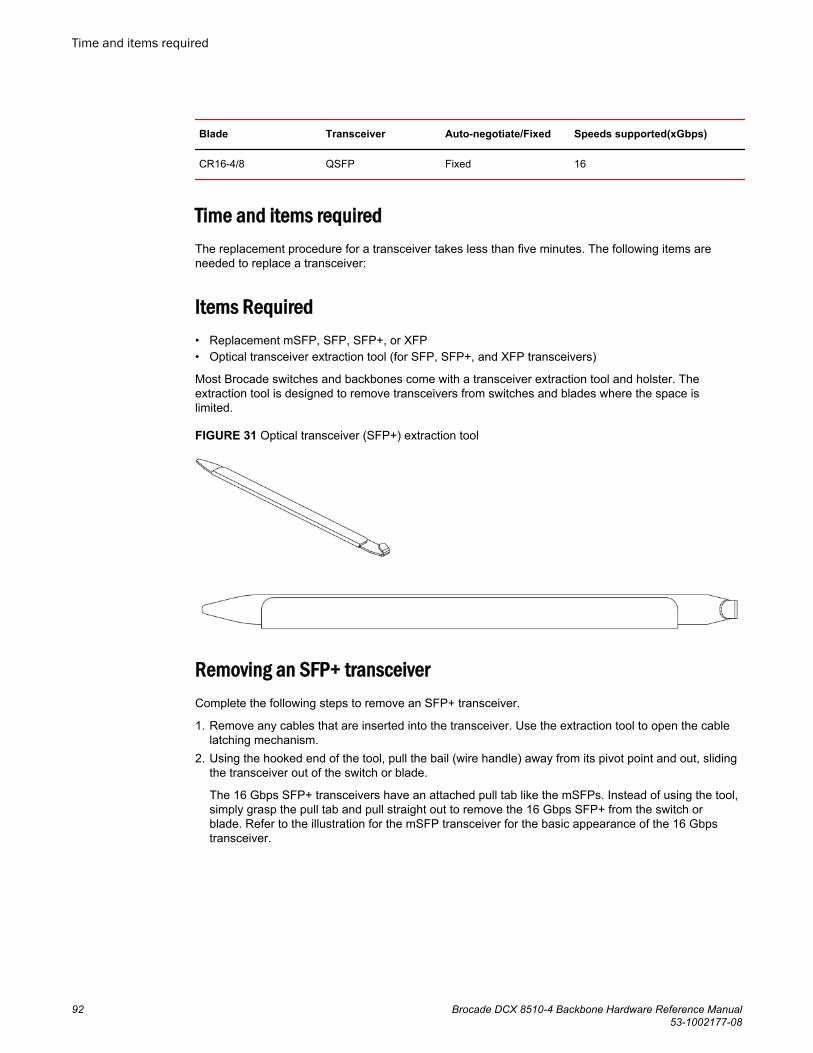
Blade Transceiver Auto-negotiate/Fixed Speeds supported(xGbps)
CR16-4/8 QSFP Fixed 16
Time and items requiredThe replacement procedure for a transceiver takes less than five minutes. The following items areneeded to replace a transceiver:
Items Required• Replacement mSFP, SFP, SFP+, or XFP• Optical transceiver extraction tool (for SFP, SFP+, and XFP transceivers)
Most Brocade switches and backbones come with a transceiver extraction tool and holster. Theextraction tool is designed to remove transceivers from switches and blades where the space islimited.
FIGURE 31 Optical transceiver (SFP+) extraction tool
Removing an SFP+ transceiverComplete the following steps to remove an SFP+ transceiver.
1. Remove any cables that are inserted into the transceiver. Use the extraction tool to open the cablelatching mechanism.
2. Using the hooked end of the tool, pull the bail (wire handle) away from its pivot point and out, slidingthe transceiver out of the switch or blade.
The 16 Gbps SFP+ transceivers have an attached pull tab like the mSFPs. Instead of using the tool,simply grasp the pull tab and pull straight out to remove the 16 Gbps SFP+ from the switch orblade. Refer to the illustration for the mSFP transceiver for the basic appearance of the 16 Gbpstransceiver.
Time and items required
92 Brocade DCX 8510-4 Backbone Hardware Reference Manual53-1002177-08

FIGURE 32 Replacing an optical transceiver
1. Bail
FIGURE 33 Replacing a 16 Gbps SFP+ optical transceiver
Replacing an SFP+ transceiverComplete the following steps to replace an SFP+ transceiver.
1. Making sure that the bail (wire handle) is in the unlocked position, position the optical transceiver sothat the key is oriented correctly to the port. Insert the transceiver into the port until it is firmly seatedand the latching mechanism clicks; then close the bail.
The 16 Gbps SFP+ transceivers do not have bails. Use the tab on the 16 Gbps SFP+ transceivers tohelp gently push the transceiver into the port. Do not push so hard as to bend the tab.
Transceivers are keyed so that they can only be inserted with the correct orientation. If a transceiverdoes not slide in easily, ensure that it is correctly oriented.
2. Position a cable so that the key (the ridge on one side of the cable connector) is aligned with the slotin the transceiver. Insert the cable into the transceiver until the latching mechanism clicks.
Cables are keyed so that they can be inserted in only one way. If a cable does not slide in easily,ensure that it is correctly oriented. Do not insert a cable intended for an mSFP transceiver into a
Replacing an SFP+ transceiver
Brocade DCX 8510-4 Backbone Hardware Reference Manual 9353-1002177-08
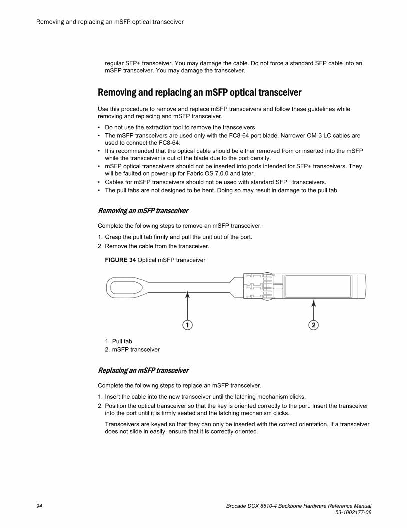
regular SFP+ transceiver. You may damage the cable. Do not force a standard SFP cable into anmSFP transceiver. You may damage the transceiver.
Removing and replacing an mSFP optical transceiverUse this procedure to remove and replace mSFP transceivers and follow these guidelines whileremoving and replacing and mSFP transceiver.
• Do not use the extraction tool to remove the transceivers.• The mSFP transceivers are used only with the FC8-64 port blade. Narrower OM-3 LC cables are
used to connect the FC8-64.• It is recommended that the optical cable should be either removed from or inserted into the mSFP
while the transceiver is out of the blade due to the port density.• mSFP optical transceivers should not be inserted into ports intended for SFP+ transceivers. They
will be faulted on power-up for Fabric OS 7.0.0 and later.• Cables for mSFP transceivers should not be used with standard SFP+ transceivers.• The pull tabs are not designed to be bent. Doing so may result in damage to the pull tab.
Removing an mSFP transceiver
Complete the following steps to remove an mSFP transceiver.
1. Grasp the pull tab firmly and pull the unit out of the port.2. Remove the cable from the transceiver.
FIGURE 34 Optical mSFP transceiver
1. Pull tab2. mSFP transceiver
Replacing an mSFP transceiver
Complete the following steps to replace an mSFP transceiver.
1. Insert the cable into the new transceiver until the latching mechanism clicks.2. Position the optical transceiver so that the key is oriented correctly to the port. Insert the transceiver
into the port until it is firmly seated and the latching mechanism clicks.
Transceivers are keyed so that they can only be inserted with the correct orientation. If a transceiverdoes not slide in easily, ensure that it is correctly oriented.
Removing and replacing an mSFP optical transceiver
94 Brocade DCX 8510-4 Backbone Hardware Reference Manual53-1002177-08

Removing and replacing a QSFP optical transceiverUse this procedure to remove and replace QSFP transceivers supported on the FC16-64 port bladesand core switch blades. Do not use the extraction tool to remove the QSFP transceivers. Follow theseguidelines while removing and replacing QSFP transceivers:
• The QSFP transceivers are used only with the FC16-64 port blades and core switch blades.However, the part numbers of QSFP transceivers supported on FC16-64 port blade and the coreblades are not the same and are not interchangeable.
Qualified transceivers for FC16-64 port blade and the core bladesTABLE 11
Brocade partnumber
Part type Cable length Port speeds Supported blades
57-1000294-01 QSFP transceiver 100 m OM4 Auto-negotiable 4-, 8-,and 16-Gbps
FC16-64
57-1000267-01 QSFP transceiver 100 m OM4 Only fixed 16-Gbps CR16-4/8
57-0000090-01 QSFP transceiver 50 m OM3
• It is recommended that the optical cable should be either removed from or inserted into the QSFPwhile the transceiver is out of the blade due to the port density.
• QSFP optical transceivers should not be inserted into ports intended for SFP+ or mSFP transceivers.They will be faulted on power-up.
• Cables for QSFP transceivers should not be used with standard SFP+ or mSFP transceivers.
• The pull tabs are not designed to be bent. Doing so may result in damage to the pull tab.
Removing a QSFP transceiver
Complete the following steps to remove a QSFP cable.
1. Grasp the rubber housing on the end of the cable and pull it straight out of the QSFP transceiver.2. If the QSFP transceiver also needs to be replaced, remove the QSFP transceiver by rotating the bail
down and using the bail to pull the transceiver out of the connector on the blade.3. Repeat for each cable that requires replacement.
FIGURE 35 QSFP transceiver (bail open)
1. QSFP transceiver2. Bail
Removing and replacing a QSFP optical transceiver
Brocade DCX 8510-4 Backbone Hardware Reference Manual 9553-1002177-08

Replacing a QSFP transceiver
Complete the following steps to replace a QSFP transceiver.
1. If the QSFP transceiver is being replaced, grasp the bail of the new QSFP and push the QSFP intothe connector on the blade until it is firmly seated. The QSFP is keyed to fit into the connector inone way. The status LED initially blinks amber after installation, then displays steady amber.
2. Grasp the QSFP cable by the rubber housing and push it into the QSFP transceiver until it is firmlyseated. The cable housing is keyed to fit into the QSFP in one way.
The status LED displays steady amber until both ends of the cable are inserted and the link isestablished. When the link is fully established, the LED displays steady green.
3. Repeat for each cable that requires replacement.Once all the cables are attached, refer to the Fabric OS Administrator's Guide for the configurationprocedure.
Qualified transceivers for the FC16-64 port blade and the core bladesThe following table shows the qualified transceivers for the FC16-64 port blade and the core blades.
Qualified transceivers for FC16-64 port blade and the core bladesTABLE 12
Brocade partnumber
Part type Cable length Port speeds Supported blades
57-1000294-01 QSFP transceiver 100 m OM4 Auto-negotiable 4-, 8-,and 16-Gbps
FC16-64
57-1000267-01 QSFP transceiver 100 m OM4 Only fixed 16-Gbps CR16-4/8
57-0000090-01 QSFP transceiver 50 m OM3
NOTEThe QSFP transceivers supported on FC16-64 port blade are not interchangeable with QSFPtransceivers supported on the core blades.
Inter-chassis link (ICL) cable removal and replacementUse this procedure to remove and replace ICL QSFP cables. Follow these guidelines while removingand replacing ICL QSFP cables.
• The QSFP ports on the core switch blades can be used only with an inter-chassis link (ICL) license.After the addition or removal of a license, the license enforcement is performed on the ports onlywhen the portdisable and portenable commands are issued on the ports. An ICL license must beinstalled on all Brocade Backbones forming the ICL connection. Beginning with Fabric OS v7.0.1,up to nine neighboring Brocade DCX 8510 series chassis can be connected with the QSFP cables.Under Fabric OS v7.0.0, six chassis can be connected.
• For the Brocade DCX 8510 Backbones, an off-the-shelf QSFP cable up to 50 meters long can beused as an ICL cable.
• For the Brocade DCX 8510 Backbones, if the QSFP cables are not used, make sure the rubbergaskets are in the QSFP transceivers.
Replacing a QSFP transceiver
96 Brocade DCX 8510-4 Backbone Hardware Reference Manual53-1002177-08

The following table describes the connector port LED patterns and the recommended actions for thosepatterns.
ICL QSFP connector port LEDs TABLE 13
LED purpose Color Status Recommended action
QSFP connectorstatus
No light (LED isoff)
No QSFP module, all four QSFPports are disabled.
No action is required if QSFP notpresent or verify that the QSFP is fullyinserted.
Steady amber QSFP module is in, all four portshave no signal/no sync.
No action required if QSFP only isinstalled or ensure that the cable isproperly connected. If the LED remainsamber, consult the Brocade DCX8510-4 supplier.
Blinking amber Port is disabled or faulted, FC linkactivity, segmented, loopbackmode, also during transitionbetween QSFP cable insertion andconfirmation.
Check for console messages or wait forall four ports to come online.
Steady green Both ends of QSFP cable are inand all ports are online. Full link isestablished.
No action required.
Follow this procedure to install the QSFP cables. Refer to the Fabric OS Administrator's Guide for theconfiguration procedure and requirements.
The following figure shows a QSFP cable and transceiver. The QSFP connectors on the core bladesare labeled by trunk group (trunking is optional) for ease of installation. The subsequent figures showacceptable cabling configurations for the ICL feature. The recommended topology is the parallel typewhere there are four QSFP cables connected between any pair of Brocade DCX 8510 series chassis.The full mesh configuration is also supported.
FIGURE 36 QSFP cable and transceiver
Time and items requiredThe replacement procedure for an ICL cable takes less than five minutes. Only a replacement ICL cableis required for this procedure.
Removing an ICL cableComplete the following steps to remove a QSFP cable.
Time and items required
Brocade DCX 8510-4 Backbone Hardware Reference Manual 9753-1002177-08

1. Grasp the rubber housing on the end of the cable and pull it straight out of the QSFP transceiver.2. If the QSFP transceiver also needs to be replaced, remove the QSFP transceiver by rotating the
bail down and using the bail to pull the transceiver out of the connector on the blade.3. Repeat for each cable that requires replacement.
FIGURE 37 QSFP transceiver (bail open)
1. QSFP transceiver2. Bail
Replacing an ICL cableComplete the following steps to replace a QSFP cable.
1. If the QSFP transceiver is being replaced, grasp the bail of the new QSFP and push the QSFP intothe connector on the blade until it is firmly seated. The QSFP is keyed to fit into the connector inone way. The status LED initially blinks amber after installation, then displays steady amber.
2. Grasp the QSFP cable by the rubber housing and push it into the QSFP transceiver until it is firmlyseated. The cable housing is keyed to fit into the QSFP in one way.
The status LED displays steady amber until both ends of the cable are inserted and the link isestablished. When the link is fully established, the LED displays steady green.
3. Repeat for each cable that requires replacement.Once all the cables are attached, refer to the Fabric OS Administrator's Guide for the configurationprocedure.
Possible ICL configurationsThe following figure illustrates one possible QSFP cable configuration between two DCX 8510 serieschassis. Each of two cores in one chassis should be interconnected with each of two cores in thesecond chassis. This provides for inter-chassis link (ICL) trunking between chassis, ensuringredundancy. Parallel connections between core blades are recommended.
Replacing an ICL cable
98 Brocade DCX 8510-4 Backbone Hardware Reference Manual53-1002177-08

FIGURE 38 QSFP cable connections for Brocade DCX 8510 chassis (sample configuration)
1. Chassis 1 - DCX 8510-82. Chassis 2 - DCX 8510-4
The DCX 8510 chassis can be connected in a core/edge configuration. The following figure shows twocore and four edge chassis. Although DCX 8510-8 chassis are shown in the figure, the chassis can beeither DCX 8510-4 or DCX 8510-8. The cabling scheme should follow the parallel example shown in theprevious figure. Each line in the example actually represents four cables running between the chassis.
Removal and Replacement Procedures
Brocade DCX 8510-4 Backbone Hardware Reference Manual 9953-1002177-08

FIGURE 39 DCX 8510 core/edge ICL topology
The DCX 8510 chassis can also be connected in a full mesh configuration as shown in the followingfigure. Although DCX 8510-8 chassis are shown in the figure, the chassis can be either DCX 8510-4 orDCX 8510-8. In this example, the trunk groups are shown in color.
Removal and Replacement Procedures
100 Brocade DCX 8510-4 Backbone Hardware Reference Manual53-1002177-08

FIGURE 40 DCX 8510 full mesh ICL topology
Brocade DCX 8510-4 chassis removal and replacement
This section describes how to remove and replace the Brocade DCX 8510-4 chassis (with itsbackplane). The basic steps are:
1. Faulty Brocade DCX 8510-4 chassis indicators on page 1022. Recording critical Brocade DCX 8510-4 and SAN information on page 1033. Disconnecting from network and fabric on page 1054. Removing components from the chassis on page 1065. Installing the replacement chassis on page 107
Brocade DCX 8510-4 chassis removal and replacement
Brocade DCX 8510-4 Backbone Hardware Reference Manual 10153-1002177-08

6. Installing components into the new chassis on page 1077. Downloading the configuration on page 1088. Verifying correct operation of system on page 1099. Reconnecting the system to the network and fabric on page 11010.Verifying correct configuration of the fabric on page 111
NOTEThe Brocade DCX 8510-4 must be removed from the fabric and powered off to perform thisprocedure. Contact your support provider if you have any questions about whether the chassisrequires replacement.
Time and items requiredThe chassis replacement takes approximately 3 hours.
The following items are required for the chassis replacement:
• Electrostatic discharge (ESD) grounding strap• ESD grounding pads for protecting all blades and WWN cards• Serial cable and workstation computer with a terminal emulator application (such as HyperTerminal
for Windows systems or TIP for Solaris systems), required only if serial console session used• Pallet jack or hydraulic or assisted lift that raises a minimum of 140 cm (55 in.) and carries a
minimum of 113 kg (250 lb)• A surface on which to place the old chassis, such as a second lift or the pallet originally provided
with the old chassis• #2 Phillips screwdriver
Faulty Brocade DCX 8510-4 chassis indicatorsVerify that replacement of the chassis is necessary. Ensure that the components are firmly seatedwhen troubleshooting, and contact your support provider with any questions about whether the chassisshould be replaced.
Any of the following events might indicate the need to replace the chassis:
• Visible mechanical damage to the chassis, including damage to sheet metal or card guides thatprevents correct installation of a blade.
• Bent or damaged connectors on the backplane (the surface inside the chassis to which the bladesconnect).
• One or more components (such as a power supply, blower assembly, port blade, control processorblade, core switch blade, or WWN card) do not function properly even after the component wasreplaced.
• Intermittent FAULTY codes for blades. Reseat the blade and visually inspect the right ejectorstiffening rail for possible wear or damage. It is important that the blade ejector handles not slip outduring blade installation. If this happens, it is usually due to excessive wear or damage to the right-hand ejector stiffening rail.
• The psShow or fanShow commands continue to show a faulty component even though thecomponent was replaced.
• The slotShow command continues to show a faulty control processor, core switch, or port bladeeven though the blade was replaced.
Time and items required
102 Brocade DCX 8510-4 Backbone Hardware Reference Manual53-1002177-08

Recording critical Brocade DCX 8510-4 and SAN informationAll commands must be entered from a CLI session (Telnet or serial) to the active CP blade unlessotherwise indicated.
NOTERun supportShow, which includes most of the information in the following table and more. Thecustomer should record the location of the .txt files, which are created by the customer in this procedureand are not called out in the supportShow results.
For detailed information about Fabric OS commands, refer to the Fabric OS Command Reference. Usea checklist to ensure that all required information is recorded.
Critical information checklist TABLE 14
Checked? Data Notes
Configuration information
Location of "config-switch.txt" file
Location of "config-miscinfo.txt" file
IP address, subnet mask
WWN for Brocade DCX 8510-4
SAN profile
Location of "SANbefor.txt" file
Notes regarding nsshow output
Notes regarding nsallshow output
Notes regarding switchshowoutput
Notes regarding fabricshow output
Output from supportshow command
Location of "spptshow.txt" file
Notes regarding supportshowoutput
Information about the new chassis
New factory serial number
New serial number (if available)
Recording critical Brocade DCX 8510-4 and SAN information
Brocade DCX 8510-4 Backbone Hardware Reference Manual 10353-1002177-08

1. Open a Telnet session and log in to the Brocade DCX 8510-4 as admin. The default password ispassword. Enable the logging function on your Telnet or serial console connection.
2. Back up the current configuration.
NOTEIf you are using the Virtual Fabric feature, you should run configupload -vf before running theconfigupload command to save the logical switch configuration.
• Enter configUpload -all; then enter the requested information at the prompts.
This command uploads the Brocade DCX 8510-4 configuration to the customer-defined FTP server,making it available for downloading. For more information about this command, refer to the FabricOS Command Reference.
switch:admin> configuploadProtocol (scp or ftp) [ftp]: ftpServer Name or IP Address [host]: 123.123.123.123User Name [user]: Admin24File Name [config.txt]: config-switch0.txtPassword:Upload completeswitch:admin>• Alternatively, you can save the configuration file to a Brocade USB device.
3. Record the WWN value: Enter wwn; then copy the command output into a file named config-miscinfo.txt.
switch:admin> wwn10:00:00:60:69:00:00:0a
4. Record the IP address information.
Enter ipAddrShow -sw; then copy the command output into the config-miscinfo.txt file.
switch:admin> ipaddrshow -swSWITCHEthernet IP Address: 10.32.50.12Ethernet Subnetmask: 255.55.0.0Fibre Channel IP Address: 1.2.3.4Fibre Channel Subnetmask: 255.255.255.0CP0Ethernet IP Address: 10.32.50.10Ethernet Subnetmask: 255.55.0.0HostName : cp0Gateway Address: 10.32.40.1CP1Ethernet IP Address: 10.32.50.11Ethernet Subnetmask: 255.55.0.0HostName : cp1Gateway Address: 10.32.40.1Backplane IP address of CP0 : 10.0.0.6Backplane IP address of CP1 : 10.0.0.7switch:admin>switch:admin>
5. Display and record the manufacturer serial numbers.
Enter chassisShow; then copy the command output into the config-miscinfo.txt file.
"Factory Serial Num" and "Serial Num" are listed under "Chassis/WWN Unit 1." If the current WWNcards are the original cards, the factory serial number listed is the same as the chassis serialnumber.
switch:admin> chassisshowChassis Backplane Revision: 1FSW BLADE Slot: 1Header Version: 2Power Consume Factor: -50Factory Part Num: 60-0001532-03Factory Serial Num: KP000000195
Removal and Replacement Procedures
104 Brocade DCX 8510-4 Backbone Hardware Reference Manual53-1002177-08

Manufacture: Day: 1 Month: 1 Year: 2007Update: Day: 14 Month: 3 Year: 2012Time Alive: 187 daysTime Awake: 3 days<output truncated>CHASSIS/WWN Unit: 1 (in same assembly as WWN Unit: 2)Header Version: 2Power Consume Factor: -3Factory Part Num: 60-0001501-07Factory Serial Num: FT02X805BE2Manufacture: Day: 26 Month: 3 Year: 2007Update: Day: 14 Month: 3 Year: 2009Time Alive: 207 daysTime Awake: 3 days<output truncated>switch:admin>
6. Create a SAN "profile" by entering and recording the information provided by the followingcommands:
• nsShow• nsAllShow• switchShow -qsfp• fabricShow
Copy the command output into a text file named "SANbefor.txt." After the Brocade DCX 8510-4 isrestored to the fabric, this information can be used to verify that no unintentional changes haveoccurred to the fabric.
switch:admin> nsshowEnter Pid COS PortName NodeName TTL<output truncated>switch:admin> nsallshow 12 Nx_Ports in the Fabric<output truncated>switch:admin> switchshowswitchName: switch<output truncated>switch:admin> fabricshowSwitch ID Worldwide Name Enet IP Addr FC IP Addr Name<output truncated>switch:admin>
7. Enter supportShow; then copy the command output into a text file named "spptshow.txt."
NOTEThe supportShow command has a very long output and time for completion. It may last 20 minutesor longer depending on the size of the SAN.
This file provides a backup of all the information that might be required by Technical Support. Theinformation can be used after the Brocade DCX 8510-4 is restored to the fabric to verify that nounintentional changes have occurred to the fabric.
switch:admin> supportshowversion: 7.0.0<output truncated>switch:admin>
8. Record the cable connections between the Brocade DCX 8510-4 and the target device and ports.9. Run supportSave on the active CP. The information recorded can be very important in case you
have difficulties during the replacement process.
Disconnecting from network and fabricComplete the following steps to disconnect the chassis from the network.
Disconnecting from network and fabric
Brocade DCX 8510-4 Backbone Hardware Reference Manual 10553-1002177-08

1. Shut down the Brocade DCX 8510-4 using the sysShutdown command on the active CP.
switch:admin> sysshutdownThis command will shutdown the operating systems on your switch.You are required to power-cycle the switch in order to restore operation.Are you sure you want to shutdown the switch [y/n]?yHA is disabledStopping blade 1 Shutting down the blade....Stopping blade 2 Shutting down the blade....Stopping blade 8 Shutting down the blade....Broadcast message from root (pts/1) Tue Jul 18 14:23:06 2008...The system is going down for system halt NOW !!
DANGERDisconnect the power cord from all power sources to completely remove power from thedevice.
2. Power off the chassis by flipping all AC power switches to the off position. (The power supply statusLED should turn off.)
3. Remove the power cords from the power supplies and the power outlets.4. Remove the chassis door.5. Label the cables connected to all blades and record the connections.6. Disconnect the cables from the SFP+ transceivers in the application and port blades and set them
aside. If you have mSFP transceivers in FC8-64 port blades, or QSFP transceivers in FC16-64 portblades, remove the transceivers and cables together and set them aside. The SFP+ transceiverscan be left in the port blades or removed.
7. Disconnect all cables from the control processor and core switch blades.8. Disconnect any ICL or QSFP cables.
Removing components from the chassisFollow electrostatic discharge (ESD) precautions when removing components. Wear a wrist groundingstrap connected to chassis ground (if the Brocade DCX 8510-4 is plugged in) or a bench ground.
DANGERFor safety reasons, the ESD wrist strap should contain a series 1 megaohm resistor.
1. Remove the chassis door (Chassis door removal and replacement on page 66) if not already done.2. Remove the cable management finger assemblies (Vertical cable management fingers removal and
replacement on page 67).3. Remove the port blades or filler panels (Port, application, and encryption blade removal and
replacement on page 68 and Blade filler panel removal and replacement on page 72).4. Remove the core switch blades (CR16-4) (Core switch blade (CR16-4) removal and replacement on
page 81).5. Remove the control processor blades (CP8) (Control processor blade (CP8) removal and
replacement on page 73).6. Remove the power supplies or filler panels (Power supply removal and replacement on page 84).7. Remove the blower assemblies (Blower assembly removal and replacement on page 86).8. Remove the WWN bezel (logo plate) and WWN cards (WWN card removal and replacement on
page 87).
Removing components from the chassis
106 Brocade DCX 8510-4 Backbone Hardware Reference Manual53-1002177-08

Installing the replacement chassisComplete the following steps to install the replacement chassis.
DANGERUse safe lifting practices when moving the product.
DANGER
A completely empty Brocade DCX 8510-4 chassis weighs approximately 25.4 kg (56 lb) andrequires a hydraulic or assisted lift to install it.
DANGERMake sure the rack or cabinet housing the device is adequately secured to prevent it frombecoming unstable or falling over.
1. If the chassis is in a cabinet, remove it from the cabinet.2. Place the chassis on a lift or on the shipping pallet provided with the original chassis.3. Unpack the new chassis:
a) Cut the bands that encircle the packaging.b) Remove the lid and the kits and foam from the top of the chassis.c) Lift the cardboard box off the chassis and remove the plastic bag from around the chassis.
Save the packing materials for use when returning the old chassis.d) Leave the chassis on top of the plastic shipping tray if the chassis must be transported to
the installation location.
NOTEThe Brocade DCX 8510-4 packaging does not incorporate a wood pallet and palletbrackets. The chassis sits on top of a plastic shipping tray.
4. Use a pallet jack or other assisted lift to transport the new chassis to the installation area. Doorwaysmust be wider than 91 cm (36 in.) to accommodate the chassis on the pallet.
5. Use a lift to raise the chassis to the correct level. If installing the chassis in a cabinet, follow theinstructions provided by the rack kit manufacturer.
Installing components into the new chassisFollow electrostatic discharge (ESD) precautions when installing new components. Wear a wristgrounding strap connected to chassis ground (if the Brocade DCX 8510-4 is plugged in) or a benchground.
DANGERFor safety reasons, the ESD wrist strap should contain a series 1 megaohm resistor.
1. Replace the WWN bezel (logo plate) and WWN cards (WWN card removal and replacement on page87).
2. Replace the blower assemblies (Blower assembly removal and replacement on page 86).3. Replace the power supplies or filler panels (Power supply removal and replacement on page 84).
Installing the replacement chassis
Brocade DCX 8510-4 Backbone Hardware Reference Manual 10753-1002177-08
4. Replace the control processor blades (CP8) (Control processor blade (CP8) removal andreplacement on page 73).
5. Replace the core switch blades (CR16-4) (Core switch blade (CR16-4) removal and replacement onpage 81).
6. If ICL cables are not used, insert EMI plugs in the ICL sockets in the core switch blades (CR16-4).7. Replace the port blades or filler panels (Port, application, and encryption blade removal and
replacement on page 68 and Blade filler panel removal and replacement on page 72).8. Replace the cable management finger assemblies (Vertical cable management fingers removal and
replacement on page 67).9. Connect the power cords to the power supplies and the power outlets.10.Replace the chassis door (Chassis door removal and replacement on page 66).11.Power on the Brocade DCX 8510-4 (Installing components into the new chassis).
The Brocade DCX 8510-4 performs a power-on self-test (POST). The POST takes a minimum ofthree minutes and is complete when LED activity returns to the standard state.
12.Verify that the Brocade DCX 8510-4 is powered on and POST is complete (all power LED indicatorson the blades should be a steady green).
13.Verify that all components are functioning correctly by checking their LEDs. If the LEDs do notindicate correct operation, try reinstalling the corresponding component.
Downloading the configurationOnce the chassis and its various components have been reassembled and powered back on, use theconfigDownload command to restore the original configuration. The configDownload command canbe entered through a Telnet or serial session, but the Brocade DCX 8510-4 must have an Ethernetconnection to the server name or IP address of the host for the download process to complete. Formore information, refer to the help configdownload command or the Fabric OS CommandReference.
Complete the following steps to download the configuration.
1. Log in to the Brocade DCX 8510-4 as admin.
switch:admin> loginlogin: adminpassword: xxxxxxxxswitch:admin>
NOTEIf you are using the Virtual Fabric feature, you must run configdownload -vf before running theconfigdownload command to restore the logical switch configuration.
2. Enter the chassisDisable command.3. Enter the configDownload command.
switch:admin> configdownload -allServer Name or IP Address [host]: 123.123.123.123User Name [None]: Admin24File Name [config.txt]: config-switch.txtPassword: xxxxxxxxdownload completeswitch:admin>
4. Reboot the Brocade DCX 8510-4.
Downloading the configuration
108 Brocade DCX 8510-4 Backbone Hardware Reference Manual53-1002177-08

Verifying correct operation of systemComplete the following steps to verify the correct operation of the Brocade DCX 8510-4.
1. Log in to the Brocade DCX 8510-4 as admin.
switch:admin> loginlogin: adminpassword: xxxxxxxxswitch:admin>
2. Enter the slotShow -m command and verify that all the installed cards are detected and that theirstatus is operational (enabled). The example is from a DCX chassis. The other backbone chassis aresimilar.
switch:admin> slotShow -mSlot Blade Type ID Model Name Status-------------------------------------------------- 1 SW BLADE 97 FC16-32 ENABLED 2 SW BLADE 77 FC8-64 ENABLED 3 CORE BLADE 99 CR16-4 ENABLED 4 CP BLADE 50 CP8 ENABLED 5 CP BLADE 50 CP8 ENABLED 6 CORE BLADE 99 CR16-4 ENABLED 7 SW BLADE 96 FC16-48 ENABLED 8 SW BLADE 77 FC8-64 ENABLED
3. Verify that the Brocade DCX 8510-4 is functioning correctly by entering switchShow orswitchStatusShow.
This switchShow command displays the Brocade DCX 8510-4 and port status information. Theexample is from a DCX 8510-8. The other backbone chassis are similar.
switch:FID128:admin> switchshowswitchName: DCX8510_8switchType: 120.1switchState: OnlineswitchMode: NativeswitchRole: SubordinateswitchDomain: 80switchId: fffc50switchWwn: 10:00:00:05:1e:39:e4:5azoning: ON (ZONE_CONFIG_NAME)switchBeacon: OFFFC Router: OFFAllow XISL Use: OFFLS Attributes: [FID: 128, Base Switch: No, Default Switch: Yes, Address Mode 0]Index Slot Port Address Media Speed State Proto=======================================================0 1 0 500000 -- 4G No_Module FC1 1 1 500100 -- 4G No_Module FC2 1 2 500200 -- 4G No_Module FC3 1 3 500300 -- 4G No_Module FC4 1 4 500400 -- 4G No_Module FC(output truncated)DCX-4_130:admin> switchshowswitchName: DCX-4_130switchType: 121.3switchState: OnlineswitchMode: NativeswitchRole: PrincipalswitchDomain: 130switchId: fffc82switchWwn: 10:00:00:05:33:03:2c:00zoning: ON (ZONE_CONFIG_NAME)switchBeacon: OFFFC Router: ONFC Router BB Fabric ID: 10Address Mode: 0Index Slot Port Address Media Speed State Proto======================================================= 0 1 0 820000 id N8 Online FC F-Port 10:00:00:05:1e:f8:a0:b4
Verifying correct operation of system
Brocade DCX 8510-4 Backbone Hardware Reference Manual 10953-1002177-08

1 1 1 820100 id N8 Online FC F-Port 10:00:00:05:33:26:0e:65 2 1 2 820200 id N8 Online FC F-Port 10:00:00:05:33:48:5e:f5 3 1 3 820300 id N8 Online FC F-Port 10:00:00:05:1e:f8:a0:b3(output truncated)
4. Verify that all the IP address information is correct by entering ipAddrShow and checking theresults against the IP information recorded in the config-miscinfo.txt file.
switch:admin> ipaddrshowSWITCHEthernet IP Address: xxx.xxx.xxx.12Ethernet Subnetmask: 255.55.0.0Fibre Channel IP Address: 1.2.3.4Fibre Channel Subnetmask: 255.255.255.0CP0Ethernet IP Address: xxx.xxx.xxx.10Ethernet Subnetmask: 255.55.0.0HostName : cp0Gateway Address: xxx.xxx.xxx.1CP1Ethernet IP Address: xxx.xxx.xxx.11Ethernet Subnetmask: 255.55.0.0HostName : cp1Gateway Address: .1Backplane IP address of CP0 : 10.0.0.4Backplane IP address of CP1 : 10.0.0.5switch:admin>switch:admin>
Reconnecting the system to the network and fabricRefer to the cable routing information recorded in Cable routing table on page 111 for the followingsteps.
Complete the following steps to reconnect the Brocade DCX 8510-4 to the network and fabric.
1. Connect the CP blades to the local area network.a) Insert the appropriate Ethernet cables into each Ethernet port.b) Connect the other ends to an Ethernet 10/100 Base-T LAN, if not already connected.
NOTEThe Brocade DCX 8510-4 can be accessed by remote connection using any of theavailable management tools, such as Telnet or Web Tools. Ensure that the Brocade DCX8510-4 is not modified using other connections during the rest of this procedure.
2. Reconnect the transceivers and cables to the port blades.
NOTEThe ports and cables used in trunking groups must meet specific requirements. For a list of theserequirements, refer to theFabric OS Administrator's Guide.
a) Position one of the transceivers so that the key is oriented correctly to the port and insertthe transceiver into the port until it is firmly seated and the latching mechanism clicks.
b) Select the cable that corresponds to the port and position it so that the key (the ridge onone side of the cable connector) is aligned with the slot in the transceiver. Insert the cableinto the transceiver until the latching mechanism clicks.
c) Repeat step a and step b for the remaining ports.d) Organize the cables as required.
Reconnecting the system to the network and fabric
110 Brocade DCX 8510-4 Backbone Hardware Reference Manual53-1002177-08

NOTE
Do not route cables in front of the air exhaust vents.
Verifying correct configuration of the fabricCopying the command outputs from this section into a file is recommended.
1. Create an "after" SAN profile by entering the following commands and copying the output to a text filenamed SANafter.txt:
• nsShow• nsAllShow• switchShow• fabricShow• lscfg --show (if using the Virtual Fabric feature)
switch:admin> nsshowType Pid COS PortName NodeName TTL(sec) N 020f00; 3;10:00:00:01:73:00:29:46;10:00:00:01:73:00:29:46; na Fabric Port Name: 20:0f:00:60:69:90:03:f0<output truncated>switch:admin> nsallshow{ 020f00 021fda 021fdc 021fe0 021fe15 Nx_Ports in the Fabric}switch:admin> switchshowswitchName: rsl8-st03-dcx-01<output truncated>switch:admin> fabricshowSwitch ID Worldwide Name Enet IP Addr FC IP Addr Name<output truncated>switch:admin>lscfg --showCreated switches: 128(ds) 1 2(bs)Port 0 1 2 3 4 5 6 7 8 9-------------------------------------------------------------------FID 1 | 1 | 1 | 1 | 1 | 128 | 128 | 128 | 128 | 128 |<output truncated>switch:admin>
2. Determine any differences between the information in the SANafter.txt file and the information in theSANbefor.txt file created earlier. In particular, look for differences in the following:
• Device types• Number of devices• ISL and port states• Number of switches in the fabric
3. Resolve any issues or unintentional changes to the Brocade DCX 8510-4 or fabric:
• If there are any mechanical problems, try reseating the associated component.• If the configuration information is not correct for the Brocade DCX 8510-4, modify as required.• If other issues exist, contact your support provider.
Cable routing tableThe following table is a 64-port template for a cable routing table. Make copies of the table to cover thetotal number of ports in the Brocade DCX 8510-4.
Verifying correct configuration of the fabric
Brocade DCX 8510-4 Backbone Hardware Reference Manual 11153-1002177-08

Cable routing table for Brocade DCX 8510-4 (64 ports shown) TABLE 15
Slot/port Cable labels Connected device Slot/port of device
Slot Port Switch end Device end
0
1
2
3
4
5
6
7
8
9
10
11
12
13
14
15
16
17
18
19
20
21
22
23
24
Removal and Replacement Procedures
112 Brocade DCX 8510-4 Backbone Hardware Reference Manual53-1002177-08

Cable routing table for Brocade DCX 8510-4 (64 ports shown) (Continued)TABLE 15
Slot/port Cable labels Connected device Slot/port of device
25
26
27
28
29
30
31
32
33
34
35
36
37
38
39
40
41
42
43
44
45
46
47
48
49
50
Removal and Replacement Procedures
Brocade DCX 8510-4 Backbone Hardware Reference Manual 11353-1002177-08

Cable routing table for Brocade DCX 8510-4 (64 ports shown) (Continued)TABLE 15
Slot/port Cable labels Connected device Slot/port of device
51
52
53
54
55
56
57
58
59
60
61
62
63
Removal and Replacement Procedures
114 Brocade DCX 8510-4 Backbone Hardware Reference Manual53-1002177-08

Application and Encryption Blades
● Introduction................................................................................................................... 115● FS8-18 blade.................................................................................................................115● FX8-24 blade.................................................................................................................115
IntroductionThis appendix provides details about the application and encryption blades that are available optionallyfor the Brocade DCX 8510-4. Contact your Brocade DCX 8510-4 supplier for additional information.
FS8-18 bladeThe FS8-18 encryption blade is a high performance 16-port autosensing blade with data cryptographic(encryption/decryption) and data compression capabilities designed for enterprises to secure their dataagainst theft or unauthorized use and to compress tape data for maximum utilization of tape media. Theencryption blade is a network-based solution that secures data-at-rest for heterogeneous tape drives,disk array LUNs, and virtual tape libraries.
The FS8-18 blade provides the following major features:
• 16 autosensing F_Ports, FL_Ports, E_Ports, EX_Ports, and M_Ports at 8 Gbps FC ports• 16 SFP media interfaces• Encryption engines• Key management/generation• Key management with these hardware interfaces:
‐ Two 1000Base copper type media interfaces‐ One smart card interface
• Security supervisor tamper detection and response capability• Common Criteria (CC) EAL-3 compliant
FX8-24 bladeThe FX8-24 blade has 12 external Fibre Channel (FC) SFP ports supporting the Fibre Channel RoutingServices and 10 external 1 Gigabit Ethernet (GbE or GE) SFP ports supporting the Fibre Channel OverIP (FCIP) feature. There are also 2 licensable external 10 Gigabit Ethernet (10GbE or 10GE) SFP portssupporting FCIP. It operates with the Brocade Fabric Operating System and can communicate withanother FX8-24 or a Brocade 7800 for both Fibre Channel Routing Services and FCIP, or a BrocadeAP7420 for Fibre Channel Routing Services.The GbE ports on the FX8-24 are not compatible with theGbE ports on the FR4-18i blade, the Brocade 7500 switch, and the Brocade 7840 switch.
Brocade DCX 8510-4 Backbone Hardware Reference Manual 11553-1002177-08

NOTEThe port diagram on the front panel uses the abbreviations GE for 1 GbE ports and 10 GE for 10 GbEports.
NOTE
The 10 GbE SFPs used in the FX8-24 blade and the 10 Gbps FC SFPs used in the FC16-32/48blades are not interchangeable.
The FX8-24 operates in one of three modes: 1) ten 1 GbE ports, 2) ten 1 GbE ports and one 10 GbEport, or 3) two 10 GbE ports depending on licensing and subsequent configuration of GbE port mode.If operating in 10 GbE mode the other end of the circuit must also be an FX8-24 operating in either 10GbE mode or dual mode with the corresponding VE_Ports in 10 GbE mode. All GbE ports on theblade can be configured to work with either copper or optical SFPs.
The FX8-24 blade is intended as a platform for FCIP and Fibre Channel Routing Services. Refer to theFabric OS Administrator's Guide for information on configuring these features.
The FX8-24 blade provides the following hardware features:
• 12 autosensing FC ports with link speeds of 1, 2, 4, or 8 Gbps• Ten GbE ports supporting FCIP with fixed link speed at 1 Gbps• Two 10 GbE ports (licensable) supporting FCIP with fixed link speed at 10 Gbps
The FX8-24 blade also provides the following functionality features:
• FCIP• Compression (on FC frames before FCIP encapsulation)• FC Routing (licensable)• FCIP Trunking (licensable) with network-based failure recovery (failover only) and load balancing• Multiple circuits per trunk:
‐ Four per trunk through the GbE ports‐ Ten per trunk through the 10 GbE ports
• SO-TCP with reorder resistance• FastWrite over FCIP• Tape pipelining over FCIP• FICON XRC emulation and tape pipelining over FCIP (licensable)• FICON CUP (licensable)• Virtual E_Ports• FCIP QoS• Support for 200 ms RTT (on a limited number of GbE ports)• Adaptive Rate Limiting (licensable)• TCP performance graphing in Web Tools• FCIP Tunnels:
‐ A maximum of 10 FCIP Tunnels for all GbE ports‐ Four tunnels maximum per GbE port‐ Two 10 GbE ports can support up to ten FCIP tunnels each‐ Each FCIP tunnel is represented and managed as a virtual Fibre Channel E_Port‐ Fibre Channel Routing Services can be used over the FCIP link
Application and Encryption Blades
116 Brocade DCX 8510-4 Backbone Hardware Reference Manual53-1002177-08

‐ The Link Cost is equal to the sum of all established/low metric (or currently active) circuits’MAX rates in the tunnel
‐ Fabrics connected through FCIP merge if the ports are configured as VE_Ports, and do notmerge if they are configured as VEX_Ports. If VE_Ports are used in a Fibre ChannelRouting Services backbone fabric configuration, then the backbone fabric merges, but theEX_Port-attached edge fabrics do not merge. For more information, refer to the Fabric OSAdministrator's Guide
• Up to three FC trunking groups:
‐ Trunk group 0: FC ports 0, 1‐ Trunk group 1: FC ports 6, 7‐ Trunk group 2: FC ports 2, 3, 4, 5, 8, 9, 10, 11
Application and Encryption Blades
Brocade DCX 8510-4 Backbone Hardware Reference Manual 11753-1002177-08

FX8-24 blade
118 Brocade DCX 8510-4 Backbone Hardware Reference Manual53-1002177-08

Diagnostics and Troubleshooting
● Introduction................................................................................................................... 119● Obtaining chassis and component status..................................................................... 119● Interpreting POST and boot results...............................................................................120● Diagnostics....................................................................................................................121● Troubleshooting............................................................................................................ 122
IntroductionFor information about troubleshooting the entire fabric, refer to the Fabric OS Troubleshooting andDiagnostics Guide.
The Brocade DCX 8510-4 includes a number of diagnostic aids to assist with troubleshooting, includingLEDs on the hardware, commands that display current status, diagnostic tests for hardware andsoftware, and error messages. In addition, a number of managing and monitoring features are available,such as Fabric Manager, Web Tools, Fabric Watch, and Advanced Performance Monitoring.
If the Brocade DCX 8510-4 does not operate as expected, the following steps can be taken to diagnosethe problem:
• Check the LEDs and refer to the LED tables (Monitoring System Components on page 49) forinterpretation and recommended actions.
• Review the results of the last POST run by the Brocade DCX 8510-4 (Interpreting POST and bootresults on page 120).
• Review the error logs. (Refer to the Fabric OS Troubleshooting and Diagnostics Guide for moreinformation).
‐ Review RASlog entries.‐ Use the sensorShow command to determine the status of the hardware components.‐ Run diagnostic tests (Diagnostics on page 121).‐ Reboot the Brocade DCX 8510-4 or power the entire chassis off and then on (Powering off
the Brocade DCX 8510-4 on page 48 and Providing power to the Brocade DCX 8510-4Backbone on page 27).
If the problem is still unresolved after these steps, contact your support provider.
Obtaining chassis and component statusThe CLI commands in the following table provide status and environmental information about thechassis and its components. These commands provide information only, and they do not interrupt trafficflow. For more information about these commands, refer to the Fabric OS Command Reference.
Brocade DCX 8510-4 Backbone Hardware Reference Manual 11953-1002177-08

Environmental status and maintenance commands TABLE 16
Command Information displayed
sensorShow Temperature readings for the port blades
Temperature readings for the CP blades
Status and RPM of all operational fans
Status of all operational power supplies
tempShow Temperature readings for the port blades
Temperature readings for the CP blades
psShow Status of all operational power supplies
fanShow Status and RPM of all operational fans
chassisShow Serial number, time awake, and additional information about each component
slotShow Slot occupancy
errShowerrDump System error log. Refer to the Fabric OS Message Reference for more information on themessages in this log.
Interpreting POST and boot resultsThe Brocade DCX 8510-4 performs Power-On Self-Test (POST) by default each time the chassis ispowered on, rebooted, or reset. The Brocade DCX 8510-4 can be rebooted using the reboot (toreboot each CP individually) or fastBoot commands. The fastBoot command reboots the switcheswithout running POST. If the active CP blade is rebooted, it fails over to the standby CP blade.
POSTThe Brocade DCX 8510-4 automatically performs POST each time it is powered on or reset.
To verify that POST has completed without error:
• Verify that all LEDs return to a normal state after POST completes.
If one or more LEDs do not return to a normal state, and this is not due to the Brocade DCX 8510-4being set to beacon, refer to the relevant LED table to identify and correct the problem. For portblades, and CP and core switch blades, the slotShow command can be used to check the status ofthe slots. For information about turning beaconing on or off, refer to the Fabric OS Administrator'sGuide.
• Verify that the switch prompt displays when POST completes.
If it does not display, POST was not successfully completed. Contact the Brocade DCX 8510-4supplier for support.
• Review the system error log using the errShow or errDump commands.
Interpreting POST and boot results
120 Brocade DCX 8510-4 Backbone Hardware Reference Manual53-1002177-08

Any errors detected during POST are written to the system log, which is accessible through theerrShow command. For information about error messages, refer to the Fabric OS MessageReference.
POST includes the following steps:
1. Preliminary POST diagnostics are run.2. Operating system is initialized.3. Hardware is initialized.4. Diagnostic tests are run on several functions, including circuitry, port functionality, ability to send and
receive frames, all aspects of memory, parity, statistics counters, and serialization.
BootIn addition to POST, boot includes the following steps after POST is complete:
1. Universal port configuration is performed.2. Links are initialized.3. Fabric is analyzed. If any ports are connected to other switches, the Brocade DCX 8510-4
participates in a fabric configuration.4. The Brocade DCX 8510-4 obtains a domain ID and assigns port addresses.5. Unicast routing tables are constructed.6. Normal port operation is enabled.
DiagnosticsDiagnostic tests are automatically run during POST to check the status of the Brocade DCX 8510-4.Any error messages generated during POST are sent to the error logs and to the serial console, ifconnected.
Diagnostic tests can also be run manually to test and troubleshoot the hardware and the firmware,including internal connections and circuitry, transceivers, and port cables. However, diagnostic tests aregenerally intended for use by support personnel.
NOTEError messages do not necessarily indicate that the Brocade DCX 8510-4 requires maintenance.
Each diagnostic test can be implemented by entering the related command through a Telnet or serialsession. For a list of diagnostic tests and commands, refer to the Fabric OS Administrator's Guide
All diagnostic tests are run at all supported link speeds. They might temporarily lock the transmit andreceive speeds to a specific speed. Some diagnostic tests require interconnecting the ports to eachother or using loopback plugs. If ports are interconnected, the media (cables and transceivers) at eachend of the connection must be of the same type. For example, short wavelength media must beconnected to short wavelength media, and likewise with long wavelength media and copper media.
For more information about diagnostic tests and how to run them, refer to the Fabric OS Administrator'sGuide and the Fabric OS Command Reference. For information about system error messages(errShow or errDump ), refer to the Fabric OS Troubleshooting and Diagnostics Guide.
Boot
Brocade DCX 8510-4 Backbone Hardware Reference Manual 12153-1002177-08

TroubleshootingThe following table provides a list of issues, possible causes, and recommended actions.
Troubleshooting the Brocade DCX 8510-4TABLE 17
Issue Possible cause Recommended action
Entire chassis powers offautomatically.
Power supplies areinadequate to support theinstalled components.
Add an additional power supply.
Several or all components arenot operating.
One or both power cablesmay not be connected to alive source.
Ensure that both power cables are connected to liveoutlets.
One or both AC powerswitches might be off.
Ensure that both AC power switches are on (ACswitches light up green when on).
Serial connection is faulty orserial port logs have incorrector missing information.
Serial cable is notconnected correctly.
Ensure that the cable is firmly connected toworkstation computer and to the Brocade DCX8510-4.
Terminal emulatorapplication parameters arenot set correctly.
Ensure that the terminal emulator application isconfigured as follows: 9600 bits per second, 8databits, no parity, 1 stop bit, no flow control.
Serial port might beincompatible (only RS-232is supported).
Ensure that the Brocade DCX 8510-4 is connectedto an RS-232 port. RS-423 serial ports mightexperience difficulties due to corner-caseincompatibilities of the standards.
Pins on the serial cable orserial port might bedamaged.
Remove the cable and inspect the pins on the cableand in the serial port. Do not reinstall if the pins oneither component have any visible damage, as thiscould damage the pins on the other component.Replace the components as required.
CP Ethernet link speed isdifferent than expected or alink cannot be established.
There might be a conflictwith the CP Ethernet linkspeed negotiation set upby the network.
Specify the CP Ethernet link speed by typing theifModeSet command.
For more information about Ethernet connectivity tothe Brocade DCX 8510-4, refer to the LANguidelines provided through the MyBrocade website.
Configuration data isinaccurate or cannot beaccessed.
Chassis was poweredoff/on while a WWN cardwas uninstalled or failed.
Install an operational WWN card and power thesystem off/on again.
The Brocade DCX 8510-4was rebooted while anWWN card wasuninstalled or failed.
Initial setup results in IPaddress/Domain ID conflict.
The Brocade DCX 8510-4was connected to thefabric before beingconfigured.
Refer to the Fabric OS Administrator's Guide forconfiguration information.
Troubleshooting
122 Brocade DCX 8510-4 Backbone Hardware Reference Manual53-1002177-08

Troubleshooting the Brocade DCX 8510-4 (Continued)TABLE 17
Issue Possible cause Recommended action
LEDs on one or morecomponents are changingrapidly or do not indicate ahealthy state.
The Brocade DCX 8510-4might be booting orrunning POST.
Verify that boot and POST are complete. TheBrocade DCX 8510-4 requires a minimum of 3minutes, usually, after power-on to complete POST.
Beaconing might be on forthe entire Brocade DCX8510-4 or for individualcomponents.
Determine whether beaconing is on by typing theswitchShow command and determine whetherswitch beaconing or blade beaconing are on.
Individual componentsmight have failed.
Refer to the LED tables in Monitor SystemComponents for interpretation and recommendedactions.
Pins on the componentsmight be damaged.
Remove the component from the chassis andinspect the pins on the component and inside thechassis. Do not reinstall if pins on either componentare damaged, as this could damage pins on othercomponents. Replace the parts as required.
None of the LEDs on acomponent are on.
Component might not beseated correctly.
Ensure that the Brocade DCX 8510-4 has powerand the component is firmly seated. If the problemcontinues, enter the sensorShow command todetermine the component status. If the component isa CP blade or port blade, enter the slotShowcommand to determine the status.
Component might havefailed.
Replace the component as necessary.
CP blades are failing overfrequently.
There is excessive serialport activity.
Ensure that the serial port activity remains belowspecified amount.
CP blade is attached to anEthernet with high trafficloads.
Ensure that the Ethernet traffic remains belowspecified amount
Chassis is overheated. Enter the tempshow and sensorShow commandsto check internal temperature. If components areoverheating, shut down port blades as necessary toreturn the temperature to operating range. Also trymoving the blades in the chassis because it ispossible that airflow might not be adequate to cooleverything in certain configurations.
One or more port blades haveeither shut down or failedPOST as indicated by theerror log.
Blades might beoverheated.
Enter the sensorShow command to check theinternal temperature readings. If components areoverheating, shut down port blades as necessary toreturn the temperature readings to the operatingranges. Also try moving the blades in the chassisbecause it is possible that airflow might not beadequate to cool everything in certainconfigurations.
Diagnostics and Troubleshooting
Brocade DCX 8510-4 Backbone Hardware Reference Manual 12353-1002177-08

Troubleshooting the Brocade DCX 8510-4 (Continued)TABLE 17
Issue Possible cause Recommended action
Blades might be faulty. Enter the slotShow command to determine status.For more information, enter the diagDisablePostcommand; then, use the slotPowerOff slot numberand slotPowerOn slot number command. Resolvethe source of the problem or replace the blade asrequired.
Pins on the blade or thebackplane might bedamaged.
Remove the blade from the chassis and inspect thepins on the blade and on the backplane inside theslot. Do not reinstall if the pins on either componentare damaged, as this could damage pins on othercomponents. Replace the components as required.
An individual component is notoperating as expected.
Component may not havepower or may not be firmlyseated.
Ensure that the component is receiving power(power LED should be on) and the component isfirmly seated.
Pins on the component orthe backplane might bedamaged.
Remove the component from the chassis andinspect the pins on the blade and inside the chassis.Do not reinstall if the pins on either component aredamaged, as this could damage pins on othercomponents. Replace parts as required.
The component mighthave failed.
Enter the tempshow and sensorShow command todetermine the component status. If the component isa CP blade or port blade, enter the slotShowcommand to determine the status. Replace thecomponent as necessary.
Diagnostics and Troubleshooting
124 Brocade DCX 8510-4 Backbone Hardware Reference Manual53-1002177-08

Port Numbering Template
Print or copy the following templates in this appendix and use them to document the port numberingpattern for the Brocade DCX 8510-4. These templates show the following blades:
• CR16-4 core blade• FC8-32E high density port blade• FC8-48E high density port blade• FC8-64 high density port blade• FC16-32 high density port blade• FC16-48 high density port blade• FC16-64 high density port blade• FS8-18 encryption blade• FX8-24 extension blade
FIGURE 41 CR16-4 core blade
1. Port map2. QSFP ports 4-7 (right to left)3. QSFP ports 0-3 (right to left)
The following table shows the mappings from the numbered ports on the face of the core blade to theport mappings as shown by the slotShow command. Each external port maps to four actual ports. TheCR16-4 core blade has external ports 0 through 7 only.
External port to slotShow port mapping for core bladesTABLE 18
External port number slotShow port numbers External port number slotShow port numbers
0 0-3 8 32-35
1 4-7 9 36-39
2 8-11 10 40-43
3 12-15 11 44-47
4 16-19 12 48-51
5 20-23 13 52-55
6 24-27 14 56-59
7 28-31 15 60-63
Brocade DCX 8510-4 Backbone Hardware Reference Manual 12553-1002177-08

FIGURE 42 FC8-32E port blade
1. Blade Power LED2. Blade Status LED3. FC ports 24-314. Port and trunking group map5. FC ports 16-236. FC ports 0-77. FC ports 8-15
FIGURE 43 FC8-48E port blade
1. Blade Power LED2. Blade Status LED3. FC ports 24-474. FC ports 0-23
FIGURE 44 FC8-64 port blade
1. Blade Status LED2. Blade Power LED3. Port 634. Port 305. Port 61 LED6. Port 29 LED
Port Numbering Template
126 Brocade DCX 8510-4 Backbone Hardware Reference Manual53-1002177-08

7. FC ports 32-63 (right to left)8. FC ports 0-31 (right to left)
FIGURE 45 FC16-32 port blade
1. Blade Power LED2. Blade Status LED3. FC ports 24-314. Port and trunking group map5. FC ports 16-236. FC ports 0-77. FC ports 8-15
FIGURE 46 FC16-48 port blade
1. Blade Power LED2. Blade Status LED3. FC ports 24-474. FC ports 0-23
FIGURE 47 FC16-64 port blade
1. QSFP ports 8-15; FC ports 32-63 (right to left)2. QSFP ports 0-7; FC ports 0-31 (right to left)
Port Numbering Template
Brocade DCX 8510-4 Backbone Hardware Reference Manual 12753-1002177-08

FIGURE 48 FS8-18 encryption blade
1. Gigabit Ethernet ports GE0-GE12. Smart card port3. Fibre Channel ports 0-15
FIGURE 49 FX8-24 extension blade
1. 10 GbE ports 0-12. 1 GbE ports 0-33. 1 GbE ports 4-94. FC ports 6-115. FC ports 0-56. Blade Power LED7. Blade Status LED
Port Numbering Template
128 Brocade DCX 8510-4 Backbone Hardware Reference Manual53-1002177-08

Regulatory Statements
● Regulatory compliance..................................................................................................129● Environmental regulation compliance........................................................................... 132
Regulatory compliance
• FCC warning (US only) on page 129• KCC statement (Republic of Korea) on page 129• VCCI statement (Japan) on page 129• Power-cord notice (Japan, Denan) on page 130• BSMI statement (Taiwan) on page 130• CE statement on page 130• Canadian requirements on page 131• German statement on page 131• Regulatory compliance standards on page 131
FCC warning (US only)This equipment has been tested and complies with the limits for a Class A computing device pursuantto Part 15 of the FCC Rules. These limits are designed to provide reasonable protection against harmfulinterference when the equipment is operated in a commercial environment.
This equipment generates, uses, and can radiate radio frequency energy, and if not installed and usedin accordance with the instruction manual, might cause harmful interference to radio communications.Operation of this equipment in a residential area is likely to cause harmful interference, in which casethe user will be required to correct the interference at the user’s own expense.
KCC statement (Republic of Korea)
Class A device (Broadcasting Communication Device for Office Use): This device obtained EMCregistration for office use (Class A), and may be used in places other than home. Sellers and/or usersneed to take note of this.
VCCI statement (Japan)This is a Class A product based on the standard of the Voluntary Control Council for Interference byInformation Technology Equipment (VCCI). If this equipment is used in a domestic environment, radiodisturbance might arise. When such trouble occurs, the user might be required to take correctiveactions.
Brocade DCX 8510-4 Backbone Hardware Reference Manual 12953-1002177-08

Power-cord notice (Japan, Denan)
DANGERNever use the power cord packed with your equipment for other products.
BSMI statement (Taiwan)
Warning:
This is Class A product. In a domestic environment, this product may cause radio interference, inwhich case the user may be required to take adequate measures.
CE statementThis is a Class A product. In a domestic environment, this product might cause radio interference, andthe user might be required to take corrective measures.
The standards compliance label on the product contains the CE mark which indicates that this systemconforms to the provisions of the following European Council directives, laws, and standards:
• Electromagnetic Compatibility (EMC) Directive 2004/108EEC• Low Voltage Directive (LVD) 73/23/EEC and the Complementary Directive 93/68/EEC• EN55022:2006 (European Emissions Requirements)• EN55024:1998, +A1:2001 and +A2:2003 (European Immunity Requirements)• EN61000-3-2:2006/JEIDA (European and Japanese Harmonics Spec)• EN61000-3-3:1995, +A1:2001 and +A2:2005
Power-cord notice (Japan, Denan)
130 Brocade DCX 8510-4 Backbone Hardware Reference Manual53-1002177-08

Canadian requirementsThis Class A digital apparatus meets all requirements of the Canadian Interference-Causing EquipmentRegulations, ICES-003 Class A.
German statementMaschinenlärminformations-Verordnung - 3 GPSGV, der höchste Schalldruckpegel beträgt 79.0 dB(A)gemäss EN ISO 7779.
Machine noise information regulation - 3. GPSGV, the highest sound pressure level value is 79.0 dB(A)in accordance with EN ISO 7779.
Regulatory compliance standardsThe following table lists the regulatory compliance standards for which the Brocade DCX 8510-8 iscertified.
Regulatory compliance standards TABLE 19
Country Standards Agency Certifications andMarkings
Safety EMC Safety EMC
United States Bi-Nat UL/CSA 60950-12nd Ed or latest
ANSI C63.4 cCSAus FCC Class A andStatement
Canada Bi-Nat UL/CSA 60950-12nd Ed or latest
ICES-003 Class A cCSAus ICES A andStatement
Japan CISPR22 and JEIDA(Harmonics)
VCCI-A andStatement
European Union EN60950-1 2nd Ed orlatest
EN55022 and EN55024 TUV-GS, N CE marking
Australia, NewZealand
EN55022 or CISPR22 orAS/NZS CISPR22
C-Tick mark
Argentina IEC60950-1 2nd Ed orlatest
"S" mark
Russia IEC60950-1 2nd Ed orlatest
51318.22-99 and51318.24-99 or latest
GOST mark GOST mark
Korea KN22 and KN24 KC mark Class A
China (PS only) GB4943-2001 andGB9254-1998 or latest
GB17625.1-2012 or latest CCC logo CCC logo
Canadian requirements
Brocade DCX 8510-4 Backbone Hardware Reference Manual 13153-1002177-08

Regulatory compliance standards (Continued)TABLE 19
Country Standards Agency Certifications andMarkings
Taiwan (PS only) CNS 14336(94) or latest CNS 13438(95) or latest BSMI mark BSMI mark
Environmental regulation compliance
• China RoHS on page 132
China RoHSRefer to the latest revision of the China ROHS document (P/N 53‐1000428‐xx) which ships with theproduct.
Environmental regulation compliance
132 Brocade DCX 8510-4 Backbone Hardware Reference Manual53-1002177-08

Brocade DCX 8510 Technical Specifications
This document highlights the features and specifications for the Brocade DCX 8510-4 and the BrocadeDCX 8510-8 switches.
System specificationsSystem component Description
Enclosure Brocade DCX 8510-4 - 8U rack-mountable chassis; 1U exhaust shelf
Brocade DCX 8510-8 - 15U rack-mountable chassis
Control processor Redundant (active/standby) control processor blades
Scalability Full fabric architecture: a maximum of 239 switches
Performance • 2.125 Gbps line speed, full duplex• 4.25 Gbps line speed, full duplex• 8.50 Gbps line speed, full duplex• 10.51875 Gbps line speed, full duplex• 16 Gbps line speed, full duplex
Autosensing of 2, 4, 8, and 16 Gbps port speeds depending on SFPs used. Speedmatching between 2, 4, 8, and 16 Gbps port speeds. 10 Gbps port speeds withdedicated SFPs.
ISL Trunking Automatically uses up to 4 ports in a QSFP to form a 64 Gbps trunk. Can use up to 8ports in a trunk group to form a 128 Gbps trunk.
Chassis bandwidth Brocade DCX 8510-4: 4.1 Tbps per chassis (192 ports × 16 Gbps data rate + 1.024Tbps UltraScale ICL bandwidth)
Brocade DCX 8510-8: 8.2 Tbps per chassis (384 ports × 16 Gbps data rate + 2.048Tbps UltraScale ICL bandwidth)
Slot bandwidth 512 Gbps (data rate)
Local switching bandwidth 512 Gbps for Brocade FC16-32: 32 ports × 16 Gbps (data rate)
768 Gbps for Brocade FC16-48: 48 ports × 16 Gbps (data rate)
256 Gbps for Brocade FC8-32E: 32 ports × 8 Gbps (data rate)
384 Gbps for Brocade FC8-48E: 48 ports × 8 Gbps (data rate)
512 Gbps for Brocade FC8-64: 64 ports × 8 Gbps (data rate)
Brocade DCX 8510-4 Backbone Hardware Reference Manual 13353-1002177-08

System component Description
UltraScale ICL bandwidth Brocade DCX 8510-4: 1.024 Tbps; 16 UltraScale ICL ports provide the equivalent of64 16-Gbps ports. Each UltraScale ICL port provides 64 Gbps bandwidth over aQSFP (16 Gbps x 4) link.
Brocade DCX 8510-8: 2.048 Tbps; 32 UltraScale ICL ports provide the equivalent of128 16-Gbps ports. Each UltraScale ICL port provides 64 Gbps bandwidth over aQSFP (16 Gbps x 4) link.
Both models: Frame-based trunking is enabled between four UltraScale ICLs. DPSdistributes exchanges across all frame trunks.
Power inlet C13; power from non-port side
Power supplies Brocade DCX 8510-4 - Two hot-swappable 2000 W AC power supply modules(100-240 VAC autosensing), 2N redundancy
Brocade DCX 8510-8 - Four modular, hot-swappable power supplies (100-240 VACautosensing)
Fans Brocade DCX 8510-4 - Two fans per chassis
Brocade DCX 8510-8 - Three fans per chassis
Cooling Brocade DCX 8510-4 - Two blower assembly modules (one required for operation);rear panel-to-door airflow
Brocade DCX 8510-8 - Three blower assemblies; non-port (non-cable) side to the port(cable) side airflow
System architecture Nonblocking shared memory
System processors FreeScale 8548, 1.2 GHz
Aggregate bandwidth 5 Tbps populated with four FC16-64 port blades and using 16 ICL ports @ 64 Gbps
Switch latency FC8-32E, FC8-48E, and FC8-64 blades: <700 ns any port to any port local switchingand 2.1 μsec blade to blade at 8-Gbps, cut-through routing.
FC16-32, FC16-48, and FC16-64 blades: <700 ns any port to any port local switchingand 2.1 μsec blade to blade at 16-Gbps, cut-through routing.
FX8-24 blade - FC to FC: <2.1 μsec any port to any port at 8 Gbps, cut-throughrouting.
FCOE10-24 blade - CEE to CEE (different ASIC) and FCoE to FC: <5 μsec any portto any port at 8 Gbps, cut-through routing.
Maximum frame size 2112-byte payload
Frame buffers 8000 per Gen 5 ASIC, with 5000 more that can be borrowed from neighboring ASIC ifenabled
Brocade DCX 8510 Technical Specifications
134 Brocade DCX 8510-4 Backbone Hardware Reference Manual53-1002177-08

System component Description
Port types FC8-32E port blade : F_Port, E_Port, EX_Port, and M_Port
FC8-48E port blade : F_Port, E_Port, EX_Port, and M_Port
FC8-64 port blade : F_Port, FL_Port, E_Port, EX_Port, and M_Port
FC16-32 port blade : F_Port, E_Port, EX_Port, M_Port, and D_Port
FC16-48 port blade : F_Port, E_Port, EX_Port, M_Port, and D_Port
FC16-64 port blade : F_Port, E_Port, EX_Port, M_Port, and D_Port
FS8-18 application blade : FL_Port, F_Port, E_Port, EX_Port, and M_Port
FX8-24 application blade : F_Port, FL_Port, E_Port, and EX_Port on FC
VE_Port on GbE
FCOE10-24 application blade: VF_Port
NOTE: Self-discovery is based on switch type (U_Port) with an optional port typecontrol.
Data traffic types Fabric switches supporting unicast, multicast (255 groups), and broadcast
Media types 8 Gbps: FC8-32E, -48E, and FS8-18 blade require Brocade hot-pluggable SFP+, LCconnector; 8 Gbps SWL
8 Gbps: FC8-64, requires Brocade hot-pluggable mSFP; 8 Gbps SWL only
16 Gbps: FC16-32 and -48, require Brocade hot-pluggable SFP+; 16 Gbps, 10 Gbps,or 8 Gbps SWL and LWL
16 Gbps: FC16-64, requires Brocade-branded, hot-pluggable QSFP; 4 Gbps, 8 Gbps,or 16 Gbps x 4 SWL only
16 Gbps: Core blades, require Brocade-branded, hot-pluggable QSFP; 16 Gbps x 4SWL only
1 GbE: FX8-24 can use Brocade-branded 4 Gbps SFP
10 GbE: FCOE10-24 blades use Brocade-branGbded SFP+ transceivers, eithershort-reach (SR) or long-reach (LR)
Core blade (CR16-4) uses Brocade-branded, hot-pluggable QSFP; 16 Gbps x 4 SWLonly for ICL connections
Distance subject to fiber-optic cable and port speed.
USB One USB port per control processor for firmware download, support save, andconfiguration upload or download
Fabric Services Advanced Performance Monitoring; Adaptive Networking (Ingress Rate Limiting,Traffic Isolation, QoS); BB credit recovery; Brocade Advanced Zoning (default zoning,port/WWN zoning, broadcast zoning); Dynamic Path Selection (DPS); ExtendedFabrics; Fabric Watch; FDMI; FICON CUP; Frame Redirection; FSPF; IntegratedRouting (FR4-18i SAN Extension blade not required for routing); IPFC; ISL Trunking;Management Server; N_Port Trunking; NPIV; NTP v3; Port Fencing; Registered StateChange Notification (RSCN); Reliable Commit Service (RCS); Simple Name Server(SNS); syslog; Top Talkers; Virtual Fabrics (Logical Switch, Logical Fabric)
Brocade DCX 8510 Technical Specifications
Brocade DCX 8510-4 Backbone Hardware Reference Manual 13553-1002177-08

System component Description
Extension Supports DWDM, CWDM, and FC-SONET devices; Fibre Channel, in-flightcompression (Brocade LZO) and encryption (AES-GCM-256) BB credit recovery;FCIP, Adaptive Rate Limiting (ARL), data compression, Fast Write, read/write TapePipelining, QoS
FICON FICON cascading (Brocade Fabric OS: Brocade DCX 8510-8, DCX 8510-4); supportfor lossless DLS; FICON CUP; Advanced Accelerator for FICON (FICON GlobalMirror and XRC emulation and read/write Tape Pipelining)
The Brocade FC8-64 blade does not support FICON.
Inter-chassis link (ICL) Chassis-to-chassis linkage through connectors on the core switch blade (CR16-4)
Fibre ChannelSystem component Description
Fibre Channel ports Brocade DCX 8510-4: Up to 256 16-Gbps ports, universal (F_Port, E_Port, EX_Port,M_Port, D_Port)
Brocade DCX 8510-8: Up to 512 16-Gbps ports, universal (E_Port, F_Port, EX_Port,M_Port, D_Port, FICON)
Classes of service Class 2, Class 3, Class F (interswitch frames)
ANSI Fibre Channelprotocol
FC-PH (Fibre Channel Physical and Signalling Interface standard)
Modes of operation 1) ten 1 GbE ports, 2) ten 1 GbE ports and one 10 GbE port, or 3) two 10 GbE portsdepending on licensing and subsequent configuration of GbE port mode
Fabric initialization Complies with FC-SW 5.0
FCIP (IP over FibreChannel)
Complies with FC-IP 2.3 of the FCA profile
Port to port latency Local switching - 700 ns (any port to any port); Blade to blade - 2.1 microseconds(E_Port to E_Port)
Switching capacity An aggregate switching capacity of 3.36 billion frames per second (for Class 2, Class3, and Class F frames for a 256-port chassis)
LEDsSystem component Description
Switch status andmanagement
Unicolor LED (amber) displaying four different LED states based on blade activityand status
Brocade DCX 8510 Technical Specifications
136 Brocade DCX 8510-4 Backbone Hardware Reference Manual53-1002177-08

System component Description
Port Status Bicolor port status LED (green and amber) displaying nine different LED statesbased on FC port activity and status
OtherSystem component Description
Serial Cable RS-232 serial cable
RJ-45 to DB9 adapter RS-232 cable has an adapter at one end that can be removed to provide an RJ-45style connector
RJ-45 connector Serial port 10/100/1000 Ethernet (RJ-45) per control processor
Weight and physical dimensions"Fully Loaded": Brocade DCX 8510-4: 256-port configuration with four FC16-64 port blades includingtwo CP blades, two core switch blades, two blowers, two power supplies, and two cable managementfinger assemblies.
"Fully Loaded": Brocade DCX 8510-8: 512-port configuration with eight FC16-64 port blades includingtwo CP blades, two core switch blades, three blowers, four power supplies, and one cable managementcomb.
Model Height Width Depth Weight (empty) Weight (fullyloaded)
DCX 8510-4 35.60 cm
14.00 inches
43.74 cm
17.22 inches
61.29 cm
24.09 inches
25.40 kg
56.00 lb
69.00 kg
152.00 lb
DCX 8510-4 withPort SideExhaust Kit
40.00 cm
15.75 inches
43.74 cm
17.22 inches
61.29 cm
24.09 inches
DCX 8510-4 withdoor
35.60 cm
14.00 inches
43.74 cm
17.22 inches
73.20 cm
28.82 inches
DCX 8510-8 62.23 cm
24.50 inches
43.74 cm
17.22 inches
61.29 cm
24.09 inches
37.30 kg
82.20 lb
103.38 kg
227.90 lb
DCX 8510-8 withdoor
62.23 cm
24.50 inches
43.74 cm
17.22 inches
73.20 cm
28.82 inches
Brocade DCX 8510 Technical Specifications
Brocade DCX 8510-4 Backbone Hardware Reference Manual 13753-1002177-08

FRU Description Weight
CP blade (CP8) Contains the control plane for the chassis. 3.00 kg
6.60 lb
CR blade (CR16-4) Core blade for DCX 8510-4. 3.30 kg
7.30 lb
CR blade (CR16-8) Core blade for DCX 8510-8. 3.70 kg
8.10 lb
FC8-32E port blade(without media)
32-port Brocade port blade supporting 2, 4, and 8 GbpsFibre Channel port speeds.
2.80 kg
6.20 lb
FC8-48E port blade(without media)
48-port Brocade port blade supporting 2, 4, and 8 GbpsFibre Channel port speeds.
3.30 kg
7.30 lb
FC8-64 port blade (withoutmedia)
64-port Brocade port blade supporting 2, 4, and 8 Gbpsport speeds with mSFPs.
3.36 kg
7.40 lb
FC16-32 port blade(without media)
32-port Brocade port blade supporting 2, 4, 8, 10, and16 Gbps Fibre Channel port speeds.
2.80 kg
6.20 lb
FC16-48 port blade(without media)
48-port Brocade port blade supporting 2, 4, 8, 10, and16 Gbps Fibre Channel port speeds.
3.30 kg
7.30 lb
FC16-64 port blade(without media)
64-port Brocade port blade supporting 4, 8, and 16Gbps Fibre Channel port speeds.
3.56 kg
7.85 lb
FCOE10-24 FCoE blade 24-port Brocade port blade to provide FCoE support. 3.72 kg
8.20 lb
FS8-18 encryption blade(without media)
Enables data cryptographic (encryption/decryption) anddata compression capabilities for data-at-rest. Has 16Fibre Channel optical SFP ports.
5.50 kg
12.00 lb
FX8-24 extension blade(without media)
Enables FCIP functionality over existing IPinfrastructure. Has 12 FC ports, 10 1-GbE ports, andtwo 10-GbE ports.
4.20 kg
9.20 lb
Port card filler panel Used when a port card is not replaced by another. 1.50 kg
3.20 lb
Power supply Redundant +48 VDC power distribution system with aprovision for up to two 2000-watt, 48 VDC bulk powersupplies.
2.45 kg
5.40 lb
Brocade DCX 8510 Technical Specifications
138 Brocade DCX 8510-4 Backbone Hardware Reference Manual53-1002177-08

FRU Description Weight
Blower assembly Two operating blower assemblies to ensure continuouscooling of the system.
5.73 kg
12.60 lb
WWN bezel Logo plate containing the two WWN cards beneath. 0.30 kg
0.60 lb
Cable management device Brocade DCX 8510-4: Two vertical cable managementfinger assemblies.
Brocade DCX 8510-8: One cable management comb.
0.45 kg
1.00 lb
Chassis door Chassis door for improved cable management. 2.09 kg
4.60 lb
Environmental requirementsCondition Operational Non-operational
Ambient temperature 0°C to 40°C (32°F to 104°F) -25°C to 70°C (-13°F to 158°F)
Relative humidity(non-condensing)
5% to 93% at 40°C (104°F) with maximumgradient of 10% per hour
10% to 93% at 70°C (158°F)
Altitude (above sealevel)
0 to 3000 m (10,000 feet) 0 to 12000 m (40,000 feet)
Shock 20 G, 6 ms, half-sine wave 33 G, 11 ms, half-sine wave
Vibration 0.5 G sine, 0.4 gms random, 5-500 Hz 2.0 G sine, 1.1 gms random, 5-500 Hz
Airflow Maximum: 90.1 cmh (53 cfm)
Nominal: 59.5 cmh (35 cfm)
N/A
Heat dissipation Brocade DCX 8510-4: 4078 BTU/hr
Brocade DCX 8510-8: 7654 BTU/hr
N/A
Brocade DCX 8510 Technical Specifications
Brocade DCX 8510-4 Backbone Hardware Reference Manual 13953-1002177-08

Power supply specifications (per PSU)Power supplymodel
Maximumoutput powerrating (DC)
Input voltage Input linefrequency
Maximuminput current
Input lineprotection
Maximuminrushcurrent
XBR-DCX-0104
1000/2000 W 1000 WOutput 100 -120 V(nominal)
85 - 132 V(range)
2000 WOutput 200 -240 V(nominal)
180 - 264 V(range)
50/60 Hz(nominal)
47 - 63 Hz(range)
15 A Line & NeutralFused
60 A peak for<10 ms
<15A peak for10 ms - 150ms
Power consumption (maximum configuration)The maximum power consumption configuration features blowers at maximum speed and theFC16-48 blade configured with optics to draw the maximum MSA power per specification of 1 W (doesnot include the power draw for intelligent blades such as the FS18-8 or FX8-24).
Model name @100 VAC input @200 VAC input @-48 VDC input Minimumnumber ofpower supplies
Notes
DCX 8510-4 17 A
1752 W
5979 BTU/hr
8 A
1691 W
5773 BTU/hr
N/A 2 for AC LowLine (100-120VAC)
1 for AC HighLine (200-240VAC)
DCX 8510-4 fullyloaded: 2 CPs, 2Core, 4 FC16-48,2 Fan FRUs
DCX 8510-8 25.2 A
2515.7 W
8586 BTU/hr
12.1 A
2429 W
8290 BTU/hr
N/A 3 for AC LowLine (100-120VAC)
2 for AC HighLine (200-240VAC)
DCX 8510-8 fullyloaded: 2 CPs, 2Core, 8 FC16-48,3 Fan FRUs
Brocade DCX 8510 Technical Specifications
140 Brocade DCX 8510-4 Backbone Hardware Reference Manual53-1002177-08

Power consumption (modules)Module name Module description Maximum power
consumption
CP8 Control Blade 40 W
CR16-8 Core Blade for DCX 8510-8 240 W
CR16-4 Core Blade for DCX 8510-4 135 W
FC8-32 32 x 8 Gbps Port Blade 80 W
FC8-48 48 x 8 Gbps Port Blade 115 W
FC8-64 64 x 8 Gbps Port Blade 126 W
FCOE10-24 24 x10 Gbps Port SFP+ FCoE Port Blade 250 W
FC16-32 32 x 16 Gbps Port Blade 140 W
FC16-48 48 x 16 Gbps Port Blade 160 W
FC16-64 64 x 16 Gbps QSFP Port Blade 134 W
FS8-18 Encryption Blade 360 W
FX8-24 Extension Blade 250 W
Blower Fan FRU 90 W
Data port specifications (Fibre Channel)Name Number Description
Brocade DCX8510-4
192 16 Gbps (E, F, D, M, and EX) Fibre Channel ports using four 48-port 16Gbps Fibre Channel blades
256 8 Gbps (E, F, D, M, and EX) Fibre Channel ports using four 64-port 8 GbpsFibre Channel blades
Brocade DCX8510-8
384 16 Gbps (E, F, D, M, and EX) Fibre Channel ports using eight 48-port 16Gbps Fibre Channel blades
512 8 Gbps (E, F, D, M, and EX) Fibre Channel ports using eight 64-port 8 GbpsFibre Channel blades
Brocade DCX 8510 Technical Specifications
Brocade DCX 8510-4 Backbone Hardware Reference Manual 14153-1002177-08

Fibre Channel data transmission rangesPort speed (Gbps) Cable size
(microns)Short wavelength(SWL)
Long wavelength(LWL)
Extended longwavelength (ELWL)
2 50 300 m (984 ft) (OM2)
500 m (1,640 ft)(OM3)
N/A N/A
62.5 150 m (492 ft) N/A N/A
9 N/A 30 km (18.6 miles) N/A
4 50 150 m (492 ft) (OM2)
380 m (1,246 ft)(OM3)
400 m (1,312 ft)(OM4)
N/A N/A
62.5 70 m (230 ft) N/A N/A
9 N/A 30 km (18.6 miles) N/A
8 50 50 m (164 ft) (OM2)
150 m (492 ft) (OM3)
190 m (623 ft) (OM4)
N/A N/A
62.5 21 m (69 ft) N/A N/A
9 N/A 10 km (6.2 miles) or40 km (24.8 miles)
N/A
10 50 82 m (269 ft) (OM2)
300 m (984 ft) (OM3)
550 m (1804 ft)(OM4)
N/A N/A
62.5 33 m (108 ft) N/A N/A
9 N/A 10 km (6.2 miles) N/A
16 50 35 m (115 ft) (OM2)
100 m (328 ft) (OM3)
125 m (410 ft) (OM4)
N/A N/A
62.5 15 m (49 ft) N/A N/A
9 N/A 10 km (6.2 miles) N/A
Brocade DCX 8510 Technical Specifications
142 Brocade DCX 8510-4 Backbone Hardware Reference Manual53-1002177-08

Port speed (Gbps) Cable size(microns)
Short wavelength(SWL)
Long wavelength(LWL)
Extended longwavelength (ELWL)
4 x 16 50 50 m (49 ft) N/A N/A
62.5 N/A N/A N/A
9 N/A N/A N/A
Serial port specifications (DB9)Pin Signal Description
1 Reserved Reserved
2 TXD (output) Transmit data
3 RXD (input) Receive data
4 Reserved Reserved
5 GND Logic ground
6 Reserved Reserved
7 Reserved Reserved
8 Reserved Reserved
9 Reserved Reserved
Serial port specifications (pinout mini-USB)Pin Signal Description
1 +5V Not used
2 UART0_TX Debug port
3 UART0_RX Console port
4 IN Not used
5 GND Ground
Brocade DCX 8510 Technical Specifications
Brocade DCX 8510-4 Backbone Hardware Reference Manual 14353-1002177-08

Serial port specifications (pinout RJ-45)Pin Signal Description
1 Not supported N/A
2 Not supported N/A
3 UART1_TXD Transmit data
4 GND Logic ground
5 GND Logic ground
6 UART1_RXD Receive data
7 Not supported N/A
8 Not supported N/A
Serial port specifications (protocol)Parameter Value
Baud 9600
Data bits 8
Parity None
Stop bits 1
Flow control None
Regulatory compliance (EMC)• FCC Part 15, Subpart B• ICES-3 (A) / NMB-3(A)• CISPR22 and JEIDA• EN55022 and EN55024• EN 55022 or CISPR22 or AS/NZS CISPR22• 51318.22-99 and 51318.24.99• 8KN22 and KN24• GB 9254-2008• CNS 13438:95• EN55022 Class A
Brocade DCX 8510 Technical Specifications
144 Brocade DCX 8510-4 Backbone Hardware Reference Manual53-1002177-08

Regulatory compliance (safety)• Bi-Nat UL/CSA 60950-1 1st Ed• EN60950-1• IEC60950-1• GB 4943.1-2011• CNS 14336-1:99
Regulatory compliance (environmental)• 2011/65/EU - Restriction of the use of certain hazardous substance in electrical and electronic
equipment (EU RoHS).• 2012/19/EU - Waste electrical and electronic equipment (EU WEEE).• 94/62/EC - packaging and packaging waste (EU).• 2006/66/EC - batteries and accumulators and waste batteries and accumulators (EU battery
directive).• 1907/2006 of the European Parliament and of the Council of 18 December 2006 concerning the
Registration, Evaluation, Authorisation and Restriction of Chemicals (EU REACH).• Section 1502 of the Dodd-Frank Wall Street Reform and Consumer Protection Act of 2010 - U.S.
Conflict Minerals.• 30/2011/TT-BCT - Vietnam circular.• SJ/T 11363-2006 Requirements for Concentration Limits for Certain Hazardous Substances in EIPs
(China).• SJ/T 11364-2006 Marking for the Control of Pollution Caused by EIPs (China).
Brocade DCX 8510 Technical Specifications
Brocade DCX 8510-4 Backbone Hardware Reference Manual 14553-1002177-08

Brocade DCX 8510 Technical Specifications
146 Brocade DCX 8510-4 Backbone Hardware Reference Manual53-1002177-08
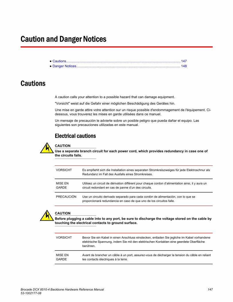
Caution and Danger Notices
● Cautions........................................................................................................................ 147● Danger Notices............................................................................................................. 148
Cautions
A caution calls your attention to a possible hazard that can damage equipment.
"Vorsicht" weist auf die Gefahr einer möglichen Beschädigung des Gerätes hin.
Une mise en garde attire votre attention sur un risque possible d'endommagement de l'équipement. Ci-dessous, vous trouverez les mises en garde utilisées dans ce manuel.
Un mensaje de precaución le advierte sobre un posible peligro que pueda dañar el equipo. Lassiguientes son precauciones utilizadas en este manual.
Electrical cautionsCAUTIONUse a separate branch circuit for each power cord, which provides redundancy in case one ofthe circuits fails.
VORSICHT Es empfiehlt sich die Installation eines separaten Stromkreiszweiges für jede Elektroschnur alsRedundanz im Fall des Ausfalls eines Stromkreises.
MISE ENGARDE
Utilisez un circuit de dérivation différent pour chaque cordon d’alimentation ainsi, il y aura uncircuit redondant en cas de panne d’un des circuits.
PRECAUCIÓN Use un circuito derivado separado para cada cordón de alimentación, con lo que seproporcionará redundancia en caso de que uno de los circuitos falle.
CAUTIONBefore plugging a cable into to any port, be sure to discharge the voltage stored on the cable bytouching the electrical contacts to ground surface.
VORSICHT Bevor Sie ein Kabel in einen Anschluss einstecken, entladen Sie jegliche im Kabel vorhandeneelektrische Spannung, indem Sie mit den elektrischen Kontakten eine geerdete Oberflächeberühren.
MISE ENGARDE
Avant de brancher un câble à un port, assurez-vous de décharger la tension du câble en reliantles contacts électriques à la terre.
Brocade DCX 8510-4 Backbone Hardware Reference Manual 14753-1002177-08

PRECAUCIÓN Antes de conectar un cable en cualquier puerto, asegúrese de descargar la tensión acumuladaen el cable tocando la superficie de conexión a tierra con los contactos eléctricos.
CAUTIONStatic electricity can damage the chassis and other electronic devices. To avoid damage, keepstatic-sensitive devices in their static-protective packages until you are ready to install them.
VORSICHT Statische Elektrizität kann das System und andere elektronische Geräte beschädigen. UmSchäden zu vermeiden, entnehmen Sie elektrostatisch empfindliche Geräte erst aus derenantistatischer Schutzhülle, wenn Sie bereit für den Einbau sind.
MISE ENGARDE
L'électricité statique peut endommager le châssis et les autres appareils électroniques. Pouréviter tout dommage, conservez les appareils sensibles à l'électricité statique dans leuremballage protecteur tant qu'ils n'ont pas été installés.
PRECAUCIÓN La electricidad estática puede dañar el chasis y otros dispositivos electrónicos. A fin deimpedir que se produzcan daños, conserve los dispositivos susceptibles de dañarse con laelectricidad estática dentro de los paquetes protectores hasta que esté listo para instalarlos.
CAUTIONIf you do not install a module or a power supply in a slot, you must keep the slot filler panel inplace. If you run the chassis with an uncovered slot, the system will overheat.
VORSICHT Falls kein Modul oder Netzteil im Steckplatz installiert wird, muss die Steckplatztafelangebracht werden. Wenn ein Steckplatz nicht abgedeckt wird, läuft das System heiß.
MISE ENGARDE
Si vous n’installez pas de module ou de bloc d'alimentation dans un slot, vous devez laisser lepanneau du slot en place. Si vous faites fonctionner le châssis avec un slot découvert, lesystème surchauffera.
PRECAUCIÓN Si no instala un módulo o un fuente de alimentación en la ranura, deberá mantener el panelde ranuras en su lugar. Si pone en funcionamiento el chasis con una ranura descubierta, elsistema sufrirá sobrecalentamiento.
Danger Notices
A danger notification calls your attention to a possible hazard that can cause injury or death. Thefollowing are the warnings used in this manual.
"Gefahr" weist auf eine mögliche Gefährdung hin, die zu Verletzungen oder Tod führen können. Siefinden die folgenden Warnhinweise in diesem Handbuch.
Un danger attire votre attention sur un risque possible de blessure ou de décès. Ci-dessous, voustrouverez les avertissements utilisés dans ce manuel.
Una señal de peligro le llama la atención sobre cualquier posible peligro que pueda ocasionar dañospersonales o la muerte. A continuación se dan las advertencias utilizadas en este manual.
Danger Notices
148 Brocade DCX 8510-4 Backbone Hardware Reference Manual53-1002177-08

Electrical dangersDANGERMake sure that the power source circuits are properly grounded, then use the power cordsupplied with the device to connect it to the power source.
GEFAHR Stellen Sie sicher, dass die Stromkreise ordnungsgemäß geerdet sind. Benutzen Sie dann dasmit dem Gerät gelieferte Stromkabel, um es an die Srromquelle anzuschließen.
DANGER Vérifiez que les circuits de sources d'alimentation sont bien mis à la terre, puis utilisez lecordond'alimentation fourni avec le dispositif pour le connecter à la source d'alimentation.
PELIGRO Verifique que circuitos de la fuente de corriente están conectados a tierra correctamente; luegouse el cordón de potencia suministrado con el instrumento para conectarlo a la fuente decorriente
DANGERFor safety reasons, the ESD wrist strap should contain a series 1 megaohm resistor.
GEFAHR Aus Sicherheitsgründen sollte ein EGB-Armband zum Schutz von elektronischen gefährdetenBauelementen mit einem 1 Megaohm-Reihenwiderstand ausgestattet sein.
DANGER Pour des raisons de sécurité, la dragonne ESD doit contenir une résistance de série 1 mégaohm.
PELIGRO Por razones de seguridad, la correa de muñeca ESD deberá contener un resistor en serie de 1mega ohmio.
DANGERRemove both power cords before servicing.
GEFAHR Trennen Sie beide Netzkabel, bevor Sie Wartungsarbeiten durchführen.
DANGER Retirez les deux cordons d'alimentation avant toute maintenance.
PELIGRO Desconecte ambos cables de alimentación antes de realizar reparaciones.
DANGERDisconnect the power cord from all power sources to completely remove power from the device.
GEFAHR Ziehen Sie das Stromkabel aus allen Stromquellen, um sicherzustellen, dass dem Gerät keinStrom zugeführt wird.
DANGER Débranchez le cordon d'alimentation de toutes les sources d'alimentation pour coupercomplètement l'alimentation du dispositif.
Caution and Danger Notices
Brocade DCX 8510-4 Backbone Hardware Reference Manual 14953-1002177-08

PELIGRO Para desconectar completamente la corriente del instrumento, desconecte el cordón decorriente de todas las fuentes de corriente.
DANGERIf the installation requires a different power cord than the one supplied with the device, makesure you use a power cord displaying the mark of the safety agency that defines theregulations for power cords in your country. The mark is your assurance that the power cordcan be used safely with the device.
GEFAHR Falls für die Installation ein anderes Stromkabel erforderlich ist (wenn das mit dem Gerätgelieferte Kabel nicht passt), müssen Sie sicherstellen, dass Sie ein Stromkabel mit demSiegel einer Sicherheitsbehörde verwenden, die für die Zertifizierung von Stromkabeln inIhrem Land zuständig ist. Das Siegel ist Ihre Garantie, dass das Stromkabel sicher mit IhremGerät verwendet werden kann.
DANGER Si l'installation nécessite un cordon d'alimentation autre que celui fourni avec le dispositif,assurez-vous d'utiliser un cordon d'alimentation portant la marque de l'organisationresponsable de la sécurité qui définit les normes et régulations pour les cordons d'alimentationdans votre pays. Cette marque vous assure que vous pouvez utiliser le cordon d'alimentationavec le dispositif en toute sécurité.
PELIGRO Si la instalación requiere un cordón de corriente distinto al que se ha suministrado con elinstrumento, verifique que usa un cordón de corriente que venga con la marca de la agenciade seguridad que defina las regulaciones para cordones de corriente en su país. Esta marcaserá su garantía de que el cordón de corriente puede ser utilizado con seguridad con elinstrumento.
Dangers related to equipment weightDANGERUse safe lifting practices when moving the product.
GEFAHR Beim Bewegen des Produktes ist auf eine sichere Hubtechnik zu achten.
DANGER Utiliser des techniques de levage sûres pour déplacer le produit.
PELIGRO Tenga mucho cuidado al levantar el producto para moverlo
DANGERA fully populated Brocade DCX 8510-4 (four FC16-64 port cards, 256 ports) weighsapproximately 69 kg (152 lbs) and requires a hydraulic or assisted lift to install it.
GEFAHR Ein vollständig bestückter Brocade DCX 8510-4 (vier FC16-64-Port-Karten, 256 Ports) wiegtetwa 69 kg und erfordert zur Installation eine hydraulische oder Servo-Hebevorrichtung.
Caution and Danger Notices
150 Brocade DCX 8510-4 Backbone Hardware Reference Manual53-1002177-08

DANGER Un commutateur Brocade DCX 8510-4 complet (quatre cartes de port FC16-64, 256 ports)pèse environ 69 kg et requiert un dispositif de levage hydraulique ou électrique pourl'installation.
PELIGRO Un Brocade DCX 8510-4 con la configuración completa (cuatro tarjetas para puertosFC16-64, 256 puertos) pesa aproximadamente 69 kg (152 libras) y requiere un elevadorhidráulico o asistido para realizar su instalación.
Caution and Danger Notices
Brocade DCX 8510-4 Backbone Hardware Reference Manual 15153-1002177-08

Danger Notices
152 Brocade DCX 8510-4 Backbone Hardware Reference Manual53-1002177-08

Index
10 GbE ports 115
Aapplication blade
determining status 52replacing 68
Bbackbone configuration 35back up configuration 47bezel, WWN, replacing 87blade
CP, LEDs 58FS8-18 115FX8-24 115port, LEDs 52
bladesapplication, replacing 68CR, LEDs 60encryption, replacing 68port, replacing 68support for 13
blower assemblyLEDs 62replacing 86status 62
boot results, interpreting 120BSMI statement (Taiwan) 130
Ccable management fingers, replacing 67cables
attach SFP 43for FC8-64 30managing 46QSFP 33, 46, 96
Canadian requirement 131certifications 129, 131CE statement 130chassis, replacing 101chassis door, replacing 66chassis hardware components 14chassis name, customizing 40chassisName command 40China RoHS 132command
chassisName 40configShow 47configUpload 47configUpload -vf 47configure 40, 43date 41fabricShow 40, 44, 47frureplace 88ipaddrSet 38ipaddrSet -chassis 38ipaddrSet -cp0 38ipaddrSet -cp1 38ipAddrShow 38, 47licenseIdShow 43licenseShow 43, 47logout 39slotShow 52switchDisable 40switchEnable 40switchName 40switchShow 44, 47switchShow -qsfp 45sysShutdown 48tsClockServer 42tsTimeZone 41usbStorage 47
compliance, environmental regulation 132configShow command 47configUpload command 47configUpload -vf command 47configuration, backbone 35configuration backup 47configuration data
Brocade DCX 8510-4 Backbone Hardware Reference Manual 15353-1002177-08

troubleshooting 122configure command 40, 43configuring IP address 38core switch blade
determining status 60replacing 83
CP bladedetermining status 58replacing 73troubleshooting 122verifying operation 78
CR bladedetermining status 82removing 82replacing 81
customizingchassis name 40switch name 40
Ddate, setting 41date command 41diagnostics
boot results 120POST 120
diagnostic tests 121domain ID
setting 40domain IDs
troubleshooting 122
Eencryption blade 115encryption blade, replacing 68environmental regulation compliance 132error messages, WWN card 63Ethernet, establish connection 39Ethernet link speed
troubleshooting 122extension blade 115
FfabricShow command 40, 44, 47FC8-64
qualified cables 30FCC warning (US only) 129FCIP 115FC trunking groups 115features, software 20Fibre Channel Routing Services 115field-replaceable units
See FRUs 14filler panel, replacing 72firmwaredownload
from USB 79frureplace command 88FRUs
application bladereplacing 68
blower assemblyLEDs 62replacing 86
cable management fingers, replacing 67chassis
replacing 101chassis door
replacing 66CP blade
LEDs 58replacing 73
CR bladeLEDs 60replacing 81
encryption bladereplacing 68
filler panel, replacing 72port blade
LEDs 52replacing 68
power supplyLEDs 61replacing 84
QSFP cablesreplacing 96
SFP 43transceivers, replacing 91troubleshooting 122WWN bezel
replacing 87WWN card
replacing 87FS8-18 blade 115FX8-24 blade 115
GGbE ports 115
154 Brocade DCX 8510-4 Backbone Hardware Reference Manual53-1002177-08

Hhigh availability 19
Iinstallation
items required 24SFP 43
installation tasks 23installed licenses 43inter-chassis linking (ICL) See QSFP cables\ 96inter-chassis linking (QSFP) 33, 46, 96IP address, configuring 38ipaddrSet -chassis command 38ipaddrSet command 38ipaddrSet -cp0 command 38ipaddrSet -cp1 command 38ipAddrShow command 38, 47
KKCC statement (Republic of Korea) 129
LLEDs
blower assembly 62CP blade 58CR blade 60port blade 52power supply 61troubleshooting 122
license, chassis software 43licenseIdShow command 43licenseShow command 43, 47local time, synchronizing 42logout command 39
Mmanageability, network 21managing cables 46
NNTP server, external 42numbering, port 27
PPID mode 43port
numbering 27numbering template 125
port bladedetermining status 52replacing 68troubleshooting 122
port identifier mode 43POST, interpreting 120power, providing 27power supply
LEDs 61replacing 84status 61
QQSFP cables
installing 96replacing 96
QSFPsas inter-chassis links 45
QSFP transceivers 96
Rrack space requirement 24regulatory compliance 129reliability, features 19removal and replacement procedure
See RRP 65RRP
application blade 68blade filler panel 72blower assembly 86chassis 101chassis door 66CP blade 73CR blade 81encryption blade 68port blade 68power supply 84QSFP cables 96transceivers 91vertical cable management fingers 67WWN bezel 87WWN card 87
Brocade DCX 8510-4 Backbone Hardware Reference Manual 15553-1002177-08

Ssafety guidelines 24security 20serial connection
establishing 36troubleshooting 122
serial port logout 39serviceability, features 19setting
time zone 41SFPs 43site planning 24slotShow command 52software features 20status
application blade 52blower assembly 62core switch blade 60CP blade 58port blade 52power supply 61WWN card 63
switchconnect to 37domain ID 40
switchDisable command 40switchEnable command 40switch name
customizing 40length 40
switchName command 40switchShow command 44, 47switchShow -qsfp command 45sysShutdown command 48
Ttasks, installation 23template, port numbering 125terminal emulator, configuring 36tool, extraction, transceivers 91transceivers
extraction tool 91QSFP 96replacing 91supported types 26
troubleshooting
chassis power 122configuration data 122CP blade 122domain IDs 122Ethernet link speed 122FRUs 122general 119IP addresses 122LEDs 122port blade 122serial connection 122
trunking groups 115tsClockServer command 42tsTimeZone command 41
UusbStorage command 47
VVCCI statement 129verifying, CP blade operation 78
WWWN bezel
replacing 87WWN card
determining status 63error messages 63preparing for replacement 88replacing 87verifying need to replace 88
156 Brocade DCX 8510-4 Backbone Hardware Reference Manual53-1002177-08