Embed Size (px)
Citation preview

HARDWARE INSTALLATION GUIDE
Brocade DCX BackboneHardware Installation Guide
53-1000685-2428 February 2017

© 2017, Brocade Communications Systems, Inc. All Rights Reserved.
Brocade, the B-wing symbol, and MyBrocade are registered trademarks of Brocade Communications Systems, Inc., in the United States and in othercountries. Other brands, product names, or service names mentioned of Brocade Communications Systems, Inc. are listed at www.brocade.com/en/legal/brocade-Legal-intellectual-property/brocade-legal-trademarks.html. Other marks may belong to third parties.
Notice: This document is for informational purposes only and does not set forth any warranty, expressed or implied, concerning any equipment,equipment feature, or service offered or to be offered by Brocade. Brocade reserves the right to make changes to this document at any time, withoutnotice, and assumes no responsibility for its use. This informational document describes features that may not be currently available. Contact a Brocadesales office for information on feature and product availability. Export of technical data contained in this document may require an export license from theUnited States government.
The authors and Brocade Communications Systems, Inc. assume no liability or responsibility to any person or entity with respect to the accuracy of thisdocument or any loss, cost, liability, or damages arising from the information contained herein or the computer programs that accompany it.
The product described by this document may contain open source software covered by the GNU General Public License or other open source licenseagreements. To find out which open source software is included in Brocade products, view the licensing terms applicable to the open source software, andobtain a copy of the programming source code, please visit http://www.brocade.com/support/oscd.
Brocade DCX Backbone Hardware Installation Guide2 53-1000685-24

ContentsPreface...................................................................................................................................................................................................................................9
Document conventions............................................................................................................................................................................................................................9Notes, cautions, and warnings.....................................................................................................................................................................................................9Text formatting conventions......................................................................................................................................................................................................... 9Command syntax conventions.................................................................................................................................................................................................10
Brocade resources..................................................................................................................................................................................................................................10Document feedback.............................................................................................................................................................................................................................. 10Contacting Brocade Technical Support......................................................................................................................................................................................... 11
Brocade customers.......................................................................................................................................................................................................................11Brocade OEM customers.......................................................................................................................................................................................................... 11
About This Document..................................................................................................................................................................................................... 13Supported hardware and software...................................................................................................................................................................................................13What’s new in this document............................................................................................................................................................................................................. 13
Overview.............................................................................................................................................................................................................................15Brocade DCX features.......................................................................................................................................................................................................................... 15Hardware components..........................................................................................................................................................................................................................15
Port side of the Brocade DCX..................................................................................................................................................................................................17Nonport side of the Brocade DCX......................................................................................................................................................................................... 18
Brocade DCX blades............................................................................................................................................................................................................................. 18Chassis slots............................................................................................................................................................................................................................................. 20Port numbering........................................................................................................................................................................................................................................20High availability........................................................................................................................................................................................................................................ 20Reliability.....................................................................................................................................................................................................................................................21Serviceability............................................................................................................................................................................................................................................. 21Software features.....................................................................................................................................................................................................................................22Security........................................................................................................................................................................................................................................................22Network manageability......................................................................................................................................................................................................................... 23
Preparing for the Installation..........................................................................................................................................................................................25Installation and safety considerations.............................................................................................................................................................................................25Time and items required for installation.........................................................................................................................................................................................26Items included with the device...........................................................................................................................................................................................................27
Mounting the Device........................................................................................................................................................................................................29Mounting precautions............................................................................................................................................................................................................................29Mounting options.................................................................................................................................................................................................................................... 30Unpacking, transporting, and installing the device....................................................................................................................................................................30Installing the 14U Rack Mount Kit for Four-Post Racks (XBR-DCX-0120 and XBR-DCX-0152) ..................................................................31
Time and items required.............................................................................................................................................................................................................32Parts list............................................................................................................................................................................................................................................. 32Parts list – NEBS kit..................................................................................................................................................................................................................... 33Assembling the rack hardware................................................................................................................................................................................................. 34Installing the device in the rack................................................................................................................................................................................................ 37
Installing the 14U Chassis Mid-Mount Rack Kit for Two-Post Racks (XBR-DCX-0121)...................................................................................... 39Time and Items required.............................................................................................................................................................................................................40Parts list............................................................................................................................................................................................................................................. 40
Brocade DCX Backbone Hardware Installation Guide53-1000685-24 3

Assembling the rack hardware................................................................................................................................................................................................. 41Installing the device in the rack................................................................................................................................................................................................ 43
Cable Management.......................................................................................................................................................................................................... 47Requirements and precautions..........................................................................................................................................................................................................47Qualified cables for the FC8-64 port blade................................................................................................................................................................................48Installing ICL cables (optional)........................................................................................................................................................................................................... 49
Logging In and Configuring the DCX Backbone....................................................................................................................................................... 51Items required...........................................................................................................................................................................................................................................51Providing power to the DCX Backbone.........................................................................................................................................................................................52Configuring the Brocade DCX...........................................................................................................................................................................................................52Establishing a serial connection and logging on to the Brocade DCX............................................................................................................................. 53Logging in to the serial console port...............................................................................................................................................................................................54Configuring the IP addresses.............................................................................................................................................................................................................54Logging off the serial console port and disconnecting the serial cable............................................................................................................................56Connecting an Ethernet cable and opening a Telnet session...............................................................................................................................................56Customizing a switch name................................................................................................................................................................................................................56Customizing a chassis name..............................................................................................................................................................................................................57Setting the domain ID........................................................................................................................................................................................................................... 57Setting the date and time.....................................................................................................................................................................................................................57
Setting the date...............................................................................................................................................................................................................................57Setting the time zone................................................................................................................................................................................................................... 58Synchronizing local time.............................................................................................................................................................................................................59
Verifying the PID mode and connecting to the fabric..............................................................................................................................................................59Software licenses.....................................................................................................................................................................................................................................59Installing transceivers and attaching cables................................................................................................................................................................................. 60Managing cables..................................................................................................................................................................................................................................... 60Verifying correct operation and backing up the configuration..............................................................................................................................................61Powering off the Brocade DCX.........................................................................................................................................................................................................62
Monitoring System Components.................................................................................................................................................................................. 63Monitoring overview...............................................................................................................................................................................................................................63Determining the status of a port, application, or encryption blade.....................................................................................................................................63Determining the status of a control processor blade (CP8).................................................................................................................................................. 72Determining the status of a core switch blade (CR8)...............................................................................................................................................................74Determining the status of a power supply....................................................................................................................................................................................76Determining the status of a blower assembly.............................................................................................................................................................................77Determining the status of a WWN card.........................................................................................................................................................................................80
Removal and Replacement Procedures.......................................................................................................................................................................83Introduction................................................................................................................................................................................................................................................83Removal and replacement of the chassis door.......................................................................................................................................................................... 83
Time and items required.............................................................................................................................................................................................................83Removing a chassis door...........................................................................................................................................................................................................83Replacing a chassis door............................................................................................................................................................................................................84
Removal and replacement of the cable management comb................................................................................................................................................84Time and items required.............................................................................................................................................................................................................85Removing a cable management comb................................................................................................................................................................................ 85Replacing a cable management comb.................................................................................................................................................................................86
Removal and replacement of the port, application, and encryption blades....................................................................................................................86Time and items required.............................................................................................................................................................................................................86
Brocade DCX Backbone Hardware Installation Guide4 53-1000685-24

Removing a blade..........................................................................................................................................................................................................................87Replacing a blade...........................................................................................................................................................................................................................88
Removal and replacement of the blade filler panel...................................................................................................................................................................89Removing a filler panel................................................................................................................................................................................................................89Replacing a filler panel.................................................................................................................................................................................................................90
Removal and replacement of the control processor blade (CP8).......................................................................................................................................91Time and items required.............................................................................................................................................................................................................91Verifying the necessity of replacement.................................................................................................................................................................................91Recording critical Brocade DCX information..................................................................................................................................................................... 92Power-up procedure.....................................................................................................................................................................................................................92Power-down procedure...............................................................................................................................................................................................................94Verifying operation of the new CP blade............................................................................................................................................................................. 95
Removal and replacement of the core switch blade (CR8)....................................................................................................................................................97Time and items required.............................................................................................................................................................................................................97Verifying the necessity of replacement.................................................................................................................................................................................97Removing a core switch blade (CR8).................................................................................................................................................................................... 98Replacing a core switch blade (CR8)..................................................................................................................................................................................... 99
Removal and replacement of the power supply......................................................................................................................................................................100Time and items required..........................................................................................................................................................................................................100Identifying power supplies...................................................................................................................................................................................................... 100Power-cord notice...................................................................................................................................................................................................................... 101Removing a power supply...................................................................................................................................................................................................... 101Replacing a power supply....................................................................................................................................................................................................... 102
Removal and replacement of the blower assembly...............................................................................................................................................................103Time and items required..........................................................................................................................................................................................................103Removing a blower assembly ..............................................................................................................................................................................................103Replacing a blower assembly................................................................................................................................................................................................104
WWN card removal and replacement..........................................................................................................................................................................................105Time and items required..........................................................................................................................................................................................................105Using the wwnrecover utility...................................................................................................................................................................................................106Verifying the need for replacement..................................................................................................................................................................................... 106Preparing for WWN card replacement...............................................................................................................................................................................107Hot-swap replacement.............................................................................................................................................................................................................107Power-down replacement.......................................................................................................................................................................................................108Removing the WWN card and WWN bezel (logo plate).............................................................................................................................................110
Removal and replacement of the transceivers.........................................................................................................................................................................113Time Required..............................................................................................................................................................................................................................113Items Required.............................................................................................................................................................................................................................113Removing and replacing an SFP, SFP+, or XFP optical transceiver.....................................................................................................................113Removing and replacing an mSFP optical transceiver...............................................................................................................................................114
Removal and replacement of the inter-chassis link (ICL) cables......................................................................................................................................115Time and items Required........................................................................................................................................................................................................ 116Removing an ICL cable............................................................................................................................................................................................................116Replacing an ICL cable.............................................................................................................................................................................................................117
Removal and replacement of the Brocade DCX chassis.................................................................................................................................................... 125Time and items required..........................................................................................................................................................................................................125Verifying need for replacement.............................................................................................................................................................................................125Recording critical Brocade DCX and SAN information.............................................................................................................................................. 126Disconnecting from network and fabric............................................................................................................................................................................ 129Removing components from the chassis.........................................................................................................................................................................130
Brocade DCX Backbone Hardware Installation Guide53-1000685-24 5

Installing the replacement chassis....................................................................................................................................................................................... 130Installing components into the new chassis.................................................................................................................................................................... 131Downloading the configuration.............................................................................................................................................................................................132Verifying correct operation of system................................................................................................................................................................................ 132Reconnecting the system to the network and fabric....................................................................................................................................................134Verifying correct configuration of the fabric.....................................................................................................................................................................135Cable routing table..................................................................................................................................................................................................................... 135
Application and Encryption Blades............................................................................................................................................................................139Introduction.............................................................................................................................................................................................................................................139FS8-18 blade....................................................................................................................................................................................................................................... 139FX8-24 blade....................................................................................................................................................................................................................................... 139FCOE10-24 blade.............................................................................................................................................................................................................................141
Diagnostics and Troubleshooting...............................................................................................................................................................................143Introduction.............................................................................................................................................................................................................................................143Obtaining chassis and component status................................................................................................................................................................................. 143Interpreting POST and boot results............................................................................................................................................................................................. 144
POST...............................................................................................................................................................................................................................................144Boot..................................................................................................................................................................................................................................................144
Diagnostics............................................................................................................................................................................................................................................. 145Troubleshooting....................................................................................................................................................................................................................................145Powering off the Brocade DCX......................................................................................................................................................................................................147
Port Numbering Template........................................................................................................................................................................................... 149
Regulatory Statements................................................................................................................................................................................................. 157BSMI statement (Taiwan)..................................................................................................................................................................................................................157Canadian requirements......................................................................................................................................................................................................................157CE statement......................................................................................................................................................................................................................................... 157China ROHS.......................................................................................................................................................................................................................................... 158FCC warning (US only)...................................................................................................................................................................................................................... 158KCC statement (Republic of Korea).............................................................................................................................................................................................. 158VCCI statement.....................................................................................................................................................................................................................................158
Brocade DCX Backbone Technical Specifications................................................................................................................................................. 159System specifications.........................................................................................................................................................................................................................159Fibre Channel.........................................................................................................................................................................................................................................159LEDs..........................................................................................................................................................................................................................................................159Other......................................................................................................................................................................................................................................................... 160Weight and physical dimensions................................................................................................................................................................................................... 160Environmental requirements........................................................................................................................................................................................................... 160Power supply specifications (per PSU).......................................................................................................................................................................................160Power consumption (maximum configuration)........................................................................................................................................................................161Data port specifications (Fibre Channel).....................................................................................................................................................................................161Fibre Channel data transmission ranges....................................................................................................................................................................................161Serial port specifications (DB9)..................................................................................................................................................................................................... 162Serial port specifications (pinout mini-USB)............................................................................................................................................................................ 162Serial port specifications (pinout RJ-45)....................................................................................................................................................................................162Serial port specifications (protocol)...............................................................................................................................................................................................163Regulatory compliance (EMC)........................................................................................................................................................................................................163Regulatory compliance (safety)...................................................................................................................................................................................................... 163Regulatory compliance (environmental)..................................................................................................................................................................................... 163
Brocade DCX Backbone Hardware Installation Guide6 53-1000685-24

Caution and Danger Notices....................................................................................................................................................................................... 165Cautions...................................................................................................................................................................................................................................................165Danger notices...................................................................................................................................................................................................................................... 166
Brocade DCX Backbone Hardware Installation Guide53-1000685-24 7

Brocade DCX Backbone Hardware Installation Guide8 53-1000685-24

Preface• Document conventions...................................................................................................................................................................................... 9• Brocade resources............................................................................................................................................................................................ 10• Document feedback.........................................................................................................................................................................................10• Contacting Brocade Technical Support....................................................................................................................................................11
Document conventionsThe document conventions describe text formatting conventions, command syntax conventions, and important notice formats used inBrocade technical documentation.
Notes, cautions, and warningsNotes, cautions, and warning statements may be used in this document. They are listed in the order of increasing severity of potential
hazards.
NOTEA Note provides a tip, guidance, or advice, emphasizes important information, or provides a reference to related information.
ATTENTIONAn Attention statement indicates a stronger note, for example, to alert you when traffic might be interrupted or the device mightreboot.
CAUTIONA Caution statement alerts you to situations that can be potentially hazardous to you or cause damage to hardware,firmware, software, or data.
DANGERA Danger statement indicates conditions or situations that can be potentially lethal or extremely hazardous to you. Safetylabels are also attached directly to products to warn of these conditions or situations.
Text formatting conventionsText formatting conventions such as boldface, italic, or Courier font may be used to highlight specific words or phrases.
Format Description
bold text Identifies command names.
Identifies keywords and operands.
Identifies the names of GUI elements.
Identifies text to enter in the GUI.
italic text Identifies emphasis.
Identifies variables.
Identifies document titles.
Courier font Identifies CLI output.
Brocade DCX Backbone Hardware Installation Guide53-1000685-24 9

Format Description
Identifies command syntax examples.
Command syntax conventionsBold and italic text identify command syntax components. Delimiters and operators define groupings of parameters and their logicalrelationships.
Convention Description
bold text Identifies command names, keywords, and command options.
italic text Identifies a variable.
value In Fibre Channel products, a fixed value provided as input to a command option is printed in plain text, forexample, --show WWN.
[ ] Syntax components displayed within square brackets are optional.
Default responses to system prompts are enclosed in square brackets.
{ x | y | z } A choice of required parameters is enclosed in curly brackets separated by vertical bars. You must selectone of the options.
In Fibre Channel products, square brackets may be used instead for this purpose.
x | y A vertical bar separates mutually exclusive elements.
< > Nonprinting characters, for example, passwords, are enclosed in angle brackets.
... Repeat the previous element, for example, member[member...].
\ Indicates a “soft” line break in command examples. If a backslash separates two lines of a commandinput, enter the entire command at the prompt without the backslash.
Brocade resourcesVisit the Brocade website to locate related documentation for your product and additional Brocade resources.
White papers, data sheets, and the most recent versions of Brocade software and hardware manuals are available at www.brocade.com.Product documentation for all supported releases is available to registered users at MyBrocade.
Click the Support tab and select Document Library to access product documentation on MyBrocade or www.brocade.com. You canlocate documentation by product or by operating system.
Release notes are bundled with software downloads on MyBrocade. Links to software downloads are available on the MyBrocade landingpage and in the Document Library.
Document feedbackQuality is our first concern at Brocade, and we have made every effort to ensure the accuracy and completeness of this document.However, if you find an error or an omission, or you think that a topic needs further development, we want to hear from you. You canprovide feedback in two ways:
• Through the online feedback form in the HTML documents posted on www.brocade.com
• By sending your feedback to [email protected]
Provide the publication title, part number, and as much detail as possible, including the topic heading and page number if applicable, aswell as your suggestions for improvement.
Brocade resources
Brocade DCX Backbone Hardware Installation Guide10 53-1000685-24

Contacting Brocade Technical SupportAs a Brocade customer, you can contact Brocade Technical Support 24x7 online or by telephone. Brocade OEM customers shouldcontact their OEM/solution provider.
Brocade customersFor product support information and the latest information on contacting the Technical Assistance Center, go to www.brocade.com andselect Support.
If you have purchased Brocade product support directly from Brocade, use one of the following methods to contact the BrocadeTechnical Assistance Center 24x7.
Online Telephone
Preferred method of contact for non-urgent issues:
• Case management through the MyBrocade portal.
• Quick Access links to Knowledge Base, Community, DocumentLibrary, Software Downloads and Licensing tools
Required for Sev 1-Critical and Sev 2-High issues:
• Continental US: 1-800-752-8061
• Europe, Middle East, Africa, and Asia Pacific: +800-AT FIBREE(+800 28 34 27 33)
• Toll-free numbers are available in many countries.
• For areas unable to access a toll-free number:+1-408-333-6061
Brocade OEM customersIf you have purchased Brocade product support from a Brocade OEM/solution provider, contact your OEM/solution provider for all ofyour product support needs.
• OEM/solution providers are trained and certified by Brocade to support Brocade® products.
• Brocade provides backline support for issues that cannot be resolved by the OEM/solution provider.
• Brocade Supplemental Support augments your existing OEM support contract, providing direct access to Brocade expertise.For more information, contact Brocade or your OEM.
• For questions regarding service levels and response times, contact your OEM/solution provider.
Contacting Brocade Technical Support
Brocade DCX Backbone Hardware Installation Guide53-1000685-24 11

Brocade DCX Backbone Hardware Installation Guide12 53-1000685-24
About This Document• Supported hardware and software..............................................................................................................................................................13• What’s new in this document........................................................................................................................................................................13
Supported hardware and softwareThis document includes information specific to the Brocade DCX running Brocade Fabric OS version 7.4.0. and later.
Initial support for this device was at Fabric OS version 6.2.0.
What’s new in this documentThe following changes have been made in this document:
• Modified the copyright statement.
• Added note about RTC/NVRAM batteries in Hardware components on page 15.
• Editorial changes to sections in GUID-25F4B3AC-7D35-4DBB-A847-68D335839B41.ditamap.
• Added notes to following sections directing users replacing a defective chassis to not replace WWN cards shipped preinstalledin replacement chassis with existing WWN cards as this will cause licensing and RMA problems. Note also describes licensetransfer process.
– Removing components from the chassis on page 130– Installing components into the new chassis on page 131
• Editorial changes in rack mount kit procedures.
Brocade DCX Backbone Hardware Installation Guide53-1000685-24 13

Brocade DCX Backbone Hardware Installation Guide14 53-1000685-24

Overview• Brocade DCX features.....................................................................................................................................................................................15• Hardware components.................................................................................................................................................................................... 15• Brocade DCX blades........................................................................................................................................................................................18• Chassis slots........................................................................................................................................................................................................20• Port numbering.................................................................................................................................................................................................. 20• High availability...................................................................................................................................................................................................20• Reliability................................................................................................................................................................................................................21• Serviceability........................................................................................................................................................................................................21• Software features............................................................................................................................................................................................... 22• Security.................................................................................................................................................................................................................. 22• Network manageability....................................................................................................................................................................................23
Brocade DCX featuresThe Brocade DCX represents the next generation of advanced Fibre Channel enterprise-class platforms used to intelligently interconnectstorage devices, hosts, and servers in a Storage Area Network (SAN). The Brocade DCX is the highest-performance and highest-scalability enterprise-class platform offered by Brocade. It satisfies the most demanding Reliability, Availability, and Serviceability (RAS),performance, and scalability requirements, while delivering investment protection, interoperability, and fabric-based intelligenceadvantages found only in the Brocade product family.
Key features of the Brocade DCX include:
• Up to 512 external ports in a single chassis, enabling high density SAN configurations with reduced footprint.
• Support for 1-, 2-, 4-, and 8-Gbps auto-sensing Fibre Channel (FC) ports. Trunking technology groups up to eight ports tocreate high performance 64-Gbps ISL trunks between switches. (10-Gbps ports (FC10-6) are 10 Gbps only.)
• Up to 1024 ports in the same rack can connect with the use of inter-chassis links (ICLs). Up 1536 ports can be connected viaICLs in adjacent racks.
• Support for high-performance port blades running at 1, 2, 4, 8, or 10 Gbps, enabling flexible system configuration.
• Redundant and hot-swappable CP8 and CR8 blades, power supplies, blower assemblies, and WWN cards that enable a highavailability platform and enable nondisruptive software upgrades for mission-critical SAN applications.
• Universal ports that self-configure as E_Ports, F_Ports, FL_Ports, Ex_Ports and M_Ports (mirror ports). (10-Gbps ports(FC10-6) are E_Ports only.)
• Data cryptographic (encryption/decryption) and data compression capabilities through the Brocade FS8-18 Encryption Blade.
• Fibre Channel over IP (FCIP) functionality through the FX8-24 blade.
• Fibre Channel over Ethernet (FCoE) capability through the FCOE10-24 blade.
Hardware componentsThe Brocade DCX features a modular and scalable mechanical construction that allows a wide range of flexibility in installation, fabricdesign, and maintenance. The chassis can be mounted with the cables facing the front of the equipment rack or to the rear, and consistsof the following:
• Up to eight hot-swappable port blade assemblies that can be configured in a single chassis, delivering up to 512 Fibre Channelports.
Brocade DCX Backbone Hardware Installation Guide53-1000685-24 15

• Two slots for control processor blades (CP8):
– A single active CP8 blade can control all 512 ports in the chassis.– The standby CP8 blade assumes control of the Brocade DCX if the active CP fails.
NOTEDevice control processors and management modules contain batteries for RTC/NVRAM backup. Do not attempt toreplace these batteries. Dispose of hardware components containing these batteries as required by local ordinancesand regulations.
• Two slots for core switch blades (CR8):
– CR8 blade interconnects all port blades.– Two inter-chassis link (ICL) connectors per blade to connect to another chassis.– Both CR8 blades are active.
• Modular hot-swappable port blades:
– 16-port, 8-Gbps blades (FC8-16)– 32-port, 8-Gbps blades (FC8-32)– 48-port, 8-Gbps blades (FC8-48)– 64-port, 8-Gbps blades (FC8-64)
• Modular hot-swappable application blades:
– FX8-24: 24-port (12 FC, 10 GbE, 2 10GbE) FCIP extension blade enabling long distance communication over existingIP infrastructure.
– FCOE10-24: 24-port (24 10GbE) CEE-based FCoE blade enabling enhanced connectivity using existing Ethernetinfrastructure. This blade cannot be used in the same chassis as the high density port blade FC8-64 or any of the otherapplication blades (FX8-24 or FS8-18).
• Modular hot-swappable encryption blades:
– FS8-18: 16-port, up to 4 blades per chassis, supporting data cryptographic (encryption/decryption) and data-compression capabilities.
• Modular hot-swappable field-replaceable units (FRUs):
– Three blower assemblies.– Up to four power supplies (100-240 VAC auto-sensing).
› At 240 VAC: A minimum of two power supplies is required, regardless of the number of port or application blades.240 VAC is recommended for efficiency and high availability.
› At 120 VAC: Four power supplies are required when using the FS8-18, FX8-24, or FCOE10-24 blades.› Redundant AC primary power connections to ensure high availability. Each power supply has its own connector, so the
number of primary power connections varies from two (recommended minimum) to four (optimum efficiency andredundancy).
– Two WWN cards.– Small Form-factor Pluggable (SFP, SFP+, and mSFP) optical transceivers. SFP transceivers support speeds of 1, 2, and 4
Gbps. SFP+ and mSFP transceivers support speeds of 2, 4, and 8 Gbps.– Extended Form-factor Pluggable (XFP) optical transceivers (10 Gbps).
NOTEThe 8-Gbps SFPs and mSFPs auto-negotiate at 2, 4, and 8 Gbps. The 4-Gbps SFPs auto-negotiate at 1, 2, and 4 Gbps.
• Blades that are serviced from the port side of the Brocade DCX. Blowers, power supplies, and power cables that are servicedfrom the nonport side.
Hardware components
Brocade DCX Backbone Hardware Installation Guide16 53-1000685-24

• World Wide Name (WWN) cards on the nonport side, to maintain chassis-specific information such as WWNs, IP addresses,and summary status information of each port blade and power supply through LEDs.
• Redesigned cable management comb and chassis door.
• Constant intake and FRU temperature monitoring.
Port side of the Brocade DCXNOTEAirflow in the Brocade DCX is from the nonport (noncable) side to the port (cable) side and out the exhaustvent.
The following illustration displays a sample configuration of the port side of the Brocade DCX.
FIGURE 1 Port side of the Brocade DCX (sample configuration)
1. Exhaust Vent
2. Core switch blade (CR8)
3. Control processor blade (CP8)
Hardware components
Brocade DCX Backbone Hardware Installation Guide53-1000685-24 17

4. FC8-48 port blade
5. Cable management comb
Nonport side of the Brocade DCXThe following illustration displays a sample configuration of the nonport side of the Brocade DCX.
FIGURE 2 Nonport side of the Brocade DCX (sample configuration)
1. WWN bezel (logo plate)
2. Power supply (4x)
3. Blower assembly (3x)
Brocade DCX bladesThe following table summarizes the port, application, control processor, and core switch blades that are supported on the Brocade DCX.
Brocade DCX blades
Brocade DCX Backbone Hardware Installation Guide18 53-1000685-24

TABLE 1 Blades supported on Brocade DCX
Description Name Function
Brocade DCX control processor blade CP8 The CP8 blade contains the control plane for thechassis. There are two CP8 blades forredundancy. This control processor blade iscompatible with the Brocade DCX and BrocadeDCX-4S.
Brocade DCX core switch blade CR8 The CR8 blade contains the ASICs for switchingbetween port blades. Every port blade connectsto each core switch blade. There can be up to512 total ports for port blades. Each core switchblade connects to 128 backplane ports. Coreswitch blades have additional front portconnectivity to connect multiple chassis andbackplane connections for the storage serverblade. This core switch blade is compatible onlywith the Brocade DCX.
16-port 8-Gbps port blade FC8-16 A 16-port Brocade port blade supporting 1, 2,4, and 8 Gbps port speeds. This port blade iscompatible with the Brocade 48000 Director,Brocade DCX, and Brocade DCX-4S.
32-port 8-Gbps port blade FC8-32 A 32-port Brocade port blade supporting 1, 2,4, and 8 Gbps port speeds. This port blade iscompatible with the Brocade 48000 Director,Brocade DCX, and Brocade DCX-4S.
48-port 8-Gbps port blade FC8-48 A 48-port Brocade port blade supporting 1, 2,4, and 8 Gbps port speeds. This port blade iscompatible with the Brocade 48000 Director,Brocade DCX, and Brocade DCX-4S.
64-port 8-Gbps port blade FC8-64 A 64-port Brocade port blade supporting 2, 4,and 8 Gbps port speeds. This port blade iscompatible with the Brocade DCX and BrocadeDCX-4S. This blade cannot be used in the samechassis with an FCOE10-24 blade.
Storage encryption blade FS8-18 The FS8-18 blade enables data cryptographic(encryption/decryption) and data-compressioncapabilities. It has 16 Fibre Channel optical SFPports. This application blade is compatible withthe Brocade 48000 Director, Brocade DCX, andBrocade DCX-4S.
FCIP extension blade FX8-24 The FX8-24 blade enables FCIP functionalityover existing IP infrastructure. It has 12 FCports, 10 GbE ports, and 2 10GbE portsavailable. This application blade is compatiblewith the Brocade DCX and Brocade DCX-4S.
Fibre Channel over Ethernet blade FCOE10-24 The FCOE10-24 blade enables FCoEfunctionality over existing Ethernet infrastructureutilizing CEE protocols. It has 24 10GbE portsavailable. This application blade is compatiblewith the Brocade DCX and BrocadeDCX-4S.This blade cannot be used in the samechassis with an FC8-64 high density port bladeor any of the other application blades (FX8-24or FS8-18).
Brocade DCX blades
Brocade DCX Backbone Hardware Installation Guide53-1000685-24 19

Chassis slotsChassis slots are numbered 1 through 12, from left to right when facing the port side of the Brocade DCX. Control processor blades(CP8) can be installed only in slots 6 and 7. Core switch blades (CR8) can be installed only in slots 5 and 8. The rest of the slots ,1-4 and9-12, can be filled with port, application, or encryption blades. Unused slots must be filled with blade filler panels to maintain adequatecooling.
Port numberingThe Brocade DCX uses the following port numbering method (Port Numbering Template on page 149).
Port or application blade Port numbering Trunking port group numbering
FC8-16 port blade • 0 through 15 from bottom to top.
FC8-32 port blade • 0 through 15 from bottom to top on the left set ofports.
• 16 through 31 from bottom to top on the right setof ports.
FC8-48 port blade • 0 through 23 from bottom to top on the left set ofports.
• 24 through 47 from bottom to top on the right setof ports.
FC8-64 port blade • 0 through 31 from bottom to top on the left set ofports.
• 32 through 63 from bottom to top on the right setof ports.
• 0-7, 8-15, 16-23, 24-31, 32-39, 40-47,48-55, and 56-63.
FS8-18 blade • FC ports: 0 through 15 from bottom to top.
• 10/100/1000 BaseT ports: GE0 and GE1 fromthe bottom.
FX8-24 blade • FC ports: 0 through 11 in two vertical rows of sixports starting from the bottom left and bottom rightin the lower group of 12 ports. Labeled as FC onthe front panel diagram.
• 10-GbE ports: 0 and 1 in the left-hand column justabove the FC ports. Labeled as 10GE on the frontpanel diagram.
• 1-GbE ports: 0 through 9 in both columns abovethe FC and 10GE ports. Labeled as GE on thefront panel diagram.
Up to three FC trunking groups are permitted.
• Trunk group 0: FC ports 0, 1
• Trunk group 1: FC ports 6, 7
• Trunk group 2: FC ports 2, 3, 4, 5, 8, 9, 10,11
FCOE10-24 blade • 0 through 23 in two vertical rows from bottom leftto top right.
High availabilityThe following features contribute to the Brocade DCX high-availability design:
• Redundant, hot-swappable blades and FRUs
• Enhanced data integrity on all data paths
• Fabric Shortest Path First (FSPF) rerouting around failed links
Chassis slots
Brocade DCX Backbone Hardware Installation Guide20 53-1000685-24

• Integration with Simple Network Management Protocol (SNMP) managers
• Automatic control processor failover
• Nondisruptive "hot" software code loads and activation
• Easy configuration, save, and restore
• Hot-swappable World Wide Name (WWN) cards
The high-availability software architecture of the Brocade DCX provides a common framework for all applications that reside on thesystem, allowing global and local states to be maintained through any component failure. High-availability elements consist of the HighAvailability Manager, the heartbeat, the fault/health framework, the replicated database, initialization, and software upgrade.
The High Availability Manager controls access to the standby control processor, facilitates software upgrades, prevents extraneousswitchover activity, closes and flushes streams, provides flow control and message buffering, and supports a centralized active andstandby state.
ReliabilityThe Brocade DCX uses the following error detection and correction mechanisms to ensure reliability of data:
• Error Detection and Fault Isolation (EDFI) mechanism, which checks for encoder errors and fault isolation, such as cyclicredundancy checking (CRC), parity checking, checksum, and illegal address checking.
• Power-on self-test (POST).
• Dual control processors that enable hot, nondisruptive fast firmware upgrades.
• One serial port and two Ethernet ports (on each control processor) for management and for service. Offline control processordiagnostics and remote diagnostics simplify troubleshooting. The standby control processor monitors diagnostics to ensure it isoperational, should a failover be necessary.
• Bus monitoring and control of blades and other field-replaceable units (FRUs).
ServiceabilityThe Brocade DCX provides the following features to enhance and ensure serviceability:
• Modular design with hot-swappable components
• Flash memory that stores two firmware images per control processor
• USB port on control processor blades for all tasks that formerly required an FTP/SCP server, including software and firmwareupgrades
• Nonvolatile random-access memory (NVRAM), containing the OEM serial number, Brocade serial number, revision information,and part number information
• Background health-check daemon
• Memory scrubber, self test, and bus ping to determine if a bus is not functioning
• RASlog messages
• SMI-S compliant
• Watchdog timers
• Status LEDs
• Predictive diagnostics analysis through Fabric Watch
Serviceability
Brocade DCX Backbone Hardware Installation Guide53-1000685-24 21

• SNMP (including version 3) integration with higher-layer managers
Software featuresThe Fabric OS allows any Fibre Channel-compliant device to attach to the switches as long as it conforms to the device login, nameservice, and related Fibre Channel standards. Each operating environment requires that a Fibre Channel host bus adapter (HBA) beavailable with a standards-compliant driver for correct interface to the fabric.
Fabric OS consists of a set of embedded applications running on top of an embedded Linux operating system kernel. These applicationsinclude:
• Name server
• Alias server
• Zone server
• Simple Network Management Protocol (SNMP) agent
• SMI-S compliant API
• Syslog auditing
• RCS (Reliable Commit Service)
• NTP
• Tasks to manage address assignment, routing, link initialization, fabric initialization, link shutdown, Brocade DCX shutdown, andthe user interface
SecurityThe following table highlights some of the key security features available for the Brocade DCX and for other Brocade enterprise-classproducts running Fabric OS 5.2.0 or later. For details, contact your Brocade DCX supplier and refer to the Brocade White Paper, "TheGrowing Need for Security in Storage Area Networks".
TABLE 2 Brocade security features
Brocade Security Features Description
DH-CHAP Login banner
SSHv2 (using AES, 3DES, RSA) Monitoring of attempted security breaches (through audit logging)
HTTPS (using AES) Monitoring of attempted security breaches (through Fabric Watch SecurityClass)
SNMPv3 Fibre Channel security policies: DCC and SCC
FC-SP Trusted Switch (FCS) for central security management
Secure RPC Management access controls (SNMPv3, Telnet, FTP, serial port, frontpanel)
Secure file copy (SCP) Hardware-enforced zoning by WWN, domain/port ID, or both
Telnet disable Default zoning
Telnet timeout RSCN suppression and aggregation
IP filters (block listeners) Configurable RSCN suppression by port
Secure passwords (centralized control through RADIUS/CHAP) NTPv3 (to synchronize timestamps)
Up to 255 multiple user accounts (MUAs). Event auditing
Role-based access controls (RBACs) Change tracking
Software features
Brocade DCX Backbone Hardware Installation Guide22 53-1000685-24

TABLE 2 Brocade security features (continued)
Brocade Security Features Description
Administrative domains/Virtual fabrics Firmware change alerts in Fabric Manager
Boot PROM password reset Persistent port disable
Password hardening policies Persistent domain ID
Upfront login in Web Tools E_Port disable
Network manageabilityThe Brocade DCX has a single domain and is managed as a single element with the Data Center Fabric Manager (DCFM). The BrocadeDCX responds to its own IP address and appears as a separate entity to the Telnet protocol and SNMP.
All management interfaces, such as Telnet, Web Tools, standards-compliant SMI-S, and Management Server, support a "port N withinblade M" naming scheme.
The Brocade DCX supports SNMPv1 and SNMPv3. When SNMP devices send SNMP messages to a management console runningSAN management software, the information is stored in a management information base (MIB). Fabric OS v6.1.1_enc and latersupports the latest Fibre Alliance Fibre Channel Management (FCMGMT) and Storage Management Initiative (SMI) MIBs, which allowcommon information necessary for management software to provide information to a SAN administrator. Refer to the Brocade FabricOS Administration Guide for additional MIB information.
Network manageability
Brocade DCX Backbone Hardware Installation Guide53-1000685-24 23

Brocade DCX Backbone Hardware Installation Guide24 53-1000685-24

Preparing for the Installation• Installation and safety considerations........................................................................................................................................................25• Time and items required for installation................................................................................................................................................... 26• Items included with the device..................................................................................................................................................................... 27
Installation and safety considerationsNOTERead the safety notices before installation.
Read the following sections before preparing to install the device.
• Caution and Danger Notices on page 165.
• Brocade DCX Backbone Technical Specifications on page 159, power supply specifications section, and plan for meeting thepower supply standards based on your device configuration.
• Cable Management on page 47 and plan for cable management.
The following steps are required to ensure correct installation and operation:
1. Ensure that dedicated electrical branch circuits with the following characteristics are available:
• 200-240 VAC, 50-60 Hz (two branch circuits)
• 110-120 VAC, 50-60 Hz (up to four branch circuits)
• Two cables for 200-240 VAC service; up to four cables for 110-120 VAC service
• Power supply standards are met
• Protected by a circuit breaker in accordance with local electrical codes
• Supply circuit, line fusing, and wire size adequate to the electrical rating on the chassis nameplate
• Location close to the chassis and easily accessible
• Grounded outlets installed by a licensed electrician and compatible with the power cords
ATTENTIONTo maximize fault tolerance, connect each power cord to a separate power source.
2. Plan for cable management before installing the chassis (Cable Management on page 47).
Cables can be managed in a variety of ways, such as by routing cables below the chassis, to either side of the chassis, throughcable channels on the sides of the cabinet, or by using patch panels.
Brocade DCX Backbone Hardware Installation Guide53-1000685-24 25

3. Ensure that the following is available for configuration of the Brocade DCX:
• Workstation with an installed terminal emulator, such as HyperTerminal
• Serial cable (provided)
• Three Ethernet cables (including one spare)
• Access to an FTP server for backing up the switch configuration or collecting supportsave output data (optional)
• A Brocade USB stick for collecting supportsave output data (optional)
• SFPs and compatible cables
NOTEFor information about the SFP transceivers that are qualified for the Brocade Encryption Switch, go to http://www.brocade.com/products/interop_and_compatibility.jsp.
4. Ensure that the air intake and exhaust vents have a minimum of 2 inches of airspace.
5. Ensure that the air temperature on the air intake side is less than 40 degrees Celsius (104 degrees Fahrenheit) during operation.
Time and items required for installationThe following table describes the main installation and setup tasks, the estimated time required for each, and the items required tocomplete the task based on a fully populated Brocade DCX (512 Fibre Channel ports). Configurations with fewer ports require less time.These time estimates assume a prepared installation site and appropriate power and network connectivity.
TABLE 3 Installation tasks, time, and items required
Installation task Time estimate Items required
Site preparation and unpacking Brocade DCX 30 minutes 1/2-in. socket wrench (to remove pallet bolts).
#2 Phillips screwdriver(for cable managementcomb).
Pallet jack.
Hydraulic lift or assisted lift, able to raise to aminimum of 140 cm (55 in.), with a minimumcapacity of 113 kg (250 lb). The Brocade DCXweighs 159.2 kg (351 lb) with eight FC8-64port blades installed (512 ports).
Installing rack mount kit 30 minutes Refer to Mounting the Device on page 29 .
Mounting and securing Brocade DCX in rack 30 minutes
Installing power cables and powering on theBrocade DCX
20 minutes Power cables.
Establishing serial connection, logging on toBrocade DCX, and configuring IP addresses
20 minutes Serial cable (provided in the accessory kit).
Workstation computer with a serial port orterminal server port and a terminal emulatorapplication (such as HyperTerminal).
Ethernet IP addresses for the Brocade DCX andfor both control processor blades: total threeaddresses.
Installing an Ethernet cable, opening a Telnetsession, and configuring the Brocade DCXdomain ID, date and time, and additional systemparameters. Verify and back up configuration.
20 minutes Ethernet cabling (optional) for Telnet access.
Refer to the Brocade Fabric OS AdministrationGuide.
Time and items required for installation
Brocade DCX Backbone Hardware Installation Guide26 53-1000685-24

TABLE 3 Installation tasks, time, and items required (continued)
Installation task Time estimate Items required
Installing SFP, SFP+, mSFP, and XFP (10-Gbps) optical transceivers as needed
30 minutes SFP, SFP+, mSFP, and XFP (10-Gbps) opticaltransceivers as needed.
Attaching fiber optic cables, cable ties, and cableguides
2-3 hours Fiber optic cables, cable ties, and cable comb.
Items included with the deviceThe Brocade DCX ships with the following:
• Brocade DCX chassis, populated with:
– Control processor blades (CP8)– Core switch blades (CR8)– Port blades and application blades, and encryption blades (included based on customer specification)– Blade slot filler panels (for slots not filled by a port, control processor, or core switch blade)– WWN cards– WWN bezel (logo plate)– Power supplies– Power supply filler panels (included if there are fewer than four power supplies)– Blower assemblies– Cable management comb– Chassis door
• Accessory kit containing the following items:
– ESD grounding strap– USB device– RS-232 serial cable. The RS-232 cable has an adapter at one end that can be removed to provide an RJ-45-style
connector.
• 14U Rack Mount Kit with instructions (includes rear brackets and bottom support rails)
Order the optical transceivers (SFP, SFP+, mSFP, and XFP) from Brocade. The Brocade DCX supports SWL, LWL, and ELWLtransceivers. The mSFPs are SWL transceivers only.
NOTEFor information about the SFP, SFP+, mSFP, and XFP transceivers that are qualified for the Brocade DCX, go to http://www.brocade.com/products/interop_and_compatibility.jsp.
Items included with the device
Brocade DCX Backbone Hardware Installation Guide53-1000685-24 27

Brocade DCX Backbone Hardware Installation Guide28 53-1000685-24

Mounting the Device• Mounting precautions...................................................................................................................................................................................... 29• Mounting options...............................................................................................................................................................................................30• Unpacking, transporting, and installing the device.............................................................................................................................. 30• Installing the 14U Rack Mount Kit for Four-Post Racks (XBR-DCX-0120 and XBR-DCX-0152) ............................ 31• Installing the 14U Chassis Mid-Mount Rack Kit for Two-Post Racks (XBR-DCX-0121).................................................39
Mounting precautionsEnsure that the following amount of space is available in the rack.
NOTE1U is equal to 4.45 cm (1.75 inches).
• 14 rack units (14U) high
• 61.29 cm (24.09 in.) deep
• 43.74 cm (17.22 in.) wide
The following general considerations for mounting the device.
• Review Installation and safety considerations on page 25 before mounting the device and ensure that all facility requirementsare met.
• The device can be installed facing either direction in a cabinet, if serviceability and cooling requirements are met.
• Plan to install the device with the nonport side facing the air-intake aisle. The device can be installed facing either direction, ifserviceability and cooling requirements are met.
• Ensure that the air intake and exhaust vents have a minimum of 5.1 cm (2 in.) of airspace.
• Ensure that the air temperature on the air intake side is less than 40°C (104°F) during operation.
• Use a hydraulic lift or assisted lift that can raise a minimum of 140 cm (55 in.), with a minimum capacity of 115 kg (254 lb).Refer to Brocade DCX Backbone Technical Specifications on page 159 for the weight of your device, fully populated with therequired blades.
CAUTIONDo not use the port cover tabs to lift the module. They are not designed to support the weight of the module, which can falland be damaged.
CAUTIONMake sure the airflow around the front, and back of the device is notrestricted.
DANGERMount the devices you install in a rack as low as possible. Place the heaviest device at the bottom and progressively placelighter devices above.
DANGERUse safe lifting practices when moving the product.
Brocade DCX Backbone Hardware Installation Guide53-1000685-24 29

CAUTIONTo prevent damage to the chassis and components, never attempt to lift the chassis using the fan or power supply handles.These handles were not designed to support the weight of the chassis.
CAUTIONNever leave tools inside the chassis.
DANGERMake sure the rack housing the device is adequately secured to prevent it from becoming unstable or falling over.
Mounting optionsThis device can be installed as a standalone unit on a flat surface or mounted a 19-inch Electronic Industries Association (EIA) or two-post telecommunications (TELCO)equipment rack.
• In a four-post 19 in. (48.3 cm) EIA rack:
– Use the 14U rack mount kit for four-post racks (XBR-DCX-0120), which contains shelf brackets that telescope from 27 in.(68.58 cm) to 31 in. (78.74 cm) to fit the majority of racks.
– Use the 14U rack mount kit for four-post racks (XBR-DCX-0152), which contains 22 in. (55.88 cm) fixed shelf bracketsdesigned for specific racks.
– Refer to Installing the 14U Rack Mount Kit for Four-Post Racks (XBR-DCX-0120 and XBR-DCX-0152) on page 31 forinstructions.
• In a two-post Telco rack:
– Use the 14U mid-mount rack kit for two-post racks (XBR-DCX-0121).– Refer to Installing the 14U Chassis Mid-Mount Rack Kit for Two-Post Racks (XBR-DCX-0121) on page 39 for
instructions.
NOTEReview the Installation and safety considerations on page 25 before mounting the device and ensure that all facilityrequirements are met.
NOTEThe preceding rack mount kits are supported for this device at the publication date of this Hardware Installation Guide. Forcurrent support information, contact your Brocade representative.
Unpacking, transporting, and installing the deviceDANGERUse safe lifting practices when moving the product.
DANGERA fully populated Brocade DCX (eight FC8-64 port cards, 512 ports) weighs approximately 159.2 kg (351 lbs) andrequires a hydraulic or assisted lift to install it.
Mounting options
Brocade DCX Backbone Hardware Installation Guide30 53-1000685-24

Use the following steps to unpack, transport, and install the device.
1. Unpack and install the Brocade DCX.
a) Cut the bands that encircle the packaging.
b) Remove the lid and the kits and foam from the top of the chassis.
c) Lift the cardboard box off the chassis and remove the plastic bag from around the chassis. Save the packing materials foruse when returning the old chassis.
d) Leave the chassis on top of the plastic shipping tray if the chassis must be transported to the installation location.
NOTEThe Brocade DCX packaging does not incorporate a wood pallet and pallet brackets. The chassis sits on top of aplastic shipping tray.
2. Use a pallet jack or other assisted lift to transport the new chassis to the installation area. Doorways must be wider than 91 cm(36 in.) to accommodate the chassis.
3. Remove the 14U Rack Mount Kit, accessory kit, packing foam, and antistatic plastic from the chassis and set aside.
4. Install the rack mount kit in the rack using appropriate instructions in this Hardware Installation Guide.
5. Remove the chassis door from the Brocade DCX.
6. Remove the cable management comb.
7. Use a lift to raise the chassis to the correct level. Follow the instructions provided by the rack kit manufacturer.
8. If applicable, lock the wheels of the lift.
9. Gently slide the chassis onto the final installation surface, ensuring that it remains supported during the transfer.
10. Ensure that the chassis is oriented so that the nonport side has access to intake air (cool).
11. Reinstall the cable management comb.
12. If ICL cables will not be used, ensure that the ICL sockets in the core switch blades have EMI plugs inserted.
13. Reinstall the chassis door.
Installing the 14U Rack Mount Kit for Four-PostRacks (XBR-DCX-0120 and XBR-DCX-0152)Use the following instructions to install a modular device in a 19-in. (48.3 cm) EIA rack using the 14U Rack Mount Kit for Four-PostRacks (XBR-DCX-0120 and XBR-DCX-0152).
Two rack-mount kits are available.
• XBR-DCX-0120 - Contains shelf brackets that telescope from 27 in. (68.58 cm) to 31 in. (78.74 cm) to fit the majority ofracks.
• XBR-DCX-0152 - Contains 22 in. (55.88 cm) fixed shelf brackets that adjust to 27 in. (68.58 cm).
Observe the following when mounting this device:
• Use Electronic Industries Association (EIA) standard racks. Ensure that the space in the 19-in. (48.3 cm) EIA rack is 14U high.
• Verify that the additional weight of the chassis does not exceed the weight limits of the rack.
• Before mounting your device, review any specific installation and facility requirements in this Hardware Installation Guide.
• Hardware devices illustrated in these procedures are only for reference and may not depict the device you are installing into therack.
Installing the 14U Rack Mount Kit for Four-Post Racks (XBR-DCX-0120 and XBR-DCX-0152)
Brocade DCX Backbone Hardware Installation Guide53-1000685-24 31

Time and items requiredAllow approximately one hour to unpack and install a device in a rack.
The following tools are required when installing the 14U Rack Mount Kit for Four-Post Rack:
• Torque screwdriver with #2 Phillips screwdriver tip
• Slotted (flat blade) screwdriver
• Hydraulic or assisted lift with a minimum raise of 140 cm (55 in.) and a minimum capacity of 113 kg (250 lb)
Parts listThe following table lists 14U Rack Mount Kit parts and quantities for different installations. Refer to the illustration following the table toidentify these parts.
TABLE 4 14U rack mount kit parts and quantities
Description Installation Quantity
Left rack mount shelf bracket (rail brackets may differ from ones shown in illustration) All 1
Right rack mount shelf bracket (rail brackets may differ from ones shown in illustration) All 1
10-32 x 5/8 in. (1.58 cm) panhead Phillips screw and washer (torque to 32 in-lb, [37 cm-kg])
All 6
10-32 clip nut For rack rails with round holes 6
1/4-20 x 1/2 in. (1.27 cm) panhead Phillips screw with lock washer (torque to 80 in-lb [92cm-kg])
For rack rails with round holes 16
10-32 retainer nut For rack rails with square holes 6
1/4-20 x 1/2 in. (1.27 cm) panhead Phillips screw with thread locker (torque to 80 in-lb [92cm-kg])
For rack rails with square holes 16
3/8 in. (0.953 cm) alignment washer For rack rails with square holes 16
NOTEDepending on the device and installation, not all the parts may be used on the device type.
Installing the 14U Rack Mount Kit for Four-Post Racks (XBR-DCX-0120 and XBR-DCX-0152)
Brocade DCX Backbone Hardware Installation Guide32 53-1000685-24

FIGURE 3 14U rack kit parts
1. Left rack mount shelf bracket
2. Right rack mount shelf bracket
3. 10-32 x 5/8 in. (1.58 cm) panhead Phillips screw and washer
4. 10-32 clip nut for cabinets that have rails with round holes
5. 1/4-20 x 1/2 in. (1.27 cm) panhead Phillips screw with lock washer forcabinets that have rails with round holes
6. 10-32 retainer nut for cabinets that have rails with square holes
7. 1/4-20 x 1/2 in. (1.27 cm) panhead Phillips screw with thread locker forcabinets that have rails with square holes
8. 3/8 in. (0.953 cm) alignment washer for cabinets that have rails withsquare holes
Parts list – NEBS kitThe following table lists the parts supplied in the XBR-SLX9850-8-NEBS-KIT to help direct airflow away from the rack area. This kit isonly supported for specific devices, and may not apply to the device that you are installing.
NOTEDepending on the device and installation, not all of the parts may be used.
Verify that the items listed in the following figure are included in the NEBS kit.
Installing the 14U Rack Mount Kit for Four-Post Racks (XBR-DCX-0120 and XBR-DCX-0152)
Brocade DCX Backbone Hardware Installation Guide53-1000685-24 33

FIGURE 4 NEBS kit parts list
1. Left cable comb assembly (1)
2. Right cable comb assembly (1)
3. Air filter (1)
4. Chassis door (1)
5. Velcro strap (8)
6. Screw, 10-32 x .63-in., square cone washer (10)
7. Screw, 8-32 x .312 in., flathead (20)
8. Nut retainer (6)
Assembling the rack hardwareAttach the left and right rack mount shelf brackets to the rack rails.
NOTEIf cables are to be routed down through the cable management comb, allow space below the brackets for cable management
1. Locate the shelf brackets in the device.
Installing the 14U Rack Mount Kit for Four-Post Racks (XBR-DCX-0120 and XBR-DCX-0152)
Brocade DCX Backbone Hardware Installation Guide34 53-1000685-24

2. Locate and loosen the screws on the adjustable ends of the brackets (see the following figure) to allow for adjustment to rackdepth.
FIGURE 5 Left and right shelf brackets installed on rails
1. Left rack mount shelf bracket
2. Right rack mount shelf bracket
3. 1/4-20 x 1/2 in. (1.27 cm) panhead Phillips screw with lockwasher for rails with round holes (4 on each end of eachbracket, 16 total)
4. 3/8 in. (0.953 cm) alignment washer for rails with squareholes (4 on each end of each bracket, 16 total)
5. 1/4-20 x 1/2 in. (1.27 cm) panhead Phillips screw withthread locker for rails with square holes (4 on each end of eachbracket, 16 total)
6. Adjustable ends of shelf brackets
7. Intake air direction
8. Exhaust air direction
CAUTIONUse the screws specified in the procedure. Using longer screws can damage thedevice.
Installing the 14U Rack Mount Kit for Four-Post Racks (XBR-DCX-0120 and XBR-DCX-0152)
Brocade DCX Backbone Hardware Installation Guide53-1000685-24 35

3. Position the shelf brackets with the adjustable ends on the intake air aisle side of the rack (see the previous figure).
• For rails with round holes:
– Position the left and right rack mount shelf brackets and attach them to the rack rails. Use eight screws with lockwashers per bracket (four on each end). Tighten the screws to a torque of 80 in-lb (92 cm-kg).
• For rails with square holes:
– Position the left and right rack mount shelf brackets and attach them to the rack rails. Use eight screws and alignmentwashers per bracket (four on each end). Tighten the screws to a torque of 80 in-lb (92 cm-kg).
FIGURE 6 Nut and screw locations for mounting the device
1. 10-32 clip nuts (for round holes)
2. Rail
3. 10-32 retainer nut (for square holes)
4. Rail
5. Top screws in shelf bracket
6. Bottom screws in shelf bracket
7. Left rack mount shelf bracket
8. Right rack mount shelf bracket
9. Hole 1
NOTEStandard EIA rails have holes in sets of three; spaces between the holes are 5/8 in., 5/8 in., and 1/2 in. (1.58 cm,1.58 cm, and 1.27 cm).
4. Tighten the adjusting screws on the sliding portion of the rack mount shelf brackets to a torque of 32 in-lb (37 cm-kg).
Installing the 14U Rack Mount Kit for Four-Post Racks (XBR-DCX-0120 and XBR-DCX-0152)
Brocade DCX Backbone Hardware Installation Guide36 53-1000685-24

5. Attach the clip nuts (for rails with round holes) or retainer nuts (for rails with square holes) to the vertical rails on the exhaust aisleside of the rack (see the previous figure). These clip nuts are used for securing the port side of the device to the rack rails using10-32 x 5/8 inch screws. Use three clips on each rail. Place the clips in optimum locations for securing the device to the rails.
NOTEDo not align the clip or retainer nuts with the top or bottom holes of the mounting bracket because the screw heads willinterfere with the door.
Installing the device in the rackUse the following procedure to install the device in the rack.
DANGERUse safe lifting practices when moving the product.
1. Ensure that the door, if installed, is removed from the port side of the device. For instructions, refer to instructions for removingand replacing the device door in the device installation guide.
2. Use a lift to raise the device to the level of the shelf brackets.
3. Move the lift as close as possible to the rack, with the air-intake side of the device facing the front of the rack (see the followingfigure).
4. If applicable, lock the wheels of the lift.
Installing the 14U Rack Mount Kit for Four-Post Racks (XBR-DCX-0120 and XBR-DCX-0152)
Brocade DCX Backbone Hardware Installation Guide53-1000685-24 37

5. Gently slide the device onto the shelf brackets, ensuring that it remains supported during the transfer.
FIGURE 7 Positioning the device for installation in a rack
1. Rack 2. Nonport side of device
Installing the 14U Rack Mount Kit for Four-Post Racks (XBR-DCX-0120 and XBR-DCX-0152)
Brocade DCX Backbone Hardware Installation Guide38 53-1000685-24

6. Fasten the port side of the device to the rack rails. Use three 10-32 x 5/8 inch (1.58 cm) screws per rail. Tighten the screws toa torque of 32 in-lb (37 cm-kg). Refer to Figure 8.
NOTEDo not use the top or bottom holes of the mounting bracket because the screw heads will interfere with the door.
FIGURE 8 Attaching port side of device to rack rails
1. 10-32 x 5/8 in. (1.58 cm) panhead Phillips screw with washer
7. Reinstall the device door if removed from your device. For instructions, refer to the door removal and replacement procedures inyour device installation guide.
Installing the 14U Chassis Mid-Mount Rack Kit forTwo-Post Racks (XBR-DCX-0121)Use the following instructions to install a Brocade modular device in a telecommunications (Telco) rack, using the 14U Chassis Mid-Mount Rack Kit for Two-Post Racks (XBR-DCX-0121).
Installing the 14U Chassis Mid-Mount Rack Kit for Two-Post Racks (XBR-DCX-0121)
Brocade DCX Backbone Hardware Installation Guide53-1000685-24 39

Observe the following when mounting this device:
• The kit is compatible with rack rails that are either 3 inches or 5 inches wide (adapters are provided for 3-in. rails).
• Before mounting your device, review any specific installation and facility requirements in this Hardware Installation Guide.
• Hardware devices illustrated in these procedures are only for reference and may not depict the device you are installing into therack.
Time and Items requiredAllow approximately one hour to unpack and install a chassis in a rack.
The following tools are required when installing the 14U Chassis Mid-Mount Rack Kit for Two-Post Racks.
• Torque wrench with #2 Phillips screwdriver tip
• Flathead screwdriver
• Hydraulic or assisted lift with a minimum raise of 140 cm (55 in.) and a minimum capacity of 113 kg (250 lbs).
Parts listThe following parts are provided with the 14U Chassis Mid-Mount Rack Kit for Two-Post Racks (XBR-DCX-0121).
Installing the 14U Chassis Mid-Mount Rack Kit for Two-Post Racks (XBR-DCX-0121)
Brocade DCX Backbone Hardware Installation Guide40 53-1000685-24

FIGURE 9 Rack kit parts
1. Tray, front, mid-mount, chassis
2. Tray, rear, mid-mount, chassis
3. Adapter, rear, mid-mount, right
4. Adapter, rear, mid-mount, left
5. Screw, 10-32 x 3/8”, pan head Phillips, ST, zinc (requires a torque of 32inch-pounds)
NOTENot all parts may be used with certain installations depending on the device type.
Assembling the rack hardwarePerform the following steps to assemble the rack hardware.
1. Attach the rear tray (with or without adapter, as required) to both rack rails. Orient the tray (refer the following figure) and use ninescrews (Item E) for each rail.
2. Attach the front tray to both rack rails. Orient the tray (Figure 11) and use nine screws (Item E) for each rail.
Installing the 14U Chassis Mid-Mount Rack Kit for Two-Post Racks (XBR-DCX-0121)
Brocade DCX Backbone Hardware Installation Guide53-1000685-24 41

3. Verify that the rear edge of the front tray is seated into the front edge of the rear tray.
FIGURE 10 Attaching the rear tray to the rack rails
2. Tray, rear, mid-mount, chassis
3. Adapter, rear, mid-mount, right
4. Adapter, rear, mid-mount, left
5. Screws
Installing the 14U Chassis Mid-Mount Rack Kit for Two-Post Racks (XBR-DCX-0121)
Brocade DCX Backbone Hardware Installation Guide42 53-1000685-24

FIGURE 11 Attaching the front tray to the rack rails
1. Tray, front, mid-mount, chassis
5. Screws
Installing the device in the rackDANGERUse safe lifting practices when moving the product.
NOTEA fully populated device requires a hydraulic or assisted lift to install into a rack.
Installing the 14U Chassis Mid-Mount Rack Kit for Two-Post Racks (XBR-DCX-0121)
Brocade DCX Backbone Hardware Installation Guide53-1000685-24 43

Perform the following steps to load the device into the mid-mount trays.
1. Ensure that the door is removed from the port side of the device. For instructions, refer to the door removal and replacementprocedures in your device installation guide.
2. Orient the device (refer the following figure) and use a hydraulic lift to raise it to the level of the trays.
3. If applicable, lock the wheels of the lift.
4. Slide the device into the trays until the front edge of the device is seated against the front tray.
FIGURE 12 Placing the device in the trays
1. Tray, front, mid-mount, chassis 2. Tray, rear, mid-mount, chassis
5. Use three screws (Item 5) to attach each side of the rear tray to the device (refer the following figure).
NOTEThe screw holes in the device walls have pem nuts on the inside surface.
Installing the 14U Chassis Mid-Mount Rack Kit for Two-Post Racks (XBR-DCX-0121)
Brocade DCX Backbone Hardware Installation Guide44 53-1000685-24

6. Use four screws (Item 5) to attach each side of the front tray to the device
7. Use six screws (Item 5) to attach the lip on each side of the front tray to the lip on the front of the device.
NOTEDo not use the top or bottom holes of the Brocade mounting bracket because the door will interfere with the screwheads.
FIGURE 13 Attaching trays to the device
8. Reinstall the device door. For instructions, refer to the door removal and installation instructions in your device installation guide.
Installing the 14U Chassis Mid-Mount Rack Kit for Two-Post Racks (XBR-DCX-0121)
Brocade DCX Backbone Hardware Installation Guide53-1000685-24 45

Brocade DCX Backbone Hardware Installation Guide46 53-1000685-24

Cable Management• Requirements and precautions.................................................................................................................................................................... 47• Qualified cables for the FC8-64 port blade.......................................................................................................................................... 48• Installing ICL cables (optional)......................................................................................................................................................................49
Requirements and precautionsThe cable management comb is attached to the chassis under the chassis door and allows for simple cable management. The comb canbe installed without service disruption.
Route the cables down in front of the blades to keep LEDs visible. Leave at least one meter of slack for each fiber optic cable to provideroom to remove and replace blades.
ATTENTIONDo not route the cables in front of the air exhaust vent, which is located at the top of the port side of the chassis.
CAUTIONBefore plugging a cable into any port, be sure to discharge the voltage stored on the cable by touching the electricalcontacts to ground surface.
The FC8-64 high density port blade cannot use the standard LC cables because the pitch between optics in the new mSFP transceiveris smaller than in standard SFPs. Patch cables and panels can be used to attach standard size cabling to the blade if necessary. Thefollowing figure illustrates the mSFP to SFP patch cable. See "Best Practices Guide: High Density Cable Management Solutions"(available at http://www.brocade.com ) for cable management guidelines for high-density port solutions, cable and patch panel partnumbers.
FIGURE 14 Cable design for the mSFP patch cables for the FC8-64 high density port blade
1. mini-SFP connector
2. Duplex clip (black)
3. 1.6 mm cable
4. SFP connector
Please note that the duplex clip on the mSFP end of the cable is black for easier recognition. See Qualified cables for the FC8-64 portblade on page 48 for a listing of the qualified mSFP optical cables for the FC8-64 port blade.
If ISL Trunking is in use, group the cables by trunking group. The ports are color-coded to indicate which ports can be used in the sameISL Trunking group: eight ports marked with solid black ovals alternate with eight ports marked with oval outlines.
Brocade DCX Backbone Hardware Installation Guide53-1000685-24 47

Qualified cables for the FC8-64 port bladeThe following table lists the third party cables that have been qualified for use with the mSFP transceivers in the FC8-64 high densityport blade.
TABLE 5 Qualified cables for mSFP connections for the FC8-64 high density port blade
Description Length Corning part number Molex part number Amphenol part number
Patch cables - mSFP to LC S50502S5120XXXM (XXX= length)
943-99865-1XXXX (XXXX= length)
mSFP LC - standard LC,duplex, multi-mode, OM3,50/125
1 m S50502S5120001M 106273-0525 943-99865-10001
mSFP LC - standard LC,duplex, multi-mode, OM3,50/125
2 m S50502S5120002M 106273-0526 943-99865-10002
mSFP LC - standard LC,duplex, multi-mode, OM3,50/125
3 m S50502S5120003M 106273-0527 943-99865-10003
mSFP LC - standard LC,duplex, multi-mode, OM3,50/125
5 m S50502S5120005M 106273-0528 943-99865-10005
mSFP LC - standard LC,duplex, multi-mode, OM3,50/125
10 m S50502S5120010M 106273-0529 943-99865-10010
Patch cables - mSFP tomSFP
S5S502S5120XXXM (XXX= length)
943-99866-1XXXX (XXXX= length)
mSFP LC - mSFP LC,duplex, multi-mode, OM3,50/125
1 m S5S502S5120001M 106273-0560 943-99866-10001
mSFP LC - mSFP LC,duplex, multi-mode, OM3,50/125
2 m S5S502S5120002M 106273-0561 943-99866-10002
mSFP LC - mSFP LC,duplex, multi-mode, OM3,50/125
3 m S5S502S5120003M 106273-0562 943-99866-10003
mSFP LC - mSFP LC,duplex, multi-mode, OM3,50/125
5 m S5S502S5120005M 106273-0563 943-99866-10005
mSFP LC - mSFP LC,duplex, multi-mode, OM3,50/125
10 m S5S502S5120010M 106273-0564 943-99866-10010
Trunk cables - mSFP toMTP
tbd
mSFP LC - MTP-female,12 fiber, 12" breakout,OM3, 50/125
H93S5TE9-BMU-XXXM(XXX = length)
943-99867-1XXXX (XXXX= length)
mSFP LC - MTP-female,12 fiber, 6" breakout, OM3,50/125
2m 106272-0327
mSFP LC - MTP-female,24 fiber, 12" breakout,OM3, 50/125
2m 106272-0328
Qualified cables for the FC8-64 port blade
Brocade DCX Backbone Hardware Installation Guide48 53-1000685-24

TABLE 5 Qualified cables for mSFP connections for the FC8-64 high density port blade (continued)
Description Length Corning part number Molex part number Amphenol part number
Bag of clips (quantity 64) TRIGGER-BP-NP n/a n/a
Installing ICL cables (optional)Go to Removal and replacement of the inter-chassis link (ICL) cables on page 115 for the procedure to install the ICL cables
Installing ICL cables (optional)
Brocade DCX Backbone Hardware Installation Guide53-1000685-24 49

Brocade DCX Backbone Hardware Installation Guide50 53-1000685-24

Logging In and Configuring the DCXBackbone
• Items required..................................................................................................................................................................................................... 51• Providing power to the DCX Backbone................................................................................................................................................... 52• Configuring the Brocade DCX......................................................................................................................................................................52• Establishing a serial connection and logging on to the Brocade DCX........................................................................................53• Logging in to the serial console port......................................................................................................................................................... 54• Configuring the IP addresses....................................................................................................................................................................... 54• Logging off the serial console port and disconnecting the serial cable...................................................................................... 56• Connecting an Ethernet cable and opening a Telnet session......................................................................................................... 56• Customizing a switch name.......................................................................................................................................................................... 56• Customizing a chassis name........................................................................................................................................................................ 57• Setting the domain ID......................................................................................................................................................................................57• Setting the date and time............................................................................................................................................................................... 57• Verifying the PID mode and connecting to the fabric........................................................................................................................ 59• Software licenses............................................................................................................................................................................................... 59• Installing transceivers and attaching cables............................................................................................................................................60• Managing cables................................................................................................................................................................................................60• Verifying correct operation and backing up the configuration........................................................................................................ 61• Powering off the Brocade DCX....................................................................................................................................................................62
Items requiredThe following items are required for initial setup and verification of the device:
• The device, mounted and installed with the required blades, FRUs, transceivers, and cables and is connected to a power source.
• A workstation computer with an installed terminal emulator application, such as HyperTerminal for Windows.
• Unused IP addresses with corresponding subnet mask and gateway addresses for the device and for both managementmodules (total of three addresses).
• A serial cable (provided) with an RJ-45 connector.
• An RJ-45 to DB-9 adapter.
• Three Ethernet cables (including one spare)
• Access to an FTP server or USB device for backing up (uploading) or downloading the device configuration or collectingsupportsave output data (optional).
• A Brocade USB drive for collecting supportsave output data (optional)
Brocade DCX Backbone Hardware Installation Guide53-1000685-24 51

Providing power to the DCX BackboneATTENTIONUse the supplied power cords. Ensure the facility power receptacle is the correct type, supplies the required voltage, and isproperly grounded. (D004)
1. Connect the AC power cords to the power supply assemblies. One to four power cords are required depending on electricalservice.
2. Connect the power cords to a power source with voltage of 200 to 240 VAC, 47 to 63 Hz (normally two power cords or asmany as four) or to a power source with voltage of 110 to 120 VAC, 47 to 63 Hz (two to four power cords).
ATTENTIONUse of the high-voltage line (200 to 240 VAC) is highly recommended because of better power-conversionefficiency.
3. Turn the AC power switches on the power supplies to ON. The AC power switches light green when switched on and power issupplied.
4. The Brocade DCX performs a power-on self-test (POST) each time it is powered on. POST takes approximately 10 minutesand is complete when the indicator light activity displays the operational state. For information about LED patterns, see Monitoring System Components on page 63.
You can bypass POST by using the fastBoot command. You can also disable POST for successive reboots on the BrocadeDCX using the diagDisablePost command.
ATTENTIONDo not connect the switch to the network until the IP addresses areconfigured.
Configuring the Brocade DCXThe Brocade DCX must be configured before it is connected to the fabric, and all of the configuration commands must be enteredthrough the active CP blade. The Brocade DCX configuration includes the following parameters:
• IP address and subnet mask for the chassis
• IP addresses, host names, subnet masks, and gateway addresses for both CP blades
• Switch name
• Domain ID for the Brocade DCX (optional)
• WWN for the Brocade DCX
The Brocade DCX WWN is initially set by the factory to match the license ID (which is based on the chassis serial number).
The configuration information is mirrored to the standby CP blade, which allows the current configuration to remain available even if theactive CP blade fails. The configuration information for the Brocade DCX is stored in the WWN cards and the flash memory of the CPblades. The configuration can be backed up to a workstation (uploaded) and then downloaded to the active CP blade if necessary.
NOTEIf the Brocade FS8-18 encryption blade is installed, refer to the Fabric OS Encryption Administrator’s Guide for the proceduresto configure the encryption functions
The following figure illustrates the flow of the basic configuration tasks.
Providing power to the DCX Backbone
Brocade DCX Backbone Hardware Installation Guide52 53-1000685-24

FIGURE 15 Configuration tasks
Establishing a serial connection and logging on to theBrocade DCX
1. Verify that the Brocade DCX is powered on and that POST is complete by verifying that all power LED indicators on the port,control processor, and core switch blades display a steady green light.
2. Remove the shipping cap from the CONSOLE port on the active CP. Use the serial cable provided with the Brocade DCX toconnect the CONSOLE port on the active CP to a computer workstation. The active CP blade is indicated by an illuminated(blue) LED.
ATTENTIONThe CONSOLE port is intended primarily for the initial setting of the IP address and for service purposes.
3. Access the Brocade DCX using a terminal emulator application (such as HyperTerminal in a Windows environment or tip in aUNIX environment).
4. Disable any serial communication programs running on the workstation (such as synchronization programs).
Establishing a serial connection and logging on to the Brocade DCX
Brocade DCX Backbone Hardware Installation Guide53-1000685-24 53

5. Open the terminal emulator application and configure as follows:
For most MS Windows systems:
Bits per second: 9600Databits: 8Parity: NoneStop bits: 1Flow control: None
NOTEFlow control is not supported on the serial consoles when attached to remote terminal servers and must be disabledon the customer-side remote terminal server and the host-side clients.
In a UNIX environment, type the following string at the prompt:
tip /dev/ttyb -9600
If ttyb is already in use, use ttya instead and enter the following string at the prompt:
tip /dev/ttya -9600
When the terminal emulator application stops reporting information, press Enter . You receive the following login prompt:
CP0 Console Login:
Logging in to the serial console portTo log in to the Brocade DCX through the serial connection, follow these steps.
1. Log in to the Brocade DCX as admin. The default password is password. You are prompted to change the default passwords atinitial login. Make sure to write down the new passwords and keep this information in a secure location.
Fabric OS (swDir)
swDir login: adminPassword:Please change your passwords now.Use Control-C to exit or press 'Enter' key to proceed.
Password was not changed. Will prompt again at next loginuntil password is changed.swDir:admin>
2. (Optional) Modify passwords. To skip modifying the password, press Ctrl-C. For more information on passwords, refer to theBrocade Fabric OS Administration Guide.
NOTEPasswords can be 8 to 40 characters long. They must begin with an alphabetic character. They can include numericcharacters, the dot (.), and the underscore (_) only. Passwords are case-sensitive, and they are not displayed when youenter them on the command line.
Configuring the IP addressesThe Brocade DCX requires three IP addresses, which are configured using the ipAddrSet command. IP addresses are required for bothCP blades (CP0 and CP1) and for the chassis management IP (shown as SWITCH under the ipAddrShow command) in the BrocadeDCX.
Logging in to the serial console port
Brocade DCX Backbone Hardware Installation Guide54 53-1000685-24

NOTEThe default IP addresses and host names for the Brocade DCX are:- 10.77.77.75 / CP0 (the CP blade in slot 6 at the time ofconfiguration)- 10.77.77.74 / CP1 (the CP blade in slot 7 at the time of configuration)
ATTENTIONResetting an IP address while the Brocade DCX has active IP traffic or has management and monitoring tools running, such asDCFM, Fabric Watch, and SNMP, can cause traffic to be interrupted or stopped.
1. Log in to the active CP as admin using the serial cable connection.
2. Set up the Brocade DCX IP address by entering the ipaddrset -chassis command:
swDir:admin> ipAddrSet -chassis
Enter the information at the prompts. Specify the -chassis IP address. The -sw 0 IP address is no longer valid on this chassis.
NOTEThe addresses 10.0.0.0 through 10.0.0.255 are reserved and used internally by the Brocade DCX. External IPaddresses must not use these addresses.
3. Set up the CP0 IP address by entering the ipaddrset -cp 0 command:
swDir:admin> ipAddrSet -cp 0
Enter the information at the prompts.
4. Set up the CP1 IP address by entering the ipaddrset -cp 1 command:
swDir:admin> ipAddrSet -cp 1
Enter the information at the prompts.
This is a sample IP configuration:
swDir:admin> ipaddrset -chassisEthernet IP Address [0.0.0.0]: 123.123.123.120Ethernet Subnetmask [0.0.0.0]: 123.123.123.123Fibre Channel IP Address [0.0.0.0]: Fibre Channel Subnetmask [0.0.0.0]: Issuing gratuitous ARP...Done.Committing configuration...Done.
swDir:admin> ipaddrset -cp 0Host Name [cp0]:Ethernet IP Address [10.77.77.75]: 123.123.123.121Ethernet Subnetmask [0.0.0.0]: 123.123.123.123Gateway IP Address [0.0.0.0]: 123.123.123.124IP address is being changed...Done.Committing configuration...Done.swDir:admin> ipaddrset -cp 1Host Name [cp1]:Ethernet IP Address [10.77.77.74]: 123.123.123.122Ethernet Subnetmask [0.0.0.0]: 123.123.123.123Gateway IP Address [0.0.0.0]: 123.123.123.124IP address of remote CP is being changed...Done.Committing configuration...Done.
swDir:admin> reboot
5. Type reboot to reboot the Brocade DCX.
Configuring the IP addresses
Brocade DCX Backbone Hardware Installation Guide53-1000685-24 55

Logging off the serial console port and disconnectingthe serial cableYou can use the serial port to monitor error messages through the serial connection. If the serial port is no longer required, use the logoutcommand to log out of the serial console, remove the serial cable, and replace the plug in the serial port.
Connecting an Ethernet cable and opening a Telnetsession
NOTEConnecting the CP blades to a private network/VLAN is recommended.
After using a serial connection to configure the IP addresses for the Brocade DCX, you can connect the active CP blade to the local areanetwork (LAN).
By establishing an Ethernet connection, you can complete the Brocade DCX configuration using a serial session, Telnet, or managementapplications, such as Web Tools or DCFM.To create an Ethernet connection to the Brocade DCX, follow these steps.
1. Remove the shipping plug from the Ethernet port on the active CP blade.
2. Insert one end of an Ethernet cable into the Ethernet port.
3. Connect the other end to an Ethernet 10/100/1000 BaseT LAN.
The Brocade DCX can be accessed through a remote connection using any of the management tools, such as Telnet, WebTools, or DCFM.
4. To complete any additional Brocade DCX configuration procedures through a Telnet session, log in to the Brocade DCX byTelnet, using the admin login. The default password is password.
Customizing a switch nameThe switch name of the Brocade DCX can be up to 30 characters long as of Fabric OS release 6.3.0; can include letters, numbers, andunderscore characters; and must begin with a letter. Fabric OS releases earlier than 6.3.0 require switch names of 15 characters or less.
NOTEChanging the name causes a domain address format RSCN to be issued.
1. Type switchName followed by the new name in double quotes.
swDir:admin> switchName "swModularSwitch5"Committing configuration...Done.swModularSwitch5:admin>
2. Record the new name for reference.
Logging off the serial console port and disconnecting the serial cable
Brocade DCX Backbone Hardware Installation Guide56 53-1000685-24

Customizing a chassis nameFor FOS 6.2.0 and later, the chassis name of the Brocade DCX can be up to 15 characters long; can include letters, numbers, andunderscore characters; and must begin with a letter.
1. Type chassisName followed by the new name in double quotes.
switch:admin> chassisname "DCX_chassis_1"Committing configuration...Done.
2. Record the new name for reference.
Setting the domain IDEach switch in the fabric must have a unique domain ID. The domain ID can be manually set through the configure command or can beautomatically set. The default domain ID for the Brocade DCX is "1". Use the fabricShow command to view the already assigned domainIDs.
1. Enter switchDisable to disable the Brocade DCX.
2. Enter configure .
3. Enter y at the "Fabric parameters" prompt:
Fabric parameters (yes, y, no, n): [no] y
4. Enter a unique domain ID:
Domain: (1.239) [1] 3
5. Complete the remaining prompts or press Ctrl+D to accept the settings and exit.
6. Enter switchEnable to re-enable the Brocade DCX.
Setting the date and timeThe date and time settings are used for logging events. Switch operation does not depend on the date and time; a switch with anincorrect date and time value still functions properly. However, because the date and time are used for logging, error detection, andtroubleshooting, they should be set correctly.
Setting the dateTo set the date, follow these steps.
1. If necessary, log on to the Brocade DCX by Telnet, using the admin account.
Setting the date and time
Brocade DCX Backbone Hardware Installation Guide53-1000685-24 57

2. Enter the date command, using the following syntax:
date "mmddHHMMyy"
Where:
• mm is the month; valid values are 01 through 12.
• dd is the date; valid values are 01 through 31.
• HH is the hour; valid values are 00 through 23.
• MM is minutes; valid values are 00 through 59.
• yy is the year; valid values are 00 through 99 (values greater than 69 are interpreted as 1970 through 1999, and valuesless than 70 are interpreted as 2000-2069).
switch:admin> dateFri Sep 26 17:01:48 UTC 2008switch:admin> date "0926123008"Fri Sep 26 12:30:00 UTC 2008switch:admin>
Setting the time zoneTo set the time zone, follow these steps.
1. If necessary, log on to the switch by Telnet, using the admin account.
2. Enter the tsTimeZone command as follows:
switch:admin> tstimezone [--interactive ]/ [, timezone_fmt
Use timezone_fmt to set the time zone by Country/City or by time zone ID, such as MST.
The following example shows how to change the time zone to US/Mountain.
switch:admin> tstimezoneTime Zone : US/Pacificswitch:admin> tstimezone US/Mountainswitch:admin> tstimezoneTime Zone : US/Mountain
The following procedure describes how to set the current time zone using interactive mode.
1. Type the tsTimeZone command as follows:
switch:admin> tstimezone --interactive
You are prompted to select a general location.
Please identify a location so that time zone rules can be set correctly.
2. Enter the appropriate number or Ctrl-D to quit.
3. At the prompt, select a country location.
4. At the prompt, enter the appropriate number to specify the time zone region or Ctrl-D to quit.
Setting the date and time
Brocade DCX Backbone Hardware Installation Guide58 53-1000685-24
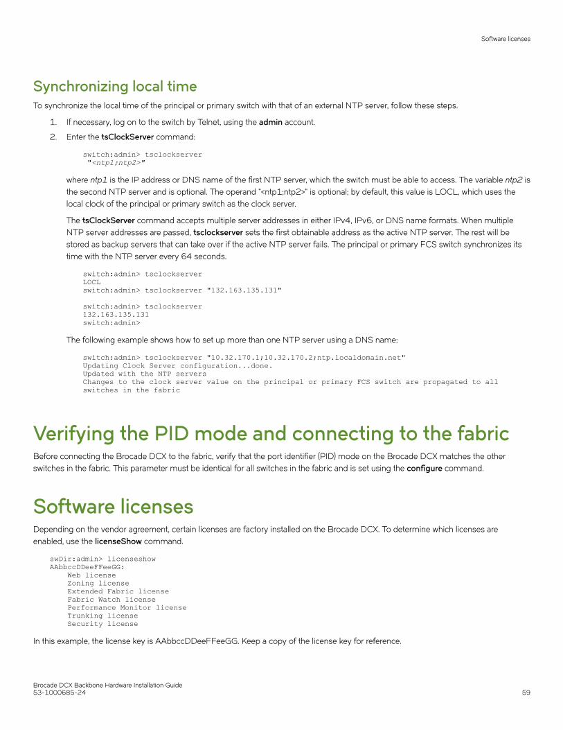
Synchronizing local timeTo synchronize the local time of the principal or primary switch with that of an external NTP server, follow these steps.
1. If necessary, log on to the switch by Telnet, using the admin account.
2. Enter the tsClockServer command:
switch:admin> tsclockserver "<ntp1;ntp2>"
where ntp1 is the IP address or DNS name of the first NTP server, which the switch must be able to access. The variable ntp2 isthe second NTP server and is optional. The operand "<ntp1;ntp2>" is optional; by default, this value is LOCL, which uses thelocal clock of the principal or primary switch as the clock server.
The tsClockServer command accepts multiple server addresses in either IPv4, IPv6, or DNS name formats. When multipleNTP server addresses are passed, tsclockserver sets the first obtainable address as the active NTP server. The rest will bestored as backup servers that can take over if the active NTP server fails. The principal or primary FCS switch synchronizes itstime with the NTP server every 64 seconds.
switch:admin> tsclockserverLOCLswitch:admin> tsclockserver "132.163.135.131" switch:admin> tsclockserver132.163.135.131switch:admin>
The following example shows how to set up more than one NTP server using a DNS name:
switch:admin> tsclockserver "10.32.170.1;10.32.170.2;ntp.localdomain.net"Updating Clock Server configuration...done.Updated with the NTP serversChanges to the clock server value on the principal or primary FCS switch are propagated to all switches in the fabric
Verifying the PID mode and connecting to the fabricBefore connecting the Brocade DCX to the fabric, verify that the port identifier (PID) mode on the Brocade DCX matches the otherswitches in the fabric. This parameter must be identical for all switches in the fabric and is set using the configure command.
Software licensesDepending on the vendor agreement, certain licenses are factory installed on the Brocade DCX. To determine which licenses areenabled, use the licenseShow command.
swDir:admin> licenseshowAAbbccDDeeFFeeGG: Web license Zoning license Extended Fabric license Fabric Watch license Performance Monitor license Trunking license Security license
In this example, the license key is AAbbccDDeeFFeeGG. Keep a copy of the license key for reference.
Software licenses
Brocade DCX Backbone Hardware Installation Guide53-1000685-24 59

The 64-bit chassis ID is required to obtain and activate licenses for the Brocade DCX. The chassis ID is available through thelicenseIdShow command. The licenseShow and licenseIdShow commands must be entered on the active CP blade. Refer to theBrocade Fabric OS Administration Guide for more information.
Installing transceivers and attaching cablesFollow these steps to install SFPs, SFP+s, mSFPs (FC8-64 port card only), or XFPs (FC10-6 port card only) and cables to the BrocadeDCX.
NOTEmSFP transceivers are compatible only with the FC8-64 port blade. While they will fit in other blades, this configuration isunsupported and will generate an error.
The ports are color-coded to indicate which can be used in the same port group for trunking (trunking port groups can be up to eightports). The ports and cables used in trunking groups must meet specific requirements. Refer to the Brocade Fabric OS AdministrationGuide for more information.
1. Position one of the optical transceivers so that the key is oriented correctly to the port. Insert the transceiver into the port until itis firmly seated and the latching mechanism clicks.
Transceivers are keyed so that they can only be inserted with the correct orientation. If a transceiver does not slide in easily,ensure that it is correctly oriented.
2. Position a cable so that the key (the ridge on one side of the cable connector) is aligned with the slot in the transceiver. Insert thecable into the transceiver until the latching mechanism clicks.
Cables are keyed so that they can be inserted in only one way. If a cable does not slide in easily, ensure that it is correctlyoriented.
3. Repeat the above steps for the remaining ports.
4. Organize the cables (see Managing cables on page 60).
5. Verify the Brocade DCX-4S and port status using the switchShow command.
6. Verify fabric connectivity using the fabricShow command.
Managing cablesATTENTIONThe minimum bend radius should be no smaller than 10x the cable radius.
Cables can be organized and managed in a variety of ways: for example, using cable channels on the port sides of the cabinet or patchpanels to minimize cable management. With the horizontal orientation of the blades in the DCX-4S, a pair of vertical cable managementfinger assemblies have been provided to keep the cables from hanging down in front of other blades.
Following is a list of recommendations:
• Leave at least 1 m (3.28 ft) of slack for each port cable. This provides room to remove and replace the Brocade DCX, allows forinadvertent movement of the rack, and helps prevent the cables from being bent to less than the minimum bend radius.
• If ISL Trunking is in use, group the cables by trunking group. The ports are color-coded to indicate which ports can be used inthe same ISL Trunking group: eight ports marked with solid black ovals alternate with eight ports marked with oval outlines.
• Generally, Velcro ® type cable restraints are recommended to avoid creating sharp bends in the cables.
Installing transceivers and attaching cables
Brocade DCX Backbone Hardware Installation Guide60 53-1000685-24

• For easier maintenance, label the fiber optic cables and record the devices to which they are connected.
• Route the cables to the bottom of the DCX through the cable comb.
• Keep LEDs visible by routing port cables and other cables away from the LEDs.
For the procedure to install the ICL cables see Removal and replacement of the inter-chassis link (ICL) cables on page 115
NOTESee "Cabling Best Practices" (available at http://www.brocade.com ) for cable management guidelines.
Verifying correct operation and backing up theconfigurationTo verify correct operation and back up the Brocade DCX configuration, follow these steps.
1. Check the LEDs to verify that all components are functional. For information about LED patterns, see Monitoring SystemComponents on page 63.
2. If necessary, log on to the switch by Telnet, using the admin account.
3. Verify the correct operation of the Brocade DCX by entering the switchShow command from the workstation. This commandprovides information about switch and port status.
4. Verify the correct operation of the Brocade DCX in the fabric by entering the fabricShow command from the workstation. Thiscommand provides general information about the fabric.
5. To back up the configuration, run the following two steps:
a) Enter the configupload -vf command. This command uploads the Brocade DCX virtual fabric data.
b) Enter the configupload command. This command uploads the Brocade DCX configuration.
6. You can run the following commands to see additional configuration information that you can copy to a file to save:
• configShow
• ipaddrShow
• licenseShow
• switchShow
7. Alternatively, you can save the configuration file to a Brocade USB device by using the usbstorage command.
NOTEPasswords are not saved in the configuration file, and are not uploaded during a configurationupload.
Verifying correct operation and backing up the configuration
Brocade DCX Backbone Hardware Installation Guide53-1000685-24 61

Powering off the Brocade DCX1. Shut down the Brocade DCX using the sysShutdown command.
switch::admin> sysshutdownThis command will shutdown the operating systems on your switch.You are required to power-cycle the switch in order to restore operation.Are you sure you want to shutdown the switch [y/n]?yHA is disabledStopping blade 1 Shutting down the blade....Stopping blade 2 Shutting down the blade....Stopping blade 8 Shutting down the blade....Broadcast message from root (pts/1) Tue Aug 23 14:23:06 2008...The system is going down for system halt NOW !!
2. Power off the chassis by flipping the AC power switches on the power supplies to "0" (LEDs inside AC power switches shouldturn off). To maintain the ground connections, leave power cords connected to the power supplies and to the electrical outlets.
Powering off the Brocade DCX
Brocade DCX Backbone Hardware Installation Guide62 53-1000685-24

Monitoring System Components• Monitoring overview......................................................................................................................................................................................... 63• Determining the status of a port, application, or encryption blade............................................................................................... 63• Determining the status of a control processor blade (CP8).............................................................................................................72• Determining the status of a core switch blade (CR8)......................................................................................................................... 74• Determining the status of a power supply...............................................................................................................................................76• Determining the status of a blower assembly........................................................................................................................................77• Determining the status of a WWN card....................................................................................................................................................80
Monitoring overviewThe Brocade DCX is engineered for reliability and requires no routine operational steps or maintenance. This chapter providesinformation about determining the status of each component using LEDs and CLI commands. Refer to the Brocade Web ToolsAdministration Guide and the Brocade Fabric OS Administration Guide for additional information.
Determining the status of a port, application, orencryption blade
1. Check the LEDs on the blade.
• Figure 16 illustrates the FC8-16 port blades.
• Figure 17 illustrates the FC8-32 port blades.
• Figure 18 illustrates the FC8-48 port blade.
• Figure 19 illustrates the FC8-64 port blade.
• Figure 20 illustrates the FS8-18 encryption blade.
• Figure 21 illustrates the FX8-24 extension blade.
• Figure 22 illustrates the FCOE10-24 FCOE blade.
The LED patterns may temporarily change during POST and other diagnostic tests. For information about how to interpret theLED patterns, see the table after the illustrations.
Brocade DCX Backbone Hardware Installation Guide53-1000685-24 63

2. Check the blade status by entering slotShow .
FIGURE 16 FC8-16 Port blade
1. Power LED
2. Status LED
3. Fibre Channel port
4. Port Status LED
Determining the status of a port, application, or encryption blade
Brocade DCX Backbone Hardware Installation Guide64 53-1000685-24

FIGURE 17 FC8-32 Port blade
1. Power LED
2. Status LED
3. Fibre Channel port
4. Port Status LED
Determining the status of a port, application, or encryption blade
Brocade DCX Backbone Hardware Installation Guide53-1000685-24 65

FIGURE 18 FC8-48 Port blade
1. Power LED
2. Status LED
3. Fibre Channel port
4. Port Status LED
Determining the status of a port, application, or encryption blade
Brocade DCX Backbone Hardware Installation Guide66 53-1000685-24
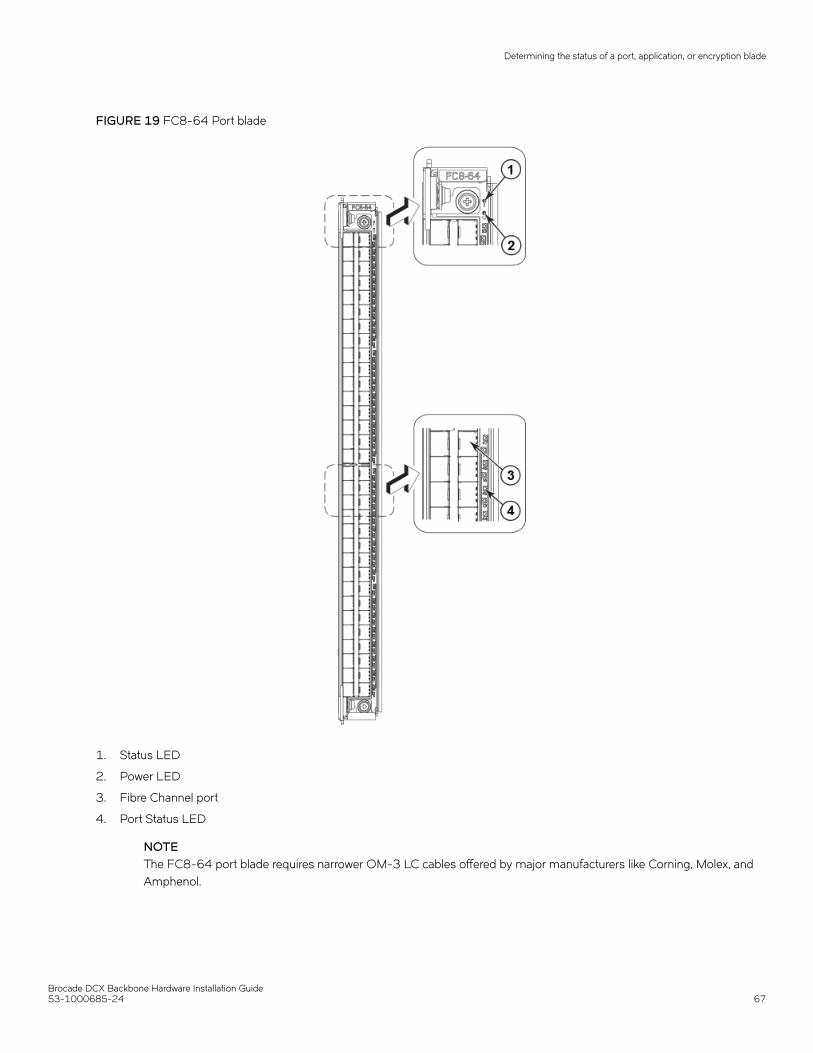
FIGURE 19 FC8-64 Port blade
1. Status LED
2. Power LED
3. Fibre Channel port
4. Port Status LED
NOTEThe FC8-64 port blade requires narrower OM-3 LC cables offered by major manufacturers like Corning, Molex, andAmphenol.
Determining the status of a port, application, or encryption blade
Brocade DCX Backbone Hardware Installation Guide53-1000685-24 67

FIGURE 20 FS8-18 Encryption blade
1. Power LED
2. Status LED
3. Fibre Channel port
4. Port Status LED
Determining the status of a port, application, or encryption blade
Brocade DCX Backbone Hardware Installation Guide68 53-1000685-24

FIGURE 21 FX8-24 Extension blade
1. Power LED
2. Status LED
3. GbE port 6
4. GbE port 6 LED
5. 10GbE port 0
6. 10GbE port 0 LED
7. Port map
Determining the status of a port, application, or encryption blade
Brocade DCX Backbone Hardware Installation Guide53-1000685-24 69

FIGURE 22 FCOE10-24 FCoE blade
1. Power LED10 GbE
2. Status LED
3. 10 GbE FCoE port 9
4. 10 GbE FCoE port 9 LED
5. 10 GbE FCoE port 19
6. 10 GbE FCoE port 19 LED
The following table describes the port and application blade LED patterns and the recommended actions for those patterns.
TABLE 6 Port and application blade LED descriptions
LED purpose Color Status Recommended action
Power LED Steady green Blade is enabled. No action required.
Determining the status of a port, application, or encryption blade
Brocade DCX Backbone Hardware Installation Guide70 53-1000685-24

TABLE 6 Port and application blade LED descriptions (continued)
LED purpose Color Status Recommended action
No light (LED is off) Blade is not powered on. Ensure that the blade is firmlyseated and either thethumbscrew is fully engaged orthe slider is pushed up and theejectors are fully engaged.
Status LED No light (LED is off) Blade is either healthy or doesnot have power.
Verify that the power LED is on.
Steady amber Blade is faulty. Ensure that the blade is firmlyseated and check the status byentering the slotShow command.If LED remains amber, consultthe Brocade DCX supplier.
Slow-flashing amber (on 2seconds, then off 2 seconds)
Blade is not seated correctly or isfaulty.
Pull the blade out and reseat it. IfLED continues to flash, replacethe blade.
Fast-flashing amber (on 1/2second, then off 1/2 second)
Environmental range exceeded. Check for out-of-boundsenvironmental condition andcorrect it.
FC Port Status No light (LED is off) Port has no incoming power, orthere is no light or signal carrierdetected.
Verify that the power LED is on,check the transceiver and cable.
Polling is in progress. Allow 60 seconds for polling tocomplete.
Connected device is configuredin an offline state.
Verify the status of theconnected device.
Steady green Port is online (connected to anexternal device) but has no traffic.
No action required.
Slow-flashing green (on 1second, then off 1 second)
Port is online but segmented,indicating a loopback plug orcable or an incompatible switch.
Verify that the correct device isattached to the Brocade DCX.
Fast-flashing green (on 1/4second, then off 1/4 second)
Port is in internal loopback(diagnostic).
No action required.
Flickering green Port is online, with traffic flowingthrough port.
No action required.
Steady amber Port is receiving light or signalcarrier, but it is not online yet.
Reset the port from theworkstation using the portEnableor portCfgPersistentEnablecommand.
Slow-flashing amber (on 2seconds, then off 2 seconds)
Port is disabled due to diagnostictests or portDisable orportCfgPersistentEnablecommand.
Reset the port from theworkstation using the portEnableor portCfgPersistentEnablecommand.
Fast-flashing amber (on 1/2second, then off 1/2 second)
Transceiver or port is faulty. Change the transceiver or resetthe switch from the workstation.
Alternating green/amber Port is bypassed. Reset the port from theworkstation using the portEnableor portCfgPersistentEnablecommand.
Green, amber, off (cycle is about1 second)
Beaconing initiated on the localswitch.
No action required. Beaconingused to locate/identify port.
Amber, amber, pause (cycle isabout 1 second)
Beaconing initiated on the HBAand reflected on the port.
No action required. Beaconingused to locate/identify port.
Determining the status of a port, application, or encryption blade
Brocade DCX Backbone Hardware Installation Guide53-1000685-24 71

TABLE 6 Port and application blade LED descriptions (continued)
LED purpose Color Status Recommended action
GbE Port Status (FX8-24) - bothGbE and 10GbE ports.
No light (LED is off) Port has no incoming power, orthere is no light or signal carrierdetected.
Verify that the power LED is on,check the transceiver and cable.
Steady green Port is online but has no traffic. No action required.
Slow-flashing green (on 1second, then off 1 second)
Beacon. Used to identify specificports.
No action required.
Flickering green Port is online, with traffic flowingthrough port.
No action required.
Fast-flashing amber (on 1/4second, then off 1/4 second)
Transceiver or port is faulty. Change the transceiver or resetthe switch from the workstation.
10GbE Port Status(FCOE10-24)
No light (LED is off) Port is offline. Verify that the power LED is on,check the transceiver and cable.
Steady green Port is online but has no traffic. No action required.
Flickering green Port is online, with traffic flowingthrough port.
No action required.
Steady amber Port is receiving light but it is notonline yet.
Reset the port by doing ashutdown and no shutdownsequence from a cmsh session.
Slow-flashing amber (on 2seconds, then off 2 seconds)
Port is disabled. Enable the port by using the noshutdown command from acmsh session.
Fast-flashing amber (on 1/4second, then off 1/4 second)
Transceiver or port is faulty. Change the transceiver or resetthe port by doing a shutdownand no shutdown sequence froma cmsh session.
For more information on the CEE Management Shell (cmsh), see the Fabric OS Command Reference Manual or theConverged Enhanced Ethernet Command Reference .
Determining the status of a control processor blade(CP8)
1. Check the LED indicators on the control processor (CP) blade. The LED patterns may temporarily change during POST andother diagnostic tests. For information about how to interpret the LED patterns, see the next table.
Determining the status of a control processor blade (CP8)
Brocade DCX Backbone Hardware Installation Guide72 53-1000685-24

2. Check the port blade status by entering slotShow and haShow .
FIGURE 23 Control processor blade (CP8)
1. Power LED
2. Status LED
3. USB LED
4. USB port
5. Console port (10101)
6. Ethernet port (MGM IP)
7. Ethernet port (SERVICE IP)
8. Active CP LED
Determining the status of a control processor blade (CP8)
Brocade DCX Backbone Hardware Installation Guide53-1000685-24 73

The following table describes the CP blade LED patterns and the recommended actions for those patterns.
TABLE 7 CP blade LED descriptions
LED purpose Color Status Recommended action
Power Steady green CP blade is on. No action required.
No light (LED is off) CP blade is not on. Ensure that the blade is firmlyseated and has power.
Status No light (LED is off) CP blade is either healthy ordoes not have power.
Verify that the power LED is on.
Steady amber CP blade is faulty or the switch isstill booting.
Ensure that the blade is firmlyseated and the switch hascompleted booting. If LEDremains amber, consult theBrocade DCX supplier.
Slow-flashing amber (on 2seconds, then off 2 seconds)
CP blade is not seated correctlyor is faulty.
Pull the blade out and reseat it. Ifthe LED continues to flash,replace the blade.
Fast-flashing amber (on 1/2second, then off 1/2 second)
Environmental range exceeded. Check for out-of-boundsenvironmental condition andcorrect it.
Ethernet Link Status No light (LED is off) Either an Ethernet link is notdetected, or it does not haveincoming power.
Ensure that the blade has power,the Ethernet cable is firmlyseated, and the connected deviceis functioning.
Flickering green/amber Ethernet link is healthy and trafficis flowing through port.
No action required.
Ethernet Link Speed No light (LED is off) Ethernet link speed is 10 Mb/sor CP blade does not haveincoming power.
Ensure that the CP has power.
NOTE: To force a persistentEthernet link speed, enter theifModeSet command.
Steady green Ethernet link speed is100/1000 Mb/s.
No action required.
USB Status Lamp on USB stick enabled. No action required.
Lamp off USB stick not present ordisabled.
No action required.
Active CP Steady blue Active CP blade. No action required.
No light (LED is off) Standby CP blade. No action required.
Determining the status of a core switch blade (CR8)1. Check the LED indicators on the core switch (CR) blade. The LED patterns may temporarily change during POST and other
diagnostic tests. For information about how to interpret the LED patterns, see the next table.
Determining the status of a core switch blade (CR8)
Brocade DCX Backbone Hardware Installation Guide74 53-1000685-24

2. Check the core switch blade status by entering slotShow and haShow .
FIGURE 24 Core switch blade (CR8)
1. Power LED
2. Status LED
3. LINK LED
4. ATTN LED
5. ICL connector
The following table describes the core switch blade LED patterns and the recommended actions for those patterns.
Determining the status of a core switch blade (CR8)
Brocade DCX Backbone Hardware Installation Guide53-1000685-24 75

TABLE 8 CR blade LED descriptions
LED purpose Color Status Recommended action
Power Steady green CP blade is on. No action required.
No light (LED is off) CP blade is not on. Ensure that the blade is firmlyseated and has power.
Status No light (LED is off) CP blade is either healthy ordoes not have power.
Verify that the power LED is on.
Steady amber CP blade is faulty or the switch isstill booting.
Ensure that the blade is firmlyseated and the switch hascompleted booting. Blade maynot be compatible with otherblades in the chassis. See theFCOE10-24 blade section forlimitations. If the LED remainsamber, consult the Brocade DCXsupplier.
Slow-flashing amber (on 2seconds, then off 2 seconds)
CP blade is not seated correctlyor is faulty.
Pull the blade out and reseat it. Ifthe LED continues to flash,replace the blade.
Fast-flashing amber (on 1/2second, then off 1/2 second)
Environmental range exceeded. Check for out-of-boundsenvironmental condition andcorrect it.
LINK LED No light (LED is off) No ICL or ICL cable present, butno connection.
Ensure that the ICL cable iscorrectly installed.
Steady green ICL connected. No action required.
ATTN LED No light (LED is off) ICL operational. No action required.
Blinking amber Attention required. Ensure that the ICL cable iscorrectly installed.
Determining the status of a power supply1. Check the LED indicator on the power supply. The LED patterns may temporarily change during POST and other diagnostic
tests. For information about how to interpret the LED patterns, see the next table.
Determining the status of a power supply
Brocade DCX Backbone Hardware Installation Guide76 53-1000685-24

2. Check the power supply status by entering psShow .
The power supply status displays OK, Absent, or Faulty. If a power supply is absent or faulty, contact the Brocade DCX supplierto order replacement parts.
FIGURE 25 Power supply
1. Power LED
The following table describes the power supply LED patterns and the recommended actions for those patterns.
TABLE 9 Power supply LED descriptions
LED purpose Color Status Recommended action
Power No light (LED is off) Power supply does not haveincoming power and is notproviding power to the BrocadeDCX.
Ensure that the power supply isfirmly seated, the Brocade DCXhas incoming power, both powercables are connected, and ACpower switches are on.
Steady green Power supply has incomingpower and is providing power tothe Brocade DCX.
No action required.
Flashing green Power supply is about to fail. Replace the power supply.
Determining the status of a blower assembly1. Check the LED indicators on the blower assembly. The LED patterns may temporarily change during POST and other
diagnostic tests. For information about how to interpret the LED patterns, see the next table.
Determining the status of a blower assembly
Brocade DCX Backbone Hardware Installation Guide53-1000685-24 77

2. Check the blower assembly status using the fanShow command.
The status for each blower assembly displays OK, Absent, or Faulty. The RPM of each fan in the assembly is also provided. If ablower assembly is absent or faulty, contact the Brocade DCX supplier to order replacement parts.
FIGURE 26 Blower assembly
1. Power LED
2. Fault LED
The following table describes the power supply LED patterns and the recommended actions for those patterns.
TABLE 10 Blower assembly LED descriptions
LED purpose Color Status Recommended action
Power No light (LED is off) Blower assembly does not havepower.
Ensure that the blower assemblyis firmly seated and has power.
Steady green Blower assembly has power. No action required.
Fault No light (LED is off) Blower assembly is either healthyor does not have power.
Ensure that the blower assemblyhas power.
Steady amber Blower assembly has a failure(full or partial).
Replace the blower assembly.
Slow-flashing amber(on 2seconds, then off 2 seconds)
Blower assembly is not seatedcorrectly or is faulty.
Pull the unit out and reseat it. Ifthe LED continues to flash,replace the unit.
Determining the status of a blower assembly
Brocade DCX Backbone Hardware Installation Guide78 53-1000685-24

TABLE 10 Blower assembly LED descriptions (continued)
LED purpose Color Status Recommended action
Flashing amber(on 1/2 seconds,then off 3.5 seconds)
Fan is disabled. Run the fanEnable command toenable the fan.
Fast-flashing amber(on 1/2seconds, then off 1/2 seconds)
Environmental range exceeded. Check for out-of-boundsenvironmental condition, resolveany problems, and reseat theunit. If the LED continues toflash, replace the unit.
Determining the status of a blower assembly
Brocade DCX Backbone Hardware Installation Guide53-1000685-24 79

Determining the status of a WWN cardNOTEThe WWN bezel (logo plate) covers the WWN cards. The LEDs on the WWN cards are not visible unless the bezel is removed.
Enter the chassisShow command to display information about the WWN card. (WWN units correspond to information specificto the WWN card.) Error messages that may indicate problems with a WWN card are summarized in the following table.
TABLE 11 Messages that may indicate WWN card failure
Type of message Sample error message
WWN unit fails its FRU header access. 0x24c (fabos): Switch: switchname, error EM-I2C_TIMEOUT, 2, WWN 1 I2C timed out: state 0x4
WWN unit is being faulted. 0x24c (fabos): Switch: switchname, Critical EM-WWN_UNKNOWN, 1, Unknown WWN #2 is being faulted
WWN unit is not present or is not accessible. 0x24c (fabos): Switch: switchname, Error EM-WWN_ABSENT, 2, WWN #1 not present
Writing to the FRU history log (hilSetFruHistory ) has failed. 0x24c (fabos): Switch: switchname, Error EM-HIL_FAIL, 2, HIL Error: hilSetFruHistory failed, rc=-3 for SLOT 3
FIGURE 27 WWN bezel (logo plate)
1. CP blade Status (above) and Power (below) LEDs
2. CR blade Status (above) and Power (below) LEDs
3. Port blade Status (above) and Power (below) LEDs
4. Slot numbers
The following table describes the WWN card LED patterns and the recommended actions for those patterns.
Determining the status of a WWN card
Brocade DCX Backbone Hardware Installation Guide80 53-1000685-24

TABLE 12 WWN bezel LED descriptions
LED purpose Color Status Recommended action
Port blade/CP blade/CR bladePower
Steady green Power is OK. No action required.
Port blade/CP blade/CRbladeStatus
Steady amber Blade is faulty. Check the blade.
No light (LED is OFF) Blade is OK. No action required.
NOTE: If a blade slot or power supply bay has a filler panel installed, the corresponding LEDs on the WWN blade do not lightup.
Determining the status of a WWN card
Brocade DCX Backbone Hardware Installation Guide53-1000685-24 81

Brocade DCX Backbone Hardware Installation Guide82 53-1000685-24

Removal and Replacement Procedures• Introduction.......................................................................................................................................................................................................... 83• Removal and replacement of the chassis door.....................................................................................................................................83• Removal and replacement of the cable management comb.......................................................................................................... 84• Removal and replacement of the port, application, and encryption blades...............................................................................86• Removal and replacement of the blade filler panel..............................................................................................................................89• Removal and replacement of the control processor blade (CP8)..................................................................................................91• Removal and replacement of the core switch blade (CR8).............................................................................................................. 97• Removal and replacement of the power supply................................................................................................................................ 100• Removal and replacement of the blower assembly......................................................................................................................... 103• WWN card removal and replacement.................................................................................................................................................... 105• Removal and replacement of the transceivers................................................................................................................................... 113• Removal and replacement of the inter-chassis link (ICL) cables................................................................................................ 115• Removal and replacement of the Brocade DCX chassis...............................................................................................................125
IntroductionNOTERead the safety notices before servicing.
The field-replaceable units (FRUs) in the Brocade DCX can be removed and replaced without special tools. The Brocade DCX cancontinue operating during many of the FRU replacements if the conditions specified in the procedures are followed.
The following sections contain FRU removal and replacement procedures (RRPs).
Removal and replacement of the chassis doorNOTEThe chassis door must be installed to ensure the Brocade DCX meets EMI and other regulatory certifications. Additionally, ifICL cables are not used, EMI plugs must be inserted in the ICL cable ports to meet certification standards.
Time and items requiredThe replacement procedure for the chassis door takes less than 5 minutes.
Removing a chassis doorSupport the door to prevent it from falling. Pull and remove the door.
Brocade DCX Backbone Hardware Installation Guide53-1000685-24 83

FIGURE 28 Removal and replacement of the chassis door
Replacing a chassis door1. Align the holes in the door with the pins in the chassis
2. Push the door into place.
Removal and replacement of the cable managementcombThe Brocade DCX can continue to operate during the replacement of the cable management comb.
Removal and replacement of the cable management comb
Brocade DCX Backbone Hardware Installation Guide84 53-1000685-24

Time and items requiredThe replacement procedure for the cable management comb takes less than five minutes. A #1 Phillips screwdriver is required.
Removing a cable management comb1. Remove the chassis door (Removal and replacement of the chassis door on page 83).
2. Remove the cables from the cable management comb and rearrange the cables around the comb.
3. Unscrew and save the four (4) screws holding the comb to the chassis. Support the comb to prevent it from falling.
4. Remove the cable management comb.
FIGURE 29 Removal and replacement of the cable management comb
Removal and replacement of the cable management comb
Brocade DCX Backbone Hardware Installation Guide53-1000685-24 85

Replacing a cable management comb1. Position and tighten the four (4) screws to secure the cable management comb to the chassis.
2. Arrange the cables along the cable management comb.
3. Replace the chassis door (Removal and replacement of the chassis door on page 83).
Removal and replacement of the port, application, andencryption bladesThis section describes how to remove and replace port, application, and encryption blades.
ATTENTIONA blade should be removed only when being replaced with another port, application, or encryption blade, or a filler panel(Removal and replacement of the blade filler panel on page 89). Any slot that is not occupied by a blade should be occupiedby a filler panel to ensure correct cooling of the chassis and protection from dust.
Slots are numbered from 1 through 12, from left to right when facing the port side of the Brocade DCX. Port, application, and encryptionblades can be installed in slots 1 through 4 and 9 through 12.
ATTENTIONThe FCOE10-24 application blade is not compatible with the FC8-64 high-density port blade and the other application blades(FX8-24 and FS8-18) in the same chassis.
Blade DCX DCX-4S DCX 8510-4 DCX 8510-8
FC8-32E port blade No No Supported Supported
FC8-48E port blade No No Supported Supported
FC8-64 port blade Supported Supported Supported Supported
FC16-32 port blade No No Supported Supported
FC16-48 port blade No No Supported Supported
FC16-64 port blade No No Supported Supported
FCOE10-24 application blade Supported Supported No Supported (only in slot 1)
Note: Not supported in the same chassis with FC8-48E, FC8-64, FC16-48, FC16-64, FS8-18, or FX8-24blades.
FS8-18 encryption blade Supported Supported Supported Supported
FX8-24 extension blade Supported Supported Supported Supported
Time and items requiredThe replacement procedure for each blade takes less than 10 minutes. The following items are required for the blade and filler panelreplacement:
• Electrostatic discharge (ESD) grounding strap
• Workstation computer
• Replacement blade or filler panel
• #2 Phillips screwdriver
Removal and replacement of the port, application, and encryption blades
Brocade DCX Backbone Hardware Installation Guide86 53-1000685-24

• Small form-factor pluggable (SFP, SFP+, or mSFP (FC8-64 only)) or extended form-factor pluggable (XFP) (FC10-6 bladeonly) transceivers (as needed)
• Optical cables (as needed)
Removing a bladeATTENTIONFollow ESD precautions.
NOTEThe FC8-16, FC8-32, and FC8-48 blades are compatible with the Brocade DCX, Brocade DCX-4S, and the Brocade 48000.The FC8-64 port blade, the FS8-18 encryption blade, and the FX8-24 and FCOE10-24 blades are compatible only with theBrocade DCX and DCX-4S.
1. Remove the chassis door (Removal and replacement of the chassis door on page 83).
2. Check the power LED, status LED, and port status LED to identify any possible problems. A failed blade can be identified byinspecting the LEDs on the front panel of each blade. See Monitoring System Components on page 63 for LED locations.
3. Establish a Telnet or console session.
Before replacing a blade, establish a Telnet or console connection to determine a failure and verify operation after replacement.Use the slotShow command to view the status of blades.
4. Check for adequate cable slack. Ensure there is plenty of cable slack to remove a blade without cable obstruction.
5. Ensure that the part number on the unit being replaced matches the replacement part number. The chassisShow commanddisplays information about the blades, including part numbers (xx-xxxxxxx-xx), serial numbers, and additional status.
6. Ensure that traffic is not flowing through the blade (port status LED should be off) prior to disconnecting cables.
NOTEBefore removing any cables from a blade, note the cable order (identify each cable by its physical port). It is a goodpractice to keep a table of cable to port mapping. See Cable routing table on page 135 at the end of this chapter for ablank sample table.
NOTEIf multiple blades are being replaced, replace one blade at a time.
7. Disconnect all cables and the SFP, SFP+, or XFP transceivers from the blade. For mSFP transceivers(FC8-64 only), it isrecommended that you use the pull tab to remove the transceiver from the blade before removing the cable from thetransceiver.
8. If removing an FX8-24 extension blade, perform the following steps:
a) Delete all fciptunnel configurations via the portcfg fciptunnel slot / vePort command.
b) Delete all IP Routes defined on the blade to be removed via the portcfg iproute command.
c) Delete all IP interfaces (IPIFs) defined on the blade via the portcfg ipif slot/geX | xgeX command.
d) If logical switches are used on the switch, move all FX8-24 ports back to the default logical switch.
NOTEIf you are removing the FX8-24 blade to install in a different slot, you must remove configuration using the precedingsteps, then reconfigure the blade in the new slot. If you move the blade without performing these steps and the bladefaults, you must move the blade to the original slot and remove configuration.
Removal and replacement of the port, application, and encryption blades
Brocade DCX Backbone Hardware Installation Guide53-1000685-24 87

9. Unscrew the two thumbscrews from the top and bottom ejectors on the blade using the Phillips screwdriver. Unscrew the topthumbscrew until it pops out. This initiates a hot-swap request.
10. Wait for the power LED to turn off in response to the hot-swap request before removing the blade.
11. Open the ejectors by pulling them toward the center of the blade face. Pull the blade out of the chassis using the ejectors.
12. If the blade is not being replaced by another blade, install a filler panel (Removal and replacement of the blade filler panel onpage 89).
FIGURE 30 Removal and replacement of the port, application, and encryption blades (FC8-48 port blade shown)
Replacing a bladeATTENTIONFollow ESD precautions.
1. Orient the blade so that the ports are at the front of the chassis and the flat side of the blade is on the left.
2. Adjust the ejectors to the open position, align the flat side of the blade inside the upper and lower rail guides in the slot, andslide the blade into the slot until it is firmly seated.
3. Adjust the ejectors to the closed position by pulling them away from the center of the blade.
4. Tighten the upper and lower thumbscrews using the Phillips screwdriver.
5. Verify that the power LED on the port blade is displaying a steady green light. If it does not turn on, ensure that the blade isfirmly seated.
Removal and replacement of the port, application, and encryption blades
Brocade DCX Backbone Hardware Installation Guide88 53-1000685-24

6. Install the SFP or SFP+ transceivers and cables in the blade. For mSFP (FC8-64 only) transceivers, it is recommended that youinstall the cables in the transceivers before installing the transceivers in the blade.
7. Group and route the cables through the cable management comb.
8. Replace the chassis door (Removal and replacement of the chassis door on page 83).
Removal and replacement of the blade filler panelThis section describes how to remove and replace blade filler panels.
Removing a filler panelATTENTIONA filler panel should be removed only when being replaced with a port, application, or encryption blade, or another filler panel.Any slot that is not occupied by a blade should be occupied by a filler panel to ensure correct cooling of the chassis andprotection from dust.
1. Remove the chassis door (Removal and replacement of the chassis door on page 83).
2. Unscrew the thumbscrew at the bottom of the panel using the Phillips screwdriver.
Removal and replacement of the blade filler panel
Brocade DCX Backbone Hardware Installation Guide53-1000685-24 89

3. Pull the filler panel out of the chassis.
FIGURE 31 Removal and replacement of the blade filler panel
Replacing a filler panel1. Orient the filler panel.
2. Slide the filler panel into the slot until it is firmly seated.
3. Tighten the thumbscrew at the bottom of the panel.
4. Replace the chassis door (Removal and replacement of the chassis door on page 83).
Removal and replacement of the blade filler panel
Brocade DCX Backbone Hardware Installation Guide90 53-1000685-24

Removal and replacement of the control processorblade (CP8)This section describes how to remove and replace a control processor (CP8) blade. Each Brocade DCX has two CP8 blades located inslot 6 and slot 7.
NOTEIf the new CP blade does not have the same firmware as the active CP blade, the new blade must be upgraded to the samefirmware version. Refer to the Brocade Fabric OS Administration Guide for information.
Time and items requiredThe replacement procedure for the CP blade takes approximately 30 minutes. The following items are required for the CP bladereplacement:
• ESD grounding strap
• Workstation computer
• Serial cable
• IP address of an FTP server for backing up the Brocade DCX configuration
• #2 Phillips screwdriver
• Replacement Brocade DCX CP blade (CP8)
Verifying the necessity of replacementConfirm that you need to replace the CP blade. The following events might indicate that a CP blade is faulty:
• The status LED on the CP blade is lit amber, or the power LED is not lit.
• The CP blade does not respond to Fabric OS commands, or the serial console is not available.
• The slotShow command does not show that the CP blade is enabled.
• The haShow command indicates an error.
• The clock is inaccurate, or the CP blade does not boot up or shut down normally.
• Any of the following messages display in the error log:
– "Slot unknown" message relating to a CP slot– CP blade errors or I2C timeouts– FRU: FRU_FAULTY messages for a CP blade– Configuration loader messages or "Sys PCI config" messages– Generic system driver messages ("FABSYS")– Platform system driver messages ("Platform")– EM messages that indicate a problem with a CP blade– Function fail messages for the CP master
For more information about error messages, refer to the Brocade Fabric OS Message Reference.
Removal and replacement of the control processor blade (CP8)
Brocade DCX Backbone Hardware Installation Guide53-1000685-24 91

Recording critical Brocade DCX informationBack up the Brocade DCX configuration before you replace a CP blade. Refer to the Brocade Fabric OS Administration Guide forbackup information.
1. Connect to the Brocade DCX and log in as admin, using either a Telnet or a serial console connection.
2. Enter haShow to determine which CP blade is active.
switch:admin> haShowLocal CP (Slot 7, CP1) : ActiveRemote CP (Slot 6, CP0) : Standby, HealthyHA Enabled, Heartbeat Up, HA State Synchronized
3. Enter all remaining commands from the serial console for the active CP blade, unless otherwise indicated. For more informationabout commands, refer to the Brocade Fabric OS Command Reference.
4. If one CP blade is faulted, confirm that the other CP blade is now the active CP blade and log in to the active CP blade and skipto Step 7.
5. If both CP blades are healthy and you want to replace the standby CP blade, log in to the active CP blade and skip to Step 7.
6. If both CP blades are healthy and you want to replace the active CP blade, log in to the active CP blade and run the followingsteps:
a) Run the hafailover command to make the standby CP blade the active blade. The currently active CP blade becomes thestandby blade. Wait until the status LED on the currently active CP blade is no longer lit.
b) Confirm the completion of the failover by running the hashow command.
c) Log in to the new active CP blade.
d) Run the firmwareshow command to confirm the firmware version of the active CP blade.
e) Run the hadisable command to prevent failover or communication between the CP blades during the replacement.
f) Continue with Step 7.
7. Enter firmwareShow to note the firmware version of the active CP blade.
8. Enter haDisable from the active CP blade to prevent failover or communication between the CP blades during the replacement.
9. Logged in to the active CP, run the following two steps to upload the Brocade DCX configuration to a specified FTP server.Enter information at the prompts.
a) Enter the configupload -vf command. This command uploads the virtual fabric data.
b) Enter the configupload -all command. This command uploads the chassis and switch configuration for all logicalswitches. .
c) Enter configupload --map to upload port-to-area mapping information.
With Fabric OS 7.4.0, you need to upload the configuration with -map option in a FICON-enabled DCX 8510 chassis ifport-bound addressing is used.
Power-up procedureUse the procedures in this section to remove and replace a single control processor (CP) blade while chassis power is on. To replace bothCP blades, refer to the power-down replacement procedures.
Removing a control processor blade (CP8)The Brocade DCX continues to operate while a CP blade is being replaced if the redundant CP blade is active and a failover does notoccur. You can prevent failover by entering the haDisable command.
Removal and replacement of the control processor blade (CP8)
Brocade DCX Backbone Hardware Installation Guide92 53-1000685-24
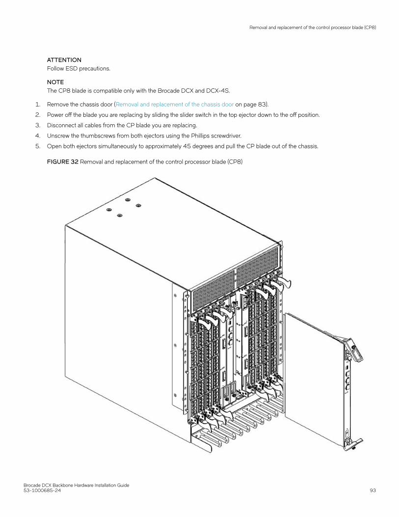
ATTENTIONFollow ESD precautions.
NOTEThe CP8 blade is compatible only with the Brocade DCX and DCX-4S.
1. Remove the chassis door (Removal and replacement of the chassis door on page 83).
2. Power off the blade you are replacing by sliding the slider switch in the top ejector down to the off position.
3. Disconnect all cables from the CP blade you are replacing.
4. Unscrew the thumbscrews from both ejectors using the Phillips screwdriver.
5. Open both ejectors simultaneously to approximately 45 degrees and pull the CP blade out of the chassis.
FIGURE 32 Removal and replacement of the control processor blade (CP8)
Removal and replacement of the control processor blade (CP8)
Brocade DCX Backbone Hardware Installation Guide53-1000685-24 93

Replacing a control processor blade (CP8)
ATTENTIONFollow ESD precautions.
1. Open the ejector handles to approximately 45 degrees. Orient the CP blade so that the handles are toward you and the flatmetal side is on your left.
2. Align the flat metal side of the CP blade inside the lower and upper blade guides in the slot. Slide the CP blade into the slot untilit is firmly seated.
3. Tighten the thumbscrews inside each handle using the Phillips screwdriver.
4. Turn the CP blade on by sliding the ON/OFF switch in the top handle up, to cover the thumbscrew.
5. Verify that the power LED is green. If not, ensure that the CP blade has power and is firmly seated and that the ejectors are inthe locked position.
6. Connect the cables to the new CP blade.
7. Remain logged in to the active CP and continue to Verifying operation of the new CP blade on page 95
Power-down procedureUse the following procedure to power down the chassis and replace both CP blades. You can replace a single CP blade using the power-up procedures.
1. Remove the chassis door.
2. If you haven't already done so, enter configupload - all, specifying a file name for saving configuration data.This saves all system configuration data including chassis and switch configuration for all logical switches to the file namespecified. For more information, refer to the Brocade Fabric OS Command Reference.
3. If you haven't already done so, enter configupload -vf, specifying a file name for saving configuration data.This saves the backbone virtual fabric data to the file name specified. For more information, refer to the Brocade Fabric OSCommand Reference.
4. If you haven't already done so, enter configupload -map, specifying a folder name.This command saves the port-to-area addressing mode configuration files to the folder specified. With Fabric OS 7.4.0, youneed to upload the configuration with -map option in a FICON-enabled DCX 8510 chassis if port-bound addressing is used.For more information, refer to the Brocade Fabric OS Command Reference.
5. Power down the chassis.
6. Remove CP blades using the following steps:
a) Disconnect all cables from the blades.
b) Unscrew the thumbscrew from both ejectors for a blade using the Phillips screwdriver.
c) Lever open both ejector handles simultaneously to approximately 45 degrees and pull the CP blade out of the chassis.
7. Replace the blades using the following steps:
a) Open the ejector handles to approximately 45 degrees. Orient the CP blade so that the handles are toward you.
b) Align the flat metal side of the CP blade inside the blade guides in the slot. Slide the CP blade into the slot until it is firmlyseated.
c) Tighten the thumbscrew inside each handle using the Phillips screwdriver.
d) Turn the CP blade on by sliding the ON/OFF switch in the left handle to the left to cover the thumbscrew.
8. Power up the chassis.
Removal and replacement of the control processor blade (CP8)
Brocade DCX Backbone Hardware Installation Guide94 53-1000685-24

9. Verify that each blade's power LED is green. If not, ensure that the CP blade has power and is firmly seated and that the ejectorsare in the locked position.
10. Connect the cables to the new CP blade.
11. Enter chassisDisable.
12. Enter configDownload -vf to download backbone virtual fabric data to the local system.The chassis reboots and partitions are restored.
13. Enter chassisDisable.
14. Enter configDownload -map to download port-to-area addressing mode configuration files to the local system.
15. Enter chassisReboot -m.The system recovers.
16. Enter chassisDisable.
17. Enter configDownload -all to download system configuration data, including chassis and switch configuration for all logicalswitches, to the local system.All the licenses, configurations, and FCIP tunnels are restored.
18. Enter reboot.The chassis becomes fully functional with the new CP blades.
Verifying operation of the new CP bladeTo verify that boot and POST are complete on the new CP blade and that the CP blade has achieved failover redundancy, perform thefollowing steps.
1. Type slotShow. The command output shows the new CP blade as "enabled."
2. Log into each CP blade and enter the haShow command to display the CP status. Verify the CP state, status, health, and thatthe HA state is synchronized. Remedy any issues before proceeding. For more information on haShow output, refer to theBrocade Fabric OS Command Reference.
3. Determine the version by typing firmwareShow .
4. If the firmware versions for both CP blades are the same, skip to Downloading firmware from an FTP server on page 96
If the firmware version on the replacement blade does not match that on the active CP blade, the following warning messageappears with the results of the firmwareshow command:
WARNING: The local CP and remote CP have different versionsof firmware, please retry firmwaredownload command.
5. Bring the replacement blade firmware to the same firmware level as the active blade using one of the following procedures:
• Run the firmwaresync command on the active CP blade to copy all firmware from the active CP blade to the standby CPblade.
NOTEUsing this command requires that existing telnet, secure telnet or SSH sessions to the standby CP blade to berestarted.
• Run the firmwareDownload -s command on the replacement blade to bring it up to the proper level.
Removal and replacement of the control processor blade (CP8)
Brocade DCX Backbone Hardware Installation Guide53-1000685-24 95

6. Perform one of the following tasks to download firmware:
• If you are using an FTP server to download the firmware, skip to Downloading firmware from an FTP server on page 96.
• If you are using a USB device to download the firmware, skip to Downloading firmware from a USB device on page 96. Ifthe firmware on the standby CP blade is more than one level down from the level on the active CP blade, you must haveformatted USB devices for each of the versions you will need to upgrade.
For details on supported upgrade paths and steps to upgrade through multiple versions of Fabric OS, refer to the Fabric OSRelease Notes, and the Fabric OS Upgrade Guide.
Downloading firmware from an FTP server1. Log out of the active CP blade and log in to the standby CP blade.
2. Type firmwareDownload -s to download the firmware to the standby CP blade. The -s option also disables the autoreboot, soyou will have to manually issue a reboot after the download finishes to initiate firmwarecommit. Enter all requested information(use default values).
3. Type firmwareDownloadStatus to verify that the firmware has been updated.
4. Ensure that you are still logged in to the standby CP blade (the blade for which you just changed the firmware level) and typereboot . The reboot of the standby CP will initiate a firmwarecommit to the secondary partition and log you out.
5. Log back in to the standby CP blade and type firmwaredDownloadStatus on the standby CP blade to validate a successfulcommit. This may take 10 minutes.
6. Log out of the standby CP blade and log in to the active CP blade.
7. Type haEnable to re-enable HA on the active CP blade.
NOTEFor Fabric OS 6.3.0 and later, haEnable will cause the standby CP blade to reboot. Wait until the power cycles and thePOST completes before moving to the next step.
8. Type haShow and verify that the command output includes "HA Enabled Heartbeat Up". If not, re-enter the command until youhave verified that redundancy is achieved.
9. Type version or firmwareShow to verify that the firmware version has been updated.
10. Pack the faulty CP blade in the packaging provided with the new CP blade, and contact the Brocade DCX supplier to determinethe return procedure.
11. Replace the chassis door (Removal and replacement of the chassis door on page 83).
Downloading firmware from a USB deviceThe folder structure on the USB device must be as follows in order to allow the device to be enabled:
• brocade>
– config– firmware– firmwareKey– support
The firmware folder contains the folder for the specific release you are installing.
1. Insert the USB device into the active CP blade.
2. Attach a serial cable from the PC to the active CP blade.
3. Log in to the active CP blade and type usbStorage - e to enable the USB device.
Removal and replacement of the control processor blade (CP8)
Brocade DCX Backbone Hardware Installation Guide96 53-1000685-24

4. Remove the serial cable from the active CP blade and attach it to the standby CP blade.
5. Type firmwareDownload -s -U vX.X.X (where X.X.X is the firmware version you are downloading) to download the firmware tothe standby CP blade.
The -s option also disables the autoreboot, so you must manually issue a reboot after the download finishes to initiatefirmwarecommit. Enter all requested information (use default values).
The -U option indicates that the download should come from the USB device. If you do not use this option, you are promptedwith Download from USB [No}: Type Y to download from the USB device.
6. When the download process finishes, type firmwareDownloadStatus to verify that the firmware has been updated.
7. Ensure that you are still logged in to the standby CP blade (the blade for which you just changed the firmware level) and typereboot. The reboot of the standby CP will initiate a firmwarecommit to the secondary partition and log you out.
8. Log back in to the standby CP blade and type firmwareDownloadStatus on the standby CP blade to validate a successfulcommit. This may take 10 minutes.
9. Log out of the standby CP blade and log in to the active CP blade.
10. Type haEnable to re-enable HA on the active CP blade.
11. Type haShow and verify that the command output includes "HA enabled, Heartbeat Up, HA State synchronized". If not, re-enterthe command until you have verified that redundancy is achieved.
12. Type firmwareShow to verify that the firmware version has been updated and that the versions are the same on the two CPblades.
13. Pack the faulty CP blade in the packaging provided with the new CP blade, and contact the switch supplier to determine thereturn procedure.
14. Replace the chassis door (Removal and replacement of the chassis door on page 83).
Removal and replacement of the core switch blade(CR8)This section describes how to remove and replace a core switch blade (CR8). The Brocade DCX has two core switch blades: one in slot 5and one in slot 8. Note that the blade shown in the removal illustration (Removing a core switch blade (CR8) on page 98) is shown withEMI plugs installed.
Time and items requiredThe replacement procedure for the core switch blade takes approximately 30 minutes. The following items are required for the coreswitch blade replacement:
• ESD grounding strap
• #2 Phillips screwdriver
• Replacement Brocade DCX CR8 core switch blade
Verifying the necessity of replacementConfirm that you need to replace the core switch blade. The following events might indicate that a core switch blade is faulty:
• The status LED on the core switch blade is lit amber, or the power LED is not lit.
• The slotShow command does not show that the core switch blade is enabled.
Removal and replacement of the core switch blade (CR8)
Brocade DCX Backbone Hardware Installation Guide53-1000685-24 97

• The haShow command indicates an error.
• Any of the following messages display in the error log:
– "Slot unknown" message relating to a core switch blade slot– Core switch blade errors or I2C timeouts– FRU: FRU_FAULTY messages for a core switch blade– Configuration loader messages or "Sys PCI config" messages– Generic system driver messages ("FABSYS")– Platform system driver messages ("Platform")– Error messages that indicate a problem with a core switch blade– Function fail messages for the core switch blade master
For more information about error messages, refer to the Brocade Fabric OS Message Reference.
Removing a core switch blade (CR8)The Brocade DCX continues to operate while a core switch blade is being replaced.
ATTENTIONFollow ESD precautions.
NOTEThe CR8 blade is compatible only with the Brocade DCX.
1. Remove the chassis door (Removal and replacement of the chassis door on page 83).
2. Power off the blade by sliding the slider switch in the top ejector down to the off position. Do not eject the blade until the powerLED has gone off and you have completed the next two steps.
3. Disconnect cables from the faulty core switch blade.
4. Unscrew the thumbscrews from both ejectors using the Phillips screwdriver.
Removal and replacement of the core switch blade (CR8)
Brocade DCX Backbone Hardware Installation Guide98 53-1000685-24

5. Open both ejectors simultaneously to approximately 45 degrees and pull the core switch blade out of the chassis.
FIGURE 33 Removal and replacement of the core switch blade (CR8)
Replacing a core switch blade (CR8)ATTENTIONFollow ESD precautions.
1. Open the ejector handles to approximately 45 degrees.Orient the CP blade so that the handles are toward you and the flatmetal side is on your left.
2. Align the flat metal side of the core switch blade inside the upper and lower blade guides in the slot. Slide the core switch bladeinto the slot until it is firmly seated.
Removal and replacement of the core switch blade (CR8)
Brocade DCX Backbone Hardware Installation Guide53-1000685-24 99

3. Close the ejector handles and then tighten the thumbscrews inside each handle using the Phillips screwdriver.
4. Turn the core switch blade on by sliding the ON/OFF switch in the top handle up, to cover the thumbscrew.
5. Verify that the power LED is green (might require a few seconds). If not, ensure that the core switch blade has power and isfirmly seated and that the ejectors are in the locked position.
6. Connect the cables to the new core switch blade. If ICL cables are not used, insert EMI plugs into the cable sockets.
7. Replace the chassis door (Removal and replacement of the chassis door on page 83).
8. Pack the faulty core switch blade in the packaging provided with the new core switch blade, and contact the Brocade DCXsupplier to determine the return procedure.
Removal and replacement of the power supplyUse this procedure to remove and replace a power supply.
NOTEThe Brocade DCX can continue operating during the replacement if at least one 220 VAC power supply is operating or at leasttwo 110 VAC power supplies are working. DCX power supplies are 100-240 VAC, auto-sensing.
NOTEA chassis with slots for eight port blades can have up to four power supplies installed. If you are adding additional powersupplies, you can use the procedures in this section under "Replacing a power supply" to install the new power supplies. Be sureto follow steps on those procedures to enable sending notifications when the additional power supplies fail.
Time and items requiredThe replacement procedure for each power supply takes less than 5 minutes. A power supply unit or filler panel is required for the powersupply replacement.
Identifying power suppliesThe following figure shows the location and identification of the power supplies.
FIGURE 34 Power supply identification
1. Power supply 1 (PS1)
2. Power supply 2 (PS2)
Removal and replacement of the power supply
Brocade DCX Backbone Hardware Installation Guide100 53-1000685-24

3. Power supply 3 (PS3)
4. Power supply 4 (PS4)
Power-cord noticeDANGERThis device might have more than one power cord. To reduce the risk of electric shock, disconnect all power cords beforeservicing.
Removing a power supply1. Perform the appropriate following action based on whether the Brocade DCX is operating:
• If the Brocade DCX is not operating during the replacement procedure, go to step 2.
• If the Brocade DCX is operating and will continue to operate during the replacement, check the power LEDs to verify thatthe minimum number of power supplies is functioning. A fully populated Brocade DCX requires a minimum of one powersupply at all times.
2. Turn off the power switch.
3. Remove the power cord.
4. Loosen the thumbscrew.
5. Grasp the handle and pull, sliding the power supply from the chassis and supporting the power supply from beneath as youremove it.
Removal and replacement of the power supply
Brocade DCX Backbone Hardware Installation Guide53-1000685-24 101

6. If you are not replacing the power supply, insert a filler panel into the slot.
FIGURE 35 Removal and replacement of the power supply
Replacing a power supply1. Remove any filler panel.
2. Insert the power supply into the slot. Verify that the power supply is seated by gently pulling on the handle. The power supplyshould resist movement as you pull.
3. Tighten the thumbscrew.
4. Replace the power cord.
5. Turn on the power switch.
Removal and replacement of the power supply
Brocade DCX Backbone Hardware Installation Guide102 53-1000685-24

6. Verify that the power LED on the power supply displays a steady green light.
7. If you are installing two additional power supplies to bring the total power supplies up to four, perform one or both of thefollowing tasks to enable sending notifications if one power supply fails.
NOTEA maxiumum of four power supplies can be installed in the chassis.
• For Fabric Watch monitoring, change the switchStatus policy settings to the following:
switch.status.policy.PowerSupplies.down = 1switch.status.policy.PowerSupplies.marginal = 0
For more details on executing the switchStatusPolicyShow and switchStatusPolicySet commands, refer to the Fabric OSCommand Reference.
• For Monitoring and Alerting Policy Suite (MAPS) monitoring, follow procedures to update the active MAPS power supplyswitchstatus policy settings for four PSU devices in the "Additional MAPS features" section of the Brocade Monitoring andAlerting Policy Suite Administrator's Guide.
Removal and replacement of the blower assemblyThis procedure provides instructions for removing and replacing a blower assembly.
ATTENTIONThe Brocade DCX can continue operating during the replacement if the other two blower assemblies are operating,To ensurecontinuous adequate cooling, maintain three operating blower assemblies at all times except for the brief period when replacinga blower assembly.
Time and items requiredThe replacement procedure for each blower assembly takes less than 5 minutes. The following items are required for the blowerassembly replacement:
• Replacement blower assembly
• #2 Phillips screwdriver
Removing a blower assembly1. Before removing a blower assembly, verify that the other blower assemblies are functioning correctly. The power LEDs should
be steady green.
2. Use the screwdriver to loosen the captive screws at the top and bottom of the blower assembly.
Removal and replacement of the blower assembly
Brocade DCX Backbone Hardware Installation Guide53-1000685-24 103

3. Grasp the handle and pull, sliding the blower assembly from the chassis and supporting the blower assembly from beneath asyou remove it.
FIGURE 36 Removal and replacement of the blower assembly
Replacing a blower assembly1. Orient the blower assembly and slide it into the chassis, pushing firmly to ensure that it is seated.
2. Verify that the power LED displays a green light.
3. Use the screwdriver or your fingers to tighten the captive screws.
Removal and replacement of the blower assembly
Brocade DCX Backbone Hardware Installation Guide104 53-1000685-24

WWN card removal and replacementThere are two WWN cards located beneath the WWN bezel (logo plate). As you are facing the bezel on the non-port-side of the chassis,WWN 1 is located on the left side, and WWN 2 is on the right. Before replacing cards, refererence RASlog messages and use the WWNRecovery Tool (wwnrecover) as directed in the following sections to recover WWN cards. The tool will direct you to contact customersupport if recovery fails. In these cases, Brocade Support will determine whether one or both WWN cards need replaced and will requestthe partner or OEM to send WWN cards from FRU inventory to the nearest Brocade Support office to be reprogrammed.
This section provides information on RASlog messages indicating WWN card problems, the WWN Recovery Tool, and complete steps toremove and replace WWN cards.
The following WWN card replacement procedures are available:
• Hot-swap procedure. Use this procedure when replacing one WWN card only. This procedure is non-disruptive as a systemreboot is not required under most conditions.
NOTEAfter replacing a WWN card using this procedure, RASlog messages EM-1220 or EM-1222 may indicate that adiscrepancy or mismatch is detected between the WWN cards. You must monitor messages for errors and warnings,and then follow directions in messages to use wwnrecover for recovery . The wwnrecover tool may prompt you toreboot the control processors (CP) if the system is running with invalid IP addresses because the system was bootedwith a replacement card for WWN card 1.
• System power-down procedure. Use this procedure when replacing both WWN cards. This procedure disrupts systemoperations. Observe the following when replacing both WWN cards:
– No additional reboot is required following card replacement after powering the system down.– If Brocade support has determined that both WWN cards need replaced, you must power-down the chassis, and then
replace both WWN cards as a matched pair.– Be aware that if replacing both WWN cards, the IP addresses on the new WWN cards will be in effect when the chassis
powers up. If these IP addresses are different from the previous cards, then you will not be able to establish ssh or othersessions that use the previous IP addresses. You can change IP addresses on the new cards using the ipaddrsetcommand.
NOTEIf replacing the chassis, you do not need to remove WWN cards from chassis as they ship with replacement chassis.
Time and items requiredIf there is a need to replace one or both WWN cards, allow approximately 20 minutes. Refer to Using wwnrecover 7.4 on page 106 and Verifying the need for replacement on page 106 before replacement.
The following items are needed to replace the WWN cards:
• Electrostatic discharge (ESD) grounding strap
• #2 Phillips screwdriver (required only for some versions of the WWN card)
• If a serial console session is used: serial cable and a workstation computer with a terminal emulator application (such asHyperTerminal for Windows systems or TIP for Solaris systems)
WWN card removal and replacement
Brocade DCX Backbone Hardware Installation Guide53-1000685-24 105

Using the wwnrecover utilityThe wwnrecover utility permits a recovery of WWN card data in the event of corruption. Recovery is not possible if hardware issuesprevent access to either WWN card or if the primary and backup copy of the license ID on either card is corrupted. This utility is notavailable in Fabric OS prior to v7.4.0.
Identical data must be maintained on each WWN card at all times so that if one card fails, the system can use the other card to providevalid system operation. To maintain data and ensure its integrity, the audits both WWN cards one hour after the first system boot-up,every 24 hours after boot-up, and any time a WWN card is inserted to compare the critical data.
If a data mismatch is detected during the audit, messages in the RASlog will provide a summary of all errors detected and prompt youthrough a data recovery process. The data recovery mechanism may vary depending on the error encountered and the data beingcompared. Problems such as a mismatch between license IDs cannot be fixed with wwnrecover, and the output will direct you to callBrocade Technical Support. For other problems, running wwnrecover can pinpoint the problem and, in some cases, permit you to fix it.Mismatched data can be resolved, and corrupt data can sometimes be recovered.
The following table lists RASlog messages that can occur during the WWN card audit routine.
TABLE 13 RASlog messages from WWN card audit
Error message Issue
[EM-1220]...M1, ERROR ... A problem was found on one or both CIDcards (x), please run the wwnrecover tool to get more information andrecovery options.
Some kind of error or mismatch has been detected in the WWN cardaudit.
[EM-1221], ... M1, INFO, ... A WWN card has been inserted, a WWNverification audit will be run to detect any mismatches or other problems.
A second WWN card is enabled and the WWN card audit will be run. If anerror is detected during the audit, EM-1220 and EM-1222 messages aregenerated.
[HIL-1650], CHASSIS, ERROR...Unable to detect WWN card in chassis.Access to WWN halted...
WWN card has been removed from the chassis. Replace as soon aspossible since system is in degraded state.
[EM-1222], ... M1, WARNING, ... A WWN card access problem has beenencountered, please run the wwnrecover tool to get more information andrecovery options.
An error is detected during normal access to the WWN cards; typically,one of the cards is corrupted or inaccessible.
Recovery is not possible. Please contact Brocade Technical Support forreplacement of the corrupted or inaccessible WWN(s).
The license ID on the two WWN cards do not match.
The wwnrecover utility must be used to maintain data integrity when replacing one or both WWN cards using instructions in the WWNcard removal and replacement section. To run wwnrecover, log in as admin and enter the following command:
switch:admin# wwnrecover
For more information on wwnrecover and command syntax, refer to the Brocade Fabric OS Command Reference.
Verifying the need for replacementBefore replacing a WWN card, verify that the replacement is necessary. Any of the following events can indicate that the card requiresreplacement:
• Status LEDs on the WWN bezel not reflecting the actual status of the components.
• Power or Status LEDs on WWN card (beneath logo plate) indicate a problem.
• Problems viewing or modifying the data stored on the WWN card.
• Error messages regarding WWN units #1 or #2 from the chassisshow output.
• If an EM-1220 or EM-1222 error message occurs in the RASlog and WWN card recovery is not successful usingwwnrecover.
WWN card removal and replacement
Brocade DCX Backbone Hardware Installation Guide106 53-1000685-24

NOTEIn the event of an EM-1220 or EM-1222 error message due to WWN card data corruption or data mis-matches across WWNcords, data recovery may be possible using the wwnrecover utility. For more information on using this utility, refer to Usingwwnrecover on page 106.
Preparing for WWN card replacementIf the WWN cards require replacement, complete the following steps. Follow electrostatic discharge (ESD) precautions.
DANGERFor safety reasons, the ESD wrist strap should contain a series 1 megaohm resistor.
1. Open a Telnet session to the chassis and log in to the active CP as admin. The default password is "password".
2. Verify that you are logged in to the active CP. Run the haShow command to determine the active CP.
3. Run the supportSave command on the active CP to capture all settings. These settings will be referenced to verify the settingshave been correctly programmed after WWN replacement.
4. Contact Brocade Technical Support for replacement of WWN cards. Brocade Support will request the partner or OEM to sendWWN cards from FRU inventory to the nearest Brocade Support office to be reprogrammed. Brocade Support will require theSupportsave data taken in the previous step so that the replacement cards can be reprogrammed prior to shipping to thepartner or your site. If Brocade support has determined that both WWN cards need replaced, you must power-down thechassis, and then replace both WWN cards as a matched pair.
NOTEDo not execute the frureplace command. The command will no longer be functional beginning with the release ofFabric OS 7.0.0c, but users with earlier versions of the Fabric OS should also not run the command.
Hot-swap replacementYou may replace one WWN card with the system powered on using the following steps to avoid interruption of system operation.
Use this procedure if Brocade Customer Support has determined that a WWN card needs replaced and you have received replacementcards. These procedures require use of the wwnrecover utility. For more information on this utility, refer to Using wwnrecover on page106.
You can use this procedure to replace one WWN card at a time while power is on. Follow all steps for one card, and then repeat the samesteps to replace the other card. To replace both WWN cards simultaneously, use procedures under Power-down replacement on page108.
1. Remove the defective WWN card using procedures under Removing the WWN card and WWN bezel (logo plate) on page 110applicable to hot-swap replacement of WWN cards.
NOTE
Do not use steps in the WWN card and WWN bezel removal procedures to disable logical switches and power down thechassis.
Removing a WWN card will result in RASlog messages indicating that a WWN card cannot be detected. Since the system will bein a degraded state, install a WWN card as soon as possible.
2. Install the replacement WWN card into the empty slot.
When replacing cards, hold each card by the edges and insert the WWN cable onto the WWN module until the cables are fullyseated.
WWN card removal and replacement
Brocade DCX Backbone Hardware Installation Guide53-1000685-24 107

3. Verify that the WWN card is correctly connected by noting if the LEDs on the card reflects the status of the components.
4. Address any issues flagged by any RASlog EM-1220 and EM-1222 messages that display for the new card beforeproceeding.
NOTEIssues relating to data recovery on new WWN cards must be resolved at this point before proceeding to avoid invalidWWN data, errors, and operating problems. If EM-1220 messages indicate that IP addresses on installed WWN cardsdo not match, follow instructions in the message to recover the IP address so that both cards use the same address.
5. Determine the active CP by entering the haShow command.
6. On the active CP, run the wwnrecover command and specify the WWN card that you replaced (WWN 2 or WWN 1) whenprompted.
7. If wwnrecover messages prompt for a system reboot, reboot both CPs to ensure the system is running with valid WWN carddata.
8. Enter the hafailover command to force failover so that the standby CP becomes the active CP.
This command is necessary so that the correct IP address for the new card displays for the ipaddrshow command. For moreinformation on these commands, refer to the Brocade Fabric OS Command Reference.
9. Verify the new card settings by running the following commands and comparing the output with the original supportsave data:
• licenseidshow
• ipaddrshow
• switchname
• chassisname
• wwncardshow ipdata
• chassisshow (look at the WWN and Chassis information at the bottom)
10. If replacing the second WWN card, repeat steps 1-11 for the other card.
11. Install the WWN bezel. Orient the bezel on the chassis. Insert and tighten the screws.
12. Pack faulty WWN cards in the packaging provided with the replacement cards, and return them to Brocade Support for failureanalysis (FA).
Power-down replacementUse these procedures when you can interrupt system operation and replace one or both WWN cards with the system powered down.
Use this procedure if Brocade Customer Support has determined that a WWN card needs replaced and you have received thereplacement card. These procedures require use of the wwnrecover utility.
NOTEYou can use this procedure if replacing one or both WWN cards, however you must use this procedure if replacing both WWNcards. If Brocade support has determined that both WWN cards need replaced, you must power-down the chassis, and thenreplace both WWN cards as a matched pair. Obtain replacement cards through your Brocade product support representative.
Follow electrostatic discharge (ESD) precautions. Wear a wrist grounding strap connected to chassis ground (if the chassis is plugged in)or a bench ground.
DANGERFor safety reasons, the ESD wrist strap should contain a series 1 megaohm resistor.
WWN card removal and replacement
Brocade DCX Backbone Hardware Installation Guide108 53-1000685-24

NOTEBe aware that if replacing both WWN cards, the IP addresses on the new WWN cards will be in effect when the chassis powersup. If these IP addresses are different from the previous cards, then you will not be able to establish ssh or other sessions thatuse the previous IP addresses. You can change IP addresses on the new cards using the ipaddrset command.
1. Unpack the replacement WWN card(s) and save the packaging for the faulty WWN card(s).The WWN cards and cables are labeled #1 for the left slot and #2 for the right slot.
2. Power down the chassis and remove the defective WWN card(s) following appropriate steps under Removing the WWN cardand WWN bezel (logo plate) on page 110.
NOTEThere are two WWN cards located beneath the WWN bezel (logo plate). As you are facing the bezel, WWN 1 is locatedon the left side, and WWN 2 is on the right.
3. Install the replacement WWN card into the empty slot.
When replacing cards, hold each card by the edges and insert the WWN cable onto the WWN module until the cables are fullyseated.
4. Power on the chassis and wait for five minutes for the chassis to boot.
5. Verify that the new WWN card is correctly connected by noting if the LEDs on the card reflects the status of the components.
NOTEThe LEDs may take up to two minutes after WWN card installation to begin functioning.
6. Resolve any issues flagged by RASlog EM-1220 and EM-1222 messages that display for the new card(s) before proceeding.
NOTEIssues relating to data recovery on new WWN cards must be resolved at this point before proceeding to avoid invalidWWN data, errors, and operating problems.
7. Determine the active CP by entering the haShow command.
8. On the active CP, run the wwnrecover command and specify WWN 2 card for recovery when prompted in wwnrecover outputmessages. Refer to Using wwnrecover on page 106 for more information on this command.
9. If wwnrecovermessages prompt for a system reboot, reboot both CPs to ensure the system is running with valid WWN carddata.
10. Verify the new card settings by running the following commands and comparing the output with the original supportsave data:
• licenseidshow
• ipaddrshow
• switchname
• chassisname
• wwncardshow ipdata
• chassisshow (look at the WWN and Chassis information at the bottom)
11. Run the switchcfgpersistentenable command to persistently enable each logical switch, that was disabled before removing theWWN card(s):
switch:FID128:root> switchcfgpersistentenableSwitch's persistent state set to 'enabled'
12. Install the WWN bezel on the chassis.
a) Orient the bezel on the chassis.
b) Insert and tighten the screws.
WWN card removal and replacement
Brocade DCX Backbone Hardware Installation Guide53-1000685-24 109

13. Pack faulty WWN cards in the packaging provided with the replacement cards, and return them to Brocade Support for failureanalysis (FA).
Removing the WWN card and WWN bezel (logo plate)Two WWN cards located beneath the WWN bezel (logo plate). As you are facing the bezel on the non-port-side of the chassis, WWN 1is located on the left side, and WWN 2 is on the right. When cards have been determined faulty and the replacement WWN cards havebeen received, complete the following steps to remove the bezel and faulty WWN cards.
Follow electrostatic discharge (ESD) precautions. Wear a wrist grounding strap connected to chassis ground (if the chassis is plugged in)or a bench ground.
DANGERFor safety reasons, the ESD wrist strap should contain a series 1 megaohm resistor.
1. Open a Telnet session to the chassis and log in to the active CP as admin. The default password is "password".
2. Verify that you are logged in to the active CP. Run the haShow command to determine the active CP.
3. Run the supportsave command on the active CP to capture all settings. If any problem occurs during the replacement, thesupportsave information will be important for solving the problem.
WWN card removal and replacement
Brocade DCX Backbone Hardware Installation Guide110 53-1000685-24

4. Run the following commands on the chassis before replacing the cards so that the data can be verified after the replacement:
1. licenseidshow
2. ipaddrshow
3. switchname
4. chassisname
5. wwncardshow ipdata
6. chassisshow (look at the WWN and Chassis information at the bottom)
7. ficonshow switchrnid (FICON/mainframe environments only)
8. configupload
The factory serial number and the sequence number in the following outputs should match, except in the ficonshow switchrnid,which will have a number appended to the front indicating that the logical switch number, if virtual fabrics is enabled:
switch:FID128:admin> chassisshow<output truncated>WWN Unit: 1Header Version: 2Power Consume Factor: -1Factory Part Num: 60-1000491-05Factory Serial Num: AFX2533G001Manufacture: Day: 19 Month: 1 Year: 2012Update: Day: 5 Month: 5 Year: 2014Time Alive: 756 daysTime Awake: 3 days
WWN Unit: 2Header Version: 2Power Consume Factor: -1Factory Part Num: 60-1000491-05Factory Serial Num: AJX0416G02HManufacture: Day: 12 Month: 8 Year: 2011Update: Day: 5 Month: 5 Year: 2014Time Alive: 897 daysTime Awake: 3 days
Chassis Factory Serial Num: AFY2530G00S
switch:admin> ficonshow switchrnid{ {Switch WWN Flag Parm 10:00:00:05:1e:95:b1:00 0x00 0x200a00 Type number: SLKWRM Model number: DCX Manufacturer: BRD Plant of Manufacture: CA Sequence Number: 0AFX2533G001 tag: b6ff }
WWN card removal and replacement
Brocade DCX Backbone Hardware Installation Guide53-1000685-24 111

5. If performing the power-down replacement procedure, perform the following steps. If hot-swapping WWN cards, skip to step 6.
a) Log in to the chassis and execute the switchcfgpersistentdisable command on the main switch and other logical switches.The switchcfgpersistentdisable command disables the switches, and ensures they remain disabled after the power iscycled. This allows you to check all the settings so that you can verify the settings before placing the chassis back intoproduction.
switch:admin> switchcfgpersistentdisableSwitch's persistent state set to 'disabled'
If there are other logical switches on your chassis, use the setcontext command to connect to all the other switches andthen run switchcfgpersistentdisable on these switches as well.
b) Power down the entire chassis.
6. Remove the screws from the WWN bezel on the back of the chassis. Pull the bezel away from the chassis and set it aside. Thetwo WWN cards are now visible.
FIGURE 37 Removal and replacement of the WWN bezel (logo plate) and WWN card
7. Depending on the WWN card removed, label the card and cables with #1 for the left side and #2 for the right side for futurereference.
8. Disconnect the WWN cable by depressing the cable connector latch and pulling the connector from the WWN module.
9. Hold the WWN card by its edges and gently pull it out from the chassis.
10. Set the WWN card on a static-free surface, such as a grounding pad.
WWN card removal and replacement
Brocade DCX Backbone Hardware Installation Guide112 53-1000685-24

Removal and replacement of the transceiversNOTEThe 8-Gbps-capable mSFPs and SFP+s auto-negotiate at 2, 4, and 8 Gbps. The 4-Gbps SFPs auto-negotiate at 1, 2, and 4Gbps. The mSFPs are compatible only with the FC8-64 high density port blade.
NOTEThe XFP transceivers are used only with the FC10-6 port card. They should not be used in any 1 GE port.
Time RequiredThe replacement procedure for a transceiver takes less than five minutes.
Items Required• Replacement mSFP, SFP, SFP+, or XFP
• Optical transceiver extraction tool (for SFP, SFP+, and XFP transceivers)
Removing and replacing an SFP, SFP+, or XFP optical transceiverMost Brocade switches and backbones come with a transceiver extraction tool and holster. The extraction tool is designed to removetransceivers from switches and blades where the space is limited.
FIGURE 38 Optical transceiver (SFP, SFP+, and XFP) extraction tool
Removing an SFP, SFP+, or XFP transceiver
NOTEmSFP optical transceivers should not be inserted into ports intended for SFP or SFP+ transceivers. They will be faulted onpower-up for Fabric OS 6.4.0 and later.
To remove an SFP, SFP+, or XFP (FC6-10 blade only) transceiver, complete the following steps.
1. Remove any cables that are inserted into the transceiver. Use the extraction tool to open the cable latching mechanism.
Removal and replacement of the transceivers
Brocade DCX Backbone Hardware Installation Guide53-1000685-24 113

2. Pull the bail (wire handle) away from its pivot point and out, sliding the transceiver out of the switch or blade.
FIGURE 39 Replacing an optical transceiver
1. SFP/XFP bail
Replacing an SFP, SFP+, or XFP transceiver1. Position the optical transceiver so that the key is oriented correctly to the port. Insert the transceiver into the port until it is firmly
seated and the latching mechanism clicks.
Transceivers are keyed so that they can only be inserted with the correct orientation. If a transceiver does not slide in easily,ensure that it is correctly oriented.
2. Position a cable so that the key (the ridge on one side of the cable connector) is aligned with the slot in the transceiver. Insert thecable into the transceiver until the latching mechanism clicks.
Cables are keyed so that they can be inserted in only one way. If a cable does not slide in easily, ensure that it is correctlyoriented.
Removing and replacing an mSFP optical transceiverNOTEmSFP optical transceivers should not be inserted into ports intended for SFP or SFP+ transceivers. They will be faulted onpower-up For Fabric OS 6.4.0 and later.
To replace an mSFP transceiver, complete the following steps. Note that it is recommended that the optical cable should be eitherremoved from or inserted into the mSFP while the transceiver is out of the switch or blade.
Removing an mSFP transceiver
NOTEThe mSFP transceivers are used only with the FC8-64 port blade. Narrower OM-3 LC cables are used to connect theFC8-64. These cables are offered by major manufacturers like Corning, Molex, and Amphenol.
Removal and replacement of the transceivers
Brocade DCX Backbone Hardware Installation Guide114 53-1000685-24

NOTEThe pull tabs are not designed to be bent. Doing so may result in damage to the pull tab.
FIGURE 40 Optical mSFP transceiver
1. Pull tab 2. mSFP transceiver
1. Grasp the pull tab firmly and pull the unit out of the port.
2. Remove the cable from the transceiver.
Replacing an mSFP transceiver1. Insert the cable into the new transceiver until the latching mechanism clicks.
2. Position the optical transceiver so that the key is oriented correctly to the port. Insert the transceiver into the port until it is firmlyseated and the latching mechanism clicks.
Transceivers are keyed so that they can only be inserted with the correct orientation. If a transceiver does not slide in easily,ensure that it is correctly oriented.
Removal and replacement of the inter-chassis link(ICL) cables
NOTEICL ports can be used only with an ICL license. After the addition or removal of a license, the license enforcement is performedon the ICL ports only when the portdisable and portenable commands are issued on the ports. An ICL license must beinstalled on all Brocade Backbones forming the ICL connection. The backbones can be any combination of up to three BrocadeDCX-4S and Brocade DCX chassis.
NOTEFor FOS 6.4.0 and later, three DCX chassis can be supported in a triangular ICL configuration as long as the third chassis ishoused in an immediately adjacent rack so that the cables can reach the ICL ports.
ATTENTIONIf ICL cables are not in use, the ports must have EMI plugs installed to meet EMI and other regulatorycertifications.
Removal and replacement of the inter-chassis link (ICL) cables
Brocade DCX Backbone Hardware Installation Guide53-1000685-24 115

The following table describes the ICL connector port LED patterns and the recommended actions for those patterns.
TABLE 14 ICL connector port LEDs
LED purpose Color Status Recommended action
LINK LED No light (LED is off) No ICL or ICL cable present, but noconnection.
Ensure that the ICL cable iscorrectly installed.
Steady green ICL connected. No action required.
ATTN LED No light (LED is off) ICL operational. No action required.
Blinking amber Attention required. Ensure that the ICL cable iscorrectly installed.
Follow this procedure to install the ICL cables. Refer to theBrocade Fabric OS Administration Guide for the configuration procedure andrequirements
The next figure shows an ICL cable. The ICL cables (2 meters long) and the ICL connectors are color-coded and labeled for ease ofinstallation. The other figures in this section show the acceptable cabling configurations for the inter-chassis link (ICL) feature. Connectthe ICL cables in one of the configurations shown.
Time and items RequiredThe replacement procedure for an ICL cable takes less than five minutes.
Replacement ICL cable.
Removing an ICL cableATTENTIONTo prevent the latch mechanism from wear, use the color-coded (green) latch-release tab for cable removal. Pull the tab todisengage the retention latch before cable removal.
ATTENTIONConnect the cables from the top connectors (ICL 1) of the core blades in one chassis to the bottom connectors (ICL 0) of thecore blades in another chassis. Similarly, connect the cables from the bottom connectors (ICL 0) of the core blades in onechassis to the top connectors (ICL 1) of the core blades in another chassis.Pay special attention to this configuration whencreating a 3-way connection among three chassis.The ports and cable connectors are color-keyed to help keep the orientationcorrect.
NOTEThe cables can cross between the slot 5 CR8 blade and the slot 8 CR8 blade as long as the top-to-bottom rule is followed.
1. Using the latch release tabs, pull each plug on the cable from its respective socket on the core switch blades (CR-8). If you areinstalling cables for the first time, remove the EMI plugs from the sockets.
Removal and replacement of the inter-chassis link (ICL) cables
Brocade DCX Backbone Hardware Installation Guide116 53-1000685-24

2. Repeat for each cable that requires replacement.
FIGURE 41 ICL cable
Replacing an ICL cable1. Align the color-coded and labeled (ICL 1 and ICL 0) plugs on either end of the ICL cable with their respective connectors on the
core switch blades (CR-8).
2. Push each plug in until the latch mechanism clicks into place.
3. Repeat steps 1 and 2 for each cable that requires replacement.
If you are installing ICL cables for the first time, pay particular attention to the configuration in which the cables must beinstalled.
Removal and replacement of the inter-chassis link (ICL) cables
Brocade DCX Backbone Hardware Installation Guide53-1000685-24 117

4. Once all the cables are attached, see the Brocade Fabric OS Administration Guide for the configuration procedure.
FIGURE 42 ICL cable connections - Configuration 1
1. Chassis 1
2. Core switch blades (CR8)
3. Control processor blades (CP8)
4. Port blades
5. ICL connector (ICL 1)
6. ICL connector (ICL 0)
7. ICL cables
8. Chassis 2
Removal and replacement of the inter-chassis link (ICL) cables
Brocade DCX Backbone Hardware Installation Guide118 53-1000685-24

FIGURE 43 ICL cable connections - Configuration 2
1. Chassis 1
2. Core switch blades (CR8)
3. Control processor blades (CP8)
4. Port blades
5. ICL connector (ICL 1)
6. ICL connector (ICL 0)
7. ICL cables
8. Chassis 2
Removal and replacement of the inter-chassis link (ICL) cables
Brocade DCX Backbone Hardware Installation Guide53-1000685-24 119

FIGURE 44 ICL cable connections - Configuration 3
1. Chassis 1
2. Core switch blades (CR8)
3. Control processor blades (CP8)
4. Port blades
5. ICL connector (ICL 1)
6. ICL connector (ICL 0)
7. ICL cables
8. Chassis 2
Removal and replacement of the inter-chassis link (ICL) cables
Brocade DCX Backbone Hardware Installation Guide120 53-1000685-24

FIGURE 45 ICL cable connections - Configuration 4
1. Chassis 1
2. Core switch blades (CR8)
3. Control processor blades (CP8)
4. Port blades
5. ICL connector (ICL 1)
6. ICL connector (ICL 0)
7. ICL cables
8. Chassis 2
Removal and replacement of the inter-chassis link (ICL) cables
Brocade DCX Backbone Hardware Installation Guide53-1000685-24 121
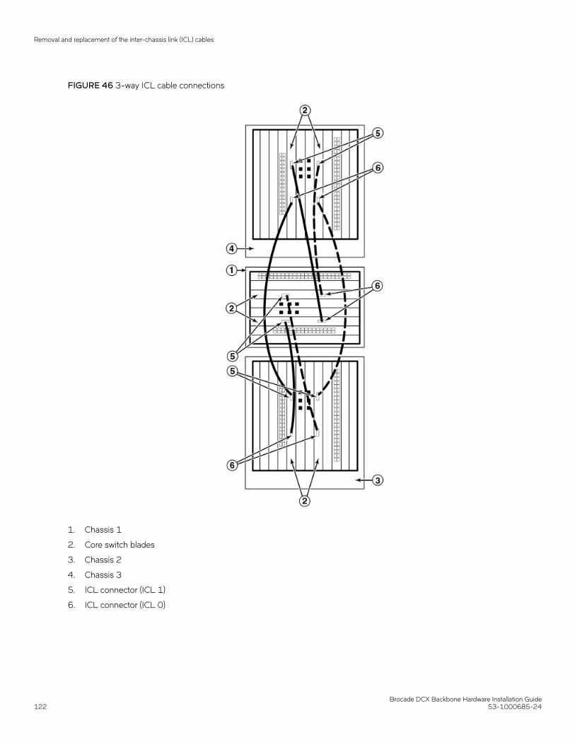
FIGURE 46 3-way ICL cable connections
1. Chassis 1
2. Core switch blades
3. Chassis 2
4. Chassis 3
5. ICL connector (ICL 1)
6. ICL connector (ICL 0)
Removal and replacement of the inter-chassis link (ICL) cables
Brocade DCX Backbone Hardware Installation Guide122 53-1000685-24

FIGURE 47 3-way ICL cable connections
1. Chassis 1
2. Core switch blades
3. Chassis 2
4. Chassis 3
5. ICL connector (ICL 1)
6. ICL connector (ICL 0)
NOTEThe same general configuration applies regardless of which backbone chassis are used. To keep all three chassis in thesame rack , any combination of DCX and DCX-4S backbones can be used except three DCX chassis.
Removal and replacement of the inter-chassis link (ICL) cables
Brocade DCX Backbone Hardware Installation Guide53-1000685-24 123

FIGURE 48 3-way ICL cable connections
1. Chassis 1
2. Core switch blades
3. Chassis 2
4. Chassis 3
5. ICL connector (ICL 1)
6. ICL connector (ICL 0)
For Fabric OS 6.4.0 and later, you can use three DCX chassis is an ICL configuration if the third chassis is in an immediatelyadjacent rack.
NOTE
Removal and replacement of the inter-chassis link (ICL) cables
Brocade DCX Backbone Hardware Installation Guide124 53-1000685-24

For clarity, the two "sets" of cables are drawn differently in Figure 46 through Figure 48. Also note that one set isconnected to only the blades in the "low order" slots (slot 3 in the DCX-4S and slot 5 in the DCX) and the other set isconnected to the blades in the "high order" slots (slot 5 in the DCX-4S and slot 8 in the DCX). Keeping the sets apart inthis manner minimizes the cable confusion.
Removal and replacement of the Brocade DCXchassisThis section describes how to remove and replace the Brocade DCX chassis (with its backplane). The basic steps are:
1. Verifying need for replacement on page 125
2. Recording critical Brocade DCX and SAN information on page 126
3. Disconnecting from network and fabric on page 129
4. Removing components from the chassis on page 130
5. Installing the replacement chassis on page 130
6. Installing components into the new chassis on page 131
7. Verifying correct operation of system on page 132
8. Reconnecting the system to the network and fabric on page 134
9. Verifying correct configuration of the fabric on page 135
NOTEThe Brocade DCX must be removed from the fabric and powered off to perform this procedure. Contact your supportprovider if you have any questions about whether the chassis requires replacement.
Time and items requiredThe chassis replacement takes approximately 3 hours.
The following items are required for the chassis replacement:
• Electrostatic discharge (ESD) grounding strap
• ESD grounding pads for protecting all blades and WWN cards
• Serial cable and workstation computer with a terminal emulator application (such as HyperTerminal for Windows systems or TIPfor Solaris systems), required only if serial console session used
• Pallet jack or hydraulic or assisted lift that raises a minimum of 140 cm (55 in.) and carries a minimum of 113 kg (250 lb)
• A surface on which to place the old chassis, such as a second lift or the pallet originally provided with the old chassis
• #2 Phillips screwdriver
Verifying need for replacementVerify that replacement of the chassis is necessary. Ensure that the components are firmly seated when troubleshooting, and contactyour support provider with any questions about whether the chassis should be replaced.
Any of the following events might indicate the need to replace the chassis:
• Visible mechanical damage to the chassis, including damage to sheet metal or card guides that prevents correct installation of ablade.
Removal and replacement of the Brocade DCX chassis
Brocade DCX Backbone Hardware Installation Guide53-1000685-24 125

• Bent or damaged connectors on the backplane (the surface inside the chassis to which the blades connect).
• One or more components (such as a power supply, blower assembly, port blade, control processor blade (CP8), core switchblade (CR8), or WWN card) do not function properly even after the component was replaced.
• The psShow or fanShow commands continue to show a faulty component even though the component was replaced.
• The slotShow command continues to show a faulty control processor (CP8), core switch (CR8), or port blade even though theblade was replaced.
Recording critical Brocade DCX and SAN informationAll commands must be entered from a CLI session (Telnet or serial) to the active CP blade unless otherwise indicated.
NOTERun supportShow , which includes most of the information in the following table and more. The customer should record thelocation of the .txt files, which are created by the customer in this procedure and are not called out in the supportShow results.
For detailed information about Fabric OS commands, refer to the Fabric OS Command Reference Manual . Use a checklist to ensurethat all required information is recorded.
TABLE 15 Critical information checklist
Checked? Data Notes
Configuration information
Location of "config-switch.txt" file
Location of "config-miscinfo.txt" file
IP address, subnet mask
WWN for Brocade DCX
SAN profile
Location of "SANbefor.txt" file
Notes regarding nsshow output
Notes regarding nsallshow output
Notes regarding switchshow output
Notes regarding fabricshow output
Output from supportshow command
Location of "spptshow.txt" file
Notes regarding supportshow output
Output from licenseshow command
License keys and other licensing data forlicensed products enabled on device.
Information about the new chassis
New factory serial number
New serial number (if available)
1. Open a Telnet session and log in to the Brocade DCX as admin. The default password is password. Enable the logging functionon your Telnet or serial console connection.
Removal and replacement of the Brocade DCX chassis
Brocade DCX Backbone Hardware Installation Guide126 53-1000685-24

2. Back up the current configuration.
NOTEIf you are using the Virtual Fabric feature, you should run configupload -vf before running the configupload commandto save the logical switch configuration.
• Enter configUpload -all ; then enter the requested information at the prompts.
This command uploads the Brocade DCX configuration to the customer-defined FTP server, making it available fordownloading. For more information about this command, refer to the Brocade Fabric OS Command Reference.
switch:admin> configuploadProtocol (scp or ftp) [ftp]: ftpServer Name or IP Address [host]: 123.123.123.123User Name [user]: Admin24File Name [config.txt]: config-switch0.txtPassword:Upload completeswitch:admin>
• Alternatively, you can save the configuration file to a Brocade USB device.
3. Record the WWN value: Enter wwn ; then copy the command output into a file named config-miscinfo.txt.
switch:admin> wwn10:00:00:60:69:00:00:0a
4. Record the IP address information.
Enter ipAddrShow-sw; then copy the command output into the config-miscinfo.txt file.
switch:admin> ipaddrshow -swSWITCHEthernet IP Address: 10.32.50.12Ethernet Subnetmask: 255.55.0.0Fibre Channel IP Address: 1.2.3.4Fibre Channel Subnetmask: 255.255.255.0CP0Ethernet IP Address: 10.32.50.10Ethernet Subnetmask: 255.55.0.0HostName : cp0Gateway Address: 10.32.40.1CP1Ethernet IP Address: 10.32.50.11Ethernet Subnetmask: 255.55.0.0HostName : cp1Gateway Address: 10.32.40.1Backplane IP address of CP0 : 10.0.0.6Backplane IP address of CP1 : 10.0.0.7switch:admin>switch:admin>
Removal and replacement of the Brocade DCX chassis
Brocade DCX Backbone Hardware Installation Guide53-1000685-24 127
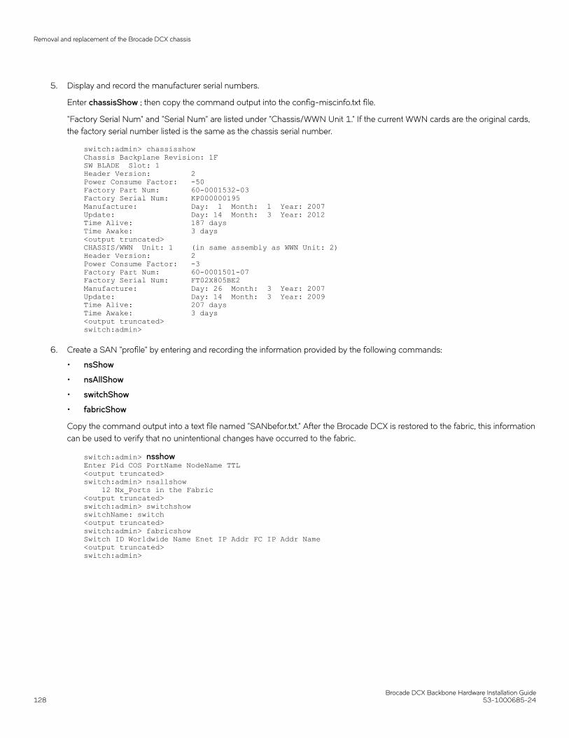
5. Display and record the manufacturer serial numbers.
Enter chassisShow ; then copy the command output into the config-miscinfo.txt file.
"Factory Serial Num" and "Serial Num" are listed under "Chassis/WWN Unit 1." If the current WWN cards are the original cards,the factory serial number listed is the same as the chassis serial number.
switch:admin> chassisshowChassis Backplane Revision: 1FSW BLADE Slot: 1Header Version: 2Power Consume Factor: -50Factory Part Num: 60-0001532-03Factory Serial Num: KP000000195Manufacture: Day: 1 Month: 1 Year: 2007Update: Day: 14 Month: 3 Year: 2012Time Alive: 187 daysTime Awake: 3 days<output truncated>CHASSIS/WWN Unit: 1 (in same assembly as WWN Unit: 2)Header Version: 2Power Consume Factor: -3Factory Part Num: 60-0001501-07Factory Serial Num: FT02X805BE2Manufacture: Day: 26 Month: 3 Year: 2007Update: Day: 14 Month: 3 Year: 2009Time Alive: 207 daysTime Awake: 3 days<output truncated>switch:admin>
6. Create a SAN "profile" by entering and recording the information provided by the following commands:
• nsShow
• nsAllShow
• switchShow
• fabricShow
Copy the command output into a text file named "SANbefor.txt." After the Brocade DCX is restored to the fabric, this informationcan be used to verify that no unintentional changes have occurred to the fabric.
switch:admin> nsshowEnter Pid COS PortName NodeName TTL<output truncated>switch:admin> nsallshow 12 Nx_Ports in the Fabric<output truncated>switch:admin> switchshowswitchName: switch<output truncated>switch:admin> fabricshowSwitch ID Worldwide Name Enet IP Addr FC IP Addr Name<output truncated>switch:admin>
Removal and replacement of the Brocade DCX chassis
Brocade DCX Backbone Hardware Installation Guide128 53-1000685-24

7. Enter licenseShow; then copy the command output into a text file named "licenseshow.txt."
switch:admin> licenseshowS9bddb9SQbTAceeC:Fabric licenseeezeRRySff0fSe:Remote Switch licensebzbzRcbcSc0c0SY:Remote Fabric licensedSeR9RcSeeTfSAq:Extended Fabric licenseRyeSzRScycTzfT09:Entry Fabric licenseRyeSzRScycazfT0G:Trunking licenseRyeSzRScycS0fT09:4 Domain Fabric license
8. Enter supportShow ; then copy the command output into a text file named "spptshow.txt."
NOTEThe supportShow command has a very long output and time for completion. It may last 20 minutes or longerdepending on the size of the SAN.
This file provides a backup of all the information that might be required by Technical Support. The information can be used afterthe Brocade DCX is restored to the fabric to verify that no unintentional changes have occurred to the fabric.
switch:admin> supportshowversion: 6.0.0<output truncated>switch:admin>
9. Record the cable connections between the Brocade DCX and the target device and ports (Cable routing table on page 135).
Disconnecting from network and fabric1. Shut down the Brocade DCX using the sysShutdown command.
switch:admin> sysshutdownThis command will shutdown the operating systems on your switch.You are required to power-cycle the switch in order to restore operation.Are you sure you want to shutdown the switch [y/n]?yHA is disabledStopping blade 1 Shutting down the blade....Stopping blade 4 Shutting down the blade....Stopping blade 10 Shutting down the blade....Broadcast message from root (pts/1) Tue Jul 18 14:23:06 2006...The system is going down for system halt NOW !!
DANGERTurn off the power switches and disconnect the power cords.
2. Power off the chassis by flipping all AC power switches to the off position. (The power supply status LED should turn off.)
3. Remove the power cords from the power supplies and the power outlets.
4. Label the cables connected to all blades and record the connections in Cable routing table on page 135 and additional copies ifnecessary.
5. Remove the chassis door (Removal and replacement of the chassis door on page 83).
Removal and replacement of the Brocade DCX chassis
Brocade DCX Backbone Hardware Installation Guide53-1000685-24 129

6. Disconnect the cables from the port blades and set them aside. The mSFP, SFP, SFP+, or XFP transceivers can be left in theport blades or removed.
7. Disconnect all cables from the CP8 and CR8 blades.
8. Disconnect any ICL cables.
Removing components from the chassisATTENTION
Follow electrostatic discharge (ESD) precautions when removing components. Wear a wrist grounding strap connected to chassis ground(if the device is plugged in) or a bench ground.
NOTEDo not remove WWN cards from the chassis as new WWN cards are preinstalled in the replacement chassis. Do not replace theWWN cards in the replacement chassis with the old WWN cards as this will result in licensing and return materials authorization(RMA) issues for your product. The original license will be transferred to the replacement chassis, based on the licenseidentification (LID) of the new, preinstalled WWN card, through the RMA process. You should be provided a license for the newchassis through email. If you have not received this, contact your Brocade support representative.
1. Remove the chassis door (Removal and replacement of the chassis door on page 83) if not already done.
2. Remove the cable management comb (Removal and replacement of the cable management comb on page 84).
3. Remove the port blades or filler panels (Removal and replacement of the port, application, and encryption blades on page 86and Removal and replacement of the blade filler panel on page 89).
4. Remove the core switch blades (CR8) (Removal and replacement of the core switch blade (CR8) on page 97).
5. Remove the control processor blades (CP8) (Removal and replacement of the control processor blade (CP8) on page 91).
6. Remove the power supplies or filler panels (Removal and replacement of the power supply on page 100).
7. Remove the blower assemblies (Removal and replacement of the blower assembly on page 103).
Installing the replacement chassisNOTEUse safe lifting practices when moving the product. (C015)
ATTENTIONA fully populated Brocade DCX (eight FC8-64 port cards, 512 ports) weighs approximately 159.2 kg (351 lb) and requires ahydraulic or assisted lift to install it.
NOTEIf the Brocade DCX is installed in a cabinet, ensure that the cabinet is balanced and secured mechanically and that the removaland installation procedure will not compromise cabinet stability.
1. If the chassis is in a cabinet, remove it from the cabinet, remove the rack mount hardware, and save the hardware for use withthe new chassis.
2. Place the chassis on a lift or on the shipping pallet provided with the original chassis.
Removal and replacement of the Brocade DCX chassis
Brocade DCX Backbone Hardware Installation Guide130 53-1000685-24

3. Unpack the new chassis:
a) Cut the bands that encircle the packaging.
b) Remove the lid and the kits and foam from the top of the chassis.
c) Lift the cardboard box off the chassis and remove the plastic bag from around the chassis.Save the packing materials foruse when returning the old chassis.
d) Leave the chassis on top of the plastic shipping tray if the chassis must be transported to the installation location.
NOTEThe Brocade DCX packaging does not incorporate a wood pallet and pallet brackets. The chassis sits on top of aplastic shipping tray.
4. Use a pallet jack or other assisted lift to transport the new chassis to the installation area. Doorways must be wider than 91 cm(36 in.) to accommodate the chassis on the pallet.
5. Use a lift to raise the chassis to the correct level. If installing the chassis in a cabinet, follow the instructions provided by the rackkit manufacturer.
Installing components into the new chassisNOTEFollow electrostatic discharge (ESD) precautions when installing new components. Wear a wrist grounding strap connected tochassis ground (if the device is plugged in) or a bench ground.
1. Record the chassis serial number, SKU, and WWN printed on the chassis label. This label is located on the lower right corner ofthe chassis on the port side.
You may need this information to transfer licenses to the new chassis.
2. Replace the blower assemblies (Removal and replacement of the blower assembly on page 103).
3. Replace the power supplies or filler panels (Removal and replacement of the power supply on page 100).
4. Replace the control processor blades (CP8) (Removal and replacement of the control processor blade (CP8) on page 91).
5. Replace the core switch blades (CR8) (Removal and replacement of the core switch blade (CR8) on page 97).
6. If ICL cables are not used, insert EMI plugs in the ICL sockets in the core switch blades (CR8).
7. Replace the port blades or filler panels (Removal and replacement of the port, application, and encryption blades on page 86and Removal and replacement of the blade filler panel on page 89).
8. Replace the cable management comb (Removal and replacement of the cable management comb on page 84).
9. Connect the power cords to the power supplies and the power outlets.
10. Replace the chassis door (Removal and replacement of the chassis door on page 83).
11. Power on the Brocade DCX (Providing power to the DCX Backbone on page 52).
The Brocade DCX performs a power-on self-test (POST). The POST takes a minimum of three minutes and is complete whenLED activity returns to standard state.
12. Verify that the Brocade DCX is powered on and POST is complete (all power LED indicators on the blades should be a steadygreen).
13. Verify that all components are functioning correctly by checking their LEDs. If the LEDs do not indicate correct operation, tryreinstalling the corresponding component.
Removal and replacement of the Brocade DCX chassis
Brocade DCX Backbone Hardware Installation Guide53-1000685-24 131

Downloading the configurationOnce the chassis and its various components have been reassembled and powered back on, use the configDownload command torestore the original configuration. The configDownload command can be entered through a Telnet or serial session, but the BrocadeDCX must have an Ethernet connection to the server name or IP address of the host for the download process to complete. For moreinformation, refer to the help configdownload command or the Brocade Fabric OS Command Reference.
1. Log in to the Brocade DCX as admin.
switch:admin> loginlogin: adminpassword: xxxxxxxxswitch:admin>
NOTEIf you are using the Virtual Fabric feature, you must run configdownload -vfbefore running the configdownloadcommand to restore the logical switch configuration.
2. Enter the configDownload command.
switch:admin> configdownload -allServer Name or IP Address [host]: 123.123.123.123User Name [None]: Admin24File Name [config.txt]: config-switch.txtPassword: xxxxxxxxdownload completeswitch:admin>
3. Reboot the DCX.
Verifying correct operation of system1. Log in to the Brocade DCX as admin.
switch:admin> loginlogin: adminpassword: xxxxxxxxswitch:admin>
2. Enter the slotShow -m command and verify that all the installed cards are detected and that their status is operational (enabled).
switch:admin> slotShow -mSlot Blade Type ID Model Name Status-------------------------------------------- 1 AP BLADE 75 FX8-24 ENABLED 2 AP BLADE 75 FX8-24 ENABLED 3 SW BLADE 51 FC8-48 ENABLED 4 UNKNOWN VACANT 5 CORE BLADE 52 CR8 ENABLED 6 CP BLADE 50 CP8 ENABLED 7 CP BLADE 50 CP8 ENABLED 8 CORE BLADE 52 CR8 ENABLED 9 SW BLADE 51 FC8-48 ENABLED 10 SW BLADE 51 FC8-48 ENABLED 11 SW BLADE 51 FC8-48 ENABLED 12 UNKNOWN VACANTswitch:admin>
Removal and replacement of the Brocade DCX chassis
Brocade DCX Backbone Hardware Installation Guide132 53-1000685-24

3. Verify that the Brocade DCX is functioning correctly by entering switchShow or switchStatusShow .
This switchShow command displays Brocade DCX and port status information.
switch:admin> switchshowswitchName: switchswitchType: 62.1switchState: OnlineswitchMode: NativeswitchRole: SubordinateswitchDomain: 11switchId: fffc0bswitchWwn: 10:00:00:05:1e:39:59:67zoning: OFFswitchBeacon: OFFblade3 Beacon: OFFblade5 Beacon: OFFblade8 Beacon: OFFblade10Beacon: OFFIndex Slot Port Address Media Speed State Proto=========================================================== 32 3 0 0b2000 id N4 Online L-Port 5 public 33 3 1 0b2100 __ N8 No_Module 34 3 2 0b2200 __ N8 No_Module 35 3 3 0b2300 __ N8 No_Module 36 3 4 0b2400 id N4 Online F-Port10:00:00:00:c9:51:00:2d 37 3 5 0b2500 __ N8 No_Moduleswitch:admin>
4. Verify that all the IP address information is correct by entering ipAddrShow and checking the results against the IP informationrecorded in the config-miscinfo.txt file.
switch:admin> ipaddrshowSWITCHEthernet IP Address: 10.32.50.12Ethernet Subnetmask: 255.55.0.0Fibre Channel IP Address: 1.2.3.4Fibre Channel Subnetmask: 255.255.255.0CP0Ethernet IP Address: 10.32.50.10Ethernet Subnetmask: 255.55.0.0HostName : cp0Gateway Address: 10.32.40.1CP1Ethernet IP Address: 10.32.50.11Ethernet Subnetmask: 255.55.0.0HostName : cp1Gateway Address: 10.32.40.1Backplane IP address of CP0 : 10.0.0.5Backplane IP address of CP1 : 10.0.0.6switch:admin>switch:admin>
Removal and replacement of the Brocade DCX chassis
Brocade DCX Backbone Hardware Installation Guide53-1000685-24 133

Reconnecting the system to the network and fabricSee the cable routing information recorded in Cable routing table on page 135 for the following steps.
1. Connect the CP blades to the local area network.
a) Insert the appropriate Ethernet cables into each Ethernet port.
b) Connect the other ends to an Ethernet 10/100 Base-T LAN, if not already connected.
NOTEThe Brocade DCX can be accessed by remote connection using any of the available management tools, such asTelnet or Web Tools. Ensure that the Brocade DCX is not modified using other connections during the rest of thisprocedure.
2. Reconnect the transceivers and cables to the port blades:
NOTEThe ports and cables used in trunking groups must meet specific requirements. For a list of these requirements, referto theBrocade Fabric OS Administration Guide.
a) Position one of the transceivers so that the key is oriented correctly to the port and insert the transceiver into the port until itis firmly seated and the latching mechanism clicks.
b) Select the cable that corresponds to the port and position it so that the key (the ridge on one side of the cable connector) isaligned with the slot in the transceiver. Insert the cable into the transceiver until the latching mechanism clicks.
c) Repeat the above two sub-steps for the remaining ports.
ATTENTIONDo not route cables in front of the air exhaust vent (located on the upper port side of the chassis).
d) Organize the cables as required.
Removal and replacement of the Brocade DCX chassis
Brocade DCX Backbone Hardware Installation Guide134 53-1000685-24

Verifying correct configuration of the fabricCopying the command outputs from this section into a file is recommended.
1. Create an "after" SAN profile by entering the following commands and copying the output to a text file named SANafter.txt:
• nsShow
• nsAllShow
• switchShow
• fabricShow
• lscfg --show (if using the Virtual Fabric feature)
switch:admin> nsshowType Pid COS PortName NodeName TTL(sec) N 020f00; 3;10:00:00:01:73:00:29:46;10:00:00:01:73:00:29:46; na Fabric Port Name: 20:0f:00:60:69:90:03:f0<output truncated>switch:admin> nsallshow{ 020f00 021fda 021fdc 021fe0 021fe15 Nx_Ports in the Fabric}switch:admin> switchshowswitchName: rsl8-st03-dcx-01<output truncated>switch:admin> fabricshowSwitch ID Worldwide Name Enet IP Addr FC IP Addr Name<output truncated>switch:admin>lscfg --showCreated switches: 128(ds) 1 2(bs)Port 0 1 2 3 4 5 6 7 8 9-------------------------------------------------------------------FID 1 | 1 | 1 | 1 | 1 | 128 | 128 | 128 | 128 | 128 |<output truncated>switch:admin>
2. Determine any differences between the information in the SANafter.txt file and the information in the SANbefor.txt file createdearlier. In particular, look for differences in the following:
• Device types
• Number of devices
• ISL and port states
• Number of switches in the fabric
3. Resolve any issues or unintentional changes to the Brocade DCX or fabric:
• If there are any mechanical problems, try reseating the associated component.
• If the configuration information is not correct for the Brocade DCX, modify as required.
• If other issues exist, contact your support provider.
Cable routing tableThe following table is a 64-port template for a cable routing table. Make copies of the table to cover the total number of ports in theBrocade DCX.
TABLE 16 Cable routing table for Brocade DCX (64 ports shown)
Slot/port Cable labels Connected device Slot/port of device
Slot Port Switch end Device end
Removal and replacement of the Brocade DCX chassis
Brocade DCX Backbone Hardware Installation Guide53-1000685-24 135

TABLE 16 Cable routing table for Brocade DCX (64 ports shown) (continued)
Slot/port Cable labels Connected device Slot/port of device
0
1
2
3
4
5
6
7
8
9
10
11
12
13
14
15
16
17
18
19
20
21
22
23
24
25
26
27
28
29
30
31
32
33
34
35
36
37
38
39
40
Removal and replacement of the Brocade DCX chassis
Brocade DCX Backbone Hardware Installation Guide136 53-1000685-24

TABLE 16 Cable routing table for Brocade DCX (64 ports shown) (continued)
Slot/port Cable labels Connected device Slot/port of device
41
42
43
44
45
46
47
48
49
50
51
52
53
54
55
56
57
58
59
60
61
62
63
Removal and replacement of the Brocade DCX chassis
Brocade DCX Backbone Hardware Installation Guide53-1000685-24 137

Brocade DCX Backbone Hardware Installation Guide138 53-1000685-24

Application and Encryption Blades• Introduction....................................................................................................................................................................................................... 139• FS8-18 blade..................................................................................................................................................................................................139• FX8-24 blade..................................................................................................................................................................................................139• FCOE10-24 blade........................................................................................................................................................................................141
IntroductionThis appendix provides details about the application and encryption blades that are available optionally for the Brocade DCX. Contactyour Brocade DCX supplier for additional information.
FS8-18 bladeThe FS8-18 encryption blade is a high performance 16 port auto-sensing blade with data cryptographic (encryption/decryption) anddata compression capabilities designed for enterprises to secure their data against theft or unauthorized use and to compress tape datafor maximum utilization of tape media. The encryption blade is a network-based solution that secures data-at-rest for heterogeneoustape drives, disk array LUNs, and virtual tape libraries.
The FS8-18 blade provides the following major features:
• 16 auto-sensing F, FL, E, EX, and M ports at 8 Gbps FC ports
• 16 SFP media interfaces
• Encryption engines
• Key management/generation
• Key management with these hardware interfaces:
– Two 1000Base copper type media interfaces– One smart card interface
• Security supervisor tamper detection and response capability
• CC (Common Criteria) EAL-3 compliance
FX8-24 bladeThe FX8-24 blade has 12 external Fibre Channel (FC) SFP ports supporting the Fibre Channel Routing Services and 10 external 1Gigabit Ethernet (GbE or GE) SFP ports supporting the Fibre Channel over IP (FCIP) feature. There are also 2 licensable external 10Gigabit Ethernet (10GbE or 10GE) SFP ports supporting FCIP. It operates with the Brocade Fabric Operating System and cancommunicate with another FX8-24 or a Brocade 7800 for both Fibre Channel Routing Services and FCIP, or a Brocade AP7420 forFibre Channel Routing Services.The GbE ports on the FX8-24 are not compatible with the GbE ports on the FR4-18i blade or theBrocade 7500 switch.
NOTEThe port diagram on the front panel uses the abbreviations GE for 1 GbE ports and 10GE for 10 GbE ports.
Brocade DCX Backbone Hardware Installation Guide53-1000685-24 139
The FX8-24 operates in one of three modes: 1) ten 1GbE ports, 2) ten 1GbE ports and one 10 GbE port, or 3) two 10 GbE portsdepending on licensing and subsequent configuration of GbE port mode. If operating in 10GbE mode, the other end of the circuit mustalso be an FX8-24 operating in either 10GbE mode or dual mode with the corresponding VE_ports in 10GbE mode. All GbE ports onthe blade can be configured to work with either copper or optical SFPs.
The FX8-24 blade is intended as a platform for FCIP and Fibre Channel Routing Services. Refer to the Brocade Fabric OSAdministration Guide for information on configuring these features.
The FX8-24 blade provides the following hardware features:
• Twelve autosensing FC ports with link speeds of 1, 2, 4 or 8 Gbps
• Ten GbE ports supporting FCIP with fixed link speed at 1 Gbps
• Two 10 GbE ports (licensable) supporting FCIP with fixed link speed at 10 Gbps
The FX8-24 blade also provides the following functionality features:
• FCIP
• Compression (on FC frames before FCIP encapsulation)
• FC Routing (licensable)
• FCIP Trunking (licensable) with network-based failure recovery (failover only) and load balancing
• Multiple circuits per trunk:
– Four per trunk through the GbE ports– Ten per trunk through the 10 GbE ports
• SO-TCP with reorder resistance
• FastWrite over FCIP
• Tape pipelining over FCIP
• FICON XRC emulation and tape pipelining over FCIP (licensable)
• FICON CUP (licensable)
• Virtual E_ports
• FCIP QoS
• Support for 200 ms RTT (on a limited number of GbE ports)
• Adaptive Rate Limiting (licensable)
• TCP performance graphing in Web Tools
• FCIP Tunnels:
– A maximum of 10 FCIP Tunnels for all GbE ports.– Four tunnels maximum per GbE port.– Two 10 GbE ports can support up to ten FCIP tunnels each.– Each FCIP tunnel is represented and managed as a virtual Fibre Channel E_Port.– Fibre Channel Routing Services can be used over the FCIP link.– The Link Cost is equal to the sum of all established/low metric (or currently active) circuits’ MAX rates in the tunnel.– Fabrics connected through FCIP merge if the ports are configured as VE_Ports, and do not merge if they are configured as
VEX_Ports. If VE_Ports are used in a Fibre Channel Routing Services backbone fabric configuration, then the backbonefabric merges, but the EX_Port-attached edge fabrics do not merge. For more information refer to the Brocade Fabric OSAdministration Guide.
• Up to three FC trunking groups. The three groups are defined as:
– Trunk group 0: FC ports 0, 1– Trunk group 1: FC ports 6, 7
FX8-24 blade
Brocade DCX Backbone Hardware Installation Guide140 53-1000685-24

– Trunk group 2: FC ports 2, 3, 4, 5, 8, 9, 10, 11
A RoHS-compliant version of the FX8-24 blade is available. To determine if this blade is installed, enter the chassisshow command.Output for the Factory Part Number will be 60-1003135-XX. Downgrading to these FOS versions is also not recommended if thisblade is installed.
FCOE10-24 bladeThe FCOE10-24 blade has 24 Fibre Channel over Ethernet (FCoE) ports that enable the transmission of FC frames over an Ethernetnetwork via encapsulation in standard Ethernet packets. This is enabled by adherence to Converged Enhanced Ethernet (CEE) standards,a low latency, lossless Ethernet standard. This does not require dedicated Ethernet lines, but rather can make use of existing Ethernetinfrastructure to reduce costs.
NOTEThis blade cannot be used in the same chassis with an FC8-48E, FC8-64, FC16-48, FC16-64 port blades or any of theapplication blades (FX8-24).
The FCOE10-24 blade supports only optical cabling and transceivers (SFP+).
There are no licensing requirements for functionality on this blade.
The FCOE10-24 blade provides the following hardware features:
• 24 FCoE ports operating at 10 Gbps
• 32 FC ports operating at 8 Gbps through the backplane
• Hot pluggable
• I2C Management interface through the backplane
• JTAG support
• Blade power and status LEDs
• Link status LEDs per port
The FCOE10-24 blade also provides the following functionality features:
• FCoE switching
• CEE switching
• Layer 2 Ethernet protocols STP/MSTP/RSTP, 802.1q, and Link Aggregation (802.1ad)
• Standard Ethernet encapsulation
• End of row deployment
NOTEWith the switch in online state, if all the FCOE ports are shutdown, offline diags will continue to run. After this, the blade will be ininoperable state and you need to issue slotpoweroff and slotpoweron to recover.
Refer to the Brocade Fabric OS Administration Guide for information on configuring these features.
FCOE10-24 blade
Brocade DCX Backbone Hardware Installation Guide53-1000685-24 141

Brocade DCX Backbone Hardware Installation Guide142 53-1000685-24

Diagnostics and Troubleshooting• Introduction....................................................................................................................................................................................................... 143• Obtaining chassis and component status............................................................................................................................................143• Interpreting POST and boot results........................................................................................................................................................144• Diagnostics........................................................................................................................................................................................................145• Troubleshooting...............................................................................................................................................................................................145• Powering off the Brocade DCX.................................................................................................................................................................147
IntroductionFor information about troubleshooting the entire fabric, refer to the Fabric OS Troubleshooting and Diagnostics Guide.
The Brocade DCX includes a number of diagnostic aids to assist with troubleshooting, including LEDs on the hardware, commands thatdisplay current status, diagnostic tests for hardware and software, and error messages. In addition, a number of managing andmonitoring features are available, such as Fabric Manager, Web Tools, Fabric Watch, and Advanced Performance Monitoring.
If the Brocade DCX does not operate as expected, the following steps can be taken to diagnose the problem:
• Check the LEDs and see the LED tables (Monitoring System Components on page 63) for interpretation and recommendedactions.
• Review the results of the last POST run by the Brocade DCX (Interpreting POST and boot results on page 144).
• Review the error logs. (Refer to the Fabric OS Troubleshooting and Diagnostics Guide for more information).
– Review RASlog entries.– Type the sensorShow command to determine the status of the hardware components.– Run diagnostic tests (Diagnostics on page 145).– Reboot the Brocade DCX or power the entire chassis off and then on (Powering off the Brocade DCX on page 147 and
Providing power to the DCX Backbone on page 52).
If the problem is still unresolved after these steps, contact your support provider. The information required by your support provider islisted under Contacting Brocade Technical Support on page 11.
Obtaining chassis and component statusThe CLI commands in the following table provide status and environmental information about the chassis and its components. Thesecommands provide information only, and they do not interrupt traffic flow. For more information about these commands, refer to theBrocade Fabric OS Command Reference.
TABLE 17 Environmental status and maintenance commands
Command Information displayed
sensorShow Temperature readings for the port blades
Temperature readings for the CP blades
Status and RPM of all operational fans
Status of all operational power supplies
tempShow Temperature readings for the port blades
Temperature readings for the CP blades
Brocade DCX Backbone Hardware Installation Guide53-1000685-24 143

TABLE 17 Environmental status and maintenance commands (continued)
Command Information displayed
psShow Status of all operational power supplies
fanShow Status and RPM of all operational fans
chassisShow Serial number, time awake, and additional information about eachcomponent
slotShow Slot occupancy
errShowerrDump System error log. Refer to the Brocade Fabric OS Message Reference formore information on the messages in this log.
Interpreting POST and boot resultsThe Brocade DCX performs Power-On Self-Test (POST) by default each time the chassis is powered on, rebooted, or reset. The BrocadeDCX can be rebooted using the reboot (to reboot each CP individually) or fastBoot commands. The fastBoot command reboots theswitches without running POST. If the active CP blade is rebooted, it fails over to the standby CP blade.
POSTThe Brocade DCX automatically performs POST each time it is powered on or reset.
To verify that POST has completed without error:
• Verify that all LEDs return to a normal state after POST completes (Monitoring System Components on page 63).
If one or more LEDs do not return to a normal state, and this is not due to the Brocade DCX being set to beacon, refer to therelevant LED table to identify and correct the problem. For port blades, and CP and core switch blades, the slotShow commandcan be used to check the status of the slots. For information about turning beaconing on or off, refer to the Brocade Fabric OSAdministration Guide.
• Verify that the switch prompt displays when POST completes.
If it does not display, POST was not successfully completed. Contact the Brocade DCX supplier for support.
• Review the system error log using the errShow or errDump commands.
Any errors detected during POST are written to the system log, which is accessible through the errShow command. Forinformation about error messages, refer to the Brocade Fabric OS Message Reference.
POST includes the following steps:
1. Preliminary POST diagnostics are run.
2. Operating system is initialized.
3. Hardware is initialized.
4. Diagnostic tests are run on several functions, including circuitry, port functionality, ability to send and receive frames, all aspectsof memory, parity, statistics counters, and serialization.
BootIn addition to POST, boot includes the following steps after POST is complete:
1. Universal port configuration is performed.
2. Links are initialized.
Interpreting POST and boot results
Brocade DCX Backbone Hardware Installation Guide144 53-1000685-24

3. Fabric is analyzed. If any ports are connected to other switches, the Brocade DCX participates in a fabric configuration.
4. The Brocade DCX obtains a domain ID and assigns port addresses.
5. Unicast routing tables are constructed.
6. Normal port operation is enabled.
DiagnosticsDiagnostic tests are automatically run during POST to check the status of the Brocade DCX. Any error messages generated duringPOST are sent to the error logs and to the serial console, if connected.
Diagnostic tests can also be run manually to test and troubleshoot the hardware and the firmware, including internal connections andcircuitry, transceivers, and port cables. However, diagnostic tests are generally intended for use by support personnel.
NOTEError messages do not necessarily indicate that the Brocade DCX requires maintenance.
Each diagnostic test can be implemented by entering the related command through a Telnet or serial session. For a list of diagnostictests and commands, refer to theBrocade Fabric OS Administration Guide
All diagnostic tests are run at link speeds of 1, 2, 4, and 8 Gbps. They might temporarily lock the transmit and receive speeds to aspecific speed. Some diagnostic tests require interconnecting the ports to each other or using loopback plugs. If ports areinterconnected, the media (cables and transceivers) at each end of the connection must be of the same type. For example, shortwavelength media must be connected to short wavelength media, and likewise with long wavelength media and copper media.
For more information about diagnostic tests and how to run them, refer to the Brocade Fabric OS Administration Guide and the BrocadeFabric OS Command Reference. For information about system error messages (errShow or errDump ), refer to the Fabric OSTroubleshooting and Diagnostics Guide .
TroubleshootingThe following table provides a list of issues, possible causes, and recommended actions.
TABLE 18 Troubleshooting the Brocade DCX
Issue Possible cause Recommended action
Entire chassis powers off automatically. Power supplies are inadequate to support theinstalled components.
Add an additional power supply.
Several or all components are not operating. One or both power cables may not beconnected to a live source.
Ensure that both power cables are connected tolive outlets.
One or both AC power switches might be off. Ensure that both AC power switches are on (ACswitches light up green when on).
Serial connection is faulty or serial port logs haveincorrect or missing information.
Serial cable is not connected correctly. Ensure that the cable is firmly connected toworkstation computer and to the Brocade DCX.
Terminal emulator application parameters arenot set correctly.
Ensure that the terminal emulator application isconfigured as follows: 9600 bits per second, 8databits, no parity, 1 stop bit, no flow control.
Serial port might be incompatible (only RS-232is supported).
Ensure that the Brocade DCX is connected to anRS-232 port. RS-423 serial ports mightexperience difficulties due to corner-caseincompatibilities of the standards.
Troubleshooting
Brocade DCX Backbone Hardware Installation Guide53-1000685-24 145

TABLE 18 Troubleshooting the Brocade DCX (continued)
Issue Possible cause Recommended action
Pins on the serial cable or serial port might bedamaged.
Remove the cable and inspect the pins on thecable and in the serial port. Do not reinstall if thepins on either component have any visibledamage, as this could damage the pins on theother component. Replace the components asrequired.
CP Ethernet link speed is different than expectedor a link cannot be established.
There might be a conflict with the CP Ethernetlink speed negotiation set up by the network.
Specify the CP Ethernet link speed by enteringthe ifModeSet command.
For more information about Ethernetconnectivity to the Brocade DCX, refer to theLAN guidelines provided through theMyBrocade Web site.
Configuration data is inaccurate or cannot beaccessed.
Chassis was powered off/on while a WWN cardwas uninstalled or failed.
Install an operational WWN card and power thesystem off/on again.
The Brocade DCX was rebooted while a WWNcard was uninstalled or failed.
Initial set up results in IP address/Domain IDconflict.
The Brocade DCX was connected to the fabricbefore being configured.
See Logging In and Configuring the DCXBackbone on page 51 and the Brocade FabricOS Administration Guide for configurationinformation.
LEDs on one or more components are changingrapidly or do not indicate a healthy state.
The Brocade DCX might be booting or runningPOST.
Verify that boot and POST are complete. TheBrocade DCX requires a minimum of 3 minutes,usually, after power-on to complete POST.
Beaconing might be on for the entire BrocadeDCX or for individual components.
Determine whether beaconing is on by enteringthe switchShow command and determinewhether switch beaconing or blade beaconing ison.
Individual components might have failed. See the LED tables in Monitoring SystemComponents on page 63 for interpretation andrecommended actions.
Pins on the components might be damaged. Remove the component from the chassis andinspect the pins on the component and insidethe chassis. Do not reinstall if pins on eithercomponent are damaged, as this could damagepins on other components. Replace the parts asrequired.
None of the LEDs on a component are on. Component might not be seated correctly. Ensure that the Brocade DCX has power and thecomponent is firmly seated. If the problemcontinues, enter the sensorShow command todetermine the component status. If thecomponent is a CP blade or port blade, enter theslotShow command to determine the status.
Component might have failed. Replace the component as necessary.
CP blades are failing over frequently. A third-party application has a memory leak. Check application for memory leaks.
There is excessive serial port activity. Ensure that the serial port activity remains belowspecified amount.
CP blade is attached to an Ethernet with hightraffic loads.
Ensure that the Ethernet traffic remains belowspecified amount
Chassis is overheated. Enter the tempshow and sensorShowcommands to check internal temperature. Ifcomponents are overheating, shut down portblades as necessary to return the temperature tooperating range.
Troubleshooting
Brocade DCX Backbone Hardware Installation Guide146 53-1000685-24
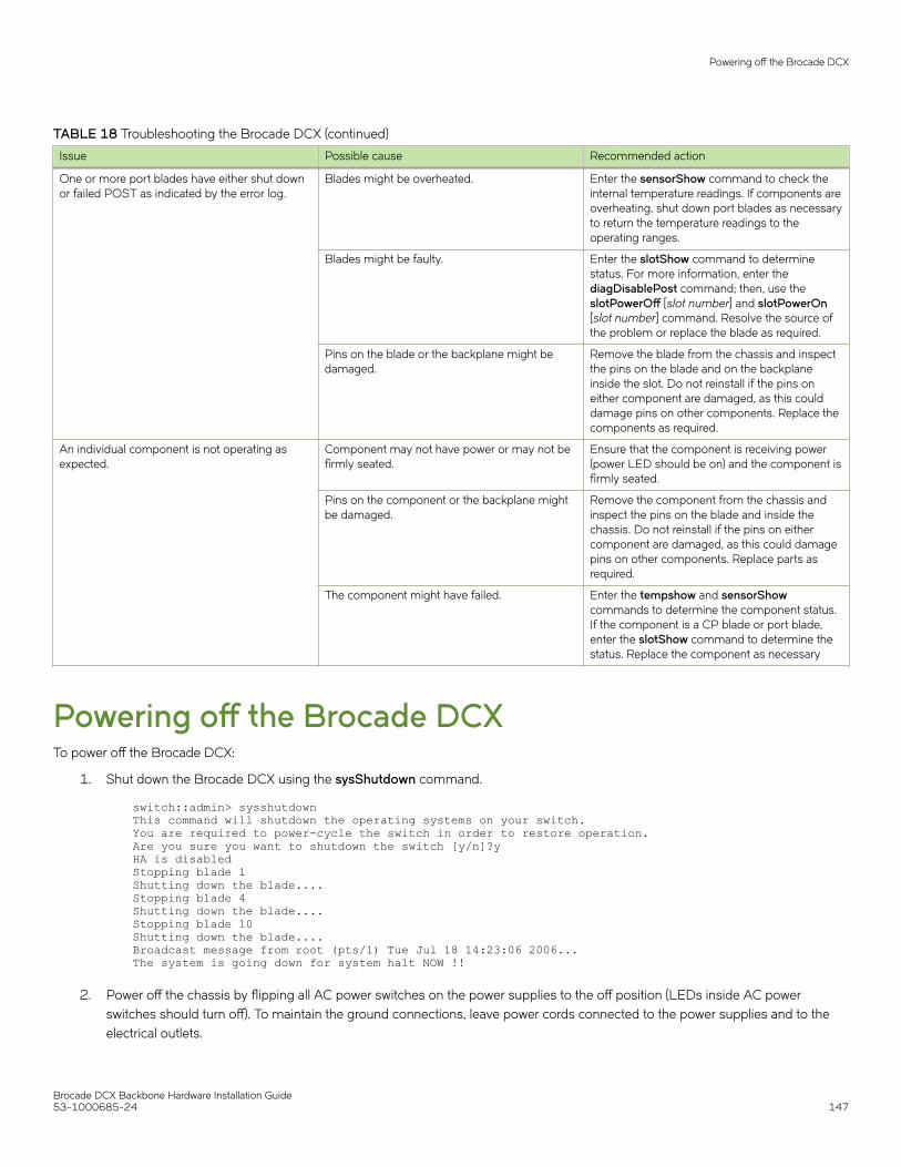
TABLE 18 Troubleshooting the Brocade DCX (continued)
Issue Possible cause Recommended action
One or more port blades have either shut downor failed POST as indicated by the error log.
Blades might be overheated. Enter the sensorShow command to check theinternal temperature readings. If components areoverheating, shut down port blades as necessaryto return the temperature readings to theoperating ranges.
Blades might be faulty. Enter the slotShow command to determinestatus. For more information, enter thediagDisablePost command; then, use theslotPowerOff [slot number] and slotPowerOn[slot number] command. Resolve the source ofthe problem or replace the blade as required.
Pins on the blade or the backplane might bedamaged.
Remove the blade from the chassis and inspectthe pins on the blade and on the backplaneinside the slot. Do not reinstall if the pins oneither component are damaged, as this coulddamage pins on other components. Replace thecomponents as required.
An individual component is not operating asexpected.
Component may not have power or may not befirmly seated.
Ensure that the component is receiving power(power LED should be on) and the component isfirmly seated.
Pins on the component or the backplane mightbe damaged.
Remove the component from the chassis andinspect the pins on the blade and inside thechassis. Do not reinstall if the pins on eithercomponent are damaged, as this could damagepins on other components. Replace parts asrequired.
The component might have failed. Enter the tempshow and sensorShowcommands to determine the component status.If the component is a CP blade or port blade,enter the slotShow command to determine thestatus. Replace the component as necessary
Powering off the Brocade DCXTo power off the Brocade DCX:
1. Shut down the Brocade DCX using the sysShutdown command.
switch::admin> sysshutdownThis command will shutdown the operating systems on your switch.You are required to power-cycle the switch in order to restore operation.Are you sure you want to shutdown the switch [y/n]?yHA is disabledStopping blade 1 Shutting down the blade....Stopping blade 4 Shutting down the blade....Stopping blade 10 Shutting down the blade....Broadcast message from root (pts/1) Tue Jul 18 14:23:06 2006...The system is going down for system halt NOW !!
2. Power off the chassis by flipping all AC power switches on the power supplies to the off position (LEDs inside AC powerswitches should turn off). To maintain the ground connections, leave power cords connected to the power supplies and to theelectrical outlets.
Powering off the Brocade DCX
Brocade DCX Backbone Hardware Installation Guide53-1000685-24 147

Brocade DCX Backbone Hardware Installation Guide148 53-1000685-24

Port Numbering TemplatePrint or copy the following templates in this appendix and use them to document the port numbering pattern for the Brocade DCX.These templates show the following components:
• FC8-16 port blade (Figure 49)
• FC8-32 port blade (Figure 50)
• FC8-48 port blade (Figure 51)
• FC8-64 high density port blade (Figure 52)
• FS8-18 encryption blade (Figure 53)
• FX8-24 extension blade (Figure 54)
• FCOE10-24 FCoE blade (Figure 55)
Brocade DCX Backbone Hardware Installation Guide53-1000685-24 149

FIGURE 49 FC8-16 port blade
1. Blade Power LED
2. Blade Status LED
3. FC ports 0-15 (bottom to top)
Brocade DCX Backbone Hardware Installation Guide150 53-1000685-24

FIGURE 50 FC8-32 port blade
1. Blade Power LED
2. Blade Status LED
3. FC ports 0-15 (bottom to top)
4. FC ports 16-31 (bottom to top)
Brocade DCX Backbone Hardware Installation Guide53-1000685-24 151
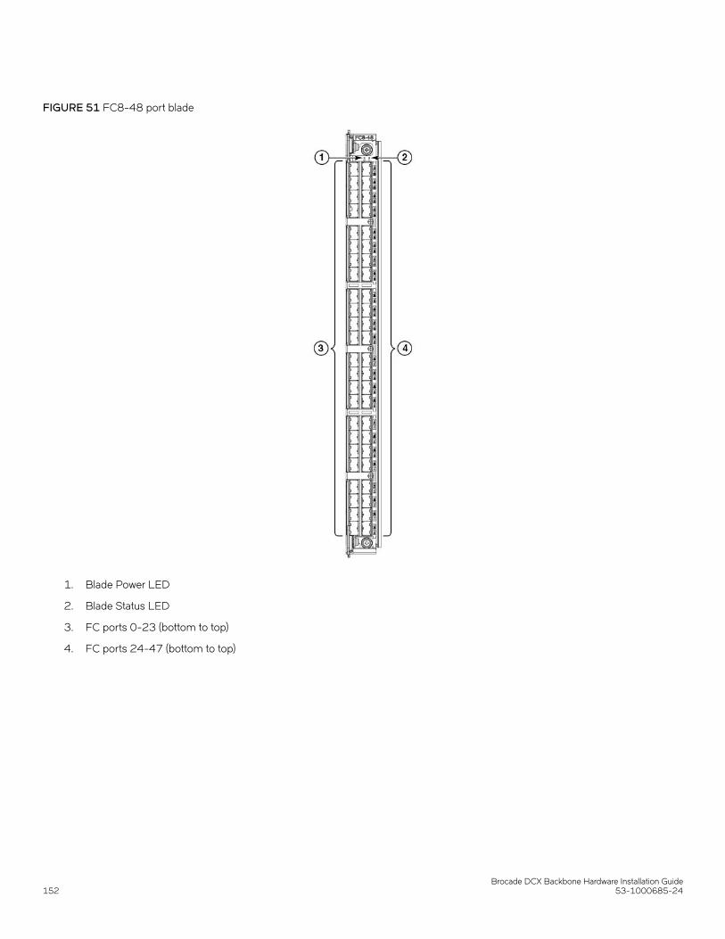
FIGURE 51 FC8-48 port blade
1. Blade Power LED
2. Blade Status LED
3. FC ports 0-23 (bottom to top)
4. FC ports 24-47 (bottom to top)
Brocade DCX Backbone Hardware Installation Guide152 53-1000685-24

FIGURE 52 FC8-64 port blade
1. Blade Status LED
2. Blade Power LED
3. Port 63
4. Port 30
5. port 61 LED
6. port 29 LED
7. FC ports 32-63 (bottom to top)
8. FC ports 0-31 (bottom to top)
Brocade DCX Backbone Hardware Installation Guide53-1000685-24 153

FIGURE 53 FS8-18 encryption blades
Brocade DCX Backbone Hardware Installation Guide154 53-1000685-24
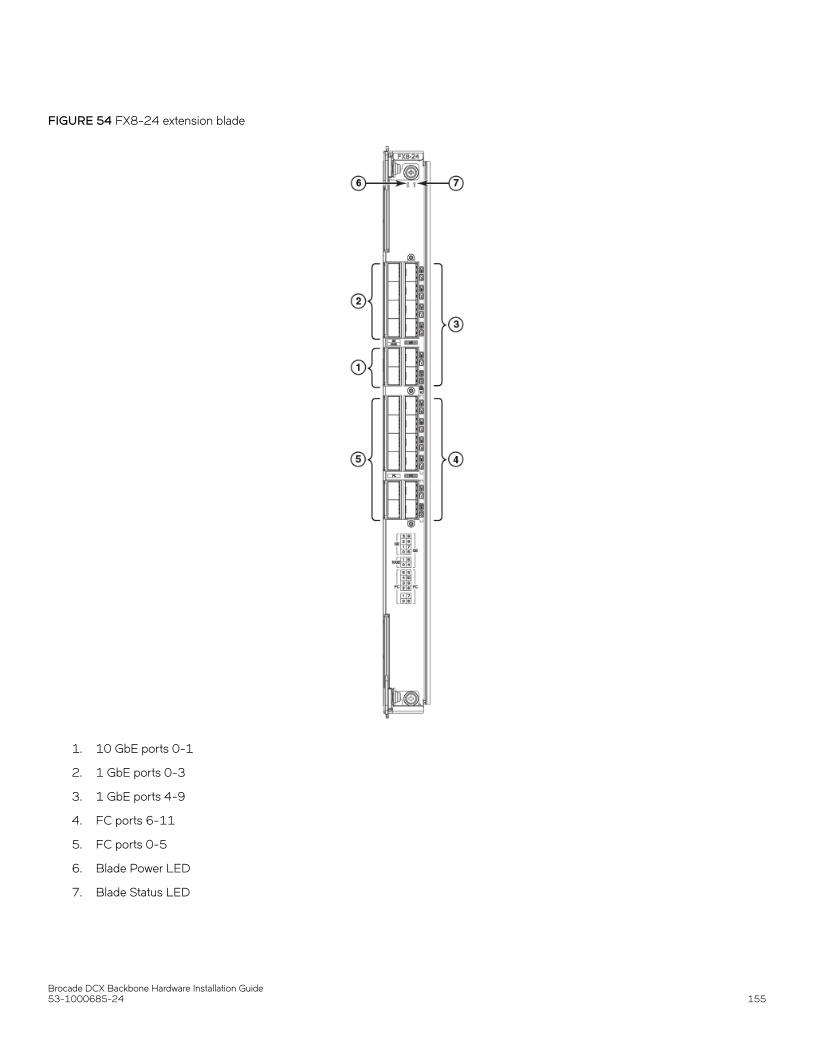
FIGURE 54 FX8-24 extension blade
1. 10 GbE ports 0-1
2. 1 GbE ports 0-3
3. 1 GbE ports 4-9
4. FC ports 6-11
5. FC ports 0-5
6. Blade Power LED
7. Blade Status LED
Brocade DCX Backbone Hardware Installation Guide53-1000685-24 155
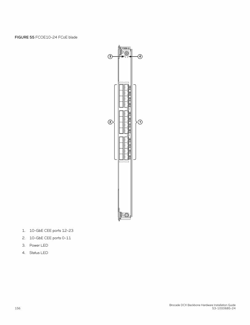
FIGURE 55 FCOE10-24 FCoE blade
1. 10-GbE CEE ports 12-23
2. 10-GbE CEE ports 0-11
3. Power LED
4. Status LED
Brocade DCX Backbone Hardware Installation Guide156 53-1000685-24

Regulatory Statements• BSMI statement (Taiwan).............................................................................................................................................................................157• Canadian requirements................................................................................................................................................................................ 157• CE statement....................................................................................................................................................................................................157• China ROHS.....................................................................................................................................................................................................158• FCC warning (US only).................................................................................................................................................................................158• KCC statement (Republic of Korea).........................................................................................................................................................158• VCCI statement............................................................................................................................................................................................... 158
BSMI statement (Taiwan)
Warning:
This is Class A product. In a domestic environment this product may cause radio interference in which case the user may be required totake adequate measures.
Canadian requirementsThis Class A digital apparatus meets all requirements of the Canadian Interference-Causing Equipment Regulations, ICES-003 Class A.
Cet appareil numérique de la classe A est conforme à la norme NMB-003 du Canada.
CE statementATTENTIONThis is a Class A product. In a domestic environment, this product might cause radio interference, and the user might berequired to take corrective measures.
The standards compliance label on this device contains the CE mark which indicates that this system conforms to the provisions of thefollowing European Council directives, laws, and standards:
• Electromagnetic Compatibility (EMC) Directive 2014/30/EU
• Low Voltage Directive (LVD) 2014/35/EU
• EN 55032/EN 55024 (European Immunity Requirements)
– EN61000-3-2/JEIDA (European and Japanese Harmonics Spec)– EN61000-3-3
Brocade DCX Backbone Hardware Installation Guide53-1000685-24 157

China ROHSRefer to the latest revision of the China ROHS document (P/N 53‐1000428‐xx) which ships with the product.
FCC warning (US only)This equipment has been tested and complies with the limits for a Class A computing device pursuant to Part 15 of the FCC Rules.These limits are designed to provide reasonable protection against harmful interference when the equipment is operated in a commercialenvironment.
This equipment generates, uses, and can radiate radio frequency energy, and if not installed and used in accordance with the instructionmanual, might cause harmful interference to radio communications. Operation of this equipment in a residential area is likely to causeharmful interference, in which case the user will be required to correct the interference at the user’s own expense.
KCC statement (Republic of Korea)
Class A device (Broadcasting Communication Device for Office Use): This device obtained EMC registration for office use (Class A), andmay be used in places other than home. Sellers and/or users need to take note of this.
VCCI statement
This is a Class A product based on the standard of the Voluntary Control Council for Interference by Information Technology Equipment(VCCI). If this equipment is used in a domestic environment, radio disturbance might arise. When such trouble occurs, the user might berequired to take corrective actions.
China ROHS
Brocade DCX Backbone Hardware Installation Guide158 53-1000685-24

Brocade DCX Backbone TechnicalSpecificationsThis document highlights the features and specifications for the Brocade DCX Backbone.
System specificationsSystem component Description
Enclosure 14U, rack-mountable chassis in a standard 19-inch EIA cabinet
Power inlet C20
Power supplies Two 2000 W AC power supply modules (100-240 VAC auto-sensing), 2N redundancy
Fans Three blower assembly modules (two required for operation)
Cooling Rear panel-to-door airflow
System architecture 8 Gbps Fibre Channel modular network switching platforms
System processors FreeScale 8548, 1.2 GHz
Fibre ChannelSystem component Description
Fibre Channel ports Up to 512 ports, universal (E_Port, F_Port, FL_Port, Ex_Port, and M_Port)
ANSI Fibre Channel protocol FC-PH (Fibre Channel Physical and Signalling Interface standard)
Modes of operation Fibre Channel Class 2, Class 3, and Class F
Fabric initialization Complies with FC-SW 5.0
FCIP (IP over Fibre Channel) Complies with FC-IP 2.3 of the FCA profile
LEDsSystem component Description
Status Indicates the blade activity and status.
Power Indicates whether the device is powered on correctly.
Port Indicates the port speed and activity.
Link Indicates whether the inter-chassis link (ICL) cable is correctly installed.
ATTN Indicates whether the blade requires attention.
Brocade DCX Backbone Hardware Installation Guide53-1000685-24 159

OtherSystem component Description
Serial cable RS-232 serial cable
RJ-45 to DB9 adapter RS-232 cable has an adapter at one end that can be removed to provide an RJ-45 style connector
RJ-45 connector Serial port 10/100/1000 Ethernet (RJ-45) per control processor
Weight and physical dimensionsFully loaded: Brocade DCX Backbone 512-port configuration with eight FC8-64 port blades.
Model Height Width Depth Weight (empty) Weight (fully loaded)
Brocade DCX 61.24 cm
24.11 in
43.74 cm
17.22 in
Without door: 61.19cm, 24.09 in
With door: 73.20 cm,28.82 in
39.55 kg
87.20 lb
159.20 kg
351 lb
Environmental requirementsCondition Operational Non-operational
Ambient temperature 0°C to 40°C (32°F to 104°F) –25°C to 70°C (–13°F to 158°F)
Relative humidity (non-condensing)
20% to 85% at 40°C (104°F) 10% to 93% at 70°C (158°F)
Altitude (above sea level) 0-3000 meters (10,000 feet) 0 to 12,000 meters (40,000 feet)
Shock 20 G, 6 ms, half-sine wave 33 G, 11 ms, half-sine wave
Vibration 0.5 G p-p, 5 to 500 Hz 2.0 G p-p, 5 to 500 Hz
Airflow 595 cmh (350 cfm) N/A
Heat dissipation Minimum 16-port configuration of 825.3 W, 2814BTU/hr
Maximum 512-port configuration of 1930.1 W, 6582BTU/hr (200 V)
N/A
Power supply specifications (per PSU)Power supplymodel
Maximum outputpower rating (DC)
Input voltage Input linefrequency
Maximum inputcurrent
Input lineprotection
Maximum inrushcurrent
XBR-DCX-0104 1000/2000 W 1000 W Output100 - 120 V(nominal)
85 - 132 V (range)
2000 W Output200 - 240 V(nominal)
50/60 Hz(nominal)
47 - 63 Hz (range)
15 A Line & Neutral
Fused
20 A maximum,peak
Other
Brocade DCX Backbone Hardware Installation Guide160 53-1000685-24
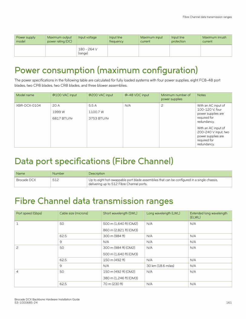
Power supplymodel
Maximum outputpower rating (DC)
Input voltage Input linefrequency
Maximum inputcurrent
Input lineprotection
Maximum inrushcurrent
180 - 264 V(range)
Power consumption (maximum configuration)The power specifications in the following table are calculated for fully loaded systems with four power supplies, eight FC8-48 portblades, two CP8 blades, two CR8 blades, and three blower assemblies.
Model name @100 VAC input @200 VAC input @-48 VDC input Minimum number ofpower supplies
Notes
XBR-DCX-0104 20 A
1999 W
6817 BTU/hr
5.5 A
1100.7 W
3753 BTU/hr
N/A 2 With an AC input of100-120 V, fourpower supplies arerequired forredundancy.
With an AC input of200-240 V input, twopower supplies arerequired forredundancy.
Data port specifications (Fibre Channel)Name Number Description
Brocade DCX 512 Up to eight hot-swappable port blade assemblies that can be configured in a single chassis,delivering up to 512 Fibre Channel ports.
Fibre Channel data transmission rangesPort speed (Gbps) Cable size (microns) Short wavelength (SWL) Long wavelength (LWL) Extended long wavelength
(ELWL)
1 50 500 m (1,640 ft) (OM2)
860 m (2,821 ft) (OM3)
N/A N/A
62.5 300 m (984 ft) N/A N/A
9 N/A N/A N/A
2 50 300 m (984 ft) (OM2)
500 m (1,640 ft) (OM3)
N/A N/A
62.5 150 m (492 ft) N/A N/A
9 N/A 30 km (18.6 miles) N/A
4 50 150 m (492 ft) (OM2)
380 m (1,246 ft) (OM3)
N/A N/A
62.5 70 m (230 ft) N/A N/A
Fibre Channel data transmission ranges
Brocade DCX Backbone Hardware Installation Guide53-1000685-24 161

Port speed (Gbps) Cable size (microns) Short wavelength (SWL) Long wavelength (LWL) Extended long wavelength(ELWL)
9 N/A 30 km (18.6 miles) N/A
8 50 50 m (164 ft) (OM2)
150 m (492 ft) (OM3)
N/A N/A
62.5 21 m (69 ft) N/A N/A
9 N/A N/A N/A
10 50 300 m (984 ft) (OM3) N/A N/A
62.5 N/A N/A N/A
9 N/A 10 km (6.2 miles) 40 km (24.8 miles)
Serial port specifications (DB9)Pin Signal Description
1 Reserved Reserved
2 TXD (output) Transmit data
3 RXD (input) Receive data
4 Reserved Reserved
5 GND Logic ground
6 Reserved Reserved
7 Reserved Reserved
8 Reserved Reserved
9 Reserved Reserved
Serial port specifications (pinout mini-USB)Pin Signal Description
1 +5V Not used
2 UART0_TX Debug port
3 UART0_RX Console port
4 IN Not used
5 GND Ground
Serial port specifications (pinout RJ-45)Pin Signal Description
1 Not supported N/A
2 Not supported N/A
3 UART1_RXD Receive data
4 GND Logic ground
Serial port specifications (DB9)
Brocade DCX Backbone Hardware Installation Guide162 53-1000685-24

Pin Signal Description
5 GND Logic ground
6 UART1_TXD Transmit data
7 Not supported N/A
8 Not supported N/A
Serial port specifications (protocol)Parameter Value
Baud 9600
Data bits 8
Parity None
Stop bits 1
Flow control None
Regulatory compliance (EMC)• FCC Part 15, Subpart B (Class A)
• EN 55022 (CE mark) (Class A)
• EN 55024 (CE mark) (Immunity) for Information Technology Equipment
• ICES-003 (Canada) (Class A)
• AS/NZ 55022 (Australia) (Class A)
• VCCI (Japan) (Class A)
• EN 61000-3-2
• EN 61000-3-3
• EN 61000-6-1
Regulatory compliance (safety)• CAN/CSA-C22.2 No. 60950/UL 60950
• EN 60825 Safety of Laser Products
• EN 60950/IEC 60950 Safety of Information Technology Equipment
Regulatory compliance (environmental)• 2011/65/EU - Restriction of the use of certain hazardous substance in electrical and electronic equipment (EU RoHS).
• 2012/19/EU - Waste electrical and electronic equipment (EU WEEE).
• 94/62/EC - packaging and packaging waste (EU).
• 2006/66/EC - batteries and accumulators and waste batteries and accumulators (EU battery directive).
Regulatory compliance (environmental)
Brocade DCX Backbone Hardware Installation Guide53-1000685-24 163

• 1907/2006 of the European Parliament and of the Council of 18 December 2006 concerning the Registration, Evaluation,Authorisation and Restriction of Chemicals (EU REACH).
• Section 1502 of the Dodd-Frank Wall Street Reform and Consumer Protection Act of 2010 - U.S. Conflict Minerals.
• 30/2011/TT-BCT - Vietnam circular.
• SJ/T 11363-2006 Requirements for Concentration Limits for Certain Hazardous Substances in EIPs (China).
• SJ/T 11364-2006 Marking for the Control of Pollution Caused by EIPs (China).
Regulatory compliance (environmental)
Brocade DCX Backbone Hardware Installation Guide164 53-1000685-24

Caution and Danger Notices• Cautions..............................................................................................................................................................................................................165• Danger notices.................................................................................................................................................................................................166
CautionsA Caution statement alerts you to situations that can be potentially hazardous to you or cause damage to hardware, firmware, software, ordata.
Ein Vorsichthinweis warnt Sie vor potenziellen Personengefahren oder Beschädigung der Hardware, Firmware, Software oder auch voreinem möglichen Datenverlust
Un message de mise en garde vous alerte sur des situations pouvant présenter un risque potentiel de dommages corporels ou dedommages matériels, logiciels ou de perte de données.
Un mensaje de precaución le alerta de situaciones que pueden resultar peligrosas para usted o causar daños en el hardware, el firmware,el software o los datos.
CAUTIONBefore plugging a cable into any port, be sure to discharge the voltage stored on the cable by touching the electricalcontacts to ground surface.
VORSICHT Bevor Sie ein Kabel in einen Anschluss einstecken, entladen Sie jegliche im Kabel vorhandene elektrische Spannung, indemSie mit den elektrischen Kontakten eine geerdete Oberfläche berühren.
MISE EN GARDE Avant de brancher un câble à un port, assurez-vous de décharger la tension du câble en reliant les contacts électriques à laterre.
PRECAUCIÓN Antes de conectar un cable en cualquier puerto, asegúrese de descargar la tensión acumulada en el cable tocando lasuperficie de conexión a tierra con los contactos eléctricos.
CAUTIONMake sure the airflow around the front, and back of the device is notrestricted.
VORSICHT Stellen Sie sicher, dass an der Vorderseite, den Seiten und an der Rückseite der Luftstrom nicht behindert wird.
MISE EN GARDE Vérifiez que rien ne restreint la circulation d'air devant, derrière et sur les côtés du dispositif et qu'elle peut se faire librement.
PRECAUCIÓN Asegúrese de que el flujo de aire en las inmediaciones de las partes anterior, laterales y posterior del instrumento no estérestringido.
CAUTIONNever leave tools inside the chassis.
VORSICHT Lassen Sie keine Werkzeuge im Chassis zurück.
MISE EN GARDE Ne laissez jamais d'outils à l'intérieur du châssis
PRECAUCIÓN No deje nunca herramientas en el interior del chasis.
Brocade DCX Backbone Hardware Installation Guide53-1000685-24 165

CAUTIONTo prevent damage to the chassis and components, never attempt to lift the chassis using the fan or power supply handles.These handles were not designed to support the weight of the chassis.
VORSICHT Alle Geräte mit Wechselstromquellen sind nur zur Installation in Sperrbereichen bestimmt. Ein Sperrbereich ist ein Ort, zudem nur Wartungspersonal mit einem Spezialwerkzeug, Schloss und Schlüssel oder einer anderen Schutzvorrichtung Zuganghat.
MISE EN GARDE Pour éviter d'endommager le châssis et les composants, ne jamais tenter de soulever le châssis par les poignées duventilateur ou de l'alimentation. Ces poignées n'ont pas été conçues pour supporter le poids du châssis.
PRECAUCIÓN Para prevenir daños al chasis y a los componentes, nunca intente levantar el chasis usando las asas de la fuente dealimentación o del ventilador. Tales asas no han sido diseñadas para soportar el peso del chasis.
CAUTIONDo not use the port cover tabs to lift the module. They are not designed to support the weight of the module, which can falland be damaged.
VORSICHT Verwenden Sie nicht die Laschen der Anschlussabdeckungen um ein Modul anzuheben. Diese sind nicht auf das Gewicht desModuls ausgelegt, welches herunterfallen und dabei beschädigt werden kann.
MISE EN GARDE N'utilisez pas les languettes du boîtier du port pour soulever le module. Elles ne sont pas conçues pour supporter le poids dumodule, qui peut tomber et être endommagé.
PRECAUCIÓN No utilice las pestañas de la tapa del puerto para levantar el módulo. No están diseñadas para soportar el peso del módulo,por lo que este podría caerse y resultar dañado.
Danger noticesA Danger statement indicates conditions or situations that can be potentially lethal or extremely hazardous to you. Safety labels are alsoattached directly to products to warn of these conditions or situations.
Ein Gefahrenhinweis warnt vor Bedingungen oder Situationen die tödlich sein können oder Sie extrem gefährden können.Sicherheitsetiketten sind direkt auf den jeweiligen Produkten angebracht um vor diesen Bedingungen und Situationen zu warnen.
Un énoncé de danger indique des conditions ou des situations potentiellement mortelles ou extrêmement dangereuses. Des étiquettesde sécurité sont posées directement sur le produit et vous avertissent de ces conditions ou situations.
Una advertencia de peligro indica condiciones o situaciones que pueden resultar potencialmente letales o extremadamente peligrosas.También habrá etiquetas de seguridad pegadas directamente sobre los productos para advertir de estas condiciones o situaciones.
DANGERUse safe lifting practices when moving the product.
GEFAHR Beim Bewegen des Produktes ist auf eine sichere Hubtechnik zu achten.
DANGER Utiliser des techniques de levage sûres pour déplacer le produit.
PELIGRO Tenga mucho cuidado al levantar el producto para moverlo
DANGERThis device might have more than one power cord. To reduce the risk of electric shock, disconnect all power cords beforeservicing.
GEFAHR Dieses System ist möglicherweise mit mehr als einem Netzkabel ausgestattet. Trennen Sie stets die Verbindung allerNetzkabel, bevor Sie Wartungsarbeiten durchführen, um dieGefahr eines Stromschlags auszuschließen.
DANGER Ce commutateur peut comporter plusieurs cordons d'alimentation. Pour réduire les risques de choc électrique, déconnecteztous les cordons d’alimentation avant d’effectuerl’entretien de l’appareil.
Danger notices
Brocade DCX Backbone Hardware Installation Guide166 53-1000685-24

PELIGRO Este conmutador podría tener más de un cable de alimentación. Para reducir el riesgo de sufrir una descarga eléctrica,desconecte todos los cables de alimentación antes de proceder con la reparación.
DANGERFor safety reasons, the ESD wrist strap should contain a series 1 megaohm resistor.
GEFAHR Aus Sicherheitsgründen sollte ein EGB-Armband zum Schutz von elektronischen gefährdeten Bauelementen mit einem 1Megaohm-Reihenwiderstand ausgestattet sein.
DANGER Pour des raisons de sécurité, la dragonne ESD doit contenir une résistance de série 1 méga ohm.
PELIGRO Por razones de seguridad, la correa de muñeca ESD deberá contener un resistor en serie de 1 mega ohmio.
DANGERMake sure the rack housing the device is adequately secured to prevent it from becoming unstable or falling over.
GEFAHR Stellen Sie sicher, dass das Gestell für die Unterbringung des Geräts auf angemessene Weise gesichert ist, so dass dasGestell oder der Schrank nicht wackeln oder umfallen kann.
DANGER Vérifiez que le bâti abritant le dispositif est bien fixé afin qu'il ne devienne pas instable ou qu'il ne risque pas de tomber.
PELIGRO Verifique que el bastidor que alberga el instrumento está asegurado correctamente para evitar que pueda hacerse inestable oque caiga.
DANGERTurn off the power switches and disconnect the power cords.
GEFAHR Netzschalter ausschalten und Netzkabel abziehen.
DANGER Mettre les interrupteurs hors tension et débrancher les câbles d’alimentation.
PELIGRO Apague los interruptores de alimentación y desconecte los cables de alimentación
Danger notices
Brocade DCX Backbone Hardware Installation Guide53-1000685-24 167


![SAN MONITORING - Zabbix · Infrastructure High Availability 4 x Brocade DCX 8510[640 ports x switch] 6 x Brocade 48000 [768 ports x switch] 4 x Brocade 4900 [128 ports x switch]](https://img.dokumen.tips/doc/110x75/5c73b14309d3f2d37b8bbee2/san-monitoring-zabbix-infrastructure-high-availability-4-x-brocade-dcx-8510640.jpg)